Embed Size (px)
Citation preview

XA9743666
IAEA-TECDOC-771
Manual onsafe production, transport,
handling and storageof uranium hexafluoride
WJINTERNATIONAL ATOMIC ENERGY AGENCY
November 1994

The IAEA does not normally maintain stocks of reports in this series.However, microfiche copies of these reports can be obtained from
IN IS ClearinghouseInternational Atomic Energy AgencyWagramerstrasse 5P.O. Box 100A-1400 Vienna, Austria
Orders should be accompanied by prepayment of Austrian Schillings 100,in the form of a cheque or in the form of IAEA microfiche service couponswhich may be ordered separately from the INIS Clearinghouse.

IAEA-TECDOC-771
Manual ontransport,
hexafluoride
INTERNATIONAL ATOMIC ENERGY AGENCY

The originating Section of this document in the IAEA was:
Nuclear Materials and Fuel Cycle Technology SectionInternational Atomic Energy Agency
Wagramerstrasse 5P.O. Box 100
A-1400 Vienna, Austria
MANUAL ONSAFE PRODUCTION, TRANSPORT, HANDLING AND STORAGE OF
URANIUM HEXAFLUORIDE
IAEA, VIENNA, 1994IAEA-TECDOC-771
ISSN 1011-4289
© IAEA, 1994
Printed by the IAEA in AustriaNovember 1994

FOREWORD
This document has been prepared for people dealing with UF6. It is intended to be asingle source of basic material on the properties and potential problems associated withUF6. As such, all people who intend to produce, handle, transport, or store UF6 should findin this volume an extensive description of the processes and the properties of the materialwith which they will be dealing. This document should also be valuable not only for thosewho do not yet deal with UF6, but also for those who wish to review aspects of theirprogrammes, such as quality assurance, safety and emergency preparedness. The materialspresented include: UF6 properties; properties of associated products and waste materials;safety concerns in production, handling, transport and storage of UF6; and descriptivematerials of quality assurance programmes, safety analysis programmes, and emergencypreparedness and response programmes.
Uranium hexafluoride occupies a key position in the nuclear fuel cycle because of itsuse in the most common enrichment processes. Efforts to promote the safe transport ofUF6 have been made by the IAEA in the framework of transportation of radioactivematerials. However, the operations involving UF6 (production in the conversion plants,management in the enrichment plants, handling in fuel fabrication facilities and storage ofsignificant quantities of the depleted material) are numerous and have very differentcharacteristics.
The purpose of this document is to provide guidance to technical personnel andfacility operators. The radiological and toxicological properties of the materials involved inUF6 production and use are known. The hazards and risks to workers, the public and theenvironment, are also known. However, a comprehensive single document collecting allthis information on UF6 has not existed. The information contained in this publication willalso help the public to understand that nuclear fuel cycle operations are conducted safely.
Work on this subject was initiated by a Consultants meeting convened in November1988, followed by an Advisory Group meeting in June 1989 and another Consultantsmeeting in April 1990. Consultants from Argentina, Canada, France, Japan, theNetherlands, Sweden, the United Kingdom, the USA and the former USSR attended themeetings and prepared a draft of this document.
The IAEA wishes to express its gratitude to those who took part in the preparationof this document and in particular to Mr. J.P. Didyk (Canada), Chairman of the Group ofConsultants, Mr. R.T. Tanaka (Canada), Mr. J. Amamoto (Japan), Mr. B.G. Dekker(Netherlands), Mr. T.J. Hayes (United Kingdom), and Ms. H. Henson and Mr. W.E. Sykes(USA) for their valuable contribution.
The IAEA officers responsible for this publication were Mr. J.L. Rojas andMr. J. Finucane, of the Division of Nuclear Fuel Cycle and Waste Management.

EDITORIAL NOTE
In preparing this document for press, staff of the IAEA have made up the pages from theoriginal manuscript (s). The views expressed do not necessarily reflect those of the governments of thenominating Member States or of the nominating organizations.
The use of particular designations of countries or territories does not imply any judgement bythe publisher, the IAEA, as to the legal status of such countries or territories, of their authorities andinstitutions or of the delimitation of their boundaries.
The mention of names of specific companies or products (whether or not indicated as registered)does not imply any intention to infringe proprietary rights, nor should it be construed as anendorsement or recommendation on the part of the IAEA.
CONTENTS
CHAPTER 1. INTRODUCTION 9
CHAPTER 2. PROPERTIES OF UF6 AND OTHER URANIUM COMPOUNDS 11
2.1. Physical properties 112.2. Chemical properties 122.3. Hazards and precautions associated with release of UF6 132.4. Hazards of uranyl fluoride 142.5. Hazards of hydrogen fluoride 152.6. Compatibility 172.7. Radioactivity of UF6 182.8. Natural UF6 182.9. UF6 from irradiated uranium 192.10. Criticality 20
CHAPTER 3. PRODUCTION AND HANDLING 23
3.1. Introduction 233.2. Uranium refining and conversion (U3O8 -* UF6) 233.3. Enrichment 25
3.3.1. Introduction 253.3.2. Gaseous diffusion process 283.3.3. Centrifuge process 28
3.4. Reconversion processes (UF6 ~» UO2 or U3O8 or UF4) 293.4.1. Introduction 293.4.2. Conversion to UO2 29
3.4.2.1. The AUC process 303.4.2.2. The ADU process 313.4.2.3. The IDR process 323.4.2.4. The GECO process 333.4.2.5. The fluidized bed process 34
3.4.3. Reconversion to U3O8 343.4.4. Reconversion to UF4 34
3.5. Supporting operations 353.5.1. UF6 feeding 363.5.2. UF6 withdrawal 363.5.3. UF6 cylinder handling 363.5.4. UF6 cylinder weighing 373.5.5. Transferring of UF6 from cylinder to cylinder 373.5.6. Sampling UF6 from cylinder 40
3.6. Safety concerns when handling and processing UF6 413.6.1. General 413.6.2. Physical state and pressure of UF6 in process plant operations 413.6.3. Categorization of building areas 423.6.4. Specific safety consideration for area categories 423.6.5. Liquid UF6 handling 423.6.6. UF6 cylinders 433.6.7. Cylinder filling 443.6.8. Cylinder heating 453.6.9. Plant components and connecting lines 45
3.7. Other safety concerns 463.7.1. Conversion and reconversion operations 46
3.7.1.1. Design and equipment 463.7.1.2. Process chemicals 47

3.7.1.3. Personnel 473.7.2. Safety considerations - UO3 to UO2 483.7.3. Safety consideration - Fluorination of UF4 to UF6 483.7.4. Safety - Cell maintenance 49
3.7.4.1. Cell removal 493.7.4.2. Electrolyte transfer 49
3.7.5. Safety - Fluorine and fluorine passivation 503.7.6. Safety of reconversion operations of UF6 to UO2, to U3O8 or to UF4 . . . 503.7.7. Safety - Liquid effluent 50
CHAPTER 4. TRANSPORT 51
4.1 . General regulations for the safe transport of radioactive material 514.2. The special case of UF6 524.3. Present practice for UF6 transport 524.4. New recommendations for UF6 transport 564.5. Uranium hexafluoride packages 56
4.5.1. Cylinders 564.5.2. Outer packaging 564.5.3. Stowing and fastenings for transport 56
4.6. Other transport considerations 574.6.1. Organization of transport 584.6.2. The choice of carrier 58
4.7. Transport documents of international organizations 584.8. Transportation documents of regional or national organizations 584.9. Philosophy of the regulations 59
CHAPTER 5. STORAGE OF URANIUM HEXAFLUORIDE 61
5.1. Introduction and general considerations 615.1.1. General criteria for UF6 storage 62
5.2. Organization 625.3. Quality assurance and quality control aspects of UF6 storage 635.4. Site selection and criteria 63
5.4.1. Selection 635.4.2. Site criteria 64
5.5. Equipment and capability needs for a storage facility 655.6. Security 655.7. Criteria applicable to the storage of cylinders of UF6 where criticality is
of concern 655.7.1. Administrative criteria 655.7.2. Nuclear criticality safety practices 655.7.3. UF6 enriched to greater than 5% 235U 665.7.4. UF6 enriched from 1.0% up to 5% 235U 66
5.8. Criteria applicable to non-fissile and fissile excepted UF6 675.9. Radiological and chemical considerations 675.10. Emergency planning 675.11. Handling, shipping, and receiving cylinders 67
5.11.1. Storage status 675.11.2. Storage and transport interface 68
5.12. Orientation and stacking of cylinders 685.12.1. Natural and depleted material 685.12.2. Fissile UF6 68
5.13. Accountability and inventory 685.14. Corrosion aspects 695.15. Monitoring and inspection activities 72

5.15.1. Cylinders scheduled for storage 725.15.2. Cylinders in storage status 735.15.3. Cylinder storage areas 73
5.16. Cleaning and maintenance 73
CHAPTER 6. RADIOACTIVE WASTE MANAGEMENT 75
6.1. Sources and types of radioactive waste at conversion plants 756.2. Sources and types of radioactive waste at UF6 enrichment plants 786.3. Sources and types of radioactive waste at reconversion plants 786.4. Safety principles and requirements 78
CHAPTER 7. QUALITY ASSURANCE 81
7.1. Introduction 817.2. Scope 817.3. Quality assurance programmes 81
CHAPTER 8. SAFETY ANALYSIS 85
8.1. Introduction 858.2. The safety analysis process 858.3. Topics and guides for safety analyses for activities and facilities 86
8.3.1. Site characteristics 868.3.2. Facility and process/operation systems-description-design features . . . 878.3.3. Principal design bases and criteria 878.3.4. Safety structures, systems and components (SSC) 878.3.5. Waste confinement and management 878.3.6. Facility safety programme 888.3.7. Analysis of normal operations 898.3.8. Accident analysis 898.3.9. Conduct of operations 908.3.10. Operational safety requirements 908.3.11. Quality assurance 90
8.4. Topics for safety analyses for transportation, shipping and packaging 908.4.1. General description 908.4.2 Structural evaluation 918.4.3. Thermal evaluation 918.4.4. Containment 918.4.5. Shielding evaluation 918.4.6. Nuclear criticality evaluation 918.4.7. Operating procedures 918.4.8. Acceptance tests and maintenance programme 918.4.9. Quality assurance 91
APPENDIX A. SUGGESTED FORMAT AND CONTENT FOR EMERGENCY PLANSFOR FUEL CYCLE AND MATERIALS FACILITIES 93
A.1. INTRODUCTION 93A.2. FORMAT 93A.3. EXAMPLE EMERGENCY PLAN 94
1. Facility description 941.1. Description of licensed activity 941.2. Description of facility and site 941.3. Description of area near the site 95
2. Types of accidents 952.1. Description of postulated accidents 95

2.2. Detection of accidents 953. Classification and notification of accidents 96
3.1. Classification system 963.2. Notification and co-ordination 97
3.2.1. Plant emergency 973.2.2. Site emergency 97
3.3. Information to be communicated 974. Responsibilities 98
4.1. Normal facility organization 984.2. Onsite emergency response organization 98
4.2.1. Direction and co-ordination 984.2.2. Onsite staff emergency assignments 98
4.3. Local offsite assistance to facility 994.4. Co-ordination with participating government agencies 99
5. Emergency response measures 1005.1. Activation of emergency response organizations 1005.2. Assessment actions 1005.3. Mitigating actions 1005.4. Protective actions 100
5.4.1. Onsite protective actions 1015.4.2. Offsite protective actions 102
5.5. Exposure control in radiological emergencies 1025.5.1. Emergency radiation exposure control programme 1025.5.2. Decontamination of personnel 102
5.6. Medical transportation 1035.7. Medical treatment 103
6. Emergency response equipment and facilities 1036.1. Command center 1036.2. Communications equipment 103
6.2.1. Onsite communications 1036.2.2. Offsite communications 103
6.3. Onsite medical facilities 1036.4. Emergency monitoring equipment 104
7. Maintaining emergency preparedness capability 1047.1. Written emergency plan procedures 1047.2. Training 1047.3. Drills and exercises 104
7.3.1. Biennial exercises 1057.3.2. Quarterly communications checks 105
7.4. Critiques 1057.5. Independent audit 1057.6. Maintenance and inventory of emergency equipment, instrumentation
and supplies 1057.7. Letters of agreement 106
8. Records and reports 1068.1. Records of incidents 1068.2. Records of preparedness assurance 106
9. Recovery and plant restoration 106
APPENDIX B. EXAMPLES OF INITIATING CONDITIONS 109
REFERENCES 111
GLOSSARY 113
CONTRIBUTORS TO THE DRAFTING AND REVIEW 115

Chapter 1
INTRODUCTION
Uranium hexafluoride (UF6) is a uranium compound used during the enrichment ofuranium to make fuel for nuclear reactors. At room temperature it is a solid but it canreadily undergo changes in state and exist as a gas, or a liquid at slightly elevatedtemperatures. Since fluorine exists naturally in only one isotopic form (19F), the physicalprocesses widely used for enrichment of 235U (diffusion, centrifugation) increase only theconcentrations of U isotopes. It is radioactive because of its uranium content and ischemically reactive because of its high fluorine content. The chemical hazards are moresignificant than the radiological hazards.
Several of the most important steps in the nuclear fuel cycle, namely, uraniumrefining, conversion and enrichment, involve the production, handling, transportation andwaste management of UF6 and related products. Due to the hazardous properties of UF6,these operations must be carried out in a safe manner to protect plant workers, the publicand the environment. Advances in the technology of UF6 processing have been significantin the last twenty-five years and development of safety techniques and protectivemeasures have improved accordingly.
Although the hazardous properties (radioloactive, corrosive and toxic) of the materialsinvolved in UF6 production are well known, a comprehensive document providing safetyguidance from production to waste management has not previously existed in a singlepublication. The purpose of the document is to provide information to technical personneland facility operators on the hazards associated with UF6 operations to ensure that theworkers, the public and the environment are adequately protected.
This document includes a description of the physical, chemical and radiologicalproperties of UF6 and related products, including information concerning their production,handling, storage and transportation and the management of the wastes which result. Allthe operations of UF6 management are considered from a safety point of view. Specialattention has been given to the production of UF6 in the conversion from ore concentratethrough uranium dioxide (UO2) and tetrafluoride (UF4) to UF6. The handling operations inthe conversion facilities, in the uranium enrichment plants and in the fuel fabrication plantshave also been considered. Transport of UF6 is analysed considering the differentmodalities of transport using the publications of the IAEA1. The IAEA organized a series ofmeetings to consider the hazards of UF6 transport since considerable quantities of depleted,natural and enriched UF6 are transported between nuclear fuel sites. Storage of depletedUF6 is another important issue. Factors affecting long term storage are presented,especially site choice and cylinder corrosion. Other topics such as waste management,quality assurance and emergency preparedness which contribute to the overall safety ofUF6 handling, are included. The intention of this document is to provide analysis of thesafety implications of all stages of UF6 operations and to draw attention to specific featuresand properties of importance. References are given to the regulations, recommendationsand advice which govern these operations and which have been prepared by the UnitedNations, the IAEA, and national and international organizations.
1 IAEA-TECDOC-423 [1] and Safety Series No.6 [2] (several revisions) of the IAEA are a veryvaluable reference for UF6 Transport Regulations.

Chapter 2
PROPERTIES OF UFfi AND OTHER URANIUM COMPOUNDS
2 .1 . PHYSICAL PROPERTIES
At ambient temperature, UF6 is a colourless, high molecular weight solid with asignificant but less than atmospheric vapour pressure. It is readily transformed into a gasat atmospheric pressure by raising its temperature above 56.4°C and into a liquid by raisingthe temperature above 64°C and increasing the pressure above 1.5 atmospheres. In thenuclear industry UF6 is handled in all three states during processing stages in the fuel cycle.As processes are conducted in sealed metal containers, UF6 is not directly observable. Inorder to interpret the indirect observations from instrumentation it is important tounderstand the properties of UF6 .
All three phases, solid, liquid and gas, coexist at 64°C (the triple point). Only thegaseous phase exists above 230°C (the critical temperature) at which temperature thecritical pressure is 46.1 atmospheres. The vapour pressure above the solid reaches1 atmosphere at 56°C, the sublimation temperature. A complete phase diagram and vapourpressure/temp relationships are detailed in Figure 2.1.
A large decrease in UF6 density occurs in changing from the solid to the liquid state.Figure 2.2 shows that the expansion of the liquid with increasing temperature is also high.
100,000
10,000
ininUJ(Ea.
1,000
LIQUID
SOLID
(64.02°C.TRIPLE POINT {,137.5 mi
SUBLIMATION POINT 760 mm.
VAPOR
CALC. m
dp
= T(AV) = 0.0439 dg./atm. __
101 I I i I I I I I I l l I i l I60 100 150
TEMPERATURE, °C200 240
FIG. 2.1. Phase diagram of UF6 (a more detailed and comprehensive description of theproperties and characteristics of UF6 is given in Ref. [11]).
11

4.4
4.0
u,
$3.2
2.8
2.4
2.0
1.6
1.2
POINTNO.
123
LIQUID
TEMP. p232.5 1.41217 1.39230.2 1.36
20 40 60 80 100 120 140 160 180 200 220 240TEMPERATURE. °C
FIG. 2.2. Density of solid and liquid UF6
It is essential to control the physical state of UF6 at all times. When restricted volumessuch as traps and containers are filled with UF6, allowance must be made for the volumechanges which arise over the working temperature range to avoid rupture. Data relating thevolumes of several different masses in a Model 48 cylinder are presented in Table 2 .1 .
The relatively small value for the heat of vaporization implies that sublimation andcondensation occur readily. Unexpected material transfer and plugging of lines can result.Since the sublimation temperature lies below the triple point, the pressure must be inexcess of 1.5 atmospheres and the temperature must be above 64°C for UF6 to be a liquid.
2.2. CHEMICAL PROPERTIES
Uranium hexafluoride is a highly reactive material under conditions in which stableuranyl (UO2
+ + ) species can be formed or in which UF6 can behave as an oxidizing agent.An important UF6 reaction is that which occurs with water to form the soluble reactionproducts uranyl fluoride (UO2F2) and hydrogen fluoride (HF), both of which are very toxic.These reactions are strongly exothermic.
(a) In the solid state:
UF6(s) + 2H20(l) ~* UO2F2(s)
where AH = +36.2 kJ/mole UF6.1
4HF(g) + AH
In the solid state the reaction of UF6 with water may be hindered by the formation ofhydrated UO2F2 which covers the UF6 surface, thereby slowing further reaction.
Energy figures derived from US Bureau of Standards Data.
12

TABLE 2.1. VARIATION OF VOLUME OCCUPIED BY UF6 IN MODEL 48Y CYLINDER'TEMPERATURE
WITH
T°C
20658095
112120125
UF6
densityg/cm3
5.090(solid)3.624(hquid)3.532(liquid)3.437(liquid)3.316(liquid)3.263(liquid)3.225(liquid)
Filled 12.5 tonne
m3
2.4563.4493.5393.6363.7693.8303.875
%
60.785.387.690.093.394.895.9
Volume occupied by UFfl
Filled 13 tonne
m3
2.5543.5873.6803.7823.9203.9844.031
%
63.288.891.193.6
bb
b
Filled 13
m3
2.6523.7253.8223.9274.0714.1374.186
.5 tonne
%
65.692.294.6
bb
b
• Model 48Y cylinder volume 4.040 m3.b Overfilled.
(b) In the gas phase:
UF6(g) + 2H20(g) -* UO2F2(s)
where AH = -101.7 kJ/mole HF6.1
4HF(g) + AH
When released to the atmosphere, gaseous UF6 reacts with humidity to formHF-UO2F2. The reaction is very fast and is limited by the availability of water. To hydrolyse1000 kg of UF6 requires 100 kg of water; at 25°C and 70% relative humidity, this amountof water is contained in 6000 m3 of air. Following a large scale release of UF6 outside, thedispersion is governed by meteorological conditions. The plume could still containunhydrolysed UF6 even after travelling a distance of several hundred meters. Afterhydrolysis, uranyl fluoride (UO2F2), usually as a hydrate, can be deposited as a finelydivided solid while HF continues as part of the gas plume. Indoors, the reaction productsform a dense fog seriously reducing visibility and hindering evacuation and emergencyresponse. Fog can also occur in unconfined areas if the humidity is high. Reaction of UF6
with water, which occurs rapidly in the ambient environment, is accelerated in a firebecause of the large quantities of H2O formed in combustion. Reaction of liquid UF6 withhydrocarbon vapours is extremely exothermic with formation of UF4 and low molecularweight fluorinated compounds (CF4, C2F6, etc.). More heat is generally released inhydrocarbon reactions with UF6 than is released in similar reactions with O2.
2.3. HAZARDS AND PRECAUTIONS ASSOCIATED WITH RELEASE OF UF6
The hazards from release of UF6 are mainly inhalation of and ingestion of HF andUO2F2. The hazards of exposure to unhydrolysed UF6 are greater than those involved in thecombined exposure to UO2F2 and HF because the UF6 hydrolysis reaction occurs atsensitive tissues. Currently, there is no data available that demonstrates the extent ofdamage to humans caused by this reaction. The control of UF6 releases requirespreplanning with respect to emergency procedures and equipment. Respiratory protectiveequipment, wooden plugs, patches, a detection and alarm system, and some type ofcooling mechanism should be available in areas where UF6 is processed. Entry into denseclouds from UF6 requires the use of protective clothing and breathing apparatus capableof preventing inhalation of HF and particulates. Skin protection is necessary to preventburns. It is essential that all persons not properly trained and protected be evacuated from
Energy figures derived from US Bureau of Standards Data.
13

areas affected by the release. The wooden plugs should be designed to be inserted intoholes which might occur as a result of broken or defective valves, line breakage, etc.Patches should be shaped to fit contours of the UF6 cylinders to seal a leak.
A UF6 release may be terminated by using patches and plugs depending on thepressure within the system. In some circumstances the release will be terminated byfreezing the UF6 at the leak in the system with appropriate cooling. This cooling is usuallyprovided by a water stream. In no case should water be streamed directly into a cylinderopening. Dry ice or pressurized CO2 from a large-capacity source may be used safely tofreeze off leaks. If the cylinder content is liquid, extended freeze off periods will berequired. It is not practical to attempt to seal a large opening in a liquid UF6 system. Whendealing with enriched UF6, nuclear criticality and safety evaluations should be madebeforehand to assure the absence of unsafe accumulations of uranium.
If the hole or tear in a cylinder is small, the application of wet towels or sponges canplug the hole with hydrolysis products. This works for both solid and liquid UF6. Hydrolysisproducts will develop immediately and provide an effective plug sooner than by freezingthe UF6. Also, the hydrolysis products will not melt.
2.4. HAZARDS OF URANYL FLUORIDE
In accidental releases of UF6, UO2F2 as a solid particulate material may deposit on theground over a large area. There are no internationally accepted values for uraniumcontamination levels for uncontrolled access. However, the value of 0.38 Bq/cm2
(10~5//Ci/cm2) is accepted in many countries [3] for unlimited occupancy of uncontrolledareas. This is equivalent to a ground concentration of approximately 0.1 g/m2 for naturaluranium and to 0.003g/m2for 50% enriched uranium. Uranyl fluoride (UO2F2) is a yellowhygroscopic solid which is very soluble in water. The hazards associated with UO2F2 relateto its radiological, toxic and fissile properties. Fissile properties of UO2F2 are comparableto those of UF6 from which it is produced by hydrolysis. The most important factors arethe enrichment level of uranium and the accident conditions. However, in the case ofreleased gaseous UF6 it is highly improbable that UO2F2 will develop as a critical systemdue to the dilution of the uranium by the dispersion into a greater volume. The radiologicaleffects of UO2F2 can arise from direct inhalation of aerosols of UO2F2 or from secondaryintake associated with environmental contamination from deposition of UO2F2 as a solidaround the incident. UO2F2 is very soluble in water. In lung fluid it is classified as Type Dby the International Commission on Radiological Protection (ICRP); for Type D materials theannual limit of intake (ALI) for uranium is 5 x 10* Bq. This value is based on limitingcommitted dose to the bone surfaces to 500 mSv. The inhalation model upon which thedosimetric considerations are based applies to aerosols in the particle size range 02-10/vwhich is appropriate for atmospheric releases of UF6.
The change of specific activity for uranium upon enrichment is mainly attributable tothe increase in 234U content. For this reason the uranium mass intake for 1 ALI ranges from2000 mg for natural uranium to 20 mg for a 90% 235U enrichment (enrichment of 235U alsoenriches 234U, but to a greater factor — see Section 3.3 below). The toxic daily limit ofintake (TDLI) for soluble uranium compounds is about 2 mg. The comparable radiologicaldaily derived limit of intake (ALI/250) exceeds the toxic restriction only for enrichmentsgreater than 5% 235U In routine daily operations, the exposure limit should be based ontoxicological considerations, for enrichments of up to 5% 235U. It has been estimated thatintakes of 10-25 mg UO2F2 within a short period (30 min) can induce renal damage in anormal adult, while 50% lethality is expected for an intake of 200 mg (Table 2.2) [4].
The toxicological effects of soluble uranium compounds have been discussed by Just[5]. Their findings are summarized in Figure 2.3. In order to obtain the amounts of material
14

TABLE 2.2. COMPARISON OF CHEMICAL TOXICITY AND RADIOTOXICITY OF SOLUBLEURANIUM"
Absorbed dose ofsoluble uranium(mg U/kg)b
0.03
0.058
1.63
19.29
Equivalentradiation dose(Bq)
5.92.103
1.11.104
3.13.10s
3.70.106
Acute health effects
Chemical toxicity
No effect
Renal injury
50% lethality
Lethal
Radiotoxicity
No effect
No effect
No effect
Onset ofradiological effects
• At 97.5% U-235 and 1.14% U-234 enrichment.b Absorbed dose of soluble uranium per kilogram of body weight.
35 000
X C
Z £
e: 3z £
2UJ
cc orO =>
< K
1250
750
650390
RENAL INJURY
EXPOSURE TIME (MINUTES)
FIG. 2.3. Toxicity of acute exposures to soluble uranium.
inhaled, one multiplies [the integrated exposure expressed as U concentration (mg U/m3)]by [exposure duration (minutes)] by [the normal breathing rate (0.02m3/min)]. For example,the Renal Injury Level for exposures shorter than or equal to 30 minutes is1250 (mg U/m3)(min) x 0.02m3/min = 25 mg. An alternative approach to assessing thetoxic implications of a UF6 release in accident conditions has been proposed by Ringot etai. [6] and is illustrated in Table 2.3.
2.5. HAZARDS OF HYDROGEN FLUORIDE
Hydrogen fluoride is a colourless fuming corrosive liquid which boils at 20°C. It is oneof the strongest oxidizing agents known and it is considered to be one of the mostdestructive inorganic agents to human tissue. A distinction is made between anhydrous
15

TABLE 2.3. TOXICITY EFFECTS
Enrichment% 235U
Natural
1
5
10
20
50
9 0
Specificactivity
Bq/g U
2.6 x 10*
2.9 x 10*
1.0 x 105
1.7 x 10⁵
3.5 x 10⁵
1.0 x 10⁶
2.3 x 10⁶
Uranium
mg
1900
1750
500
300
145
50
20
Mass equivalent to 1 ALI
UF6
mg
2800
2600
750
4 5 0
220
75
30
HF
mg
950
900
250
150
75
23
9
(CONCENTRATION)(EXPOSURE
EOUALS53OOO(mg
(mm)
IRRITATION;POSSIBLEHEALTHEFFECTS
SMELL/POSSIBLEIRRITATION
JO 60EXPOSURE TIME (MINUTES)
FIG. 2.4. Toxicity of acute exposures to hydrogen fluoride [1].
hydrogen fluoride (UN2 Number 1052) and an aqueous solution of hydrofluoric acid (UNNumber 1790) which may be less dangerous, depending upon its concentration. Thetoxicology of hydrogen fluoride is discussed, e.g., by Just [7]. The findings are summarizedin Figure 2.4 and Table 2.4.
Table 2.4 refers to different kinds of exposure, because persons can be exposed toHF in normal or accidental conditions. The 2nd, 3rd and 4th values of air concentration ofHF are applicable to workers exposed in routine conditions, such as workers at F2
production facilities or UF6 production or enrichment facilities in normal conditions of
2 For complete information on the materials classification system, the related hazardousproperties, the special and general recommendations relating to specific classes of materials, pleasesee "Recommendations on the Transport of Dangerous Goods", Eighth revised edition, UnitedNations, New York (1993), ST/SG/AC.10/1/Rev.8 (The Orange Book) [8].
16
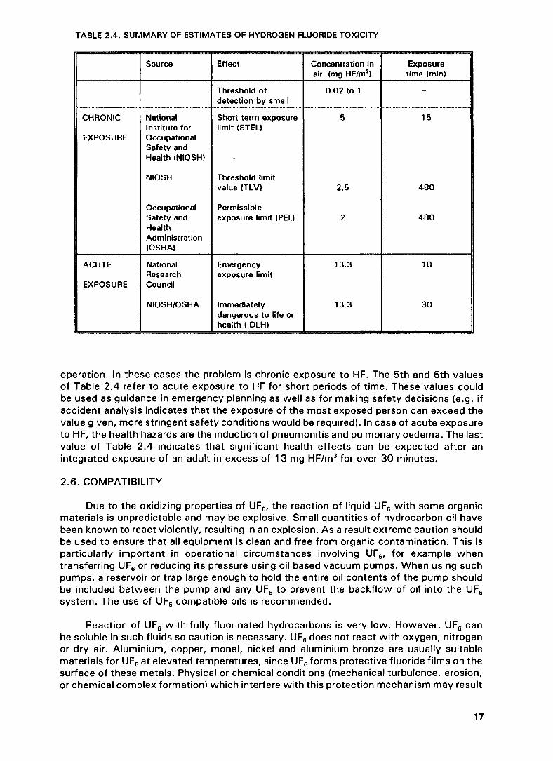
TABLE 2.4. SUMMARY OF ESTIMATES OF HYDROGEN FLUORIDE TOXICITY
CHRONIC
EXPOSURE
ACUTE
EXPOSURE
Source
NationalInstitute forOccupationalSafety andHealth (NIOSH)
NIOSH
OccupationalSafety andHealthAdministration(OSHA)
NationalResearchCouncil
NIOSH/OSHA
Effect
Threshold ofdetection by smell
Short term exposurelimit (STEL)
Threshold limitvalue (TLV)
Permissibleexposure limit (PEL)
Emergencyexposure limit
Immediatelydangerous to life orhealth (IDLH)
Concentration inair (mg HF/m3)
0.02 to 1
5
2.5
2
13.3
13.3
Exposuretime (min)
-
15
480
480
10
30
operation. In these cases the problem is chronic exposure to HF. The 5th and 6th valuesof Table 2.4 refer to acute exposure to HF for short periods of time. These values couldbe used as guidance in emergency planning as well as for making safety decisions (e.g. ifaccident analysis indicates that the exposure of the most exposed person can exceed thevalue given, more stringent safety conditions would be required). In case of acute exposureto HF, the health hazards are the induction of pneumonitis and pulmonary oedema. The lastvalue of Table 2.4 indicates that significant health effects can be expected after anintegrated exposure of an adult in excess of 13 mg HF/m3 for over 30 minutes.
2.6. COMPATIBILITY
Due to the oxidizing properties of UF6, the reaction of liquid UF6 with some organicmaterials is unpredictable and may be explosive. Small quantities of hydrocarbon oil havebeen known to react violently, resulting in an explosion. As a result extreme caution shouldbe used to ensure that all equipment is clean and free from organic contamination. This isparticularly important in operational circumstances involving UF6, for example whentransferring UF6 or reducing its pressure using oil based vacuum pumps. When using suchpumps, a reservoir or trap large enough to hold the entire oil contents of the pump shouldbe included between the pump and any UF6 to prevent the backflow of oil into the UF6
system. The use of UF6 compatible oils is recommended.
Reaction of UF6 with fully fluorinated hydrocarbons is very low. However, UF6 canbe soluble in such fluids so caution is necessary. UF6 does not react with oxygen, nitrogenor dry air. Aluminium, copper, monel, nickel and aluminium bronze are usually suitablematerials for UF6 at elevated temperatures, since UF6 forms protective fluoride films on thesurface of these metals. Physical or chemical conditions (mechanical turbulence, erosion,or chemical complex formation) which interfere with this protection mechanism may result
17

TABLE 2.5. SPECIFIC ACTIVITY AND ALI OF SOLUBLE URANIUM NUCLIDES AND DAUGHTERS
Species
U-232U-234U-235U-236U-238Th-228Th-23OTh-232Th-234
Specific activity
Bq/g
8.3 x 10¹¹
2.31 x 10⁸
8.0 x 10*2.4 x 106
1.2 x 10*3.0 x 1013
7.6 x 10⁸
4.0 x 10³
8.6 x 101*
ALI"
Bq
8x 10³
5 x 10*5x 10*5 x 10*5 x 10*4x 102
2x 10²
407 x 106
• Basic Safety Standards for Radiation Protection, IAEA Safety Series No. 9 (1982) {10).
in unexpected, degradation of the performance of these materials. It is therefore essentialthat design criteria for vessels and process equipment take into consideration the purity ofthe UF6 and velocity and turbulence conditions likely to exist during normal operations.
2.7. RADIOACTIVITY OF UF6
The radioactivity of a mass of UF6 is dependent upon several factors:
origin of uranium, natural or reprocessed,degree of enrichment in 235U,time elapsed since processing,
- radioactive impurities.
The specific activity and annual limits of intake (ALI) for inhalation of soluble speciesof uranium nuclides and daughters are listed in Table 2.5. The corresponding specificactivity of UF6 may be calculated from the ANSI N14.1 formula:
Specific activity (millicuries/lb UF6) = 18.90W4 + 0.028W5 + 0.0001 W8
Specific activity3 (Bq/kg UF6) - 1 .54x10 9W 4 + 2 .28x10 6 W 5 + 8 .15x10 4 W 8
where W4, W5 and W8 are the weight % of the isotopes 234U, 235U and 238U. This equationis based upon a specification for UF6 which includes 0.110 parts 232U and 500 parts 233Uper million parts of 235U. If these nuclides are not present, subtract 0.022 x W5 from theequation. The maximum anticipated activity levels in UF6 shipping containers are given inANSI N14.1 (1987) [9].
2.8. NATURAL UF6
The radioactivity of unirradiated UF6 is governed by 235U enrichment. Natural uraniumhas a specific activity of 2.6 x 10⁴ Bq/g U. The isotopes 234U and 235U each contributeabout half of this activity. With the enrichment of the 235U isotope, the contribution toactivity from 234U which enriches more rapidly than 235U (see Section 3.3), becomes
3 1 mCi = 103 Ci = 103 x 3.70 x 1010 Bq - 3.70 x 10⁷ Bq
3.70 x 10⁷ Bq1 mCi/lb UFf = 8.15 x 10⁷ Bq/kg UF£
0.454 kg
18
dominant. At 5% 235U, 80% of the activity is attributable to the 234U content. Alpha activityfrom uranium presents no hazard as UF6 is always contained in sealed vessels because ofits chemical properties. The chemotoxicity exceeds the radiological for all commonenrichments.
The decay products of uranium include nuclides which emit more penetrating beta andgamma radiation. When UF6 is vaporized from a vessel or transport cylinder these nonvolatile decay products remain and can concentrate on surfaces. Without the shielding andabsorption of the bulk of UF6, the gamma radiation level will be much higher than for thefilled vessel and may be as high as 2 mGy/hour. The highest radiation levels occurimmediately after emptying. They then rapidly decay.
The neutron flux arising from the interaction of alpha radiation with fluorine atoms(a,n) (which rises with increasing enrichment) is of minor significance. The gamma activityarising from 235U (186 keV) can be used with appropriate detectors and multichannelanalyzers to derive the 235U assay of materials within vessels and cylinders.
2.9. UF6 FROM IRRADIATED URANIUM
UF6 produced from irradiated and reprocessed uranium can contain, in addition to234U, 235U, 238U, significant concentrations of:
other uranium isotopes, e.g. 232U, 233U, 236U, 237U,transuranic nuclides, e.g. 237Np, 239Pu,fission product impurities, e.g. 106Ru, "Tc ,
- daughter products of these species, e.g. 228Th, 208TI.
Since the chemical processes do not affect the isotopic composition of uranium, theratios existing at reprocessing continue through subsequent stages of conversion to UF6.An exception is 237U which has a very short half-life (6.75 d) and is a daughter of 241Pu.Removal of Pu and Np can occur during conversion to UF6 especially during the fluorinationstage where the stabilities of PuF6and NpF6 differ from UF6.
Uranium-234, which occurs naturally in unirradiated uranium, is of great significanceto the specific activity of reprocessed uranium. The 234U concentration of uranium isincreased during enrichment of 235U (see Section 3.3 below) by larger factors than is 235U.During burnup in the reactor, 234U is consumed at only half the rate of 235U by neutroninteractions. As a consequence 234U contributes proportionately more to the specificactivity in reprocessed uranium than in the fresh fuel. After re-enrichment, the 234U is mostimportant in calculating the A2 value for transport and in determining the ALI of thematerial.
Uranium-236 is of no special safety concern, but the presence of this isotope is auseful indicator of contamination by irradiated materials. Specification for natural UF6
usually limits this isotope to less than 20 parts per million. This isotope also parasiticallyabsorbs neutrons and is therefore undesirable in nuclear fuel.
The significance of 232U arises from the decay chain through 228Th to the gammaemitting nuciide 208TI. The chain can be broken by chemical processes such as solventextraction or volatilization of members of the chain, but as 232U continues to decay,equilibrium is subsequently re-established with over 30% regrowth in one year. As aconsequence, operations following reprocessing should take place as rapidly as possibleto minimize gamma radiation dose.
The composition of reprocessed uranium will depend upon the reactor type, theburnup, and cooling history, the efficiency of impurity removal in reprocessing and
19

conversion, and the time elapsed since these operations occurred. The conversion ofuranium oxide to UF6 concentrates impurities in the waste stream. In addition, any processin which UF6 is transferred in the gas phase will concentrate non volatile species inresidues. Volatile species such as 106Ru and "Tc can contribute to activity in processvessels and cylinders and can contaminate effluent streams from wet scrubbing processes.Pu and Np can be volatilized in a flame reactor. Neptunium will volatilize in fluidized bedsto a degree while Pu is retained in Ca F2. As a result, provision should be made to includesuch species in site regulation and monitoring procedures.
2.10. CRITICALITY
The distinguishing characteristic of a fissile nuclide such as 235U is that it is capableof initiating a self sustaining neutron chain reaction. A fission chain is propagated byneutrons. Since a chain reaction is dependent upon the behaviour of neutrons, fissilematerials are handled, packaged and shipped under requirements designed to controlneutron behaviour in a manner to ensure subcriticality and, thus, provide criticality safety.
There are three possible fates for a neutron in fissile material: it may encounter afissile nuclide and induce fission, producing neutrons to continue the chain; it may beabsorbed by other materials or by a fissile nuclide without fissioning; it may leak out of thesystem. Criticality is achieved when there is a balance between neutron production byfission and loss by neutron absorption in and leakage from the fissile material. The threepossible outcomes for a neutron are controlled to provide criticality control. The fractionof neutrons leaking is affected by the geometric configuration, both of the individualpackage and of the spacing between packages. Neutrons leaking from a vessel may enterother similar containers and produce a fission. Neutron interaction can be influenced bypackage dimensions, which determine the spacing of the fissile material. Neutrons mayalso be removed from the system by the use of neutron absorbers. Good design embodiesa balance of many parameters and assures subcriticality. This goal is accomplished byemploying specific limits on 235U enrichment, mass, volume, geometry, moderation and
FIG. 2.5. UF6 handling.
20

FIG. 2.6. UF6 handling with crane.
spacing, and, in some instances, utilizing the neutron absorption characteristics of thevessel and cylinder walls.
Figure 2.5 shows a model of a 48 x cylinder which incorporates most of the abovenuclear criticality safety limitations. These same limitations, including temperature controlto prevent rupture in process operations, are specified throughout this report. The amountof UF6 which may be contained in an individual vessel or cylinder and the total number ofvessels or cylinders accumulated as a group are determined by the nuclear properties ofthe UF6 (see Figure 2.6). Spacing of cylinders of enriched UF6 in transit is assured throughthe use of IAEA approved packages.
The use of Models 30 and 48 cylinders at 235U enrichments of 5.0% and 4.5%respectively is dependent upon limiting the availability of hydrogen — a neutron moderator.A hydrogen-to-uranium atomic ratio of less than 0.088, which is equivalent to aspecification of greater than 99.5% UF6 (assuming the impurity is hydrogen). This isrequired by ASTM specifications C787 and C996 (see also Figure 2.7).
The shipment of UF6 of enrichment greater than 1 % but less than 5% 235U requiresthe use of an approved overpack. For enrichments above 5% 235U, geometric and masslimits are employed as well as overpack protection.
Changes in the quantity, form, arrangement, physical or chemical state, or changesin the packaging could affect the neutron multiplication factor and invalidate the TransportIndex4 of the package. The requirements set forth in the certificate of approval for a
4 The Transport Index relates to a package, overpack, tank, or freight container which is usedto provide control over both nuclear criticality safety and radiation exposure.
21

FIG. 2.7. Loading and unloading UF6 cylinders.
package are necessary to assure safety during transport. The criticality safety assessmentperformed includes a range of parameters. These parameter ranges should be described inthe application for transportation approval.
22
Chapter 3
PRODUCTION AND HANDLING
3.1 . INTRODUCTION
An overview of the sequences of operations involving UF6 from uranium ore tonuclear fuel showing the main process operations as well as the supporting operations isgiven below.
Main process operation Supporting operations forprocessing of UF6
Conversion process UF6-withdrawal(U3O8 -* UF6) UF6-sampling and transfer
UF6-cylinder weighingUF6-storage
Enrichment process UF6-feeding(UF6 -• UF6-enriched+ UF6-depleted) UF6-withdrawal
UF6-sampling and transferUF6-cylinder weighingUF6-storage
Reconversion process UF6-feeding(UF6 ~* UO2 or U3O8 or UF4) UF6-sampling and transfer
UF6-cylinder weighingUF6-storage
The main process operations — conversion, enrichment and reconversion — aredescribed in Sections 3.2, 3.3 and 3.4 respectively. The supporting operations aredescribed in Section 3.5.
Section 3.6 describes the safety concerns with handling and processing of UF6 andis relevant to all the three main process operations. In conversion and reconversion,materials other than UF6 are involved; the safety concerns with regard to those materialsare addressed in Section 3.7. The typical appearance of the different uranium products isshown in Figure 3 .1 . Since conversion, enrichment and reconversion are not carried outat one location, inter-site transportation of UF6 is unavoidable. Transportation of UF6 iscovered in Chapter 5. Storage of UF6 may be necessary in support of the processoperations at each site. The storage of UF6 is covered in Chapter 6.
3.2. URANIUM REFINING AND CONVERSION (U3O8 ~» UF6)
There are many facilities operating to convert uranium ore concentrate (yellow-cake)to uranium hexafluoride UF6. The uranium ore concentrate is usually an impure compoundof ammonium NH4, sodium (Na) or magnesium (Mg) diuranate. The various unit operationsin the conversion facilities are illustrated in Table 3.1. As can be seen in the flow diagrams,regardless of the process, the common elements are: the conversion of yellow-cake
23
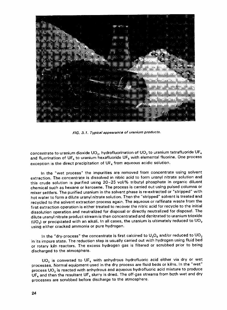
FIG. 3.1. Typical appearance of uranium products.
concentrate to uranium dioxide U02, hydrofluorination of U02 to uranium tetrafluoride UF4
and fluorination of UF4 to uranium hexafluoride UF6 with elemental fluorine. One processexception is the direct precipitation of UF4 from aqueous acidic solution.
In the "wet process" the impurities are removed from concentrate using solventextraction. The concentrate is dissolved in nitric acid to form uranyl nitrate solution andthis crude solution is purified using 20-25 vol/% tributyl phosphate in organic diluentchemical such as hexane or kerosene. The process is carried out using pulsed columns ormixer settlers. The purified uranium in the solvent phase is re-extracted or "stripped" withhot water to form a dilute uranyl nitrate solution. Then the "stripped" solvent is treated andrecycled to the solvent extraction process again. The aqueous or raffinate waste from thefirst extraction operation is either treated to recover the nitric acid for recycle to the initialdissolution operation and neutralized for disposal or directly neutralized for disposal. Thedilute uranyl nitrate product stream is then concentrated and denitrated to uranium trioxide(UO3) or precipitated with an alkali. In all cases, the uranium is ultimately reduced to UO2
using either cracked ammonia or pure hydrogen.
In the "dry-process" the concentrate is first calcined to U3O8 and/or reduced to UO2
in its impure state. The reduction step is usually carried out with hydrogen using fluid bedor rotary kiln reactors. The excess hydrogen gas is filtered or scrubbed prior to beingdischarged to the atmosphere.
UO2 is converted to UF4 with anhydrous hydrofluoric acid either via dry or wetprocesses. Normal equipment used in the dry process are fluid beds or kilns. In the "wet"process UO2 is reacted with anhydrous and aqueous hydrofluoric acid mixture to produceUF4 and then the resultant UF4 slurry is dried. The off-gas streams from both wet and dryprocesses are scrubbed before discharge to the atmosphere.
24

The UF4 is fed in a dry powder state into either tower or fluidized bed fluorinationreactors and reacted with preheated fluorine gas to produce the gaseous UF6 product. Thefluorine used in the production of UF6 is generated by the electrolysis of anhydroushydrofluoric acid in potassium bifluoride. Each converter produces fluorine on site. A typicalfluorine cell-room consist of the number of cells of the required current to provide therequired fluorine production capacity. The actual number and size of cells varies butnormally, cells of 6000 to 12 000 amps each are used. Both fluorine and hydrogen aregenerated during electrolysis. Normally hydrogen is "scrubbed" and flared-off. The rate offluorine generation is controlled by the demand on the UF6 reactors.
The product UF6 in the gaseous state is usually filtered to remove the particulates andcondensed as a solid in cold traps. As required, UF6 is heated to achieve liquefaction andis allowed to drain directly into shipping cylinders where it solidifies. In the process wherethe concentrate is directly reduced, hydrofluorinated and fluorinated to UF6, initiallyproduced impure UF6 is vaporized and fed into distillation columns where fractionaldistillation removes the remaining impurities. Following purification, UF6 is collected in acold trap and then fed directly to shipping cylinders as noted above. After sampling, thecylinder is stored ready for shipment to the various enrichment facilities. All UF6 producedand shipped should meet a standard feed specification (e.g. ASTM C787) [12].
The waste resulting from the refining and conversion of uranium concentrates to UF6
are generally common to all facilities. Waste arises from two sources, waste productsoriginating from the concentrates and waste products originating from the processreagents. In general, wastes are handled by treatment and recycle or treatment anddisposal. All conversion processes use hydrofluoric acid (HF). Because of the environmentaland health impact of this chemical, all effluent streams must be treated to remove the HFand contaminant uranium. In the case of off-gases, HF and uranium removal are achievedwith potassium hydroxide (KOH) scrubbing. The scrub liquor is subsequently filtered toremove the precipitated potassium diuranate and then the filtrate is treated with lime toregenerate KOH and to precipitate the fluoride as calcium fluoride (CaF2). The slurry ofcalcium fluoride/potassium hydroxide (CaF2/KOH) is filtered to remove the CaF2 solids fordisposal and the resultant KOH is recycled.
KOH + HF -» KF + H2O
14KOH + 2UF6 -* K2U2O7 + 12KF + 7H2O
2KF + Ca(0H)2 -* 2KOH + CaF2
3.3. ENRICHMENT
3.3.1. Introduction
A key step in the nuclear fuel cycle is changing the concentration or assay of the 235Uisotope. A higher assay level of 235U than the 0.71 % in natural uranium (generally in therange of three to four percent) is required. This is accomplished through enrichment. Atpresent there are two principal processes in commercial use. Gaseous diffusion is theoldest and represents most of the present capacity. The second method is the gascentrifuge process. In both these enrichment processes, enrichment is accomplished bytaking advantage of the slight difference in the atomic masses of the 235U and 238Uisotopes. Both of these methods require a gaseous form for uranium — hence our interestin UF6 Because each of the enrichment methods described below use the slight differencein mass between 238U and 235U to drive the process, 234U will be enriched by even largerfactors than will be 235U (driven by slightly larger mass differences).
25

TABLE 3.1. CONVERSION PROCESSES
Wet Process
BRITISH NUCLEAR FUELS LTD
HNO3 IBPImpure Solvent
Yeiiowcake • Urany! Nitrate ~~^* F i l t e r • Extraction — ^ * 0 K L i (? u o r " " • • Concentrate
H 2 HF
Denitrate — • U0 o — ! • UO2 - H ^ UF,
COMURHEX
HNO
Yeiiowcake
CAMECO FUEL SERVICES (ELDORADO)
HNOQ
Impure ^ ^ SolventN i t r a t e " • Filter - • E x t r a c t i o n
TBP NH 3
— • O K Liquor - * • ADU Precip — • Filter - • • D r y Calcine
H 2 HF
- H ^ UO2 -§
Yeiiowcake
SEQUOYA FUELS
l m p U r e ^ SolventUranyl Nitrate Extraction
TBP H2 HF
OK Liquor • Concentrate • Denitrate • UO, — • UO
HNOImpure
Uranyl Ni
UO2 Fuel
TBP
Filter.Dry
NH. HNO,3 *
ADU Precip -^§ UNH Soi'n - ^ h
3 ~~ " " 2
AQU HF
UO3
Yeiiowcake
ADU UF.
PNC
H SO7HCLYeiiowcake — - — e»» impure
H 2 HF
— Dry/Calcine — ^ - UFg
Fo
Enaction OK Liquor - • • Concentrate ! • Denitrate UO UO 2 H ^ UF — • UF
FilterUranyl Nitrate
Solvent (TNOA)
Extractionor
ion Exchange
Electrolyticor
ChemicalReduction
I
HF(Sol)
Leaching solution F2(g)
-UF.

TABLE 3.1 . (cont.)
ALLIED SIGNAL
Yeilowcake-
Dry Process
HF F9UO 2 • UF4
£-^- UF6 — • Distillation • UF6
COMURHEX
YellowcakeADU
CalcineH2 HF F2
- • UO 3 • UO 2 *** UF4 • • UFg — • Distillation • UF£

FIG. 3.2. Gaseous diffusion stages.
3.3.2. Gaseous diffusion process
In the gaseous diffusion process uranium containing 238U and 235U, is introduced asgaseous uranium hexafluoride and pumped to higher pressure. The chamber containing theUF6 gas is connected with a similar chamber by barrier tubes — hundreds of millions ofuniformly sized, submicroscopic openings per square inch. The gas molecules containingthe lighter 235U move slightly faster than those containing 238U. Consequently, the gasdiffusing through the barrier tubes is slightly enriched in 235U. The diffused gas,representing about one-half of the stream, is then fed to the next higher stage where theprocess is repeated. The remaining gas flowing within the chamber is recycled to the nextlower stage. Because of the very small amount of separation occurring in one stage, theprocess must be repeated hundreds of times in a series arrangement called a cascade(Figure 3.2).
A gaseous diffusion stage contains a compressor to pump the UF6 gas, an electricmotor to drive the compressor, a process cooler to remove heat created from gascompression, a process control valve to control pressure, and interconnecting piping. Theprocess can be operated at above or below atmospheric pressure. In addition, a uraniumenrichment plant also has: UF6 feed system, UF6 withdrawal system, UF6 cylinder handling,UF6 cylinder weighing, UF6 transfer and sampling systems. These supporting operations aredescribed in Section 3.5.
3.3.3. Centrifuge process
The centrifuge process separates isotopes of uranium by making use of the principleof centrifugal force. When gaseous UF6 is fed into a centrifuge machine which rotates very
28

FIG. 3.3. View of centrifuges in a cascade hall of an enrichment plant.
rapidly, the lighter molecules containing 235U gather along the central axis of the rotor andthe heavier molecules containing 238U move to the outside. The UF6 gas in which 235U isslightly concentrated is drawn from near the axis and is fed to the next stage of thecascade. The UF6 stream containing a higher concentration of 238U is removed from theperiphery and is fed to the next downstage centrifuge. Since the amount of actual isotopeseparation accomplished by a single centrifuge machine is small, many stages must operatein a cascade configuration (Figure 3.3). Since the centrifuge itself functions as a pump, acompressor is not necessary to move the gas to the next stage in the cascade. Thecentrifuge enrichment process operates at sub-atmospheric pressures. Supportingoperations are the same as for a gaseous diffusion plant.
3.4. RECONVERSION PROCESSES (UF6 -* UO2 or U3O8 or UF4)
3.4.1. Introduction
UF6 is converted either to UO2 for fuel fabrication purposes, or to U3O8 or UF4 for longterm storage, or to UF4 for production of uranium metal. These processes have commonrequirements for handling UF6. Brief descriptions are given below of the overall operations.
3.4.2. Conversion to UO2
Enriched UO2 for fuel fabrication is produced from enriched UF6 using either aqueousprocessing routes through precipitation of ammonium diuranate (ADU) or ammonium uranyl
29
RELEASE TOUO2 PELLET SHOP
DECOMPOSITIONAND REDUCTION
ANALYSISQUANTITY
RELEASEFOR
CONVERSION
POWDERf \ PROPERTIESV ) ANALYSIS^ ^ QUANTITY
RECOVERY OF U \AND CHEMICALS ) PRE-
— ~ - — HOMOGENIZATION
FIG. 3.4. AUC process.
carbonate (AUC) or alternatively through gas phase reactions of UF6 with steam andhydrogen using so called dry routes.
3.4.2.1. The AUC process
In the AUC conversion process, gaseous UF6 is fed into a stirred aqueous system atthe same time as gaseous CO2 and NH3 (see Figure 3.4). The resulting reaction is:
UF6 + 5H2O + IONH3 + 3CO2~* (NH4)4 UO2 (CO3)3 + 6NH4F
The ammonium uranyl carbonate precipitate is filtered then subsequently decomposedin a fluidized bed reactor to UO2. Chemical reactions which take place in a fluidized bedare:
(NH4)4UO2(CO 3)3 UO3 + 4NH 3CO 2H2O
UO H UO H,0
For the vaporization of UF6 the low enriched feed cylinders are sealed in autoclaveswhich can be electrically or steam heated (see Figure 3.5). The UF6 cylinder valve can beremotely driven and the line from autoclave to precipitation vessel is electrically heated.The precipitator is usually a critically safe vessel with a circulating loop. The process gasesare fed into this vessel through nozzles within the loop. Off-gases are taken to a jetscrubber then to a spray scrubber and filter system.
30

HP MONITOR
CO2LINEEXHAUSTING DEVICE
UFe — PROCESS LINE TO HYDROLYSIS EQUIPMENT
-©Cxjxj—
PNEUMATICVALVE
REMOTEDRIVE OFCYLINDERVALVE
CONTROL VALVE
MAIN CLOSING VALVE
UF6 CYLINDER
FIG. 3.5. Evaporating equipment.
UFC U0oFo SOLUTION
VAPORIZATIONHYDROLYSIS
PURIFIED WATER
AMMONIA
CYLINDER
CALCINATION U02 POWDERFILTRATION REDUCTION
MILLING Af \ I X X
PRECIPITATION V _ / DRYING
FILTER DRYER ROTARY KILN
FIG. 3.6. ADU process.
3.4.2.2. The ADU process
In the ADU conversion process (see Figure 3.6), UF6 is fed into water to produce asolution of uranyl fluoride (UO2F2) and dilute hydrofluoric acid. This solution is treated withgaseous or aqueous ammonia to precipitate ammonium diuranate. The ADU is filtered andwashed with hot water and then converted to UO2 using hydrogen or cracked ammonia.Some processes calcine to U3O8 before reduction. The overall reactions are:
UF6 -
2UO2
3(NH,
(NH4)
u3o8
uo3
h 2H2O ™*
F2 + 6NH4OH -*
*)2 u 2o 7
2 U2O7
+ 2H2 -»
+ H2 ~*
UO2F2
(NH4)2
2U3O8
2UO3
3UO2
UO2 4
+ 4HF
U2O7 +
+ 6NH
+ 2NH3
+ 2H2O
- H2O
4NH4F +
3 + 3H2O
+ H2O
3H2O
+ O2
31

The fluoride containing filtrate is treated with a calcium salt to precipitate calciumfluoride (CaF2) and regenerate ammonia.
2NH4F + Ca (OH)2 -* CaF2 + 2NH4 OH
The ammonia is recycled to the process. The CaF2 may either be stored or usedindustrially.
In the modified ADU conversion process (see Figure 3.7), hydrolysis of UF inaluminium nitrate solution is followed by TP solvent extraction. The aluminium nitratesolution is provided to complex the fluorine. Uranium, is then precipitated as ADU Fluorinetransferred into raffinate at the solvent extraction step is recovered as aluminium fluoridefor industrial reuse. The overall reaction of the modified ADU conversion process is asfollows:
UF6 + 2AI(NO3)3 + 2H2O
UO2(NO3)2 + 2TBP
2UO2(NO3)2 + 6NH3
3.4.2.3. The IDR process
3H2O
UO2(NO3)2 + 2AIF3 + 4HNO
UO2(NO3)22TBP
(NH4)2 U2O7 + 3NH4NO3
In the integrated dry route (IDR) process (see Figure 3.8), UF6 is converted directlyto a ceramic grade UO2 powder by interaction of UF6 vapour with steam and hydrogen ina rotary Inconel kiln. The kiln is operated with counter current gas-solids flow UFe vapourbeing fed concurrently with steam into the base of a filter hopper at the gas outlet end of
UF6 STORAGEEXTRACTION/STRIP STORAGE TION
FILTER
LIQUID WASTETREATMENT
POWDERSTORAGE
FIG. 3.7. Modified ADU process.
32

UFg VAPORIZATION
UF6 CYLINDER
HYDROGEN
IDR KILN (UF6->UO2)
STEAM
FIG. 3.8. IDR process.
the kiln (see Figure 3.8). The steam reacts with UF6 to produce an intermediate phase ofUO2F2 which is passed into the body of the kiln by means of a scroll feeder. The kilntemperature profile is controlled by a number of zone heaters so that the profile can beadjusted to suit the quality of product required. Pyrohydrolysis and reduction is achievedby a hydrogen and steam feed to the powder discharge end of the kiln. Effluent gases arefiltered before being discharged to a condensation HF recovery and final scrubber system.The intermediate stage and overall reactions are:
UF6
UO2F2
UO,
2H2OH2OH,
UO2F2
U0 3
UO,
4HF2HF
H2O
UF, 2H2O UO, 6HF
3.4.2.4. The GECO: process
In the GECO process (Figure 3.9) vaporized UF6 is fed into a flame reactor in whichU3O8 is formed by reaction with oxygen (air) and hydrogen. This U3O8 is further reducedin a kiln to produce UO2. As in the IDR process HF is recovered for reuse. The intermediatestage and overall reactions are:
O:
+ 1/20
Registered trademark of the General Electric Company.
at flame reactor
UF6 +3UO2 +
u3o8 +
3H2
O2
6HF
UO2 -f
u3o83UO2F2 +
6HF
3H2O
33

HF ABSORBER -
I HF STORAGE I u o F
FIG. 3.9. GECO* process.
Registered trademark of the General Electric Company.
at defluorinator
UO2F2 + H2
U3O8 + 2H2
3.4.2.5. The fluidized bed process
U02
3U0,2HF2H2O
In the fluidized bed process (see Figure 3.10), UF6 is converted to UO2 by steam andhydrogen via UO2F2 at multiple fluidized bed reactors. HF bearing effluent gases are filteredby means of dry scrubbers with calcium hydroxide and HF in the gas phase is recoveredas calcium fluoride. Calcium fluoride is either stored or reused. The intermediate stage andoverall reactions are:
UF6 + 2H2OUO2F2 + H2
UO2F2
UO,4HF2HF
3.4.3. Reconversion to U308
The dry route processes to U02 can also be used with changed operationalparameters to produce U3O8 from UF6. This is most useful as a form to store depleteduranium arising from the enrichment process. This U3O8 after mechanical densification canbe stored in stainless steel containers for long times.
3.4.4. Reconversion to UF4
Reduction of uranium hexafluoride (UF6) to uranium tetrafluoride (UF4) can beperformed by reacting UF6 with hydrogen at elevated temperatures in a monel reactor.
UF6(g) H2(g) UF4(g) 2HF(g)
UF6 cylinders are placed in temperature controlled heating cabinets such as autoclavesto provide a controlled vaporized UF6 feed to a surge vessel ahead of the reductionreactors. Nitrogen gas is used to purge cylinder discharge lines and reactor feed lines. Bulkhydrogen (H2) is fed to each cylindrical reactor and mixed with UF6 in a conical sectiondesigned to minimize slag build-up on the reactor walls. A reactor temperature profile of
34

FIG. 3.10. Fluidized bed process.
650°Ctop-48O°C bottom is maintained by electrical clam shell zone heaters. Compressedair is supplied to each zone for rapid cool-down or shutdown of the reactors. The UF4 andgaseous reaction products pass from the bottom of the reactor to a screw-type coolingconveyor. The UF4 discharges from the cooling conveyor to a pulverizer, through a sealhopper, product surge hopper and into product shipping drums. Improper operation of theUF6 + H2 -* UF4 + 2HF process may result in an excessive accumulation of UFX,where 4 < x < 5 , which deposits on the system walls. This may require mechanicalequipment such as a jack hammer for removal; radioactive dust may be generated duringremoval.
The off-gas produced in the reduction reactor (consisting of anhydrous hydrofluoricacid, hydrogen, nitrogen, trace of UF6 and fine particles of UF4) pass through the coolingconveyor with the UF4 and then to primary and secondary sintered metal filters thatseparate UF4 particulates from the off-gas stream. Before entering the hydrofluoric acidrecovery circuit, the off-gas passes through activated charcoal chemical traps to removeany residual UF6. The off-gas stream from the chemical traps containing HF, N2 and H2 ispassed through a circuit consisting of a pre-cooler, a partial condenser and finally a totalcondenser to remove the HF. The HF is collected in storage tanks and may be recycled toa UF6 conversion plant. The H2 and N2 off-gas stream from this circuit is discharged toatmosphere via a mist eliminator and a neutralization scrubber. As can be noted, thechemical components and equipment are similar to those used for the conversion ofconcentrate to UF6.
3.5. SUPPORTING OPERATIONS
The following sections describe the operations that are performed in support of themain process operations.
35

FIG. 3.11. Autoclaves being loaded with a 48 in. cylinder for heating.
3.5.1 . UF6 feeding
UF6 can be removed from cylinders as a gas by using several methods. These includeheating the cylinder with steam or hot air or by evacuation to a low pressure with a pump.Heating the cylinders with steam or hot air causes the solid UF6 to liquify in order to createsufficient gasflow to the enrichment cascades or to the reconversion plant systems.Figure 3.11 shows feed station autoclaves. Autoclaves can be used to provide forsecondary containment around the UF6 cylinder.
3.5.2. UF6 withdrawal
UF6 withdrawal from the conversion process into the shipping cylinders is carried outby draining the liquid UF6 from heated traps or feeding the UF6 to the cylinder in gaseousform for direct solidification. From the enrichment process UF6 may be removed usingcompressors or desublimer stations. Compressors increase the pressure to a point wherethe UF6 gas can be transformed into a liquid and then drained into a receiving cylinder ata filling station. Alternatively, the UF6 gas can be pumped directly into a receiving cylinderwhere it is desublimed. Desublimer stations utilize cold traps that can be filled and emptiedby cooling and heating. The emptying of a full desublimer into a receiving cylinder at thewithdrawal station can be done in the liquid or in the gaseous phase. Desublimer stationsare operated by a specific sequence of valving. See Figure 3.12.
3.5.3. UF6 cylinder handling
Movement of UF6 cylinders within a plant site is a necessary operation supportingseveral phases of main process operations. Both empty and full cylinders have to be
36

FIG. 3.12. Cold traps.
handled. Basic rules for handling heavy loads have to be applied to avoid damage tocylinders and equipment (see Figure 3.13). Cylinder movements should be carried out whenthe UF6 is in the solid phase. The movement of cylinders containing liquid UF6 is asignificantly more hazardous operation and should be avoided when possible (seepara. 3.6.5 "Liquid UF6 handling"). Cranes and mobile equipment used in handlingcylinders, together with the lifting fixtures and other hardware must be properly inspectedand maintained (see Figures 3.14 and 3.1 5). UF6 cylinder handling must be performed byqualified personnel.
3.5.4. UF6 Cylinder weighing
Accurate weighing of UF6 cylinders is important when handling and processing UF6.During filling operations the cylinder weight should be frequently monitored to avoidoverfilling. After the filling operation the final cylinder weight should be determined usingan approved scale or weighing bridge. A similar weight verification should be carried outupon receipt of UF6 cylinders before they are heated. Detailed examples of weighingprogrammes are given in ORO2 651 [13]. Personnel performing weighing operations shouldbe qualified (see Figure 3.16).
3.5.5. Transferring of UF6 from cylinder to cylinder
Uranium enrichment operations often require the transfer of UF6 from one cylinderdirectly to another. Transfer of UF6 as a liquid can be accomplished by heating the parentcylinder with steam or hot air until the entire contents are a homogenized liquid. The UF6
is then transferred through piping by gravity to an empty evacuated receiving cylinder. Thismaterial can be liquid sampled either before or during this transfer operation. It is also
ORO refers to an Oak Ridge Operations document.
37
FIG. 3.13. Straddle carrier for on-site cylinder transport.
FIG. 3.14. UF6 cylinder handling activity.
38

FIG. 3.15. UF6 cylinder handling equipment.
FIG. 3.16. UF6 cylinder weighing operations.
possible to blend assays of 235U from multiple parent cylinders in a transfer operation toachieve a particular assay level for a future use of customer order.
Transfer of UF6 as a gas can also be accomplished by removal of UF6 from the parentcylinder as described in Section 3.5.1 and then the UF6 collected in a receiving cylinder byeither one of two methods. The first method is by direct routing of the gas into a receivingcylinder which is being cooled. The receiving cylinder serves as a cold trap for either
39

liquefaction or desublimation of the UF6. The second method employs the use of a pumpto increase the UF6 pressure to the condensation point and then the UF6 is drained as aliquid into the receiving cylinder or by direct desublimation in the receiving cylinder. Thissecond method of removal of UF6 as a gas from the parent cylinder can be at an ambientor elevated temperature. The contents of cylinders that cannot be safely heated can alsobe transferred as a gas without heating by using the pump. This procedure may be usedin instances where cylinders are damaged or overfilled.
3.5.6. Sampling UF6 from cylinder
Sampling of UF6 from a cylinder can be done by removal of the sample from the liquidor gas phases. Procedures for liquid UF6 sampling require the cylinder to be heated so itscontents are totally homogenized. Heating is performed by either steam or hot air in asimilar manner as described in Section 3.5.1. After homogenization, the cylinder positionis changed to shift the cylinder valve below the liquid level so a small amount of UF6 canbe pored into a sample container and solidified. Figure 3.17 shows autoclaves forhomogenizing 30 inch cylinders in tipped position for liquid sampling. Methods of changingthe position of the cylinder containing liquid UF6 vary depending on equipment availableand procedures. Cylinders may be tipped slightly by elevating the plug end of the cylindercausing the liquid level to move above the cylinder valve or by actually rotating the cylinderto change the end valve position from the 1 2 o'clock point to a point below the liquid level.This is normally the 3 o'clock position. A sample taken from the homogenized liquid phasecan be used for assay and impurity analysis (see Figure 3.18).
Gas phase samples can be removed from a cylinder at ambient temperature byconnecting the valve to a small sample container. The gas sample can be solidified by
FIG. 3.17. UF6 liquid sampling.
40

FIG. 3.18. UF6 sampling analysis.
using either ice water or liquid nitrogen. This type of sample can only be used for quickchecks of 235U assay or to determine concentration levels of contaminants in the gas phaseof the cylinder.
3.6. SAFETY CONCERNS WHEN HANDLING AND PROCESSING UFRb
3.6.1. General
There are many safety concerns that must be recognized and properly addressed toprovide a high level of both personnel safety and protection of the environment. It isdifficult to cover adequately all these concerns in detail in this document. The design,handling and treatment of UF6 cylinders is extensively covered in documents such as ORO651 [13], ANSI N 14.1 [9], ISO 7195 [14], IAEA-TECDOC-423 [1] and others. Suchreferences are used in order to obtain the information to develop procedures to be followedfor safe UF6 handling operations. The following sections address several of the moresignificant safetyoperations.
concerns and recommended safety practices in UF6 processing
3.6.2. Physical state and pressure of UF6 in process plant operations
The pressure and physical state of the UF6 is of importance for the determination ofthe safety measures and procedures required. Leaks in process systems containing UF6 ator above atmospheric pressures will result in an immediate release of UF6, while leaks ina UF6 process system at or below atmospheric pressure will result in a leakage of ambientair into the process system, followed by a delayed slow release of UF6 reaction products.Systems below 1.5 atmospheres pressure can contain only solid and gaseous UF6. Systemsabove 1.5 atmospheres pressure can contain any of the three physical states of UF6. Thepressure and physical states of UF6 determine the potential hazard.
41

3.6.3. Categorization of building areas
Facility building areas can be categorized based on the following characteristics:
Characteristics
Building areas where process plantcontains UF6 at above atmosphericpressures
Building areas where process plantcontains UF6 at below atmosphericpressure
Category
Type 1area
Type IIarea
Each typical area category should be given specific safety consideration.
3.6.4. Specific safety consideration for area categories
Type I areas
System failures (leaks) in Type I areas immediately result in release of UF6 andconsequently cause airborne and surface contamination. UF6 release detector systemsshould be provided in these areas. Such detector systems should actuate alarms locally andin the control room. Where required, automatic systems should be activated to isolate partsof the facility affected to permit later clean-up of contaminated ventilation outlet air. Bycleaning the ventilation air while maintaining a negative air pressure inside the buildingsection, spread of contamination to the environment can be reduced or avoided. Localexhaust provision, e.g. fume extraction hoods should be available during operations whenUF6 plant systems have to be opened — for example after disconnection of UF6 cylinders.When necessary, operating personnel should wear respiratory equipment. Appropriateprotective clothing has to be worn for routine operations to minimize the spread ofcontamination. Personnel working in Type I area should have defined escape routes andtraining for emergency situations. An example is a hand rail installed to serve as a guideto direct personnel out of the immediate release area. In the case of cab-operated cranesin Type I areas respiratory masks and a means to egress should be provided. It should bepossible to isolate drain and sewer systems from other general sewer systems. Facilitiesto check for possible contamination of waste water before disposal, should be available.
Type II areas
Safety measures like monitoring for UF6 release are less relevant in Type II areas. Theprimary result of a UF6 system failure will be an inleakage of air. No immediate releases ofUF6 are to be expected. Nevertheless, it is necessary to apply contamination controlmeasures when disconnecting plant components. It is necessary that the process systemis adequately evacuated and purged before opening. Exhaust provisions are used to protectworkers against fumes and contamination when process systems are opened. Theexhausted air has to be cleaned before release to the environment.
3.6.5. Liquid UF6 handling
Liquid UF6 has the greatest release potential, because the vapour pressure is aboveatmospheric and the UF6 is at an elevated temperature (> 64°C). When a system containingliquid UF6 is breached and the pressure falls below 1.5 atmospheres, the liquid UF6
immediately converts to the solid and vapour states. Because of the high transformationenergy available, the solid and vaporized UF6 will be spread considerable since the spray
42

FIG. 3.19. Autoclave systems for homogenizing UF6.
of solid particulates will be driven in all directions, unimpeded by a structure. All areaswhere liquid UF6 operations are carried out are categorized as Type I and all the relevantsafety considerations apply. It is recognized that the number of operations and quantity ofliquid UF6 that must be handled is, in most cases, determined by design of a facility andindividual site operating procedures. New facilities design should eliminate the movementof liquid UF6 when possible. Because of the high risk and the consequences of a systemfailure, liquid UF6 handling operations should be avoided or actions taken to minimize risk.Special care should be taken when moving cylinders containing liquid UF6 (especially withpartial fillings), because surging of the liquid may result in cylinder tipping. Both lift heightsand travel distances should be minimized. Systems containing liquid UF6 must be designedto permit quick isolation of minimum volumes to reduce the quantity of liquid UF6 released.Quick automatic operating type isolation valves are desirable in most applications. Figure3.1 9 shows sampling and transfer autoclaves where liquid UF6 is taken from cylinders. Allpersonnel performing liquid UF6 handling operations must receive adequate periodic trainingand be fully qualified. Training completion is to be documented.
3.6.6. UF6 cylinders
UF6 cylinders together with their valves, plugs and valve guards have to bemanufactured, maintained and, if necessary, repaired following the appropriate national andinternational standards, e.g. ANSI N 14.1 [9], ISO 7195 [14] and ORO 651 [13]. Examplesof UF6 cylinders are given in Table 3.2. Quality assurance activities should be set up to
43
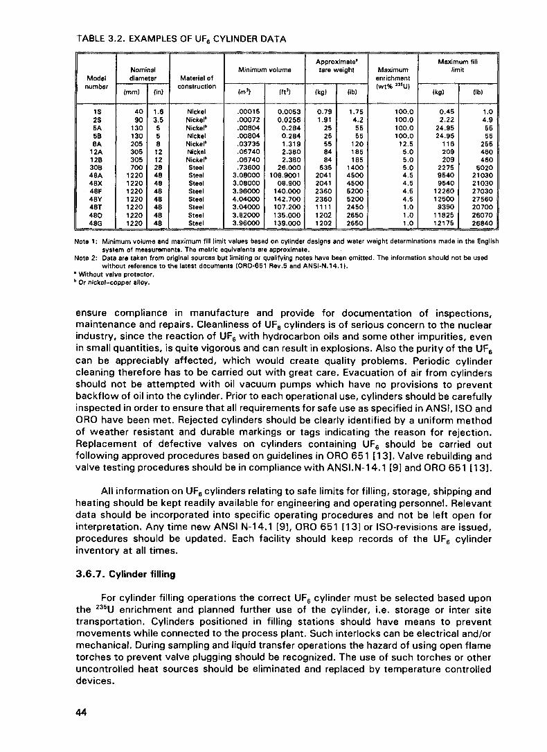
TABLE 3.2. EXAMPLES OF UFR CYLINDER DATA
Modelnumber
1S2S5A5B8A
12A12B30B48A48X48F48Y48T48048G
Nominaldiameter
|mm)
4090
130130205305305700
1220122012201220122012201220
(in)
1.63.555812122848484848484848
Material ofconstruction
NickelNickel"Nickel"NickelNickel"NickelNickel"SteelSteelSteelSteelSteelSteelSteelSteel
Minimum volume
(m3)
.00015
.00072
.00804
.00804
.03735
.06740
.06740
.736003.080003.080003.960004.040003.040003.820003.96000
(ft3)
0.00530.0256
0.2840.2841.3192.3802.380
26.000108.9001
08.900140.000142.700107.200135.000139.000
Approximate*tare weight
(kg)
0.791.91
2525558484
6352041204123602360111112021202
(Ib)
1.754.25555
120185185
14004500450052005200245026502650
Maximumenrichment|wt% 235U)
100.0100.0100.0100.0
12.55.05.05.04.54.54.54.51.01.01.0
Maximum filllimit
(kg)
0.452.22
24.9524.95
116209209
227595409540
12260125009390
1182512175
(Ib)
1.04.95555
255460460
502021030210302703027560207002607026840
Note 1: Minimum volume and maximum fill limit values based on cylinder designs and water weight determinations made in the Englishsystem of measurements. The metric equivalents are approximate.
Note 2: Data are taken from original sources but limiting or qualifying notes have been omitted. The information should not be usedwithout reference to the latest documents (ORO-651 Rev.5 and ANSI-N.14.1).
• Without valve protector." Or nickel-copper alloy.
ensure compliance in manufacture and provide for documentation of inspections,maintenance and repairs. Cleanliness of UF6 cylinders is of serious concern to the nuclearindustry, since the reaction of UF6 with hydrocarbon oils and some other impurities, evenin small quantities, is quite vigorous and can result in explosions. Also the purity of the UF6
can be appreciably affected, which would create quality problems. Periodic cylindercleaning therefore has to be carried out with great care. Evacuation of air from cylindersshould not be attempted with oil vacuum pumps which have no provisions to preventbackflow of oil into the cylinder. Prior to each operational use, cylinders should be carefullyinspected in order to ensure that all requirements for safe use as specified in ANSI, ISO andORO have been met. Rejected cylinders should be clearly identified by a uniform methodof weather resistant and durable markings or tags indicating the reason for rejection.Replacement of defective valves on cylinders containing UF6 should be carried outfollowing approved procedures based on guidelines in ORO 651 [13]. Valve rebuilding andvalve testing procedures should be in compliance with ANSI.N-14.1 [9] and ORO 651 [13].
All information on UF6 cylinders relating to safe limits for filling, storage, shipping andheating should be kept readily available for engineering and operating personnel. Relevantdata should be incorporated into specific operating procedures and not be left open forinterpretation. Any time new ANSI N-14.1 [9], ORO 651 [13] or ISO-revisions are issued,procedures should be updated. Each facility should keep records of the UF6 cylinderinventory at all times.
3.6.7. Cylinder filling
For cylinder filling operations the correct UF6 cylinder must be selected based uponthe 235U enrichment and planned further use of the cylinder, i.e. storage or inter sitetransportation. Cylinders positioned in filling stations should have means to preventmovements while connected to the process plant. Such interlocks can be electrical and/ormechanical. During sampling and liquid transfer operations the hazard of using open flametorches to prevent valve plugging should be recognized. The use of such torches or otheruncontrolled heat sources should be eliminated and replaced by temperature controlleddevices.

Cylinder weights should be carefully monitored during filling operations to avoidoverfilling. Cylinders that are accidentally overfilled should be clearly identified by weatherresistant and durable markings or tags. An overfilled cylinder should have the excess UF6
removed as soon as possible following approved procedures (see also para. 3.5.5"Transferring of UF6 from cylinder to cylinder"). This operation should be conductedwithout heating (if possible) to avoid the possibility of rupture, if possible, overfilledcylinders should not be removed from a facility until the overfilled condition has beencorrected.
3.6.8. Cylinder heating
Before cylinders are heated, they should be inspected and both the weight of the UF6
and the internal cylinder pressure should be verified. Both values must be within safe limits.Heating of cylinders which are overfilled may result in rupture of the cylinder, and releaseof the UF6 as a superheated liquid. Heating of cylinders shall only be performed bycontrolled heat sources. Temperatures should never exceed the cylinder designtemperature. Localized heating of cylinders should never be practised because of theassociated rupture hazard. During heating, the cylinder valve shall be open and cylinderpressure will be monitored. UF6 cylinder heating facilities should have the capability ofcontaining UF6 releases within a secondary containment; they should be built as autoclaves(see Figure 3.20). If this capability does not exist, then assessments should be completedon probable UF6 release accident scenarios to identify consequences to personnel andenvironment.
3.6.9. Plant components and connecting lines
Fixed and flexible connecting lines (such as "pig tails") should be designed, fabricatedand inspected to accepted standards. Connecting lines must be inspected by qualifiedpersonnel before each use (see Figure 3.21). Upon installation of plant components andconnecting lines, leak testing and functional testing should be carried out. Depending ontemperature and pressure of the UF6 contained in process lines, it may be necessary to
FIG. 3.20. Cylinder heating.
45

FIG. 3.21. UF6 cylinder connected to heated pigtail.
apply heat tracing to avoid unwanted liquefaction and/or solidification of UF6. Wheneverpossible trace heaters should be designed to be self limiting rather than depending upona control device. Uncontrolled localized heat sources, such as torches, must never beapplied to connecting lines or other components containing liquid or solid UF6.
Care should be exercised in the selection of pumping systems for evacuation of UF6
process plant and UF6 cylinders. Vacuum pumps containing hydrocarbon oil should beequipped with an oil backflow reservoir of sufficient volume or a chemical trap (e.g.activated carbon) to prevent oil entering into the UF6 system in the event of pumpstoppage.
3.7. OTHER SAFETY CONCERNS
3 . 7 . 1 . Conversion and reconversion operations
There are numerous safety considerations which must be addressed. Theseconsiderations are combinations of radiological, industrial, chemotoxic and environmentalsafety. Since the detailed safety analyses of handling and processing UF6 are covered inSection 3.6, this section will attempt to cover the safety concerns in general. This is notintended to be all inclusive but to give the reader some ideas as to the variety ofconsiderations required.
3.7.1.1. Design and equipment
It is very important that the construction materials for processing equipment arecompatible with the process. Temperature and pressure conditions must be considered. Anexample is the use of 300 series stainless steel for nitric acid services or monel forhydrofluoric acid services.
Design of the equipment is another important safety factor. Adequate fume or dustremoval systems with provisions for maintenance must be included when the process is
46

being designed. All connections for acid fume removal systems must be welded orwater-tight to avoid any leakage. Whenever practical, the design should consider"in-leakage" vs "out-leakage", i.e. the design should "pull" rather than "push" any fumesor dust through a duct.
An appropriate alarm system to detect any abnormalities in the process system isdesirable. There are two types — one being process alarms and the other being thedetection in the working atmosphere. Examples of the types of alarms are gaseousdetectors for hydrogen, fluorine and hydrofluoric acid and conductivity alarms for liquids.Also, redundant containment is widely used for environmental and personnel protection andis recommended. Continuous monitoring systems in plant and on all emission streams isrecommended as part of the plant design.
3.7.1.2. Process chemicals
These operations take place within a chemical processing plant with its chemicalhazards along with the radiological concerns. Extensive literature is available for the variouschemicals used in the processes. Some major ones are addressed in this section toillustrate some of the requirements for safety.
The principal chemicals used in the purification and conversion operations are nitricacid, sulphuric acid, tributyl phosphate, lime, fluorine, hydrogen, hydrofluoric acid andpotassium hydroxide. Material safety data sheets are available from vendors for most ofthese chemicals. The properties of HF and UF6 have been previously covered in Chapter 2.
Fluorine
Fluorine is the most hazardous chemical used in these processes, being both toxicand corrosive. Many materials combine with and burn spontaneously in fluorine as it is themost electronegative and easily the most reactive element known. Fluorine is a pale,green-yellow gas with a penetrating odour similar to ozone. Its odour is so intense it canbe detected by the sense of smell at concentrations below the threshold limit value (TLV)of 0.1 ppm. Fluorine attacks skin causing a thermal burn and by reaction with moistureliberates HF (Reference 'Fluorine — The First 100 Years', Elsevier Science Publishing Co.Inc., 1986)115].
Electrolyte
The electrolyte used to generate fluorine is usually based upon KF.2HF prepared byaddition of anhydrous HF (AHF) in liquid form to potassium hydrogen fluorine (KHF2). AHF(boiling point 19°C) can give rise to serious skin burns and tissue damage. The longer theexposure and the thinner the skin, the more rapidly do lesions appear. The subsequentpains and white necrosis can be severe. Treatment for HF burns has been based uponinjection of sterile 10% calcium gluconate or topical application of iced alcoholic/aqueoussolutions of quaternary ammonium compounds. In general, ingestion of fluorides must becontrolled because of toxicity. A lethal quantity is 5-10 g of sodium fluoride. A thresholdlimit value for airborne particulate fluoride of 2.5 mg/m3(F) has been proposed.
3.7.1.3. Personnel
For personnel protection, standard safety equipment is adequate in these processplants. Protective clothing, neoprene gloves and suits, self-contained breathing equipment,acid proof goggles, face shields, and safety shoes and helmets are worn when needed. Allprotective clothing must be clean and free of hydrocarbons since HF and F2 will react withthe hydrocarbons and thus could penetrate the protective equipment. Because hazards
47

exist from the chemicals and radioactivity, extensive training of all employees is veryimportant. The training should be comprehensive, including indoctrination and recognitionof chemical and radiological hazards. Other specialized training is to be provided asnecessary. To ensure proper radiological protection, dosimeters must be worn by eachperson while in a process area. To minimize exposure, good housekeeping is essential inmaintaining low radiation and airborne contamination levels and general safety.
The medical control programme required in the uranium processing plant is similar tothat in the heavy metal industry. Usually, the programme includes a pre-employmentexamination to detect pulmonary, renal or haemotological disease. Also periodic scheduledphysical examination is carried out to monitor the health of the employees. Routineurinalysis for uranium is performed to determine the exposure level of the employee.
The following guidelines provide radiological and chemical protection to personnelinvolved with the handling and storage of UF6 cylinders.
(a) On receipt, UF6 cylinders should be monitored for radiation and contamination. UF6
cylinders which exceed established radiation and other guidelines should be identifiedand isolated from other cylinders. Corrective actions should be initiated.
(b) A personnel monitoring programme should be established to assure that personnel donot receive excessive radiation exposure.
(c) Personnel handling UF6 cylinders should have access to respiratory protectiveequipment that provides chemical protection from UF6 and HF and from particulatesin the event of a UF6 release. Other protective equipment should include chemicalprotection suits which are resistant to UF6 and HF.
(d) In the event of a cylinder rupture or a UF6 release, personnel without protectiveequipment should promptly evacuate the area to avoid any contact with the UF6 orHF. Assembly points should be established upwind.
The guidelines outlined previously for radiological and chemical protection topersonnel involved with handling UF6 (both monitoring and emergency) also apply to UF6
storage.
3.7.2. Safety considerations — UO3 to UO2
The principal safety concerns in the UO3 to UO2 reduction area are the handling ofammonia, hydrogen and hazards of high operating temperatures. The safe handling ofhydrogen is primarily concerned with preventing the formation of an explosive mixture withair. The following are examples of recommended safety measures:
Ensure the integrity of seals at the inlet and outlets of the reactor system.Purge with inert gas and use a seal pot to avoid air entering the reduction reactorsHydrogen analyzers are to be located near equipment containing hydrogen.All major equipment should have a design pressure sufficient to withstand anexplosion.Sprinklers should be installated in the UO3/UO2 baghouses in cases of fire.Spark detectors should also be installed in the inlet and outlet ducts from thebaghouses.
3.7.3. Safety consideration - Ftuorination of UF4 to UF
In this process hazards are created by handling F2, HF, UF6 and UF4. Gaseous F2, HFand UF6 are found in the UF6 reactors and UF6 filter areas as well as in the process piping.
48

FIG. 3.22. Cells for F2 generating.
When maintenance work is to be performed on any process equipment, lines or processvents, care must be taken to ensure that they have been previously isolated and purged.UF4 dust is a chemical hazard as well as a radiological hazard. Exposure can result indamage to the kidneys, therefore respiratory equipment must be used at all times there isa potential for UF4 to become airborne. The UF6 may also contain fluorides which, incontact with the skin will produce HF, (possible burn) therefore proper personal protectionmust be worn. There are also some radiological concerns in the reactor areas. Externalexposures in the form of alpha, beta and gamma radiation can be obtained from the filters,headers, valves, reactors discharge lines, and ash collectors.
3.7.4. Safety — Cell maintenance
3. 7.4.1. Cell removal
The principle hazards associated with a fluorine cell are of electrical and chemotoxicnature. Before starting to work on a cell, ensure that the cell has been electrically isolatedand that the rectifier has been locked and tagged off (see Figure 3.22). When taking a cell"off-line" purge the cell using N2 before isolation from the fluorine/hydrogen headers.Protective gloves and dust masks must be worn when cleaning out headers. The carryoveris electrolyte and it contains HF.
3.7.4.2. Electrolyte transfer
This step requires the presence of a safety standby operator and the use of aprotective suits, respiratory protection, face shields and gloves because of the HF contentin electrolyte. Fumes will be generated during this operation which could cause burns ifskin is exposed or fumes are inhaled.
49

3.7.5. Safety - Fluorine and fluorine passivation
The presence of fluorine in the atmosphere can be monitored but is readily noticeableat very low concentrations (1 mg/m3) because of its characteristic odour. All leaks mustbe traced and immediately stopped. Fluorine is toxic and is an extremely strong oxidizingagent. Care must be taken that the equipment used to transport and store this gas isproperly prepared. The corrosion resistance of a metal towards fluorine is based on theformation of a surface fluoride layer which protects against further attack by fluorine. If theequipment in which fluorine is to be used is not properly cleaned and passivated beforeuse, reactions of the fluorine with metals can take place and can lead to the burning of thevalves, manometers, reactors and the lines. The following measures are absolutelyessential. All parts must be very carefully cleaned of impurities and degreased. The solventis then completely removed by drying, and the equipment flushed with nitrogen. After thesystem has been completely checked for leakages, it is passivated. For this operation slownitrogen flow is passed through the apparatus, to which an increasing proportion of fluorineis added, until finally pure fluorine flows into the apparatus. All valves are closed and timeallowed for passivation. When sufficient passivation has been attained the apparatus isready for operation. An alternative method is to evacuate the system and allow the fluorineto flow into the system slowly, till atmospheric pressure is reached. The fluorine is left inthe equipment for some hours for passivation. Improved stability results if the system canbe heated to a controlled temperature.
Qualified and well-trained staff should be employed for work with fluorine. Personalprotection equipment should be worn at all times. If work is carried out with equipmentcontaining fluorine, gloves made of neoprene, protective headwear with face-shield ofplastic and protective clothing must be worn. Furthermore, all the standard safetymeasures for the handling of highly toxic gases must be applied. In emergency situations,self contained breathing apparatus is required. All protective clothing and equipment mustbe clean and free of hydrocarbons.
3.7.6. Safety of reconversion operations of UF6 to UO2, to U3O8 or to UF4
Safety considerations for reconversion operation of UF6 to either UO2, to U3O8 or toUF4 are mostly covered by those for concentrate - UF6 conversion operation described inSection 3.4.1. Similar safety concerns are UF6 cylinder heating, and gas phase reactionsusing H2 for both wet and dry processes. HF is recovered within the dry process. Thedetails of these items are described in 3.4. HF is recovered in the dry conversion processat concentrations between 40 to 70 wt% at which it poses a corrosion hazard. In handlingthis material great care must be taken in the selection of materials and in the measures toprotect personnel.
3.7.7. Safety - Liquid effluent
In the liquid effluent treatment area, the hazards are mostly associated with chemicalhandling. Personal protective equipment such as eye protection and rubber gloves arerecommended. Radiological hazards are minimal in this area except when UF6 filters arecleaned. Normally, these filters are stored until they decay to a safe handling level.However, radiation checks should be part of a routine procedure before they are handled.Workers should wear personal dosimeters whenever the filters are cleaned.
50
Chapter 4
TRANSPORT
This chapter does not specify additional regulations for UF6 transport, nor does itmodify those used successfully for many years. Regulations applicable to UF6 transport arepublished by the IAEA in its Regulations for the Safe Transport of Radioactive Material(Safety Series No. 6), the supplements to the Transport Regulations and its supportingdocuments consisting of advisory and explanatory material which should be consulted [16].For further information on the development of these regulations see Sections 4.8 to 4.10.
4 . 1 . GENERAL REGULATIONS FOR THE SAFE TRANSPORT OF RADIOACTIVE MATERIAL
UF6 transport may be classified under two headings:
transport within a nuclear site, by trained and qualified personnel, using specializedequipment, under national licensing arrangements;
carriage on public transport networks by personnel who are not specially trained inthe handling of packages of nuclear materials and making use of either specialized orstandard vehicles covered by IAEA Safety Series No. 6 [16].
The first category involves less risk to the public and the environment than does thesecond. The primary reasons for this are shorter distances and no accessibility of the publicto the site. The second category, involving greater risk, concerns transport betweenprocessing establishments which may be far apart within a country or between twocountries. When being transported the design of the entire package offers the protection(see Figure 4.1). The IAEA Regulations for the Safe Transport of Radioactive Material(Safety Series No. 6) provide standards for ensuring a high level of safety of people,property and the environment against radiation and criticality hazards as well as othereffects associated with the radioactive properties of materials. The basic requirements are:
- containment of radioactive material;control of radiation emitted from the package; and
- criticality prevention.
For meeting the basic requirements and the declared purpose of the Regulations,effective quality assurance and compliance assurance programmes are required. Theseensure, for example, that:
appropriate and sound packages are used,the activity of radioactive material in each package does not exceed the egulatoryactivity limit for that material and that package type,
- the radiation levels external to, and the contamination levels on, surfaces of packagesdo not exceed the appropriate limits,packages are properly marked and labelled and transport documents are completed,the number of packages containing radioactive material in a conveyance is within theregulatory limits,
- packages of radioactive material are securely stowed in conveyances and are storedat a safe distance from persons and photosensitive materials,only those transport and lifting devices which have been tested are used in loading,conveying and unloading packages of radioactive material, andpackages of radioactive material are properly secured for transport (see Figure 4.2).
51

FIG. 4.1. Outer protective packaging NCI-21PF-1 (Nuclear Containers Inc.).
The control of the transport of radioactive materials may be necessary also for otherreasons, e.g. safeguards control and physical protection of nuclear materials (seeFigure 4.3).
4.2. THE SPECIAL CASE OF UF6
For radioactive materials having other dangerous properties, the regulations ofMember States, modal conventions and agreements, and other relevant documents ofinternational organizations need to be applied. Generally, the other dangerous propertiesare controlled as subsidiary hazards. However, in the specific case of uranium hexafluorideat low enrichment levels, the subsidiary chemotoxic hazards generally override theradiological consequences (see Chapter 3). These chemical properties, combined with UF6
radiological characteristics are not adequately covered under existing IAEA and UnitedNations recommendations. This situation is being corrected (see Section 4.4 below).
4.3. PRESENT PRACTICE FOR UF6 TRANSPORT
The existing IAEA recommendations for UF6 transport packages are summarized inTable 4 . 1 . This information is derived from Safety Series No. 6, Regulations for the SafeTransport of Radioactive Material [16], and the table numbers refer to the relevantparagraphs. These requirements do not consider the chemotoxic properties of UF6. Also,the table does not consider the additional radiological hazards of recycled material.Additional advisory material is available in Safety Series No. 37, Advisory Material for theIAEA Regulations for the Safe Transport of Radioactive Material [17J, and in Safety SeriesNo. 7, Explanatory Material for the IAEA Regulations for the Safe Transport of RadioactiveMaterial [18].
52

FIG. 4.2. D0T-21-PF-1A outer protective packaging.
FIG. 4.3. Ux-30 outer protective packaging (Nuclear Packaging Inch
53

TABLE 4 .1 . REQUIREMENTS IMPOSED ON UF6 TRANSPORT PACKAGES BY IAEA SAFETY SERIES No.6(Numbers in parentheses indicate relevant paragraph numbers from Safety Series No. 6 116])
Uraniumenrichment% of U-235
<£0.72%
>0.72% to1.0%
>0.72%
> 1.0% to5.0%
>5.0%
Maximumcontents(g of U-235)
(b)
(b)
15g(560a)
(b) (f)
(f)
Materialclassification
LSA-I(c)
LSA-Ii (d)
LSA-i! (e) ifenrichment < 5 % ; ifenrichment >5%,LSA-N (e) if specificactivity £ 105 Bq/g,otherwise not LSA
LSA-Ii (e)
LSA-H (e) if specificactivity £ 105 Bq/g,otherwise not LSA
Maximumradiationlevel
Fissilematerialclassification
EXCEPTED PACKAGES -
10 mSv/h3 m fromunshielded
if LSA-I orLSA-1!(422), and2 mSv/h at
packagesurface ifnot underExclusiveUse (433),or10 mSv/hat packageciirfapp if
underexclusiveuse (434)
Non-fissile
Fissile
Fissile
Fissile
Fissile
Fissilepackagingrequirements
UNnumber(a)
SEE TEXT, SECTION
None
FissileExcepted(560)
FissileExcepted(560)
Fissile (559,561-568) (g)
Fissile (559,561-568) (g)
2978
2978
2978
2977
2977
Packagingrequirements
IP-1 (426,518)
IP-2(426,519)
IP-2 if LSA (426,519, 560), orType A if notLSA (524-538)
!P-2 (426,519);and Fissile (559)
IP-2 if LSA(426,519), or, ifnot LSA, Type A(524-538) orType B (549-556 or 557-558); and Fissile(559)
Labelling &documentationrequirements
(436-453)
(436-453)
(436-453)
(436-459)
(436-459)
Approvalrequirement
None
None
None
Multilateral(710)
Multilateral(710)

(a) UN number is used internationally to assist hazard identification in emergency response (see Appendix I of Ref. [16]).
(b) Controlled by unshielded materiai radiation level at 3 m (422) (see para. 422 of Ref. [16]).
(c) Natural and depleted solid unirradiated uranium is classified as LSA-I (see para. 131(a)(ii) and (iii) of Ref. [16]).
(d) LSA-i cannot be fissile material (see para. 131 (a)(iii) of Ref. [163). Although the package containing uranium enriched to a maximum of 1 % should be regulated asa non-fissile material package the radioactive material is still fissile. Therefore, it is classified LSA-ll(e).
(e) The specific activity limit for solid LSA-ll is (see para. 1 31 (b)(ii) of Ref. [16]): 10"4A2/g. Up to 5% enrichment level (including) the A2 value is unlimited. Above 5%enrichment level the A2 value is 10 3TBq; thus LSA-II limit is: 10'4 x 10"3 TBq/g = 10 7 TBq/g = 105 Bq/g. UF6 enriched to levels where the specific activity exceeds105 Bq/g cannot be classified as ISA-Ill because the requirement of para. 131 (c)(ii) of Ref. [16] is not fulfilled.
(f) Controlled by package design.
(g) Fissile material shall be packaged and shipped in such a manner that subcriticality is maintained under normal conditions of transport and in accidents. Fordemonstrating this the packages are required to be tested as specified in paras 619-624,626-628and 631 -633or 619-624and 629 (more limiting combination)of Ref. [16].
O1

4.4. NEW RECOMMENDATIONS FOR UF6 TRANSPORT
The IAEA recognizes the chemotoxic properties of UF6 and has taken on the task ofdeveloping recommendations to provide protection during the transport of UF6. Theserecommended requirements were published in IAEA-TECDOC-608 [19]. The provisions willbe subject to further review by Member States and are intended to be included into theIAEA Safety Series Regulations No.6 in its 1996 revised edition. The requirements, insofaras they affect cylinder design specifications, have been included in the InternationalStandard ISO/7195 [14] which closely follows ANSI N14.1-1987 [9] but requirescompliance with IAEA recommendations and includes cylinders other than to United Statesspecification.
4.5. URANIUM HEXAFLUORIDE PACKAGES
A package for the transport of UF6 means the packaging with specified contents aspresented for transport. Packaging is used to mean the assembly of the cylinder serviceand structural equipment.
4.5.1. Cylinders
Cylinders used for transport purposes also serve as process vessels during filling andemptying operations. The types of cylinder most frequently used are listed in Chapter 3.The design and manufacturing specifications of UF6 cylinders are covered in detail in suchpublications as ANSI N 14.1 [9], and ISO/7195 [14] to which reference should be made.
4.5.2. Outer packaging
An outer protective packaging is used to provide additional protection for criticalitypurposes, for thermal protection and for extra resistance in potential accident conditions.Figure 4.4 shows 48 inch cylinders with outer protective packaging. A breach of anunprotected cylinder containing enriched UF6 could allow ingress of water which couldresult in a criticality incident. Approved designs of outer protective packaging [e.g. DOT21-PF1 Series (see Figure 4.2), UX-30 (see Figure 4.3)] ensure that ingress of water isprevented while providing thermal insulation and physical protection. Proper maintenanceof the outer protective packaging is essential to ensure the integrity of the package as afire and shock resistant housing. The outer protective packaging shall be kept structurallysound, provide a tight seal between the cover and base, and be protected from damageto the insulation by moisture. The minimum inspection and maintenance requirements arelisted in ANSI N 14.1 (1987) [9]. National and international criteria for licensing and testingshould be strictly observed.
4.5.3. Stowing and fastenings for transport
Stowing and fastening represent an important factor under the heading "safety intransport". Stowing and fastening materials must be suited to both the package and thetransport vehicle. They must hold the shipment components together and act as ashock-absorber if the fastenings break during an accident.
There are two categories of devices:
rigid devices,sliding devices.
Both categories can be used in the transport of all UF6 containers. The rigid devices,however, are normally used for light weight packages (types 5, 8, 12, 30 Cylinders)
56

FIG. 4.4. 48 inch cylinders loaded in outer protective packaging.
equipped with outer protective packagings. These devices are intended to solidly securethe container to the floor or wall of the vehicle and to prevent any movement of the loadduring transport. They must resist the force of an emergency stop of a road vehicle or thebuffeting of a rail car. The sliding devices are used for transport of 48 inch type cylindersby rail. These devices retard and stop, the longitudinal movement of the load after asudden shock within a given distance. Apparatus for transportation may be chosen froma large variety of options. The most often used are:
flats (closed or open),wooden or metal cradles,pallets,various jigs, frames, spreaders, fasteners, most often made of wood,chains, straps, ropes, tensioners, bolts, pins, serving to fix the container and itsbearer to the transport vehicle.
4.6. OTHER TRANSPORT CONSIDERATIONS
Apart from the safety provided by the design of the package itself, transport safetyrequires:
effective organization of transport,careful choice of the carrier and the means of transport,an appropriate system used for fixation of the packaging,various measures taken by the people responsible for transport.
57

The accumulated experience of all the parties involved is of great value in thesematters. For example, a set of regulations, however comprehensive, cannot provide thecriteria necessary to choose the 'right' transporter. Nor can it show the most effectivemeans of fixation which is suitable both for the packaging and the vehicle.
4.6.1. Organization of transport
The transport organization must comply with all the administrative and legalrequirements. The procedures in each country are different and depend on the regulationsof the country.
4.6.2. The choice of carrier
The carrier is an important factor in the transport of UF6, particularly when severalmeans of transport (such as road, rail and sea) are used. The carrier's importance increaseswith the distance and the number of different types of transport used. Consequently, thecarrier's ability, organization and experience must indicate that he can carry out the task.Economic factors cannot be the only criteria used to select a carrier. Their installations andrepresentation and their experience, equipment and the qualification of their personnel arealso important. Many countries require companies wishing to engage in transport of nuclearmaterials to be licensed by a government ministry. The carrier and consignee shouldtogether choose the type of transport to be used. National authorities require that civilauthorities who would be involved in case of accident, be informed. This responsibility maybe delegated to the carrier if permitted by regulations.
4.7. TRANSPORT DOCUMENTS OF INTERNATIONAL ORGANIZATIONS
Recommendations on the Transport of Dangerous Goods, Committee of Experts onthe Transport of Dangerous Goods, United Nations (UN)), New York.Technical Instructions for the Safe Transport of Dangerous Goods by Air (Tl),International Civil Aviation Organization (ICAO), Montreal.Dangerous Goods Regulations, International Air Transport Association (IATA),Montreal.International Maritime Dangerous Goods (IMDG) Code, International MaritimeOrganization (IMO), London.Universal Postal Convention of Rio de Janeiro 1979, Universal Postal Union, Bern.
4.8. TRANSPORTATION DOCUMENTS OF REGIONAL OR NATIONAL ORGANIZATIONS
European Agreement Concerning the International Carriage of Dangerous Goods byRoad (ADR) and Protocol of Signature, United Nations Economic Commission forEurope (ECE), Geneva (1957).
- R6giement international concernant le transport des marchandises dangereuses parchemins de fer (RID), Convention Internationale Concernant le Transport desMarchandises par Chemins de Fer (CIM), Office Central des Transports Internationauxpar Chemins de Fer (OCIT), Berne.Regulations for the Transport of Dangerous Goods on the Rhine (ADNR), CentralCommission for the Navigation of the Rhine (CCNR), Strasbourg.European Provisions Concerning the International Carriage of Dangerous Goods byInland Waterway (ADN), Draft, United Nations Economic Commission for Europe,Geneva.Regulations for the Transport of Radioactive Substances, Annex 4 to the Agreementon International Railroad Freight Traffic (SMGS), Railroad Cooperation Organization(OSZhD), Warsaw.
58

Regulations for the Safe Transport of Spent Fuel from Nuclear Power Plants of CMEAMember Countries — Transport by Rail, Council for Mutual Economic Assistance(CMEA), Moscow.Regulations of the US Nuclear Regulatory Commission (NRC), the US Department ofEnergy (DOE) and the US Department of Transportation (DOT).
4.9. PHILOSOPHY OF THE REGULATIONS
The basic principle underlying the IAEA's regulations is that protection against thehazards of radioactive material in transport should be provided by the packaging in whichit is carried. The consignor of the radioactive material has primary responsibility for safetyand must declare in the transport documents that it is packed, marked and labelled inaccordance with the applicable regulations. This ensures that the person most likely tohave the necessary knowledge of the special hazards presented by the radioactive material,is responsible for providing safety in the transport.
The carrier has a lesser degree of responsibility and must take appropriate precautionsto protect workers and the public during transit. Where the hazard of the material beingtransported requires it, the protection afforded by the packaging must remain effective,even under severe accident conditions. For more hazardous contents, an independentreview and approval of the transport package design by appropriate national authorities isrequired. The regulations also require quality assurance measures to avoid inadvertentnon-compliance with safety features and appropriate emergency response arrangementsto deal with the consequences of accidents or incidents. The IAEA's regulations seek tocontrol the impact of the transport of radioactive material on workers, members of thepublic and the environment. The record, however, speaks for itself. In more than 40 yearsof transportation, there have been no known deaths or injuries due to the radioactivenature of material being transported under the provisions of the regulations. In principle,the IAEA's regulations control radiation hazards and, where these are significant, wouldalso cover subsidiary chemical risks. Where the radioactive hazard is low (see Table 2.2),other regulations would normally apply. However, uranium hexafluoride is unique. BecauseUF6 is carried solely for the nuclear energy industry, it is appropriate for the IAEA to be thefocal point for setting formal requirements. IAEA-TECDOC-608 [19] includes therecommendations for inclusion in the 1996 Edition of the Transport Regulations.
59

Chapter 5
STORAGE OF URANIUM HEXAFLUORIDE
5.1. INTRODUCTION AND GENERAL CONSIDERATIONS
Storage of UF6 both short-term and long-term occurs at many locations around theworld. Short-term storage safety considerations involve criticality, inventory control, andsafe handling. Long-term storage safety considerations include those above pluscontainment (container integrity). Feed stock of enriched material may experience extendedpauses in its flow through the nuclear fuel cycle. Depleted UF6 deserves special attentionconcerning storage because large amounts of this material are generated at enrichmentplants and it is then stored for very long periods. Figure 5.1 shows a typical UF6 stagingarea. It is assumed that UF6 is stored as a solid in approved cylinders such as thosedescribed in ORO-651 [13] and ISO-2195 [20] (for examples see Table 3.1). Many factorsare common to both short- and long-term storage: stacking and spacing considerations(criticality, radiological, and mechanical), accountability, security, safety, chemical activity,quality control, quality assurance, and emergency planning. For extended storage theselection and qualification of a storage site, cylinder maintenance, monitoring, control andinspection, accountability, and security, and the monitoring of corrosion of containmentvessels are all important. The factors which affect short-term storage will be describedseparately when they differ significantly from long-term storage practices or requirements.
FIG. 5.1. Typical UF6 cylinder staging area (before movement to long term storage pad).
61

5 . 1 . 1 . General criteria for UF6 storage
All cylinders used for the storage of UF6 should be individually equipped with a dataplate in accordance with ANSI, 0R0 and ISO-7195 [14] specifications. All cylinder storageshould be supported by an accountability records system to identify cylinder contents aswell as to maintain a history of each cylinder. This system should include the following:
Complete fabrication data (drawings, materials of construction, applicable codes,standards deviations, date of fabrication, and certified volume when available);Test data;Transportation experience;Inspection results;
- IAEA competent authority certificates, domestic approvals, etc.;Maintenance and repair records.
All cylinders scheduled for storage of UF6:
Should be equipped with approved valves and plugs that are properly installed;Should be secured from unauthorized access;
- Should have all defects, deviations, discrepancies, dents, and damage identified(defective or damaged cylinders should be set aside for repair or other action asappropriate);Should have identified internal contaminants (i.e., non-UF6) that are above UF6 purityspecifications.
Preferably UF6 cylinders should be grouped for storage in arrays according to thefollowing criteria:
Cylinder model;235U enrichment;Scheduled storage period;
- Final destination of material;- Contents (i.e., full, empty, clean, etc.);
Accessibility requirements.
Fire prevention is of particular importance for UF6 storage areas since fire representsan opportunity for significant material release. Flammable materials should not be storedin the proximity of cylinders. Access to cylinder storage areas should be restricted. Thisrestriction should apply to storage of all cylinders, empty as well as filled. Figure. 5.2shows model 48Y cylinders for storing UF6.
5.2. ORGANIZATION
UF6 storage is an integral part of UF6 operations. Each storage facility for UF6 shouldbe organized to ensure that all responsibilities are appropriately assigned. The organizationshould include or interface with the following activities and report to the facility manager:
- AdministrationProcurementOperationsMaintenanceNuclear materials managementSafety and Health• Nuclear criticality safety• Radiological safety- Industrial safety• Safety analysis
62

FIG. 5.2. 48Y cylinders for storing UF6.
Transportation/traffic• On-site• Off-siteQuality assurance/quality control• Inspection• Tests.
5.3. QUALITY ASSURANCE AND QUALITY CONTROL ASPECTS OF UF6 STORAGE
A quality assurance (QA) assessment or plan for a UF6 storage facility should addressmaterial handling, cylinder safety, and storage monitoring. The assessment should considerhealth, safety, and monetary impacts of system failures such as cylinder leakage due tocorrosion, handling damage, or damage from earthquake, storm, or other external forces.Cylinder inspections; storage monitoring; maintenance of auxiliary facilities for weighing,filling, and emptying; cylinder handling; waste management; emergency management;personnel training; and preparation and maintenance of operating procedures should alsobe included in a quality assessment.
5.4. SITE SELECTION AND CRITERIA
5.4.1. Selection
The choice of a site for the safe and secure storage of UF6 cylinders is oftenpredetermined by the location of processing facilities and the economics and safety of
63

additional transport movements. The physical location can be characterized by factors suchas local topography, hydrology, demography, geology, seismology, and climate. Associatedwith the site will be buildings and structures housing equipment used in receipt andstorage, and the appropriate transport infrastructure. The site will usually be capable oftransferring UF6 in both the liquid and the gas phases. A storage site will require provisionof services for personnel exposure protection and safety, QA, surveillance, inspection,maintenance, and security.
The assessment of the impact of the location of the site on the environment shouldinclude consideration of natural phenomena and situations that could lead to an accidentalrelease of UF6, including low-probability events. The presence of adjacent sources ofatmospheric pollution can significantly affect storage acceptability. Exhausts fromchimneys, chemical stacks, and water cooling towers can influence the pH of rainfall orprovide particulate deposition which may accelerate cylinder corrosion rates. Thedegradation of cylinders will also be affected by coastal salt-bearing winds and the generalhumidity. Temperature variation, both diurnal and seasonal, must be considered in relationto UF6 physical properties and cylinder design criteria.
5.4.2. Site criteria
(a) Site selection should consider fire, earthquake, and damage from other phenomena.(b) The site should be well drained and should not be subject to casual flooding.
Capability for temporary holding and monitoring of runoff should be provided.Figure 5.3 shows a typical UF6 cylinder storage yard.
(c) The site should provide a stable surface for cylinder storage.(d) Site access should be restricted by walls or fences. Security measures should be
provided.(e) The site should be served by transportation facilities suitable for its needs.
FIG. 5.3. Typical UF6 cylinder storage yard.
64

(f) Reasonable containment of accidental releases of UF6 should be possible.(g) The site should have facilities for the transfer from one UF6 cylinder to another,
preferably in the gaseous phase.
5.5. EQUIPMENT AND CAPABILITY NEEDS FOR A STORAGE FACILITY
Maintaining a storage facility requires the concurrent maintenance of a range ofauxiliary support facilities. Capabilities required for UF6 cylinder storage include cylinderhandling equipment, a system for accountability, QA (including a mechanism to correctdeficiencies), and emergency response. Cylinders should be positioned on chocks. Cylinderhandling capabilities such as lifting fixtures and hardware, straddle carriers, forklifts,cranes, and specialized cylinder handling machinery are needed. Cylinder damage due tohandling activities and cylinder wall thinning due to corrosion processes may render acontainer unsuitable for transport. Therefore, capability to transfer from one cylinder toanother is needed. An alternative would be to have the capability of transporting rejectedcylinders to another site. The occasional need to change valves makes it necessary to havethe equipment and trained personnel to make such changes. Storage facilities for UF6 alsorequire leak detection equipment.
5.6. SECURITY
All UF6 storage facilities require security arrangements appropriate to the 235Uenrichment. The highest levels of security are required for 235U enrichments greater than20%.
Basic requirements for a security system for all UF6 storage are:
(a) The UF6 storage facility should be located inside a secure area;(b) Cleaned, emptied and new UF6 cylinders should also be stored in a secured area.(c) UF6 cylinders should be equipped with tamper-indicating devices during any period
when they are not in a secure area.(d) Access to UF6 storage areas should be limited to authorized personnel.(e) An appropriate communications system should be provided to ensure coordination
with the security, safety and emergency staffs.
5.7. CRITERIA APPLICABLE TO THE STORAGE OF CYLINDERS OF UF6 WHERECRITICALITY IS OF CONCERN
5.7.1. Administrative criteria
(a) Operations and storage arrangements shall follow established practices to preventaccidental nuclear criticality incidents1.
(b) Methods and practices shall be described in written procedures.(c) Personnel involved in cylinder movement and storage shall be fully aware of the
written procedures.(d) Compliance with the procedures shall be periodically verified by inspections.
5.7.2. Nuclear criticality safety practices
(a) Experimental data and/or validated computational results shall provide the basis forapproved storage arrays.
1 For example ANSI N16.1-1975, American National Standard for Nuclear Criticality Safety inOperation with Fissionable Materials Outside Reactors [21].
65

(b) Individual cylinders of UF6 shall be subcritical under conditions of total submersion inwater.
(c) The design, fabrication, and maintenance of facilities and structures for storage shallbe in accordance with good engineering practices. Analysis should show accidentalcriticality shall not result even if fire, flood, earthquake, and other natural phenomenado occur.
(d) The use of physical barriers including fixed storage positions, bird cages, etc., whichare sturdy and non-combustible are to be preferred to administrative controls topreclude criticality incidents during storage.
(e) A criticality detection and alarm system should be installed to alert personnel of anuclear criticality accident2.
5.7.3. UF6 enriched to greater than 5% 235U
The maximum 235U enrichment of the UF6 (see Table 5.1) should not be exceeded toensure cylinders are geometrically safe.
5.7.4. UF6 enriched from 1.0% up to 5% 235U
Moderation control is an acceptable method for nuclear criticality safety of UF6 forenrichments of 1.0% to 5% in large cylinders. By controlling the UF6 purity to not less than99 .5%, an equivalent moderating ratio expressed as an H/U = 0.088 would not beexceeded3 '4. If moderation control is not maintained (i.e. H/U > 0.088), then the UF6 in thisenrichment range must be stored and transported in smaller cylinders and packages (seeTable 5.2).
TABLE 5.1. MAXIMUM ENRICHMENT OF UF6 CYLINDERS FOR SEVERALCYLINDER DIAMETERS
Cylinder diameter
(in)
5
8
(cm)
12.7
20.3
Maximum enrichment{% U-235)
100.0
12.5
TABLE 5.2. MODERATION RATIO REQUIREMENTS FOR SEVERAL ENRICHMENT/CYLINDERDIAMETER COMBINATIONS
With moderationcontrol*
(H/U ratio)
<0.088
<0.088
Without moderationcontrol"
(H/U ratio)
>0.088
Cylinder diameter
(in)
30
48
12
(cm)
76.2
121.9
30.5
Maximumenrichment(% U-235)
5.0
4.5
5.0
• A moderation control ratio (H/U) of 0.088 would not be exceeded provided the purity of the UF6
exceeded 99.5%.
2 For example ANSI N16.2-1969, American National Standard Criticality Accident Alarm System[22].
3 ANSI N14.1-1987, American National Standard for Nuclear Materials - Uranium Hexafluoride,Packaging for Transport [9].
4 ORO-651, Rev. 5, Uranium Hexafluoride: Handling Procedures and Container Description,September 1987 [13].
66

5.8. CRITERIA APPLICABLE TO NON-FISSILE AND FISSILE EXCEPTED UF6
The storage requirements for UF6 with enrichment less than 1.0% follow the generalcriteria in Sections 5.1-5.6.
5.9. RADIOLOGICAL AND CHEMICAL CONSIDERATIONS
UF6 cylinders are often emptied by evaporation (see Chapter 3). Some radioactiveimpurities may remain and collect at the low points in the cylinder when the UF6 isevaporated. Thus "empty cylinders" may have a higher external radiation level (i.e., betaand gamma radiation) than full cylinders where the impurities are dispersed through the UF6
and are shielded to some extent (see Chapter 3). Uranium is also an alpha emitter.Personnel are protected from the alpha radiation and from the chemical properties of UF6
by the cylinder containment. The guidelines outlined previously (Chapter 3) for radiologicaland chemical protection of personnel involved with handling UF6 (both monitoring andemergency) also apply to UF6 storage.
5.10. EMERGENCY PLANNING (see also Appendix A)
In long-term storage of UF6, there may be a need to transfer cylinder contents toother cylinders. Transfer capabilities must therefore be available at the storage site for usewhen corrosion processes or mechanical damage make a transfer necessary. Proceduresshould be developed for each storage site for monitoring cylinder condition; for recording,storing, and retrieving such data; and for correcting deficiencies as they are identified.Procedures should also be developed for emergency situations, for example handlingaccidents, material releases, equipment failures, breaches of security, fires or other naturaldisasters, or man-made situations. Procedures should be developed to respond toaccidental material releases — from small leaks to major spills. Emergency procedures torespond to natural catastrophes such as earthquakes, fires, floods, and storms should beprepared. Emergency procedures should be prepared to respond to accidental or intentionaldamage by man, such as aircraft impact, vehicle damage, sabotage, theft, etc.
5.11. HANDLING, SHIPPING, AND RECEIVING CYLINDERS
Procedures should be prepared for all routine operations in UF6 storage includingcylinder cleaning and inspection, handling, storage, monitoring, and removal from storage.When a cylinder is removed from storage status (i.e. handled), procedures should befollowed to maintain accountability and to ensure that the cylinder meets the criteria forthe intended application or destination and that all safety, criticality, and environmentalconditions are satisfied. The cylinder selected for shipping should be tested to ensure thatthe pressure within the cylinder is below atmospheric. It should then be inspected toensure compliance with other handling and shipping criteria. When the cylinder is found tobe suitable for shipping, it can then be weighed and moved to a staging area for transferto a qualified carrier. Cylinders that do not meet internal pressure, external damage, orwall-thickness requirements should be rejected and identified. They should then besubmitted for corrective action or marked and set aside for later repair of defects ifappropriate.
5.11.1 . Storage status
The following steps should be followed before removing cylinders from storage.
(a) A cylinder should be given an internal pressure check to ensure below atmosphericinternal pressure.
(b) The cylinder should be inspected for cracks, bulges, dents, valve damage, and otherdefects.
67

(c) A weight determination should be made for reconciliation with the entry weight.(d) Valve protection should be provided, as appropriate.
5.11.2. Storage and transport interface
A staging area may be provided for UF6 cylinders between storage areas and transportand for their receipt upon arrival. Approved operating procedures should be established formoving cylinders within the site. These procedures should include UF6 cylinder preparationand inspection and UF6 cylinder receiving and inspection prior to storage. For off-sitetransport, requirements can be found in Chapter 4 and the documents referenced there.
5.12. ORIENTATION AND STACKING OF CYLINDERS
5.12.1. Natural and depleted material
In the storage of natural UF6, no special storage configuration is required for criticalitysafety. Since inventory control is generally by cylinder serial number, storage arrays willnormally be limited to double rows so that any cylinder is accessible to lifting equipment.The 30 and 48 inch cylinders must be stored horizontally with the valve in the 1 2 o'clockposition. The cylinder contents tend to redistribute themselves over time. If thisredistribution is not considered, for some types of lifting equipment (notably the H-framewith cables) can be operated outside of their safe load range with an eccentrically loadedcylinder. Long-term storage requires attention to such factors as cylinder support (chocks),visibility of the cylinder serial number, and physical condition of the cylinder (degrees ofrusting, valve condition, dents, or other physical damage). Arrays should have sufficientclearance between rows to permit inspection of both ends of each cylinder for monitoringthe progress of atmospheric corrosion, wall thinning, and other damage. Cylinders fornatural and depleted UF6 should be stored in orientations and arrays suited for the effectiveuse of handling equipment.
5.12.2. Fissile UF6
Enriched material is to be stored in cylinders of suitable geometry and/or with suitablemoderation control in order to meet criticality considerations. Storage arrays should permitclose visual access to the cylinder nameplate, valve, and support points as well as generalaccess to surfaces exposed to corrosion processes. The storage arrays should allow forease of removal of specific cylinders with a minimum of movement of other cylinders inthe array.
5.13. ACCOUNTABILITY AND INVENTORY
Normally all uranium bearing materials are carefully inventoried and tracked due totheir value and for safeguards purposes. Quality Assurance standards or othergovernmental regulations may dictate additional record-keeping requirements.Accountability for UF6 during its movement through the fuel cycle is most readilymaintained through tracking of these cylinders using their serial numbers. The followinginformation should be added to the records recommended in Section 5.1.2:
(a) physical location of cylinder;(b) indication of conditions requiring special handling procedures.
These records should be maintained throughout cylinder lifetimes; computer data basesoffer the potential for rapid retrieval and widespread distribution of such information.Responsibility for maintenance of both the cylinders and the cylinder's records should be
68

clearly assigned and monitored. Transfer records should be kept and inventory recordsshould be updated with each transfer. Note the following guidelines:
(a) A record of each cylinder weight and the isotopic assay of contents should berecorded when the cylinder is placed in storage.
(b) Each cylinder in storage should be physically inventoried on a regular basis inaccordance with safeguards requirements.
(c) Cylinders filled for storage should be accurately weighed as part of the preparationfor storage.
(d) Cylinders removed from storage should be accurately weighed to assure that therehas not been a change in weight during the term of storage.
(e) Any evidence of leakage from stored cylinders should initiate corrective measuresfollowed by a weight check to determine if significant amounts of material have beenreleased.
5.14. CORROSION ASPECTS
Unprotected steel cylinders in outside storage are susceptible to general rusting.Corrosion rates depend on weather conditions, atmospheric acidity, (Figure 5.4) andparticulate deposition (Figure 5.5). The wide variation in weather with location is illustratedin Table 5.3. It is apparent that location will directly influence anticipated storage life. Wallthinning in specific regions of cylinders may also be expected. Welds, dissimilar materialjunctions, contact points between cylinders, supports, shaded areas and other regionswhere drying might be restricted should receive special attention. Most corrosion occurswhen the steel surfaces are covered with a thin film of moisture. If conditions precludedrying, accelerated corrosion is likely. Humidity control and ventilation can dramaticallyreduce cylinder corrosion, particularly when the cylinder surface is not rusty. Cylindercorrosion studies have concluded that UF6 cylinders can have extremely long lives — 70years or more. The strength of the cylinders is reduced with a decrease in wall thickness.Table 5.4 provides the minimal wall thickness for various models of UF6 cylinders foroperations and transport. Cylinders with wall thicknesses belowthese values which containUF6 will require special handling when UF6 is removed. These cylinders should not betransported. Protective coatings, where practical, can be very effective in limitingcorrosion. These work best when they incorporate galvanic protection. Adequate surfacepreparation prior to painting is very important in assuring integrity and promoting durabilityof the protective coatings (see Figure 5.6).
JC
120
80
40
/ 0.01%/ charc<
/
/
I /
I /YInJ\
SO7 plusDal panic
^ 0 . 0 1 ° /
Pure
es
•
'o SO ?
air
0 20 40 60 80 100
(L. L. Shreir, Ed., Corrosion, Vol 1, John Wiley & Sons)
FIG. 5.4. Effect of re/a five humidity.
69

ogffi
Z CNI
wooil
0.008
0.006
g 3 0.004 40
22°C
• H2 EVOLUTION/ •BEGINS \ m '
8
PH
FIG. 5.5. Effect of pH on corrosion of mild steel.
TABLE 5.3. ATMOSPHERIC STEEL CORROSION BY LOCATION'
Location Weight loss (gm)
Norman Wells, NWT, CanadaPhoenix, Arizona, USAFort Amidor Pier, PanamaMelbourne, AustraliaPittsburgh, Pennsylvania, USAMiraflores, PanamaLondon (Battersea), UKManila, Philippine IslandsBrazos River, Texas, USALondon (Stratford), UKKure Beach, North Carolina, USA
0.732.237.10
12.714.920.923.026.245.454.371.0
Taken from Corrosiveness of Various Atmospheric Test Sites as Measuredby Specimens of Steel and Zinc [23]. Based on weight loss of 4 in. by 6 in.(10 cm by 15 cm) cold-rolled carbon steel coupons after two-year exposures.
TABLE 5.4. MINIMUM CYLINDER WALL THICKNESS'6
Cylinder model
1S2S5A, 5B8A12A,12B30B48A, 48F, 48X, 48Y48HC, 48HXC,48GC, 480Mc
Designed wallthickness (mm)
0.06250.1120.1500.18750.2500.5000.625
0.3125
Minimum(in)
1/167/641/81/83/165/161/2
1/4
wall thickness(mm)
0.06250.1090.1250.1250.18750.31250.500
0.250
ORO-651 [13].US 001 49CFR.179.300.Low-specific-activity UF6 cylinders.
70

FIG. 5.6. Measuring corrosion attacks.
Aluminum-silicon-bronze and Monel valves are susceptible to stress-corrosion crackingin the presence of HF. Hydrolysis of small amounts of UF6 leaking through the valve or leftin the valve body after valve closure may produce HF if the valve cap is not tightly securedor if the valve packing allows moist air to leak in. Interior UF6 corrosion of steel cylinderwalls generally is of much less concern than exterior attack. Interior steel corrosionproceeds at rates of at least an order of magnitude less than external corrosion. However,the presence of impurities in either solid UF6 or in the vapor phase can modify corrosionrates. For example, both pitting and stress-corrosion cracking of value components havebeen traced to the presence of arsenic in the UF6 feed material. Any such observed attackmechanism should be evaluated in the context of long-term cylinder storage (seeFigure 5.6).
Cracked packing nuts have been found; while this does not represent a seriousproblem, periodic inspections of stored cylinders should note such conditions since theymay indicate seat and packing leakage. In addition to HF, atmospheric carbon dioxide (CO2)may also be responsible for some of the observed cracking. Since long-term deteriorationof the pressure vessel and corrosion damage to the valves and plugs from both internal andexternal influences are recognized as sources of potential problems, the progress of suchinfluences should be monitored by establishing a formal programme of observation andrecord keeping. The data thus generated will serve as a basis for scheduling correctiveactions in the most effective manner to assure continuing safety in long term storage ofUF6.
In practical application:
(a) Cylinders in long-term storage should be periodically inspected to record the statusof atmospheric corrosion.
71

(b) Cylinder valves and plugs should be visually inspected on a periodic basis forevidence of leakage, cracking, or unusual surface deterioration. Leakage should beverified by use of radioactive detection instruments, chemical analysis, etc.
(c) Any pitting, corrosion, and general rusting should be monitored by periodicallymeasuring wall-thickness ultrasonically. Cylinder contents should be transferred if thewall thickness approaches the minimum acceptable value given in Table 5.4.
5.15. MONITORING AND INSPECTION ACTIVITIES
New cylinders may be procured in advance of need. Changing schedules may resultin some cylinders remaining in stock, unused for more than five years following themanufacturer's hydrostatic test. Because the purpose of the testing is to demonstrateserviceability and adequate wall thickness even after rusting, unused five-year-old cylindersshould be retested before being placed in UF6 service. Used cylinders intended for storageshould be similarly inspected, and retested if necessary. By this procedure, all cylindersused for long-term storage conform to the test requirements when filled with UF6.
A monitoring programme should be established at long-term storage facilities todetermine the condition of the cylinders, including wall-thickness degradation, pitting, valveintegrity, dents or other physical damage, and the physical condition of supportingstructures. The monitoring program should verify cylinder records, specifically cylinderidentification, location, manufacturing and use history, and certification records. Data fromperiodic inspections should be evaluated to track the condition of cylinders, to discoverchanging environmental effects, and to plan actions in a safe, economical, and timelyfashion. The monitoring programme should also determine the heel mass in the cylinder(see Table 5.5).
TABLE 5.5. ALLOWABLE CYLINDER HEEL MASSES"
Cylinder Model No.
5A or 5B8A12Aor 12B30Bb
48AC or 48X48FC or 48Y48G or 48H480, 480M, 480M Allied or 48T
(kg)
0.050.250.511.523.023.023.023.0
Heel mass
(Ib)
0.10.51.0
25.050.050.050.050.0
(Max. U-235wt %)
100.0012.505.005.004.504.501.001.00
• ANSI N 14.1 [9].b This cylinder replaces the 3OA cylinder. The 3OA cylinder has the same heel
and maximum 236U limit as the 3OB.c Cylinders 48A and 48F are identical to 48X and 48Y, respectively, except that
the volumes are not certified.
5.15.1. Cylinders scheduled for storage
Cylinders scheduled for storage should be:
(a) subject to the same internal cleanliness and damage criteria as those scheduled foractive service,
(b) inspected for external damage before filling,(c) hydrostatically tested and inspected before filling.
72

5.15.2. Cylinders in storage status
Cylinders in storage status should be:
(a) periodically inventoried for accountability,b) periodically inspected for surface valve and plug condition, and physical damage,
(c) periodically sampled for wall thickness determination,(d) periodically inspected for leakage.
5.15.3. Cylinder storage areas
Cylinders storage areas should be checked for:
(a) stability or deterioration of supporting surfaces or structures,(b) absence of flammable materials,(c) conditions which might enhance corrosion such as accumulated moisture,(d) security.
5.16. CLEANING AND MAINTENANCE
Cylinders intended for the storage of UF6 should meet all applicable standards suchas those given in ANSI N14.1 [9]. The standard should address external and internalsurfaces of new and used cylinders and include a cleaning procedure for new cylinders anda decontamination method for removal of residuals. Cylinders to be used for storage of UF6
should be within the 5-year period between hydrostatic tests when filled. However,cylinders already filled prior to the 5-year expiration date do not need a full test programmewhile remaining in storage. A UF6 cylinder shall be removed from service (for repair orreplacement) when it is found to have leaks, excessive corrosion, cracks, bulges, dents,gouges, defective valves, damaged stiffening rings or skirts, or other conditions that, in thejudgment of the qualified inspector, render it unsafe or unserviceable in its existingcondition. Cylinders shall no longer be used in UF6 service when their shell and/or headthicknesses have decreased below minimum acceptable values. (See reference Table 5.4for wall thickness of cylinders.)
7 3

Chapter 6
RADIOACTIVE WASTE MANAGEMENT
The management of radioactive waste refers to the handling, pre-treatment,treatment, conditioning, transportation, storage and disposal of radioactive waste materialsgenerated from the production of UF6. In general, UF6 can be recycled. Table 6.1 providesa summary of radioactive waste management practices at some UF6 conversion plants.
Sources and types of radioactive waste at conversion, enrichment and reconversionplants are considered in Sections 6.1 -6 .3 . Section 6.4 describes, in a general manner, theprinciples and criteria for radioactive radioactive waste management as provided by theIAEA RADWASS Programme [24].
6 .1 . SOURCES AND TYPES OF RADIOACTIVE WASTE AT CONVERSION PLANTS
Radioactive waste arises mainly from two sources:(a) waste products originating with the concentrates;(b) waste products originating from the process reagents
contamination with radionuclides and toxic reagents.used as a result of
Most radioactive waste which contains significant amounts of uranium is treated torecover the uranium, both because of its value and to decrease activity and volume ofradioactive waste to be disposed of.
The following is radioactive waste that may be produced at UF6 facilities:
Raffinate
Solvent extractionTreatment waste
Calcium fluoride
Ammonium nitrate
Fluorination ash
Distillation waste
Garbage andscrap metal
The major waste produced in the refining of yellowcake toUO3. It may contain metallic impurities, nitric or sulphuricacids, natural thorium and decay products of uranium whichare present in the yellowcake.
Solvent extraction (SX) treatment waste which may beslightly radioactive and may contain silicate solids anddegradation products of kerosene and TBP.
Lime and KOH scrubber solution are reacted to convertpotassium fluoride to KOH and to precipitate the fluoride asinsoluble calcium fluoride containing very small quantities ofuranium, i.e. less than 0.5%. Some scrubbers use water toscrub HF, and dilute HF is reacted with lime to form calciumfluoride. Calcium fluoride can also arise from fluidized bedreactors as a dry solid containing uranium.
It may occur in solvent extraction raffinates. It is normallycontaminated with traces of uranium.
This is material from reactor filters. It normally containsshort-lived uranium daughter nuclides.
Impurities resulting from the distillation of crude UF6.
These materials may be contaminated with small quantities ofuranium.
The management of these wastes differs significantly between facilities (seeTable 6.1).
75

4
TABLE 6.1. SUMMARY OF RADIOACTIVE WASTE MANAGEMENT PRACTICES
Converter
Allied Signal
BritishNuclear FuelsLtd
Comurhex(wet process)"
(dry process)
Raffinate
None
Neutralized with limeand discharged viapipeline to a localestuary.
To raffinate pond
None
SX Treatment Waste
None
None
To radioactive wastetreatment circuit forU recoveryradioactive wastesdisposed.
None
Calcium Fiuoridea
Goes to fluorsparrecovery operation.Solutions go tosettling pond fortreatment prior todischarge.
Disposed in localradioactive wastedisposal site.
Drummed andstored. ADUreprocessed for Urecovery.
Stored
Amonium Nitrate
None
None
Recycled asscrub solution in5% circuit and inADU circuit.
None
ReactorAsh/Fluospar
Fluorspartreated forrecycle.Effluent goes topond fortreatmentbeforedischarge.
CaF2 treatedand recycled.Residuesdisposed inlicencedradioactivewaste disposalsite.
Recycled
UF6 Distillation
Treated andresiduesdisposed of inlicensed disposalsite.
None
None
Residue treatedfor U recovery.
SodiumRemovalStage
Solid is sent tolicenseddisposal site.Solutions go toponds.
None
None

TABLE 6.1. (cont.)
Converter
Canecoh
SequoyahFuels
PNC
Raffinate
Evaporated toremove nitrates andnitrogen and shippedto uranium mills innorthern Ontario.
Pumped to raffinatepond forneutralization andtreated for radiumremoval and thenused as fertilizer.
To radioactive wastetreatment circuit
SX Treatment waste
Drummed and placedin licensed low-levelradioactive wastemanagement.
Goes with raffinateto pond partiallydried and recycled tomill.
To radioactive wastetreatment circuit
Calcium Fiuoridea
Sent to licensedstorage0.KDU stored forfuture processing.
Pumped to CsF2
settling pond fortreatment: solutionsdischarged.
Drummed andstored
Amonium Nitrate
None
In raffinate (usedas fertilizer).
None
ReactorAsh/FJuospar
Recycled.Remainderstored in drumson-site.
Recycled.
Recycled.Remainderstored in drumson-site.
UF6 Distillation
None
None
None
SodiumRemovalStage
None
None
None
a U absorption and F absorption resin are used for radioactive waste water treatment after CaF2 precipitation at PNC test facility.b Some radioactive wastes from the Pierrelatte operation are sent to the Narbonne facility for reprocessing and disposal.c As experimental programme underway to recycle the CaF2.

FIG. 6.1. Cylinder cleaning.
6.2. SOURCES AND TYPES OF RADIOACTIVE WASTE AT UF6 ENRICHMENT PLANTS
The main source of radioactive waste at enrichment plants arises from UF6 cylindercleaning and plant component decontamination solutions (See Figure 6.1). These solutionsare treated, filtered and in some cases the uranium is recovered. Other radioactive wasteincludes solid trap materials and scrubber solutions which are treated before discharge.
6.3. SOURCES AND TYPES OF RADIOACTIVE WASTE AT RECONVERSION PLANTS
The main sources of radioactive waste at UF6 reconversion plants are filtrate fromAUC (ammonium uranyl carbonate) and ADU (ammonium diuranate) process filtrationstages for wet processing. Another ADU source is solutions from UF6 cylinder cleaning.Hydrofluoric acid solution originates from hydrofluoric acid recovery systems for dryprocesses. Filtrate, normally comprised of ammonium fluoride, is neutralized by means oflime to give ammonia hydroxide and calcium fluoride. Recovered ammonia is recycled tothe process precipitation stage for wet processes. Calcium fluoride with a small amountof uranium is directly stored or used for industrial purposes. After uranium removal, diluteHF solution is neutralized by lime to give calcium fluoride. Calcium fluoride is either storedor reused.
6.4. SAFETY PRINCIPLES AND REQUIREMENTS
Safe management of radioactive waste involves the application of technology andresources in an integrated and regulated manner so that occupational and public exposureto ionizing radiation is controlled and the environment protected in accordance withnational regulations and international consensus documents. To meet this overall objective,the following internationally agreed upon safety principles, defined in the most recent draftRADWASS Safety Fundamentals, entitled The Principles of Radioactive Waste Management[25], need to be applied.
78

Principle 1. Protection of human health
Radioactive waste shall be managed in a way to secure an acceptable levelof protection of human health.
Principle 2. Protection of the environment
Radioactive waste shall be managed in a way that provides protection of theenvironment.
Principle 3. Protection beyond national borders
Radioactive waste shall be managed in such a way as to assure that possibleeffects on human health and the environment beyond national borders willnot be greater than what is acceptable within the country of origin.
Principle 4. Protection of future generations
Radioactive waste shall be managed in a way that predicted impacts on thehealth of future generations do not exceed relevant levels that areacceptable today.
Principle 5. Burden on future generations
Radioactive waste shall be managed in a way that will not impose undueburdens on future generations.
Principle 6. Legal framework
Radioactive waste shall be managed within an appropriate legal frameworkincluding clear allocation of responsibilities and provision for independentregularoty functions.
Principle 7. Control of radioactive waste generation
Generation of radioactive waste shall be kept to the minimum practicable.
Principle 8. Radioactive waste generation and management interdependencies
Interdependencies among all steps in radioactive waste generation andmanagement shall be appropriately taken into account.
Principle 9. Safety of facilities
Safety of facilities for radioactive waste management shall be appropriatelyassured during their lifetime.
In order to achieve the safety objective of these principles, a national radioactivewaste management system must be established [26]. Such a system must specify theobjectives and requirements of a national strategy for radioactive waste management andthe responsibilities of the parties involved. It must also describe other essential features,e.g. licensing processes and safety and environmental assessments. The elements of sucha national radioactive waste management system are summarized in the most recent draftSafety Standard, Establishing a National System for Radioactive Waste Management [26],which assigns the following ten responsibilities to the State, the regulatory body or theoperators.
79

Responsibilitiesof the State:
1. Establishment and implement of a legal framework.2. Set up a regulatory body.3. Define responsibilities of waste generators and operators.4. Provide for adequate resources
Responsibilities of 5.the Regulatory Body: 6.
7.
Responsibilitiesof the operators:
Apply and enforce legal requirements.Implement the licensing process.Advise the government.
8. Identify an acceptable destination for the radioactive waste.9. Safely manage the radioactive waste.
10. Comply with legal requirements.
Achievement of the safety objectives as described in Ref. [25] also requires thedefinition of technical safety requirements for each individual subject area in radioactivewaste management. These requirements are being formulated in the RADWASS SafetyStandards for the respective subject areas [26-31].
80

Chapter 7
QUALITY ASSURANCE
7.1. INTRODUCTION
Quality assurance is defined as all those planned and systematic actions necessaryto provide adequate confidence that an item, or service, will satisfy given requirements forquality. The total activities established and implemented to assure quality togetherconstitute the quality assurance programme.
Each country normally requires those applicants who wish to construct nuclearfacilities to establish and implement an effective overall quality assurance programme forthe safety-related components, systems, structures and activities associated with thefacility.
7.2. SCOPE
This chapter specifies requirements for an operator's quality assurance programme.The owner is responsible for planning and developing a programme which ensures that allhis management, operations and technical responsibilities for quality are defined, integratedand executed effectively. The programme is aimed primarily at preventing non-conformancein quality and detecting and correcting it if it occurs. The programme requirements applyto all safety-related equipment, systems and activities. The owner-operator is required toidentify all such equipment, systems and activities. The owner operator may apply theprogramme to other equipment, systems and activities at his option.
7.3. QUALITY ASSURANCE PROGRAMMES
The overall programme is made up of all quality assurance activities connected withthe facility and is established and implemented by the combined effort of all those involvedin the work related to it. This programme shall cover the procurement, design,manufacture, construction and installation, commissioning, operation, maintenance anddecommissioning phases of the nuclear facility's life-cycle. A constituent quality assuranceprogramme for each of the individual phases shall also be established and implemented.No safety-related activities shall be commenced in a phase prior to the approval of thequality assurance programme covering that phase by the competent authority.
Each operator is required to identify the scope of the overall quality assuranceprogramme to the safety-related components, systems, structures and activities associatedwith the facility. A description of this programme to be applied to each UF6 facility shallbe included with the preliminary safety analysis report submitted in support of theapplication for the construction permit. Reference should be made to the relevant nationaland international standards, for example:
IAEA Safety Series No. 37: Advisory Material for the IAEA Regulations for the SafeTransport of Radioactive Material, Third Edition (1990) [17].
IAEA Safety Series No. 50-C-QA (Rev.1): Code on the Safety of Nuclear PowerPlants: Quality Assurance (1988) [32].
Table 7.1 provides an outline for a quality assurance programme for radioactivematerial transport (from Safety Series No. 37) and an outline for a quality assuranceprogramme for nuclear power plant safety (from Safety Series No. 50-C-QA). Note howsimilar in structure and content the QA programmes are for these different activities.
81

TABLE 7.1 . COMPARISON OF QA REQUIREMENTS FOR TRANSPORTATION ANDNUCLEAR POWER PLANTS
Quality assurance in the safetransport of radioactivematerial (Safety Series No. 37) [17]
Quality assurance for safety innuclear power plantsSafety Series No. 50-C-QA) [32]
1. INTRODUCTION
1.1. General1.2. Scope1.3. Responsibility
2. QUALITY ASSURANCEPROGRAMMES
2.1 . Introduction2.2. Graded approach to
quality assurance2.3. Relationship of grading to
package type2.4. User's guide
3. ORGANIZATION
3.1. Responsibility, authorityand communication
3.2. Organizational interfaces
4. DOCUMENT CONTROL
4.1 . Document preparation,review and approval
4.2. Document release anddistribution
4.3. Document change control
5. DESIGN CONTROL
5.1. General5.2. Design interface control5.3. Design verification5.4. Design changes
6. PROCUREMENT CONTROL
6.1 . General6.2. Supplier evaluation
and selection6.3. Control of purchased
items and services
7. MATERIAL CONTROL
7.1. Identification and controlof materials, parts andcomponents
7.2. Handling, storage andshipping of materials,parts and components
1. INTRODUCTION
GeneralScopeResponsibility
2. QUALITY ASSURANCEPROGRAMMES
GeneralProcedures, instructions
and drawingsManagement review
3. ORGANIZATION
Responsibility, authorityand communications
Organizational interfaceStaffing and training
4. DOCUMENT CONTROL
Document preparation,review and approval
Document release anddistribution
Document change control
5. DESIGN CONTROL
GeneralDesign interface controlDesign verificationDesign changes
6. PROCUREMENT CONTROL
GeneralSupplier evaluation
and selectionControl of purchased
items and services
7. CONTROL OF ITEMS
Identification and controlof materials, parts andcomponents
Handling, storage andshipping
Maintenance
82

TABLE 7.1. (cont.)
Quality assurance in the safetransport of radioactivematerial (Safety Series No. 37) [17]
Quality assurance for safety innuclear power plants(Safety Series No.50-C-QA) [32]
8. PROCESS CONTROL
9. INSPECTION AND TEST CONTROL
9.1. Programme of inspection9.2. Test programme9.3. Calibration and control of
measuring and test equipment9.4. Indication of inspection,
test and operating status
10. CONTROL OF USE AND CARE OF PACKAGES
11. NON-CONFORMITY CONTROL
12. CORRECTIVE ACTIONS
13. RECORDS
13.1. Collection, storage andpreservation of qualityassurance
13.2. Package records and logbook
14. STAFF AND TRAINING
15. AUDITS
DEFINITIONS
8. PROCESS CONTROL
9. INSPECTION AND TEST CONTROL
Programme of inspectionTest programmeCalibration and control of
measuring and test equipmentIndication of inspection,
test and operating status
10. NON-CONFORMANCE CONTROL
GeneralNon-conformance review and
disposition
11. CORRECTIVE ACTIONS
12. RECORDS
Preparation of qualityassurance records
Collection, storage andpreservation of qualityassurance records
13. AUDITS
GeneralScheduling
DEFINITIONS
83

Chapter 8
SAFETY ANALYSIS
8.1 . INTRODUCTION
Facilities that are involved in the production, handling, transportation, and storage ofUF6 should be sited, designed, constructed, modified, operated, maintained, anddecommissioned according to a policy of providing for the safety and health of theemployees, the safety and health of the public, and for the protection of the environment.
This policy should be implemented within a systematic and comprehensive safetyprogramme. The safety programme should include:
(a) a safety analysis and review programme,(b) measures to ensure that the risks associated with the activity are acceptable,(c) a documented design basis,(d) the use of appropriate standards, codes, and guides,(e) operating, emergency, and maintenance procedures,(f) training for operating and support personnel,(g) administrative controls, operational safety requirements, etc.,(h) a quality assurance programme,(i) a configuration control programme.
Activities and facilities that are involved in the production, handling and transportationof UF6 should be assessed periodically in a comprehensive safety analysis programme toensure the protection of the environment and the safety and health of the employees andthe public. The safety analysis and review programme should identify the hazards of anactivity/facility; it should describe and analyse the adequacy of the measures taken toeliminate, control, or mitigate identified hazards; and it should analyse and evaluatepotential accidents and their risks. The specific requirements for the safety analysis shouldbe based on national and international requirements and on the facility operator'sresponsibility to operate the facility in a safe manner.
8.2. THE SAFETY ANALYSIS PROCESS
Environmental damage and health risk could result from accidental releases ofradioactive and chemically noxious materials. Releases may be caused by the failure ofequipment or safety-related systems [33]. Potential hazards and risks to the employees,to the public, and to the environment should be analysed to determine if the design criteriafor the facility is adequate and what off-site emergency and contingency plans are required.Routine releases to the environment should be monitored to ensure that the limits set byregulatory agencies are met. Emissions should always be kept as low as reasonablyachievable (ALARA).
The scope of an analysis should include both the radiological and non-radiologicalsafety of an activity [34]. The safety analysis and review programme should address theproduction, handling, transportation, and storage of UF6 including, siting, design,construction, modification, operation, maintenance, and decommissioning. Different typesof safety analyses may be required for particular areas of concern, such as transportation.Safety analysis activities utilize various techniques. The methods used depend on factorssuch as the UF6 operation involved, the location of the facility, and the requirements of theregulatory authority. Safety analyses may be prepared by facility staff or by independent
85

consultants. Safety analysis techniques or methods may include: (1) safety assessments,(2) deterministic safety analyses, (3) probabilistic risk assessments, and (4) combinationsof these methods.
(1) Safety assessments: Safety assessments identify the hazards of an activity, theworst accident that may develop performing the activity, the need to eliminate,control or mitigate the hazards, and the need for more detailed safety analysis [35].
(2) Deterministic safety analysis: In the deterministic safety analysis, "design basisevents" are selected and evaluated to demonstrate the adequacy of the design of afacility. The deterministic safety analyses involve: (1) selection of design basis events— usually by frequency categories, (2) determination of the safety functions, (3)determination of the need for safety equipment or operator actions to limit theconsequences, (4) determination of the design requirements for the operator actions,(5) demonstrating that the consequences are within the safety limits, (6) use ofconservative analysis methods, models, and assumptions, (7) taking credit for onlysafety equipment, (8) making allowance for specific failures in equipment (singlefailure criteria). This method is often required for licensing by the regulatory authority.
(3) Probabilistic risk assessment (PRA): The PRA method is used to quantify the levelsof "risk" associated with the activity or the facility. Risk may be used as an indicatorof the level of safety. Risk is usually expressed in terms of theprobabilities/frequencies of potential accidents and their consequences. If the resultsare unacceptable, actions should be taken to reduce the probability, theconsequences, or both. The PRA methods involve: (1) identification of potentialinitiating events, (2) evaluation of the events to determine frequencies, failure rates,probabilities, etc., (3) determining the major contributors to risk, (4) consideration ofmultiple failures, (5) determining weakness in safety systems. PRA methods are oftenused to (1) supplement, complement, extend, focus, and refine the conservativedeterministic safety analyses, (2) establish technical specifications, operational safetyrequirements, and maintenance intervals, (3) evaluate and improve plant availabilityand reliability, (4) and determine the best use of resources to be applied to safety.
Analyses of uranium hexafluoride processes have concluded that worst caseaccidents arise from UF6 and/or anhydrous hydrogen fluoride leakage. Therefore, measuresshould be taken to prevent or mitigate those accidents. To prevent hazardous materialleaking, equipment should be carefully designed. Consideration should be given to facilitylocation, positioning of equipment to maximize access for maintenance, provision ofinternal negative pressure in work areas, and selection of proper materials. Redundantprocess containment and effluent treatment should be considered. Where an emergencysystem may fail to operate, redundant safety systems should also be considered. Additionalexamples can be found in Chapter 3.
8.3. TOPICS AND GUIDES FOR SAFETY ANALYSES FOR ACTIVITIES AND FACILITIES
This section provides an outline with subjects for many of the safety topics thatshould be addressed in safety analyses for UF6 activities and facilities. Some topics maynot be applicable to specific types of activity or facility. Topics for transportation, shipping,and packaging are provided in Section 8.4. Requirements and more detailed guidelines forseveral of the safety topics are provided in other chapters of this guidebook.
8.3.1. Site characteristics
Geography and demography of the site- Meteorology
86

- Short-term (accident) and long-term (routine) dispersion estimates for atmosphericdilutionSurface and subsurface hydrologyFloods from precipitation or dam failuresFlood protection
- Low water considerationsDispersion of effluent in the surface water and groundwaterGeology and seismology (earthquake history).
8.3.2. Facility and process/operation systems-description-design features
Summary descriptions• Location, layout, arrangements• Process flow diagrams
- Support systemsSafety design features and safety analysis considerations• Confinement features- Radiation and hazardous materials source terms• Nuclear criticality prevention• Chemical, radiological, and fire safety• Shielding• Ventilation• Effluent monitoring• Inspection and maintenance provisions and programmes• Instrumentation and control systemsMaterial/product handling.
8.3.3. Principal design bases and criteria
Purpose and functions of the facility, process systems, and safety systemsDesign basis accidents and features for their prevention and mitigation
- General design criteria• Wind, tornado, and seismic loadings• Flood, missile and blast protection• Confinement barriers and systems• Protection systems• Nuclear criticality safety• Radiological protection• Fire and explosion protection- Materials handling and storage• Industrial and chemical safety• Decommissioning
- Conformance with applicable national and international regulations, codes, standards,requirements, etc.
8.3.4. Safety structures, systems, and components (SSC)
Criteria for selection of safety SSC- Listing of safety SSC
Safety functions and accident scenariosSafety and seismic classifications of SSC
- Specific design criteria for SSC.
8.3.5. Waste confinement and management
Identification of wastes and pathways
87

- Waste handling - liquid and solid wastes• Methods and equipment• PackagingStorageTransport.
8.3.6. Facility safety programme
Radiation protection/health physics safety programme (ALARA Policies)
Exposure and contamination controlDescription of the methods proposed for preventing the spread of contaminationthroughout the facility should be addressed. Areas of high contamination riskshould be identified, and the system of dividing the facility into contaminationcontrol zones should be described. Access to contaminated zones should becontrolled and occupancy times limited.
Monitoring test, inspection, and calibration programmesPhilosophy of the monitoring programme, reasons for monitoring, equipment, useof data collected should be described. Instruments, plans, and procedures formonitoring continually or periodically should be described.
Radiation surveyRadiation monitoring programmes should include evaluation of the adequacy of thecontainment and control provisions to ensure radiological safety of personnel.
Personal dosimetry• Personal dosimeter type• Type of radiation detected• Frequency of dosimeter reading evaluation• Special dosimeter requirements
- BioassayMethods for determining the extent of internal contamination (urinalysis,whole-body counting or other procedures).
Air sampling programmesAreas to be sampled, sampling frequency, methods used to relate sample resultsto personnel exposure.
- First aid facilities
Records and reportingInformation relating to occupational safety and radiation safety, including radiationexposures, radiation survey results, effluent monitoring results and bioassay.
Protective equipment- Respirators/gas masks• Chemical suits• Shielding and ventilation systems• Alarm systems• Safety and relief devices
Nuclear criticality safety programmes• Nuclear criticality safety evaluations and safety limits
88

• Administrative and procedural nuclear criticality controls• Training• Audits• Chemical safety
Fire protection• Fire safety training, inspection, and drills• Policies for controlling flammable and combustible materials
- Environmental monitoring• Monitoring release points• Monitoring on-site and off-site environments• Emergency preparedness
- Safety analysis programme• Preparation and review• Updates for modifications to equipment and procedures
8.3.7. Analysis of normal operations
- Identification of hazards and mitigators associated with normal operation andanticipated operational transients.Design features, policies, and procedures for protection from hazardous materials andradiation exposure.Analysis of exposures of operators and of off-site public.Comparison of consequences with acceptance criteria.
8.3.8. Accident analysis
- Identify hazards and initiating events• Methods used to identify hazards and accident initiators• Internal and external hazards• Probabilities of initiating events
Analysis of accident scenarios• Methods, models, source terms, assumptions, etc.• Selection of bounding scenarios• Mitigating effects of safety equipment and operator actions• Assumptions for failures in safety and other equipment and operator actions• Consequences• Effects on employees, public, and environment• Evacuation procedures and effects
Probabilities for bounding accident scenarios, including equipment and operatorfailures
Comparison of consequences with the safety limits
Estimation of risk
Operational limits resulting from the accident analysis
Example: For a UF6 handling operation, an analysis might include the followingaccident scenarios:
UF6 release due to equipment failure
89

HF or F2 release due to equipment failureExplosion due to hydrogen leaks or presence of impurities in a process systemDamage to facility due to the occurrence of incidents external to the plant site(e.g. train crash, natural disaster, adverse weather).
8.3.9. Conduct of operations
Organizational structure and qualifications for engineering construction, operation,maintenance, and safety
Testing, surveillance, and inspection programmes
Training programmesSafety training with respect to plant operations should be provided with emphasison UF6 handling
Normal operational programmes• Safety review programme• Operating maintenance, and testing procedures
Emergency planningProcedures to handle a nuclear criticality accident when dealing with enriched Ustorage, transport, and processing should be detailed. Enriched U storage, andprocessing should be given special consideration.
Configuration management and facility records.
8.3.10. Operational safety requirements
Safety limits, limiting safety systems settings, and limiting conditions for operationSurveillance requirements (frequency and scope)
- Acceptance criteriaDesign features important to physical barriers and to maintaining safety marginsAdministrative controls for safety.
8.3.11. Quality assurance
Quality assurance programme and organization:• Design,• Construction,• Operation.Conformance with national and international requirements.
8.4. TOPICS FOR SAFETY ANALYSES FOR TRANSPORTATION, SHIPPING ANDPACKAGING
This section provides a description of some of the safety topics that should beaddressed in safety analyses for the transportation, shipping, and packaging of UF6
cylinders. Requirements and guidelines for transport and packaging are provided inChapter 4.
8.4.1. General description
Provide a description of the package and contents, operating features of the package,and detailed drawings of the packaging.
90

8.4.2. Structural evaluation
Describe the structural design of the packaging; identify the weights and centers ofgravity; include all mechanical properties of the materials; address general standards forall packages (chemical and galvanic reactions, positive closure, lifting and tiedowndevices); provide standards for Type B and large quantity packaging (load resistance,external pressure); specify normal condition of transport (heat, cold, pressure, vibration,water spray, free drop, corner drop, penetration, compression); and define hypotheticalaccident conditions (free drop, puncture, thermal, water immersion), and summary ofdamage.
8.4.3. Thermal evaluation
Provide a summary of thermal properties of materials, technical specifications ofcomponents, thermal evaluation for normal and possible accident conditions of transport(maximum and minimum temperature, maximum internal pressure, maximum thermalstresses).
8.4.4. Containment
Identify the containment boundary (containment vessel, penetrations, seals, welds,closure) requirements for normal and possible accident conditions of transport (release ofradioactive material, over-pressurization of the containment vessel, coolant contamination,coolant loss).
8.4.5. Shielding evaluation
Identify the radiation source (both gamma and neutron), describe the modelspecification (including radial and axial shielding configuration and shield densities), andpresent the results of the shielding evaluation.
8.4.6. Nuclear criticality evaluation
Describe the package fuel loading, present the criticality calculations (calculational orexperimental method, fuel or other loading, criticality results), and present benchmarkexperiments (benchmark experiments applicability, results of benchmark calculations, anddescription of the model used).
8.4.7. Operating procedures
Describe the loading and unloading procedures for the package, and the proceduresfor preparation of an empty package for transport.
8.4.8. Acceptance tests and maintenance programme
Describe all acceptance tests for the package (visual inspection, structure andpressure tests, leak tests, component tests, shielding integrity tests, and thermalacceptance tests). Define the maintenance programme (structural and pressure tests; leaktests; subsystem maintenance; valves, and gaskets on containment vessel; shielding tests,and thermal tests).
8.4.9. Quality assurance
Describe the quality assurance programme to be applied to the design, fabrication,assembly, testing, maintenance, repair, modification, and use of the package.
- , S 91'i .

Appendix A
SUGGESTED FORMAT AND CONTENT FOR EMERGENCY PLANS FORFUEL CYCLE AND MATERIALS FACILITIES1
A.1. INTRODUCTION
An acceptable emergency plan should describe the licensed activities, the facility, andthe types of accidents that might occur. It should provide information on classifyingpostulated accidents and the licensee's procedures for notifying and co-ordinating withoffsite authorities. The plan should provide information on emergency response measuresthat might be necessary, the equipment and facilities available to respond to an emergency,and how the licensee will maintain emergency preparedness capability. It should describethe records and reports that will be maintained. There should also be a section on recoveryafter an accident, including plans for restoring the facility to a safe condition. Detailedinformation that would help response organizations assess accident consequences andestimate releases should be included in the plan.
An effective response to an emergency comprises WHAT is to be done (procedures),BY WHOM (response personnel), and WITH WHAT (equipment in designated locations).The emergency plan reflects, in general terms, the preplanning done in preparing to copewith an emergency, but the details of the actual response are contained in the emergencyplan's implementing procedures.
The implementing procedures are the heart of the emergency response. They mustbe clear, precise, and easily understood. Each procedure should pertain to a narrow,specific response action.
A.2. FORMAT
A.2.1. Graphical presentations
Graphical presentations such as drawings, maps, diagrams, sketches, and tablesshould be employed if the information may be presented more accurately or convenientlyby such means. Due concern should be taken to ensure that all information presented islegible, that symbols are defined, and that scales are not reduced to the extent that visualaids are necessary to interpret pertinent items of information. These graphical presentationsshould be located in the section where they are primarily discussed.
References used may appear as footnotes on the page where discussed or at the endof each chapter.
A.2.2. Physical specifications
Page numbering. Pages should be numbered with the digits corresponding to thechapter followed by a hyphen and a sequential number, e.g., the third page of Chapter 4should be numbered 4-3. The chapter numbers should correspond to the chapters in thisguide. Do not number the entire plan sequentially.
1 This appendix is derived from the US Nuclear Regulatory Commission's Regulatory Guide,January 1992, Office of Nuclear Regulatory Research. The example plan described is one which hasbeen used successfully by operators in the USA. Other approaches could be satisfactory, but thebasic components of the plan described should be part of any emergency response plan for fuelcycle and materials facilities.
93

List of effective pages. A list of every page in the plan and the effective revisionnumber or revision date of each page should be provided as a means of verifying that theplan is complete and current. The list should include the pages of any enclosures that arepart of the plan.
Table of contents. A table of contents and an index of key items should be included.
A.2.3. Procedures for updating or revising pages
Data and text should be updated or revised by replacing pages. The changed orrevised portion on each page should be highlighted by a "change indicator" mark consistingof a bold vertical line drawn in the margin opposite the binding margin. The line should beof the same length as the portion changed.
All pages submitted to update, revise, or add pages to the plan should show therevision number or revision date. Each revision should include a new list of effective pagesand an instruction sheet listing the pages to be inserted and the pages to be removed.Readers should be instructed to check the plan against the list of effective pages to verifythat the revised plan is complete.
A.3. EXAMPLE EMERGENCY PLAN
1. FACILITY DESCRIPTION
The information is this section is to provide perspective about the facility and thelicensed activity such that the adequacy and appropriateness of the licensee's emergencyplanning, emergency organization, and emergency equipment can be evaluated.
1.1. Description of licensed activity
Present briefly the principal aspects of the overall activities conducted at the facility,the location of the facility, and the type, form, and quantities of radioactive and otherhazardous materials normally present should be included.
1.2. Description of facility and site
Provide a detailed drawing of the site for the emergency plan. An enlarged duplicateof the drawing suitable for use as a wall map should also be provided. The detailed drawingshould be drawn to scale and show or indicate the following:
(1) Onsite and near-site structures with building numbers (if applicable) and descriptivelabels.
(2) A bar scale in both meters and feet.(3) A compass indicating north.(4) Roads and parking lots onsite and main roads and highways near the site.(5) Site boundaries, showing fences and gates.(6) Exhaust stacks, storage areas, retention ponds, and other major site features.(7) Rivers, lakes, streams, or other ground-water sources onsite and within approximately
1.5 kilometers.
Provide a concise description of all site features affecting emergency response,including communication and assessment centers, assembly and relocation areas, andprocess and storage areas. Identify any additional site features likely to be of interestbecause they are related to the safety of site operations. The emergency plan shouldinclude a list of all hazardous chemicals used at the site, typical quantities possessed,
94
locations of use and storage, and the hazardous characteristics (radioactivity, pH, other)of material in sediment and retention ponds. The stack heights, typical stack flow rates,and the efficiencies of any emission control devices should be summarized in theemergency plan to help response organizations assess releases.
1.3. Description of area near the site
Include a description of the principal characteristics of the area near the site at whichlicensed activities are conducted. Indicate the site on a general area map (approximately1 5 kilometers radius) and on a topographical map if available. Provide a map or aerialphotograph indicating onsite structures and nearsite structures (about 1.5 kilometer radius).On this photograph or map, include the following:
(1) Locations of population centers (towns, cities, office buildings, factories, schools,arenas, stadiums, etc.);
(2) Locations of facilities that could present potential protective action problems (schools,arenas, stadiums, prisons, nursing homes, hospitals);
(3) Identification of primary routes for access of emergency equipment or for evacuation,as well as potential impediments to traffic flow (rivers, drawbridges, railroad gradecrossings, etc.);
(4) Locations of fire stations, police stations, hospitals, and other offsite emergencysupport organizations (specify whether qualified to handle exposure to radioactivecontamination or toxic chemicals);
(5) The sites of potential emergency significance (e.g. liquefied petroleum gas (LPG)terminals, chemical plants, pipelines, electrical transformers, and underground cables);
(6) Identification of the types of terrain and the land use patterns around the site.
2. TYPES OF ACCIDENTS
Emergency planning is concerned with individual and organizational responses to arange of potential accidents, including those accidents that have been hypothesized butthat have a very low probability of occurrence.
2.1 . Description of postulated accidents
Identify and describe each type of radioactive materials accident for which actionsmay be needed to prevent or minimize exposure of persons offsite to radiation orradioactive materials. Exposure levels at the site boundary should be treated as the levelspotentially affecting persons offsite.
Describe the accidents in terms of the process and physical location where they couldoccur. Describe how the accidents could happen (equipment malfunction, instrumentfailure, human error, etc.), possible complicating factors, and possible onsite and offsiteconsequences. Accident descriptions should include nonradioactive hazardous materialreleases that could impact emergency response efforts. Facilities that can have criticalityaccidents should evaluate the direct radiation exposure from postulated criticality accidentsin addition to the dose from released radioactive materials.
2.2. Detection of accidents
Describe the means provided to detect and to alert the operating staff of anyabnormal operating condition or of any other danger to safe operations (e.g. a severeweather warning). For each type of accident identified in the emergency plan, describe themeans of detecting the accident, the means of detecting any release of radioactive or otherhazardous material, the means of alerting the operating staff, and the anticipated response
95

of the operating staff. Examples are visual observation, radiation monitors, smokedetectors, process alarms, and criticality alarms. Indicate at what stage of the accident itwould be detected. Also indicate if the area of the postulated accidents or remote readoutsof alarms or detectors located in such areas are under continuous visual observation.
3. CLASSIFICATION AND NOTIFICATION OF ACCIDENTS
Accidents should be classified as an plant emergency or a site area emergencyaccording to the definitions below. In its emergency plan and in co-ordination meetingswith offsite authorities, the licensee should convey the concept that fuel cycle andmaterials facilities do not present the same degree of hazard (by orders of magnitude) asare presented by nuclear power plants. Thus, the classification scheme for these facilitiesis different. The licensee should explain to offsite authorities the definitions of accidentseverity and the expected response actions associated with plant emergency and siteemergency conditions. The US Nuclear Regulatory Commission's "A Regulatory Analysison Emergency Preparedness for Fuel Cycle and Other Radioactive Materials Licensees" byS.A. McGuire [36] contains a description of past incidents in the USA involving radioactivematerials.
3.1. Classification system
A plant emergency is defined as an incident that has led or could lead to a release tothe environment of radioactive or other hazardous material, but the release is not expectedto require a response by an offsite response organization to protect persons offsite. A plantemergency reflects mobilization of the licensee's emergency response organization,eitherin a standby mode that will activate some portions of the licensee's organization or fullmobilization, but does not indicate an expectation of offsite consequences. However, aplant emergency may require offsite response organizations to respond to onsite conditionssuch as a fire.
A site emergency is defined as an incident that has led or could lead to a significantrelease to the environment of radioactive or other hazardous material and that could requirea response by an offsite organization to protect persons offsite. A site emergency reflectsfull mobilization of the licensee's emergency response organization and may result inrequests for offsite organizations to respond to the site.
In the emergency plan, identify the classification (plant emergency or site emergency)that is expected for each of the accidents postulated in Section 4.1 of this guide. Relatethe classification to the accident description and detection means described in Section 4.2.Identify the emergency action levels (EALs) at which a plant emergency or site emergencywill be declared. EALs are specific conditions that require emergency response measuresto be performed. Licensees should establish specific initiating conditions relative toparticular events or changes in instrument sensors. Appendix B provides a list of examplesof initiating conditions for declaring a plant emergency or site emergency.
Although it is unlikely that a site emergency requiring offsite actions will occur at afuel cycle or materials facility, the operator must be able to recognize potential offsitehazards and make the required notifications in such a manner that offsite responseorganizations can take appropriate actions, such as sheltering or evacuating persons in theaffected area.
It is suggested that operators have a single emergency plan that can apply to alloperator needs and regulatory requirements. To this end, it should be understood that anoperator may wish to include in the emergency plan some incidents that are notradiological emergencies. For example, the operator may wish to include industrial
96

actions to be implemented by offsite response organizations. The emergency plan shouldcontain the preplanned protective action recommendations the operator will make to eachappropriate offsite organization for each postulated accident. The operator should try tomake protective action recommendations directly to regional or local officials responsiblefor implementing the specific protective actions. The recommendations should specify thesize of the area where the actions are to be taken. The operator should obtain the input ofoffsite organizations to ensure that they recommend the most practical and efficientprotective actions for each postulated accident. A standard reporting checklist should bedeveloped to facilitate timely notification.
The standard reporting checklist should be developed in co-operation with offsiteofficials to ensure that it meets their information needs and that their personnel are trainedto receive and relay such information. The operator should provide initial protective actionrecommendations at the same time it initially notifies offsite authorities of a site emergencydeclaration.
4. RESPONSIBILITIES
In this section, describe the emergency organization to be activated onsite forpossible events, as well as its augmentation and support offsite. Delineate the authoritiesand responsibilities of key individuals and groups, and identify the communication chainfor notifying and mobilizing the necessary personnel during normal and nonworking hours.
4.1. Normal facility organization
Provide a brief description of the normal (day to day) facility organization and identifyby position those individuals who have the responsibility and authority to declare anemergency and to initiate the appropriate response.
4.2. Onsite emergency response organization
Describe the onsite emergency response organization for the facility, and include theorganization for periods such as offshift, holidays, weekends, and extended outages whennormal operations are not being conducted. Use organizations charts and tables whenappropriate. If the organization is activated in phases, describe the basic organization andeach additional component that may be activated to augment the organization.
4.2.1. Direction and co-ordination
Designate the position of the person and alternates who have the overall responsibilityfor implementing and directing the emergency response. Discuss this person's duties andauthority, including control of the situation, termination of the emergency condition, co-ordination of the staff and offsite personnel who augment the staff, communication withparties requesting information about the event, authority to request support from offsiteagencies, and authority to delegate responsibilities. Indicate the individuals who may bedelegated certain emergency responsibilities.
4.2.2. Onsite staff emergency assignments
Specify the organizational group or groups assigned to the functional areas ofemergency activity listed below. Indicate the basis for personnel assignment for bothworking and nonworking time periods. For each group, describe duties, authority, andinterface with other groups and outside assistance.
98

accidents or fires unrelated to the operator's work with nuclear materials. The operatormay include such incidents in the emergency plan.
The classification of emergencies involving potential or actual releases ofnonradioactive hazardous materials should be co-ordinated with the local emergencyplanning committee.
3.2. Notification and co-ordination
3.2.1. Plant emergency
The purpose of declaring a plant emergency is to ensure that emergency personnelare alerted and at their emergency duty stations to mitigate the consequences of theaccident, that the emergency is properly assessed, that offsite officials are notified, andthat steps can be taken to escalate the response quickly if necessary. The operator shoulddescribe how and by whom the following actions will be taken:
Decision to declare a plant emergency.Activation of onsite emergency response organization.Prompt notification of offsite response authorities that a plant emergency has beendeclared (normally within 15 minutes of declaring a plant emergency).Notification to the national regulatory authority immediately after notification ofoffsite authorities.Decisions to initiate any onsite protective actions.Decision to escalate to a site emergency, if appropriate.Decision to request support from offsite organizations.Decision to terminate the emergency or enter recovery mode.
3.2.2. Site emergency
The purpose of declaring a site emergency is to ensure that offsite officials areinformed of potential or actual offsite consequences, that offsite officials are provided withrecommended actions to protect persons offsite, and that the operator's responseorganization is augmented by additional personnel and equipment. The operator shoulddescribe how and by whom the following actions will be taken:
Decision to declare a site emergency.Activation of onsite emergency response organization.Prompt notification of offsite response authorities that a site emergency has beendeclared, including the operator's initial recommendation for offsite protective actions(normally within 15 minutes of declaring a site emergency).Notification to the national regulatory authority immediately after notification of theappropriate offsite response organizations.Decision on what onsite protective actions to initiate.Decision on what offsite protective actions to recommend.Decision to request support from offsite organizations.Decision to terminate the emergency or enter recovery mode.
3.3. Information to be communicated
The operator should be prepared to provide clear, concise information to offsiteresponse organizations. The communication should avoid technical terms and jargon andshould be stated to prevent an under- or over- evaluation of the seriousness of the incident.Describe the types of information that will be communicated with respect to facility status,releases of radioactive or other hazardous materials, and recommendations for protective
97

The organizational groups should provide capability in the following areas:
Facility system operationsFire controlPersonnel evacuation and accountabilitySearch and rescue operationsFirst aidCommunicationsRadiological survey and assessment (onsite and offsite)Personnel decontaminationFacility decontaminationFacility security and access controlFacility repair and damage controlPost-event assessmentRecord-keepingMedia contactCriticality safety assessment.
4.3. Local offsite assistance to facility
Describe provisions and arrangements for assistance to onsite personnel during andafter an emergency. Indicate the location of local assistance with respect to the facility ifnot previously stated. Ensure that exposure guidelines are clearly communicated to offsiteemergency response personnel. Identify the services to be performed, means ofcommunication and notification, and type of agreements that are in place for the following:
Medical treatment facilitiesFirst aid personnelFire fightersLaw enforcement assistanceAmbulance service.
Describe the measures that will be taken to ensure that offsite agencies maintain anawareness of their respective roles in an emergency and have the necessary periodictraining, equipment, and supplies to carry out their emergency response functions. Discussany provisions to suspend security or safeguards measures for site access during anemergency.
4.4. Co-ordination with participating government agencies
Identify the principal government (local, regional and national) agencies ororganizations having responsibilities for radiological or other hazardous materialemergencies at the facility. For each organization, describe:
Its authority and responsibility in a radiological or hazardous material emergency andits interface with others, if any;Its specific response capabilities in terms of personnel and resources available;Its location with respect to the facility;The rumor control arrangements that have been made with the organization. (Theemergency plan should describe where the public and media can obtain informationduring an emergency.)
Typical agencies to be included are the local emergency planning committee;ministries of health, environmental protection, and emergency or disaster control; and localfire and police departments. Ensure that the operator will meet at least annually with each
99

off site response organization to review items of mutual interest, including relevant changesin the operator's emergency preparedness programme. The operator should discuss theemergency action level scheme, notification procedures, and overall response co-ordinationprocess during these meetings.
5. EMERGENCY RESPONSE MEASURES
Specific emergency response measures should be identified for each class ofemergency and related to action levels or criteria that specify when the measures are tobe effected. Response measures include assessment actions, mitigative actions, onsite andoffsite protective actions, exposure control, and aid to injured persons.
5.1. Activation of emergency response organizations
Describe the means used to activate the emergency response organization for eachclass of emergency during both regular and non-regular hours. Include a description of themethod used to authenticate messages. Identify the activation levels for each class andrelate them to the responsibilities identified in Section 4. In this and subsequent sections,describe the specific written procedures to be used.
5.2. Assessment actions
For each class of emergency, discuss the actions to be taken to determine the extentof the problem and to decide what corrective actions may be required. Describe the typesand methods of onsite and offsite sampling and monitoring that will be done in case of arelease of radioactive or other hazardous material. Describe provisions for projection ofoffsite radiation exposures.
5.3. Mitigating actions
For the events identified in Section 4, briefly describe the means and equipmentprovided for mitigating the consequences of each type of accident. Include the mitigationof consequences to workers onsite as well as to the public offsite. In the event of awarning of impending danger, describe the criteria that will be used to decide whether asingle process or the entire facility will be shut down, the steps that will be taken to ensurea safe orderly shutdown of equipment, and approximate times required to accomplish asafe shutdown of processes. Mitigating actions could include steps to reduce or stop anyreleases and steps to protect personnel (e.g. evacuation, shelter, decontamination).
Means for limiting releases could include:
Sprinkler systems and other fire-suppression systemsFire detection systemsFire-fighting capabilitiesFiltration or holdup systemsUse of water sprays on airborne releases of radioactive materialAutomatic shutoff of process or ventilation flowsStorage in fire-resistant containersUse of fire-resistant building materialsCriticality controls.
5.4. Protective actions
The nature of onsite and offsite protective actions, the criteria for implementing thoseactions, the areas involved, and the procedures for notification to affected persons should
100

be described in the plan. To prevent or minimize exposure to radiation, radioactivematerials, and other hazardous materials, the plan should provide for timely relocation ofonsite persons, timely recommendation of offsite actions, effective use of protectiveequipment and supplies, and use of appropriate contamination control measures.
5.4.1. Onsite protective actions
5.4.1.1. Personnel evacuation and accountability
This segment of the emergency plan should include:
Criteria for ordering an evacuationThe means and time required to notify persons involvedEvacuation routes, transportation of personnelLocations of onsite and offsite assembly areasSearch and rescueMonitoring of evacuees for contamination and control measures if contamination isfoundCriteria for command center and assembly area evacuation and re-establishment atalternate locationProcedures for evacuating and treating injured personnel, including contaminatedpersonnelProvisions for determining and maintaining the accountability of assembled andevacuated personnel.
5.4.1.2. Use of protective equipment and supplies
Effective use of protective equipment and supplies, including the proper onsitedistribution or availability of special equipment,is an important measure for minimizing theeffects of exposure to or contamination by radioactive materials. Measures that should beconsidered are:
Individual respiratory protectionUse of protective clothingCommunications equipment associated with any self-contained breathing apparatusUse of potassium iodide to block uptake of radioactive iodine (if appropriate).
For each measure that might be used, describe:
Criteria for issuance of emergency equipment, if appropriateLocations of emergency equipment and suppliesInventory lists indicating the emergency equipment and supplies at each specifiedlocationMeans for distribution of these items.
5.4.1.3. Contamination control measures
Describe provisions for preventing further spread of radioactive materials and forminimizing radiation exposures from radioactive materials that are unshielded or releasedby abnormal conditions.
Onsite protective actions should be described and should include isolation, areaaccess control, and application of criteria for permitting return to normal use. Action criteriafor implementing the planned measures should be described.
101

5.4.2. Offsite protective actions
Describe the conditions that would require protective actions offsite and listpostulated accidents that could meet any of the conditions. Discuss what protective actionrecommendations would be made to offsite authorities, when each recommendation wouldbe made, and what area offsite would be affected. In developing guidance forrecommendations for protective action, Ref. [36] and Ref. [37] may be helpful.
5.5. Exposure control in radiological emergencies
In this section, describe the means for controlling radiological exposures foremergency workers.
5.5.1. Emergency radiation exposure control programme
5.5.1.1. Radiation protection programme
Describe the onsite radiation protection programme to be implemented duringemergencies, including methods to comply with exposure guidelines. Identify individuals,by position or title, who can authorize workers to receive emergency doses. Proceduresshould be provided in advance for permitting onsite volunteers to receive radiation dosesin the course of carrying out lifesaving and other emergency activities. Procedures shouldprovide for expeditious decision-making and a reasonable consideration of relative risks.
5.5.1.2. Exposure guidelines
Specify onsite exposure guidelines to be used in actions to control fires, stopreleases, or protect facilities. Guidelines for exposure to uranium, plutonium, or other toxicmaterials should be based on the chemical toxicity when the toxicity hazard is greater thanthe radiation hazard. Exposure guidelines should be provided for:
Removing injured personsUndertaking mitigating actionsPerforming assessment actionsProviding onsite first aidPerforming personnel decontaminationProviding ambulance serviceProviding offsite medical treatment.
5.5.1.3. Monitoring
Describe provisions for determining the doses from external radiation exposure andcommitted dose from any internally deposited radioisotopes received by emergencypersonnel involved in any accidents, including volunteers and emergency workers fromoffsite support organizations who may receive radiation exposure while performing theirduties at the operator's facility. Include provisions for distribution of dosimeters, both self-reading and permanent record devices, and means for assessing inhalation exposures.
Describe provisions for ensuring that dose and committed dose records are maintainedfor operator and offsite support organization's emergency workers involved in any nuclearaccident.
5.5.2. Decontamination of personnel
Specify action levels for decontaminating personnel. Describe the means fordecontaminating emergency personnel, supplies, instruments, and equipment; and describe
102

the means for collecting and handling radioactive wastes. Describe provisions for surveyingand decontaminating relocated onsite personnel, including providing extra clothing anddecontaminates suitable for the type of contamination expected.
5.6. Medical transportation
Specify how injured personnel, who may also be radiologically contaminated, will betransported to medical treatment facilities. Describe how chemicals or hazardous materialsused in conjunction with radioactive materials may impact transportation.
5.7. Medical treatment
Describe arrangements made for hospital and medical services, both local and backup,and their capabilities to evaluate and treat injuries from radiation, radioactive materials, andother hazardous materials used in conjunction with radioactive materials. The descriptionshould include the capabilities to control any contamination that may be associated withphysical injuries. The operator should be prepared to provide ambulance and hospitalpersonnel with health physics support if needed.
6. EMERGENCY RESPONSE EQUIPMENT AND FACILITIES
In this chapter, describe in detail the onsite equipment and facilities designated foruse during emergencies.
6.1. Command center
Describe the principal and alternative locations from which control and assessmentfor the emergency will be exercised. Identify the criteria used to predetermine the numberand location of command centers in order to ensure that at lease one will be habitableduring any emergency. Indicate the means for identifying which command center will beused in a given emergency. Specify the criteria for evacuating a command center and re-establishing control from an alternative location. Provide a description of the primary andalternative locations from which operator emergency workers would be dispatched forradiation survey, damage assessment, emergency repair, or other mitigating tasks if thesepersons would not be dispatched from the command center.
6.2. Communications equipment
6.2.1. Onsite communications
Describe the primary and any alternative onsite communication systems that wouldbe used to transmit and receive information throughout the course of an emergency andthe subsequent recovery. Discuss the frequency of operational tests.
6.2.2. Off site communications
A backup means of offsite communication, other than commercial telephone, shouldbe provided for notification of emergencies and requests for assistance. Operational testsof backup communications systems should be conducted periodically.
6.3. Onsite medical facilities
Describe the facilities and medical supplies at the site designated for emergency firstaid treatment and contamination control of injured individuals.
103
6.4. Emergency monitoring equipment
List and describe the dedicated emergency equipment that will be available forpersonnel and area monitoring, as well as that for assessing the release of radioactivematerials to the environment. The description should include the purpose of the equipment.The location of all monitoring equipment should be described. The emergency plan shoulddiscuss how the storage locations will ensure that sufficient emergency monitoringequipment will be accessible in a nonhazardous location for each type of postulatedaccident. Include similar descriptions of routine effluent monitors and meteorologicalmeasurement systems, if present. Describe how these are to be used to assess themagnitude and dispersion of releases. In addition to the radiological monitoring equipment,indicate, if applicable, the instrumentation to be used for monitoring chemically toxicmaterials. Describe available meteorological monitoring equipment, including locations ofmonitors, elevations of sensors, and location of readout.
7. MAINTAINING EMERGENCY PREPAREDNESS CAPABILITY
7.1. Written emergency plan procedures
Identify the means for ensuring that written emergency plan procedures will beprepared, kept up to date, and distributed to all affected parties. Describe the reviewprocess that will ensure these procedures clearly state the duties, responsibilities, actionlevels, and actions to be taken by each group or individual in response to an emergencycondition. Describe provisions for approval of the procedures, and ensuring that eachperson responsible for an emergency response function has easy access to a current copyof each procedure that pertains to his or her functions.
7.2. Training
Describe the topics and general content of training programmes used for training theonsite emergency response staff. Specify the training afforded to those personnel whoprepare, maintain, and implement the emergency plan. Ensure that the procedures includeschedules and lesson plans for the training, frequency of retraining, and the estimatednumber of hours of initial training and retraining that will be provided. Include the trainingrequirements for each position in the emergency organization. Describe training to beprovided on the use of protective equipment such as respirators. Describe the trainingprogramme for onsite personnel who are not members of the emergency response staff sothat they are aware of what actions they may have to take following the declaration of anemergency. Discuss what special instructions and orientation tours the operator will offerperiodically to fire, police, medical, and other offsite emergency response personnel. Topicsto be addressed during training for offsite emergency response personnel should includeexposure guidelines, personnel monitoring devices, and basic contamination controlprinciples.
7.3. Drills and exercises
Describe provisions for periodic drills and exercises to test the adequacy ofimplementing procedures, to test emergency equipment and instrumentation, and to ensurethat the emergency personnel are familiar with their duties. Typically, drills are internaltests of specific operator emergency response functions, related functions are oftensimulated, and offsite organizations are not invited to participate. Exercises are typicallyfull-scale tests of the operator's entire emergency response organization, and offsiteorganizations are invited to participate. Preplanned descriptions of accidents should be usedto prepare scenarios appropriate to the objective of each drill and exercise. The proceduresshould include a requirement for one or more non-participating observers to evaluate the
104

effectiveness of the personnel, the procedures, the readiness of equipment andinstrumentation, and to recommend needed changes. For those drills and exercises thatinvolve simultaneous activities at more than one location, observers should be provided ateach location. Describe how criteria for acceptable performance will be prepared andprovided to observers for evaluating the performance of participants.
7.3.1. Biennial exercises
Ensure that an exercise will be held once every two years and that offsite responseorganizations will be invited to participate in the biennial exercise in order to exercise co-ordination with offsite assistance organizations, including testing procedures andequipment for notifying and communicating with local and regional agencies. Ensure thatthe nuclear licensing authority will be invited to participate or observe if they wish. Ensurethat exercise scenarios are not known by exercise participants and are plausible for thespecific site. Discuss any provisions to suspend security or safeguards measures for siteaccess during an exercise. These exercises should be planned so that all emergencyresponse activities are adequately demonstrated.
7.3.2. Quarterly communications checks
Ensure that checks are conducted with offsite response organizations each quarterto verify and update all necessary telephone numbers.
7.4. Critiques
Ensure that a critique will be prepared for each drill and exercise by one or more ofthe non-participating observers and that it will evaluate the appropriateness of theemergency plan, procedures, facilities, equipment, personnel training, and overalleffectiveness. The emergency plan and implementing procedures should be reviewed aftereach exercise, based on the evaluation of the exercise. The emergency plan should bereviewed and revised, if necessary, whenever changes occur in processes, kinds ofmaterial at risk, or plant organization. Describe how deficiencies identified by the critiquewill be corrected in a timely manner. (See Section 8 for records of exercises and exercisecritiques).
7.5. Independent audit
Discuss the programme to be used annually to review and audit the operator'semergency preparedness programme, including the emergency plan and its procedures;training activities; emergency facilities, equipment, and supplies; and records associatedwith offsite support agency interface to ensure that the overall emergency preparednessprogramme is being adequately maintained. Describe the minimum qualifications of thepersons who will perform the annual audit and ensure that the audits will be made bypersons not having direct responsibilities for implementing the emergency responseprogramme. Changes in plant layout should be included in the changes that would warrantrevision of the emergency plan. Describe the provisions for initiating corrective actionsbased on audit findings and for ensuring completion of these actions.
7.6. Maintenance and inventory of emergency equipment, instrumentationand supplies
Describe the plans for ensuring that the equipment and instrumentation are in goodworking condition and that an adequate stock of supplies is maintained. A quarterlyinventory should be made to ensure all emergency equipment and supplies are intact andin good operating condition, including instrumentation for operation and calibration,
105

demand respirators, self-contained breathing apparatus, fire-fighting equipment and gear,supplemental lighting, and communications equipment. The procedures should includetimely corrective actions to be taken when deficiencies are found during these checks.
7.7. Letters of agreement
Changes to the emergency plan should be communicated to the appropriate offsiteresponse organizations; ensure that letters of agreement with offsite agencies are reviewedannually and renewed at least every four years or more frequently if needed. Letters ofagreement may be included in the emergency plan or maintained separately.
8. RECORDS AND REPORTS
8.1 . Records of incidents
Describe the assignment of responsibility for reporting and recording incidents ofabnormal operation, equipment failure, and accidents that led to a plant emergency,including permanent retention with the operator's decommissioning records. Provide adetailed description of the records that will be kept. The records should include the causeof the incident, personnel and equipment involved, extent of injury and damage (onsite andoffsite) resulting from the incident, all locations of contamination with the finaldecontamination survey results, corrective action taken to terminate the emergency, andthe action taken or planned to prevent a recurrence of the incident. The records should alsoinclude the onsite and offsite support assistance requested and received, as well as anyprogramme changes resulting from the lessons learned from a critique of emergencyresponse activities. The titles of the personnel responsible for maintaining the recordsshould be specified. Those records unique to a radiological emergency, not covered byexisting national regulatory authority regulations or license conditions, should be retaineduntil the operations are terminated.
8.2. Records of preparedness assurance
Provide a description of the records that will be kept. These should include recordsof:
Training and retraining (including lesson plans and test questions)Drills, exercises, and related critiquesInventory and locations of emergency equipment and suppliesMaintenance, surveillance, calibration, and testing of emergency equipment andsuppliesAgreements with offsite support organizationsReviews and updates of the emergency planNotification of all personnel and offsite agencies affected by an update of the plan orits implementing procedures.
9. RECOVERY AND PLANT RESTORATION
Describe plans for restoring the facility to a safe status. Although it is not possibleto detail specific plans for every type of incident, the plans should include the generalrequirements for (1) assessing the damage to and the status of the facility's capabilitiesto control radioactive materials, (2) determining the actions necessary to reduce anyongoing releases of radioactive or other hazardous material and to prevent furtherincidents, (3) accomplishing the tasks to meet any required restoration action, and (4)describing in general the key positions in the recovery organization.
106

Specifically, recovery plans should include requirements for checking and restoringto normal operations all safety-related equipment involved in the incident (e.g., criticalityalarms, radiation monitoring instruments, respiratory protection equipment, fire-suppressionand fire-fighting equipment, containments, and air filters) and assignment of responsibilityfor compiling,evaluating, and ensuring retention of all records associated with the incident.
During any planned restoration operations, personnel exposures to radiation must bemaintained within allowable limits and maintained as low as reasonably achievable.
1 0 7

Appendix B
EXAMPLES OF INITIATING CONDITIONS
Conditions that initiate a plant emergency Conditions that initiate a site emergency
4 .
5.
6.
7.
8.
Fire onsite that might affectradioactive material or safetysystems.
Severe natural phenomenon thatmight affect radioactive material orsafety systems (e.g., earthquake,flood, tsunami, hurricane, tidalsurge, hurricane force winds,tornado striking facility).
Other severe incidents that mightaffect radioactive material or safetysystems - aircraft crash into thefacility, damage to the facility fromexplosives, uncontrolled release oftoxic or flammable gas in thefacility.
Elevated radiation levels or airbornecontamination levels within thefacility that indicate severe loss ofcontrol (factor of 100 over normallevels).
Ongoing security compromise(greater than 15 minutes).
Spent reactorrelease ofcontainmentbuilding.
fuel accident withradioactivity toor fuel-handling
Discovery of a critical mass quantityof special nuclear material in anunsafe geometry container or othercondition that creates a criticalityhazard.
Other conditions that warrantprecautionary activation of theoperator's emergency responseorganization.
8.
Fire onsite that involves radioactivematerial or compromises safetysystems.
Severe natural phenomenon thatactually compromises safetysystems or the integrity ofradioactive material (e.g. ,earthquake, f lood, tsunami,hurricane, tidal surge, hurricaneforce winds, tornado strikingfacility).
Other severe incidents that actuallycompromise safety systems or theintegrity of radioactive material -aircraft crash into the facility,damage to the facility fromexplosives, uncontrolled release oftoxic or flammable gas in thefacility.
Elevated radiation levels or airbornecontamination levels outside thefacility that indicate a significantrelease to the environment (factor100 over normal levels).
Imminent or actual loss of physicalcontrol of the facility.
Major damage to spent reactor fuelwith release of radioactivity outsideof containment of fuel-handlingbuilding.
Imminent or actual occurrence of anuncontrolled criticality.
Other conditions that warrantactivation of offsite emergencyresponse organizat ions orprecautionary notification of thepublic near the site.
jr.) 109

REFERENCES
[I] INTERNATIONAL ATOMIC ENERGY AGENCY, Recommendations for ProvidingProtection during the Transport of Uranium Hexafluoride, IAEA-TECDOC-423, Vienna(1987).
[2] INTERNATIONAL ATOMIC ENERGY AGENCY, Regulations for the Safe Transport ofRadioactive Material, 1985 Edition (as Amended 1990), Safety Series No. 6, IAEA,Vienna (1990).
[3] WRIXON, A.D., LINSLEY, G.S., et al., Derived Limits for Surface Contamination, Rep.NRPB-DL-2, National Radiological Protection Board, Harwell, HMSO (1979).
[4] JUST, R.A., "Acute toxicity of uranium hexafluoride, uranyl fluoride and hydrogenfluoride", Uranium Hexafluoride - Safe Handling, Processing and Transporting (Proc.Conf. Oak Ridge, 1988), National Technical Information Service, Springfield, VA(1988).
[5] JUST, R.A., Report on Toxicology Studies Concerning Exposures to UF6 and UF6
Hydrolysis Products, Rep. K/D-5573-Rev. 1, National Technical Information Service,Springfield, VA (1984).
[6] RINGOT, C , HAMARD, J., "The toxic and radiological risk equivalence approach inUF6 transport", Uranium Hexafluoride - Safe Handling, Processing and Transporting(Proc. Conf. Oak Ridge, 1988), National Technical Information Service, Springfield,VA (1988).
[7] JUST, R.A., EMLER, V.S., Generic Report on Health Effects for the US GaseousDiffusion Plants, Rep. K/D-5050-Sect 8- Pt1, National Technical Information Service,Springfield, VA (1984).
[8] UNITED NATIONS, Recommendations on the Transport of Dangerous Goods, EighthRevised Edition, ST/SG/AC.10/1/Rev.8 (The Orange Book'), United Nations, NewYork (1993).
[9] AMERICAN NATIONAL STANDARDS INSTITUTE, American National Standard forPackaging of Uranium Hexafluoride for Transport, ANSI N 14.1, New York (1987).
[10] INTERNATIONAL ATOMIC ENERGY AGENCY, Basic Safety Standards for RadiationProtection, Safety Series No. 9, IAEA, Vienna (1982).
[II] BURNHAM, S.L., MARTIN MARIETTA, "Report on uranium hexafluoride bibliography"Uranium Hexafluoride - Safe Handling, Processing and Transporting (Proc. Conf. OakRidge, 1988), National Technical Information Service, Springfield, VA (1988).
[12] AMERICAN SOCIETY FOR TESTING AND MATERIALS, Standard Specifications forUranium Hexafluoride for Enrichment, ASTM Specifications C-787-87.
[13] OAK RIDGE OPERATIONS, Uranium Hexafluoride: Handling Procedures and ContainerDescription, Oak Ridge Operations Office ORO 651, Rev. 5, Oak Ridge, TN (1987).
[14] INTERNATIONAL ORGANIZATION FOR STANDARDIZATION, SWITZERLAND,Packaging of Uranium Hexafluoride (UF6) for Transport, Draft International Standard,ISO/DIS/7195.
[15] ELSEVIER SCIENCE PUBLISHING CO. INC., Fluorine - The First 100 Years (1986).[16] INTERNATIONAL ATOMIC ENERGY AGENCY, Regulations for the Safe Transport of
Radioactive Material, 1985 Edition (as Amended 1990), Safety Series No. 6, IAEA,Vienna (1990).
[17] INTERNATIONAL ATOMIC ENERGY AGENCY, Advisory Material for the IAEARegulations for the Safe Transport of Radioactive Material (1985 Edition) Third Edition(As Amended 1990), Safety Series No. 37, IAEA, Vienna (1990).
[18] INTERNATIONAL ATOMIC ENERGY AGENCY, Explanatory Material for the IAEARegulations for the Safe Transport of Radioactive Material (1985 Edition), SecondEdition (as Amended 1990), Safety Series No. 7, IAEA, Vienna (1990).
[19] INTERNATIONAL ATOMIC ENERGY AGENCY, Interim Guidance on the Safe Transportof Uranium Hexafluoride, IAEA-TECDOC-608, Vienna (1991).
111

[20] INTERNATIONAL ORGANIZATION FOR STANDARDIZATION, SWITZERLAND, DataInterchange on Rolled-up Punched Paper Tape - General Requirements, ISO-2195 -1972 (E). UDC.681-327.44.
[21] AMERICAN NATIONAL STANDARDS INSTITUTE, American National Standard forNuclear Criticality Safety in Operation with Fissionable Materials Outside Reactors,ANSI N16.1-1975.
[22] AMERICAN NATIONAL STANDARDS INSTITUTE, American National StandardCriticality Accident Alarm System, ANSI N16.2-1969, American Nuclear Society.
[23] AMERICAN SOCIETY FOR TESTING AND MATERIALS, "Corrosiveness of VariousAtmospheric Test Sites as Measured by Specimens of Steel and Zinc", MetalCorrosion in the Atmosphere, ASTM STP 435 (1968) (p. 371).
[24] WARNECKE, E., "International consensus on safety principles", Safewaste 93, (Proc.Int. Conf. Avignon, 1993), Vol. 1, Soci6t6francaise d'Snergie nucl^aire, Paris (1993).
[25] INTERNATIONAL ATOMIC ENERGY AGENCY, The Principles of Radioactive WasteManagement, Safety Series No. 111 -F, IAEA, Vienna (in preparation).
[26] INTERNATIONAL ATOMIC ENERGY AGENCY, Establishing a National Legal Systemfor Radioactive Waste Management, Safety Series No. 111-S-1, IAEA, Vienna (inpreparation).
[27] INTERNATIONAL ATOMIC ENERGY AGENCY, Pre-disposal Management ofRadioactive Waste, Safety Series No. 111-S-2, IAEA, Vienna (in preparation).
[28] INTERNATIONAL ATOMIC ENERGY AGENCY, Near Surface Disposal of RadioactiveWaste, Safety Series No. 111-S-3, IAEA, Vienna (in preparation).
[29] INTERNATIONAL ATOMIC ENERGY AGENCY, Decommissioning of Nuclear Facilities,Safety Series No. 111-S-6, IAEA, Vienna (in preparation).
[30] INTERNATIONAL ATOMIC ENERGY AGENCY, Management of Wastes from Miningand Milling of Uranium and Thorium Ores, Safety Series No. 111-S-5, IAEA, Vienna(in preparation).
[31] INTERNATIONAL ATOMIC ENERGY AGENCY, Geological Disposal of RadioactiveWaste: Safety Series No. 111-S-4, IAEA, Vienna (in preparation).
[32] INTERNATIONAL ATOMIC ENERGY AGENCY, Code on the Safety of Nuclear PowerPlants: Quality Assurance, Safety Series No. 50-C-QA (Rev. 1), IAEA, Vienna (1988).
[33] SIMAN-TOW, M., et al., Scenarios and Analytical Methods for UF6 Releases atNRC-Licensed Fuel Cycle Facilities, NUREG/CR-3139 (ORNL/ENG/TM-25), Oak RidgeNational Laboratory, Oak Ridge, TN (1984).
[34] WILLIAMS, W.R., Calculational Methods for Analysis of Postdated UF6 Releases,NUREG/CR/-4360 (ORNL/ENG/TM-31), Volumes 1 and 2, Oak Ridge NationalLaboratory, Oak Ridge, TN (1985).
[35] BLOOM, S.G., JUST, R.A., WILLIAMS, W.R., A Computer Program for Simulating theAtmospheric Dispersion of UF6 and Other Reactive Gases Having Positive, Neutral,or Negative Buoyancy, K/D-5694, Oak Ridge Gaseous Diffusion Plant, Oak Ridge, TN(1989).
[36] MCGUIRE, S.A., A Regulatory Analysis on Emergency Preparedness for Fuel Cycleand Other Radioactive Materials Licensees, NUREG-1140, US Nuclear RegulatoryCommission (1988).
[37] ENVIRONMENTAL PROTECTION AGENCY, Manual of Protective Action Guides andProtective Actions for Nuclear Incidents, EPA 520/1-75-001-A(1990).
[38] Second International Conference: Uranium Hexafluoride Handling (Oak Ridge, TN,1991), National Technical Information Service, Springfield, VA (1991).
112

GLOSSARY
Bird cageAn outer container or framework surrounding and rigidly centering a vessel containingfissile material; its principal function is to maintain the specified spacing among theindividual vessels in order to assure nuclear criticality safety.
Certified volumeThe capacity of the cylinder established by means of a water mass measurement ata given specified temperature.
Cleaned cylinderA previously used cylinder that has been decontaminated to reduce residual quantitiesof uranium and other contaminants to a specified level.
CylinderThe cylindrical shell with heads, penetrations, and permanently attached structuralequipment.
HeelThe non-volatile residues and residual UF6 remaining in the cylinder after routineoperational emptying. For nuclear criticality safety during storage and transport, theheel is considered to be UF6.
Emptied cylinderA cylinder containing a residual amount of UF6 and nonvolatile reaction products(heel). For criticality calculations, the heel (for example in Table 5.5) is considered tobe UF6.
Fissile UF6
UF6 where the uranium is enriched in 235U to >0.72%.
Note: (a) For UF6 transport, if the 235U enrichment is in the range of >0 .72% to1.0%, it is packaged as "fissile exempt" (see Safety Series No. 6 for other specificpackaging, classification, and labelling requirements), (b) For storage, only UF6 wherethe uranium is enriched to > 1 % 235U requires special consideration for nuclearcriticality safety.
Maximum allowable working temperatureThe maximum temperature of the cylinder and service equipment as specified for theplant processes to which the cylinder will be subjected.
PackageThe cylinder and any protective packaging when used and the UF6 contents aspresented for transport.
Qualified inspectorAn inspector so designated by the prevailing authority.
Service equipmentThe closures of penetrations in the cylinder (valves and plugs).
Staging areaThe area for temporary storage of cylinders received from off-site or on-site facilitiesor from storage areas for subsequent handling and preparation.
113
Storage arrayA regular arrangement of stored UF6 cylinders.
Tamper indicating deviceA device that covers or engages the UF6 cylinder valve and, when equipped with anumbered seal, indicates whether unauthorized manipulation of the valve hasoccurred.
Tare massThe mass of the cylinder including its service equipment and its permanently attachedstructural equipment.
Validated computational techniqueA calculational method that has been tested by comparison with critical experimentsto establish the reliability of results as applied to the conditions of interest.
114

CONTRIBUTORS TO DRAFTING AND REVIEW
ARGENTINA
Biaggio, A.
CANADA
Didyk, J. P.
Tanaka, R.T.
FRANCE
Kos, H.
JAPAN
Amamoto, I.
Hirasawa, T.
Onishi, A.
Tsuruno, H.
Yoneta, R.
Comisi6n Nacional de Energi'a Atomica,Avenida Libertador 8250,Buenos Aires 1429
Atomic Energy Control Board,P.O. Box 1046, Station "B",Ottawa, Ontario KIP 5S9
Port Hope Conversion Facility,Eldorado Resources Limited,One Eldorado Place,Port Hope, Ontario LIA 3A1
COGEMA-Pierrelatte,B.P. 7, SGU-BCGE,F-26 700 Pierrelatte
Milling & Refining Section,Ningyo Toge Works,Power Reactor and Nuclear Fuel
Development Corporation (PNC),1550 Kamisaibara, Tomata-gun,Okayama Pref.
Electrical & Mechanical Engineering Division,Rokkasho Works Construction Office,Japan Nuclear Fuel Industries Co. Inc.
Construction Division,Uranium Enrichment Department,JNFI, Hirakawa-cho,Daiichiseimei Bldg. 2-10,Hirakawacho-lchome, chiyoda-ku, Tokyo 102
Management Division,Uranium Enrichment Department,JNFI, Hirakawa-cho,Daiichiseimei Bldg. 2-10,Hirakawacho-lchome, chiyoda-ku, Tokyo 102
Construction Division,Uranium Enrichment Department,JNFI, Hirakawa-cho,Daiichiseimei Bldg. 2-10,Hirakawacho-lchome, chiyoda-ku, Tokyo 102
115

Yoshikawa, K. Uranium Enrichment Engineering Section,Nuclear Fuel Cycle Engineering Department,Mitsubishi Heavy Industries Ltd
NETHERLANDS
Dekker, B.G. Urenco Nederland Operations B.V.,P.O. Box 254,NL-7600 AG Almelo
SWEDEN
Jakobsen, G. ABB-ATOM AB,S-721 63 Vasteras
UNITED KINGDOM
Hayes, T.J. British Nuclear Fuels pic,Springfield Works,Salwick, Preston, PR4 OXJ
UNITED STATES OF AMERICA
Henson, H. M.S. 6139 Bldg. 4500 South,Oak Ridge National Laboratory,P.O. Box 2008,Oak Ridge, TN 87831-6139
Sykes, W. E. Paducah Gaseous Diffusion Plant,P.O. Box 1410,Paducah, KY 42001
UNION OF SOVIET SOCIALIST REPUBLICS
Pchelkin, V.A. Department of International Co-operation,Ministry of Atomic Power & Industry of the USSR,Staromonetny per. 26, 109180 Moscow
Tokarenko, A.I. VNIPIEhT,All-Union Scientific & Planning Institute of Complex Power,Dibunovskaja Street 55, 197228 Leningrad
INTERNATIONAL ATOMIC ENERGY AGENCY
Finucane, J.S. Division of Nuclear Fuel Cycle and Waste Management,P.O. Box 100,Wagramerstrasse 5,A-1400 Vienna, Austria
Rojas, J.L. Division of Nuclear Fuel Cycle and Waste Management,P.O. Box 100,Wagramerstrasse 5,A-1400 Vienna, Austria
CM(*)O
116