Embed Size (px)
Citation preview
100
0
200300
400mb
ar
ßutuØ”—wasWtruckregelgerät
ß ut uØ”—wasWt ruckregelgerät
1
0
2 3
4bar
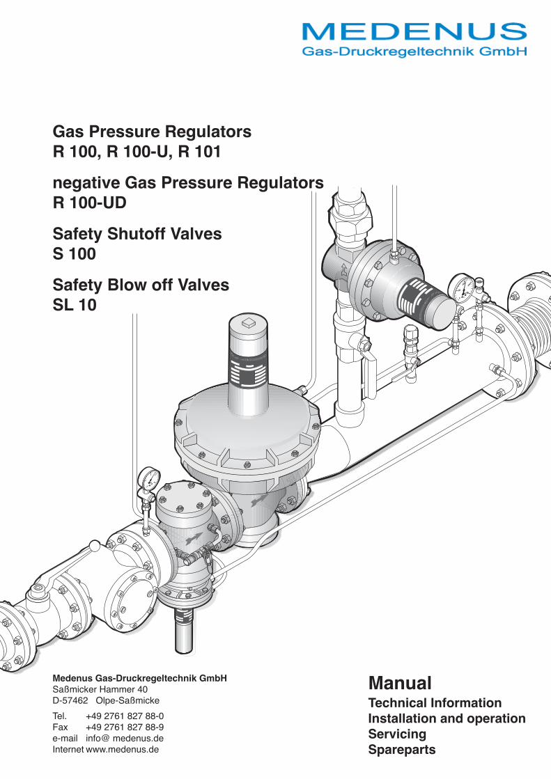
Medenus Gas-Druckregeltechnik GmbHSaßmicker Hammer 40D-57462 Olpe-SaßmickeTel. +49 2761 827 88-0Fax +49 2761 827 88-9e-mail info@ medenus.deInternet www.medenus.de
ManualTechnical InformationInstallation and operationServicingSpareparts
Gas Pressure RegulatorsR 100, R 100-U, R 101negative Gas Pressure RegulatorsR 100-UDSafety Shutoff ValvesS 100Safety Blow off ValvesSL 10
R 101R 100 SL 10
2
S 100
Content1 Important instructions
1.1 Guarantee and liability 31.2 Symbols, instructions 31.3 Abbrevations 3
2 Safety information2.1 Dangers when using the equipment 32.2 Personnel requirements 32.3 local codes of practice 32.4 Hand-over and operating instructions 32.5 Safety in operation 32.6 Actions when gas is smelt 3
3 Technical descriptions3.1 R 100, R 101 Construction and function 43.2 S 100 Construction and function 53.3 SL 10 Construction and function 53.4 Operating conditions 53.5 Product-Specification 53.6 R 100/R 101-Dimensions 63.7 S 100-Dimensions 73.8 SL 10-Dimensions 73.9 Materials 7
4 Installation S 100, R 100/R 101 and SL 104.1 Basic gas train installation 84.2 Installation into the gas train 94.3 Works on the gas train 104.4 Soundness test 10
5 Commissioning and Operation5.1 Gas line filling and venting 105.2 Set regulator/governor 115.3 R-Spring removing and fitting 115.4 Pressure checks 115.5 R-Springs for outlet pressure P2 125.6 SL 10-Safety blow off valve springs 125.7 S 100-High pressure setting 135.8 S 100-Low setting 135.9 SL 10-Setting 135.10 S 100-Springs for MAX.-outlet pressure 145.11 S 100-Springs for MIN.-outlet pressure 145.12 S 100-shutoff and reset 14
6 Faults, cause and rectification 157 Servicing and repairs 158 Replacement of parts
8.1 Repairs 168.2 Order data 168.3 Replacement parts 16
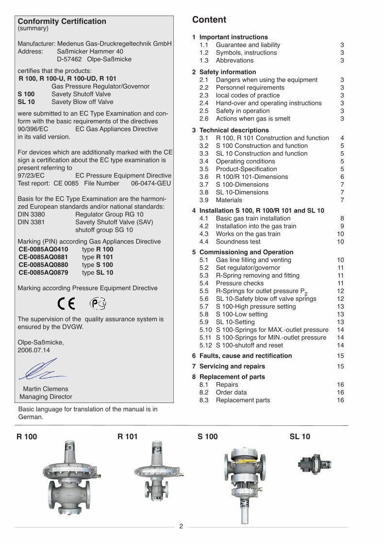
Conformity Certification(summary)
Manufacturer: Medenus Gas-Druckregeltechnik GmbHAddress: Saßmicker Hammer 40
D-57462 Olpe-Saßmickecertifies that the products:R 100, R 100-U, R 100-UD, R 101
Gas Pressure Regulator/GovernorS 100 Savety Shutoff ValveSL 10 Savety Blow off Valvewere submitted to an EC Type Examination and con-form with the basic requirements of the directives90/396/EC EC Gas Appliances Directivein its valid version.
For devices which are additionally marked with the CEsign a certification about the EC type examination ispresent referring to97/23/EC EC Pressure Equipment DirectiveTest report: CE 0085 File Number 06-0474-GEU
Basis for the EC Type Examination are the harmoni-zed European standards and/or national standards:DIN 3380 Regulator Group RG 10DIN 3381 Savety Shutoff Valve (SAV)
shutoff group SG 10Marking (PIN) according Gas Appliances DirectiveCE-0085AQ0410 type R 100CE-0085AQ0881 type R 101CE-0085AQ0880 type S 100CE-0085AQ0879 type SL 10
Marking according Pressure Equipment Directive
The supervision of the quality assurance system isensured by the DVGW.
Olpe-Saßmicke,2006.07.14
Martin ClemensManaging DirectorBasic language for translation of the manual is inGerman.
3
2 Safety informations2.1 Dangers when using the equipment
MEDENUS-products correspond to the relevantexisting standards and guidelines and the recog-nised safety laws.However, improper use of the devices could causedanger for the user or a third party, or result indamage of the device or plant.Therefore the equipment is only to be used• for its intended purpose• under proper conditions• with reference to the information of that installa-
tion and operating instruction as well as theinspection and servicing specifications whichare valid for the effiency and safety of the wholeplant.
Malfunctions or faults must be rectified immedia-tely.
2.2 Personnel requirementsInstallation of the equipment should only be madeby competent personnel.For setting and repairs only qualified persons areauthorized.
2.3 local codes of practiceTo local regulations and codes must be payedattention and observed, concerning• Gas lines, installation of the gas plant• Gas supply• Works on the gas plant• Safety guidelines.
2.4 Hand-over and operating instructionsThe operating instruction shall be passed by thecontractor to the operator of the gas plant prior tohand-over.The operator is to be informed that the manualmust be kept carefully.
2.5 Safety in operationThe equipment is only to be used under correctworking order of all safety devices.At least once a year the equipment should bechecked by an agent of the contractor or qualifiedperson for signs of visible damage and workability.Depending to plant conditions more frequent safetychecks may be required.
2.6 Actions when gas is smelt• Close gas shutoff valve.• Avoid open flame or spark generation by swit-
ching on electric units, lights, mobile phones etc.• Open windows and doors.• Warn all occupants and evacuate the building.• The appropriate gas installer or gas supplier is to
be informed from outside the building.
1 Important instructionsThe manual contains all Informations for authorizedqualified personnel for correct assembly, commissio-ning, setting, servicing, fault finding and repairs.It is an integral part of the equipment and must be keptpermanently on site.The notes and instructions must be followed at workswith the equipment or the gas train.
1.1 Guarantee and liabilityLiability will not be accepted or met any guaran-tee claims for personal injury or damage to pro-perty arising as a result of not paying attention toone or more of the causes below:• Use of the equipment as the intended conditions.• Proper assembly, commissioning, setting,
operation and servicing of the equipment.• Operating the product only with correct installed
and functioning safety and protection devices.• The instructions of assembly and operation of
the equipment resp. the whole plant.• The servicing instructions.• Properly executed repairs.• Use of correct fuel gas.• No obstruction or damage of supply lines.• Use of original MEDENUS spare parts
or• Force majuere.Strictly forbidden• Constructional alterations of the equipment.• Continued use despite the occurrence of a fault.
1.2 Symbols, instructionsIn the manual symbols mark safety instructions toinform which, if not followed, could result:
ATTENTIONDamage of the device, the destructionof the plant or environmental damage.
DANGERSerious injury to health or death.
1.3 AbbrevationsAbbrevations are explained as follows:P
1Gas pressure on inlet of regulator/governor
P2
Gas pressure on outlet of regulator/gover-nor, controlled
V Flow rate (normal volume VN) m3n/hSSV Safety shutoff ValveSBV Safety blow off Valve
3
2
1
4
7
5
8
9
7
8
3
2
1
4
7
5
8
9
7
8
3
2
1
4
7
5
8
9
7
8
3
2
1
4
7
5
6
8
9
3
2
1
4
7
5
8
9
7
8
3
2
1
4
7
5
8
9
7
8
3
2
1
4
7
5
8
9
7
8
3
2
1
4
7
5
6
8
9
4
R 100
R 100-UD
R 101
R 100-U
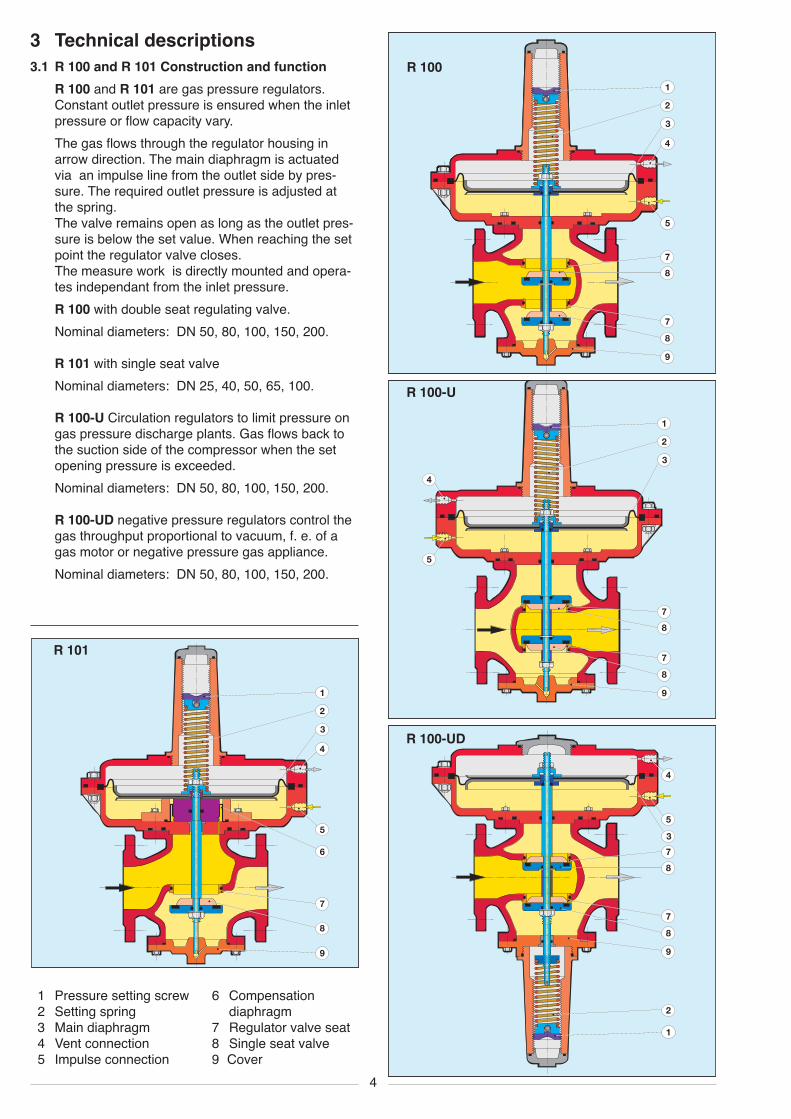
3 Technical descriptions3.1 R 100 and R 101 Construction and function
R 100 and R 101 are gas pressure regulators.Constant outlet pressure is ensured when the inletpressure or flow capacity vary.The gas flows through the regulator housing inarrow direction. The main diaphragm is actuatedvia an impulse line from the outlet side by pres-sure. The required outlet pressure is adjusted atthe spring.The valve remains open as long as the outlet pres-sure is below the set value. When reaching the setpoint the regulator valve closes.The measure work is directly mounted and opera-tes independant from the inlet pressure.R 100 with double seat regulating valve.Nominal diameters: DN 50, 80, 100, 150, 200.
R 101 with single seat valveNominal diameters: DN 25, 40, 50, 65, 100.
R 100-U Circulation regulators to limit pressure ongas pressure discharge plants. Gas flows back tothe suction side of the compressor when the setopening pressure is exceeded.Nominal diameters: DN 50, 80, 100, 150, 200.
R 100-UD negative pressure regulators control thegas throughput proportional to vacuum, f. e. of agas motor or negative pressure gas appliance.Nominal diameters: DN 50, 80, 100, 150, 200.
1 Pressure setting screw2 Setting spring3 Main diaphragm4 Vent connection5 Impulse connection
6 Compensationdiaphragm
7 Regulator valve seat8 Single seat valve9 Cover
8
4 521 6 73
p2
10
11
12
5
4
16
17
18
19
13
14
15
20
21
22
9
8
4 521 6 73
p2
10
11
12
5
4
16
17
18
19
13
14
15
20
21
22
9
5
SL 10
S 100
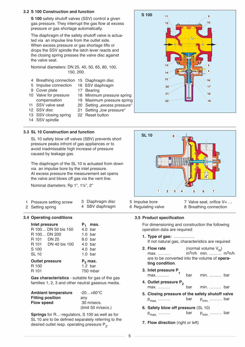
3.3 SL 10 Construction and functionSL 10 safety blow off valves (SBV) prevents shortpressure peaks infront of gas appliances or toavoid inadmissable high increase of pressurecaused by leakage gas.
The diaphragm of the SL 10 is actuated from downvia an impulse bore by the inlet pressure.At excess pressure the measurement set opensthe valve and blows off gas via the vent line.Nominal diameters: Rp 1”, 1½”, 2”
3.2 S 100 Construction and functionS 100 safety shutoff valves (SSV) control a givengas pressure. They interrupt the gas flow at excesspressure or gas shortage automatically.The diaphragm of the safety shutoff valve is actua-ted via an impulse line from the outlet side.When excess pressure or gas shortage lifts ordrops the SSV spindle the latch lever reacts andthe closing spring presses the valve disc againstthe valve seat.Nominal diameters: DN 25, 40, 50, 65, 80, 100,
150, 200.4 Breathing connection5 Impulse connection9 Cover plate
10 Valve for pressurecompensation
11 SSV valve seat12 SSV disc13 SSV closing spring14 SSV spindle
15 Diaphragm disc16 SSV diaphragm17 Bearing18 Minimum pressure spring19 Maximum pressure spring20 Setting „excess pressure“21 Setting „low pressure“22 Reset button
3.4 Operating conditionsInlet pressure P1 max.R 100… DN 50 bis 150 4.0 barR 100… DN 200 1.0 barR 101 DN 25 8.0 barR 101 DN 40 bis 100 4.0 barS 100 4.0 barSL 10 1.0 barOutlet pressure P2 max.R 100 1.2 barR 101 750 mbarGas characteristics - suitable for gas of the gasfamilies 1, 2, 3 and other neutral gaseous media.
Ambient temperature -20…+60°CFitting position anyFlow speed 30 m/secs.
(limit 50 m/secs.)Springs for R…-regulators, S 100 as well as forSL 10 are to be defined separately referring to thedesired outlet resp. operating pressure P2.
3.5 Product specificationFor dimensioning and construction the followingoperation data are required:1. Type of gas: ……………
If not natural gas, characteristics are required2. Flow rate (normal volume VN)
max. ……… m3n/h min. ……… m3n/hare to be converted into the volume of opera-ting condition.
3. Inlet pressure P1max.……… bar min. ……… bar4. Outlet pressure P2max. ……… bar min. ……… bar5. Closing pressure of the safety shutoff valve
pmax. ……… bar pmin. ……… bar
6. Safety blow off pressure (SL 10)pmax. ……… bar pmin. ……… bar
7. Flow direction (right or left)
1 Pressure setting screw2 Setting spring
5 Impulse bore6 Regulating valve
7 Valve seat, orifice V= …8 Breathing connection
3 Diaphragm disc4 SBV diaphragm
6
P1 P2
BA
Ø D
DN
X
L
Rp
3/8
P1 P2
BA
Ø D
DN
X
L
Rp
3/8
P1P2
P1P2
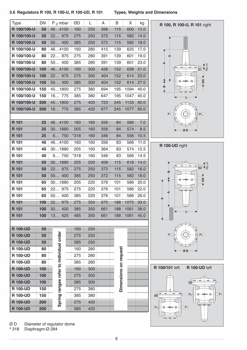
DN P 2 mbar ØD L A B X kgR 100/100-U 50 46…4100 160 250 398 115 600 12.0R 100/100-U 50 22… 975 275 250 372 115 582 14.0R 100/100-U 50 50… 400 385 250 372 115 582 18.0R 100/100-U 80 46…4100 160 280 415 139 625 17.0R 100/100-U 80 22… 975 275 280 391 139 601 19.0R 100/100-U 80 50… 400 385 280 391 139 601 23.0R 100/100-U 100 46…4100 160 300 428 152 638 21.0R 100/100-U 100 22… 975 275 300 404 152 614 23.0R 100/100-U 100 50… 400 385 300 404 152 614 27.0R 100/100-U 150 45…1800 275 380 694 195 1094 40.0R 100/100-U 150 16… 775 385 380 647 195 1047 45.0R 100/100-U 200 45…1800 275 420 723 245 1133 60.0R 100/100-U 200 16… 775 385 420 677 245 1077 65.0
R 101 25 46…4100 160 160 356 84 566 7.0R 101 25 30…1880 205 160 356 84 574 8.5R 101 25 6… 750 *318 160 346 84 556 10.5R 101 40 46…4100 160 160 356 83 566 11.0R 101 40 30…1880 205 160 364 83 574 12.5R 101 40 6… 750 *318 160 346 83 566 14.5R 101 50 30…1880 205 250 408 115 618 14.0R 101 50 22… 975 275 250 372 115 582 16.0R 101 50 50… 400 385 250 372 115 582 18.0R 101 65 30…1880 205 220 376 101 586 20.0R 101 65 22… 975 275 220 376 101 586 22.0R 101 65 50… 400 385 220 376 101 586 26.0R 101 100 22… 975 275 350 675 188 1075 33.0R 101 100 50… 400 385 350 661 188 1061 38.0R 101 100 13… 425 485 350 661 188 1061 45.0
R 100-UD 50 160 250R 100-UD 50 275 250R 100-UD 50 385 250R 100-UD 80 160 280R 100-UD 80 275 280R 100-UD 80 385 280R 100-UD 100 160 300R 100-UD 100 275 300R 100-UD 100 385 300R 100-UD 150 275 380R 100-UD 150 385 380R 100-UD 200 275 420R 100-UD 200 385 420Sp
ringranges
refertoindivid
ualorder
R 100, R 100-U, R 101 right
R 100-UD right
R 100/101 left R 100-UD left
Ø D Diameter of regulator dome* 318 Diaphragm-Ø 284
3.6 Regulators R 100, R 100-U, R 100-UD, R 101 Types, Weights and Dimensions
Type
Dimensio
nson
request
7
L
AB
X
Ø D
DN
Rp
3/8
P1 P1
ØD
BA
L
Rp
X
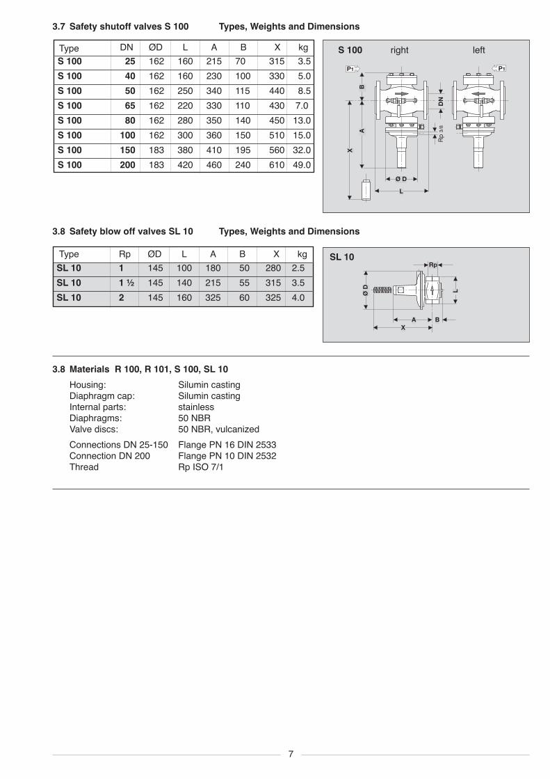
SL 10Rp ØD L A B X kgSL 10 1 145 100 180 50 280 2.5SL 10 1 ½ 145 140 215 55 315 3.5SL 10 2 145 160 325 60 325 4.0
DN ØD L A B X kgS 100 25 162 160 215 70 315 3.5S 100 40 162 160 230 100 330 5.0S 100 50 162 250 340 115 440 8.5S 100 65 162 220 330 110 430 7.0S 100 80 162 280 350 140 450 13.0S 100 100 162 300 360 150 510 15.0S 100 150 183 380 410 195 560 32.0S 100 200 183 420 460 240 610 49.0
S 100 right left
3.8 Safety blow off valves SL 10 Types, Weights and Dimensions
3.8 Materials R 100, R 101, S 100, SL 10Housing: Silumin castingDiaphragm cap: Silumin castingInternal parts: stainlessDiaphragms: 50 NBRValve discs: 50 NBR, vulcanizedConnections DN 25-150 Flange PN 16 DIN 2533Connection DN 200 Flange PN 10 DIN 2532Thread Rp ISO 7/1
3.7 Safety shutoff valves S 100 Types, Weights and Dimensions
Type
Type
100
0
200300
400mb
ar
ß ut uØ”—wasWt ruckregelgerät
1
0
2 3
4bar
1
45
6
12
13
14
20
P1
P2
11
ß ut uØ”—wasWt ruckregelgerät
100
0
200300
400mb
ar
13
14
20
P1
24
12
11
26
25
P0
100
0
200300
400mb
ar100
0
200300
400mb
ar
ßutuØ”—wasWtruckregelgerät
ß ut uØ”—wasWt ruckregelgerät
1
0
2 3
4bar
18
23
1
2
3
45
6
7
8
9
10
1213
14
15
16
17
19
2021
22
P1
P2
11
8
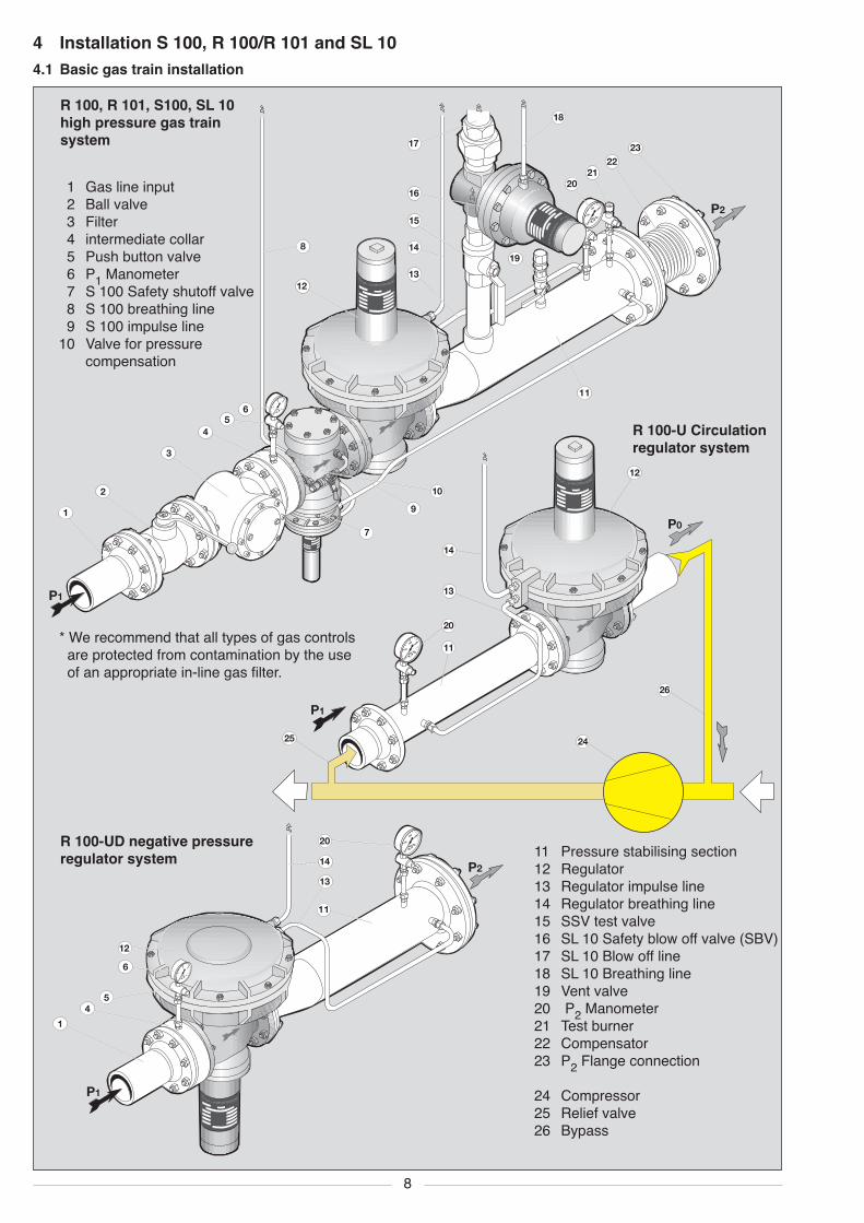
* We recommend that all types of gas controlsare protected from contamination by the useof an appropriate in-line gas filter.
1 Gas line input2 Ball valve3 Filter4 intermediate collar5 Push button valve6 P1 Manometer7 S 100 Safety shutoff valve8 S 100 breathing line9 S 100 impulse line
10 Valve for pressurecompensation
11 Pressure stabilising section12 Regulator13 Regulator impulse line14 Regulator breathing line15 SSV test valve16 SL 10 Safety blow off valve (SBV)17 SL 10 Blow off line18 SL 10 Breathing line19 Vent valve20 P2 Manometer21 Test burner22 Compensator23 P2 Flange connection
24 Compressor25 Relief valve26 Bypass
R 100-U Circulationregulator system
R 100-UD negative pressureregulator system
R 100, R 101, S100, SL 10high pressure gas trainsystem
4 Installation S 100, R 100/R 101 and SL 104.1 Basic gas train installation
ß ut uØ”—wasWt ruckregelgerät
100
0
200300
400mb
ar
13
14
20
P1 ≥ 10 x DN R
X
DN
R
100
0
200300
400mb
ar
ß ut uØ”—wasWt ruckregelgerät
1
0
2 3
4bar
1
45
6
12
13
14
20
P1
P2
11
DN
R
≥ 10 x DN R
≥ 5 x DN P2
DN
P2
X
100
0
200300
400mb
ar
ßutuØ”—wasWtruckregelgerät
ß ut uØ”—wasWt ruckregelgerät
18
P1
P2
8
9
13
14
17
20
DN
R
≥ 10 x DN R
≥ 5 x DN P2
DN
P2X
X
9
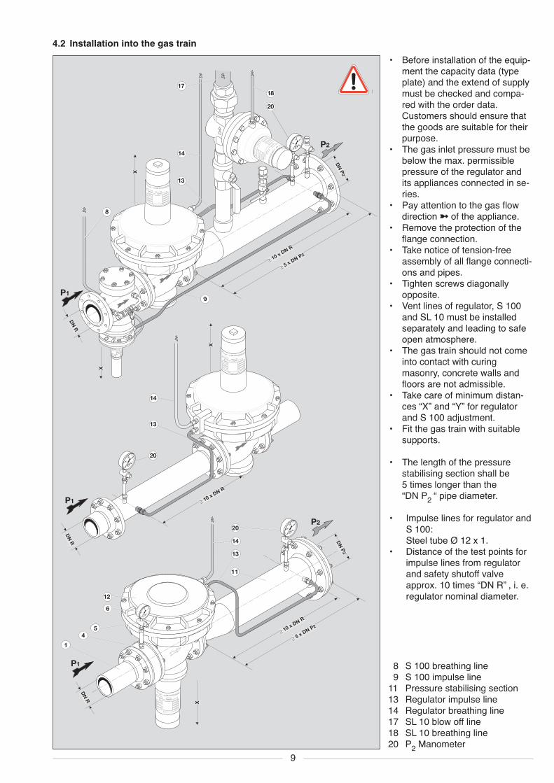
4.2 Installation into the gas train• Before installation of the equip-
ment the capacity data (typeplate) and the extend of supplymust be checked and compa-red with the order data.Customers should ensure thatthe goods are suitable for theirpurpose.
• The gas inlet pressure must bebelow the max. permissiblepressure of the regulator andits appliances connected in se-ries.
• Pay attention to the gas flowdirection � of the appliance.
• Remove the protection of theflange connection.
• Take notice of tension-freeassembly of all flange connecti-ons and pipes.
• Tighten screws diagonallyopposite.
• Vent lines of regulator, S 100and SL 10 must be installedseparately and leading to safeopen atmosphere.
• The gas train should not comeinto contact with curingmasonry, concrete walls andfloors are not admissible.
• Take care of minimum distan-ces “X” and “Y” for regulatorand S 100 adjustment.
• Fit the gas train with suitablesupports.
• The length of the pressurestabilising section shall be5 times longer than the“DN P2 “ pipe diameter.
• Impulse lines for regulator andS 100:Steel tube Ø 12 x 1.
• Distance of the test points forimpulse lines from regulatorand safety shutoff valveapprox. 10 times “DN R” , i. e.regulator nominal diameter.
8 S 100 breathing line9 S 100 impulse line
11 Pressure stabilising section13 Regulator impulse line14 Regulator breathing line17 SL 10 blow off line18 SL 10 breathing line20 P2 Manometer
10
1
0
2 3
4bar1
0
2 3
4bar
1
0
2 3
4bar
2
10
710
10
4.4 Soundness testBefore setting into operation or after service on appli-ances and fittings the complete gas train is to besoundness checked.• Close the ball valve infront the gas train.• Close following shut off devices (solenoid resp.
pneumatic valves).• If the test pressure exceeds the blow off pressure
of the SL 10, close the line infront of the SL 10.• Connect the test assembly to test points infront
and behind the regulating device.• Test with air:
- Test pressure ≥ P2 x 1.5- Waiting time for pressureequalisation 5 minutes
- Test duration 5 minutes- max. permissible pressure loss 1 mbar
• Following the soundness test:Open the ball valve of the SL 10 line.
4.3 Works on the gas train• In principle only well instructed personel is authori-
ced to work on the gas train.• Never work on the appliance under gas pressure
or under electrical power.• Avoid open flames.• Observe local safety regulations.• Only tested and approved sealing material should
be used.Take notice of the user instructions!
• Allways use new seals after removal or exchangeof parts.
• Having finished works on the gas train:Check function and tightness.
Not following these instructions could resultdamages to persons, property or environ-ment.
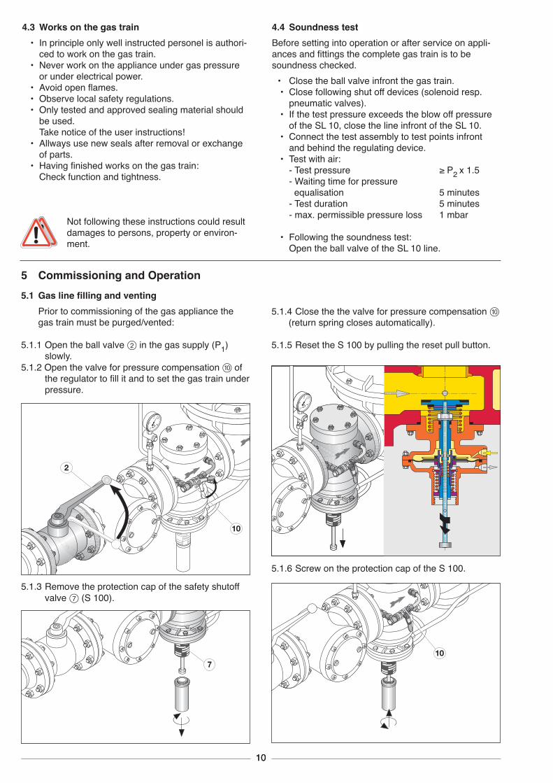
5 Commissioning and Operation
5.1.3 Remove the protection cap of the safety shutoffvalve 7 (S 100).
5.1.4 Close the the valve for pressure compensation 0(return spring closes automatically).
5.1.5 Reset the S 100 by pulling the reset pull button.
5.1.6 Screw on the protection cap of the S 100.
5.1 Gas line filling and ventingPrior to commissioning of the gas appliance thegas train must be purged/vented:
5.1.1 Open the ball valve 2 in the gas supply (P1)slowly.
5.1.2 Open the valve for pressure compensation 0 ofthe regulator to fill it and to set the gas train underpressure.
11
21
100
0
200300
400mb
ar
ßutuØ”—wasWtruckregelgerät
15
19
ß ut uØ”—wasWt ruckregelgerät
ruckregelgerät
ß ut uØ”—wasWt ruckregelgerät
ruckregelgerät
6P11
0
2 3
4bar
20 P2
100
0
200300
400mb
ar
gelgerät
ß ut uØ”—wasWt ruckregelgerät
15
5.3 R-Spring removing and fittingIf the setting of the required outlet pressure is not pos-sible check the range of the spring and change thespring if necessary.5.3.1 Remove the regulator cap,
turn out the setting screw,pull out the setting disc with ball and spring,exchange the spring for a suitable one.
5.1.7 Vent the gas train via hose o to safe atmosphereand check by means of the test burner a.Dont use the test burner for venting!
Air or inert gas should be expelled fully and thegas train filled with gas.
5.1.8 Close Vent valve t and refit cover cap.
5.2.2 Turn the setting screw with a screwdriver:to right pressure increaseto left pressure reduction
5.2.3 Screw on the regulator cap.
5.3.2 Fit setting disc with ball and setting screw.
5.3.3 Adjust the required outlet/flow pressure.
5.3.4 Screw on the regulator cap.
5.4 Pressure checks5.4.1 Measurement of the static pressure when the gas
appliance is switched off6 P1 open the manometer on regulator inlet and
note the pressurep P2 open the manometer on regulator outlet and
note the pressure.
5.4.2 Measurement of the dynamic pressure duringoperation - at Min.- and Max.-Load
6 P1 open the manometer on regulator inlet andnote the pressure
p P2 open the manometer on regulator outlet andnote the pressure.
5.2 Set regulator/governorPrior to commissing use the the test burner to measurethe available pressure and preset the regulator.Set the regulator outlet pressure P2 under maximumgas consumption during operation:5.2.1 Remove the regulator cap.
TT T
12
FA 01 46 52 60 30 36 38 22 23 25 6 7 8 10 11 12 200 40.0 2.5 37FA 02 54 62 72 35 40 44 24 25 27 7 9 10 11 12 13 200 40.0 2.5 25FA 03 60 70 83 40 46 52 26 28 32 9 11 13 12 13 15 205 40.0 2.5 17.3FA 04 70 90 108 45 55 64 30 33 38 11 14 17 13 15 17 205 40.0 2.5 12.2FA 05 90 120 150 50 62 76 34 40 47 14 19 24 15 19 21 205 40.0 3.5 26.3FA 06 120 164 208 60 80 103 40 50 60 20 28 36 19 23 27 205 40.0 3.5 18.1FA 07 160 220 290 76 108 140 52 67 82 27 38 50 23 29 35 205 40.0 3.5 12.6FA 08 225 325 415 110 156 206 70 90 115 39 58 78 30 40 50 205 40.0 4.0 13.6FA 09 325 473 620 147 222 302 90 123 160 55 82 110 36 50 65 205 40.0 5.0 19.5FA 10 472 695 922 205 320 425 130 183 238 82 123 165 54 75 100 205 40.0 5.3 16.3FA 11 700 1040 1385 300 450 634 185 265 345 123 187 255 80 110 145 205 40.0 6.0 16.4FA 12 980 1489 2020 390 645 900 253 373 490 167 267 365 105 155 205 200 40.0 6.5 15.2FA 13 1670 2435 3250 700 1070 1462 400 580 760 300 450 590 170 243 325 205 40.0 7.0 12.8FA 14 1650 2800 4100 670 1250 1880 405 680 975 300 520 750 175 290 400 190 40.0 7.5 11.2
Min. Max. L0 Øm øs Zmbar mbar mm mm mm
F100 B 20 50 90 31 2.0 11/13F100 B 25 80 90 32 2.5 12/14F101 40 150 90 33 3.0 12/14F102 60 330 90 34 3.5 11/13F104 110 600 90 34 4.0 5.5/7F105 450 1050 90 34 4.0 7/9F106 700 1800 90 36 5.0 8/10
Øm
L0
sø
F 70 45 50 16 25 13 15 400 62.5 3.5 13F 71 50 80 20 30 15 20 400 62.5 4.0 13F 711 80 110 30 44 20 28 400 64.0 5.0 15F 72 110 160 44 68 28 42 400 64.0 6.0 16F 73 140 240 58 90 36 54 400 64.0 6.0 12F 73A 200 300 71 120 43 65 400 64.5 6.5 13F 74 260 340 98 140 52 81 400 64.0 7.0 13F 74A 300 400 111 178 65 101 400 64.0 7.5 13F 742 400 500 138 223 79 126 400 64.0 8.0 13F 742A 480 580 170 275 97 154 400 64.0 8.5 13F 743 560 760 206 337 117 188 400 64.0 9.0 13F 743A 700 900 270 443 151 245 400 63.0 9.5 13F 78* 880 1400 369 608 205 335 400 59.5 10.5 15F 76A* 1150 1800 469 775 260 425 400 58.0 11.0 15
5.5 Regulator springs for outlet pressure P2 -setting, spring data
� x = number of right turns to increase the pressure up to … mbar
R 100 - DN 50/80/100, R 101 - DN 25/40/50/65 Diaphragm Diameter T = 16 - 39 - 62 mm *D 160 Ø D 205 Ø D 275 Ø D 318 Ø D 385 Ø Spring Data
� x 10 20 30 10 20 30 10 20 30 10 20 30 10 20 30 L0 Øm øs ZSpring mbar mbar mbar mbar mbar mm mm mm
T * Screw-in depth in mm
* FA 12, FA 13, FA 14, F 78, F 76Awith high pressure screw spindle
R 100 - DN 150/200, R 101 - DN 80/100 T = 80-130 mm *Diaphragm Diameter Spring Data
Spring D 275 Ø D 385 Ø D 485 Ø L0 Øm øs ZNo. mbar mbar mbar mm mm mm
5.6 SL 10 Safety blow off valve springsSpringNo.
F 104 HD-design (high pressure) from 400 mbarF 105 and F 106 HD-design for high pressure
R 100-U, R 100-UD Springs on request.
L0 Length of springØm Spring inside diameterøs Spring wire diameterZ Number of spring windings
18
19
20
21
18
19
20
21
13
100
0
200300
400mb
ar
MEDENUSG
as-Druckreg
elgerä
t
15
16
100
0
200300
400mb
ar
MEDENUSG
as-Druckreg
elgerä
t
15
16
17
uØ”—wasWtruckregelgerät
15
16
—wasWtruckregelgerät
15
16
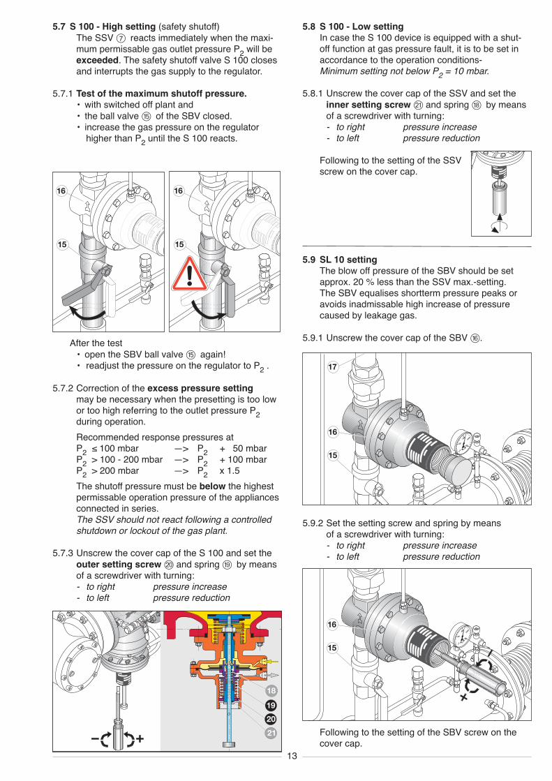
5.7 S 100 - High setting (safety shutoff)The SSV 7 reacts immediately when the maxi-mum permissable gas outlet pressure P2 will beexceeded. The safety shutoff valve S 100 closesand interrupts the gas supply to the regulator.
5.7.1 Test of the maximum shutoff pressure.• with switched off plant and• the ball valve t of the SBV closed.• increase the gas pressure on the regulator
higher than P2 until the S 100 reacts.
5.9 SL 10 settingThe blow off pressure of the SBV should be setapprox. 20 % less than the SSV max.-setting.The SBV equalises shortterm pressure peaks oravoids inadmissable high increase of pressurecaused by leakage gas.
5.9.1 Unscrew the cover cap of the SBV z.
5.9.2 Set the setting screw and spring by meansof a screwdriver with turning:- to right pressure increase- to left pressure reduction
5.8 S 100 - Low settingIn case the S 100 device is equipped with a shut-off function at gas pressure fault, it is to be set inaccordance to the operation conditions-Minimum setting not below P2 = 10 mbar.
5.8.1 Unscrew the cover cap of the SSV and set theinner setting screwa and spring i by meansof a screwdriver with turning:- to right pressure increase- to left pressure reduction
Following to the setting of the SSVscrew on the cover cap.
5.7.2 Correction of the excess pressure settingmay be necessary when the presetting is too lowor too high referring to the outlet pressure P2during operation.Recommended response pressures atP2 ≤ 100 mbar —> P2 + 50 mbarP2 > 100 - 200 mbar —> P2 + 100 mbarP2 > 200 mbar —> P2 x 1.5The shutoff pressure must be below the highestpermissable operation pressure of the appliancesconnected in series.The SSV should not react following a controlledshutdown or lockout of the gas plant.
5.7.3 Unscrew the cover cap of the S 100 and set theouter setting screwp and spring o by meansof a screwdriver with turning:- to right pressure increase- to left pressure reduction
After the test• open the SBV ball valve t again!• readjust the pressure on the regulator to P2 .
Following to the setting of the SBV screw on thecover cap.
TT
14
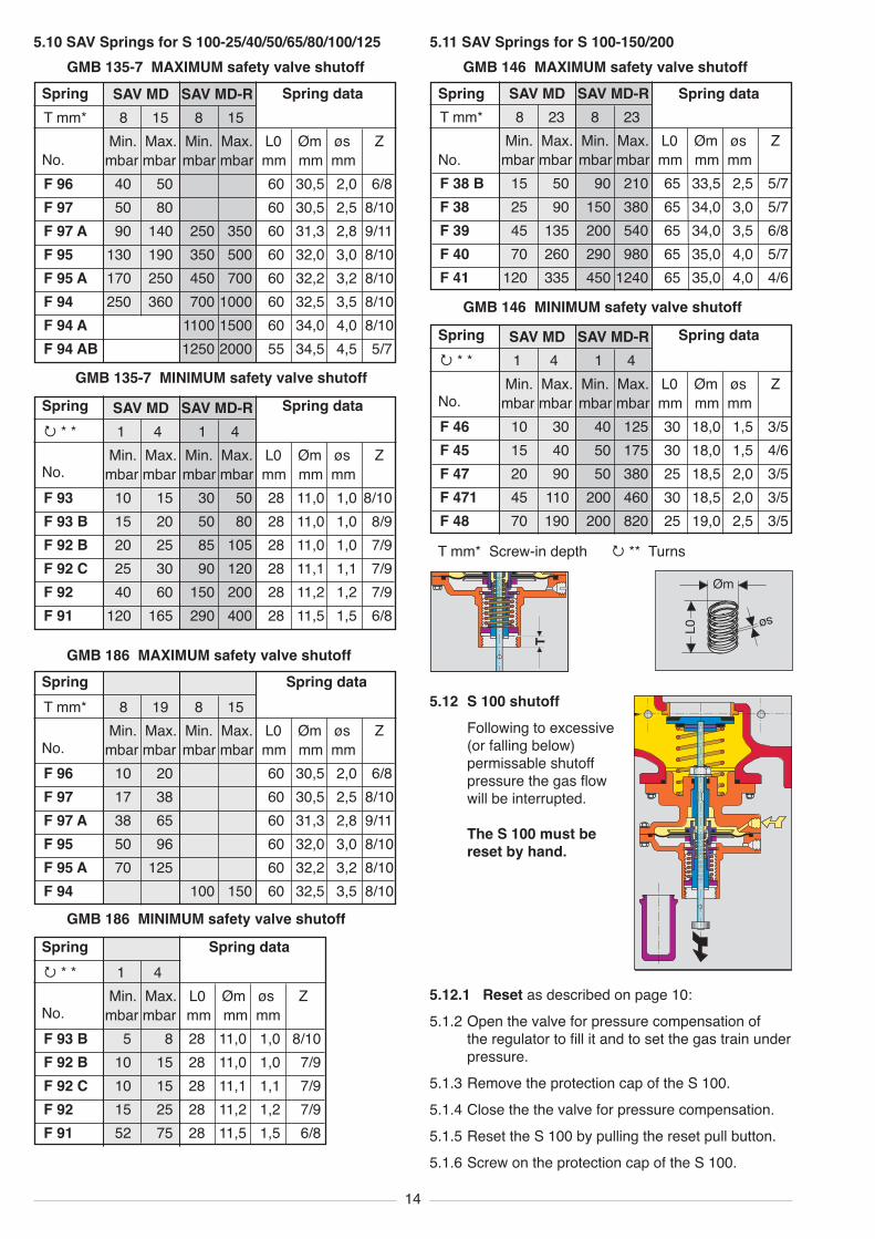
SAV MD SAV MD-RT mm* 8 15 8 15
Min. Max. Min. Max. L0 Øm øs Zmbar mbar mbar mbar mm mm mm
F 96 40 50 60 30,5 2,0 6/8F 97 50 80 60 30,5 2,5 8/10F 97 A 90 140 250 350 60 31,3 2,8 9/11F 95 130 190 350 500 60 32,0 3,0 8/10F 95 A 170 250 450 700 60 32,2 3,2 8/10F 94 250 360 700 1000 60 32,5 3,5 8/10F 94 A 1100 1500 60 34,0 4,0 8/10F 94 AB 1250 2000 55 34,5 4,5 5/7
SAV MD SAV MD-R� * * 1 4 1 4
Min. Max. Min. Max. L0 Øm øs Zmbar mbar mbar mbar mm mm mm
F 93 10 15 30 50 28 11,0 1,0 8/10F 93 B 15 20 50 80 28 11,0 1,0 8/9F 92 B 20 25 85 105 28 11,0 1,0 7/9F 92 C 25 30 90 120 28 11,1 1,1 7/9F 92 40 60 150 200 28 11,2 1,2 7/9F 91 120 165 290 400 28 11,5 1,5 6/8
T mm* 8 19 8 15Min. Max. Min. Max. L0 Øm øs Zmbar mbar mbar mbar mm mm mm
F 96 10 20 60 30,5 2,0 6/8F 97 17 38 60 30,5 2,5 8/10F 97 A 38 65 60 31,3 2,8 9/11F 95 50 96 60 32,0 3,0 8/10F 95 A 70 125 60 32,2 3,2 8/10F 94 100 150 60 32,5 3,5 8/10
� * * 1 4Min. Max. L0 Øm øs Z
mbar mbar mm mm mmF 93 B 5 8 28 11,0 1,0 8/10F 92 B 10 15 28 11,0 1,0 7/9F 92 C 10 15 28 11,1 1,1 7/9F 92 15 25 28 11,2 1,2 7/9F 91 52 75 28 11,5 1,5 6/8
SAV MD SAV MD-RT mm* 8 23 8 23
Min. Max. Min. Max. L0 Øm øs Zmbar mbar mbar mbar mm mm mm
F 38 B 15 50 90 210 65 33,5 2,5 5/7F 38 25 90 150 380 65 34,0 3,0 5/7F 39 45 135 200 540 65 34,0 3,5 6/8F 40 70 260 290 980 65 35,0 4,0 5/7F 41 120 335 450 1240 65 35,0 4,0 4/6
SAV MD SAV MD-R� * * 1 4 1 4
Min. Max. Min. Max. L0 Øm øs Zmbar mbar mbar mbar mm mm mm
F 46 10 30 40 125 30 18,0 1,5 3/5F 45 15 40 50 175 30 18,0 1,5 4/6F 47 20 90 50 380 25 18,5 2,0 3/5F 471 45 110 200 460 30 18,5 2,0 3/5F 48 70 190 200 820 25 19,0 2,5 3/5
Øm
L0
sø
T mm* Screw-in depth � ** Turns
5.12 S 100 shutoffFollowing to excessive(or falling below)permissable shutoffpressure the gas flowwill be interrupted.
The S 100 must bereset by hand.
5.11 SAV Springs for S 100-150/200GMB 146 MAXIMUM safety valve shutoff
Spring Spring data
No.
GMB 146 MINIMUM safety valve shutoffSpring Spring data
No.
5.10 SAV Springs for S 100-25/40/50/65/80/100/125GMB 135-7 MAXIMUM safety valve shutoff
Spring Spring data
No.
GMB 135-7 MINIMUM safety valve shutoffSpring Spring data
No.
GMB 186 MAXIMUM safety valve shutoffSpring Spring data
No.
GMB 186 MINIMUM safety valve shutoffSpring Spring data
No.5.12.1 Reset as described on page 10:5.1.2 Open the valve for pressure compensation of
the regulator to fill it and to set the gas train underpressure.
5.1.3 Remove the protection cap of the S 100.5.1.4 Close the the valve for pressure compensation.5.1.5 Reset the S 100 by pulling the reset pull button.5.1.6 Screw on the protection cap of the S 100.
15
6 Faults Cause and rectificationʘ Extreme P2 pressure drop when max. flow rate,
full load capacity cannot be reached, P1 is constantʘ Extreme P2 pressure drop when max. flow rate,
supply pressure P1 drops down
ʘ Heavy P2 variations of pressure (pulsation)
ʘ Loud gas flow noiseʘ Regulator does not work, blocks (does not open)ʘ Regulator blows off during operation
ʘ Noise of regulator
ʘ S 100 shuts off often
Spring or size of regulator not correct. Check dimensi-ons of spring and regulator, possibly exchange.Gas supply pressure is not sufficiant. Increase supplypressure. Pipe cross section too small (too much pres-sure loss in gas supply), checkSetting of gas consumption appliance, check range ofspring possibly size of regulator, impulse line.Speed of gas too high, check size of regulator.Leakage of the compensation diaphragm, exchange.Main diaphragm, screwing in the regulator leakageex-change.Mechanical wear of the regulator spindle, exchange ofthe measure work.Setting of S 100 too low resp. SL 10 too high, correc-tion.
7 Servicing and repairsThe servicing specifications of the installer ofthe plant as well as the safety guidelinesgiven on page 2 of the manual should beobserved.
R regulators, S 100 SSV and SL 10 SBV need noservice except wear parts.Diaphrams are to be checked for their condition.The side of the textile must be placed on theopposite side to the pressure side. The measurework may not be wrenched to avoid any diagonalwrinkle.Valve discs are to be checked for dirt and damage.When installing the regulator valve disc the spindleis to be secured from torsion.
In principle should be observed:• Exchange of faulty components only with
original MEDENUS parts.• Seal joints on flange connections or screwings
which were opened for service works, are to becleaned prior to re-installation.Take care of correct connections.
• Replace damaged seals.• Test tightness following service works and• Check function and setting values!
1
4
5
6
7
4
5
6
7
2
1
2
9
10
8
11
13
12
3
9
8
8
1
3
4
5
3
45
2
1
2
67
6
7
13
12
9
8
13
12
14
17
17
15
16
1822
20
21
23
19
16
R 100 R 101
SL 10S 100
R 100-U R 101-UD
8 Replacement of parts8.1 Repairs
For replacement only persons fitted with thespecial qualification are authorized.
Pos. Description1 R main diaphragm2 O-ring R-13 O-ring R-24 O-ring R-35 O-ring R-46 R valve disc7 O-ring R-58 O-ring R-69 O-ring R-70 R101 Compensation
diaphragmq R101 O-ring R-8w O-Ring R-9é O-Ring R-10w S100 diaphragmt S100 valve discz O-Ring-S100-1u O-Ring-S100-2i O-Ring-S100-3o SL10 diaphragmp SL10 O-ring 1a SL10 valve discs SL10 O-ring 2d SL10 O-ring 3
Complete setsincl. O-rings:R100 repair kitR100-U repair kitR100-UD repair kitR101 repair kitS100 repair kitSL10 repair kit
8.3 Replacement parts
MEDENUS pressure regulators R100/101, S100, SL10 Edition 11.2007 Print no.: R100-manual.e-G+TRights of modification reserved. All rights reserved.
8.2 Order data for replacement partsrequired data -refferring to type plate-
• Replacement part Description (Pos. No.)• SSV/Regulator-/SBV-Type S100/R100/R101/SL10• Nominal Diameter DN• Production-No. No. …• Year of construction ………• Inlet pressure P1 bar• Outlet pressure P2 mbar• Type of gas ………