Embed Size (px)
Citation preview
Manual Provided by eMilitary Manuals-http://www.emilitarymanuals.com

Manual Provided by eMilitary Manuals-http://www.emilitarymanuals.com
WAR DEPARTMENT TECHNICAL MANUAL
United States Government Printing
January : 1947
WAR DEPARTMENT • JANUARY 1947
CARBINES, CAL. .30,
Ml, M1A1, M2, and M3
TM 9 - 1276
This manual supersedes TM 9-1276, Ordnance Maintenance, Carbines, Cal. .80, Ml and M1A1, 5 June 1943; TB 9-1276-1,15 January 1945; TB ORD 9, 10 January
1944; and TB 23-7-4, 13 October 1944.
Manual Provided by eMilitary Manuals-http://www.emilitarymanuals.com
WAR DEPARTMENT Washington 25, D. C, 22 January 1947
ii
TM 9-1276, Carbines, Cal. .30, Ml , M1A1, M2, and M3, is published for the information and guidance of all concerned.
The material in this manual is correct as of 16 October 1946.
[AG 300.5 (15 Feb 45)].
BY ORDER OF THE SECRETARY OF WAR:
OFFICIAL:
EDWARD F. WITSELL Major General The Adjutant General
DWIGHT D. EISENHOWER, Chief of Staff
D I S T R I B U T I O N :
For explanation of distribution formula, see FM 21-6.
AAF (5); AGF (2); T (10); Dept (5); AAF Maj Comds (2); Arm & Sv Bd (1); Tech Sv (2); FC (1); BU (1) PE, Ord 0 (5); Dist 9 (3); Establishments 9 (3) except Am Establishments (0); Gen & Sp Sv Sch (5); A (ZI) (10), (Oversea) (3); CHQ (2); D (2); AF (3); One (1) copy to each of the following T/O & E's: 9-7; 9-8; 9-9; 9-12; 9-57; 9-65; 9-67; 9-76; 9-315; 9-318; 9-319; 9-377; 9-417.

Manual Provided by eMilitary Manuals-http://www.emilitarymanuals.com
Section I. INTRODUCTION 1-7 1
CONTENTS
Paragraphs Page
APPENDIX 104
iii
II. INSPECTION PRIOR TO DISASSEMBLY 8-17 10
III. TOOLS, GAUGES, AND FIXTURES 18-19 20
IV. GENERAL MAINTENANCE 20-29 27
V. TRIGGER HOUSING GROUP 30-34 42
VI. OPERATING SLIDE ASSEMBLY 35-37 52
VII. BOLT GROUP 38-41 55
VIII. FRONT SIGHT ASSEMBLY 42-45 58
IX. REAR SIGHT ASSEMBLY 46-49 61
X. BARREL AND RECEIVER GROUP 50-53 70
XI. STOCK GROUP 54-57 83
XII. MAGAZINE ASSEMBLY 58-60 95
XIII. EQUIPMENT 61-64 99
XIV. FUNCTION FIRING AND FINAL INSPECTION 65-67 101

Manual Provided by eMilitary Manuals-http://www.emilitarymanuals.com

Manual Provided by eMilitary Manuals-http://www.emilitarymanuals.com
This manual supersedes TM 9—1276, Ordnance Maintenance, Carbines, Cal. .30, Ml and M1A1, 5 June 1943; TB 9-1276-1, 15 January 1945; TB ORD 9, 10 January 1944; and TB 23-7-4, 13 October 1944.
SECTION I
INTRODUCTION
1. Scope
This manual is published for the information and guidance of ordnance maintenance personnel. It contains detailed instructions for inspection, disassembly, assembly, maintenance, and repair of the carbines, cal. .30, M l , M1A1, M2 and M3. This manual does not contain general assembly or disassembly or information which is intended primarily for the using arms. For such information see FM 23-7.
2. Characteristics
The carbines, cal. .30, Ml and M1A1 are gas-operated self-loading, air-cooled shoulder weapons delivering semiautomatic fire and are fed by a 15-round box-type magazine. The carbines, cal. .30, M2 and M3 deliver either semiautomatic or full automatic fire controlled by the operator through the use of a selector and are fed by a 30-round box type magazine. The 15-round and 30-round magazines can be used interchangeably among the various models.
3. Difference Between Models
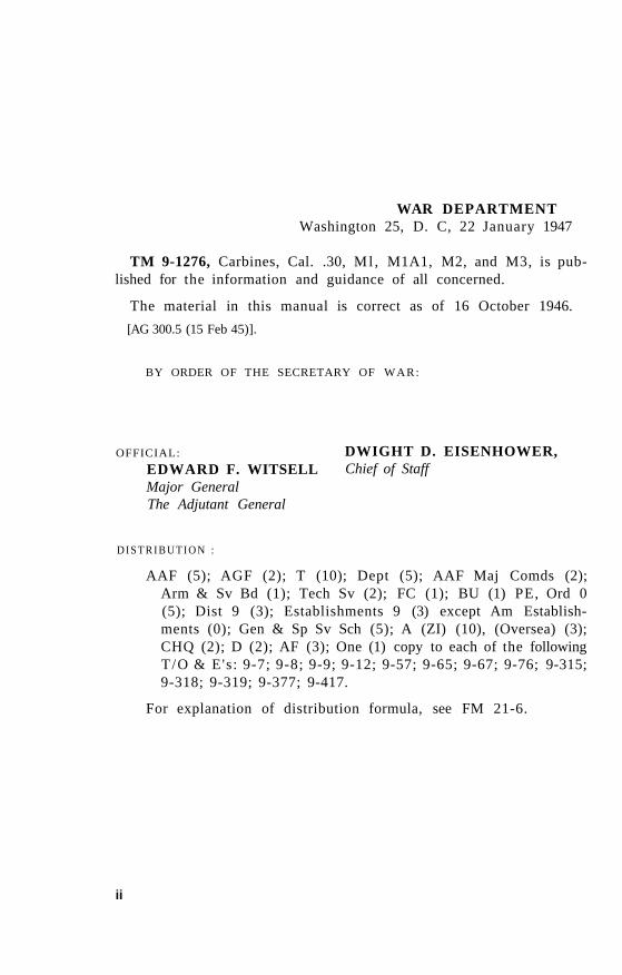
a. CARBINE CAL. .30, M l (fig. 1). This model is the basic carbine. It has a one-piece wooden stock and a hand guard. One end of a sling is attached to a swivel fastened to the front band which retains the stock and hand guard; the other end is looped around an oiler, which is inserted into the right side of the rear end of the stock. The front sight is of the blade type fastened to the muzzle end of the barrel. The rear sight is the adjustable type, either D73955 (machined type) or D7160060 (stamped type). The two sights differ only in method of manufacture.
1
Manual Provided by eMilitary Manuals-http://www.emilitarymanuals.com
Figure 1. Carbine, cal. .30 Ml.
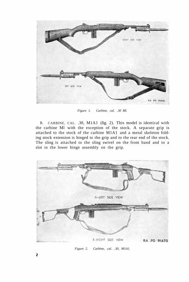
b. CARBINE, CAL. .30, M1A1 (fig. 2). This model is identical with the carbine Ml with the exception of the stock. A separate grip is attached to the stock of the carbine M1A1 and a metal skeleton folding stock extension is hinged to the grip and to the rear end of the stock. The sling is attached to the sling swivel on the front band and to a slot in the lower hinge assembly on the grip.
Figure 2. Carbine, cal. .30, M1A1.
2
Manual Provided by eMilitary Manuals-http://www.emilitarymanuals.com
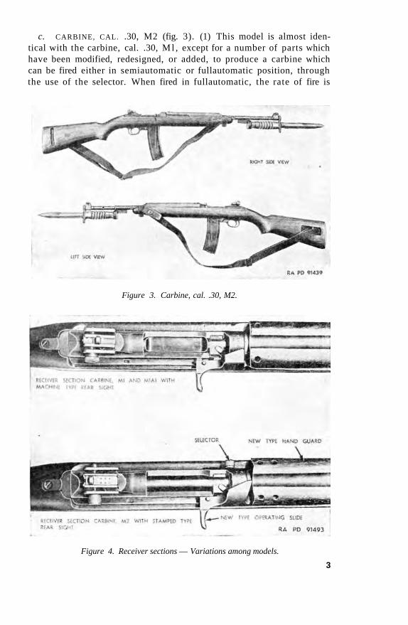
c. CARBINE, CAL. .30, M2 (fig. 3). (1) This model is almost identical with the carbine, cal. .30, M l , except for a number of parts which have been modified, redesigned, or added, to produce a carbine which can be fired either in semiautomatic or fullautomatic position, through the use of the selector. When fired in fullautomatic, the rate of fire is
Figure 3. Carbine, cal. .30, M2.
Figure 4. Receiver sections — Variations among models.
3
Manual Provided by eMilitary Manuals-http://www.emilitarymanuals.com
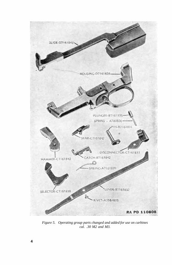
Figure 5. Operating group parts changed and added for use on carbines cal. .30 M2 and M3.
4
Manual Provided by eMilitary Manuals-http://www.emilitarymanuals.com
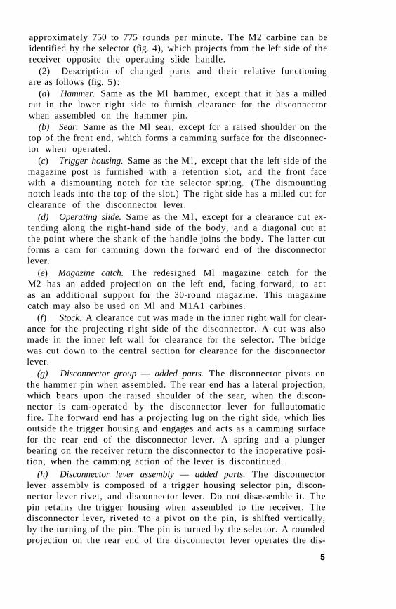
approximately 750 to 775 rounds per minute. The M2 carbine can be identified by the selector (fig. 4), which projects from the left side of the receiver opposite the operating slide handle.
(2) Description of changed parts and their relative functioning are as follows (fig. 5):
(a) Hammer. Same as the Ml hammer, except that it has a milled cut in the lower right side to furnish clearance for the disconnector when assembled on the hammer pin.
(b) Sear. Same as the Ml sear, except for a raised shoulder on the top of the front end, which forms a camming surface for the disconnector when operated.
(c) Trigger housing. Same as the M l , except that the left side of the magazine post is furnished with a retention slot, and the front face with a dismounting notch for the selector spring. (The dismounting notch leads into the top of the slot.) The right side has a milled cut for clearance of the disconnector lever.
(d) Operating slide. Same as the M l , except for a clearance cut extending along the right-hand side of the body, and a diagonal cut at the point where the shank of the handle joins the body. The latter cut forms a cam for camming down the forward end of the disconnector lever.
(e) Magazine catch. The redesigned Ml magazine catch for the M2 has an added projection on the left end, facing forward, to act as an additional support for the 30-round magazine. This magazine catch may also be used on Ml and M1A1 carbines.
(f) Stock. A clearance cut was made in the inner right wall for clearance for the projecting right side of the disconnector. A cut was also made in the inner left wall for clearance for the selector. The bridge was cut down to the central section for clearance for the disconnector lever.
(g) Disconnector group — added parts. The disconnector pivots on the hammer pin when assembled. The rear end has a lateral projection, which bears upon the raised shoulder of the sear, when the disconnector is cam-operated by the disconnector lever for fullautomatic fire. The forward end has a projecting lug on the right side, which lies outside the trigger housing and engages and acts as a camming surface for the rear end of the disconnector lever. A spring and a plunger bearing on the receiver return the disconnector to the inoperative position, when the camming action of the lever is discontinued.
(h) Disconnector lever assembly — added parts. The disconnector lever assembly is composed of a trigger housing selector pin, disconnector lever rivet, and disconnector lever. Do not disassemble it. The pin retains the trigger housing when assembled to the receiver. The disconnector lever, riveted to a pivot on the pin, is shifted vertically, by the turning of the pin. The pin is turned by the selector. A rounded projection on the rear end of the disconnector lever operates the dis-
5
Manual Provided by eMilitary Manuals-http://www.emilitarymanuals.com
connector. A projecting toe the front end of the disconnector lever contacts the camming surface on the operating slide. An offset in the rear section provides for alignment with the slot in the disconnector.
(i) Selector group — added part. The selector is mounted to the left end of the crank pin by means of a slot in the lower forward face of the selector mating with straddle slots in the end of the pin. The selector holds the pin in position and acts as a lever for turning, throwing the disconnector lever into or out of engagement with the operating slide. A curved wire spring holds the selector in position on the pin, and in the fullautomatic or semiautomatic position when operated. The straight front end of the spring seats into a recess in the lower rear end of the selector, and the circular rear end of the spring seats in a vertical slot in the front face of the magazine post on the left side. When assembled, the bow of the spring faces upward.
d. CARBINE, CAL. .30, M3. This model is identical with the carbine, cal. .30, M2 except that the top of the receiver is designed to accommodate special sighting equipment (sniperscope) issued by the Corps of Engineers. Information on the Sniperscope may be found in TM 5-9341. There are no provisions made in this receiver for the conventional rear sight.
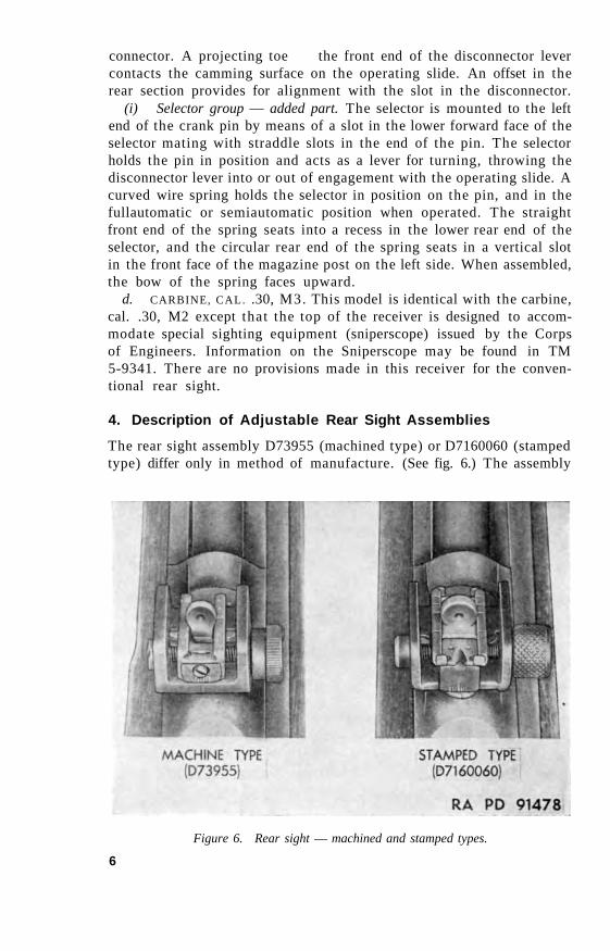
4. Description of Adjustable Rear Sight Assemblies
The rear sight assembly D73955 (machined type) or D7160060 (stamped type) differ only in method of manufacture. (See fig. 6.) The assembly
Figure 6. Rear sight — machined and stamped types.
6
Manual Provided by eMilitary Manuals-http://www.emilitarymanuals.com
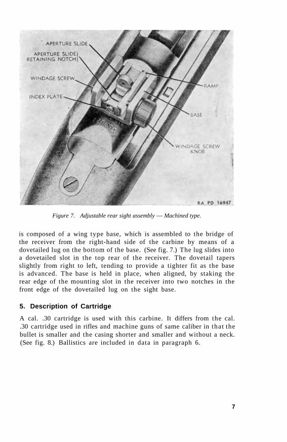
Figure 7. Adjustable rear sight assembly — Machined type.
is composed of a wing type base, which is assembled to the bridge of the receiver from the right-hand side of the carbine by means of a dovetailed lug on the bottom of the base. (See fig. 7.) The lug slides into a dovetailed slot in the top rear of the receiver. The dovetail tapers slightly from right to left, tending to provide a tighter fit as the base is advanced. The base is held in place, when aligned, by staking the rear edge of the mounting slot in the receiver into two notches in the front edge of the dovetailed lug on the sight base.
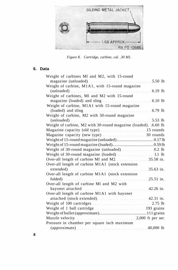
5. Description of Cartridge
A cal. .30 cartridge is used with this carbine. It differs from the cal. .30 cartridge used in rifles and machine guns of same caliber in that the bullet is smaller and the casing shorter and smaller and without a neck. (See fig. 8.) Ballistics are included in data in paragraph 6.
7
Manual Provided by eMilitary Manuals-http://www.emilitarymanuals.com
Figure 8. Cartridge, carbine, cal. .30 M1.
6. Data
Weight of carbines Ml and M2, with 15-round magazine (unloaded) 5.50 lb
Weight of carbine, M1A1, with 15-round magazine (unloaded) 6.19 lb
Weight of carbines, Ml and M2 with 15-round magazine (loaded) and sling 6.10 lb
Weight of carbine, M1A1 with 15-round magazine (loaded) and sling 6.79 lb
Weight of carbine, M2 with 30-round magazine (unloaded) 5.53 lb
Weight of carbine, M2 with 30-round magazine (loaded). .6.60 lb Magazine capacity (old type) 15 rounds Magazine capacity (new type) 30 rounds Weight of 15-round magazine (unloaded).................................. 0.17 lb Weight of 15-round magazine (loaded)..................................... 0.59 lb Weight of 30-round magazine (unloaded) 0.2 lb Weight of 30-round magazine (loaded) 1.1 lb Over-all length of carbine Ml and M2 35.58 in. Over-all length of carbine M1A1 (stock extension
extended) 35.63 in. Over-all length of carbine M1A1 (stock extension
folded) 25.51 in. Over-all length of carbine Ml and M2 with
bayonet attached 42.26 in. Over-all length of carbine M1A1 with bayonet
attached (stock extended) 42.31 in. Weight of 100 cartridges 2.75 lb Weight of 1 ball cartridge 193 grains Weight of bullet (approximate)...........................................111 grains Muzzle velocity 2,000 ft per sec Pressure in chamber per square inch maximum
(approximate) 40,000 lb
8

Manual Provided by eMilitary Manuals-http://www.emilitarymanuals.com
Maximum range......... 2,000 yd Effective range 300 yd Rate of fire, fullautomatic (M2) 750-775 rounds per min Length of barrel 18.00 in. Rifling:
Length 16.77 in. Number of grooves 4 Twist (direction) right hand Twist ...1 turn in 20.00 in. Sight radius at 100 yards 21.5 in. Trigger pull 5-7 lb Shipping weight of arms chest containing 10
carbines Ml and M2 83.00 lb Shipping weight of arms chest containing 10
carbines M1A1 91.00 lb Dimensions of arms chest (outside)...393/8x 103/4 x 103/4 in.
Cubical displacement of arms chest 4.00 cu ft Ballistics of cartridge (FM 23-7)
Note. 7,000 grains equal 1 pound avoirdupois measure.
7. Forms and Records
Ordnance inspection records provide a written record of the status as regards serviceability of ordnance materiel in the hands of troops. These records must be maintained at all times.
9

Manual Provided by eMilitary Manuals-http://www.emilitarymanuals.com
SECTION II
INSPECTION PRIOR TO DISASSEMBLY
8. General
This section covers specific instructions for inspection by ordnance personnel of the materiel in the hands of troops, as well as inspection of the materiel undergoing repair in ordnance shops. The inspector should be well versed in maintenance procedure for the materiel and must have a working knowledge of the tools needed for its inspection.
9. Purpose
a. Fundamentally, inspection is made for the purpose of determining whether materiel is serviceable and dependable, and the extent of its serviceability. Serviceability, as interpreted in this section, is the ability of the carbine to perform completely its intended functions.
b. If the carbine is found unserviceable, determine the cause and extent of unserviceability. If practical, correct on the spot deficiencies in weapons in the hands of troops. If the carbine is being overhauled by an ordnance shop, inspect thoroughly and completely, put into the best possible condition that time, materials, and tactical circumstances will allow, and return to the using arm ready for use. (See serviceability chart, fig. 19.)
10. Reports
a. Forward suggested improvements in design, maintenance, safety and efficiency of operation prompted by chronic failure or malfunction of the weapon, spare parts, accessories or equipment, to the office of the Chief of Ordnance, Field Service, Maintenance Division, Washington 25, D. C, with all available pertinent information necessary to initiate corrective action. Report this information on WD AGO Form 468. (Unsatisfactory Equipment Report). If WD AGO Form 468 is not available, refer to TM 37-250 for list of data required on Unsatisfactory Equipment Report.
b. Report to the responsible officer any pertinent carelessness or negligence in the observance of preventive maintenance procedures
10
Manual Provided by eMilitary Manuals-http://www.emilitarymanuals.com
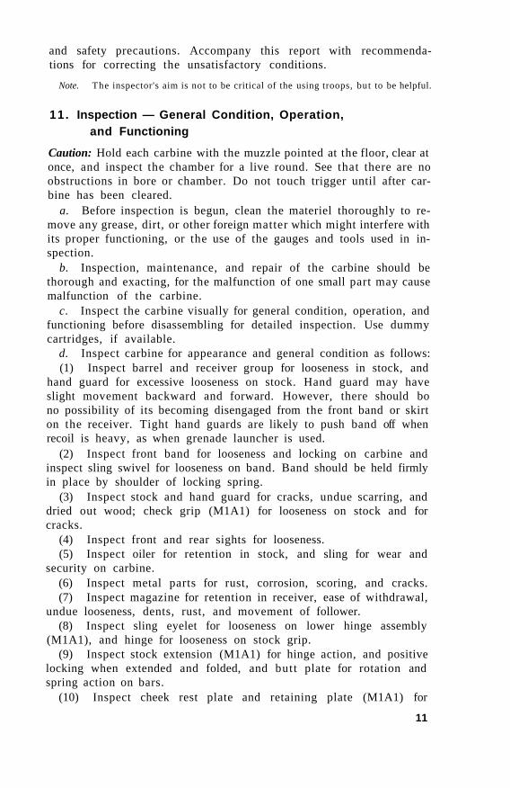
and safety precautions. Accompany this report with recommendations for correcting the unsatisfactory conditions.
Note. The inspector's aim is not to be critical of the using troops, but to be helpful.
11. Inspection — General Condition, Operation, and Functioning
Caution: Hold each carbine with the muzzle pointed at the floor, clear at once, and inspect the chamber for a live round. See that there are no obstructions in bore or chamber. Do not touch trigger until after carbine has been cleared.
a. Before inspection is begun, clean the materiel thoroughly to remove any grease, dirt, or other foreign matter which might interfere with its proper functioning, or the use of the gauges and tools used in inspection.
b. Inspection, maintenance, and repair of the carbine should be thorough and exacting, for the malfunction of one small part may cause malfunction of the carbine.
c. Inspect the carbine visually for general condition, operation, and functioning before disassembling for detailed inspection. Use dummy cartridges, if available.
d. Inspect carbine for appearance and general condition as follows: (1) Inspect barrel and receiver group for looseness in stock, and
hand guard for excessive looseness on stock. Hand guard may have slight movement backward and forward. However, there should bo no possibility of its becoming disengaged from the front band or skirt on the receiver. Tight hand guards are likely to push band off when recoil is heavy, as when grenade launcher is used.
(2) Inspect front band for looseness and locking on carbine and inspect sling swivel for looseness on band. Band should be held firmly in place by shoulder of locking spring.
(3) Inspect stock and hand guard for cracks, undue scarring, and dried out wood; check grip (M1A1) for looseness on stock and for cracks.
(4) Inspect front and rear sights for looseness. (5) Inspect oiler for retention in stock, and sling for wear and
security on carbine. (6) Inspect metal parts for rust, corrosion, scoring, and cracks. (7) Inspect magazine for retention in receiver, ease of withdrawal,
undue looseness, dents, rust, and movement of follower. (8) Inspect sling eyelet for looseness on lower hinge assembly
(M1A1), and hinge for looseness on stock grip. (9) Inspect stock extension (M1A1) for hinge action, and positive
locking when extended and folded, and butt plate for rotation and spring action on bars.
(10) Inspect cheek rest plate and retaining plate (M1A1) for
11
Manual Provided by eMilitary Manuals-http://www.emilitarymanuals.com
looseness on bars, and cheek rest plate cover for wrinkles, scoring, and dried out leather.
(11) Inspect barrel. e. With dummy cartridges in the magazine, retract and release
the operating slide, to load and eject the dummy cartridges. During the operation, inspect the following points:
(1) Smooth functioning of operating slide and bolt. They should reciprocate smoothly and easily, without undue looseness.
(2) Complete locking of bolt, and forward movement of operating slide. The slide should continue to move forward about 5/16 inch after the bolt is fully locked. The same free movement should take place at the start of the rearward movement of the slide, before rotation of the bolt begins.
(3) Grip of extractor on cartridge and function of ejector. Extractor should grip base of cartridge firmly and ejector should throw it off the bolt as soon as front end of cartridge is clear of the receiver. If cartridge is not extracted the extractor claw may be damaged, or extractor plunger or spring broken or missing. Failure to eject may be caused by a broken ejector or a weak or broken ejector spring. If dummy cartridges are not available, operate parts individually, and test spring action.
(4) Chambering of cartridge. The bolt should chamber the cartridge smoothly when released. If bullet ramp on receiver or barrel is rough, or magazine loose so that it tips forward, the bullet may bind on ramp or be deflected upward during chambering and strike the top of the barrel and cause a stoppage.
(5) Position of cartridge in mouth of magazine. If magazine follower does not position cartridge fully up against lips of magazine, the magazine spring may be weak or broken, or the tube or follower dented, rusted, or burred, or the magazine incorrectly assembled. If dummy cartridges are not available, depress follower to bottom of tube and then allow it to rise. Inspect for smooth and positive functioning.
(6) Engagement of sear with hammer. The sear should engage with sear notch in hammer when bolt is about halfway retracted. A crisp click may be heard as sear slides forward into the sear notch in hammer under force of sear spring. Retract the bolt fully to insure complete engagement and retention of sear. If click is not heard or trigger pull appears to be light or excessively heavy, examine sear and sear notch in hammer for wear, burs, foreign matter in sear notch, or weak or broken sear spring. Trigger pull should not be under 5 pounds or over 7 pounds. (See par. 13b.)
(7) Engagement of sear when trigger is not released. The sear should engage and hold the hammer when the trigger is held back and the slide operated rapidly. Test by grasping the carbine by the grip of the stock with the left hand with index finger on the trigger. Pull the trigger all the way to the rear and hold in that position. Grasp the operating slide handle with the right hand and move the bolt back and
12
Manual Provided by eMilitary Manuals-http://www.emilitarymanuals.com
forth rapidly five or six times. Release the operating slide handle in the forward position, release the trigger, allowing it to move fully forward, and then pull it again. If the hammer does not fall, it has jarred out of engagement with the sear and followed the bolt forward. If this is the case, the carbine may fire fullautomatic and the firing mechanism should be inspected for worn or faulty parts.
(8) Carbines with automatic tendencies. Carbines with automatic tendencies can be detected by extremely light or short pulls on the trigger. If, during firing, the trigger is held back fully during cocking and the bolt allowed to return to battery before releasing the trigger, tendency to automatic is detected by releasing the trigger very slowly until the sear is heard to snap. On "automatic" carbines the hammer will often fall at this point, or shock of counterrecoil will jar it off.
f. Inspect functioning of the parts given below as indicated. (1) Bolt. With operating slide assembled to bolt, and spring and
guide disassembled from slide, reciprocate bolt both slowly and rapidly by means of the operating slide handle. The bolt and slide should move freely in their guideways. The bolt will check slightly as it rides over the hammer on its rearward movement. If binding of bolt and slide is apparent, disengage slide from bolt and function individually to ascertain point of binding. Burs may occur in bolt or operating slide guideways, on bolt or operating slide. The cocking cam on hammer and bolt, or the tang of the firing pin and its mating cam in receiver may be burred. Remove such burs by stoning to a polish, with a fine grained sharpening stone.
(2) Trigger. Trigger should move forward under force of trigger spring when released from rearward position. If trigger does not move forward positively, trigger spring may be broken, disengaged, or bent. Trigger hang is also caused by old type triggers with the 4° angle on the forward face of the pedestal. Test trigger pull as explained in paragraph 13.
(3) Safety. The safety should slide without undue interference. It should block trigger when pushed fully to right and release trigger when pushed fully to left and it should be positively retained in either position. (See par. 33f.)
(4) Magazine catch. The magazine catch should return to position when released after it is pressed to the left to disengage magazine. If action is sluggish, examine for burs, foreign matter, broken spring, lack of lubrication, or damaged retainer plunger or spring.
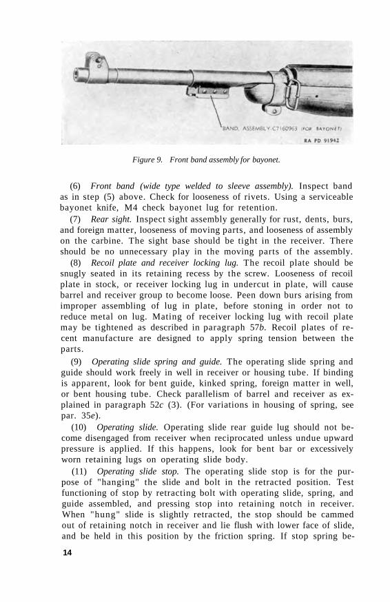
(5) Front band (narrow and wide type). The front band should be lying securely behind shoulder of locking spring when screw is drawn down snugly and locking spring engaged positively. If spring will not. depress, inspect for foreign matter in seating recess in stock. If spring does not engage positively with front band, check for bent spring or worn or burred locking shoulder (fig. 9), or excessive wood on stock or hand guard. (See par. 56c.)
13
Manual Provided by eMilitary Manuals-http://www.emilitarymanuals.com
Figure 9. Front band assembly for bayonet.
(6) Front band (wide type welded to sleeve assembly). Inspect band as in step (5) above. Check for looseness of rivets. Using a serviceable bayonet knife, M4 check bayonet lug for retention.
(7) Rear sight. Inspect sight assembly generally for rust, dents, burs, and foreign matter, looseness of moving parts, and looseness of assembly on the carbine. The sight base should be tight in the receiver. There should be no unnecessary play in the moving parts of the assembly.
(8) Recoil plate and receiver locking lug. The recoil plate should be snugly seated in its retaining recess by the screw. Looseness of recoil plate in stock, or receiver locking lug in undercut in plate, will cause barrel and receiver group to become loose. Peen down burs arising from improper assembling of lug in plate, before stoning in order not to reduce metal on lug. Mating of receiver locking lug with recoil plate may be tightened as described in paragraph 57b. Recoil plates of recent manufacture are designed to apply spring tension between the parts.
(9) Operating slide spring and guide. The operating slide spring and guide should work freely in well in receiver or housing tube. If binding is apparent, look for bent guide, kinked spring, foreign matter in well, or bent housing tube. Check parallelism of barrel and receiver as explained in paragraph 52c (3). (For variations in housing of spring, see par. 35e).
(10) Operating slide. Operating slide rear guide lug should not become disengaged from receiver when reciprocated unless undue upward pressure is applied. If this happens, look for bent bar or excessively worn retaining lugs on operating slide body.
(11) Operating slide stop. The operating slide stop is for the purpose of "hanging" the slide and bolt in the retracted position. Test functioning of stop by retracting bolt with operating slide, spring, and guide assembled, and pressing stop into retaining notch in receiver. When "hung" slide is slightly retracted, the stop should be cammed out of retaining notch in receiver and lie flush with lower face of slide, and be held in this position by the friction spring. If stop spring be-
14
Manual Provided by eMilitary Manuals-http://www.emilitarymanuals.com
comes broken, stop may catch in retaining notch when slide reciprocates. If nose of stop or edge of retaining notch becomes worn, or friction spring becomes weak or broken, stop is likely to slip and fail to bang bolt. If there is insufficient friction on stop, it may jar into the notch and "hang" the bolt when the carbine functions. If such is the case, replace stop or spring or send carbine to base shop or arsenal for repair.
12. Operating Inspection, Carbines, cal. .30, M2 and M3
With carbine fully assembled and unloaded and safety pushed to left fire position, test for functioning as follows:
a. Pull selector fully to rear to place mechanism in the semiautomatic position. Then, with trigger released, fully retract bolt to cock the hammer, and allow bolt to spring forward. Hammer should not fall, until trigger is pulled.
b. With trigger held back, cock the hammer as above and allow bolt to spring forward. Hammer should not fall until trigger is released and then pulled.
c. With trigger released, retract bolt to cock hammer, and allow bolt to spring forward. Push selector forward to place mechanism in full automatic position. Hammer should not fall until trigger is pulled.
d. With selector still forward, and trigger held back, retract bolt to cock hammer, then ease bolt forward slowly. The hammer should not fall until the bolt is fully locked. The hammer can distinctly be heard striking the firing pin.
e. Test safety with selector in both positions. It should not be possible to release the hammer with safety pushed to right.
Note. If the trigger is not released during firing, and the selector is pushed forward to the full automatic position, the hammer will fall. Trigger should always be released when shifting from semiautomatic to full automatic fire or vice versa.
13. Trigger Pull
a. GENERAL. (1) Test trigger pull for smoothness and for pressure exerted. Trigger pull should be clean, without creep, smooth in action; and the force exerted to release hammer should be more than 5 pounds and less than 7 pounds (See b below.) If pull is rough, or not within specified limits, or creep is present, it indicates that there is wear or burs on sear nose, hammer notch, or top of trigger lip, or interference between trigger and housing.
Note. The word "creep" is interpreted to mean any perceptible movement in the trigger pull between the time the slack is taken up and the hammer is released, with pressure applied to the trigger at a uniform rate of increase over a period of 10 seconds or more.
(2) The inspector, in testing trigger pull of carbines in the hands of troops, should have hooks and weights, which will combine to 5 and 7 pounds.
15
Manual Provided by eMilitary Manuals-http://www.emilitarymanuals.com
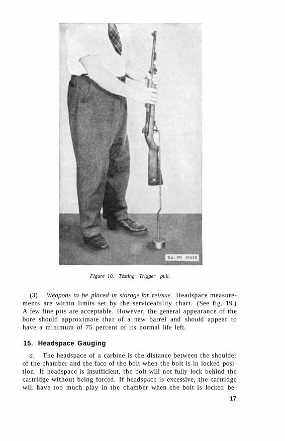
b. TESTING TRIGGER PULL (fig. 10). Note that safety is disengaged and pushed all the way to the left, and that carbine is cocked. Have the weights resting on the floor or ground, and insert the hook of trigger weight wire through the trigger housing guard bow to bear on the trigger so that pressure is applied 1/4 inch from lower end or tip of trigger. With the barrel of the carbine held vertically, raise the weight from the floor as gently as possible. If 5-pound weight pulls the trigger to release the hammer, or the 7-pound weight fails to pull the trigger to release the hammer, correct the carbine or forward to a base shop or arsenal for correction. (See par. 33d.) The only correction allowed in field repair is the selective assembly of hammer, hammer spring, sear, and/or trigger or all four until the required pull is obtained. Take care during the test to see that the wire contacts the trigger only and does not rub against the trigger housing or stock, and that wire and axis of bore are perpendicular to the floor.
Note. Each time weights are applied to the trigger, cock the weapon again, otherwise sear may be partially disengaged from hammer. This will result in a false reading next time weights are applied.
14. Barrel and Receiver Group
a. Inspect the barrel visually to determine the condition of the bore. Make a gauge inspection to determine the amount of wear that has taken place in the chamber, or in related parts affecting headspace.
b. Gauge inspection offers no problems, as the tolerances are definitely set; however, classification of barrels by visual inspection is a matter of individual skill and judgment and therefore offers many problems. Care in interpretation and application of the standards contained herein will aid in arriving at a uniform point of rejection. The point at which a barrel is rejected by visual inspection varies with the disposition to be made of the rifle immediately following inspection. The various possibilities are divided into three classes:
(1) Weapons in hands of troops. Headspace measurements should be within the limits set by serviceability chart. (See fig. 19.) If the barrel is pitted to the extent that the sharpness of the lands is affected, or if it has a pit or pits in the lands or grooves large enough to permit the passage of gas past the bullet, it is to be scrapped. A pit the width of a land or groove and 3/8 inch long or longer indicates this condition. Examine barrel for mechanical damage and examine the chamber for deep pits that would seriously affect extraction.
(2) Weapons to accompany troops overseas. Headspace measurements are within limits set by the serviceability chart. (See fig. 19.) Examine barrel for pits or mechanical damage. A barrel having fine scattered pits but with sharp edges on the lands may be considered serviceable. Only barrels which show excessive wear, developed pits, or pits cutting the lands are considered unserviceable for oversea shipment.
16
Manual Provided by eMilitary Manuals-http://www.emilitarymanuals.com
Figure 10. Testing Trigger pull.
(3) Weapons to be placed in storage for reissue. Headspace measurements are within limits set by the serviceability chart. (See fig. 19.) A few fine pits are acceptable. However, the general appearance of the bore should approximate that of a new barrel and should appear to have a minimum of 75 percent of its normal life left.
15. Headspace Gauging
a. The headspace of a carbine is the distance between the shoulder of the chamber and the face of the bolt when the bolt is in locked position. If headspace is insufficient, the bolt will not fully lock behind the cartridge without being forced. If headspace is excessive, the cartridge will have too much play in the chamber when the bolt is locked be-
17
Manual Provided by eMilitary Manuals-http://www.emilitarymanuals.com
hind it. Either condition is unsafe. As component parts of the carbine are manufactured to close tolerances and headspace is carefully checked at manufacture, a variation usually is due to wear and causes excessive headspace to develop. However, assembly of parts with maximum tolerances may result in either excessive or insufficient headspace.
b. Excessive headspace due to wear may be caused by advanced chamber shoulder, worn faces of bolt, worn locking lugs on bolt, or worn locking shoulders in the receiver.
c. Test headspace with gauge (fig: 54), as follows:
(1) Clean bore, chamber of barrel, and operating parts thoroughly, wipe dry, and inspect for metal fouling or foreign matter. Operate the mechanism a few times to see that bolt closes and locks smoothly on an empty chamber.
(2) Retract and hang the bolt by means of the slide stop. Place the headspace gauge on the face of the bolt, gripped by the extractor. Be sure that gauge is perfectly clean and dry.
(3) Retract the bolt slightly to disengage the operating slide stop, and allow the bolt to move slowly forward to the locked position so the gauge enters the chamber of the barrel. If the bolt locks fully on the maximum gauge, the headspace is excessive and the carbine unserviceable. Lock the bolt completely when the minimum gauge is used.
Caution: Do not force, or allow bolt to close sharply under spring propulsion.
(4) Pull back bolt and remove gauge. Note. See serviceability chart (fig. 19) for proper headspace gauge. Forward head
space gauges to an arsenal once a year for checking.
16. Magazine
Test magazine for retention in carbine. Inspect follower for smooth movement in tube under force of spring by depressing follower and allowing it to rise. If follower does not depress and rise smoothly to the top of tube under spring action, look for burs, rust, and corrosion in tube, reversed follower, deformed, or burred tube or follower, and weak, broken, or reversed spring. Apply pressure evenly on the follower when depressing in order not to "cock" or rotate it in the tube.
17. Adjustable Rear Sight Assembly
a. Inspect sight assembly generally for rust, dents, burs, and foreign matter, looseness of moving parts, and looseness of assembly on the carbine. The sight base should be tight in receiver. There should be no unnecessary play in the moving parts of the assembly.
b. Check sight base for looseness and bent, burred, or shiny wings. Check ramp for worn or burred guideways and index ball retention
18

Manual Provided by eMilitary Manuals-http://www.emilitarymanuals.com
notches in floor. Check notches for foreign matter. Check index plate on rear face of ramp for security and setting.
c. Check windage screw for wear of threads, burs, and looseness, security, and staking. With ramp centered in sight base, press windage screw knob to left and release, to test spring action of index ball on knob. There should be approximately 0.005 inch lateral movement of the knob, due to pressure and index spring action.
d. With ramp centered in sight base, attempt to move lower end of ramp from side to side. There should be practically no lateral movement. If very noticeable movement is present, it indicates worn threads on either windage screw or ramp, or both. Press rear end of ramp down and release, to check spring action of ramp guide plunger.
19
Manual Provided by eMilitary Manuals-http://www.emilitarymanuals.com
SECTION III
TOOLS, GAUGES, AND FIXTURES
18. General
a. The special tools and gauges for the inspection, disassembly, assembly, and repair of the carbine, cal. .30, M l , M1A1, and M2 are listed on ORD 6 SNL B-20.
b. Common tools (screw drivers, drifts, pliers, hammers, stones, etc.) which normally are used in maintenance and repair, are standard 1o maintenance organizations and are listed in appropriate standard nomenclature lists.
c. Return all field service inspection gauges to an arsenal for checking once each year.
19. Special Tools
a. TOOL, DISASSEMBLING, BOLT 41-T-3019-625 (fig. 11). This tool consists of a concave body to receive the bolt. A thumb screw set at an angle applies pressure when tightened, to the right locking lug of the bolt. A small stud on the inside forward end of the tool bears against the ejector, and a pivoted pawl, for depressing the ejector plunger, is on the upper forward portion of the tool.
b. TOOL, REMOVING, TRIGGER SPRING, ASSEMBLY 41-T-3318
(fig. 11). This tool consists of a hollow tube 0.3135 inch diameter with a handle projecting at a 90° angle from the tube.
c. TOOL, ASSEMBLING, FRONT SIGHT 41-T-3017-625 (fig. 12).
The front sight assembling tool is a hexagonal shaped driver with the interior drilled which acts as a guide to receive the barrel. A spring loaded plunger protrudes from the front and when the plunger is bottomed it acts as a stop to align the hole for the front sight pin. A cut on the upper front portion of the tool provides a bearing surface for driving on the sight, and also makes it possible to rotate the sight on the barrel for alignment of the key and keyway.
d. TOOL, REMOVING, FRONT SIGHT 41-T-3318-500 (fig. 12). This tool consists of a steel frame slotted on one end to fit over the band to the rear of the front sight. On the other end of the tool is a jack screw with a floating pilot which seats in the muzzle of the barrel.
e. TOOL, GAS CYLINDER RECONDITIONING, COMPLETE 41-T-3164
(fig. 11). (1) The gas cylinder reconditioning tool consists of —
20


![m1 Carbine[1]](https://img.pdfslide.net/doc/110x75/553d5480550346724a8b45fb/m1-carbine1.jpg)