Embed Size (px)
Citation preview

Keeping the World Flowing
Manual Quarter-turn Gear Operators
242 SeriesManual Quarter-turn Gear Operators
The 242 range has been designed to optimise robustness and durability, whilst minimising non-structural mass and reducing the overall gearbox envelope by using the latest lean engineering principles and analytical design tools. The 242 series is based on the design and quality of the FB series which was designed to meet strict specifications. The 242’s simple, rugged construction makes it the gearbox of choice for low torque applications.
Application
The 242 series quarter-turn worm gearboxes are intended for the operation of ball, butterfly, plug and any other quarter-turn valves. They are well suited for applications in power, waterworks, gas pipelines, HVAC and most general industrial applications.
Features
• Cast handwheels (on smaller sizes)
• PTFE thrust washers
• Cast iron housing
• Ductile iron quadrant
• Stroke 0-90° (±5° adjustable at open and closed)
• Pre-applied silicon seal on stop bolts
• Special protection of the input shaft
• Stainless steel position indicator
• Zinc plated fasteners
Environmental Specification
• Sealed to IP67
• Temperature range: -40 °C to 120 °C
Options
• Padlockable flange
• Stainless steel input shaft & fasteners
• Namur mounting
• Memory stop
• Westlock mounting
• IP68
A4 US
US
A4
US
A4
A4 US
242 Series
242 Series
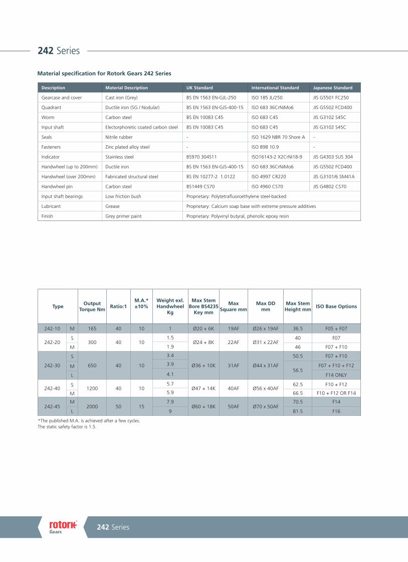
TypeOutput
Torque NmRatio:1
M.A.*±10%
Weight exl. Handwheel
Kg
Max Stem Bore BS4235
Key mm
Max Square mm
Max DD mm
Max Stem Height mm
ISO Base Options
242-10 M 165 40 10 1 Ø20 + 6K 19AF Ø26 x 19AF 36.5 F05 + F07
242-20S
300 40 101.5
Ø24 + 8K 22AF Ø31 x 22AF40 F07
1.9 46 F07 + F10M
242-30
S
650 40 10
3.4
Ø36 + 10K 31AF Ø44 x 31AF
50.5 F07 + F10
3.956.5
F07 + F10 + F12M
4.1 F14 ONLYL
242-40S
1200 40 105.7
Ø47 + 14K 40AF Ø56 x 40AF62.5 F10 + F12
5.9 66.5 F10 + F12 OR F14M
242-45M
2000 50 157.9
Ø60 + 18K 50AF Ø70 x 50AF70.5 F14
L 9 81.5 F16
Material specification for Rotork Gears 242 Series
Description Material Description UK Standard International Standard Japanese Standard
Gearcase and cover Cast iron (Grey) BS EN 1563 EN-GJL-250 ISO 185 JL/250 JIS G5501 FC250
Quadrant Ductile iron (SG / Nodular) BS EN 1563 EN-GJS-400-15 ISO 683 36CrNiMo6 JIS G5502 FCD400
Worm Carbon steel BS EN 10083 C45 ISO 683 C45 JIS G3102 S45C
Input shaft Electorphoretic coated carbon steel BS EN 10083 C45 ISO 683 C45 JIS G3102 S45C
Seals Nitrile rubber - ISO 1629 NBR 70 Shore A -
Fasteners Zinc plated alloy steel - ISO 898 10.9 -
Indicator Stainless steel BS970 304S11 ISO16143-2 X2CrNi18-9 JIS G4303 SUS 304
Handwheel (up to 200mm) Ductile iron BS EN 1563 EN-GJS-400-15 ISO 683 36CrNiMo6 JIS G5502 FCD400
Handwheel (over 200mm) Fabricated structural steel BS EN 10277-2 1.0122 ISO 4997 CR220 JIS G3101/6 SM41A
Handwheel pin Carbon steel BS1449 CS70 ISO 4960 CS70 JIS G4802 CS70
Input shaft bearings Low friction bush Proprietary: Polytetrafluoroethylene steel-backed
Lubricant Grease Proprietary: Calcium soap base with extreme pressure additives
Finish Grey primer paint Proprietary: Polyvinyl butyral, phenolic epoxy resin
*The published M.A. is achieved after a few cycles.The static safety factor is 1.5.
A4 US
Keeping the World Flowing
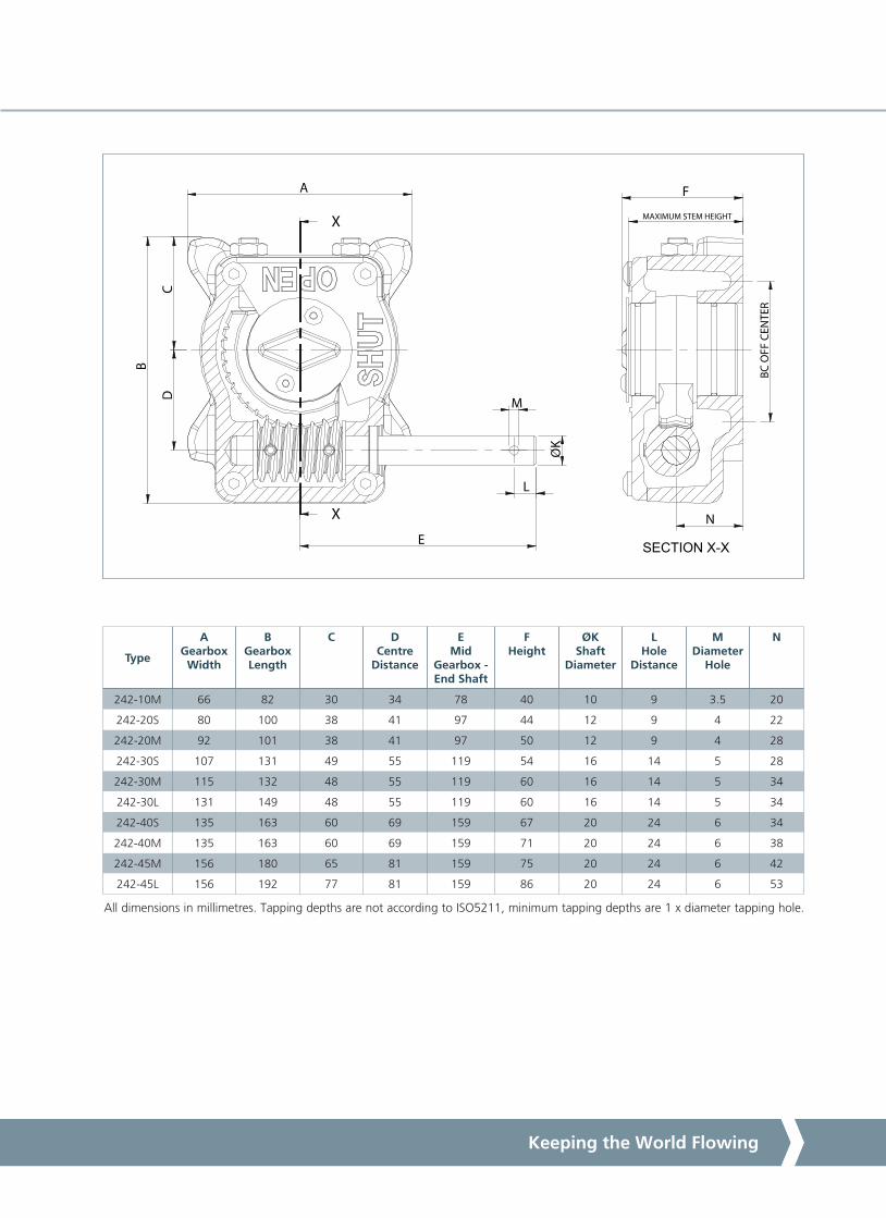
Type
A Gearbox Width
B Gearbox Length
C D Centre
Distance
E Mid
Gearbox - End Shaft
F Height
ØK Shaft
Diameter
L Hole
Distance
M Diameter
Hole
N
242-10M 66 82 30 34 78 40 10 9 3.5 20
242-20S 80 100 38 41 97 44 12 9 4 22
242-20M 92 101 38 41 97 50 12 9 4 28
242-30S 107 131 49 55 119 54 16 14 5 28
242-30M 115 132 48 55 119 60 16 14 5 34
242-30L 131 149 48 55 119 60 16 14 5 34
242-40S 135 163 60 69 159 67 20 24 6 34
242-40M 135 163 60 69 159 71 20 24 6 38
242-45M 156 180 65 81 159 75 20 24 6 42
242-45L 156 192 77 81 159 86 20 24 6 53
All dimensions in millimetres. Tapping depths are not according to ISO5211, minimum tapping depths are 1 x diameter tapping hole.
X
X
SECTION X-X
A
B
CD
E
L
K
MAXIMUM STEM HEIGHT
F
BC O
FF C
ENTE
R
M
N
O
PUB099-001-00Issue 11/17
As part of a process of on-going product development, Rotork reserves the right to amend and change specifications without prior notice. Published data may be subject to change. For the very latest version release, visit our website at www.rotork.com
The name Rotork is a registered trademark. Rotork recognises all registered trademarks. Published and produced in the UK by Rotork Controls Limited. RGSG1117
Rotork is a corporate member of the Institute of Asset Management
242 SeriesManual Quarter-turn Gear Operators
1000
900
800
700
600
500
400
300250200
200 300 360 400RIM Effort in N
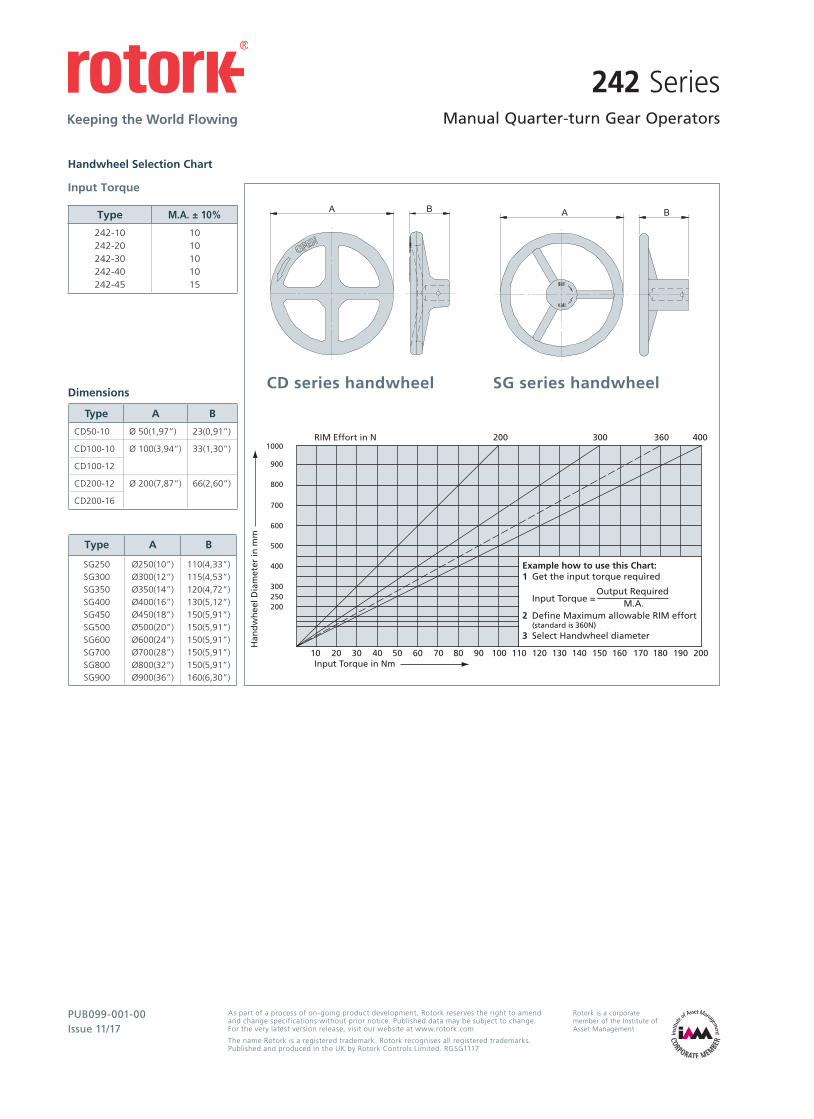
Example how to use this Chart:1 Get the input torque required Output Required Input Torque = M.A.2 Define Maximum allowable RIM effort (standard is 360N)3 Select Handwheel diameter
Han
dw
hee
l Dia
met
er in
mm
Input Torque in Nm10 20 30 40 50 60 70 80 90 100 110 120 130 140 150 160 170 180 190 200
Handwheel Selection Chart
Dimensions
Type M.A. ± 10%
242-10242-20242-30242-40242-45
1010101015
Input Torque
Type A B
SG250SG300SG350SG400SG450SG500SG600SG700SG800SG900
Ø250(10”)Ø300(12”)Ø350(14”)Ø400(16”)Ø450(18”)Ø500(20”)Ø600(24”)Ø700(28”)Ø800(32”)Ø900(36”)
110(4,33”)115(4,53”)120(4,72”)130(5,12”)150(5,91”)150(5,91”)150(5,91”)150(5,91”)150(5,91”)160(6,30”)
Type A B
CD50-10 Ø 50(1,97”) 23(0,91”)
CD100-10 Ø 100(3,94”) 33(1,30”)
CD100-12
CD200-12 Ø 200(7,87”) 66(2,60”)
CD200-16
CD series handwheel SG series handwheel
A4US
US
A4
US A4
US
A4