Embed Size (px)
Citation preview
GSMio
Instruction manual
2
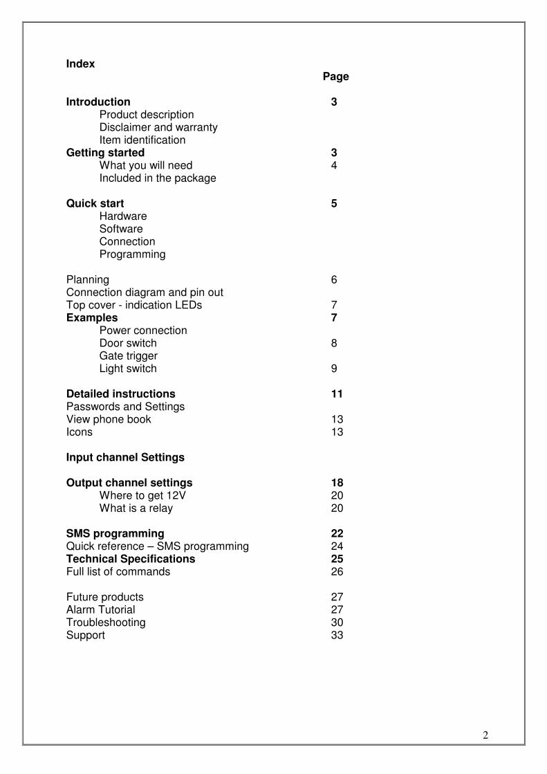
Index Page Introduction 3
Product description Disclaimer and warranty Item identification
Getting started 3 What you will need 4 Included in the package
Quick start 5 Hardware Software Connection Programming Planning 6 Connection diagram and pin out Top cover - indication LEDs 7 Examples 7
Power connection Door switch 8 Gate trigger Light switch 9
Detailed instructions 11 Passwords and Settings View phone book 13 Icons 13 Input channel Settings Output channel settings 18
Where to get 12V 20 What is a relay 20
SMS programming 22 Quick reference – SMS programming 24 Technical Specifications 25 Full list of commands 26 Future products 27 Alarm Tutorial 27 Troubleshooting 30 Support 33
3
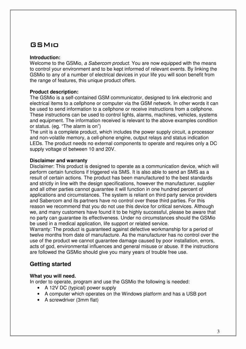
GSMioGSMioGSMioGSMio Introduction: Welcome to the GSMio, a Sabercom product. You are now equipped with the means to control your environment and to be kept informed of relevant events. By linking the GSMio to any of a number of electrical devices in your life you will soon benefit from the range of features, this unique product offers. Product description: The GSMio is a self-contained GSM communicator, designed to link electronic and electrical items to a cellphone or computer via the GSM network. In other words it can be used to send information to a cellphone or receive instructions from a cellphone. These instructions can be used to control lights, alarms, machines, vehicles, systems and equipment. The information received is relevant to the above examples condition or status. (eg. “The alarm is on”) The unit is a complete product, which includes the power supply circuit, a processor and non-volatile memory, a cell-phone engine, output relays and status indication LEDs. The product needs no external components to operate and requires only a DC supply voltage of between 10 and 20V. Disclaimer and warranty Disclaimer: This product is designed to operate as a communication device, which will perform certain functions if triggered via SMS. It is also able to send an SMS as a result of certain actions. The product has been manufactured to the best standards and strictly in line with the design specifications, however the manufacturer, supplier and all other parties cannot guarantee it will function in one hundred percent of applications and circumstances. The system is reliant on third party service providers and Sabercom and its partners have no control over these third parties. For this reason we recommend that you do not use this device for critical services. Although we, and many customers have found it to be highly successful, please be aware that no party can guarantee its effectiveness. Under no circumstances should the GSMio be used in a medical application, life support or related service. Warranty: The product is guaranteed against defective workmanship for a period of twelve months from date of manufacture. As the manufacturer has no control over the use of the product we cannot guarantee damage caused by poor installation, errors, acts of god, environmental influences and general misuse or abuse. If the instructions are followed the GSMio should give you many years of trouble free use.
Getting started What you will need. In order to operate, program and use the GSMio the following is needed:
• A 12V DC (typical) power supply
• A computer which operates on the Windows platform and has a USB port
• A screwdriver (3mm flat)
4
The following will help:
• Some, but limited electronic knowledge. (Ability to change a mains plug, jumpstart a car)
• A multi-meter
• Side cutters If you feel that any of the steps are outside of your ability please consult a qualified technician or electrician. You can contact Sabercom for advice or most alarm installation technicians will be able to help.
For more information please consult the following sections of this manual.
� Where to get 12V DC � What is a relay? � Glossary
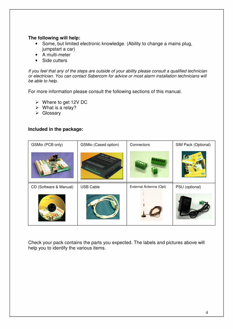
Included in the package:
Check your pack contains the parts you expected. The labels and pictures above will help you to identify the various items.
GSMio (PCB only)
GSMio (Cased option)
CD (Software & Manual)
USB Cable
External Antenna (Opt)
Connectors
SIM Pack (Optional)
PSU (optional)
5
Quick Start (New unit) Software
1. Insert the CD into the ROM drive of your PC. (See “PC specifications” to check the compatibility of your PC.)
2. Follow the onscreen instructions to install the software. Connection (USB)
1. Connect the USB cable between your GSMio unit and one of the USB ports on your PC.
2. Your PC should automatically install the USB drivers. If it does not, refer to troubleshooting to manually install the USB drivers.
Hardware
1. Ensure the SIM PIN (Personal Identification Number) on your SIM card is either disabled or set to 9176.
2. Insert the SIM card in slot 1 on the underside of the GSMio unit. 3. Connect the GSMio to a 12V DC power source. Pin 1 + and 2 - of the
connector block. [Actual voltage range is 10V to 20V DC] (See “where to get 12V from” if you do not have a 12V DC supply handy.)
4. After a few moments the Status LED should flash. If not, disconnect power, check the steps above and reconnect power.
Programming
1. Start the GSMio software by double clicking the GSMio icon on your desktop.
2. Once the GSMio software screen opens click on the “Check Comms” icon, to check the connection is active.
3. Enter the relevant fields into the Programming fields on the GSMio software screens.
4. Save the programming information to the GSMio by clicking the “Send to GSMio” icon. A status indicator will show the progress and result of the upload.
5. Disconnect the GSMio from the PC and 12V supply. Please note, the GSMio must be turned off and back on for the new settings to take effect.
6. Connect its input and outputs as per your application. Finally reconnect 12V power.
7. After the GSMio has logged onto the network it will send the Master Number a message asking for the TIME. Please reply as follows: pass@time 12:45 (Where pass is the password you programmed into the GSMio, @ is the symbol for programming, time followed by a space and then the time in 24
6
hour format. So 9.15pm will be 21:15 Only the : symbol can be used, no
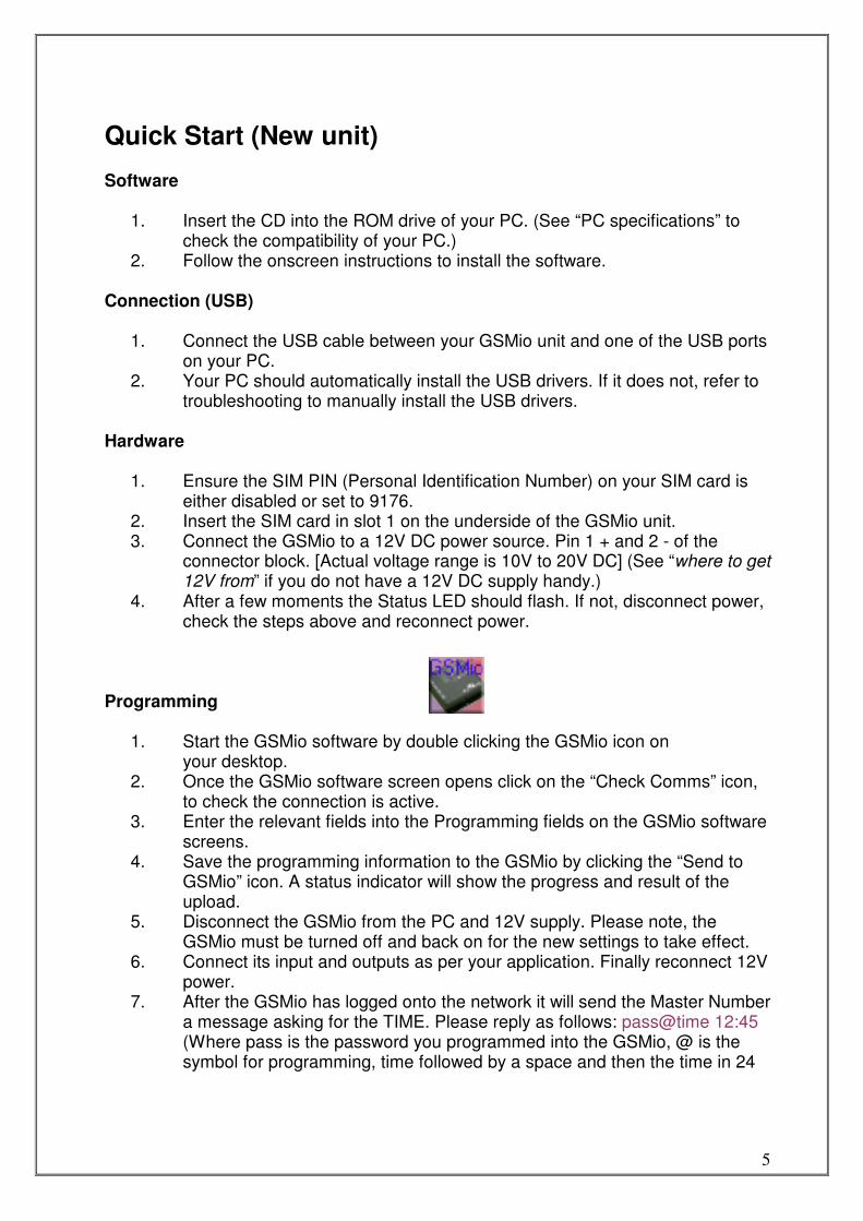
additional spaces etc) Planning: It is a good idea to plan exactly what you want to use the GSMio for and how to connect it to your home or office. Please view the following section and then the examples to get an idea of the practical application of GSMio. Connection diagram and pin out. Pin NoPin NoPin NoPin No NameNameNameName DescriptionDescriptionDescriptionDescription ConnectionConnectionConnectionConnection BlockBlockBlockBlock
1 Pos Positive DC supply 12V Positive (side of battery) 2 way
2 Neg Negative DC supply 0V negative (side of battery) 2 way
3 In 1 Input 1 Input 1 trigger 7 way
4 In 2 Input 2 Input 2 trigger 7 way
5 In 3 Input 3 Input 3 trigger 7 way
6 In 4 Input 4 Input 4 trigger 7 way
7 In 5 Input 5 Input 5 trigger 7 way
8 In 6 Input 6 Input 6 trigger 7 way
9 Pos Positive DC supply Extra Positive supply (for inputs) 7 way
10 Com Common for relays Relay common connection 5 way
11 Out 1 Output 1 Output 1 to common (when on) 5 way
12 Out 2 Output 2 Output 2 to common (when on) 5 way
13 Out 3 Output 3 Output 3 to common (when on) 5 way
14 Out 4 Output 4 Output 4 to common (when on) 5 way
Pin numbering
1 2 3 4 5 6 7 8 9 10 11 12 13 14
7
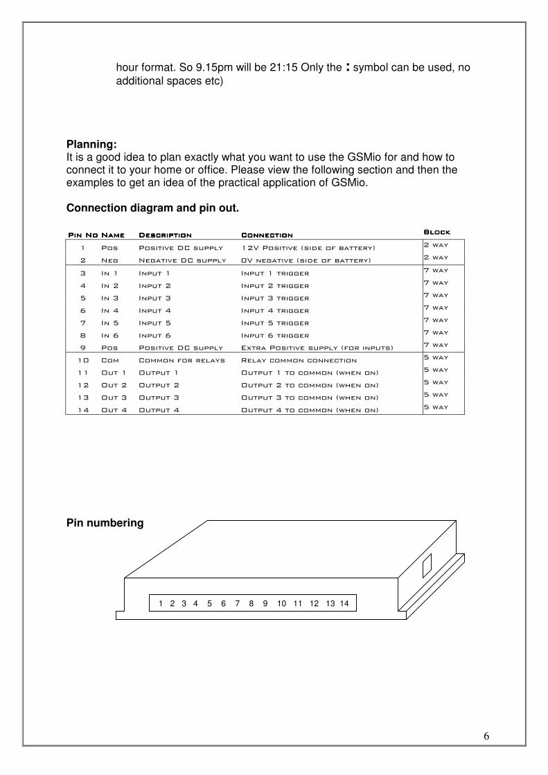
Top cover - indication LEDs
LEDs (light emitting diodes) Power – Glows to indicate power is connected
GSM – Flashes once per second when logged onto a network
Status – Flickers when the unit is sending or receiving
Input 1 to 6 – Glows when the input is on (High)
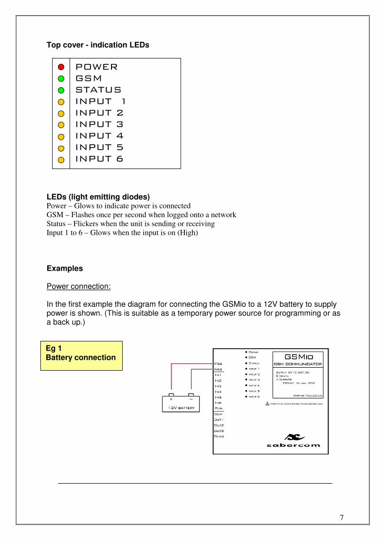
Examples Power connection: In the first example the diagram for connecting the GSMio to a 12V battery to supply power is shown. (This is suitable as a temporary power source for programming or as a back up.)
Eg 1 Battery connection
POWER GSM STATUS INPUT 1 INPUT 2 INPUT 3 INPUT 4 INPUT 5 INPUT 6
8
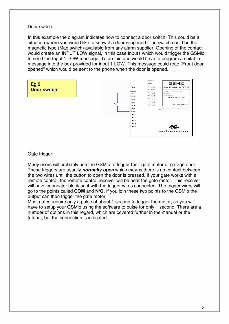
Door switch: In this example the diagram indicates how to connect a door switch. This could be a situation where you would like to know if a door is opened. The switch could be the magnetic type (Mag switch) available from any alarm supplier. Opening of the contact would create an INPUT LOW signal, in this case Input1 which would trigger the GSMio to send the Input 1 LOW message. To do this one would have to program a suitable message into the box provided for input 1 LOW. This message could read “Front door opened” which would be sent to the phone when the door is opened.
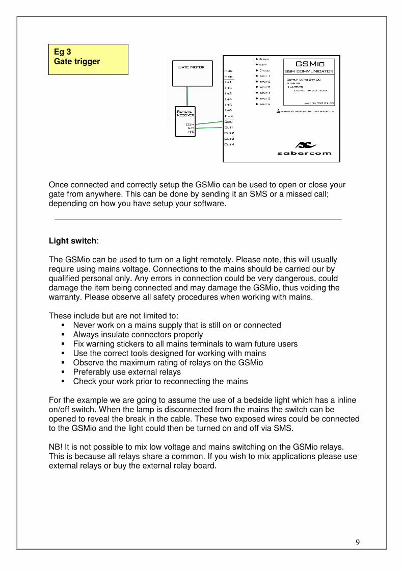
Gate trigger: Many users will probably use the GSMio to trigger their gate motor or garage door. These triggers are usually normally open which means there is no contact between the two wires until the button to open the door is pressed. If your gate works with a remote control, the remote control receiver will be near the gate motor. This receiver will have connector block on it with the trigger wires connected. The trigger wires will go to the points called COM and N/O. If you join these two points to the GSMio the output can then trigger the gate motor. Most gates require only a pulse of about 1 second to trigger the motor, so you will have to setup your GSMio using the software to pulse for only 1 second. There are a number of options in this regard, which are covered further in the manual or the tutorial, but the connection is indicated.
Eg 2 Door switch
9
Once connected and correctly setup the GSMio can be used to open or close your gate from anywhere. This can be done by sending it an SMS or a missed call; depending on how you have setup your software. Light switch: The GSMio can be used to turn on a light remotely. Please note, this will usually require using mains voltage. Connections to the mains should be carried our by qualified personal only. Any errors in connection could be very dangerous, could damage the item being connected and may damage the GSMio, thus voiding the warranty. Please observe all safety procedures when working with mains. These include but are not limited to:
� Never work on a mains supply that is still on or connected � Always insulate connectors properly � Fix warning stickers to all mains terminals to warn future users � Use the correct tools designed for working with mains � Observe the maximum rating of relays on the GSMio � Preferably use external relays � Check your work prior to reconnecting the mains
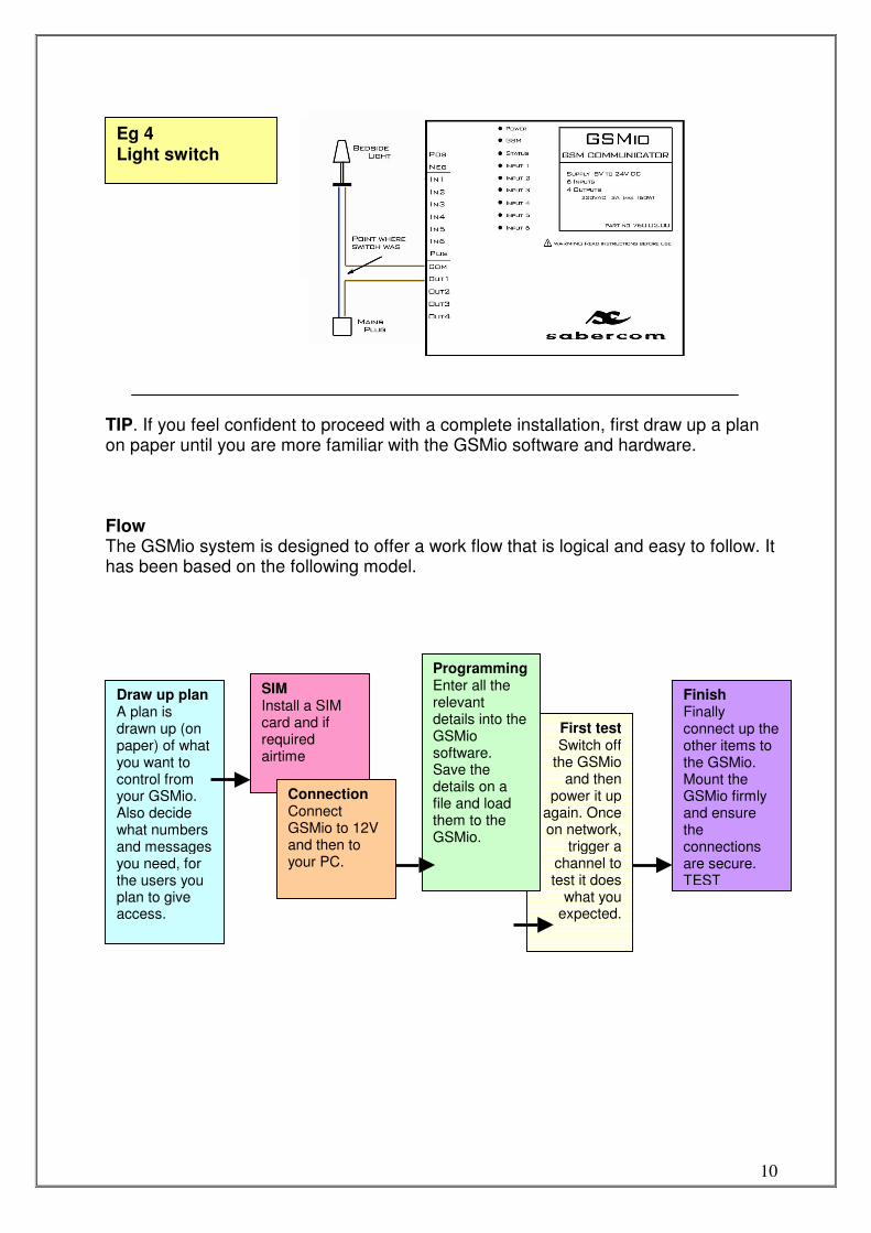
For the example we are going to assume the use of a bedside light which has a inline on/off switch. When the lamp is disconnected from the mains the switch can be opened to reveal the break in the cable. These two exposed wires could be connected to the GSMio and the light could then be turned on and off via SMS. NB! It is not possible to mix low voltage and mains switching on the GSMio relays. This is because all relays share a common. If you wish to mix applications please use external relays or buy the external relay board.
Eg 3 Gate trigger
10
TIP. If you feel confident to proceed with a complete installation, first draw up a plan on paper until you are more familiar with the GSMio software and hardware. Flow The GSMio system is designed to offer a work flow that is logical and easy to follow. It has been based on the following model.
Eg 4 Light switch
Draw up plan A plan is drawn up (on paper) of what you want to control from your GSMio. Also decide what numbers and messages you need, for the users you plan to give access.
SIM Install a SIM card and if required airtime
First testSwitch off
the GSMio and then
power it up again. Once on network,
trigger a channel to test it does
what you expected.
Connection Connect GSMio to 12V and then to your PC.
Programming Enter all the relevant details into the GSMio software. Save the details on a file and load them to the GSMio.
Finish Finally connect up the other items to the GSMio. Mount the GSMio firmly and ensure the connections are secure. TEST
11
Detailed Operating Instructions
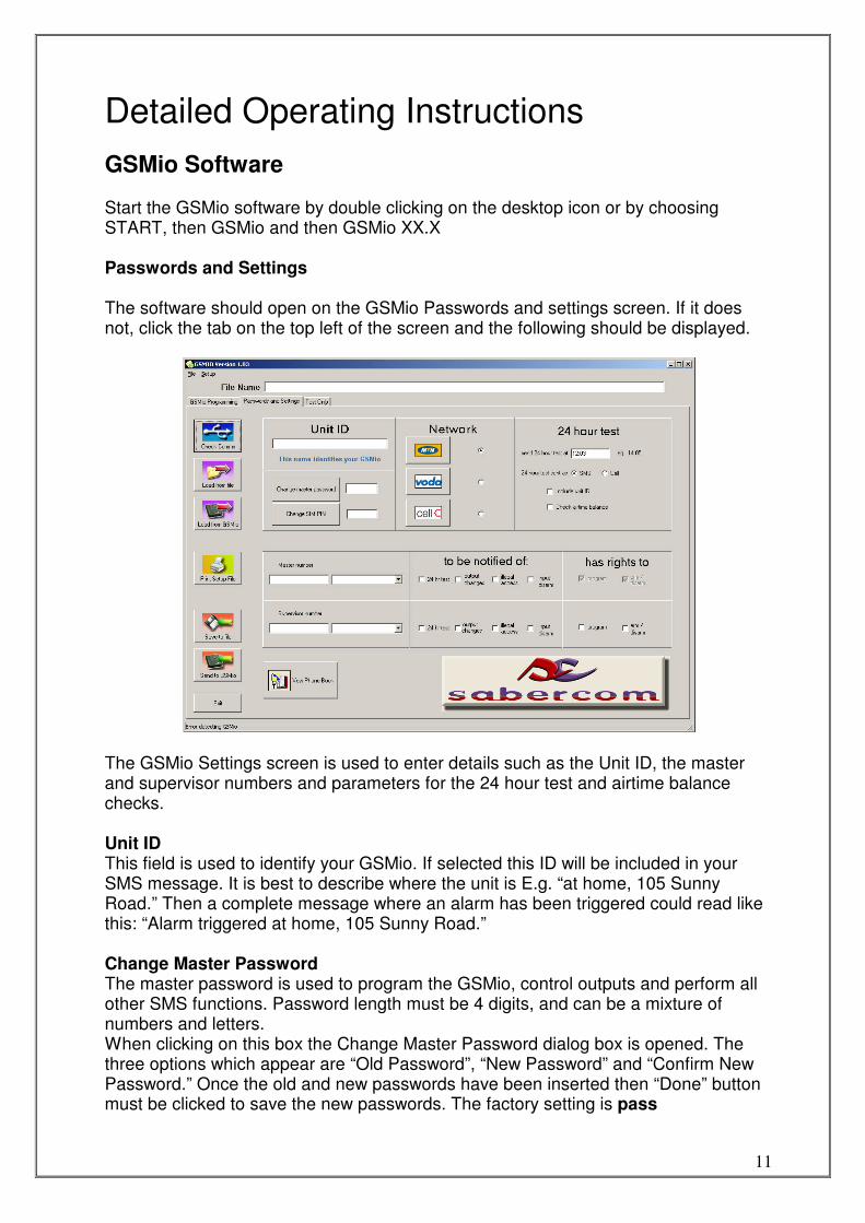
GSMio Software Start the GSMio software by double clicking on the desktop icon or by choosing START, then GSMio and then GSMio XX.X Passwords and Settings The software should open on the GSMio Passwords and settings screen. If it does not, click the tab on the top left of the screen and the following should be displayed.
The GSMio Settings screen is used to enter details such as the Unit ID, the master and supervisor numbers and parameters for the 24 hour test and airtime balance checks. Unit ID This field is used to identify your GSMio. If selected this ID will be included in your SMS message. It is best to describe where the unit is E.g. “at home, 105 Sunny Road.” Then a complete message where an alarm has been triggered could read like this: “Alarm triggered at home, 105 Sunny Road.” Change Master Password The master password is used to program the GSMio, control outputs and perform all other SMS functions. Password length must be 4 digits, and can be a mixture of numbers and letters. When clicking on this box the Change Master Password dialog box is opened. The three options which appear are “Old Password”, “New Password” and “Confirm New Password.” Once the old and new passwords have been inserted then “Done” button must be clicked to save the new passwords. The factory setting is pass
12
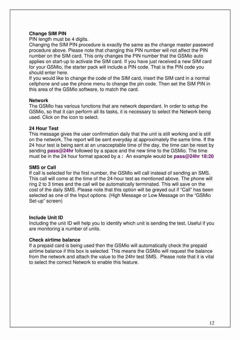
Change SIM PIN PIN length must be 4 digits. Changing the SIM PIN procedure is exactly the same as the change master password procedure above. Please note that changing this PIN number will not affect the PIN number on the SIM card. This only changes the PIN number that the GSMio auto applies on start-up to activate the SIM card. If you have just received a new SIM card for your GSMio, the starter pack will include a PIN code. That is the PIN code you should enter here. If you would like to change the code of the SIM card, insert the SIM card in a normal cellphone and use the phone menu to change the pin code. Then set the SIM PIN in this area of the GSMio software, to match the card. Network The GSMio has various functions that are network dependant. In order to setup the GSMio, so that it can perform all its tasks, it is necessary to select the Network being used. Click on the icon to select. 24 Hour Test This message gives the user confirmation daily that the unit is still working and is still on the network. The report will be sent everyday at approximately the same time. If the 24 hour test is being sent at an unacceptable time of the day, the time can be reset by sending pass@24hr followed by a space and the new time to the GSMio. The time must be in the 24 hour format spaced by a : An example would be pass@24hr 18:20 SMS or Call If call is selected for the first number, the GSMio will call instead of sending an SMS. This call will come at the time of the 24-hour test as mentioned above. The phone will ring 2 to 3 times and the call will be automatically terminated. This will save on the cost of the daily SMS. Please note that this option will be greyed out if “Call” has been selected as one of the Input options. (High Message or Low Message on the “GSMio Set-up” screen) Include Unit ID Including the unit ID will help you to identify which unit is sending the test. Useful if you are monitoring a number of units. Check airtime balance If a prepaid card is being used then the GSMio will automatically check the prepaid airtime balance if this box is selected. This means the GSMio will request the balance from the network and attach the value to the 24hr test SMS. Please note that it is vital to select the correct Network to enable this feature.
13
View phone book The phone book is a simple phone book entry system that links names to numbers. Numbers are added in the box and along side the name is added. If a number is typed in the name linked to that number would appear next to it. + Clicking the plus sign creates a new line to enter names and numbers into. Once the new number and name is entered click the tick to accept. - If you select a line is may be deleted by clicking the minus button. A confirmation screen will appear. Edit To edit an entry click on a selected line a second time. After editing click the tick. Please note, it is a good idea to take care of the phone book and to double check before clicking the tick.
Features shared between screens Icons
The Check Comms icon can be clicked once the USB cable is connected to determine if the PC and the GSMio are connected and able to effectively communicate. This is important to ensure the programming instructions reach the GSMio.
Clicking this icon will open a windows box to select the file you wish to load from, to the programming window. You can save a set of GSMio settings on your PC and recall those settings at any time. This means a number of GSMio units can be programmed with the same parameters, or a replaced model can be programmed the same as a previous one in a matter of seconds. The associated File name will appear at the top of the screen in the box.
14
This icon will load all the programming fields automatically from the connected GSMio to the programming screen. A warning screen will ask you to confirm before loading the fields. (This feature may not apply to your particular model)
Clicking the Print icon will print a one-page setup file document that includes the Input and Output channel names, numbers that can control the channels as well as the send to numbers. The messages associated with the channels and the default relay status will also be included to aid with final installation of the GSMio. (This feature may not apply to your particular model)
The save to file icon opens a dialog box enabling you to save a set of settings for future retrieval.
This icon is used to send the programmed fields to the GSMio. A confirmation screen will appear before the unit is reprogrammed. Once accepted all previous settings on the GSMio will be deleted.
15
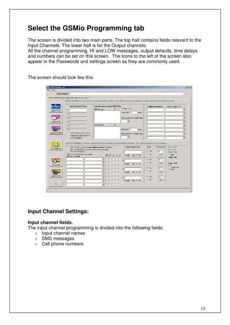
Select the GSMio Programming tab The screen is divided into two main parts. The top half contains fields relevant to the Input Channels. The lower half is for the Output channels. All the channel programming, HI and LOW messages, output defaults, time delays and numbers can be set on this screen. The Icons to the left of the screen also appear in the Passwords and settings screen as they are commonly used. The screen should look like this.
Input Channel Settings: Input channel fields. The input channel programming is divided into the following fields.
o Input channel names o SMS messages o Cell phone numbers
16
SMS Messages There are two message fields for each input channel. If channel 1 is selected then the displayed messages will apply to that channel.
Copy CH1 In many applications the same users that receive messages for Input 1 also receive the messages for the other Inputs. If this is the case then clicking the Copy CH 1 icon will result in the numbers that are programmed into Input CH 1 will be copied and pasted into the input channels 2 etc. This saves the time it would take to type these numbers in manually. (Please note that if you change numbers in the input channel
after clicking copy these new changes will not be copied until
you click copy again.)
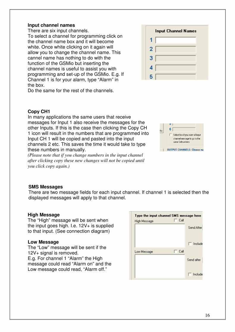
Input channel names There are six input channels. To select a channel for programming click on the channel name box and it will become white. Once white clicking on it again will allow you to change the channel name. This cannel name has nothing to do with the function of the GSMio but inserting the channel names is useful to assist you with programming and set-up of the GSMio. E.g. If Channel 1 is for your alarm, type “Alarm” in the box. Do the same for the rest of the channels.
High Message The “High” message will be sent when the input goes high. I.e. 12V+ is supplied to that input. (See connection diagram) Low Message The “Low” message will be sent if the 12V+ signal is removed. E.g. For channel 1 “Alarm” the High message could read “Alarm on” and the Low message could read, “Alarm off.”
17
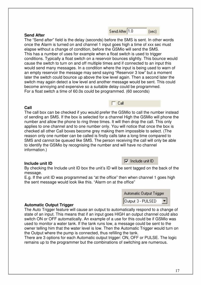
Send After The “Send after” field is the delay (seconds) before the SMS is sent. In other words once the Alarm is turned on and channel 1 input goes high a time of xxx sec must elapse without a change of condition, before the GSMio will send the SMS. This has a number of uses for example when a float switch is used to trigger conditions. Typically a float switch on a reservoir bounces slightly. This bounce would cause the switch to turn on and off multiple times and if connected to an input this would send many messages. In a condition where the input is being used to warn of an empty reservoir the message may send saying “Reservoir 3 low” but a moment later the switch could bounce up above the low level again. Then a second later the switch may again detect a low level and another message would be sent. This could become annoying and expensive so a suitable delay could be programmed. For a float switch a time of 60.0s could be programmed. (60 seconds)
Call The call box can be checked if you would prefer the GSMio to call the number instead of sending an SMS. If the box is selected for a channel High the GSMio will phone the number and allow the phone to ring three times. It will then drop the call. This only applies to one channel and to one number only. You will notice that once the box is checked all other Call boxes become grey making them impossible to select. (The reason only one number can be called is firstly calls take a long time compared to SMS and cannot be queued like SMS. The person receiving the call will only be able to identify the GSMio by recognising the number and will have no channel information.)
Include unit ID By checking the Include unit ID box the unit’s ID will be sent tagged on the back of the message. E.g. If the unit ID was programmed as “at the office” then when channel 1 goes high the sent message would look like this. “Alarm on at the office”
Automatic Output Trigger The Auto Trigger feature will cause an output to automatically respond to a change of state of an input. This means that if an input goes HIGH an output channel could also switch ON or OFF automatically. An example of a use for this could be if GSMio was used to monitor a water tank. If the tank runs low, a message could be sent to the owner telling him that the water level is low. Then the Automatic Trigger would turn on the Output where the pump is connected, thus refilling the tank. There are 3 options for each Automatic output trigger: ON, OFF or PULSE. The logic remains up to the programmer but the combinations of switching are numerous.
18
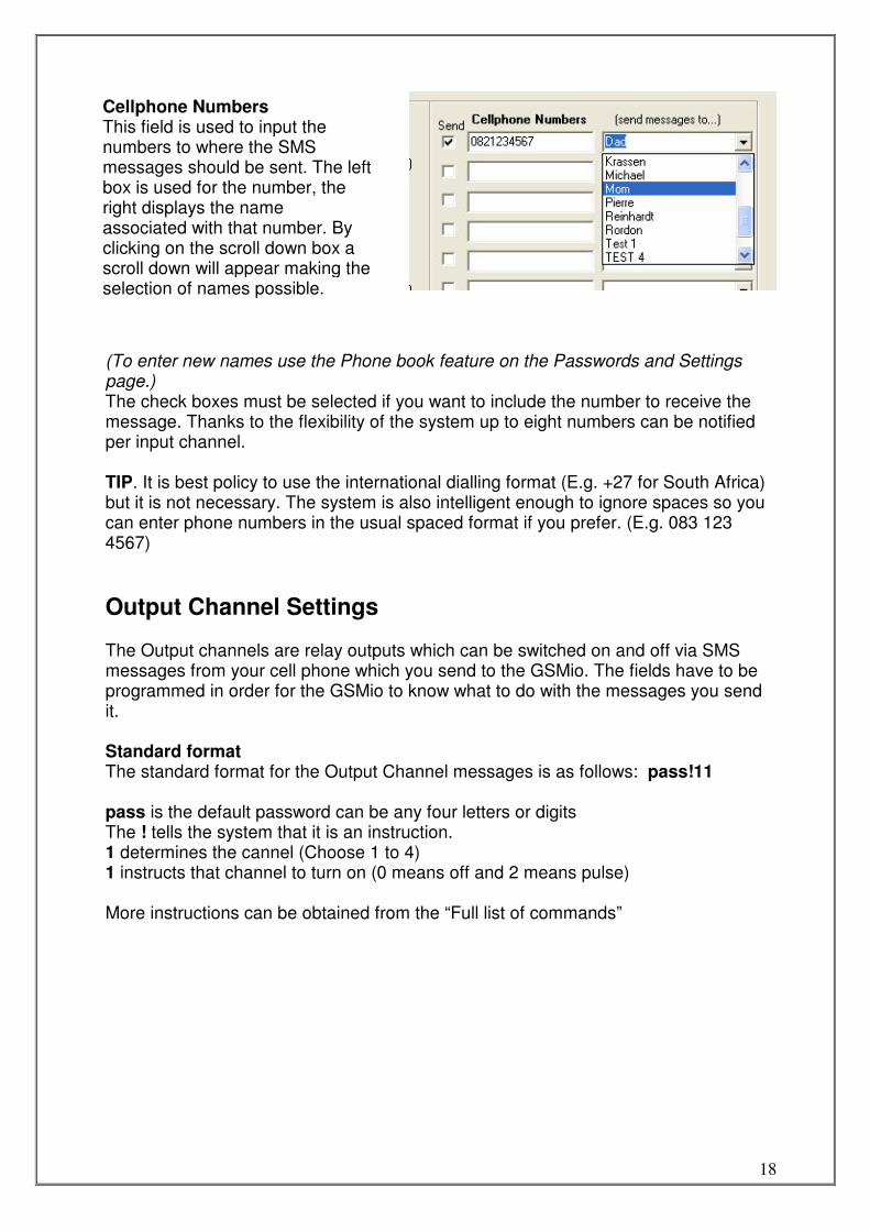
(To enter new names use the Phone book feature on the Passwords and Settings page.) The check boxes must be selected if you want to include the number to receive the message. Thanks to the flexibility of the system up to eight numbers can be notified per input channel. TIP. It is best policy to use the international dialling format (E.g. +27 for South Africa) but it is not necessary. The system is also intelligent enough to ignore spaces so you can enter phone numbers in the usual spaced format if you prefer. (E.g. 083 123 4567)
Output Channel Settings The Output channels are relay outputs which can be switched on and off via SMS messages from your cell phone which you send to the GSMio. The fields have to be programmed in order for the GSMio to know what to do with the messages you send it. Standard format The standard format for the Output Channel messages is as follows: pass!11 pass is the default password can be any four letters or digits The ! tells the system that it is an instruction. 1 determines the cannel (Choose 1 to 4) 1 instructs that channel to turn on (0 means off and 2 means pulse) More instructions can be obtained from the “Full list of commands”
Cellphone Numbers This field is used to input the numbers to where the SMS messages should be sent. The left box is used for the number, the right displays the name associated with that number. By clicking on the scroll down box a scroll down will appear making the selection of names possible.
19
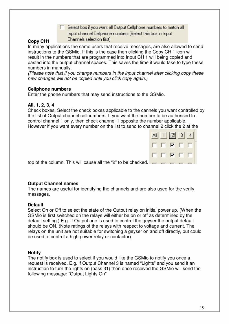
Copy CH1 In many applications the same users that receive messages, are also allowed to send instructions to the GSMio. If this is the case then clicking the Copy CH 1 icon will result in the numbers that are programmed into Input CH 1 will being copied and pasted into the output channel spaces. This saves the time it would take to type these numbers in manually. (Please note that if you change numbers in the input channel after clicking copy these new changes will not be copied until you click copy again.) Cellphone numbers Enter the phone numbers that may send instructions to the GSMio. All, 1, 2, 3, 4 Check boxes. Select the check boxes applicable to the cannels you want controlled by the list of Output channel cellnumbers. If you want the number to be authorised to control channel 1 only, then check channel 1 opposite the number applicable. However if you want every number on the list to send to channel 2 click the 2 at the
top of the column. This will cause all the “2” to be checked. Output Channel names The names are useful for identifying the channels and are also used for the verify messages. Default Select On or Off to select the state of the Output relay on initial power up. (When the GSMio is first switched on the relays will either be on or off as determined by the default setting.) E.g. If Output one is used to control the geyser the output default should be ON. (Note ratings of the relays with respect to voltage and current. The relays on the unit are not suitable for switching a geyser on and off directly, but could be used to control a high power relay or contactor) Notify The notify box is used to select if you would like the GSMio to notify you once a request is received. E.g. if Output Channel 3 is named “Lights” and you send it an instruction to turn the lights on (pass!31) then once received the GSMio will send the following message: “Output Lights On”
20
Pulse length This field is used to set how long the relay will pulse for. The pulse is a change of state and is triggered by sending a 2 to the GSMio. If the Output relay is Off then it will be switched On for the length of time determined by the Pulse length, before returning to the Off state. The time can be anything from 0.1 seconds to 999.9 seconds. (Accuracy not precise) Allow dropped call Only channel 1 can allow the dropped call feature. Once the box is checked Channel 1 can then be controlled by a dropped (missed) call. If the GSMio receives a call from an authorised number and the call is dropped before three rings the Output will be triggered. Change state If the Change state box is checked the Channel 1 relay will change state. If it is On and a dropped call is received it will turn Off. Pulse If this box is checked then a dropped call will cause the Channel 1 relay to be pulsed. This pulse length and state will be determined by the Default and Length parameters for Channel 1.
Where to get 12V?
Although the GSMio operates from anything between 8V DC and 24V DC, this manual often suggests 12V. The reason for this that 12V DC is readily available and most homes will have 12V available in one of the following places. Car battery Almost all cars operate on 12V. A cable can be made up from the cigarette lighter socket to power the GSMio. Home alarm All home alarm systems operate on a 12V DC battery as back-up and will thus also have a 12V charging circuit. The GSMio has been designed to work with alarm systems so the power from an alarm control panel is ideal. Separate plug in power supply Many of the small plug in wall transformers (Chargers) can supply 12V DC. Even if it is not a 12V supply it will probably work if is 9V or above and can deliver a current of 300mA or more. Provided the supply is DC.
What is a relay A relay is an electronic switch. In many cases it can replace a normal switch, such as a light switch in your home. Relays usually consist of a plastic body with a number of electrical contacts beneath it. These contacts are divided into two sections; 1 the actuating coil, and 2 the switch contacts.
21
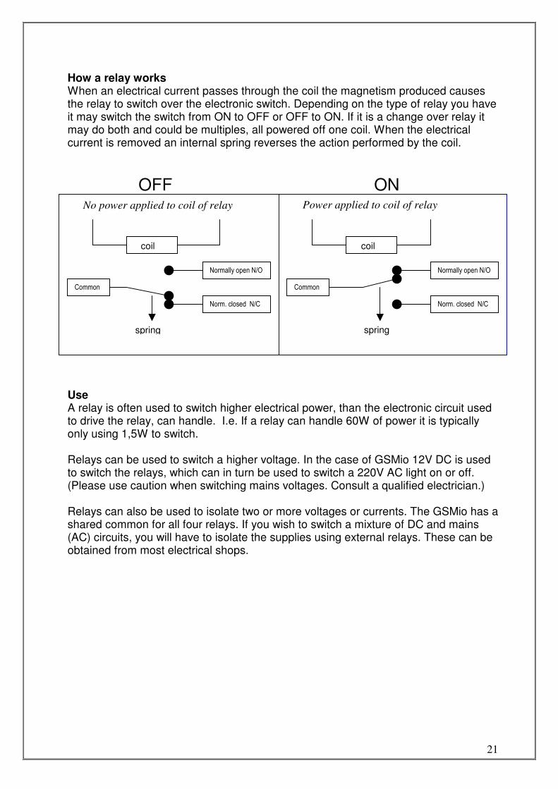
How a relay works When an electrical current passes through the coil the magnetism produced causes the relay to switch over the electronic switch. Depending on the type of relay you have it may switch the switch from ON to OFF or OFF to ON. If it is a change over relay it may do both and could be multiples, all powered off one coil. When the electrical current is removed an internal spring reverses the action performed by the coil.
OFF ON
Use A relay is often used to switch higher electrical power, than the electronic circuit used to drive the relay, can handle. I.e. If a relay can handle 60W of power it is typically only using 1,5W to switch. Relays can be used to switch a higher voltage. In the case of GSMio 12V DC is used to switch the relays, which can in turn be used to switch a 220V AC light on or off. (Please use caution when switching mains voltages. Consult a qualified electrician.) Relays can also be used to isolate two or more voltages or currents. The GSMio has a shared common for all four relays. If you wish to switch a mixture of DC and mains (AC) circuits, you will have to isolate the supplies using external relays. These can be obtained from most electrical shops.
No power applied to coil of relay
coil
Common
Normally open N/O
Norm. closed N/C
Power applied to coil of relay
spring
coil
Normally open N/O
Norm. closed N/C
Common
spring
22
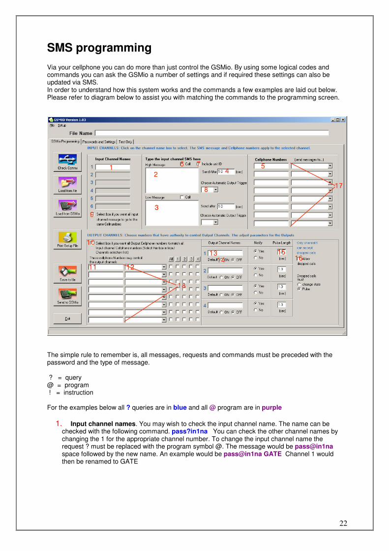
SMS programming Via your cellphone you can do more than just control the GSMio. By using some logical codes and commands you can ask the GSMio a number of settings and if required these settings can also be updated via SMS. In order to understand how this system works and the commands a few examples are laid out below. Please refer to diagram below to assist you with matching the commands to the programming screen.
The simple rule to remember is, all messages, requests and commands must be preceded with the password and the type of message. ? = query @ = program ! = instruction For the examples below all ? queries are in blue and all @ program are in purple
1. Input channel names. You may wish to check the input channel name. The name can be checked with the following command. pass?in1na You can check the other channel names by changing the 1 for the appropriate channel number. To change the input channel name the request ? must be replaced with the program symbol @. The message would be pass@in1na space followed by the new name. An example would be pass@in1na GATE Channel 1 would then be renamed to GATE
23
2. High message. The high message can be checked with the command pass?in1smshigh. The message can be changed with the command pass@in1smshigh followed by a space and the new high message. An example would be pass@in1smshigh The gate is now closed. If other channels are to be programmed then substitute the 1 with a 2, 3, 4, 5 or 6.
3. Low message. Same as High message but replace low with high. Eg pass?in1smslow
4. Send delay. The send delay for the high message can be checked by pass?in1dlhigh It cannot be adjusted via SMS
5. Send to Cell numbers. You may want to change or delete the cell numbers for certain channels. To check a particular number pass?in1num1 will respond with the number programmed into that position. If you would like to check the second number on ch2 the message would be pass?ch2num2 The numbers can all be checked at once. See 22 below for details. To change a particular number (for eg channel 3 number 6) the command would be pass@ch3num6 0834422733 This would delete the previous number and insert the new one.
6. Call. To check if the call flag is checked (ticked) pass?in1flags The unit will answer back with the condition of the flags. These flags refer to missed calling instead of sending a message for a change of condition of the input. (1 indicates yes and 0 means no.) An example answer would look like this: Input 1 flags: missed call high flag=1 unit ID high flag=0 missed call low flag=0 unit ID low flag=1 This means that the missed call is switched on of a high message and off for the low message. For a description on the unit ID flags see 8 below.
7. Unit ID flag. To check if the send unit ID flag is checked (ticked) pass?in1flags The unit will answer back with the condition of the flags. The flags refer to unit ID sending. If the answer =1 then the unit ID will be sent. If =0 then it will not be sent.
8. Automatic Output trigger (can’t be set by sms at this time)
9. Not active yet
10. Not active yet
11. Output number. This is the list of numbers that have rights to control an output. The first output number can be checked by pass?opnum1 This number can be changed by sending pass@opnum1 then a space and the new number. The old number will be deleted. An example would be pass@opnum1 0834422733 This would result in 0834422733 being able to control the outputs.
12. N/A
13. Output channel name. This is the name of the channel and is included in the message if programmed. Eg Output 1: ALARM is now on. If you would like to check the name of the output channel pass?opname1 If you would like to change the name, pass@opname1 followed by a space and the new name. The old name will be deleted. If you would like to change it from ALARM to GEYSER type pass@opname2 GEYSER and send it to the GSMio.
14. Default On / Off. In order to check if the default setting for the relay is on or off send pass?cond1 The unit will reply with the default relay setting =1 or =0 jwygfqurfxqiur gifuqrg xfiuqrixfqiurhfxiuqh rxiuqfx
15. Pulse length. This can be checked with pass?cond2 and the answer will include information relative to the pulse length, relay defaults and the notify as well.
16. Not available yet.
24
17. All input numbers. All the numbers that will receive messages for a particular input channel can be queried at once, but obviously not changed at once. By sending pass?in1numbers the unit will answer with the list of numbers. For other channels simply change the 1 for the number of the appropriate channel. For instructions on changing these numbers see 5 above.
18. All output numbers. All the numbers which have rights to control an output channel can be queried at once pass?opnumbers They have to changed individually though. See 13 above
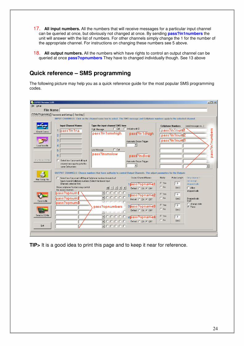
Quick reference – SMS programming The following picture may help you as a quick reference guide for the most popular SMS programming codes.
TIP> It is a good idea to print this page and to keep it near for reference.
25
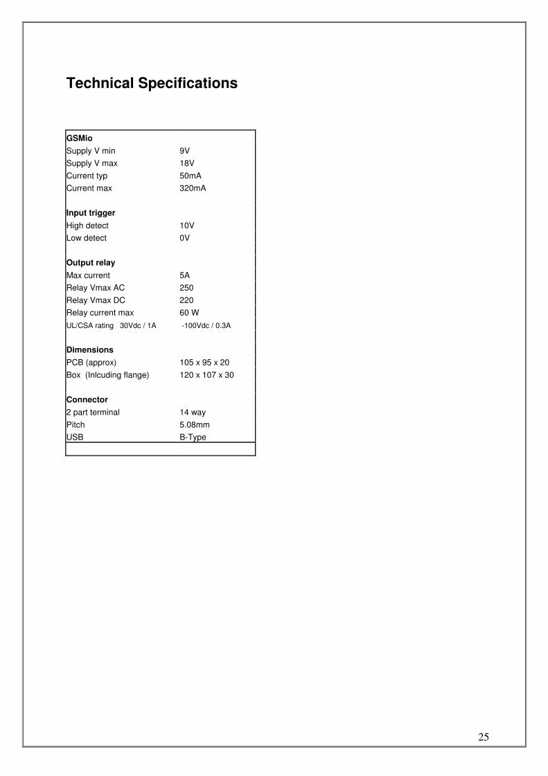
Technical Specifications
GSMio
Supply V min 9V
Supply V max 18V
Current typ 50mA
Current max 320mA
Input trigger
High detect 10V
Low detect 0V
Output relay
Max current 5A
Relay Vmax AC 250
Relay Vmax DC 220
Relay current max 60 W
UL/CSA rating 30Vdc / 1A -100Vdc / 0.3A
Dimensions
PCB (approx) 105 x 95 x 20
Box (Inlcuding flange) 120 x 107 x 30
Connector
2 part terminal 14 way
Pitch 5.08mm
USB B-Type
26
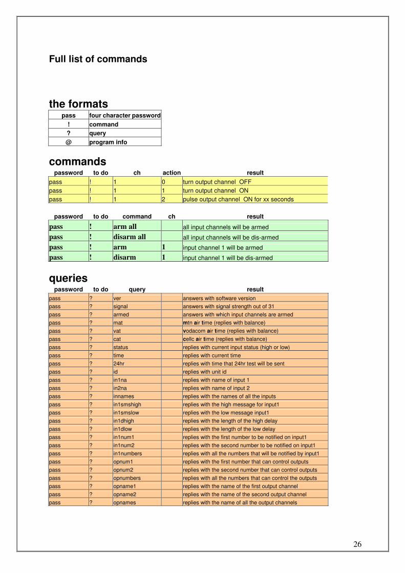
Full list of commands
the formats
pass four character password
! command
? query
@ program info
commands
password to do ch action result
pass ! 1 0 turn output channel OFF
pass ! 1 1 turn output channel ON
pass ! 1 2 pulse output channel ON for xx seconds
password to do command ch result
pass ! arm all all input channels will be armed
pass ! disarm all all input channels will be dis-armed
pass ! arm 1 input channel 1 will be armed
pass ! disarm 1 input channel 1 will be dis-armed
queries
password to do query result
pass ? ver answers with software version
pass ? signal answers with signal strength out of 31
pass ? armed answers with which input channels are armed
pass ? mat mtn air time (replies with balance)
pass ? vat vodacom air time (replies with balance)
pass ? cat cellc air time (replies with balance)
pass ? status replies with current input status (high or low)
pass ? time replies with current time
pass ? 24hr replies with time that 24hr test will be sent
pass ? id replies with unit id
pass ? in1na replies with name of input 1
pass ? in2na replies with name of input 2
pass ? innames replies with the names of all the inputs
pass ? in1smshigh replies with the high message for input1
pass ? in1smslow replies with the low message input1
pass ? in1dhigh replies with the length of the high delay
pass ? in1dlow replies with the length of the low delay
pass ? in1num1 replies with the first number to be notified on input1
pass ? in1num2 replies with the second number to be notified on input1
pass ? in1numbers replies with all the numbers that will be notified by input1
pass ? opnum1 replies with the first number that can control outputs
pass ? opnum2 replies with the second number that can control outputs
pass ? opnumbers replies with all the numbers that can control the outputs
pass ? opname1 replies with the name of the first output channel
pass ? opname2 replies with the name of the second output channel
pass ? opnames replies with the name of all the output channels
27
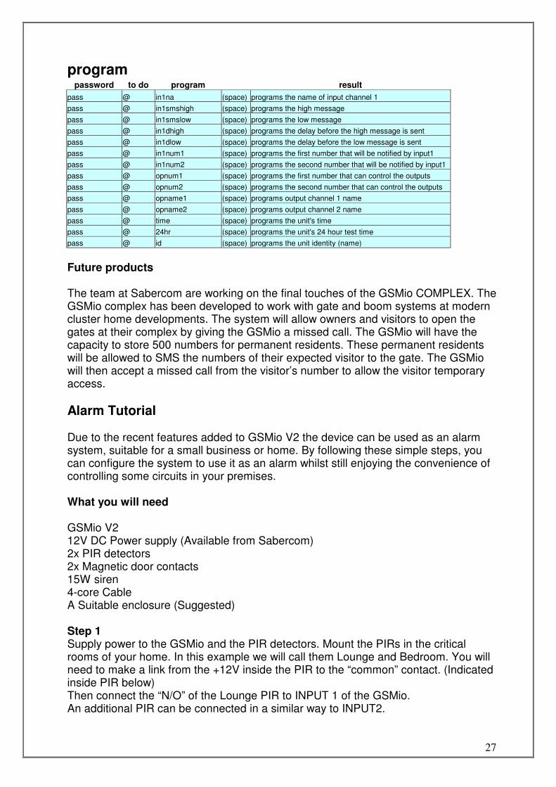
program
password to do program result
pass @ in1na (space) programs the name of input channel 1
pass @ in1smshigh (space) programs the high message
pass @ in1smslow (space) programs the low message
pass @ in1dhigh (space) programs the delay before the high message is sent
pass @ in1dlow (space) programs the delay before the low message is sent
pass @ in1num1 (space) programs the first number that will be notified by input1
pass @ in1num2 (space) programs the second number that will be notified by input1
pass @ opnum1 (space) programs the first number that can control the outputs
pass @ opnum2 (space) programs the second number that can control the outputs
pass @ opname1 (space) programs output channel 1 name
pass @ opname2 (space) programs output channel 2 name
pass @ time (space) programs the unit's time
pass @ 24hr (space) programs the unit's 24 hour test time
pass @ id (space) programs the unit identity (name)
Future products The team at Sabercom are working on the final touches of the GSMio COMPLEX. The GSMio complex has been developed to work with gate and boom systems at modern cluster home developments. The system will allow owners and visitors to open the gates at their complex by giving the GSMio a missed call. The GSMio will have the capacity to store 500 numbers for permanent residents. These permanent residents will be allowed to SMS the numbers of their expected visitor to the gate. The GSMio will then accept a missed call from the visitor’s number to allow the visitor temporary access.
Alarm Tutorial Due to the recent features added to GSMio V2 the device can be used as an alarm system, suitable for a small business or home. By following these simple steps, you can configure the system to use it as an alarm whilst still enjoying the convenience of controlling some circuits in your premises. What you will need GSMio V2 12V DC Power supply (Available from Sabercom) 2x PIR detectors 2x Magnetic door contacts 15W siren 4-core Cable A Suitable enclosure (Suggested) Step 1 Supply power to the GSMio and the PIR detectors. Mount the PIRs in the critical rooms of your home. In this example we will call them Lounge and Bedroom. You will need to make a link from the +12V inside the PIR to the “common” contact. (Indicated inside PIR below) Then connect the “N/O” of the Lounge PIR to INPUT 1 of the GSMio. An additional PIR can be connected in a similar way to INPUT2.
28
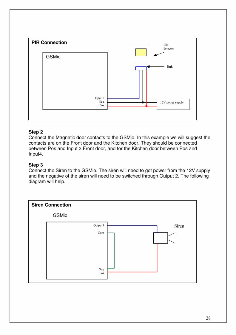
Step 2 Connect the Magnetic door contacts to the GSMio. In this example we will suggest the contacts are on the Front door and the Kitchen door. They should be connected between Pos and Input 3 Front door, and for the Kitchen door between Pos and Input4. Step 3 Connect the Siren to the GSMio. The siren will need to get power from the 12V supply and the negative of the siren will need to be switched through Output 2. The following diagram will help.
PIR Connection
12V power supply
PIR
detector
GSMio
Input 1
Neg
Pos
link
Siren Connection
Output3
Com
Neg
Pos
Siren
GSMio
29
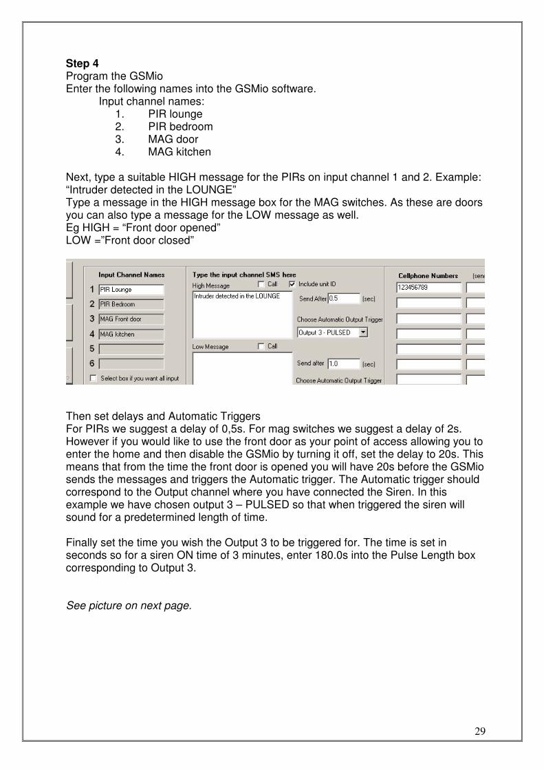
Step 4 Program the GSMio Enter the following names into the GSMio software.
Input channel names: 1. PIR lounge 2. PIR bedroom 3. MAG door 4. MAG kitchen
Next, type a suitable HIGH message for the PIRs on input channel 1 and 2. Example: “Intruder detected in the LOUNGE” Type a message in the HIGH message box for the MAG switches. As these are doors you can also type a message for the LOW message as well. Eg HIGH = “Front door opened” LOW =”Front door closed”
Then set delays and Automatic Triggers For PIRs we suggest a delay of 0,5s. For mag switches we suggest a delay of 2s. However if you would like to use the front door as your point of access allowing you to enter the home and then disable the GSMio by turning it off, set the delay to 20s. This means that from the time the front door is opened you will have 20s before the GSMio sends the messages and triggers the Automatic trigger. The Automatic trigger should correspond to the Output channel where you have connected the Siren. In this example we have chosen output 3 – PULSED so that when triggered the siren will sound for a predetermined length of time. Finally set the time you wish the Output 3 to be triggered for. The time is set in seconds so for a siren ON time of 3 minutes, enter 180.0s into the Pulse Length box corresponding to Output 3. See picture on next page.
30
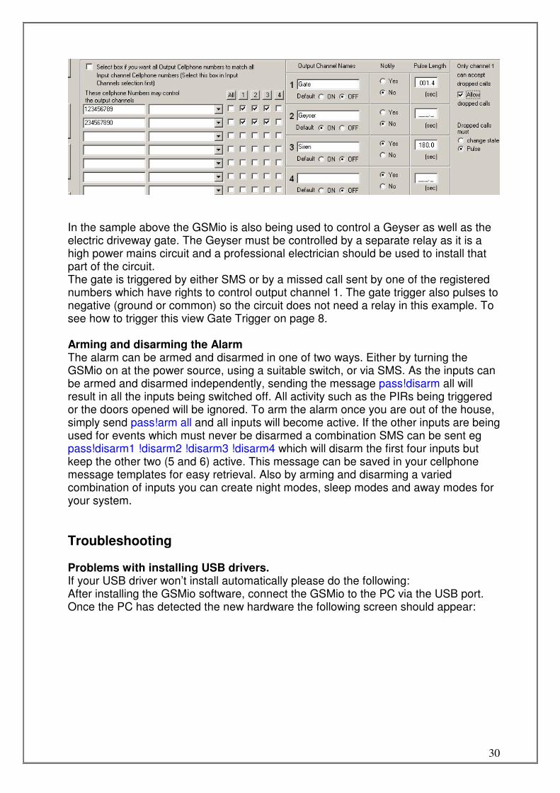
In the sample above the GSMio is also being used to control a Geyser as well as the electric driveway gate. The Geyser must be controlled by a separate relay as it is a high power mains circuit and a professional electrician should be used to install that part of the circuit. The gate is triggered by either SMS or by a missed call sent by one of the registered numbers which have rights to control output channel 1. The gate trigger also pulses to negative (ground or common) so the circuit does not need a relay in this example. To see how to trigger this view Gate Trigger on page 8. Arming and disarming the Alarm The alarm can be armed and disarmed in one of two ways. Either by turning the GSMio on at the power source, using a suitable switch, or via SMS. As the inputs can be armed and disarmed independently, sending the message pass!disarm all will result in all the inputs being switched off. All activity such as the PIRs being triggered or the doors opened will be ignored. To arm the alarm once you are out of the house, simply send pass!arm all and all inputs will become active. If the other inputs are being used for events which must never be disarmed a combination SMS can be sent eg pass!disarm1 !disarm2 !disarm3 !disarm4 which will disarm the first four inputs but keep the other two (5 and 6) active. This message can be saved in your cellphone message templates for easy retrieval. Also by arming and disarming a varied combination of inputs you can create night modes, sleep modes and away modes for your system.
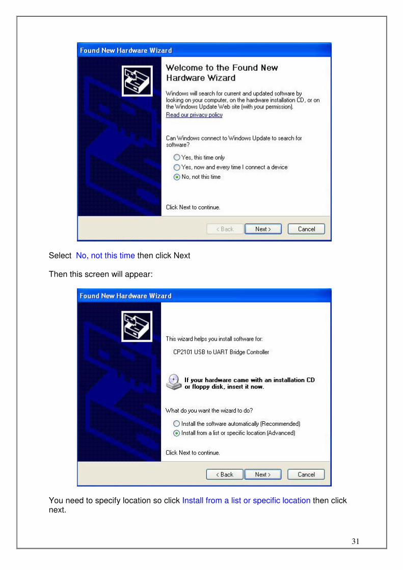
Troubleshooting Problems with installing USB drivers. If your USB driver won’t install automatically please do the following: After installing the GSMio software, connect the GSMio to the PC via the USB port. Once the PC has detected the new hardware the following screen should appear:
31
Select No, not this time then click Next Then this screen will appear:
You need to specify location so click Install from a list or specific location then click next.
32
Then this screen will appear:
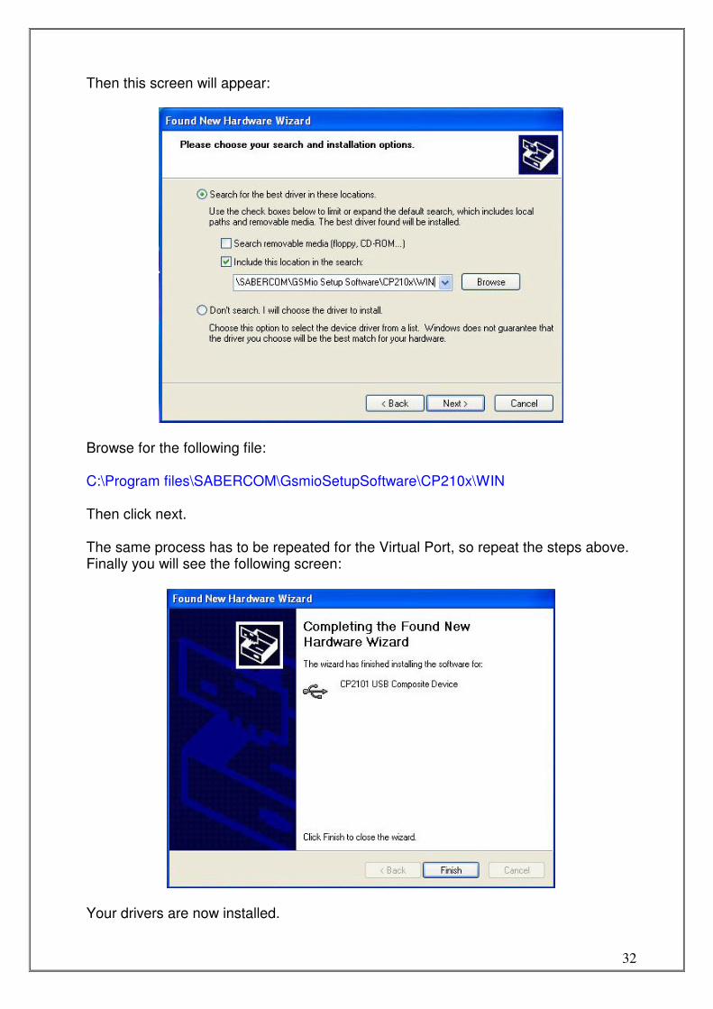
Browse for the following file: C:\Program files\SABERCOM\GsmioSetupSoftware\CP210x\WIN Then click next. The same process has to be repeated for the Virtual Port, so repeat the steps above. Finally you will see the following screen:
Your drivers are now installed.

33
Support
For support please visit www.sabercom.co.za New information is available there as well as the technical support numbers and emails.