Embed Size (px)
Citation preview
User ManualSMC Dialog Plus
Controller
Bulletin 150
1
1 1
2 1
1 2
2 2
1 3
2 3
1 4
2 4
1 5
2 5
1 6
2 6
1 7
2 7
1 8
2 8
1 9
2 9
2 0
3 0
3 5
Please Read! This manual is intended to guide qualified personnel in the installation and operation of this product.
Because of the variety of uses for this equipment and because of the differences between this solid-state equipment and electromechanical equipment, the user of and those responsible for applying this equipment must satisfy themselves as to the acceptability of each application and use of the equipment. In no event will Allen-Bradley Company, Inc. be responsible or liable for indirect or consequential damages resulting from the use or application of this equipment.
The illustrations shown in this manual are intended solely to illustrate the text of this manual. Because of the many variables and requirements associated with any particular installation, the Allen-Bradley Company, Inc. cannot assume responsibility or liability for actual use based on the illustrative uses and applications.
No patent liability is assumed by Allen-Bradley Company, Inc. with respect to use of information, circuits, or equipment described in this text.
Reproduction of the content of this manual, in whole or in part, without written permission of the Allen-Bradley Company, Inc. is prohibited.
Important User Information The information in this manual is organized in numbered chapters. Read each chapter in sequence and perform procedures when you are instructed to do so. Do not proceed to the next chapter until you have completed all procedures.
Throughout this manual attention statements make you aware of safety considerations:
Attentions help you:
• Identify a hazard
• Avoid the hazard
• Recognize the consequences
Important: Identifies information that is especially important for successful application and understanding of this product.
SMC Dialog Plus, SMB, SCANport, and Accu-Stop are trademarks of Rockwell Automation.
DeviceNet is a trademark of the Open DeviceNet Vendors Association (O.D.V.A.)
!ATTENTION: Identifies information about practices or circumstances that can lead to personal injury or death, property damage, or economic loss.
For Bulletin 150 SMC Smart Motor Controller technical support on start-up or existing installations, contact your Allen-Bradley representative. In the United States and Canada, you can also call 1-800-765-SMCS (765-7627) for assistance Monday through Friday from 8:00 a.m. to 12:00 noon and 1:00 p.m. to 4:30 p.m. (central time zone). Areas outside the United States and Canada can call 001-414-382-4650 for assistance.
Table of Contents
Chapter 1 Product Overview 1-1 Description . . . . . . . . . . . . . . . . . . . . . . . . . . . . . . . . . . . . . . . . 1-1Operation . . . . . . . . . . . . . . . . . . . . . . . . . . . . . . . . . . . . . . . . . . 1-1Starting Modes . . . . . . . . . . . . . . . . . . . . . . . . . . . . . . . . . . . . . 1-2
Soft Start . . . . . . . . . . . . . . . . . . . . . . . . . . . . . . . . . . . . . . . . 1-2Selectable Kickstart . . . . . . . . . . . . . . . . . . . . . . . . . . . . . . . . 1-3Current Limit Start. . . . . . . . . . . . . . . . . . . . . . . . . . . . . . . . . . 1-3Dual Ramp Start . . . . . . . . . . . . . . . . . . . . . . . . . . . . . . . . . . . 1-4Full Voltage Start . . . . . . . . . . . . . . . . . . . . . . . . . . . . . . . . . . 1-4
Energy Saver . . . . . . . . . . . . . . . . . . . . . . . . . . . . . . . . . . . . . . . 1-5Phase Rebalance . . . . . . . . . . . . . . . . . . . . . . . . . . . . . . . . . . . . 1-5Protection and Diagnostics . . . . . . . . . . . . . . . . . . . . . . . . . . . . . 1-5
Overload . . . . . . . . . . . . . . . . . . . . . . . . . . . . . . . . . . . . . . . . 1-5Stall Protection and Jam Detection . . . . . . . . . . . . . . . . . . . . . 1-8Open Gate . . . . . . . . . . . . . . . . . . . . . . . . . . . . . . . . . . . . . . . 1-9Line Faults . . . . . . . . . . . . . . . . . . . . . . . . . . . . . . . . . . . . . . . 1-9Underload . . . . . . . . . . . . . . . . . . . . . . . . . . . . . . . . . . . . . . . 1-9Excessive Starts/Hour . . . . . . . . . . . . . . . . . . . . . . . . . . . . . 1-10Overtemperature . . . . . . . . . . . . . . . . . . . . . . . . . . . . . . . . . 1-10
Metering . . . . . . . . . . . . . . . . . . . . . . . . . . . . . . . . . . . . . . . . . 1-10Communication . . . . . . . . . . . . . . . . . . . . . . . . . . . . . . . . . . . . 1-11Programming . . . . . . . . . . . . . . . . . . . . . . . . . . . . . . . . . . . . . . 1-11Status Indication . . . . . . . . . . . . . . . . . . . . . . . . . . . . . . . . . . . 1-11Control Options . . . . . . . . . . . . . . . . . . . . . . . . . . . . . . . . . . . . . 1-12
Soft Stop Option . . . . . . . . . . . . . . . . . . . . . . . . . . . . . . . . . . 1-12Pump Control Option . . . . . . . . . . . . . . . . . . . . . . . . . . . . . . 1-13Preset Slow Speed Option . . . . . . . . . . . . . . . . . . . . . . . . . . 1-13SMB‰ Smart Motor Braking Option . . . . . . . . . . . . . . . . . . 1-14Accu-Stop‰ Option . . . . . . . . . . . . . . . . . . . . . . . . . . . . . . . 1-15Slow Speed with Braking Option . . . . . . . . . . . . . . . . . . . . . 1-15
Chapter 2 Installation Receiving . . . . . . . . . . . . . . . . . . . . . . . . . . . . . . . . . . . . . . . . . . 2-1Unpacking . . . . . . . . . . . . . . . . . . . . . . . . . . . . . . . . . . . . . . . . . 2-1Inspecting. . . . . . . . . . . . . . . . . . . . . . . . . . . . . . . . . . . . . . . . . . 2-1Storing . . . . . . . . . . . . . . . . . . . . . . . . . . . . . . . . . . . . . . . . . . . . 2-1General Precautions . . . . . . . . . . . . . . . . . . . . . . . . . . . . . . . . . . 2-2Heat Dissipation . . . . . . . . . . . . . . . . . . . . . . . . . . . . . . . . . . . . . 2-2Enclosures . . . . . . . . . . . . . . . . . . . . . . . . . . . . . . . . . . . . . . . . . 2-2
Ventilated Enclosures . . . . . . . . . . . . . . . . . . . . . . . . . . . . . . . 2-3Non-ventilated Enclosures . . . . . . . . . . . . . . . . . . . . . . . . . . . 2-3
Mounting . . . . . . . . . . . . . . . . . . . . . . . . . . . . . . . . . . . . . . . . . . 2-4
toc–iv Table of Contents
Dimensions . . . . . . . . . . . . . . . . . . . . . . . . . . . . . . . . . . . . . . 2-4Power Factor Correction Capacitors . . . . . . . . . . . . . . . . . . . . . . 2-9Fast Acting Current-limiting Fuses . . . . . . . . . . . . . . . . . . . . . . 2-10Protective Modules . . . . . . . . . . . . . . . . . . . . . . . . . . . . . . . . . . 2-11Motor Overload Protection. . . . . . . . . . . . . . . . . . . . . . . . . . . . . 2-11
Bypass . . . . . . . . . . . . . . . . . . . . . . . . . . . . . . . . . . . . . . . . . 2-11Two-speed Motors . . . . . . . . . . . . . . . . . . . . . . . . . . . . . . . . 2-11Multi-motor Protection . . . . . . . . . . . . . . . . . . . . . . . . . . . . . 2-11
Human Interface Module . . . . . . . . . . . . . . . . . . . . . . . . . . . . . 2-12Connecting the Human Interface Module to the Controller . . . 2-13Control Enable . . . . . . . . . . . . . . . . . . . . . . . . . . . . . . . . . . . 2-13
Communication Modules . . . . . . . . . . . . . . . . . . . . . . . . . . . . . 2-16Converter Modules . . . . . . . . . . . . . . . . . . . . . . . . . . . . . . . . . . 2-16Electromagnetic Compatibility (EMC) . . . . . . . . . . . . . . . . . . . . 2-18
Enclosure . . . . . . . . . . . . . . . . . . . . . . . . . . . . . . . . . . . . . . . 2-18Grounding . . . . . . . . . . . . . . . . . . . . . . . . . . . . . . . . . . . . . . 2-18Wiring . . . . . . . . . . . . . . . . . . . . . . . . . . . . . . . . . . . . . . . . . 2-19Accessory Requirements . . . . . . . . . . . . . . . . . . . . . . . . . . . 2-19
Chapter 3 Wiring Terminal Locations . . . . . . . . . . . . . . . . . . . . . . . . . . . . . . . . . . . 3-1Power Wiring. . . . . . . . . . . . . . . . . . . . . . . . . . . . . . . . . . . . . . 3-3
Control Power . . . . . . . . . . . . . . . . . . . . . . . . . . . . . . . . . . . . . . 3-4Control Voltage . . . . . . . . . . . . . . . . . . . . . . . . . . . . . . . . . . . . 3-4Control Wiring . . . . . . . . . . . . . . . . . . . . . . . . . . . . . . . . . . . . 3-4
Fan Power. . . . . . . . . . . . . . . . . . . . . . . . . . . . . . . . . . . . . . . . . . 3-5Fan Terminations. . . . . . . . . . . . . . . . . . . . . . . . . . . . . . . . . . . 3-5
Control Terminal Designations . . . . . . . . . . . . . . . . . . . . . . . . . . 3-6Grounding Provision . . . . . . . . . . . . . . . . . . . . . . . . . . . . . . . . . . 3-6Standard Controller Wiring Diagrams . . . . . . . . . . . . . . . . . . . . . 3-7
Chapter 4 Programming Overview . . . . . . . . . . . . . . . . . . . . . . . . . . . . . . . . . . . . . . . . . . 4-1Keypad Description . . . . . . . . . . . . . . . . . . . . . . . . . . . . . . . . . . 4-1Programming Menu . . . . . . . . . . . . . . . . . . . . . . . . . . . . . . . . . . 4-1Password . . . . . . . . . . . . . . . . . . . . . . . . . . . . . . . . . . . . . . . . . . 4-5Search . . . . . . . . . . . . . . . . . . . . . . . . . . . . . . . . . . . . . . . . . . . . 4-5Parameter Management . . . . . . . . . . . . . . . . . . . . . . . . . . . . . . . 4-6
Random Access Memory (RAM). . . . . . . . . . . . . . . . . . . . . . . . 4-6Read-only Memory (ROM) . . . . . . . . . . . . . . . . . . . . . . . . . . . 4-6Electrically Erasable Programmable
Read-only Memory (EEPROM) . . . . . . . . . . . . . . . . . . . . . . 4-6Using Parameter Management . . . . . . . . . . . . . . . . . . . . . . . . 4-7
Parameter Modification . . . . . . . . . . . . . . . . . . . . . . . . . . . . . . . 4-8Soft Start. . . . . . . . . . . . . . . . . . . . . . . . . . . . . . . . . . . . . . . . . . . 4-9Current Limit Start . . . . . . . . . . . . . . . . . . . . . . . . . . . . . . . . . . . 4-9Dual Ramp Start . . . . . . . . . . . . . . . . . . . . . . . . . . . . . . . . . . . . 4-10Full Voltage Start . . . . . . . . . . . . . . . . . . . . . . . . . . . . . . . . . . . 4-10Basic Setup . . . . . . . . . . . . . . . . . . . . . . . . . . . . . . . . . . . . . . . 4-11Advanced Setup . . . . . . . . . . . . . . . . . . . . . . . . . . . . . . . . . . . . 4-12
Table of Contents toc–v
Example Settings . . . . . . . . . . . . . . . . . . . . . . . . . . . . . . . . . . . 4-13Undervoltage. . . . . . . . . . . . . . . . . . . . . . . . . . . . . . . . . . . . . 4-13Overvoltage. . . . . . . . . . . . . . . . . . . . . . . . . . . . . . . . . . . . . . 4-13Jam. . . . . . . . . . . . . . . . . . . . . . . . . . . . . . . . . . . . . . . . . . . . 4-13Underload . . . . . . . . . . . . . . . . . . . . . . . . . . . . . . . . . . . . . . . 4-13
Chapter 5 Calibration Overview . . . . . . . . . . . . . . . . . . . . . . . . . . . . . . . . . . . . . . . . . . 5-1Motor Data Entry . . . . . . . . . . . . . . . . . . . . . . . . . . . . . . . . . . . . 5-1Calibration Procedure . . . . . . . . . . . . . . . . . . . . . . . . . . . . . . . . . 5-3
Chapter 6 Metering Overview. . . . . . . . . . . . . . . . . . . . . . . . . . . . . . . . . . . . . . . . . . . 6-1Viewing Metering Data . . . . . . . . . . . . . . . . . . . . . . . . . . . . . . . . 6-1
Chapter 7 Options Overview . . . . . . . . . . . . . . . . . . . . . . . . . . . . . . . . . . . . . . . . . . 7-1Human Interface Module . . . . . . . . . . . . . . . . . . . . . . . . . . . . . . 7-1Programming Parameters . . . . . . . . . . . . . . . . . . . . . . . . . . . . . 7-3Control Wiring for SCANport Control . . . . . . . . . . . . . . . . . . . . . . 7-5Soft Stop, Pump Control, andSMB Smart Motor Braking Options . . . . . . . . . . . . . . . . . . . . . . . 7-6Soft Stop Option . . . . . . . . . . . . . . . . . . . . . . . . . . . . . . . . . . . . 7-12Pump Control Option . . . . . . . . . . . . . . . . . . . . . . . . . . . . . . . . . 7-13SMB Smart Motor Braking Option . . . . . . . . . . . . . . . . . . . . . . . 7-14Preset Slow Speed and Accu-Stop Options . . . . . . . . . . . . . . . . 7-15Preset Slow Speed Option . . . . . . . . . . . . . . . . . . . . . . . . . . . . 7-20Accu-Stop Option . . . . . . . . . . . . . . . . . . . . . . . . . . . . . . . . . . . 7-21Slow Speed with Braking Option . . . . . . . . . . . . . . . . . . . . . . . . 7-22
Chapter 8 Serial Communications Overview . . . . . . . . . . . . . . . . . . . . . . . . . . . . . . . . . . . . . . . . . . 8-1Logic Control Data . . . . . . . . . . . . . . . . . . . . . . . . . . . . . . . . . . . 8-1Control Wiring . . . . . . . . . . . . . . . . . . . . . . . . . . . . . . . . . . . . . . 8-1Control Enable . . . . . . . . . . . . . . . . . . . . . . . . . . . . . . . . . . . . . . 8-2SMC Status Data . . . . . . . . . . . . . . . . . . . . . . . . . . . . . . . . . . . . 8-3Reference/Feedback . . . . . . . . . . . . . . . . . . . . . . . . . . . . . . . . . 8-3Parameter Listing . . . . . . . . . . . . . . . . . . . . . . . . . . . . . . . . . . . . 8-3Scale Factor Conversion . . . . . . . . . . . . . . . . . . . . . . . . . . . . . . . 8-3Display Unit Equivalents . . . . . . . . . . . . . . . . . . . . . . . . . . . . . . . 8-4Datalinks . . . . . . . . . . . . . . . . . . . . . . . . . . . . . . . . . . . . . . . . . . 8-4Interfacing . . . . . . . . . . . . . . . . . . . . . . . . . . . . . . . . . . . . . . . . . 8-4Processing Time . . . . . . . . . . . . . . . . . . . . . . . . . . . . . . . . . . . . . 8-4Remote I/O Examples . . . . . . . . . . . . . . . . . . . . . . . . . . . . . . . . . 8-5
Example #1 – SLC 500 Controller without Block Transfer . . . . 8-51203-GD1 Communication Module Switch Settings . . . . . . . . 8-6G File Configuration . . . . . . . . . . . . . . . . . . . . . . . . . . . . . . . . . 8-7I/O Addressing . . . . . . . . . . . . . . . . . . . . . . . . . . . . . . . . . . . . 8-7Example #1 - Ladder Logic Program . . . . . . . . . . . . . . . . . . . . 8-9Example #2 - SLC 500 Controller with Block Transfer . . . . . . 8-101203-GD1 Communication Module Switch Settings . . . . . . . 8-10Example #2 – Ladder Logic Program . . . . . . . . . . . . . . . . . . 8-15
toc–vi Table of Contents
Example #3 – PLC 5/20, 5/40, 5/60, and 5/80 . . . . . . . . . . . 8-181203-GD1 Communication Module Switch Settings . . . . . . . 8-19I/O Addressing . . . . . . . . . . . . . . . . . . . . . . . . . . . . . . . . . . . 8-19Block Transfer Instructions . . . . . . . . . . . . . . . . . . . . . . . . . . 8-21Block Transfer Datafiles . . . . . . . . . . . . . . . . . . . . . . . . . . . . 8-22Example #3 Ladder Logic Program . . . . . . . . . . . . . . . . . . . . 8-23
DeviceNet Examples . . . . . . . . . . . . . . . . . . . . . . . . . . . . . . . . . 8-24Example #1 SLC Controller with Explicit Messaging. . . . . . . . 8-241203-GK5 Communication Module Switch Settings . . . . . . . . 8-24Example Information . . . . . . . . . . . . . . . . . . . . . . . . . . . . . . . 8-25Switch Settings . . . . . . . . . . . . . . . . . . . . . . . . . . . . . . . . . . . 8-25I/O Mapping . . . . . . . . . . . . . . . . . . . . . . . . . . . . . . . . . . . . . 8-25SMC Dialog Plus Controller Logic Command Addresses . . . . . 8-29Explicit Messaging. . . . . . . . . . . . . . . . . . . . . . . . . . . . . . . . . 8-29Explicit Message Request (Get Attribute Multiple) . . . . . . . . . 8-29Explicit Message Response (Get Attribute Multiple) . . . . . . . . 8-29Examples . . . . . . . . . . . . . . . . . . . . . . . . . . . . . . . . . . . . . . . 8-30Sequence of Events . . . . . . . . . . . . . . . . . . . . . . . . . . . . . . . . 8-31Setting up the Data File . . . . . . . . . . . . . . . . . . . . . . . . . . . . . 8-31Example Ladder Logic Program . . . . . . . . . . . . . . . . . . . . . . . 8-32
Chapter 9 Diagnostics Overview . . . . . . . . . . . . . . . . . . . . . . . . . . . . . . . . . . . . . . . . . . 9-1Protection Programming . . . . . . . . . . . . . . . . . . . . . . . . . . . . . 9-1
Fault Display . . . . . . . . . . . . . . . . . . . . . . . . . . . . . . . . . . . . . . . 9-1Clear Fault . . . . . . . . . . . . . . . . . . . . . . . . . . . . . . . . . . . . . . . . . 9-1Fault Buffer . . . . . . . . . . . . . . . . . . . . . . . . . . . . . . . . . . . . . . . . . 9-2
Fault Codes . . . . . . . . . . . . . . . . . . . . . . . . . . . . . . . . . . . . . . 9-2Fault Auxiliary Contact . . . . . . . . . . . . . . . . . . . . . . . . . . . . . . . . 9-2Fault Definitions . . . . . . . . . . . . . . . . . . . . . . . . . . . . . . . . . . . . . 9-3
Power Loss . . . . . . . . . . . . . . . . . . . . . . . . . . . . . . . . . . . . . . . 9-3Line Fault . . . . . . . . . . . . . . . . . . . . . . . . . . . . . . . . . . . . . . . . 9-3
Phase Reversal . . . . . . . . . . . . . . . . . . . . . . . . . . . . . . . . . . . . . . 9-3Overvoltage and Undervoltage Protection . . . . . . . . . . . . . . . . 9-3Voltage Unbalance. . . . . . . . . . . . . . . . . . . . . . . . . . . . . . . . . . 9-4Stall Protection . . . . . . . . . . . . . . . . . . . . . . . . . . . . . . . . . . . . 9-4Jam Detection . . . . . . . . . . . . . . . . . . . . . . . . . . . . . . . . . . . . . 9-4Overload Protection . . . . . . . . . . . . . . . . . . . . . . . . . . . . . . . . . 9-4Underload . . . . . . . . . . . . . . . . . . . . . . . . . . . . . . . . . . . . . . . . 9-4Open Gate . . . . . . . . . . . . . . . . . . . . . . . . . . . . . . . . . . . . . . . . 9-5Excess Starts/Hour . . . . . . . . . . . . . . . . . . . . . . . . . . . . . . . . . 9-5Controller Temp. . . . . . . . . . . . . . . . . . . . . . . . . . . . . . . . . . . . 9-5Comm Fault . . . . . . . . . . . . . . . . . . . . . . . . . . . . . . . . . . . . . . 9-5
Chapter 10 Troubleshooting Introduction. . . . . . . . . . . . . . . . . . . . . . . . . . . . . . . . . . . . . . . . 10-1Control Module Removal . . . . . . . . . . . . . . . . . . . . . . . . . . . . . . 10-6
24–135 Amp . . . . . . . . . . . . . . . . . . . . . . . . . . . . . . . . . . . . 10-7
Table of Contents toc–vii
180–360 Amp . . . . . . . . . . . . . . . . . . . . . . . . . . . . . . . . . . . 10-8500–1000 Amp . . . . . . . . . . . . . . . . . . . . . . . . . . . . . . . . . . 10-10
Control Module Replacement . . . . . . . . . . . . . . . . . . . . . . . . . 10-11Protective Cover Removal . . . . . . . . . . . . . . . . . . . . . . . . . . . . 10-12
650–1000 Amp . . . . . . . . . . . . . . . . . . . . . . . . . . . . . . . . . 10-12MOV Fuse Replacement . . . . . . . . . . . . . . . . . . . . . . . . . . . . . 10-13
500–1000 Amp . . . . . . . . . . . . . . . . . . . . . . . . . . . . . . . . . 10-13Power Module and Interface Board Resistance Check . . . . . . 10-13
24–135 Amp . . . . . . . . . . . . . . . . . . . . . . . . . . . . . . . . . . . 10-14180-1000 Amp . . . . . . . . . . . . . . . . . . . . . . . . . . . . . . . . . . 10-23
Appendix A Specifications
Appendix B Parameter Information
Appendix C Renewal Parts
Appendix D Accessories
Figures Figure 1.1 Soft Start . . . . . . . . . . . . . . . . . . . . . . . . . . . . . . . . 1-2Figure 1.2 Selectable Kickstart . . . . . . . . . . . . . . . . . . . . . . . 1-3Figure 1.3 Current Limit Start . . . . . . . . . . . . . . . . . . . . . . . . 1-3Figure 1.4 Dual Ramp Start . . . . . . . . . . . . . . . . . . . . . . . . . . 1-4Figure 1.5 Full Voltage Start . . . . . . . . . . . . . . . . . . . . . . . . . . 1-4Figure 1.6 Overload Trip Curves . . . . . . . . . . . . . . . . . . . . . . . 1-7Figure 1.7 Restart Trip Curves after Auto Reset. . . . . . . . . . . . 1-7Figure 1.8 Stall Protection . . . . . . . . . . . . . . . . . . . . . . . . . . . 1-8Figure 1.9 Jam Detection . . . . . . . . . . . . . . . . . . . . . . . . . . . . 1-8Figure 1.10 ScanPort Location . . . . . . . . . . . . . . . . . . . . . . . . 1-11Figure 1.11 Built-in Keypad and LCD . . . . . . . . . . . . . . . . . . . 1-11Figure 1.12 Soft Stop Option . . . . . . . . . . . . . . . . . . . . . . . . . 1-12Figure 1.13 Pump Control Option . . . . . . . . . . . . . . . . . . . . . . 1-13Figure 1.14 Preset Slow Speed Option . . . . . . . . . . . . . . . . . . 1-13Figure 1.15 SMB Smart Motor Braking Option. . . . . . . . . . . . . 1-14Figure 1.16 Accu-Stop Option . . . . . . . . . . . . . . . . . . . . . . . . 1-15Figure 1.17 Slow Speed with Braking Option . . . . . . . . . . . . . 1-15Figure 2.1 Dimensions: 24, 35, and 54 Amp Controllers . . . . 2-4Figure 2.2 Dimensions: 97 and 135 Amp Controllers . . . . . . . 2-5Figure 2.3 Dimensions: 180 through 360 Amp Controllers . . . 2-6Figure 2.4 Dimensions: 500 Amp Controller . . . . . . . . . . . . . . 2-7Figure 2.5 Dimensions: 650-1000 Amp Controllers . . . . . . . . 2-8Figure 2.6 Typical Wiring Diagram for Power
Factor Correction Capacitors . . . . . . . . . . . . . . . . . 2-9Figure 2.7 SMC Dialog Plus Controller with
Human Interface Module . . . . . . . . . . . . . . . . . . . 2-13Figure 2.8 SMC Dialog Plus Controller with
Communication Module . . . . . . . . . . . . . . . . . . . . 2-16Figure 2.9 Converter Module Connection Interface . . . . . . . . 2-17
toc–viii Table of Contents
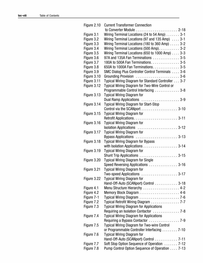
Figure 2.10 Current Transformer Connection to Converter Module . . . . . . . . . . . . . . . . . . . . . . 2-18
Figure 3.1 Wiring Terminal Locations (24 to 54 Amp) . . . . . . . 3-1Figure 3.2 Wiring Terminal Locations (97 and 135 Amp) . . . . 3-1Figure 3.3 Wiring Terminal Locations (180 to 360 Amp) . . . . . 3-2Figure 3.4 Wiring Terminal Locations (500 Amp). . . . . . . . . . . 3-2Figure 3.5 Wiring Terminal Locations (650 to 1000 Amp) . . . . 3-3FIgure 3.6 97A and 135A Fan Terminations . . . . . . . . . . . . . . 3-5Figure 3.7 180A to 500A Fan Terminations. . . . . . . . . . . . . . . 3-5Figure 3.8 650A to 1000A Fan Terminations. . . . . . . . . . . . . . 3-5Figure 3.9 SMC Dialog Plus Controller Control Terminals . . . . 3-6Figure 3.10 Grounding Provision . . . . . . . . . . . . . . . . . . . . . . . 3-6Figure 3.11 Typical Wiring Diagram for Standard Controller . . . 3-7Figure 3.12 Typical Wiring Diagram for Two-Wire Control or
Programmable Control Interfacing . . . . . . . . . . . . . 3-8Figure 3.13 Typical Wiring Diagram for
Dual Ramp Applications . . . . . . . . . . . . . . . . . . . . 3-9Figure 3.14 Typical Wiring Diagram for Start-Stop
Control via the SCANport . . . . . . . . . . . . . . . . . . . 3-10Figure 3.15 Typical Wiring Diagram for
Retrofit Applications. . . . . . . . . . . . . . . . . . . . . . . 3-11Figure 3.16 Typical Wiring Diagram for
Isolation Applications . . . . . . . . . . . . . . . . . . . . . 3-12Figure 3.17 Typical Wiring Diagram for
Bypass Applications . . . . . . . . . . . . . . . . . . . . . . 3-13Figure 3.18 Typical Wiring Diagram for Bypass
with Isolation Applications . . . . . . . . . . . . . . . . . . 3-14Figure 3.19 Typical Wiring Diagram for
Shunt Trip Applications . . . . . . . . . . . . . . . . . . . . 3-15Figure 3.20 Typical Wiring Diagram for Single
Speed Reversing Applications . . . . . . . . . . . . . . . 3-16Figure 3.21 Typical Wiring Diagram for
Two-speed Applications . . . . . . . . . . . . . . . . . . . 3-17Figure 3.22 Typical Wiring Diagram for
Hand-Off-Auto (SCANport) Control . . . . . . . . . . . . 3-18Figure 4.1 Menu Structure Hierarchy . . . . . . . . . . . . . . . . . . . 4-2Figure 4.2 Memory Block Diagram . . . . . . . . . . . . . . . . . . . . . 4-6Figure 7-1 Typical Wiring Diagram . . . . . . . . . . . . . . . . . . . . . 7-6Figure 7.2 Typical Retrofit Wiring Diagram . . . . . . . . . . . . . . . 7-7Figure 7.3 Typical Wiring Diagram for Applications
Requiring an Isolation Contactor . . . . . . . . . . . . . . 7-8Figure 7.4 Typical Wiring Diagram for Applications
Requiring a Bypass Contactor . . . . . . . . . . . . . . . . 7-9Figure 7.5 Typical Wiring Diagram for Two-wire Control
or Programmable Controller Interfacing . . . . . . . . 7-10Figure 7.6 Typical Wiring Diagram for
Hand-Off-Auto (SCANport) Control . . . . . . . . . . . . 7-11Figure 7.7 Soft Stop Option Sequence of Operation . . . . . . . 7-12Figure 7.8 Pump Control Option Sequence of Operation . . . . 7-13
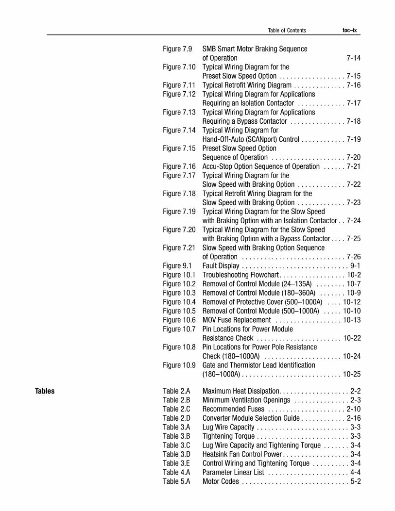
Table of Contents toc–ix
Figure 7.9 SMB Smart Motor Braking Sequence of Operation 7-14
Figure 7.10 Typical Wiring Diagram for the Preset Slow Speed Option . . . . . . . . . . . . . . . . . . 7-15
Figure 7.11 Typical Retrofit Wiring Diagram . . . . . . . . . . . . . . 7-16Figure 7.12 Typical Wiring Diagram for Applications
Requiring an Isolation Contactor . . . . . . . . . . . . . 7-17Figure 7.13 Typical Wiring Diagram for Applications
Requiring a Bypass Contactor . . . . . . . . . . . . . . . 7-18Figure 7.14 Typical Wiring Diagram for
Hand-Off-Auto (SCANport) Control . . . . . . . . . . . . 7-19Figure 7.15 Preset Slow Speed Option
Sequence of Operation . . . . . . . . . . . . . . . . . . . . 7-20Figure 7.16 Accu-Stop Option Sequence of Operation . . . . . . 7-21Figure 7.17 Typical Wiring Diagram for the
Slow Speed with Braking Option . . . . . . . . . . . . . 7-22Figure 7.18 Typical Retrofit Wiring Diagram for the
Slow Speed with Braking Option . . . . . . . . . . . . . 7-23Figure 7.19 Typical Wiring Diagram for the Slow Speed
with Braking Option with an Isolation Contactor . . 7-24Figure 7.20 Typical Wiring Diagram for the Slow Speed
with Braking Option with a Bypass Contactor . . . . 7-25Figure 7.21 Slow Speed with Braking Option Sequence
of Operation . . . . . . . . . . . . . . . . . . . . . . . . . . . . 7-26Figure 9.1 Fault Display . . . . . . . . . . . . . . . . . . . . . . . . . . . . . 9-1Figure 10.1 Troubleshooting Flowchart . . . . . . . . . . . . . . . . . . 10-2Figure 10.2 Removal of Control Module (24–135A) . . . . . . . . 10-7Figure 10.3 Removal of Control Module (180–360A) . . . . . . . 10-9Figure 10.4 Removal of Protective Cover (500–1000A) . . . . 10-12Figure 10.5 Removal of Control Module (500–1000A) . . . . . 10-10Figure 10.6 MOV Fuse Replacement . . . . . . . . . . . . . . . . . . 10-13Figure 10.7 Pin Locations for Power Module
Resistance Check . . . . . . . . . . . . . . . . . . . . . . . 10-22Figure 10.8 Pin Locations for Power Pole Resistance
Check (180–1000A) . . . . . . . . . . . . . . . . . . . . . 10-24Figure 10.9 Gate and Thermistor Lead Identification
(180–1000A) . . . . . . . . . . . . . . . . . . . . . . . . . . . 10-25
Tables Table 2.A Maximum Heat Dissipation. . . . . . . . . . . . . . . . . . . 2-2Table 2.B Minimum Ventilation Openings . . . . . . . . . . . . . . . 2-3Table 2.C Recommended Fuses . . . . . . . . . . . . . . . . . . . . . 2-10Table 2.D Converter Module Selection Guide . . . . . . . . . . . . 2-16Table 3.A Lug Wire Capacity . . . . . . . . . . . . . . . . . . . . . . . . . 3-3Table 3.B Tightening Torque . . . . . . . . . . . . . . . . . . . . . . . . . 3-3Table 3.C Lug Wire Capacity and Tightening Torque . . . . . . . 3-4Table 3.D Heatsink Fan Control Power . . . . . . . . . . . . . . . . . . 3-4Table 3.E Control Wiring and Tightening Torque . . . . . . . . . . 3-4Table 4.A Parameter Linear List . . . . . . . . . . . . . . . . . . . . . . 4-4Table 5.A Motor Codes . . . . . . . . . . . . . . . . . . . . . . . . . . . . . 5-2
toc–x Table of Contents
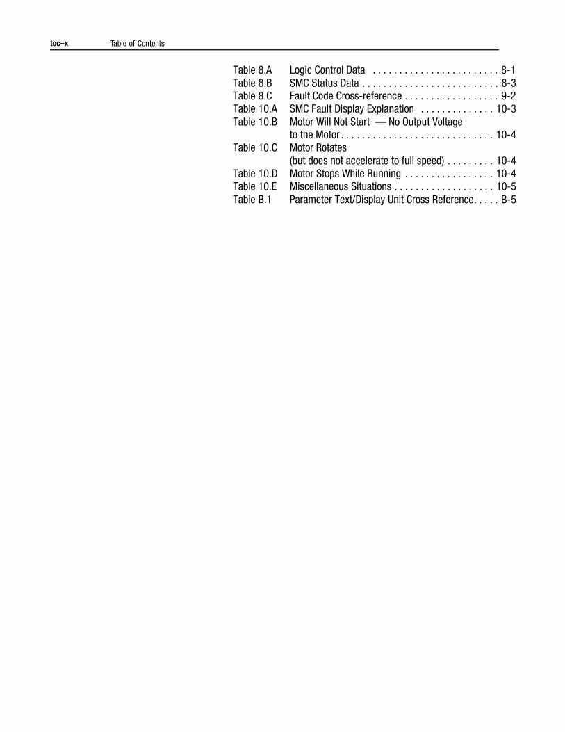
Table 8.A Logic Control Data . . . . . . . . . . . . . . . . . . . . . . . . 8-1Table 8.B SMC Status Data . . . . . . . . . . . . . . . . . . . . . . . . . . 8-3Table 8.C Fault Code Cross-reference . . . . . . . . . . . . . . . . . . 9-2Table 10.A SMC Fault Display Explanation . . . . . . . . . . . . . . 10-3Table 10.B Motor Will Not Start — No Output Voltage
to the Motor . . . . . . . . . . . . . . . . . . . . . . . . . . . . . 10-4Table 10.C Motor Rotates
(but does not accelerate to full speed) . . . . . . . . . 10-4Table 10.D Motor Stops While Running . . . . . . . . . . . . . . . . . 10-4Table 10.E Miscellaneous Situations . . . . . . . . . . . . . . . . . . . 10-5Table B.1 Parameter Text/Display Unit Cross Reference. . . . . B-5
Chapter 1
Product Overview
Description The SMC Dialog Plus controller offers a full range of starting modes as standard:
• Soft Start with Selectable Kickstart
• Current Limit Start with Selectable Kickstart
• Dual Ramp Start
• Full Voltage Start
Other features that offer further user benefit include:
• Expanded protective features
• Metering
• Communication capability
Innovative starting and stopping options provide enhanced performance:
• Soft Stop
• Pump Control
• Preset Slow Speed
• SMB™ Smart Motor Braking
• Accu-Stop
• Slow Speed with Braking
These modes, features, and options are further described in this chapter.
Operation The SMC Dialog Plus controller can operate three-phase squirrel cage motors rated 1–1000A; 200–480V AC or 200–600V AC; 50/60 Hz. Depending upon the catalog number ordered, the controller will accept a control power input of either 100–240V AC or 24V AC/DC. If the control power input option is 100–240V AC, the controller’s microprocessor will self-adjust to the input control voltage.
1-2 Product Overview
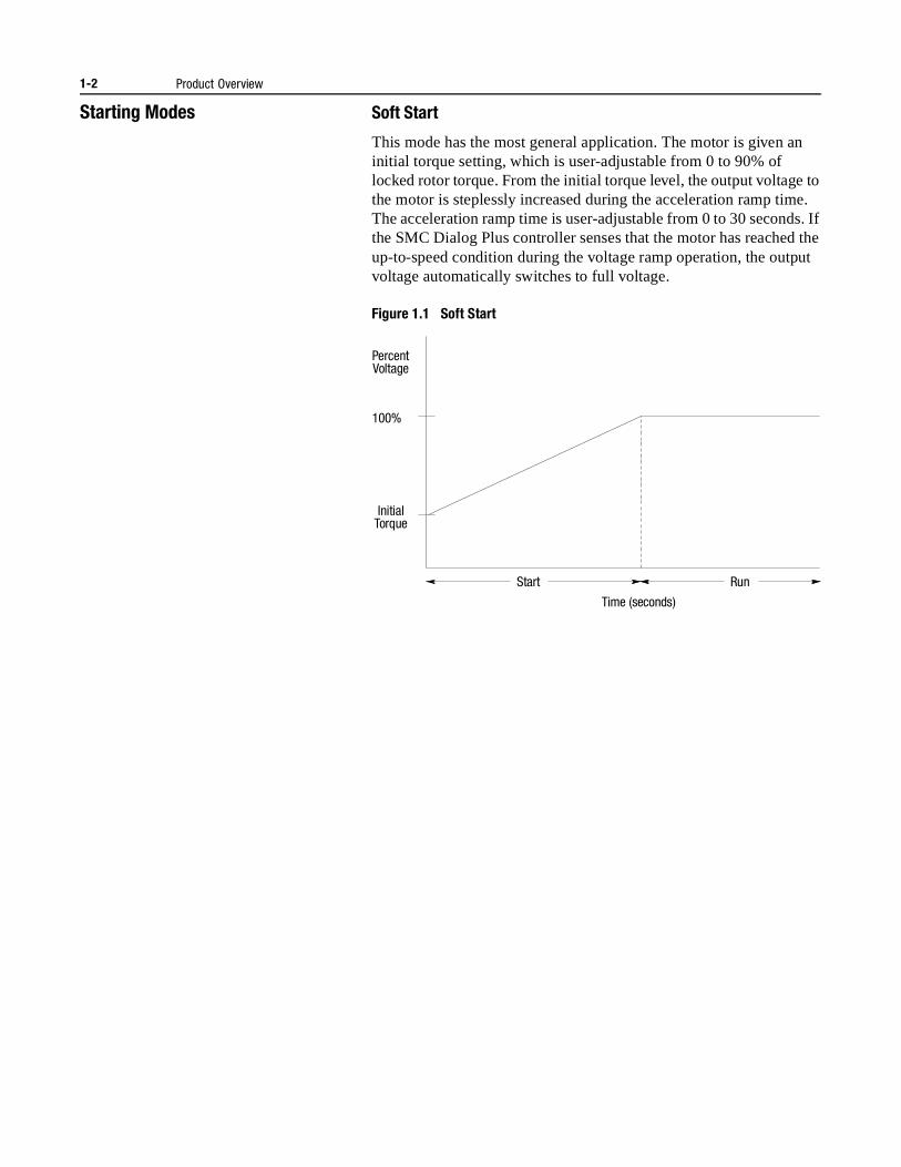
Starting Modes Soft Start
This mode has the most general application. The motor is given an initial torque setting, which is user-adjustable from 0 to 90% of locked rotor torque. From the initial torque level, the output voltage to the motor is steplessly increased during the acceleration ramp time. The acceleration ramp time is user-adjustable from 0 to 30 seconds. If the SMC Dialog Plus controller senses that the motor has reached the up-to-speed condition during the voltage ramp operation, the output voltage automatically switches to full voltage.
Figure 1.1 Soft Start
Start Run
Percent Voltage
Initial Torque
100%
Time (seconds)
Product Overview 1-3
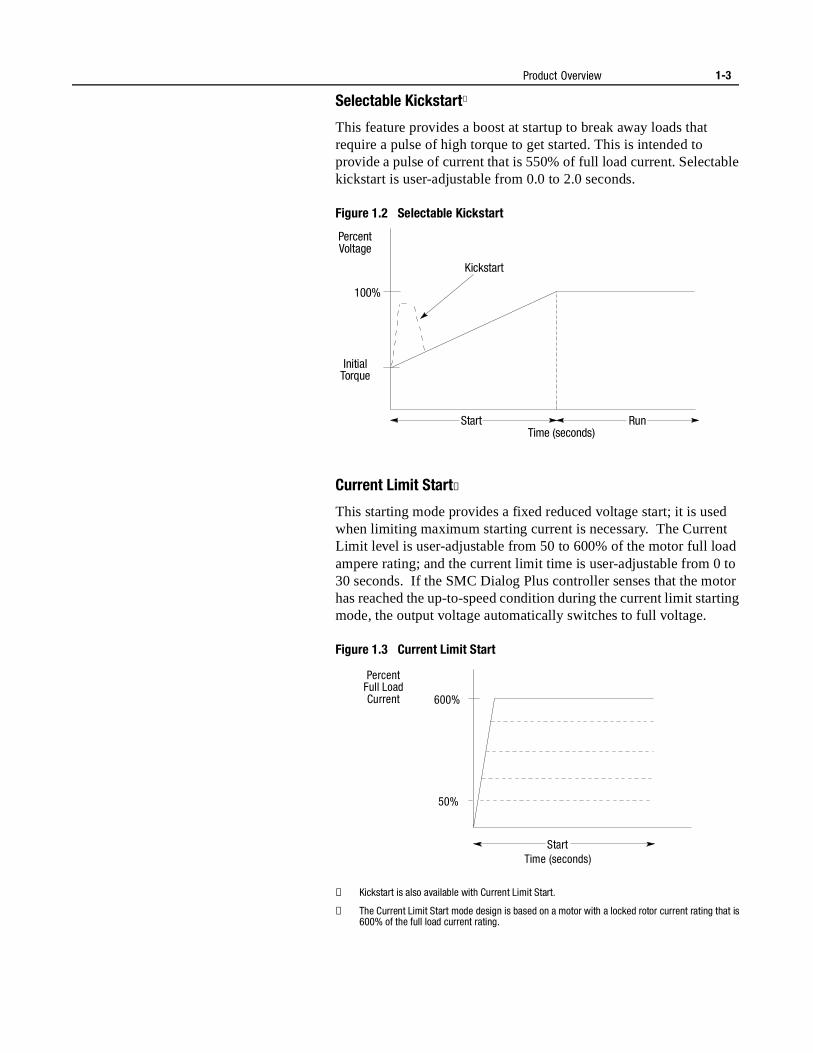
Selectable Kickstart①
This feature provides a boost at startup to break away loads that require a pulse of high torque to get started. This is intended to provide a pulse of current that is 550% of full load current. Selectable kickstart is user-adjustable from 0.0 to 2.0 seconds.
Figure 1.2 Selectable Kickstart
Current Limit Start②
This starting mode provides a fixed reduced voltage start; it is used when limiting maximum starting current is necessary. The Current Limit level is user-adjustable from 50 to 600% of the motor full load ampere rating; and the current limit time is user-adjustable from 0 to 30 seconds. If the SMC Dialog Plus controller senses that the motor has reached the up-to-speed condition during the current limit starting mode, the output voltage automatically switches to full voltage.
Figure 1.3 Current Limit Start
① Kickstart is also available with Current Limit Start.
② The Current Limit Start mode design is based on a motor with a locked rotor current rating that is 600% of the full load current rating.
Start Run
Kickstart
Initial Torque
100%
Percent Voltage
Time (seconds)
Start
600%
50%
Percent Full Load Current
Time (seconds)
1-4 Product Overview
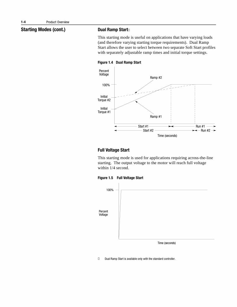
Starting Modes (cont.) Dual Ramp Start①
This starting mode is useful on applications that have varying loads (and therefore varying starting torque requirements). Dual Ramp Start allows the user to select between two separate Soft Start profiles with separately adjustable ramp times and initial torque settings.
Figure 1.4 Dual Ramp Start
Full Voltage Start
This starting mode is used for applications requiring across-the-line starting. The output voltage to the motor will reach full voltage within 1/4 second.
Figure 1.5 Full Voltage Start
① Dual Ramp Start is available only with the standard controller.
Percent Voltage
Initial Torque #1
100%
Start #1 Run #1
Ramp #2
Ramp #1
Start #2
Time (seconds)
Run #2
Initial Torque #2
100%
Percent Voltage
Time (seconds)
Product Overview 1-5
Energy Saver The Energy Saver feature is typically used in applications where the motor is lightly loaded or unloaded for extended periods of time. With the Energy Saver feature enabled, the SMC Dialog Plus controller continuously monitors motor load with its internal feedback circuitry. Because SCRs control the output voltage, motor power losses may be reduced by decreasing the motor terminal voltage.
Notes: (1) The Energy Saver feature is not available when a bypass contactor is used.
(2) When Energy Saver and Phase Rebalance are both enabled, Phase Rebalance takes precedence in operation.
Phase Rebalance With the Phase Rebalance feature enabled, the SMC Dialog Plus controller continuously monitors the incoming three-phase line voltage and automatically adjusts the output voltage to balance the three phase currents drawn by the motor.
Notes: (1) Phase Rebalance requires that the Bulletin 825 converter module is utilized.
(2) Phase Rebalance is not active during bypass operation.(3) When Phase Rebalance and Energy Saver are both
enabled, Phase Rebalance takes precedence in operation.
Protection and Diagnostics
The SMC Dialog Plus controller provides the protective and diagnostic features described below.
Overload
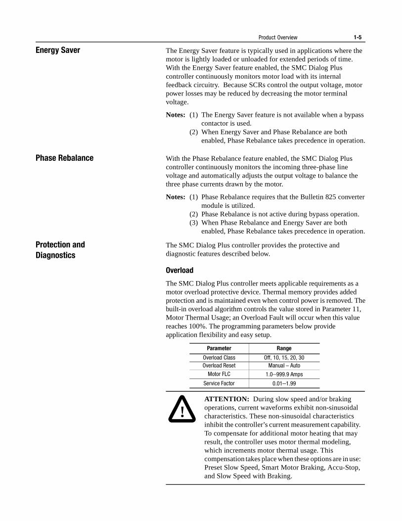
The SMC Dialog Plus controller meets applicable requirements as a motor overload protective device. Thermal memory provides added protection and is maintained even when control power is removed. The built-in overload algorithm controls the value stored in Parameter 11, Motor Thermal Usage; an Overload Fault will occur when this value reaches 100%. The programming parameters below provide application flexibility and easy setup.
Parameter Range
Overload Class Off, 10, 15, 20, 30Overload Reset Manual – Auto
Motor FLC 1.0–999.9 Amps
Service Factor 0.01–1.99
!ATTENTION: During slow speed and/or braking operations, current waveforms exhibit non-sinusoidal characteristics. These non-sinusoidal characteristics inhibit the controller’s current measurement capability. To compensate for additional motor heating that may result, the controller uses motor thermal modeling, which increments motor thermal usage. This compensation takes place when these options are in use: Preset Slow Speed, Smart Motor Braking, Accu-Stop, and Slow Speed with Braking.
1-6 Product Overview
Protection and Diagnostics (cont.)
Notes: (1) The factory default setting for Overload Class, which is “Off,” disables overload protection. An overload trip class and the motor’s full load current rating must be programmed to enable overload protection.
(2) The current sensing capability of the SMC Dialog Plus controller is disabled during bypass operation. Using a Bulletin 825 converter module in these applications is recommended to provide current feedback. Otherwise, a separate overload relay is required.
(3) Motors with full load current ratings of 5 Amps and below may require the use of the converter module (Cat. No. 825-MCM20) for improved current measurement accuracy.
(4) Automatic reset of an overload fault requires the start input to be cycled in a 2-wire control scheme. This applies to the following firmware releases: 1.07 (standard), 1A07L (Soft Stop) and 1B05L (Pump Control) or earlier.
Figure 1.6 and Figure 1.7 provide the overload trip curves for the available trip classes.
Product Overview 1-7
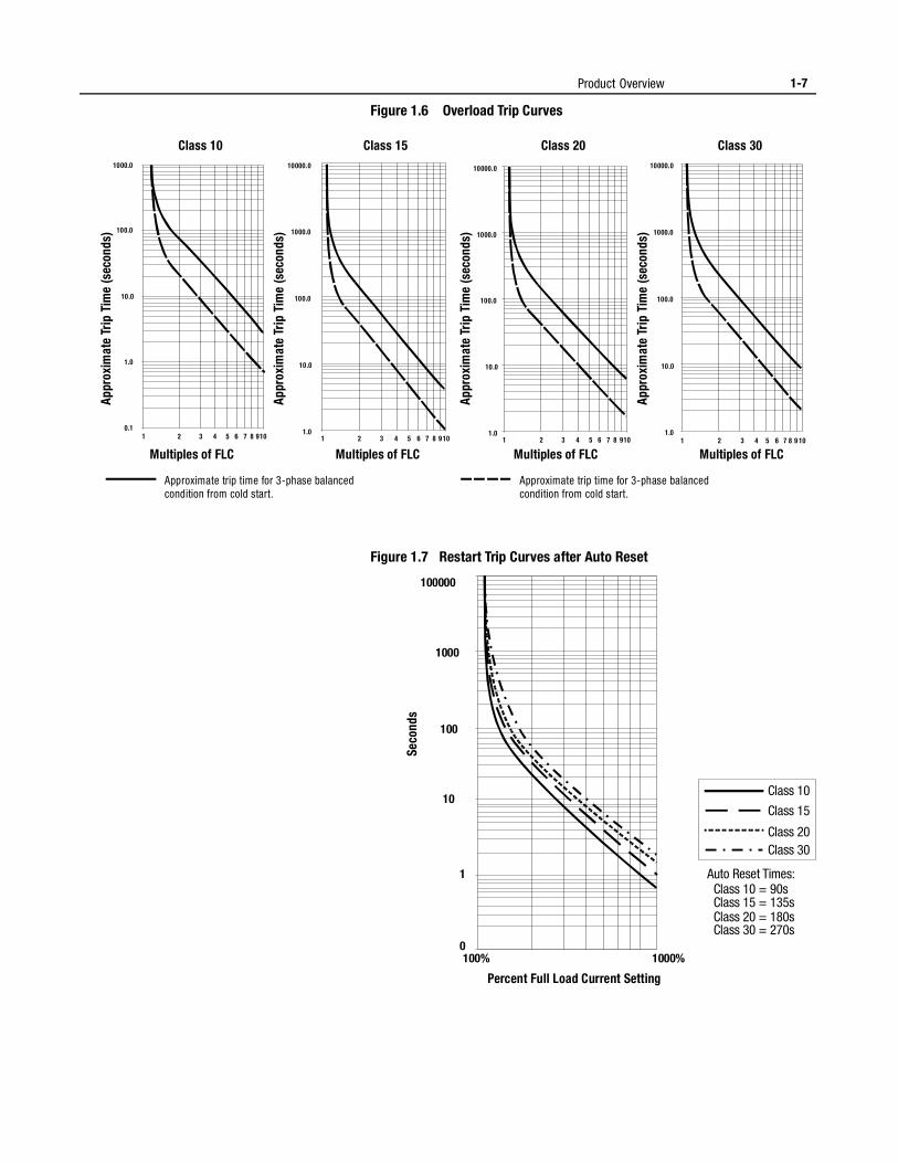
Figure 1.6 Overload Trip Curves
Figure 1.7 Restart Trip Curves after Auto Reset
Approximate trip time for 3-phase balancedcondition from cold start.
Approximate trip time for 3-phase balancedcondition from cold start.
Class 10 Class 15 Class 20 Class 30
Multiples of FLC Multiples of FLC Multiples of FLC Multiples of FLC
Appr
oxim
ate
Trip
Tim
e (s
econ
ds)
Appr
oxim
ate
Trip
Tim
e (s
econ
ds)
Appr
oxim
ate
Trip
Tim
e (s
econ
ds)
Appr
oxim
ate
Trip
Tim
e (s
econ
ds)
1.0
10.0
100.0
1000.0
10000.0
1 10 2 3 9 8 7 6 5 4 0.1
1.0
10.0
100.0
1000.0
1 10 2 3 9 8 7 6 5 4 1.0
10.0
100.0
1000.0
10000.0
1 10 2 3 9 8 7 6 5 4 1.0
10.0
100.0
1000.0
10000.0
1 10 2 3 9 8 7 6 5 4
1000% 100% 0
1
10
100
1000
100000
Percent Full Load Current Setting
Seco
nds
Class 10
Class 15
Class 20 Class 30
Auto Reset Times: Class 10 = 90s Class 15 = 135s Class 20 = 180s Class 30 = 270s
1-8 Product Overview
Protection and Diagnostics(cont.)
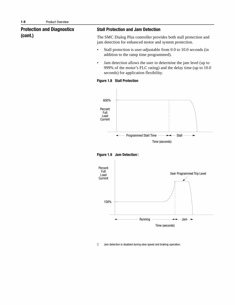
Stall Protection and Jam Detection
The SMC Dialog Plus controller provides both stall protection and jam detection for enhanced motor and system protection.
• Stall protection is user-adjustable from 0.0 to 10.0 seconds (in addition to the ramp time programmed).
• Jam detection allows the user to determine the jam level (up to 999% of the motor’s FLC rating) and the delay time (up to 10.0 seconds) for application flexibility.
Figure 1.8 Stall Protection
Figure 1.9 Jam Detection①
① Jam detection is disabled during slow speed and braking operation.
Stall
600%
Percent Full Load
Current
Time (seconds)
Programmed Start Time
100%
Running Jam
Percent Full Load
Current
Time (seconds)
User Programmed Trip Level
Product Overview 1-9
Open Gate
An open gate fault indicates that improper SCR firing, typically caused by an open SCR gate, has been detected on one of the power poles. Before the controller shuts down, it will attempt to start the motor a total of three times.
Line Faults
The SMC Dialog Plus controller continually monitors line conditions for abnormal factors. Pre-start protection includes:
• Power Loss (with phase indication)
• Line Fault (with phase indication)
– Power loss
– Missing load connection
– Shorted SCR
Running protection includes:
• Line Fault (no phase indication)
– Power loss
– Missing load connection
– Shorted SCR
Additional programmable parameters are provided for the following protective features:
• Undervoltage① can be adjusted from 0 to 99% of the programmed line voltage and has a programmable delay time of 0 to 99 seconds.
• Overvoltage① can be adjusted from 0 to 199% of the programmed line voltage and has a programmable delay time of 0 to 99 seconds.
• Phase reversal② protection can be toggled either On or Off.
• Voltage unbalance① protection can be programmed for trip levels of 0 to 25% with a programmable delay time of 0 to 99 seconds.
Underload③
Utilizing the underload protection of the SMC Dialog Plus controller, motor operation can be halted if a sudden drop in current is sensed.
The SMC Dialog Plus controller provides an adjustable underload trip setting from 0 to 99% of the programmed motor full load current rating. Trip delay time can be adjusted from 0 to 99 seconds.
① Undervoltage, overvoltage, and voltage unbalance protection are disabled during braking operation.
② Phase reversal protection is functional only at pre-start.
③ Underload protection is disabled during slow speed and braking operations.
1-10 Product Overview
Protection and Diagnostics(cont.)
Excessive Starts/Hour
The SMC Dialog Plus controller allows the user to program the allowed number of starts per hour (up to 99). This helps eliminate motor stress caused by repeated starting over a short time period.
Overtemperature
The SMC Dialog Plus controller monitors the temperature of the SCRs by using internal thermistors. When the power poles’ maximum rated temperature is reached, SCR firing is inhibited.
An overtemperature condition can indicate inadequate ventilation, high ambient temperature, overloading, or excessive cycling. After the SCR temperature is reduced to allowable levels, the fault can be cleared (see page 9-1 for instructions).
Metering Power monitoring parameters include:
• Three-phase current
• Three-phase voltage
• Power in kW
• Power usage in kWH
• Power factor
• Motor thermal capacity usage
• Elapsed time
Notes: (1) The current sensing capability of the SMC Dialog Plus controller is disabled during bypass operation. A Bulletin 825 converter module is required to maintain the three-phase current, kW, kWH, and motor thermal capacity measurements.
(2) Current measurement is not available during the slow speed and/or braking operations of the Preset Slow Speed, SMB Smart Motor Braking, Accu-Stop and Slow Speed with Braking control options.
(3) Voltage measurement is not available during the brakingoperation of the SMB Smart Motor Braking, Accu-Stop, and Slow Speed with Braking control options.
(4) The power factor parameter is provided as a displacementpower factor value. Power factor measurement is disabled during bypass operation.
(5) The elapsed time and kWH values are automatically saved to memory every 12 hours.
(6) Motor thermal capacity usage is determined by the built-in electronic thermal overload protection system. An overload fault occurs when this value reaches 100%.
Product Overview 1-11
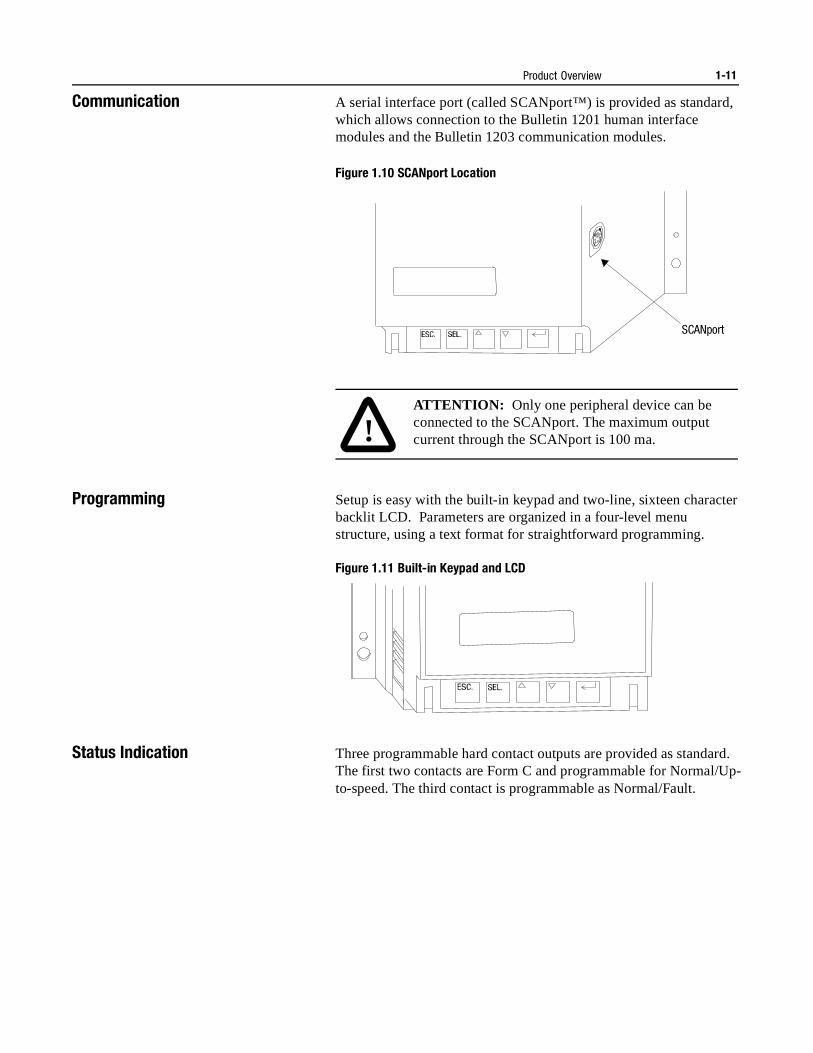
Communication A serial interface port (called SCANport™) is provided as standard, which allows connection to the Bulletin 1201 human interface modules and the Bulletin 1203 communication modules.
Figure 1.10 SCANport Location
Programming Setup is easy with the built-in keypad and two-line, sixteen character backlit LCD. Parameters are organized in a four-level menu structure, using a text format for straightforward programming.
Figure 1.11 Built-in Keypad and LCD
Status Indication Three programmable hard contact outputs are provided as standard. The first two contacts are Form C and programmable for Normal/Up-to-speed. The third contact is programmable as Normal/Fault.
SCANport
!ATTENTION: Only one peripheral device can be connected to the SCANport. The maximum output current through the SCANport is 100 ma.
1-12 Product Overview
Control Options The SMC Dialog Plus controller offers the control options described below.
Important: The options listed in this section are mutually exclusive and must be specified when ordering. An existing controller may be upgraded to another control option by replacing the control module. Consult your nearest/local Allen-Bradley sales office.
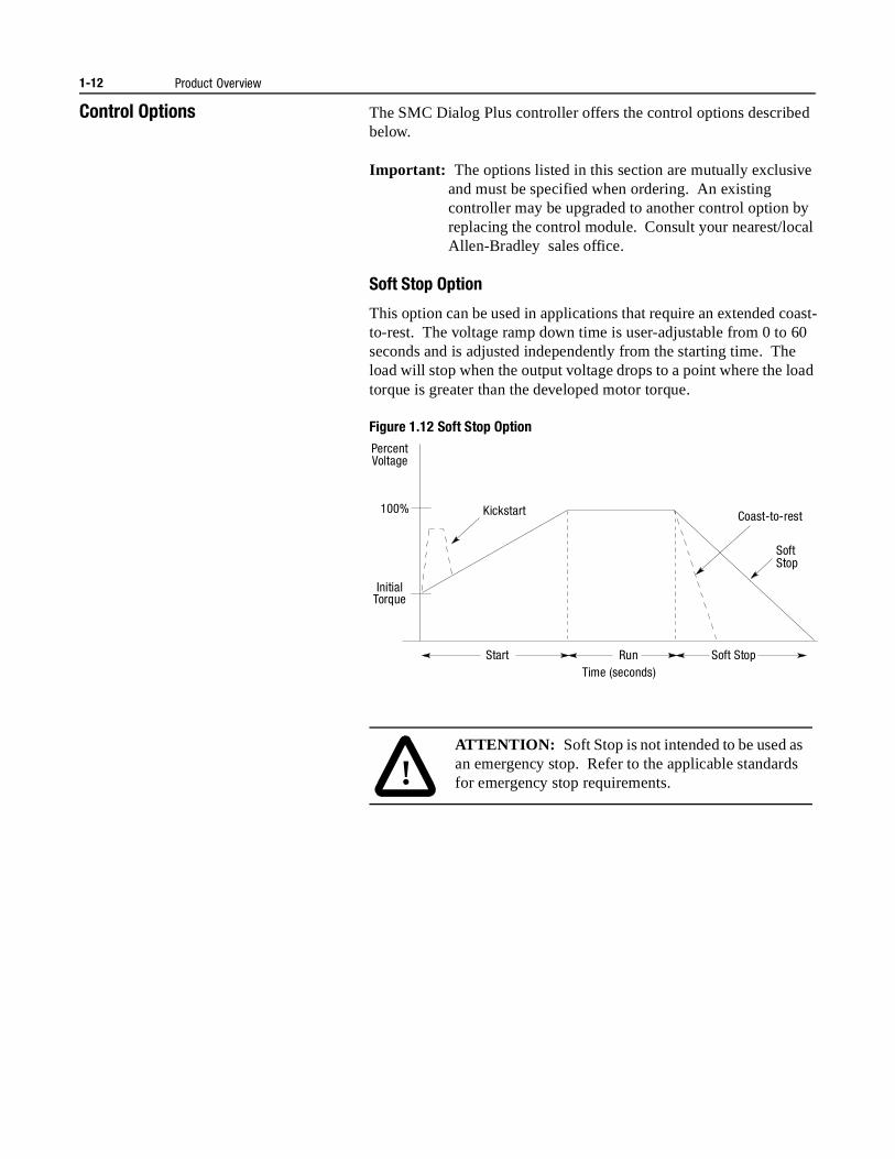
Soft Stop Option
This option can be used in applications that require an extended coast-to-rest. The voltage ramp down time is user-adjustable from 0 to 60 seconds and is adjusted independently from the starting time. The load will stop when the output voltage drops to a point where the load torque is greater than the developed motor torque.
Figure 1.12 Soft Stop Option
Start Run Soft Stop
Coast-to-rest
Soft Stop
Kickstart
Initial Torque
100%
Percent Voltage
Time (seconds)
!ATTENTION: Soft Stop is not intended to be used as an emergency stop. Refer to the applicable standards for emergency stop requirements.
Product Overview 1-13
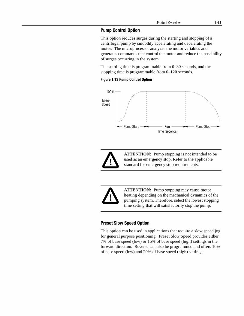
Pump Control Option
This option reduces surges during the starting and stopping of a centrifugal pump by smoothly accelerating and decelerating the motor. The microprocessor analyzes the motor variables and generates commands that control the motor and reduce the possibility of surges occurring in the system.
The starting time is programmable from 0–30 seconds, and the stopping time is programmable from 0–120 seconds.
Figure 1.13 Pump Control Option
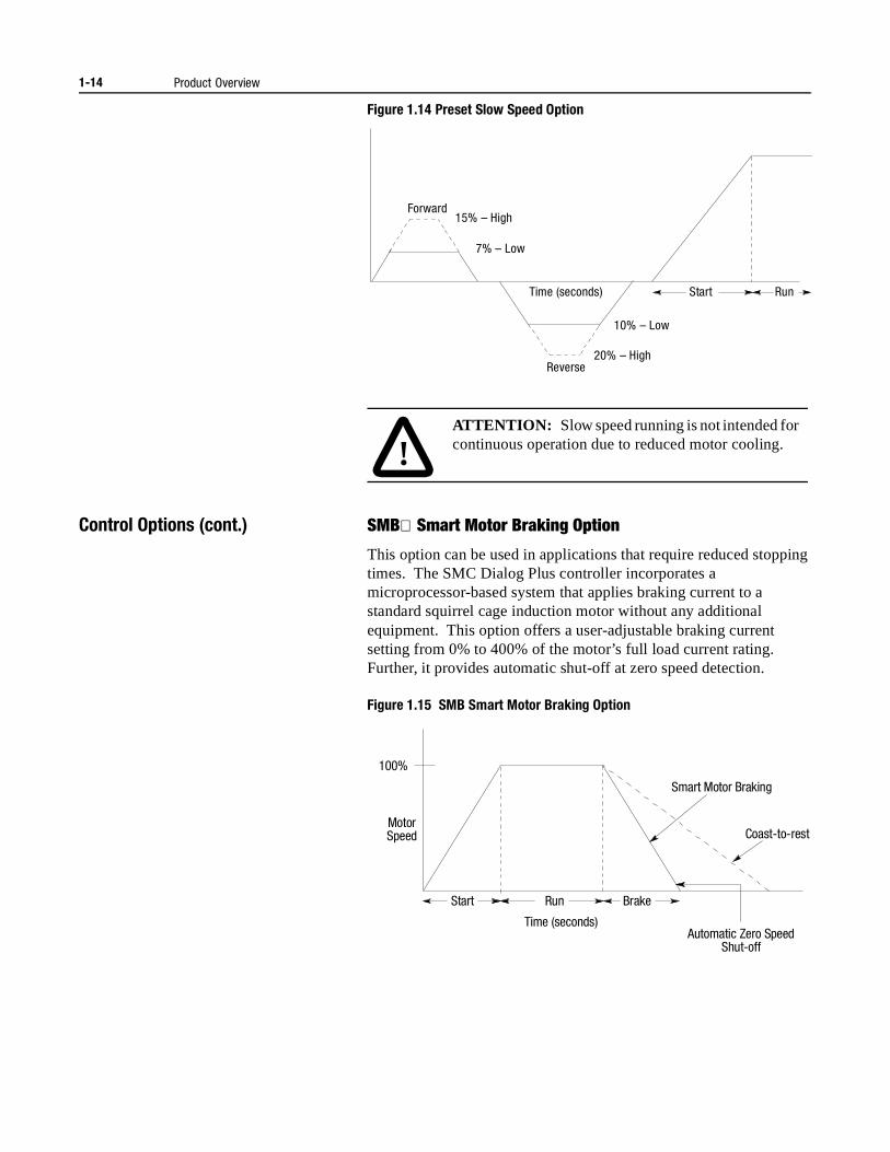
Preset Slow Speed Option
This option can be used in applications that require a slow speed jog for general purpose positioning. Preset Slow Speed provides either 7% of base speed (low) or 15% of base speed (high) settings in the forward direction. Reverse can also be programmed and offers 10% of base speed (low) and 20% of base speed (high) settings.
Pump Start Run Pump Stop
Motor Speed
100%
Time (seconds)
!ATTENTION: Pump stopping is not intended to be used as an emergency stop. Refer to the applicable standard for emergency stop requirements.
!ATTENTION: Pump stopping may cause motor heating depending on the mechanical dynamics of the pumping system. Therefore, select the lowest stopping time setting that will satisfactorily stop the pump.
1-14 Product Overview
Figure 1.14 Preset Slow Speed Option
Control Options (cont.) SMB Smart Motor Braking Option
This option can be used in applications that require reduced stopping times. The SMC Dialog Plus controller incorporates a microprocessor-based system that applies braking current to a standard squirrel cage induction motor without any additional equipment. This option offers a user-adjustable braking current setting from 0% to 400% of the motor’s full load current rating. Further, it provides automatic shut-off at zero speed detection.
Figure 1.15 SMB Smart Motor Braking Option
Forward 15% – High
7% – Low
10% – Low
20% – High Reverse
Run Start Time (seconds)
!ATTENTION: Slow speed running is not intended for continuous operation due to reduced motor cooling.
Start
Motor Speed
100%
Run
Automatic Zero Speed Shut-off
Brake
Smart Motor Braking
Coast-to-rest
Time (seconds)
Product Overview 1-15
Note: All braking current settings in the range of 1–100% will provide 100% braking current to the motor.
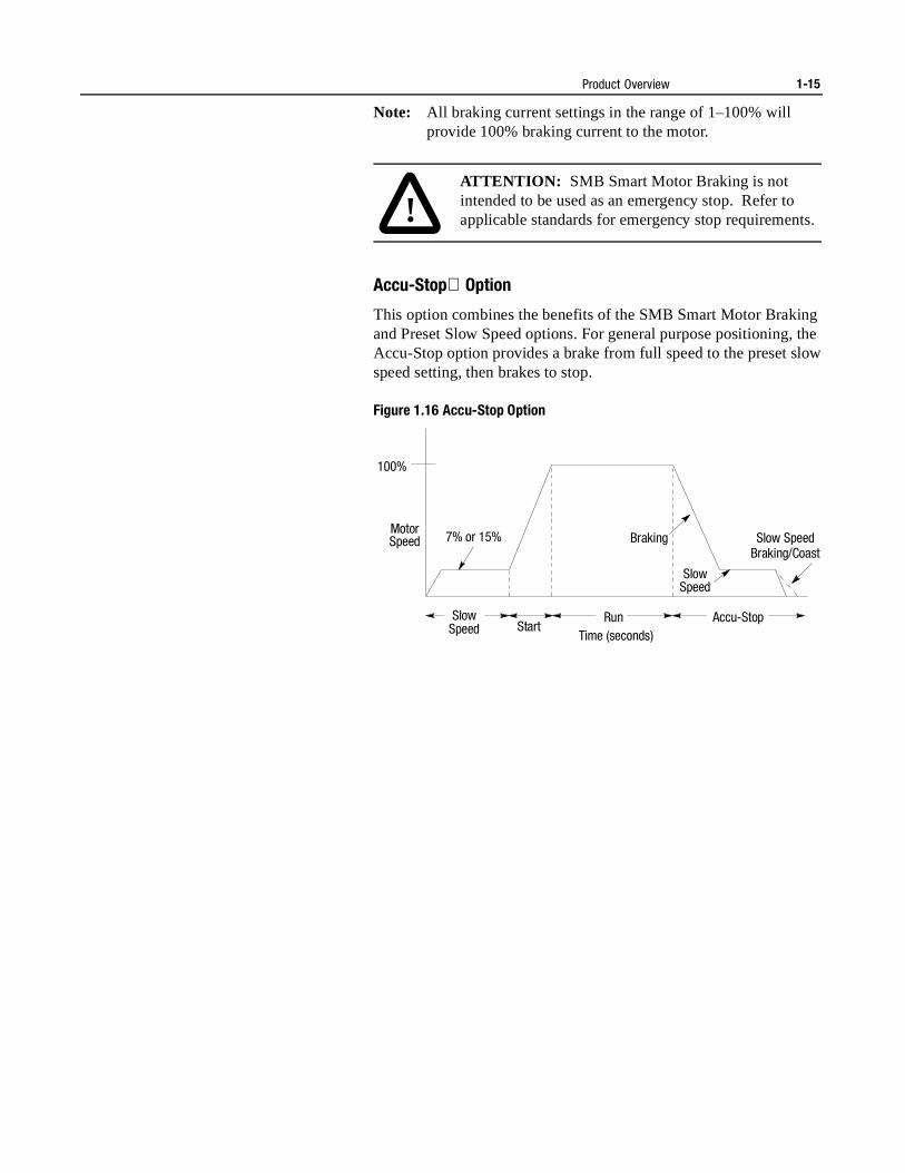
Accu-Stop Option
This option combines the benefits of the SMB Smart Motor Braking and Preset Slow Speed options. For general purpose positioning, the Accu-Stop option provides a brake from full speed to the preset slow speed setting, then brakes to stop.
Figure 1.16 Accu-Stop Option
!ATTENTION: SMB Smart Motor Braking is not intended to be used as an emergency stop. Refer to applicable standards for emergency stop requirements.
Start Run
Motor Speed
100%
Slow Speed
Accu-Stop
Braking
Slow Speed
Slow SpeedBraking/Coast
7% or 15%
Time (seconds)
1-16 Product Overview
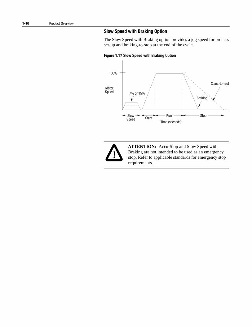
Slow Speed with Braking Option
The Slow Speed with Braking option provides a jog speed for process set-up and braking-to-stop at the end of the cycle.
Figure 1.17 Slow Speed with Braking Option
Motor Speed
100%
Start Run Slow
Speed
Braking 7% or 15%
Stop
Coast-to-rest
Time (seconds)
!ATTENTION: Accu-Stop and Slow Speed with Braking are not intended to be used as an emergency stop. Refer to applicable standards for emergency stop requirements.
Chapter 2
Installation
Receiving It is the responsibility of the user to thoroughly inspect the equipment before accepting the shipment from the freight company. Check the item(s) received against the purchase order. If any items are damaged, it is the responsibility of the user not to accept delivery until the freight agent has noted the damage on the freight bill. Should any concealed damage be found during unpacking, it is again the responsibility of the user to notify the freight agent. The shipping container must be left intact and the freight agent should be requested to make a visual inspection of the equipment.
Unpacking Remove all packing material, wedges, or braces from within and around the controller. Remove all packing material from the heat sink.
Inspecting After unpacking, check the item(s’) nameplate catalog number against the purchase order.
Storing The controller should remain in its shipping container prior to installation. If the equipment is not to be used for a period of time, it must be stored according to the following instructions in order to maintain warranty coverage.
• Store in a clean, dry location.
• Store within an ambient temperature range of –20°C to +75°C (–4°F to +167°F).
• Store within a relative humidity range of 0% to 95%, noncondensing.
• Do not store equipment where it could be exposed to a corrosive atmosphere.
• Do not store equipment in a construction area.
2-2 Installation
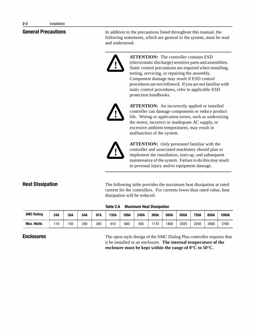
General Precautions In addition to the precautions listed throughout this manual, the following statements, which are general to the system, must be read and understood.
Heat Dissipation The following table provides the maximum heat dissipation at rated current for the controllers. For currents lower than rated value, heat dissipation will be reduced.
Table 2.A Maximum Heat Dissipation
Enclosures The open-style design of the SMC Dialog Plus controller requires that it be installed in an enclosure. The internal temperature of the enclosure must be kept within the range of 0°C to 50°C.
!ATTENTION: The controller contains ESD (electrostatic discharge) sensitive parts and assemblies. Static control precautions are required when installing, testing, servicing, or repairing the assembly. Component damage may result if ESD control procedures are not followed. If you are not familiar with static control procedures, refer to applicable ESD protection handbooks.
!ATTENTION: An incorrectly applied or installed controller can damage components or reduce product life. Wiring or application errors, such as undersizing the motor, incorrect or inadequate AC supply, or excessive ambient temperatures, may result in malfunction of the system.
!ATTENTION: Only personnel familiar with the controller and associated machinery should plan or implement the installation, start-up, and subsequent maintenance of the system. Failure to do this may result in personal injury and/or equipment damage.
SMC Rating 24A 35A 54A 97A 135A 180A 240A 360A 500A 650A 720A 850A 1000A
Max. Watts 110 150 200 285 410 660 935 1170 1400 2025 2250 2400 2760
Installation 2-3
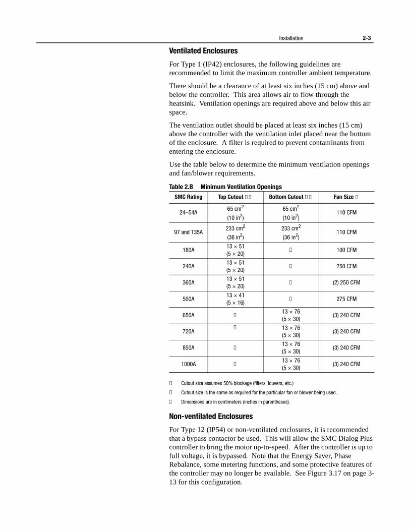
Ventilated Enclosures
For Type 1 (IP42) enclosures, the following guidelines are recommended to limit the maximum controller ambient temperature.
There should be a clearance of at least six inches (15 cm) above and below the controller. This area allows air to flow through the heatsink. Ventilation openings are required above and below this air space.
The ventilation outlet should be placed at least six inches (15 cm) above the controller with the ventilation inlet placed near the bottom of the enclosure. A filter is required to prevent contaminants from entering the enclosure.
Use the table below to determine the minimum ventilation openings and fan/blower requirements.
Table 2.B Minimum Ventilation Openings
① Cutout size assumes 50% blockage (filters, louvers, etc.)
② Cutout size is the same as required for the particular fan or blower being used.
③ Dimensions are in centimeters (inches in parentheses).
Non-ventilated Enclosures
For Type 12 (IP54) or non-ventilated enclosures, it is recommended that a bypass contactor be used. This will allow the SMC Dialog Plus controller to bring the motor up-to-speed. After the controller is up to full voltage, it is bypassed. Note that the Energy Saver, Phase Rebalance, some metering functions, and some protective features of the controller may no longer be available. See Figure 3.17 on page 3-13 for this configuration.
SMC Rating Top Cutout ①③ Bottom Cutout ①③ Fan Size ①
24–54A65 cm2
(10 in2)
65 cm2
(10 in2)110 CFM
97 and 135A233 cm2
(36 in2)
233 cm2
(36 in2)110 CFM
180A13 × 51(5 × 20)
② 100 CFM
240A13 × 51(5 × 20)
② 250 CFM
360A13 × 51(5 × 20)
② (2) 250 CFM
500A13 × 41(5 × 16)
② 275 CFM
650A ②13 × 76(5 × 30)
(3) 240 CFM
720A② 13 × 76
(5 × 30)(3) 240 CFM
850A ②13 × 76(5 × 30)
(3) 240 CFM
1000A ②13 × 76(5 × 30)
(3) 240 CFM
2-4 Installation
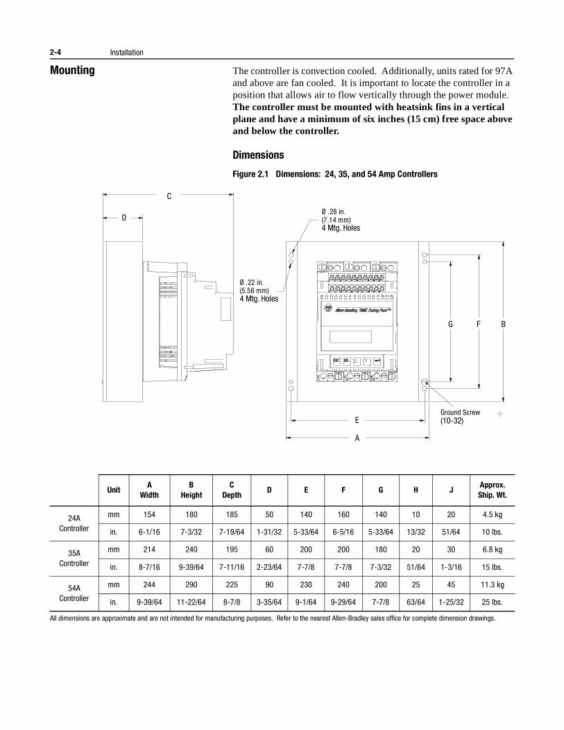
Mounting The controller is convection cooled. Additionally, units rated for 97A and above are fan cooled. It is important to locate the controller in a position that allows air to flow vertically through the power module. The controller must be mounted with heatsink fins in a vertical plane and have a minimum of six inches (15 cm) free space above and below the controller.
Dimensions
Figure 2.1 Dimensions: 24, 35, and 54 Amp Controllers
All dimensions are approximate and are not intended for manufacturing purposes. Refer to the nearest Allen-Bradley sales office for complete dimension drawings.
UnitA
WidthB
HeightC
DepthD E F G H J
Approx.Ship. Wt.
24AController
mm 154 180 185 50 140 160 140 10 20 4.5 kg
in. 6-1/16 7-3/32 7-19/64 1-31/32 5-33/64 6-5/16 5-33/64 13/32 51/64 10 lbs.
35AController
mm 214 240 195 60 200 200 180 20 30 6.8 kg
in. 8-7/16 9-39/64 7-11/16 2-23/64 7-7/8 7-7/8 7-3/32 51/64 1-3/16 15 lbs.
54AController
mm 244 290 225 90 230 240 200 25 45 11.3 kg
in. 9-39/64 11-22/64 8-7/8 3-35/64 9-1/64 9-29/64 7-7/8 63/64 1-25/32 25 lbs.
Ø .22 in. (5.56 mm) 4 Mtg. Holes
Ø .28 in. (7.14 mm) 4 Mtg. Holes
A
E
G F B
D
C
Ground Screw (10-32)
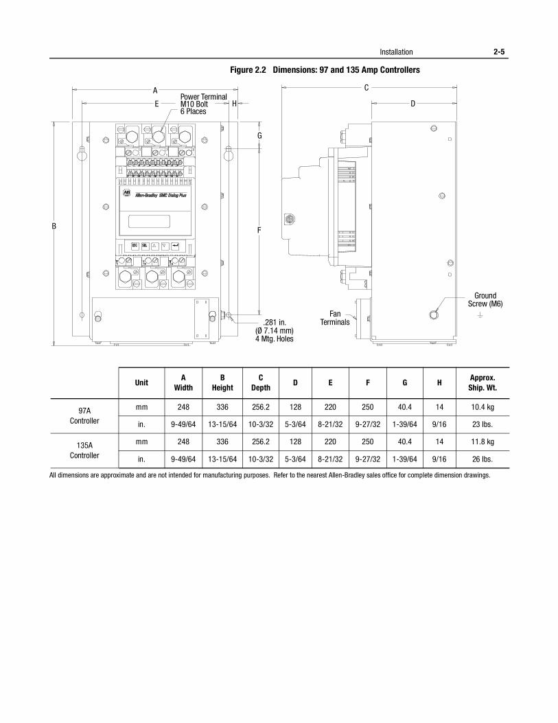
Installation 2-5
Figure 2.2 Dimensions: 97 and 135 Amp Controllers
All dimensions are approximate and are not intended for manufacturing purposes. Refer to the nearest Allen-Bradley sales office for complete dimension drawings.
UnitA
WidthB
HeightC
DepthD E F G H
Approx.Ship. Wt.
97AController
mm 248 336 256.2 128 220 250 40.4 14 10.4 kg
in. 9-49/64 13-15/64 10-3/32 5-3/64 8-21/32 9-27/32 1-39/64 9/16 23 lbs.
135AController
mm 248 336 256.2 128 220 250 40.4 14 11.8 kg
in. 9-49/64 13-15/64 10-3/32 5-3/64 8-21/32 9-27/32 1-39/64 9/16 26 lbs.
B
G
C
D H
A
E
.281 in. (Ø 7.14 mm) 4 Mtg. Holes
Fan Terminals
Ground Screw (M6)
Power Terminal M10 Bolt 6 Places
F
2-6 Installation
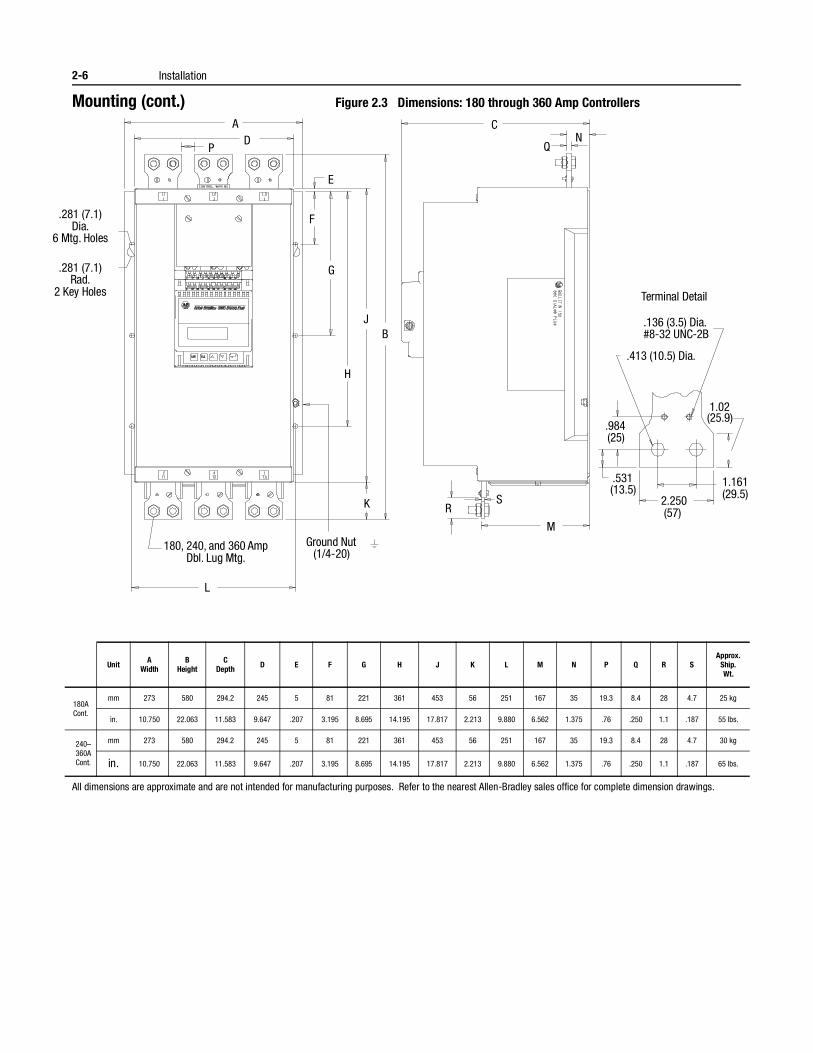
Mounting (cont.) Figure 2.3 Dimensions: 180 through 360 Amp Controllers
All dimensions are approximate and are not intended for manufacturing purposes. Refer to the nearest Allen-Bradley sales office for complete dimension drawings.
UnitA
WidthB
HeightC
Depth D E F G H J K L M N P Q R SApprox.
Ship.Wt.
180ACont.
mm 273 580 294.2 245 5 81 221 361 453 56 251 167 35 19.3 8.4 28 4.7 25 kg
in. 10.750 22.063 11.583 9.647 .207 3.195 8.695 14.195 17.817 2.213 9.880 6.562 1.375 .76 .250 1.1 .187 55 lbs.
240–360ACont.
mm 273 580 294.2 245 5 81 221 361 453 56 251 167 35 19.3 8.4 28 4.7 30 kg
in. 10.750 22.063 11.583 9.647 .207 3.195 8.695 14.195 17.817 2.213 9.880 6.562 1.375 .76 .250 1.1 .187 65 lbs.
Terminal Detail
.136 (3.5) Dia. #8-32 UNC-2B
.413 (10.5) Dia.
.984 (25)
.531 (13.5)
1.161 (29.5) 2.250
(57)
1.02 (25.9)
S R
M
Q N
C
B J
H
G
F
E
P D
A
180, 240, and 360 Amp Dbl. Lug Mtg.
L
K
.281 (7.1) Rad.
2 Key Holes
.281 (7.1) Dia.
6 Mtg. Holes
Ground Nut (1/4-20)
Installation 2-7
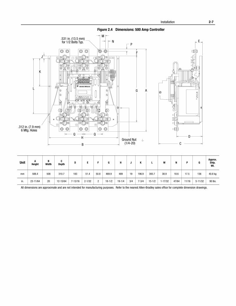
Figure 2.4 Dimensions: 500 Amp Controller
All dimensions are approximate and are not intended for manufacturing purposes. Refer to the nearest Allen-Bradley sales office for complete dimension drawings.
Unit AHeight
BWidth
CDepth D E F G H J K L M N P Q
Approx.Ship.Wt.
mm 588.4 508 310.7 183 51.4 50.8 469.9 489 19 196.9 393.7 38.9 18.6 17.5 136 40.8 kg
in. 23-11/64 20 12-15/64 7-13/16 2-1/32 2 18-1/2 19-1/4 3/4 7-3/4 15-1/2 1-17/32 47/64 11/16 5-11/32 90 lbs.
A G
F
P N
M
J
K
L
H
B C
D
E
.312 in. (7.9 mm) 6 Mtg. Holes
.531 in. (13.5 mm) for 1/2 Bolts Typ.
Ground Nut (1/4-20)
Q Q
2-8 Installation
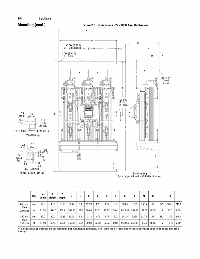
Mounting (cont.) Figure 2.5 Dimensions: 650-1000 Amp Controllers
All dimensions are approximate and are not intended for manufacturing purposes. Refer to the nearest Allen-BradleyAllen-Bradley sales office for complete dimension drawings.
UnitA
WidthB
HeightC
DepthD E F G H J K L M N P Q R
650 and 720A
Controller
mm 32.0 60.0 15.83 30.25 6.0 12.13 .875 .875 2.0 58.25 9.935 5.475 .75 329 317.5 246.1
in. 812.8 1524.0 402.1 768.35 152.4 308.0 22.22 22.23 50.8 1479.55 252.35 139.06 19.05 13 12.5 9.69
850 and 1000A
Controller
mm 32.0 60.0 15.83 30.25 6.0 12.13 .875 .875 2.0 58.25 9.935 5.475 .75 383 375 246.1
in. 812.8 1524.0 402.1 768.35 152.4 308.0 22.22 22.23 50.8 1479.55 252.35 139.06 19.05 15 14.75 9.69
.5 Dia. (Ø 12.7) 6 – Holes
.56 Dia. (Ø 14.2) 2 – Lifting Holes
D
A
G
Q P
.105 Steel Sheet (2.67)
4.0 (101.6)
2.0(50.8)
.688 (17.5)
.515 (13.1)
Dia. Typ.
1.312 (33.3)
650–720 Amp
.688 (17.5)
.67 (17)
.64 (16.3) Typ.
.64 (16.3)
850–1000 Amp
5.0 (127)
2.5 (63.5)
Typical Line and Load Bus
.75 Dia. (Ø 19.1) 2 – Holes
Grounding Lug (wide range: #6 solid to 250 MCM stranded)
1.312 (33.3)
.64 (16.3)
H
C
L
M
T
B
K
J
N
E F
R R
Installation 2-9
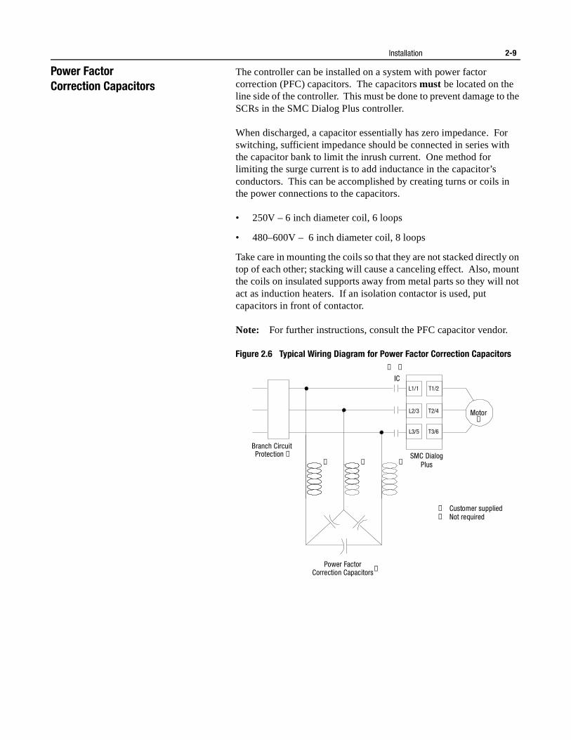
Power Factor Correction Capacitors
The controller can be installed on a system with power factor correction (PFC) capacitors. The capacitors must be located on the line side of the controller. This must be done to prevent damage to the SCRs in the SMC Dialog Plus controller.
When discharged, a capacitor essentially has zero impedance. For switching, sufficient impedance should be connected in series with the capacitor bank to limit the inrush current. One method for limiting the surge current is to add inductance in the capacitor’s conductors. This can be accomplished by creating turns or coils in the power connections to the capacitors.
• 250V – 6 inch diameter coil, 6 loops
• 480–600V – 6 inch diameter coil, 8 loops
Take care in mounting the coils so that they are not stacked directly on top of each other; stacking will cause a canceling effect. Also, mount the coils on insulated supports away from metal parts so they will not act as induction heaters. If an isolation contactor is used, put capacitors in front of contactor.
Note: For further instructions, consult the PFC capacitor vendor.
Figure 2.6 Typical Wiring Diagram for Power Factor Correction Capacitors
Power Factor Correction Capacitors
SMC DialogPlus
Motor
Branch Circuit Protection ➀
➀ Customer supplied ➁ Not required
IC L1/1 T1/2
L2/3 T2/4
L3/5 T3/6
➀
➀
➀ ➀ ➀
➀
➁
2-10 Installation
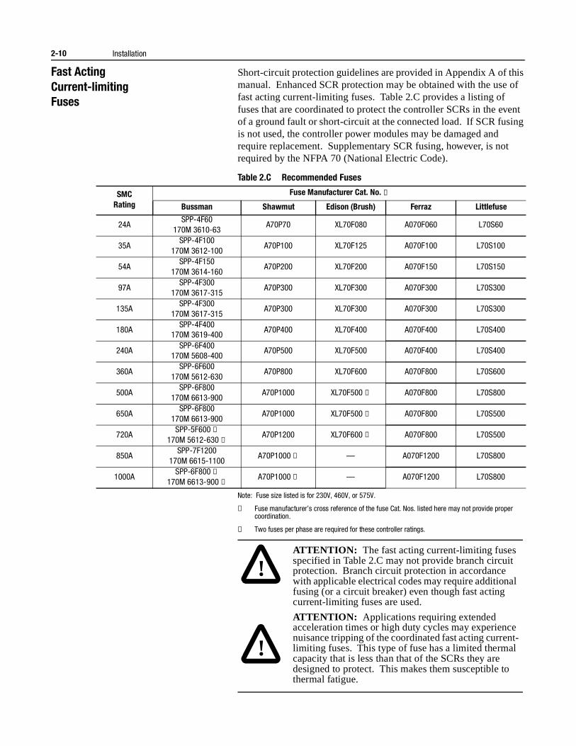
Fast ActingCurrent-limitingFuses
Short-circuit protection guidelines are provided in Appendix A of this manual. Enhanced SCR protection may be obtained with the use of fast acting current-limiting fuses. Table 2.C provides a listing of fuses that are coordinated to protect the controller SCRs in the event of a ground fault or short-circuit at the connected load. If SCR fusing is not used, the controller power modules may be damaged and require replacement. Supplementary SCR fusing, however, is not required by the NFPA 70 (National Electric Code).
Table 2.C Recommended Fuses
Note: Fuse size listed is for 230V, 460V, or 575V.
① Fuse manufacturer’s cross reference of the fuse Cat. Nos. listed here may not provide proper coordination.
② Two fuses per phase are required for these controller ratings.
SMCRating
Fuse Manufacturer Cat. No. ①
Bussman Shawmut Edison (Brush) Ferraz Littlefuse
24ASPP-4F60
170M 3610-63A70P70 XL70F080 A070F060 L70S60
35ASPP-4F100
170M 3612-100A70P100 XL70F125 A070F100 L70S100
54ASPP-4F150
170M 3614-160A70P200 XL70F200 A070F150 L70S150
97ASPP-4F300
170M 3617-315A70P300 XL70F300 A070F300 L70S300
135ASPP-4F300
170M 3617-315A70P300 XL70F300 A070F300 L70S300
180ASPP-4F400
170M 3619-400A70P400 XL70F400 A070F400 L70S400
240ASPP-6F400
170M 5608-400A70P500 XL70F500 A070F400 L70S400
360ASPP-6F600
170M 5612-630A70P800 XL70F600 A070F800 L70S600
500ASPP-6F800
170M 6613-900A70P1000 XL70F500 ② A070F800 L70S800
650ASPP-6F800
170M 6613-900A70P1000 XL70F500 ② A070F800 L70S500
720ASPP-5F600 ②
170M 5612-630 ②A70P1200 XL70F600 ② A070F800 L70S500
850ASPP-7F1200
170M 6615-1100A70P1000 ② — A070F1200 L70S800
1000ASPP-6F800 ②
170M 6613-900 ②A70P1000 ② — A070F1200 L70S800
!
!
ATTENTION: The fast acting current-limiting fuses specified in Table 2.C may not provide branch circuit protection. Branch circuit protection in accordance with applicable electrical codes may require additional fusing (or a circuit breaker) even though fast acting current-limiting fuses are used.
ATTENTION: Applications requiring extended acceleration times or high duty cycles may experience nuisance tripping of the coordinated fast acting current-limiting fuses. This type of fuse has a limited thermal capacity that is less than that of the SCRs they are designed to protect. This makes them susceptible to thermal fatigue.
Installation 2-11
Protective Modules Protective modules containing metal oxide varistors (MOVs) and capacitors can be installed on controllers rated 24A to 360A to protect the power components from electrical transients and/or high electrical noise. The protective modules clip voltage transients generated on the lines to prevent such surges from damaging the SCRs. The capacitors in the protective modules are used to shunt noise energy away from the controller electronics. Surge protection is provided as standard for controllers rated 500–1000A.
Motor OverloadProtection
Thermal motor overload protection is provided as standard (though it must be programmed) with the SMC Dialog Plus controller. If the overload trip class is less than the acceleration time of the motor, nuisance tripping may occur.
Three special applications require consideration: bypass, two-speed motors, and multi-motor protection.
Bypass
In a bypass configuration, the SMC Dialog Plus controller loses current sensing capability. It is recommended that a Bulletin 825 converter module be used to provide current feedback to the SMC Dialog Plus controller for these applications to maintain the thermal memory and to maintain the SMC Dialog Plus controller’s power monitoring capability. It is possible, however, to use a traditional electromechanical overload relay for bypass configurations.
Two-speed Motors
The SMC Dialog Plus controller has overload protection available for single speed motors. When the SMC Dialog Plus controller is applied to a two-speed motor, the Overload Class parameter must be programmed to OFF and separate overload relays must be provided for each speed.
Multi-motor Protection
If the SMC Dialog Plus controller is controlling more than one motor, individual overload protection is required for each motor.
!ATTENTION: When installing or inspecting the protective module, make sure that the controller has been disconnected from the power source. The protective module should be inspected periodically for damage or discoloration. Replace if necessary.
!ATTENTION: Overload protection should be properly coordinated with the motor.
2-12 Installation
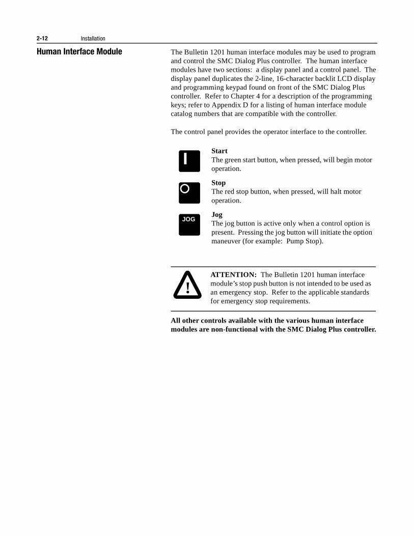
Human Interface Module The Bulletin 1201 human interface modules may be used to program and control the SMC Dialog Plus controller. The human interface modules have two sections: a display panel and a control panel. The display panel duplicates the 2-line, 16-character backlit LCD display and programming keypad found on front of the SMC Dialog Plus controller. Refer to Chapter 4 for a description of the programming keys; refer to Appendix D for a listing of human interface module catalog numbers that are compatible with the controller.
The control panel provides the operator interface to the controller.
All other controls available with the various human interface modules are non-functional with the SMC Dialog Plus controller.
StartThe green start button, when pressed, will begin motor operation.
StopThe red stop button, when pressed, will halt motor operation.
JogThe jog button is active only when a control option is present. Pressing the jog button will initiate the option maneuver (for example: Pump Stop).
JOG
!ATTENTION: The Bulletin 1201 human interface module’s stop push button is not intended to be used as an emergency stop. Refer to the applicable standards for emergency stop requirements.
Installation 2-13
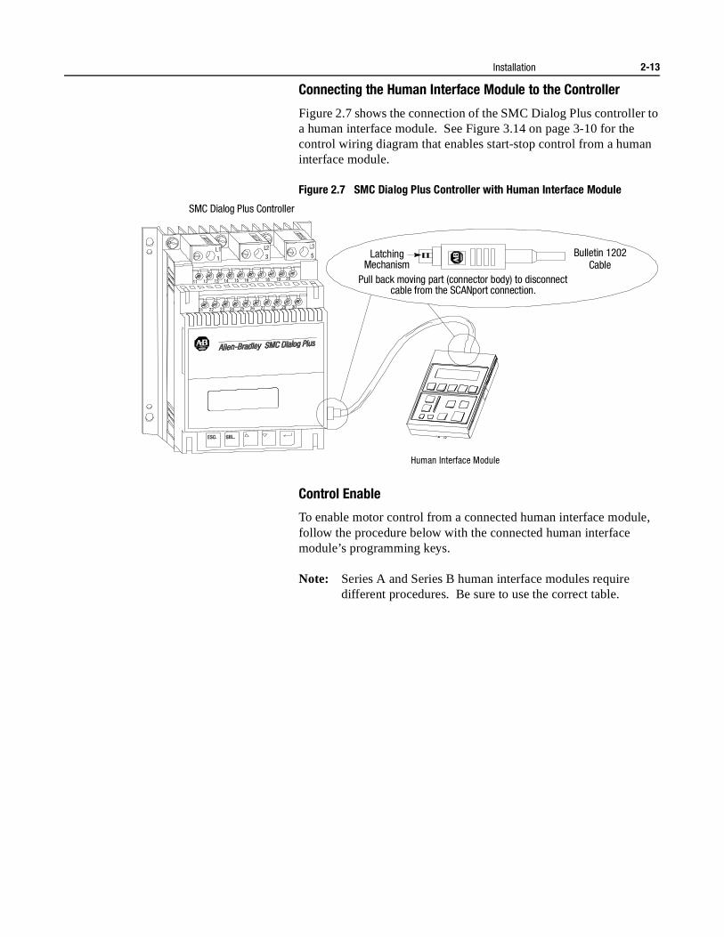
Connecting the Human Interface Module to the Controller
Figure 2.7 shows the connection of the SMC Dialog Plus controller to a human interface module. See Figure 3.14 on page 3-10 for the control wiring diagram that enables start-stop control from a human interface module.
Figure 2.7 SMC Dialog Plus Controller with Human Interface Module
Control Enable
To enable motor control from a connected human interface module, follow the procedure below with the connected human interface module’s programming keys.
Note: Series A and Series B human interface modules require different procedures. Be sure to use the correct table.
Human Interface Module
SMC Dialog Plus Controller
Pull back moving part (connector body) to disconnect cable from the SCANport connection.
Bulletin 1202Cable
Latching Mechanism
1
11
21
12
22
13
23
14
24
15
25
16
26
17
27
18
28
19
29
20
30
3 5
2-14 Installation
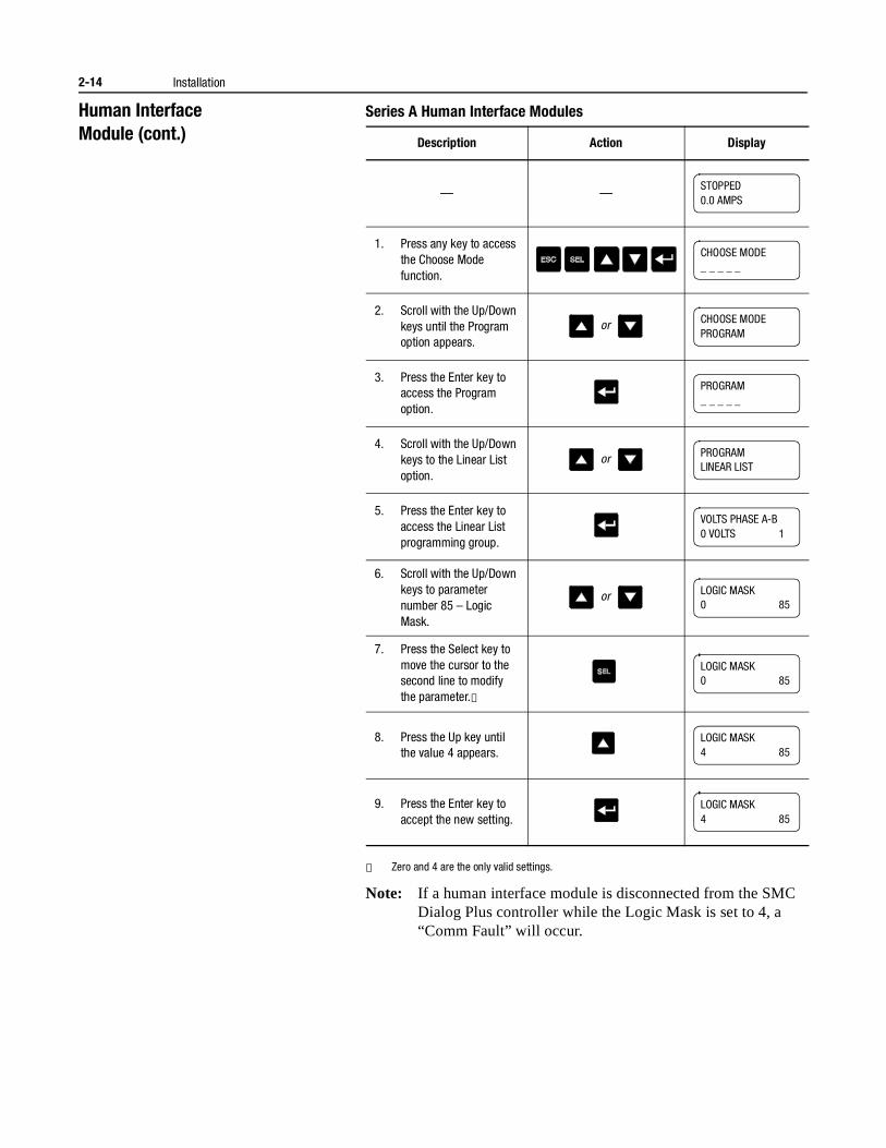
Human InterfaceModule (cont.)
Series A Human Interface Modules
① Zero and 4 are the only valid settings.
Note: If a human interface module is disconnected from the SMC Dialog Plus controller while the Logic Mask is set to 4, a “Comm Fault” will occur.
Description Action Display
— —
1. Press any key to access the Choose Mode function.
2. Scroll with the Up/Down keys until the Program option appears.
3. Press the Enter key to access the Program option.
4. Scroll with the Up/Down keys to the Linear List option.
5. Press the Enter key to access the Linear List programming group.
6. Scroll with the Up/Down keys to parameter number 85 – Logic Mask.
7. Press the Select key to move the cursor to the second line to modify the parameter.①
8. Press the Up key until the value 4 appears.
9. Press the Enter key to accept the new setting.
STOPPED0.0 AMPS
CHOOSE MODE_ _ _ _ _
or CHOOSE MODEPROGRAM
PROGRAM_ _ _ _ _
or PROGRAMLINEAR LIST
VOLTS PHASE A-B0 VOLTS 1
or LOGIC MASK0 85
LOGIC MASK0 85
LOGIC MASK4 85
LOGIC MASK4 85
Installation 2-15
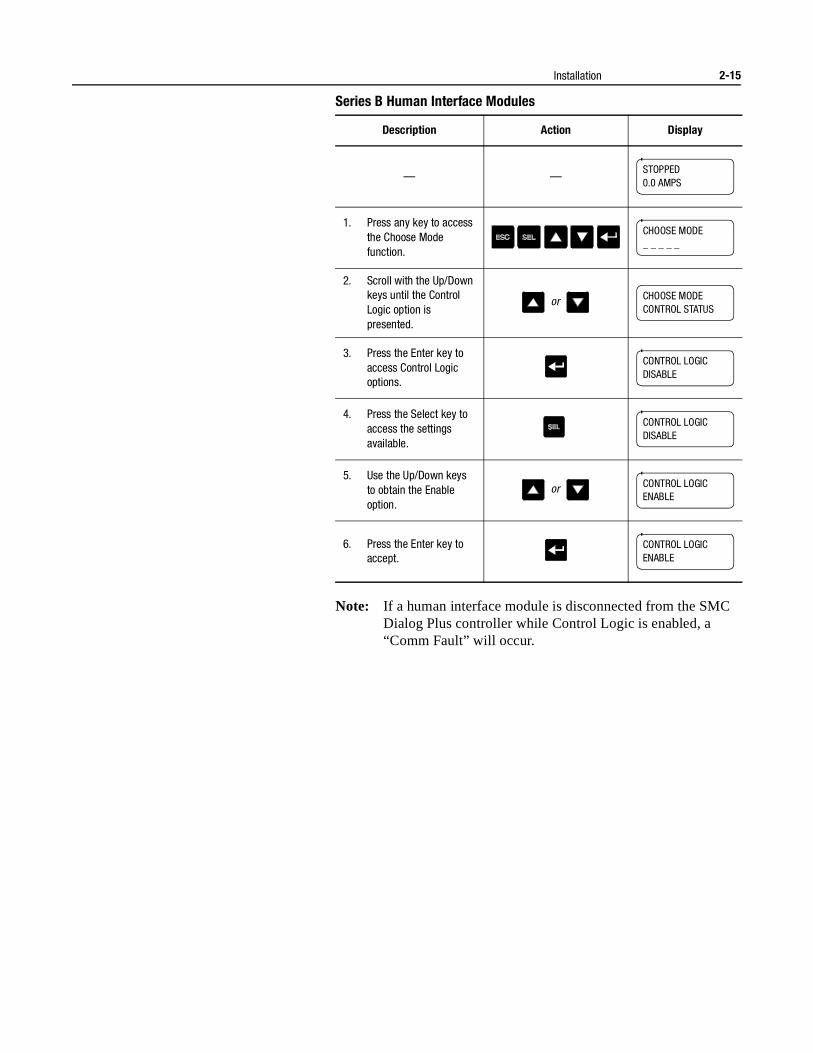
Series B Human Interface Modules
Note: If a human interface module is disconnected from the SMC Dialog Plus controller while Control Logic is enabled, a “Comm Fault” will occur.
Description Action Display
— —
1. Press any key to access the Choose Mode function.
2. Scroll with the Up/Down keys until the Control Logic option is presented.
3. Press the Enter key to access Control Logic options.
4. Press the Select key to access the settings available.
5. Use the Up/Down keys to obtain the Enable option.
6. Press the Enter key to accept.
STOPPED0.0 AMPS
CHOOSE MODE_ _ _ _ _
or CHOOSE MODECONTROL STATUS
CONTROL LOGICDISABLE
CONTROL LOGICDISABLE
or CONTROL LOGICENABLE
CONTROL LOGICENABLE
2-16 Installation
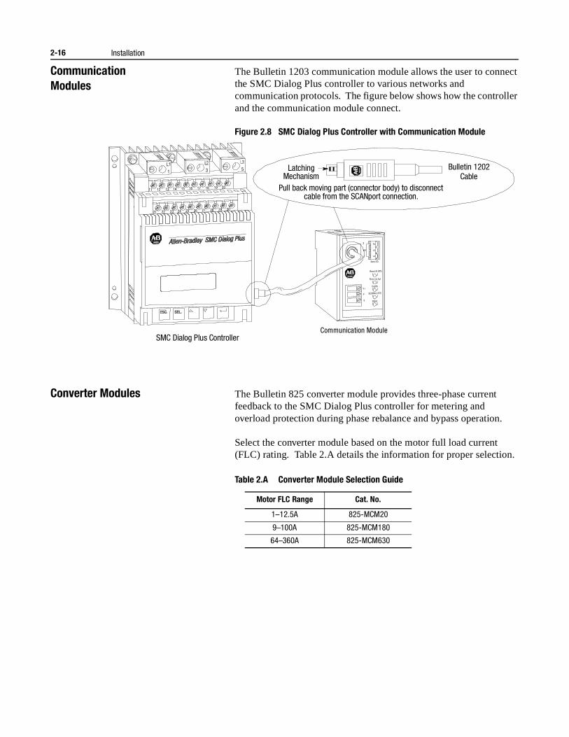
CommunicationModules
The Bulletin 1203 communication module allows the user to connect the SMC Dialog Plus controller to various networks and communication protocols. The figure below shows how the controller and the communication module connect.
Figure 2.8 SMC Dialog Plus Controller with Communication Module
Converter Modules The Bulletin 825 converter module provides three-phase current feedback to the SMC Dialog Plus controller for metering and overload protection during phase rebalance and bypass operation.
Select the converter module based on the motor full load current (FLC) rating. Table 2.A details the information for proper selection.
Table 2.A Converter Module Selection Guide
Communication Module SMC Dialog Plus Controller
Pull back moving part (connector body) to disconnect cable from the SCANport connection.
Bulletin 1202Cable
Latching Mechanism
V+
V-
G
1
11
21
12
22
13
23
14
24
15
25
16
26
17
27
18
28
19
29
20
30
3 5
Motor FLC Range Cat. No.
1–12.5A 825-MCM20
9–100A 825-MCM180
64–360A 825-MCM630
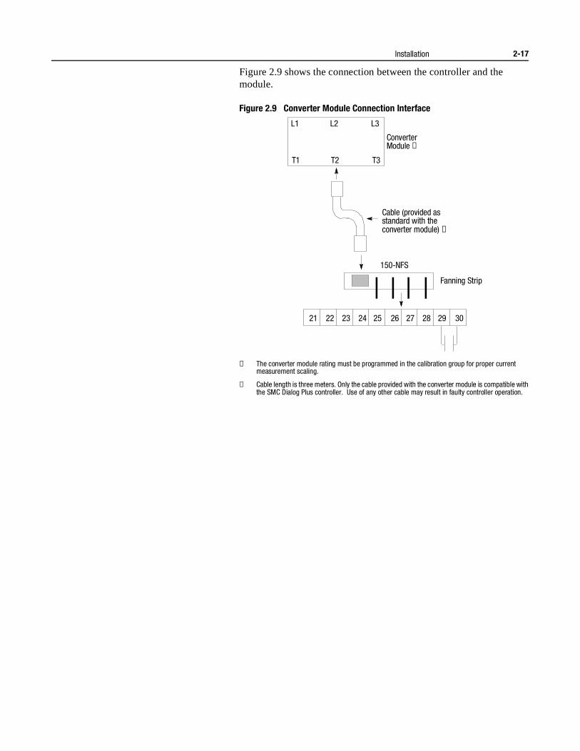
Installation 2-17
Figure 2.9 shows the connection between the controller and the module.
Figure 2.9 Converter Module Connection Interface
① The converter module rating must be programmed in the calibration group for proper current measurement scaling.
② Cable length is three meters. Only the cable provided with the converter module is compatible with the SMC Dialog Plus controller. Use of any other cable may result in faulty controller operation.
T1 T2 T3
L1 L2 L3
150-NFS
21 22 23 24 25 26 27 28 29 30
Converter Module ➀
Cable (provided as standard with the converter module) ➁
Fanning Strip
2-18 Installation
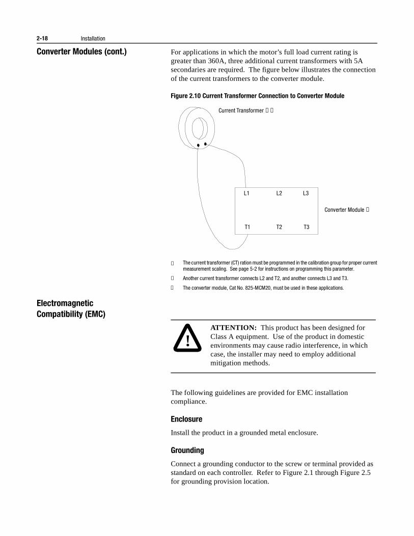
Converter Modules (cont.) For applications in which the motor’s full load current rating is greater than 360A, three additional current transformers with 5A secondaries are required. The figure below illustrates the connection of the current transformers to the converter module.
Figure 2.10 Current Transformer Connection to Converter Module
① The current transformer (CT) ration must be programmed in the calibration group for proper current measurement scaling. See page 5-2 for instructions on programming this parameter.
② Another current transformer connects L2 and T2, and another connects L3 and T3.
③ The converter module, Cat No. 825-MCM20, must be used in these applications.
ElectromagneticCompatibility (EMC)
The following guidelines are provided for EMC installation compliance.
Enclosure
Install the product in a grounded metal enclosure.
Grounding
Connect a grounding conductor to the screw or terminal provided as standard on each controller. Refer to Figure 2.1 through Figure 2.5 for grounding provision location.
Current Transformer ➀➁
L1 L3
T1 T3
L2
T2
Converter Module ➂
!
.
ATTENTION: This product has been designed for Class A equipment. Use of the product in domestic environments may cause radio interference, in which case, the installer may need to employ additional mitigation methods.
Installation 2-19
Wiring
Wire in an industrial control application can be divided into three groups: power, control, and signal. The following recommendations for physical separation between these groups is provided to reduce the coupling effect.
• Different wire groups should cross at 90° inside an enclosure.
• Minimum spacing between different wire groups in the same tray should be six inches (16 cm).
• Wire runs outside an enclosure should be run in conduit or have shielding/armor with equivalent attenuation.
• Different wire groups should be run in separate conduits.
• Minimum spacing between conduits containing different wire groups should be three inches (8 cm).
Accessory Requirements
When connection of the Bulletin 825 converter module or Bulletin 1202 communication cable is required, a ferrite core suppressor (Fair-Rite PN 2643802702 or equal) should be used in conjunction. Mount the suppressor as close to the controller as practical, wrapping the cable twice through the suppressor.

2-20 Installation
Chapter 3
Wiring
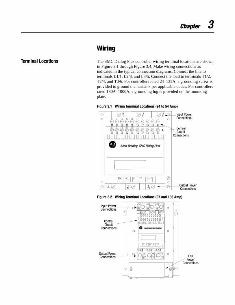
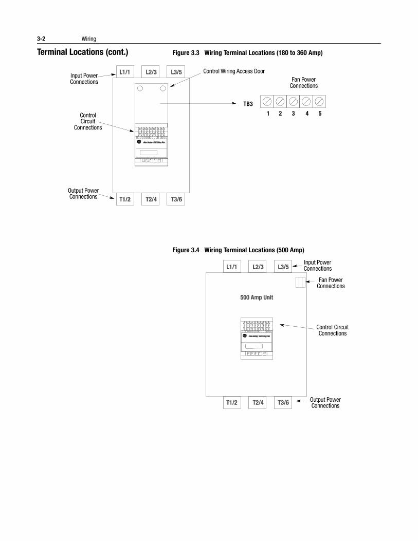
Terminal Locations The SMC Dialog Plus controller wiring terminal locations are shown in Figure 3.1 through Figure 3.4. Make wiring connections as indicated in the typical connection diagrams. Connect the line to terminals L1/1, L2/3, and L3/5. Connect the load to terminals T1/2, T2/4, and T3/6. For controllers rated 24–135A, a grounding screw is provided to ground the heatsink per applicable codes. For controllers rated 180A–1000A, a grounding lug is provided on the mounting plate.
Figure 3.1 Wiring Terminal Locations (24 to 54 Amp)
Figure 3.2 Wiring Terminal Locations (97 and 135 Amp)
Input Power Connections
Control Circuit
Connections
Output Power Connections
L11
2T1
4T2
6T3
ESC. SEL.
11
21
13
23
12
22
14
24
15
25
16
26
17
27
18
28
19
29
20
30
L23
L35
Input Power Connections
Control Circuit
Connections
Output Power Connections Fan
Power Connections
3-2 Wiring
Terminal Locations (cont.) Figure 3.3 Wiring Terminal Locations (180 to 360 Amp)
Figure 3.4 Wiring Terminal Locations (500 Amp)
Control Wiring Access Door Input Power Connections
Control Circuit
Connections
Output Power Connections
Fan Power Connections
TB3
1 2 3 4 5
Input Power Connections
Control Circuit Connections
Output Power Connections
Fan Power Connections
Wiring 3-3
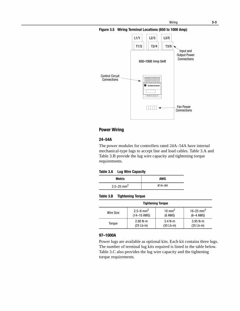
Figure 3.5 Wiring Terminal Locations (650 to 1000 Amp)
Power Wiring
24–54AThe power modules for controllers rated 24A–54A have internal mechanical-type lugs to accept line and load cables. Table 3.A and Table 3.B provide the lug wire capacity and tightening torque requirements.
Table 3.A Lug Wire Capacity
Table 3.B Tightening Torque
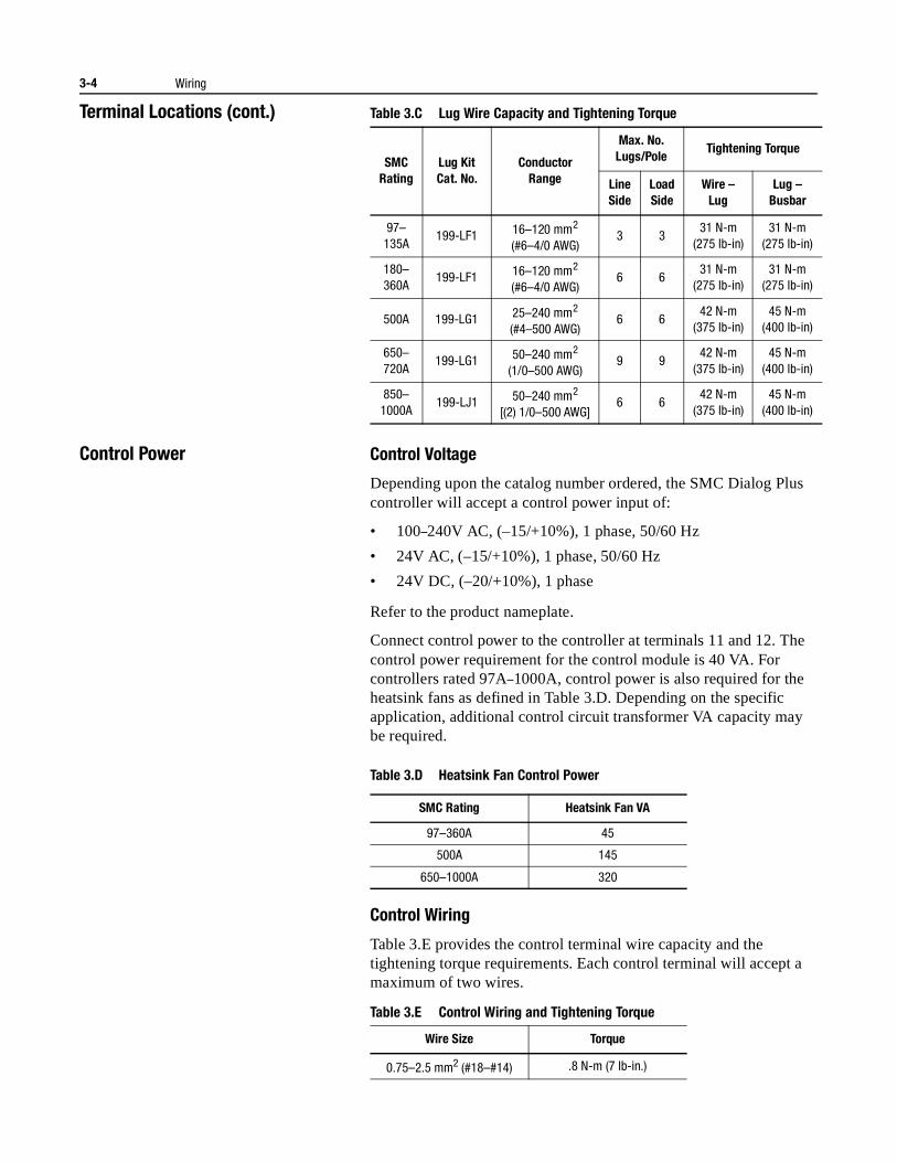
97–1000APower lugs are available as optional kits. Each kit contains three lugs. The number of terminal lug kits required is listed in the table below. Table 3.C also provides the lug wire capacity and the tightening torque requirements.
Input andOutput Power Connections
Control Circuit Connections
Fan Power Connections
Metric AWG
2.5–25 mm2 #14–#4
Tightening Torque
Wire Size 2.5–6 mm2
(14–10 AWG)10 mm2
(8 AWG)16–25 mm2
(6–4 AWG)
Torque2.80 N-m(25 Lb-in)
3.4 N-m(30 Lb-in)
3.95 N-m(35 Lb-in)
3-4 Wiring
Terminal Locations (cont.) Table 3.C Lug Wire Capacity and Tightening Torque
Control Power Control Voltage
Depending upon the catalog number ordered, the SMC Dialog Plus controller will accept a control power input of:
• 100–240V AC, (–15/+10%), 1 phase, 50/60 Hz
• 24V AC, (–15/+10%), 1 phase, 50/60 Hz
• 24V DC, (–20/+10%), 1 phase
Refer to the product nameplate.
Connect control power to the controller at terminals 11 and 12. The control power requirement for the control module is 40 VA. For controllers rated 97A–1000A, control power is also required for the heatsink fans as defined in Table 3.D. Depending on the specific application, additional control circuit transformer VA capacity may be required.
Table 3.D Heatsink Fan Control Power
Control Wiring
Table 3.E provides the control terminal wire capacity and the tightening torque requirements. Each control terminal will accept a maximum of two wires.
Table 3.E Control Wiring and Tightening Torque
SMCRating
Lug KitCat. No.
ConductorRange
Max. No. Lugs/Pole
Tightening Torque
LineSide
LoadSide
Wire –Lug
Lug –Busbar
97–135A
199-LF1 16–120 mm2
(#6–4/0 AWG)3 3
31 N-m(275 lb-in)
31 N-m(275 lb-in)
180–360A
199-LF1 16–120 mm2
(#6–4/0 AWG)6 6
31 N-m(275 lb-in)
31 N-m(275 lb-in)
500A 199-LG1 25–240 mm2
(#4–500 AWG)6 6
42 N-m(375 lb-in)
45 N-m(400 lb-in)
650–720A
199-LG1 50–240 mm2
(1/0–500 AWG)9 9
42 N-m(375 lb-in)
45 N-m(400 lb-in)
850–1000A
199-LJ1 50–240 mm2
[(2) 1/0–500 AWG]6 6
42 N-m(375 lb-in)
45 N-m(400 lb-in)
SMC Rating Heatsink Fan VA
97–360A 45
500A 145
650–1000A 320
Wire Size Torque
0.75–2.5 mm2 (#18–#14) .8 N-m (7 lb-in.)
Wiring 3-5
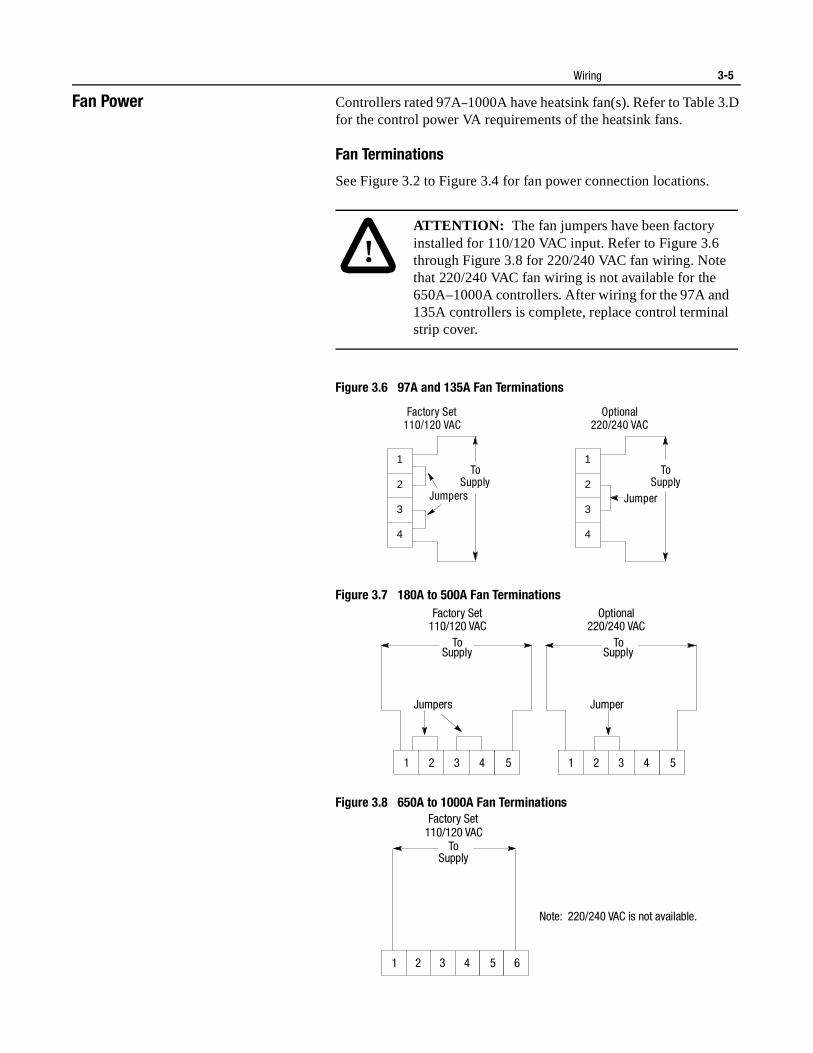
Fan Power Controllers rated 97A–1000A have heatsink fan(s). Refer to Table 3.D for the control power VA requirements of the heatsink fans.
Fan Terminations
See Figure 3.2 to Figure 3.4 for fan power connection locations.
Figure 3.6 97A and 135A Fan Terminations
Figure 3.7 180A to 500A Fan Terminations
Figure 3.8 650A to 1000A Fan Terminations
!ATTENTION: The fan jumpers have been factory installed for 110/120 VAC input. Refer to Figure 3.6 through Figure 3.8 for 220/240 VAC fan wiring. Note that 220/240 VAC fan wiring is not available for the 650A–1000A controllers. After wiring for the 97A and 135A controllers is complete, replace control terminal strip cover.
Factory Set 110/120 VAC
Optional 220/240 VAC
Jumpers
To Supply
Jumper
To Supply
1
2
3
4
1
2
3
4
Factory Set 110/120 VAC
Optional 220/240 VAC
To Supply
To Supply
Jumpers Jumper
1 2 3 4 5 1 2 3 4 5
Factory Set 110/120 VAC
To Supply
1 2 3 4 5 6
Note: 220/240 VAC is not available.
3-6 Wiring
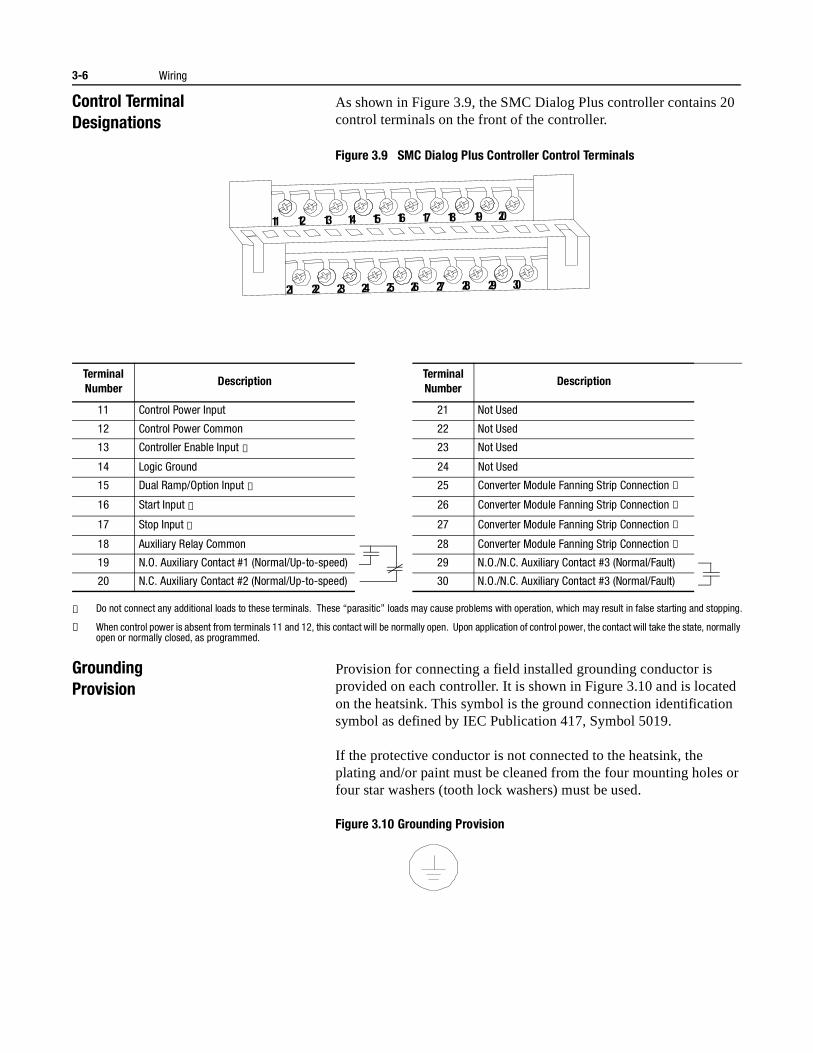
Control TerminalDesignations
As shown in Figure 3.9, the SMC Dialog Plus controller contains 20 control terminals on the front of the controller.
Figure 3.9 SMC Dialog Plus Controller Control Terminals
① Do not connect any additional loads to these terminals. These “parasitic” loads may cause problems with operation, which may result in false starting and stopping.
② When control power is absent from terminals 11 and 12, this contact will be normally open. Upon application of control power, the contact will take the state, normally open or normally closed, as programmed.
GroundingProvision
Provision for connecting a field installed grounding conductor is provided on each controller. It is shown in Figure 3.10 and is located on the heatsink. This symbol is the ground connection identification symbol as defined by IEC Publication 417, Symbol 5019.
If the protective conductor is not connected to the heatsink, the plating and/or paint must be cleaned from the four mounting holes or four star washers (tooth lock washers) must be used.
Figure 3.10 Grounding Provision
Terminal Number
DescriptionTerminal Number
Description
11 Control Power Input 21 Not Used
12 Control Power Common 22 Not Used
13 Controller Enable Input ① 23 Not Used
14 Logic Ground 24 Not Used
15 Dual Ramp/Option Input ① 25 Converter Module Fanning Strip Connection ②
16 Start Input ① 26 Converter Module Fanning Strip Connection ②
17 Stop Input ① 27 Converter Module Fanning Strip Connection ②
18 Auxiliary Relay Common 28 Converter Module Fanning Strip Connection ②
19 N.O. Auxiliary Contact #1 (Normal/Up-to-speed) 29 N.O./N.C. Auxiliary Contact #3 (Normal/Fault)
20 N.C. Auxiliary Contact #2 (Normal/Up-to-speed) 30 N.O./N.C. Auxiliary Contact #3 (Normal/Fault)
11
21
12
22
13
23
14
24
15
25
16
26
17
27
18
28
19
29
20
30
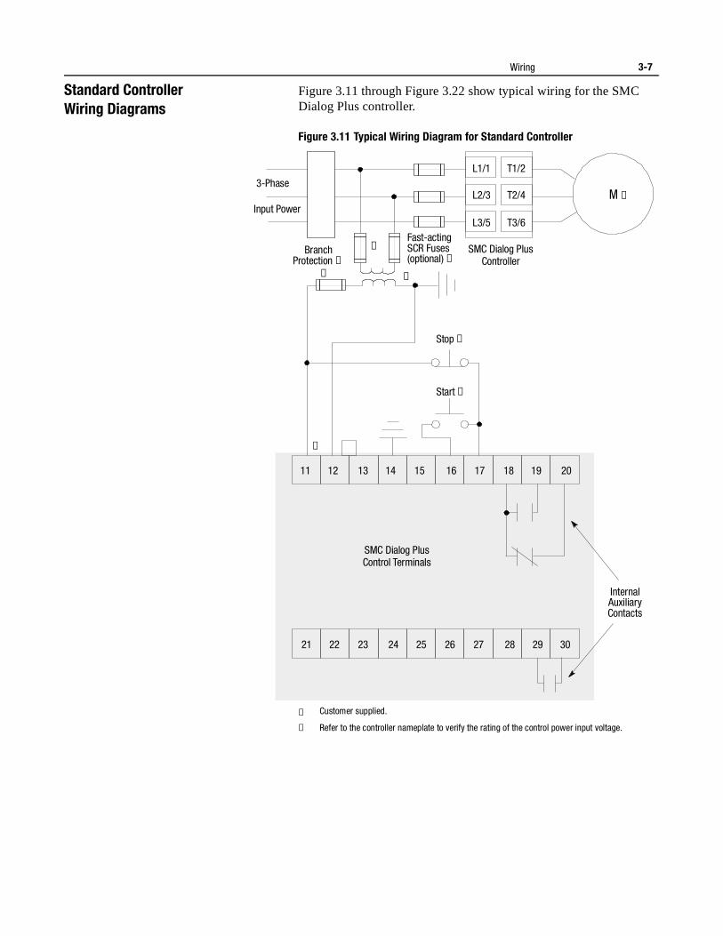
Wiring 3-7
Standard ControllerWiring Diagrams
Figure 3.11 through Figure 3.22 show typical wiring for the SMC Dialog Plus controller.
Figure 3.11 Typical Wiring Diagram for Standard Controller
① Customer supplied.
② Refer to the controller nameplate to verify the rating of the control power input voltage.
Stop ➀
11 12 13 14 15 16 17 18 19 20
21 22 23 24 25 26 27 28 29 30
Start ➀
Internal Auxiliary Contacts
SMC Dialog PlusControl Terminals
3-Phase
Input Power
Branch Protection ➀
Fast-acting SCR Fuses (optional) ➀
SMC Dialog PlusController
M ➀
L1/1
L2/3
L3/5
T1/2
T2/4
T3/6
➀
➀ ➀
➁
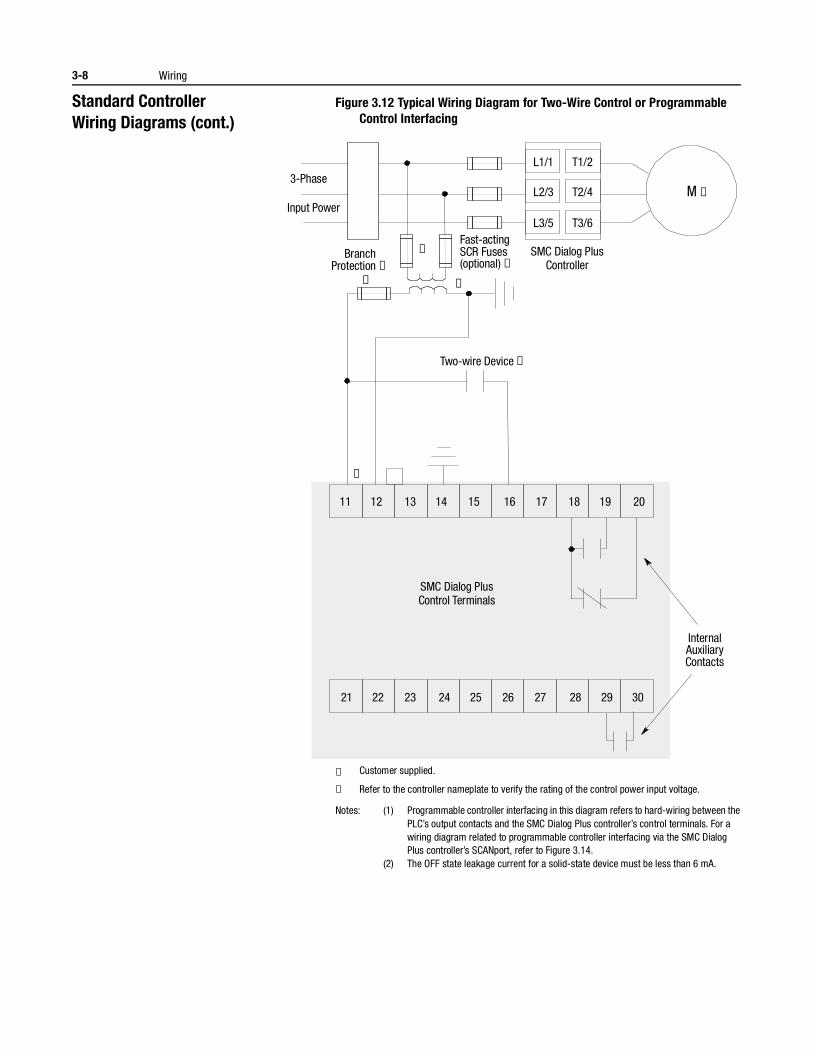
3-8 Wiring
Standard ControllerWiring Diagrams (cont.)
Figure 3.12 Typical Wiring Diagram for Two-Wire Control or Programmable Control Interfacing
① Customer supplied.
② Refer to the controller nameplate to verify the rating of the control power input voltage.
Notes: (1) Programmable controller interfacing in this diagram refers to hard-wiring between the PLC’s output contacts and the SMC Dialog Plus controller’s control terminals. For a wiring diagram related to programmable controller interfacing via the SMC Dialog Plus controller’s SCANport, refer to Figure 3.14.
(2) The OFF state leakage current for a solid-state device must be less than 6 mA.
Two-wire Device ➀
11 12 13 14 15 16 17 18 19 20
21 22 23 24 25 26 27 28 29 30
Internal Auxiliary Contacts
3-Phase
Input Power
Branch Protection ➀
Fast-acting SCR Fuses (optional) ➀
SMC Dialog PlusController
M ➀
L1/1
L2/3
L3/5
T1/2
T2/4
T3/6
➀
➀ ➀
➁
SMC Dialog PlusControl Terminals
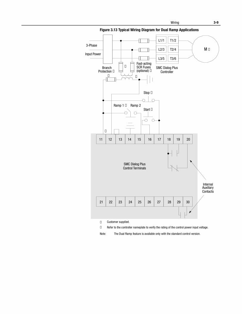
Wiring 3-9
Figure 3.13 Typical Wiring Diagram for Dual Ramp Applications
① Customer supplied.
② Refer to the controller nameplate to verify the rating of the control power input voltage.
Note: The Dual Ramp feature is available only with the standard control version.
Stop ➀
11 12 13 14 15 16 17 18 19 20
21 22 23 24 25 26 27 28 29 30
Start ➀Ramp 1 ➀ Ramp 2
Internal Auxiliary Contacts
3-Phase
Input Power
Branch Protection ➀
Fast-acting SCR Fuses (optional) ➀
SMC Dialog PlusController
M ➀
L1/1
L2/3
L3/5
T1/2
T2/4
T3/6
➀
➀ ➀
➁
SMC Dialog PlusControl Terminals
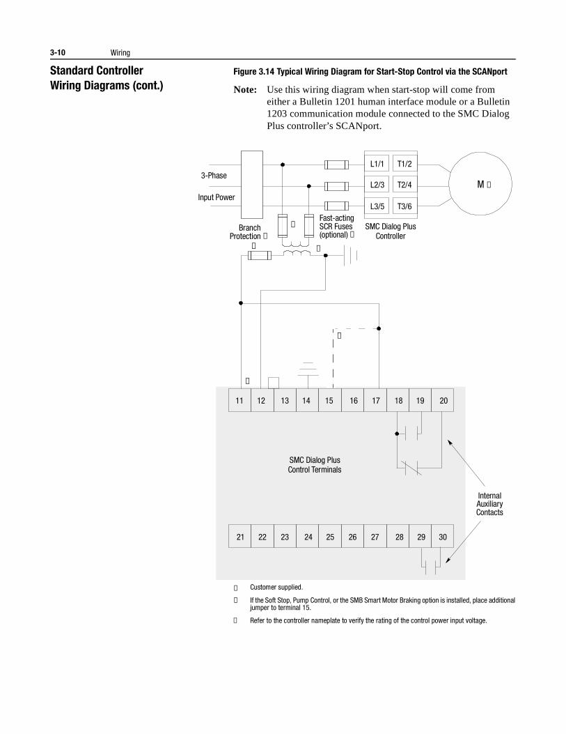
3-10 Wiring
Standard ControllerWiring Diagrams (cont.)
Figure 3.14 Typical Wiring Diagram for Start-Stop Control via the SCANport
Note: Use this wiring diagram when start-stop will come from either a Bulletin 1201 human interface module or a Bulletin 1203 communication module connected to the SMC Dialog Plus controller’s SCANport.
① Customer supplied.
② If the Soft Stop, Pump Control, or the SMB Smart Motor Braking option is installed, place additional jumper to terminal 15.
③ Refer to the controller nameplate to verify the rating of the control power input voltage.
11 12 13 14 15 16 17 18 19 20
21 22 23 24 25 26 27 28 29 30
Internal Auxiliary Contacts
3-Phase
Input Power
Branch Protection ➀
Fast-acting SCR Fuses (optional) ➀
M ➀
L1/1
L2/3
L3/5
T1/2
T2/4
T3/6
➀
➀ ➀
➁
➂
SMC Dialog PlusController
SMC Dialog PlusControl Terminals
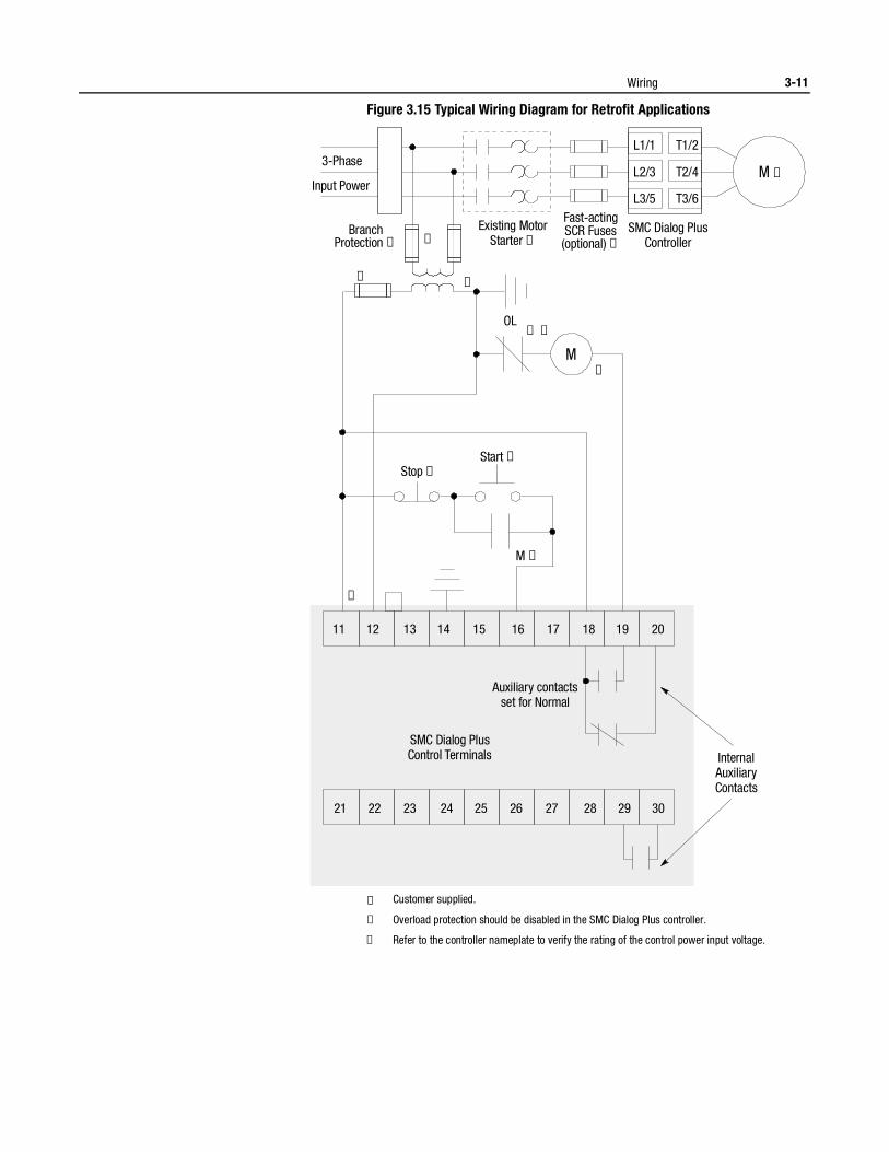
Wiring 3-11
Figure 3.15 Typical Wiring Diagram for Retrofit Applications
① Customer supplied.
② Overload protection should be disabled in the SMC Dialog Plus controller.
③ Refer to the controller nameplate to verify the rating of the control power input voltage.
Stop ➀
M ➀
Start ➀
3-Phase
Input Power
Branch Protection ➀
Fast-acting SCR Fuses (optional) ➀
M ➀
M
➀
➀
➀
➀ ➁
➀
➂
L1/1
L2/3
L3/5
OL
T1/2
T2/4
T3/6
11 12 13 14 15 16 17 18 19 20
21 22 23 24 25 26 27 28 29 30
Internal AuxiliaryContacts
Auxiliary contactsset for Normal
SMC Dialog PlusController
SMC Dialog PlusControl Terminals
Existing MotorStarter ➀
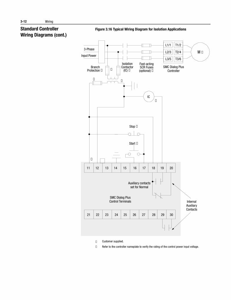
3-12 Wiring
Standard ControllerWiring Diagrams (cont.)
Figure 3.16 Typical Wiring Diagram for Isolation Applications
① Customer supplied.
② Refer to the controller nameplate to verify the rating of the control power input voltage.
Stop ➀
Start ➀
3-Phase
Input Power
Branch Protection ➀
Fast-acting SCR Fuses (optional) ➀
IsolationContactor
(IC) ➀
M ➀
IC
➀
➀
➀ ➀
➁
L1/1
L2/3
L3/5
T1/2
T2/4
T3/6
11 12 13 14 15 16 17 18 19 20
21 22 23 24 25 26 27 28 29 30
Internal AuxiliaryContacts
Auxiliary contactsset for Normal
SMC Dialog PlusController
SMC Dialog PlusControl Terminals
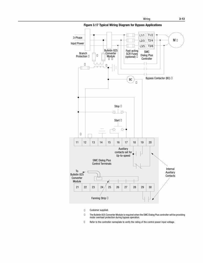
Wiring 3-13
Figure 3.17 Typical Wiring Diagram for Bypass Applications
① Customer supplied.
② The Bulletin 825 Converter Module is required when the SMC Dialog Plus controller will be providing motor overload protection during bypass operation.
③ Refer to the controller nameplate to verify the rating of the control power input voltage.
Stop ➀
Start ➀
3-Phase
Input Power
Branch
Bypass Contactor (BC) ➀
Protection ➀
Fast-acting SCR Fuses (optional) ➀
Bulletin 825ConverterModule
➀ ➁
M ➀
BC
➀
➀
➀ ➀
➂
L1/1
L2/3
L3/5
T1/2
T2/4
T3/6
11 12 13 14 15 16 17 18 19 20
21 22 23 24 25 26 27 28 29 30
Internal AuxiliaryContacts
Fanning Strip ➀
ToBulletin 825ConverterModule
Auxiliarycontacts set for
Up-to-speed
SMCDialog PlusController
SMC Dialog PlusControl Terminals
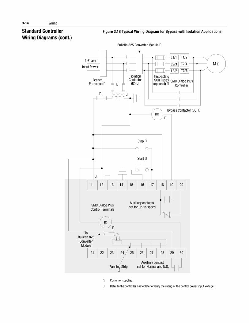
3-14 Wiring
Standard ControllerWiring Diagrams (cont.)
Figure 3.18 Typical Wiring Diagram for Bypass with Isolation Applications
① Customer supplied.
② Refer to the controller nameplate to verify the rating of the control power input voltage.
Stop ➀
Start ➀
Bypass Contactor (BC) ➀
➁
3-Phase
Input Power
Branch Protection ➀
Fast-acting SCR Fuses (optional) ➀
Bulletin 825 Converter Module ➀
IsolationContactor
(IC) ➀
M ➀
BC
➀
➀
➀
➀
➀
L1/1
L2/3
L3/5
T1/2
T2/4
T3/6
11 12 13 14 15 16 17 18 19 20
21 22 23 24 25 26 27 28 29 30
IC
Fanning Strip ➀
ToBulletin 825ConverterModule
Auxiliary contacts set for Up-to-speed
Auxiliary contact set for Normal and N.O.
SMC Dialog PlusController
SMC Dialog PlusControl Terminals
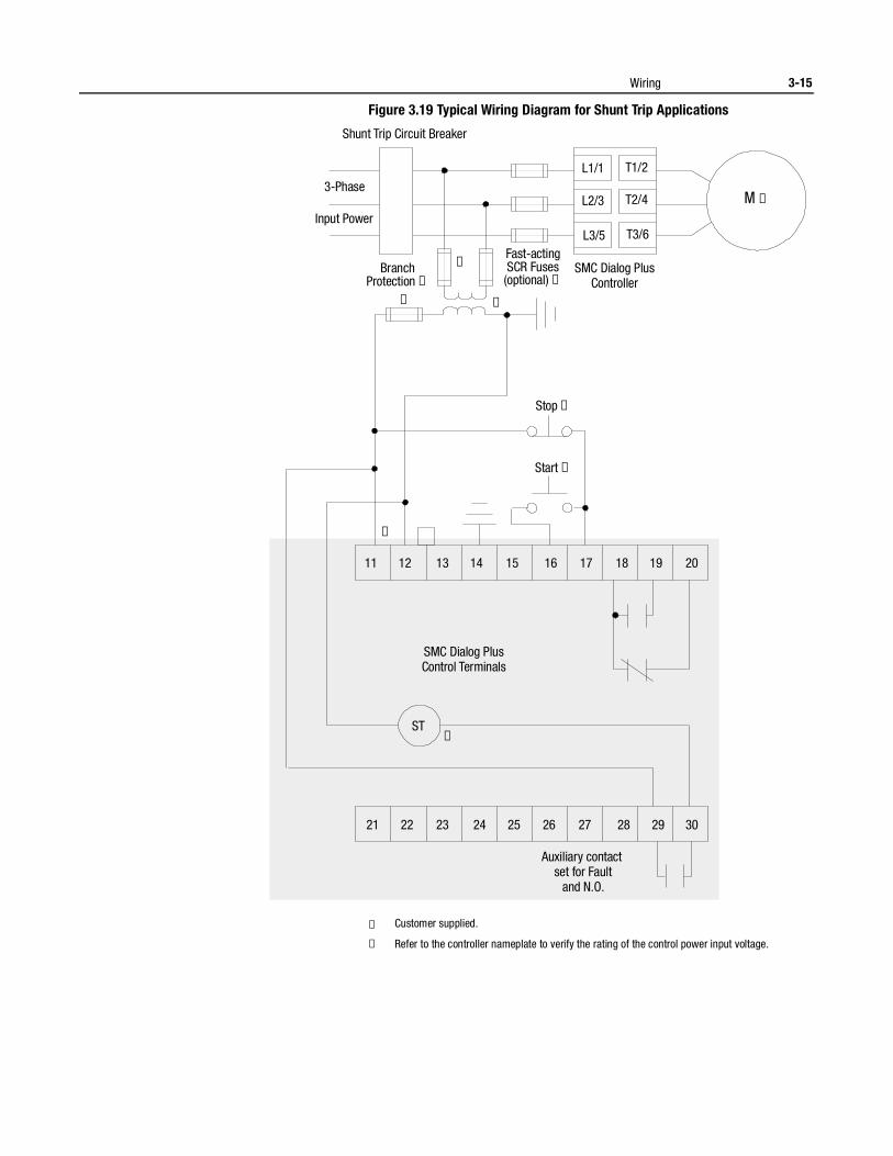
Wiring 3-15
Figure 3.19 Typical Wiring Diagram for Shunt Trip Applications
① Customer supplied.
② Refer to the controller nameplate to verify the rating of the control power input voltage.
Stop ➀
Start ➀
➁
3-Phase
Shunt Trip Circuit Breaker
Input Power
Branch Protection ➀
Fast-acting SCR Fuses (optional) ➀
M ➀
➀
➀ ➀
L1/1
L2/3
L3/5
T1/2
T2/4
T3/6
➀
11 12 13 14 15 16 17 18 19 20
21 22 23 24 25 26 27 28 29 30
ST
Auxiliary contact set for Fault
and N.O.
SMC Dialog PlusController
SMC Dialog PlusControl Terminals

3-16 Wiring
Standard ControllerWiring Diagrams (cont.)
Figure 3.20 Typical Wiring Diagram for Single Speed Reversing Applications
① Customer supplied.
② Refer to the controller nameplate to verify the rating of the control power input rating.
Notes: (1) Minimum transition time for reversing direction is 1/2 second.(2) Phase Reversal protection must be disabled in reversing applications.
Stop ➀
OFF ➀
FOR REVF
F
FR
R
R
➁
3-Phase
Input Power
Branch Protection ➀
Reversing Contactors ➀
Fast-acting SCR Fuses (optional) ➀
Bulletin 825Coverter
Module(optional)
➀
M ➀
➀ ➀
➀
F
R
L1/1
L2/3
L3/5
T1/2
T2/4
T3/6
➀
➀
➀
➀
➀
➀
11 12 13 14 15 16 17 18 19 20
21 22 23 24 25 26 27 28 29 30
InternalAuxiliaryContacts
SMC Dialog PlusController
SMC Dialog PlusControl Terminals
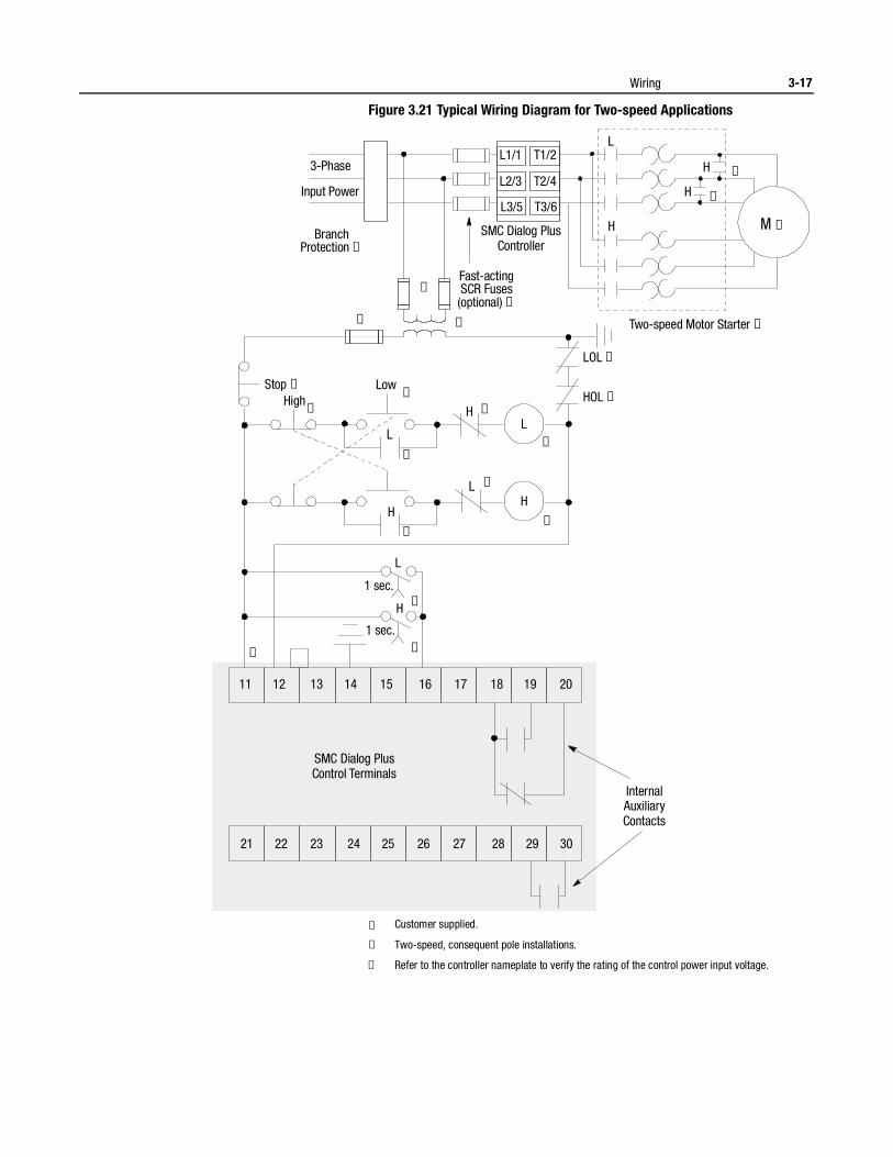
Wiring 3-17
Figure 3.21 Typical Wiring Diagram for Two-speed Applications
① Customer supplied.
② Two-speed, consequent pole installations.
③ Refer to the controller nameplate to verify the rating of the control power input voltage.
3-Phase
Input Power
Branch Protection ➀
Two-speed Motor Starter ➀
Fast-acting SCR Fuses (optional) ➀
M ➀
➀ ➀
➀
L1/1
L2/3
L3/5
T1/2
T2/4
T3/6
L
H
H
H
➁
➁
Stop ➀
High Low
LOL ➀
HOL ➀H
L
L
1 sec.
1 sec.
HL
H
H
L
➂
➀
➀
➀➀
➀
➀
➀
➀
➀
➀
11 12 13 14 15 16 17 18 19 20
21 22 23 24 25 26 27 28 29 30
InternalAuxiliaryContacts
SMC Dialog PlusController
SMC Dialog PlusControl Terminals
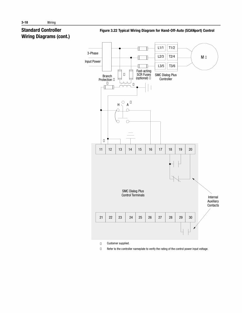
3-18 Wiring
Standard ControllerWiring Diagrams (cont.)
Figure 3.22 Typical Wiring Diagram for Hand-Off-Auto (SCANport) Control
① Customer supplied.
② Refer to the controller nameplate to verify the rating of the control power input voltage.
H A
3-Phase
Input Power
Branch Protection ➀
Fast-acting SCR Fuses (optional) ➀
M ➀
➀
➀
➀
➀
L1/1
L2/3
L3/5
T1/2
T2/4
T3/6
➁
11 12 13 14 15 16 17 18 19 20
21 22 23 24 25 26 27 28 29 30
InternalAuxiliaryContacts
SMC Dialog PlusController
SMC Dialog PlusControl Terminals
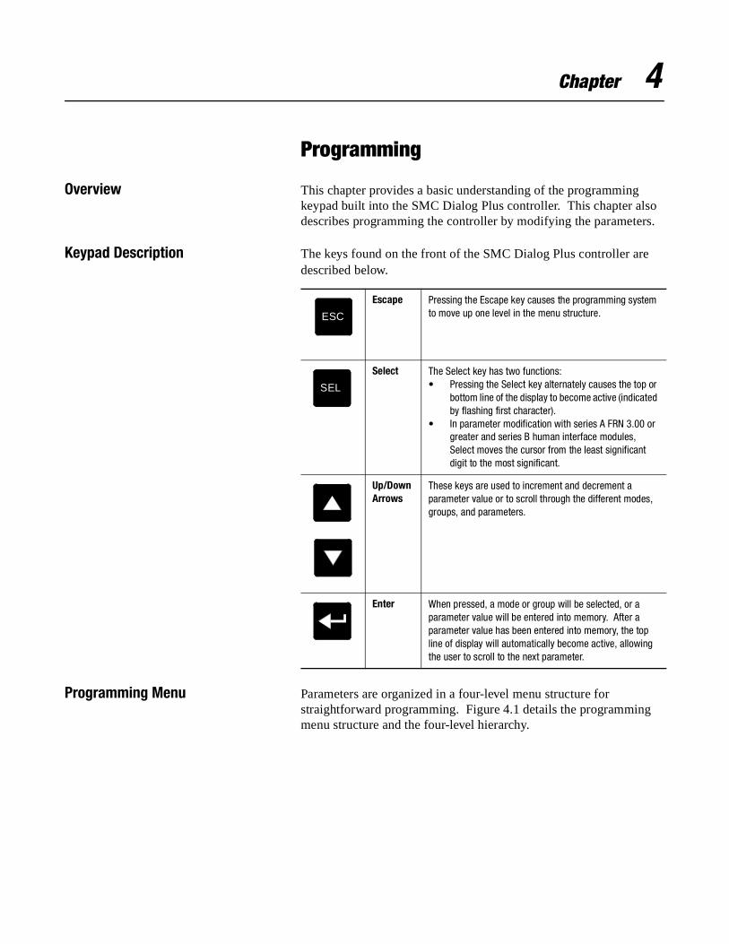
Chapter 4
Programming
Overview This chapter provides a basic understanding of the programming keypad built into the SMC Dialog Plus controller. This chapter also describes programming the controller by modifying the parameters.
Keypad Description The keys found on the front of the SMC Dialog Plus controller are described below.
Programming Menu Parameters are organized in a four-level menu structure for straightforward programming. Figure 4.1 details the programming menu structure and the four-level hierarchy.
Escape Pressing the Escape key causes the programming system to move up one level in the menu structure.
Select The Select key has two functions:• Pressing the Select key alternately causes the top or
bottom line of the display to become active (indicated by flashing first character).
• In parameter modification with series A FRN 3.00 or greater and series B human interface modules, Select moves the cursor from the least significant digit to the most significant.
Up/Down Arrows
These keys are used to increment and decrement a parameter value or to scroll through the different modes, groups, and parameters.
Enter When pressed, a mode or group will be selected, or a parameter value will be entered into memory. After a parameter value has been entered into memory, the top line of display will automatically become active, allowing the user to scroll to the next parameter.
ESC
SEL
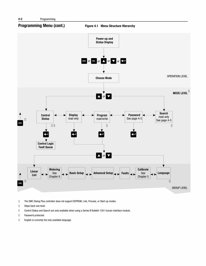
4-2 Programming
Programming Menu (cont.) Figure 4.1 Menu Structure Hierarchy
① The SMC Dialog Plus controller does not support EEPROM, Link, Process, or Start-up modes.
② Steps back one level.
③ Control Status and Search are only available when using a Series B Bulletin 1201 human interface module.
④ Password protected.
⑤ English is currently the only available language.
Power-up andStatus Display
Choose Mode
ControlStatus
Control LogicFault Queue
LinearList
Basic Setup Advanced Setup Faults Language
Displayread only
MeteringSee
Chapter 6
CalibrateSee
Chapter 5
Programread/write
PasswordSee page 4-5
Searchread only
See page 4-5
or or or
or
or
or
OPERATION LEVEL
MODE LEVELMODE LEVEL
GROUP LEVEL
➀
➂➃➂➃
➁
➁
⑤
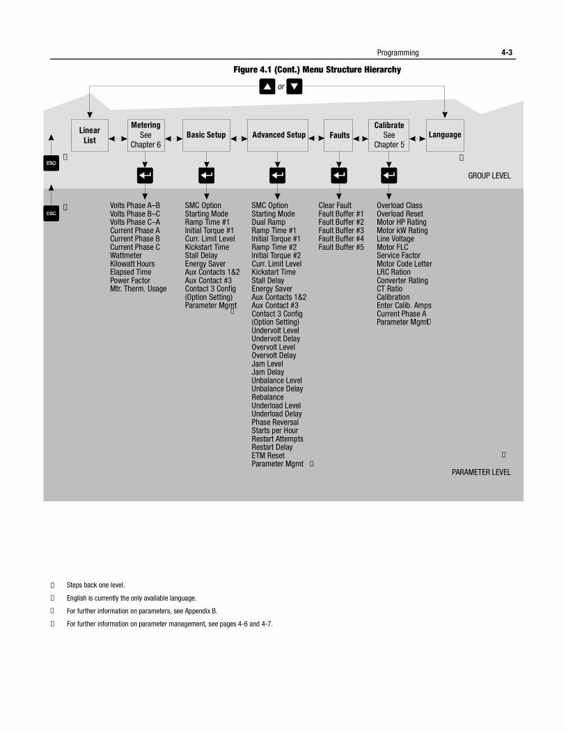
Programming 4-3
Figure 4.1 (Cont.) Menu Structure Hierarchy
① Steps back one level.
② English is currently the only available language.
③ For further information on parameters, see Appendix B.
④ For further information on parameter management, see pages 4-6 and 4-7.
LinearList
Basic Setup Advanced Setup Faults LanguageMetering
SeeChapter 6
CalibrateSee
Chapter 5
or
GROUP LEVEL
➁➀
➀ Volts Phase A–BVolts Phase B–CVolts Phase C–ACurrent Phase ACurrent Phase BCurrent Phase CWattmeterKilowatt HoursElapsed TimePower FactorMtr. Therm. Usage
SMC OptionStarting ModeRamp Time #1Initial Torque #1Curr. Limit LevelKickstart TimeStall DelayEnergy SaverAux Contacts 1&2Aux Contact #3Contact 3 Config(Option Setting)Parameter Mgmt
Clear FaultFault Buffer #1Fault Buffer #2Fault Buffer #3Fault Buffer #4Fault Buffer #5
Overload ClassOverload ResetMotor HP RatingMotor kW RatingLine VoltageMotor FLCService FactorMotor Code LetterLRC RationConverter RatingCT RatioCalibrationEnter Calib. AmpsCurrent Phase AParameter Mgmt.
SMC OptionStarting ModeDual RampRamp Time #1Initial Torque #1Ramp Time #2Initial Torque #2Curr. Limit LevelKickstart TimeStall DelayEnergy SaverAux Contacts 1&2Aux Contact #3Contact 3 Config(Option Setting)Undervolt LevelUndervolt DelayOvervolt LevelOvervolt DelayJam LevelJam DelayUnbalance LevelUnbalance DelayRebalanceUnderload LevelUnderload DelayPhase ReversalStarts per HourRestart AttemptsRestart DelayETM ResetParameter Mgmt ④
PARAMETER LEVEL
③
④
④
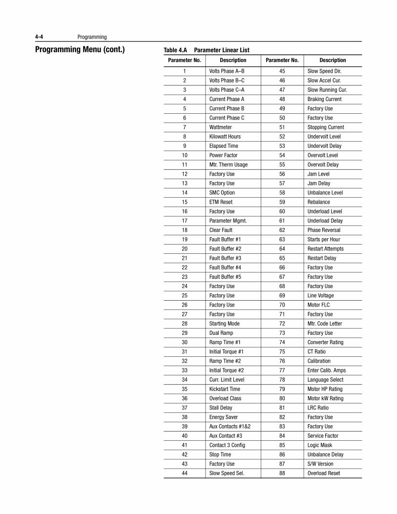
4-4 Programming
Programming Menu (cont.) Table 4.A Parameter Linear List
Parameter No. Description Parameter No. Description
1 Volts Phase A–B 45 Slow Speed Dir.
2 Volts Phase B–C 46 Slow Accel Cur.
3 Volts Phase C–A 47 Slow Running Cur.
4 Current Phase A 48 Braking Current
5 Current Phase B 49 Factory Use
6 Current Phase C 50 Factory Use
7 Wattmeter 51 Stopping Current
8 Kilowatt Hours 52 Undervolt Level
9 Elapsed Time 53 Undervolt Delay
10 Power Factor 54 Overvolt Level
11 Mtr. Therm Usage 55 Overvolt Delay
12 Factory Use 56 Jam Level
13 Factory Use 57 Jam Delay
14 SMC Option 58 Unbalance Level
15 ETM Reset 59 Rebalance
16 Factory Use 60 Underload Level
17 Parameter Mgmt. 61 Underload Delay
18 Clear Fault 62 Phase Reversal
19 Fault Buffer #1 63 Starts per Hour
20 Fault Buffer #2 64 Restart Attempts
21 Fault Buffer #3 65 Restart Delay
22 Fault Buffer #4 66 Factory Use
23 Fault Buffer #5 67 Factory Use
24 Factory Use 68 Factory Use
25 Factory Use 69 Line Voltage
26 Factory Use 70 Motor FLC
27 Factory Use 71 Factory Use
28 Starting Mode 72 Mtr. Code Letter
29 Dual Ramp 73 Factory Use
30 Ramp Time #1 74 Converter Rating
31 Initial Torque #1 75 CT Ratio
32 Ramp Time #2 76 Calibration
33 Initial Torque #2 77 Enter Calib. Amps
34 Curr. Limit Level 78 Language Select
35 Kickstart Time 79 Motor HP Rating
36 Overload Class 80 Motor kW Rating
37 Stall Delay 81 LRC Ratio
38 Energy Saver 82 Factory Use
39 Aux Contacts #1&2 83 Factory Use
40 Aux Contact #3 84 Service Factor
41 Contact 3 Config 85 Logic Mask
42 Stop Time 86 Unbalance Delay
43 Factory Use 87 S/W Version
44 Slow Speed Sel. 88 Overload Reset
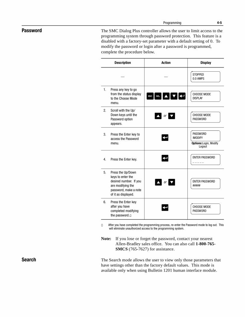
Programming 4-5
Password The SMC Dialog Plus controller allows the user to limit access to the programming system through password protection. This feature is a disabled with a factory-set parameter with a default setting of 0. To modify the password or login after a password is programmed, complete the procedure below.
① After you have completed the programming process, re-enter the Password mode to log out. This will eliminate unauthorized access to the programming system.
Note: If you lose or forget the password, contact your nearest Allen-Bradley sales office. You can also call 1-800-765-SMCS (765-7627) for assistance.
Search The Search mode allows the user to view only those parameters that have settings other than the factory default values. This mode is available only when using Bulletin 1201 human interface module.
Description Action Display
— —
1. Press any key to go from the status display to the Choose Mode menu.
2. Scroll with the Up/Down keys until the Password option appears.
3. Press the Enter key to access the Password menu.
4. Press the Enter key.
5. Press the Up/Down keys to enter the desired number. If you are modifying the password, make a note of it as displayed.
6. Press the Enter key after you have completed modifying the password.①
STOPPED0.0 AMPS
CHOOSE MODEDISPLAY
or CHOOSE MODEPASSWORD
PASSWORD|MODIFY
Options:Login, ModifyLogout
ENTER PASSWORD_ _ _ _ _
or ENTER PASSWORD#####
CHOOSE MODEPASSWORD
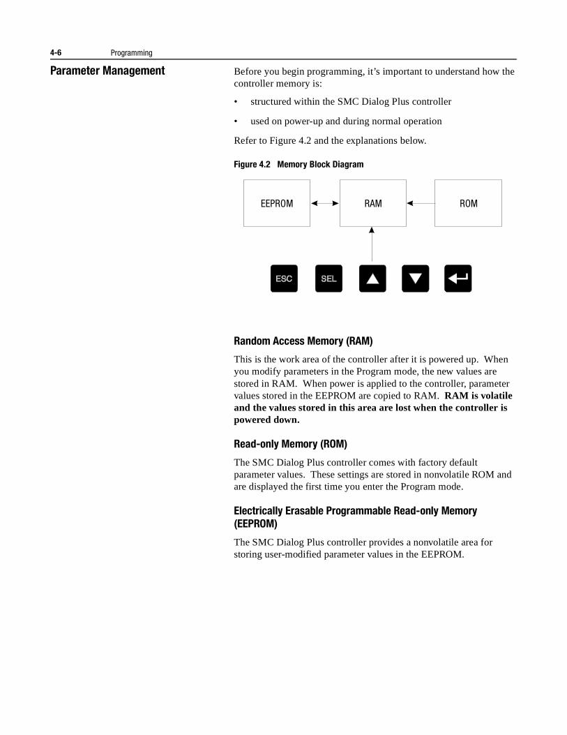
4-6 Programming
Parameter Management Before you begin programming, it’s important to understand how the controller memory is:
• structured within the SMC Dialog Plus controller
• used on power-up and during normal operation
Refer to Figure 4.2 and the explanations below.
Figure 4.2 Memory Block Diagram
Random Access Memory (RAM)
This is the work area of the controller after it is powered up. When you modify parameters in the Program mode, the new values are stored in RAM. When power is applied to the controller, parameter values stored in the EEPROM are copied to RAM. RAM is volatile and the values stored in this area are lost when the controller is powered down.
Read-only Memory (ROM)
The SMC Dialog Plus controller comes with factory default parameter values. These settings are stored in nonvolatile ROM and are displayed the first time you enter the Program mode.
Electrically Erasable Programmable Read-only Memory (EEPROM)
The SMC Dialog Plus controller provides a nonvolatile area for storing user-modified parameter values in the EEPROM.
EEPROM RAM ROM
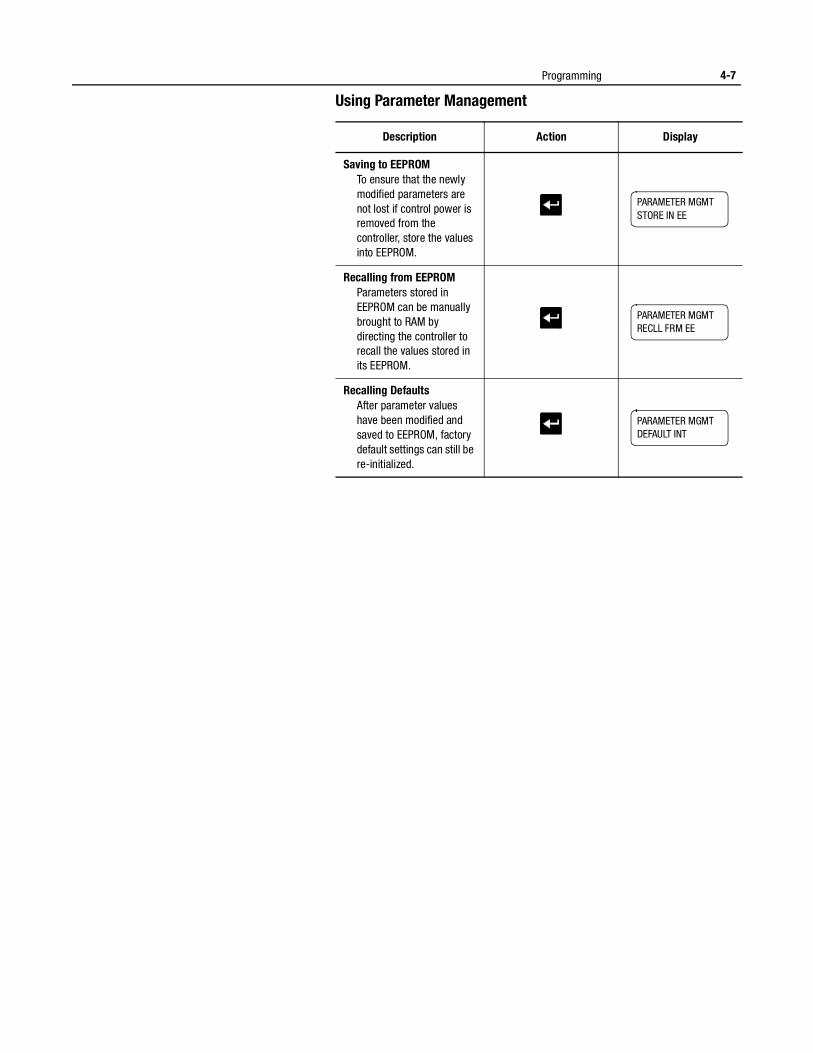
Programming 4-7
Using Parameter Management
Description Action Display
Saving to EEPROMTo ensure that the newly modified parameters are not lost if control power is removed from the controller, store the values into EEPROM.
Recalling from EEPROMParameters stored in EEPROM can be manually brought to RAM by directing the controller to recall the values stored in its EEPROM.
Recalling DefaultsAfter parameter values have been modified and saved to EEPROM, factory default settings can still be re-initialized.
PARAMETER MGMTSTORE IN EE
PARAMETER MGMTRECLL FRM EE
PARAMETER MGMTDEFAULT INT
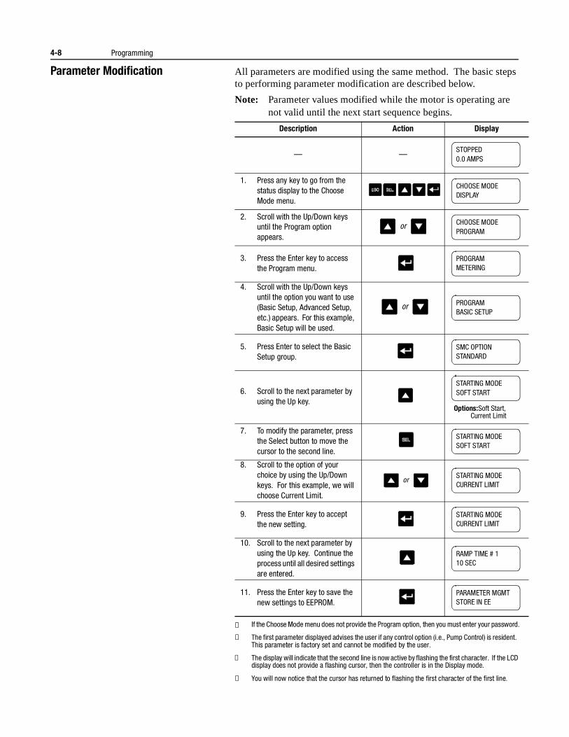
4-8 Programming
Parameter Modification All parameters are modified using the same method. The basic steps to performing parameter modification are described below.
Note: Parameter values modified while the motor is operating are not valid until the next start sequence begins.
① If the Choose Mode menu does not provide the Program option, then you must enter your password.
② The first parameter displayed advises the user if any control option (i.e., Pump Control) is resident. This parameter is factory set and cannot be modified by the user.
③ The display will indicate that the second line is now active by flashing the first character. If the LCD display does not provide a flashing cursor, then the controller is in the Display mode.
④ You will now notice that the cursor has returned to flashing the first character of the first line.
Description Action Display
— —
1. Press any key to go from the status display to the Choose Mode menu.
2. Scroll with the Up/Down keys until the Program option appears.
3. Press the Enter key to access the Program menu.
4. Scroll with the Up/Down keys until the option you want to use (Basic Setup, Advanced Setup, etc.) appears. For this example, Basic Setup will be used.
5. Press Enter to select the Basic Setup group.
6. Scroll to the next parameter by using the Up key.
7. To modify the parameter, press the Select button to move the cursor to the second line.
8. Scroll to the option of your choice by using the Up/Down keys. For this example, we will choose Current Limit.
9. Press the Enter key to accept the new setting.
10. Scroll to the next parameter by using the Up key. Continue the process until all desired settings are entered.
11. Press the Enter key to save the new settings to EEPROM.
STOPPED0.0 AMPS
CHOOSE MODEDISPLAY
or CHOOSE MODEPROGRAM
PROGRAMMETERING
or PROGRAMBASIC SETUP
SMC OPTIONSTANDARD
STARTING MODESOFT START
Options:Soft Start,Current Limit
STARTING MODESOFT START
orSTARTING MODECURRENT LIMIT
STARTING MODECURRENT LIMIT
RAMP TIME # 110 SEC
PARAMETER MGMTSTORE IN EE
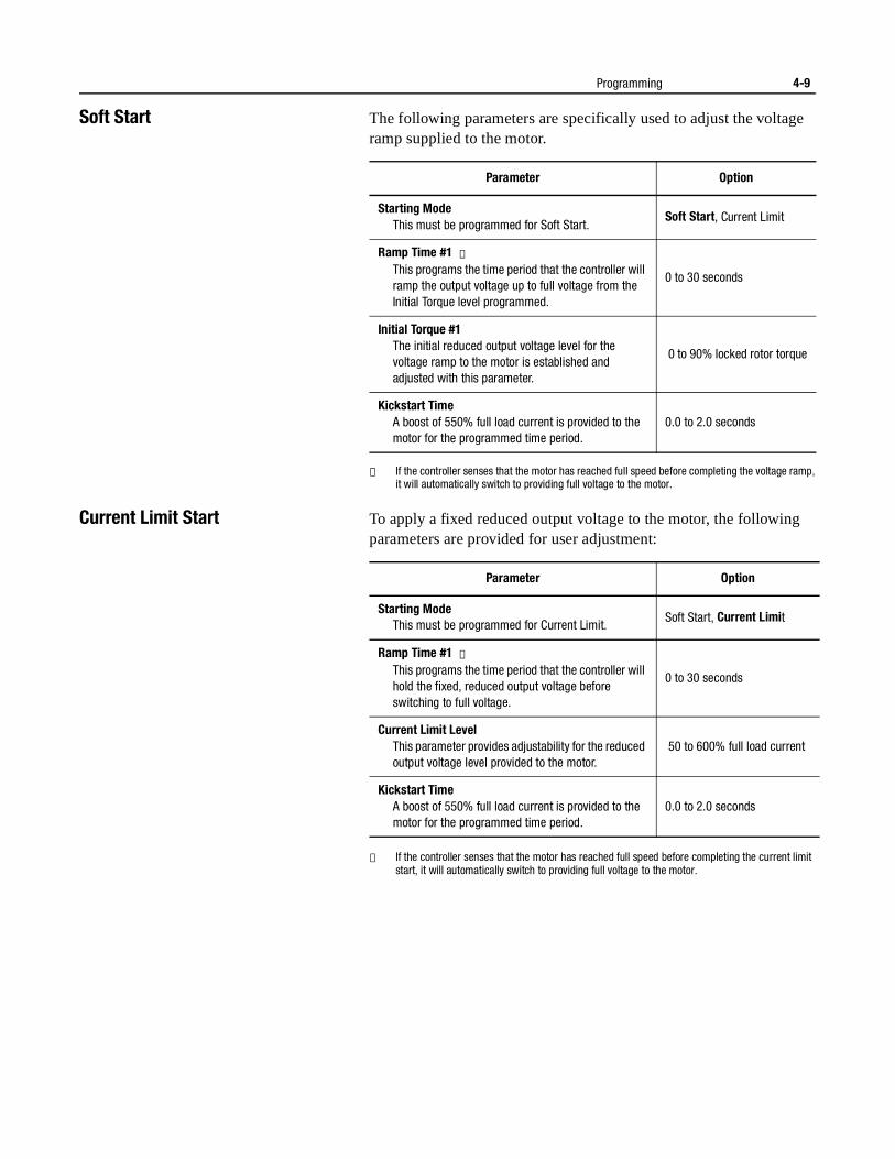
Programming 4-9
Soft Start The following parameters are specifically used to adjust the voltage ramp supplied to the motor.
① If the controller senses that the motor has reached full speed before completing the voltage ramp, it will automatically switch to providing full voltage to the motor.
Current Limit Start To apply a fixed reduced output voltage to the motor, the following parameters are provided for user adjustment:
① If the controller senses that the motor has reached full speed before completing the current limit start, it will automatically switch to providing full voltage to the motor.
Parameter Option
Starting Mode This must be programmed for Soft Start.
Soft Start, Current Limit
Ramp Time #1 ①This programs the time period that the controller will ramp the output voltage up to full voltage from the Initial Torque level programmed.
0 to 30 seconds
Initial Torque #1 The initial reduced output voltage level for the voltage ramp to the motor is established and adjusted with this parameter.
0 to 90% locked rotor torque
Kickstart Time A boost of 550% full load current is provided to the motor for the programmed time period.
0.0 to 2.0 seconds
Parameter Option
Starting Mode This must be programmed for Current Limit.
Soft Start, Current Limit
Ramp Time #1 ①This programs the time period that the controller will hold the fixed, reduced output voltage before switching to full voltage.
0 to 30 seconds
Current Limit LevelThis parameter provides adjustability for the reduced output voltage level provided to the motor.
50 to 600% full load current
Kickstart Time A boost of 550% full load current is provided to the motor for the programmed time period.
0.0 to 2.0 seconds
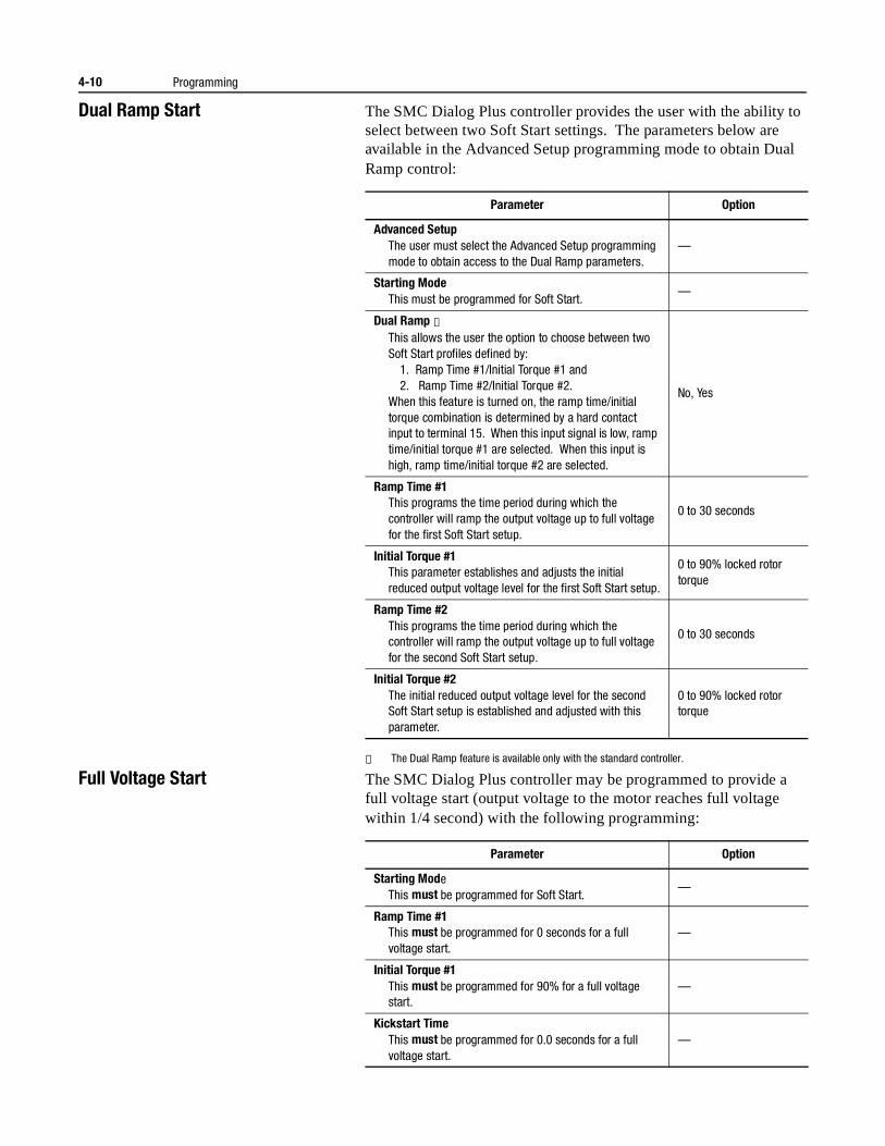
4-10 Programming
Dual Ramp Start The SMC Dialog Plus controller provides the user with the ability to select between two Soft Start settings. The parameters below are available in the Advanced Setup programming mode to obtain Dual Ramp control:
① The Dual Ramp feature is available only with the standard controller.
Full Voltage Start The SMC Dialog Plus controller may be programmed to provide a full voltage start (output voltage to the motor reaches full voltage within 1/4 second) with the following programming:
Parameter Option
Advanced SetupThe user must select the Advanced Setup programming mode to obtain access to the Dual Ramp parameters.
—
Starting ModeThis must be programmed for Soft Start.
—
Dual Ramp ①This allows the user the option to choose between two Soft Start profiles defined by:
1. Ramp Time #1/Initial Torque #1 and 2. Ramp Time #2/Initial Torque #2.
When this feature is turned on, the ramp time/initial torque combination is determined by a hard contact input to terminal 15. When this input signal is low, ramp time/initial torque #1 are selected. When this input is high, ramp time/initial torque #2 are selected.
No, Yes
Ramp Time #1This programs the time period during which the controller will ramp the output voltage up to full voltage for the first Soft Start setup.
0 to 30 seconds
Initial Torque #1This parameter establishes and adjusts the initial reduced output voltage level for the first Soft Start setup.
0 to 90% locked rotor torque
Ramp Time #2This programs the time period during which the controller will ramp the output voltage up to full voltage for the second Soft Start setup.
0 to 30 seconds
Initial Torque #2The initial reduced output voltage level for the second Soft Start setup is established and adjusted with this parameter.
0 to 90% locked rotor torque
Parameter Option
Starting ModeThis must be programmed for Soft Start.
—
Ramp Time #1This must be programmed for 0 seconds for a full voltage start.
—
Initial Torque #1This must be programmed for 90% for a full voltage start.
—
Kickstart TimeThis must be programmed for 0.0 seconds for a full voltage start.
—
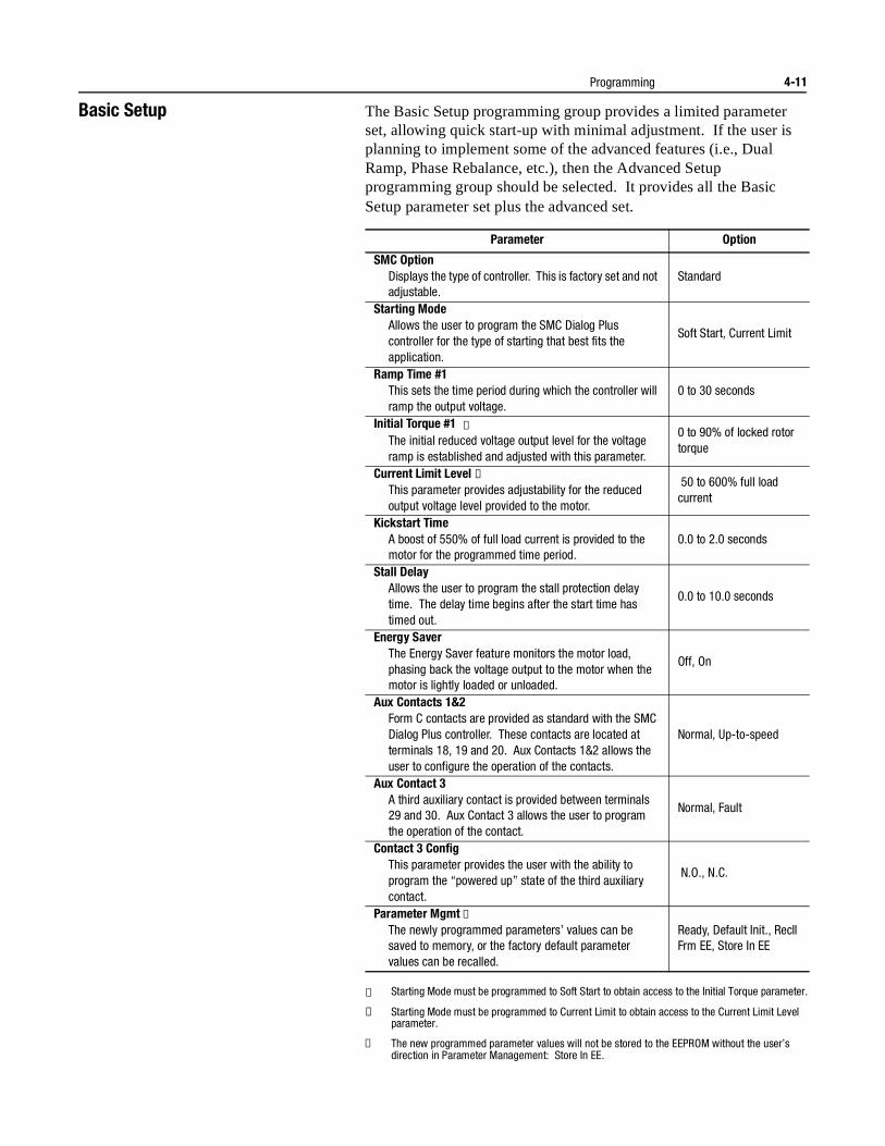
Programming 4-11
Basic Setup The Basic Setup programming group provides a limited parameter set, allowing quick start-up with minimal adjustment. If the user is planning to implement some of the advanced features (i.e., Dual Ramp, Phase Rebalance, etc.), then the Advanced Setup programming group should be selected. It provides all the Basic Setup parameter set plus the advanced set.
① Starting Mode must be programmed to Soft Start to obtain access to the Initial Torque parameter.
② Starting Mode must be programmed to Current Limit to obtain access to the Current Limit Level parameter.
③ The new programmed parameter values will not be stored to the EEPROM without the user’s direction in Parameter Management: Store In EE.
Parameter Option
SMC Option Displays the type of controller. This is factory set and not adjustable.
Standard
Starting Mode Allows the user to program the SMC Dialog Plus controller for the type of starting that best fits the application.
Soft Start, Current Limit
Ramp Time #1This sets the time period during which the controller will ramp the output voltage.
0 to 30 seconds
Initial Torque #1 ①The initial reduced voltage output level for the voltage ramp is established and adjusted with this parameter.
0 to 90% of locked rotor torque
Current Limit Level ②This parameter provides adjustability for the reduced output voltage level provided to the motor.
50 to 600% full load current
Kickstart Time A boost of 550% of full load current is provided to the motor for the programmed time period.
0.0 to 2.0 seconds
Stall Delay Allows the user to program the stall protection delay time. The delay time begins after the start time has timed out.
0.0 to 10.0 seconds
Energy Saver The Energy Saver feature monitors the motor load, phasing back the voltage output to the motor when the motor is lightly loaded or unloaded.
Off, On
Aux Contacts 1&2 Form C contacts are provided as standard with the SMC Dialog Plus controller. These contacts are located at terminals 18, 19 and 20. Aux Contacts 1&2 allows the user to configure the operation of the contacts.
Normal, Up-to-speed
Aux Contact 3 A third auxiliary contact is provided between terminals 29 and 30. Aux Contact 3 allows the user to program the operation of the contact.
Normal, Fault
Contact 3 Config This parameter provides the user with the ability to program the “powered up” state of the third auxiliary contact.
N.O., N.C.
Parameter Mgmt ③The newly programmed parameters’ values can be saved to memory, or the factory default parameter values can be recalled.
Ready, Default Init., Recll Frm EE, Store In EE
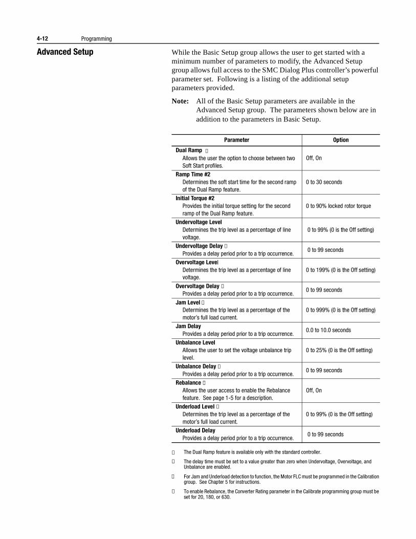
4-12 Programming
Advanced Setup While the Basic Setup group allows the user to get started with a minimum number of parameters to modify, the Advanced Setup group allows full access to the SMC Dialog Plus controller’s powerful parameter set. Following is a listing of the additional setup parameters provided.
Note: All of the Basic Setup parameters are available in the Advanced Setup group. The parameters shown below are in addition to the parameters in Basic Setup.
① The Dual Ramp feature is available only with the standard controller.
② The delay time must be set to a value greater than zero when Undervoltage, Overvoltage, and Unbalance are enabled.
③ For Jam and Underload detection to function, the Motor FLC must be programmed in the Calibration group. See Chapter 5 for instructions.
④ To enable Rebalance, the Converter Rating parameter in the Calibrate programming group must be set for 20, 180, or 630.
Parameter Option
Dual Ramp ①Allows the user the option to choose between two Soft Start profiles.
Off, On
Ramp Time #2Determines the soft start time for the second ramp of the Dual Ramp feature.
0 to 30 seconds
Initial Torque #2Provides the initial torque setting for the second ramp of the Dual Ramp feature.
0 to 90% locked rotor torque
Undervoltage LevelDetermines the trip level as a percentage of line voltage.
0 to 99% (0 is the Off setting)
Undervoltage Delay ②Provides a delay period prior to a trip occurrence.
0 to 99 seconds
Overvoltage LevelDetermines the trip level as a percentage of line voltage.
0 to 199% (0 is the Off setting)
Overvoltage Delay ②Provides a delay period prior to a trip occurrence.
0 to 99 seconds
Jam Level ③Determines the trip level as a percentage of the motor’s full load current.
0 to 999% (0 is the Off setting)
Jam DelayProvides a delay period prior to a trip occurrence.
0.0 to 10.0 seconds
Unbalance LevelAllows the user to set the voltage unbalance trip level.
0 to 25% (0 is the Off setting)
Unbalance Delay ②Provides a delay period prior to a trip occurrence.
0 to 99 seconds
Rebalance ④Allows the user access to enable the Rebalance feature. See page 1-5 for a description.
Off, On
Underload Level ②Determines the trip level as a percentage of the motor’s full load current.
0 to 99% (0 is the Off setting)
Underload DelayProvides a delay period prior to a trip occurrence.
0 to 99 seconds
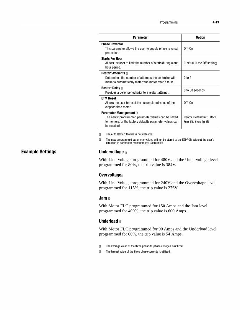
Programming 4-13
① The Auto Restart feature is not available.
② The new programmed parameter values will not be stored to the EEPROM without the user’s direction in parameter management: Store In EE
Example Settings Undervoltage ①
With Line Voltage programmed for 480V and the Undervoltage level programmed for 80%, the trip value is 384V.
Overvoltage①
With Line Voltage programmed for 240V and the Overvoltage level programmed for 115%, the trip value is 276V.
Jam ②
With Motor FLC programmed for 150 Amps and the Jam level programmed for 400%, the trip value is 600 Amps.
Underload ②
With Motor FLC programmed for 90 Amps and the Underload level programmed for 60%, the trip value is 54 Amps.
① The average value of the three phase-to-phase voltages is utilized.
② The largest value of the three phase currents is utilized.
Parameter Option
Phase ReversalThis parameter allows the user to enable phase reversal protection.
Off, On
Starts Per HourAllows the user to limit the number of starts during a one hour period.
0–99 (0 is the Off setting)
Restart Attempts ①Determines the number of attempts the controller will make to automatically restart the motor after a fault.
0 to 5
Restart Delay ①Provides a delay period prior to a restart attempt.
0 to 60 seconds
ETM ResetAllows the user to reset the accumulated value of the elapsed time meter.
Off, On
Parameter Management ②The newly programmed parameter values can be saved to memory, or the factory defaults parameter values can be recalled.
Ready, Default Init., Recll Frm EE, Store In EE

4-14 Programming
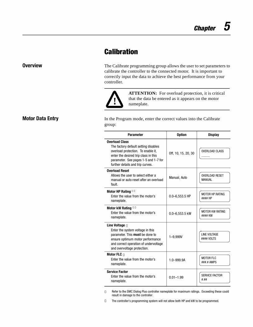
Chapter 5
Calibration
Overview The Calibrate programming group allows the user to set parameters to calibrate the controller to the connected motor. It is important to correctly input the data to achieve the best performance from your controller.
Motor Data Entry In the Program mode, enter the correct values into the Calibrate group:
① Refer to the SMC Dialog Plus controller nameplate for maximum ratings. Exceeding these could result in damage to the controller.
② The controller’s programming system will not allow both HP and kW to be programmed.
!ATTENTION: For overload protection, it is critical that the data be entered as it appears on the motor nameplate.
Parameter Option Display
Overload ClassThe factory default setting disables overload protection. To enable it, enter the desired trip class in this parameter. See pages 1-5 and 1-7 for further details and trip curves.
Off, 10, 15, 20, 30
Overload ResetAllows the user to select either a manual or auto reset after an overload fault.
Manual, Auto
Motor HP Rating ①②
Enter the value from the motor’s nameplate.
0.0–6,553.5 HP
Motor kW Rating ①②
Enter the value from the motor’s nameplate.
0.0–6,553.5 kW
Line Voltage ①Enter the system voltage in this parameter. This must be done to ensure optimum motor performance and correct operation of undervoltage and overvoltage protection.
1–9,999V
Motor FLC ①Enter the value from the motor’s nameplate.
1.0–999.9A
Service FactorEnter the value from the motor’s nameplate.
0.01–1.99
OVERLOAD CLASS_____
OVERLOAD RESETMANUAL
MOTOR HP RATING#### HP
MOTOR KW RATING#### KW
LINE VOLTAGE#### VOLTS
MOTOR FLC###.# AMPS
SERVICE FACTOR#.##
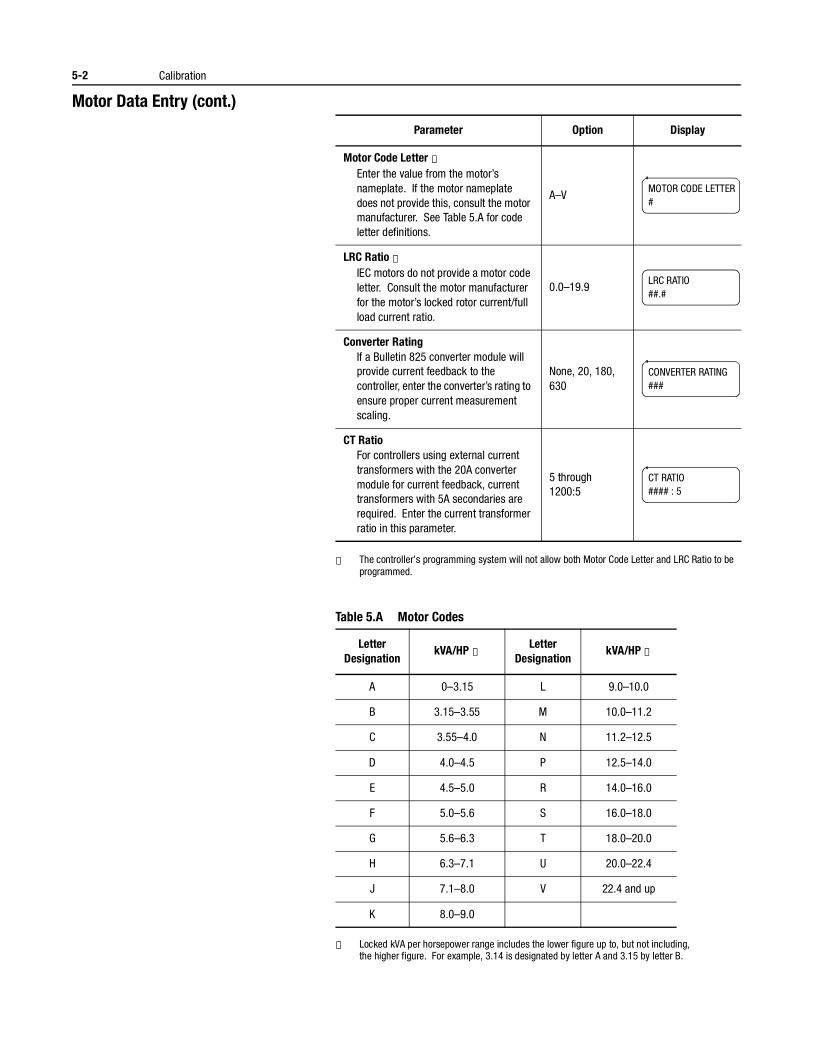
5-2 Calibration
Motor Data Entry (cont.)
① The controller’s programming system will not allow both Motor Code Letter and LRC Ratio to be programmed.
Table 5.A Motor Codes
① Locked kVA per horsepower range includes the lower figure up to, but not including, the higher figure. For example, 3.14 is designated by letter A and 3.15 by letter B.
Parameter Option Display
Motor Code Letter ①Enter the value from the motor’s nameplate. If the motor nameplate does not provide this, consult the motor manufacturer. See Table 5.A for code letter definitions.
A–V
LRC Ratio ①IEC motors do not provide a motor code letter. Consult the motor manufacturer for the motor’s locked rotor current/full load current ratio.
0.0–19.9
Converter RatingIf a Bulletin 825 converter module will provide current feedback to the controller, enter the converter’s rating to ensure proper current measurement scaling.
None, 20, 180, 630
CT RatioFor controllers using external current transformers with the 20A converter module for current feedback, current transformers with 5A secondaries are required. Enter the current transformer ratio in this parameter.
5 through 1200:5
MOTOR CODE LETTER#
LRC RATIO##.#
CONVERTER RATING###
CT RATIO#### : 5
LetterDesignation
kVA/HP ①Letter
DesignationkVA/HP ①
A 0–3.15 L 9.0–10.0
B 3.15–3.55 M 10.0–11.2
C 3.55–4.0 N 11.2–12.5
D 4.0–4.5 P 12.5–14.0
E 4.5–5.0 R 14.0–16.0
F 5.0–5.6 S 16.0–18.0
G 5.6–6.3 T 18.0–20.0
H 6.3–7.1 U 20.0–22.4
J 7.1–8.0 V 22.4 and up
K 8.0–9.0
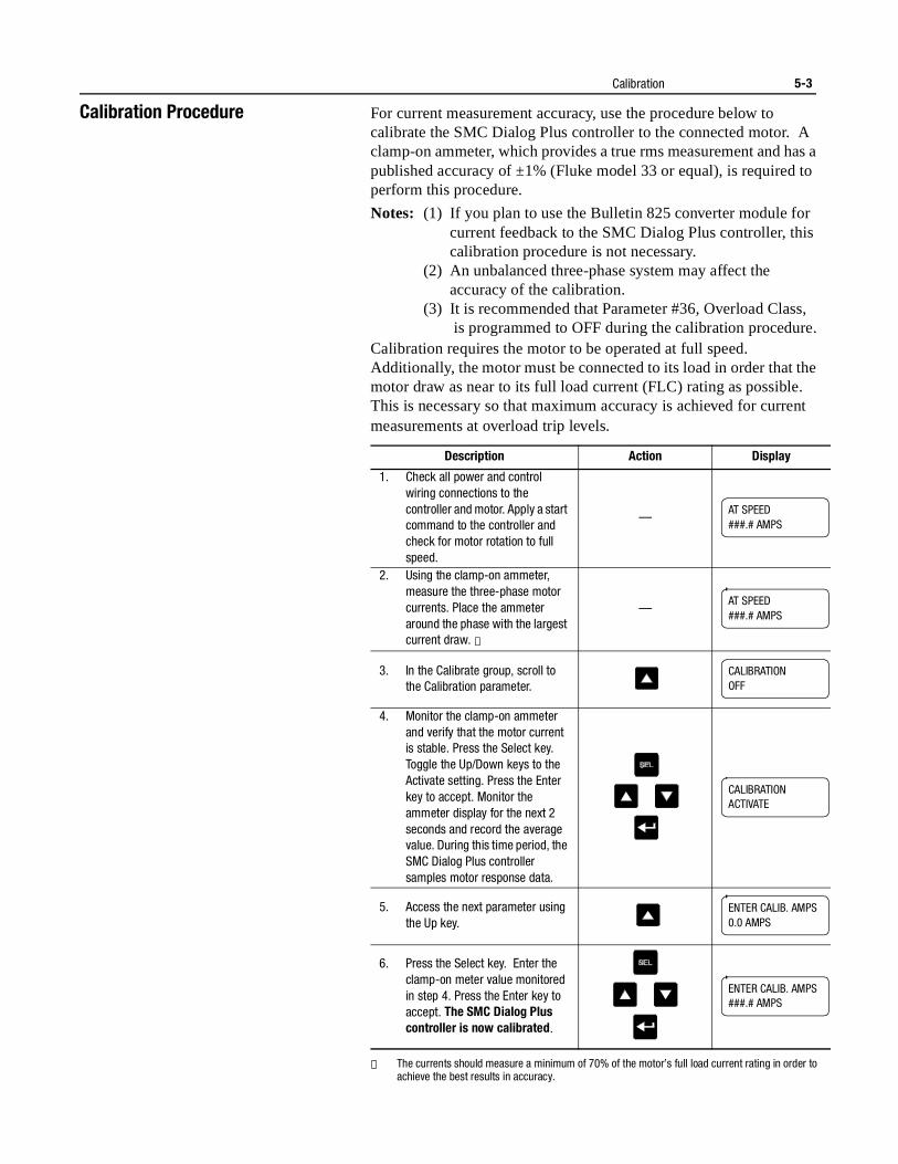
Calibration 5-3
Calibration Procedure For current measurement accuracy, use the procedure below to calibrate the SMC Dialog Plus controller to the connected motor. A clamp-on ammeter, which provides a true rms measurement and has a published accuracy of ±1% (Fluke model 33 or equal), is required to perform this procedure.
Notes: (1) If you plan to use the Bulletin 825 converter module for current feedback to the SMC Dialog Plus controller, this calibration procedure is not necessary.
(2) An unbalanced three-phase system may affect theaccuracy of the calibration.
(3) It is recommended that Parameter #36, Overload Class, is programmed to OFF during the calibration procedure.
Calibration requires the motor to be operated at full speed. Additionally, the motor must be connected to its load in order that the motor draw as near to its full load current (FLC) rating as possible. This is necessary so that maximum accuracy is achieved for current measurements at overload trip levels.
① The currents should measure a minimum of 70% of the motor’s full load current rating in order to achieve the best results in accuracy.
Description Action Display
1. Check all power and control wiring connections to the controller and motor. Apply a start command to the controller and check for motor rotation to full speed.
—
2. Using the clamp-on ammeter, measure the three-phase motor currents. Place the ammeter around the phase with the largest current draw. ①
—
3. In the Calibrate group, scroll to the Calibration parameter.
4. Monitor the clamp-on ammeter and verify that the motor current is stable. Press the Select key. Toggle the Up/Down keys to the Activate setting. Press the Enter key to accept. Monitor the ammeter display for the next 2 seconds and record the average value. During this time period, the SMC Dialog Plus controller samples motor response data.
5. Access the next parameter using the Up key.
6. Press the Select key. Enter the clamp-on meter value monitored in step 4. Press the Enter key to accept. The SMC Dialog Plus controller is now calibrated.
AT SPEED###.# AMPS
AT SPEED###.# AMPS
CALIBRATION OFF
CALIBRATIONACTIVATE
ENTER CALIB. AMPS0.0 AMPS
ENTER CALIB. AMPS###.# AMPS
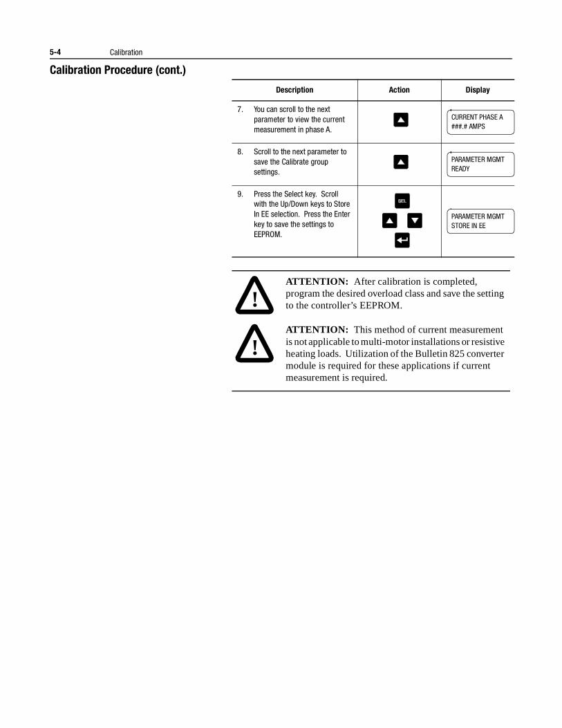
5-4 Calibration
Calibration Procedure (cont.)
Description Action Display
7. You can scroll to the next parameter to view the current measurement in phase A.
8. Scroll to the next parameter to save the Calibrate group settings.
9. Press the Select key. Scroll with the Up/Down keys to Store In EE selection. Press the Enter key to save the settings to EEPROM.
!ATTENTION: After calibration is completed, program the desired overload class and save the setting to the controller’s EEPROM.
!ATTENTION: This method of current measurement is not applicable to multi-motor installations or resistive heating loads. Utilization of the Bulletin 825 converter module is required for these applications if current measurement is required.
CURRENT PHASE A###.# AMPS
PARAMETER MGMTREADY
PARAMETER MGMTSTORE IN EE
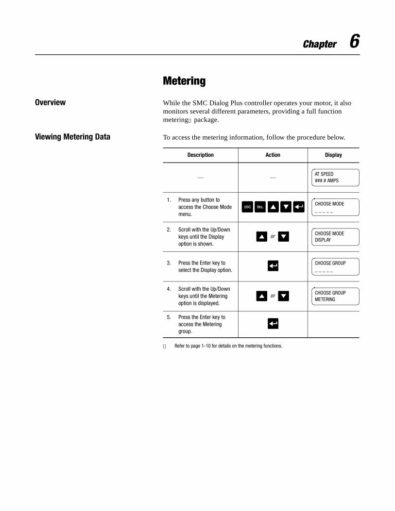
Chapter 6
Metering
Overview While the SMC Dialog Plus controller operates your motor, it also monitors several different parameters, providing a full function metering① package.
Viewing Metering Data To access the metering information, follow the procedure below.
① Refer to page 1-10 for details on the metering functions.
Description Action Display
— —
1. Press any button to access the Choose Mode menu.
2. Scroll with the Up/Down keys until the Display option is shown.
3. Press the Enter key to select the Display option.
4. Scroll with the Up/Down keys until the Metering option is displayed.
5. Press the Enter key to access the Metering group.
AT SPEED###.# AMPS
CHOOSE MODE_ _ _ _ _
or CHOOSE MODEDISPLAY
CHOOSE GROUP_ _ _ _ _
or CHOOSE GROUPMETERING
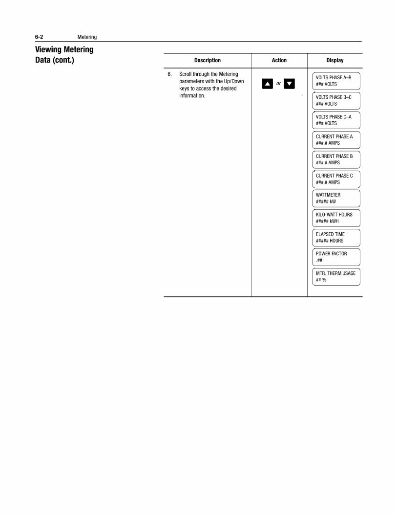
6-2 Metering
Viewing Metering Data (cont.)
Description Action Display
6. Scroll through the Metering parameters with the Up/Down keys to access the desired information. .
orVOLTS PHASE A–B### VOLTS
VOLTS PHASE B–C### VOLTS
VOLTS PHASE C–A### VOLTS
CURRENT PHASE A###.# AMPS
CURRENT PHASE B###.# AMPS
CURRENT PHASE C###.# AMPS
WATTMETER##### kW
KILO-WATT HOURS##### kWH
ELAPSED TIME##### HOURS
POWER FACTOR.##
MTR. THERM USAGE## %
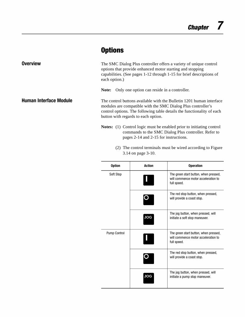
Chapter 7
Options
Overview The SMC Dialog Plus controller offers a variety of unique control options that provide enhanced motor starting and stopping capabilities. (See pages 1-12 through 1-15 for brief descriptions of each option.)
Note: Only one option can reside in a controller.
Human Interface Module The control buttons available with the Bulletin 1201 human interface modules are compatible with the SMC Dialog Plus controller’s control options. The following table details the functionality of each button with regards to each option.
Notes: (1) Control logic must be enabled prior to initiating control commands to the SMC Dialog Plus controller. Refer to pages 2-14 and 2-15 for instructions.
(2) The control terminals must be wired according to Figure 3.14 on page 3-10.
Option Action Operation
Soft Stop The green start button, when pressed, will commence motor acceleration to full speed.
The red stop button, when pressed, will provide a coast stop.
The jog button, when pressed, will initiate a soft stop maneuver.
Pump Control The green start button, when pressed, will commence motor acceleration to full speed.
The red stop button, when pressed, will provide a coast stop.
The jog button, when pressed, will initiate a pump stop maneuver.
JOG
JOG
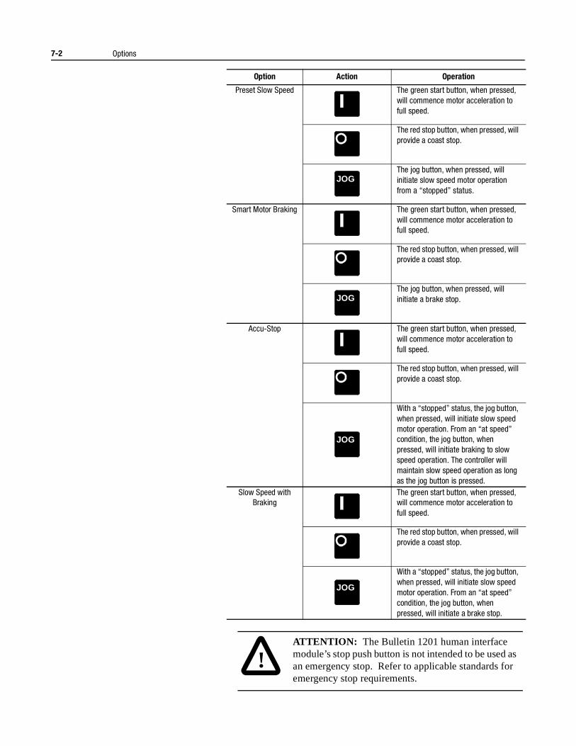
7-2 Options
Option Action Operation
Preset Slow Speed The green start button, when pressed, will commence motor acceleration to full speed.
The red stop button, when pressed, will provide a coast stop.
The jog button, when pressed, will initiate slow speed motor operation from a “stopped” status.
Smart Motor Braking The green start button, when pressed, will commence motor acceleration to full speed.
The red stop button, when pressed, will provide a coast stop.
The jog button, when pressed, will initiate a brake stop.
Accu-Stop The green start button, when pressed, will commence motor acceleration to full speed.
The red stop button, when pressed, will provide a coast stop.
With a “stopped” status, the jog button, when pressed, will initiate slow speed motor operation. From an “at speed” condition, the jog button, when pressed, will initiate braking to slow speed operation. The controller will maintain slow speed operation as long as the jog button is pressed.
Slow Speed with Braking
The green start button, when pressed, will commence motor acceleration to full speed.
The red stop button, when pressed, will provide a coast stop.
With a “stopped” status, the jog button, when pressed, will initiate slow speed motor operation. From an “at speed” condition, the jog button, when pressed, will initiate a brake stop.
JOG
JOG
JOG
JOG
!ATTENTION: The Bulletin 1201 human interface module’s stop push button is not intended to be used as an emergency stop. Refer to applicable standards for emergency stop requirements.
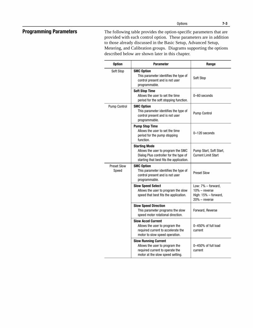
Options 7-3
Programming Parameters The following table provides the option-specific parameters that are provided with each control option. These parameters are in addition to those already discussed in the Basic Setup, Advanced Setup, Metering, and Calibration groups. Diagrams supporting the options described below are shown later in this chapter.
Option Parameter Range
Soft Stop SMC OptionThis parameter identifies the type of control present and is not user programmable.
Soft Stop
Soft Stop TimeAllows the user to set the time period for the soft stopping function.
0–60 seconds
Pump Control SMC OptionThis parameter identifies the type of control present and is not user programmable.
Pump Control
Pump Stop TimeAllows the user to set the time period for the pump stopping function.
0–120 seconds
Starting ModeAllows the user to program the SMC Dialog Plus controller for the type of starting that best fits the application.
Pump Start, Soft Start, Current Limit Start
Preset Slow Speed
SMC OptionThis parameter identifies the type of control present and is not user programmable.
Preset Slow
Slow Speed SelectAllows the user to program the slow speed that best fits the application.
Low: 7% – forward, 10% – reverseHigh: 15% – forward, 20% – reverse
Slow Speed DirectionThis parameter programs the slow speed motor rotational direction.
Forward, Reverse
Slow Accel CurrentAllows the user to program the required current to accelerate the motor to slow speed operation.
0–450% of full load current
Slow Running CurrentAllows the user to program the required current to operate the motor at the slow speed setting.
0–450% of full load current
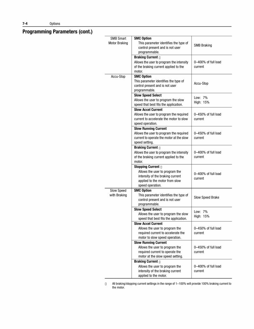
7-4 Options
Programming Parameters (cont.)
① All braking/stopping current settings in the range of 1–100% will provide 100% braking current to the motor.
SMB Smart Motor Braking
SMC OptionThis parameter identifies the type of control present and is not user programmable.
SMB Braking
Braking Current ①Allows the user to program the intensity of the braking current applied to the motor.
0–400% of full load current
Accu-Stop SMC OptionThis parameter identifies the type of control present and is not user programmable.
Accu-Stop
Slow Speed SelectAllows the user to program the slow speed that best fits the application.
Low: 7%High: 15%
Slow Accel CurrentAllows the user to program the required current to accelerate the motor to slow speed operation.
0–450% of full load current
Slow Running CurrentAllows the user to program the required current to operate the motor at the slow speed setting.
0–450% of full load current
Braking Current ①Allows the user to program the intensity of the braking current applied to the motor.
0–400% of full load current
Stopping Current ①Allows the user to program the intensity of the braking current applied to the motor from slow speed operation.
0–400% of full load current
Slow Speed with Braking
SMC OptionThis parameter identifies the type of control present and is not user programmable.
Slow Speed Brake
Slow Speed SelectAllows the user to program the slow speed that best fits the application.
Low: 7%High: 15%
Slow Accel CurrentAllows the user to program the required current to accelerate the motor to slow speed operation.
0–450% of full load current
Slow Running CurrentAllows the user to program the required current to operate the motor at the slow speed setting.
0–450% of full load current
Braking Current ①Allows the user to program the intensity of the braking current applied to the motor.
0–400% of full load current
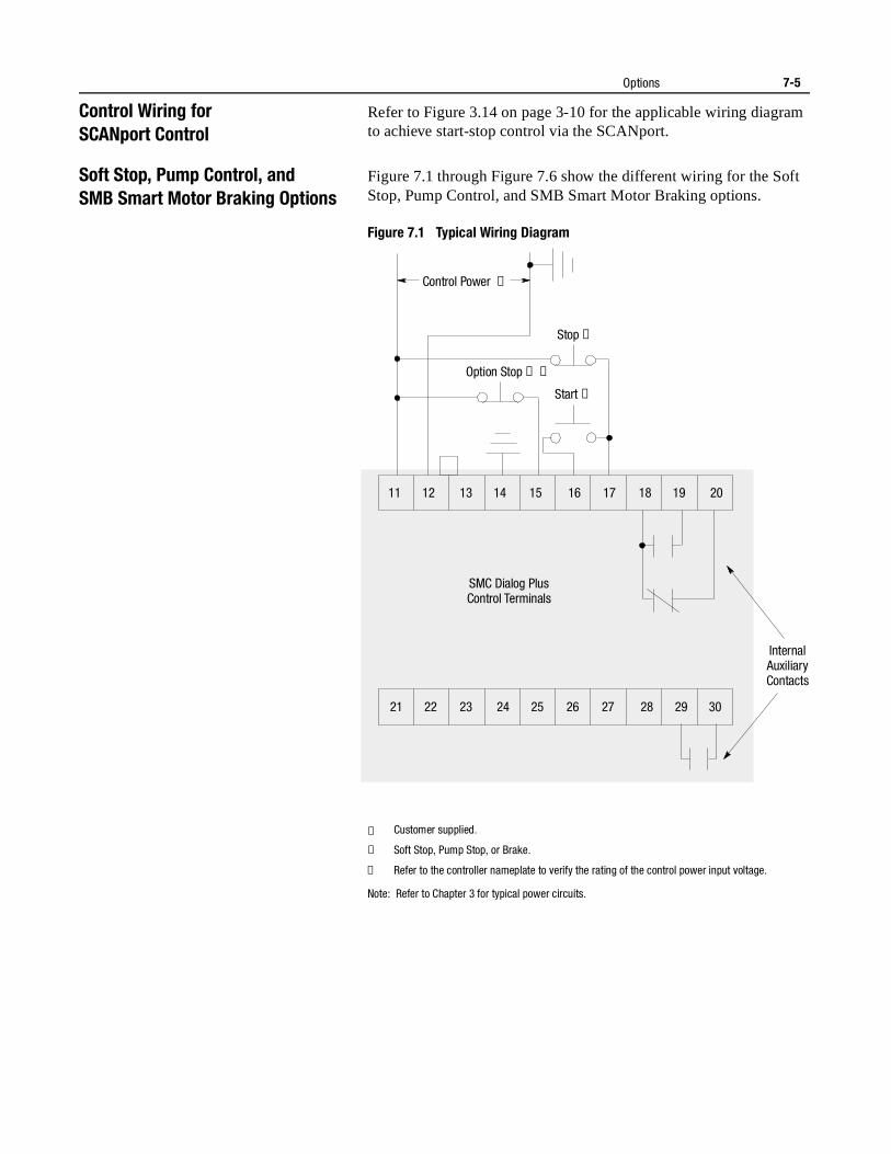
Options 7-5
Control Wiring forSCANport Control
Refer to Figure 3.14 on page 3-10 for the applicable wiring diagram to achieve start-stop control via the SCANport.
Soft Stop, Pump Control, andSMB Smart Motor Braking Options
Figure 7.1 through Figure 7.6 show the different wiring for the Soft Stop, Pump Control, and SMB Smart Motor Braking options.
Figure 7.1 Typical Wiring Diagram
① Customer supplied.
② Soft Stop, Pump Stop, or Brake.
③ Refer to the controller nameplate to verify the rating of the control power input voltage.
Note: Refer to Chapter 3 for typical power circuits.
Stop ➀
Control Power ➂
Option Stop ➀ ➁
Start ➀
11 12 13 14 15 16 17 18 19 20
21 22 23 24 25 26 27 28 29 30
Internal AuxiliaryContacts
SMC Dialog PlusControl Terminals
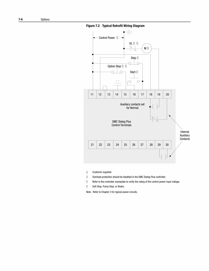
7-6 Options
Figure 7.2 Typical Retrofit Wiring Diagram
① Customer supplied.
② Overload protection should be disabled in the SMC Dialog Plus controller.
③ Refer to the controller nameplate to verify the rating of the control power input voltage.
④ Soft Stop, Pump Stop, or Brake.
Note: Refer to Chapter 3 for typical power circuits.
Stop ➀
OL ➀ ➁
M ➀
Control Power ➂
Option Stop ➀ ➃
Start ➀
11 12 13 14 15 16 17 18 19 20
21 22 23 24 25 26 27 28 29 30
Internal AuxiliaryContacts
Auxiliary contacts setfor Normal
SMC Dialog PlusControl Terminals
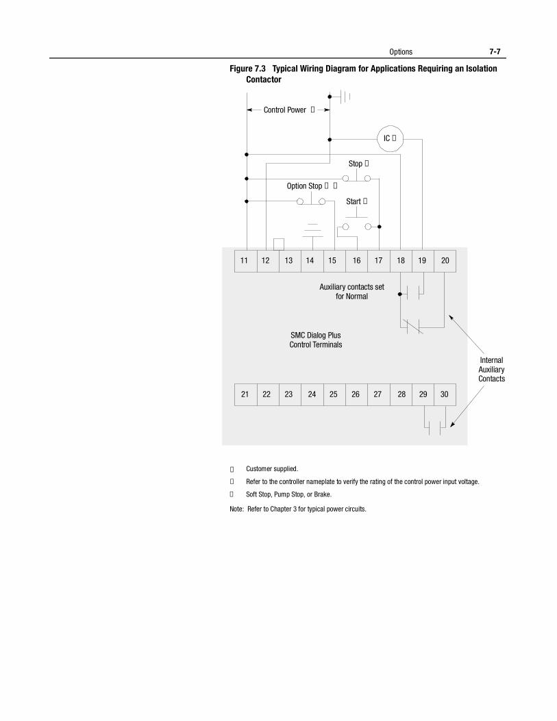
Options 7-7
Figure 7.3 Typical Wiring Diagram for Applications Requiring an Isolation Contactor
① Customer supplied.
② Refer to the controller nameplate to verify the rating of the control power input voltage.
③ Soft Stop, Pump Stop, or Brake.
Note: Refer to Chapter 3 for typical power circuits.
Stop ➀
IC ➀
Control Power ➁
Option Stop ➀ ➂
Start ➀
11 12 13 14 15 16 17 18 19 20
21 22 23 24 25 26 27 28 29 30
Internal AuxiliaryContacts
Auxiliary contacts setfor Normal
SMC Dialog PlusControl Terminals
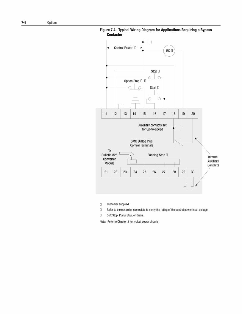
7-8 Options
Figure 7.4 Typical Wiring Diagram for Applications Requiring a Bypass Contactor
① Customer supplied.
② Refer to the controller nameplate to verify the rating of the control power input voltage.
③ Soft Stop, Pump Stop, or Brake.
Note: Refer to Chapter 3 for typical power circuits.
Stop ➀
BC ➀Control Power ➁
Option Stop ➀ ➂
Start ➀
11 12 13 14 15 16 17 18 19 20
21 22 23 24 25 26 27 28 29 30
Internal AuxiliaryContacts
ToBulletin 825ConverterModule
Auxiliary contacts setfor Up-to-speed
Fanning Strip ➀
SMC Dialog PlusControl Terminals
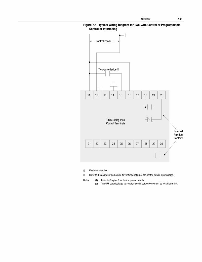
Options 7-9
Figure 7.5 Typical Wiring Diagram for Two-wire Control or Programmable Controller Interfacing
① Customer supplied.
② Refer to the controller nameplate to verify the rating of the control power input voltage.
Notes: (1) Refer to Chapter 3 for typical power circuits.(2) The OFF state leakage current for a solid-state device must be less than 6 mA.
Control Power ➁
Two-wire device ➀
11 12 13 14 15 16 17 18 19 20
21 22 23 24 25 26 27 28 29 30
Internal AuxiliaryContacts
SMC Dialog PlusControl Terminals
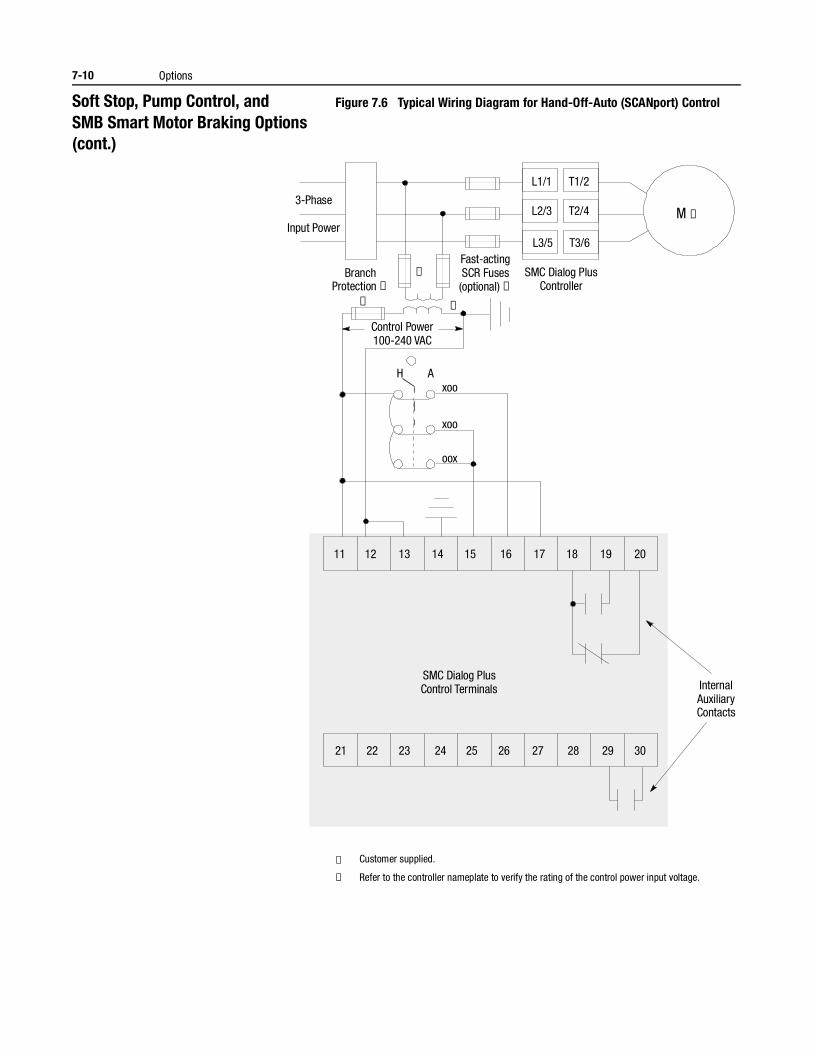
7-10 Options
Soft Stop, Pump Control, andSMB Smart Motor Braking Options (cont.)
Figure 7.6 Typical Wiring Diagram for Hand-Off-Auto (SCANport) Control
① Customer supplied.
② Refer to the controller nameplate to verify the rating of the control power input voltage.
H Axoo
xoo
oox
3-Phase
Input Power
BranchProtection ➀
Fast-actingSCR Fuses(optional) ➀
SMC Dialog PlusController
Control Power100-240 VAC
M ➀
➀
➀
➀
L1/1
L2/3
L3/5
T1/2
T2/4
T3/6
11 12 13 14 15 16 17 18 19 20
21 22 23 24 25 26 27 28 29 30
InternalAuxiliaryContacts
SMC Dialog PlusControl Terminals
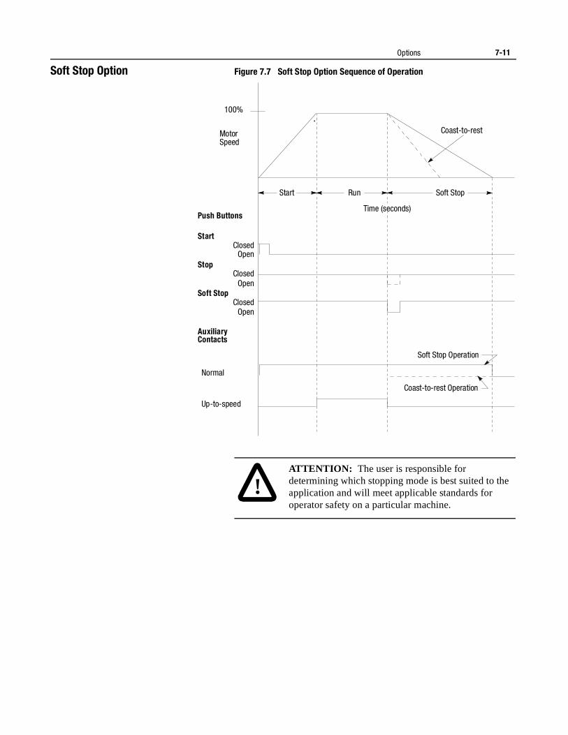
Options 7-11
Soft Stop Option Figure 7.7 Soft Stop Option Sequence of Operation
Motor Speed
Push Buttons
Start
Stop
Soft Stop
Auxiliary Contacts
Normal
Up-to-speed
Start Run
Open
Open
Open Closed
Closed
Closed
100%
Coast-to-rest
Soft Stop Operation
Coast-to-rest Operation
Soft Stop
Time (seconds)
!ATTENTION: The user is responsible for determining which stopping mode is best suited to the application and will meet applicable standards for operator safety on a particular machine.
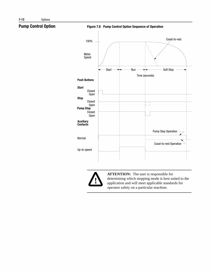
7-12 Options
Pump Control Option Figure 7.8 Pump Control Option Sequence of Operation
Motor Speed
Push Buttons
Start
Stop
Soft Stop
Auxiliary Contacts
Normal
Up-to-speed
Start Run
Open
Open
Open Closed
Closed
Closed
100% Coast-to-rest
Pump Stop Operation
Coast-to-rest Operation
Soft Stop
Time (seconds)
Pump Stop
!ATTENTION: The user is responsible for determining which stopping mode is best suited to the application and will meet applicable standards for operator safety on a particular machine.
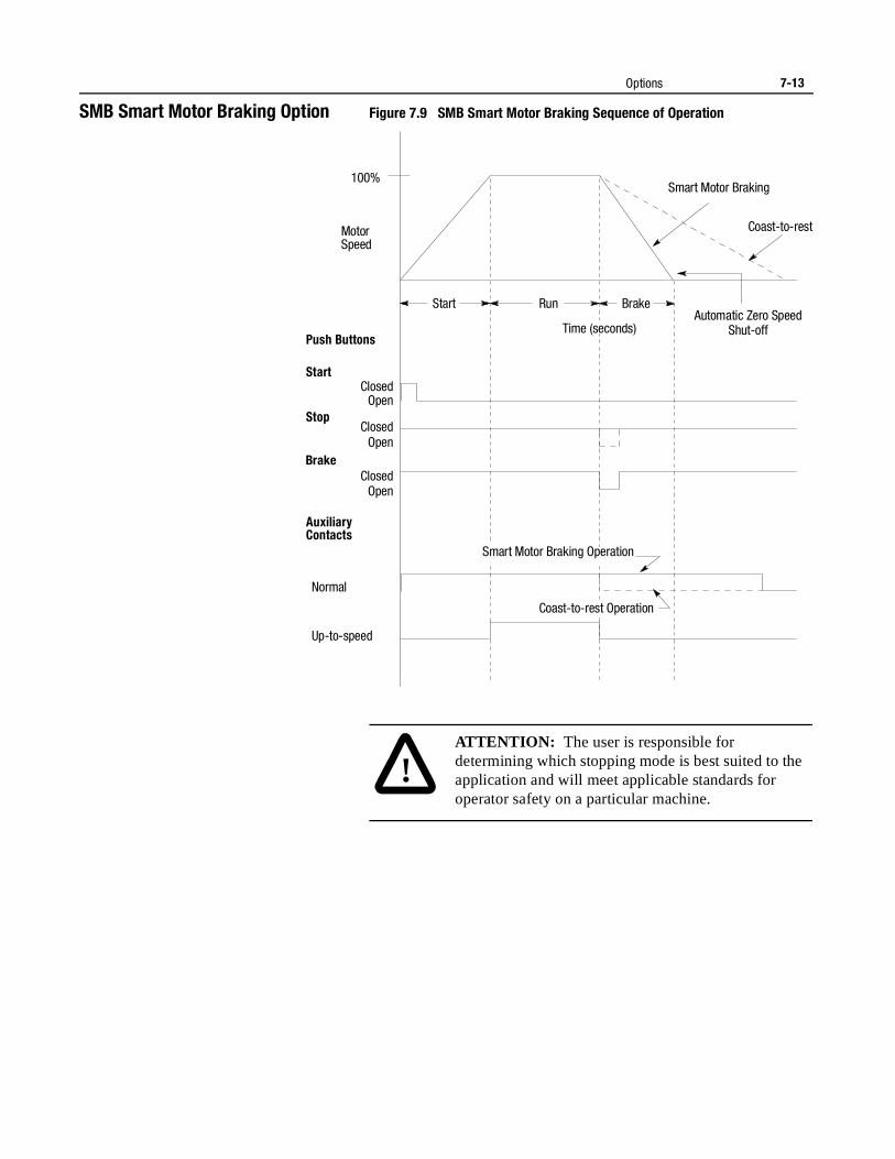
Options 7-13
SMB Smart Motor Braking Option Figure 7.9 SMB Smart Motor Braking Sequence of Operation
Motor Speed
Push Buttons
Start
Stop
Soft Stop
Auxiliary Contacts
Normal
Up-to-speed
Start Run
Open
Open
Open Closed
Closed
Closed
100%
Coast-to-rest
Automatic Zero SpeedShut-off
Smart Motor Braking
Brake
Time (seconds)
Coast-to-rest Operation
Smart Motor Braking Operation
Brake
!ATTENTION: The user is responsible for determining which stopping mode is best suited to the application and will meet applicable standards for operator safety on a particular machine.
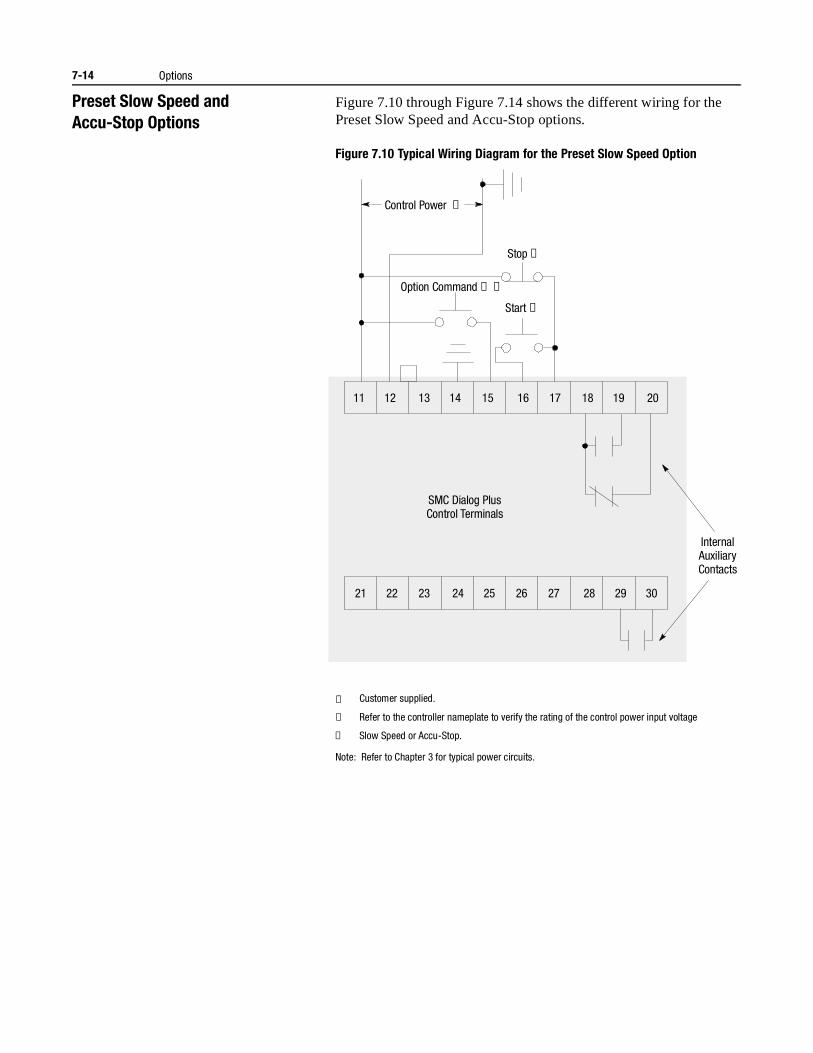
7-14 Options
Preset Slow Speed andAccu-Stop Options
Figure 7.10 through Figure 7.14 shows the different wiring for the Preset Slow Speed and Accu-Stop options.
Figure 7.10 Typical Wiring Diagram for the Preset Slow Speed Option
① Customer supplied.
② Refer to the controller nameplate to verify the rating of the control power input voltage
③ Slow Speed or Accu-Stop.
Note: Refer to Chapter 3 for typical power circuits.
Stop ➀
Control Power ➁
Option Command ➀ ➂
Start ➀
11 12 13 14 15 16 17 18 19 20
21 22 23 24 25 26 27 28 29 30
Internal AuxiliaryContacts
SMC Dialog PlusControl Terminals
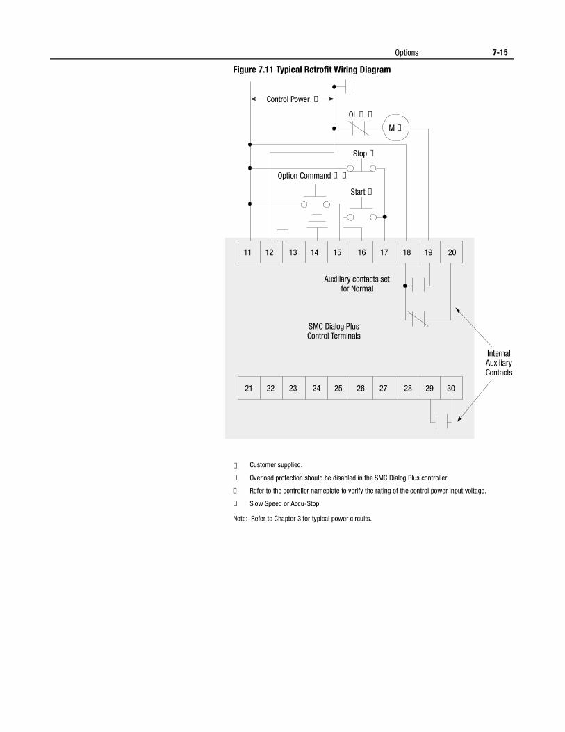
Options 7-15
Figure 7.11 Typical Retrofit Wiring Diagram
① Customer supplied.
② Overload protection should be disabled in the SMC Dialog Plus controller.
③ Refer to the controller nameplate to verify the rating of the control power input voltage.
④ Slow Speed or Accu-Stop.
Note: Refer to Chapter 3 for typical power circuits.
Stop ➀
OL ➀ ➁
M ➀
Control Power ➂
Option Command ➀ ➃
Start ➀
11 12 13 14 15 16 17 18 19 20
21 22 23 24 25 26 27 28 29 30
Internal AuxiliaryContacts
Auxiliary contacts setfor Normal
SMC Dialog PlusControl Terminals
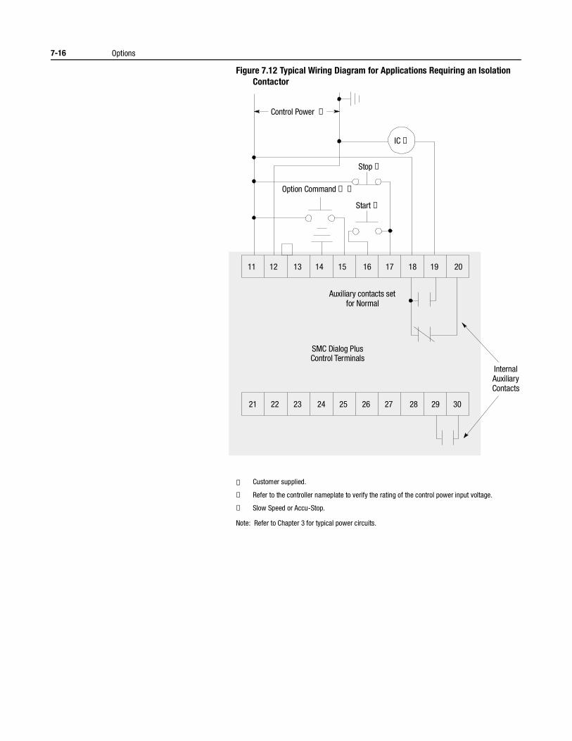
7-16 Options
Figure 7.12 Typical Wiring Diagram for Applications Requiring an Isolation Contactor
① Customer supplied.
② Refer to the controller nameplate to verify the rating of the control power input voltage.
④ Slow Speed or Accu-Stop.
Note: Refer to Chapter 3 for typical power circuits.
Stop ➀
IC ➀
Control Power ➁
Option Command ➀ ➂
Start ➀
11 12 13 14 15 16 17 18 19 20
21 22 23 24 25 26 27 28 29 30
Internal AuxiliaryContacts
Auxiliary contacts setfor Normal
SMC Dialog PlusControl Terminals
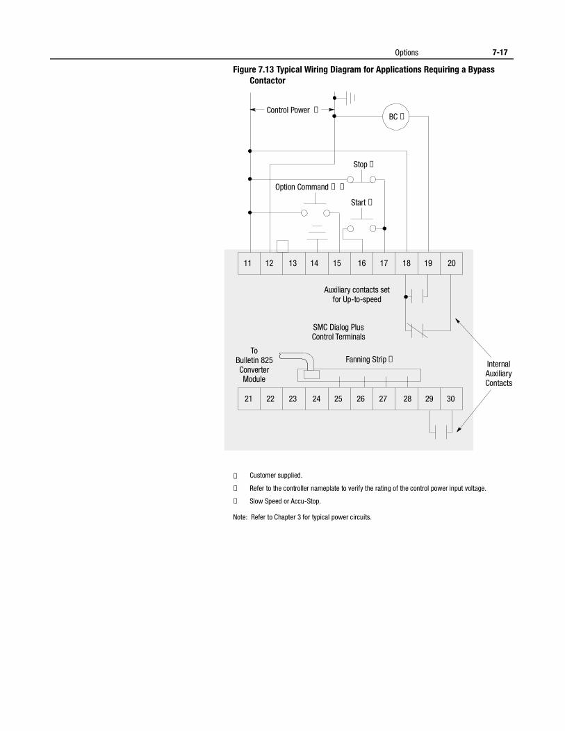
Options 7-17
Figure 7.13 Typical Wiring Diagram for Applications Requiring a Bypass Contactor
① Customer supplied.
② Refer to the controller nameplate to verify the rating of the control power input voltage.
④ Slow Speed or Accu-Stop.
Note: Refer to Chapter 3 for typical power circuits.
Stop ➀
BC ➀Control Power ➁
Option Command ➀ ➂
Start ➀
11 12 13 14 15 16 17 18 19 20
21 22 23 24 25 26 27 28 29 30
Internal AuxiliaryContacts
ToBulletin 825ConverterModule
Auxiliary contacts setfor Up-to-speed
Fanning Strip ➀
SMC Dialog PlusControl Terminals
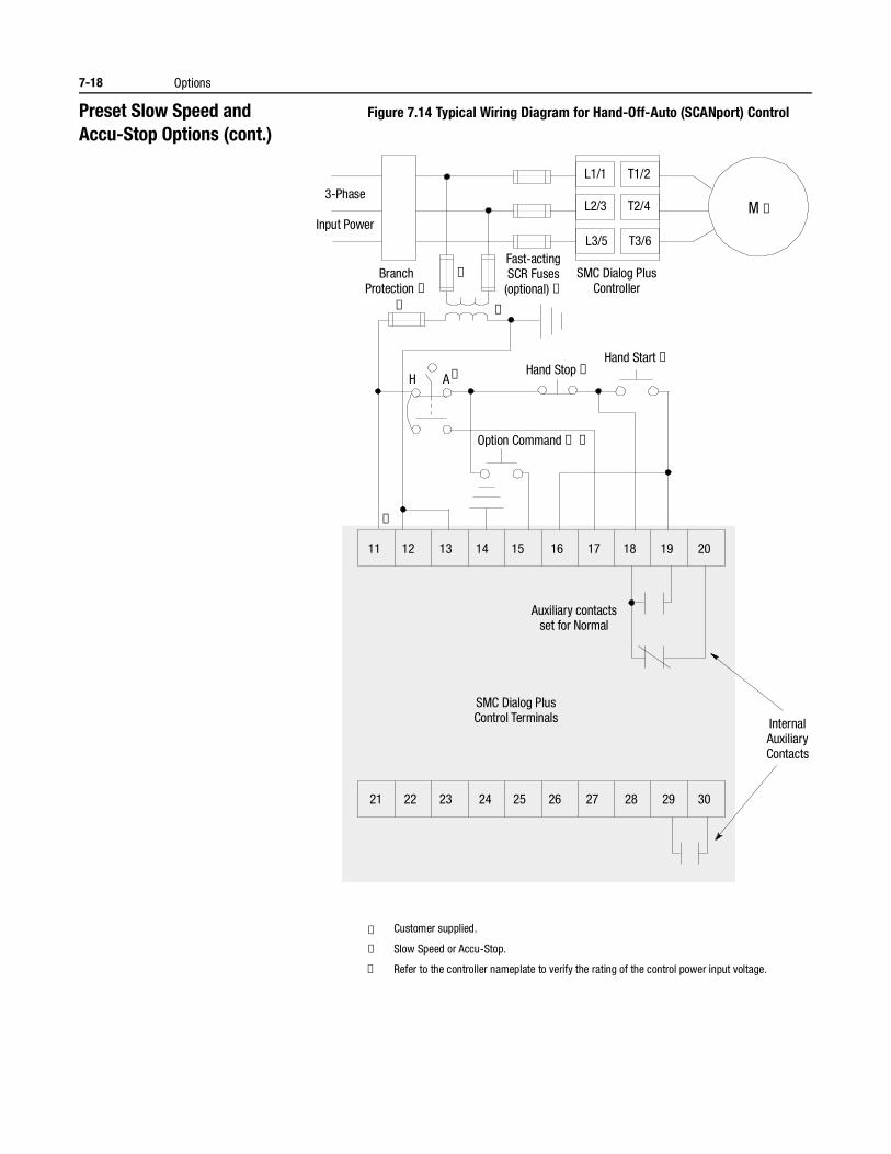
7-18 Options
Preset Slow Speed andAccu-Stop Options (cont.)
Figure 7.14 Typical Wiring Diagram for Hand-Off-Auto (SCANport) Control
① Customer supplied.
② Slow Speed or Accu-Stop.
③ Refer to the controller nameplate to verify the rating of the control power input voltage.
H A
3-Phase
Input Power
BranchProtection ➀
Hand Stop ➀Hand Start ➀
Option Command ➀ ➁
Fast-actingSCR Fuses(optional) ➀
SMC Dialog PlusController
M ➀
➀
➀
➂
➀
➀
L1/1
L2/3
L3/5
T1/2
T2/4
T3/6
11 12 13 14 15 16 17 18 19 20
21 22 23 24 25 26 27 28 29 30
InternalAuxiliaryContacts
Auxiliary contactsset for Normal
SMC Dialog PlusControl Terminals
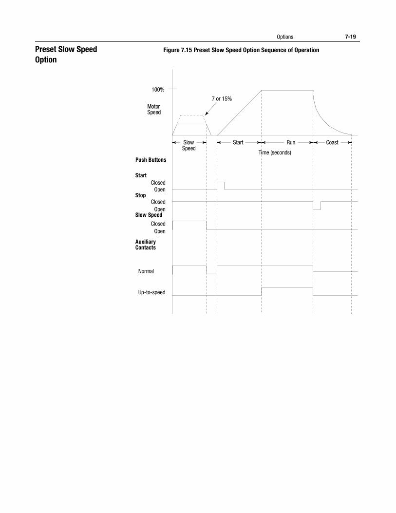
Options 7-19
Preset Slow SpeedOption
Figure 7.15 Preset Slow Speed Option Sequence of Operation
Start Coast
Motor Speed
100%
Push Buttons
Start
Stop
Slow Speed
Auxiliary Contacts
Normal
Up-to-speed
Open
Open
Open Closed
Closed
Closed
7 or 15%
Run Slow Speed
Time (seconds)
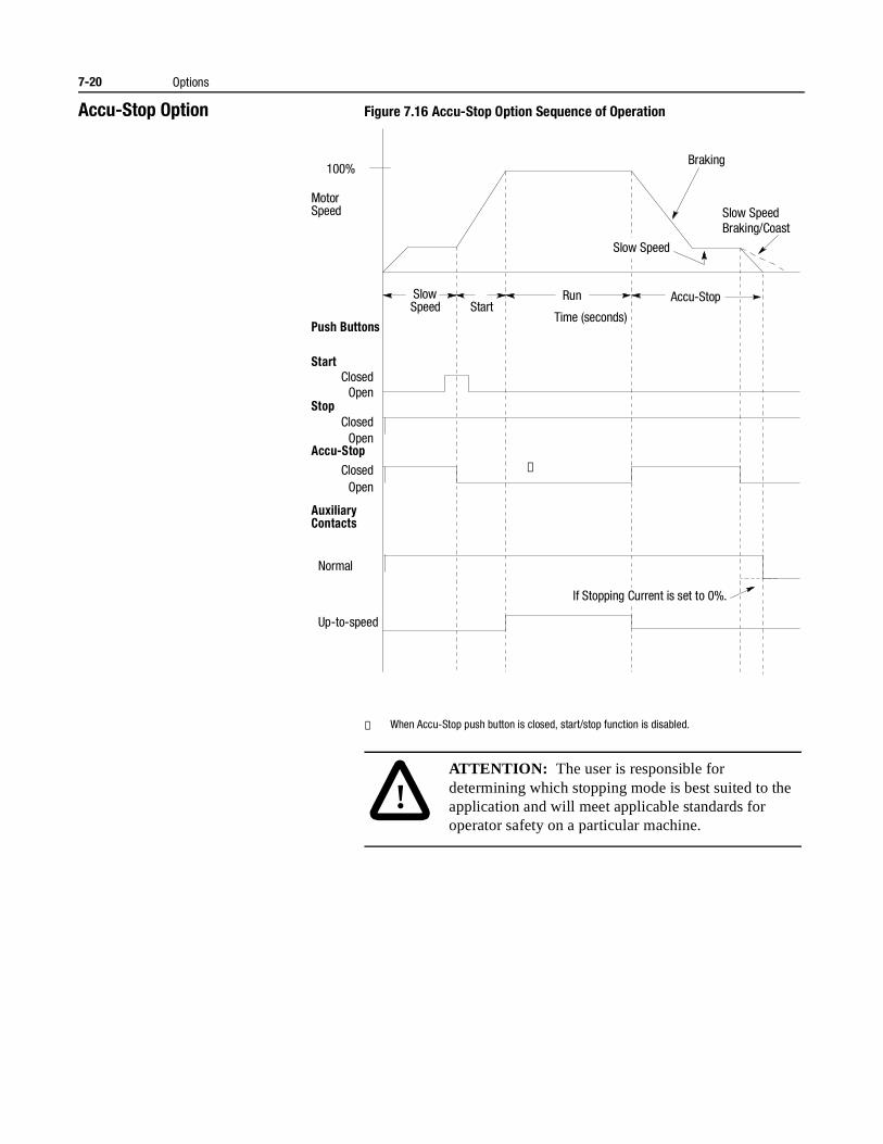
7-20 Options
Accu-Stop Option Figure 7.16 Accu-Stop Option Sequence of Operation
① When Accu-Stop push button is closed, start/stop function is disabled.
Motor Speed
100%
Push Buttons
Start
Stop
Accu-Stop
Auxiliary Contacts
Normal
Up-to-speed
Open
Open
Open Closed
Closed
Closed
Start Run Slow
Speed Accu-Stop
Braking
Slow SpeedBraking/Coast
➀
Time (seconds)
If Stopping Current is set to 0%.
Slow Speed
!ATTENTION: The user is responsible for determining which stopping mode is best suited to the application and will meet applicable standards for operator safety on a particular machine.
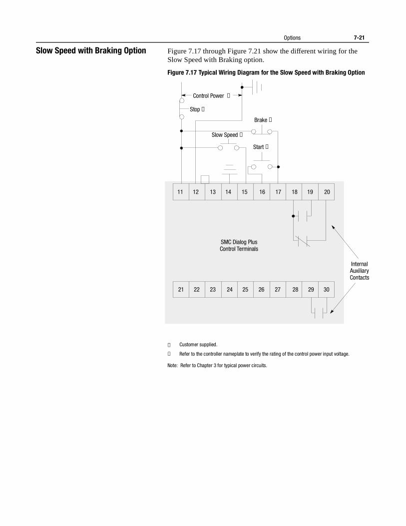
Options 7-21
Slow Speed with Braking Option Figure 7.17 through Figure 7.21 show the different wiring for the Slow Speed with Braking option.
Figure 7.17 Typical Wiring Diagram for the Slow Speed with Braking Option
① Customer supplied.
② Refer to the controller nameplate to verify the rating of the control power input voltage.
Note: Refer to Chapter 3 for typical power circuits.
Brake ➀
Stop ➀
Control Power ➁
Slow Speed ➀
Start ➀
11 12 13 14 15 16 17 18 19 20
21 22 23 24 25 26 27 28 29 30
Internal AuxiliaryContacts
SMC Dialog PlusControl Terminals
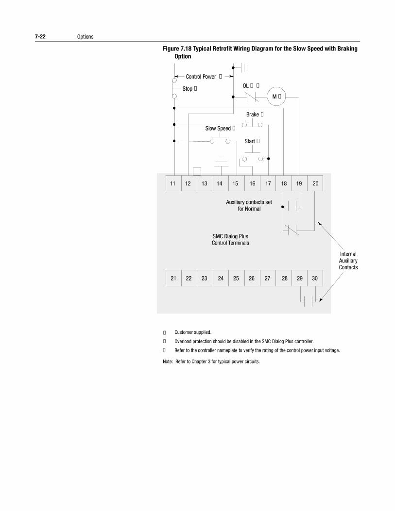
7-22 Options
Figure 7.18 Typical Retrofit Wiring Diagram for the Slow Speed with Braking Option
① Customer supplied.
② Overload protection should be disabled in the SMC Dialog Plus controller.
③ Refer to the controller nameplate to verify the rating of the control power input voltage.
Note: Refer to Chapter 3 for typical power circuits.
Brake ➀
OL ➀ ➁Stop ➀
M ➀
Control Power ➂
Slow Speed ➀
Start ➀
11 12 13 14 15 16 17 18 19 20
21 22 23 24 25 26 27 28 29 30
Internal AuxiliaryContacts
Auxiliary contacts setfor Normal
SMC Dialog PlusControl Terminals
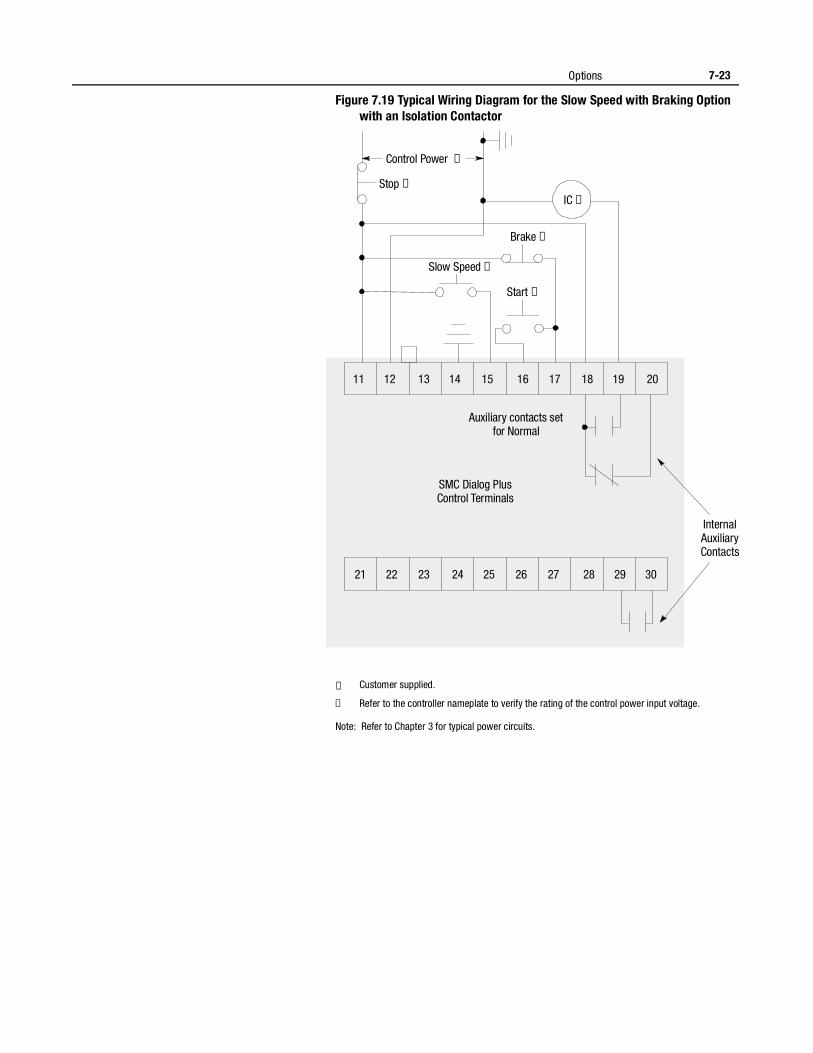
Options 7-23
Figure 7.19 Typical Wiring Diagram for the Slow Speed with Braking Option with an Isolation Contactor
① Customer supplied.
② Refer to the controller nameplate to verify the rating of the control power input voltage.
Note: Refer to Chapter 3 for typical power circuits.
Brake ➀
Stop ➀
IC ➀
Control Power ➁
Slow Speed ➀
Start ➀
11 12 13 14 15 16 17 18 19 20
21 22 23 24 25 26 27 28 29 30
Internal AuxiliaryContacts
Auxiliary contacts setfor Normal
SMC Dialog PlusControl Terminals
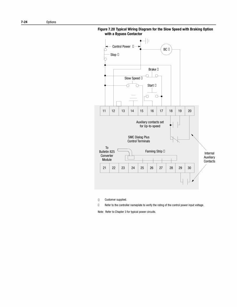
7-24 Options
Figure 7.20 Typical Wiring Diagram for the Slow Speed with Braking Option with a Bypass Contactor
① Customer supplied.
② Refer to the controller nameplate to verify the rating of the control power input voltage.
Note: Refer to Chapter 3 for typical power circuits.
Brake ➀
Stop ➀
BC ➀Control Power ➁
Slow Speed ➀
Start ➀
11 12 13 14 15 16 17 18 19 20
21 22 23 24 25 26 27 28 29 30
Internal AuxiliaryContacts
ToBulletin 825ConverterModule
Auxiliary contacts setfor Up-to-speed
Fanning Strip ➀
SMC Dialog PlusControl Terminals
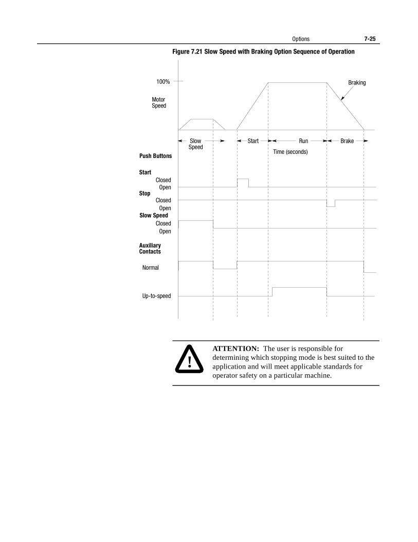
Options 7-25
Figure 7.21 Slow Speed with Braking Option Sequence of Operation
Start Brake
Motor Speed
100%
Push Buttons
Start
Stop
Slow Speed
Auxiliary Contacts
Normal
Up-to-speed
Open
Open
Open Closed
Closed
Closed
Braking
Run Slow Speed
Time (seconds)
!ATTENTION: The user is responsible for determining which stopping mode is best suited to the application and will meet applicable standards for operator safety on a particular machine.
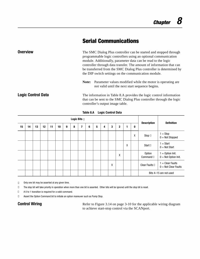
Chapter 8
Serial Communications
Overview The SMC Dialog Plus controller can be started and stopped through programmable logic controllers using an optional communication module. Additionally, parameter data can be read to the logic controller through data transfer. The amount of information that can be transferred from the SMC Dialog Plus controller is determined by the DIP switch settings on the communication module.
Note: Parameter values modified while the motor is operating are not valid until the next start sequence begins.
Logic Control Data The information in Table 8.A provides the logic control information that can be sent to the SMC Dialog Plus controller through the logic controller’s output image table.
Table 8.A Logic Control Data
① Only one bit may be asserted at any given time.
② The stop bit will take priority in operation when more than one bit is asserted. Other bits will be ignored until the stop bit is reset.
③ A 0 to 1 transition is required for a valid command.
④ Assert the Option Command bit to initiate an option maneuver such as Pump Stop.
Control Wiring Refer to Figure 3.14 on page 3-10 for the applicable wiring diagram to achieve start-stop control via the SCANport.
Logic Bits ①Description Definition
15 14 13 12 11 10 9 8 7 6 5 4 3 2 1 0
X Stop ②1 = Stop0 = Not Stopped
X Start ③1 = Start0 = Not Start
XOption
Command ④
1 = Option Init.0 = Not Option Init.
X Clear Faults ③1 = Clear Faults0 = Not Clear Faults
Bits 4–15 are not used
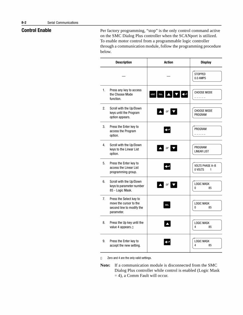
8-2 Serial Communications
Control Enable Per factory programming, “stop” is the only control command active on the SMC Dialog Plus controller when the SCANport is utilized. To enable motor control from a programmable logic controller through a communication module, follow the programming procedure below.
① Zero and 4 are the only valid settings.
Note: If a communication module is disconnected from the SMC Dialog Plus controller while control is enabled (Logic Mask = 4), a Comm Fault will occur.
Description Action Display
— —
1. Press any key to access the Choose Mode function.
2. Scroll with the Up/Down keys until the Program option appears.
3. Press the Enter key to access the Program option.
4. Scroll with the Up/Down keys to the Linear List option.
5. Press the Enter key to access the Linear List programming group.
6. Scroll with the Up/Down keys to parameter number 85 - Logic Mask.
7. Press the Select key to move the cursor to the second line to modify the parameter.
8. Press the Up key until the value 4 appears.①
9. Press the Enter key to accept the new setting.
STOPPED0.0 AMPS
CHOOSE MODE_ _ _ _ _
or CHOOSE MODEPROGRAM
PROGRAM_ _ _ _ _
or PROGRAMLINEAR LIST
VOLTS PHASE A–B0 VOLTS 1
or LOGIC MASK0 85
LOGIC MASK0 85
LOGIC MASK4 85
LOGIC MASK4 85

Serial Communications 8-3
SMC Status Data The information in Table 8.B provides the SMC Dialog Plus controller status information that can be sent to the logic controller’s input image table.
Table 8.B SMC Status Data
① When control power is applied, this bit is always set to 1.
Reference/Feedback The SMC Dialog Plus controller does not support the analog reference feature of SCANport. The SCANport analog feedback feature, however, is supported. The feedback word will always be equal to Parameter number 4, Current Phase A.
Parameter Listing Refer to Appendix B, Table B.1 for a complete listing of the SMC Dialog Plus controller’s parameters and groups. In addition to the range of adjustments, the parameters’ units are provided.
Scale FactorConversion
The parameter values of the SMC Dialog Plus controller are stored as unscaled numbers. When reading parameter data in the PLC/SLC’s input image table, divide this number by the scale factor shown in Appendix B, Table B.1 to arrive at the proper value.
When writing from the PLC/SLC’s output image table to the SMC Dialog Plus controller, the scale factor must be taken into consideration to ensure that the proper value is sent.
Logic BitsDescription Definition
15 14 13 12 11 10 9 8 7 6 5 4 3 2 1 0
X Enabled ①1 = Enabled0 = Not Enabled
X Running1 = Running0 = Not Running
Not Used —
Not Used —
X Starting1 = Starting0 = Not Starting
X Stopping1 = Stopping0 = Not Stopping
X Fault1 = Faulted0 = Not Faulted
X At Speed1 = At Speed0 = Not at Speed
Bits 9–15 are not used
8-4 Serial Communications
Display UnitEquivalents
Some parameter setting options use a text description when viewed from the built-in LCD display or a human interface module. An example is the parameter, Starting Mode, which has the available settings of Soft Start and Current Limit. Table B.2, found in Appendix B provides the required display unit decimal equivalent for use when sending a command from a logic controller to the SMC Dialog Plus controller.
Datalinks The SMC Dialog Plus controller does not offer Datalinks.
Interfacing Refer to the appropriate communication module manual for detailed information regarding communication module installation, DIP switch settings, block transfer instructions, and communication module troubleshooting.
Processing Time The typical time for the SMC Dialog Plus controller to process a single parameter data request (i.e., block transfer) via the SCANport is approximately 100 msec. Keep this value in mind when determining the message length of multiple parameter value read or write operations.
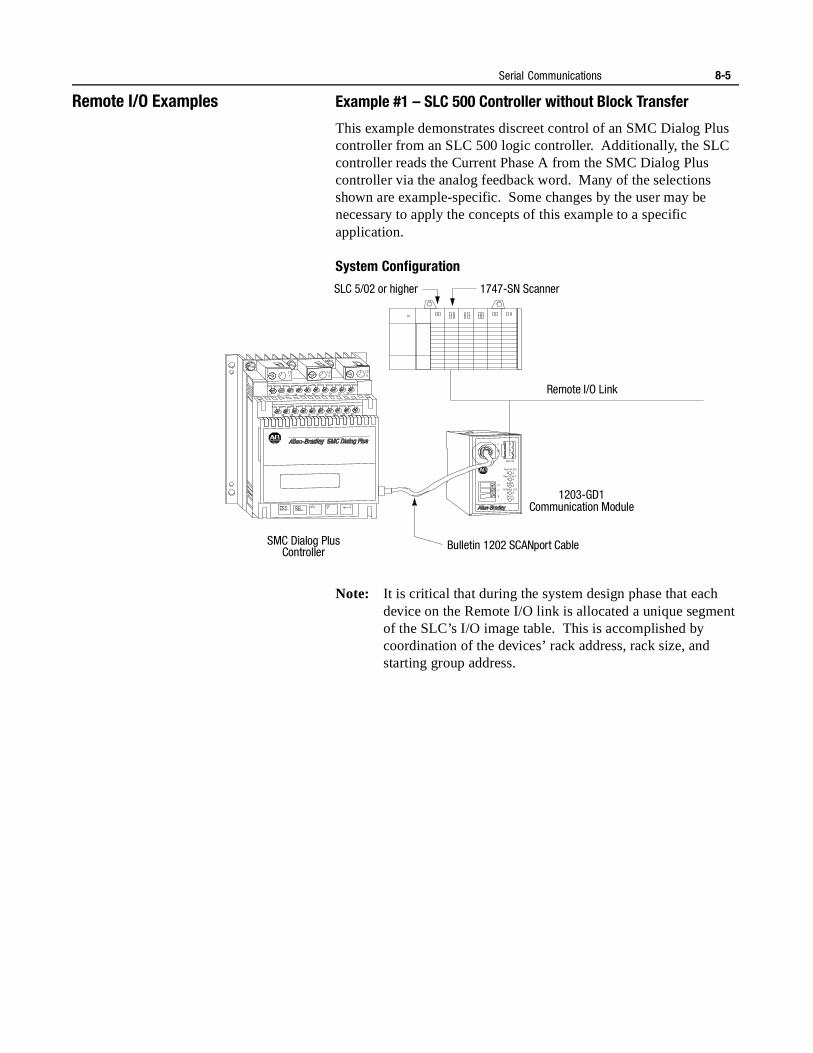
Serial Communications 8-5
Remote I/O Examples Example #1 – SLC 500 Controller without Block Transfer
This example demonstrates discreet control of an SMC Dialog Plus controller from an SLC 500 logic controller. Additionally, the SLC controller reads the Current Phase A from the SMC Dialog Plus controller via the analog feedback word. Many of the selections shown are example-specific. Some changes by the user may be necessary to apply the concepts of this example to a specific application.
System Configuration
Note: It is critical that during the system design phase that each device on the Remote I/O link is allocated a unique segment of the SLC’s I/O image table. This is accomplished by coordination of the devices’ rack address, rack size, and starting group address.
SLC 5/02 or higher 1747-SN Scanner
Remote I/O Link
SMC Dialog Plus Controller
1203-GD1
Re m I/O
Re m I/O STS
Re m I/O AC T
H ea lth
SC AN bus STS
FA ULT
2
SH
1
V+
V-
L11
L23
L35
11
21
12
22
13
23
14
24
15
25
16
26
17
27
18
28
19
29
20
30
G
Communication Module
Bulletin 1202 SCANport Cable
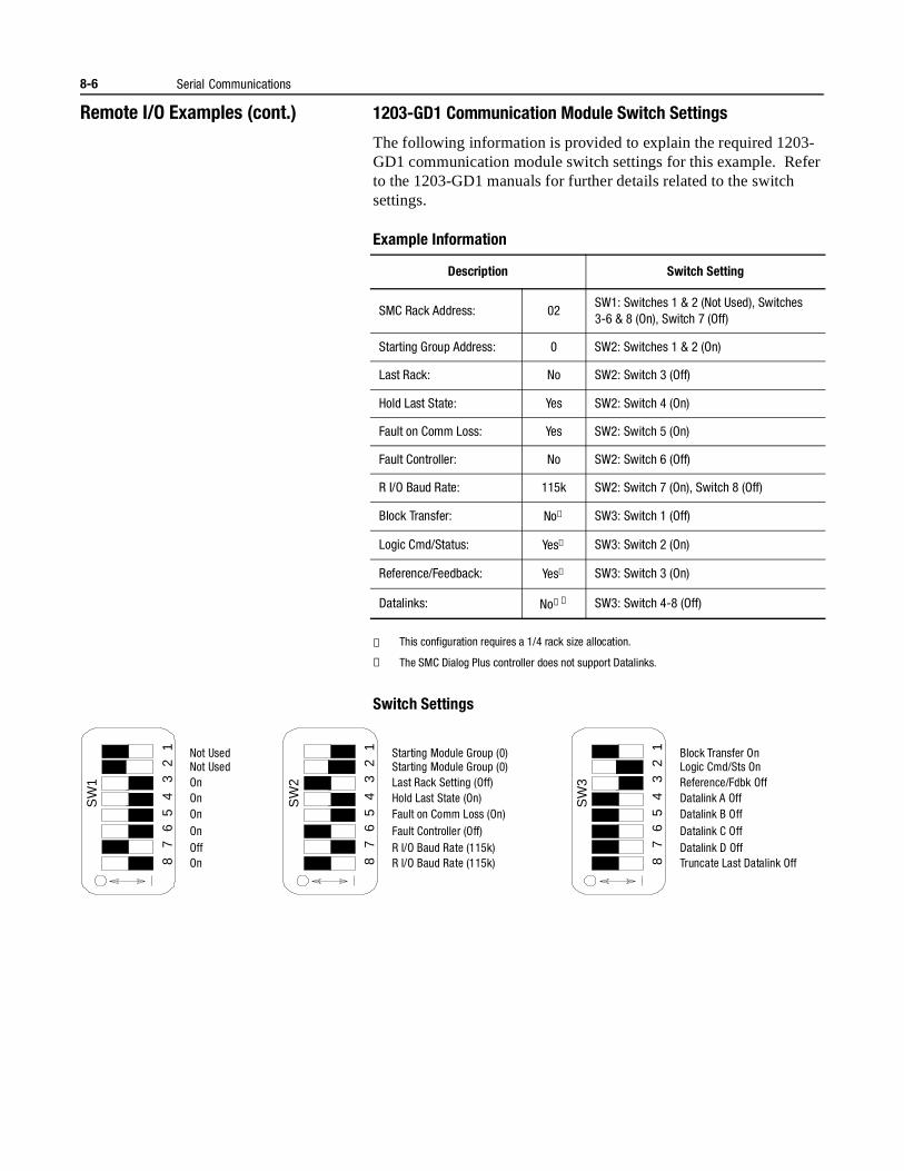
8-6 Serial Communications
Remote I/O Examples (cont.) 1203-GD1 Communication Module Switch Settings
The following information is provided to explain the required 1203-GD1 communication module switch settings for this example. Refer to the 1203-GD1 manuals for further details related to the switch settings.
Example Information
① This configuration requires a 1/4 rack size allocation.
② The SMC Dialog Plus controller does not support Datalinks.
Switch Settings
Description Switch Setting
SMC Rack Address: 02SW1: Switches 1 & 2 (Not Used), Switches 3-6 & 8 (On), Switch 7 (Off)
Starting Group Address: 0 SW2: Switches 1 & 2 (On)
Last Rack: No SW2: Switch 3 (Off)
Hold Last State: Yes SW2: Switch 4 (On)
Fault on Comm Loss: Yes SW2: Switch 5 (On)
Fault Controller: No SW2: Switch 6 (Off)
R I/O Baud Rate: 115k SW2: Switch 7 (On), Switch 8 (Off)
Block Transfer: No① SW3: Switch 1 (Off)
Logic Cmd/Status: Yes① SW3: Switch 2 (On)
Reference/Feedback: Yes① SW3: Switch 3 (On)
Datalinks: No①② SW3: Switch 4-8 (Off)
SW
1
8 7
6 5
4 3
2 1 Not Used
Not Used On On On On Off On
SW
2
8 7
6 5
4 3
2 1 Starting Module Group (0)
Starting Module Group (0) Last Rack Setting (Off) Hold Last State (On) Fault on Comm Loss (On) Fault Controller (Off) R I/O Baud Rate (115k) R I/O Baud Rate (115k)
SW
3
8 7
6 5
4 3
2 1 Block Transfer On
Logic Cmd/Sts On Reference/Fdbk Off Datalink A Off Datalink B Off Datalink C Off Datalink D Off Truncate Last Datalink Off
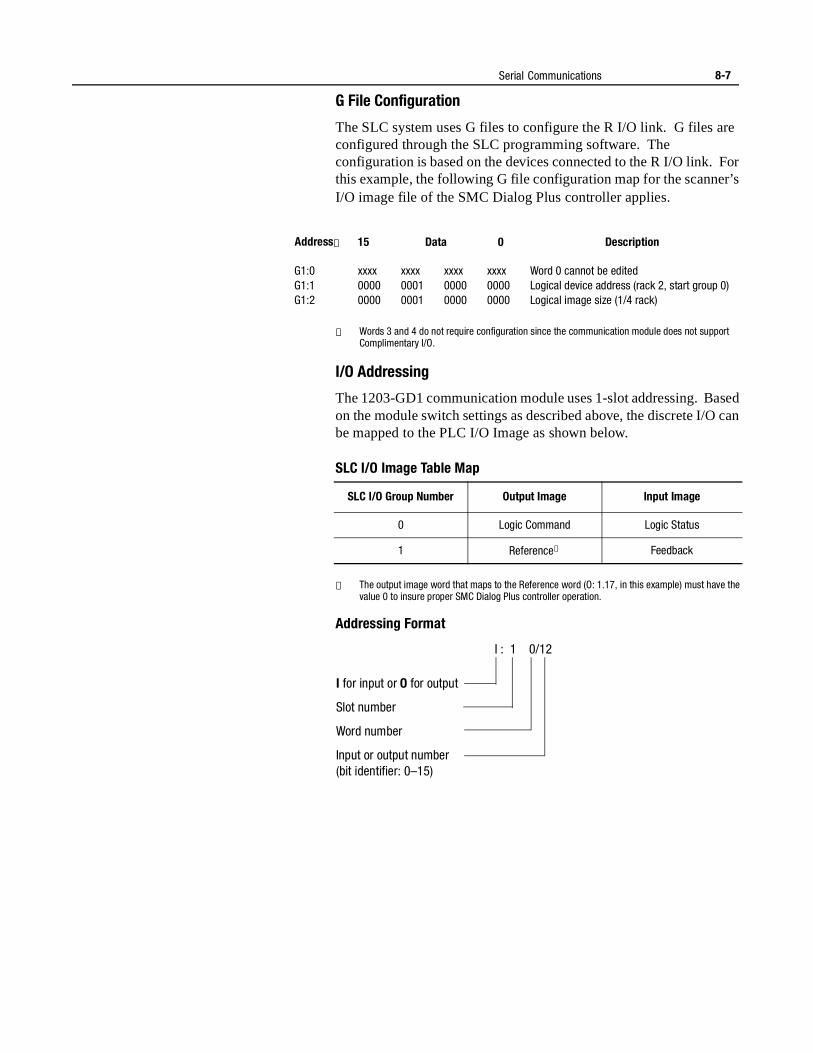
Serial Communications 8-7
G File Configuration
The SLC system uses G files to configure the R I/O link. G files are configured through the SLC programming software. The configuration is based on the devices connected to the R I/O link. For this example, the following G file configuration map for the scanner’s I/O image file of the SMC Dialog Plus controller applies.
① Words 3 and 4 do not require configuration since the communication module does not support Complimentary I/O.
I/O Addressing
The 1203-GD1 communication module uses 1-slot addressing. Based on the module switch settings as described above, the discrete I/O can be mapped to the PLC I/O Image as shown below.
SLC I/O Image Table Map
① The output image word that maps to the Reference word (O: 1.17, in this example) must have the value 0 to insure proper SMC Dialog Plus controller operation.
Addressing Format
Address① 15 Data 0 Description
G1:0G1:1G1:2
xxxx00000000
xxxx00010001
xxxx00000000
xxxx00000000
Word 0 cannot be editedLogical device address (rack 2, start group 0)Logical image size (1/4 rack)
SLC I/O Group Number Output Image Input Image
0 Logic Command Logic Status
1 Reference① Feedback
I for input or O for output
Slot number
Word number
Input or output number(bit identifier: 0–15)
I : 1 0/12
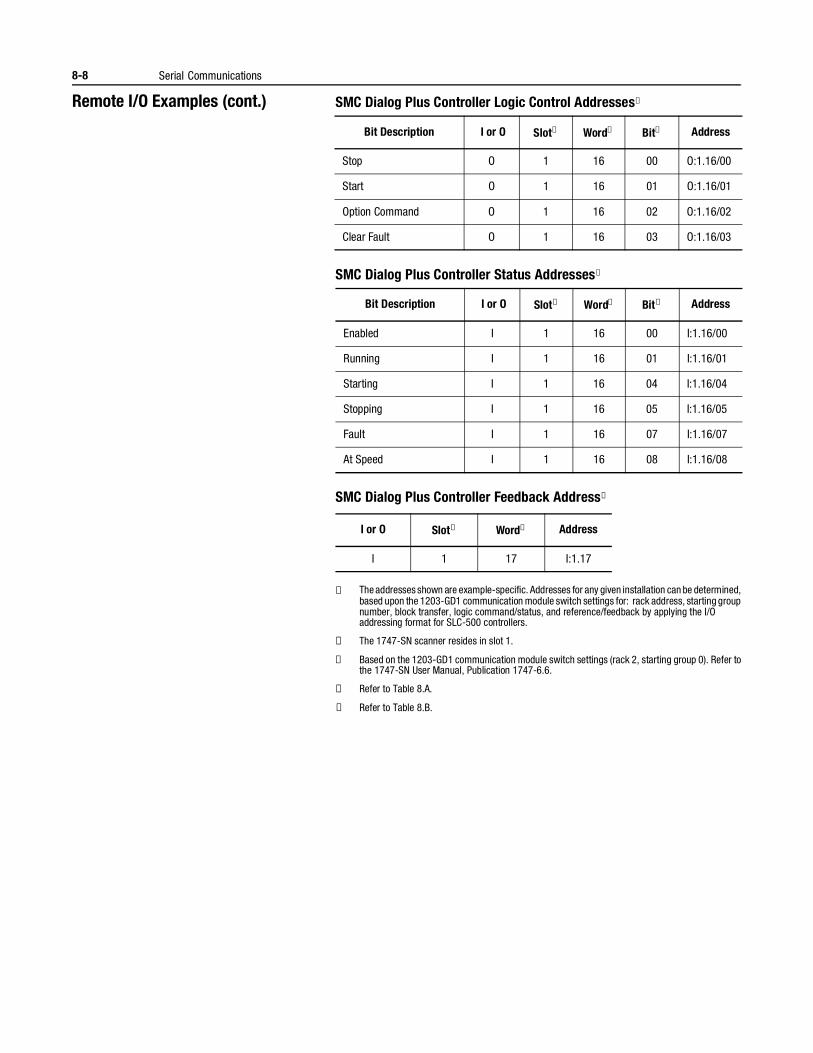
8-8 Serial Communications
Remote I/O Examples (cont.) SMC Dialog Plus Controller Logic Control Addresses①
SMC Dialog Plus Controller Status Addresses①
SMC Dialog Plus Controller Feedback Address①
① The addresses shown are example-specific. Addresses for any given installation can be determined, based upon the 1203-GD1 communication module switch settings for: rack address, starting group number, block transfer, logic command/status, and reference/feedback by applying the I/O addressing format for SLC-500 controllers.
② The 1747-SN scanner resides in slot 1.
③ Based on the 1203-GD1 communication module switch settings (rack 2, starting group 0). Refer to the 1747-SN User Manual, Publication 1747-6.6.
④ Refer to Table 8.A.
⑤ Refer to Table 8.B.
Bit Description I or O Slot② Word③ Bit④ Address
Stop O 1 16 00 O:1.16/00
Start O 1 16 01 O:1.16/01
Option Command O 1 16 02 O:1.16/02
Clear Fault O 1 16 03 O:1.16/03
Bit Description I or O Slot② Word③ Bit⑤ Address
Enabled I 1 16 00 I:1.16/00
Running I 1 16 01 I:1.16/01
Starting I 1 16 04 I:1.16/04
Stopping I 1 16 05 I:1.16/05
Fault I 1 16 07 I:1.16/07
At Speed I 1 16 08 I:1.16/08
I or O Slot② Word③ Address
I 1 17 I:1.17
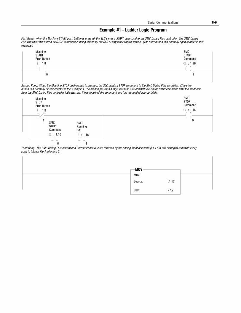
Serial Communications 8-9
Example #1 - Ladder Logic Program
Machine START Push Button
: 1.8
SMC START Command
: 1.16
0 1
Machine STOP Push Button
: 1.8
SMC STOP Command
: 1.16
First Rung: When the Machine START push button is pressed, the SLC sends a START command to the SMC Dialog Plus controller. The SMC Dialog Plus controller will start if no STOP command is being issued by the SLC or any other control device. (The start button is a normally open contact in this example.)
0 1
0
Second Rung: When the Machine STOP push button is pressed, the SLC sends a STOP command to the SMC Dialog Plus controller. (The stop button is a normally closed contact in this example.) The branch provides a logic latched" circuit which exerts the STOP command until the feedback from the SMC Dialog Plus controller indicates that it has received the command and has responded appropriately.
SMC STOP
Command
: 1.16
SMC Running Bit
: 1.16
1
Third Rung: The SMC Dialog Plus controller's Current Phase A value returned by the analog feedback word (I:1.17 in this example) is moved every scan to integer file 7, element 2.
MOVE
Source:
Dest:
MOV
I:1.17
N7:2
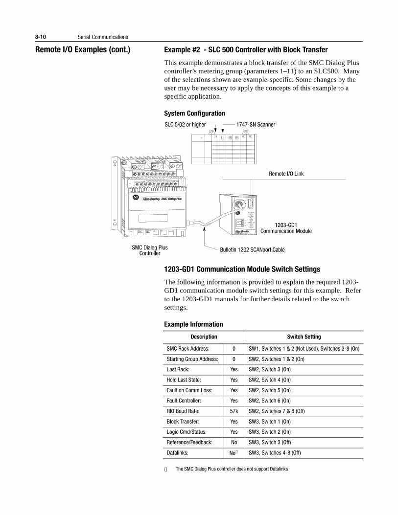
8-10 Serial Communications
Remote I/O Examples (cont.) Example #2 - SLC 500 Controller with Block Transfer
This example demonstrates a block transfer of the SMC Dialog Plus controller’s metering group (parameters 1–11) to an SLC500. Many of the selections shown are example-specific. Some changes by the user may be necessary to apply the concepts of this example to a specific application.
System Configuration
1203-GD1 Communication Module Switch Settings
The following information is provided to explain the required 1203-GD1 communication module switch settings for this example. Refer to the 1203-GD1 manuals for further details related to the switch settings.
Example Information
① The SMC Dialog Plus controller does not support Datalinks
SLC 5/02 or higher 1747-SN Scanner
Remote I/O Link
SMC Dialog Plus Controller
1203-GD1
Re m I/O
Re m I/O STS
Re m I/O AC T
H ea lth
SC AN bus STS
FA ULT
2
SH
1
V+
V-
L11
L23
L35
11
21
12
22
13
23
14
24
15
25
16
26
17
27
18
28
19
29
20
30
G
Communication Module
Bulletin 1202 SCANport Cable
Description Switch Setting
SMC Rack Address: 0 SW1, Switches 1 & 2 (Not Used), Switches 3-8 (On)
Starting Group Address: 0 SW2, Switches 1 & 2 (On)
Last Rack: Yes SW2, Switch 3 (On)
Hold Last State: Yes SW2, Switch 4 (On)
Fault on Comm Loss: Yes SW2, Switch 5 (On)
Fault Controller: Yes SW2, Switch 6 (On)
RIO Baud Rate: 57k SW2, Switches 7 & 8 (Off)
Block Transfer: Yes SW3, Switch 1 (On)
Logic Cmd/Status: Yes SW3, Switch 2 (On)
Reference/Feedback: No SW3, Switch 3 (Off)
Datalinks: No① SW3, Switches 4-8 (Off)
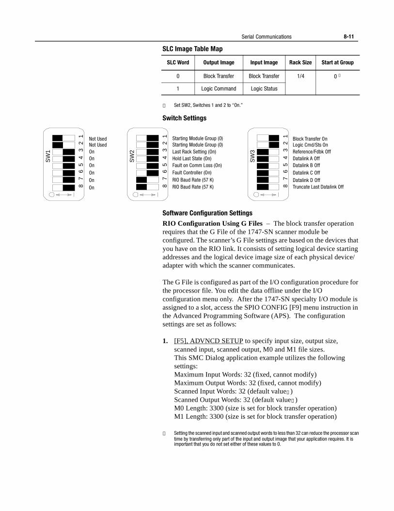
Serial Communications 8-11
SLC Image Table Map
① Set SW2, Switches 1 and 2 to “On.”
Switch Settings
Software Configuration Settings
RIO Configuration Using G Files – The block transfer operation requires that the G File of the 1747-SN scanner module be configured. The scanner’s G File settings are based on the devices that you have on the RIO link. It consists of setting logical device starting addresses and the logical device image size of each physical device/adapter with which the scanner communicates.
The G File is configured as part of the I/O configuration procedure for the processor file. You edit the data offline under the I/O configuration menu only. After the 1747-SN specialty I/O module is assigned to a slot, access the SPIO CONFIG [F9] menu instruction in the Advanced Programming Software (APS). The configuration settings are set as follows:
1. [F5], ADVNCD SETUP to specify input size, output size, scanned input, scanned output, M0 and M1 file sizes.This SMC Dialog application example utilizes the following settings:Maximum Input Words: 32 (fixed, cannot modify)Maximum Output Words: 32 (fixed, cannot modify)Scanned Input Words: 32 (default value①)Scanned Output Words: 32 (default value①)M0 Length: 3300 (size is set for block transfer operation)M1 Length: 3300 (size is set for block transfer operation)
① Setting the scanned input and scanned output words to less than 32 can reduce the processor scan time by transferring only part of the input and output image that your application requires. It is important that you do not set either of these values to 0.
SLC Word Output Image Input Image Rack Size Start at Group
0 Block Transfer Block Transfer 1/4 0 ①
1 Logic Command Logic Status
SW
2
8 7
6 5
4 3
2 1 Starting Module Group (0)
Starting Module Group (0) Last Rack Setting (On) Hold Last State (On) Fault on Comm Loss (On) Fault Controller (On) RIO Baud Rate (57 K) RIO Baud Rate (57 K)
SW
1
8 7
6 5
4 3
2 1 Not Used
Not Used On On On On On On
SW
3
8 7
6 5
4 3
2 1 Block Transfer On
Logic Cmd/Sts On Reference/Fdbk Off Datalink A Off Datalink B Off Datalink C Off Datalink D Off Truncate Last Datalink Off
8-12 Serial Communications
Remote I/O Examples (cont.) 2. [F7], G FILE SIZE to specify the number of words required for the I/O module, 3 for standard operation, 5 if using complemen-tary I/O. (In this application example, G File size = 3.)
3. [F6], MODIFY G FILEWord 0 of the G File is configured automatically by the processor according to the particular specialty I/O module. Word 0 cannot be edited.
Word 1, Primary/Normal Logical Device Address — Specifies the logical starting address of each primary/normal RIO link device. The logical address consists of the logical rack number (0, 1, 2, or 3) and starting logical group (0, 2, 4, or 6). Each bit in this word represents a logical address. To specify an address (in binary mode), you place a 1 at the bit corresponding to the starting logical address of each logical device. (For this SMC Dialog example application, Word G1/16 = 1, indicating logical rack 0, starting group 0.)
Word 2, Primary/Normal Device Logical Image Size — Specifies the logical image size (amount of scanner I/O image) of the devices set in Word 1. As with Word 1, these bits correspond to RIO logical rack and logical group numbers. To specify image size (in binary mode), you place a 1 at each group a device occupies. (This SMC Dialog example is using 1/4 rack size, Word G1/33 = 1.)
Word 3 and Word 4 refer to Complementary I/O Configuration (if G File size is set to 5), which is not used in this sample application. Please reference the RIO Scanner User Manual (Publication 1747-6.6) and the Advanced Programming Software (APS) User Manual (Publication 1746-6.4) for further information on any of the above settings or operations.
SLC 500 Ladder Logic Program
Terms used:BTBlock TransferBTR Block Transfer ReadBTW Block Transfer Write
The sample ladder logic program that follows performs a consecutive parameter value read of the SMC Dialog Plus controller’s metering group (parameters 1–11) by using a BTW/BTR pair. The BTW operation defines to the Bulletin 1203 communication module the type of parameter read/write operation (“Continuous Parameter Value Read” for this example) and identifies the parameters to be polled. Execution of the BTR operation allows the communication module to respond, providing the requested data.
Notes: (1) The ladder logic program does not contain error checking and handling. Refer to the SLC 500 and 1747-SN scanner manuals for this documentation.
(2) For this example, Allen-Bradley’s APS programming software is used.
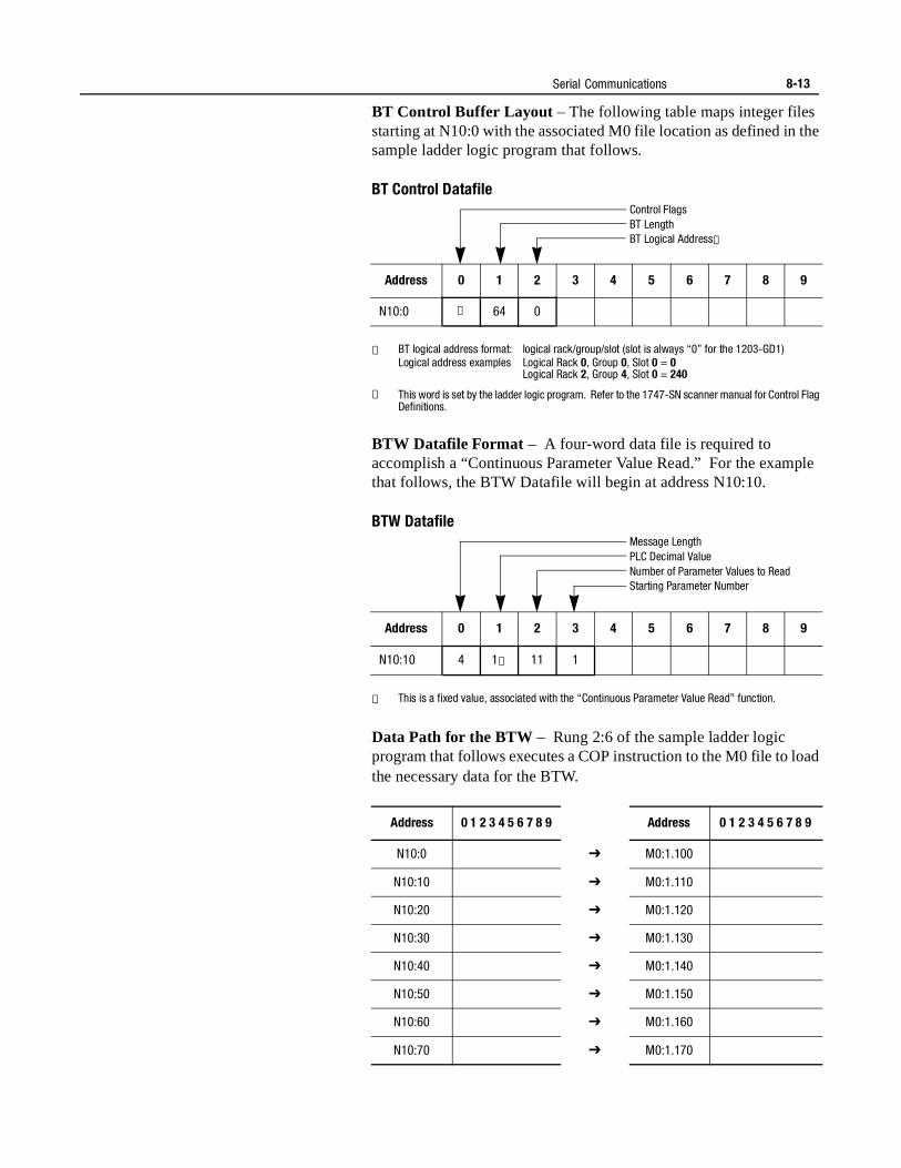
Serial Communications 8-13
BT Control Buffer Layout – The following table maps integer files starting at N10:0 with the associated M0 file location as defined in the sample ladder logic program that follows.
BT Control Datafile
① BT logical address format: logical rack/group/slot (slot is always “0” for the 1203-GD1)Logical address examples Logical Rack 0, Group 0, Slot 0 = 0
Logical Rack 2, Group 4, Slot 0 = 240
② This word is set by the ladder logic program. Refer to the 1747-SN scanner manual for Control Flag Definitions.
BTW Datafile Format – A four-word data file is required to accomplish a “Continuous Parameter Value Read.” For the example that follows, the BTW Datafile will begin at address N10:10.
BTW Datafile
① This is a fixed value, associated with the “Continuous Parameter Value Read” function.
Data Path for the BTW – Rung 2:6 of the sample ladder logic program that follows executes a COP instruction to the M0 file to load the necessary data for the BTW.
Address 0 1 2 3 4 5 6 7 8 9
N10:0 ② 64 0
Address 0 1 2 3 4 5 6 7 8 9
N10:10 4 1① 11 1
Address 0 1 2 3 4 5 6 7 8 9 Address 0 1 2 3 4 5 6 7 8 9
N10:0 £ M0:1.100
N10:10 £ M0:1.110
N10:20 £ M0:1.120
N10:30 £ M0:1.130
N10:40 £ M0:1.140
N10:50 £ M0:1.150
N10:60 £ M0:1.160
N10:70 £ M0:1.170
Control FlagsBT LengthBT Logical Address①
Message LengthPLC Decimal ValueNumber of Parameter Values to ReadStarting Parameter Number
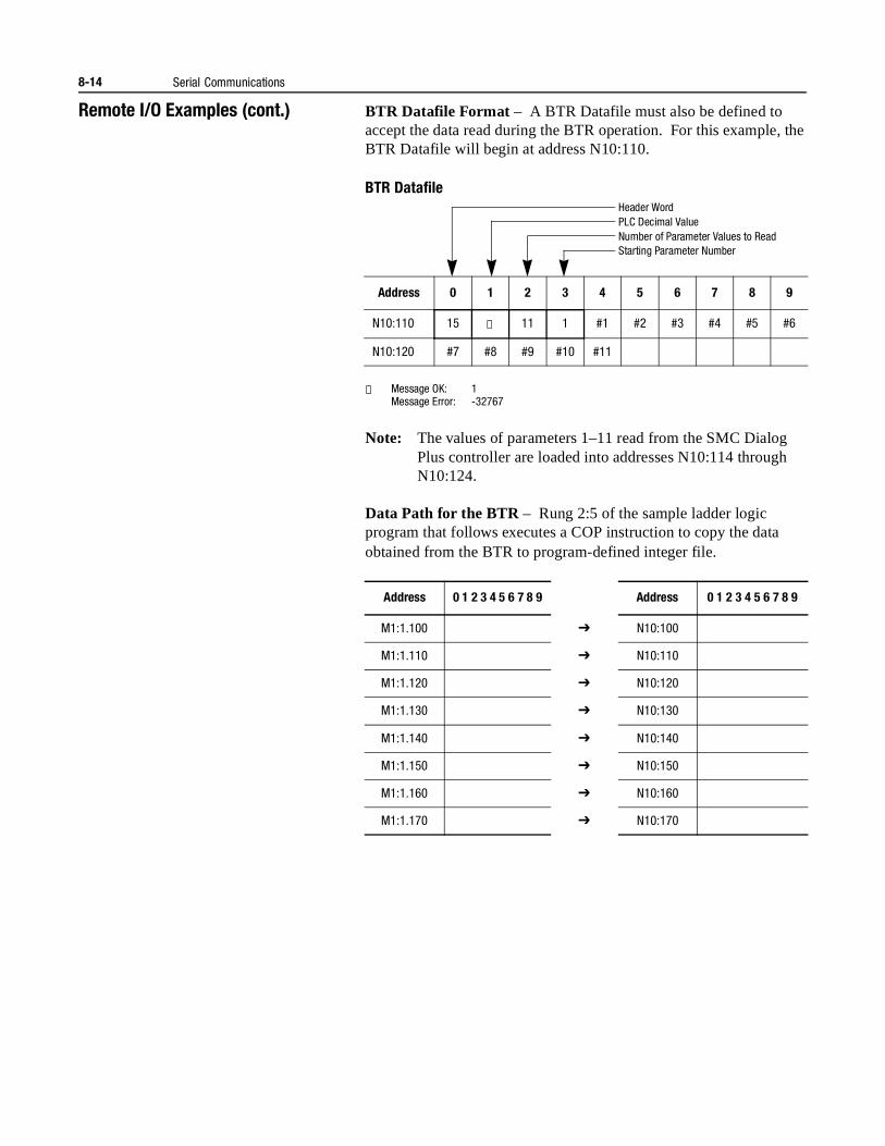
8-14 Serial Communications
Remote I/O Examples (cont.) BTR Datafile Format – A BTR Datafile must also be defined to accept the data read during the BTR operation. For this example, the BTR Datafile will begin at address N10:110.
BTR Datafile
① Message OK: 1Message Error: -32767
Note: The values of parameters 1–11 read from the SMC Dialog Plus controller are loaded into addresses N10:114 through N10:124.
Data Path for the BTR – Rung 2:5 of the sample ladder logic program that follows executes a COP instruction to copy the data obtained from the BTR to program-defined integer file.
Address 0 1 2 3 4 5 6 7 8 9
N10:110 15 ① 11 1 #1 #2 #3 #4 #5 #6
N10:120 #7 #8 #9 #10 #11
Address 0 1 2 3 4 5 6 7 8 9 Address 0 1 2 3 4 5 6 7 8 9
M1:1.100 £ N10:100
M1:1.110 £ N10:110
M1:1.120 £ N10:120
M1:1.130 £ N10:130
M1:1.140 £ N10:140
M1:1.150 £ N10:150
M1:1.160 £ N10:160
M1:1.170 £ N10:170
Header WordPLC Decimal ValueNumber of Parameter Values to ReadStarting Parameter Number
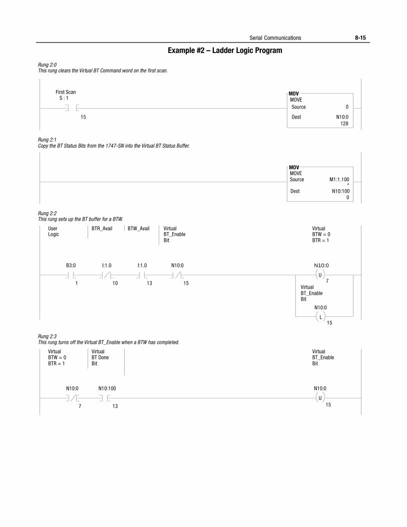
Serial Communications 8-15
Example #2 – Ladder Logic Program
MOV MOVE Source
* Dest
0
First Scan S : 1
15
MOV MOVE Source
Dest
128
B3:0
1 7 U
13 10 15
I:1.0 I:1.0 N10:0
User Logic
BTR_Avail BTW_Avail Virtual BT_Enable Bit
Virtual BTW = 0 BTR = 1
N10:0
15 L
N10:0
Virtual BT_Enable Bit
Rung 2:0 This rung clears the Virtual BT Command word on the first scan.
Rung 2:1 Copy the BT Status Bits from the 1747-SN into the Virtual BT Status Buffer.
Rung 2:2 This rung sets up the BT buffer for a BTW.
N10:0
7 15 U
13
N10:100
Virtual BTW = 0 BTR = 1
Virtual BT Done Bit
Virtual BT_Enable Bit
N10:0
Rung 2:3 This rung turns off the Virtual BT_Enable when a BTW has completed.
N10:0
0
M1:1.100
N10:100
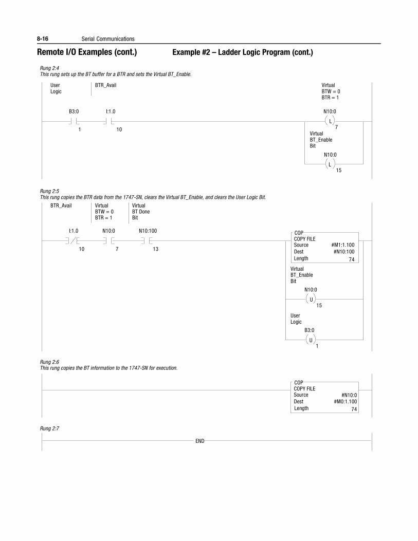
8-16 Serial Communications
Remote I/O Examples (cont.) Example #2 – Ladder Logic Program (cont.)
B3:0
Rung 2:4 This rung sets up the BT buffer for a BTR and sets the Virtual BT_Enable.
1 7
Rung 2:5 This rung copies the BTR data from the 1747-SN, clears the Virtual BT_Enable, and clears the User Logic Bit.
Rung 2:6 This rung copies the BT information to the 1747-SN for execution.
L
10
I:1.0
User Logic
BTR_Avail Virtual BTW = 0 BTR = 1
N10:0
15 L
N10:0
Virtual BT_Enable Bit
I:1.0
10 13 7
N10:0 N10:100
BTR_Avail Virtual BTW = 0 BTR = 1
Virtual BT Done Bit
15 U
N10:0
Virtual BT_Enable Bit
COP COPY FILE Source Dest Length
User Logic
1 U
B3:0
COP COPY FILE Source Dest Length
Rung 2:7
END
#M1:1.100 #N10:100
74
#N10:0 #M0:1.100
74
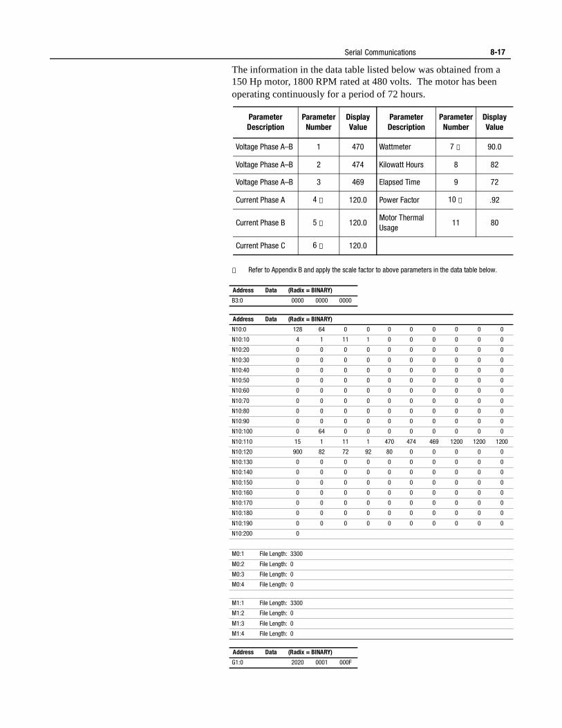
Serial Communications 8-17
The information in the data table listed below was obtained from a 150 Hp motor, 1800 RPM rated at 480 volts. The motor has been operating continuously for a period of 72 hours.
① Refer to Appendix B and apply the scale factor to above parameters in the data table below.
ParameterDescription
ParameterNumber
DisplayValue
ParameterDescription
ParameterNumber
DisplayValue
Voltage Phase A–B 1 470 Wattmeter 7 ① 90.0
Voltage Phase A–B 2 474 Kilowatt Hours 8 82
Voltage Phase A–B 3 469 Elapsed Time 9 72
Current Phase A 4 ① 120.0 Power Factor 10 ① .92
Current Phase B 5 ① 120.0Motor Thermal Usage
11 80
Current Phase C 6 ① 120.0
Address Data (Radix = BINARY)
B3:0 0000 0000 0000
Address Data (Radix = BINARY)
N10:0 128 64 0 0 0 0 0 0 0 0
N10:10 4 1 11 1 0 0 0 0 0 0
N10:20 0 0 0 0 0 0 0 0 0 0
N10:30 0 0 0 0 0 0 0 0 0 0
N10:40 0 0 0 0 0 0 0 0 0 0
N10:50 0 0 0 0 0 0 0 0 0 0
N10:60 0 0 0 0 0 0 0 0 0 0
N10:70 0 0 0 0 0 0 0 0 0 0
N10:80 0 0 0 0 0 0 0 0 0 0
N10:90 0 0 0 0 0 0 0 0 0 0
N10:100 0 64 0 0 0 0 0 0 0 0
N10:110 15 1 11 1 470 474 469 1200 1200 1200
N10:120 900 82 72 92 80 0 0 0 0 0
N10:130 0 0 0 0 0 0 0 0 0 0
N10:140 0 0 0 0 0 0 0 0 0 0
N10:150 0 0 0 0 0 0 0 0 0 0
N10:160 0 0 0 0 0 0 0 0 0 0
N10:170 0 0 0 0 0 0 0 0 0 0
N10:180 0 0 0 0 0 0 0 0 0 0
N10:190 0 0 0 0 0 0 0 0 0 0
N10:200 0
M0:1 File Length: 3300
M0:2 File Length: 0
M0:3 File Length: 0
M0:4 File Length: 0
M1:1 File Length: 3300
M1:2 File Length: 0
M1:3 File Length: 0
M1:4 File Length: 0
Address Data (Radix = BINARY)
G1:0 2020 0001 000F
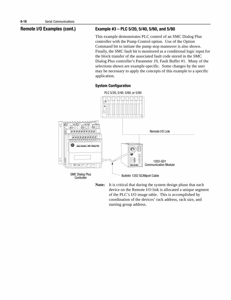
8-18 Serial Communications
Remote I/O Examples (cont.) Example #3 – PLC 5/20, 5/40, 5/60, and 5/80
This example demonstrates PLC control of an SMC Dialog Plus controller with the Pump Control option. Use of the Option Command bit to initiate the pump stop maneuver is also shown. Finally, the SMC fault bit is monitored as a conditional logic input for the block transfer of the associated fault code stored in the SMC Dialog Plus controller’s Parameter 19, Fault Buffer #1. Many of the selections shown are example-specific. Some changes by the user may be necessary to apply the concepts of this example to a specific application.
System Configuration
Note: It is critical that during the system design phase that each device on the Remote I/O link is allocated a unique segment of the PLC’s I/O image table. This is accomplished by coordination of the devices’ rack address, rack size, and starting group address.
Remote I/O Link
SMC Dialog Plus Controller
1203-GD1
Re m I/O
Re m I/O STS
Re m I/O AC T
H ea lth
SC AN bus STS
FA ULT
2
SH
1
V+
V-
L11
L23
L35
11
21
12
22
13
23
14
24
15
25
16
26
17
27
18
28
19
29
20
30
G
Communication Module
Bulletin 1202 SCANport Cable
PLC 5/20, 5/40. 5/60, or 5/80
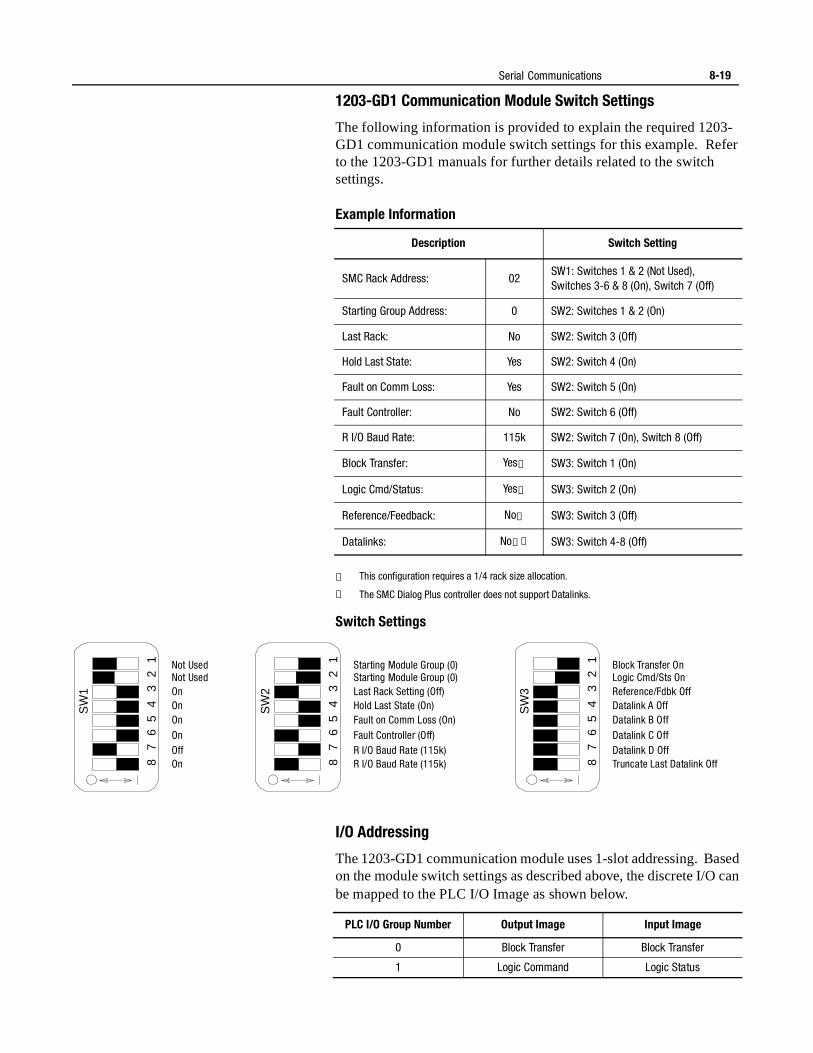
Serial Communications 8-19
1203-GD1 Communication Module Switch Settings
The following information is provided to explain the required 1203-GD1 communication module switch settings for this example. Refer to the 1203-GD1 manuals for further details related to the switch settings.
Example Information
① This configuration requires a 1/4 rack size allocation.
② The SMC Dialog Plus controller does not support Datalinks.
Switch Settings
I/O Addressing
The 1203-GD1 communication module uses 1-slot addressing. Based on the module switch settings as described above, the discrete I/O can be mapped to the PLC I/O Image as shown below.
Description Switch Setting
SMC Rack Address: 02SW1: Switches 1 & 2 (Not Used), Switches 3-6 & 8 (On), Switch 7 (Off)
Starting Group Address: 0 SW2: Switches 1 & 2 (On)
Last Rack: No SW2: Switch 3 (Off)
Hold Last State: Yes SW2: Switch 4 (On)
Fault on Comm Loss: Yes SW2: Switch 5 (On)
Fault Controller: No SW2: Switch 6 (Off)
R I/O Baud Rate: 115k SW2: Switch 7 (On), Switch 8 (Off)
Block Transfer: Yes① SW3: Switch 1 (On)
Logic Cmd/Status: Yes① SW3: Switch 2 (On)
Reference/Feedback: No① SW3: Switch 3 (Off)
Datalinks: No①② SW3: Switch 4-8 (Off)
SW
1
8 7
6 5
4 3
2 1 Not Used
Not Used On On On On Off On
SW
2
8 7
6 5
4 3
2 1 Starting Module Group (0)
Starting Module Group (0) Last Rack Setting (Off) Hold Last State (On) Fault on Comm Loss (On) Fault Controller (Off) R I/O Baud Rate (115k) R I/O Baud Rate (115k)
SW
3
8 7
6 5
4 3
2 1 Block Transfer On
Logic Cmd/Sts On Reference/Fdbk Off Datalink A Off Datalink B Off Datalink C Off Datalink D Off Truncate Last Datalink Off
PLC I/O Group Number Output Image Input Image
0 Block Transfer Block Transfer
1 Logic Command Logic Status
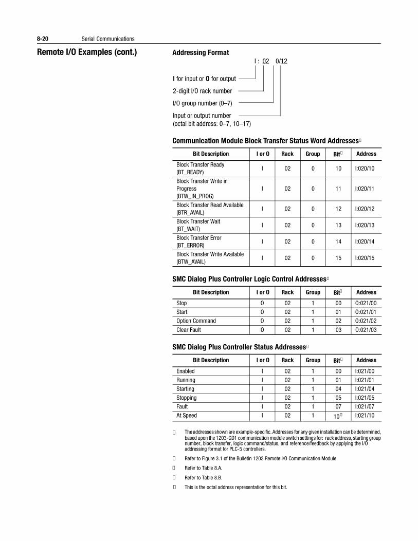
8-20 Serial Communications
Remote I/O Examples (cont.) Addressing Format
Communication Module Block Transfer Status Word Addresses①
SMC Dialog Plus Controller Logic Control Addresses①
SMC Dialog Plus Controller Status Addresses①
① The addresses shown are example-specific. Addresses for any given installation can be determined, based upon the 1203-GD1 communication module switch settings for: rack address, starting group number, block transfer, logic command/status, and reference/feedback by applying the I/O addressing format for PLC-5 controllers.
② Refer to Figure 3.1 of the Bulletin 1203 Remote I/O Communication Module.
③ Refer to Table 8.A.
④ Refer to Table 8.B.
⑤ This is the octal address representation for this bit.
Bit Description I or O Rack Group Bit② Address
Block Transfer Ready(BT_READY)
I 02 0 10 I:020/10
Block Transfer Write in Progress(BTW_IN_PROG)
I 02 0 11 I:020/11
Block Transfer Read Available(BTR_AVAIL)
I 02 0 12 I:020/12
Block Transfer Wait(BT_WAIT)
I 02 0 13 I:020/13
Block Transfer Error(BT_ERROR)
I 02 0 14 I:020/14
Block Transfer Write Available(BTW_AVAIL)
I 02 0 15 I:020/15
Bit Description I or O Rack Group Bit③ Address
Stop O 02 1 00 O:021/00
Start O 02 1 01 O:021/01
Option Command O 02 1 02 O:021/02
Clear Fault O 02 1 03 O:021/03
Bit Description I or O Rack Group Bit④ Address
Enabled I 02 1 00 I:021/00
Running I 02 1 01 I:021/01
Starting I 02 1 04 I:021/04
Stopping I 02 1 05 I:021/05
Fault I 02 1 07 I:021/07
At Speed I 02 1 10⑤ I:021/10
I for input or O for output
2-digit I/O rack number
I/O group number (0–7)
Input or output number(octal bit address: 0–7, 10–17)
I : 02 0/12
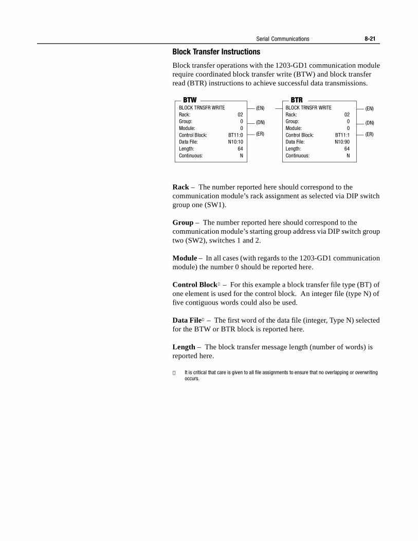
Serial Communications 8-21
Block Transfer Instructions
Block transfer operations with the 1203-GD1 communication module require coordinated block transfer write (BTW) and block transfer read (BTR) instructions to achieve successful data transmissions.
Rack – The number reported here should correspond to the communication module’s rack assignment as selected via DIP switch group one (SW1).
Group – The number reported here should correspond to the communication module’s starting group address via DIP switch group two (SW2), switches 1 and 2.
Module – In all cases (with regards to the 1203-GD1 communication module) the number 0 should be reported here.
Control Block① – For this example a block transfer file type (BT) of one element is used for the control block. An integer file (type N) of five contiguous words could also be used.
Data File① – The first word of the data file (integer, Type N) selected for the BTW or BTR block is reported here.
Length – The block transfer message length (number of words) is reported here.
① It is critical that care is given to all file assignments to ensure that no overlapping or overwriting occurs.
BLOCK TRNSFR WRITERack: 02Group: 0Module: 0Control Block: BT11:0Data File: N10:10Length: 64Continuous: N
BTW(EN)
(DN)
(ER)
BLOCK TRNSFR WRITERack: 02Group: 0Module: 0Control Block: BT11:1Data File: N10:90Length: 64Continuous: N
BTR(EN)
(DN)
(ER)
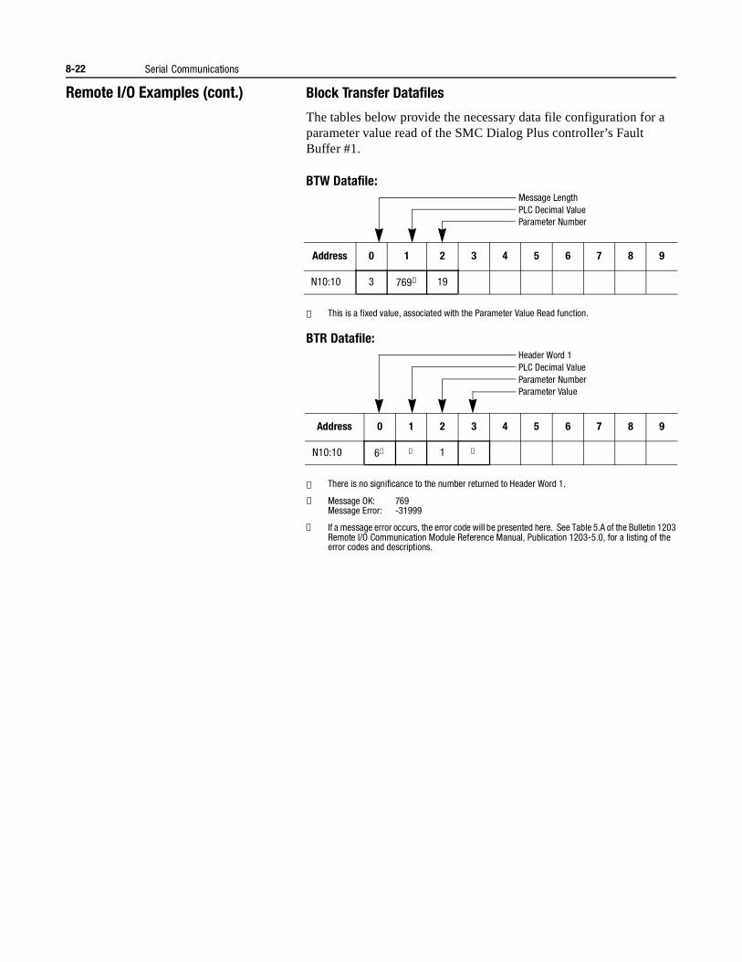
8-22 Serial Communications
Remote I/O Examples (cont.) Block Transfer Datafiles
The tables below provide the necessary data file configuration for a parameter value read of the SMC Dialog Plus controller’s Fault Buffer #1.
BTW Datafile:
① This is a fixed value, associated with the Parameter Value Read function.
BTR Datafile:
① There is no significance to the number returned to Header Word 1.
② Message OK: 769Message Error: -31999
③ If a message error occurs, the error code will be presented here. See Table 5.A of the Bulletin 1203 Remote I/O Communication Module Reference Manual, Publication 1203-5.0, for a listing of the error codes and descriptions.
Address 0 1 2 3 4 5 6 7 8 9
N10:10 3 769① 19
Address 0 1 2 3 4 5 6 7 8 9
N10:10 6① ② 1 ③
Message LengthPLC Decimal ValueParameter Number
Header Word 1PLC Decimal ValueParameter NumberParameter Value
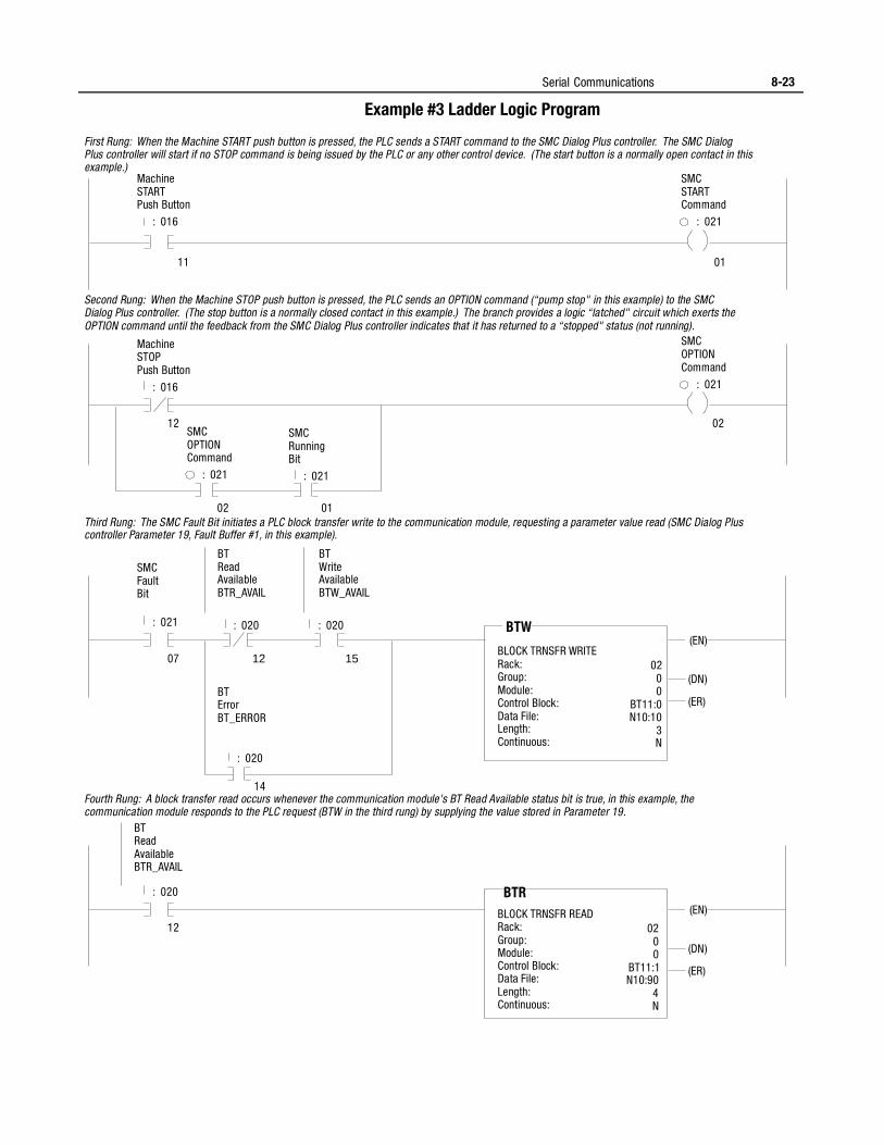
Serial Communications 8-23
Example #3 Ladder Logic Program
Machine START Push Button
: 016
SMC START Command
: 021
11 01
Machine STOP Push Button
: 016
SMC OPTION Command
: 021
First Rung: When the Machine START push button is pressed, the PLC sends a START command to the SMC Dialog Plus controller. The SMC Dialog Plus controller will start if no STOP command is being issued by the PLC or any other control device. (The start button is a normally open contact in this example.)
02 01
02
Second Rung: When the Machine STOP push button is pressed, the PLC sends an OPTION command (“pump stop" in this example) to the SMC Dialog Plus controller. (The stop button is a normally closed contact in this example.) The branch provides a logic “latched" circuit which exerts the OPTION command until the feedback from the SMC Dialog Plus controller indicates that it has returned to a “stopped" status (not running).
SMC OPTION Command
: 021
SMC Running Bit
: 021
12
Third Rung: The SMC Fault Bit initiates a PLC block transfer write to the communication module, requesting a parameter value read (SMC Dialog Plus controller Parameter 19, Fault Buffer #1, in this example).
SMC Fault Bit
: 021
07
BT Read Available BTR_AVAIL
BT Write Available BTW_AVAIL
: 020 : 020
12 15
BT Error BT_ERROR
14
BLOCK TRNSFR WRITE Rack: Group: Module: Control Block: Data File: Length: Continuous:
BTW
02 0 0
BT11:0 N10:10
3 N
(EN)
(DN)
(ER)
Fourth Rung: A block transfer read occurs whenever the communication module's BT Read Available status bit is true, in this example, the communication module responds to the PLC request (BTW in the third rung) by supplying the value stored in Parameter 19.
: 020
12
BT Read Available BTR_AVAIL
BLOCK TRNSFR READ Rack: Group: Module: Control Block: Data File: Length: Continuous:
BTR
02 0 0
BT11:1 N10:90
4 N
(EN)
(DN)
(ER)
: 020
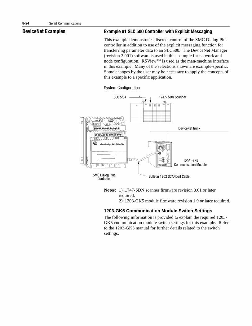
8-24 Serial Communications
DeviceNet Examples Example #1 SLC 500 Controller with Explicit Messaging
This example demonstrates discreet control of the SMC Dialog Plus controller in addition to use of the explicit messaging function for transferring parameter data to an SLC500. The DeviceNet Manager (revision 3.001) software is used in this example for network and node configuration. RSView™ is used as the man-machine interface in this example. Many of the selections shown are example-specific. Some changes by the user may be necessary to apply the concepts of this example to a specific application.
System Configuration
Notes: 1) 1747-SDN scanner firmware revision 3.01 or later required.2) 1203-GK5 module firmware revision 1.9 or later required.
1203-GK5 Communication Module Switch SettingsThe following information is provided to explain the required 1203-GK5 communication module switch settings for this example. Refer to the 1203-GK5 manual for further details related to the switch settings.
SLC 5/02 or higher 1747-SN Scanner
Remote I/O Link
SMC Dialog Plus Controller
1203-GD1
Re m I/O
Re m I/O STS
Re m I/O AC T
H ea lth
SC AN bus STS
FA ULT
2
SH
1
V+
V-
L11
L23
L35
11
21
12
22
13
23
14
24
15
25
16
26
17
27
18
28
19
29
20
30
G
Communication Module
Bulletin 1202 SCANport Cable
4 SDN Scanner
DeviceNet trunk
GK5
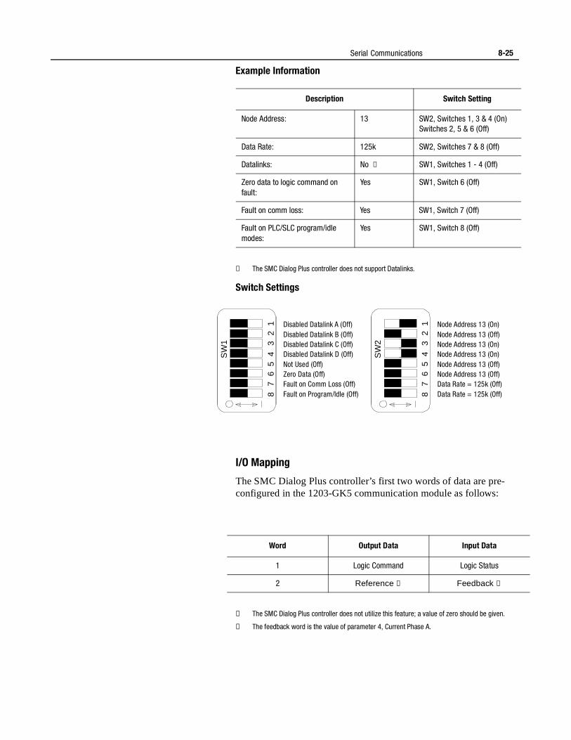
Serial Communications 8-25
Example Information
① The SMC Dialog Plus controller does not support Datalinks.
Switch Settings
I/O Mapping
The SMC Dialog Plus controller’s first two words of data are pre-configured in the 1203-GK5 communication module as follows:
① The SMC Dialog Plus controller does not utilize this feature; a value of zero should be given.
② The feedback word is the value of parameter 4, Current Phase A.
Description Switch Setting
Node Address: 13 SW2, Switches 1, 3 & 4 (On)Switches 2, 5 & 6 (Off)
Data Rate: 125k SW2, Switches 7 & 8 (Off)
Datalinks: No ① SW1, Switches 1 - 4 (Off)
Zero data to logic command on fault:
Yes SW1, Switch 6 (Off)
Fault on comm loss: Yes SW1, Switch 7 (Off)
Fault on PLC/SLC program/idle modes:
Yes SW1, Switch 8 (Off)
Disabled Datalink A (Off)Disabled Datalink B (Off)Disabled Datalink C (Off)Disabled Datalink D (Off)Not Used (Off)Zero Data (Off)Fault on Comm Loss (Off)Fault on Program/Idle (Off)
SW
1
SW
2
8 8
7 7
6 6
5 5
4 4
3 3
2 2
1 1 Node Address 13 (On)Node Address 13 (Off)Node Address 13 (On)Node Address 13 (On)Node Address 13 (Off)Node Address 13 (Off)Data Rate = 125k (Off)Data Rate = 125k (Off)
Word Output Data Input Data
1 Logic Command Logic Status
2 Reference ① Feedback ②
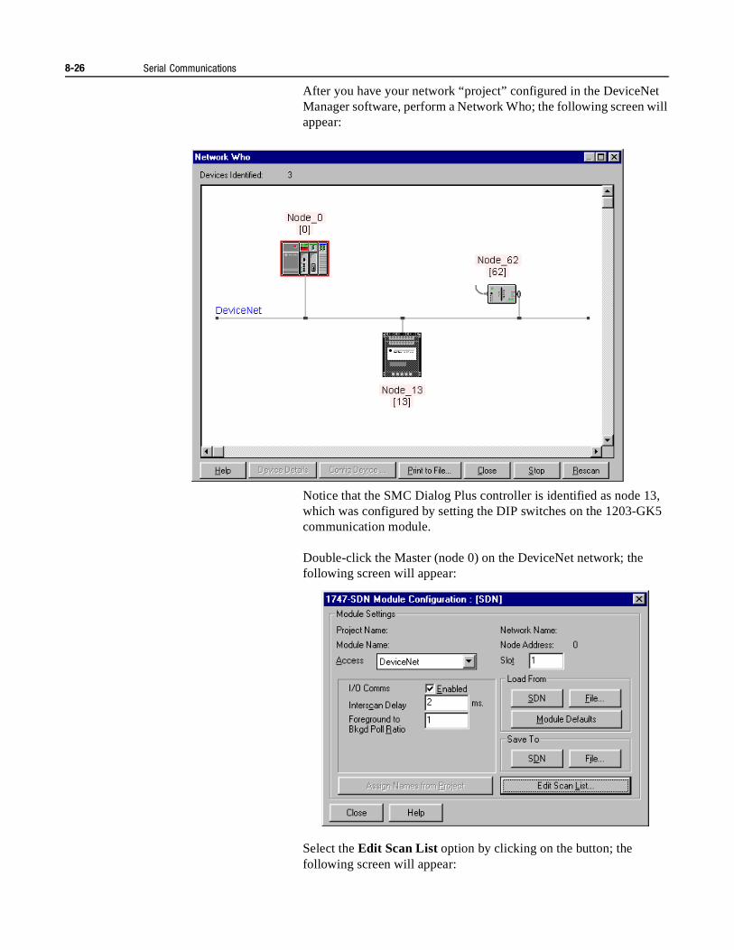
8-26 Serial Communications
After you have your network “project” configured in the DeviceNet Manager software, perform a Network Who; the following screen will appear:
Notice that the SMC Dialog Plus controller is identified as node 13, which was configured by setting the DIP switches on the 1203-GK5 communication module.
Double-click the Master (node 0) on the DeviceNet network; the following screen will appear:
Select the Edit Scan List option by clicking on the button; the following screen will appear:
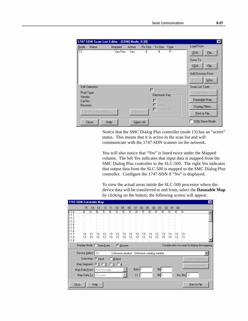
Serial Communications 8-27
Notice that the SMC Dialog Plus controller (node 13) has an “active” status. This means that it is active in the scan list and will communicate with the 1747-SDN scanner on the network.
You will also notice that “Yes” is listed twice under the Mapped column. The left Yes indicates that input data is mapped from the SMC Dialog Plus controller to the SLC-500. The right Yes indicates that output data from the SLC-500 is mapped to the SMC Dialog Plus controller. Configure the 1747-SDN if “No” is displayed.
To view the actual areas inside the SLC-500 processor where the device data will be transferred to and from, select the Datatable Map by clicking on the button; the following screen will appear:
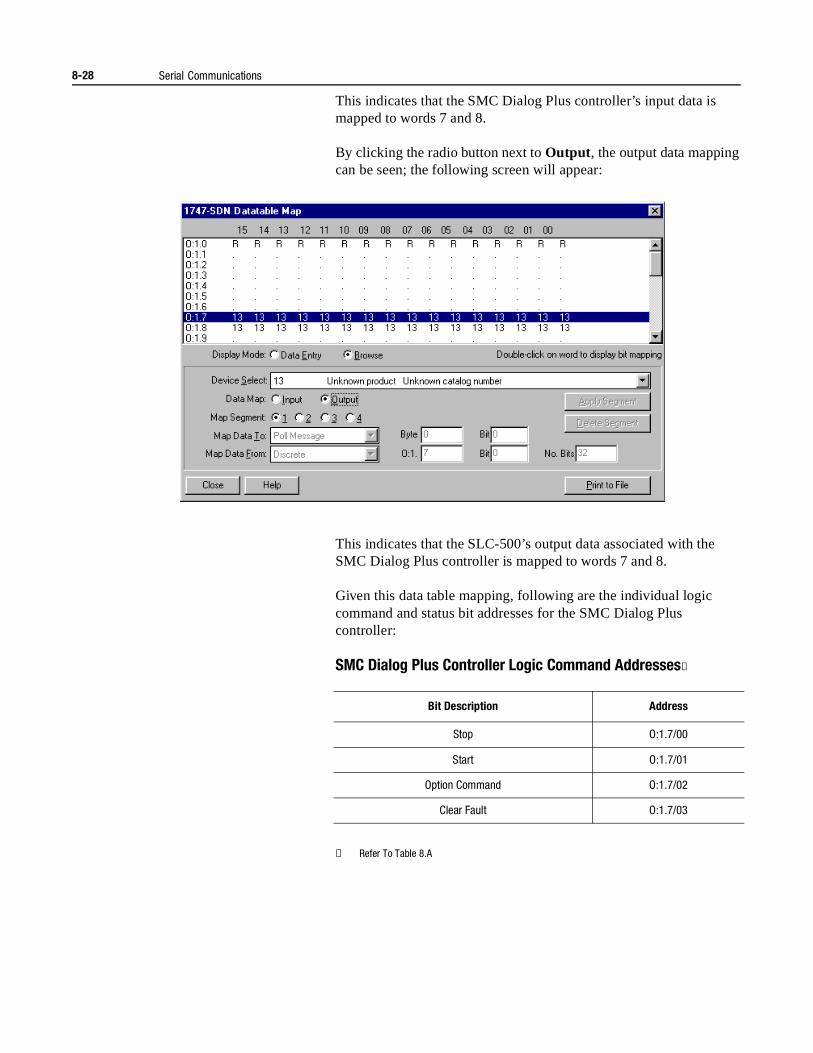
8-28 Serial Communications
This indicates that the SMC Dialog Plus controller’s input data is mapped to words 7 and 8.
By clicking the radio button next to Output , the output data mapping can be seen; the following screen will appear:
This indicates that the SLC-500’s output data associated with the SMC Dialog Plus controller is mapped to words 7 and 8.
Given this data table mapping, following are the individual logic command and status bit addresses for the SMC Dialog Plus controller:
SMC Dialog Plus Controller Logic Command Addresses①
① Refer To Table 8.A
Bit Description Address
Stop O:1.7/00
Start O:1.7/01
Option Command O:1.7/02
Clear Fault O:1.7/03
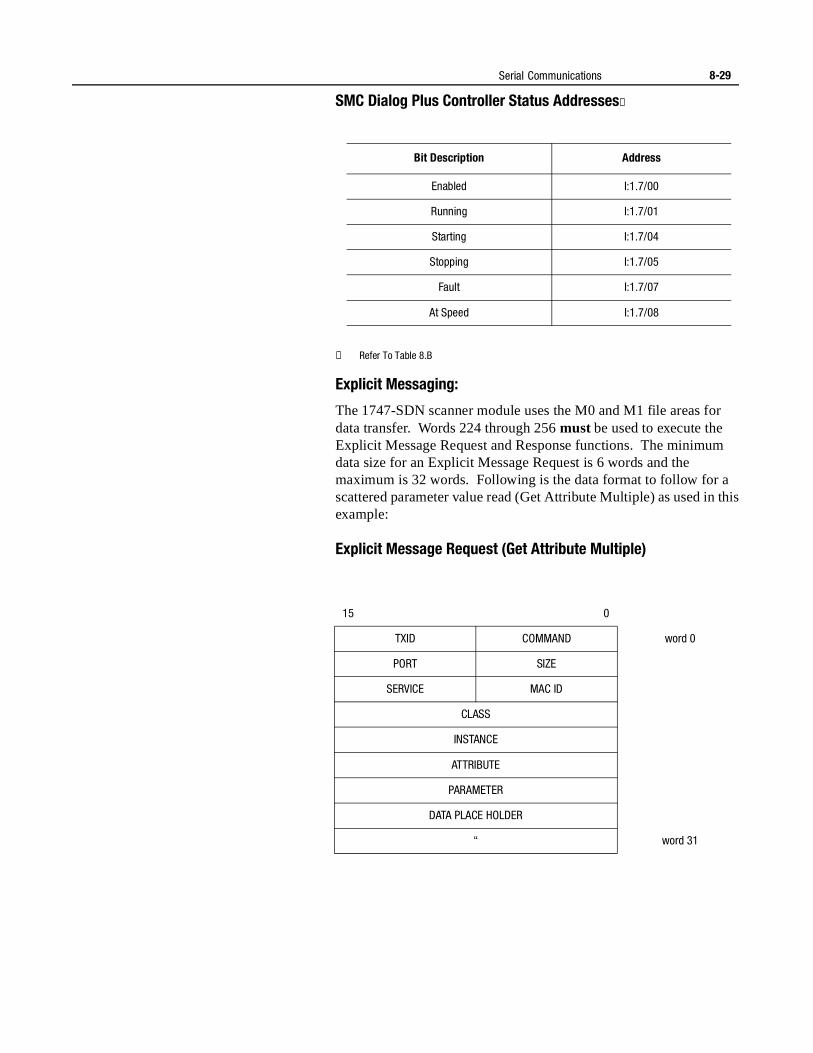
Serial Communications 8-29
SMC Dialog Plus Controller Status Addresses②
② Refer To Table 8.B
Explicit Messaging:
The 1747-SDN scanner module uses the M0 and M1 file areas for data transfer. Words 224 through 256 must be used to execute the Explicit Message Request and Response functions. The minimum data size for an Explicit Message Request is 6 words and the maximum is 32 words. Following is the data format to follow for a scattered parameter value read (Get Attribute Multiple) as used in this example:
Explicit Message Request (Get Attribute Multiple)
Bit Description Address
Enabled I:1.7/00
Running I:1.7/01
Starting I:1.7/04
Stopping I:1.7/05
Fault I:1.7/07
At Speed I:1.7/08
15 0
TXID COMMAND word 0
PORT SIZE
SERVICE MAC ID
CLASS
INSTANCE
ATTRIBUTE
PARAMETER
DATA PLACE HOLDER
“ word 31
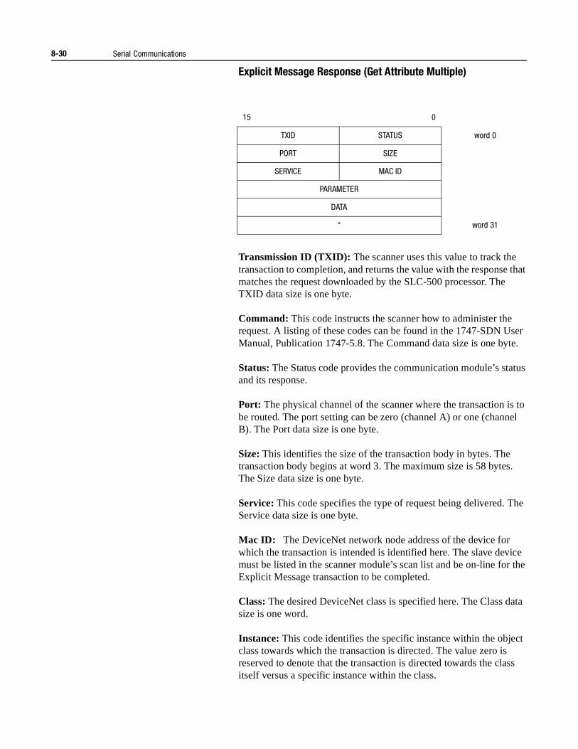
8-30 Serial Communications
Explicit Message Response (Get Attribute Multiple)
Transmission ID (TXID): The scanner uses this value to track the transaction to completion, and returns the value with the response that matches the request downloaded by the SLC-500 processor. The TXID data size is one byte.
Command: This code instructs the scanner how to administer the request. A listing of these codes can be found in the 1747-SDN User Manual, Publication 1747-5.8. The Command data size is one byte.
Status: The Status code provides the communication module’s status and its response.
Port: The physical channel of the scanner where the transaction is to be routed. The port setting can be zero (channel A) or one (channel B). The Port data size is one byte.
Size: This identifies the size of the transaction body in bytes. The transaction body begins at word 3. The maximum size is 58 bytes. The Size data size is one byte.
Service: This code specifies the type of request being delivered. The Service data size is one byte.
Mac ID: The DeviceNet network node address of the device for which the transaction is intended is identified here. The slave device must be listed in the scanner module’s scan list and be on-line for the Explicit Message transaction to be completed.
Class: The desired DeviceNet class is specified here. The Class data size is one word.
Instance: This code identifies the specific instance within the object class towards which the transaction is directed. The value zero is reserved to denote that the transaction is directed towards the class itself versus a specific instance within the class.
15 0
TXID STATUS word 0
PORT SIZE
SERVICE MAC ID
PARAMETER
DATA
“ word 31
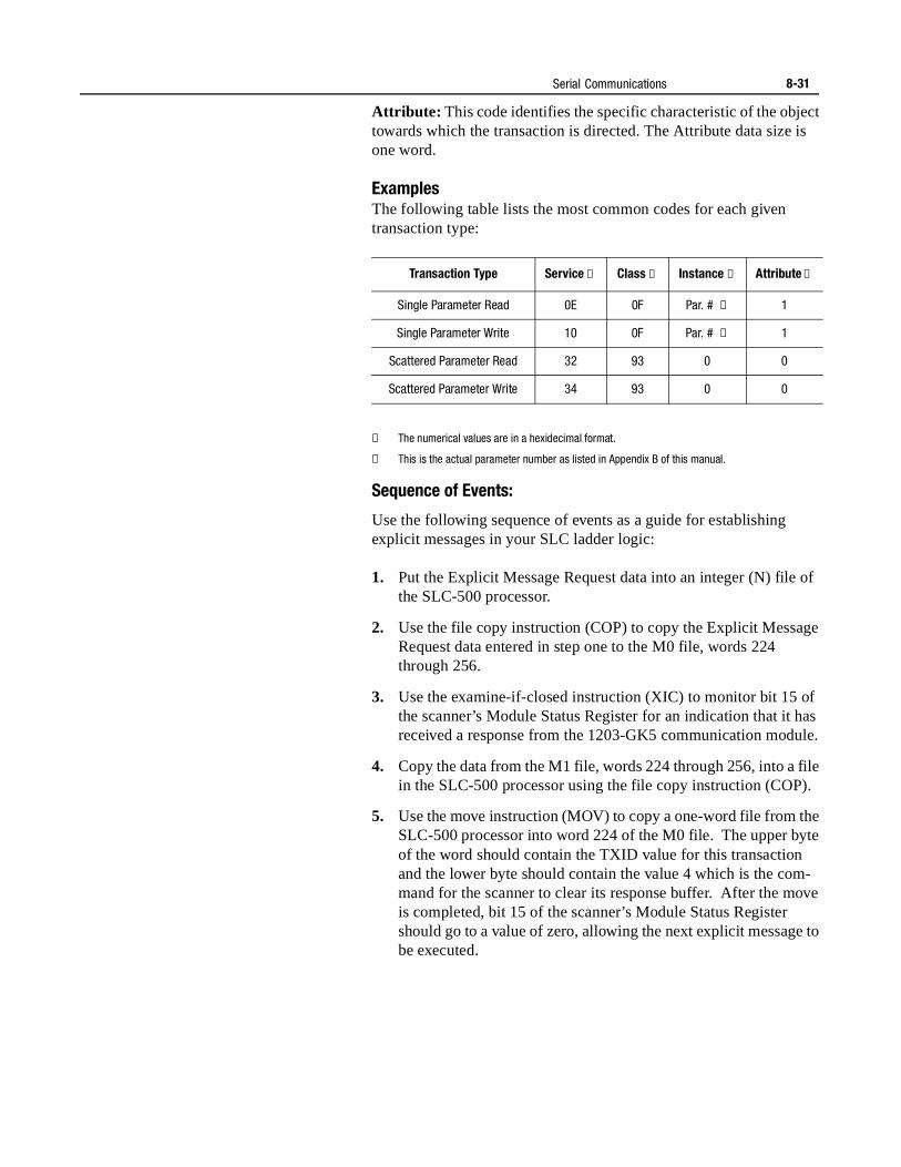
Serial Communications 8-31
Attribute: This code identifies the specific characteristic of the object towards which the transaction is directed. The Attribute data size is one word.
ExamplesThe following table lists the most common codes for each given transaction type:
① The numerical values are in a hexidecimal format.
② This is the actual parameter number as listed in Appendix B of this manual.
Sequence of Events:
Use the following sequence of events as a guide for establishing explicit messages in your SLC ladder logic:
1. Put the Explicit Message Request data into an integer (N) file of the SLC-500 processor.
2. Use the file copy instruction (COP) to copy the Explicit Message Request data entered in step one to the M0 file, words 224 through 256.
3. Use the examine-if-closed instruction (XIC) to monitor bit 15 of the scanner’s Module Status Register for an indication that it has received a response from the 1203-GK5 communication module.
4. Copy the data from the M1 file, words 224 through 256, into a file in the SLC-500 processor using the file copy instruction (COP).
5. Use the move instruction (MOV) to copy a one-word file from the SLC-500 processor into word 224 of the M0 file. The upper byte of the word should contain the TXID value for this transaction and the lower byte should contain the value 4 which is the com-mand for the scanner to clear its response buffer. After the move is completed, bit 15 of the scanner’s Module Status Register should go to a value of zero, allowing the next explicit message to be executed.
Transaction Type Service ① Class ① Instance ① Attribute ①
Single Parameter Read 0E 0F Par. # ② 1
Single Parameter Write 10 0F Par. # ② 1
Scattered Parameter Read 32 93 0 0
Scattered Parameter Write 34 93 0 0
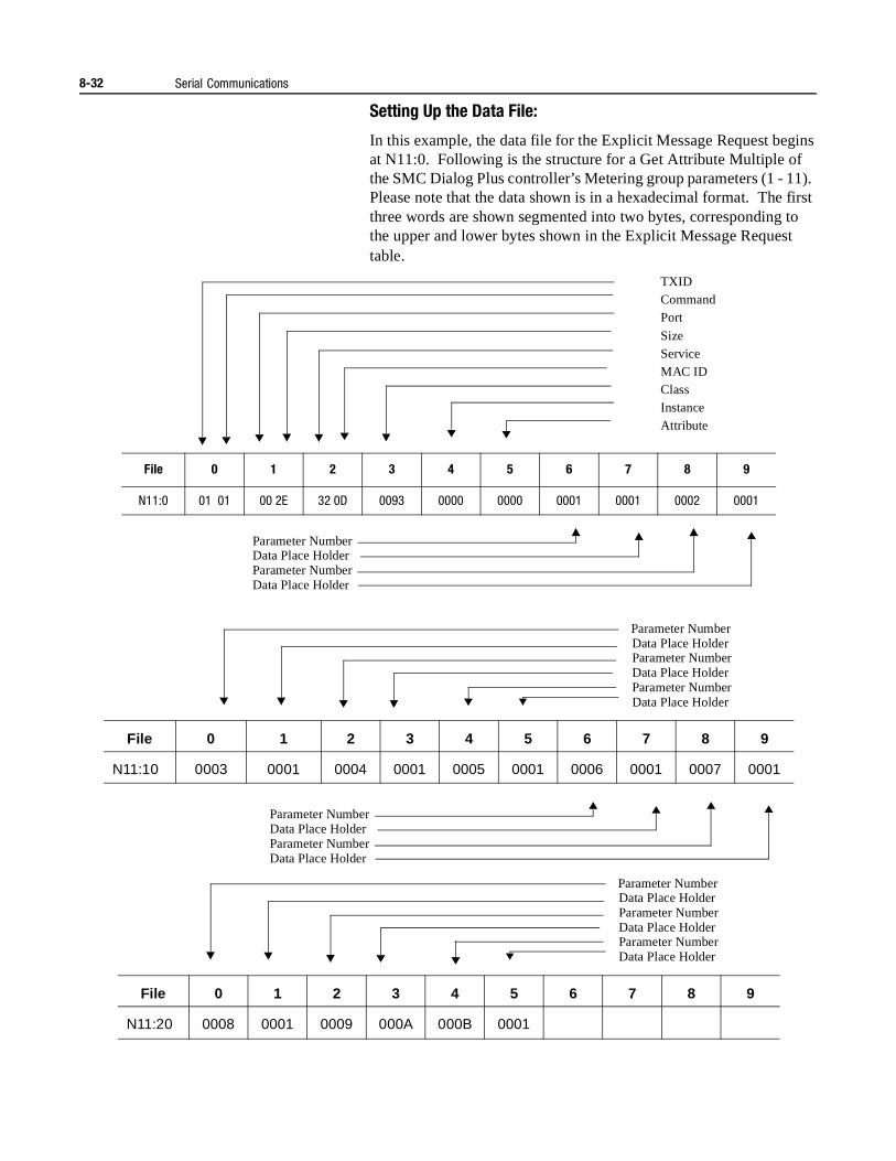
8-32 Serial Communications
Setting Up the Data File:
In this example, the data file for the Explicit Message Request begins at N11:0. Following is the structure for a Get Attribute Multiple of the SMC Dialog Plus controller’s Metering group parameters (1 - 11). Please note that the data shown is in a hexadecimal format. The first three words are shown segmented into two bytes, corresponding to the upper and lower bytes shown in the Explicit Message Request table.
File 0 1 2 3 4 5 6 7 8 9
N11:0 01 01 00 2E 32 0D 0093 0000 0000 0001 0001 0002 0001
TXIDCommandPort
SizeServiceMAC IDClassInstanceAttribute
Parameter NumberData Place HolderParameter NumberData Place Holder
Parameter NumberData Place HolderParameter NumberData Place HolderParameter NumberData Place Holder
File 0 1 2 3 4 5 6 7 8 9
N11:10 0003 0001 0004 0001 0005 0001 0006 0001 0007 0001
File 0 1 2 3 4 5 6 7 8 9
N11:20 0008 0001 0009 000A 000B 0001
Parameter NumberData Place HolderParameter NumberData Place Holder
Parameter NumberData Place HolderParameter NumberData Place HolderParameter NumberData Place Holder
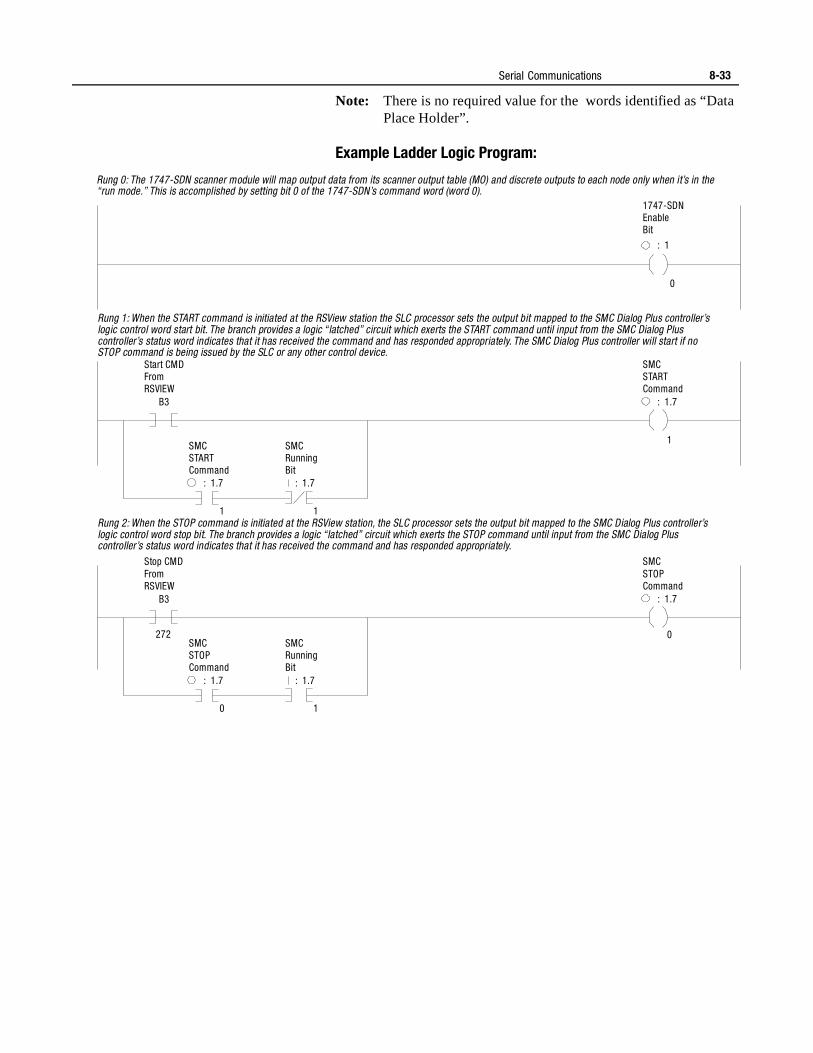
Serial Communications 8-33
Note: There is no required value for the words identified as “Data Place Holder”.
Example Ladder Logic Program:
Rung 0: The 1747-SDN scanner module will map output data from its scanner output table (MO) and discrete outputs to each node only when it’s in the “run mode.” This is accomplished by setting bit 0 of the 1747-SDN’s command word (word 0).
Rung 1: When the START command is initiated at the RSView station the SLC processor sets the output bit mapped to the SMC Dialog Plus controller’s logic control word start bit. The branch provides a logic “latched” circuit which exerts the START command until input from the SMC Dialog Plus controller’s status word indicates that it has received the command and has responded appropriately. The SMC Dialog Plus controller will start if no STOP command is being issued by the SLC or any other control device.
Rung 2: When the STOP command is initiated at the RSView station, the SLC processor sets the output bit mapped to the SMC Dialog Plus controller’slogic control word stop bit. The branch provides a logic “latched” circuit which exerts the STOP command until input from the SMC Dialog Plus controller’s status word indicates that it has received the command and has responded appropriately.
1747-SDNEnableBit
SMCSTARTCommand
SMCSTOPCommand
SMCSTARTCommand
SMCSTOPCommand
SMCRunningBit
SMCRunningBit
Start CMDFromRSVIEW
Stop CMDFromRSVIEW
: 1
: 1.7
: 1.7
0
1
0
: 1.7
: 1.7
1
0
1
1
: 1.7
: 1.7
B3
B3
272
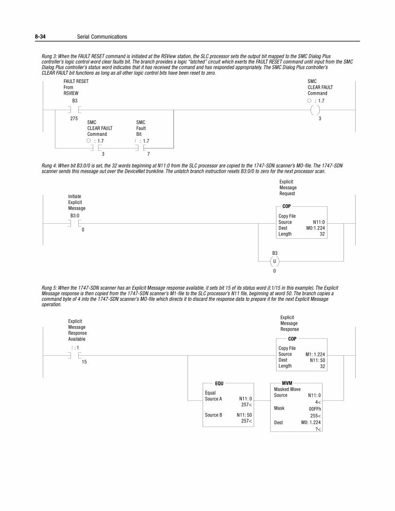
8-34 Serial Communications
Rung 3: When the FAULT RESET command is initiated at the RSView station, the SLC processor sets the output bit mapped to the SMC Dialog Plus controller’s logic control word clear faults bit. The branch provides a logic “latched” circuit which exerts the FAULT RESET command until input from the SMCDialog Plus controller’s status word indicates that it has received the comand and has responded appropriately. The SMC Dialog Plus controller’s CLEAR FAULT bit functions as long as all other logic control bits have been reset to zero.
Rung 4: When bit B3:0/0 is set, the 32 words beginning at N11:0 from the SLC processor are copied to the 1747-SDN scanner’s MO-file. The 1747-SDNscanner sends this message out over the DeviceNet trunkline. The unlatch branch instruction resets B3:0/0 to zero for the next processor scan.
SMCCLEAR FAULTCommand
SMCCLEAR FAULTCommand
SMCFaultBit
FAULT RESETFromRSVIEW
InitiateExplicitMessage
ExplicitMessageRequest
Copy FileSourceDestLength
N11:0M0:1.224
32
: 1.7
: 1.7 : 1.7
B3
B3:0
B3
COP
275
0
0
U
3 7
3
Rung 5: When the 1747-SDN scanner has an Explicit Message response available, it sets bit 15 of its status word (I:1/15 in this example). The ExplicitMessage response is then copied from the 1747-SDN scanner’s M1-file to the SLC processor’s N11 file, beginning at word 50. The branch copies a command byte of 4 into the 1747-SDN scanner’s MO-file which directs it to discard the response data to prepare it for the next Explicit Message operation.
ExplicitMessageResponseAvailable
ExplicitMessageResponse
Copy FileSourceDestLength
Masked MoveSourceEqual
Source A
MaskSource B
Dest
M1: 1.224N11: 50
32
N11: 04<
00FFh255<
M0: 1.224?<
N11: 0257<
N11: 50257<
: 1
COP
MVMEQU
15
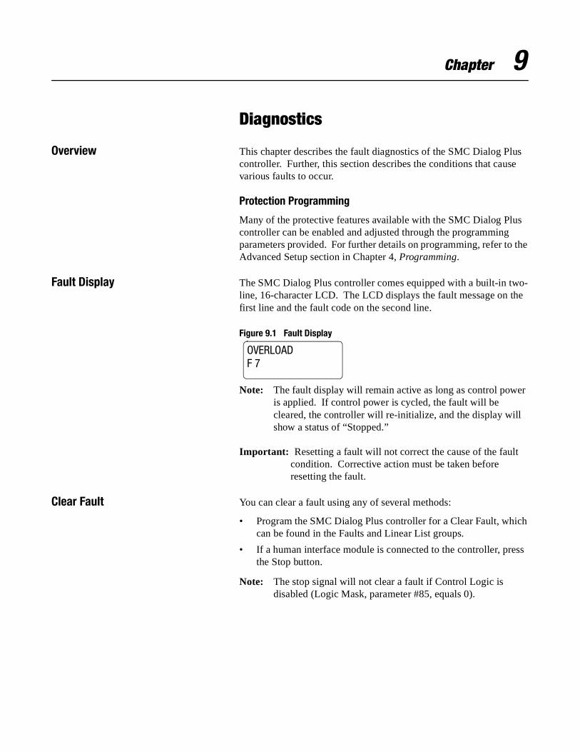
Chapter 9
Diagnostics
Overview This chapter describes the fault diagnostics of the SMC Dialog Plus controller. Further, this section describes the conditions that cause various faults to occur.
Protection Programming
Many of the protective features available with the SMC Dialog Plus controller can be enabled and adjusted through the programming parameters provided. For further details on programming, refer to the Advanced Setup section in Chapter 4, Programming.
Fault Display The SMC Dialog Plus controller comes equipped with a built-in two-line, 16-character LCD. The LCD displays the fault message on the first line and the fault code on the second line.
Figure 9.1 Fault Display
Note: The fault display will remain active as long as control power is applied. If control power is cycled, the fault will be cleared, the controller will re-initialize, and the display will show a status of “Stopped.”
Important: Resetting a fault will not correct the cause of the fault condition. Corrective action must be taken before resetting the fault.
Clear Fault You can clear a fault using any of several methods:
• Program the SMC Dialog Plus controller for a Clear Fault, which can be found in the Faults and Linear List groups.
• If a human interface module is connected to the controller, press the Stop button.
Note: The stop signal will not clear a fault if Control Logic is disabled (Logic Mask, parameter #85, equals 0).
OVERLOADF 7
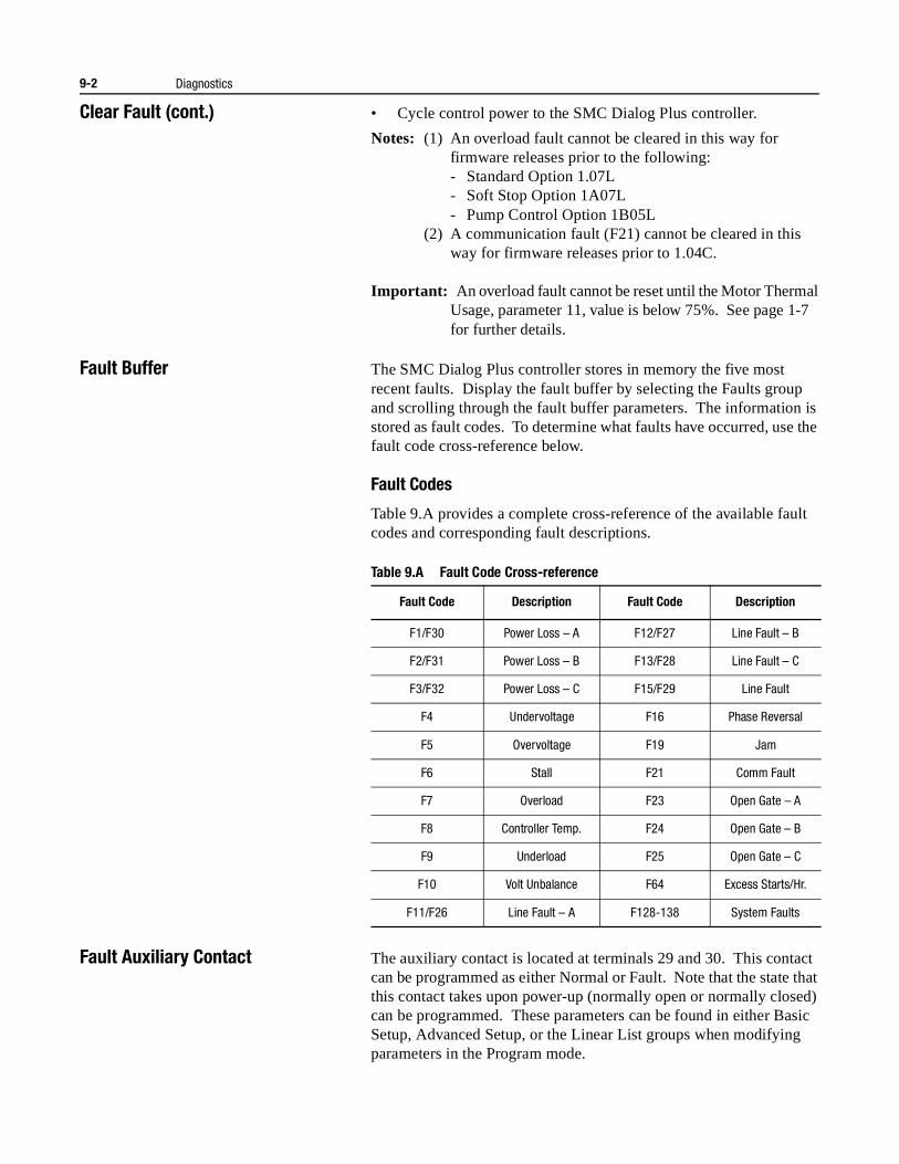
9-2 Diagnostics
Clear Fault (cont.) • Cycle control power to the SMC Dialog Plus controller.
Notes: (1) An overload fault cannot be cleared in this way for firmware releases prior to the following:- Standard Option 1.07L- Soft Stop Option 1A07L- Pump Control Option 1B05L
(2) A communication fault (F21) cannot be cleared in thisway for firmware releases prior to 1.04C.
Important: An overload fault cannot be reset until the Motor Thermal Usage, parameter 11, value is below 75%. See page 1-7 for further details.
Fault Buffer The SMC Dialog Plus controller stores in memory the five most recent faults. Display the fault buffer by selecting the Faults group and scrolling through the fault buffer parameters. The information is stored as fault codes. To determine what faults have occurred, use the fault code cross-reference below.
Fault Codes
Table 9.A provides a complete cross-reference of the available fault codes and corresponding fault descriptions.
Table 9.A Fault Code Cross-reference
Fault Auxiliary Contact The auxiliary contact is located at terminals 29 and 30. This contact can be programmed as either Normal or Fault. Note that the state that this contact takes upon power-up (normally open or normally closed) can be programmed. These parameters can be found in either Basic Setup, Advanced Setup, or the Linear List groups when modifying parameters in the Program mode.
Fault Code Description Fault Code Description
F1/F30 Power Loss – A F12/F27 Line Fault – B
F2/F31 Power Loss – B F13/F28 Line Fault – C
F3/F32 Power Loss – C F15/F29 Line Fault
F4 Undervoltage F16 Phase Reversal
F5 Overvoltage F19 Jam
F6 Stall F21 Comm Fault
F7 Overload F23 Open Gate – A
F8 Controller Temp. F24 Open Gate – B
F9 Underload F25 Open Gate – C
F10 Volt Unbalance F64 Excess Starts/Hr.
F11/F26 Line Fault – A F128-138 System Faults
Diagnostics 9-3
Fault Definitions Power Loss
Power loss indicates that an input power phase is not present. The controller’s LCD display will identify the missing phase.
Note: If all three phases are absent when a start command is issued, the LCD will display “Starting” without motor rotation.
Line Fault ①
Line fault with the affected phase displayed identifies three possible pre-start conditions.
• Phase loss
• Load loss
• Shorted SCR
Line fault with no phase indication is displayed when one of the following conditions occurs while the SMC Dialog Plus controller is in the run mode.
• Phase loss
• Load loss
• Shorted SCR
Phase Reversal
Phase reversal is indicated when the incoming power to the SMC Dialog Plus controller is in any sequence other than ABC. This pre-start protective feature can be disabled.
Overvoltage and Undervoltage Protection ①
Overvoltage and undervoltage protection are user-defined as a percentage of the programmed line voltage. The SMC Dialog Plus controller continuously monitors the three supply phases. The calculated average is then compared to the programmed trip level.
① Phase loss, overvoltage, and undervoltage protection are disabled during braking operation.
9-4 Diagnostics
Fault Definitions(cont.)
Voltage Unbalance ①
Voltage unbalance is detected by monitoring the three phase supply voltages. The formula used to calculate the percentage voltage unbalance is as follows:
Vu = 100 (Vd / Va)
Vu: Percent voltage unbalance
Vd: Maximum voltage deviation from the average voltage
Va: Average voltage
The controller will shut down when the calculated voltage unbalance reaches the user-programmed trip percentages.
Stall Protection
Stall protection is enabled at the end of the programmed ramp time after a motor has been started. If the controller senses that the motor is not up-to-speed at the end of ramp, it will shut down after the user-selected delay time has elapsed.
Jam Detection ②
Jam detection operates when the SMC Dialog Plus controller status is “at speed.” The controller will shut down when the motor current reaches the user-defined trip level, which is based on a percentage of the programmed motor full load current rating.
Overload Protection
Overload protection is enabled in the Calibration group by programming the:
• Overload class
• Overload reset
• Motor FLC
• Service factor
Refer to Chapter 5 for more information on calibration.
Underload ②
Underload protection is available for undercurrent monitoring. The controller will shut down when the motor current drops below the trip level. This trip level, a percentage of the motor’s full load current rating, can be programmed.
① Voltage unbalance protection is disabled during braking operation.
② Jam detection and underload protection are disabled during slow speed and braking operation.
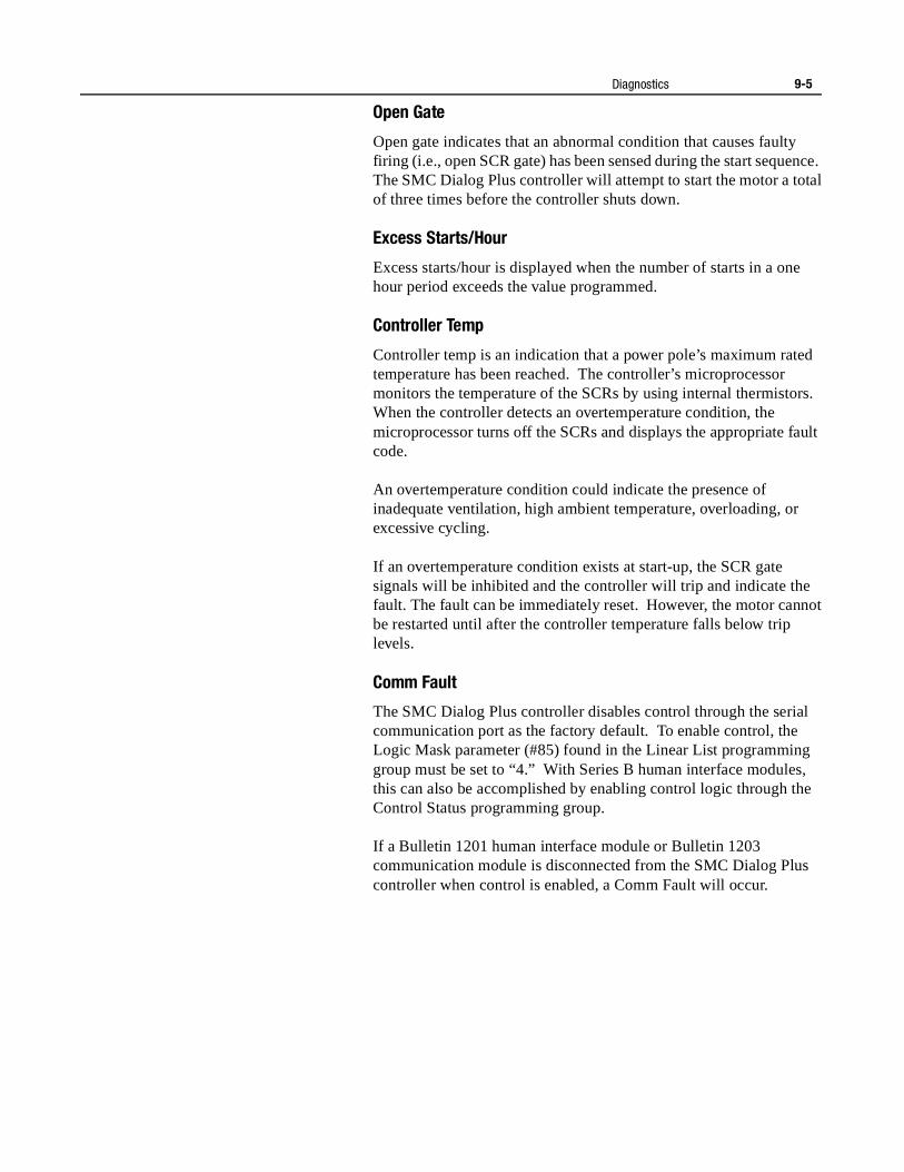
Diagnostics 9-5
Open Gate
Open gate indicates that an abnormal condition that causes faulty firing (i.e., open SCR gate) has been sensed during the start sequence. The SMC Dialog Plus controller will attempt to start the motor a total of three times before the controller shuts down.
Excess Starts/Hour
Excess starts/hour is displayed when the number of starts in a one hour period exceeds the value programmed.
Controller Temp
Controller temp is an indication that a power pole’s maximum rated temperature has been reached. The controller’s microprocessor monitors the temperature of the SCRs by using internal thermistors. When the controller detects an overtemperature condition, the microprocessor turns off the SCRs and displays the appropriate fault code.
An overtemperature condition could indicate the presence of inadequate ventilation, high ambient temperature, overloading, or excessive cycling.
If an overtemperature condition exists at start-up, the SCR gate signals will be inhibited and the controller will trip and indicate the fault. The fault can be immediately reset. However, the motor cannot be restarted until after the controller temperature falls below trip levels.
Comm Fault
The SMC Dialog Plus controller disables control through the serial communication port as the factory default. To enable control, the Logic Mask parameter (#85) found in the Linear List programming group must be set to “4.” With Series B human interface modules, this can also be accomplished by enabling control logic through the Control Status programming group.
If a Bulletin 1201 human interface module or Bulletin 1203 communication module is disconnected from the SMC Dialog Plus controller when control is enabled, a Comm Fault will occur.

9-6 Diagnostics
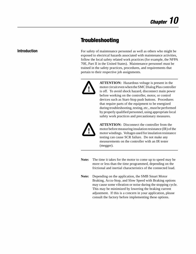
Chapter 10
Troubleshooting
Introduction For safety of maintenance personnel as well as others who might be exposed to electrical hazards associated with maintenance activities, follow the local safety related work practices (for example, the NFPA 70E, Part II in the United States). Maintenance personnel must be trained in the safety practices, procedures, and requirements that pertain to their respective job assignments.
Note: The time it takes for the motor to come up to speed may be more or less than the time programmed, depending on the frictional and inertial characteristics of the connected load.
Note: Depending on the application, the SMB Smart Motor Braking, Accu-Stop, and Slow Speed with Braking options may cause some vibration or noise during the stopping cycle. This may be minimized by lowering the braking current adjustment. If this is a concern in your application, please consult the factory before implementing these options.
!ATTENTION: Hazardous voltage is present in the motor circuit even when the SMC Dialog Plus controller is off. To avoid shock hazard, disconnect main power before working on the controller, motor, or control devices such as Start-Stop push buttons. Procedures that require parts of the equipment to be energized during troubleshooting, testing, etc., must be performed by properly qualified personnel, using appropriate local safety work practices and precautionary measures.
!ATTENTION: Disconnect the controller from the motor before measuring insulation resistance (IR) of the motor windings. Voltages used for insulation resistance testing can cause SCR failure. Do not make any measurements on the controller with an IR tester (megger).
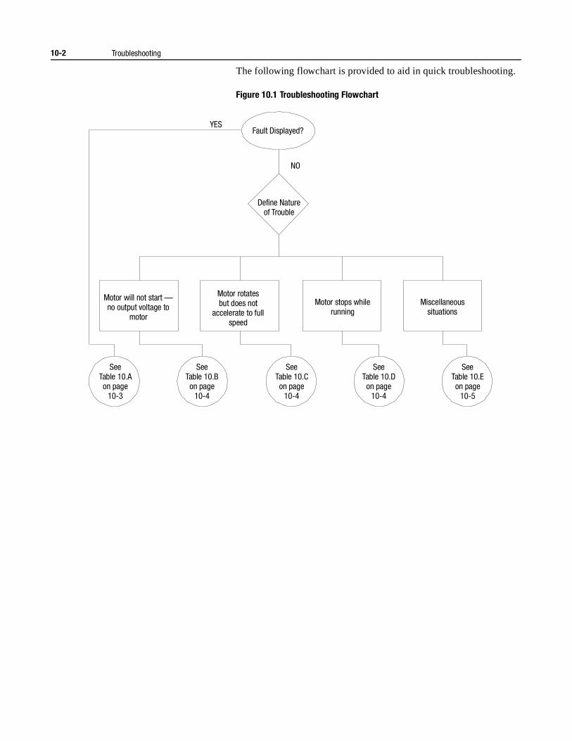
10-2 Troubleshooting
The following flowchart is provided to aid in quick troubleshooting.
Figure 10.1 Troubleshooting Flowchart
SeeTable 10.Aon page
10-3
SeeTable 10.Bon page
10-4
SeeTable 10.Con page
10-4
SeeTable 10.Don page
10-4
SeeTable 10.Eon page
10-5
YES
NO
Fault Displayed?
Define Natureof Trouble
Motor will not start — no output voltage to
motor
Motor rotatesbut does not
accelerate to fullspeed
Motor stops whilerunning
Miscellaneoussituations
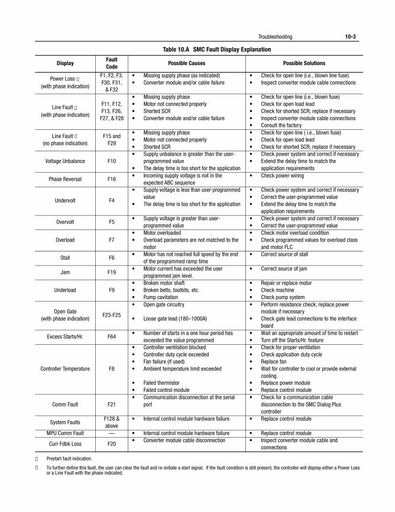
Troubleshooting 10-3
Table 10.A SMC Fault Display Explanation
① Prestart fault indication.
② To further define this fault, the user can clear the fault and re-initiate a start signal. If the fault condition is still present, the controller will display either a Power Loss or a Line Fault with the phase indicated.
DisplayFaultCode
Possible Causes Possible Solutions
Power Loss ①(with phase indication)
F1, F2, F3, F30, F31,
& F32
• Missing supply phase (as indicated)• Converter module and/or cable failure
• Check for open line (i.e., blown line fuse)• Inspect converter module cable connections
Line Fault ①(with phase indication)
F11, F12, F13, F26,
F27, & F28
• Missing supply phase• Motor not connected properly• Shorted SCR• Converter module and/or cable failure
• Check for open line (i.e., blown fuse)• Check for open load lead• Check for shorted SCR; replace if necessary• Inspect converter module cable connections• Consult the factory
Line Fault ②(no phase indication)
F15 and F29
• Missing supply phase• Motor not connected properly• Shorted SCR
• Check for open line ( i.e., blown fuse)• Check for open load lead• Check for shorted SCR; replace if necessary
Voltage Unbalance F10• Supply unbalance is greater than the user-
programmed value• The delay time is too short for the application
• Check power system and correct if necessary• Extend the delay time to match the
application requirements
Phase Reversal F16• Incoming supply voltage is not in the
expected ABC sequence• Check power wiring
Undervolt F4
• Supply voltage is less than user-programmed value
• The delay time is too short for the application
• Check power system and correct if necessary• Correct the user-programmed value• Extend the delay time to match the
application requirements
Overvolt F5• Supply voltage is greater than user-
programmed value• Check power system and correct if necessary• Correct the user-programmed value
Overload F7• Motor overloaded• Overload parameters are not matched to the
motor
• Check motor overload condition• Check programmed values for overload class
and motor FLC
Stall F6• Motor has not reached full speed by the end
of the programmed ramp time• Correct source of stall
Jam F19• Motor current has exceeded the user
programmed jam level.• Correct source of jam
Underload F9• Broken motor shaft• Broken belts, toolbits, etc.• Pump cavitation
• Repair or replace motor• Check machine• Check pump system
Open Gate(with phase indication)
F23-F25
• Open gate circuitry
• Loose gate lead (180–1000A)
• Perform resistance check; replace power module if necessary
• Check gate lead connections to the interface board
Excess Starts/Hr. F64• Number of starts in a one hour period has
exceeded the value programmed• Wait an appropriate amount of time to restart• Turn off the Starts/Hr. feature
Controller Temperature F8
• Controller ventilation blocked• Controller duty cycle exceeded• Fan failure (if used)• Ambient temperature limit exceeded
• Failed thermistor• Failed control module
• Check for proper ventilation• Check application duty cycle• Replace fan• Wait for controller to cool or provide external
cooling• Replace power module• Replace control module
Comm Fault F21• Communication disconnection at the serial
port• Check for a communication cable
disconnection to the SMC Dialog Plus controller
System FaultsF128 &above
• Internal control module hardware failure • Replace control module
MPU Comm Fault — • Internal control module hardware failure • Replace control module
Curr Fdbk Loss F20• Converter module cable disconnection • Inspect converter module cable and
connections
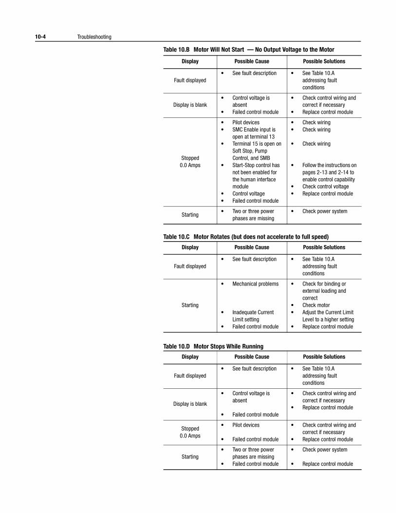
10-4 Troubleshooting
Table 10.B Motor Will Not Start — No Output Voltage to the Motor
Table 10.C Motor Rotates (but does not accelerate to full speed)
Table 10.D Motor Stops While Running
Display Possible Cause Possible Solutions
Fault displayed• See fault description • See Table 10.A
addressing fault conditions
Display is blank• Control voltage is
absent• Failed control module
• Check control wiring and correct if necessary
• Replace control module
Stopped0.0 Amps
• Pilot devices• SMC Enable input is
open at terminal 13• Terminal 15 is open on
Soft Stop, Pump Control, and SMB
• Start-Stop control has not been enabled for the human interface module
• Control voltage• Failed control module
• Check wiring• Check wiring
• Check wiring
• Follow the instructions on pages 2-13 and 2-14 to enable control capability
• Check control voltage• Replace control module
Starting• Two or three power
phases are missing• Check power system
Display Possible Cause Possible Solutions
Fault displayed• See fault description • See Table 10.A
addressing fault conditions
Starting
• Mechanical problems
• Inadequate Current Limit setting
• Failed control module
• Check for binding or external loading and correct
• Check motor• Adjust the Current Limit
Level to a higher setting• Replace control module
Display Possible Cause Possible Solutions
Fault displayed• See fault description • See Table 10.A
addressing fault conditions
Display is blank
• Control voltage is absent
• Failed control module
• Check control wiring and correct if necessary
• Replace control module
Stopped0.0 Amps
• Pilot devices
• Failed control module
• Check control wiring and correct if necessary
• Replace control module
Starting• Two or three power
phases are missing• Failed control module
• Check power system
• Replace control module
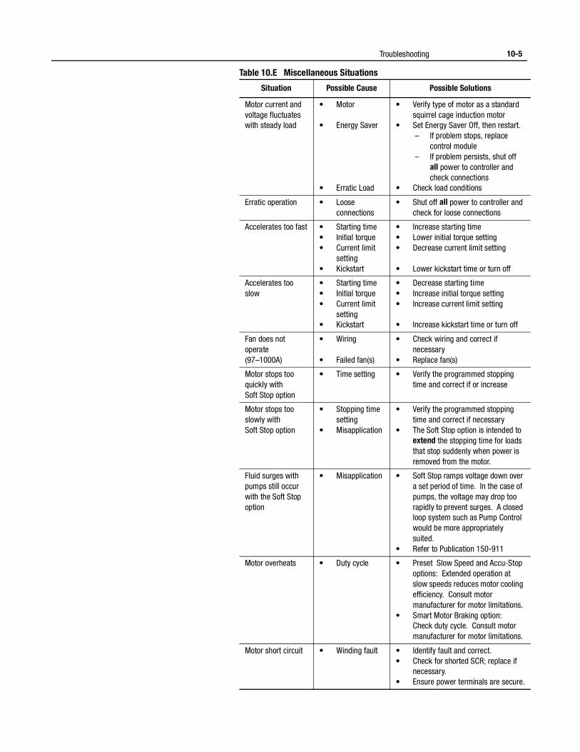
Troubleshooting 10-5
Table 10.E Miscellaneous Situations
Situation Possible Cause Possible Solutions
Motor current and voltage fluctuates with steady load
• Motor
• Energy Saver
• Erratic Load
• Verify type of motor as a standard squirrel cage induction motor
• Set Energy Saver Off, then restart. – If problem stops, replace
control module – If problem persists, shut off
all power to controller and check connections
• Check load conditions
Erratic operation • Loose connections
• Shut off all power to controller and check for loose connections
Accelerates too fast • Starting time• Initial torque• Current limit
setting• Kickstart
• Increase starting time• Lower initial torque setting• Decrease current limit setting
• Lower kickstart time or turn off
Accelerates too slow
• Starting time• Initial torque• Current limit
setting• Kickstart
• Decrease starting time• Increase initial torque setting• Increase current limit setting
• Increase kickstart time or turn off
Fan does not operate(97–1000A)
• Wiring
• Failed fan(s)
• Check wiring and correct if necessary
• Replace fan(s)
Motor stops too quickly with Soft Stop option
• Time setting • Verify the programmed stopping time and correct if or increase
Motor stops too slowly withSoft Stop option
• Stopping time setting
• Misapplication
• Verify the programmed stopping time and correct if necessary
• The Soft Stop option is intended to extend the stopping time for loads that stop suddenly when power is removed from the motor.
Fluid surges with pumps still occur with the Soft Stop option
• Misapplication • Soft Stop ramps voltage down over a set period of time. In the case of pumps, the voltage may drop too rapidly to prevent surges. A closed loop system such as Pump Control would be more appropriately suited.
• Refer to Publication 150-911
Motor overheats • Duty cycle • Preset Slow Speed and Accu-Stop options: Extended operation at slow speeds reduces motor cooling efficiency. Consult motor manufacturer for motor limitations.
• Smart Motor Braking option:Check duty cycle. Consult motor manufacturer for motor limitations.
Motor short circuit • Winding fault • Identify fault and correct.• Check for shorted SCR; replace if
necessary.• Ensure power terminals are secure.
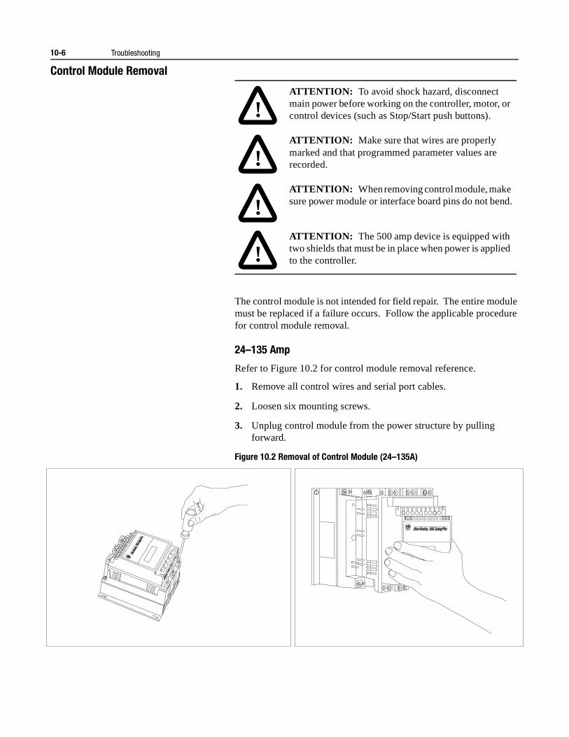
10-6 Troubleshooting
Control Module Removal
The control module is not intended for field repair. The entire module must be replaced if a failure occurs. Follow the applicable procedure for control module removal.
24–135 Amp
Refer to Figure 10.2 for control module removal reference.
1. Remove all control wires and serial port cables.
2. Loosen six mounting screws.
3. Unplug control module from the power structure by pulling forward.
Figure 10.2 Removal of Control Module (24–135A)
!ATTENTION: To avoid shock hazard, disconnect main power before working on the controller, motor, or control devices (such as Stop/Start push buttons).
!ATTENTION: Make sure that wires are properly marked and that programmed parameter values are recorded.
!ATTENTION: When removing control module, make sure power module or interface board pins do not bend.
!ATTENTION: The 500 amp device is equipped with two shields that must be in place when power is applied to the controller.
Troubleshooting 10-7
180–360 Amp
Refer to Figure 10.3 for control module reference.
1. Remove controller access door and serial port cable.
2. Remove controller cover.
3. Remove all control wires and loosen six control module mounting screws.
4. Unplug control module from the interface board by pulling for-ward.
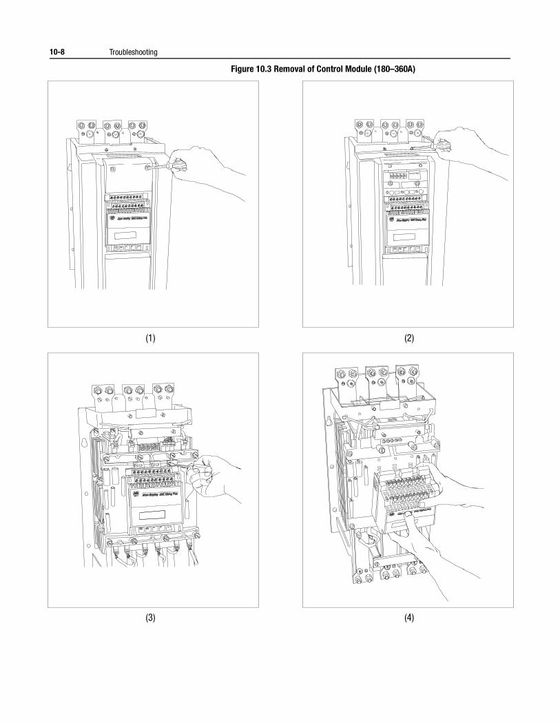
10-8 Troubleshooting
Figure 10.3 Removal of Control Module (180–360A)
(1)
(3)
(2)
(4)
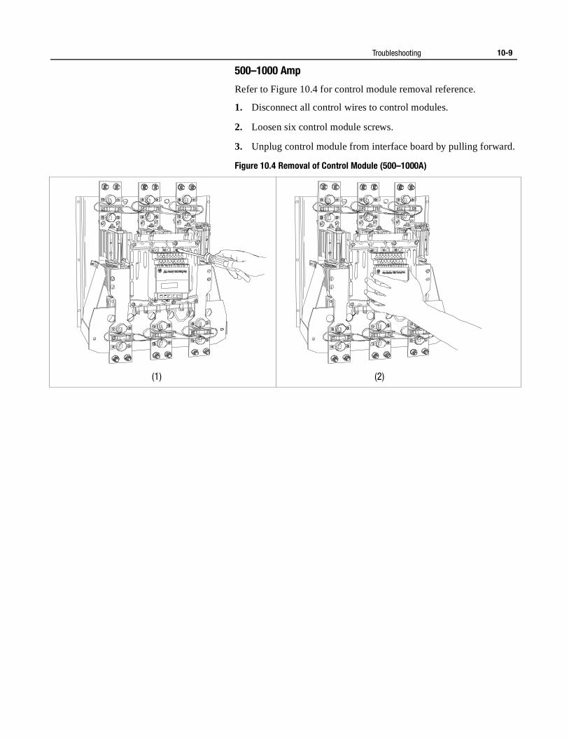
Troubleshooting 10-9
500–1000 Amp
Refer to Figure 10.4 for control module removal reference.
1. Disconnect all control wires to control modules.
2. Loosen six control module screws.
3. Unplug control module from interface board by pulling forward.
Figure 10.4 Removal of Control Module (500–1000A)
(1) (2)
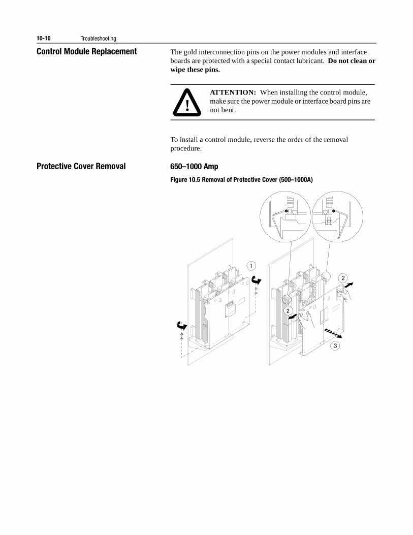
10-10 Troubleshooting
Control Module Replacement The gold interconnection pins on the power modules and interface boards are protected with a special contact lubricant. Do not clean or wipe these pins.
To install a control module, reverse the order of the removal procedure.
Protective Cover Removal 650–1000 Amp
Figure 10.5 Removal of Protective Cover (500–1000A)
!ATTENTION: When installing the control module, make sure the power module or interface board pins are not bent.
1
2
3
2
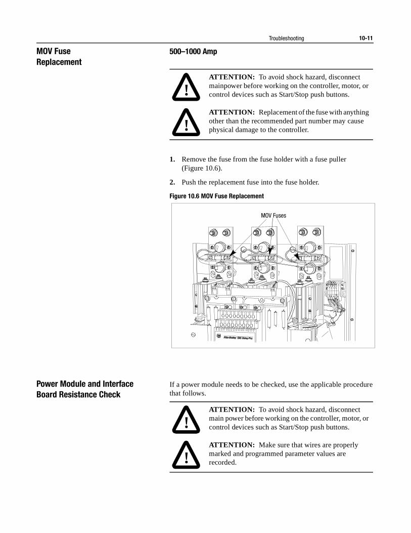
Troubleshooting 10-11
MOV FuseReplacement
500–1000 Amp
1. Remove the fuse from the fuse holder with a fuse puller (Figure 10.6).
2. Push the replacement fuse into the fuse holder.
Figure 10.6 MOV Fuse Replacement
Power Module and Interface Board Resistance Check
If a power module needs to be checked, use the applicable procedure that follows.
!ATTENTION: To avoid shock hazard, disconnect mainpower before working on the controller, motor, or control devices such as Start/Stop push buttons.
!ATTENTION: Replacement of the fuse with anything other than the recommended part number may cause physical damage to the controller.
MOV Fuses
!ATTENTION: To avoid shock hazard, disconnect main power before working on the controller, motor, or control devices such as Start/Stop push buttons.
!ATTENTION: Make sure that wires are properly marked and programmed parameter values are recorded.
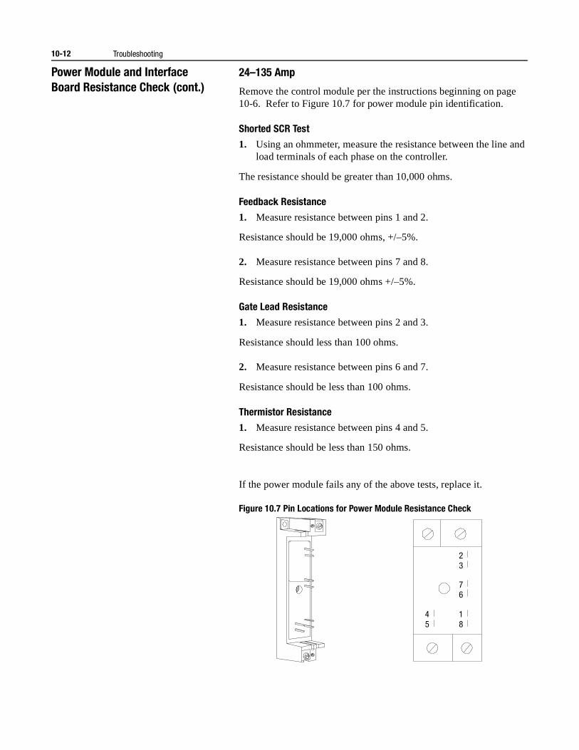
10-12 Troubleshooting
Power Module and Interface Board Resistance Check (cont.)
24–135 Amp
Remove the control module per the instructions beginning on page 10-6. Refer to Figure 10.7 for power module pin identification.
Shorted SCR Test
1. Using an ohmmeter, measure the resistance between the line and load terminals of each phase on the controller.
The resistance should be greater than 10,000 ohms.
Feedback Resistance
1. Measure resistance between pins 1 and 2.
Resistance should be 19,000 ohms, +/–5%.
2. Measure resistance between pins 7 and 8.
Resistance should be 19,000 ohms +/–5%.
Gate Lead Resistance
1. Measure resistance between pins 2 and 3.
Resistance should less than 100 ohms.
2. Measure resistance between pins 6 and 7.
Resistance should be less than 100 ohms.
Thermistor Resistance
1. Measure resistance between pins 4 and 5.
Resistance should be less than 150 ohms.
If the power module fails any of the above tests, replace it.
Figure 10.7 Pin Locations for Power Module Resistance Check
2 3
7 6
1 8
4 5
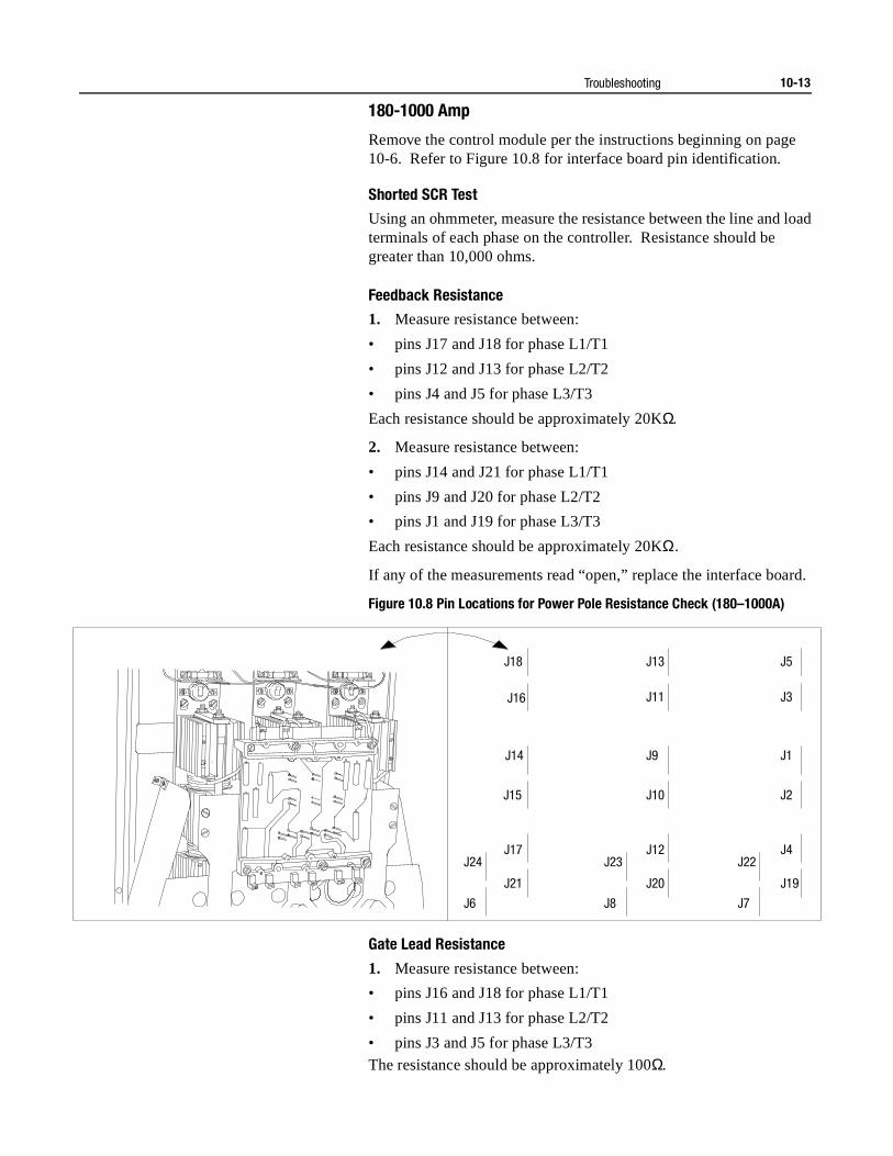
Troubleshooting 10-13
180-1000 Amp
Remove the control module per the instructions beginning on page 10-6. Refer to Figure 10.8 for interface board pin identification.
Shorted SCR Test
Using an ohmmeter, measure the resistance between the line and load terminals of each phase on the controller. Resistance should be greater than 10,000 ohms.
Feedback Resistance
1. Measure resistance between:
• pins J17 and J18 for phase L1/T1
• pins J12 and J13 for phase L2/T2
• pins J4 and J5 for phase L3/T3
Each resistance should be approximately 20KΩ.
2. Measure resistance between:
• pins J14 and J21 for phase L1/T1
• pins J9 and J20 for phase L2/T2
• pins J1 and J19 for phase L3/T3
Each resistance should be approximately 20KΩ.
If any of the measurements read “open,” replace the interface board.
Figure 10.8 Pin Locations for Power Pole Resistance Check (180–1000A)
Gate Lead Resistance
1. Measure resistance between:
• pins J16 and J18 for phase L1/T1
• pins J11 and J13 for phase L2/T2
• pins J3 and J5 for phase L3/T3
The resistance should be approximately 100Ω.
J18
J16
J14
J15
J17 J12 J4 J24 J23 J22
J21 J20 J19
J6 J8 J7
J3
J5 J13
J11
J2 J10
J1 J9
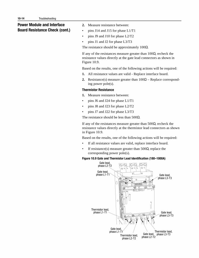
10-14 Troubleshooting
Power Module and Interface Board Resistance Check (cont.)
2. Measure resistance between:
• pins J14 and J15 for phase L1/T1
• pins J9 and J10 for phase L2/T2
• pins J1 and J2 for phase L3/T3
The resistance should be approximately 100Ω.
If any of the resistances measure greater than 100Ω, recheck the resistance values directly at the gate lead connectors as shown in Figure 10.9.
Based on the results, one of the following actions will be required:
1. All resistance values are valid - Replace interface board.
2. Resistance(s) measure greater than 100Ω – Replace correspond-ing power pole(s).
Thermistor Resistance
1. Measure resistance between:
• pins J6 and J24 for phase L1/T1
• pins J8 and J23 for phase L2/T2
• pins J7 and J22 for phase L3/T3
The resistance should be less than 500Ω.
If any of the resistances measure greater than 500Ω, recheck the resistance values directly at the thermistor lead connectors as shown in Figure 10.9.
Based on the results, one of the following actions will be required:
• If all resistance values are valid, replace interface board.
• If resistance(s) measure greater than 500Ω, replace the corresponding power pole(s).
Figure 10.9 Gate and Thermistor Lead Identification (180–1000A)Gate lead,
phase L2-T2
Gate lead, phase L1-T1 Gate lead,
phase L3-T3
Gate lead, phase L3-T3
Gate lead, phase L2-T2
Gate lead, phase L1-T1
Thermistor lead, phase L1-T1
Thermistor lead, phase L3-T3 Thermistor lead,
phase L2-T2
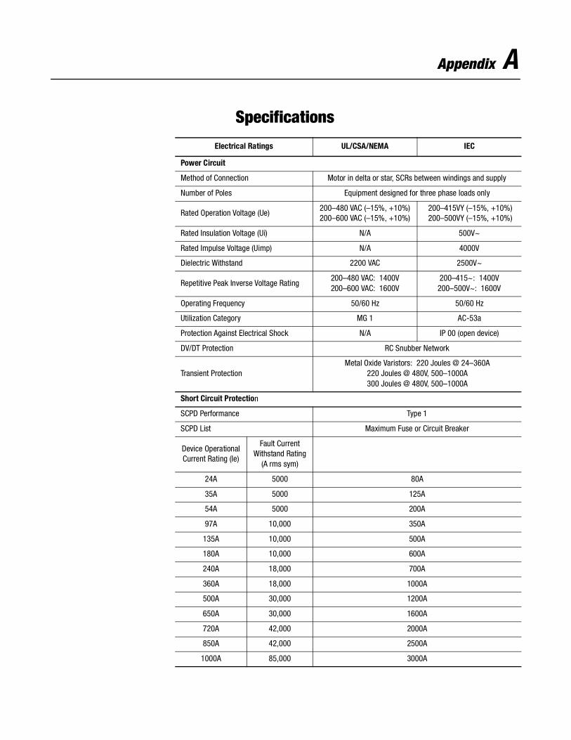
Appendix A
Specifications
Electrical Ratings UL/CSA/NEMA IEC
Power Circuit
Method of Connection Motor in delta or star, SCRs between windings and supply
Number of Poles Equipment designed for three phase loads only
Rated Operation Voltage (Ue)200–480 VAC (–15%, +10%)200–600 VAC (–15%, +10%)
200–415VY (–15%, +10%)200–500VY (–15%, +10%)
Rated Insulation Voltage (Ui) N/A 500V~
Rated Impulse Voltage (Uimp) N/A 4000V
Dielectric Withstand 2200 VAC 2500V~
Repetitive Peak Inverse Voltage Rating200–480 VAC: 1400V200–600 VAC: 1600V
200–415~: 1400V200–500V~: 1600V
Operating Frequency 50/60 Hz 50/60 Hz
Utilization Category MG 1 AC-53a
Protection Against Electrical Shock N/A IP 00 (open device)
DV/DT Protection RC Snubber Network
Transient ProtectionMetal Oxide Varistors: 220 Joules @ 24–360A
220 Joules @ 480V, 500–1000A300 Joules @ 480V, 500–1000A
Short Circuit Protection
SCPD Performance Type 1
SCPD List Maximum Fuse or Circuit Breaker
Device OperationalCurrent Rating (Ie)
Fault CurrentWithstand Rating
(A rms sym)
24A 5000 80A
35A 5000 125A
54A 5000 200A
97A 10,000 350A
135A 10,000 500A
180A 10,000 600A
240A 18,000 700A
360A 18,000 1000A
500A 30,000 1200A
650A 30,000 1600A
720A 42,000 2000A
850A 42,000 2500A
1000A 85,000 3000A
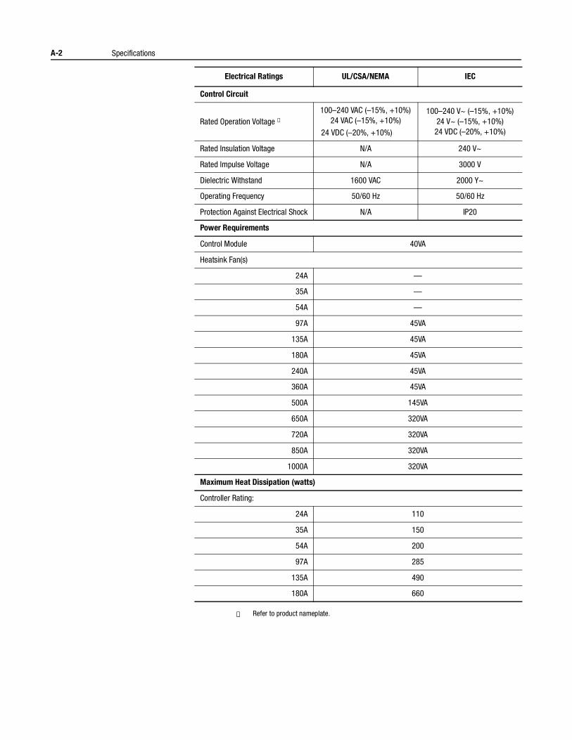
A-2 Specifications
① Refer to product nameplate.
Electrical Ratings UL/CSA/NEMA IEC
Control Circuit
Rated Operation Voltage ①100–240 VAC (–15%, +10%)
24 VAC (–15%, +10%)
24 VDC (–20%, +10%)
100–240 V~ (–15%, +10%)24 V~ (–15%, +10%)
24 VDC (–20%, +10%)
Rated Insulation Voltage N/A 240 V~
Rated Impulse Voltage N/A 3000 V
Dielectric Withstand 1600 VAC 2000 Y~
Operating Frequency 50/60 Hz 50/60 Hz
Protection Against Electrical Shock N/A IP20
Power Requirements
Control Module 40VA
Heatsink Fan(s)
24A —
35A —
54A —
97A 45VA
135A 45VA
180A 45VA
240A 45VA
360A 45VA
500A 145VA
650A 320VA
720A 320VA
850A 320VA
1000A 320VA
Maximum Heat Dissipation (watts)
Controller Rating:
24A 110
35A 150
54A 200
97A 285
135A 490
180A 660
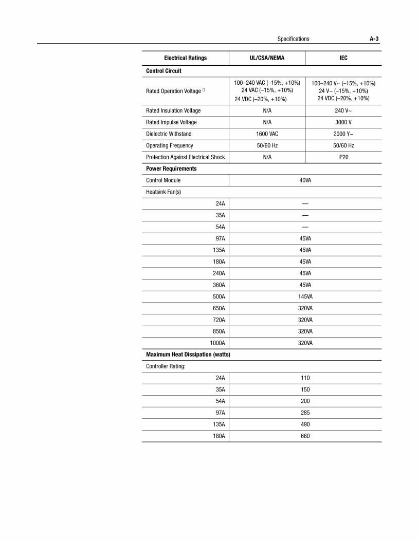
Specifications A-3
Electrical Ratings UL/CSA/NEMA IEC
Control Circuit
Rated Operation Voltage ①100–240 VAC (–15%, +10%)
24 VAC (–15%, +10%)
24 VDC (–20%, +10%)
100–240 V~ (–15%, +10%)24 V~ (–15%, +10%)
24 VDC (–20%, +10%)
Rated Insulation Voltage N/A 240 V~
Rated Impulse Voltage N/A 3000 V
Dielectric Withstand 1600 VAC 2000 Y~
Operating Frequency 50/60 Hz 50/60 Hz
Protection Against Electrical Shock N/A IP20
Power Requirements
Control Module 40VA
Heatsink Fan(s)
24A —
35A —
54A —
97A 45VA
135A 45VA
180A 45VA
240A 45VA
360A 45VA
500A 145VA
650A 320VA
720A 320VA
850A 320VA
1000A 320VA
Maximum Heat Dissipation (watts)
Controller Rating:
24A 110
35A 150
54A 200
97A 285
135A 490
180A 660
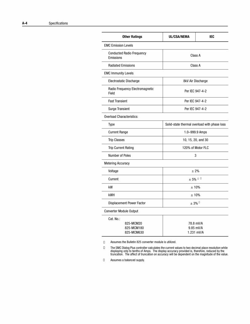
A-4 Specifications
① Assumes the Bulletin 825 converter module is utilized.
② The SMC Dialog Plus controller calculates the current values to two decimal place resolution while displaying only to tenths of Amps. The display accuracy provided is, therefore, reduced by the truncation. The affect of truncation on accuracy will be dependent on the magnitude of the value.
③ Assumes a balanced supply.
Other Ratings UL/CSA/NEMA IEC
EMC Emission Levels
Conducted Radio Frequency Emissions
Class A
Radiated Emissions Class A
EMC Immunity Levels
Electrostatic Discharge 8kV Air Discharge
Radio Frequency Electromagnetic Field
Per IEC 947-4-2
Fast Transient Per IEC 947-4-2
Surge Transient Per IEC 947-4-2
Overload Characteristics:
Type Solid-state thermal overload with phase loss
Current Range 1.0–999.9 Amps
Trip Classes 10, 15, 20, and 30
Trip Current Rating 120% of Motor FLC
Number of Poles 3
Metering Accuracy
Voltage ± 2%
Current ± 5% ① ②
kW ± 10%
kWH ± 10%
Displacement Power Factor ± 3% ③
Converter Module Output
Cat. No.:825-MCM20825-MCM180825-MCM630
78.8 mV/A9.85 mV/A
1.231 mV/A
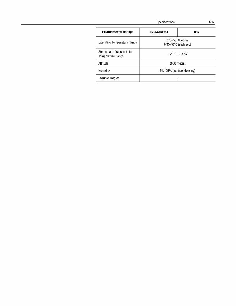
Specifications A-5
Environmental Ratings UL/CSA/NEMA IEC
Operating Temperature Range0°C–50°C (open)
0°C–40°C (enclosed)
Storage and Transportation Temperature Range
–20°C–+75°C
Altitude 2000 meters
Humidity 5%–95% (nonñcondensing)
Pollution Degree 2

A-6 Specifications
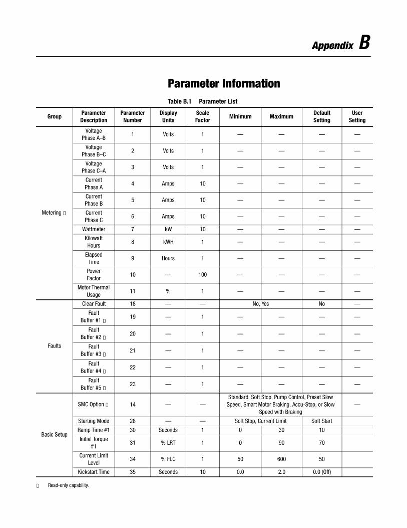
Appendix B
Parameter InformationTable B.1 Parameter List
① Read-only capability.
GroupParameterDescription
ParameterNumber
Display Units
ScaleFactor
Minimum MaximumDefaultSetting
UserSetting
Metering ①
VoltagePhase A–B
1 Volts 1 — — — —
VoltagePhase B–C
2 Volts 1 — — — —
VoltagePhase C–A
3 Volts 1 — — — —
CurrentPhase A
4 Amps 10 — — — —
CurrentPhase B
5 Amps 10 — — — —
CurrentPhase C
6 Amps 10 — — — —
Wattmeter 7 kW 10 — — — —
KilowattHours
8 kWH 1 — — — —
ElapsedTime
9 Hours 1 — — — —
PowerFactor
10 — 100 — — — —
Motor Thermal Usage
11 % 1 — — — —
Faults
Clear Fault 18 — — No, Yes No —
FaultBuffer #1 ①
19 — 1 — — — —
FaultBuffer #2 ①
20 — 1 — — — —
FaultBuffer #3 ①
21 — 1 — — — —
FaultBuffer #4 ①
22 — 1 — — — —
FaultBuffer #5 ①
23 — 1 — — — —
Basic Setup
SMC Option ① 14 — —Standard, Soft Stop, Pump Control, Preset Slow
Speed, Smart Motor Braking, Accu-Stop, or Slow Speed with Braking
—
Starting Mode 28 — — Soft Stop, Current Limit Soft Start
Ramp Time #1 30 Seconds 1 0 30 10
Initial Torque #1
31 % LRT 1 0 90 70
Current Limit Level
34 % FLC 1 50 600 50
Kickstart Time 35 Seconds 10 0.0 2.0 0.0 (Off)
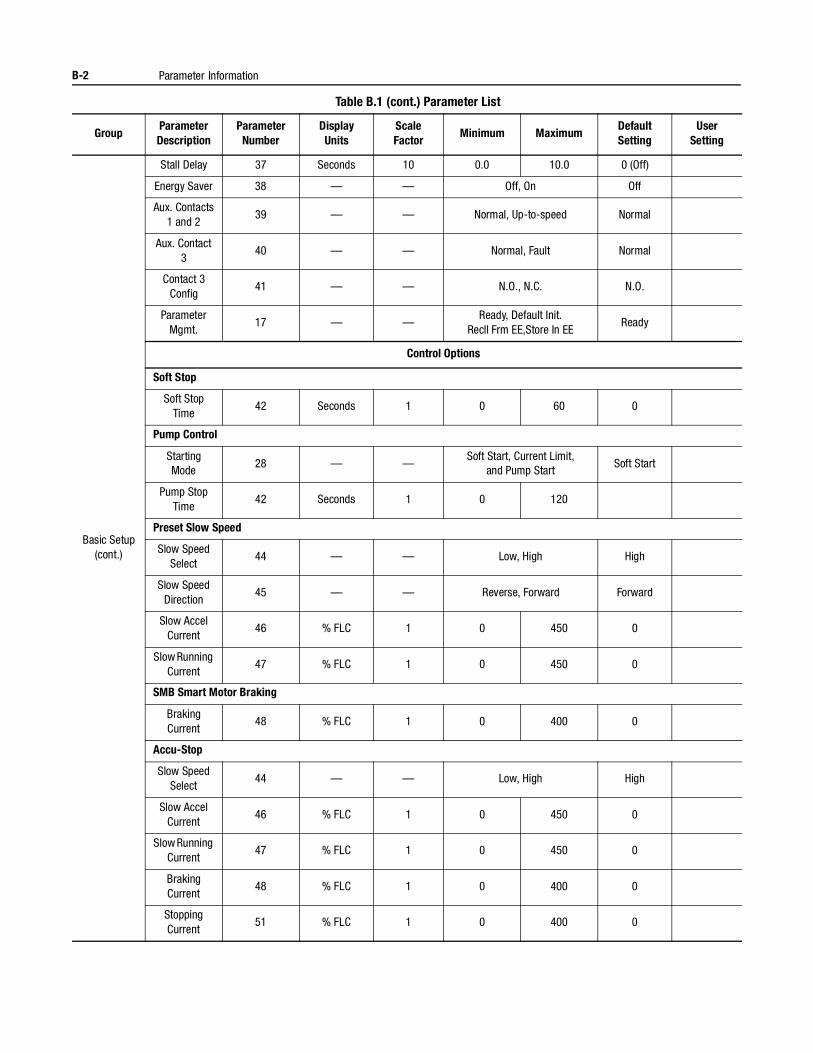
B-2 Parameter Information
Table B.1 (cont.) Parameter List
GroupParameterDescription
ParameterNumber
Display Units
ScaleFactor
Minimum MaximumDefaultSetting
UserSetting
Basic Setup(cont.)
Stall Delay 37 Seconds 10 0.0 10.0 0 (Off)
Energy Saver 38 — — Off, On Off
Aux. Contacts1 and 2
39 — — Normal, Up-to-speed Normal
Aux. Contact 3
40 — — Normal, Fault Normal
Contact 3Config
41 — — N.O., N.C. N.O.
Parameter Mgmt.
17 — —Ready, Default Init.
Recll Frm EE,Store In EEReady
Control Options
Soft Stop
Soft Stop Time
42 Seconds 1 0 60 0
Pump Control
Starting Mode
28 — —Soft Start, Current Limit,
and Pump StartSoft Start
Pump Stop Time
42 Seconds 1 0 120
Preset Slow Speed
Slow Speed Select
44 — — Low, High High
Slow Speed Direction
45 — — Reverse, Forward Forward
Slow Accel Current
46 % FLC 1 0 450 0
Slow Running Current
47 % FLC 1 0 450 0
SMB Smart Motor Braking
Braking Current
48 % FLC 1 0 400 0
Accu-Stop
Slow Speed Select
44 — — Low, High High
Slow Accel Current
46 % FLC 1 0 450 0
Slow Running Current
47 % FLC 1 0 450 0
Braking Current
48 % FLC 1 0 400 0
Stopping Current
51 % FLC 1 0 400 0
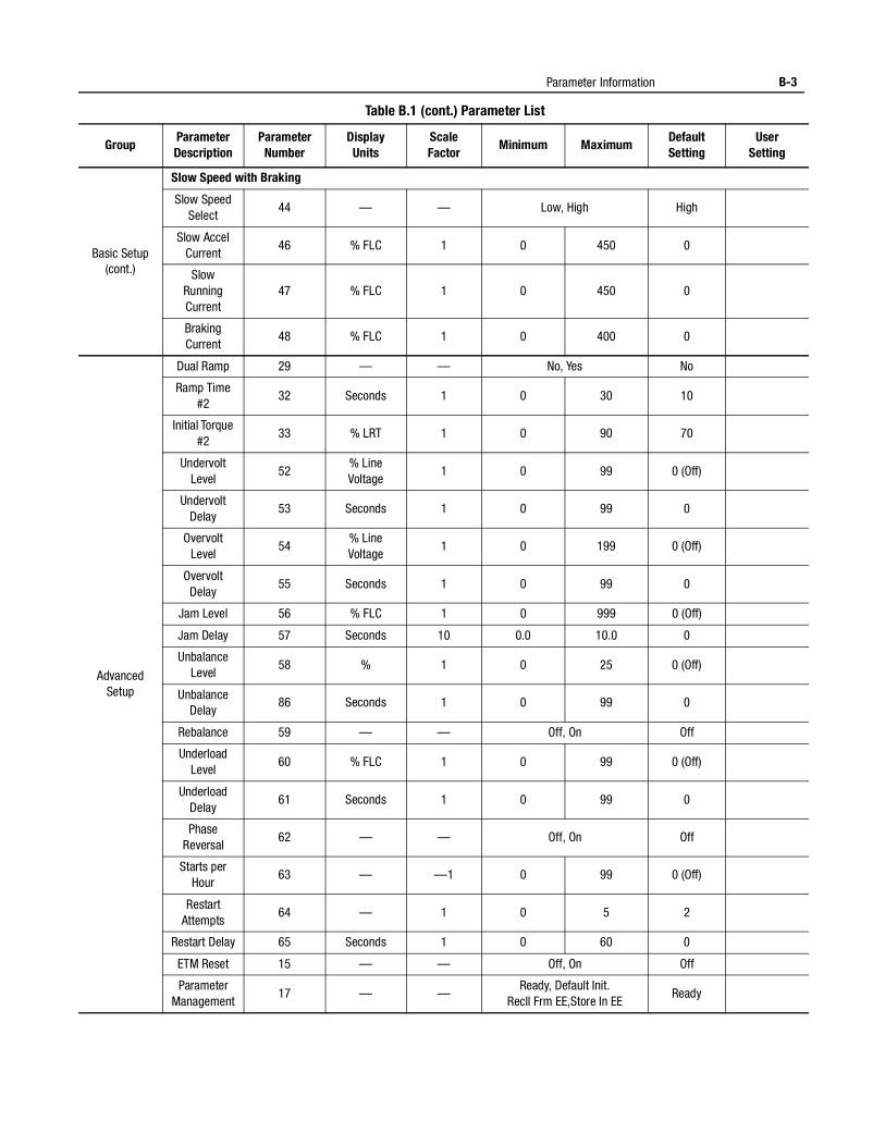
Parameter Information B-3
Table B.1 (cont.) Parameter List
GroupParameterDescription
ParameterNumber
Display Units
ScaleFactor
Minimum MaximumDefaultSetting
UserSetting
Basic Setup(cont.)
Slow Speed with Braking
Slow Speed Select
44 — — Low, High High
Slow Accel Current
46 % FLC 1 0 450 0
Slow Running Current
47 % FLC 1 0 450 0
Braking Current
48 % FLC 1 0 400 0
Advanced Setup
Dual Ramp 29 — — No, Yes No
Ramp Time #2
32 Seconds 1 0 30 10
Initial Torque #2
33 % LRT 1 0 90 70
Undervolt Level
52% Line Voltage
1 0 99 0 (Off)
Undervolt Delay
53 Seconds 1 0 99 0
Overvolt Level
54% Line Voltage
1 0 199 0 (Off)
Overvolt Delay
55 Seconds 1 0 99 0
Jam Level 56 % FLC 1 0 999 0 (Off)
Jam Delay 57 Seconds 10 0.0 10.0 0
Unbalance Level
58 % 1 0 25 0 (Off)
Unbalance Delay
86 Seconds 1 0 99 0
Rebalance 59 — — Off, On Off
Underload Level
60 % FLC 1 0 99 0 (Off)
Underload Delay
61 Seconds 1 0 99 0
Phase Reversal
62 — — Off, On Off
Starts per Hour
63 — —1 0 99 0 (Off)
Restart Attempts
64 — 1 0 5 2
Restart Delay 65 Seconds 1 0 60 0
ETM Reset 15 — — Off, On Off
Parameter Management
17 — —Ready, Default Init.
Recll Frm EE,Store In EEReady
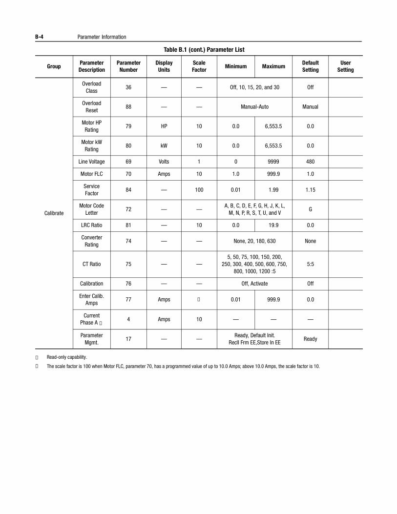
B-4 Parameter Information
Table B.1 (cont.) Parameter List
① Read-only capability.
② The scale factor is 100 when Motor FLC, parameter 70, has a programmed value of up to 10.0 Amps; above 10.0 Amps, the scale factor is 10.
GroupParameterDescription
ParameterNumber
Display Units
ScaleFactor
Minimum MaximumDefaultSetting
UserSetting
Calibrate
Overload Class
36 — — Off, 10, 15, 20, and 30 Off
OverloadReset
88 — — Manual-Auto Manual
Motor HP Rating
79 HP 10 0.0 6,553.5 0.0
Motor kW Rating
80 kW 10 0.0 6,553.5 0.0
Line Voltage 69 Volts 1 0 9999 480
Motor FLC 70 Amps 10 1.0 999.9 1.0
Service Factor
84 — 100 0.01 1.99 1.15
Motor Code Letter
72 — —A, B, C, D, E, F, G, H, J, K, L,
M, N, P, R, S, T, U, and VG
LRC Ratio 81 — 10 0.0 19.9 0.0
Converter Rating
74 — — None, 20, 180, 630 None
CT Ratio 75 — —5, 50, 75, 100, 150, 200,
250, 300, 400, 500, 600, 750, 800, 1000, 1200 :5
5:5
Calibration 76 — — Off, Activate Off
Enter Calib. Amps
77 Amps ② 0.01 999.9 0.0
CurrentPhase A ①
4 Amps 10 — — —
Parameter Mgmt.
17 — —Ready, Default Init.
Recll Frm EE,Store In EEReady
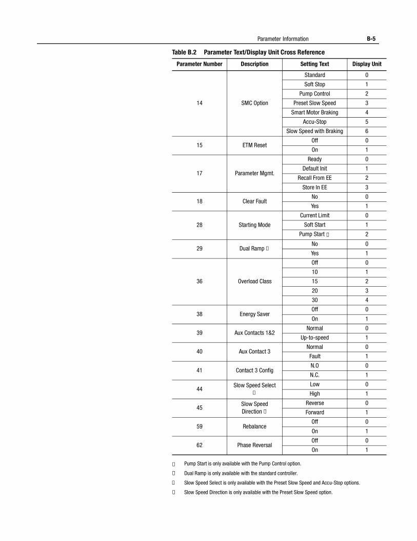
Parameter Information B-5
Table B.2 Parameter Text/Display Unit Cross Reference
① Pump Start is only available with the Pump Control option.
② Dual Ramp is only available with the standard controller.
③ Slow Speed Select is only available with the Preset Slow Speed and Accu-Stop options.
④ Slow Speed Direction is only available with the Preset Slow Speed option.
Parameter Number Description Setting Text Display Unit
14 SMC Option
Standard 0
Soft Stop 1
Pump Control 2
Preset Slow Speed 3
Smart Motor Braking 4
Accu-Stop 5
Slow Speed with Braking 6
15 ETM ResetOff 0
On 1
17 Parameter Mgmt.
Ready 0
Default Init 1
Recall From EE 2
Store In EE 3
18 Clear FaultNo 0
Yes 1
28 Starting Mode
Current Limit 0
Soft Start 1
Pump Start ① 2
29 Dual Ramp ② No 0
Yes 1
36 Overload Class
Off 0
10 1
15 2
20 3
30 4
38 Energy SaverOff 0
On 1
39 Aux Contacts 1&2Normal 0
Up-to-speed 1
40 Aux Contact 3Normal 0
Fault 1
41 Contact 3 ConfigN.O 0
N.C. 1
44Slow Speed Select
③ Low 0
High 1
45Slow Speed Direction ④
Reverse 0
Forward 1
59 RebalanceOff 0
On 1
62 Phase ReversalOff 0
On 1
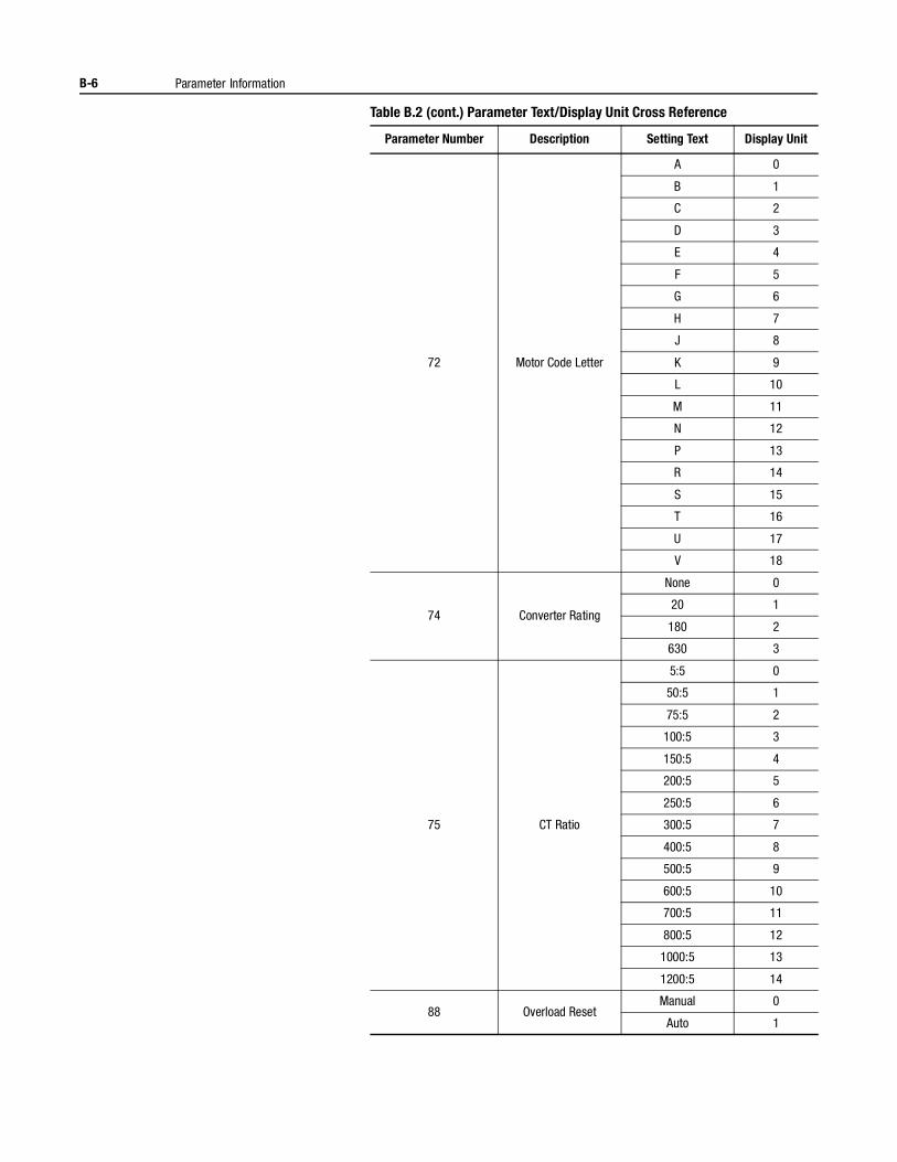
B-6 Parameter Information
Table B.2 (cont.) Parameter Text/Display Unit Cross Reference
Parameter Number Description Setting Text Display Unit
72 Motor Code Letter
A 0
B 1
C 2
D 3
E 4
F 5
G 6
H 7
J 8
K 9
L 10
M 11
N 12
P 13
R 14
S 15
T 16
U 17
V 18
74 Converter Rating
None 0
20 1
180 2
630 3
75 CT Ratio
5:5 0
50:5 1
75:5 2
100:5 3
150:5 4
200:5 5
250:5 6
300:5 7
400:5 8
500:5 9
600:5 10
700:5 11
800:5 12
1000:5 13
1200:5 14
88 Overload ResetManual 0
Auto 1
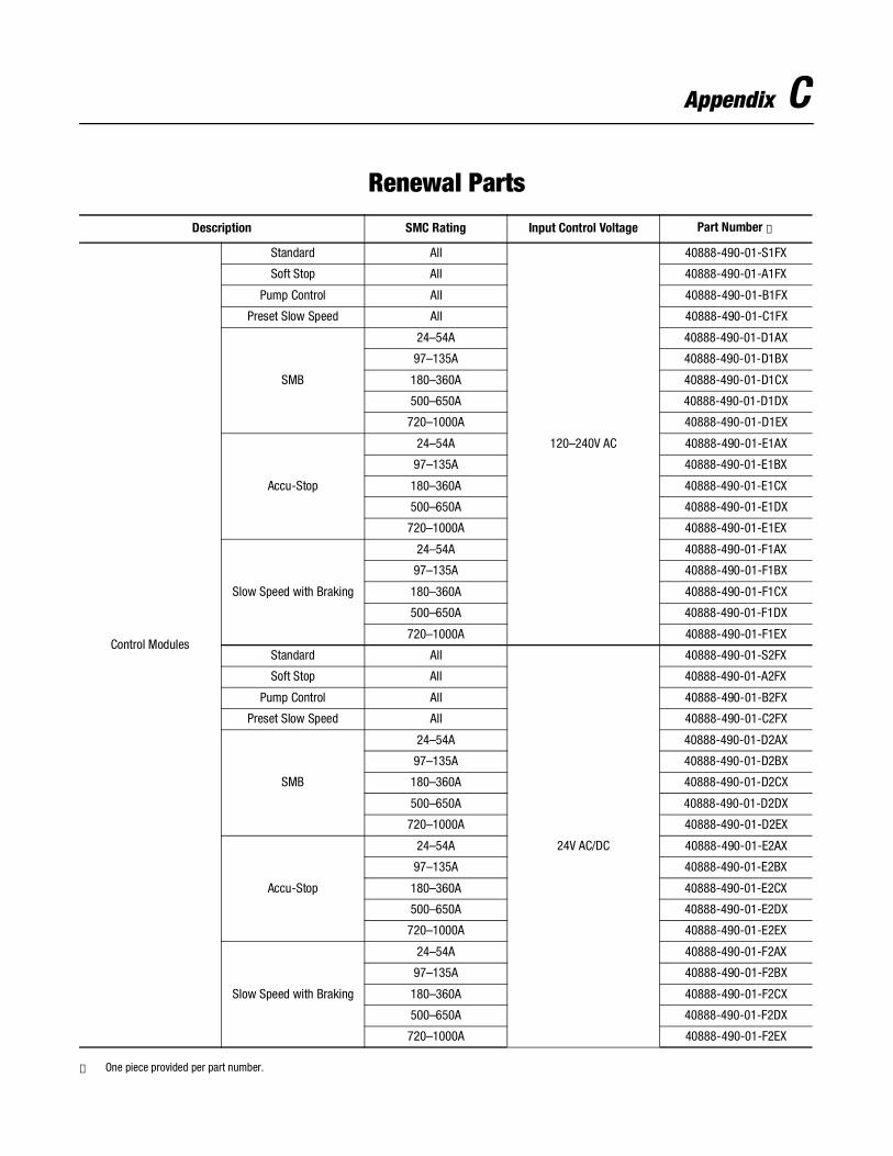
Appendix C
Renewal Parts
① One piece provided per part number.
Description SMC Rating Input Control Voltage Part Number ①
Control Modules
Standard All
120–240V AC
40888-490-01-S1FX
Soft Stop All 40888-490-01-A1FX
Pump Control All 40888-490-01-B1FX
Preset Slow Speed All 40888-490-01-C1FX
SMB
24–54A 40888-490-01-D1AX
97–135A 40888-490-01-D1BX
180–360A 40888-490-01-D1CX
500–650A 40888-490-01-D1DX
720–1000A 40888-490-01-D1EX
Accu-Stop
24–54A 40888-490-01-E1AX
97–135A 40888-490-01-E1BX
180–360A 40888-490-01-E1CX
500–650A 40888-490-01-E1DX
720–1000A 40888-490-01-E1EX
Slow Speed with Braking
24–54A 40888-490-01-F1AX
97–135A 40888-490-01-F1BX
180–360A 40888-490-01-F1CX
500–650A 40888-490-01-F1DX
720–1000A 40888-490-01-F1EX
Standard All
24V AC/DC
40888-490-01-S2FX
Soft Stop All 40888-490-01-A2FX
Pump Control All 40888-490-01-B2FX
Preset Slow Speed All 40888-490-01-C2FX
SMB
24–54A 40888-490-01-D2AX
97–135A 40888-490-01-D2BX
180–360A 40888-490-01-D2CX
500–650A 40888-490-01-D2DX
720–1000A 40888-490-01-D2EX
Accu-Stop
24–54A 40888-490-01-E2AX
97–135A 40888-490-01-E2BX
180–360A 40888-490-01-E2CX
500–650A 40888-490-01-E2DX
720–1000A 40888-490-01-E2EX
Slow Speed with Braking
24–54A 40888-490-01-F2AX
97–135A 40888-490-01-F2BX
180–360A 40888-490-01-F2CX
500–650A 40888-490-01-F2DX
720–1000A 40888-490-01-F2EX
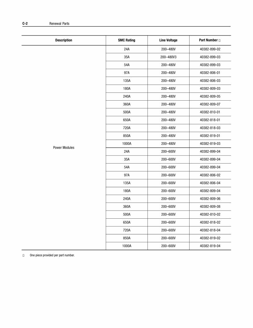
C-2 Renewal Parts
① One piece provided per part number.
Description SMC Rating Line Voltage Part Number ①
Power Modules
24A 200–480V 40382-899-02
35A 200–480V3 40382-899-03
54A 200–480V 40382-899-03
97A 200–480V 40382-806-01
135A 200–480V 40382-806-03
180A 200–480V 40382-809-03
240A 200–480V 40382-809-05
360A 200–480V 40382-809-07
500A 200–480V 40382-810-01
650A 200–480V 40382-818-01
720A 200–480V 40382-818-03
850A 200–480V 40382-819-01
1000A 200–480V 40382-819-03
24A 200–600V 40382-899-04
35A 200–600V 40382-899-04
54A 200–600V 40382-899-04
97A 200–600V 40382-806-02
135A 200–600V 40382-806-04
180A 200–600V 40382-809-04
240A 200–600V 40382-809-06
360A 200–600V 40382-809-08
500A 200–600V 40382-810-02
650A 200–600V 40382-818-02
720A 200–600V 40382-818-04
850A 200–600V 40382-819-02
1000A 200–600V 40382-819-04
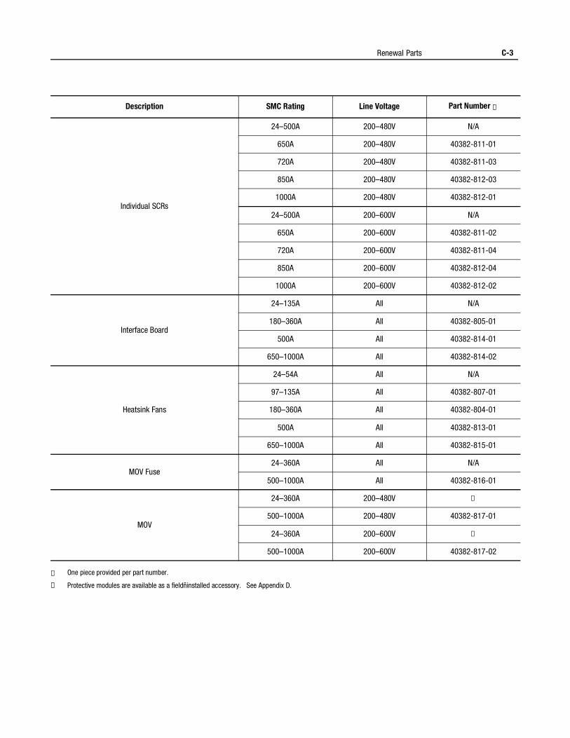
Renewal Parts C-3
① One piece provided per part number.
② Protective modules are available as a fieldñinstalled accessory. See Appendix D.
Description SMC Rating Line Voltage Part Number ①
Individual SCRs
24–500A 200–480V N/A
650A 200–480V 40382-811-01
720A 200–480V 40382-811-03
850A 200–480V 40382-812-03
1000A 200–480V 40382-812-01
24–500A 200–600V N/A
650A 200–600V 40382-811-02
720A 200–600V 40382-811-04
850A 200–600V 40382-812-04
1000A 200–600V 40382-812-02
Interface Board
24–135A All N/A
180–360A All 40382-805-01
500A All 40382-814-01
650–1000A All 40382-814-02
Heatsink Fans
24–54A All N/A
97–135A All 40382-807-01
180–360A All 40382-804-01
500A All 40382-813-01
650–1000A All 40382-815-01
MOV Fuse24–360A All N/A
500–1000A All 40382-816-01
MOV
24–360A 200–480V ②
500–1000A 200–480V 40382-817-01
24–360A 200–600V ②
500–1000A 200–600V 40382-817-02

C-4 Renewal Parts
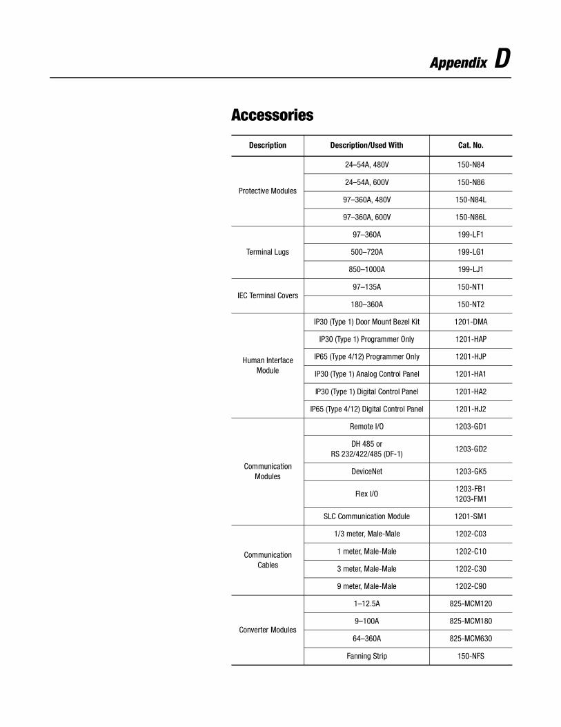
Appendix D
Accessories
Description Description/Used With Cat. No.
Protective Modules
24–54A, 480V 150-N84
24–54A, 600V 150-N86
97–360A, 480V 150-N84L
97–360A, 600V 150-N86L
Terminal Lugs
97–360A 199-LF1
500–720A 199-LG1
850–1000A 199-LJ1
IEC Terminal Covers97–135A 150-NT1
180–360A 150-NT2
Human Interface Module
IP30 (Type 1) Door Mount Bezel Kit 1201-DMA
IP30 (Type 1) Programmer Only 1201-HAP
IP65 (Type 4/12) Programmer Only 1201-HJP
IP30 (Type 1) Analog Control Panel 1201-HA1
IP30 (Type 1) Digital Control Panel 1201-HA2
IP65 (Type 4/12) Digital Control Panel 1201-HJ2
Communication Modules
Remote I/O 1203-GD1
DH 485 orRS 232/422/485 (DF-1)
1203-GD2
DeviceNet 1203-GK5
Flex I/O1203-FB11203-FM1
SLC Communication Module 1201-SM1
Communication Cables
1/3 meter, Male-Male 1202-C03
1 meter, Male-Male 1202-C10
3 meter, Male-Male 1202-C30
9 meter, Male-Male 1202-C90
Converter Modules
1–12.5A 825-MCM120
9–100A 825-MCM180
64–360A 825-MCM630
Fanning Strip 150-NFS
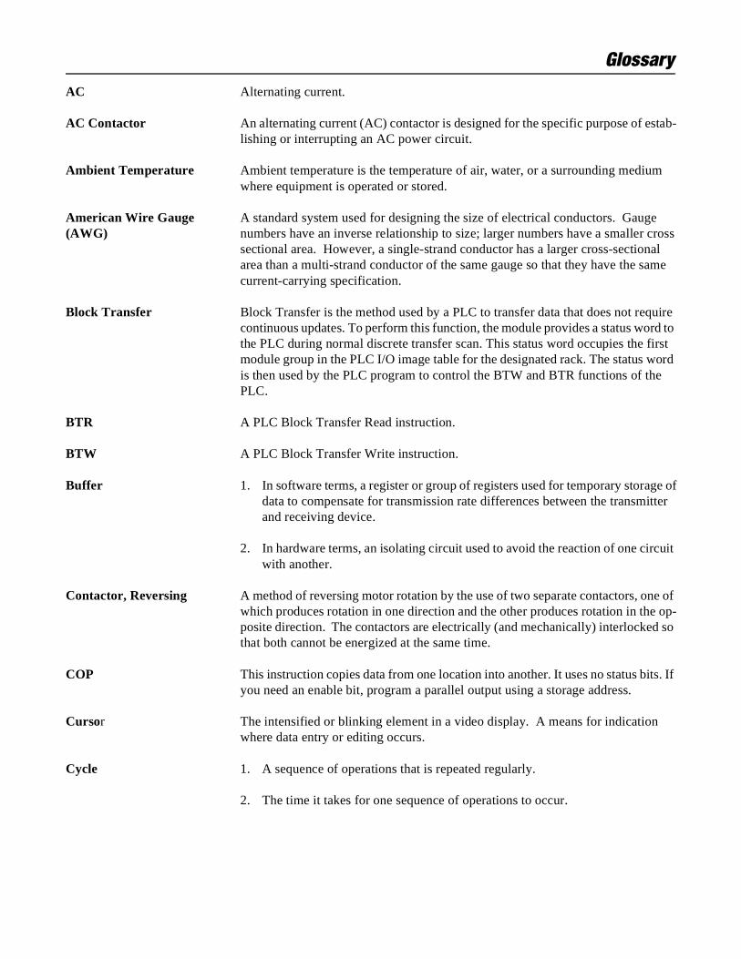
Glossary
AC Alternating current.
AC Contactor An alternating current (AC) contactor is designed for the specific purpose of estab-lishing or interrupting an AC power circuit.
Ambient Temperature Ambient temperature is the temperature of air, water, or a surrounding medium where equipment is operated or stored.
American Wire Gauge A standard system used for designing the size of electrical conductors. Gauge(AWG) numbers have an inverse relationship to size; larger numbers have a smaller cross
sectional area. However, a single-strand conductor has a larger cross-sectionalarea than a multi-strand conductor of the same gauge so that they have the samecurrent-carrying specification.
Block Transfer Block Transfer is the method used by a PLC to transfer data that does not require continuous updates. To perform this function, the module provides a status word to the PLC during normal discrete transfer scan. This status word occupies the first module group in the PLC I/O image table for the designated rack. The status word is then used by the PLC program to control the BTW and BTR functions of the PLC.
BTR A PLC Block Transfer Read instruction.
BTW A PLC Block Transfer Write instruction.
Buffer 1. In software terms, a register or group of registers used for temporary storage ofdata to compensate for transmission rate differences between the transmitterand receiving device.
2. In hardware terms, an isolating circuit used to avoid the reaction of one circuit with another.
Contactor, Reversing A method of reversing motor rotation by the use of two separate contactors, one of which produces rotation in one direction and the other produces rotation in the op-posite direction. The contactors are electrically (and mechanically) interlocked so that both cannot be energized at the same time.
COP This instruction copies data from one location into another. It uses no status bits. If you need an enable bit, program a parallel output using a storage address.
Cursor The intensified or blinking element in a video display. A means for indication where data entry or editing occurs.
Cycle 1. A sequence of operations that is repeated regularly.
2. The time it takes for one sequence of operations to occur.
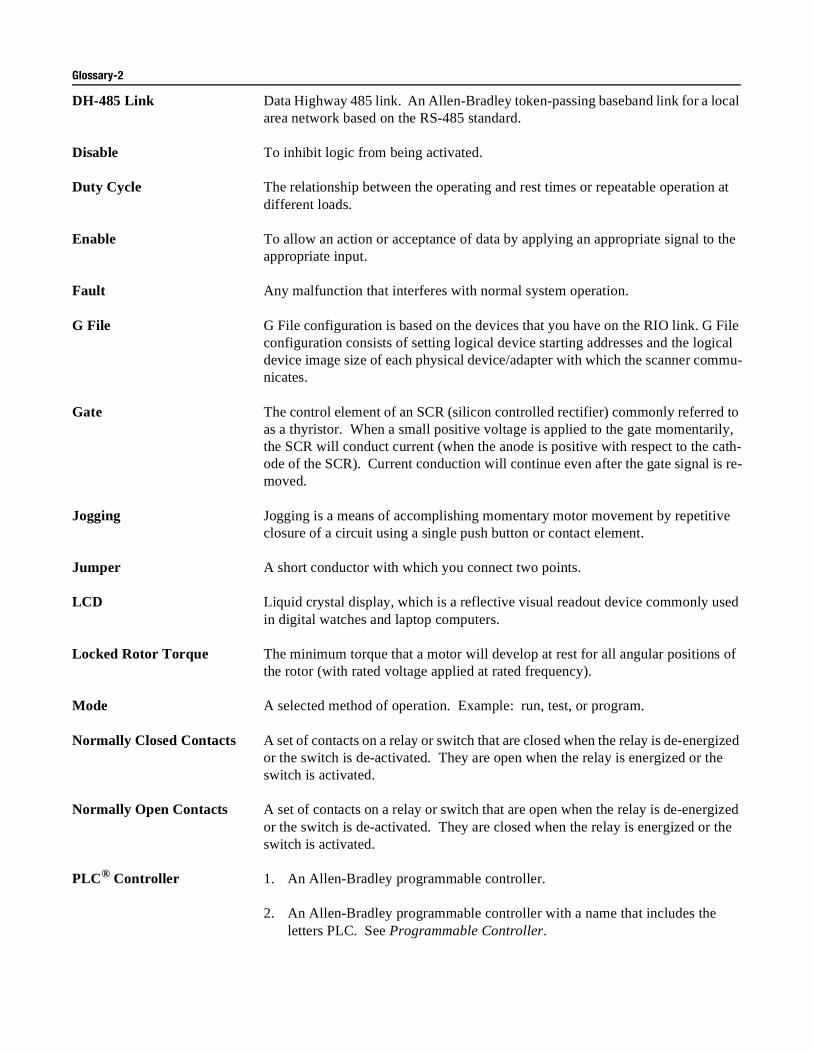
Glossary-2
DH-485 Link Data Highway 485 link. An Allen-Bradley token-passing baseband link for a local area network based on the RS-485 standard.
Disable To inhibit logic from being activated.
Duty Cycle The relationship between the operating and rest times or repeatable operation at different loads.
Enable To allow an action or acceptance of data by applying an appropriate signal to the appropriate input.
Fault Any malfunction that interferes with normal system operation.
G File G File configuration is based on the devices that you have on the RIO link. G File configuration consists of setting logical device starting addresses and the logical device image size of each physical device/adapter with which the scanner commu-nicates.
Gate The control element of an SCR (silicon controlled rectifier) commonly referred to as a thyristor. When a small positive voltage is applied to the gate momentarily, the SCR will conduct current (when the anode is positive with respect to the cath-ode of the SCR). Current conduction will continue even after the gate signal is re-moved.
Jogging Jogging is a means of accomplishing momentary motor movement by repetitive closure of a circuit using a single push button or contact element.
Jumper A short conductor with which you connect two points.
LCD Liquid crystal display, which is a reflective visual readout device commonly used in digital watches and laptop computers.
Locked Rotor Torque The minimum torque that a motor will develop at rest for all angular positions of the rotor (with rated voltage applied at rated frequency).
Mode A selected method of operation. Example: run, test, or program.
Normally Closed Contacts A set of contacts on a relay or switch that are closed when the relay is de-energized or the switch is de-activated. They are open when the relay is energized or the switch is activated.
Normally Open Contacts A set of contacts on a relay or switch that are open when the relay is de-energized or the switch is de-activated. They are closed when the relay is energized or the switch is activated.
PLC® Controller 1. An Allen-Bradley programmable controller.
2. An Allen-Bradley programmable controller with a name that includes the letters PLC. See Programmable Controller.
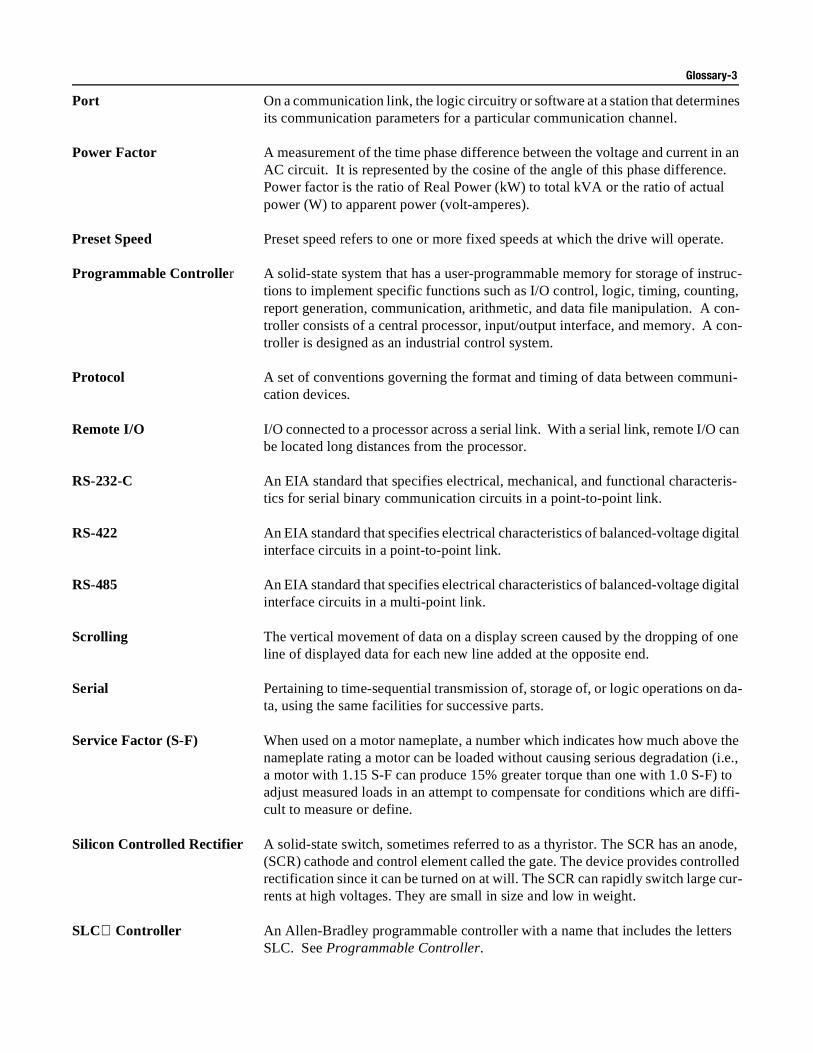
Glossary-3
Port On a communication link, the logic circuitry or software at a station that determines its communication parameters for a particular communication channel.
Power Factor A measurement of the time phase difference between the voltage and current in an AC circuit. It is represented by the cosine of the angle of this phase difference. Power factor is the ratio of Real Power (kW) to total kVA or the ratio of actual power (W) to apparent power (volt-amperes).
Preset Speed Preset speed refers to one or more fixed speeds at which the drive will operate.
Programmable Controller A solid-state system that has a user-programmable memory for storage of instruc-tions to implement specific functions such as I/O control, logic, timing, counting, report generation, communication, arithmetic, and data file manipulation. A con-troller consists of a central processor, input/output interface, and memory. A con-troller is designed as an industrial control system.
Protocol A set of conventions governing the format and timing of data between communi-cation devices.
Remote I/O I/O connected to a processor across a serial link. With a serial link, remote I/O can be located long distances from the processor.
RS-232-C An EIA standard that specifies electrical, mechanical, and functional characteris-tics for serial binary communication circuits in a point-to-point link.
RS-422 An EIA standard that specifies electrical characteristics of balanced-voltage digital interface circuits in a point-to-point link.
RS-485 An EIA standard that specifies electrical characteristics of balanced-voltage digital interface circuits in a multi-point link.
Scrolling The vertical movement of data on a display screen caused by the dropping of one line of displayed data for each new line added at the opposite end.
Serial Pertaining to time-sequential transmission of, storage of, or logic operations on da-ta, using the same facilities for successive parts.
Service Factor (S-F) When used on a motor nameplate, a number which indicates how much above the nameplate rating a motor can be loaded without causing serious degradation (i.e., a motor with 1.15 S-F can produce 15% greater torque than one with 1.0 S-F) to adjust measured loads in an attempt to compensate for conditions which are diffi-cult to measure or define.
Silicon Controlled Rectifier A solid-state switch, sometimes referred to as a thyristor. The SCR has an anode, (SCR) cathode and control element called the gate. The device provides controlled rectification since it can be turned on at will. The SCR can rapidly switch large cur-rents at high voltages. They are small in size and low in weight.
SLC Controller An Allen-Bradley programmable controller with a name that includes the letters SLC. See Programmable Controller.
Glossary-4
Status The condition at a particular time of any numerous entities within a system. These conditions may be represented by values in a status line.
Surge Protection The process of absorbing and clipping voltage transients on an incoming AC line or control circuit. MOVs (Metal Oxide Varistors) and specially designed R-C net-works are usually used to accomplish this.
Toggle To switch alternately between two possible selections.
Transient A momentary deviation in an electrical or mechanical system.
UL Underwriters Laboratories (an approval agency).
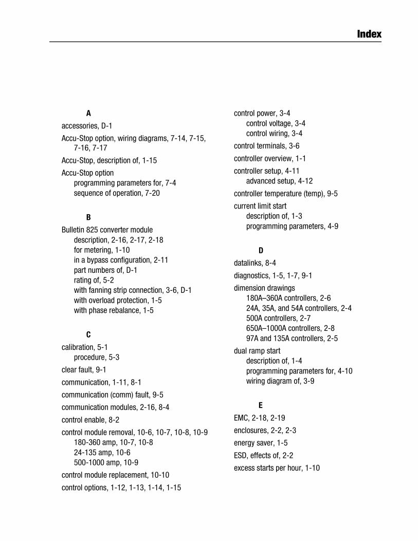
Index
A
accessories, D-1
Accu-Stop option, wiring diagrams, 7-14, 7-15, 7-16, 7-17
Accu-Stop, description of, 1-15
Accu-Stop optionprogramming parameters for, 7-4sequence of operation, 7-20
B
Bulletin 825 converter moduledescription, 2-16, 2-17, 2-18for metering, 1-10in a bypass configuration, 2-11part numbers of, D-1rating of, 5-2with fanning strip connection, 3-6, D-1with overload protection, 1-5with phase rebalance, 1-5
C
calibration, 5-1procedure, 5-3
clear fault, 9-1
communication, 1-11, 8-1
communication (comm) fault, 9-5
communication modules, 2-16, 8-4
control enable, 8-2
control module removal, 10-6, 10-7, 10-8, 10-9180-360 amp, 10-7, 10-824-135 amp, 10-6500-1000 amp, 10-9
control module replacement, 10-10
control options, 1-12, 1-13, 1-14, 1-15
control power, 3-4control voltage, 3-4control wiring, 3-4
control terminals, 3-6
controller overview, 1-1
controller setup, 4-11advanced setup, 4-12
controller temperature (temp), 9-5
current limit startdescription of, 1-3programming parameters, 4-9
D
datalinks, 8-4
diagnostics, 1-5, 1-7, 9-1
dimension drawings180A–360A controllers, 2-624A, 35A, and 54A controllers, 2-4500A controllers, 2-7650A–1000A controllers, 2-897A and 135A controllers, 2-5
dual ramp startdescription of, 1-4programming parameters for, 4-10wiring diagram of, 3-9
E
EMC, 2-18, 2-19
enclosures, 2-2, 2-3
energy saver, 1-5
ESD, effects of, 2-2
excess starts per hour, 1-10
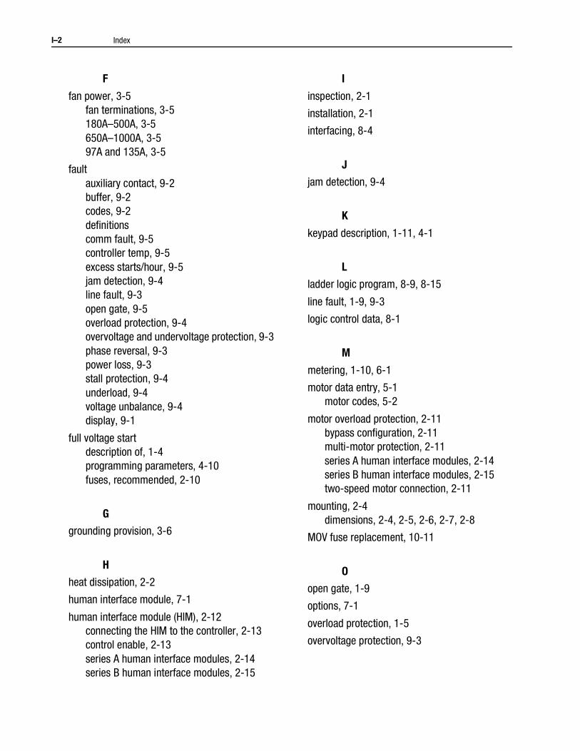
I–2 Index
F
fan power, 3-5fan terminations, 3-5180A–500A, 3-5650A–1000A, 3-597A and 135A, 3-5
faultauxiliary contact, 9-2buffer, 9-2codes, 9-2definitionscomm fault, 9-5controller temp, 9-5excess starts/hour, 9-5jam detection, 9-4line fault, 9-3open gate, 9-5overload protection, 9-4overvoltage and undervoltage protection, 9-3phase reversal, 9-3power loss, 9-3stall protection, 9-4underload, 9-4voltage unbalance, 9-4display, 9-1
full voltage startdescription of, 1-4programming parameters, 4-10fuses, recommended, 2-10
G
grounding provision, 3-6
H
heat dissipation, 2-2
human interface module, 7-1
human interface module (HIM), 2-12connecting the HIM to the controller, 2-13control enable, 2-13series A human interface modules, 2-14series B human interface modules, 2-15
I
inspection, 2-1
installation, 2-1
interfacing, 8-4
J
jam detection, 9-4
K
keypad description, 1-11, 4-1
L
ladder logic program, 8-9, 8-15
line fault, 1-9, 9-3
logic control data, 8-1
M
metering, 1-10, 6-1
motor data entry, 5-1motor codes, 5-2
motor overload protection, 2-11bypass configuration, 2-11multi-motor protection, 2-11series A human interface modules, 2-14series B human interface modules, 2-15two-speed motor connection, 2-11
mounting, 2-4dimensions, 2-4, 2-5, 2-6, 2-7, 2-8
MOV fuse replacement, 10-11
O
open gate, 1-9
options, 7-1
overload protection, 1-5
overvoltage protection, 9-3
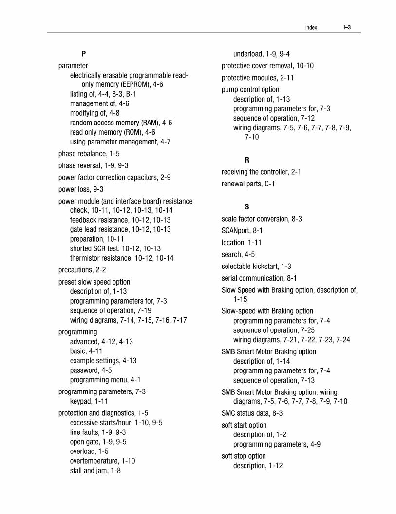
Index I–3
P
parameterelectrically erasable programmable read-
only memory (EEPROM), 4-6listing of, 4-4, 8-3, B-1management of, 4-6modifying of, 4-8random access memory (RAM), 4-6read only memory (ROM), 4-6using parameter management, 4-7
phase rebalance, 1-5
phase reversal, 1-9, 9-3
power factor correction capacitors, 2-9
power loss, 9-3
power module (and interface board) resistance check, 10-11, 10-12, 10-13, 10-14feedback resistance, 10-12, 10-13gate lead resistance, 10-12, 10-13preparation, 10-11shorted SCR test, 10-12, 10-13thermistor resistance, 10-12, 10-14
precautions, 2-2
preset slow speed optiondescription of, 1-13programming parameters for, 7-3sequence of operation, 7-19wiring diagrams, 7-14, 7-15, 7-16, 7-17
programmingadvanced, 4-12, 4-13basic, 4-11example settings, 4-13password, 4-5programming menu, 4-1
programming parameters, 7-3keypad, 1-11
protection and diagnostics, 1-5excessive starts/hour, 1-10, 9-5line faults, 1-9, 9-3open gate, 1-9, 9-5overload, 1-5overtemperature, 1-10stall and jam, 1-8
underload, 1-9, 9-4
protective cover removal, 10-10
protective modules, 2-11
pump control optiondescription of, 1-13programming parameters for, 7-3sequence of operation, 7-12wiring diagrams, 7-5, 7-6, 7-7, 7-8, 7-9,
7-10
R
receiving the controller, 2-1
renewal parts, C-1
S
scale factor conversion, 8-3
SCANport, 8-1
location, 1-11
search, 4-5
selectable kickstart, 1-3
serial communication, 8-1
Slow Speed with Braking option, description of, 1-15
Slow-speed with Braking optionprogramming parameters for, 7-4sequence of operation, 7-25wiring diagrams, 7-21, 7-22, 7-23, 7-24
SMB Smart Motor Braking optiondescription of, 1-14programming parameters for, 7-4sequence of operation, 7-13
SMB Smart Motor Braking option, wiring diagrams, 7-5, 7-6, 7-7, 7-8, 7-9, 7-10
SMC status data, 8-3
soft start optiondescription of, 1-2programming parameters, 4-9
soft stop optiondescription, 1-12
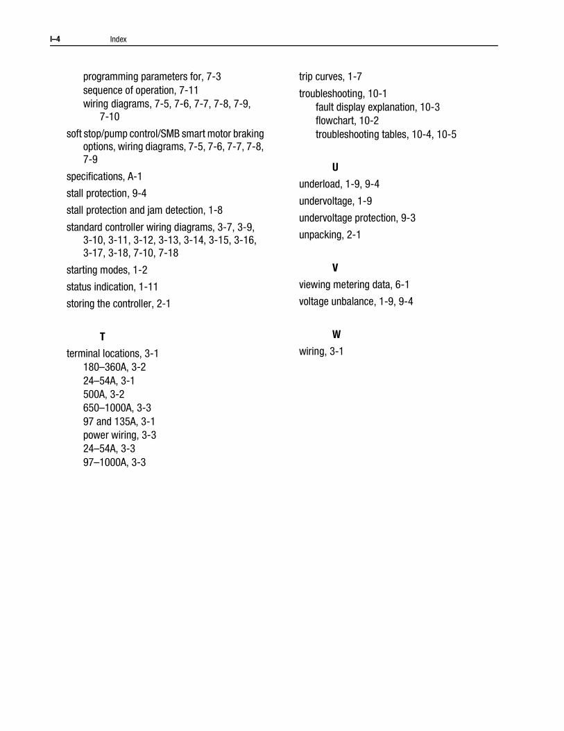
I–4 Index
programming parameters for, 7-3sequence of operation, 7-11wiring diagrams, 7-5, 7-6, 7-7, 7-8, 7-9,
7-10
soft stop/pump control/SMB smart motor braking options, wiring diagrams, 7-5, 7-6, 7-7, 7-8, 7-9
specifications, A-1
stall protection, 9-4
stall protection and jam detection, 1-8
standard controller wiring diagrams, 3-7, 3-9, 3-10, 3-11, 3-12, 3-13, 3-14, 3-15, 3-16,3-17, 3-18, 7-10, 7-18
starting modes, 1-2
status indication, 1-11
storing the controller, 2-1
T
terminal locations, 3-1180–360A, 3-224–54A, 3-1500A, 3-2650–1000A, 3-397 and 135A, 3-1power wiring, 3-324–54A, 3-397–1000A, 3-3
trip curves, 1-7
troubleshooting, 10-1fault display explanation, 10-3flowchart, 10-2troubleshooting tables, 10-4, 10-5
U
underload, 1-9, 9-4
undervoltage, 1-9
undervoltage protection, 9-3
unpacking, 2-1
V
viewing metering data, 6-1
voltage unbalance, 1-9, 9-4
W
wiring, 3-1

Publication 0150-5.3 - October 1998 Supersedes Publication 0150-5.3 - September 1996
40055-145-01(C) 1998 Rockwell International. All Rights Reserved. Printed in USA