Embed Size (px)
Citation preview

Snackshop AP 113Dixie Narco® 501EAMSUSII N T E R N A T I O N A L
®
™
User’s Manual
p o w e r e d b y

| iii
VE CONNECT™ USER MANUAL© Vendors Exchange International, Inc.™
Thank you for purchasing the VE CONNECT™ . This document
will guide you through setting up a VE CONNECT™ on location
for the first time. Note that if not already configured prior to
delivery, the VE CONNECT™ requires an internet connection to
the equipment, as well as a CMS (Content Management System)
account pre configured for the content (product images/
information, categories, themes, and advertisements) specific to
the machine that you are setting up. This guide does not include
information about setting up and using the CMS. Please refer
to the CMS User’s Guide for information related to content or
contact your sales representative for more information.
NOTE: Images may vary slightly from actual product. Instructions
and screenshots may have differences based on the software version
installed on the equipment and the application.

iv | | 1Contents1 Product Overview 2
VE CONNECT™ - What is It? . . . . . . . . . . . . . . . . 2
VE CONNECT™ - How it Works . . . . . . . . . . . . . . . 2
Components . . . . . . . . . . . . . . . . . . . . . . . 3
Primary Components . . . . . . . . . . . . . . . . . . 3
Secondary Components . . . . . . . . . . . . . . . . 4
2 System Setup 5
Unpacking . . . . . . . . . . . . . . . . . . . . . . . . 5
Machine Placement . . . . . . . . . . . . . . . . . . . . 5
Temperature Considerations . . . . . . . . . . . . . . 6
Power Considerations. . . . . . . . . . . . . . . . . . 6
Adding Payment Systems . . . . . . . . . . . . . . . . . 6
Filling Machine . . . . . . . . . . . . . . . . . . . . . . 7
Internet Connection . . . . . . . . . . . . . . . . . . . . 7
Ethernet Cable (RJ45) . . . . . . . . . . . . . . . . . . 7
Wi-Fi Setup . . . . . . . . . . . . . . . . . . . . . . . . 8
Cellular Data Connection . . . . . . . . . . . . . . . . . 12
3 Operator Settings 14
Tray Configuration . . . . . . . . . . . . . . . . . . . . . 16
UCB™ Configuration . . . . . . . . . . . . . . . . . . . . 18
Firmware Version . . . . . . . . . . . . . . . . . . . . 19
Homing Motor to NO (Dixie Narco®501E only) . . . . . . 21
Setting Temperature . . . . . . . . . . . . . . . . . . 21
Clear Sold Out . . . . . . . . . . . . . . . . . . . . . . . 21
System Information . . . . . . . . . . . . . . . . . . . . 21
4 Equipment Testing 23
Testing Images and Content . . . . . . . . . . . . . . . . 23
Test Internet Connection . . . . . . . . . . . . . . . . . 24
Test Camera . . . . . . . . . . . . . . . . . . . . . . . . 24
Test QR Barcode Scanner . . . . . . . . . . . . . . . . . 25
Test the Drop Sensor . . . . . . . . . . . . . . . . . . . 25
5 Operating Equipment 27
Restocking . . . . . . . . . . . . . . . . . . . . . . . . 27
DEX. . . . . . . . . . . . . . . . . . . . . . . . . . . . 27
Cleaning the Display Module . . . . . . . . . . . . . . 28
Cleaning the CPU Module. . . . . . . . . . . . . . . . 28
6 Basic Troubleshooting 29
7 Warranty information 36
8 Connection Diagrams 38
Power Diagram . . . . . . . . . . . . . . . . . . . . . . 38
Audio/Video Connections . . . . . . . . . . . . . . . . . 39
USB Connections . . . . . . . . . . . . . . . . . . . . . 40
Control Board Connections . . . . . . . . . . . . . . . . 41
9 Part Diagrams 42
CPU Module Explosion 1. . . . . . . . . . . . . . . . . . 42
CPU Module Explosion 2. . . . . . . . . . . . . . . . . . 43
Display Explosion . . . . . . . . . . . . . . . . . . . . . 44

| 3
VE CONNECT™ - What is It?The VE CONNECT™ consists of a powerful Intel based computer system, a large format touch panel LCD, and software that transforms traditional vending equipment into an interactive consumer experience. The screen presents the items inside the vending machine in a digital format, and provides information previously inaccessible to the consumer prior to purchasing goods. In addition, the VE CONNECT™ plays video advertisements to the customer and offers new ways to interact with and entice the customer at the point of sale. Internet connection to the equipment is required through Ethernet, Wi-fi or optional cellular service. The VE CONNECT™ is a revolution in vending and brings legacy equipment into the digital age, and is a powerful tool for operators to improve their business.
VE CONNECT™ - How it WorksThe LCD display plays video advertisements and animates products to attract customers (also known as “Attract Mode”). Consumers navigate the UI (User Interface) to view and make product selections using the touch panel. Payment is inserted as normal and currency information is detailed on the screen. Product is vended and customers take their goods. Post vend applications may run, such as skill or chance based games to entice customers to return. Loyalty programs may be available for returning customers, which can be redeemed using the QR code scanner. High quality images and attractive user interfaces are possible because of the quality of the processor and display featured on the VE CONNECT™ .
Route personnel fill vending equipment as usual and then assign tray locations for specific goods using the operator menu. Product images and information are downloaded through an internet connection and reside on the local hard drive of the machine. Changes made to products, such as introducing new products to the machine, require interaction with CMS (Content Management System)and cannot be done directly on the equipment. User experience elements such as themes, games, and loyalty programs are also only set through the CMS. Tray configuration, product mapping, and pricing is set digitally using the Operator Menu on the screen, which is the primary tool for the route manager in setting up and maintaining the equipment.
ComponentsWhat is included with the VE CONNECT™ varies based on the type of vending equipment being used. There are three primary components that make a VE CONNECT™ : the display module, the CPU module, and an adapter kit. A possible secondary component required for VE CONNECT™ installation is a REVISION™ Door, which includes a UCB™.
Primary ComponentsDisplay Module - includes a 46” LCD display in a custom aluminum frame, a multi point touch panel, a camera, a proximity sensor, frame lighting LEDs, a QR code scanner, a speaker, and a USB hub.
CPU Module - includes a miniATX motherboard, integrated hard drive, 24V power supply, 12V power supply,
19V power supply, locking case, keys, cooling fans, keyboard, mouse, mounting hardware, laser barcode scanner, wireless router, antennas, Microsoft Windows® license, mounting hardware and an optional cellular device.
1 Product Overview
CAMERAPROXIMITY SENSOR
SPEAKER
MEDIA MODULE
12 V POWER SUPPLY 19 V POWER SUPPLY MOTHERBOARDCOOLING FAN
24 V POWER SUPPLY CRADLEPOINT ROUTER CELL ADAPTER

| 54 |
Adapter Kit – varies based on type of equipment. Includes transition plates and hardware for display module mounting, HDMI cable, 24V power cable, RS232 mounting hardware, RS232 board, AC power cord, and micro USB cable.
Secondary ComponentsREViSiON™ Door - a high quality metal replacement front door for equipment such as the AP 113 and Dixie Narco® 501E. REVISION™ Doors are not required for all OEM equipment, such as an AMS or USI machine. A UCB™ (Universal Control Board) or similar control board from Vendors Exchange® is required for proper vending operation.
UCB™ (Universal Control Board) - replaces the control board of the OEM equipment and handles payment systems through MDB, collects DEX data, runs motor controls, and receives environmental information such as temperature and drop sensor status. The VE CONNECT™ communicates with the UCB™ via a serial connection, provided through the RS232 board included in the adapter kit. The UCB™ also includes a
keypad for manual configurations and an LCD display that is mounted inside the cabinet, only visible to the route personnel.
Drop Sensor – attaches to the vend bucket on either the OEM door or a REVISION™ Door. Verifies that product has vended and triggers out of stock and refund status. A drop sensor is essential for the VE CONNECT™ because the physical product is covered by the display module and is not visible by the consumer. The drop sensor is included with every REVISION™ Door, or included with an adapter kit for OEM equipment where a REVISION™ Door is not required. Laser Scanner – the USB handheld laser scanner is used to scan tray locations and product UPCs to speed up the convenience of assigning products to locations for the VE CONNECT™ . Keyboard/Mouse – a keyboard and mouse are included for service and convenience of data entry, and should be stored in the bottom of the vending machine for route personnel. Two USB ports are easily accessible for the use of these two devices.
2 System Setup
UnpackingRemove the protective film from the display module frame. Open the vending door and remove the Microsoft Windows® license packet from the vend bucket. Save the Microsoft Windows® license packet and store it in a safe place – DO NOT DISCARD.
Machine PlacementAlways refer to the OEM vending machine user manual regarding moving and setting up the machine.
Please consider facts such as the width of the equipment as it relates to fitting through standard doors, machine transportation and handling, and power before attempting delivery and installation.
Depth ConsiderationsThe VE CONNECT™ may add up to an additional 6.25” to the depth of the machine, depending on configuration (depth of display module + depth of computer module.) Make sure to know door widths of a desired location before attempting delivery. The VE CONNECT™ can be ordered with the
computer module on top of your unit which reduces the overall depth.
iMPORTANT! Any vending machine with VE CONNECT™ should be placed in indoor locations only. Outdoor use of any kind, including
outdoor locations with rain protection, will void warranty.

| 76 |
Temperature Considerations1. VE CONNECT™ installed on non-refrigerated machines should be used in environments where the room temperature is 74 degrees Fahrenheit or less if the equipment is vending products that are susceptible to melting.
2. Place the vending machine at least 6" from the back wall.
3. Do not place the vending machine directly under heat generating lights, such as Halogen spot lights.
4. If the VE CONNECT™ is being installed with a bank of machines, place the machine on the far right or far left of the bank if possible.
5. Do not block vending machine ventilation grates and cooling fans.
6. If products are melting in a non-refrigerated machine, place those products on the lowest possible tray. Example: chocolate, if melting, should be moved to 5th to 6th tray of the machine.
Power ConsiderationsThe VE CONNECT™ computer module taps into the AC power running to the machine. Plug the machines normal 3 pin grounded plug into a properly grounded 115V 60HZ outlet only (USA). In order to comply with electrical safety regulations and Underwriters Laboratories requirements, all electrical equipment must be properly polarized and grounded. The VE CONNECT™ will add 1.8 Amps (200 watts) to the draw from the OEM vending machine. An AP 113, operates at 3Amps, so an AP 113 powered by VE CONNECT™ draws approximately 4.8Amps. Do not exceed the limit of circuit breakers in any given location and outlet. Turning on the power to the machine, and thereby the VE CONNECT™, varies by manufacturer.
Adding Payment SystemsThe UCB™ features a standard MDB connection, accessible on the inside of the door near the payment slots. Install payment systems as you would in other vending machines as there is no difference in this regard. If you are installing a credit card swipe system, such as the EPort®, make sure the connection is between the bill acceptor and the coin changer. Place the antenna for dedicated swipe systems and terminals on the inside of the vending door. The VE CONNECT™ router does not negate the need for a separate wireless modem in processing credit card transactions, contact provider for additional details.
Filling MachineOnce you have confirmed that tray configuration is optimal for the products, you are ready to load your products to the trays. It is highly recommended that you refer to the OEM user’s manual for information on proper filling techniques.
Internet ConnectionVE CONNECT™ requires an internet connection to get the most out of the system features. New product images, advertisements, and even important system updates all rely on an internet connection in order to function. There are three ways to get internet to the VE CONNECT™ : Ethernet cable, Wi-Fi, and cellular.
Ethernet Cable (RJ45)If a hard wired Ethernet connection is near the equipment, then the CPU module should be directly connected to the internet. Using the included keys, unlock the CPU module box. Feed the Ethernet cable through one of the slots on the perimeter of the box. Loosen the kepnuts that are holding the metal bracket, feed the cable into the box, and plug into the RJ45 jack found on the CradlePoint device (see figure). Do not connect the cable directly to the motherboard, as the correct port is critical to proper remote management.
MDB CABLE FROM UCB
BILL ACCEPTOR
COIN CHANGER

| 98 |
Step 6 - Enter the password as “password” (all lowercase), then click “LOGIN”.
Step 7 - Click “Internet” and the following drop down menu will appear. Click “Wi-Fi as Wan/Bridge” from drop down.
Wi-Fi SetupWhen using Wi-Fi you will need to have the wireless name and password available to establish a connection. Inquire with the location proprietor for information if you are authorized to use any available wireless connection.
To setup a Wi-Fi connection on VE CONNECT™ :
Step 1 - Connect a USB keyboard to an available USB port on the inside of the door.
Step 2 - Open the door and press F12 key, Microsoft Windows® desktop will appear. If it does not, touch the screen then press ESC.
Step 3 - Press the Microsoft Windows® shortcut key on the keyboard to make the Windows® task bar appear.
Step 4 - Press the Internet Explorer® icon and start the browser.
Step 5 - Log into the router by entering "gateway" into the address bar and press ENTER. This can also be accomplished by entering 10.45.20.1.
NOTE: if previous two methods do not work try 192.168.0.1.
Use this port for direct ethernet connection
Use this port for direct ethernet connection

| 1110 |
Step 8 - Click the “Wi-Fi as WAN” button
Step 9 - Click “Wireless Connection”. Click the “Import” button
Step 10 - Enter the network password in the “WPA Password” field. Click “Submit”.
Step 11 - A pop up message will appear “Settings were successfully applied”. Click “OK”.
Step 12 - After the router connects to your network, you will see green bars with the network signal strength.
Step 13 - You have now successfully connected your CradlePoint router. Click “Logout” to Exit.
Wireless Name

| 1312 |
Step 3: Click the "Internet" drop down screen and select "Connection Manager".
Step 4: Set the priority on screen using the arrows as a guide. Click to change priority. The connection type at the top of the list is the default connection, with the following below as second, third and so forth.
Step 5: Click "Logout" located in the upper right hand corner.
Step 6: Exit the browser and restart Microsoft Windows® or power cycle the machine. Priorities are now saved.
Cellular Data ConnectionIf Ethernet and Wi-Fi are not an option at the chosen venue, then cellular can be added. The disadvantage of cellular is there is a cost associated with the connection, the connection may be weak or unstable, and it may take longer for certain files to download to the machine. Internet connection speed will not affect the consumer experience, the machine will function the same regardless of the speed or quality of the connection. Contact your sales representative for more information on this option.
If the unit was delivered to you with a cellular connection included, you will find the cellular device connected to the CradlePoint router in the CPU module. While there are several methods for achieving cellular connection, at the time of this writing the method is over a USB device which has an antenna running external to the cabinet. Signal will vary by carrier. A simple method to test the service prior to machine installation is to have a mobile device with the same provider (for example Verizon®) and check the phone for the number of bars available.
Setting Internet Connection PriorityThere are three possible internet connection methods mentioned previously in this document. It may be desirable to set the "priority" for each connection type. In most cases, reliability and stability of connection are: 1) Ethernet 2) Wi-Fi and 3) cellular. Locations that already have Wi-Fi or Ethernet should only use cellular as a backup in the scenario where alternative connection is not available.
To set the connection priority, follow these steps:
Step 1: Open the Internet Explorer® browser. See section "Wi-Fi Setup" above to access the CradlePoint settings page.
Step 2: Enter "gateway" into the address bar to run the CradlePoint setup application.
USB cell dongle connectsto CradlePoint router and external antenna

| 1514 |
Pogo MatThe VE CONNECT™ display blocks the consumer’s view of the physical product inside of the vending machine. Since the customer cannot see the location of the product, the route personnel must assign a slot location for each item in the machine.
Press the Pogo Mat button to view a graphical display of all slots available. Your machine will arrive with the pogo mat set up. The only time you need to access the pogo mat is to change the product or pricing.
The screen shot above summarizes all of the products that are available in the vending machine. The route personnel must adjust this information to match the tray locations for each product, as well as, set individual prices. The sequence and numbering of items listed must match the corresponding tray locations. A thumbnail image of each item is shown to graphically represent the physical item.
Click on the desired slot to direct you to the assignment screen. Use the touchscreen scroll bar to scroll through the available products, or begin typing the first letters of the product to filter results.
5 SLOTS, TRAY 1*
5 SLOTS, TRAY 2
5 SLOTS, TRAY 3
5 SLOTS, TRAY 4
5 SLOTS, TRAY 7
10 SLOTS, TRAY 5
5 SLOTS, TRAY 6
3 Operator Settings
The machine will startup, by default, directly into the attract mode. To access the operator menu, open the front door of the machine. The door switch will launch the operator menu application. The operator menu allows access to basic settings for the equipment, and is a necessary tool for the route personnel in setting up and operation.
• Snacks - exits the operator menu and launches the user interface.
• Pogo Mat - adjust settings for product layout (plan-o-gram), and pricing.
• UCB™ Settings - to program features of the UCB™ without using the internal 12 button keypad and display
• Clear Sold Out - to reset the sold out items in the machine during a refill.
• System info - displays system information such as memory use and IP address.
NOTE: The Operator Menu does not provide access to the following functions:
Loading/managing video advertisements (CMS function)
Changing themes (CMS function)
Changing games (CMS function)
Setting up loyalty programs (CMS function)
Setting up new products (CMS function)
Changing categories and descriptions (CMS function)
Setting volume (Windows function, requires a connected keyboard)

| 1716 |
To adjust the tray configuration, follow these steps:
Step 1 - Connect a USB keyboard and mouse to the USB ports on the inside of the door (disconnect laser barcode scanner if connected to one of the available ports).
Tip: you can connect the included USB keyboard if you prefer it to the on screen keyboard.
Click the desired product from the available product list. Then click “Assign to Slot”. To set the price press “Set Price” and use the on screen number pad or keyboard to enter the value, and press “OK” to confirm, which will take you back to the slot selection screen. Repeat this process for all slot locations in the machine. Once the entire plan-o-gram has been set press “Save” Click OK to confirm, and then press “Exit” to return to the root menu. Press “Snacks” to run the user interface and verify that all of the products appear properly on the screen for customer selection.
Tray ConfigurationThe software tray configuration in VE CONNECT™ must match the actual tray configuration. If the tray configuration shown in the Pogo Mat does not match the tray configuration of the machine, the software will need to be adjusted to match.
SLOT LOCATION SCROLL BAR
AVAILABLE PRODUCT
LIST
KEYBOARD
SELECTION AND OPTIONS
Example:5 Columns, Row 1
matches5 Columns, Row 1

| 1918 |
Step 2 - Press F12 and ESC twice, Windows dashboard will appear.
Step 3 - Go to Internet Explorer® and navigate to C:\GVclient\SlotsEditor and run the "SlotsEditor" executable. The interface of the editor will appear, and the existing configuration (if any) can be imported by clicking the ‘Load’ button.
Step 4 - Click the check boxes to enable/disable slots, then click "Save" when finished and confirm the change. Press "Exit."
Step 5 - Press the "Windows icon" and select “Restart” to reboot the machine.
Step 6 - Check Pogo Mat in the Operator Menu to confirm that changes have taken affect.
Firmware VersionThe firmware version of the UCB™ is displayed on the blue LCD display on the inside of the machine momentarily on power up. The firmware version installed on the UCB™ does matter for proper VE CONNECT™ operation. If you are replacing a UCB™ or upgrading a machine with a REVISION™ Door to support VE CONNECT™, you must ensure that the firmware version is 7.2L or higher. Refer to the UCB™ Setup Guide for information on updating the firmware on the UCB™. NOTE: Firmware versions may vary based on machine type and language.
Programming the Drop Sensor
The drop sensor is a critical component in the VE CONNECT™ because customers cannot see the physical product fall from the vending tray into the vend bucket. There are 6 drop sensor modes on the UCB™.
Mode 04 is recommended for VE CONNECT™ on AP 113 and AMS.
To manually set or change the UCB™ drop sensor configuration, follow these steps:
Step 1 - Open the door and locate the UCB™ and keypad.
Step 2 - Press the “Mode” button on the UCB™ harness board located in the corner of the board.
Mode 00 – Off. Drop sensor is not active.
Mode 01 – Credit is returned after one attempt to vend. The selection is not locked out.
Mode 02 – Credit returned after one attempt to vend. Selection is locked out after 3 consecutive failures.
Mode 03 – Credit returned after 1 full cycle attempt and 5 partial turns. The selection is locked out.
Mode 04 – Credit returned after 1 full cycle attempt and 5 partial turns. The selection is not locked out.
Mode 05 –Credit returned after 2 full cycles if vend failed. Selection motor stops when product fails. Use this mode for older
models that do not have a homing switch for motors.
Plug in keyboard and mouse here
UCB™ ConfigurationThere are only a few critical aspects of the UCB™ that need to be considered with the operation of the VE CONNECT™ : firmware version, drop sensor, single vend mode, homing motor, and temperature (for refrigerated units only). UCB™ configuration via software will be available soon in an upcoming software update.
Tip: for more information on the UCB™ functions and controls, refer to the UCB™ user’s manual included with every REVISION™ Door or contact Vendors Exchange® for a digital copy of the guide.

| 2120 |
Step 3 - Press 8, 8, 8, 6, 6 in sequence. The current drop sensor mode will show on the blue LCD screen.
Step 4 - Press the desired mode, (00, 01, 02, 03, 04, or 05) and * to confirm.
Step 5 - Press 4, 4 in sequence to exit.
To manually set or change the UCB™ drop sensor configuration to mode 00 for Dixie Narco® 501E, follow these steps:
Step 1 - Open the door and locate the UCB™ and keypad.
Step 2 - Press the “Mode” button on the UCB™ harness board located in the corner of the board.
Step 3 - Press 8, 8, 8, 6, 6 in sequence. The current drop sensor mode will show on the blue LCD screen.
Step 4 - Press the desired mode, (00, 01, 02, 03, 04, or 05) and * to confirm.
Step 5 - Press 4, 4 in sequence to exit.
Single vend mode to NO
The firmware version and configuration of single vend mode must be correct for proper VE CONNECT™ function.
To check the single vend status follow these steps:
Step 1 - Open the door and locate the UCB™ and keypad.
Step 2 - Press the “Mode” button on the UCB™ harness board located in the corner of the board.
Step 3 - Press 8, 8, 8, *, 8, 7, 0, 0, *, 8, 8 in sequence. The current single vend mode YES or NO will be displayed.
Step 4 - Press 5, * to change to NO if needed.
Step 5 - Press 4, 4 in sequence to exit.
Homing Motor to NO (Dixie Narco®501E only)Homing motor must be set to NO if you are operating a Dixie Narco®501E
Follow these steps to set the motor homing NO:
Step 1 - Open the door and locate the UCB™ and keypad.
Step 2 - Press the “Mode” button on the UCB™ harness board located in the upper right hand corner of the UCB™.
Step 3 - Press 8, 8, 8, 6, 8, 1, *, 4, 4 in sequence. Motor Homing is now set to NO.
Setting TemperatureIf you have a refrigerated unit with a temperature sensor connected to the UCB™ and need to adjust the temperature settings outside of default, it can be changed through the Advanced settings tab on the UCB™. See the UCB™ programming flow chart for details.
Clear Sold OutWhen the UCB™ detects that a particular product has failed to vend (drop sensor is not triggered even after reattempt), the item will display “Sold Out” on the user interface. A route person must inform the system that the tray has been restocked or the “Sold Out” icon will remain and the product will not vend. Pressing the “Clear Sold Out” button on the Operator Menu will clear all the sold out products.
Note that a single item that is in multiple slots (a best seller, for example), will not be marked as “Sold Out” if there is additional product available in alternate trays. Single vend must be set to NO on the UCB™ for this feature to work. For further information about single vend, see the section in this manual detailing UCB™ settings, or refer to the UCB™ Setup Guide.
System InformationThe primary use of system information is to determine if you have an IP address and that your internet connection is functioning.
MODE Button

| 2322 |
Machine VolumeThe VE CONNECT™ uses Windows 7® Embedded as the operating system. To adjust the volume level, you will need to use a keyboard to exit the Snacks application and drop to the desktop.
Follow these steps to change the system volume:
Step 1 - Plug the keyboard into an available USB port on the inside of the door.
Step 2 - Open the door and press F12 key, Windows desktop will appear. If it does not, touch the screen then press ESC.
Step 3 - Press the "Windows key" on the keyboard and touch the task bar at the top of the screen, and select the speaker icon in the upper right.
Step 4 - Use the down or up arrow keys on the keyboard, or slide up or down with your finger. (Arrow keys allow more resolution and control vs finger adjustment). A tone will signal to inform you of the current volume level.
4 Equipment Testing
Testing Images and ContentOnce products have been selected and items loaded into the vendor, it is recommended to view all of the products to make sure you have selected the correct files and that pricing is properly set.
To test the images and content follow these steps:
Step 1 - In the user interface application, press an item to bring it to zoom.
Step 2 - Swipe the product left, right, up, and down to make sure the image matches the product in the machine.
Step 3 - Click “Nutritional Facts” to verify that the nutritional information matches the product.
Step 4 - Repeat this process for all items in the machine.
Test Payment and VendingTesting of payment and vending is highly recommended before leaving the machine to customers. Note that if the coin changer is empty before testing, it will limit the function of the bill acceptor.
To test payment and vending follow these steps:
Step 1 - Make sure there is ample change in the coin changer
Use the up and down arrowson the keyboard, or
adjust with your �nger
Press this button to verify nutritional
information accuracy
Swipe the image left and right, up and down
to verify integrity
| 2524 |
Step 2 - Insert 25 cents into the coin slot, verify that $0.25 credit appears on the LCD Screen.
Step 3 - Insert a $1 bill. Verify that the credit shown is now $1.25.
Step 4 - Select an item and press the “BUY” button. It is recommended to buy something in this example that is less than $1.25 to verify that change is dispensed.
Step 5 - Listen for the motor to turn and product to drop. Payment and vending is functional.
Test Internet ConnectionThere are several ways to test the internet connection. One method is to go to the Windows® desktop and launch Internet Explorer®.
Follow these steps to verify internet connectivity:
Step 1 - Open the door and connect a USB keyboard to an available USB port on the inside of the door.
Step 2 - Press "F12" key, the Windows® desktop will appear. If it does not, touch the screen then press ESC.
Step 3 - Press the Windows shortcut key on the keyboard to make the task bar appear.
Step 4 - Press the Internet Explorer® icon and see if the browser functions and websites are viewable.
Test CameraTo verify the camera is working, follow these steps:
Step 1 - Open the door and connect a USB keyboard to an available USB port on the inside of the door.
Step 2 - Press "F12" key, Windows desktop will appear. If it does not, touch the screen then press "ESC."
Step 3 - Locate the icon on the desktop named “Web Cam Viewer” and press it to start the application.
Step 4 - Press “Connect” and verify that the camera is operational (you should see an image of yourself and the room).
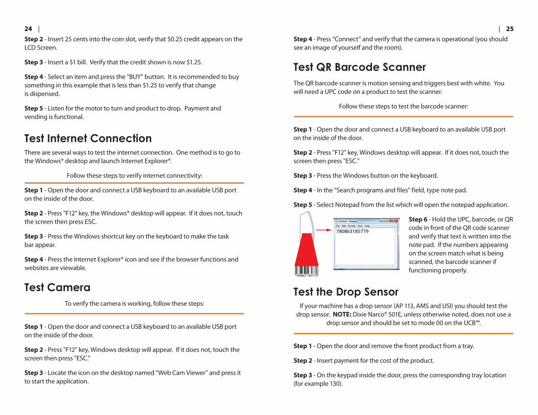
Test QR Barcode ScannerThe QR barcode scanner is motion sensing and triggers best with white. You will need a UPC code on a product to test the scanner.
Follow these steps to test the barcode scanner:
Step 1 - Open the door and connect a USB keyboard to an available USB port on the inside of the door.
Step 2 - Press "F12" key, Windows desktop will appear. If it does not, touch the screen then press "ESC."
Step 3 - Press the Windows button on the keyboard.
Step 4 - In the “Search programs and files” field, type note pad.
Step 5 - Select Notepad from the list which will open the notepad application.
Step 6 - Hold the UPC, barcode, or QR code in front of the QR code scanner and verify that text is written into the note pad. If the numbers appearing on the screen match what is being scanned, the barcode scanner if functioning properly.
Test the Drop SensorIf your machine has a drop sensor (AP 113, AMS and USI) you should test the
drop sensor. NOTE: Dixie Narco® 501E, unless otherwise noted, does not use a drop sensor and should be set to mode 00 on the UCB™.
Step 1 - Open the door and remove the front product from a tray.
Step 2 - Insert payment for the cost of the product.
Step 3 - On the keypad inside the door, press the corresponding tray location (for example 130).
780863185779

| 2726 |
Step 4 - The motor will vend, but product will not fall because you have removed the product. Watch/listen for the motor to make attempts to drop the product. If in Mode 4, it will make 1 full rotation. The product will be marked as Sold Out on the user interface. The drop sensor is working.
Tip: There is a red LED on the drop sensor that goes off when you wave your hand in front of it.
Test Motors through the UCB™Follow these steps to test the motors using the keypad:
With the door open press the "MODE" button on the harness board. The display shows “ACCESS CODE”.
Press "8" until the display reads "SERVICE." Press "6" and the display shows MOTOR TEST. Press "6" again and the display shows "MOTOR TEST: NO." Press any key to toggle between “NO” and “YES”. Press "*" and the display returns to "MOTOR TEST. " To test vend motors choose “YES”,
press "*" then press "4" until the display returns to "SELECT." All selections in the machine are now in test vend mode until the door switch is pressed. To test motors, type the tray locations for each. For example with the AP 113, press “100”, then “110” or “120” depending on tray configuration. Repeat this process for all tray locations to confirm the motors are functioning properly.
Drop sensor ismounted on sidesof vend bucket
Drop sensor ismounted on sides
of vend bucket
5 Operating Equipment
RestockingRestocking the machine with VE CONNECT™ is no different than restocking a traditional vending machine, with the exception that if you make changes to the product tray location you need to update the software according to the new configuration. Also, any items that are “SOLD OUT” need to be refilled and the route personnel must press “Clear Sold Out” from the Operator Menu.
DEXDEX data is stored locally and can be accessed through the standard DEX jack included with the UCB™ and REVISION™ Door. For more information on audit data, please refer to the UCB™ setup guide.
Care and MaintenanceFollow the OEM owner’s documentation for cleaning and maintenance instructions specific to the associated vending machine. For VE CONNECT™ specific care, please consider the following guides.
DEX jack onREVISION™ Door
for an AP 113
MODE Button

| 2928 |
Cleaning the Display ModuleDo not use harsh chemicals to clean the touch panel. The touch panel is constructed with tempered glass, but do not use ammonia based cleaners such as Windex®. The touch panel works by line-of-sight from LEDs along the perimeter of the panel. The LEDs are protected by a dark plastic lens that can be damaged by chemicals.
Use moist towels and mild cleaners only. Dust may build over time on the perimeter lens of the touch panel which may degrade performance. Use a soft cloth for wiping off the perimeter lens as part of a regular maintenance schedule.
Cleaning the CPU ModuleWe recommend cleaning the CPU module at least twice a year to blow out dust that has collected in the housing over time.
Follow these steps to clean the CPU Module:
Step 1 - Power off the machine.
Step 2 - Unlock the CPU module and lift up to remove the cover.
Step 3 - Blow out the CPU module with compressed air, such as canned air. Focus on the fans, motherboard, etc.
Step 4 - Replace the lid and re-lock the housing.
6 Basic Troubleshooting
PROBLEM: Power up equipment and display is locked on a solid blue screen.
There are several possible fixes for this issue.
CHECK 1: Check that the computer is on. Use the included keys to remove the cover of the CPU module (lift up), and look at the fan on the motherboard. If the fan is spinning, then the computer is ON. Check that the HDMI video connection going into the motherboard is not loose. If the fan is not spinning, check that the power cable is secured properly to the board.
CHECK 2: Remove the rear cover and metal deflector (AP 113 only) of the display module by taking off the 4 kepnuts holding the protective cover and rear deflector. Check that the HDMI cable is properly connected. Check that the LVDS cables and power cables are properly seated. Replace the rear cover and power up the machine. If the problem continues contact Vendors Exchange® customer service department.
Is the HDMI cable connected?
Is the fan spinning?
Check LVDS cables are tight
Check thiscable is tight
Check HDMI is connected
For support: 1.855.888.9456 • [email protected]

| 3130 |
PROBLEM: UCB™ communication error. Operator menu informs that system is failing to connect to UCB™.
This error indicates that the software is not able to communicate with the UCB™ over the serial data line.
CHECK 1: Verify that the UCB firmware is version 7.2L or later. Open the door to power up the machine. Watch the blue LED display above the keypad, firmware version will temporarily display.
Check that the connectoris properly seated
CHECK 2: Remove the rear cover of the CPU module (unlock and lift) and check that the data cable is properly seated to the motherboard.
CHECK 3: Remove the UCB™ cover, if present, and verify that the data cable is properly seated into the UCB™. If this does not resolve the problem, please contact Vendors Exchange® customer service department.
CHECK 4: Follow the gray cable from the UCB back to the computer module. There is an in-line 4pin connector. Examine the connector to make sure it is secure and that none of the terminals are loose or broken. Continue to follow the cable to make sure there are no cuts or pinched wires.
PROBLEM: Cannot connect to the internet.
If you are unable to connect to the internet, there are several possible solutions:
Wi-Fi – refer to instructions in this manual for setting and testing internet connection over Wi-Fi. If you have a stable connection, it may be that the internet is not connected to the wireless router of the location. Check with the location manager to discuss.
Cellular – refer to instructions in this manual for setting cellular connection. Check that the USB cable is properly seated into the CradlePoint router by opening the CPU module housing and examining the connection. If you are still unable to get a connection, it may be that the location does not have sufficient reception. Check the position of the cellular antenna on the machine.
PROBLEM: Product is not vending.
CHECK 1: Make sure that the trays are properly seated into the cabinet. Perform a motor test through the UCB™ as described in the section of this manual for the UCB™ and verify that the targeted motor is functioning.
CHECK 2: It may be that UCB™ communication is failing, see section above regarding UCB™ communication.
CHECK 3: Make sure that the product is assigned in the Pogo Mat to the correct slot. Verify that the right tray is assigned to the right product.
PROBLEM: Bill acceptor is not accepting bills.
CHECK 1: Verify that the coin changer has sufficient change. If it is low or empty, the bill acceptor may not function. Add change to the coin changer and reset the machine.
CHECK 2: Verify that the MDB connection is secure and that the bill acceptor is getting power.
CHECK 3: Verify that the bill cartridge is properly seated into the acceptor.
Check that the connector is properly seated
Check that RS232 board and connector are properly connectedCheck that RS232 board and
connector are properly connected
Check that MDB connector is seated and follow the
wire to the bill acceptor MDB.
Check that MDB connector is seated and follow the
wire to the bill acceptor MDB

| 3332 |
PROBLEM: Touchscreen is no longer responding to touching glass.
Reset the machine to see if the problem goes away. If not, plug the USB keyboard into the USB port on the inside of the machine. Look at the keyboard and see if the Number Lock or Caps Lock light up. If so, then you have an issue specific to the touch panel USB connection. If not, then you may have a USB connection issue to the motherboard.
To test the USB connection, open the cover for the CPU module by unlocking and lift up. Verify that the USB cable is plugged into the motherboard. Change to an alternate USB port just to make sure. Retest touch panel. If condition persists contact customer service. Refer to Service Manual for more information.
PROBLEM: Display is not turning on.
If no lights are illuminated on the LCD display (display is black with no lights, possibly the LED perimeter lights as well, it is possible that the display is not getting the required 24V power.) There are two locations where the 24V power is connected.
CHECK 1: Open the cover to the CPU module by unlocking and sliding up. Examine the 24V power supply and look for a green LED light indicating that the supply is ON. Verify that the black and red cables feeding to the inside of the cabinet are both secure.
24V POWER LINESTO DISPLAY MODULE
AC INPUT
GREEN LEDPOWER INDICATOR
GREEN LEDPOWER INDICATOR
24V POWER LINESTO DISPLAY MODULE
AC INPUT
CHECK 2: Power off the machine. Remove the rear cover and deflector plate (AP 113 only) of the display module by removing the 4 kepnuts. Look for the green connector that is connected to the HDMI conversion board. Grab the sides of the green connector and pull downward. Check the cables to make sure they are not frayed or improperly seated. If necessary, use a small screw driver to loosen, re-insert wires, and tighten. NOTE: RED cables go to the right two connections when viewed from the back (see picture below).
PROBLEM: Drop sensor is non-functional.
If the drop sensor is NOT lit when the machine is on, check the connection to the UCB™. Follow the wires from the drop sensor up to the UCB™ and make sure the connection is secure and in the correct port. If the light is still on, closely inspect the WHITE wire to make sure there are no breaks in the cable at the terminals, or cuts/pinches in the line. Make sure the cable is not too tightly stretched in any area of tie-down.
Once electrical connection is confirmed to be correct, and still shows product as Sold Out after failed vend, verify that the drop sensor is enabled in the UCB™ settings. See section in this manual for details about mode 04 for AP 113, AMS.
Check that the green power connector is
properly seated
DROP SENSORCONNECTOR

| 3534 |
PROBLEM: USB keyboard is not detected when connected.
There are two ports on the inside of the door. Try using the other USB port. If that fixes the problem, there may be a loose connection between the USB hub of the display module and the extension cable that reaches the access panel. Remove the rear cover and deflector plate (AP 113 only) of the display module by removing the 4 kepnuts. Examine the USB hub and ensure that it is properly connected and the LED on the hub is lit. Trace the USB cables that go to the external panel and plug both into an alternate USB port on the hub.
Check that cables are seated, change ports
PROBLEM: Product is sold out even after refilling.
Press “Clear Sold Out” in the Operator Menu.
PROBLEM: No sound.
First verify that the video file being played has audio in the mix. Check the volume settings in Microsoft Windows®. See information relating to audio in this manual. If this does not fix the problem, check the audio connections to the HDMI board in the display module. Open the panel and verify the cable is connected to the port shown.
Check that the audioconnector is
properly seated
PROBLEM: Keypad inside of door is not responding to button presses.
If the keypad is not responding to button presses (you should hear a beep) then check the wires connecting the keypad to the UCB™. To access the back of the keypad, remove the 4 kepnuts holding the control panel bracket to the inside of the door. Verify the connections.

| 3736 |
7 Warranty Information
Limited Warranty and Disclaimer. Vendors Exchange International, Inc. (herein referred to as "VE") warrants that the VE CONNECT, including without limitation, it's component part(s) and associated services, sold will be of the kind and quality described herein and will be free of defects in workmanship or material. This Warranty shall extend for the Warranty Period set forth below following the date of delivery of such VE CONNECT. VE MAKES NO WARRANTY, EXPRESS, IMPLIED (INCLUDING BUT NOT LIMITED TO WARRANTIES OF MERCHANTABILITY AND FITNESS FOR INTENDED PURPOSES), OR STATUTORY, OTHER THAN THE FOREGOING EXPRESS WARRANTY.
PRODUCTS WARRANTY PERIOD VE CONNECT™ 1 YEAR
Failure of the Buyer to submit any claim hereunder within ten (10) days following expiration of the Warranty Period applicable to such VE CONNECT shall be an admission by the Buyer and conclusive proof that such articles are in every respect as warranted and shall release VE from any and all claims for damage or loss sustained by the Buyer. In the event the Buyer timely submits a claim for breach of WARRANTY, the parties agree that, at VE’s option, the Buyer’s sole and exclusive remedies shall be the repair or replacement of the defective VE CONNECT or a refund of the price of the defective VE CONNECT.
The Buyer acknowledges that it alone has determined that the VE CONNECT purchased hereunder shall suitably meet the requirements of its intended function. It is expressly understood that any technical advice or recommended operating practices furnished by VE with respect to the use of the VE CONNECT is given without charge, and VE assumes no obligation or liability for the advice or recommended operating practices given, or results obtained, all such advice or recommended operating practices being given and accepted at the Buyer’s risk.
This Warranty does not apply to (i) electrical components, wiring, circuits and/or mechanical parts or assemblies damaged as a result of operating the VE CONNECT at other than 115 volts, 60 Hertz current, (ii) VE CONNECT damaged
due to vandalism, fire, flood or other casualty, (iii) VE CONNECT not maintained in accordance with the manufacturer’s or VE’s recommendations, and/or (iv) VE CONNECT not serviced by VE authorized service personnel or which contain replacement parts not furnished by VE or its authorized service personnel.
Limitation of Liability. VE SHALL NOT BE LIABLE FOR ANY INJURY, LOSS, OR DAMAGE, WHETHER DIRECT, INCIDENTAL, OR CONSEQUENTIAL ARISING OUT OF THE USE OR THE INABILITY TO USE ANY VE CONNECT SOLD BY VE. The remedies of the Buyer set forth herein are exclusive, and the liability of VE with respect to any contract or sale or anything done in connection therewith, whether in contract, in tort, under any warranty, or otherwise, shall not, except as expressly provided herein, exceed the price of the VE CONNECT on which such liability is based. Any statements or representations about the VE CONNECT, other than those contained herein, do not constitute warranties and shall not be relied upon by the Buyer and shall have no force or effect unless contained in a written agreement signed by the President or Vice President of Vendors Exchange International, Inc.

| 3938 |
8 Connection Diagrams
Power Diagram
Audio/Video Connections
L N -V +V
24V PSU ADAPTERPART# VE1774
MOTHERBOARDFAN
PART# VED5129
UCB
USB HUB
HDV BOARD, DISPLAY MODULEPART# VED5100R1
ROUTER
12VDC/DCPART# VED5124A
19VDC/DCPART#VED5124B
24V SUPPLY FROMHDV BOARD
OR VENDOR PSU
110VAC FROMVENDOR
5VDC, PART#VED5162
19VDC, PART# VED5513S
24VDC
24VDC
SENSE LINE
PART# VED5128R1
12VDC, PART# VED5155
24V
DC
, PA
RT#
VED
5113
Z
24VDC, PART# VE1785
HDV BOARD, DISPLAY MODULEPART# VED5100R1
LCD MAINBOARD
MOTHERBOARD
MEDIA MODULE WITH SPEAKER
2 PIN MICROFIT CONNECTOR
HDMI CABLE
LVDS BOARD
LVDS 1, PART# VED5108
LVDS2, PART# VED5109
JUMPER
PART
# V
ED51
25
PART
# V
ED51
13M
PART
# V
ED51
11P

| 4140 |
USB Connections Control Board Connections
MOTHERBOARD
1 2 3
4 5 6
7 8 9
* 0 #
UCB INTERFACE PANEL
MEDIA HOUSING, CAMERA
QR CODE SCANNER
SCANNERHDV BOARD, DISPLAY MODULE
PART# VED5111C
PART# VED5113V
PART# VED5132
PART# VED5117
PART# VED5110L
USB HUBPART# VED5107
PART# VED5100R1
PART# VED5136
PART# VED5111
PART# VED5110
TOUCHPANEL
PART# VED5123
1 2 3
4 5 6
7 8 9
* 0 #
UCB INTERFACE PANEL
UCB WITH AP113 HARNESS BOARD
MOTORS/CABINET
24VDC SUPPLY
DROP SENSOR
MDB/PAYMENT
DEX PORT
DOOR SWITCH
MOTHERBOARD
4PIN CONNECTOR
PART
# V
ED51
18A

| 4342 |
9 Part Diagrams
CPU Module Explosion 1
CPU Module Explosion 2
POWER SUPPLY
POWER SUPPLY
CRADLEPOINT MODEM & BRACKET
MOTHERBOARD
13
3
5
1716
12
137
5
3
5
17
16
13
10
121
2
11
1
2
3
3
7
4 6
8
5912
12
12 13 10
FAN (VED5113H)
MOTHERBOARD
12
16
CRADLEPOINT MODEM& BRACKET
POWER SUPPLY
POWER SUPPLY
14
5 5
16
4 11
17
ITEM # PART # DESCRIPTION
1 VED5113AB BASE, CPU ENCLOSURE
2 VED5113ATC TOP COVER, CPU ENCLOSURE
3 VED5113APL MOUNTING PLATE, CPU ENCLOSURE
4 VED5113ABO BLOCK-OUT PLATE, CPU ENCLOSURE
5 VED5113ASP SPACER, CPU ENCLOSURE (MCMASTER-CARR #94639A402)
6 VED5113ALT LOCK TAB, CPU ENCLOSURE
7 VED5113MP MIDDLE PLATE, CPU ENCLOSURE
8 VED5113ASCR SCREEN, CPU ENCLOSURE
9 VE720E LOCK
10 VE7377K M4 x 8mm Pan Hd. Screw, Phillips
11 VE7914E #6-32 x .25" lg Pan Hd. Screw
12 VE7378 #4-40 HEX KEPS NUT
13 VE7207K #8-32 HEX KEPS NUT
14 VE7373K #8-18 x .50 lg. UNSLOTTED SCREW, SELF-DRILLING #2 POINT
15 VED5129 FAN
16 VE6258 HEX STANDOFF, MALE/FEMALE Z#4-40 Thread, 3/8" Body length
17 VE7363 #4-40 x .38" lg Pan Hd. Screw
QTY
1
1
2
2
12
1
1
11
4
42812
8
1
12
12

| 4544 |
Display Explosion Display Explosion (Continued)
ITEM # PartNo DESCRIPTION QTY1 VE6998 TOUCH SCREEN 12 VE6999 46" LCD LT1460HJ01 13 VE7902A LEFT EXTRUSION 14 VE7902B RIGHT EXTRUSION 15 VE7902C TOP EXTRUSION 16 VE7902D BOTTOM EXTRUSION 17 VED5141A LED LEXAN STRIP, TOP LEFT 18 VED5141A LED LEXAN STRIP, TOP RIGHT 19 VED5141B LED LEXAN STRIP, RIGHT BOTTOM 1
10 VED5141B LED LEXAN STRIP, RIGHT TOP 111 VED5141C LED LEXAN STRIP, BOTTOM 112 VED5141D LED LEXAN STRIP, LEFT 113 VED5148 L-BRACKET, VE CONNECT 814 VED5149 LCD MOUNTING BRACKET 415 HDV MOUNTING SUB-ASSEMBLY 1
15
Note:ALL MOUNTING HARDWARE IS#6-32 UNLESS OTHERWISESPECIFIED
4
3
6
17
1
2
13
14
5
129
10
11
8
7
BARCODE READERHOUSING ASSY
MEDIA HOUSINGASSEMBLY
TUBING
14

NOTES NOTES

8700 Brookpark Rd. Cleveland, OH 44129www.veii.com • For support: 1.855.888.9456 • [email protected]
I N T E R N A T I O N A L
®
™
p o w e r e d b y