Embed Size (px)
Citation preview

Model 2058
Manual
Channel Strip

2
Manual Track One Model 2058
Version 1.1
Designer: Ruben Tilgner
This user's guide contains a description of the product. It in no way repre-sents a guarantee of particular characteristics or results of use. The informa-tion in this document has been carefully compiled and verified and, unless otherwise stated or agreed upon, correctly describes the product at the time of packaging with this document.
Sound Performance Lab (SPL) continuously strives to improve its products and reserves the right to modify the product described in this manual at any time without prior notice. This document is the property of SPL and may not be copied or reproduced in any manner, in part or fully, without prior authori-zation by SPL.
SPL electronics GmbH, Sohlweg 80, 41372 Niederkruechten, Germany
Tel. +49 (0) 21 63 9 83 40, Fax +49 (0) 21 63 98 34 20
Email: [email protected], Web: soundperformancelab.com
CE Declaration of Conformity
Manufacturer: SPL electronics GmbH
Type of Equipment: Audio Signal Processor
Product: Track One, Model 2058
Compliance Engineer: Wolfgang Neumann
Test Basis: EN50081-1:1992, EN50082-1:1992, EN60065:1993, EN61000-3-3:1995, EN60065:2002, EN55013:2001, EN55020:2002, EN61000-3-2:2000, 73/23 EWG; 93/68 EWG.
We herewith declare, that the construction of the Track One, Model 2058, is in compliance with the standards and regulations mentioned above.
Notes on environmental protection
At the end of its operating life, this product must not be disposed of with regular household waste but must be returned to a collection point for the recycling of electrical and electronic equipment. The “wheelie bin“ symbol on the product, user‘s manual and packaging indicates that. The materials can be re-used in accordance with their markings. Through re-use, recycling of raw materials, or other forms of recycling of old products, you are making an important contribution to the protection of our environ-ment. Your local administrative office can advise you of the responsible waste disposal point.
WEEE Registration: 973 349 88
© 2008 SPL electronics GmbH. All rights reserved. Names of other companies and their prod-
ucts are trademarks of their respective owners.

3
Introduction ............................................................................................... 4Principles ................................................................................................... 4Hookup/Security advices ........................................................................... 5
ConnectionsRear panel/wiring ...................................................................................... 6General advices, connectors & switches .................................................... 7
Control Elements• Preamplifer stageMicrophone Gain, Line/Instrument, 48 Volt phantom power ...................... 9Highpass, on levelling ................................................................................ 10
• De-EsserOn, S-Reduction ........................................................................................ 10Technical information regarding the De-Esser ............................................ 11
• Compressor/LimiterOn, Limiter ................................................................................................. 11Compression, Make-Up, technical information regarding the compressor .. 12
• EqualizerOn, Low Band, Cut/Boost (Low) ................................................................ 13 Mid-Hi Band, Cut/Boost (Mid-Hi), Air Band, Recommendations ................. 14 • Output/DisplayOutput ....................................................................................................... 15Display: S-Det., Clip, Sig. ............................................................................ 15Display: PPM-Output, Gain Reduction ....................................................... 16
Power supply .............................................................................................. 16
Specifications ............................................................................................ 17
Measurements ........................................................................................... 18
Warranty .................................................................................................... 20
Content

4
SPL is mainly known for the development of highly specialized audio-tools. Our philosophy, ”one product for one task”, is aimed at fast and simple opera-tion in conjunction with high processing quality to ensure an excellent musical performance.
With Track One SPL have produced a complete channel strip which for the greater part is based on the processing concepts already successfully realized in other products. The very complex task of a channel strip profits particu-larly from the innovative techniques that have always allowed the operation of SPL equipment to be efficient and objective. The ususal recording day is to a high degree determined by a series of opposing time limits – the ”highly paid” singer/speaker desires a quick recording; however, if technical prepa-ration takes a long time because of unsuitable equipment, time will be lost, increasing the costs and souring the working environment. The Track One in all cases however allows fast production without any loss of professional precision and diligence.
The Track One consists of pre-amplifiers optimized for all kinds of micro-phones and instruments, SPL‘s acclaimed De-Esser, a compressor/limiter that can be linked with the compressor of a second unit for stereo operation, an equalizer (EQ) section for sound corrections or creations and an output stage for perfectly feeding following units. A central display shows metering for output level and gain reduction and all other status LEDs.
The Track One is a channel strip that excels primarily in two aspects: it is disar-mingly easy to use and offers outstanding sound qualities.
This concept is ideally suited for alle kinds of vocal and instrument recor-dings in studio, broadcast or live applications as well as for „one man show“ entertainment.
The controls are reduced to the necessary basics to ensure highest user-friendliness. Therefore, working with the Track One can be dramatically time-saving which is most important especially in live situations.
Due to its excellent sound quality the Track One is a highly recommended alternative to built-in console pre-amps and processing tools. All the modules are immediately at hand for fast interactions. Recording a voice and providing clarity, detail and intelligibility is a question of seconds.
Optionally the Track One can be equipped with a 24 bit/96 kHz Ad converter for direct digital recording. An additional connector allows to insert a second signal - if for example two Track Ones are used to process stereo material, only one converter is needed.
The second option is a Lundahl transformer input stage. These transformers already amplify the microphone signals by factor 5 – the preamps are relieved by this factor, which improves noise values and linearity of the amplification in the high frequency spectrum.
Introduction
Principles

5
A special feature of the printed circuitry layout is the central star ground wiring scheme: Disturbing influences that could affect the ground paths are minimized in that the audio-ground is separated from the ground of the remaining equipment. This leads, in the truest sense of the word ”clean”, to considerably improved tonal quality. The scatter free toroidal transformer, manufactured to SPL tolerances, supplies the equipment with the necessary voltages and forms the basis for a clean electrical supply to all parts of the circuitry.
Carefully select a place for setting up the Track One. The unit should be situated away from heat sources and direct sunlight. Avoid installation in envi-ronments exposed to vibrations, dust, heat, cold or moisture. Keep the unit away from transformers or motors or any other unit that could generate large variations in power supply or cause electrical interferences. Do not install the unit in proximity to power amplifiers or digital processors. You may consider placing it in a rack containing other analog gear. Such placement can prevent interference from Word Clock, Smpte, MIDI, etc.
• Do not open the case. You may risk electric shock and may damage your equipment.
• Leave repairs and maintenance to a qualified service technician. Should foreign objects fall inside the case, contact your authorized dealer or support person.
• To avoid electric shock or fire hazards do not expose your unit to rain or dampness.
• In case of lightning unplug the unit. Please unplug the cable by pulling on the plug only; never pull on the cable.
• Never force a switch or knob.
• To clean the case use a lint-free cloth. Avoid cleaning agents as they may damage the chassis. Manufactured in standard 19“ EIA format, it utilises two rack units.
• Please support the back of the unit whenever it is being mounted into a 19 inch rack (especially important when touring).
Principles
Hookup & Security Advices

6
Connections Rear Panel/Wiring
(HD
) rec
orde
ror
con
sole
Com
pres
sor-
Link
wit
h 2n
d Tr
ack
One
21
3p
in w
irin
g i
np
ut
XLR
1=G
ND
2
=h
ot (
+)
3=
cold
(-)
12
3p
in w
irin
g X
LR o
utp
ut
1 =
GN
D 2
= h
ot (
+)
3 =
col
d (-
)
pin
wir
ing
ste
reo
jack
plu
g
Tip
= h
ot (
+),
rin
g =
col
d (
-), s
leev
e =
GN
D
SLA
VE
MA
STE
RCO
MP.
LIN
K
(use
ste
reo
jack
)
GN
D
AVIS
: RIS
QU
E D
E CH
OC
ÉLEC
TRIQ
UE
- NE
PAS
OU
VR
IR
RIS
K O
F EL
ECTR
IC S
HO
CKD
O N
OT
OPE
N
CA
UT
ION
OP
TIO
NA
L A
D-C
ON
VER
TER
SLO
T
AD
INP
UT
2
(wit
h co
nver
ter
only
)
SO
UN
D
PER
FOR
MA
NCE
LAB
OR
ATO
RY
MA
DE
IN G
ERM
AN
Y
AN
ALO
G IN
PU
TS
MIC
LIN
E/IN
STR
.
LIN
E
INS
TR.
SER
IAL
NO
.
XLR
WIR
ING
: P
in 1
= G
ND
Pin
2 =
Hot
(+
)P
in 3
= C
old
(-)
JACK
WIR
ING
: S
leev
e =
GN
D T
ip =
Hot
(+
)R
ing
= C
old
(-)
AN
ALO
G O
UTP
UTS
Bal
ance
d op
erat
ion:
use
TRS
jack
Unb
al. o
pera
tion
:us
e m
ono
jack
Unb
al. o
nly:
use
mon
o ja
ck
VO
LTAG
ES
ELEC
TOR
Fuse
: 315
mA
- 15
wat
ts
Mic
roph
one
2nd
sign
al in
put f
orop
tion
al A
D c
onve
rter
Inst
rum
ents
,li
ne s
igna
ls

7
Again, while Track One’s housing is EMV-proof and protects against HF-interference, placement of the unit is very important since it amplifies microphone signals as well as other unwanted signals. Before connecting the Track One or any other equipment turn off all power. Adjust the voltage setting on the back so that it corresponds with the power conditions.
The following graph shows the correct wiring for connecting unbalanced signals to the balanced XLR connectors:
The Line/Instr. connector accepts unbalanced signals only. The output jack connector accepts both balanced and unbalanced signals (use a mono jack plug for connecting unbelanced signals). Please also refer to „Analog Outputs“ on page 8.
Mic connectorThe Mic connector is used to plug in microphones of any type (dynamic,
condenser or tube microphones etc.). If 48 V phantom power is required for some mics, switch on the 48 V button. For further information please read “48V phantom power“ on page XXX.
Line/Instr. connector & switchThis connector is used to connect line and instruments signals. A switch
ensures to set the appropriate level and impedance values.
Usually, the switch can be set to INSTR. also for line signals, except they are delivering very high levels - in this case, the switch should be set to LINE.
Analog outputsThe Analog Outputs deliver balanced output signals. Since both connectors
are working in parallel, unbalancing one connector also unbalances the other one. If for example a mono jack plug is connected to the jack connector, the XLR connector is switched to unbalanced operation as well.
General Advices Connections
Connectors & Switches Connections
ANALOG INPUTS
MIC
LINE/INSTR.
LINE
INSTR.
Unbal. only:use mono jack
ANALOG OUTPUTSBalanced operation:
use TRS jack
Unbal. operation:use mono jack

8
A/D Input 2This connector serves to feed a further signal to the optional AD converter.
Two different signals can be converted at the same time. The maximum input level should not exceed +12dBu to avoid clipping of the converter (+12dBu represents the digital full scale level, 0 dBfs).
GND LiftThe GND Lift switch separates internal ground from chassis ground. The
switch should be activated to eliminate ground loop humming which may occur if the Track One is connected to units with another ground potential.
Comp. LinkThe Comp. Link function allows to drive two Track One compressor stages
from one master control unit, e. g. for coherent stereo processing.
The units are to be connected via a stereo wiring with jack connectors.
The switch serves to determine which of the units is the master to control the COMPRESSION, MAKE UP and LIMIT controls from. The respective controls on the slave unit are deactivated in link mode. All other controls and switches (including the ON switch) must be taken care off on both units. The GAIN REDUCTION metering of the master unit now is the master display for both units.
If the two units are to be used separately again, the wiring must be discon-nected and the SLAVE unit must be set to MASTER.
IMPORTANT: If two units are connected for master/slave operation, NEVER EVER switch both units to MASTER! Both units would try to control each other - in worst cases, damaging the units can not be excluded.
Connections Connectors & Switches
AD INPUT 2
(with converter only)
GND
SLAVE
MASTER COMP. LINK
(use stereo jack)

9
Preamplifier Stage Control Elements
Microphone GainThe Microphone Gain control determines the preamplification of the micro-
phone signal. The preamplification values extend up to + 65 dB. If Lundahl input transformers are fitted the scale values are to be increased by + 14 dB. Please refer to „About levelling“ on page 10 for further information.
If the LINE/INSTR. switch is activated, the MICROPHONE GAIN control deter-mines the preamplification of the respective signal. Please note that the control‘s scale is only valid for microphone signals.
Instrument/Line On – Mic OffThis button allows selection of the input source. The microphone signal is
available for processing when the button is not pressed; pressing this button activates the Instrument/Line signal which is to be connected on th rear panel.
48 Volt phantom powerThe 48 Volt phantom power in the Track One serves to supply condenser
microphones which are equipped with in-built preamplifiers. A precise construction and disturbance free electrical supply are the main requirements for their trouble free operation. In the Track One the voltage is maintained at a precise 48 V and delivers a maximum current of 14 mA. This is sufficient for all types of microphones.
WARNING: All microphones with balanced, ground free output (including tube microphones) can be operated with phantom power switched on. The following procedure is to be adhered to: Firstly connect the microphone to the Track One, then switch on the phantom power – you can now commence work. When recording has been completed firstly switch off the phantom power then wait 30 seconds before disconnecting the microphone from the Track One. This allows residual voltages to be discharged.
Phantom powering is only used with condenser microphones. With any other type of microphone it is to be switched off ! An unbalanced microphone is not to be used with phantom power switched on!
10
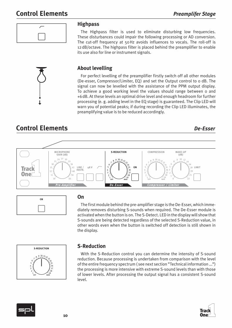
HighpassThe Highpass filter is used to eliminate disturbing low frequencies.
These disturbances could impair the following processing or AD conversion. The cut-off frequency at 50 Hz avoids influences to vocals. The roll-off is 12 dB/octave. The highpass filter is placed behind the preamplifier to enable its use also for line or instrument signals.
About levellingFor perfect levelling of the preamplifier firstly switch off all other modules
(De-esser, Compressor/Limiter, EQ) and set the Output control to 0 dB. The signal can now be levelled with the assistance of the PPM output display. To achieve a good working level the values should range between 0 and +6 dB. At these levels an optimal drive level and enough headroom for further processing (e. g. adding level in the EQ stage) is guaranteed. The Clip LED will warn you of potential peaks; if during recording the Clip LED illuminates, the preamplifying value is to be reduced accordingly.
OnThe first module behind the pre-amplifier stage is the De-Esser, which imme-
diately removes disturbing S-sounds when required. The De-Esser module is activated when the button is on. The S-Detect. LED in the display will show that S-sounds are being detected regardless of the selected S-Reduction value, in other words even when the button is switched off detection is still shown in the display.
S-ReductionWith the S-Reduction control you can determine the intensity of S-sound
reduction. Because processing is undertaken from comparison with the level of the entire frequency spectrum ( see next section ”Technical information ...”) the processing is more intensive with extreme S-sound levels than with those of lower levels. After processing the output signal has a consistent S-sound level.
Control Elements Preamplifer Stage
Control Elements De-Esser

11
Technical information regarding the De-EsserIn contrast to common de-essers that influence a frequency band of about
2 octaves with compressor techniques the Auto-Dynamic De-Esser utilizes filters that process only the reducible ”S-frequencies” but do not interfere with the remainder of the spectrum. The S-frequencies that lie in the unple-asant range are automatically recognized, the phase is inverted and mixed with the original signal. In this manner the disturbing frequency is quenched and the hissing noise reduced. This method of operation has distinct advan-tages because it is unobtrusive and helps retain the original tonal quality.
Compressor-typical side effects such as lisping or nasal tones do not occur. Finally its operation is as simple as pulling on the hand brake.
The reduction is accomplished by comparing the entire level with the indivi-dual S-sounds: the De-Esser functions only when the S-noise level exceeds the average level of the entire frequency spectrum. This means for example that original S-sounds with a determinate S-portion are not processed whereas those that are too loud, or do not effectively contribute to the sound, are reduced – the character of the voice remains unchanged.
A further specialty is the integrated auto-threshold-function which makes processing independent of the input level. Even when the speaker or singer does not maintain a constant distance to the microphone, processing is reta-ined at the pre-set S-reduction value. Conventional systems are dependent on the input level and work more intensively as the distance to the microphone is reduced.
OnThe On button activates the Compressor/Limiter module. At the same time
the Gain Reduction display shows the processing intensity (see section ”Gain Reduction” on page 16).
LimiterThe Limit button switches the Compressor to limiter mode. The Compression
control serves the purpose of controlling the threshold. The Limiter does not function as a peak limiter, in other words there is no guarantee that all peaks are intercepted. It is therefore advisable when modulating a subsequent unit that a headroom of 2 to 4 dB remains. Peak limiters have a system-based disadvantage in that audible distortions are heard considerably sooner, which
De-Esser Control Elements
Compressor/Limiter Control Elements
iinfo

12
is particularly undesirable for live recording – a „destroyed“ signal must be recorded again, but a clean signal can still be processed, if for example further compression/limiting is needed.
CompressionThe Compression control sets the intensity of compression. Turning the
control clockwise increases compression. The working area spans between + 20 dB (counter clockwise limit) and -50 dB (clockwise limit).
The compressor applies the so-called ”soft-knee” characteristic, which means that quiet passages are processed at a lower compression ratio than louder passages. At maximal compression it operates with a ratio of 1:3 – very effective dynamic limits are achievable when inconspicuous characteri-stics are to be processed. The exact development of the compressor curve is portrayed in the diagram 1 on page 18. When setting the compression rate the Gain Reduction display in the display field is of great assistance. The effect on the selected compression rate is scaled in 1.5 dB steps. Depending on signal source and dynamic structure the reduction values should lie between 4 and 8 dB to restrict higher peaks and to optimize the operation of the subsequent recording system.
IMPORTANT: Make sure that the Comp. Link switch on the rear panel is set to MASTER, otherwise the compressor will not work. Only if two devices are operated in master/slave mode, this switch may be set to SLAVE on one unit. Please also refer to „Connections“ on page 8.
Make UpWith the Make Up control the level reduction caused by compression or limi-
ting can be restored. With assistance of the Gain Reduction display in the display field setting the Make Up control is very easy: If the maximal reduction value caused by the loudest tone amounts to -9 dB, for instance, the Make Up control is also to be set to the value +9 dB. If the Compressor/Limiter is now switched off the achieved gain in loudness will be audible.
Technical Information regarding the Compressor/LimiterIn the Compressor/Limiter section of the Track One the parameters for the
time constants (Attack and Release) are set automatically and adapt them-selves to the changing conditions of the input signal, far better than can ever be achieved by manual adjustments. The transient and final oscillation beha-vior of voices and instruments are constantly changing and at times are so erratic that a manual control will only achieve good average values, which at critical moments can produce disadvantageous effects (distortion and artif-acts).
If for example the compressor has to react very quickly to harsh P or T noises it must also be capable of reacting slowly to softer tones – otherwise distor-tion occurs. Accordingly the Track One Compressor/Limiter regulates the level of large fluctuations faster than smaller ones; tones of longer duration are automatically processed with a longer attack time to prevent distortions.
Control Elements Compressor/Limiter
iinfo

13
Even the control of the release time is dependent on the input signal. Fast and large level fluctuations are correspondingly processed with shorter time constants than minor fluctuations in order to limit the distortion of the audio signal as far as possible. Overall this technique provides the optimal solution between fast, unobtrusive control response and the least distortion of the audio signal. The result is a natural and transparent sound impression.
The Compressor/Limiter characteristics are portrayed on page 18.
OnThe On button inserts the Equalizer module into the signal path.
Low BandThe center frequency of the half-parametric bass filter is set with the Low
Band control. The adjustable frequency range lies between 30 Hz and 720 Hz so that this filter covers a range of about 4.5 octaves, allowing it to be used from the deepest bass to the lower mid range. This together with the Mid-Hi filter ensures that the entire frequency spectrum is covered.
Cut/Boost (Low)The Cut/Boost control determines the boost or cut of the Low Band filter;
the maximum values lie between +/- 14 dB. The Low Band filter also operates to the proportional-Q-principle, in other words the bandwidth is dependent on the selected boost or cut. With the Low Band filter the factor with which the relationship of the boost or cut values, in relation to the bandwidth, is determined lies somewhat higher than with the Mid-Hi filter. The bandwidth is therefore marginally narrower at maximum boost than with the Mid-Hi filter. The exact curve of the Low Band filter is shown in diagram 2 on page 18.
The Low Band filter can be applied in many ways. Examples are; to accen-tuate the fundamental sound of a voice, to cut ”boom frequencies” and for placement of bass emphasized instruments such as bass guitar, bass drums- or synthesizers during recording or subsequently when mixing etc.
Control ElementsCompressor/Limiter
Control ElementsEqualizer

14
Mid-Hi BandThe center frequency of the semi-parametric mid high frequency filter is set
with the Mid-Hi Band control. The frequency range can be set between 650 Hz and 13.7 kHz so that this filter covers a range of 4.5 octaves and can be equally employed in the lower mid as well as the high range.
Cut/Boost (Mid-Hi)The Cut/Boost control determines the boost, or cut of the Mid-Hi filter; the
maximum values lie between +/- 12 dB. The Mid-Hi filter utilizes the propor-tional-Q-principle. In other words the bandwidth is dependent on the selected boost or cut. The higher the boost or cut values are set, so the bandwidth becomes narrower; by low boost or cut values the bandwidth increases (the exact curve of the Mid-Hi filter can be seen in diagram 3 on page 19). This filter characteristic permits a musically more sensible processing of the frequency spectrum than with constant-Q filters: if a more thorough setting has been chosen this will lead to far preciser definition of the frequency range to be processed. This in turn minimizes influences from adjacent ranges.
This filter construction permits the complete scope, from selective removal of accentuated frequencies through to character giving accentuations of an instrument, to be effectively and quickly covered.
Air BandThe high frequency filter in the equalizer module is described as the ”Air
Band” and serves the processing of the frequency range of 2 and 20 kHz. A coil-capacitor-filter with so called bell characteristics and a center frequency of 17.5 kHz comes into operation here. At this frequency the maximum possible accentuation is +10 dB, the maximum possible damping is -10 dB. The charac-teristics of the Air Band filter are shown in diagram 4 on page 19.
The ”soft” and natural tonal property, characteristic of the coil-capacitor filter, lends itself extremely well to provide clarity to vocals in the upper frequency range thereby improving their presence. On the other hand harsh sounds can be lent a more pleasant sound characteristic through damping.
Recommendation on frequency settingsTo find the frequency which is to be processed as quickly and accurately
as possible the Cut/Boost control should firstly be adjusted to the maximum position. Subsequently the relevant frequency should be sought. Following this the required boost or cut can be set with the Cut/Boost control. Because the filter at maximum setting works with the smallest bandwidth the frequen-cies can be heard most distinctly at this setting, making them easier to locate.
Control Elements Equalizer
15
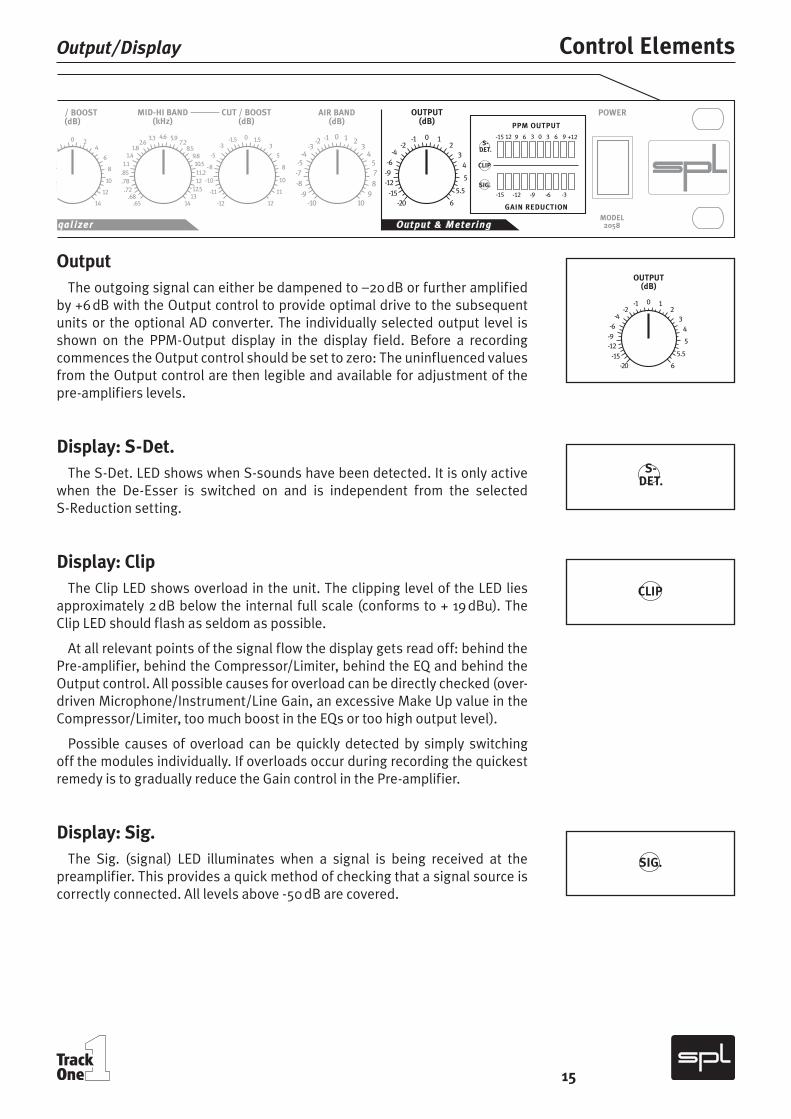
OutputThe outgoing signal can either be dampened to –20 dB or further amplified
by +6 dB with the Output control to provide optimal drive to the subsequent units or the optional AD converter. The individually selected output level is shown on the PPM-Output display in the display field. Before a recording commences the Output control should be set to zero: The uninfluenced values from the Output control are then legible and available for adjustment of the pre-amplifiers levels.
Display: S-Det.The S-Det. LED shows when S-sounds have been detected. It is only active
when the De-Esser is switched on and is independent from the selected S-Reduction setting.
Display: ClipThe Clip LED shows overload in the unit. The clipping level of the LED lies
approximately 2 dB below the internal full scale (conforms to + 19 dBu). The Clip LED should flash as seldom as possible.
At all relevant points of the signal flow the display gets read off: behind the Pre-amplifier, behind the Compressor/Limiter, behind the EQ and behind the Output control. All possible causes for overload can be directly checked (over-driven Microphone/Instrument/Line Gain, an excessive Make Up value in the Compressor/Limiter, too much boost in the EQs or too high output level).
Possible causes of overload can be quickly detected by simply switching off the modules individually. If overloads occur during recording the quickest remedy is to gradually reduce the Gain control in the Pre-amplifier.
Display: Sig.The Sig. (signal) LED illuminates when a signal is being received at the
preamplifier. This provides a quick method of checking that a signal source is correctly connected. All levels above -50 dB are covered.
Output/Display Control Elements

16
Display: PPM OutputThe PPM Output display shows the peak reading of the output level (cali-
brated to 0 dB) and is present at the analog outputs on the rear of the unit. This display also serves to the pre-amplifying Gain. The value ”+12 dBu” marked on the right side represents the maximum level of the optional AD/DA converter which should not be exceeded. (Further information is given in the directions to the AD/DA converter).
Although the values of the PPM Output display only cover up to + 12 dB sufficient headroom remains internally (approximately 6 dB) so that the output value can exceed this limit without causing clipping. The range of optimal noise performance lies between 0 and + 9 dB.
Display: Gain ReductionThe Gain Reduction display provides information about the processing being
undertaken with the Compressor/Limiter or the Noise Gate. The level change, perhaps caused by compression, are scaled in 1.5 dB steps. The display is acti-vated when the Compressor/Limiter module is switched on.
Built around a torroidal transformer, the power supply allows for a minimal electromagnetic field with no hum or mechanical noise. The power supply‘s output side is filtered by an RC circuit to extract noise and hums caused by your power service. 6000 µf capacitors smooth out the positive and negative half waves.
The phantom power is derived with a precise current regulator to provide a clean phantom power of 48 volts. Our high quality 0.1 % / 6,81 kOhm resistors ensure the pristine quality of the phantom power supply.
The supply voltage can be set to 230 V/50 Hz or 115 V/60 Hz. Check your country‘s power requirements for the appropriate setting. An AC power cord is included to feed the IEC-spec, 3-prong connector. Transformer, AC cord and IEC-receptacle are VDE, UL and CSA approved. The main fuse is rated at 315 mA for 230 v and 630 mA for 115 v.
Chassis ground and AC ground can be physically disconnected by the “Ground Lift” switch (Gnd Lift). This helps to eliminate hums.
Control Elements Output/Display
Power Supply

17
Microphone InputFrequency response: 10 Hz-200 kHz(200 kHz = -3 dB)
Common mode rejection: 1 kHz: -80 dB / 10 kHz: -68 dB (at -20 dBu)
THD & NAmplification: A-weighted:20 dB -97,5 dBu40 dB -91,0 dBu65 dB -69,6 dBu
Dynamic response: 115dB
Instrument InputFrequency response: 10 Hz-180 kHz(180 kHz = -3 dB)
THD & NAmplification: A-weighted:7 dB -98,4 dBu20 dB -95,8 dBu42 dB -77,2 dBu
Input impedance Line: 12kOhm / Instr.: 1 MOhm
Max. input level Line: +25 dBu / Instr.: +13 dBu
Dynamic response: 115 dB
OutputsMax. output level XLR/jack: +20 dBu
Output impedance: ‹ 50 Ohm
Power supplyToroidal transformer: 15 VA
Fuses: 315 mA (230 V/50 Hz) 630 mA (115 V/60 Hz)
DimensionsStand.-EIA-19 inch/1 U housing: 482 x 44 x 210 mm
Weight: 3.1 kg
Specifications

18
Measurements Compressor/Limiter, Low Band
Diagram 1 portrays the characteristics of the compressor and limiter
Line A displays the relation between input and output
Line B shows the curve characteristics of the com-pressor
Line C protrays the limiter‘s curve characteristics
A
C
B
Diagram 2 shows the curves of the Low Band filter
Various settings around 200 Hz

19
Mid-Hi Band, Air Band Measurements
Diagram 4 portrays various cut and boost settings of the Air Band filter
Diagram 3 displays various cut and boost settings of the Mid-Hi filter at around 1,8 kHz

20
Warranty
All SPL products come with a two-year manufacturer’s guarantee against defects in material or assembly from the date of purchase.
End users are supported in the two-year guarantee through their distributor or dealer. In such cases, please contact your dealer for full guarantee condi-tions and service.
Direct SPL product support requires product registration. Please fill out the guarantee card enclosed in the package legibly in printed letters and send it directly to SPL. Or use the online registration form that may be reached at www.soundperformancelab.com (international clients) or www.spl-usa.com (US clients).