Embed Size (px)
Citation preview

METAL ROOFING INSTALLATION
GUIDE
CF PANELMANUAL

TABLE OF CONTENTS
2
Preparation Requirements and Recommendations 3
Safety Considerations 4
Care and Handling of Mueller Sheet Metal 5
Storage & Tools Required 6
Standard Parts 7
Product Description 10
Standard Fastener Locations at Panel 11
Recommended Screw Placement Table 12
Oil Canning Reduction Trim Installation 13
Detail Locator 14
Beginning the ProjectStandard Eave Trim Installation 15
Standard Eave Trim Installation with Gutter 16
Standard Adjustable Gable & Strip Installation 17
Starting and Ending Panel Installation 18
High Side Residential Eave Trim Installation 19
Valley Panel and Trim Installation 20
Standard Ridge Roll and Hip Installation 21
Endwall to Roof Flashing Installation 22
Sidewall Flashing Installation 23
Roof Pitch Change Installation 24
Standard Panel Endlap 25
Chimney Flashing - Uphill and Downhill 26
Chimney Flashing - Side and Vent 27
Contact Information 28

This detail & installation manual has been provided to serve as a basic guideline for installing the Mueller CF panel roof system. This manual should be used in conjunction with the erection drawings to help ensure proper installation of this roof system. In case of discrepancies, the erection drawings will govern over this installation guide.
It is the customer’s responsibility to ensure that a competent and experienced erection crew is chosen for the installation of this roof system. It is also the customer’s responsibility to ensure the erection crew understands and follows this installation manual and the erection drawings.
Mueller, Inc. is not responsible for any problems or defects caused by improper erection techniques. Any questions in regards to clarifying the intent of this manual or the erection drawings should be directed to Mueller’s customer service department at the address and phone number shown on the back cover.
Warning: CF Panels should not be installed on a roof that is less than a 3:12 pitch. When this panel is installed on pitches less than 3:12, heavy rainfall may lead to water accumulation and possible leaks.
Note: It is important that the roof be properly prepared before installation begins. Decking Mueller, Inc. recommends our metal roofing systems be installed over CDX plywood wooden roof decking with a minimum thickness of 15/32”. Note: If using treated lumber, special corrosive resistant screws are required. Ask your sales representative for more information.
Stripping The removal of existing roofing and the associated fasteners is generally necessary. This does not damage, and typically improves, the structural capacity of wood decks. During removal, many shingle fasteners may remain embedded in the deck. These fasteners can be pulled out or hammered flush with the deck.
RepairsDeteriorated areas should be removed and replaced with material to closely match the existing thickness. The deck should be sound and smooth, with fasteners flush with the surface, prior to the installation of the metal roof. New wood decking, whether boards, planks, CDX plywood, or equal, should be the same thickness and have similar strength characteristics and span ratings to that of the area being replaced. Deck fasteners that have backed out should have a new fastener installed adjacent to it and the existing fastener should be removed. Loose or lifted boards, planks, plywood, and corners should have additional fasteners installed to secure the existing deck in place.
Holes in wood decks that are 10” wide or less can be covered with 20-gauge steel. This steel plate should be galvanized and must overlap the wood roof deck 4 inches minimum and be secured with fasteners 4 inches on center.
Fascia boards should be straight, level and in good condition. Any rotted or deteriorated boards should be replaced. All roof framing and decking abnormalities will be transferred to the new metal roof if not corrected before sheeting begins.
UnderlaymentNew underlayment must be immediately installed over prepared roof decking. Mueller recommends Titanium or a minimum 30# felt. This underlayment should be installed with a minimum of a 2” side lap and a 6” end lap. Underlayment temporar-ily protects the roof decking against water penetration. It should be installed using galvanized tin caps (not plastic caps). The underlayment should be fastened to the deck with galvanized roofing nails with tin caps 12” on center in the field and 6” on center at the sidelaps.
Flashing Re-roofing projects incorporate metal flashing and metal counter-flashing. Some counter-flashing are embedded, such as a masonry wall, or are installed behind existing siding. This metal, if not deteriorated, may be reused. The existing metal can be cut, leaving approximately a minimum of 2” of flashing exposed, and new counter-flashing can be fastened to the backside of the existing metal. Counter-flashing must be slightly higher than the top of the rib on the sheets to be installed.
3
PREPARATION REQUIREMENTS & RECOMMENDATIONS

As with all major construction projects, safety should be a primary concern. The erector or contractor should be sure
that all OSHA safety rules are followed and that job safety is strictly adhered to.
The following safety equipment is highly recommended when installing metal roofing:
1. Safety rope and harness
2. Hand protection
3. Eye protection
4. Hearing protection
5. Soft rubber soled shoes
Metal roofing presents several specific safety issues:
1. Metal roofing is extremely slick and does not provide firm footing. Extreme care should be taken when:
A. Working on roofs with very steep pitches.
B. Working on roofs when moisture is present.
C. Working on roofs when high wind is a factor.
D. Working with long panels.
2. Metal edges are very sharp and should be handled with care.
3. Care should be used when lifting panels due to their weight.
4. Always check for overhead electrical lines and exercise care not to have metal sheets come in contact with them.
5. All electrical tools should be inspected regularly for damaged cases or frayed electric cords. Extension cords should
be inspected for damaged or frayed insulation. Tools which do not meet good safety standards should not be used.
CAUTION: Care should be taken when cutting sheets. Eye and hearing protection are important.
Panels may be slick!Because of the demands of the manufacturing process, oil has been applied to the coil stock to protect the coil, as well as
the finished panel during manufacturing, shipping and storage. Metal panels must be wiped clean prior to panel installation.
NOTE: Always wear rubber soled work boots. When on the roof, use OSHA approved protection devices such as safety lines,
safety nets or catch platforms.
Unsecured Panels May Slip If Stepped On!Never step on a single unsecured roof panel, or a stack of roof panels laying unattached on the roof. Secure each end of
the panel with clamps or appropriate fasteners and place walkboards of adequate size and strength in the flat of any
panels not fully secured to the roof and supported by panels on each side. Walkboards should run the full length of the
panel and be fastened together by drilling a hole near the end of each board and tied with rope to the next board. Cut a
groove in the bottom of each board so the board will lie flat and not tip back and forth because of the rope.
4
SAFETY CONSIDERATIONS

Delivery: Mueller takes every precaution to ensure that material is delivered to the customer damage-free and fully protected
from the elements during shipment. When the material is delivered to the customer it then becomes the customer’s responsibil-
ity to protect the material from the elements, possible theft, and other damage. The following guidelines are recommended:
HANDLING: Proper care is required in unloading and handling panel bundles in order to prevent damage.
1. Bundles should remain banded (if possible) during the unloading process. Bundles should never be lifted by the banding material.
2. Lift each bundle as close as possible to its center of gravity.
3. If the bundles are to be lifted with a crane, use a spreader bar of appropriate length and nylon band slings (do not use wire rope slings as they will damage the material).
4. Depending on the panel length, some bundles may be lifted by a forklift. When using a forklift, the forks should be spread to their maximum spacing, and the load centered on the forks. Sheets over 25’ long require two forklifts.
5. After panel bundles are opened, individual sheets must be handled carefully to prevent panel buckling or damage to the panel coating. When removing a sheet from a bundle it should be rolled off the bundle to prevent scratching of the next sheet. Never drag or slide one sheet over another sheet. Sheets should not be picked up by the ends. Instead, lift the sheet along its longitudinal edge and carry in a vertical position. For sheets over 10’ long, two or more people may be required to carry the sheet.
Wall and Roof PanelsMueller’s wall and roof panels, including color coated, galvalume and galvanized, provide excellent service under widely varied conditions. All unloading and erection personnel should fully understand that these panels are quality merchandise which merit cautious care in handling.
Under no circumstances should panels be handled roughly. Packages of sheets should be lifted off the truck with extreme care taken to ensure that no damage occurs to ends of the sheets or to side ribs. The packages should be stored off the ground sufficiently high to allow air circulation underneath the packages. This avoids ground moisture and deters people from walking on the packages. One end of the package should always be elevated to encourage drainage in case of rain.
All stacked metal panels are subject, to some degree, to localized discoloration or stain when water is trapped between their closely nested surfaces. Mueller, Inc. exercises extreme caution during fabrication and shipping operations to ensure that all panel stock is kept dry. However, due to climatic conditions, water formed by condensation of humid air can become trapped between stacked sheets. Water can also be trapped between the stacked sheets when exposed to rain. This discoloration caused by trapped moisture is often called “wet storage stain.”
The stain is usually superficial and has little effect on the appearance or service life of the panels as long as it is not permitted to remain on the panels. However, moisture in contact with the surface of the panels over an extended period can severely attack the finish and reduce the effective service life. Therefore, it is imperative that all panels be inspected for moisture upon receipt of the order. If moisture is present, dry the panels at once and store in a dry, warm place.
5
CARE AND HANDLING OF MUELLER SHEET METAL

6
STORAGEStorage: It is recommended that sheets be kept covered
and out of the elements if at all possible. If sheets are to
be stored outside, the following precautions should be
observed:
1. The storage area should be reasonably level, and located so as to minimize handling.
2. When stored on bare ground, place plastic ground cover under the bundles to minimize condensation on the sheets from ground moisture.
3. Store bundles at least 12 inches above ground level
to allow air circulation beneath the bundle, and to
prevent damage from rising water.
4. Elevate one end of each bundle slightly to permit
runoff of moisture from the top of the bundle or
from between sheets. A waterproof cover should be
placed loosely over the bundles to allow for air
circulation under the cover.
5. Inspect stored bundles daily and repair any tears
or punctures in the waterproof cover.
6. Re-cover opened bundles at the end of each work
day to prevent subsequent moisture damage.
Checking order at time of delivery:Check each order carefully, as it is unloaded. Report any
obvious damage or shortages to the carrier immediately.
If damage or shortages are noted after delivery (at time
of unpacking) notify your Mueller representative imme-
diately. Have invoice numbers and detailed descriptions
of the damage or shortage available. These procedures
are for your protection. A shortage or damage discovered
later can be caused by theft, misplacement, mishandling
or other causes and is not the responsibility of Mueller, Inc.
Underlayment: The underlayment should be one layer
of Titanium or 30# felt. The Titanium should have a
2” side lap and a 6” end lap. The underlayment should
be fastened to the deck with galvanized roofing nails
with tin caps 12” on center in the field and 6” on
center at the sidelaps.
TOOLS REQUIREDThe following list of tools is recommended when installing metal roofing:
1. Aviation snips - left, right, straight 6. Square 11. Broom 16. Fire extinguisher
2. Screw gun 2500 RPM with appropriate nut drivers 7. Straight edge 12. Extension cords 17. Saw horses
3. Tape measure 8. Chalk line 13. Ladder 18. First aid kit
4. Caulking gun 9. Vise grips 14. Hammer 19. Tarp
5. Safety equipment: goggles, hard hat, 10. Gloves 15. Drill bits 20. Electric shear or nibbler and soft rubber soled shoes
CAUTION: Whenever using any type of power equipment, it is important to follow the manufacturer’s recommendation for use. Always be aware of the danger involved when using electric or air powered equipment.
Never Install Material if the Quality is in Question!

7
Details are subject to change without prior notice.
7
STANDARD PARTS
Details are subject to change without prior notice.
Note: If using treated lumber, special corrosive resistant screws are required. Ask your sales representative for more information.
"

STANDARD PARTS
8

9
STANDARD PARTS
#0324 12" or 24"
10
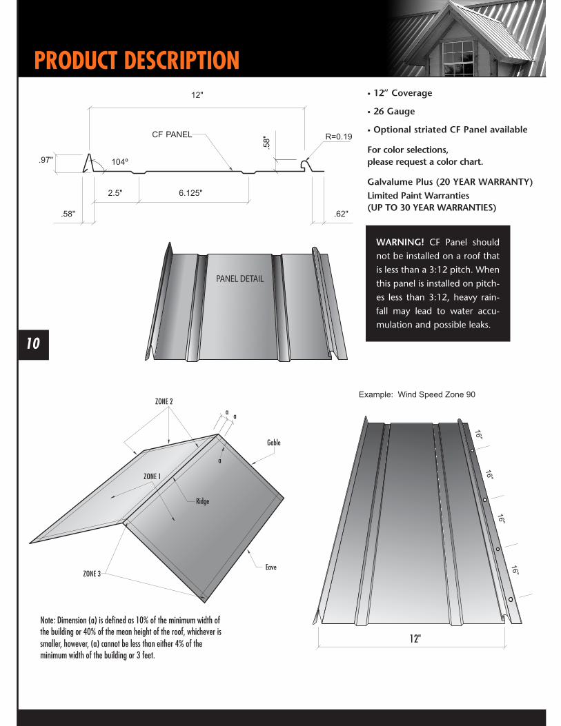
PRODUCT DESCRIPTION• 12” Coverage
• 26 Gauge
• Optional striated CF Panel available
For color selections, please request a color chart.
Galvalume Plus (20 YEAR WARRANTY)Limited Paint Warranties(UP TO 30 YEAR WARRANTIES)
WARNING! CF Panel should
not be installed on a roof that
is less than a 3:12 pitch. When
this panel is installed on pitch-
es less than 3:12, heavy rain-
fall may lead to water accu-
mulation and possible leaks.

11
Details are subject to change without prior notice.Details are subject to change without prior notice.
11
STANDARD FASTENER LOCATIONS AT PANEL
WARNING! Mueller trim comes
with a protective film coating
to aid in the prevention of scuff-
ing. Do not allow this film to be
exposed to the sun. Exposure will
bond the film to the metal mak-
ing removal difficult.
ATTACHMENT TO 1 X 4 WOOD PURLIN
TYPE 1: FASTENER LOCATION
TYPE 2: FASTENER LOCATION
TYPE 2: FASTENER LOCATION
NOTE: To comply with Texas
Windstorm Certification Testing,
#12x11 SDT Type A screws
must be used in place of the #9
Woodgrip screws.

RECOMMENDED SCREW PLACEMENT TABLE
Details are subject to change without prior notice.Note: If using treated lumber, special corrosive resistant screws are required. Ask your sales representative for more information.
Zone
FASTENER SUBSTRATE90
ON CENTERSPACING
100
ON CENTERSPACING
110
ON CENTERSPACING
120
ON CENTERSPACING
130
ON CENTERSPACING
140
ON CENTERSPACING
Zone 1
#10-12 X 1” 15/32” CDX
19/32” CDX
7/16” OSB
1x4 Wood Purlins
20”
20”
15”
Type 1, 20”
20”
20”
15”
Type 1, 20”
20”
20”
15”
Type 1, 20”
20”
20”
15”
Type 1, 20”
20”
20”
N/A
Type 1, 20”
N/A
N/A
N/A
Type 1, 10”
Zone 2
#10-12 X 1” 15/32” CDX
19/32” CDX
7/16” OSB
1x4 Wood Purlins
20”
20”
15”
Type 1, 20”
20”
20”
15”
Type 1, 20”
10”
20”
15”
Type 2, 20”
10”
10”
10”
Type 2, 10”
10”
10”
N/A
Type 2, 10”
N/A
N/A
N/A
Type 2, 1 0”
Zone 3
#10-12 X 1” 15/32” CDX
19/32” CDX
7/16” OSB
1x4 Wood Purlins
10”
20”
15”
Type 2, 10”
10”
10”
10”
Type 2, 10”
10”
10”
10”
Type 2, 10”
10”
10”
10”
Type 2, 10”
10”
10”
N/A
Type 2, 10”
N/A
N/A
N/A
Type 2, 10”
Zone
FASTENER SUBSTRATE90
ON CENTERSPACING
100
ON CENTERSPACING
110
ON CENTERSPACING
120
ON CENTERSPACING
130
ON CENTERSPACING
140
ON CENTERSPACING
Zone 1
#10-12 X 1” 15/32” CDX
19/32” CDX
7/16” OSB
1x4 Wood Purlins
20”
25”
15”
Type 1, 20”
20”
25”
15”
Type 1, 20”
20”
25”
15”
Type 1, 20”
20”
25”
15”
Type 1, 20”
20”
25”
15”
Type 1, 20”
10”
25”
15”
Type 2, 10”
Zone 2
#10-12 X 1” 15/32” CDX
19/32” CDX
7/16” OSB
1x4 Wood Purlins
20”
25”
15”
Type 1, 20”
20”
25”
15”
Type 1, 20”
20”
25”
15”
Type 1, 20”
20”
25”
15”
Type 1, 20”
10”
25”
15”
Type 2, 10”
10”
25”
10”
Type 2, 10”
Zone 3
#10-12 X 1”
15/32” CDX
19/32” CDX
7/16” OSB
1x4 Wood Purlins
20”
25”
15”
Type 1, 20”
20”
25”
15”
Type 1, 20”
20”
25”
15”
Type 1, 20”
20”
25”
15”
Type 1, 20”
10”
25”
15”
Type 2, 10”
10”
25”
10”
Type 2, 10”
WIND SPEED ZONE
FASTENING SCHEDULE SPACING ALONG PANEL NAIL STRIPWith < 30’-0” mean roof height - 3:12 to 6:12 pitch for 90-140 mph wind speeds based on ASCE 7-93
WIND SPEED ZONE
FASTENING SCHEDULE SPACING ALONG PANEL NAIL STRIPWith < 30’-0” mean roof height - 7:12 to 12:12 pitch for 90-140 mph wind speeds based on ASCE 7-93
CF PANEL

13
Details are subject to change without prior notice.
INSTALLATION
12"
Oil Canning Reduction Trim on AP Panel
Oil Canning Reduction Trim on CF Panel
24"
OIL CANNINGWhat is Oil Canning?Oil canning is described as a wavy appearance often occurring in the flat areas of formed metal products, such as metal roofs. The structural integrity of the metal is not affected by oil canning – it’s simply an aesthetic issue. The term oil canning is an industry standard used to describe this occurrence and is not a reason for rejection.
Things to Expect• If the deck is bowed up or has a belly, the new
sheets will oil can.
• High temperatures are often a factor when waviness occurs. Once it gets cooler, the effect will likely diminish.
• Changes in light – including overcast days, shade, and intense sunlight – can affect the appearance of oil canning. Oil canning will seem less prominent in the shade but will be more noticeable in brighter light.
• The color of the metal panel can also affect the appearance of oil canning. For example, oil canning is more evident on galvalume, copper or other metallic colors.
1. Prior to applying the panel, the oil canning reduction trim should be positioned on the decking so that the trim is centered in the flat section between the ribs of the panel when it is applied.
2. The trim should be positioned to start 3’ from one end and stop 3’ from the other end of each panel.
3. The trim should be held in place by screwing through the trim into the decking at each end of the trim piece.
4. Reduction trim sections are 12’. These should be field cut to length as needed. All joints should be butted not lapped. Drops need to be utilized.
The purpose of this application is to reduce the effect of oil canning on the Mueller CF panels. It will not completely eliminate oil canning on these panels. The strip must be applied down the flat section of the panel.
13
IMPORTANT INFORMATION
Details are subject to change without prior notice.
0.85”
0.35”0.35”0.50”

14
Details are subject to change without prior notice.
DETAIL LOCATOR
1
4
7
28
35
9
6
DETAIL SECTION Page
1 Eave .............................................15
2 Gable ...........................................17
3 Valley ...........................................20
4 Ridge ..........................................21
5 Hip ...............................................21
6 Endwall to Roof Transition .........22
7 Sidewall Flashing .........................23
8 Pitch Change ..............................24
9 Chimney Flashing ........................26

15
Details are subject to change without prior notice.
15
BEGINNING THE PROJECT
Details are subject to change without prior notice.
1. Install the eave trim by sliding it underneath the underlayment and securing it to the roof surface with wafer head screws on 5’ centers.
2. There are no screws or nails to be placed in the exposed fascia of the trim.
3. At the corners, cut the eave trim 1 1/2” long and prepare the ends with tabs to receive the gable trim.
NOTE: Alternate trim profiles are acceptable using the screw pattern shown.
OPTION: The overhang illustrated below may be increased to extend up to 4” past the eave trim.
STANDARD EAVE TRIM INSTALLATION

16
STANDARD EAVE TRIM INSTALLATION WITH GUTTER
Details are subject to change without prior notice.
1. Install the eave trim to the substrate with wafer head fasteners at 5’ O.C.
2. Position the roof panel so that the down slope end matches the dimension called for on the erection drawings.
3. Attach the roof panels at the eave with (3) #9 x 1” woodgrip screws - (3) per panel.
4. Attach the gutter to the panel and the eave trim with #14 x 7/8” lapteks @ 24” O.C.
5. Install the gutter strap at alternate 24” with #14 x 7/8” lapteks on the sheet end of strap, and stitch screws, pop rivets, or lap screws on gutter end of the strap.
NOTE: Alternate trim profiles are acceptable using the screw pattern shown.
NOTE: To comply with Texas
Windstorm Certification Testing,
#12x11 SDT Type A screws
must be used in place of the #9
Woodgrip screws.
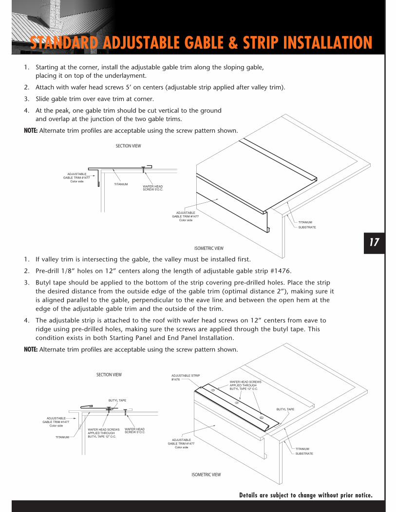
1. Starting at the corner, install the adjustable gable trim along the sloping gable, placing it on top of the underlayment.
2. Attach with wafer head screws 5’ on centers (adjustable strip applied after valley trim).
3. Slide gable trim over eave trim at corner.
4. At the peak, one gable trim should be cut vertical to the ground and overlap at the junction of the two gable trims.
NOTE: Alternate trim profiles are acceptable using the screw pattern shown.
17
STANDARD ADJUSTABLE GABLE & STRIP INSTALLATION
1. If valley trim is intersecting the gable, the valley must be installed first.
2. Pre-drill 1/8” holes on 12” centers along the length of adjustable gable strip #1476.
3. Butyl tape should be applied to the bottom of the strip covering pre-drilled holes. Place the strip the desired distance from the outside edge of the gable trim (optimal distance 2”), making sure it is aligned parallel to the gable, perpendicular to the eave line and between the open hem at the edge of the adjustable gable trim and the outside of the trim.
4. The adjustable strip is attached to the roof with wafer head screws on 12” centers from eave to ridge using pre-drilled holes, making sure the screws are applied through the butyl tape. This condition exists in both Starting Panel and End Panel Installation.
NOTE: Alternate trim profiles are acceptable using the screw pattern shown.
Details are subject to change without prior notice.

18
Details are subject to change without prior notice.
18
STARTING AND ENDING PANEL INSTALLATION
Details are subject to change without prior notice.
Starting Panel1. Apply adjustable strip as previously instructed.
2. Remove the overlap rib of the panel, making a straight cut the length of the panel.
3. Apply butyl tape continuously down the length of the adjustable strip, covering the wafer head screw.
4. Insert the cut edge of the panel into the strip, making sure the panel is seated fully into the strip.
5. Attach the underlap side to the roof with wafer head screws on the required centers.
NOTE: Alternate trim profiles are acceptable using the screw pattern shown.
Ending Panel1. Remove the underlap rib of the panel at a point that is inside the adjustment portion of the gable trim, making a straight cut the length of the panel (optimal 2” from gable edge).
2. Apply adjustable strip as previously instructed.
3. Test apply the panel to assure proper fit.
4. Apply butyl tape and insert last panel into strip, making appropriate panel lap.
NOTE: Alternate trim profiles are acceptable using the screw pattern shown.

19
HIGH SIDE RESIDENTIAL EAVE TRIM INSTALLATION
Details are subject to change without prior notice.
1. Attach the high side trim (#0803) to the fascia with woodgrip screws on 5’ centers. Make sure the 6” side of the trim is on the rooftop with the receiver hem resting on the highs.
2. Cap the ends of the trim by cutting and folding a tab that attaches to the gable trim. The hem must be removed before a fold is made. Capping is usually easier to do before the trim is installed. If done after the trim is installed, be sure and leave 6” of the trim overhanging to allow enough material for cut and folds.
3. Slide the 5/8” lip of the metal closure into the receiver hem of the eave trim and position the closure on the sheet.
4. Attach with one woodgrip screw, centered between each rib, through the hem of the ridge roll and metal closure, into the decking. Care must be taken not to over-tighten the screws, as this will distort the trim and closures. The screw hole can be pre-drilled, if desired.
5. All end laps should be at least 4”. Remove 4” of the hem on the overlapping piece and secure it to the overlapped piece with caulk and stitch screws.
NOTE: Alternate trim profiles are acceptable using the screw pattern shown.
NOTE: To comply with Texas
Windstorm Certification Testing,
#12x11 SDT Type A screws
must be used in place of the #9
Woodgrip screws.

20
VALLEY PANEL AND TRIM INSTALLATION
Details are subject to change without prior notice.
1. Start at the low end, trim and place the valley flashing. The valley end should overhang the eave trim 1”.
2. If there is an end lap required in the valley pieces, caulk and lap at least 8”.
3. Use wafer head screws on 5’ centers to secure the valley in place along the outside edge.
4. Hem the edges of the valley over the eave trim, after trimming the center “V” back 1” to align with the edge of the eave. Leave a tab to bend and cover the exposed opening of the center “V”.
5. Place butyl tape on the upper surface of the valley 6” up slope from the “V” of the valley trim, before applying intersecting panels.
6. Field cut the panels that intersect the valley holding the end of the panel 4” back from the “V” of the valley trim and parallel to the “V” of the valley.
7. Attach panel at valley using eave screw requirements for panel being installed.
NOTE: Alternate trim profiles are acceptable using the screw pattern shown.
NOTE: To comply with Texas
Windstorm Certification Testing,
#12x11 SDT Type A screws
must be used in place of the #9
Woodgrip screws.
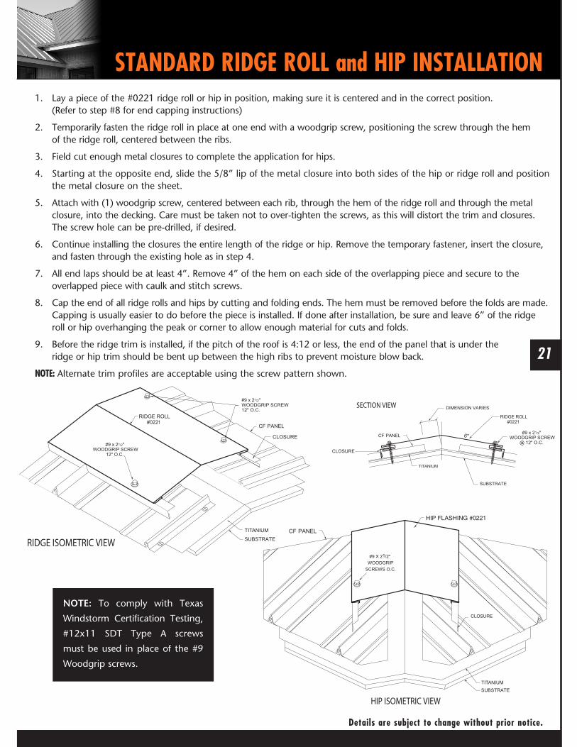
STANDARD RIDGE ROLL and HIP INSTALLATION
Details are subject to change without prior notice.
1. Lay a piece of the #0221 ridge roll or hip in position, making sure it is centered and in the correct position. (Refer to step #8 for end capping instructions)
2. Temporarily fasten the ridge roll in place at one end with a woodgrip screw, positioning the screw through the hem of the ridge roll, centered between the ribs.
3. Field cut enough metal closures to complete the application for hips.
4. Starting at the opposite end, slide the 5/8” lip of the metal closure into both sides of the hip or ridge roll and position the metal closure on the sheet.
5. Attach with (1) woodgrip screw, centered between each rib, through the hem of the ridge roll and through the metal closure, into the decking. Care must be taken not to over-tighten the screws, as this will distort the trim and closures. The screw hole can be pre-drilled, if desired.
6. Continue installing the closures the entire length of the ridge or hip. Remove the temporary fastener, insert the closure, and fasten through the existing hole as in step 4.
7. All end laps should be at least 4”. Remove 4” of the hem on each side of the overlapping piece and secure to the overlapped piece with caulk and stitch screws.
8. Cap the end of all ridge rolls and hips by cutting and folding ends. The hem must be removed before the folds are made. Capping is usually easier to do before the piece is installed. If done after installation, be sure and leave 6” of the ridge roll or hip overhanging the peak or corner to allow enough material for cuts and folds.
9. Before the ridge trim is installed, if the pitch of the roof is 4:12 or less, the end of the panel that is under the ridge or hip trim should be bent up between the high ribs to prevent moisture blow back.
NOTE: Alternate trim profiles are acceptable using the screw pattern shown.
21
NOTE: To comply with Texas
Windstorm Certification Testing,
#12x11 SDT Type A screws
must be used in place of the #9
Woodgrip screws.

22
ENDWALL TO ROOF FLASHING INSTALLATION
Details are subject to change without prior notice.
1. Insert the endwall flashing (#0725) behind the existing wall counter-flashing and attach to the wall using appropriate fasteners. Make sure the receiver hem of the endwall flashing is resting on the top of the roof sheet rib. If required, cap the ends of the trim by cutting and folding a tab. Remove the hems before making the folds.
2. If there is no counter-flashing, install counter-flashing using appropriate fasteners.
3. Slide the 5/8” lip of the metal closure into the receiver hem of the endwall flashing and position the closure on the roof.
4. Attach with one woodgrip screw, centered between each rib, through the hem of the endwall flashing and metal closure, into the decking. Care must be taken not to over-tighten the screws as this will distort the trim and closure. The screw hole can be pre-drilled, if desired.
5. All end laps should be at least 4”. Remove 4” of the hem on the overlapping piece and secure to the overlapped piece with caulk and stitch screws.
NOTE: Alternate trim profiles are acceptable using the screw pattern shown.
NOTE: To comply with Texas
Windstorm Certification Testing,
#12x11 SDT Type A screws
must be used in place of the #9
Woodgrip screws.

1. Apply butyl tape to the bottom side of the J-closure.
2. Install the J-closure flush with the outer edge of the sidewall flashing and parallel to the ribs.
3. Secure with woodgrip screws on 12” centers.
4. Apply butyl tape continuously to top of J-closure.
5. Insert the sidewall flashing behind existing counter-flashing and secure to the J-closure with lap screws.
6. If there is no existing counter-flashing, install counter-flashing to wall with appropriate fasteners.
NOTE: Alternate trim profiles are acceptable using the screw pattern shown.
23
SIDEWALL FLASHING INSTALLATION
Details are subject to change without prior notice.
NOTE: To comply with Texas
Windstorm Certification Testing,
#12x11 SDT Type A screws
must be used in place of the #9
Woodgrip screws.
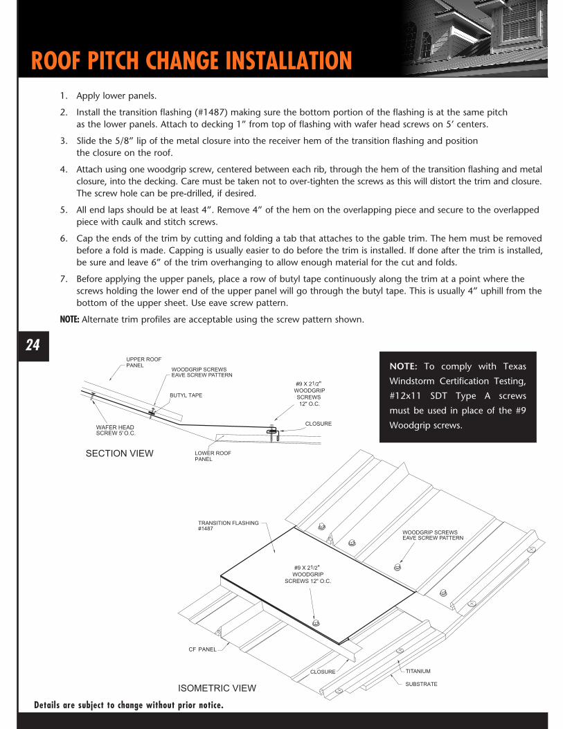
1. Apply lower panels.
2. Install the transition flashing (#1487) making sure the bottom portion of the flashing is at the same pitch as the lower panels. Attach to decking 1” from top of flashing with wafer head screws on 5’ centers.
3. Slide the 5/8” lip of the metal closure into the receiver hem of the transition flashing and position the closure on the roof.
4. Attach using one woodgrip screw, centered between each rib, through the hem of the transition flashing and metal closure, into the decking. Care must be taken not to over-tighten the screws as this will distort the trim and closure. The screw hole can be pre-drilled, if desired.
5. All end laps should be at least 4”. Remove 4” of the hem on the overlapping piece and secure to the overlapped piece with caulk and stitch screws.
6. Cap the ends of the trim by cutting and folding a tab that attaches to the gable trim. The hem must be removed before a fold is made. Capping is usually easier to do before the trim is installed. If done after the trim is installed, be sure and leave 6” of the trim overhanging to allow enough material for the cut and folds.
7. Before applying the upper panels, place a row of butyl tape continuously along the trim at a point where the screws holding the lower end of the upper panel will go through the butyl tape. This is usually 4” uphill from the bottom of the upper sheet. Use eave screw pattern.
NOTE: Alternate trim profiles are acceptable using the screw pattern shown.
24
ROOF PITCH CHANGE INSTALLATION
Details are subject to change without prior notice.
NOTE: To comply with Texas
Windstorm Certification Testing,
#12x11 SDT Type A screws
must be used in place of the #9
Woodgrip screws.

1. Ensure the lower panel is installed completely (except for the top fasteners).
2. Using duckbill pliers squeeze the top 10” of the male side of the lower panel flat to receive the 9” overlap of the upper panel.
3. Install the butyl tape 8” from the top of the lower panel. Do not remove the paper backing from the butyl tape until upper roof panel lap and the top dimension have been confirmed.
4. On the upper panel use duckbill pliers to squeeze the bottom 10” of the locking leg on the female side flat so it will lay flat when overlapping lower panel.
5. Remove paper backing from the butyl tape.
6. Position and place upper panel so that a 9” lap is achieved.
7. Attach the upper panel through the lower panel with woodgrip screws, (3) per panel making sure the screw line is 1” uphill from the butyl tape line.
NOTE: Alternate trim profiles are acceptable using the screw pattern shown.
NOTE: If a longer lap is desired increase all measurements accordingly.
25
STANDARD PANEL ENDLAP
Details are subject to change without prior notice.
NOTE: To comply with Texas
Windstorm Certification Testing,
#12x11 SDT Type A screws
must be used in place of the #9
Woodgrip screws.
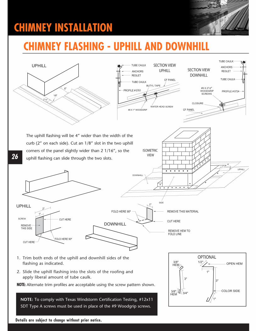
The uphill flashing will be 4” wider than the width of the
curb (2” on each side). Cut an 1/8” slot in the two uphill
corners of the panel slightly wider than 2 1/16”, so the
uphill flashing can slide through the two slots. 26
CHIMNEY INSTALLATION
Details are subject to change without prior notice.
CHIMNEY FLASHING - UPHILL AND DOWNHILL
1. Trim both ends of the uphill and downhill sides of the flashing as indicated.
2. Slide the uphill flashing into the slots of the roofing and apply liberal amount of tube caulk.
NOTE: Alternate trim profiles are acceptable using the screw pattern shown.
DOWNHILL
UPHILL
UPHILL
NOTE: To comply with Texas Windstorm Certification Testing, #12x11
SDT Type A screws must be used in place of the #9 Woodgrip screws.
27
CHIMNEY INSTALLATION
Details are subject to change without prior notice.
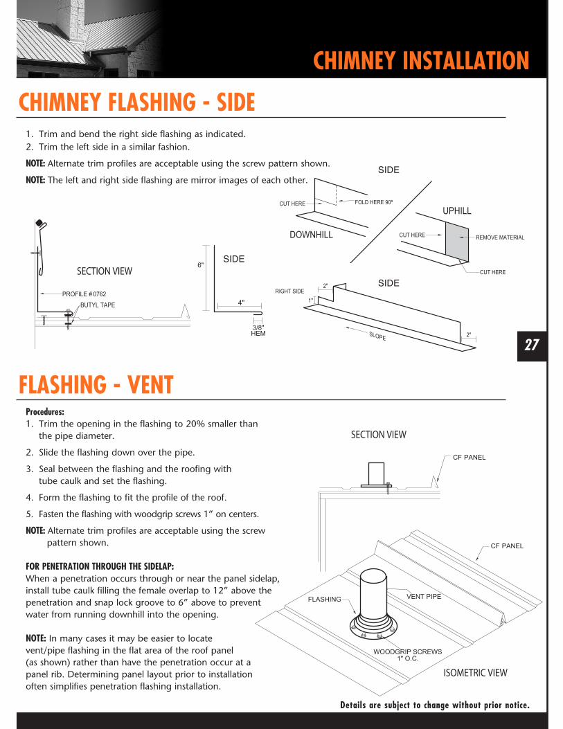
CHIMNEY FLASHING - SIDE
FLASHING - VENTProcedures:1. Trim the opening in the flashing to 20% smaller than the pipe diameter.
2. Slide the flashing down over the pipe.
3. Seal between the flashing and the roofing with tube caulk and set the flashing.
4. Form the flashing to fit the profile of the roof.
5. Fasten the flashing with woodgrip screws 1” on centers.
NOTE: Alternate trim profiles are acceptable using the screw pattern shown.
FOR PENETRATION THROUGH THE SIDELAP:When a penetration occurs through or near the panel sidelap, install tube caulk filling the female overlap to 12” above the penetration and snap lock groove to 6” above to prevent water from running downhill into the opening.
NOTE: In many cases it may be easier to locate vent/pipe flashing in the flat area of the roof panel (as shown) rather than have the penetration occur at a panel rib. Determining panel layout prior to installationoften simplifies penetration flashing installation.
1. Trim and bend the right side flashing as indicated. 2. Trim the left side in a similar fashion.
NOTE: Alternate trim profiles are acceptable using the screw pattern shown.
NOTE: The left and right side flashing are mirror images of each other.
SIDE
SIDE
SIDE

Mueller’s #1, 26 gauge, CF Panels have received the Underwriter’s Laboratory UL2218 Approved Class 4 Premium Rating
M-CFMANUAL-REV.4/18
FIND OUT MORE ABOUT MUELLER, INC.
Call877-2-MUELLER (877-268-3553)This toll-free number connects you to one of our sales locations across the Southwest.
Clickwww.MuellerInc.comOur interactive website offers photos and all the details of our metal products.
Come byMore than 30 locations. Our branches are staffed with experts who are always happy to answer any questions you may have.
Find usOn Facebook, check out our latest news and events.


![Metal Roofing · 877.GO.DECRA [463.3272] | MYTH: Metal roofing is flat, shiny and designed to be used on commercial and agricultural buildings. FACT: DECRA is a family of high performance](https://img.pdfslide.net/doc/110x75/5faef079e393022df92068ba/metal-877godecra-4633272-myth-metal-roofing-is-flat-shiny-and-designed.jpg)