Embed Size (px)
Citation preview

Stratos®Eco 2405 pHUser Manual
www.knick.deLatest Product Information:
093783
2
Subject to change without notice.
Return of Products Under WarrantyPlease contact our Service Team before returning a defective device. Ship the cleaned device to the address you have been given. If the device has been in contact with process fluids, it must be decontaminated/disinfected before shipment. In that case, please attach a corresponding certificate, for the health and safety of our service personnel.
DisposalPlease observe the applicable local or national regulations concerning the disposal of “waste electrical and electronic equipment”.
KnickElektronische Messgeräte GmbH & Co. KGBeuckestraße 2214163 BerlinGermany
Phone: +49 30 80191-0Fax: +49 30 80191-200Web: www.knick.deEmail: [email protected]

3
Table of ContentsSafety Information ......................................................................... 5
Intended Use ....................................................................................................7Registered Trademarks .................................................................................7CD-ROM .............................................................................................................8Safety Instructions .........................................................................................8Short Instructions ...........................................................................................8
Overview of Stratos Eco 2405 pH ................................................ 9Assembly ........................................................................................10
Package Contents .........................................................................................10Mounting Plan ...............................................................................................11Pipe Mounting, Panel Mounting .............................................................12
Installation and Connection .......................................................14Installation Instructions .............................................................................14Terminal Assignments ................................................................................14VP Cable Connection ..................................................................................16VP Cable Assignment ..................................................................................17pH Wiring Examples ....................................................................................18ORP Wiring Example ....................................................................................21Protective Wiring of Relay Outputs .......................................................22
User Interface and Display .........................................................24Operation: Keypad .......................................................................26Safety Functions ...........................................................................27
Sensocheck, Sensoface Sensor Monitoring ........................................27GainCheck Device Self-Test.......................................................................27Automatic Device Self-Test .......................................................................27Hold Mode ......................................................................................................28
Configuration ................................................................................30Menu Structure of Configuration ...........................................................31Overview of Configuration Steps ...........................................................32Output 1 ..........................................................................................................34Output 2 ..........................................................................................................42Temperature Compensation ....................................................................48Calibration Mode ..........................................................................................50

4
Table of ContentsAlarm Settings ...............................................................................................52Limit Function ................................................................................................54Controlling a Rinsing Probe ......................................................................56Connecting a Rinsing System ..................................................................57
Parameters .....................................................................................58Factory Settings of Parameters ...............................................................58Parameters – Individual Settings ............................................................60
Calibration .....................................................................................62pH Calibration ................................................................................................63Automatic Calibration with Calimatic (BUF -xx-) ..............................64Manual Calibration .....................................................................................66Data Entry of Premeasured Electrodes ...............................................68Product Calibration .....................................................................................69ORP Calibration ............................................................................................70
Temp Probe Adjustment .............................................................72Measurement ................................................................................72Diagnostics Functions .................................................................73Error Messages (Error Codes) .....................................................75
Calibration Error Messages .......................................................................77
Operating States ...........................................................................79Sensoface .......................................................................................80Appendix ........................................................................................83
Product Line and Accessories ..................................................................83Specifications .................................................................................................84Buffer Tables ...................................................................................................90Glossary ............................................................................................................98Approvals – Canada ..................................................................................102CSA Control Drawing ...............................................................................104
Index .............................................................................................106Passcodes .....................................................................................110

5
Safety information – Be sure to read and observe the following instructions!The device has been manufactured using state of the art technology and it complies with applicable safety regulations.When operating the device, certain conditions may nevertheless lead to danger for the operator or damage to the device.
CAUTION!Commissioning must be carried out by trained experts. Whenever it is likely that protection has been impaired, the device shall be made inoperative and secured against unintended operation.
The protection is likely to be impaired if, for example:• the device shows visible damage• the device fails to perform the intended measurements• after prolonged storage at temperatures above 70°C• after severe transport stresses
Before recommissioning the device, a professional routine test in accordance with EN 61010-1 must be performed. This test should be carried out at the manufacturer’s factory.
CAUTION!Before commissioning, make sure that the transmitter may be connected with the other equipment.
Safety Information

6

7
Intended Use
The Stratos Eco 2405 pH is used for pH/mV, ORP, and temperature measurement in industry, environment, food processing, and sewage treatment.The sturdy molded enclosure can be fixed into a control panel or mounted on a wall or at a post. The protective hood provides additional protection against direct weather exposure and mechanical damage.The device has been designed for application with commercially available sensors with a nominal zero point at pH 7. It provides two current outputs (for transmission of measured value and tem-perature, for example), two contacts, and a universal power supply 24 ... 230 V AC/DC, AC: 45 ... 65 Hz.
Registered Trademarks
The following names are registered trademarks. For practical reasons they are shown without trademark symbol in this manual.Stratos®Sensocheck®Sensoface®Calimatic®GainCheck®

8
Provided Documentation
CD-ROMComplete documentation:• User manuals• Safety instructions• Quickstart guides
Safety InstructionsIn official EU languages and others.• FM / CSA and Control Drawings• EC Declarations of Conformity
Quickstart GuidesIn German, English, French, Russian, Finnish, Swedish, Spanish, Portuguese, and Chinese. More languages on CD-ROM and on our website: www.knick.de• Installation and Commissioning• Operation• Menu structure• Calibration• Error messages and recommended actions
Stratos® Eco 2405 pHQuickStart
Other languages: www.knick.de
Short Instructions .................................................. 3
Kurzübersicht ........................................................15
QuickStart ..............................................................27
Быстрый старт .....................................................39
Inicio rápido ..........................................................51
Início rápido ..........................................................63
Pikakäynnistys ......................................................75
Snabbstart..............................................................87
快速启动 ................................................................99
Stratos® Eco 2405 SeriesSafety Instructions
FM/CSA, Control DrawingsEC Declarations of Conformity
www.knick.de

9
Overview of Stratos Eco 2405 pH
Overview
11
12
13
14
15
16
19
20
10
9
3
E
D
C
4
5
6
7
8
2
1 Output 1Glass electrode
Reference electrodeAuxiliary electrode
RTD
RTD
Shield
Do not connect terminal !
Do not connect terminal !
Do not connect terminal !
+ Output 1
– Output 1/2
+ Output 2
Relay
Relay
Alarm
Alarm
Power supply
Power supply
pH / mV / temp input
Output 2
R1
Alarm
Power
Not in use
Do not connect terminal !Do not connect terminal !
17
18
Clean
Clean

10
11
10
9
8
7 6 5 4
1
2
3
1 Jumper (2 x)2 Washer (1 x), for conduit mounting:
Place washer between enclosure and nut
3 Cable tie (3 x)4 Hinge pin (1 x), insertable from either
side5 Enclosure screw (4 x)
6 Sealing insert (1 x)7 Rubber reducer (1 x)8 Cable gland (3 x)9 Filler plug (3 x)10 Hexagon nut (5 x)11 Sealing plug (2 x), for sealing in case
of wall mounting
Fig.: Assembling the enclosure
AssemblyPackage ContentsCheck the shipment for transport damage and completeness. The package should contain:• Front unit• Rear unit• Bag containing small parts• CD-ROM with documentation• Specific test report• Passcode sticker

11
AssemblyMounting Plan
144
144
15 4284
8032
2143
10527
726,
2
1 2
3
4
1 Cable gland (3 x)2 Knockouts for cable gland
or 1/2“ conduit, ø 21.5 mm (2 knockouts) Conduits not included!
3 Knockout for pipe mounting (4 x)
4 Knockout for wall mounting (2 x)
Fig.: Mounting plan (All dimensions in mm!)

12
Assembly
40 60132
1
234
5
1
132165
173
1
1 ZU 0276 protective hood (if required)2 Hose clamp with worm gear drive to DIN 3017 (2 x)3 Pipe-mount plate (1 x)4 For vertical or horizontal posts or pipes5 Self-tapping screw (4 x)
Pipe Mounting, Panel Mounting
Fig.: ZU 0274 pipe-mount kit (All dimensions in mm!)
Fig.: ZU 0276 protective hood for wall and pipe mounting (All dimensions in mm!)
13
Assembly
1
2
3
45
max. 2578 27
1...22
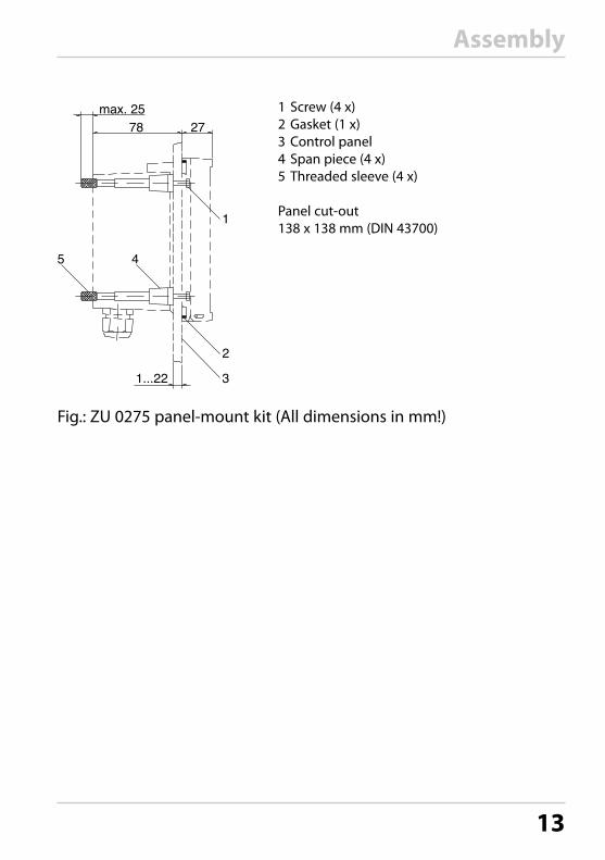
Fig.: ZU 0275 panel-mount kit (All dimensions in mm!)
1 Screw (4 x)2 Gasket (1 x)3 Control panel4 Span piece (4 x)5 Threaded sleeve (4 x) Panel cut-out 138 x 138 mm (DIN 43700)

14
Installation InstructionsCAUTION!• Installation of the Stratos must be carried out by trained experts in
accordance with this instruction manual and as per applicable local and national codes.
• Be sure to observe the technical specifications and input ratings during installation.
• Be sure not to notch the conductor when stripping the insulation.• Before connecting the device to the power supply, make sure that
its voltage lies within the range 20.5 ... 253 V AC/DC.• All parameters must be set by a system administrator prior to
commissioning.
The terminals are suitable for single wires and flexible leads up to 2.5 mm2 (AWG 14).
CAUTION!Additional safety precautions have to be taken for operation in hazardous locations CSA (CLI, DIV2, GPA,B,C,D T4, Ex nA IIC T4) (see Appendix: Approvals)!
Fig.: Stratos Eco 2405 pH terminal assignments
Installation and Connection
Terminal Assignments

15
Installation and Connection
1 ESD shield covering the signal inputs (Screw off for assembly) Note: The cable shield must end under the ESD shield. (Cut lines if required.)
2 Terminals for temperature probe and outer shield3 Terminals for sensor4 Power supply connection
Fig.: Information on installation, rear side of device
The connections to the device must be installed in accordance with the National Electric Code (ANSI NFPA 70) Division 2 hazardous (classified) location non-incendive wiring techniques.
13
2
4
Division 2 Wiring

16
Installation and ConnectionVP Cable Connection
Connecting the sensor to the VP cable
Please note:Cable lengths > 20 m can worsen the response during pH measurement.Be sure to observe the sensor instruction manual.
ZU 0313: 3 mZU 0314: 5 mZU 0315: 10 m

17
Installation and ConnectionVP Cable Assignment
A transparent sensing electrode
B red reference electrode
C gray T3
D blue auxiliary electrode
E white T1
F green T2
S green/yellow outer shield
C = 220 nF
T1/T2 = Temperature probe for 2-wire connection

18
Example 1:pH measurement with monitoring of glass electrode
pH Wiring Examples
Sensor connectionsStratos Eco 2405 pH
All common pH sensors can be connected (with glass electrode and separate or combined reference electrode, with or without temperature detector, with nominal zero at pH 7).
Combination pH electrodeTemp
detector

19
pH Wiring Examples
Sensor connectionsStratos Eco 2405 pH
All common pH sensors can be connected (with glass electrode and separate or combined reference electrode, with or without temperature detector, with nominal zero at pH 7).
e.g.SE531, SE532, SE551, SE553, SE538
e.g.VP cableZU 0313
Yello
w/G
reen
Gre
enW
hite
Red
Tran
spar
ent
Example 2:pH measurement with monitoring of glass electrode, without solution ground (SG), VP connection, e.g. SE531, SE532, SE551, SE553, SE538

20
Example 3:pH measurement with monitoring of glass electrode, sensors with solution ground (SG), VP connection, e.g. SE533, SE552
pH Wiring Examples
Sensor connectionsStratos Eco 2405 pH
All common pH sensors can be connected (with glass electrode and separate or combined reference electrode, with or without tem-perature detector, with nominal zero at pH 7).
e.g.SE533, SE552
Yello
w/G
reen
Gre
enW
hite
Red
Tran
spar
ent
Blue
e.g.VP cableZU 0313

21
ORP Wiring ExampleExample 4:ORP measurement
Sensor connectionsStratos Eco 2405 pH
All common redox sensors can be con-nected (with separate or combined refer-ence electrode, with or without tempera-ture detector).
e.g.SE535
e.g.VP cableZU 0318
Temp detector

22
Protective Wiring of Relay Outputs
1
23
1 2
3
AC applications with inductive load
1 Load2 RC combination, e.g. RIFA PMR 209
Typical RC combinations for 230 V AC: Capacitor 0.1 µF / 630 V Resistor 100 ohms / 1 W
3 Contact
Protective Wiring of Relay Contacts
Relay contacts are subjected to electrical erosion. Especially with inductive and capacitive loads, the service life of the contacts will be reduced. For suppression of sparks and arcing, components such as RC combinations, nonlinear resistors, series resistors and diodes should be used.

23
Protective Wiring of Relay OutputsTypical Protective Wiring Measures
A: DC application with inductive loadB: AC/DC applications with capacitive loadC: Connection of incandescent lamps (resistive load)
A1 Inductive loadA2 Free-wheeling diode, e.g. 1N4007 (Observe polarity)A3 ContactB1 Capacitive loadB2 Resistor, e.g. 8 Ω / 1 W at 24 V / 0.3 AB3 ContactC1 Incandescent lamp, max 60 W / 230 V, 30 W / 115 VC3 Contact
WARNING!Make sure that the maximum ratings of the relay contacts are not exceeded even during switching!

24
1 Display Mode indicators (no keys),
from left to right: - Measuring mode - Calibration mode - Alarm - Wash contact - Configuration mode
2 Alarm LED3 Keypad
1
2
3
4
User Interface
User Interface and Display

25
User Interface and Display
1 2 3 4 5 6 7 8 9 10
11
1213
1617
20
18
19
15 14
1 Passcode entry2 Not in use3 Temperature4 Current output5 Limit values6 Alarm7 Sensocheck8 Calibration9 Interval/response time10 Wash contact11 Measurement symbol12 Press enter to proceed 13 Bar for identifying the device status,
above mode indicators, from left to right: - Measuring mode - Calibration mode - Alarm - Not in use - Configuration mode
14 Secondary display15 Manual temperature specification16 Hold mode active17 Waiting time running18 Sensor data19 Main display20 Sensoface
Display

26
User Interface and Display
cal Start, end calibrationconf Start, end configuration • Select digit position
(selected position blinks)• Menu navigation
• Edit digit• Menu navigation
enter • Calibration: Continue in program sequence• Configuration: Confirm entries, next configuration step• Measuring mode: Display output current
cal enter Cal Info: Display of asymmetry potential (zero) and slope
conf enter Error Info: Display of last error message + Start GainCheck device self-test
Operation: Keypad

27
Safety FunctionsSensocheck, Sensoface Sensor MonitoringSensocheck continuously monitors the sensor and its wiring.Sensocheck can be switched off (Configuration, Pg 52).
Sensoface provides information on the sensor condition. The asymmetry potential (zero), slope and response time during calibration are evaluated. The three Sensoface indica-tors provide the user with information on wear and required maintenance of the sensor.
GainCheck Device Self-TestA display test is carried out, the software version is displayed, and the memory and measured-value transfer are checked.
Start GainCheck device self-test: +
Automatic Device Self-TestThe automatic device self-test checks the memory and measured- value transfer. It runs automatically in the background at fixed intervals.

28
Hold Mode
Display:
The Hold mode is a safety state during configuration and calibration. Output current is frozen (Last) or set to a fixed value (Fix). Alarm and limit contacts are disabled. If the calibration or configuration mode is exited, the device remains in the Hold mode for safety reasons. This prevents undesirable reactions of the connected peripherals due to incorrect configuration or calibra-tion. The measured value and “HOLD” are displayed alternately. The device only returns to measuring mode after enter is pressed and 20 seconds have passed.
Configuration mode is also exited automatically 20 minutes (timeout) after the last keystroke. The device returns to measuring mode.
Timeout is not active during calibration.
Behavior of output signal:
Last: The output current is frozen at its last value. Recommended for short configuration procedures. The process should not change decisively during configuration. Changes are not noticed with this setting!
Fix: The output current is set to a value that is noticeably different from the process value in order to signal the control system that the device is being worked at.
See Configuration Pg 40.
Safety Functions

29
Safety FunctionsAlarm
Alarm delay is 10 seconds.During an error message the alarm LED blinks.
Error messages can also be signaled by a 22 mA output current.
The alarm contact is activated by alarm or power failure, see also Pg 53.

30
ConfigurationIn the Configuration mode you set the device parameters.
Activation conf Activate by pressing conf
Enter passcode “1200“ Edit parameter using and , confirm/proceed using enter.(End by pressing conf, then enter.)
HOLD
During configu-ration the device remains in the Hold mode.
The output current is frozen (at its last value or at a preset fixed value, depend-ing on the configuration), limit and alarm contacts are inactive. Sensoface is off, “Configuration” mode indicator is on.
HOLD icon
Input errors The configuration parameters are checked during the input. In the case of an incorrect input ”Err” is displayed for approx. 2 sec. The incorrect param-eters cannot be stored. Input must be repeated.
End conf
enter
End by pressing conf. The measured value and Hold are displayed alternately, “enter” blinks. Press enter key to end the Hold mode. The measured value is displayed. The output current remains frozen for another 20 sec (HOLD icon on, “hourglass” blinks).

31
ConfigurationMenu Structure of Configuration
The configuration steps are assigned to different menu groups. Using the arrow keys, you can jump between the individual menu groups.Each menu group contains menu items for setting the parameters.Pressing enter opens a menu item. The values are edited using the arrow keys. Pressing enter confirms/saves the settings.Return to measurement: Press conf.
Select menu group Menu group Code Display Select menu
item
Output 1 o1.
Menu item 1
Menu item 2
...
Menu item ...
Output 2 o2.
Temperature compensation tc.
Calibration mode CA.
Alarm settings AL.
Relay rL.
Rinsing probes
Previous menu group:
enter
enter
enter
enter

32
ConfigurationOverview of Configuration Steps
Code Menu Selection / Defaultout1 Output 1
o1.UnIT Select process variable pH / ORP
o1. rNG Select current range 0-20 mA / 4-20 mA
o1. 4mA Enter current start xxxx
o1.20mA Enter current end xxxx
o1.FtME Time constant of output filter xxxx SEC
o1.FAIL 22 mA signal in the case of error ON / OFF
o1.HoLD Signal behavior during HOLD Last / Fix
o1.FIX Enter fixed value xxx.x mA
out2 Output 2
o2.UnIT Select temperature unit °C / °F
o2. rTD Select temperature probe Pt100/Pt1000/NTC30/NTC8.55/Balco3000
o2.rNG Select current range 0-20 mA / 4-20 mA
o2. 4mA Enter current start xxx.x
o2.20mA Enter current end xxx.x
o2.FtME Time constant of output filter xxxx SEC
o2.FAIL 22 mA signal for temp error ON / OFF
o2.HoLD Signal behavior during HOLD Last / Fix
o2.FIX Enter fixed value xxx.x mA
tc. Temperature compensation
tc. MEAS Temp detection during meas Auto/man (man: xxx.x °C)
tc. CAL Temp detection during cal Auto/man (man: xxx.x °C)
tc. LIN Enter TC process medium xx.xx %/K
CAL Calibration mode
CA. SOL Select calibration mode BUF/MAN/DAT
CA.tiME Enter cal timer interval xxxx h

33
Configuration
Code Menu Selection / DefaultALrt Alarm settings
AL.SnSO Select Sensocheck ON / OFF
rLAY Relay 1: Limit
L1.FCT Select contact function Lo / Hi
L1.tYP Select contact response N/O / N/C
L1.LEVL Enter setpoint xxxx
L1.HYS Enter hysteresis xxxx
L1.dLY Enter delay xxxx SEC
Cleaning probes
Rinse interval
Rinse duration
Contact response

34
Configuration
1 Press conf key.2 Enter passcode 1200.3 Output 1 menu group is displayed. All items
of this menu group are indicated by the “o1.” code.
4 Press enter to select menu, edit using arrow keys (see Pg 35). Confirm (and proceed) using enter.
5 End: Press conf, then enter.Output 1:
Output 1Process variable (pH/ORP)
1
2
3
o1.UnIT Select process variableo1. rNG Select 0-20 / 4-20 mAo1. 4mA Enter current starto1.20mA Enter current endo1.FtME Set output filtero1.FAIL 22 mA for erroro1.HoLD HOLD mode
4
5
conf
enter
enterconf

35
Configuration
Code Display Action Choiceso1. Select variable pH/ORP
Select using arrow key. Press enter to proceed.
pH/ORP
Note: Characters represented in gray are blinking and can be edited.

36
Configuration
1 Press conf key.2 Enter passcode 1200.3 Output 1 menu group is displayed. All items
of this menu group are indicated by the “o1.” code.
4 Press enter to select menu, edit using arrow keys (see Pg 37). Confirm (and proceed) using enter.
5 End: Press conf, then enter.
Output 1Output current range, current start, current end
o1.UnIT Select process variableo1. rNG Select 0-20 / 4-20 mAo1. 4mA Enter current starto1.20mA Enter current endo1.FtME Set output filtero1.FAIL 22 mA for erroro1.HoLD HOLD mode
4
Output 1:
1
2
3
5
conf
enterconf
enter enter

37
Configuration
Code Display Action Choiceso1. Set output current range
Select usingkey, press enter to proceed.
4 - 20 mA(0 - 20 mA)
Current start Enter lower end of scale, depending on process variable selected (pH or ORP) Select usingkey, edit number using key, press enter to proceed.
pH -2 ... 16(-1500 mV... +1500 mV)
Current end Enter upper end of scale, depending on measured variable selected (pH or ORP) Select usingkey, edit number using key, press enter to proceed.
pH -2 ... 16(-1500 mV... +1500 mV)
Assignment of Measured Values:Current Start and Current End
Example 1: Range pH 0 ... 14 Example 2: Range pH 5 ... 7 Advantage: Higher resolution in
range of interest
Output current
[pH]
20 4
14
0
7
5[mA]
Output current
[pH]
20 4 [mA]

38
Configuration
1 Press conf key.2 Enter passcode 1200.3 Output 1 menu group is displayed. All items
of this menu group are indicated by the “o1.” code.
4 Press enter to select menu, edit using arrow keys (see Pg 39). Confirm (and proceed) using enter.
5 End: Press conf, then enter.
Output 1Time constant of output filter
o1.UnIT Select process variableo1. rNG Select 0-20 / 4-20 mAo1. 4mA Enter current starto1.20mA Enter current endo1.FtME Set output filtero1.FAIL 22 mA for erroro1.HoLD HOLD mode
4
Output 1:
1
2
3
5
conf
enterconf
enter enter
39
Configuration
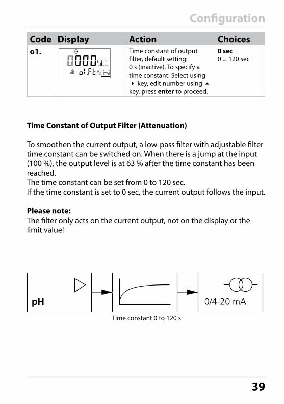
Code Display Action Choiceso1. Time constant of output
filter, default setting: 0 s (inactive). To specify a time constant: Select using key, edit number using key, press enter to proceed.
0 sec0 ... 120 sec
Time Constant of Output Filter (Attenuation)
To smoothen the current output, a low-pass filter with adjustable filter time constant can be switched on. When there is a jump at the input (100 %), the output level is at 63 % after the time constant has been reached.The time constant can be set from 0 to 120 sec.If the time constant is set to 0 sec, the current output follows the input.
Please note:The filter only acts on the current output, not on the display or the limit value!
Time constant 0 to 120 s

40
Configuration
1 Press conf key.2 Enter passcode 1200.3 Output 1 menu group is displayed. All items
of this menu group are indicated by the “o1.” code.
4 Press enter to select menu, edit using arrow keys (see Pg 41). Confirm (and proceed) using enter.
5 End: Press conf, then enter.
Output 1Output current during Error and HOLD
o1.UnIT Select process variableo1. rNG Select 0-20 / 4-20 mAo1. 4mA Enter current starto1.20mA Enter current endo1.FtME Set output filtero1.FAIL 22 mA for erroro1.HoLD HOLD mode
4
Output 1:
1
2
3
5
conf
enterconf
enter enter

41
Configuration
Code Display Action Choiceso1. 22 mA signal for error
message Select usingkey, press enter to proceed.
OFF (ON)
Output signal during HOLD LAST: During HOLD the last measured value is main-tained at the outputFIX: During HOLD a value (to be entered) is maintained at the outputSelect usingkey, press enter to proceed.
LAST(FIX)
Only with FIX selected:Enter current which is to flow at the output during HOLDSelect position usingkey and edit number using key.Press enter to proceed.
21.0 mA(00.0 ...21.0 mA)
Output Signal During HOLD:
Output current[mA]
Output signal HOLDSetting FIX = 21.0 mA
HOLD active
21
4
Output signal HOLDSetting LAST
HOLD active
42
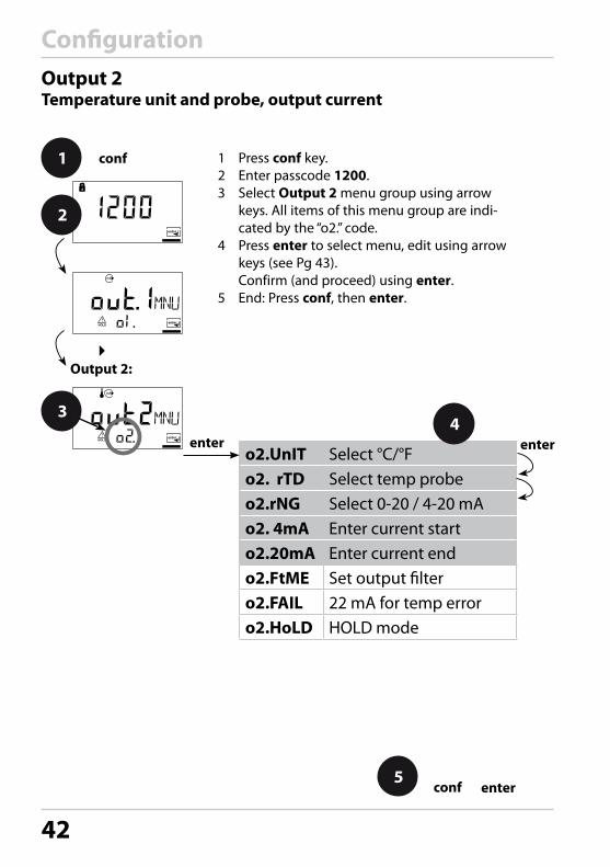
Configuration
1 Press conf key.2 Enter passcode 1200.3 Select Output 2 menu group using arrow
keys. All items of this menu group are indi-cated by the “o2.” code.
4 Press enter to select menu, edit using arrow keys (see Pg 43). Confirm (and proceed) using enter.
5 End: Press conf, then enter.
Output 2Temperature unit and probe, output current
o2.UnIT Select °C/°Fo2. rTD Select temp probeo2.rNG Select 0-20 / 4-20 mAo2. 4mA Enter current starto2.20mA Enter current endo2.FtME Set output filtero2.FAIL 22 mA for temp erroro2.HoLD HOLD mode
4
Output 2:
3
1
2
5
conf
enterconf
enter enter

43
Configuration
Code Display Action Choiceso2. Specify temperature unit
Select usingkey, press enter to proceed.
°C(°F)
Select temperature probeSelect usingkey, press enter to proceed.
Pt1000(Pt100, NTC30, NTC8.55, Bco3000)
Select output current rangeSelect usingkey, press enter to proceed.
4 - 20 mA(0 - 20 mA)
Current start: Enter lower end of scale.Select usingkey, edit number using key, press enter to proceed.
000.0 °C
Current start: Enter upper end of scale.Select usingkey, edit number using key, press enter to proceed.
100.0 °C
Process Temperature: Current Start and Current End
Example 1: Range 0 ... 100 °C Example 2: Range 50 ... 70 °C Advantage: Higher resolution in
range of interest
Output current
[°C]
20 4
100
0
70
50[mA]
Output current
[°C]
20 4 [mA]
Process temperature Process temperature

44
Configuration
1 Press conf key.2 Enter passcode 1200.3 Select Output 2 menu group using arrow
keys. All items of this menu group are indi-cated by the “o2.” code.
4 Press enter to select menu, edit using arrow keys (see Pg 45). Confirm (and proceed) using enter.
5 End: Press conf, then enter.
Output 2Time constant of output filter
o2.UnIT Select °C/°Fo2. rTD Select temp probeo2.rNG Select 0-20 / 4-20 mAo2. 4mA Enter current starto2.20mA Enter current endo2.FtME Set output filtero2.FAIL 22 mA for temp erroro2.HoLD HOLD mode
4
Output 2:
3
1
2
5
conf
enterconf
enter enter

45
Configuration
Code Display Action Choiceso2. Time constant of output filter
Default setting: 0 sec (inactive). To specify a time constant: Select using key, edit number using key, press enter to proceed.
0 sec(0 ... 120 sec)
Time Constant of Output Filter
To smoothen the current output, a low-pass filter with adjustable filter time constant can be switched on. When there is a jump at the input (100 %), the output level is at 63 % after the time constant has been reached.The time constant can be set from 0 to 120 sec.If the time constant is set to 0 sec, the current output follows the input.
Please note:The filter only acts on the current output, not on the display!
Time constant 0 to120 s

46
Configuration
1 Press conf key.2 Enter passcode 1200.3 Select Output 2 menu group using arrow
keys. All items of this menu group are indi-cated by the “o1.” code.
4 Press enter to select menu, edit using arrow keys (see Pg 47). Confirm (and proceed) using enter.
5 End: Press conf, then enter.
Output 2Temperature error, output current during HOLD
Output 2:
3
1
2
o2.UnIT Select °C/°Fo2. rTD Select temp probeo2.rNG Select 0-20 / 4-20 mAo2. 4mA Enter current starto2.20mA Enter current endo2.FtME Set output filtero2.FAIL 22 mA for temp erroro2.HoLD HOLD mode
5
conf
enterconf
enter enter4

47
Configuration
Code Display Action Choiceso2. 22 mA signal for error
message Select usingkey, press enter to proceed.
OFF (ON)
Output signal during HOLD LAST: During HOLD the last measured value is main-tained at the outputFIX: During HOLD a value (to be entered) is maintained at the outputSelect usingkey, press enter to proceed.
LAST(FIX)
Only with FIX selected:Enter current which is to flow at the output during HOLDSelect position usingkey and edit number using key.Press enter to proceed.
21.0 mA(00.0 ...21.0 mA)
Output Signal During HOLD:
Output current[mA]
Output signal HOLDSetting FIX = 21.0 mA
HOLD active
21
4
Output signal HOLDSetting LAST
HOLD active

48
Configuration
Temp compensation:
1 Press conf key.2 Enter passcode 1200.3 Select Temperature compensation menu
group using arrow keys. All items of this menu group are indicated by the “tc.” code.
4 Press enter to select menu, edit using arrow keys (see Pg 49). Confirm (and proceed) using enter.
5 End: Press conf, then enter.
Temperature CompensationTemp detection for meas/cal, TC process medium
tc.MEAS Temp during meas.tc. CAL Temp during calibrationtc. LIN TC process medium
43
1
2
5
conf
enterconf
enter enter

49
Configuration
Code Display Action Choicestc. Select temp detection
during measurement (Auto/MAN)AUTO: Temp detection with temperature probe MAN: Manual temperature inputSelect usingkey, press enter to proceed.
AUT (MAN)
Only with manual temp detection selected (MAN): Enter temperature. Select position using key and edit number usingkey. Press enter to proceed.
25.0 °C(xxx.x °C)
Select temp detection d uring calibration (Auto/MAN)Select usingkey, press enter to proceed.
AUT (MAN)
Only with manual temp detection selected (MAN): Enter temperature. Select position using key and edit number usingkey. Press enter to proceed.
25.0 °C(xxx.x °C)
For pH measurement only:Enter temperature com-pensation of the process medium Select position using key and edit number usingkey. Press enter to proceed.
00.00 %/K(-19.99 ... 19.99 %/K)

50
Configuration
1 Press conf key.2 Enter passcode 1200.3 Select Calibration mode menu group using
arrow keys. All items of this menu group are indicated by the “CA.” code.
4 Press enter to select menu, edit using arrow keys (see Pg 51). Confirm (and proceed) using enter.
5 End: Press conf, then enter.
Calibration Mode
CA. SOL Calibration modeCA. tiME Cal timer interval
4
Calibration mode:
3
1
2
5
conf
enterconf
enter enter

51
Configuration
Code Display Action ChoicesCA. For pH measurement only:
Select calibration mode BUF: Calibration with Calimatic automatic buffer selection. To do so, you must select your buffer set:
-01- BUF: Mettler-Toledo
-02-BUF: Knick CaliMat (Merck Titrisols, Riedel Fixanals)
-03- BUF: Ciba (94)
-04-BUF: NIST technical buffers
-05-BUF: NIST standard buffers
-06-BUF: HACH buffers
-07-BUF: WTW technical buffers
-08- BUF: Hamilton Duracal
MAN: Calibration with manual buffer entryDAT: Entry of asymmetry potential and slope of pre-measured electrodes. Select usingkey, press enter to proceed.
-01-BUF -02-BUF/-03-BUF/-04-BUF/-05-BUF/-06-BUF/-07-BUF/ -08-BUF/ MAN/ DAT)
Enter calibration interval:Entry of time interval within which the device is to be calibrated.With a time interval of 0000 hrs, the calibration timer is not active. Select usingkey, edit number using key, press enter to proceed.
0000 h (0000 ... 9999 h)

52
Configuration
1 Press conf key.2 Enter passcode 1200.3 Select Alarm settings menu group using
arrow keys. All items of this menu group are indicated by the “AL.” code.
4 Press enter to select menu, edit using arrow keys (see Pg 53). Confirm (and proceed) using enter.
5 End: Press conf, then enter.
Alarm Settings
AL. SnSO Select Sensocheck
4
Alarm settings:
3
1
2
5
conf
enterconf
enter

53
Configuration
Code Display Action ChoicesAL. Select Sensocheck
(continuous monitoring of glass and reference electrode)Select usingkey, press enter to proceed.
ON/OFF
15
16
Alarm Alarm Contact
The alarm contact is closed during normal operation (N/C). It opens in the case of alarm or power outage. As a result, a failure message is provided even in the case of line breakage (fail-safe behavior). For contact ratings, see Specifications.
Error messages can also be signaled by a 22 mA output current (see Pg 40,
The operating behavior of the alarm contact is shown on Pg 79.
The alarm delay acts on the LED, the 22 mA signal and the alarm contact.
46, 75).

54
ConfigurationLimit FunctionRelay
L1.FCT Contact functionL1.tYP Contact responseL1.LEVL Enter setpointL1.HYS Enter hysteresisL1.dLY DelayLimit function:
4
1 Press conf key.2 Enter passcode 1200.3 Select Limit function menu group using arrow
keys. All items of this menu group are indicated by the “L1.” code.
4 Press enter to select menu, edit using arrow keys (see Pg 54). Confirm (and proceed) using enter.
5 End: Press conf, then enter.
3
1
2
5
conf
enterconf
enter
enter

55
Configuration
Code Display Action ChoicesL1. Contact function
(see below for function principle)Select usingkey, press enter to proceed.
Lo(HI)
Contact responseN/C: normally closed contactN/O: normally open contactSelect usingkey, press enter to proceed.
N/C(N/O)
SetpointSelect usingkey, edit number using key, press enter to proceed.
00.00 pH(xx.xx pH)
HysteresisSelect usingkey, edit number using key, press enter to proceed.
00.50 pH(xx.xx pH)
DelayThe contact is activated with delay (deactivated without delay)Select usingkey, edit number using key, press enter to proceed.
0010 sec(0 ... 9999 sec)
Limit Lo
Hysteresis +Setpoint
contact0
1
Signal
Limit Hi
Hysteresis -
Signal
Setpoint
contact0
1

56
1 Taste conf drücken.2 Passcode 1200 eingeben.3 Menügruppe Grenzwertfunktion mit
Pfeiltasten auswählen. Für alle Menüpunkte dieser Menügruppe erscheint der code “rL.” im Display.
4 Wahl der Menüpunkte mit enter-Taste, Ändern mit Pfeiltasten (siehe Seite 56). Bestätigen (und weiter) mit enter.
5 Beenden: Taste conf, dann enter.
Rinsing intervalRinse durationContact response
Rinse contact:
4
1 Press conf key.2 Enter passcode 1200.3 Select Rinsing probes menu group using
arrow keys. All items of this menu group are indicated by the “Pb.” code.
4 Press enter to select menu, edit using arrow keys (see next page). Confirm (and proceed) using enter.
5 End: Press conf, then enter.
3
1
2
5
conf
enterconf
enter
enter
Controlling a Rinsing Probe“Clean” contact
Configuration

57
Code Display Action ChoicesRinsing intervalSelect using key, enter number using , press enter to proceed.
0.000 h(x.xxx h)
Rinse duration Select using key, enter number using , press enter to proceed.
0060 s(xxxx s)
Contact responseN/C: normally closed contactN/O: normally open contactSelect using , press enter to proceed.
17
18
e.g. spray cleaning
Power supply
Connecting a Rinsing SystemThe “Clean” contact can be used to connect a simple spray cleaning system. Rinse duration and rinsing interval are defined during configuration.
Clean
Configuration

58
ParametersFactory Settings of Parameters
Activation: Simultaneously press conf + right arrow key and enter passcode “4321“. The lower display line reads “Clear“. To prevent accidental resetting, “NO“ is set as default (blinking in the main display). Press one of the arrow keys to select “YES“ and confirm by pressing enter.
CAUTION! Your data (also calibration data) will be overwritten by the factory settings!
Code Parameters Factory settingo1.UnIT pH/ORP unit pH
o1. rNG 0/4 ... 20 mA 4-20 mA
o1. 4mA Current start 00.00 pH
o1.20mA Current end 14.00 pH
o1.FtME Filter time 0 s
o1.FAIL 22mA signal OFF
o1.HoLD HOLD response Last
o1.FIX Fix current 021.0 mA
o2.UnIT Unit °C / °F °C
o2.rTD Temp probe Pt1000
o2.rNG 0/4 ... 20mA 4-20 mA
o2. 4mA Current start 000.0 °C
o2.20mA Current end 100.0 °C
o2.FtME Filter time 0 s
o2.FAIL 22mA signal OFF
o2.HoLD HOLD response Last
o2.FIX Fix current 021.0 mA

59
Parameters
Please note: Fill in your configuration data on the following pages.
Code Parameters Factory settingtc.MEAS TC measurement Auto
tc.MEAS Measuring temp 025.0 °C
tc. CAL Calibration Auto
tc. CAL Calibration temp 025.0 °C
tc. LIN TC medium 00.00 %/K
CA. SOL Cal solution -01-BUF
CA.tiME Calibration interval 0000 h
AL.SnSO Sensocheck OFF
L1.FCT Contact function Lo
L1.tYP Contact response N/C
L1.LEVL Setpoint 00.00 pH
L1.HYS Hysteresis 00.50 pH
L1.dLY Delay 0010 sec
Rinsing interval 000.0 h
Rinse duration 0060 s
Contact type N/C
Please note: Factory settings for the calibration data are 98 % (slope) and 0 mV (asymmetry potential).

60
ParametersParameters – Individual Settings
Code Parameter Setting
o1.UnIT pH/ORP unit
o1. rNG 0/4 ... 20 mA
o1. 4mA Current start
o1.20mA Current end
o1.FtME Filter time
o1.FAIL 22mA signal
o1.HoLD HOLD response
o1.FIX Fix current
o2.UnIT Unit °C / °F
o2.rTD Temp probe
o2.rNG 0/4 ... 20mA
o2. 4mA Current start
o2.20mA Current end
o2.FtME Filter time
o2.FAIL 22mA signal

61
Parameters
Code Parameter Setting
o2.HoLD HOLD response
o2.FIX Fix current
tc.MEAS TC measurement
tc.MEAS Measuring temp
tc. CAL Calibration
tc. CAL Calibration temp
tc. LIN TC medium
CA. SOL Cal solution
CA.tiME Cal interval
AL.SnSO Sensocheck
L1.FCT Contact function
L1.tYP Contact response
L1.LEVL Setpoint
L1.HYS Hysteresis
L1.dLY Delay
Rinsing interval
Rinse duration
Contact type

62
CalibrationCalibration adjusts the device to the sensor.Activation cal Activate by pressing cal
Enter passcode “1100“ or “1105“ Select using key.Edit parameter using . Press enter to proceed.(End by pressing cal, then enter.)
HOLD
During calibra-tion the device remains in the Hold mode.
During calibration the device remains in the Hold mode for reasons of safety. The output current is frozen (at its last value or at a preset fixed value, depending on the configuration), limit and alarm contacts are inactive. Sensoface is off, “Calibration” mode indicator is on.
HOLD icon
Input errors The calibration parameters are checked during the input. In the case of an incor-rect input ”Err” is displayed for approx. 2 sec. The incorrect parameters cannot be stored. Input must be repeated.
End enter
enter
End by pressing enter (abort using cal).The measured value and Hold are displayed alternately, “enter” blinks. Sensoface is active.Press enter key to end the Hold mode. The measured value is displayed. The output current remains frozen for another 20 sec (HOLD icon on, “hourglass” blinks).

63
CalibrationpH Calibration
Calibration is used to adapt the device to the individual sensor char-acteristics, namely asymmetry potential and slope. Calibration can be performed with Calimatic automatic buffer recognition, with manual buffer input, by entering premeasured electrode data, or by sampling the product.
CAUTION!• All calibration procedures must be performed by trained personnel.
Incorrectly set parameters may go unnoticed, but change the measuring properties.
• The response time of the sensor and temperature probe is consid-erably reduced when the sensor is first moved about in the buffer solution and then held still.
• The device can only operate properly when the buffer solutions used correspond to the configured set. Other buffer solutions, even those with the same nominal values, may demonstrate a different temperature response. This leads to measurement errors.
• For calibration without buffer solutions, refer to “Product Calibration“.
64
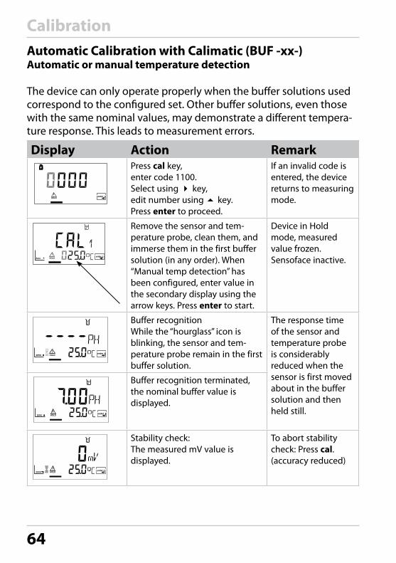
CalibrationAutomatic Calibration with Calimatic (BUF -xx-)Automatic or manual temperature detection
The device can only operate properly when the buffer solutions used correspond to the configured set. Other buffer solutions, even those with the same nominal values, may demonstrate a different tempera-ture response. This leads to measurement errors.
Display Action RemarkPress cal key, enter code 1100.Select using key, edit number using key. Press enter to proceed.
If an invalid code is entered, the device returns to measuring mode.
�
Remove the sensor and tem-perature probe, clean them, and immerse them in the first buffer solution (in any order). When “Manual temp detection” has been configured, enter value in the secondary display using the arrow keys. Press enter to start.
Device in Hold mode, measured value frozen.Sensoface inactive.
Buffer recognitionWhile the “hourglass” icon is blinking, the sensor and tem-perature probe remain in the first buffer solution.
The response time of the sensor and temperature probe is considerably reduced when the sensor is first moved about in the buffer solution and then held still.
Buffer recognition terminated,the nominal buffer value is displayed.
Stability check:The measured mV value is displayed.
To abort stability check: Press cal. (accuracy reduced)

65
Calibration
Display Action Remark
��
Calibration with the first buffer is terminated. Remove the sensor and temp probe from the first buffer solution and rinse them thoroughly.
• One-point calibration: End by pressing cal. Slope [%] and asymmetry potential [mV] of the sensor are displayed. Press enter to proceed.
For one-point calibration only:
• Two-point calibration: Immerse sensor and tempera-ture probe in the second buffer solution. Press enter to start.
The calibration process runs again as for the first buffer.
Retract sensor and temp probe out of second buffer, rinse off, re-install. Repeat calibration: press cal End calibration: press enter
The slope and asym-metry potential of the sensor (based on 25 °C) are displayed.
pH value and “Hold” are displayed alternately. Sensoface active, “enter” blinks. Press enter to proceed. Hold is deactivated after 20 s.
Confirmation prompt.

66
CalibrationManual Calibration Automatic or manual temperature detection
For calibration with manual buffer specification, you must enter the pH value of the buffer solution used in the device for the proper temperature. This presetting enables calibration with any desired buf-fer solution. The MAN calibration mode and the type of temperature detection are selected in the configuration mode.
Display Action RemarkPress cal key, enter code 1100.Select using key, edit number using key. Press enter to proceed.
If an invalid code is entered, the device returns to measuring mode.
�
Remove the sensor and tem-perature probe, clean them, and immerse them in the first buffer solution (in any order). When “Manual temp detection” has been configured, enter value in the secondary display using the arrow keys. Press enter to start.
Device in Hold mode, measured value frozen.Sensoface inactive.
Enter the pH value of your buffer solution for the proper tempera-ture. While the “hourglass” icon is blinking, the sensor and temper-ature probe remain in the buffer solution.
The response time of the sensor and temperature probe is considerably reduced when the sensor is first moved about in the buffer solution and then held still.
Stability check:The measured mV value is displayed.
To abort stability check: Press cal (accuracy reduced)

67
Calibration
Display Action Remark
��
Calibration with the first buffer is terminated. Remove the sensor and temp probe from the first buffer solution and rinse them thoroughly.
• One-point calibration: End by pressing cal. Slope [%] and asymmetry potential [mV] of the sensor are displayed. Press enter to proceed.
For one-point calibration only:
• Two-point calibration: Immerse sensor and tempera-ture probe in the second buffer solution. Enter pH value of second buffer solution. Press enter to start.
The calibration pro-cess runs again as for the first buffer.
Retract sensor and temp probe out of second buffer, rinse off, re-install. Repeat calibration: press cal End calibration: press enter
The slope and asym-metry potential of the sensor (based on 25 °C) are displayed.
pH value and “Hold” are displayed alternately. Sensoface active, “enter” blinks. Press enter to proceed. Hold is deactivated after 20 s.
Confirmation prompt.

68
CalibrationData Entry of Premeasured Electrodes
You can directly enter the values for slope and asymmetry potential of a sensor. The values must be known, e.g. determined beforehand in the laboratory.The DAT calibration mode must have been preset during configuration.
Display Action RemarkPress cal key, enter code 1100.Select usingkey, edit number using key. Press enter to proceed.
If an invalid code is entered, the device returns to measuring mode.
��
Ready for calibrationPress enter to start.
Device in Hold mode, measured value frozen.Sensoface inactive.
Enter asymmetry potential [mV]. Select usingkey, edit number using key. Press enter to proceed.
Enter slope [%]. Select usingkey, edit number using key. Press enter to proceed.
The device displays the new slope and asymmetry potential (at 25 °C).Press enter to proceed.
pH value and “Hold” are dis-played alternately. Sensoface active, “enter” blinks. Press enter to proceed. Hold is deactivated after 20 s.
Confirmation prompt.

69
CalibrationProduct Calibration Calibration by comparison
Product calibration is a 1-point calibration. During product calibration the sensor remains in the process.
Procedure: Open the product calibration menu. Measure the pH value of the process using a reference meter – e.g. in a bypass or in a sample taken from the process. Then enter this reference value in the analyzer (upper display). The analyzer calculates the new zero point.
Please note: The slope remains unchanged, e.g. 98 % (factory setting).
Display Action RemarkPress cal key, enter code 1105.Presskey to select position, enter number usingkey, confirm by pressing enter.
If an invalid code is entered, the device returns to measuring mode.
The lower display shows the process pH value measured by the device.Enter the measured reference value in the upper line.Press enter to proceed.
The pH value should not change between the reference mea-surement and enter. Otherwise, you would have to repeat the calibration.
Display of slope and new zero point. End calibration by pressing enter.
New calibration: Press cal.
The new value is shown in the main display alternately with “Hold”. Sensoface is active, “enter” blinks. End by pressing enter.
After end of calibra-tion, the outputs remain in Hold mode for approx. 20 sec.

70
CalibrationORP Calibration
ORP calibration mode is automatically preset when ORP measurement is configured. The potential of a redox (ORP) sensor is calibrated using a redox buffer solution. In the course of that, the difference between the measured potential and the potential of the calibration solution is determined according to the following equation. During measure-ment the Stratos adds this difference to the measured potential.
mVORP
= displayed ORP
mVORP
= mVmeas
+ ∆mV mVmeas
= direct sensor potential
∆mV = delta value, determined during calibration
The sensor potential can also be related to another reference system – e.g. the standard hydrogen electrode. In that case the temperature-corrected potential (see table) of the reference electrode used must be entered during calibration. During measurement, this value is then added to the ORP measured. Please make sure that measurement and calibration temperature are the same, since the temperature response of the reference electrode is not automatically taken into account.
Temperature dependence of commonly used reference systems
Temperature Ag/AgCl/KCl1 mol/l [∆mV]
Ag/AgCl/KCl3 mol/l [∆mV]
Thalamid[∆mV]
Mercury sul-fate [∆mV]
0 249 224 -559 672
10 244 217 -564 664
20 240 211 -569 655
25 236 207 -571 651
30 233 203 -574 647
40 227 196 -580 639
50 221 188 -585 631
60 214 180 -592 623
70 207 172 -598 613
80 200 163 -605 603

71
Calibration
Display Action RemarkSelect calibration Press cal key, enter code 1100.Presskey to select position, enter number usingkey, confirm by pressing enter.
If an invalid code is entered, the device returns to measuring mode.
Remove the sensor and temperature probe, clean them and immerse them in the redox buffer.
Welcome (2 sec) Device is in Hold mode.
Enter setpoint value for redox buffer (secondary display: sensor potential displayed for approx. 6 sec) Select usingkey, edit number using key, confirm by pressing enter.
After approx. 6 sec the second-ary display shows the measured temperature.
Display of sensor data (delta value)Press enter to proceed. Rinse sensor and temperature probe and reinstall them.
“Zero” and “enter” icons are blinking, Sensoface is active.
The measured ORP value [mV] is shown in the main display alter-nately with “Hold”, Sensoface is active, “enter” blinks. End by pressing enter.
After end of calibra-tion, the outputs remain in Hold mode for approx. 20 sec.
Please note: Like pH measurement, ORP measurement permits product calibration without using a redox buffer solution. It is performed as described for pH measurement under “Product Calibration“ (see Pg 69).

72
Temp Probe Adjustment
Display Action RemarkSelect calibration Press cal key, enter code 1015. Select position usingkey, edit number usingkey, confirm by pressing enter.
Wrong settings change the measure-ment properties! If an invalid code is entered, the device returns to measuring mode.
Measure the temperature of the process medium using an exter-nal thermometer
Device is in the Hold mode.
Enter measured temperature value. Select usingkey, edit number using key. Press enter to proceed. Press enter to end adjustment. HOLD will be deactivated after 20 sec.
Default: Value of secondary display.
Measurement
Display ActionIn the measuring mode the main display shows the configured process variable (pH or ORP [mV]) and the lower display shows the temperature. The device is switched to measuring mode by pressing cal during calibration or by pressing conf during configuration (waiting time for signal stabilization approx. 20 sec).

73
Diagnostics Functions
Display ActionDisplay of output currentsPress enter while in measuring mode.The current at output 1 is shown in the main display, the current at output 2 in the secondary display.After 5 sec the device returns to measuring mode.
Display of calibration data (Cal Info)Press cal while in measuring mode and confirm code 0000. The slope is shown in the main display, the asymmetry potential in the secondary display. After 20 sec the device returns to measuring mode (immediate return at pressing enter).
Display of sensor potential (Sensor Monitor)Press conf while in measuring mode and enter code 2222. The (uncompensated) sensor potential is shown in the main display, the measuring temperature in the sec-ondary display. Press enter to return to measurement.
Display of last error message (Error Info)Press conf while in measuring mode and confirm code 0000. The last error message is displayed for approx. 20 sec. After that the message will be deleted (immediate return to measurement at pressing enter).

74
Diagnostics Functions
These functions are used for testing the connected peripherals.
Display ActionSpecify current at output 1Press conf while in measuring mode and enter code 5555.The current indicated in the main display for output 1 can be edited.Select usingkey, edit number using key.Confirm entry by pressing enter. The entered value will be shown in the secondary display. The device is in Hold mode. Press conf, then enter to return to measurement (Hold remains active for another 20 sec).
Specify current at output 2Press conf while in measuring mode and enter code 5556.The current indicated in the main display for output 2 can be edited.Select usingkey, edit number usingkey. Confirm entry by pressing enter. The entered value will be shown in the secondary display. The device is in Hold mode. Press conf, then enter to return to measurement (Hold remains active for another 20 sec).

75
Error Messages (Error Codes)
Error DisplayProblem Possible causes
Ala
rm c
onta
ct
Red
LED
Out
1 (2
2 m
A)
Out
2 (2
2 m
A)
ERR 01 Measured value blinks
pH sensor• Sensor defective• Not enough electrolyte in sensor • Sensor not connected• Break in sensor cable• Wrong sensor connected• Measured pH value < -2 or > 16• Measured ORP value
< -1999 mV or > 1999 mV
x x x
ERR 02 Measured value blinks
ORP sensor• Sensor defective• Sensor not connected• Break in sensor cable• Wrong sensor connected• Sensor potential < -1500 mV• Sensor potential > 1500 mV
x x x
ERR 98 “Conf“ blinks
System errorConfiguration or calibration data defec-tive; completely reconfigure the device using the factory settings. Then calibrate. Memory error in device program
x x x x
ERR 99 “FAIL” blinks
Factory settingsEEPROM or RAM defectiveThis error message only occurs in the case of a total defect. The device must be repaired and recalibrated at the factory.
x x x x

76
Error Messages (Error Codes)
ErrorIcon (blinks)
Problem Possible causes
Ala
rm c
onta
ct
Red
LED
Out
1 (2
2 m
A)
Out
2 (2
2 m
A)
ERR 03 Temperature probeOpen or short circuitTemperature range exceeded
x x x x
ERR 11 Current output 1Current below 0 (3.8) mA
x x x
ERR 12 Current output 1Current above 20.5 mA
x x x
ERR 13 Current output 1Current span too small / too large
x x x
ERR 21 Current output 2Current below 0 (3.8) mA
x x x
ERR 22 Current output 2Current above 20.5 mA
x x x
ERR 23 Current output 2Current span too small / too large
x x x
ERR 33 SensocheckGlass electrode
x x x
�
• Zero error, Sensoface active, see Pg 81
• Slope error, Sensoface active, see Pg 81
• Response time exceeded, Sensoface active, see Pg 81
• Calibration interval expired, Sensoface active, see Pg 81
77
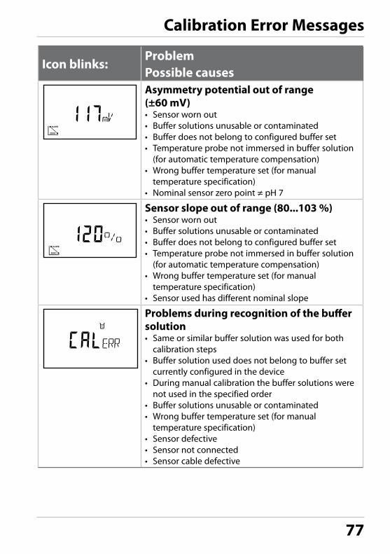
Calibration Error Messages
Icon blinks:Problem Possible causesAsymmetry potential out of range (±60 mV)• Sensor worn out• Buffer solutions unusable or contaminated• Buffer does not belong to configured buffer set• Temperature probe not immersed in buffer solution
(for automatic temperature compensation)• Wrong buffer temperature set (for manual
temperature specification)• Nominal sensor zero point ≠ pH 7
Sensor slope out of range (80...103 %)• Sensor worn out• Buffer solutions unusable or contaminated• Buffer does not belong to configured buffer set• Temperature probe not immersed in buffer solution
(for automatic temperature compensation)• Wrong buffer temperature set (for manual
temperature specification)• Sensor used has different nominal slope
Problems during recognition of the buffer solution• Same or similar buffer solution was used for both
calibration steps• Buffer solution used does not belong to buffer set
currently configured in the device• During manual calibration the buffer solutions were
not used in the specified order• Buffer solutions unusable or contaminated• Wrong buffer temperature set (for manual
temperature specification)• Sensor defective• Sensor not connected• Sensor cable defective

78
Calibration Error Messages
Icon blinks:Problem Possible causesCalibration was canceled after approx. 2 minutes because the sensor drift was too large.• Sensor defective• Sensor dirty• No electrolyte in the sensor• Sensor cable insufficiently shielded or defective• Strong electric fields influence the measurement• Major temperature fluctuation of the buffer solution• No buffer solution or extremely diluted

79
active
as configured (Last/Fix or Last/Off )
Operating status
Out
1
Out
2
Rela
y 1
limit
val
ueA
larm
co
ntac
tCl
eani
ng
cont
act
Tim
eout
Measure
Cal Info (cal) 0000 20 s
Error Info (conf ) 0000 20 s
Calibration (cal) 1100
Temp adjustment (cal) 1015
Product calibration (cal) 1105
Configuration (conf ) 1200 20 min
Sensor monitor(conf ) 2222 20 min
Current source 1(conf) 5555 20 min
Current source 2(conf) 5556 20 min
Rinsing function
Operating States

80
(Sensocheck must have been activated during configuration.)
The smiley in the display (Sensoface) alerts to sensor problems (defec-tive sensor, defective cable, maintenance required). The permitted calibration ranges and the conditions for a friendly, neutral, or sad Sensoface are summarized in the following table. Additional icons refer to the error cause.
SensocheckContinuously monitors the sensor and leads for short circuits or open circuits. Critical values make the Sensoface “sad” and the correspond-ing icon blinks:
The Sensocheck message is also output as error message Err 33. The alarm contact is active, the red LED is lit, output current 1 is set to 22 mA (when configured correspondingly). Sensocheck can be switched off during configuration (then Sensoface is also dis-abled). Exception: After a calibration a smiley is always displayed for confirmation.
NoticeThe worsening of a Sensoface criterion leads to the devaluation of the Sensoface indicator (Smiley becomes “sad”). An improvement of the Sensoface indicator can only take place after calibration or removal of the sensor defect.
Sensoface
81
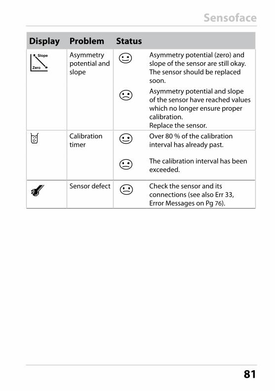
Sensoface
Display Problem StatusAsymmetry potential and slope
Asymmetry potential (zero) and slope of the sensor are still okay. The sensor should be replaced soon.Asymmetry potential and slope of the sensor have reached values which no longer ensure proper calibration. Replace the sensor.
Calibration timer
Over 80 % of the calibration interval has already past.
The calibration interval has been exceeded.
Sensor defect Check the sensor and its connections (see also Err 33, Error Messages on Pg 76).

82

83
Appendix
Devices Order No.
Stratos Eco 2405 pH 2405 pH
Mounting Accessories
Pipe-mount kit ZU 0274
Panel-mount kit ZU 0275
Protective hood ZU 0276
Product Line and Accessories
For more information concerning our sensors and fittings product line, please refer to our website:www.knick.de

84
SpecificationspH/mV input Input for pH or ORP sensors
Measuring range –1500 ... +1500 mV
Display range pH value –2.00 ... 16.00
ORP –1999 ... +1999 mV
Glass electrode input1)
Input resistance > 0.5 x 10¹² ohms
Input current < 2 x 10-12 A
Reference electrode input1)
Input resistance > 1 x 10¹⁰ ohms
Input current < 1 x 10⁻¹⁰ A
Meas. error1,2,3)
pH value < 0.02 TC: 0.002 pH/K (display)
mV value < 1 mV TC: 0.1 mV/K
pH sensor standardization * pH calibration
Operating modes BUF Calibration with automatic buffer recognitionCalimatic:
Buffer sets -01- Knick / Mettler-Toledo2.00/4.01/7.00/9.21
-02- Merck/Riedel de Haen2.00/4.00/7.00/9.00/12.00
-03- Ciba (94)2.06/4.00/7.00/10.00
-04- NIST technical1.68/4.00/7.00/10.01/12.46
-05- NIST standard1.680/4.008/6.865/9.184
-06- HACH4.00/7.00/10.01
-07- WTW technical buffers2.00/4.01/7.00/10.00
-08- Hamilton4.01/7.00/10.01
85
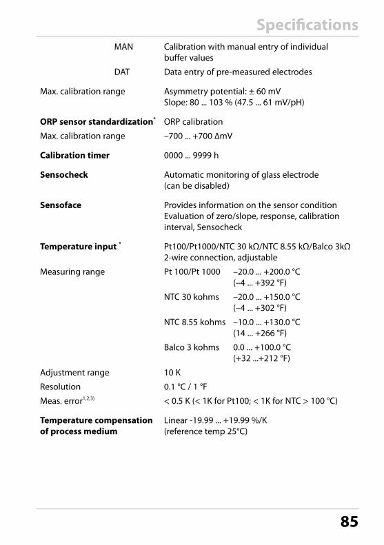
SpecificationsMAN Calibration with manual entry of individual
buffer values
DAT Data entry of pre-measured electrodes
Max. calibration range Asymmetry potential: ± 60 mVSlope: 80 ... 103 % (47.5 ... 61 mV/pH)
ORP sensor standardization* ORP calibration
Max. calibration range –700 ... +700 ∆mV
Calibration timer 0000 ... 9999 h
Sensocheck Automatic monitoring of glass electrode (can be disabled)
Sensoface Provides information on the sensor conditionEvaluation of zero/slope, response, calibration interval, Sensocheck
Temperature input * Pt100/Pt1000/NTC 30 kΩ/NTC 8.55 kΩ/Balco 3kΩ2-wire connection, adjustable
Measuring range Pt 100/Pt 1000 –20.0 ... +200.0 °C(–4 ... +392 °F)
NTC 30 kohms –20.0 ... +150.0 °C(–4 ... +302 °F)
NTC 8.55 kohms –10.0 ... +130.0 °C(14 ... +266 °F)
Balco 3 kohms 0.0 ... +100.0 °C (+32 ...+212 °F)
Adjustment range 10 K
Resolution 0.1 °C / 1 °F
Meas. error1,2,3) < 0.5 K (< 1K for Pt100; < 1K for NTC > 100 °C)
Temperature compensation of process medium
Linear -19.99 ... +19.99 %/K(reference temp 25°C)

86
Output 1 0/4 ... 20 mA, max. 10 V, floating (galvanically connected to output 2)
Process variable* pH or mV value
Overrange * 22 mA in the case of error messages
Output filter * Low-pass, filter time constant 0 ... 120 s
Measurement error 1) < 0.3% current value + 0.05 mA
Start/end of scale Configurable within the measuring range for pH or mV
Admissible span pH 2.00 ... 18.00 / 200 ... 3000 mV
Output 2 0/4 ... 20 mA, max. 10 V, floating (galvanically connected to output 1)
Process variable Temperature
Overrange * 22 mA in case of temp error messages
Output filter * Low-pass, filter time constant 0 ... 120 s
Measurement error 1) < 0.3% current value + 0.05 mA
Start/end of scale * –20 ... 200 °C / –4 ... 392 °F
Admissible span 20 ... 220 K / 36 ... 396 °F
Alarm contact Relay contact, floating
Contact ratings AC< 250 V / < 3 A / < 750 VA DC< 30 V / < 3 A / < 90 W
Contact response N/C (fail-safe type)
Alarm delay 10 s
Limit values Output via relay contact
Contact ratings AC< 250 V / < 3 A / < 750 VADC< 30 V / < 3 A / < 90 W
Contact response* N/C or N/O
Delay * 0000 ... 9999 s
Switching points* As desired within range
Hysteresis* 00.00 ... 05.00 pH / 0000 ... 0500 mV
Specifications

87
Cleaning function Relay contact, floating, for controlling a simple rinsing system or an automatic cleaning system
Contact ratings AC< 250 V / < 3 A / < 750 VADC< 30 V / < 3 A / < 90 W
Contact response N/C or N/O
Rinse interval 000.0 ... 999.9 h(000.0 h = cleaning function switched off )
Rinse duration 0000 ... 1999 s
Display LC display, 7-segment with icons
Main display Character height 17 mm, unit symbols 10 mm
Secondary display Character height 10 mm, unit symbols 7 mm
Sensoface 3 status indicators (friendly, neutral, sad face)
Mode indication 4 mode indicators “meas“, “cal“, “alarm“, “config“Further icons for configuration and messages
Alarm indication Red LED in case of alarm
Keypad 5 keys: [cal] [conf ] [] [] [enter]
Service functions
Current source Current specifiable for output 1 and 2 (00.00 ... 22.00 mA)
Device self-test Automatic memory test (RAM, FLASH, EEPROM)
Display test Display of all segments
Last Error Display of last error occurred
Sensor monitor Display of direct, uncorrected sensor signal
Data retention Parameters and calibration data > 10 years (EEPROM)
Protection against electric shock
Safe electrical isolation of all extra-low-voltage circuits against mains by double insulation to EN 61010-1
Specifications

88
Power supply 24 (–15%) ... 230 V AC/DC (+10%); approx. 5 VA, 2.5 W, AC: 45 ... 65 HzOvervoltage category II, protection class II
Nominal operating conditions
Ambient temperature –20 ... +55 °C
Transport/Storage temp –20 ... +70 °C
Relative humidity 10…95 % not condensing, maximum operating height 2000 m
Power supply 24 (–15%) ... 230 V AC/DC (+10%)
Frequency for AC 45 ... 65 Hz
EMC EN 61326-1, EN 61326-2-3
Emitted interference Class B (residential area) Class A for mains > 60 V DC
Immunity to interference Industry
Explosion protection
FM NI Class I Div 2 Group A, B, C & D, T4 Ta = 55 °C; Type 2 NI Class I Zone 2 Group IIC, T4 Ta = 55°C; Type 2
CSA Class I Div 2 Groups A, B, C and D, T4 Ex nA IIC T4
Enclosure Molded enclosure made of PBT, glass bead reinforced
Color Black
Mounting • Wall mounting• Pipe mounting: Ø 40 ... 60 mm 30 ... 45 mm• Panel mounting,
cutout to DIN 43 700, sealed against panel
Dimensions H 144 mm, W 144 mm, D 105 mm
Ingress protection IP 65 / NEMA 4X
Cable glands 3 knockouts for cable glands M20x1.52 knockouts for NPT 1/2" or rigid metallic conduit
Specifications
89
Weight Approx.1 kg
* User-defined
1) To IEC 746 Part 1, at nominal operating conditions
2) ± 1 count
3) Plus sensor error
Specifications

90
Buffer Tables
-01- Mettler-Toledo technical buffers
°C pH0 2.03 4.01 7.12 9.52
5 2.02 4.01 7.09 9.4510 2.01 4.00 7.06 9.3815 2.00 4.00 7.04 9.3220 2.00 4.00 7.02 9.2625 2.00 4.01 7.00 9.2130 1.99 4.01 6.99 9.1635 1.99 4.02 6.98 9.1140 1.98 4.03 6.97 9.0645 1.98 4.04 6.97 9.0350 1.98 4.06 6.97 8.9955 1.98 4.08 6.98 8.9660 1.98 4.10 6.98 8.9365 1.99 4.13 6.99 8.9070 1.99 4.16 7.00 8.8875 2.00 4.19 7.02 8.8580 2.00 4.22 7.04 8.8385 2.00 4.26 7.06 8.8190 2.00 4.30 7.09 8.7995 2.00 4.35 7.12 8.77

91
Buffer Tables
-02- Knick CaliMat (Merck Titrisols, Riedel-de-Haen Fixanals)
°C pHOrder No. CS-P0200A/... CS-P0400A/... CS-P0700A/... CS-P0900A/... CS-P1200A/...
0 2.01 4.05 7.09 9.24 12.585 2.01 4.04 7.07 9.16 12.3910 2.01 4.02 7.04 9.11 12.2615 2.00 4.01 7.02 9.05 12.1320 2.00 4.00 7.00 9.00 12.0025 2.00 4.01 6.99 8.95 11.8730 2.00 4.01 6.98 8.91 11.7535 2.00 4.01 6.96 8.88 11.6440 2.00 4.01 6.96 8.85 11.5350 2.00 4.01 6.96 8.79 11.3160 2.00 4.00 6.96 8,73 11.0970 2.00 4.00 6.96 8,70 10.8880 2.00 4.00 6.98 8,66 10.6890 2.00 4.00 7.00 8,64 10.48

92
-03-Ciba (94) buffersNominal values: 2.06, 4.00, 7.00, 10.00
°C pH0 2.04 4.00 7.10 10.30
5 2.09 4.02 7.08 10.2110 2.07 4.00 7.05 10.1415 2.08 4.00 7.02 10.0620 2.09 4.01 6.98 9.9925 2.08 4.02 6.98 9.9530 2.06 4.00 6.96 9.8935 2.06 4.01 6.95 9.8540 2.07 4.02 6.94 9.8145 2.06 4.03 6.93 9.7750 2.06 4.04 6.93 9.7355 2.05 4.05 6.91 9.6860 2.08 4.10 6.93 9.6665 2.07 * 4.10 * 6.92 * 9.61 *70 2.07 4.11 6.92 9.5775 2.04 * 4.13 * 6.92 * 9.54 *80 2.02 4.15 6.93 9.5285 2.03 * 4.17 * 6.95 * 9.47 *90 2.04 4.20 6.97 9.4395 2.05 * 4.22 * 6.99 * 9.38 *
* extrapolated
Buffer Tables
93
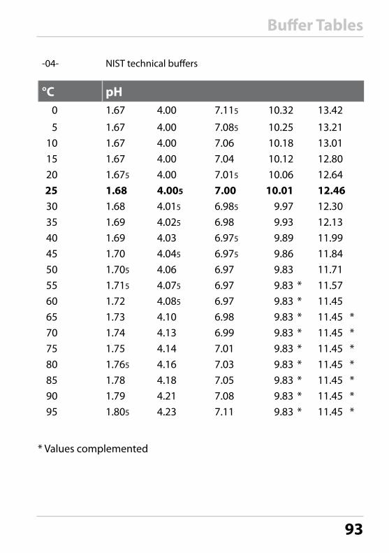
-04- NIST technical buffers
°C pH0 1.67 4.00 7.115 10.32 13.42
5 1.67 4.00 7.085 10.25 13.2110 1.67 4.00 7.06 10.18 13.0115 1.67 4.00 7.04 10.12 12.8020 1.675 4.00 7.015 10.06 12.6425 1.68 4.005 7.00 10.01 12.4630 1.68 4.015 6.985 9.97 12.3035 1.69 4.025 6.98 9.93 12.1340 1.69 4.03 6.975 9.89 11.9945 1.70 4.045 6.975 9.86 11.8450 1.705 4.06 6.97 9.83 11.7155 1.715 4.075 6.97 9.83 * 11.5760 1.72 4.085 6.97 9.83 * 11.4565 1.73 4.10 6.98 9.83 * 11.45 *70 1.74 4.13 6.99 9.83 * 11.45 *75 1.75 4.14 7.01 9.83 * 11.45 *80 1.765 4.16 7.03 9.83 * 11.45 *85 1.78 4.18 7.05 9.83 * 11.45 *90 1.79 4.21 7.08 9.83 * 11.45 *95 1.805 4.23 7.11 9.83 * 11.45 *
* Values complemented
Buffer Tables

94
-05-NIST standard buffersNIST Standard (DIN 19266 : 2000-01)
°C pH0
5 1.668 4.004 6.950 9.39210 1.670 4.001 6.922 9.33115 1.672 4.001 6.900 9.27720 1.676 4.003 6.880 9.22825 1.680 4.008 6.865 9.18430 1.685 4.015 6.853 9.14437 1.694 4.028 6.841 9.09540 1.697 4.036 6.837 9.07645 1.704 4.049 6.834 9.04650 1.712 4.064 6.833 9.01855 1.715 4.075 6.834 9.98560 1.723 4.091 6.836 8.962
70 1.743 4.126 6.845 8.921
80 1.766 4.164 6.859 8.885
90 1.792 4.205 6.877 8.85095 1.806 4.227 6.886 8.833
Please note:The actual pH values of the individual batches of the reference materials are docu-mented in a certificate of an accredited laboratory. This certificate is supplied with the respective buffers. Only these pH(S) values shall be used as standard values for the secondary reference buffer materials. Correspondingly, this standard does not include a table with standard pH values for practical use. The table above only provides examples of pH(PS) values for orientation.
Buffer Tables

95
-06-HACH buffersNominal values: 4.01, 7.00, 10.01
°C pH0 4.00 7.14 10.30
5 4.00 7.10 10.2310 4.00 7.04 10.1115 4.00 7.04 10.1120 4.00 7.02 10.0525 4.01 7.00 10.0030 4.01 6.99 9.9635 4.02 6.98 9.9240 4.03 6.98 9.8845 4.05 6.98 9.8550 4.06 6.98 9.8255 4.07 6.98 9.7960 4.09 6.99 9.7665 4.09 * 6.99 * 9.76 *70 4.09 * 6.99 * 9.76 *75 4.09 * 6.99 * 9.76 *80 4.09 * 6.99 * 9.76 *85 4.09 * 6.99 * 9.76 *90 4.09 * 6.99 * 9.76 *95 4.09 * 6.99 * 9.76 *
* Values complemented
Buffer Tables

96
-07- WTW buffers
°C pH0 2.03 4.01 7.12 10.65
5 2.02 4.01 7.09 10.5210 2.01 4.00 7.06 10.3915 2.00 4.00 7.04 10.2620 2.00 4.00 7.02 10.1325 2.00 4.01 7.00 10.0030 1.99 4.01 6.99 9.8737 1.99 4.02 6.98 9.7440 1.98 4.03 6.97 9.6145 1.98 4.04 6.97 9.4850 1.98 4.06 6.97 9.3555 1.98 4.08 6.9860 1.98 4.10 6.9865 1.99 4.13 6.9970 2.00 4.16 7.0075 2.00 4.19 7.0280 2.00 4.22 7.0485 2.00 4.26 7.0690 2.00 4.30 7.0995 2.00 4.35 7.12
Buffer Tables

97
-08- Hamilton Duracal buffers
°C pH0 4.01 7.12 10.19
5 4.01 7.09 10.1910 4.00 7.06 10.1515 4.00 7.04 10.1120 4.00 7.02 10.0625 4.01 7.00 10.0130 4.01 6.99 9.9735 4.02 6.98 9.9240 4.03 6.97 9.8645 4.04 6.97 9.8350 4.06 6.97 9.7955 4.08 * 6.98 * 9.77 *60 4.10 * 6.98 * 9.75 *65 4.13 * 6.99 * 9.74 *70 4.16 * 7.00 * 9.73 *75 4.19 * 7.02 * 9.73 *80 4.22 * 7.04 * 9.73 *85 4.26 * 7.06 * 9.74 *90 4.30 * 7.09 * 9.75 *95 4.35 * 7.09 * 9.75 *
* extrapolated
The values above 50°C are not traceable to NIST.
Buffer Tables

98
GlossaryAsymmetry potential
The voltage which a pH sensor provides at a pH of 7. The asymmetry potential is different for each sensor and changes with age and wear.
Buffer set Contains selected buffer solutions which can be used for automatic calibration with the Calimatic. The buffer set must be selected prior to the first calibration.
Buffer solution
Solution with an exactly defined pH value for calibrating a pH meter.
Calibration Adjustment of the pH meter to the current sensor characteristics. The asymmetry potential and slope are adjusted. Either a one- or two-point calibration can be carried out. With one-point calibration only the asymmetry potential (zero point) is adjusted.
Calimatic Automatic buffer recognition. Before the first calibration, the buffer set used must be activated once. The patented Calimatic then automatically recognizes the buffer solutions used during cali-bration.
Combination electrode
Combination of glass and reference electrode in one body.
GainCheck Device self-test which runs automatically in the background at fixed intervals. The memory and measured-value transmission are checked. You can also start the GainCheck manually. Then a display test is also conducted and the software version displayed.

99
GlossaryOne-point calibration
Calibration with which only the asymmetry poten-tial (zero point) is taken into account. The previous slope value is retained. Only one buffer solution is required for a one-point calibration.
Passcode Preset four-digit number to select certain functions.
pH electrode system
A pH electrode system (pH sensor) consists of a glass and a reference electrode. If they are com-bined in one body, they are referred to as combina-tion electrode.
Response time
Time from the start of a calibration step to the stabilization of the sensor potential.
Sensocheck Sensocheck continuously monitors the glass and reference electrodes. The resulting information is indicated by the Sensoface smileys. Sensocheck can be switched off.
Sensoface Provides information on the sensor condition. The zero point, slope, and response time are evalu-ated. In addition, the Sensocheck information is indicated.
Sensor slope Is indicated in % of the theoretical slope (59.2 mV/pH at 25 °C). The sensor slope is different for each sensor and changes with age and wear.
Sensor zero point
See asymmetry potential

100
GlossaryTwo-point calibration
Calibration with which the sensor asymmetry potential (zero point) and slope are determined. Two buffer solutions are required for two-point calibration.
Zero See asymmetry potential

101

102
• The equipment shall be installed and protected from mechanical impact and ultraviolet (UV) sources.
• Clean only with a moistened antistatic cloth as potential electro-static hazard may exist. Service equipment only with conductive clothing, footwear and personal grounding devices to prevent electrostatic accumulation.
• Internal grounding provisions shall be provided for field wiring. Bonding between conduit shall be provided during installation, and all exposed non-current carrying metallic parts shall be bonded and grounded.
• Installation in a ClassI, Division 2 or Class I, Zone 2 hazardous location shall be in accordance with the Canadian Electrical Code (CEC Part 1) Section 18 Division 2 wiring methods.
• The equipment shall have a switch or circuit breaker in the build-ing installation (that is in close proximity to the equipment) that is marked as the disconnect switch.
• The enclosure Type 2 is only for indoor use.• The mains supply voltage fluctuations should not exceed
-15/+10 percent of the nominal supply voltage.• The device shall not be used in a manner not specified by this
manual.
CAUTION!Clean only with antistatic moistened cloth.
CAUTION!Substitution of components may impair suitability for hazardous locations.
Warnings and Notes to Ensure Safe Operation
WARNING!Do not disconnect equipment unless power has been switched off.
Approvals – Canada
103
OBSERVE THE SPECIFICATIONS OF THE CONTROL DRAWING!
CAUTION!Use supply wires suitable for 30 °C above ambient and rated at least 250 V.
CAUTION!Use signal wires suitable for at least 250V.
Approvals – Canada

104
Approvals – CanadaCSA Control Drawing

105
Approvals – Canada

106
Index22 mA signal for error message 41, 47
AAccessories 83Alarm contact 53Alarm setings 29, 52Approvals 102Assembly 10
BBuffer set selection 51Buffer tables 90
CCalibration 62
Automatic calibration 64Calibration mode selection 50Cal timer interval 50Data entry of pre-measured electrodes 68Error messages 77Manual calibration 66ORP calibration 70Product calibration 69
Calimatic 64Cal Info 73“Clean” contact 56Configuration 30
Menu structure 31Configuration: Alarm settings 52Configuration: Calibration mode 50Configuration: Limit function 54Configuration: Output 1 34
Output current during Error and HOLD 40Output current range 36Process variable (pH/ORP) 34Time constant of output filter 38
Configuration: Output 2 42Output current 42Output current during HOLD 46

107
IndexTemperature 42Temperature error 46Time constant of output filter 44
Configuration: Rinsing probes 56Configuration: Temperature compensation 48Connection 14CSA Control Drawing 104CSA warnings and notes 102Current start / end 37, 43
DDevice self-test 27Diagnostics functions 73
Display of calibration data 73Display of last error message 73Display of output currents 73Display of sensor potential 73Specifying the output current 74
Display 25Disposal 2Division 2 wiring 15Documentation 8
EError Info 73Error messages 75
Display of last error message 73Explosion protection 88
FFactory settings of parameters 58Front panel 24
GGlossary 98
HHOLD mode 28
Output signal during HOLD 41, 47Hysteresis 55

108
IndexIInstallation 14Intended use 7
KKeypad 26
MMeasurement 72Mounting plan 11
OOperating states 79ORP measurement
Calibration 70Wiring example 21
Output filter 38, 44Overview 9Overview of configuration steps 32
PPackage contents 10Panel mounting 13Panel-mount kit 13Parameters
Factory settings 58Individual settings 60
Passcodes 110Pipe mounting 12Pipe-mount kit 12Product calibration 69Product line 83Protective hood 12Protective wiring 22
QQuickstart guides 8
109
IndexRRelay 54, 56Relay contacts 22Rinse contact 56Rinsing interval 57Rinsing probes 56Rinsing system 57
SSafety information 5, 102Self-test 27Sensocheck 27, 52, 80
Configuration 53Sensoface 27, 80Sensor connection
VP cable 16Sensor monitor 73Short instructions 8Specifications 84
TTemperature compensation 48Temperature measurement, configuration 43Temperature probe adjustment 72Terminal assignments 14Time constant of output filter 39, 45Trademarks 7
UUser interface 24
VVP cable connection 16
WWiring examples
ORP measurement 21pH measurement 18, 19, 20VP cable 16VP connection 19, 20

PasscodesCalibration
Key + passcode Menu item Pagecal + 0000cal + 1100cal + 1105cal + 1015
Configuration
Key + passcode Menu item Pageconf + 0000conf + 1200conf + 2222conf + 5555conf + 5556conf + + 4321
TA-194.132-KNE03 20180102 Software version: 2.x
CAL info (display of zero,slope) 73
Calibration (with buffer solution) 64Product calibration 69Temp probe adjustment 72
Error info (display of last error, erase) 73
Configuration 30Sensor monitor (sensor potential) 73Current source 1 (specify output current) 74Current source 2 (specify output current) 74
Factory setting 58