Embed Size (px)
Citation preview
Commissioning Manual308011En, Ed.2/Rev.BJune 2008
Commissioning Manual
www.rosemount-tg.com
Product Discontinued

www.rosemount-tg.com
Commissioning manualSecond edition
Revision B
Copyright © June 2008Rosemount Tank Radar AB

www.rosemount-tg.com
Copyright © June 2008
Rosemount Tank Radar ABThe contents, descriptions and specifications within this manual is subject to change without notice. Rosemount Tank Radar AB accepts no responsibility for any errors that may appear in this manual.
Trademarks
Rosemount, and the Rosemount logotype are registered trademarks of Rosemount Inc.
TankRadar is a registered trademark of Rosemount Tank Radar AB.
HART is a registered trademark of HART Communication Foundation
Spare Parts
Any substitution of non-recognized spare parts may jeopardize safety. Repair, e.g. substitution of components etc., may also jeopardize safety and is under no circumstances allowed.
Rosemount Tank Radar AB will not take any responsibility for faults, accidents, etc. caused by non-recognized spare parts or any repair which is not made by Rosemount Tank Radar AB.
Specific FCC Requirements (USA only)
Rosemount TankRadar Rex generates and uses radio frequency energy. If it is not installed and used properly, that is, in strict accordance with the manufacturer´s instructions, it may violate FCC regulations on radio frequency emission.
Rosemount TankRadar Rex has been FCC certified under test conditions which assume a metallic tank. Installation on a non-metallic tank is not certified, and is not allowed.
The FCC certificate for Rosemount TankRadar Rex requires that the tank is closed as far as emitted radio energy is concerned. Tanks with open manholes, external-floating-roof tanks without still-pipes etc. are not covered by the certificate.
Rosemount TankRadar RexTable of Contents
Commissioning Manual308011En, Ed.2/Rev.BJune 2008
Contents1. CHECKS AND ADJUSTMENTS. . . . . . . . . . . . . . . . . . . . . . 1-1
1.1 GENERAL . . . . . . . . . . . . . . . . . . . . . . . . . . . . . . . . . . . . . . . . . . . . . . .1-1
1.2 PREPARATIONS . . . . . . . . . . . . . . . . . . . . . . . . . . . . . . . . . . . . . . . . .1-1
1.3 TANK INTERIOR CONDITIONS . . . . . . . . . . . . . . . . . . . . . . . . . . . . . .1-2
1.4 SYSTEM COMPOSITION . . . . . . . . . . . . . . . . . . . . . . . . . . . . . . . . . . .1-2
1.5 FCU CHECKLIST . . . . . . . . . . . . . . . . . . . . . . . . . . . . . . . . . . . . . . . . .1-21.5.1 FCU information . . . . . . . . . . . . . . . . . . . . . . . . . . . . . . . .1-21.5.2 Visual check . . . . . . . . . . . . . . . . . . . . . . . . . . . . . . . . . . .1-21.5.3 Electrical check . . . . . . . . . . . . . . . . . . . . . . . . . . . . . . . .1-31.5.4 Field bus check . . . . . . . . . . . . . . . . . . . . . . . . . . . . . . . .1-31.5.5 Group bus check . . . . . . . . . . . . . . . . . . . . . . . . . . . . . . .1-31.5.6 Software . . . . . . . . . . . . . . . . . . . . . . . . . . . . . . . . . . . . . .1-3
1.6 FBM 2180 CHECKLIST . . . . . . . . . . . . . . . . . . . . . . . . . . . . . . . . . . . .1-41.6.1 FBM information . . . . . . . . . . . . . . . . . . . . . . . . . . . . . . . .1-41.6.2 Visual check . . . . . . . . . . . . . . . . . . . . . . . . . . . . . . . . . . .1-41.6.3 Field bus check . . . . . . . . . . . . . . . . . . . . . . . . . . . . . . . .1-41.6.4 Power supply . . . . . . . . . . . . . . . . . . . . . . . . . . . . . . . . . .1-4
1.7 COMMUNICATION OVERVIEW . . . . . . . . . . . . . . . . . . . . . . . . . . . . .1-5
1.8 RTG 3900 - GENERAL INFORMATION . . . . . . . . . . . . . . . . . . . . . . . .1-61.8.1 Tank Information . . . . . . . . . . . . . . . . . . . . . . . . . . . . . . . .1-61.8.2 Electrical check . . . . . . . . . . . . . . . . . . . . . . . . . . . . . . . .1-61.8.3 Tank measurements . . . . . . . . . . . . . . . . . . . . . . . . . . . . .1-7
1.9 RTG 3920 . . . . . . . . . . . . . . . . . . . . . . . . . . . . . . . . . . . . . . . . . . . . . . .1-81.9.1 Tank Information . . . . . . . . . . . . . . . . . . . . . . . . . . . . . . . .1-81.9.2 Visual check . . . . . . . . . . . . . . . . . . . . . . . . . . . . . . . . . . .1-81.9.3 Tank measurements . . . . . . . . . . . . . . . . . . . . . . . . . . . . .1-81.9.4 Free space requirements . . . . . . . . . . . . . . . . . . . . . . . . .1-8
1.10 RTG 3930 . . . . . . . . . . . . . . . . . . . . . . . . . . . . . . . . . . . . . . . . . . . . . .1-101.10.1 Tank Information . . . . . . . . . . . . . . . . . . . . . . . . . . . . . . .1-101.10.2 Visual check . . . . . . . . . . . . . . . . . . . . . . . . . . . . . . . . . .1-101.10.3 Tank measurements . . . . . . . . . . . . . . . . . . . . . . . . . . . .1-101.10.4 Free space requirements . . . . . . . . . . . . . . . . . . . . . . . . 1-11
TOC-1
Rosemount TankRadar RexTable of Contents
Commissioning Manual308011En, Ed.2/Rev.B
June 2008
1.11 RTG 3950 . . . . . . . . . . . . . . . . . . . . . . . . . . . . . . . . . . . . . . . . . . . . . .1-121.11.1 Tank Information . . . . . . . . . . . . . . . . . . . . . . . . . . . . . . .1-121.11.2 Visual check . . . . . . . . . . . . . . . . . . . . . . . . . . . . . . . . . .1-121.11.3 Still-Pipe Requirements . . . . . . . . . . . . . . . . . . . . . . . . .1-131.11.4 Free space requirements . . . . . . . . . . . . . . . . . . . . . . . .1-13
1.12 RTG 3960 . . . . . . . . . . . . . . . . . . . . . . . . . . . . . . . . . . . . . . . . . . . . . .1-151.12.1 Tank Information . . . . . . . . . . . . . . . . . . . . . . . . . . . . . . .1-151.12.2 Visual check . . . . . . . . . . . . . . . . . . . . . . . . . . . . . . . . . .1-161.12.3 Still-Pipe . . . . . . . . . . . . . . . . . . . . . . . . . . . . . . . . . . . . .1-161.12.4 Verification Pins . . . . . . . . . . . . . . . . . . . . . . . . . . . . . . .1-17
1.13 REX CONFIGURATION . . . . . . . . . . . . . . . . . . . . . . . . . . . . . . . . . . .1-191.13.1 Tank Information . . . . . . . . . . . . . . . . . . . . . . . . . . . . . . .1-191.13.2 Tank Distances and RTG Geometry . . . . . . . . . . . . . . . .1-191.13.3 Rex configuration . . . . . . . . . . . . . . . . . . . . . . . . . . . . . .1-201.13.4 Input Register parameters . . . . . . . . . . . . . . . . . . . . . . .1-211.13.5 Calibration . . . . . . . . . . . . . . . . . . . . . . . . . . . . . . . . . . .1-22
1.14 DATA ACQUISITION UNIT . . . . . . . . . . . . . . . . . . . . . . . . . . . . . . . . .1-231.14.1 Tank Information . . . . . . . . . . . . . . . . . . . . . . . . . . . . . . .1-231.14.2 Distance . . . . . . . . . . . . . . . . . . . . . . . . . . . . . . . . . . . . .1-231.14.3 Cable and Junction box . . . . . . . . . . . . . . . . . . . . . . . . .1-231.14.4 Electrical check . . . . . . . . . . . . . . . . . . . . . . . . . . . . . . .1-231.14.5 Temperature . . . . . . . . . . . . . . . . . . . . . . . . . . . . . . . . . .1-231.14.6 Software . . . . . . . . . . . . . . . . . . . . . . . . . . . . . . . . . . . . .1-24
1.15 DAU CONFIGURATION . . . . . . . . . . . . . . . . . . . . . . . . . . . . . . . . . . .1-241.15.1 Tank Information . . . . . . . . . . . . . . . . . . . . . . . . . . . . . . .1-241.15.2 Temperature Check . . . . . . . . . . . . . . . . . . . . . . . . . . . .1-241.15.3 Current inputs . . . . . . . . . . . . . . . . . . . . . . . . . . . . . . . . .1-241.15.4 Display . . . . . . . . . . . . . . . . . . . . . . . . . . . . . . . . . . . . . .1-24
1.16 OPERATOR SOFTWARE . . . . . . . . . . . . . . . . . . . . . . . . . . . . . . . . .1-251.16.1 TankMaster WinOpi . . . . . . . . . . . . . . . . . . . . . . . . . . . .1-251.16.2 Back-up . . . . . . . . . . . . . . . . . . . . . . . . . . . . . . . . . . . . .1-25
INDEX . . . . . . . . . . . . . . . . . . . . . . . . . . . . . . . . . . . . . . . . INDEX-1
TOC-2
Rosemount TankRadar RexChapter 1 Checks and Adjustments
Commissioning Manual308011En, Ed.2/Rev.BJune 2008
1. Checks and Adjustments
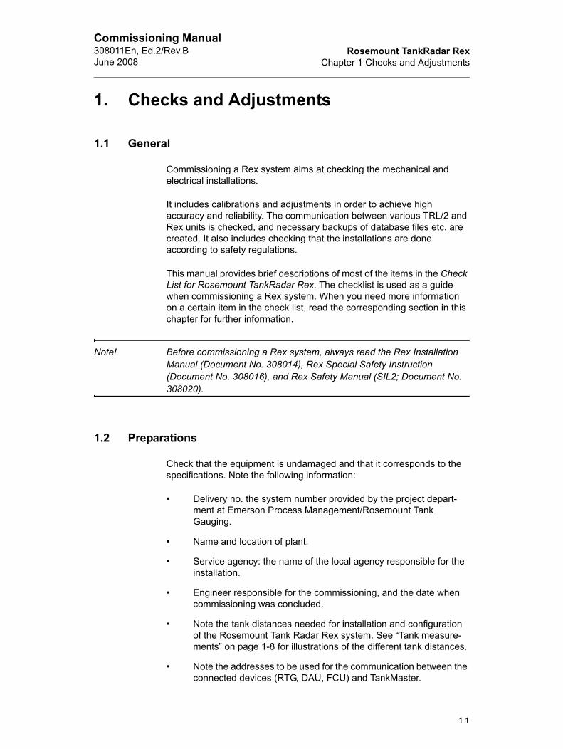
1.1 General
Commissioning a Rex system aims at checking the mechanical and electrical installations.
It includes calibrations and adjustments in order to achieve high accuracy and reliability. The communication between various TRL/2 and Rex units is checked, and necessary backups of database files etc. are created. It also includes checking that the installations are done according to safety regulations.
This manual provides brief descriptions of most of the items in the Check List for Rosemount TankRadar Rex. The checklist is used as a guide when commissioning a Rex system. When you need more information on a certain item in the check list, read the corresponding section in this chapter for further information.
Note! Before commissioning a Rex system, always read the Rex Installation Manual (Document No. 308014), Rex Special Safety Instruction (Document No. 308016), and Rex Safety Manual (SIL2; Document No. 308020).
1.2 Preparations
Check that the equipment is undamaged and that it corresponds to the specifications. Note the following information:
• Delivery no. the system number provided by the project depart-ment at Emerson Process Management/Rosemount Tank Gauging.
• Name and location of plant.
• Service agency: the name of the local agency responsible for the installation.
• Engineer responsible for the commissioning, and the date when commissioning was concluded.
• Note the tank distances needed for installation and configuration of the Rosemount Tank Radar Rex system. See “Tank measure-ments” on page 1-8 for illustrations of the different tank distances.
• Note the addresses to be used for the communication between the connected devices (RTG, DAU, FCU) and TankMaster.
1-1
Rosemount TankRadar RexChapter 1 Checks and Adjustments
Commissioning Manual308011En, Ed.2/Rev.B
June 2008
• Check that the correct hardware parts are installed.
• Make sure that you bring appropriate tools and instruments.
• Install TankMaster.
1.3 Tank Interior Conditions
Look for objects which may produce disturbing echoes like girders, heating coils or agitators. Disturbing objects can severely affect the accuracy of the measurements.
1.4 System Composition
Enter the following information about the system:
• Number of tanks.
• System Master. There may be several units acting as master at different occasions. The system is supervised by TankMaster (WinOpi). A portable service PC may temporarily be connected to an FCU when system service is required (WinSetup). A host com-puter can be connected to an FCU or to the TankMaster PC in order to further process measured data (level, temperature, pres-sure etc.).
• The number of FCUs, FBMs, RTGs and DAUs.
1.5 FCU checklist
1.5.1 FCU information
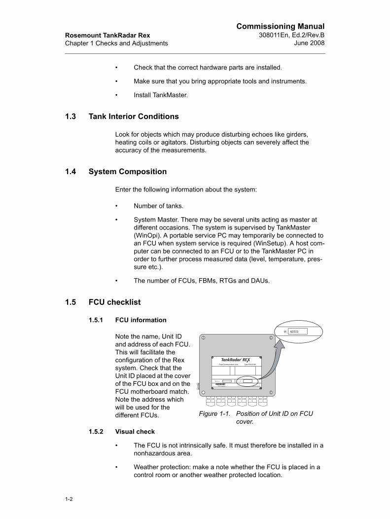
Note the name, Unit ID and address of each FCU. This will facilitate the configuration of the Rex system. Check that the Unit ID placed at the cover of the FCU box and on the FCU motherboard match. Note the address which will be used for the different FCUs.
1.5.2 Visual check
• The FCU is not intrinsically safe. It must therefore be installed in a nonhazardous area.
• Weather protection: make a note whether the FCU is placed in a control room or another weather protected location.
Figure 1-1. Position of Unit ID on FCU cover.
1-2
Rosemount TankRadar RexChapter 1 Checks and Adjustments
Commissioning Manual308011En, Ed.2/Rev.BJune 2008
1.5.3 Electrical check
• Power supply. Check that the switch inside the FCU box is set to the correct value. 230 V is the default value. If 115 V is used, the box on the nameplate "Mark box if re-wired for 115 VAC" shall be marked.
• Grounding: if there is no protective ground in the mains supply cable, the FCU should be externally grounded via the ground con-nection at the outside of the FCU box.
1.5.4 Field bus check
• Use a shielded twisted pair cable with an area of at least 0.50 mm2 for the TRL/2 bus.
• Shielded cables are required in order to avoid crosstalk if the cables run alongside and also to avoid other disturbances. The field bus shield should be connected to ground at the FCU only. Contact Emerson Process Management/Rosemount Tank Gauging for further instructions.
• Note the distance if there are two fieldbuses running in parallel.
1.5.5 Group bus check
• Note the number of group buses that are used. The FCU can be configured with two, three or four group bus ports.
• Note whether the group bus communicates via the RS-232C or the TRL/2 bus interface. By replacing the FCM board with an FCI board, RS-485 communication can also be used.
1.5.6 Software
• Note if redundant FCUs are used.
• Note the FCU program version.
To view the FCU program version:
1 Select the FCU icon in the TankMaster WinSetup workspace.
2 Click the right mouse button and choose the Properties option.
3 Select the Communication tab.
1-3
Rosemount TankRadar RexChapter 1 Checks and Adjustments
Commissioning Manual308011En, Ed.2/Rev.B
June 2008
1.6 FBM 2180 checklist
1.6.1 FBM information
• Note the name and version of each FBM.
1.6.2 Visual check
• Note if the FBM is installed outdoors or in the control room.
• Check if there is anything in the surroundings which may disturb the communication such as electromagnetic fields like radiators, big motors and transformers.
1.6.3 Field bus check
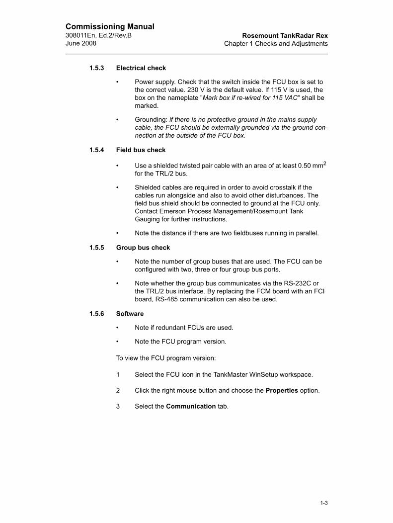
• Check that the TRL/2 bus is connected to socket 2 and 3. Use twisted and shielded single pair cable with minimum cross sec-tional area 0.50 mm2.
Table 1-1: Recommended wiring length
• Connect the shield to terminal 1 or 4.
• Connect ground cable to terminal 1 or 4.
1.6.4 Power supply
• Do not use external power supply when the modem is connected to the USB port. The USB interface itself supports power to the FBM 2180 modem.
Cable dimension Maximum length
AWG 20 (0.50 mm2) 3000 m
AWG 18 (0.75 mm2) 4000 m
Figure 1-2 FBM 2180
TRL/2 bus
1-4
Rosemount TankRadar RexChapter 1 Checks and Adjustments
Commissioning Manual308011En, Ed.2/Rev.BJune 2008
1.7 Communication overview
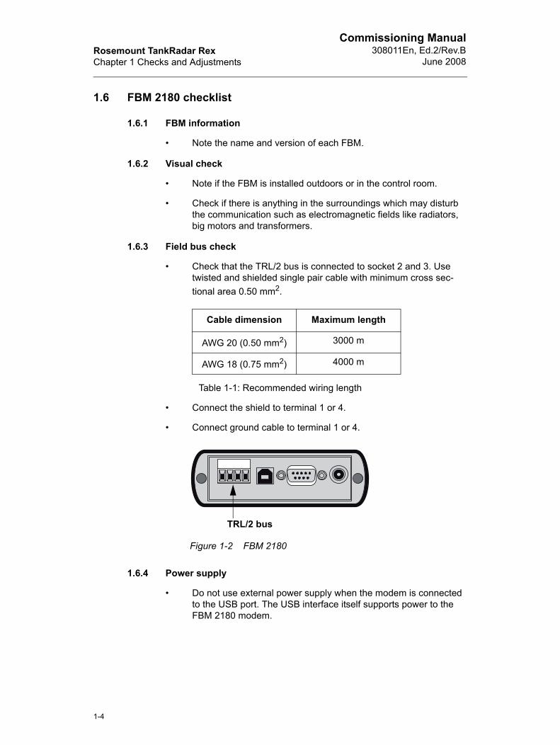
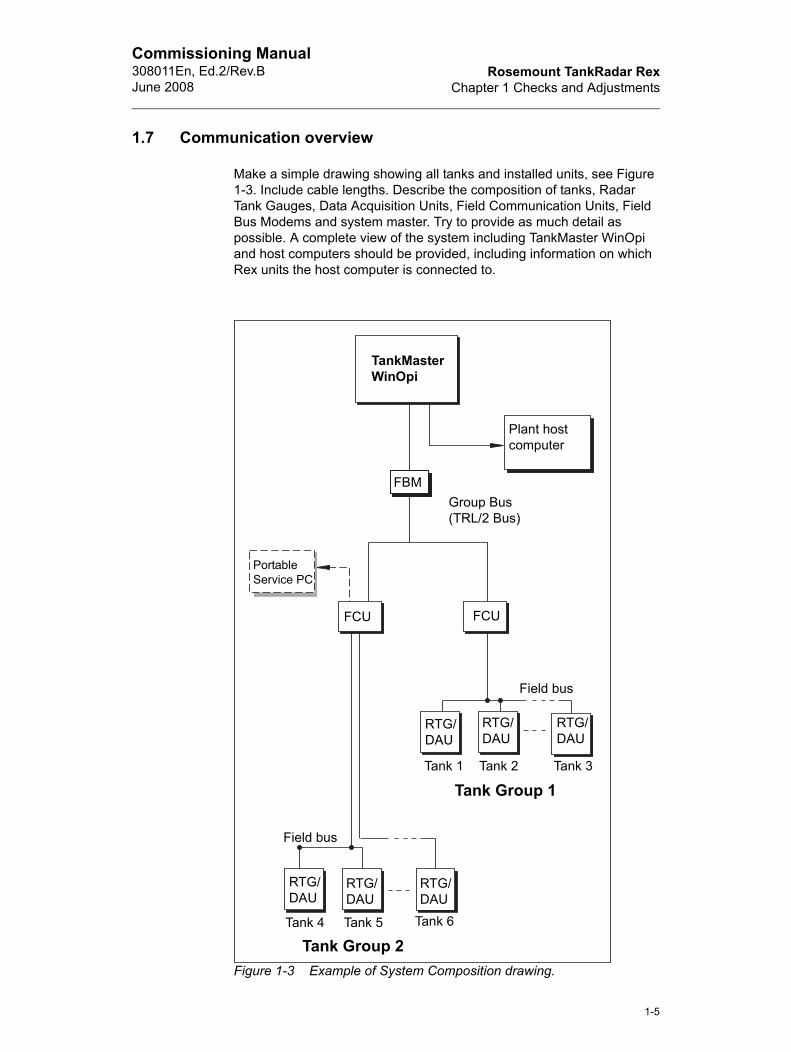
Make a simple drawing showing all tanks and installed units, see Figure 1-3. Include cable lengths. Describe the composition of tanks, Radar Tank Gauges, Data Acquisition Units, Field Communication Units, Field Bus Modems and system master. Try to provide as much detail as possible. A complete view of the system including TankMaster WinOpi and host computers should be provided, including information on which Rex units the host computer is connected to.
Figure 1-3 Example of System Composition drawing.
TankMaster WinOpi
Plant host computer
FBM
FCUFCU
Field bus
Field bus
RTG/DAU
RTG/DAU
RTG/DAU
RTG/DAU
RTG/DAU
PortableService PC
Tank 1 Tank 2 Tank 3
Tank 4 Tank 5 Tank 6
Tank Group 1
Tank Group 2
Group Bus(TRL/2 Bus)
RTG/DAU
1-5
Rosemount TankRadar RexChapter 1 Checks and Adjustments
Commissioning Manual308011En, Ed.2/Rev.B
June 2008
1.8 RTG 3900 - General information
1.8.1 Tank Information
• Tank name
• Product in tank
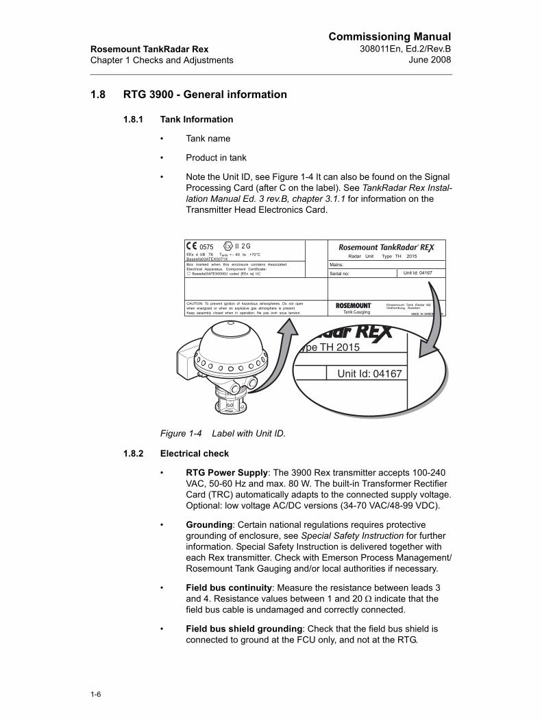
• Note the Unit ID, see Figure 1-4 It can also be found on the Signal Processing Card (after C on the label). See TankRadar Rex Instal-lation Manual Ed. 3 rev.B, chapter 3.1.1 for information on the Transmitter Head Electronics Card.
Figure 1-4 Label with Unit ID.
1.8.2 Electrical check
• RTG Power Supply: The 3900 Rex transmitter accepts 100-240 VAC, 50-60 Hz and max. 80 W. The built-in Transformer Rectifier Card (TRC) automatically adapts to the connected supply voltage.Optional: low voltage AC/DC versions (34-70 VAC/48-99 VDC).
• Grounding: Certain national regulations requires protective grounding of enclosure, see Special Safety Instruction for further information. Special Safety Instruction is delivered together with each Rex transmitter. Check with Emerson Process Management/Rosemount Tank Gauging and/or local authorities if necessary.
• Field bus continuity: Measure the resistance between leads 3 and 4. Resistance values between 1 and 20 Ω indicate that the field bus cable is undamaged and correctly connected.
• Field bus shield grounding: Check that the field bus shield is connected to ground at the FCU only, and not at the RTG.
1-6
Rosemount TankRadar RexChapter 1 Checks and Adjustments
Commissioning Manual308011En, Ed.2/Rev.BJune 2008
nce
1.8.3 Tank measurements
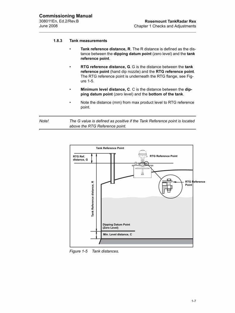
• Tank reference distance, R. The R distance is defined as the dis-tance between the dipping datum point (zero level) and the tank reference point.
• RTG reference distance, G. G is the distance between the tank reference point (hand dip nozzle) and the RTG reference point. The RTG reference point is underneath the RTG flange, see Fig-ure 1-5.
• Minimum level distance, C. C is the distance between the dip-ping datum point (zero level) and the bottom of the tank.
• Note the distance (mm) from max product level to RTG reference point.
Note! The G value is defined as positive if the Tank Reference point is located above the RTG Reference point.
Figure 1-5 Tank distances.
Tank Reference Point
RTG Reference Point
Dipping Datum Point(Zero Level)
Min. Level distance, C
RTG Ref.distance, G
Tank
Ref
eren
ce d
ista
nce,
R RTG ReferePoint
1-7
Rosemount TankRadar RexChapter 1 Checks and Adjustments
Commissioning Manual308011En, Ed.2/Rev.B
June 2008
1.9 RTG 3920
1.9.1 Tank Information
• Check if there is water at the bottom of the tank.
1.9.2 Visual check
• Free space below the RTG. Normally girders and pipes are not allowed in the radar beam. If there are disturbing objects below the antenna, the effect on the current measurement must be carefully evaluated.
• Check that waveguide, closing and antenna are mounted correctly and take appropriate actions in order to replace broken parts.
1.9.3 Tank measurements
• Diameter of the manhole and the socket height. The socket must not be higher than 330 mm.
• Note the distance X (mm) between the tank wall and the center of the RTG. It will be used for calculations of the clearance angle below the antenna.
1.9.4 Free space requirements
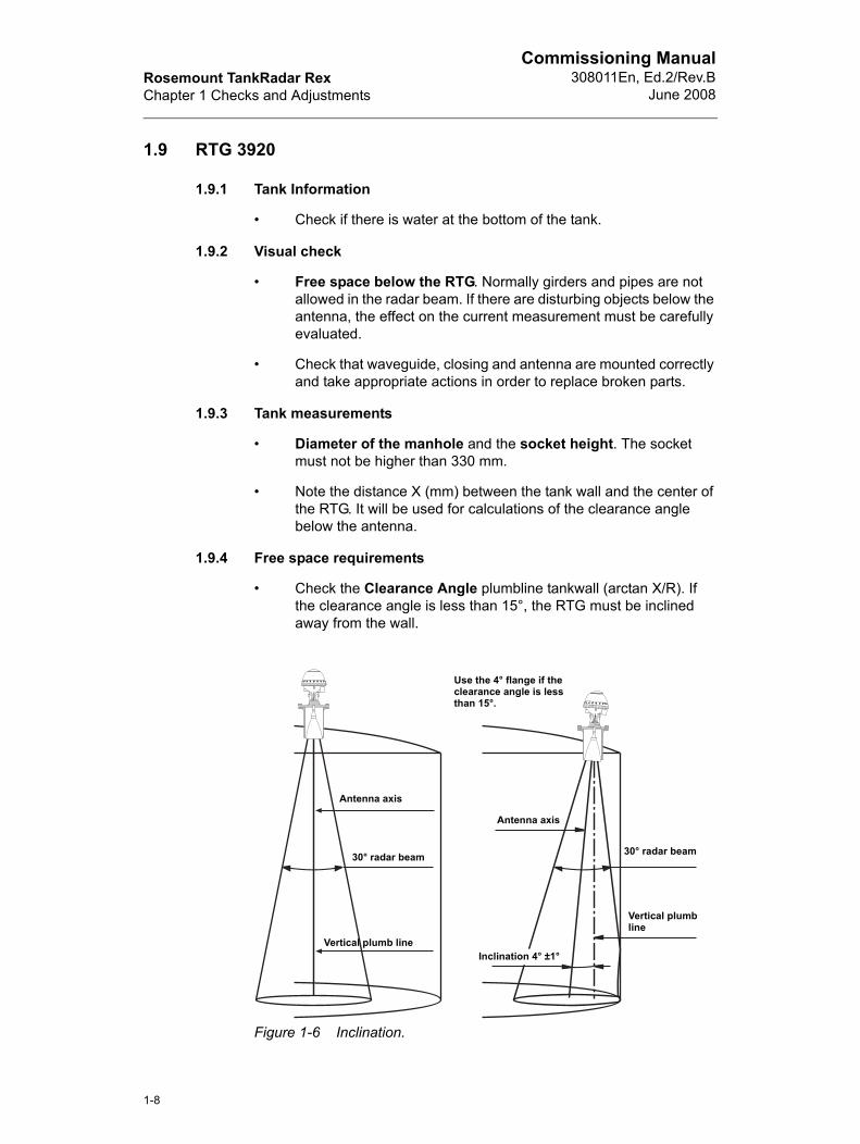
• Check the Clearance Angle plumbline tankwall (arctan X/R). If the clearance angle is less than 15°, the RTG must be inclined away from the wall.
Figure 1-6 Inclination.
Antenna axis
30° radar beam
Vertical plumb lineInclination 4° ±1°
Antenna axis
30° radar beam
Use the 4° flange if the clearance angle is less than 15°.
Vertical plumb line
1-8
Rosemount TankRadar RexChapter 1 Checks and Adjustments
Commissioning Manual308011En, Ed.2/Rev.BJune 2008
le
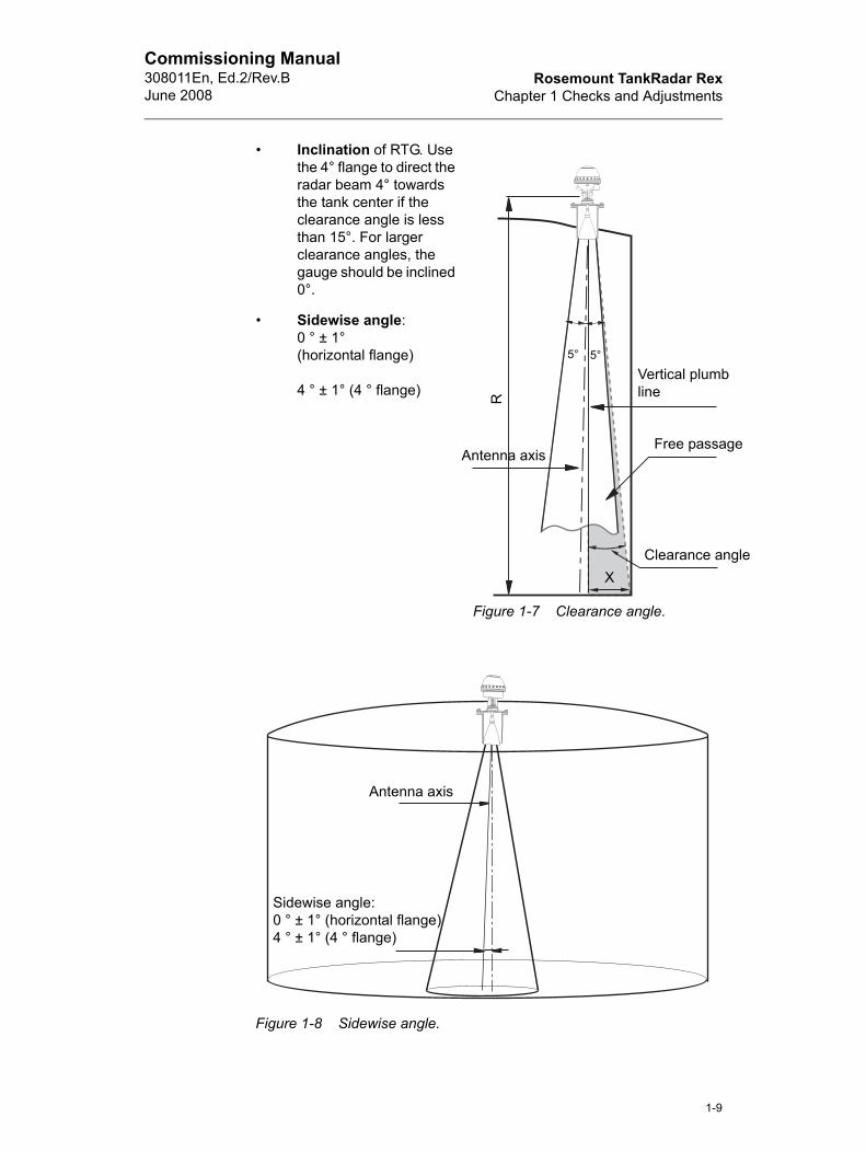
• Inclination of RTG. Use the 4° flange to direct the radar beam 4° towards the tank center if the clearance angle is less than 15°. For larger clearance angles, the gauge should be inclined 0°.
• Sidewise angle:0 ° ± 1°(horizontal flange)
4 ° ± 1° (4 ° flange)
Figure 1-7 Clearance angle.
5°5°
R
Figure 1-8 Sidewise angle.
Antenna axis
Sidewise angle:0 ° ± 1° (horizontal flange)4 ° ± 1° (4 ° flange)
Vertical plumb line
Free passage
Clearance angX
Antenna axis
1-9
Rosemount TankRadar RexChapter 1 Checks and Adjustments
Commissioning Manual308011En, Ed.2/Rev.B
June 2008
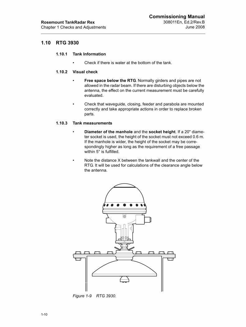
1.10 RTG 3930
1.10.1 Tank Information
• Check if there is water at the bottom of the tank.
1.10.2 Visual check
• Free space below the RTG. Normally girders and pipes are not allowed in the radar beam. If there are disturbing objects below the antenna, the effect on the current measurement must be carefully evaluated.
• Check that waveguide, closing, feeder and parabola are mounted correctly and take appropriate actions in order to replace broken parts.
1.10.3 Tank measurements
• Diameter of the manhole and the socket height. If a 20" diame-ter socket is used, the height of the socket must not exceed 0.6 m. If the manhole is wider, the height of the socket may be corre-spondingly higher as long as the requirement of a free passage within 5° is fulfilled.
• Note the distance X between the tankwall and the center of the RTG. It will be used for calculations of the clearance angle below the antenna.
Figure 1-9 RTG 3930.
1-10
Rosemount TankRadar RexChapter 1 Checks and Adjustments
Commissioning Manual308011En, Ed.2/Rev.BJune 2008
le
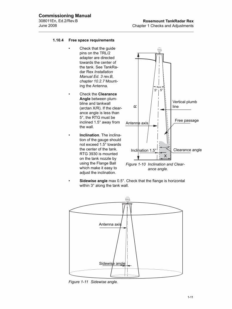
1.10.4 Free space requirements
• Check that the guide pins on the TRL/2 adapter are directed towards the center of the tank. See TankRa-dar Rex Installation Manual Ed. 3 rev.B, chapter 10.2.7 Mount-ing the Antenna.
• Check the Clearance Angle between plum-bline and tankwall (arctan X/R). If the clear-ance angle is less than 5°, the RTG must be inclined 1.5° away from the wall.
• Inclination. The inclina-tion of the gauge should not exceed 1.5° towards the center of the tank. RTG 3930 is mounted on the tank nozzle by using the Flange Ball which make it easy to adjust the inclination.
• Sidewise angle max 0.5°. Check that the flange is horizontal within 3° along the tank wall.
Figure 1-11 Sidewise angle.
Figure 1-10 Inclination and Clear-ance angle.
Antenna axis
5°
R
Antenna axis
Sidewise angle
Vertical plumbline
Free passage
Clearance angX
5°
Inclination 1.5°
1-11
Rosemount TankRadar RexChapter 1 Checks and Adjustments
Commissioning Manual308011En, Ed.2/Rev.B
June 2008
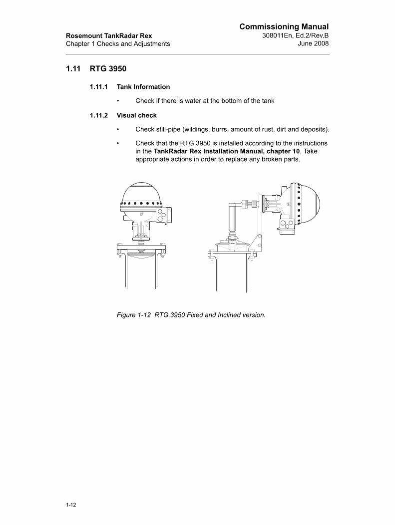
1.11 RTG 3950
1.11.1 Tank Information
• Check if there is water at the bottom of the tank
1.11.2 Visual check
• Check still-pipe (wildings, burrs, amount of rust, dirt and deposits).
• Check that the RTG 3950 is installed according to the instructions in the TankRadar Rex Installation Manual, chapter 10. Take appropriate actions in order to replace any broken parts.
Figure 1-12 RTG 3950 Fixed and Inclined version.
1-12
Rosemount TankRadar RexChapter 1 Checks and Adjustments
Commissioning Manual308011En, Ed.2/Rev.BJune 2008
1.11.3 Still-Pipe Requirements
• Check the number of holes, distance between the holes (unit meter) and the hole diameter (unit mm). It is important that the area of the slots and holes not exceed the specified limits, see Table 1-2.
• Note the pipe inner diameter. It will be used when the RTG is con-figured.
• The still-pipe flange must be horizontal within ±2°.
• The still-pipe must be vertical within 0.5° (0.2 m over 20 m).
Note! The topmost hole/slot in the still-pipe must be placed above maximum product level.
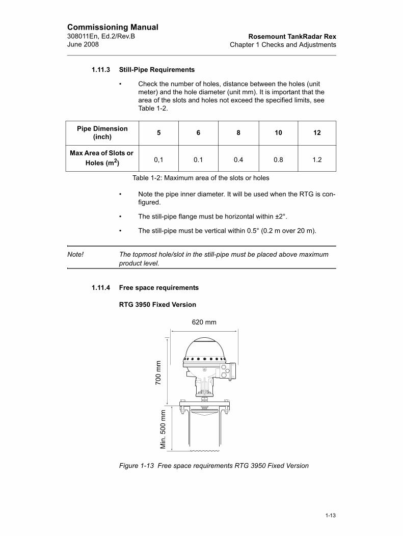
1.11.4 Free space requirements
RTG 3950 Fixed Version
Figure 1-13 Free space requirements RTG 3950 Fixed Version
Pipe Dimension(inch) 5 6 8 10 12
Max Area of Slots or Holes (m2) 0,1 0.1 0.4 0.8 1.2
Table 1-2: Maximum area of the slots or holes
620 mm
700
mm
Min
. 500
mm
1-13
Rosemount TankRadar RexChapter 1 Checks and Adjustments
Commissioning Manual308011En, Ed.2/Rev.B
June 2008
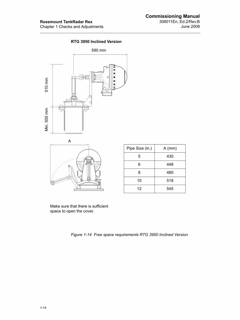
RTG 3950 Inclined Version
Figure 1-14 Free space requirements RTG 3950 Inclined Version
Min
. 500
mm
510
mm
590 mm
A
Make sure that there is sufficient space to open the cover.
Pipe Size (in.) A (mm)
5 430
6 448
8 480
10 518
12 545
1-14
Rosemount TankRadar RexChapter 1 Checks and Adjustments
Commissioning Manual308011En, Ed.2/Rev.BJune 2008
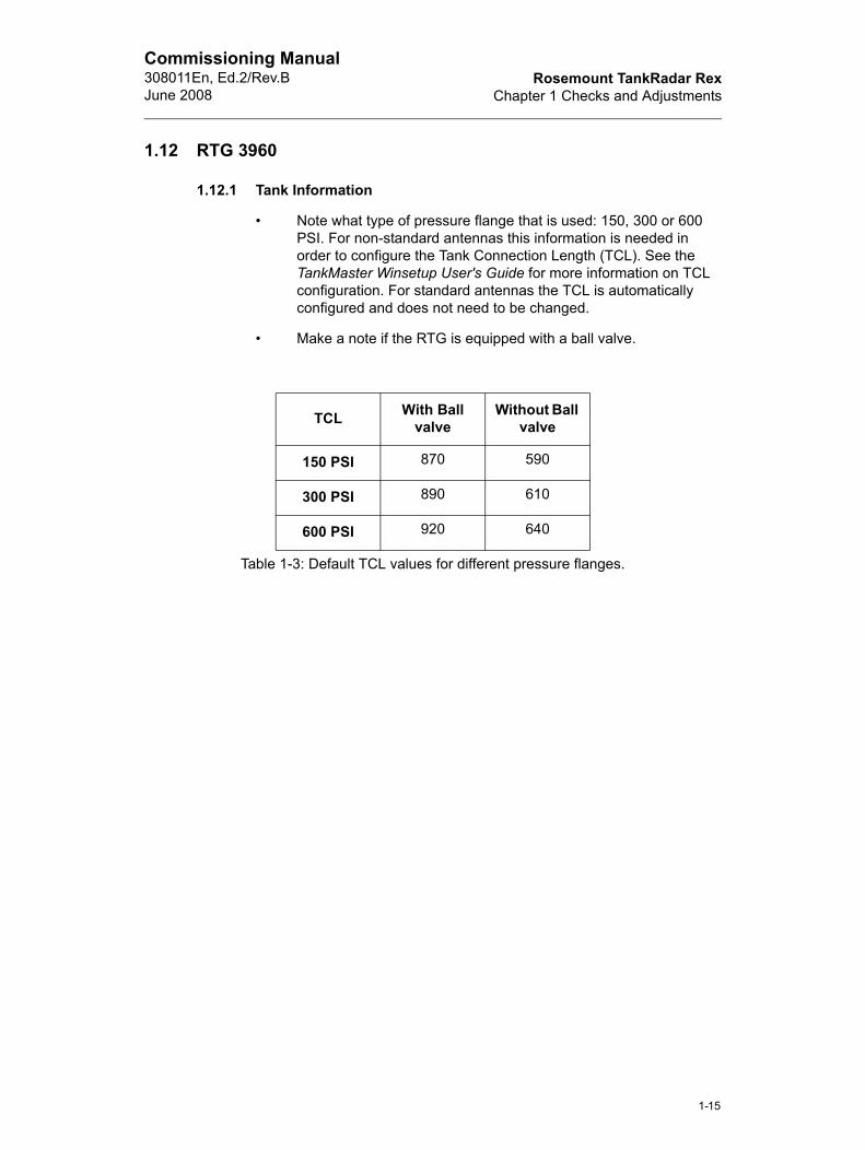
1.12 RTG 3960
1.12.1 Tank Information
• Note what type of pressure flange that is used: 150, 300 or 600 PSI. For non-standard antennas this information is needed in order to configure the Tank Connection Length (TCL). See the TankMaster Winsetup User's Guide for more information on TCL configuration. For standard antennas the TCL is automatically configured and does not need to be changed.
• Make a note if the RTG is equipped with a ball valve.
TCL With Ball valve
Without Ball valve
150 PSI 870 590
300 PSI 890 610
600 PSI 920 640
Table 1-3: Default TCL values for different pressure flanges.
1-15
Rosemount TankRadar RexChapter 1 Checks and Adjustments
Commissioning Manual308011En, Ed.2/Rev.B
June 2008
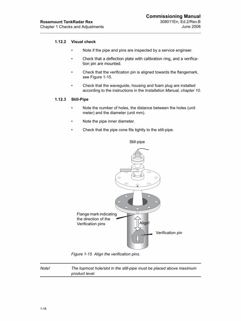
1.12.2 Visual check
• Note if the pipe and pins are inspected by a service engineer.
• Check that a deflection plate with calibration ring, and a verifica-tion pin are mounted.
• Check that the verification pin is aligned towards the flangemark, see Figure 1-15.
• Check that the waveguide, housing and foam plug are installed according to the instructions in the Installation Manual, chapter 10.
1.12.3 Still-Pipe
• Note the number of holes, the distance between the holes (unit meter) and the diameter (unit mm).
• Note the pipe inner diameter.
• Check that the pipe cone fits tightly to the still-pipe.
Figure 1-15 Align the verification pins.
Note! The topmost hole/slot in the still-pipe must be placed above maximum product level.
Align!
Flange mark indicating the direction of the Verification pins
Verification pin
Still-pipe
1-16
Rosemount TankRadar RexChapter 1 Checks and Adjustments
Commissioning Manual308011En, Ed.2/Rev.BJune 2008
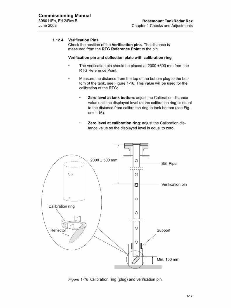
1.12.4 Verification PinsCheck the position of the Verification pins. The distance is measured from the RTG Reference Point to the pin.
Verification pin and deflection plate with calibration ring
• The verification pin should be placed at 2000 ±500 mm from the RTG Reference Point.
• Measure the distance from the top of the bottom plug to the bot-tom of the tank, see Figure 1-16. This value will be used for the calibration of the RTG:
• Zero level at tank bottom: adjust the Calibration distance value until the displayed level (at the calibration ring) is equal to the distance from calibration ring to tank bottom (see Fig-ure 1-16).
• Zero level at calibration ring: adjust the Calibration dis-tance value so the displayed level is equal to zero.
Figure 1-16 Calibration ring (plug) and verification pin.
Calibration ring
Reflector Support
Verification pin
Still-Pipe
Min. 150 mm
2000 ± 500 mm
1-17
Rosemount TankRadar RexChapter 1 Checks and Adjustments
Commissioning Manual308011En, Ed.2/Rev.B
June 2008
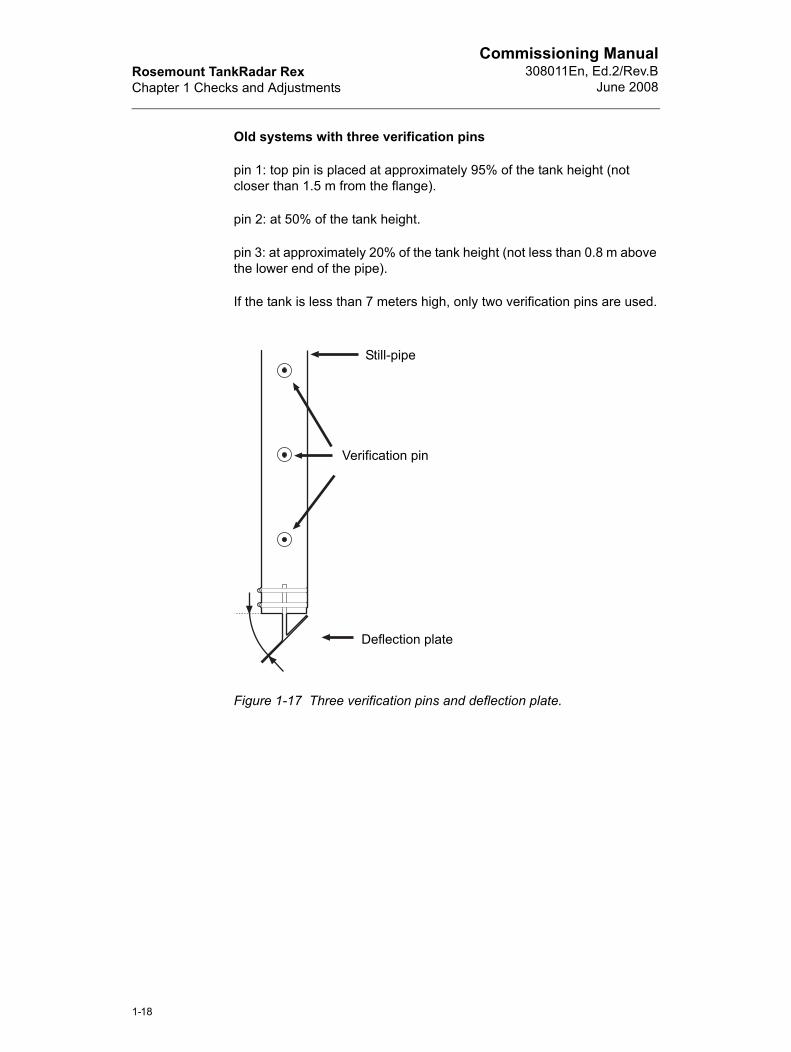
Old systems with three verification pins
pin 1: top pin is placed at approximately 95% of the tank height (not closer than 1.5 m from the flange).
pin 2: at 50% of the tank height.
pin 3: at approximately 20% of the tank height (not less than 0.8 m above the lower end of the pipe).
If the tank is less than 7 meters high, only two verification pins are used.
Figure 1-17 Three verification pins and deflection plate.
Still-pipe
Verification pin
Deflection plate
1-18
Rosemount TankRadar RexChapter 1 Checks and Adjustments
Commissioning Manual308011En, Ed.2/Rev.BJune 2008
1.13 Rex Configuration
1.13.1 Tank Information
Check that the following items are correct in TankMaster:
• Tank name.
• Check that the Unit ID corresponds to the RTG installed at the cur-rent tank.
• RTG address corresponds to the address specified in TankMas-ter.
To view the Unit ID and RTG address:
1 Select the Rex transmitter icon in the WinSetup workspace.
2 Click the right mouse button and choose the Properties option.
3 Select the Communications tab.
1.13.2 Tank Distances and RTG Geometry
Check that the following tank parameters are correct in TankMaster:
• Tank Reference distance, R (Holding register 1000).
• RTG Reference distance, G (Holding register 1002).
• Calibration distance (Holding register 1004).
• Minimum Level distance, C (Holding register 1006)
• Hold off distance (Holding register 1008)
1-19
Rosemount TankRadar RexChapter 1 Checks and Adjustments
Commissioning Manual308011En, Ed.2/Rev.B
June 2008
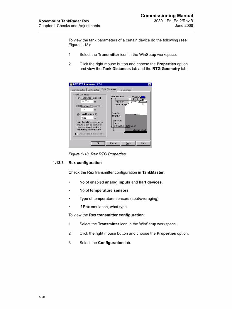
To view the tank parameters of a certain device do the following (see Figure 1-18):
1 Select the Transmitter icon in the WinSetup workspace.
2 Click the right mouse button and choose the Properties option and view the Tank Distances tab and the RTG Geometry tab.
Figure 1-18 Rex RTG Properties.
1.13.3 Rex configuration
Check the Rex transmitter configuration in TankMaster:
• No of enabled analog inputs and hart devices.
• No of temperature sensors.
• Type of temperature sensors (spot/averaging).
• If Rex emulation, what type.
To view the Rex transmitter configuration:
1 Select the Transmitter icon in the WinSetup workspace.
2 Click the right mouse button and choose the Properties option.
3 Select the Configuration tab.
1-20
Rosemount TankRadar RexChapter 1 Checks and Adjustments
Commissioning Manual308011En, Ed.2/Rev.BJune 2008
1.13.4 Input Register parameters
Check the following parameters in TankMaster:
• Device (4000) and Measurement status (4002).
• Level (4006) and Ullage (4008).
• Level rate (4010), Signal strength (4012) and Gain (4016).
• Rex program version (Service > Devices > Properties > Com-munication tab)
Check that Device status (1000), Device error (1002) and Device warning (1004) shows value 0.
To view input register of a certain device do the following:
1 Select the Transmitter icon in the WinSetup workspace.
2 Click the right mouse button and choose View input registers option.
3 Choose All.
4 Type for example 1000 as start value in the Start register field and 10 in the Number of registers.
5 Click the Read button.
See TankMaster WinSetup User’s Guide for a further description on how to view input registers.
1-21
Rosemount TankRadar RexChapter 1 Checks and Adjustments
Commissioning Manual308011En, Ed.2/Rev.B
June 2008
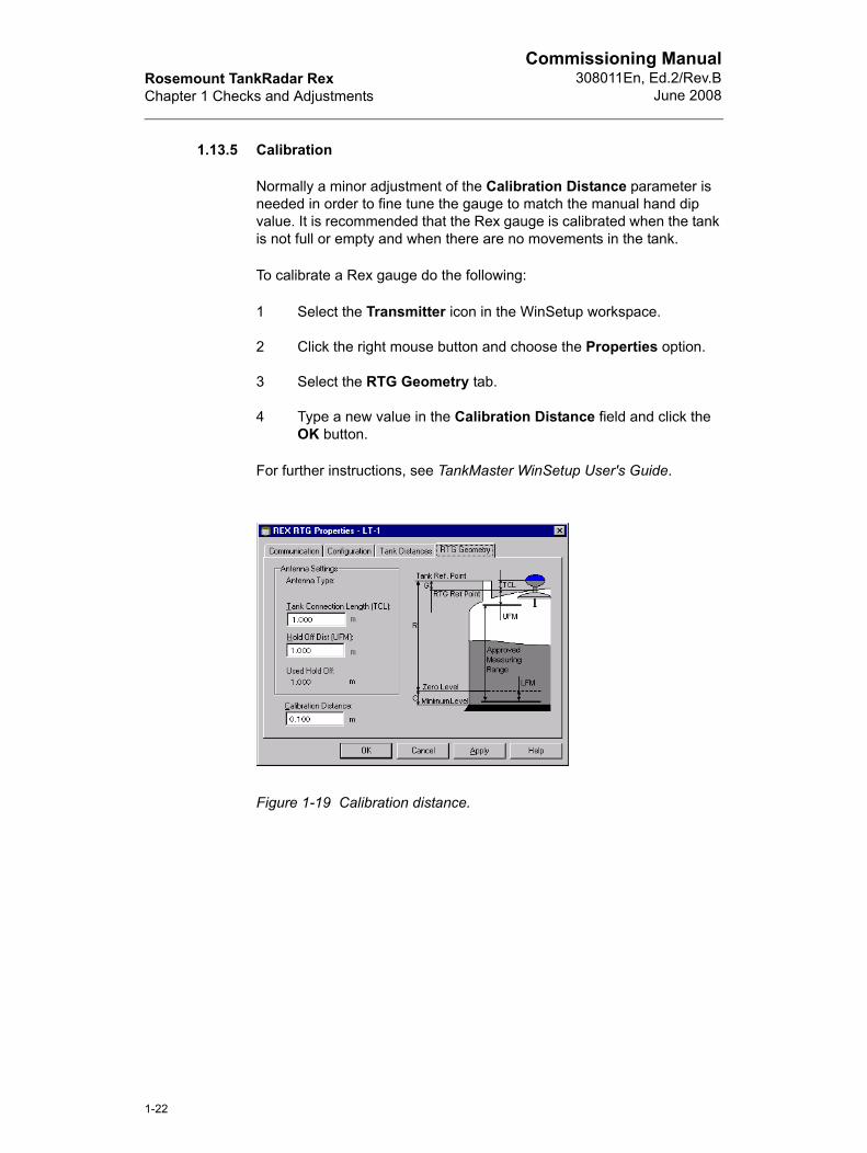
1.13.5 Calibration
Normally a minor adjustment of the Calibration Distance parameter is needed in order to fine tune the gauge to match the manual hand dip value. It is recommended that the Rex gauge is calibrated when the tank is not full or empty and when there are no movements in the tank.
To calibrate a Rex gauge do the following:
1 Select the Transmitter icon in the WinSetup workspace.
2 Click the right mouse button and choose the Properties option.
3 Select the RTG Geometry tab.
4 Type a new value in the Calibration Distance field and click the OK button.
For further instructions, see TankMaster WinSetup User's Guide.
Figure 1-19 Calibration distance.
1-22
Rosemount TankRadar RexChapter 1 Checks and Adjustments
Commissioning Manual308011En, Ed.2/Rev.BJune 2008
1.14 Data Acquisition Unit
1.14.1 Tank Information
• Tank name
• Unit ID
1.14.2 Distance
• Check the distance between the Transmitter Head and the DAU. The distance must not exceed 50 m.
1.14.3 Cable and Junction box
• A shielded cable connected to ground must be used between the RTG and the DAU. The shield shall be grounded in both ends. If an extension cable is used, check that the junction box provides good shielding too.
• If a junction box is used, make sure that it is marked EExi.
1.14.4 Electrical check
DAU
• Measure between 6-7 with X20 connected and disconnected. The corresponding values are ~5.5 VDC and ~12VDC, respectively.
• Make a note if the DAU is externally grounded.
1.14.5 Temperature
• Check that the X1, X2 and X3 jumpers are selected according to the current temperature range. Check that the reference resistor corresponding to the selected temperature range is used. See Installation Manual, chapter 4.3.
• Sensors correctly connected
1-23
Rosemount TankRadar RexChapter 1 Checks and Adjustments
Commissioning Manual308011En, Ed.2/Rev.B
June 2008
1.14.6 Software
• Write protection (on/off)
• If you use the DB loader, note the version. Normally, the DB loader is only used in connection with software upgrading.
• Note which version of the DAU program that is used.
1.15 DAU Configuration
1.15.1 Tank Information
• Tank name
• Check that the Unit ID corresponds to the DAU installed at the cur-rent tank
• Check that the address corresponds to the address specified in TankMaster of the current tank.
1.15.2 Temperature Check
• Check that each temperature sensor outputs a correct value.
• Note the average temperature.
1.15.3 Current inputs
• Note the number of current inputs used, and check the measured values.
1.15.4 Display
• Check that no error codes are displayed.
1-24
Rosemount TankRadar RexChapter 1 Checks and Adjustments
Commissioning Manual308011En, Ed.2/Rev.BJune 2008
1.16 Operator software
1.16.1 TankMaster WinOpi
Note computer related data like:
• Processor
• Clock frequency
• Hard disk space
• RAM
• Com ports used
• Printer type
• Operating system and version
• File system (NTFS, FAT)
• Test the printer report function.
1.16.2 Back-up
Note! TankMaster version and save database registers according to the checklist for:
• FCU
• Rex
• DAU
To save database registers (holding and input registers) do the following:
1 Select the transmitter icon in the WinSetup workspace.
2 Click the right mouse button and choose Save database to file option.
3 Choose Input or Holding register.
4 Choose Predefined (most used registers) or User-defined (lets you specify which registers to save).
5 Click Browse button and specify a location and a name for the file.
6 Click the Save button.
See TankMaster WinSetup User's Guide for instructions on how to save database registers.
1-25

Rosemount TankRadar RexChapter 1 Checks and Adjustments
Commissioning Manual308011En, Ed.2/Rev.B
June 2008
1-26
Rosemount TankRadar RexIndex
Commissioning Manual308011En, Ed.2/Rev.BJune 2008
Index
BBack-up . . . . . . . . . . . . . . . . . . . . . . . . . . . . . . . . . . . . . . . . . . . . . . . . . . . . . . . . . . . . .1-25
CC distance . . . . . . . . . . . . . . . . . . . . . . . . . . . . . . . . . . . . . . . . . . . . . . . . . . . . . . . . . . . .1-7Calibration . . . . . . . . . . . . . . . . . . . . . . . . . . . . . . . . . . . . . . . . . . . . . . . . . . . . . . . . . . .1-22Clearance angle . . . . . . . . . . . . . . . . . . . . . . . . . . . . . . . . . . . . . . . . . . . . . . . . . . 1-9, 1-11
DData Acquisition Unit . . . . . . . . . . . . . . . . . . . . . . . . . . . . . . . . . . . . . . . . . . . . . . . . . .1-23Database registers . . . . . . . . . . . . . . . . . . . . . . . . . . . . . . . . . . . . . . . . . . . . . . . . . . . .1-25DAU Configuration . . . . . . . . . . . . . . . . . . . . . . . . . . . . . . . . . . . . . . . . . . . . . . . . . . . .1-24Deflection plate . . . . . . . . . . . . . . . . . . . . . . . . . . . . . . . . . . . . . . . . . . . . . . . . . . . . . . .1-18Dipping datum point . . . . . . . . . . . . . . . . . . . . . . . . . . . . . . . . . . . . . . . . . . . . . . . . . . . .1-7
FFBM 2180 . . . . . . . . . . . . . . . . . . . . . . . . . . . . . . . . . . . . . . . . . . . . . . . . . . . . . . . . . . . .1-4FCU . . . . . . . . . . . . . . . . . . . . . . . . . . . . . . . . . . . . . . . . . . . . . . . . . . . . . . . . . . . . . . . .1-2Field bus check . . . . . . . . . . . . . . . . . . . . . . . . . . . . . . . . . . . . . . . . . . . . . . . . . . . . 1-3, 1-4Field bus shield . . . . . . . . . . . . . . . . . . . . . . . . . . . . . . . . . . . . . . . . . . . . . . . . . . . . . . . .1-6
GG distance . . . . . . . . . . . . . . . . . . . . . . . . . . . . . . . . . . . . . . . . . . . . . . . . . . . . . . . . . . . .1-7Grounding . . . . . . . . . . . . . . . . . . . . . . . . . . . . . . . . . . . . . . . . . . . . . . . . . . . . . . . . . . . .1-6Group bus check . . . . . . . . . . . . . . . . . . . . . . . . . . . . . . . . . . . . . . . . . . . . . . . . . . . . . . .1-3Guide pins . . . . . . . . . . . . . . . . . . . . . . . . . . . . . . . . . . . . . . . . . . . . . . . . . . . . . . . . . . .1-11
HHand dip nozzle . . . . . . . . . . . . . . . . . . . . . . . . . . . . . . . . . . . . . . . . . . . . . . . . . . . . . . .1-7Hold off distance . . . . . . . . . . . . . . . . . . . . . . . . . . . . . . . . . . . . . . . . . . . . . . . . . . . . . .1-19
IInclination . . . . . . . . . . . . . . . . . . . . . . . . . . . . . . . . . . . . . . . . . . . . . . . . . . . . . . . 1-9, 1-11Input register . . . . . . . . . . . . . . . . . . . . . . . . . . . . . . . . . . . . . . . . . . . . . . . . . . . . . . . . .1-21
RRex Configuration . . . . . . . . . . . . . . . . . . . . . . . . . . . . . . . . . . . . . . . . . . . . . . . . . . . . .1-19RTG . . . . . . . . . . . . . . . . . . . . . . . . . . . . . . . . . . . . . . . . . . . . . . . . . . . . . . . . . . . . . . . .1-6RTG 3920 . . . . . . . . . . . . . . . . . . . . . . . . . . . . . . . . . . . . . . . . . . . . . . . . . . . . . . . . . . . .1-8RTG 3930 . . . . . . . . . . . . . . . . . . . . . . . . . . . . . . . . . . . . . . . . . . . . . . . . . . . . . . . . . . .1-10RTG 3950 . . . . . . . . . . . . . . . . . . . . . . . . . . . . . . . . . . . . . . . . . . . . . . . . . . . . . . . . . . .1-12RTG 3960 . . . . . . . . . . . . . . . . . . . . . . . . . . . . . . . . . . . . . . . . . . . . . . . . . . . . . . . . . . .1-15
Index-1
Rosemount TankRadar RexIndex
Commissioning Manual308011En, Ed.2/Rev.B
June 2008
RTG address . . . . . . . . . . . . . . . . . . . . . . . . . . . . . . . . . . . . . . . . . . . . . . . . . . . . . . . .1-19RTG reference point . . . . . . . . . . . . . . . . . . . . . . . . . . . . . . . . . . . . . . . . . . . . . . . 1-7, 1-17
SSave database registers . . . . . . . . . . . . . . . . . . . . . . . . . . . . . . . . . . . . . . . . . . . . . . . .1-25Sidewise angle . . . . . . . . . . . . . . . . . . . . . . . . . . . . . . . . . . . . . . . . . . . . . . . . . . . 1-9, 1-11
TTank measurements . . . . . . . . . . . . . . . . . . . . . . . . . . . . . . . . . . . . . . . . . . . . . . . . . . . .1-7Tank reference point . . . . . . . . . . . . . . . . . . . . . . . . . . . . . . . . . . . . . . . . . . . . . . . . . . . .1-7TankMaster WinOpi . . . . . . . . . . . . . . . . . . . . . . . . . . . . . . . . . . . . . . . . . . . . . . . . . . .1-25
UUnit ID . . . . . . . . . . . . . . . . . . . . . . . . . . . . . . . . . . . . . . . . . . . . . . . . . . . . . . . . . . 1-6, 1-19
VVerification pin . . . . . . . . . . . . . . . . . . . . . . . . . . . . . . . . . . . . . . . . . . . . . . . . . . 1-17, 1-18
ZZero level . . . . . . . . . . . . . . . . . . . . . . . . . . . . . . . . . . . . . . . . . . . . . . . . . . . . . . . . . . .1-17
Index-2

Commissioning Manual308011En, Ed.2/Rev.BJune 2008
Rosemount Tank Gauging local representative:
Copyright © Rosemount Tank Radar AB. Ref. no: 308011En, Ed.2/Rev.B. June 2008.
Rosemount Tank GaugingBox 130 45SE-402 51 GöteborgSWEDENTel (International): +46 31 337 00 00Fax (International): +46 31 25 30 22E-mail: [email protected]
Emerson Process Management