Embed Size (px)
Citation preview
Manual
TF5100 TwinCAT 3 NC I
TwinCAT 3
1.22018-04-22
Version:Date:

Table of contents
TF5100 TwinCAT 3 NC I 3Version: 1.2
Table of contents1 Introduction................................................................................................................................................ 7
2 User interface in the TwinCAT 3 Engineering environment .................................................................. 82.1 Outline ............................................................................................................................................ 82.2 Interpolation Channel...................................................................................................................... 92.3 Interpreter element ....................................................................................................................... 11
2.3.1 Interpreter online window................................................................................................. 122.3.2 "Interpreter" tab ................................................................................................................ 142.3.3 "M-Functions" tab............................................................................................................. 152.3.4 "R parameters" tab........................................................................................................... 162.3.5 "Zero point" tab ................................................................................................................ 172.3.6 "Tools" tab........................................................................................................................ 182.3.7 "Editor" tab ....................................................................................................................... 192.3.8 "MDI" tab .......................................................................................................................... 20
2.4 Group element .............................................................................................................................. 202.4.1 "General" tab.................................................................................................................... 212.4.2 "DXD" tab ......................................................................................................................... 222.4.3 “Settings” tab.................................................................................................................... 262.4.4 "Online" tab ...................................................................................................................... 272.4.5 "3D-Online" tab ................................................................................................................ 28
3 GST Reference Manual ........................................................................................................................... 293.1 General Notes............................................................................................................................... 293.2 Preprocessor ................................................................................................................................ 293.3 Combining G-Code and ST .......................................................................................................... 313.4 G-Code (DIN 66025)..................................................................................................................... 33
3.4.1 Comments........................................................................................................................ 333.4.2 Codes............................................................................................................................... 343.4.3 Execution Order ............................................................................................................... 463.4.4 Mutual Exclusive G-Codes............................................................................................... 47
3.5 ST - Structured Text (IEC 61131-3).............................................................................................. 473.5.1 Comments........................................................................................................................ 473.5.2 Literals.............................................................................................................................. 483.5.3 Native Data Types............................................................................................................ 513.5.4 Userdefined Types........................................................................................................... 523.5.5 Control Structures ............................................................................................................ 533.5.6 Userdefined Functions ..................................................................................................... 543.5.7 Standard Functions.......................................................................................................... 55
3.6 CNC Functions ............................................................................................................................. 623.6.1 Strings and Messages ..................................................................................................... 623.6.2 Transformations ............................................................................................................... 633.6.3 Movement ........................................................................................................................ 683.6.4 Centerpoint Correction..................................................................................................... 693.6.5 Tools ................................................................................................................................ 693.6.6 Synchronization ............................................................................................................... 713.6.7 Query of Axes .................................................................................................................. 723.6.8 Current Point .................................................................................................................... 733.6.9 Tool Radius Compensation.............................................................................................. 733.6.10 Suppression of G-Code Blocks........................................................................................ 743.6.11 Zero Offset Shift ............................................................................................................... 753.6.12 Units ................................................................................................................................. 763.6.13 Trigonometric (Unit Aware) .............................................................................................. 77
Table of contents
TF5100 TwinCAT 3 NC I4 Version: 1.2
3.6.14 Feed Mode....................................................................................................................... 783.6.15 Feed Interpolation ............................................................................................................ 793.6.16 Streaming of Large G-Code Files .................................................................................... 793.6.17 Vertex Smoothing ............................................................................................................ 793.6.18 Dynamic Override ............................................................................................................ 803.6.19 Center Point Reference of Circles ................................................................................... 80
3.7 Transformations............................................................................................................................ 803.7.1 Modification of the Effective Transformation T and its Effect ........................................... 813.7.2 Components of the Effective Transformation T ............................................................... 823.7.3 Applying Transformations ................................................................................................ 823.7.4 Revoking Transformations ............................................................................................... 823.7.5 Restoration of Stack......................................................................................................... 83
3.8 Error Reporting ............................................................................................................................. 833.8.1 Error Messages................................................................................................................ 843.8.2 Compile-Time Errors and Runtime Errors........................................................................ 843.8.3 Errors in G-Code.............................................................................................................. 853.8.4 Preprocessing .................................................................................................................. 86
3.9 General Command Overview ....................................................................................................... 873.10 Comparative Command Overview................................................................................................ 95
4 Interpreter (DIN 66025/G-Code) ............................................................................................................ 1074.1 Basic Principles of NC Programming.......................................................................................... 107
4.1.1 Structure of an NC Program........................................................................................... 1074.1.2 Block Skipping................................................................................................................ 1084.1.3 Look-Ahead.................................................................................................................... 1084.1.4 Smoothing of Segment Transitions................................................................................ 1104.1.5 Co-ordinate System ....................................................................................................... 1104.1.6 Dimensional Notation..................................................................................................... 1114.1.7 Working Plane and Feed Direction ................................................................................ 1114.1.8 Inch/metric dimensions .................................................................................................. 1134.1.9 Single Block Operation .................................................................................................. 1144.1.10 Arithmetic Parameters.................................................................................................... 115
4.2 Programming Movement Statements ......................................................................................... 1174.2.1 Referencing.................................................................................................................... 1174.2.2 Rapid Traverse............................................................................................................... 1184.2.3 Linear Interpolation ........................................................................................................ 1194.2.4 Circular Interpolation...................................................................................................... 1194.2.5 Helix ............................................................................................................................... 1214.2.6 Dwell Time ..................................................................................................................... 1224.2.7 Accurate Stop................................................................................................................. 1234.2.8 Feed interpolation .......................................................................................................... 1234.2.9 Zero Offset Shifts ........................................................................................................... 1244.2.10 Target Position Monitoring ............................................................................................. 1264.2.11 Contour definitions ......................................................................................................... 1284.2.12 Rotation.......................................................................................................................... 1294.2.13 Mirror.............................................................................................................................. 1324.2.14 Smoothing of segment transitions.................................................................................. 1334.2.15 Circular Smoothing......................................................................................................... 1384.2.16 Automatic Accurate Stop ............................................................................................... 1394.2.17 Delete Distance to Go.................................................................................................... 1404.2.18 Modulo Movements........................................................................................................ 1404.2.19 Auxiliary axes................................................................................................................. 141
4.3 Supplementary Functions ........................................................................................................... 1454.3.1 M-Functions ................................................................................................................... 1454.3.2 H, T and S Parameters .................................................................................................. 149
Table of contents
TF5100 TwinCAT 3 NC I 5Version: 1.2
4.3.3 Decoder stop.................................................................................................................. 1504.3.4 Jumps............................................................................................................................. 1514.3.5 Loops ............................................................................................................................. 1534.3.6 Subroutine techniques ................................................................................................... 1544.3.7 Dynamic Override .......................................................................................................... 1564.3.8 Altering the Motion Dynamics ........................................................................................ 1564.3.9 Change of the Reduction Parameters............................................................................ 1584.3.10 Change of the Minimum Velocity ................................................................................... 1594.3.11 Read Actual Axis Value ................................................................................................. 1604.3.12 Skip virtual movements .................................................................................................. 1614.3.13 Messages from NC program.......................................................................................... 161
4.4 Tool Compensation..................................................................................................................... 1624.4.1 Tool Data........................................................................................................................ 1624.4.2 Selecting and Deselecting the Length Compensation ................................................... 1644.4.3 Cartesian Tool Translation............................................................................................. 1644.4.4 Cutter Radius Compensation......................................................................................... 1674.4.5 Orthogonal Contour Approach/Departure ...................................................................... 1724.4.6 Path Velocity in Arcs ...................................................................................................... 1724.4.7 Bottle Neck Detection .................................................................................................... 173
4.5 Command overview .................................................................................................................... 1754.5.1 General command overview .......................................................................................... 1754.5.2 @-Command Overview.................................................................................................. 178
5 PLC NCI Libraries .................................................................................................................................. 1815.1 PLC Library: Tc2_NCI................................................................................................................. 181
5.1.1 Configuration.................................................................................................................. 1815.1.2 NCI POUs ...................................................................................................................... 1885.1.3 Parts program generator ................................................................................................ 2435.1.4 Blocks for compatibility with existing programs.............................................................. 2505.1.5 Obsolete......................................................................................................................... 274
5.2 PLC Library: Tc2_PlcInterpolation .............................................................................................. 2765.2.1 FB_NciFeedTablePreparation ....................................................................................... 2785.2.2 FB_NciFeedTable .......................................................................................................... 2795.2.3 Types and Enums .......................................................................................................... 280
6 Samples.................................................................................................................................................. 293
7 Appendix ................................................................................................................................................ 2947.1 Display of the parts program....................................................................................................... 2947.2 Display of technology data.......................................................................................................... 2967.3 Displaying the remaining path length.......................................................................................... 3017.4 Parameterisation......................................................................................................................... 301
7.4.1 Path override (interpreter override types) ...................................................................... 3047.5 Cyclical Channel Interface .......................................................................................................... 3067.6 ADS Return Codes ..................................................................................................................... 3087.7 Overview of NC errors ................................................................................................................ 313
7.7.1 General NC Errors ......................................................................................................... 3147.7.2 Channel Errors ............................................................................................................... 3177.7.3 Group Errors .................................................................................................................. 3217.7.4 Axis Errors...................................................................................................................... 3407.7.5 Encoder Errors ............................................................................................................... 3477.7.6 Controller Errors............................................................................................................. 3537.7.7 Drive Errors .................................................................................................................... 3577.7.8 Table Errors ................................................................................................................... 3627.7.9 NC-PLC Errors ............................................................................................................... 366
Table of contents
TF5100 TwinCAT 3 NC I6 Version: 1.2
7.7.10 Kinematic transformation ............................................................................................... 3727.7.11 Bode Return Codes ....................................................................................................... 3727.7.12 Further Error Codes ....................................................................................................... 375
7.8 Specification "Index group" for NC ( ID [0x01...0xFF] ) .............................................................. 3777.8.1 Specification Ring-0-Manager........................................................................................ 3807.8.2 Specification Channels .................................................................................................. 3827.8.3 Specification Groups...................................................................................................... 3917.8.4 Specification Axes.......................................................................................................... 4077.8.5 Specification Encoder .................................................................................................... 4527.8.6 Specification Controller .................................................................................................. 4677.8.7 Specification Drive ......................................................................................................... 4757.8.8 Specification Tables....................................................................................................... 4827.8.9 Appendix ........................................................................................................................ 487
Introduction
TF5100 TwinCAT 3 NC I 7Version: 1.2
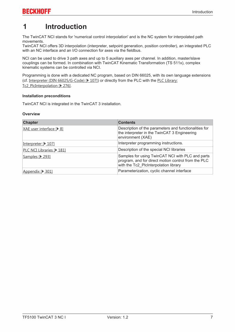
1 IntroductionThe TwinCAT NCI stands for 'numerical control interpolation' and is the NC system for interpolated pathmovements. TwinCAT NCI offers 3D interpolation (interpreter, setpoint generation, position controller), an integrated PLCwith an NC interface and an I/O connection for axes via the fieldbus.
NCI can be used to drive 3 path axes and up to 5 auxiliary axes per channel. In addition, master/slavecouplings can be formed. In combination with TwinCAT Kinematic Transformation (TS 511x), complexkinematic systems can be controlled via NCI.
Programming is done with a dedicated NC program, based on DIN 66025, with its own language extensions(cf. Interpreter (DIN 66025/G-Code) [} 107]) or directly from the PLC with the PLC Library:Tc2_PlcInterpolation [} 276].
Installation preconditions
TwinCAT NCI is integrated in the TwinCAT 3 installation.
Overview
Chapter ContentsXAE user interface [} 8] Description of the parameters and functionalities for
the interpreter in the TwinCAT 3 Engineeringenvironment (XAE)
Interpreter [} 107] Interpreter programming instructions.
PLC NCI Libraries [} 181] Description of the special NCI libraries
Samples [} 293] Samples for using TwinCAT NCI with PLC and partsprogram, and for direct motion control from the PLCwith the Tc2_PlcInterpolation library
Appendix [} 301] Parameterization, cyclic channel interface
User interface in the TwinCAT 3 Engineering environment
TF5100 TwinCAT 3 NC I8 Version: 1.2
2 User interface in the TwinCAT 3 Engineeringenvironment
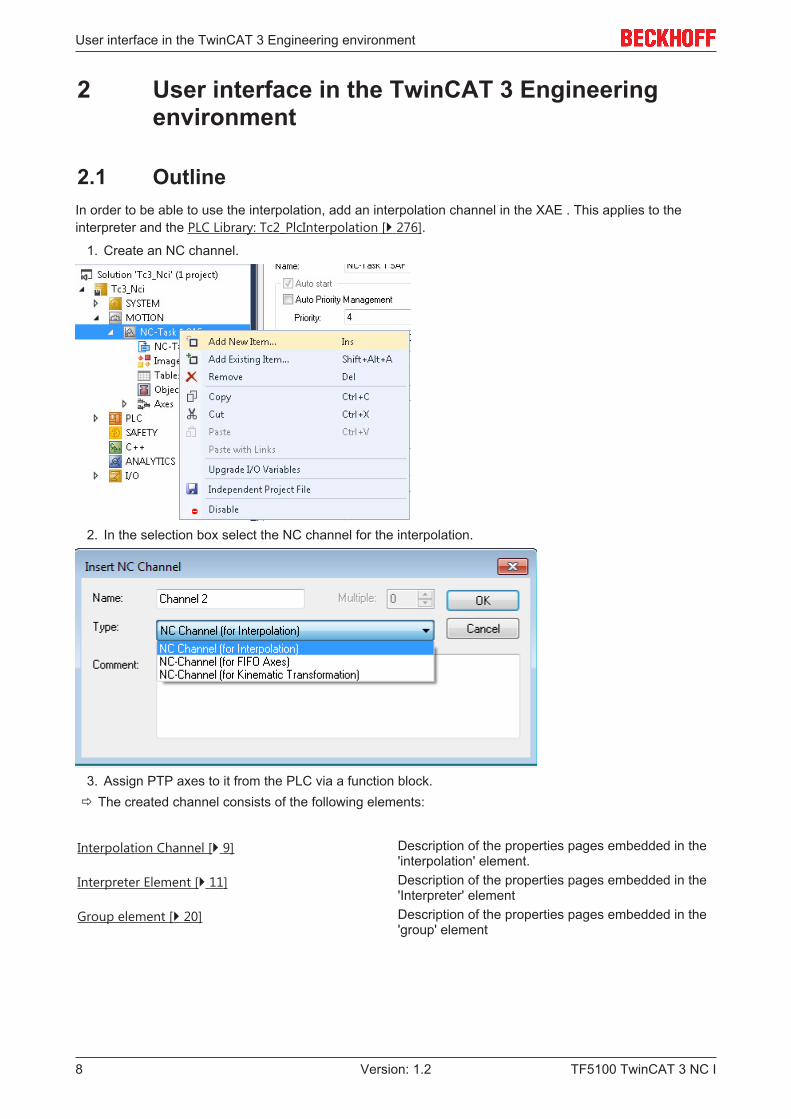
2.1 OutlineIn order to be able to use the interpolation, add an interpolation channel in the XAE . This applies to theinterpreter and the PLC Library: Tc2_PlcInterpolation [} 276].
1. Create an NC channel.
2. In the selection box select the NC channel for the interpolation.
3. Assign PTP axes to it from the PLC via a function block.ð The created channel consists of the following elements:
Interpolation Channel [} 9] Description of the properties pages embedded in the'interpolation' element.
Interpreter Element [} 11] Description of the properties pages embedded in the'Interpreter' element
Group element [} 20] Description of the properties pages embedded in the'group' element
User interface in the TwinCAT 3 Engineering environment
TF5100 TwinCAT 3 NC I 9Version: 1.2
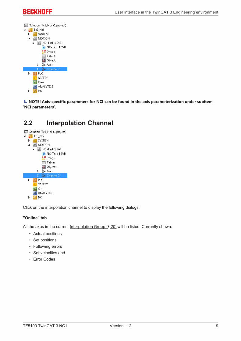
NOTE! Axis-specific parameters for NCI can be found in the axis parameterization under subitem'NCI parameters'.
2.2 Interpolation Channel
Click on the interpolation channel to display the following dialogs:
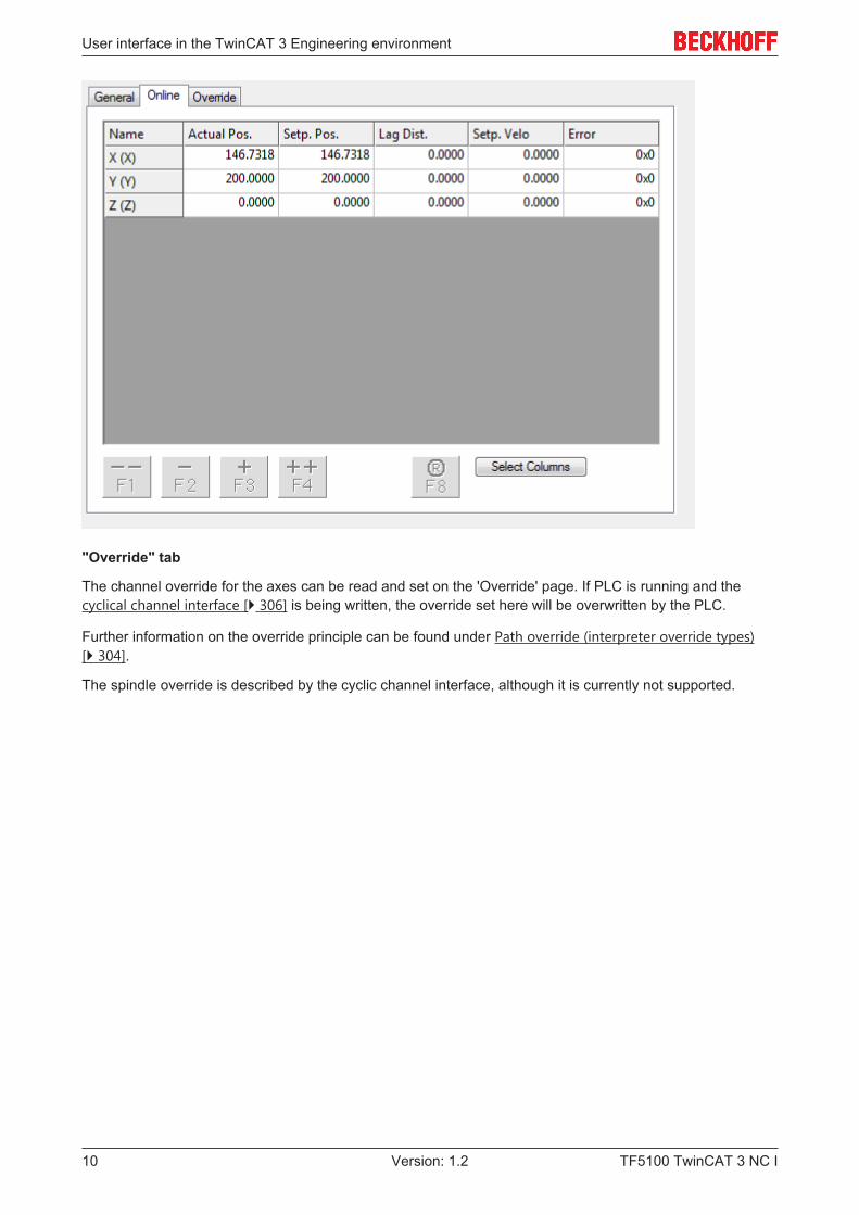
”Online" tab
All the axes in the current Interpolation Group [} 20] will be listed. Currently shown:
• Actual positions• Set positions• Following errors• Set velocities and• Error Codes
User interface in the TwinCAT 3 Engineering environment
TF5100 TwinCAT 3 NC I10 Version: 1.2
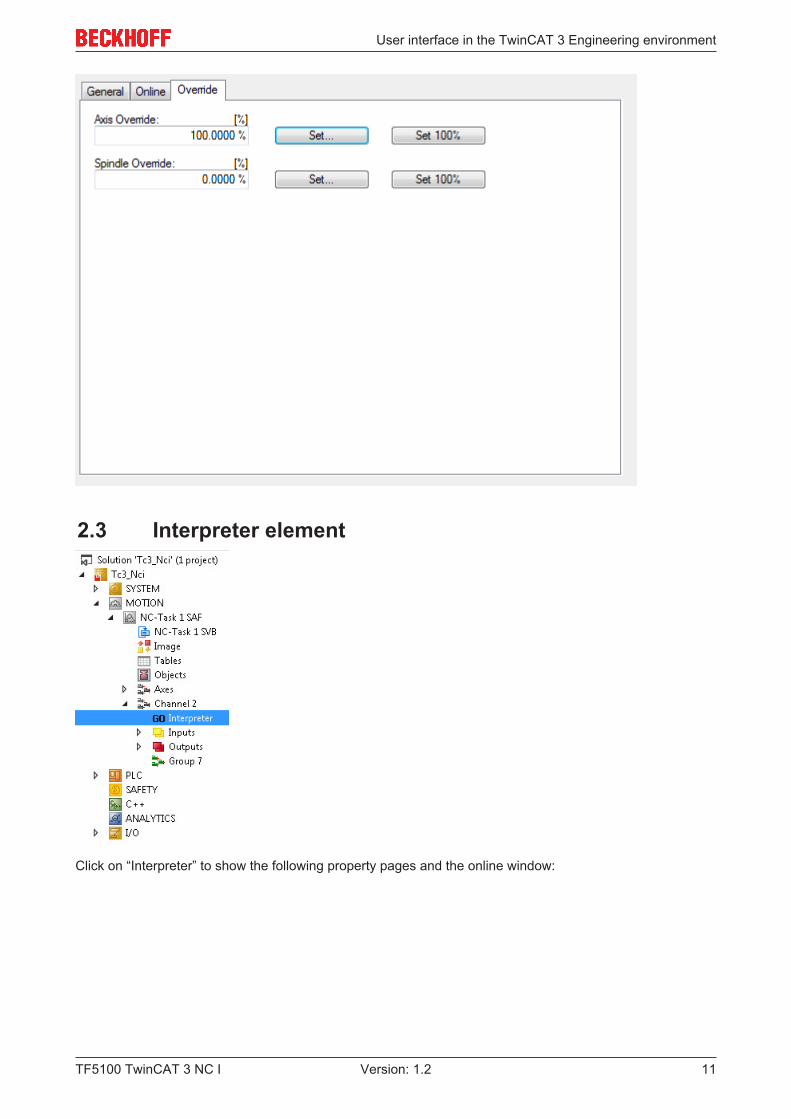
"Override" tab
The channel override for the axes can be read and set on the 'Override' page. If PLC is running and thecyclical channel interface [} 306] is being written, the override set here will be overwritten by the PLC.
Further information on the override principle can be found under Path override (interpreter override types)[} 304].
The spindle override is described by the cyclic channel interface, although it is currently not supported.
User interface in the TwinCAT 3 Engineering environment
TF5100 TwinCAT 3 NC I 11Version: 1.2
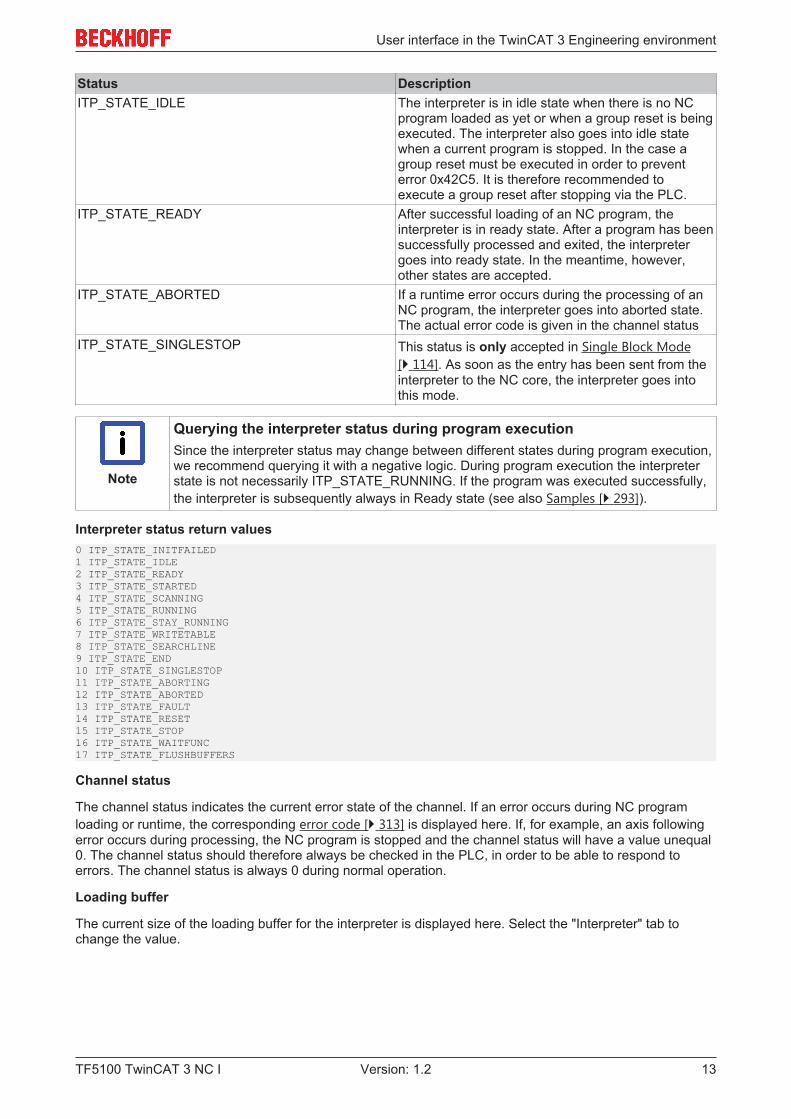
2.3 Interpreter element
Click on “Interpreter” to show the following property pages and the online window:

User interface in the TwinCAT 3 Engineering environment
TF5100 TwinCAT 3 NC I12 Version: 1.2
2.3.1 Interpreter online window
Axes
As on the "Online" properties page in the interpolation channel, this window lists all axes currently included inthe interpolation group. Values for the following parameters are displayed:
• actual positions• set positions• following errors• set velocities and• current error codes
.
Actual Program Line
The Actual Program Line shows the current NC block to be processed in the block execution. The last row inthe window is the current block.
As for nearly all the parameters, the program display can be read off via ADS. This can be used to displaythe current NC blocks in a Visual Basic application, for example (see ADS device documentation - ADSInterface NC [} 308]).
Program name
Displays the name of the currently loaded program. This does not necessarily have to be the programdisplayed in Editor.
Interpreter status
The interpreter status indicates the current status of the interpreter state machine. The complete list is givenbelow. As PLC evaluation does not require all status information, only the most important parameters areexplained.
User interface in the TwinCAT 3 Engineering environment
TF5100 TwinCAT 3 NC I 13Version: 1.2
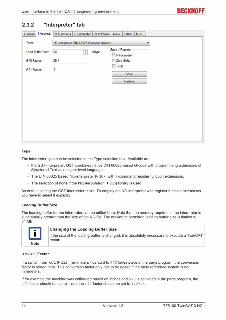
Status DescriptionITP_STATE_IDLE The interpreter is in idle state when there is no NC
program loaded as yet or when a group reset is beingexecuted. The interpreter also goes into idle statewhen a current program is stopped. In the case agroup reset must be executed in order to preventerror 0x42C5. It is therefore recommended toexecute a group reset after stopping via the PLC.
ITP_STATE_READY After successful loading of an NC program, theinterpreter is in ready state. After a program has beensuccessfully processed and exited, the interpretergoes into ready state. In the meantime, however,other states are accepted.
ITP_STATE_ABORTED If a runtime error occurs during the processing of anNC program, the interpreter goes into aborted state.The actual error code is given in the channel status
ITP_STATE_SINGLESTOP This status is only accepted in Single Block Mode[} 114]. As soon as the entry has been sent from theinterpreter to the NC core, the interpreter goes intothis mode.
Note
Querying the interpreter status during program executionSince the interpreter status may change between different states during program execution,we recommend querying it with a negative logic. During program execution the interpreterstate is not necessarily ITP_STATE_RUNNING. If the program was executed successfully,the interpreter is subsequently always in Ready state (see also Samples [} 293]).
Interpreter status return values0 ITP_STATE_INITFAILED1 ITP_STATE_IDLE2 ITP_STATE_READY3 ITP_STATE_STARTED4 ITP_STATE_SCANNING5 ITP_STATE_RUNNING6 ITP_STATE_STAY_RUNNING7 ITP_STATE_WRITETABLE8 ITP_STATE_SEARCHLINE9 ITP_STATE_END10 ITP_STATE_SINGLESTOP11 ITP_STATE_ABORTING12 ITP_STATE_ABORTED13 ITP_STATE_FAULT14 ITP_STATE_RESET15 ITP_STATE_STOP16 ITP_STATE_WAITFUNC17 ITP_STATE_FLUSHBUFFERS
Channel status
The channel status indicates the current error state of the channel. If an error occurs during NC programloading or runtime, the corresponding error code [} 313] is displayed here. If, for example, an axis followingerror occurs during processing, the NC program is stopped and the channel status will have a value unequal0. The channel status should therefore always be checked in the PLC, in order to be able to respond toerrors. The channel status is always 0 during normal operation.
Loading buffer
The current size of the loading buffer for the interpreter is displayed here. Select the "Interpreter" tab tochange the value.
User interface in the TwinCAT 3 Engineering environment
TF5100 TwinCAT 3 NC I14 Version: 1.2
2.3.2 "Interpreter" tab
Type
The interpreter type can be selected in the Type selection box. Available are
• the GST-interpreter. GST combines native DIN 66025 based G-code with programming extensions ofStructured Text as a higher level language.
• The DIN 66025 based NC-interpreter [} 107] with @-command register function extensions.
• The selection of none if the PlcInterpolation [} 276] library is used.
As default setting the GST-interpreter is set. To employ the NC-interpreter with register function extensionsyou have to select it explicitly.
Loading Buffer Size
The loading buffer for the interpreter can be edited here. Note that the memory required in the interpreter issubstantially greater than the size of the NC-file. The maximum permitted loading buffer size is limited to64 MB.
Note
Changing the Loading Buffer SizeIf the size of the loading buffer is changed, it is absolutely necessary to execute a TwinCATrestart.
G70/G71 Factor
If a switch from G71 [} 113] (millimeters - default) to G70 takes place in the parts program, the conversionfactor is stored here. This conversion factor only has to be edited if the base reference system is notmillimeters.
If for example the machine was calibrated based on inches and G70 is activated in the parts program, theG70 factor should be set to 1 and the G71 factor should be set to 1/25.4.
User interface in the TwinCAT 3 Engineering environment
TF5100 TwinCAT 3 NC I 15Version: 1.2
Save/Restore
At runtime the Save function can be used to save a “snapshot” of the current parameters. The checkboxescan be used to specify the parameters to be saved. The Save function generates the file ‘SnapShot.bin’ inthe TwinCAT\CNC directory.
The Restore function loads the file saved with the Save function. This function is solely intended fordebugging purposes.
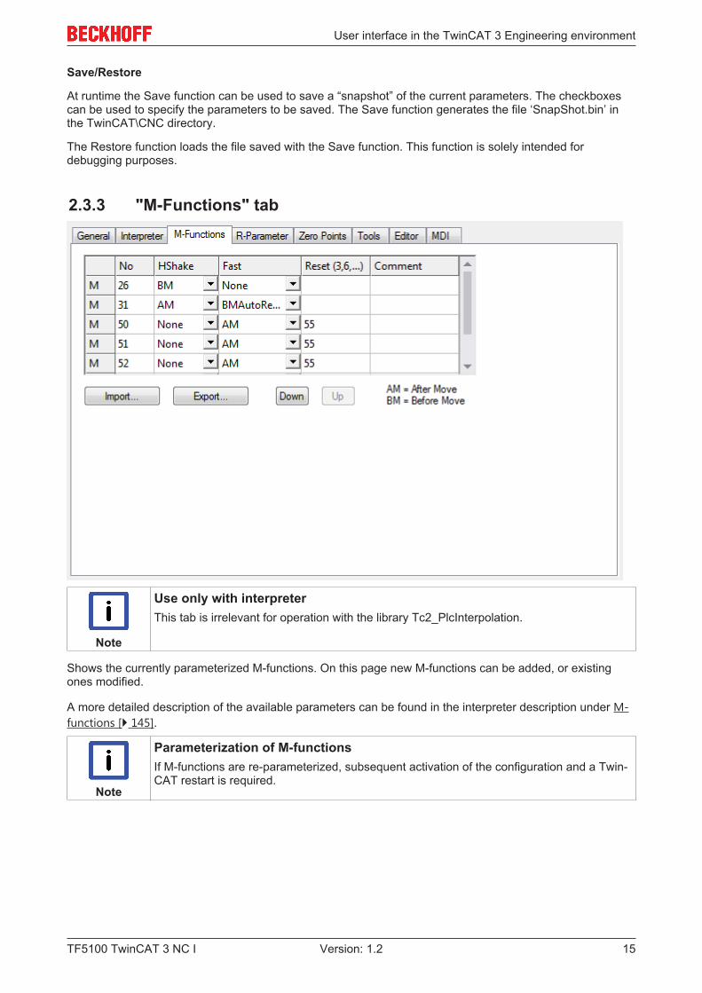
2.3.3 "M-Functions" tab
Note
Use only with interpreterThis tab is irrelevant for operation with the library Tc2_PlcInterpolation.
Shows the currently parameterized M-functions. On this page new M-functions can be added, or existingones modified.
A more detailed description of the available parameters can be found in the interpreter description under M-functions [} 145].
Note
Parameterization of M-functionsIf M-functions are re-parameterized, subsequent activation of the configuration and a Twin-CAT restart is required.
User interface in the TwinCAT 3 Engineering environment
TF5100 TwinCAT 3 NC I16 Version: 1.2
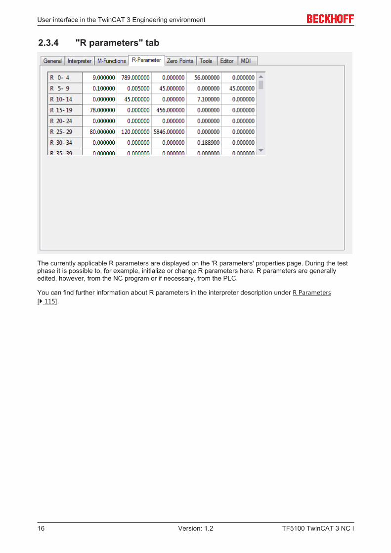
2.3.4 "R parameters" tab
The currently applicable R parameters are displayed on the 'R parameters' properties page. During the testphase it is possible to, for example, initialize or change R parameters here. R parameters are generallyedited, however, from the NC program or if necessary, from the PLC.
You can find further information about R parameters in the interpreter description under R Parameters[} 115].
User interface in the TwinCAT 3 Engineering environment
TF5100 TwinCAT 3 NC I 17Version: 1.2
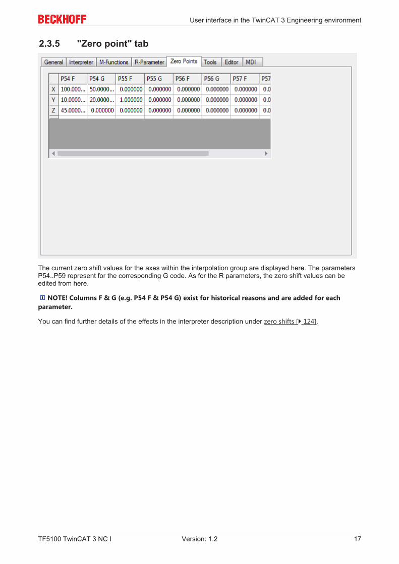
2.3.5 "Zero point" tab
The current zero shift values for the axes within the interpolation group are displayed here. The parametersP54..P59 represent for the corresponding G code. As for the R parameters, the zero shift values can beedited from here.
NOTE! Columns F & G (e.g. P54 F & P54 G) exist for historical reasons and are added for eachparameter.
You can find further details of the effects in the interpreter description under zero shifts [} 124].
User interface in the TwinCAT 3 Engineering environment
TF5100 TwinCAT 3 NC I18 Version: 1.2
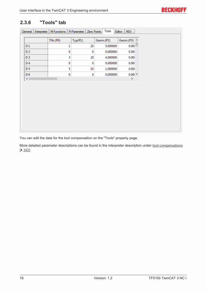
2.3.6 "Tools" tab
You can edit the data for the tool compensation on the "Tools" property page.
More detailed parameter descriptions can be found in the interpreter description under tool compensations[} 162].
User interface in the TwinCAT 3 Engineering environment
TF5100 TwinCAT 3 NC I 19Version: 1.2
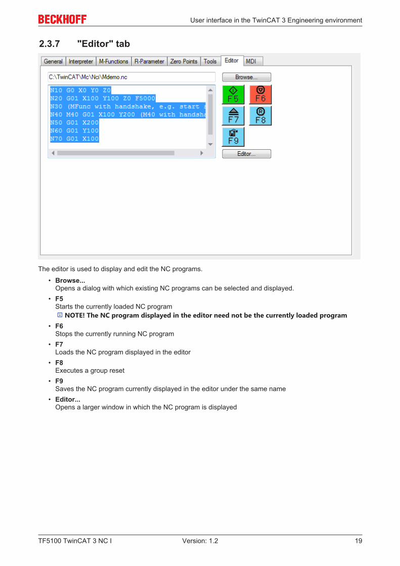
2.3.7 "Editor" tab
The editor is used to display and edit the NC programs.
• Browse...Opens a dialog with which existing NC programs can be selected and displayed.
• F5Starts the currently loaded NC program
NOTE! The NC program displayed in the editor need not be the currently loaded program• F6
Stops the currently running NC program• F7
Loads the NC program displayed in the editor• F8
Executes a group reset• F9
Saves the NC program currently displayed in the editor under the same name• Editor...
Opens a larger window in which the NC program is displayed
User interface in the TwinCAT 3 Engineering environment
TF5100 TwinCAT 3 NC I20 Version: 1.2
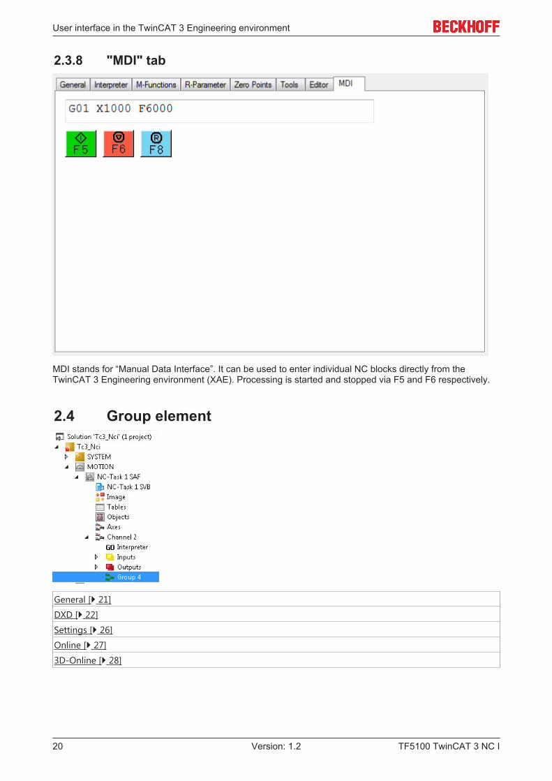
2.3.8 "MDI" tab
MDI stands for “Manual Data Interface”. It can be used to enter individual NC blocks directly from theTwinCAT 3 Engineering environment (XAE). Processing is started and stopped via F5 and F6 respectively.
2.4 Group element
General [} 21]
DXD [} 22]
Settings [} 26]
Online [} 27]
3D-Online [} 28]
User interface in the TwinCAT 3 Engineering environment
TF5100 TwinCAT 3 NC I 21Version: 1.2
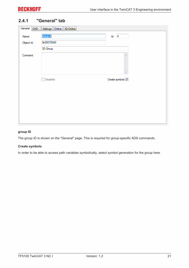
2.4.1 "General" tab
group ID
The group ID is shown on the "General" page. This is required for group-specific ADS commands.
Create symbols
In order to be able to access path variables symbolically, select symbol generation for the group here.
User interface in the TwinCAT 3 Engineering environment
TF5100 TwinCAT 3 NC I22 Version: 1.2
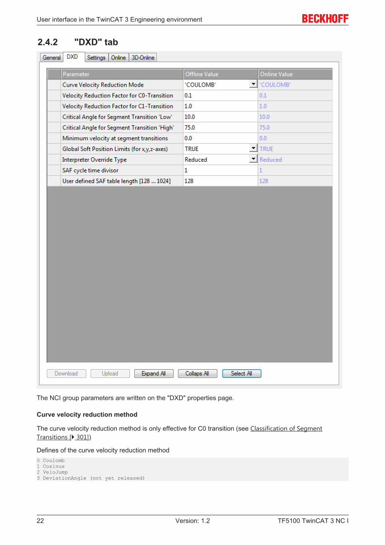
2.4.2 "DXD" tab
The NCI group parameters are written on the "DXD" properties page.
Curve velocity reduction method
The curve velocity reduction method is only effective for C0 transition (see Classification of SegmentTransitions [} 301])
Defines of the curve velocity reduction method0 Coulomb1 Cosinus2 VeloJump3 DeviationAngle (not yet released)
User interface in the TwinCAT 3 Engineering environment
TF5100 TwinCAT 3 NC I 23Version: 1.2
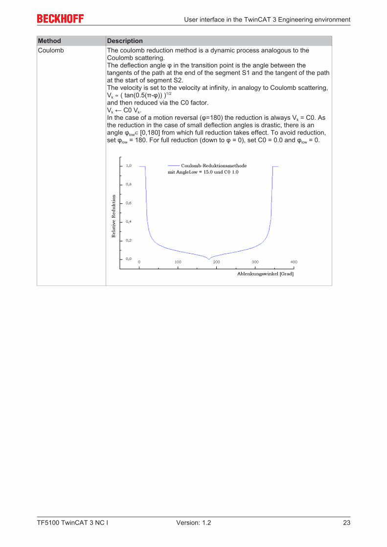
Method DescriptionCoulomb The coulomb reduction method is a dynamic process analogous to the
Coulomb scattering.The deflection angle φ in the transition point is the angle between thetangents of the path at the end of the segment S1 and the tangent of the pathat the start of segment S2.The velocity is set to the velocity at infinity, in analogy to Coulomb scattering,Vk ∝ ( tan(0.5(π-φ)) )1/2
and then reduced via the C0 factor.Vk ← C0 Vk.In the case of a motion reversal (φ=180) the reduction is always Vk = C0. Asthe reduction in the case of small deflection angles is drastic, there is anangle φlow∈ [0,180] from which full reduction takes effect. To avoid reduction,set φlow = 180. For full reduction (down to φ = 0), set C0 = 0.0 and φlow = 0.
User interface in the TwinCAT 3 Engineering environment
TF5100 TwinCAT 3 NC I24 Version: 1.2
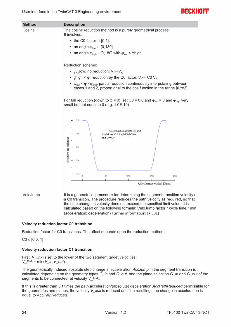
Method DescriptionCosine The cosine reduction method is a purely geometrical process.
It involves:• the C0 factor ∈ [0,1],• an angle φlow ∈ [0,180],• an angle φhigh ∈ [0,180] with φlow < φhigh
Reduction scheme:• φ < φlow: no reduction: Vk←Vk,
• φhigh < φ: reduction by the C0 factor: Vk← C0 Vk
• φlow < φ <φhigh: partial reduction continuously interpolating betweencases 1 and 2, proportional to the cos function in the range [0,π/2].
For full reduction (down to φ = 0), set C0 = 0.0 and φlow = 0 and φhigh verysmall but not equal to 0 (e.g. 1.0E-10)
VeloJump It is a geometrical procedure for determining the segment transition velocity ata C0 transition. The procedure reduces the path velocity as required, so thatthe step change in velocity does not exceed the specified limit value. It iscalculated based on the following formula: VeloJump factor * cycle time * min(acceleration; deceleration) Further information: [} 301]
Velocity reduction factor C0 transition
Reduction factor for C0 transitions. The effect depends upon the reduction method.
C0 ∈ [0.0, 1]
Velocity reduction factor C1 transition
First, V_link is set to the lower of the two segment target velocities: V_link = min(V_in,V_out).
The geometrically induced absolute step change in acceleration AccJump in the segment transition iscalculated depending on the geometry types G_in and G_out, and the plane selection G_in and G_out of thesegments to be connected, at velocity V_link.
If this is greater than C1 times the path acceleration/(absolute) deceleration AccPathReduced permissible forthe geometries and planes, the velocity V_link is reduced until the resulting step change in acceleration isequal to AccPathReduced.
User interface in the TwinCAT 3 Engineering environment
TF5100 TwinCAT 3 NC I 25Version: 1.2
If this value is less than V_min, then V_min takes priority.
NOTE! When changing the dynamic parameters, the permissible path acceleration for thegeometries and planes and thereby the reaction of the reduction changes automatically.
Reduction factor for C1 transitions: C1 ≥ 0.0
Critical angle, segment transition 'low'
Parameters for φlow (see curve velocity reduction method [} 22]).
Critical angle, segment transition 'high'
Parameters for φhigh (see curve velocity reduction method [} 22]).
Minimum velocity at segment transitions
Each NCI group has a minimum path velocity V_min ≥ 0.0. The actual velocity should always exceed thisvalue. User-specified exceptions are: programmed stop at segment transition, path end and overriderequests which lead to a velocity below the minimum value. A systemic exception is a motion reversal.
With the reduction method DEVIATIONANGLE the deflection angle is φ ≥ φ_h, in which case the minimumvelocity is ignored. V_min must be less than the set value for the path velocity (F word) of each segment.
The minimum velocity can be set to a new value V_min ≥ 0.0 in the NC program at any time. The unit is mm/sec.
Global soft position limits (for x,y,z-axes)
Parameters for enabling the software end positions of the path (see: Parameterization [} 304]).
Interpreter override type
Parameter for selecting the path override type (see Path override (interpreter override types) [} 304]).
SAF cycle time divisor
The cycle time reduction ensures that the set value in the SAF is not calculated with the SAF cycle time, butwith a time that is divided by the value specified here. For highly dynamic motions it may make sense to setthe parameter to a value greater than 1, in order to minimize discretization inaccuracies. Increasing the SAFcycle time divisor results in the set value generator being called more frequently internally.
User-defined SAF table length
Parameter that defines the size of the SAF table and therefore the maximum number of cached SAF entries(look-ahead). If an NC program involves sequential movement of many very short segments, increasing thisvalue can help to avoid an unintentional velocity reduction at the segment transitions.
User interface in the TwinCAT 3 Engineering environment
TF5100 TwinCAT 3 NC I26 Version: 1.2
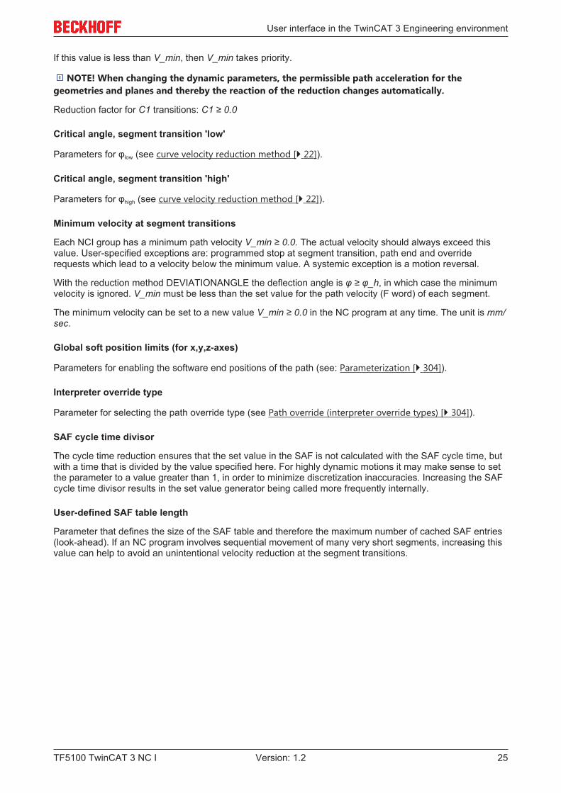
2.4.3 “Settings” tab
Under the "Settings" tab you can set the cycle time for the interpolation. The cycle time set here is a multipleof the cycle time of the SAF task.
Note
Using the cycle time in the "Settings" tabThe cycle time setting can be used if you have to select a cycle time for the interpolationthat differs from the SAF task. Generally, the cycle time of the SAF task should be adjustedto set the cycle time.
User interface in the TwinCAT 3 Engineering environment
TF5100 TwinCAT 3 NC I 27Version: 1.2
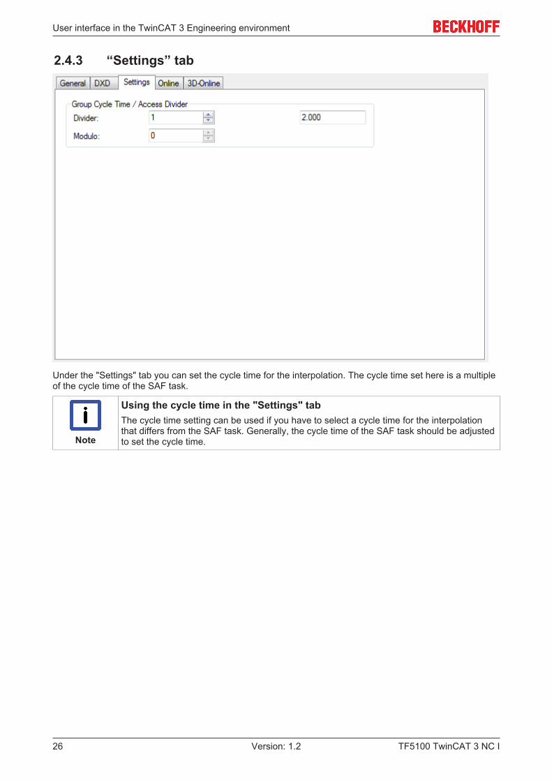
2.4.4 "Online" tab
Error code
The current error code for the channel is displayed here. The value is the same as the value displayed in theonline window of the interpreter under 'channel status [} 11]'
SVB status
SVB status displays the current block preparation status (SVB = Satzvorbereitung). Possible SVB states are:ERRORIDLEREADYSTARTDRIVEOUTCALIBRATEMFUNCSYNCRECDELAYMFUNCWAITSPINDLEWAIT
PLC evaluation of the SVB status is normally not necessary.
SAF status
SAF status displays the current block execution status (SAF = Satzausführung). Possible SAF states are:ERRORIDLECONTROLRUNRUN_DRIVEOUTWAIT
PLC evaluation of the SAF status is normally not necessary.
User interface in the TwinCAT 3 Engineering environment
TF5100 TwinCAT 3 NC I28 Version: 1.2
SVB entries
Number of current SVB entries.
SAF entries
Number of current SAF entries.
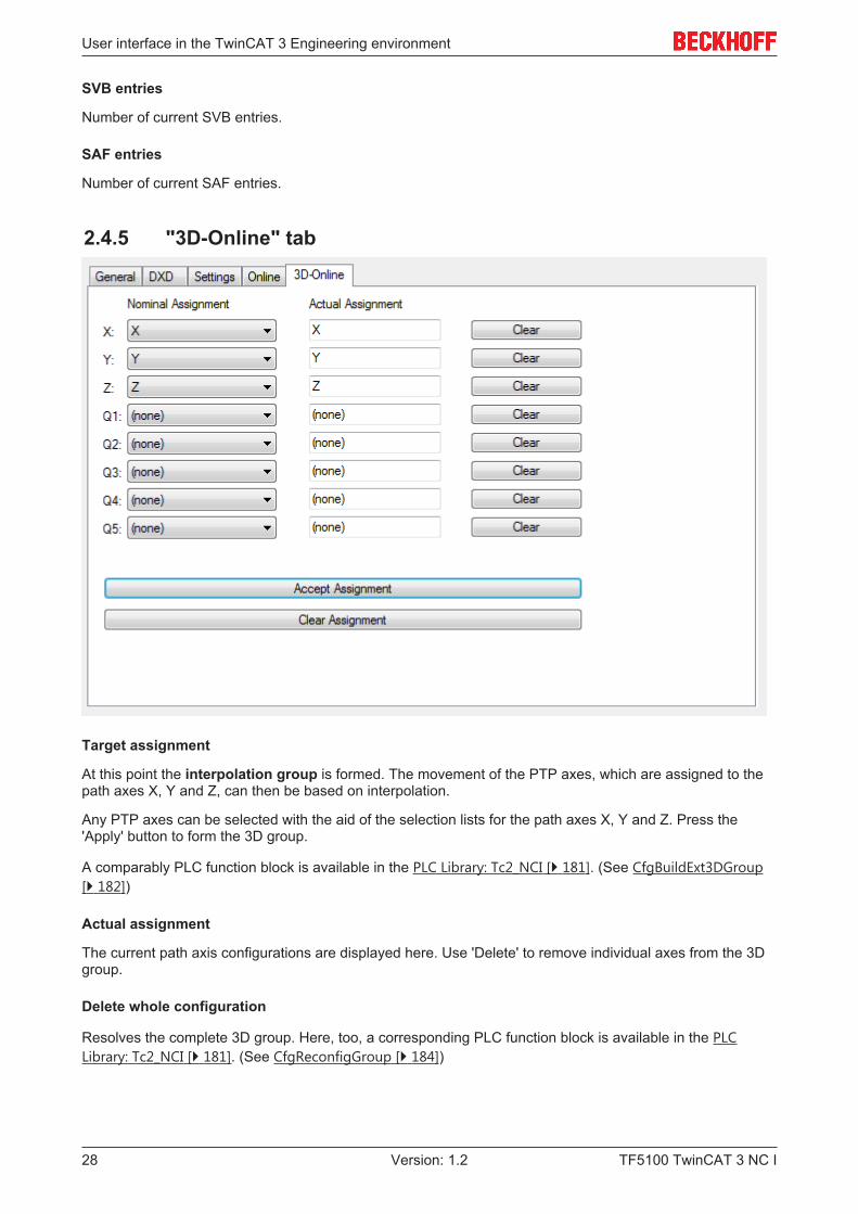
2.4.5 "3D-Online" tab
Target assignment
At this point the interpolation group is formed. The movement of the PTP axes, which are assigned to thepath axes X, Y and Z, can then be based on interpolation.
Any PTP axes can be selected with the aid of the selection lists for the path axes X, Y and Z. Press the'Apply' button to form the 3D group.
A comparably PLC function block is available in the PLC Library: Tc2_NCI [} 181]. (See CfgBuildExt3DGroup[} 182])
Actual assignment
The current path axis configurations are displayed here. Use 'Delete' to remove individual axes from the 3Dgroup.
Delete whole configuration
Resolves the complete 3D group. Here, too, a corresponding PLC function block is available in the PLCLibrary: Tc2_NCI [} 181]. (See CfgReconfigGroup [} 184])
GST Reference Manual
TF5100 TwinCAT 3 NC I 29Version: 1.2
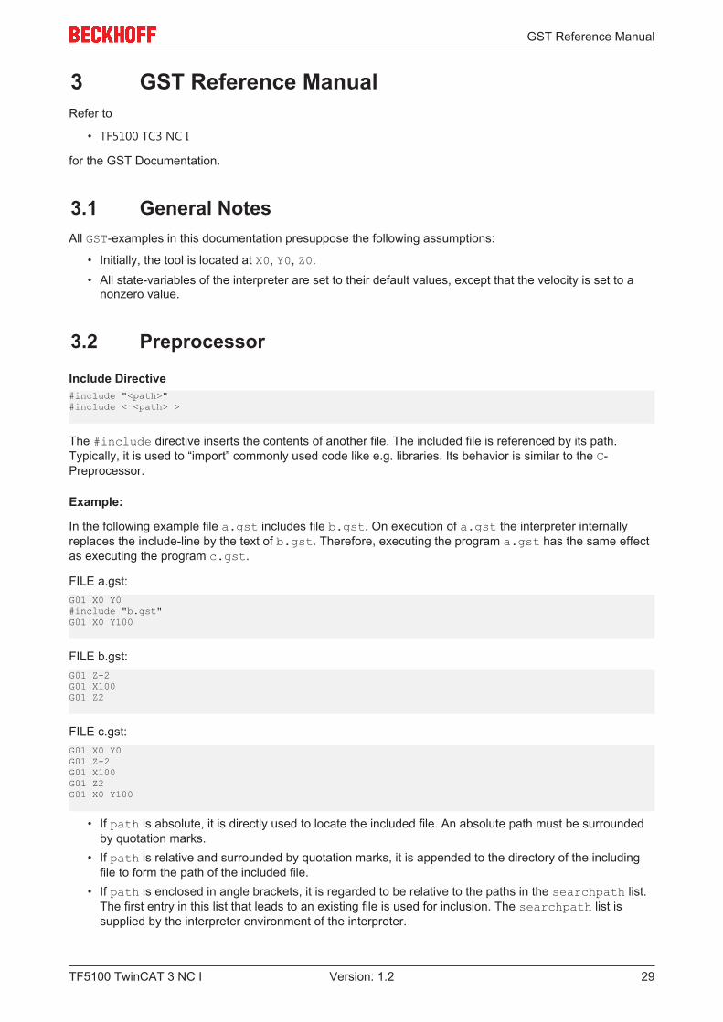
3 GST Reference ManualRefer to
• TF5100 TC3 NC I
for the GST Documentation.
3.1 General NotesAll GST-examples in this documentation presuppose the following assumptions:
• Initially, the tool is located at X0, Y0, Z0.• All state-variables of the interpreter are set to their default values, except that the velocity is set to a
nonzero value.
3.2 Preprocessor
Include Directive#include "<path>"#include < <path> >
The #include directive inserts the contents of another file. The included file is referenced by its path.Typically, it is used to “import” commonly used code like e.g. libraries. Its behavior is similar to the C-Preprocessor.
Example:
In the following example file a.gst includes file b.gst. On execution of a.gst the interpreter internallyreplaces the include-line by the text of b.gst. Therefore, executing the program a.gst has the same effectas executing the program c.gst.
FILE a.gst:G01 X0 Y0#include "b.gst"G01 X0 Y100
FILE b.gst:G01 Z-2G01 X100G01 Z2
FILE c.gst:G01 X0 Y0G01 Z-2G01 X100G01 Z2G01 X0 Y100
• If path is absolute, it is directly used to locate the included file. An absolute path must be surroundedby quotation marks.
• If path is relative and surrounded by quotation marks, it is appended to the directory of the includingfile to form the path of the included file.
• If path is enclosed in angle brackets, it is regarded to be relative to the paths in the searchpath list.The first entry in this list that leads to an existing file is used for inclusion. The searchpath list issupplied by the interpreter environment of the interpreter.
GST Reference Manual
TF5100 TwinCAT 3 NC I30 Version: 1.2
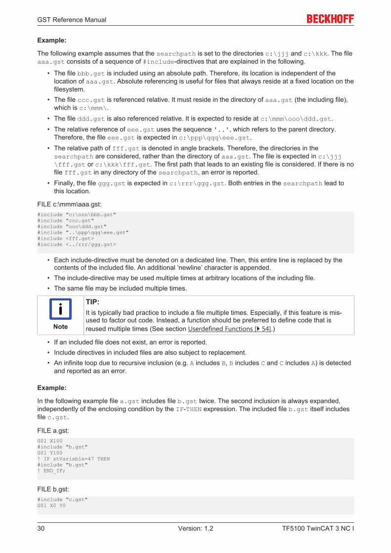
Example:
The following example assumes that the searchpath is set to the directories c:\jjj and c:\kkk. The fileaaa.gst consists of a sequence of #include-directives that are explained in the following.
• The file bbb.gst is included using an absolute path. Therefore, its location is independent of thelocation of aaa.gst. Absolute referencing is useful for files that always reside at a fixed location on thefilesystem.
• The file ccc.gst is referenced relative. It must reside in the directory of aaa.gst (the including file),which is c:\mmm\.
• The file ddd.gst is also referenced relative. It is expected to reside at c:\mmm\ooo\ddd.gst.• The relative reference of eee.gst uses the sequence '..', which refers to the parent directory.
Therefore, the file eee.gst is expected in c:\ppp\qqq\eee.gst.• The relative path of fff.gst is denoted in angle brackets. Therefore, the directories in thesearchpath are considered, rather than the directory of aaa.gst. The file is expected in c:\jjj\fff.gst or c:\kkk\fff.gst. The first path that leads to an existing file is considered. If there is nofile fff.gst in any directory of the searchpath, an error is reported.
• Finally, the file ggg.gst is expected in c:\rrr\ggg.gst. Both entries in the searchpath lead tothis location.
FILE c:\mmm\aaa.gst:#include "c:\nnn\bbb.gst"#include "ccc.gst"#include "ooo\ddd.gst"#include "..\ppp\qqq\eee.gst"#include <fff.gst>#include <../rrr/ggg.gst>
• Each include-directive must be denoted on a dedicated line. Then, this entire line is replaced by thecontents of the included file. An additional ‘newline’ character is appended.
• The include-directive may be used multiple times at arbitrary locations of the including file.• The same file may be included multiple times.
Note
TIP:It is typically bad practice to include a file multiple times. Especially, if this feature is mis-used to factor out code. Instead, a function should be preferred to define code that isreused multiple times (See section Userdefined Functions [} 54].)
• If an included file does not exist, an error is reported.• Include directives in included files are also subject to replacement.• An infinite loop due to recursive inclusion (e.g. A includes B, B includes C and C includes A) is detected
and reported as an error.
Example:
In the following example file a.gst includes file b.gst twice. The second inclusion is always expanded,independently of the enclosing condition by the IF-THEN expression. The included file b.gst itself includesfile c.gst.
FILE a.gst:G01 X100#include "b.gst"G01 Y100! IF stVariable=47 THEN#include "b.gst"! END_IF;
FILE b.gst:#include "c.gst"G01 X0 Y0
GST Reference Manual
TF5100 TwinCAT 3 NC I 31Version: 1.2
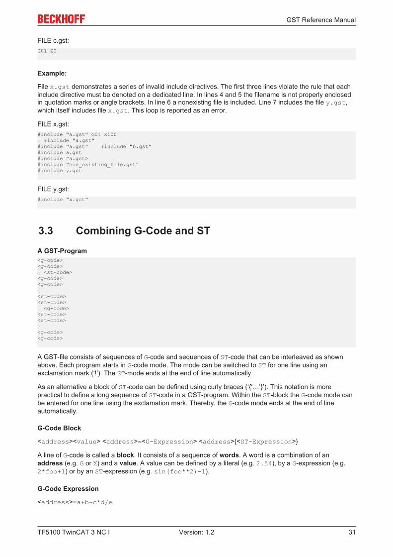
FILE c.gst:G01 Z0
Example:
File x.gst demonstrates a series of invalid include directives. The first three lines violate the rule that eachinclude directive must be denoted on a dedicated line. In lines 4 and 5 the filename is not properly enclosedin quotation marks or angle brackets. In line 6 a nonexisting file is included. Line 7 includes the file y.gst,which itself includes file x.gst. This loop is reported as an error.
FILE x.gst:#include "a.gst" G01 X100! #include "a.gst"#include "a.gst" #include "b.gst"#include a.gst#include "a.gst>#include "non_existing_file.gst"#include y.gst
FILE y.gst:#include "x.gst"
3.3 Combining G-Code and ST
A GST-Program<g-code><g-code>! <st-code><g-code><g-code>{<st-code><st-code>! <g-code><st-code><st-code>}<g-code><g-code>
A GST-file consists of sequences of G-code and sequences of ST-code that can be interleaved as shownabove. Each program starts in G-code mode. The mode can be switched to ST for one line using anexclamation mark (‘!’). The ST-mode ends at the end of line automatically.
As an alternative a block of ST-code can be defined using curly braces (‘{‘…’}’). This notation is morepractical to define a long sequence of ST-code in a GST-program. Within the ST-block the G-code mode canbe entered for one line using the exclamation mark. Thereby, the G-code mode ends at the end of lineautomatically.
G-Code Block
<address><value> <address>=<G-Expression> <address>{<ST-Expression>}
A line of G-code is called a block. It consists of a sequence of words. A word is a combination of anaddress (e.g. G or X) and a value. A value can be defined by a literal (e.g. 2.54), by a G-expression (e.g.2*foo+1) or by an ST-expression (e.g. sin(foo**2)-1).
G-Code Expression
<address>=a+b-c*d/e
GST Reference Manual
TF5100 TwinCAT 3 NC I32 Version: 1.2
The result of the expression is used as the value of the word. The four basic arithmetic operations (‘+’, ‘-’,‘*’, ‘/’) can be used in a G-expression. They are evaluated as expected, i.e. all operations are left-associativeand ‘*’, ‘/’ have a higher precedence than ‘+’, ‘-’. Variables that have been declared in ST can also be usedin a G-expression (with respect to their scope).
All computations are performed using type LReal (64-bit floating point according to IEEE 754). The value ofan ST-variable is implicitly converted to type LReal according to the conversion rules of ST. If a type (e.g.STRING) cannot be converted, an error is reported.
Note
RESTRICTION:ST-variables that contain a number in their name (e.g. x0) cannot be used in a G-expres-sion to avoid confusion with a G-Code like X0. This limitation does not apply to ST-expres-sions.
Note
RESTRICTION:Array variables, struct variables and objects cannot be used in a G-expression. This limita-tion does not apply to ST-expressions.
Note
RESTRICTION:Parentheses are not allowed in a G-expression as they are used to denote comments in G-Code. For the same reason function calls are not available. These limitations do not applyto ST-expressions.
Embedded ST-Expression
<address>{<ST-Expression>}
The result of the ST-expression is used as the value of the word. It must be convertible to LReal. Basically,an ST-expression is ST-Code that could be placed on the right hand side of an assignment. Other ST-Code(e.g. an ST-statement) is not allowed. However, extensive computations can be encapsulated in an ST-function that is then called in the ST-expression.
Note
TIP:An ST-expression should not have side effects, since the evaluation order of ST-expres-sions is generally undefined and may change in the future. Besides, this style of program-ming employing side effects is a bad programming style. For instance, an ST-expressionshould not call a function that contains G-Code.
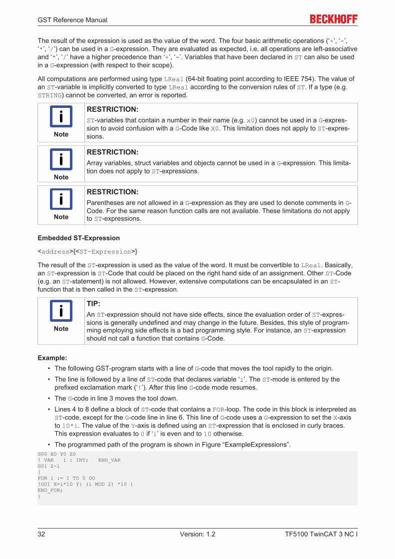
Example:• The following GST-program starts with a line of G-code that moves the tool rapidly to the origin.• The line is followed by a line of ST-code that declares variable ‘i’. The ST-mode is entered by the
prefixed exclamation mark (‘!’). After this line G-code mode resumes.• The G-code in line 3 moves the tool down.• Lines 4 to 8 define a block of ST-code that contains a FOR-loop. The code in this block is interpreted asST-code, except for the G-code line in line 6. This line of G-code uses a G-expression to set the X-axisto 10*i. The value of the Y-axis is defined using an ST-expression that is enclosed in curly braces.This expression evaluates to 0 if ‘i’ is even and to 10 otherwise.
• The programmed path of the program is shown in Figure “ExampleExpressions”.G00 X0 Y0 Z0! VAR i : INT; END_VARG01 Z-1{FOR i := 1 TO 5 DO!G01 X=i*10 Y{ (i MOD 2) *10 }END_FOR;}
GST Reference Manual
TF5100 TwinCAT 3 NC I 33Version: 1.2
10 20 30 40 50
0
0
10
20
-10-10 60
X
Y
Figure “ExampleExpressions”.
Suppression of G-Code Blocks
/<n> <G-Code block>
The execution of a G-Code block can be suppressed conditionally. If ‘/<n>’ is prefixed and the n-th bit in aninternal disable mask is set, the block is suppressed (not executed). The disable mask can be set by thePLC and by the ST-function disableMaskSet. If n is omitted, it has 0 value by default. [See sectionSuppression of G-Code Blocks [} 74].]
3.4 G-Code (DIN 66025)
3.4.1 Comments
DIN 66025 Comment
<g-code> ( <comment> ) <g-code>
Text that is enclosed in round parentheses is treated as comment in G-Code (according to DIN 66025). Thecomment must not include further parentheses.
Example:
The following example demonstrates the notation of comments in G-Code.N10 G01 (activate linear interpolation) X10 (set X-coordinate to10)(the next block results in a semicircle with center pointX10 Y10)N20 G02 (activate clockwise interpolation) Y20 U10 (radius is 10)
Line Comment
<g-code> // <comment>
Text between ‘//’ and the end of line is treated as a comment in G-Code.
Example:
The following example demonstrates the notation of line comments in G-Code.N10 G01 X10 // perform a linear movement to X10 Y0// the next block results in a semicircle with center point X10 Y10N20 G02 Y20 U10
GST Reference Manual
TF5100 TwinCAT 3 NC I34 Version: 1.2
3.4.2 Codes
D
D<v>
Select tool v. The new tool applies to its own block and all succeeding blocks until a new tool is selected.Tool 0 is special. Its selection deactivates any tool compensation. Tool 0 can be regarded as tool where alltool parameters are set to zero. It is selected by default.
Example:
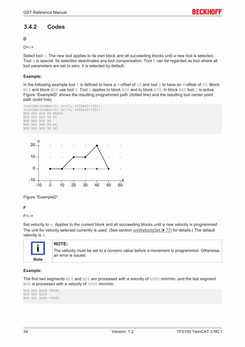
In the following example tool 1 is defined to have a Y-offset of 10 and tool 2 to have an Y-offset of 20. BlockN10 and block N50 use tool 0. Tool 1 applies to block N20 and to block N30. In block N40 tool 2 is active.Figure “ExampleD” shows the resulting programmed path (dotted line) and the resulting tool center pointpath (solid line).!toolSet(index:=1, nr:=1, offsetY:=10);!toolSet(index:=2, nr:=2, offsetY:=20);N10 G01 X10 Y0 F6000N20 G01 X20 Y0 D1N30 G01 X30 Y0N40 G01 X40 Y0 D2N50 G01 X50 Y0 D0
10 20 30 40 50
0
0
10
20
-10-10 60
X
Y
Figure “ExampleD”.
F
F<v>
Set velocity to v. Applies to the current block and all succeeding blocks until a new velocity is programmed.The unit for velocity selected currently is used. (See section unitVelocitySet [} 77] for details.) The defaultvelocity is 0.
Note
NOTE:The velocity must be set to a nonzero value before a movement is programmed. Otherwise,an error is issued.
Example:
The first two segments N10 and N20 are processed with a velocity of 6000 mm/min, and the last segmentN30 is processed with a velocity of 3000 mm/min.N10 G01 X100 F6000N20 G01 X200N30 G01 X300 F3000

GST Reference Manual
TF5100 TwinCAT 3 NC I 35Version: 1.2
G00
Set the interpolation mode to “rapid, linear”. The interpolation mode applies to this block and all succeedingblocks until it is reset by G01, G02 or G03. G00 is the default interpolation mode.
If G00 is active, programming of a point (see X) will result in a linear geometry segment that is processedwith maximum velocity. The programmed velocity is not considered. G00 is typically used to position the tool.For machining G01 should be used, which considers the programmed velocity.
Note
NOTE:G01, G02, G03, G04, G58 and G59 are mutually exclusive. They must not be programmedin a common block.
Example:
The resulting path of the following example is shown in Figure “ExampleG00”. The first block N10 rapidlymoves the tool to position X20, Y10, Z30. The resulting geometry segment is a line in space. The orientationremains unchanged. The second block N20 performs a rapid movement to X50, Y10, Z30. There is no needto denote G00 in this line, since interpolation is modal.N10 G00 X20 Y10 Z30N20 X50
10 20 30 40 50
0
0
10
20
-10-10 60
X
Y
Z=30
Z=0rapid
rapid Z=30
Figure “ExampleG00”.
G01
Set the interpolation mode to “linear”. This interpolation mode is like G00, except that the path is machinedwith the programmed velocity. (See F.) The interpolation mode applies to this block and all succeedingblocks until it is reset by G00, G02 or G03.
G02
Set the interpolation mode to “circular/helical, clockwise”. The interpolation mode applies to this block and allsucceeding blocks until it is reset by G00, G01 or G03. If G02 is active, programming of a point will result in acircular (or helical) arc that is machined with the current velocity. (See F [} 34].) In the following, a circular arcis regarded. The helical arc is covered later.
A circular arc starts at the current point and ends at the programmed point. It rotates around the working-plane normal (PCS, i.e. program coordinate system) in the center point. The center point can be definedusing Centerpoint Programming [} 35] or using Radius Programming [} 36].
Centerpoint Programming
For Centerpoint Programming the center is defined relative to the starting-point using the I,J,K parameters.The center point is the sum of the starting-point and the vector [I,J,K]. The I,J,K parameters areoptional and have 0 value by default. If the starting-point and the endpoint are equal with respect to theworkingplane, a full circle will be emitted.
GST Reference Manual
TF5100 TwinCAT 3 NC I36 Version: 1.2
Note
CONSTRAINT:The radius at the starting-point and at the endpoint must be equal. However, small devia-tions are allowed and corrected automatically. (See centerpointCorrectionSet [} 69].)
Note
CONSTRAINT:The center point must not be equal to the starting-point or endpoint.
Radius Programming
For Radius Programming the center point is derived from the radius that is given by the U parameter.Typically, there are two arcs of a given radius that lead from the starting-point to the endpoint. If the radius ispositive, the shorter one is used, otherwise the longer one is chosen. Apart from that, the absolute value ofthe radius is regarded by the interpreter.
Note
CONSTRAINT:Radius Programming can by its nature not be used to program a full circle. This curvaturecan be programmed by Centerpoint Programming.
Note
CONSTRAINT:The radius must not be zero.
Note
CONSTRAINT:The radius must not be smaller than half of the distance between starting-point and end-point with respect to the workingplane.
Helical
If the starting-point and endpoint do not lie in a plane that is parallel to the workingplane, a helical movementis performed.
Note
TIP: moveCircle3DThe ST-function moveCircle3D is a more powerful way to define a circle or helix. It covers3D-arcs and multiturn circles.
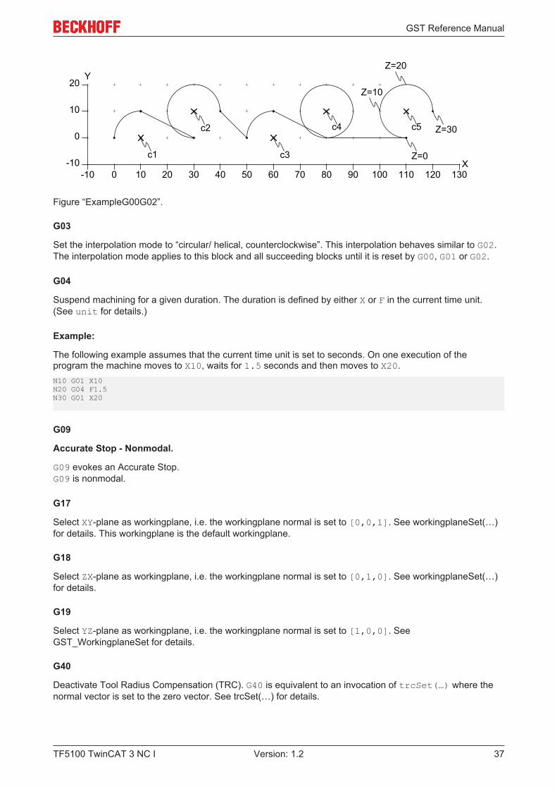
Example:
The following example results in the path that is shown in Figure “ExampleG00G02”. The block N10 usesRadius Programming to define a clockwise arc from X0 Y0 to X10 Y10 with radius 10. Because the radius ispositive, the center point c1 of the shorter arc is chosen. In block N30 the center point c2 of the longer arc isused because the radius is negative. The block N50 uses Centerpoint Programming, where the centerc3=[60,0,0] is the sum of the starting-point [50,0,0] and [I,J,K]=[10,0,0]. The block N70 definesa full circle with center point C04 because the starting-point and endpoint are equal. The block N90 defines ahelical arc with center point C05 and height 30 (in Z-direction).N10 G02 X10 Y10 U10N20 G00 X30 Y0N30 G02 X40 Y10 U-10N40 G00 X50 Y0N50 G02 X60 Y10 I10N60 G00 X80 Y0N70 G02 J10N80 G00 X110 Y0N90 G02 J10 X120 Y10 Z30
GST Reference Manual
TF5100 TwinCAT 3 NC I 37Version: 1.2
10 20 30 40 50
0
0
10
20
-10-10 60
X
Y
70 80 90 100 110 120 130
c1
c2
c3
c4
Z=0
c5
Z=10
Z=20
Z=30
Figure “ExampleG00G02”.
G03
Set the interpolation mode to “circular/ helical, counterclockwise”. This interpolation behaves similar to G02.The interpolation mode applies to this block and all succeeding blocks until it is reset by G00, G01 or G02.
G04
Suspend machining for a given duration. The duration is defined by either X or F in the current time unit.(See unit for details.)
Example:
The following example assumes that the current time unit is set to seconds. On one execution of theprogram the machine moves to X10, waits for 1.5 seconds and then moves to X20.N10 G01 X10N20 G04 F1.5N30 G01 X20
G09
Accurate Stop - Nonmodal.
G09 evokes an Accurate Stop.G09 is nonmodal.
G17
Select XY-plane as workingplane, i.e. the workingplane normal is set to [0,0,1]. See workingplaneSet(…)for details. This workingplane is the default workingplane.
G18
Select ZX-plane as workingplane, i.e. the workingplane normal is set to [0,1,0]. See workingplaneSet(…)for details.
G19
Select YZ-plane as workingplane, i.e. the workingplane normal is set to [1,0,0]. SeeGST_WorkingplaneSet for details.
G40
Deactivate Tool Radius Compensation (TRC). G40 is equivalent to an invocation of trcSet(…) where thenormal vector is set to the zero vector. See trcSet(…) for details.

GST Reference Manual
TF5100 TwinCAT 3 NC I38 Version: 1.2
G41
Activate tool radius compensation (TRC). After activation the programmed path is shifted left by the radius ofthe currently selected tool. (See D [} 34].)
More precisely, G41 is equivalent to an invocation of trcSet(…), where
• normal is set to the negated normal of the current working-plane, multiplied by the radius of thecurrently selected tool,
• offset is set to the value defined by trcOffsetSet(…),• radius and angle for approach and depart are set to the values defined bytrcApproachDepartSet(…),
• limit is set to the value defined by trcLimitSet(…).
See trcSet(…) for details.
Note
NOTE:On activation, a tool with a nonzero index must be selected.
Example:
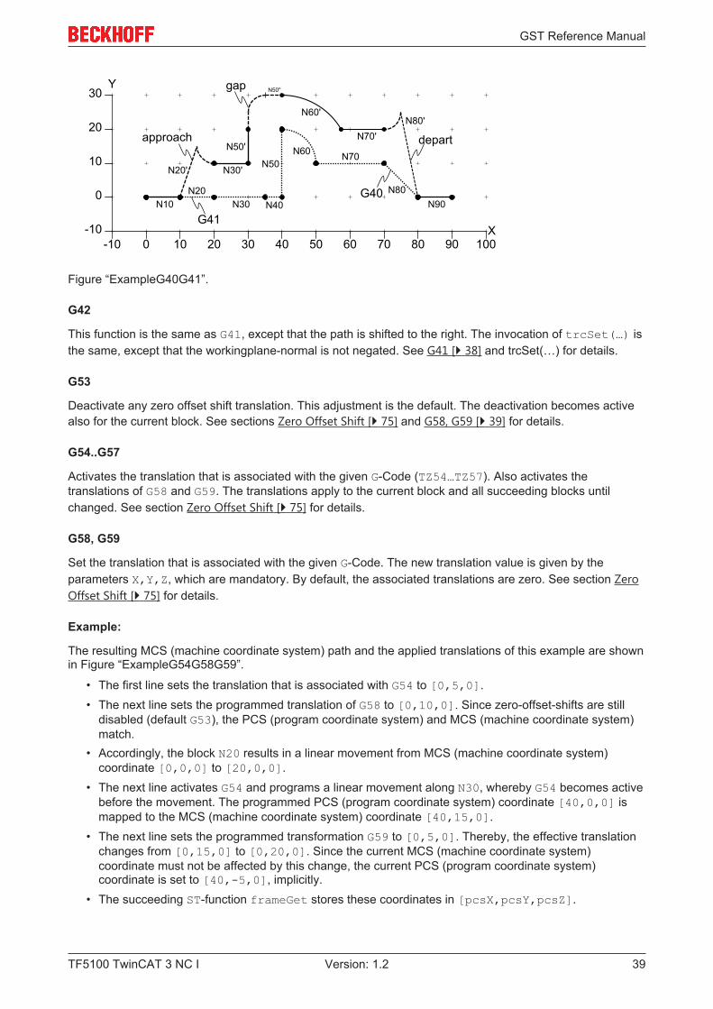
The following example demonstrates the activation and deactivation of tool radius compensation. Theprogrammed path (dotted line) and the compensated path (solid/ dashed line) are shown inFigure “ExampleG40G41”.
• The first line of the GST program sets the offset parameter to 5 mm. Therefore, the adjacentsegments of a gap are extended by 5 mm. The remaining gap is closed by a circular arc.
• The second line defines the approach and depart behavior to use a circular arc with a radius of 5 mmand an angle of 90 degree.
• The third line defines tool 1 to have a radius of 10.• Block N10 describes a linear movement to [10,0,0].• The next block N20 selects tool 1 and activates tool radius compensation, where D1 comes into effect
before G40 is processed and G40 is active before X20 is processed. Therefore, the end of segmentN20 is subject to TRC (tool radius compensation). The linear movement from the end of segment N10to the end of segment N20 in the programmed path is substituted by an approach-segment (dottedline) from the end of N10 to the end of N20' in the compensated path.
• In the next three lines a linear movement along N30, N40 and N50 is programmed. Since segment N40would result in a collision, it is eliminated from the compensated path.
• In the next line a circular arc along N60 is programmed. The gap between the end of N50' and thebeginning of N60' is closed as described earlier.
• The line along N70 is the last segment that is subject to TRC (tool radius compensation), since itsdeactivation becomes active before the end of N80. The line along N80 is replaced by the depart-segment N80', similarly to the approach-segment.
!trcOffsetSet(offset:=5);!trcApproachDepartSet(approachRadius:=5, approachAngle:=90, departRadius:=5, departAngle:=90);!toolSet(index:=1, tooltype:=tooltypeMill, radius:=10);N10 G01 X10N20 X20 G41 D1N30 X35N40 X40N50 Y20N60 G02 X50 Y10 U10N70 G01 X70N80 X80 Y0 G40N90 X90
GST Reference Manual
TF5100 TwinCAT 3 NC I 39Version: 1.2
10 20 30 40 50
0
0
10
20
-10-10 60
X
Y
70 80 90 100
30
G41
G40
approach
gap
depart
N10N20
N30 N40
N50N20'
N60 N70
N80
N80'
N30'
N50'
N50''
N60'
N70'
N90
Figure “ExampleG40G41”.
G42
This function is the same as G41, except that the path is shifted to the right. The invocation of trcSet(…) isthe same, except that the workingplane-normal is not negated. See G41 [} 38] and trcSet(…) for details.
G53
Deactivate any zero offset shift translation. This adjustment is the default. The deactivation becomes activealso for the current block. See sections Zero Offset Shift [} 75] and G58, G59 [} 39] for details.
G54..G57
Activates the translation that is associated with the given G-Code (TZ54…TZ57). Also activates thetranslations of G58 and G59. The translations apply to the current block and all succeeding blocks untilchanged. See section Zero Offset Shift [} 75] for details.
G58, G59
Set the translation that is associated with the given G-Code. The new translation value is given by theparameters X,Y,Z, which are mandatory. By default, the associated translations are zero. See section ZeroOffset Shift [} 75] for details.
Example:
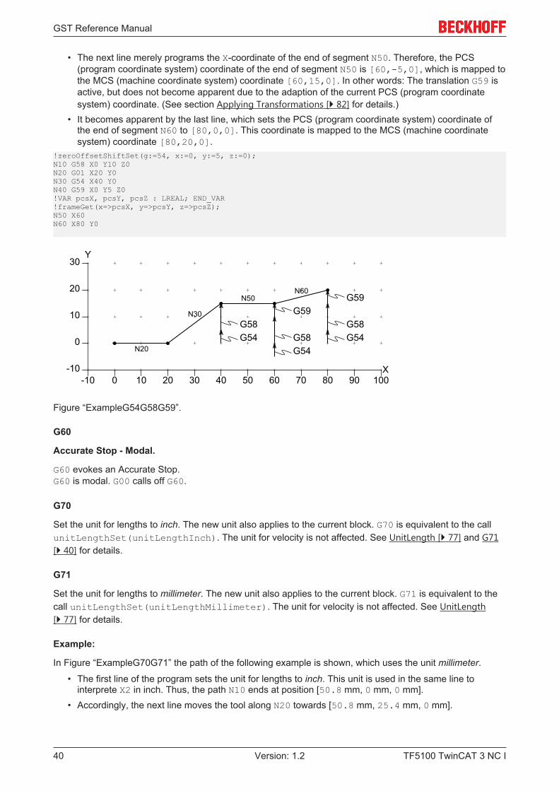
The resulting MCS (machine coordinate system) path and the applied translations of this example are shownin Figure “ExampleG54G58G59”.
• The first line sets the translation that is associated with G54 to [0,5,0].• The next line sets the programmed translation of G58 to [0,10,0]. Since zero-offset-shifts are still
disabled (default G53), the PCS (program coordinate system) and MCS (machine coordinate system)match.
• Accordingly, the block N20 results in a linear movement from MCS (machine coordinate system)coordinate [0,0,0] to [20,0,0].
• The next line activates G54 and programs a linear movement along N30, whereby G54 becomes activebefore the movement. The programmed PCS (program coordinate system) coordinate [40,0,0] ismapped to the MCS (machine coordinate system) coordinate [40,15,0].
• The next line sets the programmed transformation G59 to [0,5,0]. Thereby, the effective translationchanges from [0,15,0] to [0,20,0]. Since the current MCS (machine coordinate system)coordinate must not be affected by this change, the current PCS (program coordinate system)coordinate is set to [40,-5,0], implicitly.
• The succeeding ST-function frameGet stores these coordinates in [pcsX,pcsY,pcsZ].
GST Reference Manual
TF5100 TwinCAT 3 NC I40 Version: 1.2
• The next line merely programs the X-coordinate of the end of segment N50. Therefore, the PCS(program coordinate system) coordinate of the end of segment N50 is [60,-5,0], which is mapped tothe MCS (machine coordinate system) coordinate [60,15,0]. In other words: The translation G59 isactive, but does not become apparent due to the adaption of the current PCS (program coordinatesystem) coordinate. (See section Applying Transformations [} 82] for details.)
• It becomes apparent by the last line, which sets the PCS (program coordinate system) coordinate ofthe end of segment N60 to [80,0,0]. This coordinate is mapped to the MCS (machine coordinatesystem) coordinate [80,20,0].
!zeroOffsetShiftSet(g:=54, x:=0, y:=5, z:=0);N10 G58 X0 Y10 Z0N20 G01 X20 Y0N30 G54 X40 Y0N40 G59 X0 Y5 Z0!VAR pcsX, pcsY, pcsZ : LREAL; END_VAR!frameGet(x=>pcsX, y=>pcsY, z=>pcsZ);N50 X60N60 X80 Y0
10 20 30 40 50
0
0
10
20
-10-10 60
X
Y
70 80 90 100
30
N20
N30
N50N60
G54G58
G54G58
G59
G54G58
G59
Figure “ExampleG54G58G59”.
G60
Accurate Stop - Modal.
G60 evokes an Accurate Stop.G60 is modal. G00 calls off G60.
G70
Set the unit for lengths to inch. The new unit also applies to the current block. G70 is equivalent to the callunitLengthSet(unitLengthInch). The unit for velocity is not affected. See UnitLength [} 77] and G71[} 40] for details.
G71
Set the unit for lengths to millimeter. The new unit also applies to the current block. G71 is equivalent to thecall unitLengthSet(unitLengthMillimeter). The unit for velocity is not affected. See UnitLength[} 77] for details.
Example:
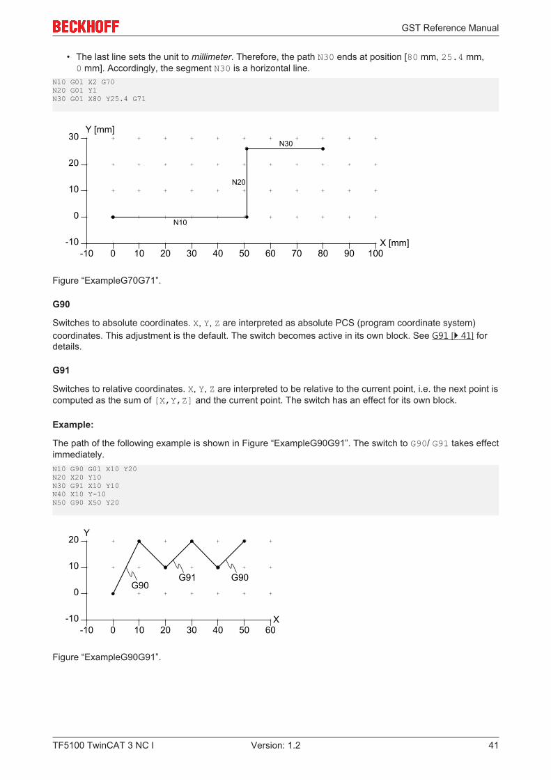
In Figure “ExampleG70G71” the path of the following example is shown, which uses the unit millimeter.
• The first line of the program sets the unit for lengths to inch. This unit is used in the same line tointerprete X2 in inch. Thus, the path N10 ends at position [50.8 mm, 0 mm, 0 mm].
• Accordingly, the next line moves the tool along N20 towards [50.8 mm, 25.4 mm, 0 mm].
GST Reference Manual
TF5100 TwinCAT 3 NC I 41Version: 1.2
• The last line sets the unit to millimeter. Therefore, the path N30 ends at position [80 mm, 25.4 mm,0 mm]. Accordingly, the segment N30 is a horizontal line.
N10 G01 X2 G70N20 G01 Y1N30 G01 X80 Y25.4 G71
10 20 30 40 50
0
0
10
20
-10-10 60
X [mm]
Y [mm]
70 80 90 100
30
N20
N30
N10
Figure “ExampleG70G71”.
G90
Switches to absolute coordinates. X, Y, Z are interpreted as absolute PCS (program coordinate system)coordinates. This adjustment is the default. The switch becomes active in its own block. See G91 [} 41] fordetails.
G91
Switches to relative coordinates. X, Y, Z are interpreted to be relative to the current point, i.e. the next point iscomputed as the sum of [X,Y,Z] and the current point. The switch has an effect for its own block.
Example:
The path of the following example is shown in Figure “ExampleG90G91”. The switch to G90/ G91 takes effectimmediately.N10 G90 G01 X10 Y20N20 X20 Y10N30 G91 X10 Y10N40 X10 Y-10N50 G90 X50 Y20
10 20 30 40 50
0
0
10
20
-10-10 60
X
Y
G90G90G91
Figure “ExampleG90G91”.
GST Reference Manual
TF5100 TwinCAT 3 NC I42 Version: 1.2
G700
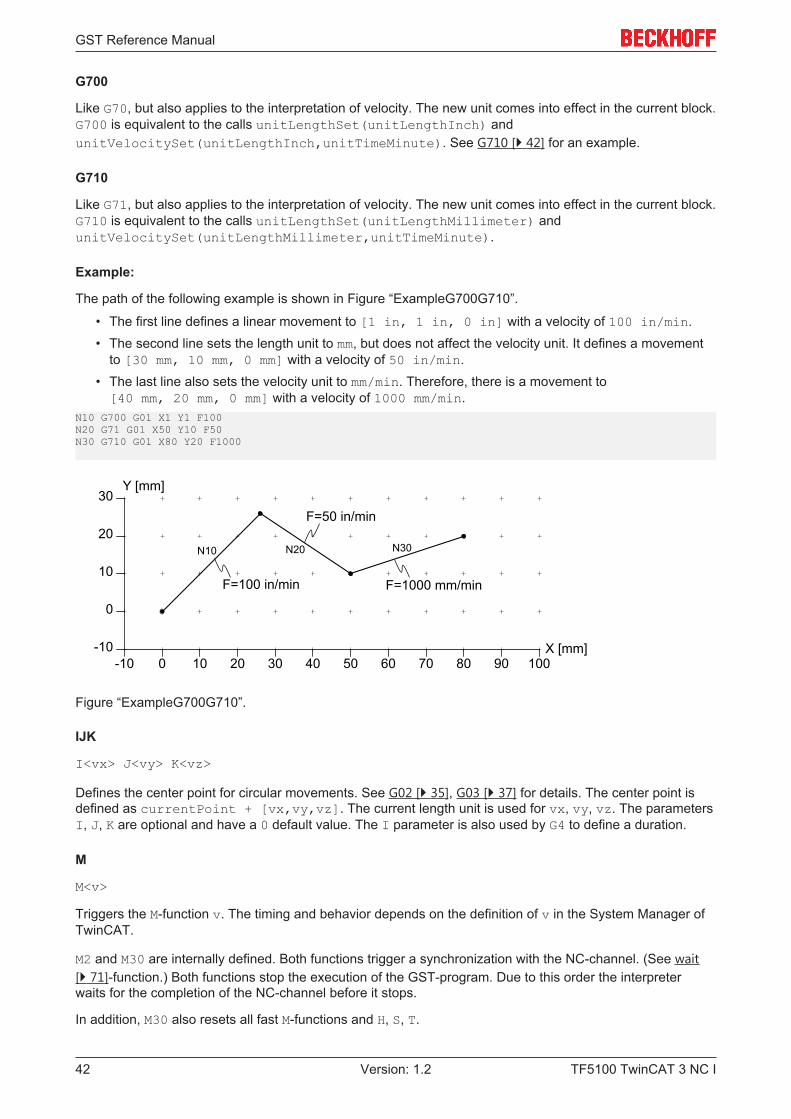
Like G70, but also applies to the interpretation of velocity. The new unit comes into effect in the current block.G700 is equivalent to the calls unitLengthSet(unitLengthInch) andunitVelocitySet(unitLengthInch,unitTimeMinute). See G710 [} 42] for an example.
G710
Like G71, but also applies to the interpretation of velocity. The new unit comes into effect in the current block.G710 is equivalent to the calls unitLengthSet(unitLengthMillimeter) andunitVelocitySet(unitLengthMillimeter,unitTimeMinute).
Example:
The path of the following example is shown in Figure “ExampleG700G710”.
• The first line defines a linear movement to [1 in, 1 in, 0 in] with a velocity of 100 in/min.• The second line sets the length unit to mm, but does not affect the velocity unit. It defines a movement
to [30 mm, 10 mm, 0 mm] with a velocity of 50 in/min.• The last line also sets the velocity unit to mm/min. Therefore, there is a movement to[40 mm, 20 mm, 0 mm] with a velocity of 1000 mm/min.
N10 G700 G01 X1 Y1 F100N20 G71 G01 X50 Y10 F50N30 G710 G01 X80 Y20 F1000
10 20 30 40 50
0
0
10
20
-10-10 60
X [mm]
Y [mm]
70 80 90 100
30
N20 N30N10
F=100 in/min
F=50 in/min
F=1000 mm/min
Figure “ExampleG700G710”.
IJK
I<vx> J<vy> K<vz>
Defines the center point for circular movements. See G02 [} 35], G03 [} 37] for details. The center point isdefined as currentPoint + [vx,vy,vz]. The current length unit is used for vx, vy, vz. The parametersI, J, K are optional and have a 0 default value. The I parameter is also used by G4 to define a duration.
M
M<v>
Triggers the M-function v. The timing and behavior depends on the definition of v in the System Manager ofTwinCAT.
M2 and M30 are internally defined. Both functions trigger a synchronization with the NC-channel. (See wait[} 71]-function.) Both functions stop the execution of the GST-program. Due to this order the interpreterwaits for the completion of the NC-channel before it stops.
In addition, M30 also resets all fast M-functions and H, S, T.
GST Reference Manual
TF5100 TwinCAT 3 NC I 43Version: 1.2
Note
NOTE:There must not be more than one M-function of type handshake in a block.
Note
NOTE:The M-functions M2 and M30 do not have to be defined by the user in the System Managerof TwinCAT.
Example:
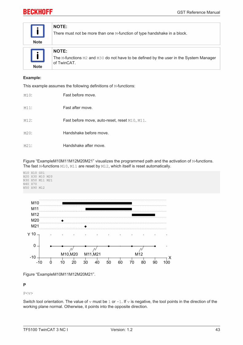
This example assumes the following definitions of M-functions:
M10: Fast before move.
M11: Fast after move.
M12: Fast before move, auto-reset, reset M10, M11.
M20: Handshake before move.
M21: Handshake after move.
Figure “ExampleM10M11M12M20M21” visualizes the programmed path and the activation of M-functions.The fast M-functions M10, M11 are reset by M12, which itself is reset automatically.N10 X10 G01N20 X30 M10 M20N30 X50 M11 M21N40 X70N50 X90 M12
M10,M20 M11,M21 M12
10 20 30 40 50
0
0
10
-10-10 60
X
Y
70 80 90 100
M10M11
M20M21
M12
Figure “ExampleM10M11M12M20M21”.
P
P<v>
Switch tool orientation. The value of v must be 1 or -1. If v is negative, the tool points in the direction of theworking plane normal. Otherwise, it points into the opposite direction.
GST Reference Manual
TF5100 TwinCAT 3 NC I44 Version: 1.2
Example:
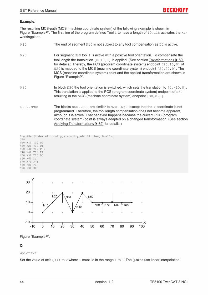
The resulting MCS-path (MCS: machine coordinate system) of the following example is shown inFigure “ExampleP”. The first line of the program defines Tool 1 to have a length of 10. G18 activates the XZ-workingplane.
N10: The end of segment N10 is not subject to any tool compensation as D0 is active.
N20: For segment N20 tool 1 is active with a positive tool orientation. To compensate thetool length the translation [0,10,0] is applied. (See section Transformations [} 80]for details.) Thereby, the PCS (program coordinate system) endpoint [20,10,0] ofN20 is mapped to the MCS (machine coordinate system) endpoint [20,20,0]. TheMCS (machine coordinate system) point and the applied transformation are shown inFigure “ExampleP”.
N30: In block N30 the tool orientation is switched, which sets the translation to [0,-10,0].This translation is applied to the PCS (program coordinate system) endpoint of N30resulting in the MCS (machine coordinate system) endpoint [30,0,0].
N20..N90: The blocks N60..N90 are similar to N20..N50, except that the Y-coordinate is notprogrammed. Therefore, the tool length compensation does not become apparent,although it is active. That behavior happens because the current PCS (programcoordinate system) point is always adapted on a changed transformation. (See sectionApplying Transformations [} 82] for details.)
!toolSet(index:=1, tooltype:=tooltypeDrill, length:=10);G18N10 X10 Y10 D0N20 X20 Y10 D1N30 X30 Y10 P-1N40 X40 Y10 P1N50 X50 Y10 D0N60 X60 D1N70 X70 P-1N80 X80 P1N90 X90 D0
10 20 30 40 50
0
0
10
20
-10-10 60
X
Y
70 80 90 100
30
N10
N20 N30
N40
N50
N60 N70 N80 N90
Figure “ExampleP”.
Q
Q<i>=<v>
Set the value of axis Q<i> to v where i must lie in the range 1 to 5. The Q-axes use linear interpolation.
GST Reference Manual
TF5100 TwinCAT 3 NC I 45Version: 1.2
Note
NOTE:The address letters Q and R are handled in a special way for historical reasons.
Note
CONSTRAINT:The address Q<i> has to be followed by a G-expression or by an ST-expression. The G-word Q1100 is invalid. Use Q1=100, instead.
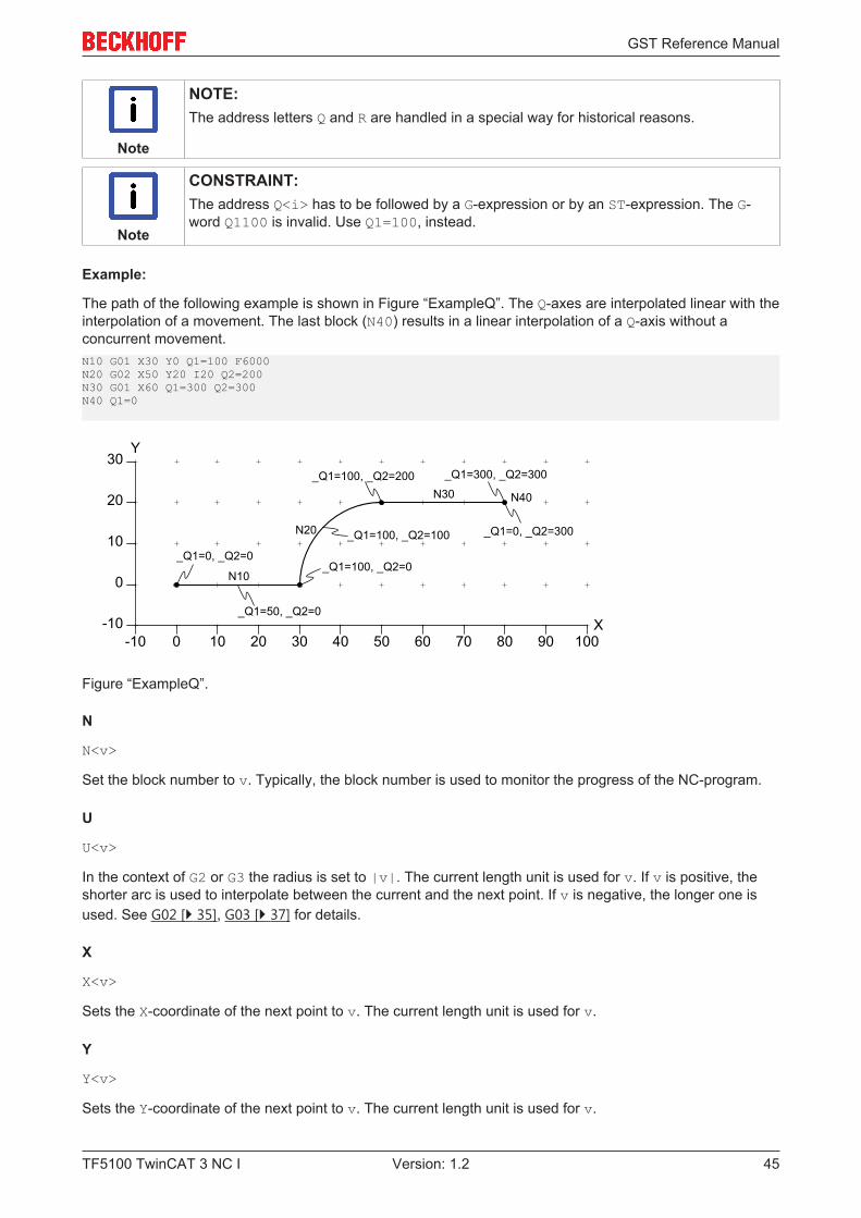
Example:
The path of the following example is shown in Figure “ExampleQ”. The Q-axes are interpolated linear with theinterpolation of a movement. The last block (N40) results in a linear interpolation of a Q-axis without aconcurrent movement.N10 G01 X30 Y0 Q1=100 F6000N20 G02 X50 Y20 I20 Q2=200N30 G01 X60 Q1=300 Q2=300N40 Q1=0
10 20 30 40 50
0
0
10
20
-10-10 60
X
Y
70 80 90 100
30
N10
N20
N30 N40
_Q1=0, _Q2=0_Q1=100, _Q2=0
_Q1=100, _Q2=200 _Q1=300, _Q2=300
_Q1=50, _Q2=0
_Q1=100, _Q2=100 _Q1=0, _Q2=300
Figure “ExampleQ”.
N
N<v>
Set the block number to v. Typically, the block number is used to monitor the progress of the NC-program.
U
U<v>
In the context of G2 or G3 the radius is set to |v|. The current length unit is used for v. If v is positive, theshorter arc is used to interpolate between the current and the next point. If v is negative, the longer one isused. See G02 [} 35], G03 [} 37] for details.
X
X<v>
Sets the X-coordinate of the next point to v. The current length unit is used for v.
Y
Y<v>
Sets the Y-coordinate of the next point to v. The current length unit is used for v.
GST Reference Manual
TF5100 TwinCAT 3 NC I46 Version: 1.2
Z
Z<v>
Sets the Z-coordinate of the next point to v. The current length unit is used for v.
A
A<v>
Sets the A-angle of the next orientation to v. The current angle unit is used for v.
B
B<v>
Sets the B-angle of the next orientation to v. For v the current angle unit is used.
C
C<v>
Sets the C-angle of the next orientation to v. For v the current angle unit is used.
3.4.3 Execution OrderA block (line of G-code) consists of a sequence of words. The programmed order of words is not consideredby the GST interpreter. Instead, the following execution order is obeyed that consists of 7 sequential anddependent steps.
1. Reference System N* Set block number.
G17..G19 Selection of a workingplane.
G70, G71, G700, G710 Selection of a unit.
G90, G91 Selection of absolute/ incrementalprogramming.
D*, P* Selection of a tool and its orientation.
2. Configuration G40..G42 (De-)activation of Tool RadiusCompensation.
G53..G59 Selection and programming of zero offsetshift.
F* Set velocity.
3. M-Function Pre M* M-functions that are configured as “before”.
4. Parameter to PLC H*, S*, T*
GST Reference Manual
TF5100 TwinCAT 3 NC I 47Version: 1.2
5. Movement Q*, G00..G03 Movement to a point.
G09, G60 Activation of accurate stop.
6. Wait G04 Wait for a given duration.
7. M-Function Post M* M-functions that are configured as “after”.
The first step sets up the reference system. The second step configures following movements. Note that thesecond step may depend on the first one. E.g. the programmed velocity (F) considers a velocity unit (G700)that is programmed in the same block. Step three and the following steps perform actions like a movement.
3.4.4 Mutual Exclusive G-CodesCertain combinations of G-Codes must not be programmed in the same block (line of G-Code). Suchconflicting G-Codes typically set state variables to contradictory values (e.g. set length unit to mm and toinch). There are also combinations that use the same parameters and therefore must not be programmedin the same block (e.g. G58 and G59). Below is a list of groups of G-Codes. G-Codes that belong to the samegroup are in conflict.
• G00, G01, G02, G03, G04, G58, G59Interpolations and programmed zero-offset-shift.
• G70, G71, G700, G710Set unit for length and speed.
• G90, G91Set absolute/ relative programming.
• G53, G54, G55, G56, G57Deactivate/ select zero-offset-shift.
• G40, G41, G42Deactivate/ activate Tool Radius Compensation.
• G17, G18, G19Select workingplane.
3.5 ST - Structured Text (IEC 61131-3)
3.5.1 Comments
Line Comment
<st-code> // <comment>
Text between ‘//’ and the end of line is treated as comment in ST-Code.
Example:{VAR i : INT; // this variable is primarily used in FOR-loops for countingEND_VAR}
GST Reference Manual
TF5100 TwinCAT 3 NC I48 Version: 1.2
/* */ Comment<st-code> /* <comment><comment> */ <st-code>
Text between ‘/*’ and ‘*/’ is treated as comment in ST. This type of comment may be nested up to a depthof 3. The ‘/*…*/’-style comment may appear anywhere between literals, keywords, identifiers and specialsymbols. It may also contain G-Code lines.
Example:
The following example demonstrates the notation of comments in ST-Code. The first comment is placedwithin a variable declaration. The second comment encloses an entire ST-loop. The comment containsfurther comments and a G-Code line, which itself contains a G-Code comment.{VAR i /* used for counting */ : INT; END_VAR
/* The following loop is commented out.FOR i := 0 TO 10 DO /* zigzag pattern */ ! G01 (linear interpolation) X=i Y{i MOD 2} // end of loopEND_FOR;*/}
(* *) Comment<st-code> (* <comment><comment> *) <st-code>
Text between ‘(*’ and ‘*)’ is treated as comment in ST. This type of comment may be nested up to a depthof 3. It is similar to the /*…*/-style comment.
3.5.2 Literals
Integer Literals
Decimal 18
Binary 2#10010
Octal 8#22
Hexadecimal 16#12
The same integer value in decimal, binary, octal and hexadecimal notation.
Real Literals
Notation of real values
1.0
1.602E-19
Boolean Literals
Notation of Boolean values
GST Reference Manual
TF5100 TwinCAT 3 NC I 49Version: 1.2
0
1
TRUE
FALSE
Typed Literals
<typename>#<literal>
Typed literals where typename is a native type (e.g. Word or LReal) or an enumeration type (to avoidambiguities).
Typing of literals is typically not necessary in GST, since the interpreter implements a decent typesystem thathandles untyped literals properly. There are a few exceptions where the type of a literal is significant forsemantics, like in the following example.
Example:
The first assignment assigns the value 16#80 to w, whereas the second one assigns the value 16#8000 tow.{VAR w: word; END_VARw := ror(BYTE#1,1);w := ror(WORD#1,1);}
String Literals
"abc"
'abc'
Notation of a 2-byte and a 1-byte string, respectively. Note that there is no implicit conversion between bothtypes. The following escape-sequences can be used within both types of literals:
$L line feed
$N newline
$P form feed
$R carriage return
$t tab
$' or $" quotes
$<2 or 4 hexadecimal digits> character of given code
.
Duration Literals
T#[+/-]<value><unit>[…]<value><unit>
TIME#[+/-] <value><unit>[…]<value><unit>
GST Reference Manual
TF5100 TwinCAT 3 NC I50 Version: 1.2
LT#[+/-]<value><unit>[…]<value><unit>
LTIME#[+/-]<value><unit>[…]<value><unit>
Time literals of type TIME or LTIME. The literal consists of an optional sign (+/-) and a sequence of value/unit pairs. Value must be an integer, except for the last one that may also be a floating point number.Values must not be negative and may be arbitraryly large. Units must appear in the following order.
d day
h hour
m minute
s second
ms millisecond
us microsecond
ns nanosecond
An arbitrary subset of units may be used in a literal. For instance, the literal T#1d15ms1500.01us is valid.
Date Literals
DATE#<yyyy>-<mm>-<dd>
D#<yyyy>-<mm>-<dd>
LDATE#<yyyy>-<mm>-<dd>
LD#<yyyy>-<mm>-<dd>
Date literal of type DATE or LDATE. The literal is interpreted as UTC, i.e. timezone, daylight saving time andleap seconds are not considered. The year must not be smaller than 1970. The values yyyy, mm and ddhave to be integer values, i.e. D#1980-20-10 is a valid date literal, for example.
Time-of-Day Literals
TIME_OF_DAY#<hh>:<mm>:<ss>
TOD#<hh>:<mm>:<ss>
LTIME_OF_DAY#<hh>:<mm>:<ss>
LTOD#<hh>:<mm>:<ss>
Time-of-day literal of type TOD or LTOD. The literal is interpreted as UTC, i.e. timezone, daylight saving timeand leap seconds are not considered. hh and mm must be integer values. ss may be an integer or afloatingpoint number, i.e. TOD#7:30:3.1415 is a valid literal, for example.
Date-and-Time Literals
DATE_AND_TIME#<yyyy>-<mm>-<dd>-<hh>:<mm>:<ss>
DT#<yyyy>-<mm>-<dd>-<hh>:<mm>:<ss>
LDATE_AND_TIME#<yyyy>-<mm>-<dd>-<hh>:<mm>:<ss>
GST Reference Manual
TF5100 TwinCAT 3 NC I 51Version: 1.2
LDT#<yyyy>-<mm>-<dd>-<hh>:<mm>:<ss>
Date-and-time literal of type DT or LDT. The literal is interpreted as UTC, i.e. timezone, daylight saving timeand leap seconds are not considered. This literal is a combination of the date literal and the time-of-dayliteral. Analogously, the corresponding rules for these two parts apply.
3.5.3 Native Data Types
Bitstring Types
BOOL, BYTE, WORD, DWORD, LWORD
Bitstring types of 1, 8, 16, 32 and 64 bit. Implicit conversion from left to right using zero extension.
Unsigned Integer Types
USINT, UINT, UDINT, ULINT
Unsigned integer types of 8, 16, 32 and 64 bit. Implicit conversion from left to right preserving the value.
Signed Integer Types
SINT, INT, DINT, LINT
Signed integer types of 8, 16, 32 and 64 bit. Implicit conversion from left to right preserving the value. Anunsigned type of n bit is also implicitly converted to a signed type of m bit where the relation m > n musthold. There is no implicit conversion between bitstring types and integer types.
String Types
string[<length>]
wstring[<length>]
1-byte and 2-byte strings of given length. If length is omitted, it has 255 as default value.
Character Types
char
wchar
Single 1-byte and 2-byte character of a string. It can be implicitly converted to a string.
Time-Related Types
TIME, LTIME
DATE, LDATE
TIME_OF_DAY, TOD, LTIME_OF_DAY, LTOD
DATE_AND_TIME, DT, LDATE_AND_TIME, LDT
Datatypes for duration, date and time. Internally, all values of these types are represented with a granularityof 1 nanosecond. Values of date-related types represent the number of nanoseconds since 1.1.1970(UTC). Leapseconds are ignored. Implicit conversion is allowed from a non-L type to an L type, e.g. fromTIME to LTIME.
GST Reference Manual
TF5100 TwinCAT 3 NC I52 Version: 1.2
3.5.4 Userdefined Types
Derived Types
TYPE
<typeName>: <typeName> := <defaultValue>;
END_TYPE
Definition of a new type as an alias to an existing type. The default value is optional.
Enumeration Types
TYPE
<typeName> : (<enumValue>, …, <enumValue>) := <defaultValue>;
END_TYPE
Definition of an enumeration type. The default value is optional.
Enumeration Types with Defined Values
TYPE
<typeName> : (<enumValue>:=<integer value>, …,
<enumValue>:=<integer value>) := <defaultValue>;
END_TYPE
Definition of an enumeration type with user-defined values for each element. The default value is optional.
Array Types
TYPE
<typeName>: ARRAY [<from>..<to>,<from>..<to>] OF <typeName> :=
[<defaultValue>, <repetition>(<defaultValue>), …];
END_TYPE
Definition of an array type. The array may be multi-dimensional. The index range is defined for eachdimension. At runtime the boundaries of the array are checked. A boundary violation leads to a runtime-error. The default values are defined in ascending order starting with the last dimension. A value can berepeated by placing it into parentheses prefixed with the number of repetitions. If the number of defineddefault values does not match the array size, initialization is truncated or padded with the default value of theelement type. In either cases a compile-time warning is issued.
Structure Types
TYPE
<typeName>: STRUCT
<memberName>: memberType;
…
END_STRUCT := (<memberName> := <defaultValue>, …);
END_TYPE
GST Reference Manual
TF5100 TwinCAT 3 NC I 53Version: 1.2
Defines a structure type of the given members. Currently, the default value is placed after the type definition.This positional style is a difference to the ST-standard.
Pointer Types
TYPE
<typeName>: REF_TO <basetypeName>;
END_TYPE
Defines a pointer type of the given base type.
3.5.5 Control Structures
IF-THEN-ELSIF-ELSE
IF <condition> THEN
<statements>
ELSIF <condition> THEN
<statements>
ELSE
<statements>
END_IF;
Conditional statement. The ELSIF-branch and ELSE-branch are optional. ELSIF can be repeated arbitrarily.
CASE OF
CASE <expression> OF
<value>, <value>, …, <value>: <statements>
ELSE
<statements>
END_CASE;
The case-list consists of a comma-separated sequence of values or ranges. Only the first matching case isexecuted. The optional ELSE-branch is executed if no case matches.
FOR
FOR <variable> := <expression> TO <expression> BY <expression> DO
<statements>
END_FOR;
Iterates over the given variable in the defined range (including) using the supplied step-size. If the latter isomitted, it has 1 as default value.
WHILE
WHILE <condition> DO
<statements>
GST Reference Manual
TF5100 TwinCAT 3 NC I54 Version: 1.2
END_WHILE;
Pre-checked loop.
REPEAT
REPEAT
<statement>
UNTIL <condition>
END_REPEAT;
Post-checked loop. The break condition is evaluated after performing the <statements> the loop includes.
EXIT
EXIT;
EXIT can be used within loops to leave the loop. If loops are nested, only the innermost loop is left. If thereis no loop surrounding the EXIT keyword, a compile-time error is issued.
3.5.6 Userdefined Functions
Function Definition
FUNCTION <name> : <returntype>
VAR_INPUT
<variable declarations>
END_VAR
VAR_OUTPUT
<variable declarations>
END_VAR
VAR_IN_OUT
<variable declarations>
END_VAR
VAR
<variable declarations>
END_VAR
VAR_EXTERNAL
<variable declarations>
END_VAR
<statements>
END_FUNCTION
Declares a function. Thereafter, it is callable by its name. The declaration of the return type is optional. If it issupplied, the function returns a value of the given type. The return value is defined within the function bodyby an assignment to the function name.
GST Reference Manual
TF5100 TwinCAT 3 NC I 55Version: 1.2
The function may have input, output and in-out parameters. The order of declaration is significant. It is usedfor nonformal calls. Declared variables are only used within the function body. External variables areimported from global scope. Variables and parameters are not persistent, i.e. they do not retain their valuebetween two calls. A function may call itself (recursion).
Nonformal Function Call
<functionname>(<expression>, …, <expression>)
Nonformal function call. The order of expressions must match the number and order of declared parameters.
Formal Function Call
<functionname>(
<inputParamName> := <expression>,
<outputParamName> => <variableName>,
<inputParamName> := <variableName>)
Formal function call. Parameters are identified by their name. If a declared parameter is not listed, it isimplicitly set to its default value.
3.5.7 Standard Functions
3.5.7.1 Type Conversion
Type Conversion (*_TO_*)
<nativeType>_to_<nativeType>(x)
to_<nativeType>(x)
Explicit conversion between the given native types. The second alternative is overloaded for any applicabletype.
For conversion from floatingpoint to integer x is rounded.
3.5.7.2 Arithmetic and Trigonometric
ABS
ABS(x)
Returns the absolute value of x.
The function is overloaded for any integer type and floatingpoint type. The type of x is used as return type.
SQRT
SQRT(x)
Returns the square root of x.
The function is overloaded for any floatingpoint type. The type of x is used as return type.
Note
RESTRICTION:Variable x must not be negative.
GST Reference Manual
TF5100 TwinCAT 3 NC I56 Version: 1.2
LN
LN(x)
Returns the natural logarithm of x, i.e. the logarithm to the base e.
The function is overloaded for any floatingpoint type. The type of x is used as return type.
Note
RESTRICTION:Variable x must be larger than 0.
LOG
LOG(x)
Returns the logarithm of x to the base 10.
The function is overloaded for any floatingpoint type. The type of x is used as return type.
Note
RESTRICTION:Variable x must be larger than 0.
EXP
EXP(x)
Returns e raised to the power of x.
The function is overloaded for any floatingpoint type. The type of x is used as return type.
SIN
SIN(x)
Returns the sine of x where x is expected to be in radians.
The function is overloaded for any floatingpoint type. The type of x is used as return type.
Confer the gSin [} 77] function.
COS
COS(x)
Returns the cosine of x where x is expected to be in radians.
The function is overloaded for any floatingpoint type. The type of x is used as return type.
Confer the gCos [} 77] function.
TAN
TAN(x)
Returns the tangent of x where x is expected to be in radians.
The function is overloaded for any floatingpoint type. The type of x is used as return type.
Confer the gTan [} 77] function.
GST Reference Manual
TF5100 TwinCAT 3 NC I 57Version: 1.2
ASIN
ASIN(x)
Returns the arc sine of x within the interval [-PI/2,PI/2] radians.
The function is overloaded for any floatingpoint type. The type of x is used as return type.
Confer the gASin [} 78] function.
Note
RESTRICTION:Variable x must lie within the interval [-1,1].
ACOS
ACOS(x)
Returns the arc cosine of x within the interval [0,PI] radians.
The function is overloaded for any floatingpoint type. The type of x is used as return type.
Confer the gACos [} 78] function.
Note
RESTRICTION:Variable x must lie within the interval [-1,1].
ATAN
ATAN(x)
Returns the arc tangent of x within the interval [-PI/2,PI/2] radians.
The function is overloaded for any floatingpoint type. The type of x is used as return type.
Confer the gATan [} 78] function.
ATAN2
ATAN2(y,x)
Returns the arc tangent of y/x within the interval [-PI,PI] radians.
The function is overloaded for any floatingpoint type. The smallest common type of x and y is used as returntype.
Confer the gATan2 [} 78] function.
ADD
ADD(x1, x2, …)
Returns the sum of all parameters. The ADD-function can have an arbitrary number of parameters, but has tohave at least one.
The function is overloaded for any integer and floatingpoint type. The smallest common type of allparameters is used as return type.
MUL
MUL(x1, x2, …)

GST Reference Manual
TF5100 TwinCAT 3 NC I58 Version: 1.2
Returns the product of all parameters. The MUL-function can have an arbitrary number of parameters, buthas to have at least one. The infix-operator ‘*’ can be used as an alternative.
The function is overloaded for any integer and floatingpoint type. The smallest common type of allparameters is used as return type.
SUB
SUB(x,y)
Returns the difference x-y. The infix-operator ‘-’ can be used as an alternative.
The function is overloaded for any integer and floatingpoint type. The smallest common type of x and y isused as return type.
DIV
DIV(x,y)
Returns the quotient x/y. The infix-operator '/' can be used as an alternative.
The function is overloaded for any integer and floatingpoint type. The smallest common type of x and y isused as return type. If the return type is an integer type, the result is truncated towards zero.
Note
RESTRICTION:Variable y must not be zero.
MOD
MOD(x,y)
Returns the remainder of the integer division x/y. The infix-operator ‘MOD’ can be used as an alternative.
The function is overloaded for any integer type. The smallest common type of x and y is used as return type.The result may also be negative. The equation x = MUL(DIV(x,y),y) + MOD(x,y) holds.
Note
RESTRICTION:Variable y must not be zero.
EXPT
EXPT(x,y)
Returns x raised to the power of y.
The function is overloaded such that x has a floatingpoint type and y has a floatingpoint type or integer type.The type of x is used as return type, i.e. returned is a Real or an LReal floating point type. The infix-operator ‘**’ can be used as an alternative.
Note
RESTRICTION:If x is negative, then y must be an integer.
Note
RESTRICTION:If x is zero, then y must be larger than zero.
GST Reference Manual
TF5100 TwinCAT 3 NC I 59Version: 1.2
3.5.7.3 Shift and Rotation
SHL
SHL(x,y)
Returns the bitstring x shifted left by y bits. Zero-bits are inserted at the right side. The least significant bit isassumed to be rightmost.
The function is overloaded for any bitstring type for x and any integer type for y. The type of x is used asreturn type.
Note
CONSTRAINT:Variable y must not be negative.
SHR
SHR(x,y)
Returns the bitstring x shifted right by y bits. Zero-bits are inserted at the left side. The least significant bit isassumed to be rightmost.
The function is overloaded for any bitstring type for x and for any integer type for y. The type of x is used asreturn type.
Note
CONSTRAINT:Variable y must not be negative.
ROL
ROL(x,y)
Returns the bitstring x rotated left by y bits. Bits that are shifted out at the left side are inserted at the rightside. The least significant bit is assumed to be rightmost.
The function is overloaded for any bitstring type for x and for any integer type for y. The type of x is used asreturn type.
Note
CONSTRAINT:Variable y must not be negative.
ROR
ROR(x,y)
Returns the bitstring x rotated right by y bits. Bits that are shifted out at the right side are inserted at the leftside. The least significant bit is assumed to be rightmost.
The function is overloaded for any bitstring type for x and for any integer type for y. The type of x is used asreturn type.
Note
CONSTRAINT:Variable y must not be negative.
GST Reference Manual
TF5100 TwinCAT 3 NC I60 Version: 1.2
3.5.7.4 Logical Operations
AND
AND(x1, x2, …)
Returns the bitwise Logical And of all parameters. Bit i is set in the result if bit i is set in all parameters. TheAND function can have an arbitrary number of parameters, but has to have at least one.
The function is overloaded for any bitstring type. The smallest common bitstring type is used as return type.
OR
OR(x1, x2, …)
Returns the bitwise Logical Or of all parameters. Bit i is set in the result if bit i is set in at least one of allparameters. The OR function can have an arbitrary number of parameters, but has to have at least one.
The function is overloaded for any bitstring type. The smallest common bitstring type is used as return type.
XOR
XOR(x1, x2, …)
Returns the bitwise Logical Exclusive Or of all parameters. Bit i is set in the result if bit i is set in an unevennumber of all parameters. The XOR function can have an arbitrary number of parameters, but has to have atleast one.
The function is overloaded for any bitstring type. The smallest common bitstring type is used as return type.
NOT
NOT(x)
Returns the bitwise complement of x. Bit i is set in the result if bit i is not set in x.
The function is overloaded for any bitstring type. The type of x is used as return type.
3.5.7.5 Selection (Conditional Expressions)
SEL
SEL(cond,x1,x2)
Returns x1 if cond is false, and x2 otherwise.
MUX
MUX(select, x0, x1, …, xN)
Returns x<select>. If select is 0, x0 is returned. If select is 1, x1 is returned and so forth. The MUXfunction can have an arbitrary number of parameters, but has to have at least two.
The function is overloaded for any type for x<i> and for any integer for select. The smallest common typeof x<i> is used as return type.
Note
RESTRICTION:The variable select must lie within the interval [0,N]. Otherwise, an out-of-bounds erroris issued at runtime.
GST Reference Manual
TF5100 TwinCAT 3 NC I 61Version: 1.2
3.5.7.6 Min, Max and Limit
MAX
MAX(x1, x2, …)
Returns the maximum of all parameters.
The function is overloaded for any integer and floatingpoint type. The smallest common type of allparameters is used as return type.
MIN
MIN(x1, x2, …)
Returns the minimum of all parameters.
The function is overloaded for any integer and floatingpoint type. The smallest common type of allparameters is used as return type.
LIMIT
LIMIT(min,in,max)
Returns in if it lies in the interval [min,max]. Otherwise, the violated bound (min or max) is returned.
The function is overloaded for any integer and floatingpoint type. The smallest common type of allparameters is used as return type.
Note
CONSTRAINT:The min boundary must be smaller than the max boundary.
3.5.7.7 Comparison
GT
GT(x,y)
Returns TRUE if x is larger than y. The smallest common type of x and y is used to perform the comparison.
The function is overloaded for all integer and floatingpoint types. The returntype is BOOL.
GE
GE(x,y)
Returns TRUE if x is not smaller than y. The smallest common type of x and y is used to perform thecomparison.
The function is overloaded for all integer and floatingpoint types. The returntype is BOOL.
EQ
EQ(x,y)
Returns TRUE if x and y are equal. The smallest common type of x and y is used to perform the comparison.
The function is overloaded for all integer and floatingpoint types. The returntype is BOOL.
GST Reference Manual
TF5100 TwinCAT 3 NC I62 Version: 1.2
LE
LE(x,y)
Returns TRUE if x is not larger than y. The smallest common type of x and y is used to perform thecomparison.
The function is overloaded for all integer and floatingpoint types. The returntype is BOOL.
LT
LT(x,y)
Returns TRUE if x is smaller than y. The smallest common type of x and y is used to perform thecomparison.
The function is overloaded for all integer and floatingpoint types. The returntype is BOOL.
NE
NE(x,y)
Returns TRUE if x and y are not equal. The smallest common type of x and y is used to perform thecomparison.
The function is overloaded for all integer and floatingpoint types. The returntype is BOOL.
3.6 CNC Functions
3.6.1 Strings and Messages
The toString-Function
toString(<arg0>, …, <argN>): STRING
Converts and concatenates the given arguments to one string. This string is limited to 255 characters, whichis the default string length. The toString-function behaves like the print function, except that it yields aformatted string instead of printing.
Note
NOTE:The toString-function is especially useful to format a string for the msg(…)-function.
Msg
msg(str:= String[81])
Send the given message to the message list of TwinCAT. The message is processed by the NC-channelsynchronously. It appears in the user-interface when all preceeding NC-commands are completed.
To send formatted strings this function can be combined with the toString-function.
Note
NOTE:The message is restricted to 81 characters. Text exceeding this restriction will be truncated.
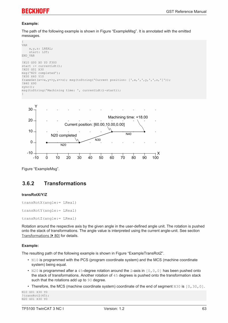
GST Reference Manual
TF5100 TwinCAT 3 NC I 63Version: 1.2
Example:
The path of the following example is shown in Figure “ExampleMsg”. It is annotated with the emittedmessages.{VAR x,y,z: LREAL; start: LDT;END_VAR
!N10 G00 X0 Y0 F300start := currentLdt();!N20 G01 X30msg('N20 completed');!N30 X60 Y10frameGet(x=>x,y=>y,z=>z); msg(toString('Current position: [',x,',',y,',',z,']'));!N40 X90sync();msg(toString('Machining time: ', currentLdt()-start));}
10 20 30 40 50
0
0
10
20
-10-10 60
X
Y
70 80 90 100
30
N20 completed
N20N30
N40
Current position: [60.00,10.00,0.00]
Machining time: +18.00
Figure “ExampleMsg”.
3.6.2 Transformations
transRotX/Y/Z
transRotX(angle:= LReal)
transRotY(angle:= LReal)
transRotZ(angle:= LReal)
Rotation around the respective axis by the given angle in the user-defined angle unit. The rotation is pushedonto the stack of transformations. The angle value is interpreted using the current angle-unit. See sectionTransformations [} 80] for details.
Example:
The resulting path of the following example is shown in Figure “ExampleTransRotZ”.
• N10 is programmed with the PCS (program coordinate system) and the MCS (machine coordinatesystem) being equal.
• N20 is programmed after a 45-degree rotation around the Z-axis in [0,0,0] has been pushed ontothe stack of transformations. Another rotation of 45 degrees is pushed onto the transformation stacksuch that the rotations add up to 90 degree.
• Therefore, the MCS (machine coordinate system) coordinate of the end of segment N30 is [0,30,0].N10 G01 X30 Y0!transRotZ(45);N20 G01 X30 Y0
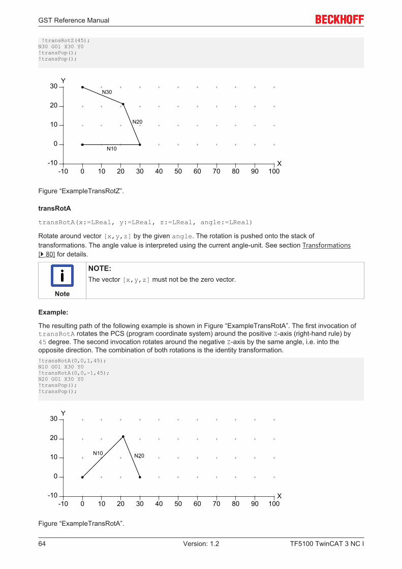
GST Reference Manual
TF5100 TwinCAT 3 NC I64 Version: 1.2
!transRotZ(45);N30 G01 X30 Y0!transPop();!transPop();
10 20 30 40 50
0
0
10
20
-10-10 60
X
Y
70 80 90 100
30
N10
N20
N30
Figure “ExampleTransRotZ”.
transRotA
transRotA(x:=LReal, y:=LReal, z:=LReal, angle:=LReal)
Rotate around vector [x,y,z] by the given angle. The rotation is pushed onto the stack oftransformations. The angle value is interpreted using the current angle-unit. See section Transformations[} 80] for details.
Note
NOTE:The vector [x,y,z] must not be the zero vector.
Example:
The resulting path of the following example is shown in Figure “ExampleTransRotA”. The first invocation oftransRotA rotates the PCS (program coordinate system) around the positive Z-axis (right-hand rule) by45 degree. The second invocation rotates around the negative Z-axis by the same angle, i.e. into theopposite direction. The combination of both rotations is the identity transformation.!transRotA(0,0,1,45);N10 G01 X30 Y0!transRotA(0,0,-1,45);N20 G01 X30 Y0!transPop();!transPop();
10 20 30 40 50
0
0
10
20
-10-10 60
X
Y
70 80 90 100
30
N20N10
Figure “ExampleTransRotA”.
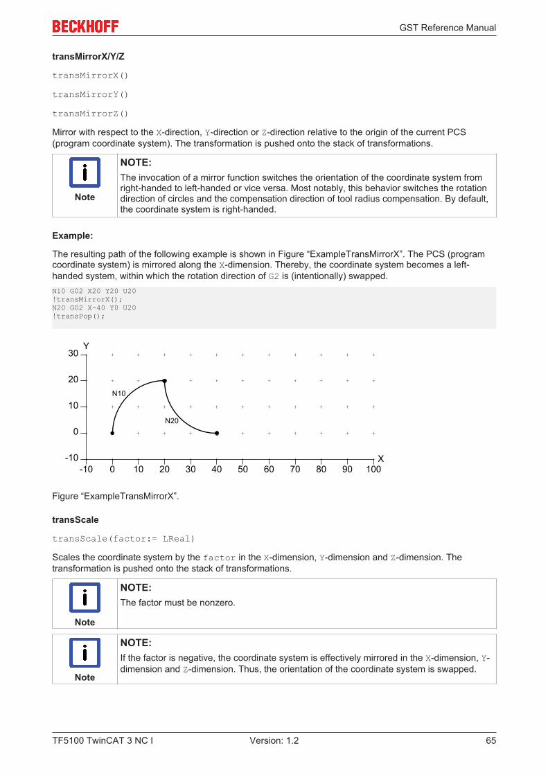
GST Reference Manual
TF5100 TwinCAT 3 NC I 65Version: 1.2
transMirrorX/Y/Z
transMirrorX()
transMirrorY()
transMirrorZ()
Mirror with respect to the X-direction, Y-direction or Z-direction relative to the origin of the current PCS(program coordinate system). The transformation is pushed onto the stack of transformations.
Note
NOTE:The invocation of a mirror function switches the orientation of the coordinate system fromright-handed to left-handed or vice versa. Most notably, this behavior switches the rotationdirection of circles and the compensation direction of tool radius compensation. By default,the coordinate system is right-handed.
Example:
The resulting path of the following example is shown in Figure “ExampleTransMirrorX”. The PCS (programcoordinate system) is mirrored along the X-dimension. Thereby, the coordinate system becomes a left-handed system, within which the rotation direction of G2 is (intentionally) swapped.N10 G02 X20 Y20 U20!transMirrorX();N20 G02 X-40 Y0 U20!transPop();
10 20 30 40 50
0
0
10
20
-10-10 60
X
Y
70 80 90 100
30
N20
N10
Figure “ExampleTransMirrorX”.
transScale
transScale(factor:= LReal)
Scales the coordinate system by the factor in the X-dimension, Y-dimension and Z-dimension. Thetransformation is pushed onto the stack of transformations.
Note
NOTE:The factor must be nonzero.
Note
NOTE:If the factor is negative, the coordinate system is effectively mirrored in the X-dimension, Y-dimension and Z-dimension. Thus, the orientation of the coordinate system is swapped.
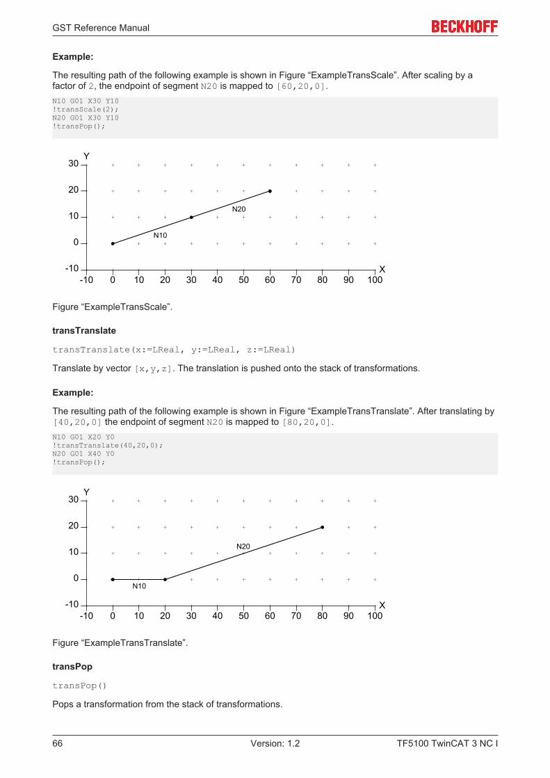
GST Reference Manual
TF5100 TwinCAT 3 NC I66 Version: 1.2
Example:
The resulting path of the following example is shown in Figure “ExampleTransScale”. After scaling by afactor of 2, the endpoint of segment N20 is mapped to [60,20,0].N10 G01 X30 Y10!transScale(2);N20 G01 X30 Y10!transPop();
10 20 30 40 50
0
0
10
20
-10-10 60
X
Y
70 80 90 100
30
N20
N10
Figure “ExampleTransScale”.
transTranslate
transTranslate(x:=LReal, y:=LReal, z:=LReal)
Translate by vector [x,y,z]. The translation is pushed onto the stack of transformations.
Example:
The resulting path of the following example is shown in Figure “ExampleTransTranslate”. After translating by[40,20,0] the endpoint of segment N20 is mapped to [80,20,0].N10 G01 X20 Y0!transTranslate(40,20,0);N20 G01 X40 Y0!transPop();
10 20 30 40 50
0
0
10
20
-10-10 60
X
Y
70 80 90 100
30
N20
N10
Figure “ExampleTransTranslate”.
transPop
transPop()
Pops a transformation from the stack of transformations.
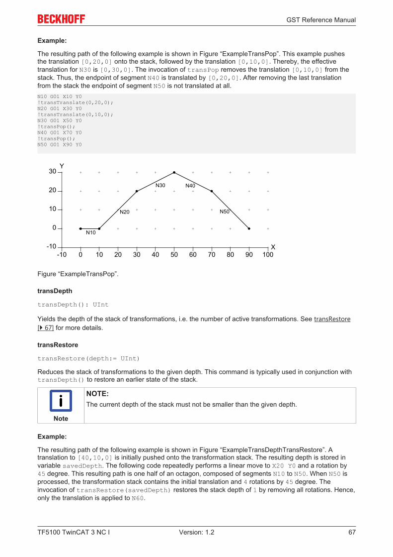
GST Reference Manual
TF5100 TwinCAT 3 NC I 67Version: 1.2
Example:
The resulting path of the following example is shown in Figure “ExampleTransPop”. This example pushesthe translation [0,20,0] onto the stack, followed by the translation [0,10,0]. Thereby, the effectivetranslation for N30 is [0,30,0]. The invocation of transPop removes the translation [0,10,0] from thestack. Thus, the endpoint of segment N40 is translated by [0,20,0]. After removing the last translationfrom the stack the endpoint of segment N50 is not translated at all.N10 G01 X10 Y0!transTranslate(0,20,0);N20 G01 X30 Y0!transTranslate(0,10,0);N30 G01 X50 Y0!transPop();N40 G01 X70 Y0!transPop();N50 G01 X90 Y0
10 20 30 40 50
0
0
10
20
-10-10 60
X
Y
70 80 90 100
30
N20
N10
N30 N40
N50
Figure “ExampleTransPop”.
transDepth
transDepth(): UInt
Yields the depth of the stack of transformations, i.e. the number of active transformations. See transRestore[} 67] for more details.
transRestore
transRestore(depth:= UInt)
Reduces the stack of transformations to the given depth. This command is typically used in conjunction withtransDepth() to restore an earlier state of the stack.
Note
NOTE:The current depth of the stack must not be smaller than the given depth.
Example:
The resulting path of the following example is shown in Figure “ExampleTransDepthTransRestore”. Atranslation to [40,10,0] is initially pushed onto the transformation stack. The resulting depth is stored invariable savedDepth. The following code repeatedly performs a linear move to X20 Y0 and a rotation by45 degree. This resulting path is one half of an octagon, composed of segments N10 to N50. When N50 isprocessed, the transformation stack contains the initial translation and 4 rotations by 45 degree. Theinvocation of transRestore(savedDepth) restores the stack depth of 1 by removing all rotations. Hence,only the translation is applied to N60.
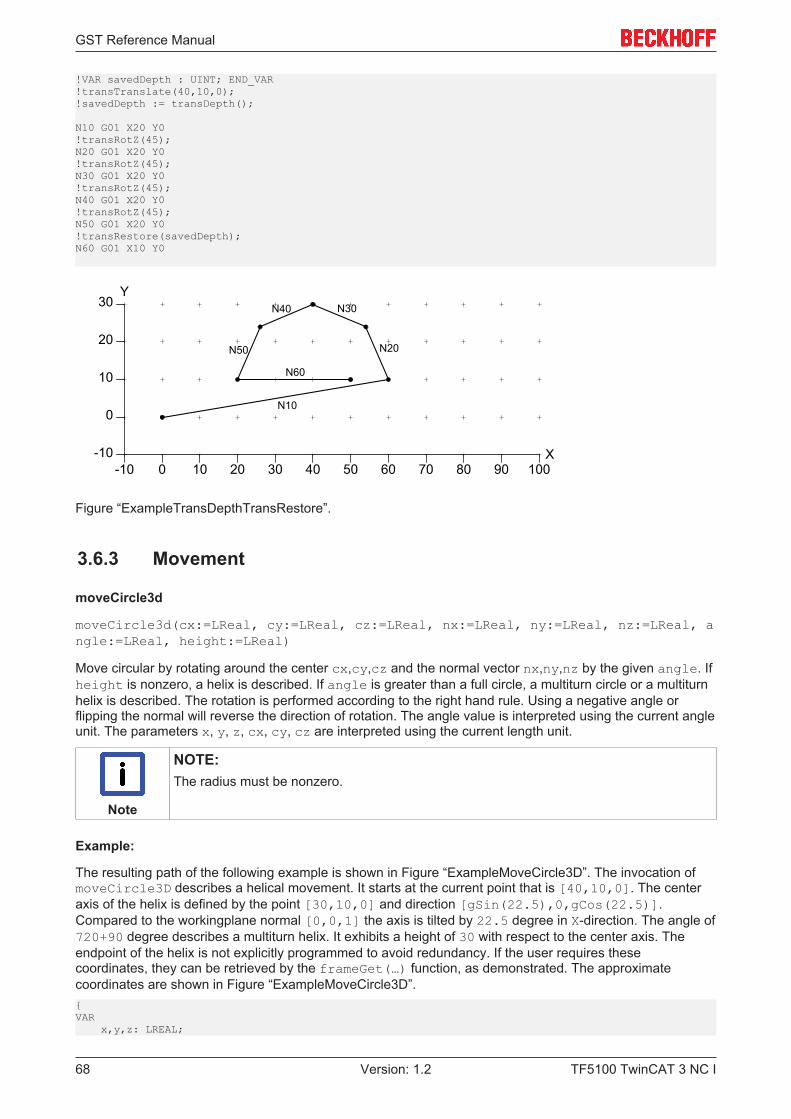
GST Reference Manual
TF5100 TwinCAT 3 NC I68 Version: 1.2
!VAR savedDepth : UINT; END_VAR!transTranslate(40,10,0);!savedDepth := transDepth();
N10 G01 X20 Y0!transRotZ(45);N20 G01 X20 Y0!transRotZ(45);N30 G01 X20 Y0!transRotZ(45);N40 G01 X20 Y0!transRotZ(45);N50 G01 X20 Y0!transRestore(savedDepth);N60 G01 X10 Y0
10 20 30 40 50
0
0
10
20
-10-10 60
X
Y
70 80 90 100
30
N10
N20
N30N40
N50
N60
Figure “ExampleTransDepthTransRestore”.
3.6.3 Movement
moveCircle3d
moveCircle3d(cx:=LReal, cy:=LReal, cz:=LReal, nx:=LReal, ny:=LReal, nz:=LReal, angle:=LReal, height:=LReal)
Move circular by rotating around the center cx,cy,cz and the normal vector nx,ny,nz by the given angle. Ifheight is nonzero, a helix is described. If angle is greater than a full circle, a multiturn circle or a multiturnhelix is described. The rotation is performed according to the right hand rule. Using a negative angle orflipping the normal will reverse the direction of rotation. The angle value is interpreted using the current angleunit. The parameters x, y, z, cx, cy, cz are interpreted using the current length unit.
Note
NOTE:The radius must be nonzero.
Example:
The resulting path of the following example is shown in Figure “ExampleMoveCircle3D”. The invocation ofmoveCircle3D describes a helical movement. It starts at the current point that is [40,10,0]. The centeraxis of the helix is defined by the point [30,10,0] and direction [gSin(22.5),0,gCos(22.5)].Compared to the workingplane normal [0,0,1] the axis is tilted by 22.5 degree in X-direction. The angle of720+90 degree describes a multiturn helix. It exhibits a height of 30 with respect to the center axis. Theendpoint of the helix is not explicitly programmed to avoid redundancy. If the user requires thesecoordinates, they can be retrieved by the frameGet(…) function, as demonstrated. The approximatecoordinates are shown in Figure “ExampleMoveCircle3D”.{VAR x,y,z: LREAL;
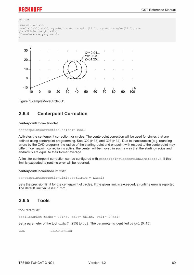
GST Reference Manual
TF5100 TwinCAT 3 NC I 69Version: 1.2
END_VAR
!N10 G01 X40 Y10moveCircle3D(cx:=30, cy:=10, cz:=0, nx:=gSin(22.5), ny:=0, nz:=gCos(22.5), an-gle:=720+90, height:=30);!frameGet(x=>x,y=>y,z=>z);}
10 20 30 40 50
0
0
10
20
-10-10 60
X
Y
70 80 90 100
30X=42.94...Y=19.23...Z=31.25...
Figure “ExampleMoveCircle3D”.
3.6.4 Centerpoint Correction
centerpointCorrectionSet
centerpointCorrectionSet(on:= bool)
Activates the centerpoint correction for circles. The centerpoint correction will be used for circles that aredefined using centerpoint programming. See G02 [} 35] and G03 [} 37]. Due to inaccuracies (e.g. roundingerrors by the CAD program), the radius of the starting-point and endpoint with respect to the centerpoint maydiffer. If centerpoint correction is active, the center will be moved in such a way that the starting-radius andendradius are equal to their former average.
A limit for centerpoint correction can be configured with centerpointCorrectionLimitSet(…). If thislimit is exceeded, a runtime error will be reported.
centerpointCorrectionLimitSet
centerpointCorrectionLimitSet(limit:= LReal)
Sets the precision limit for the centerpoint of circles. If the given limit is exceeded, a runtime error is reported.The default limit value is 0.1 mm.
3.6.5 Tools
toolParamSet
toolParamSet(tidx:= USInt, col:= USInt, val:= LReal)
Set a parameter of the tool tidx (1..255) to val. The parameter is identified by col (0..15).
COL DESCRIPTION
GST Reference Manual
TF5100 TwinCAT 3 NC I70 Version: 1.2
0 tool numberFor giving the tool a number.Written to the T-parameter in the cyclic channel interface.
1 tool type (10: drill, 20: miller)The drill is type 10.The miller is type 20.
2 lengthDescribes the length of e.g. the drill.
3
4 radius
5 length (added to the length value of column 2)Describes the wear on e.g. the drill. The wear has to be given as a negative value as itis added to the length.
6
7 radius (added to the radius value of column 4)
8 x-shiftCartesian tool displacement in x-direction.
9 y-shiftCartesian tool displacement in y-direction.
10 z-shiftCartesian tool displacement in z-direction.
toolParam
toolParam(tidx:= USInt, col:= USInt): LReal
Yields the given tool parameter.
toolSet
toolSet(index:= USInt, nr:= Int, tooltype:= ToolType, length:= LReal, radius:= LReal, lengthAdd:= LReal, radiusAdd:= LReal, offsetX:= LReal, offsetY:= LReal, offsetZ:= LReal)
Set all parameters of a tool. The index is used in D-words to refer to the tool. It must lie in the range 1 to 255.The parameter nr has only informational purpose. Typically, it is a company internal number to identify acertain tool. The parameter tooltype identifies the kind of tool, like a drill for instance. The remaining
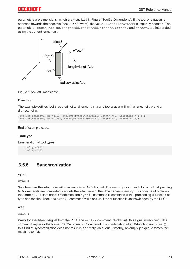
GST Reference Manual
TF5100 TwinCAT 3 NC I 71Version: 1.2
parameters are dimensions, which are visualized in Figure “ToolSetDimensions”. If the tool orientation ischanged towards the negative (see P [} 43]-word), the value length+lengthAdd is implicitly negated. Theparameters length, radius, lengthAdd, radiusAdd, offsetX, offsetY and offsetZ are interpretedusing the current length unit.
offsetXoffsetY
offsetZ
length+lengthAdd
radius+radiusAdd
X
Y
Z
Tool
Figure “ToolSetDimensions”.
Example:
The example defines tool 1 as a drill of total length 48.5 and tool 2 as a mill with a length of 30 and adiameter of 5.!toolSet(index:=1, nr:=4711, tooltype:=tooltypeDrill, length:=50, lengthAdd:=-1.5);!toolSet(index:=2, nr:=10783, tooltype:=tooltypeMill, length:=30, radius:=2.5);
End of example code.
ToolType
Enumeration of tool types. tooltypeDrill tooltypeMill
3.6.6 Synchronization
sync
sync()
Synchronizes the interpreter with the associated NC-channel. The sync()-command blocks until all pendingNC-commands are completed, i.e. until the job-queue of the NC-channel is empty. This command replacesthe former @714-command. Oftentimes, the sync()-command is combined with a preceeding M-function oftype handshake. Then, the sync()-command will block until the M-function is acknowledged by the PLC.
wait
wait()
Waits for a GoAhead-signal from the PLC. The wait()-command blocks until this signal is received. Thiscommand replaces the former @717-command. Compared to a combination of an M-function and sync(),this kind of synchronization does not result in an empty job queue. Notably, an empty job queue forces themachine to halt.
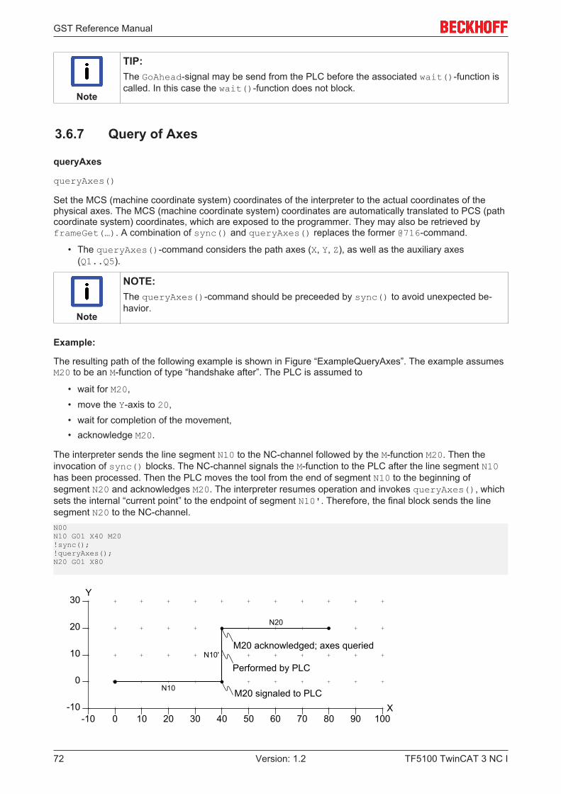
GST Reference Manual
TF5100 TwinCAT 3 NC I72 Version: 1.2
Note
TIP:The GoAhead-signal may be send from the PLC before the associated wait()-function iscalled. In this case the wait()-function does not block.
3.6.7 Query of Axes
queryAxes
queryAxes()
Set the MCS (machine coordinate system) coordinates of the interpreter to the actual coordinates of thephysical axes. The MCS (machine coordinate system) coordinates are automatically translated to PCS (pathcoordinate system) coordinates, which are exposed to the programmer. They may also be retrieved byframeGet(…). A combination of sync() and queryAxes() replaces the former @716-command.
• The queryAxes()-command considers the path axes (X, Y, Z), as well as the auxiliary axes(Q1..Q5).
Note
NOTE:The queryAxes()-command should be preceeded by sync() to avoid unexpected be-havior.
Example:
The resulting path of the following example is shown in Figure “ExampleQueryAxes”. The example assumesM20 to be an M-function of type “handshake after”. The PLC is assumed to
• wait for M20,• move the Y-axis to 20,• wait for completion of the movement,• acknowledge M20.
The interpreter sends the line segment N10 to the NC-channel followed by the M-function M20. Then theinvocation of sync() blocks. The NC-channel signals the M-function to the PLC after the line segment N10has been processed. Then the PLC moves the tool from the end of segment N10 to the beginning ofsegment N20 and acknowledges M20. The interpreter resumes operation and invokes queryAxes(), whichsets the internal “current point” to the endpoint of segment N10'. Therefore, the final block sends the linesegment N20 to the NC-channel.N00N10 G01 X40 M20!sync();!queryAxes();N20 G01 X80
10 20 30 40 50
0
0
10
20
-10-10 60
X
Y
70 80 90 100
30
N10
N10'
Performed by PLC
N20
M20 acknowledged; axes queried
M20 signaled to PLC
GST Reference Manual
TF5100 TwinCAT 3 NC I 73Version: 1.2
Figure “ExampleQueryAxes”.
3.6.8 Current Point
frameGet
frameGet(x:=LReal, y:=LReal, z:=LReal, a:=LReal, b:=LReal, c:=LReal)
Store the current frame of the PCS (program coordinate system) in x, y, z and a, b, c.
Example:
The output of the following example is shown below. The G-Code in the example performs a linearmovement to the PCS (program coordinate system) point [10,20,30]. Then these coordinates are storedin curX, curY, curZ by frameGet(…). The translation [1,2,3] that is pushed onto the transformation-stack leads to an adaption of the current PCS (program coordinate system) point such that the MCS(machine coordinate system) point [10,20,30] remains unchanged. Therefore, the subsequent call offrameGet(…) retrieves the PCS (program coordinate system) point [9,18,27].{VAR curX, curY, curZ : LREAL;END_VAR
!G01 X10 Y20 Z30 F65000
frameGet(x=>curX, y=>curY, z=>curZ);MSG(toString('test',curX,' ',curY,' ',curZ,''));
transTranslate(1,2,3);frameGet(x=>curX, y=>curY, z=>curZ);MSG(toString(curX,' ',curY,' ',curZ,''));}
Output:10.000000 20.000000 30.0000009.000000 18.000000 27.000000
qAxisGet
qAxisGet(q1:=LReal, q2:=LReal, q3:=LReal, q4:=LReal, q5:=LReal)
Store the current values of Q-axes in q1 to q5. The Q-axes are the auxiliary axes.
3.6.9 Tool Radius Compensation
trcApproachDepartSet
trcApproachDepartSet(approachRadius:= LReal, approachAngle:= LReal, departRadius:= LReal, departAngle:= LReal)
Configures the approach and depart behavior to use an arc of given radius and angle. If the product of radiusand angle are zero, no approach or depart segment will be inserted.
The resulting configuration is used by G41/G42.
trcOffsetSet
trcOffsetSet(offset:= LReal)
Configures the amount of segment extension that is used to close gaps. If offset is zero, no extension willbe performed.
GST Reference Manual
TF5100 TwinCAT 3 NC I74 Version: 1.2
The resulting configuration is used by G41/G42.
trcLimitSet
trcLimitSet(limit:= LReal)
Configures the lookahead that is used for collision elimination.
The resulting configuration is used by G41/G42.
trcParam
trcParam(): TrcParamType
Returns the current configuration as a structure value.
trcParamSet
trcParamSet(param:= TrcParamType)
Configures the tool radius compensation. This function is an alternative that summarizestrcApproachDepartSet, trcOffsetSet and trcLimitSet. It can be used in combination withtrcParam to load, save and restore different TRC (tool radius compensation) configurations efficiently.
TrcParamType
TrcParamType
This structure contains all configuration parameters of the tool radius compensation. It consists of thefollowing parameters.approachradius: LREAL;approachangle: LREAL;departRadius: LREAL;departAngle: LREAL;offset: LREAL;limit: LREAL;
See trcApproachDepartSet [} 73], trcOffsetSet [} 73], trcLimitSet [} 74] for a comprehensive description ofthe listed parameters.
collisionElimination
collisionElimination(nx:= LReal, ny:= LReal, nz:= LReal, limit:= ULInt)
Activates collision elimination with respect to the plane of the normal vector nx, ny, nz. Collisions within theprojection of the path onto the plane are eliminated. Supplying a zero vector deactivates collision elimination.The limit parameter can be used to restrict elimination to the last n segments. By default, elimination isunlimited.
collisionEliminationFlush
collisionEliminationFlush()
This function can be called during active collision elimination to ignore any conflicts between the pathpreceeding the call and the path succeeding the call.
3.6.10 Suppression of G-Code Blocks
disableMask
disableMask():= LWord
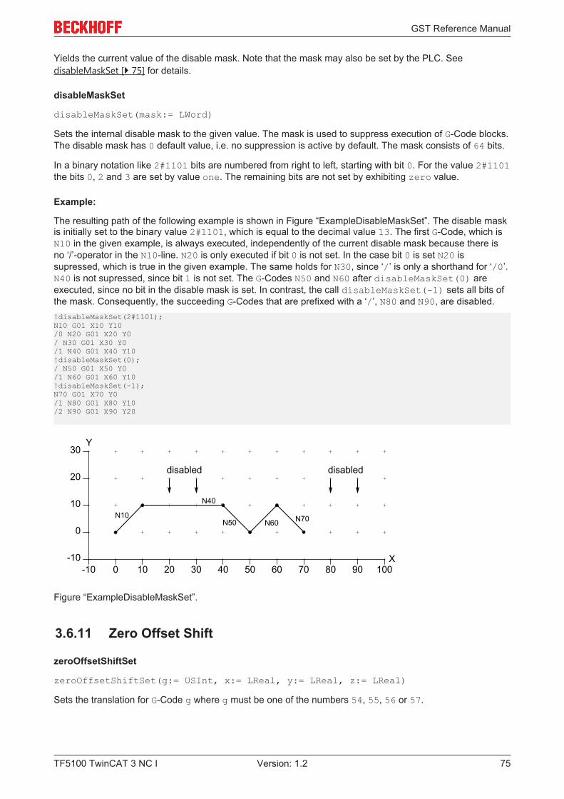
GST Reference Manual
TF5100 TwinCAT 3 NC I 75Version: 1.2
Yields the current value of the disable mask. Note that the mask may also be set by the PLC. SeedisableMaskSet [} 75] for details.
disableMaskSet
disableMaskSet(mask:= LWord)
Sets the internal disable mask to the given value. The mask is used to suppress execution of G-Code blocks.The disable mask has 0 default value, i.e. no suppression is active by default. The mask consists of 64 bits.
In a binary notation like 2#1101 bits are numbered from right to left, starting with bit 0. For the value 2#1101the bits 0, 2 and 3 are set by value one. The remaining bits are not set by exhibiting zero value.
Example:
The resulting path of the following example is shown in Figure “ExampleDisableMaskSet”. The disable maskis initially set to the binary value 2#1101, which is equal to the decimal value 13. The first G-Code, which isN10 in the given example, is always executed, independently of the current disable mask because there isno ‘/’-operator in the N10-line. N20 is only executed if bit 0 is not set. In the case bit 0 is set N20 issupressed, which is true in the given example. The same holds for N30, since ‘/’ is only a shorthand for ‘/0’.N40 is not supressed, since bit 1 is not set. The G-Codes N50 and N60 after disableMaskSet(0) areexecuted, since no bit in the disable mask is set. In contrast, the call disableMaskSet(-1) sets all bits ofthe mask. Consequently, the succeeding G-Codes that are prefixed with a ‘/’, N80 and N90, are disabled.!disableMaskSet(2#1101);N10 G01 X10 Y10/0 N20 G01 X20 Y0/ N30 G01 X30 Y0/1 N40 G01 X40 Y10!disableMaskSet(0);/ N50 G01 X50 Y0/1 N60 G01 X60 Y10!disableMaskSet(-1);N70 G01 X70 Y0/1 N80 G01 X80 Y10/2 N90 G01 X90 Y20
10 20 30 40 50
0
0
10
20
-10-10 60
X
Y
70 80 90 100
30
N10
N40
N50 N60 N70
disabled disabled
Figure “ExampleDisableMaskSet”.
3.6.11 Zero Offset Shift
zeroOffsetShiftSet
zeroOffsetShiftSet(g:= USInt, x:= LReal, y:= LReal, z:= LReal)
Sets the translation for G-Code g where g must be one of the numbers 54, 55, 56 or 57.

GST Reference Manual
TF5100 TwinCAT 3 NC I76 Version: 1.2
Example:
The resulting path of the following example is shown in Figure “ExampleZeroOffsetShiftSet”. The zero offsetshift of G54 is first set to the translation [0,10,0]. It gets active for N20 and any later segment endpointsuntil a novel translation is applied. The second invocation of zeroOffsetShiftSet has an immediateeffect. It applies to N30 and any later segment endpoints until a novel translation is applied. The same holdsfor the last invocation. However, the block N40 does not program the Y-coordinate. Therefore, the changedoes not become apparent for N40. (See section Transformations [} 80] for details.) Because the block N50programs the Y-coordinate, it applies the recent [0,30,0]-translation.!zeroOffsetShiftSet(g:=54, x:=0, y:=10, z:=0);N10 G01 X20 Y0N20 G01 X40 Y0 G54!zeroOffsetShiftSet(g:=54, x:=0, y:=20, z:=0);N30 G01 X60 Y0!zeroOffsetShiftSet(g:=54, x:=0, y:=30, z:=0);N40 G01 X80 N50 G01 X90 Y0
10 20 30 40 50
0
0
10
20
-10-10 60
X
Y
70 80 90 100
30
N10
N20 G54 G54 G54 G54
N30
N40
N50
Figure “ExampleZeroOffsetShiftSet”.
3.6.12 Units
unitAngleSet
unitAngleSet(unitAngle:= UnitAngle)
Set the unit for angles to unitAngle. The default is unitAngleDegree. The unit for angles applies to allNC-related functions like transRotX. It does not apply to ST-standard functions like sin. For this reasonthe interpreter offers a set of NC-specific counterparts like gSin that consider the angle unit.
UnitAngle
Enumeration of the following values:unitAngleRadian: 0…2piunitAngleDegree: 0…360unitAngleGon: 0…400unitAngleTurn: 0…1
.
unitLengthSet
unitLengthSet(unitLength:= UnitLength)
Set the unit for lengths to unitLength. The default is unitLengthMillimeter. The unit for lengthapplies to all NC-related functions like G01 or zeroOffsetShiftSet(…).
GST Reference Manual
TF5100 TwinCAT 3 NC I 77Version: 1.2
UnitLength
Enumeration of the following values:unitLengthMeterunitLengthCentimeterunitLengthMillimeterunitLengthMicrometerunitLengthNanometerunitLengthInchunitLengthFoot
.
unitTimeSet
unitTimeSet(unitTime:= UnitTime)
Set the unit for time to unitTime. The default is unitTimeSecond. The unit for time applies to all NC-related functions like G04. It does not apply to ST-standard functions like currentLdt().
UnitTime
Enumeration of the following values:unitTimeSecondunitTimeMillisecondunitTimeMicrosecondunitTimeMinuteunitTimeHour
.
unitVelocitySet
unitVelocitySet(unitLength:= UnitLength, unitTime:= UnitTime)
Set the unit for velocity to unitLength/unitTime. The default is unitLengthMillimeter/unitTimeMinute. The unit for velocity applies to all NC-related functions. It is used by the F-parameter forinstance.
3.6.13 Trigonometric (Unit Aware)
gSin
gSin(angle:= LReal)
Returns the sine of the given angle where the current angle unit is used to interpret the angle. (See sectionUnits [} 76] for details.) The return type is LReal. This function is not overloaded.
gCos
gCos(angle:= LReal)
Returns the cosine of the given angle where the current angle unit is used to interpret the angle. (Seesection Units [} 76] for details.) The return type is LReal. This function is not overloaded.
gTan
gTan(angle:= LReal)
Returns the tangent of the given angle where the current angle unit is used to interpret the angle. (Seesection Units [} 76] for details.) The return type is LReal. This function is not overloaded.
GST Reference Manual
TF5100 TwinCAT 3 NC I78 Version: 1.2
gASin
gASin(val:= LReal)
• Returns the arcsine of val in the current angle unit. (See section Units [} 76] for details.)• The return type is LReal. This function is not overloaded.• The result lies within the interval [-c/4,c/4] where c is the angle of a full circle in the current angle
unit.
Note
CONSTRAINT:The variable val must reside within the interval [-1,1].
gACos
gACos(val:= LReal)
• Returns the arccosine of val in the current angle unit. (See section Units [} 76] for details.)• The return type is LReal. This function is not overloaded.• The result lies within the interval [0,c/2] where c is the angle of a full circle in the current angle unit.
Note
CONSTRAINT:The variable val must reside within the interval [-1,1].
gATan
gATan(val:= LReal)
• Returns the arctangent of val in the current angle unit. (See section Units [} 76] for details.)• The return type is LReal. This function is not overloaded.• The result lies within the interval [-c/4,c/4] where c is the angle of a full circle in the current angle
unit.
gATan2
gATan2(y:= LReal, x:= LReal)
• Returns the arctangent of y/x in the current angle unit. (See section Units [} 76] for details.)• The return type is LReal. This function is not overloaded.• The result lies within the interval [-c/2,c/2] where c is the angle of a full circle in the current angle
unit.
3.6.14 Feed Mode
feedModeSet
feedModeSet(feedMode:= FeedModeType)
FeedModeType
Enumeration of the following values:fmContourfmInternalRadiusfmToolCenterPoint
GST Reference Manual
TF5100 TwinCAT 3 NC I 79Version: 1.2
.
3.6.15 Feed Interpolation
feedInterpolationSet
feedInterpolationSet(feedInterpolation:= FeedInterpolationType)
FeedInterpolationType
FeedInterpolationType
Enumeration of the following values:fiConstantfiLinear
.
3.6.16 Streaming of Large G-Code Files
runFile
runFile(path:= string)
The size of files that can be executed employing the GST-interpreter is limited. However, sometimes it isrequired to execute large files that may have been created e.g. by a CAD-program. Therefore, the user hasthe possibility to execute filestreams of native G-Code.
Executes the plain G-Code that is contained in the G-Code file given by path. The function call returns afterall lines in the supplied file have been processed. The function is intended for streaming large G-Code files tothe NC-kernel efficiently.
Note
Native G-Code: No Structured Text AllowedNote that the supplied G-Code file must not contain any ST-elements, but only plain G-Code.
A G-Code filestream from file 'myNativeGCodeFile.gcode' can be called from a GST-program lining upthe following syntax:!runfile('myNativeGCodeFile.gcode');
.
3.6.17 Vertex Smoothing
smoothingSet
smoothingSet(mainType:= SmoothingMainType, subType:= SmoothingSubType, value:= LReal)
Sets the vertex smoothing behavior according to the given parameters.
SmoothingMainType
Enumeration of the following values:
GST Reference Manual
TF5100 TwinCAT 3 NC I80 Version: 1.2
smoothingNonesmoothingParabolasmoothingBiquadraticsmoothingBezier3smoothingBezier5
.
SmoothingSubType
Enumeration of the following values:smoothingRadiussmoothingDistancesmoothingAdaptive
.
3.6.18 Dynamic Override
dynOverrideSet
dynOverrideSet(value:= LReal)
Set the dynamic override of axes to the given value. The factor must lie in the range 0 to 1.
3.6.19 Center Point Reference of Circles
circleCenterReferenceSet
circleCenterReferenceSet(value:= ReferenceType)
• Sets the center reference type for circles that are programmed by G02/G03 using a center point, whosedefinition involves the i,j,k-parameters.
• For referenceAbsolute the center point of the circle is defined by the supplied i,j,k-vector.• For referenceRelative the center point is defined by the sum of the circle starting-point and the
supplied i,j,k-vector. This is the default and usual behavior of G-Code.
ReferenceType
Enumeration of the following values:referenceAbsolutereferenceRelative
.
3.7 TransformationsThe relation between the MCS (machine coordinate system) and the PCS (program coordinate system) isdefined by the effective transformation T. T is the concatenation of the transformations TZ, TU andTT (T = TZ * TU * TT). Note that the order of concatenation is significant for the transformations do notcommute in general. The transformation TZ represents a (historical) zero offset shift, the transformation TUrepresents a user defined transformation and the transformation TT represents a tool transformation. Theyare described in detail later.
Figure “TransformationsTzTuTt” visualizes the relation between the MCS (machine coordinate system) andthe PCS (program coordinate system):
• TZ is defined to be a translation by [20,20,0],
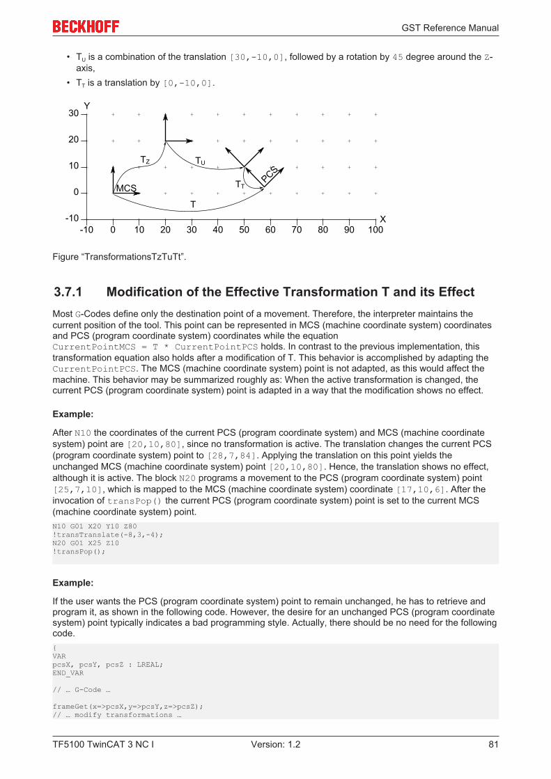
GST Reference Manual
TF5100 TwinCAT 3 NC I 81Version: 1.2
• TU is a combination of the translation [30,-10,0], followed by a rotation by 45 degree around the Z-axis,
• TT is a translation by [0,-10,0].
10 20 30 40 50
0
0
10
20
-10-10 60
X
Y
70 80 90 100
30
MCS
TZ TU
TT
T
PCS
Figure “TransformationsTzTuTt”.
3.7.1 Modification of the Effective Transformation T and its EffectMost G-Codes define only the destination point of a movement. Therefore, the interpreter maintains thecurrent position of the tool. This point can be represented in MCS (machine coordinate system) coordinatesand PCS (program coordinate system) coordinates while the equationCurrentPointMCS = T * CurrentPointPCS holds. In contrast to the previous implementation, thistransformation equation also holds after a modification of T. This behavior is accomplished by adapting theCurrentPointPCS. The MCS (machine coordinate system) point is not adapted, as this would affect themachine. This behavior may be summarized roughly as: When the active transformation is changed, thecurrent PCS (program coordinate system) point is adapted in a way that the modification shows no effect.
Example:
After N10 the coordinates of the current PCS (program coordinate system) and MCS (machine coordinatesystem) point are [20,10,80], since no transformation is active. The translation changes the current PCS(program coordinate system) point to [28,7,84]. Applying the translation on this point yields theunchanged MCS (machine coordinate system) point [20,10,80]. Hence, the translation shows no effect,although it is active. The block N20 programs a movement to the PCS (program coordinate system) point[25,7,10], which is mapped to the MCS (machine coordinate system) coordinate [17,10,6]. After theinvocation of transPop() the current PCS (program coordinate system) point is set to the current MCS(machine coordinate system) point.N10 G01 X20 Y10 Z80!transTranslate(-8,3,-4);N20 G01 X25 Z10!transPop();
Example:
If the user wants the PCS (program coordinate system) point to remain unchanged, he has to retrieve andprogram it, as shown in the following code. However, the desire for an unchanged PCS (program coordinatesystem) point typically indicates a bad programming style. Actually, there should be no need for the followingcode.{VARpcsX, pcsY, pcsZ : LREAL;END_VAR
// … G-Code …
frameGet(x=>pcsX,y=>pcsY,z=>pcsZ);// … modify transformations …
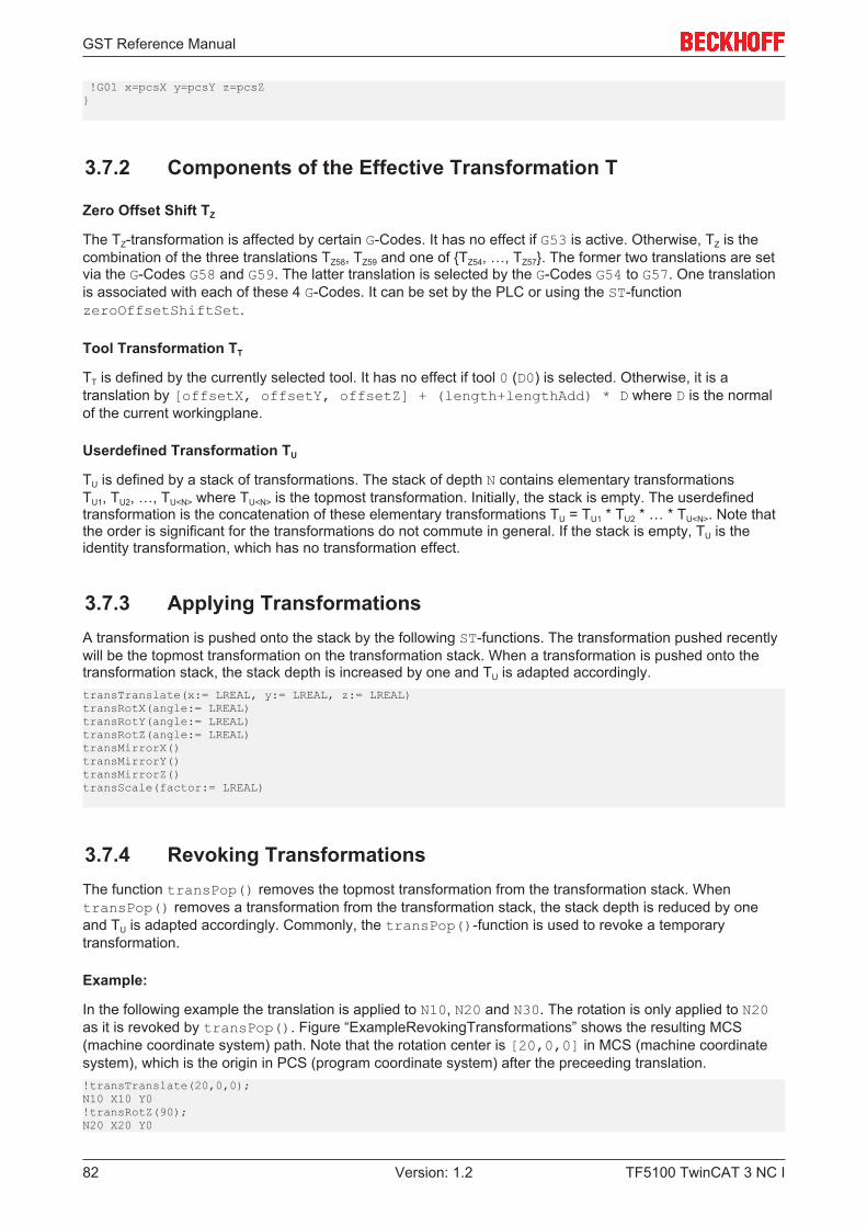
GST Reference Manual
TF5100 TwinCAT 3 NC I82 Version: 1.2
!G01 x=pcsX y=pcsY z=pcsZ}
3.7.2 Components of the Effective Transformation T
Zero Offset Shift TZ
The TZ-transformation is affected by certain G-Codes. It has no effect if G53 is active. Otherwise, TZ is thecombination of the three translations TZ58, TZ59 and one of {TZ54, …, TZ57}. The former two translations are setvia the G-Codes G58 and G59. The latter translation is selected by the G-Codes G54 to G57. One translationis associated with each of these 4 G-Codes. It can be set by the PLC or using the ST-functionzeroOffsetShiftSet.
Tool Transformation TT
TT is defined by the currently selected tool. It has no effect if tool 0 (D0) is selected. Otherwise, it is atranslation by [offsetX, offsetY, offsetZ] + (length+lengthAdd) * D where D is the normalof the current workingplane.
Userdefined Transformation TU
TU is defined by a stack of transformations. The stack of depth N contains elementary transformationsTU1, TU2, …, TU<N> where TU<N> is the topmost transformation. Initially, the stack is empty. The userdefinedtransformation is the concatenation of these elementary transformations TU = TU1 * TU2 * … * TU<N>. Note thatthe order is significant for the transformations do not commute in general. If the stack is empty, TU is theidentity transformation, which has no transformation effect.
3.7.3 Applying TransformationsA transformation is pushed onto the stack by the following ST-functions. The transformation pushed recentlywill be the topmost transformation on the transformation stack. When a transformation is pushed onto thetransformation stack, the stack depth is increased by one and TU is adapted accordingly.transTranslate(x:= LREAL, y:= LREAL, z:= LREAL)transRotX(angle:= LREAL)transRotY(angle:= LREAL)transRotZ(angle:= LREAL)transMirrorX()transMirrorY()transMirrorZ()transScale(factor:= LREAL)
3.7.4 Revoking TransformationsThe function transPop() removes the topmost transformation from the transformation stack. WhentransPop() removes a transformation from the transformation stack, the stack depth is reduced by oneand TU is adapted accordingly. Commonly, the transPop()-function is used to revoke a temporarytransformation.
Example:
In the following example the translation is applied to N10, N20 and N30. The rotation is only applied to N20as it is revoked by transPop(). Figure “ExampleRevokingTransformations” shows the resulting MCS(machine coordinate system) path. Note that the rotation center is [20,0,0] in MCS (machine coordinatesystem), which is the origin in PCS (program coordinate system) after the preceeding translation.!transTranslate(20,0,0);N10 X10 Y0!transRotZ(90);N20 X20 Y0
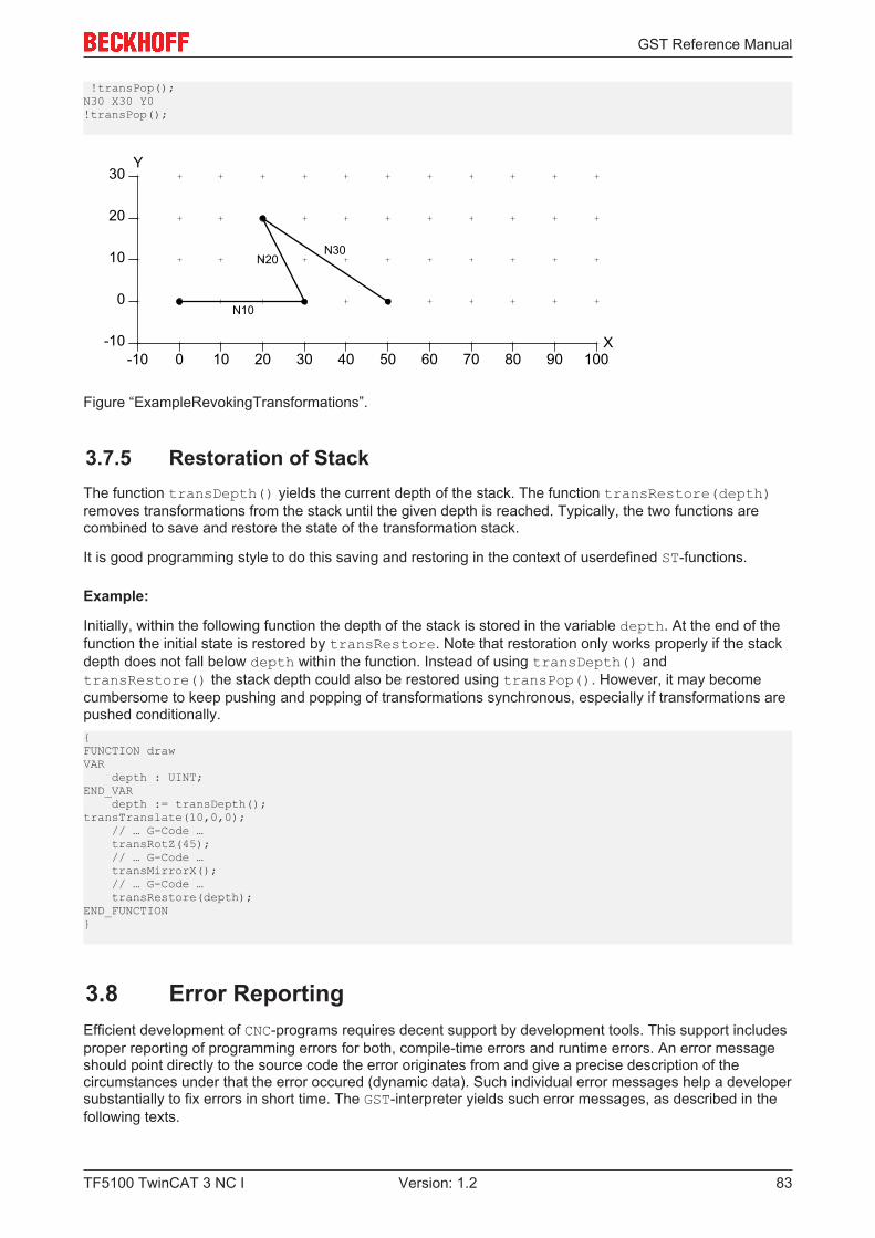
GST Reference Manual
TF5100 TwinCAT 3 NC I 83Version: 1.2
!transPop();N30 X30 Y0!transPop();
10 20 30 40 50
0
0
10
20
-10-10 60
X
Y
70 80 90 100
30
N10
N30N20
Figure “ExampleRevokingTransformations”.
3.7.5 Restoration of StackThe function transDepth() yields the current depth of the stack. The function transRestore(depth)removes transformations from the stack until the given depth is reached. Typically, the two functions arecombined to save and restore the state of the transformation stack.
It is good programming style to do this saving and restoring in the context of userdefined ST-functions.
Example:
Initially, within the following function the depth of the stack is stored in the variable depth. At the end of thefunction the initial state is restored by transRestore. Note that restoration only works properly if the stackdepth does not fall below depth within the function. Instead of using transDepth() andtransRestore() the stack depth could also be restored using transPop(). However, it may becomecumbersome to keep pushing and popping of transformations synchronous, especially if transformations arepushed conditionally.{FUNCTION drawVAR depth : UINT;END_VAR depth := transDepth();transTranslate(10,0,0); // … G-Code … transRotZ(45); // … G-Code … transMirrorX(); // … G-Code … transRestore(depth);END_FUNCTION}
3.8 Error ReportingEfficient development of CNC-programs requires decent support by development tools. This support includesproper reporting of programming errors for both, compile-time errors and runtime errors. An error messageshould point directly to the source code the error originates from and give a precise description of thecircumstances under that the error occured (dynamic data). Such individual error messages help a developersubstantially to fix errors in short time. The GST-interpreter yields such error messages, as described in thefollowing texts.
GST Reference Manual
TF5100 TwinCAT 3 NC I84 Version: 1.2
3.8.1 Error MessagesIn case of an error the interpreter produces a descriptive error message. An error message consists of asource code coordinate and a description. The source code coordinate links the error to its origin in the GST-program. It defines a range of source code stretching from the first character of the code range to the lastcharacter of the code range. Both, first and last character, are defined by their file, line and column. Note thatthe last character actually points to the first character behind the range, which is a common technicalconvention.
Example:
In the following example an integer variable i is declared and initialized. The initialization uses a floatingpointliteral. Since an implicit conversion from floatingpoint to integer is not allowed in ST, the interpreter producesthe descriptive error message given below when the program is loaded. The error message does not onlyreport that a type-error has occured, it also gives the precise position: File aaa.gst, line 3, column 14 to 17.This code range displays the literal ‘1.5’. In addition, the programmed type (real) and the expected type(int) are reported. With such a detailed error message bugs can be fixed by the developer easily.{VAR i : int := 1.5;END_VAR}
Error message:aaa.gst: 3.14-3.17: Invalid implicit conversion from type'<real literal>' to 'int'.
3.8.2 Compile-Time Errors and Runtime ErrorsErrors may occur during program loading (so called compile-time errors) or during program execution (socalled runtime errors). Fortunately, most errors are detected at compile-time. This detection includes missingfiles, syntax errors, type errors and unexpected identifiers. The developer gets feedback immediately whenhe tries to load the program. Thus, a part of unexpected failures during machining is avoided.
However, there are also errors that, by their nature, cannot be detected at compile-time. For instance, thiscircumstance includes a division by zero, since the divisor may be computed dynamically. If a runtime erroroccurs, the interpreter is stopped safely and an error message is produced. A runtime error message issimilar to a compile-time error message. It even includes a reference to the pertinent source code.
Example:
In the following example the FOR-loop contains a division of 10 by the loop variable i. Since the variable i isiterated from -3 to 3, this program leads to an error during the 4th iteration, when i has the value 0. Thiserror is detected at runtime and stops the interpreter. The error message shown below is reported. It pointsprecisely to the code ‘10/i’ in the example.
FILE aaa.gst:{VAR i, j : int;END_VAR
FOR i := -3 TO 3 DO j := j + 10/i;END_FOR;}
Error message:aaa.gst: 7.12-7.16: Division by zero
GST Reference Manual
TF5100 TwinCAT 3 NC I 85Version: 1.2
Example:
At runtime the interpreter also performs checking of array bounds. Consequently, invalid indices do not resultin unpredictable and typically fatal crashes. The runtime error message precisely defines location and originof the error at ‘idx’, reports the erroneously supplied index (20) and the valid index range (10..19).
FILE aaa.gst:{VAR idx : INT; a : ARRAY [10..19] OF INT;END_VAR
FOR idx := 10 TO 20 DO a[idx] := i;END_FOR;}
Error message:aaa.gst: 8.5-8.8: Out of bounds. 20 exceeds range 10..19.
3.8.3 Errors in G-CodeError reporting is also performed for G-Code. This reporting includes compile-time errors and runtime errors.Runtime error reporting includes invalid use of G-Code, e.g. like a bad definition for a circle.
Example:
In the following example the value of a string variable str is assigned to the address letter X of the G-Codeblock. As before the position of the error is precisely identified at ‘=str’ in the code. In addition, theprogrammed type and the expected type are reported.
FILE aaa.gst:{VAR str : string := 'Hello World';END_VAR}
G01 X=str F6000G01 Y100
Error message:7.5-7.9: Invalid implicit conversion from type 'string[255]'to 'lreal'
Example:
In the following example a sequence of circular arcs is processed by a FOR-loop. The radius of the arc is 4.The distance between the starting-point and endpoint of the arc is successively increased within eachiteration. During the 9th iteration the distance exceeds the circle diameter of 8. The reported error messageidentifies the origin G2 X=i*10+i U4 and gives information about the diameter and distance betweenstarting-point and endpoint.
FILE aaa.gst:{VAR i : INT;END_VAR
!G00 X0 Y0 Z0FOR i := 1 TO 10 DO !G01 X=i*10
GST Reference Manual
TF5100 TwinCAT 3 NC I86 Version: 1.2
!G02 X=i*10+i U4END_FOR;}
Error Message:aaa.gst: 9.4-10.1: Invalid definition of circle. Distancebetween start-point and end-point (=9.000000) is larger thandiameter (=8.000000).
3.8.4 PreprocessingDuring preprocessing #include-directives are replaced by the contents of the referenced files. Care hasbeen taken to maintain information about the origin of source code properly. Therefore, an error that iscaused by code in an included file will refer to that included file and not to the result of preprocessing, as asimple implementation would do.
Example:
In the following example the file aaa.gst includes the file bbb.gst. In the latter file the variables i and jare used in G-Codes. Variable i is declared at the beginning of aaa.gst, but j is not. Therefore, the errormessage below is issued. As you can see it references the use of variable j in file bbb.gst properly.
FILE aaa.gst:{VAR i : INT;END_VAR}
G00 X0 Y0 Z0
#include "bbb.gst"
G00 X100
FILE bbb.gst:G01 X=iG01 Y=jG01 Z100
Error message:bbb.gst: 2.6-2.7: Undeclared variable or enumeration value'j'
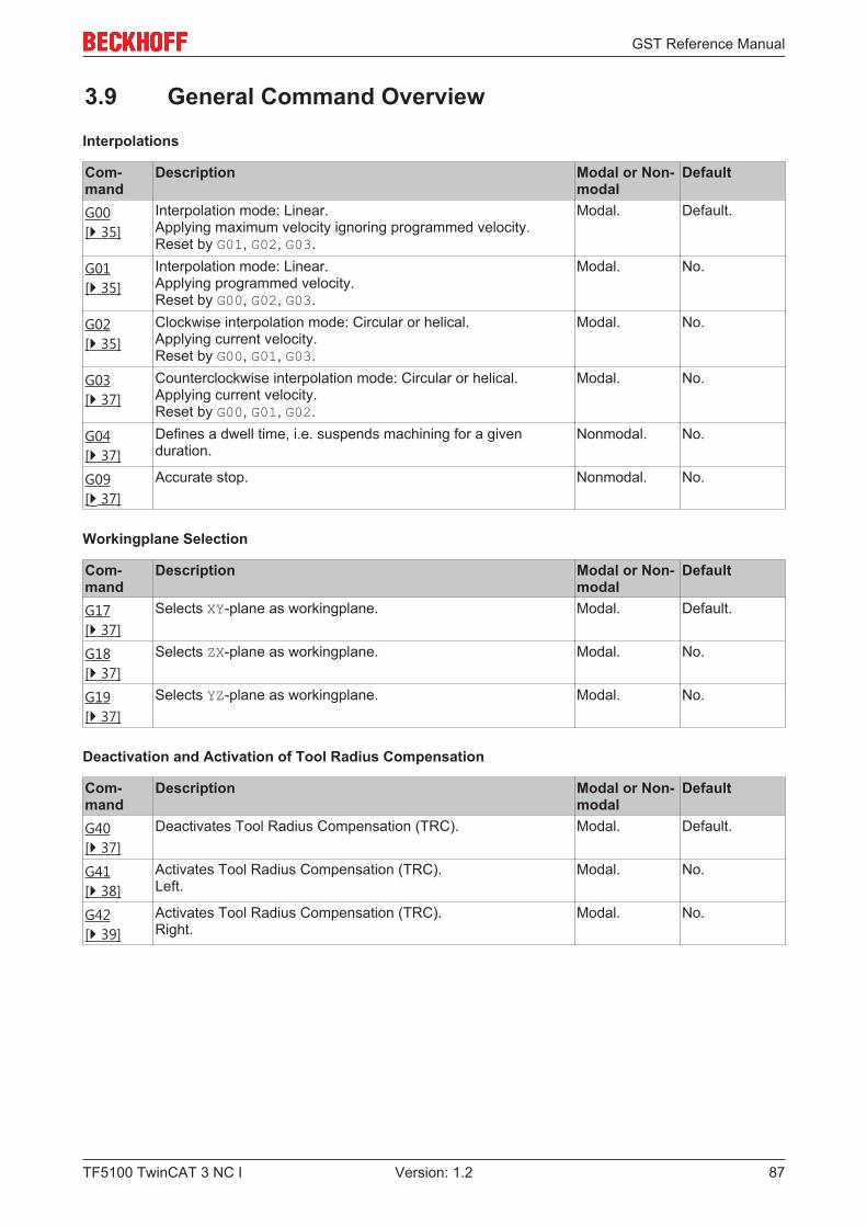
GST Reference Manual
TF5100 TwinCAT 3 NC I 87Version: 1.2
3.9 General Command Overview
Interpolations
Com-mand
Description Modal or Non-modal
Default
G00[} 35]
Interpolation mode: Linear.Applying maximum velocity ignoring programmed velocity.Reset by G01, G02, G03.
Modal. Default.
G01[} 35]
Interpolation mode: Linear.Applying programmed velocity.Reset by G00, G02, G03.
Modal. No.
G02[} 35]
Clockwise interpolation mode: Circular or helical.Applying current velocity.Reset by G00, G01, G03.
Modal. No.
G03[} 37]
Counterclockwise interpolation mode: Circular or helical.Applying current velocity.Reset by G00, G01, G02.
Modal. No.
G04[} 37]
Defines a dwell time, i.e. suspends machining for a givenduration.
Nonmodal. No.
G09[} 37]
Accurate stop. Nonmodal. No.
Workingplane Selection
Com-mand
Description Modal or Non-modal
Default
G17[} 37]
Selects XY-plane as workingplane. Modal. Default.
G18[} 37]
Selects ZX-plane as workingplane. Modal. No.
G19[} 37]
Selects YZ-plane as workingplane. Modal. No.
Deactivation and Activation of Tool Radius Compensation
Com-mand
Description Modal or Non-modal
Default
G40[} 37]
Deactivates Tool Radius Compensation (TRC). Modal. Default.
G41[} 38]
Activates Tool Radius Compensation (TRC).Left.
Modal. No.
G42[} 39]
Activates Tool Radius Compensation (TRC).Right.
Modal. No.
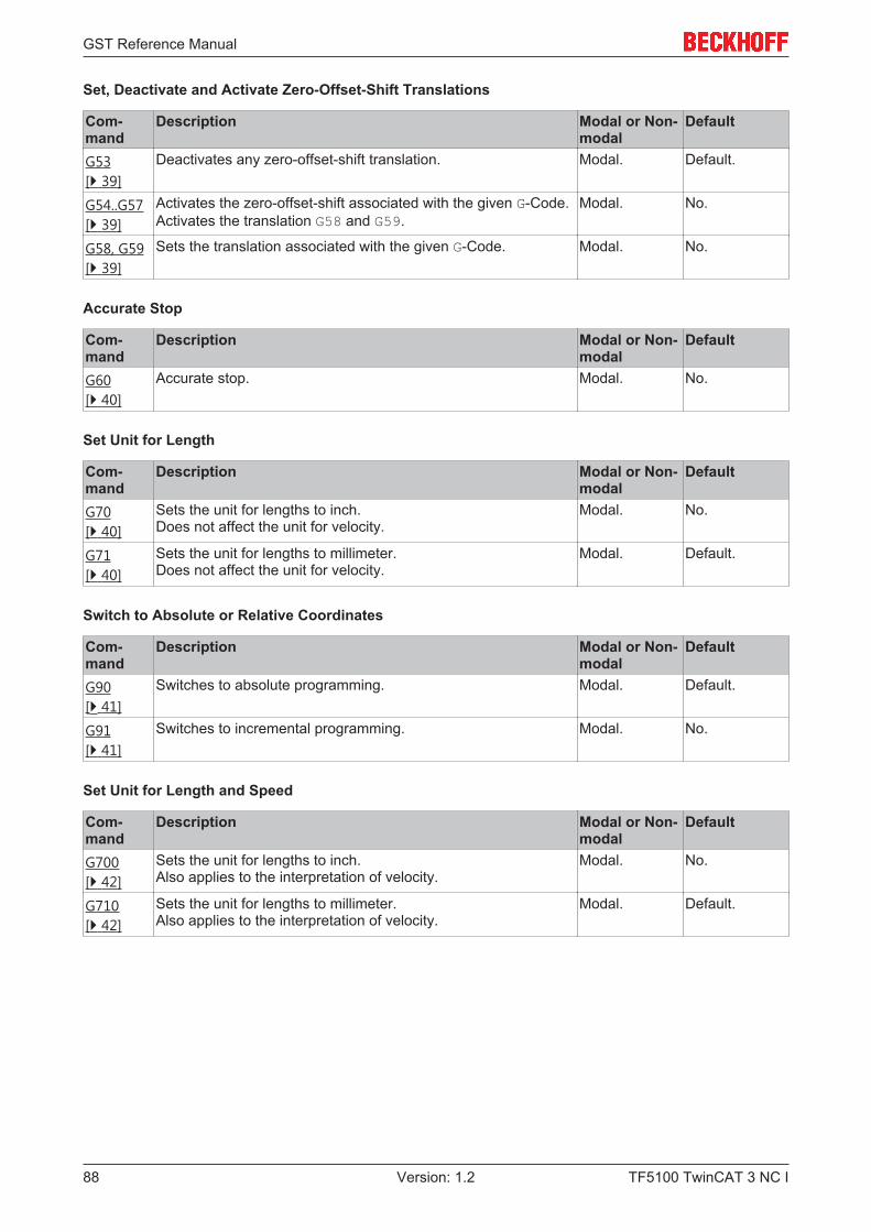
GST Reference Manual
TF5100 TwinCAT 3 NC I88 Version: 1.2
Set, Deactivate and Activate Zero-Offset-Shift Translations
Com-mand
Description Modal or Non-modal
Default
G53[} 39]
Deactivates any zero-offset-shift translation. Modal. Default.
G54..G57[} 39]
Activates the zero-offset-shift associated with the given G-Code.Activates the translation G58 and G59.
Modal. No.
G58, G59[} 39]
Sets the translation associated with the given G-Code. Modal. No.
Accurate Stop
Com-mand
Description Modal or Non-modal
Default
G60[} 40]
Accurate stop. Modal. No.
Set Unit for Length
Com-mand
Description Modal or Non-modal
Default
G70[} 40]
Sets the unit for lengths to inch.Does not affect the unit for velocity.
Modal. No.
G71[} 40]
Sets the unit for lengths to millimeter.Does not affect the unit for velocity.
Modal. Default.
Switch to Absolute or Relative Coordinates
Com-mand
Description Modal or Non-modal
Default
G90[} 41]
Switches to absolute programming. Modal. Default.
G91[} 41]
Switches to incremental programming. Modal. No.
Set Unit for Length and Speed
Com-mand
Description Modal or Non-modal
Default
G700[} 42]
Sets the unit for lengths to inch.Also applies to the interpretation of velocity.
Modal. No.
G710[} 42]
Sets the unit for lengths to millimeter.Also applies to the interpretation of velocity.
Modal. Default.
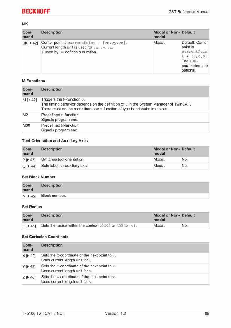
GST Reference Manual
TF5100 TwinCAT 3 NC I 89Version: 1.2
IJK
Com-mand
Description Modal or Non-modal
Default
IJK [} 42] Center point is currentPoint + [vx,vy,vz].Current length unit is used for vx,vy,vz.I used by G4 defines a duration.
Modal. Default: Centerpoint iscurrentPoint + [0,0,0].The IJK-parameters areoptional.
M-Functions
Com-mand
Description
M [} 42] Triggers the M-function v.The timing behavior depends on the definition of v in the System Manager of TwinCAT.There must not be more than one M-function of type handshake in a block.
M2 Predefined M-function.Signals program end.
M30 Predefined M-function.Signals program end.
Tool Orientation and Auxiliary Axes
Com-mand
Description Modal or Non-modal
Default
P [} 43] Switches tool orientation. Modal. No.
Q [} 44] Sets label for auxiliary axis. Modal. No.
Set Block Number
Com-mand
Description
N [} 45] Block number.
Set Radius
Com-mand
Description Modal or Non-modal
Default
U [} 45] Sets the radius within the context of G02 or G03 to |v|. Modal. No.
Set Cartesian Coordinate
Com-mand
Description
X [} 45] Sets the X-coordinate of the next point to v.Uses current length unit for v.
Y [} 45] Sets the Y-coordinate of the next point to v.Uses current length unit for v.
Z [} 46] Sets the Z-coordinate of the next point to v.Uses current length unit for v.
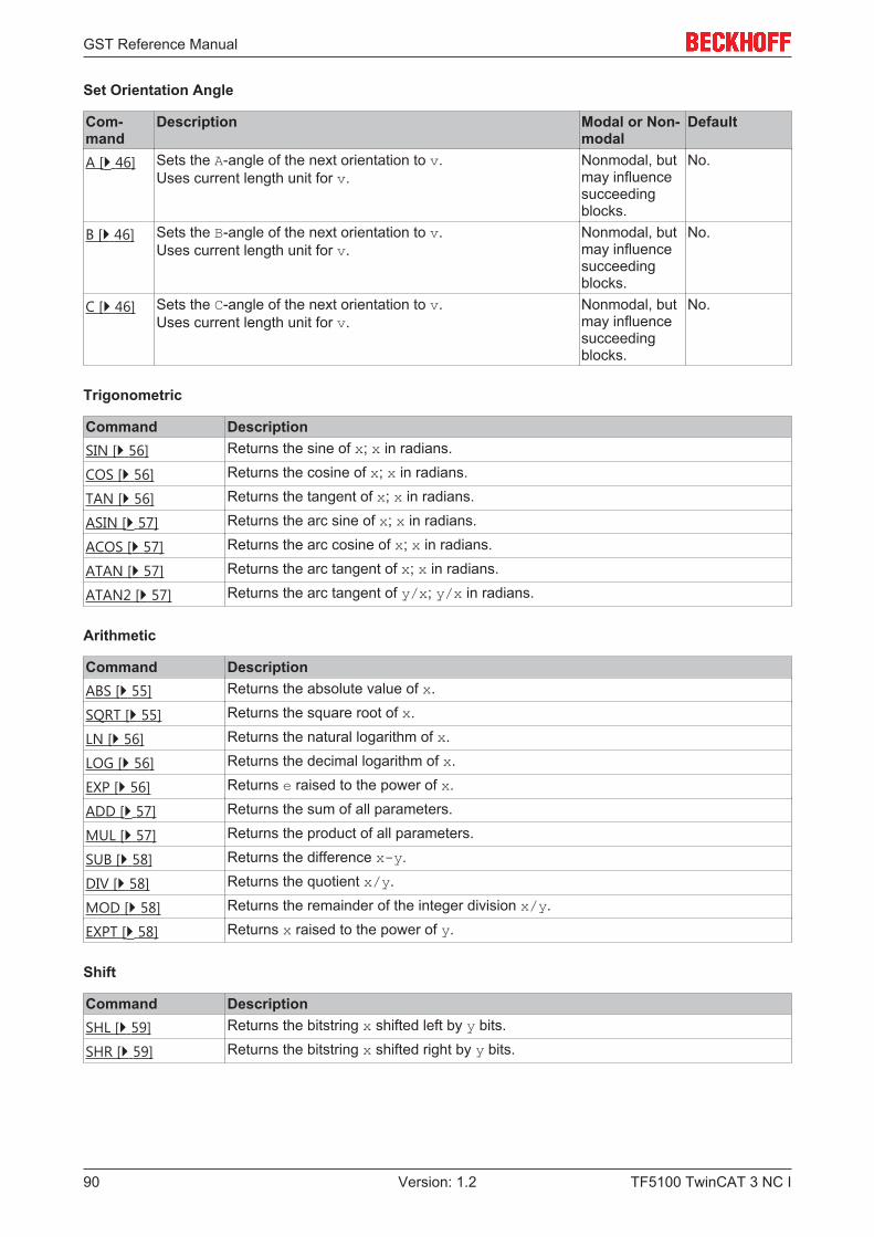
GST Reference Manual
TF5100 TwinCAT 3 NC I90 Version: 1.2
Set Orientation Angle
Com-mand
Description Modal or Non-modal
Default
A [} 46] Sets the A-angle of the next orientation to v.Uses current length unit for v.
Nonmodal, butmay influencesucceedingblocks.
No.
B [} 46] Sets the B-angle of the next orientation to v.Uses current length unit for v.
Nonmodal, butmay influencesucceedingblocks.
No.
C [} 46] Sets the C-angle of the next orientation to v.Uses current length unit for v.
Nonmodal, butmay influencesucceedingblocks.
No.
Trigonometric
Command DescriptionSIN [} 56] Returns the sine of x; x in radians.
COS [} 56] Returns the cosine of x; x in radians.
TAN [} 56] Returns the tangent of x; x in radians.
ASIN [} 57] Returns the arc sine of x; x in radians.
ACOS [} 57] Returns the arc cosine of x; x in radians.
ATAN [} 57] Returns the arc tangent of x; x in radians.
ATAN2 [} 57] Returns the arc tangent of y/x; y/x in radians.
Arithmetic
Command DescriptionABS [} 55] Returns the absolute value of x.
SQRT [} 55] Returns the square root of x.
LN [} 56] Returns the natural logarithm of x.
LOG [} 56] Returns the decimal logarithm of x.
EXP [} 56] Returns e raised to the power of x.
ADD [} 57] Returns the sum of all parameters.
MUL [} 57] Returns the product of all parameters.
SUB [} 58] Returns the difference x-y.
DIV [} 58] Returns the quotient x/y.
MOD [} 58] Returns the remainder of the integer division x/y.
EXPT [} 58] Returns x raised to the power of y.
Shift
Command DescriptionSHL [} 59] Returns the bitstring x shifted left by y bits.
SHR [} 59] Returns the bitstring x shifted right by y bits.
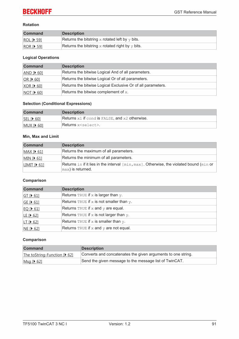
GST Reference Manual
TF5100 TwinCAT 3 NC I 91Version: 1.2
Rotation
Command DescriptionROL [} 59] Returns the bitstring x rotated left by y bits.
ROR [} 59] Returns the bitstring x rotated right by y bits.
Logical Operations
Command DescriptionAND [} 60] Returns the bitwise Logical And of all parameters.
OR [} 60] Returns the bitwise Logical Or of all parameters.
XOR [} 60] Returns the bitwise Logical Exclusive Or of all parameters.
NOT [} 60] Returns the bitwise complement of x.
Selection (Conditional Expressions)
Command DescriptionSEL [} 60] Returns x1 if cond is FALSE, and x2 otherwise.
MUX [} 60] Returns x<select>.
Min, Max and Limit
Command DescriptionMAX [} 61] Returns the maximum of all parameters.
MIN [} 61] Returns the minimum of all parameters.
LIMIT [} 61] Returns in if it lies in the interval [min,max]. Otherwise, the violated bound (min ormax) is returned.
Comparison
Command DescriptionGT [} 61] Returns TRUE if x is larger than y.
GE [} 61] Returns TRUE if x is not smaller than y.
EQ [} 61] Returns TRUE if x and y are equal.
LE [} 62] Returns TRUE if x is not larger than y.
LT [} 62] Returns TRUE if x is smaller than y.
NE [} 62] Returns TRUE if x and y are not equal.
Comparison
Command DescriptionThe toString-Function [} 62] Converts and concatenates the given arguments to one string.
Msg [} 62] Send the given message to the message list of TwinCAT.
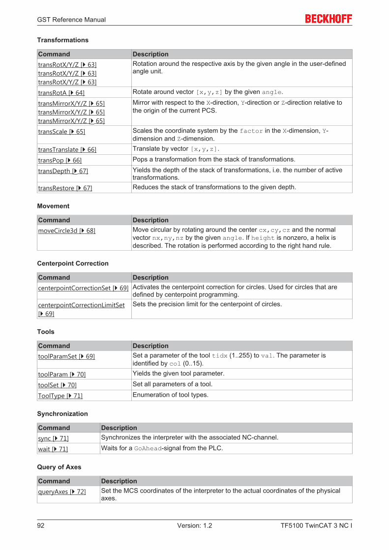
GST Reference Manual
TF5100 TwinCAT 3 NC I92 Version: 1.2
Transformations
Command DescriptiontransRotX/Y/Z [} 63]transRotX/Y/Z [} 63]transRotX/Y/Z [} 63]
Rotation around the respective axis by the given angle in the user-definedangle unit.
transRotA [} 64] Rotate around vector [x,y,z] by the given angle.
transMirrorX/Y/Z [} 65]transMirrorX/Y/Z [} 65]transMirrorX/Y/Z [} 65]
Mirror with respect to the X-direction, Y-direction or Z-direction relative tothe origin of the current PCS.
transScale [} 65] Scales the coordinate system by the factor in the X-dimension, Y-dimension and Z-dimension.
transTranslate [} 66] Translate by vector [x,y,z].
transPop [} 66] Pops a transformation from the stack of transformations.
transDepth [} 67] Yields the depth of the stack of transformations, i.e. the number of activetransformations.
transRestore [} 67] Reduces the stack of transformations to the given depth.
Movement
Command DescriptionmoveCircle3d [} 68] Move circular by rotating around the center cx,cy,cz and the normal
vector nx,ny,nz by the given angle. If height is nonzero, a helix isdescribed. The rotation is performed according to the right hand rule.
Centerpoint Correction
Command DescriptioncenterpointCorrectionSet [} 69] Activates the centerpoint correction for circles. Used for circles that are
defined by centerpoint programming.centerpointCorrectionLimitSet[} 69]
Sets the precision limit for the centerpoint of circles.
Tools
Command DescriptiontoolParamSet [} 69] Set a parameter of the tool tidx (1..255) to val. The parameter is
identified by col (0..15).
toolParam [} 70] Yields the given tool parameter.
toolSet [} 70] Set all parameters of a tool.
ToolType [} 71] Enumeration of tool types.
Synchronization
Command Descriptionsync [} 71] Synchronizes the interpreter with the associated NC-channel.
wait [} 71] Waits for a GoAhead-signal from the PLC.
Query of Axes
Command DescriptionqueryAxes [} 72] Set the MCS coordinates of the interpreter to the actual coordinates of the physical
axes.
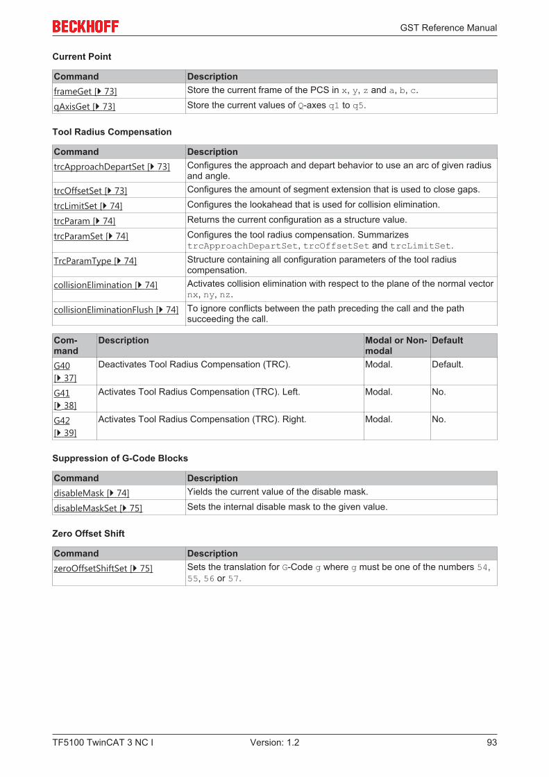
GST Reference Manual
TF5100 TwinCAT 3 NC I 93Version: 1.2
Current Point
Command DescriptionframeGet [} 73] Store the current frame of the PCS in x, y, z and a, b, c.
qAxisGet [} 73] Store the current values of Q-axes q1 to q5.
Tool Radius Compensation
Command DescriptiontrcApproachDepartSet [} 73] Configures the approach and depart behavior to use an arc of given radius
and angle.trcOffsetSet [} 73] Configures the amount of segment extension that is used to close gaps.
trcLimitSet [} 74] Configures the lookahead that is used for collision elimination.
trcParam [} 74] Returns the current configuration as a structure value.
trcParamSet [} 74] Configures the tool radius compensation. SummarizestrcApproachDepartSet, trcOffsetSet and trcLimitSet.
TrcParamType [} 74] Structure containing all configuration parameters of the tool radiuscompensation.
collisionElimination [} 74] Activates collision elimination with respect to the plane of the normal vectornx, ny, nz.
collisionEliminationFlush [} 74] To ignore conflicts between the path preceding the call and the pathsucceeding the call.
Com-mand
Description Modal or Non-modal
Default
G40[} 37]
Deactivates Tool Radius Compensation (TRC). Modal. Default.
G41[} 38]
Activates Tool Radius Compensation (TRC). Left. Modal. No.
G42[} 39]
Activates Tool Radius Compensation (TRC). Right. Modal. No.
Suppression of G-Code Blocks
Command DescriptiondisableMask [} 74] Yields the current value of the disable mask.
disableMaskSet [} 75] Sets the internal disable mask to the given value.
Zero Offset Shift
Command DescriptionzeroOffsetShiftSet [} 75] Sets the translation for G-Code g where g must be one of the numbers 54,
55, 56 or 57.
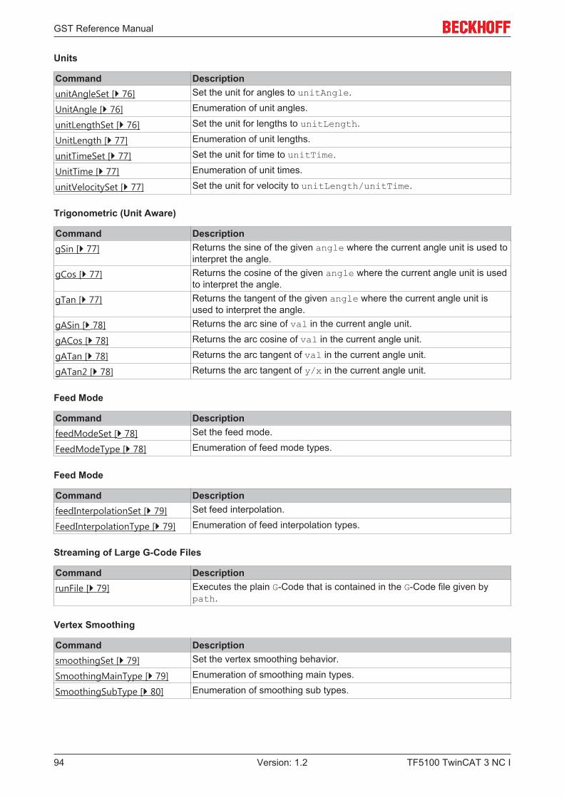
GST Reference Manual
TF5100 TwinCAT 3 NC I94 Version: 1.2
Units
Command DescriptionunitAngleSet [} 76] Set the unit for angles to unitAngle.
UnitAngle [} 76] Enumeration of unit angles.
unitLengthSet [} 76] Set the unit for lengths to unitLength.
UnitLength [} 77] Enumeration of unit lengths.
unitTimeSet [} 77] Set the unit for time to unitTime.
UnitTime [} 77] Enumeration of unit times.
unitVelocitySet [} 77] Set the unit for velocity to unitLength/unitTime.
Trigonometric (Unit Aware)
Command DescriptiongSin [} 77] Returns the sine of the given angle where the current angle unit is used to
interpret the angle.gCos [} 77] Returns the cosine of the given angle where the current angle unit is used
to interpret the angle.gTan [} 77] Returns the tangent of the given angle where the current angle unit is
used to interpret the angle.gASin [} 78] Returns the arc sine of val in the current angle unit.
gACos [} 78] Returns the arc cosine of val in the current angle unit.
gATan [} 78] Returns the arc tangent of val in the current angle unit.
gATan2 [} 78] Returns the arc tangent of y/x in the current angle unit.
Feed Mode
Command DescriptionfeedModeSet [} 78] Set the feed mode.
FeedModeType [} 78] Enumeration of feed mode types.
Feed Mode
Command DescriptionfeedInterpolationSet [} 79] Set feed interpolation.
FeedInterpolationType [} 79] Enumeration of feed interpolation types.
Streaming of Large G-Code Files
Command DescriptionrunFile [} 79] Executes the plain G-Code that is contained in the G-Code file given by
path.
Vertex Smoothing
Command DescriptionsmoothingSet [} 79] Set the vertex smoothing behavior.
SmoothingMainType [} 79] Enumeration of smoothing main types.
SmoothingSubType [} 80] Enumeration of smoothing sub types.
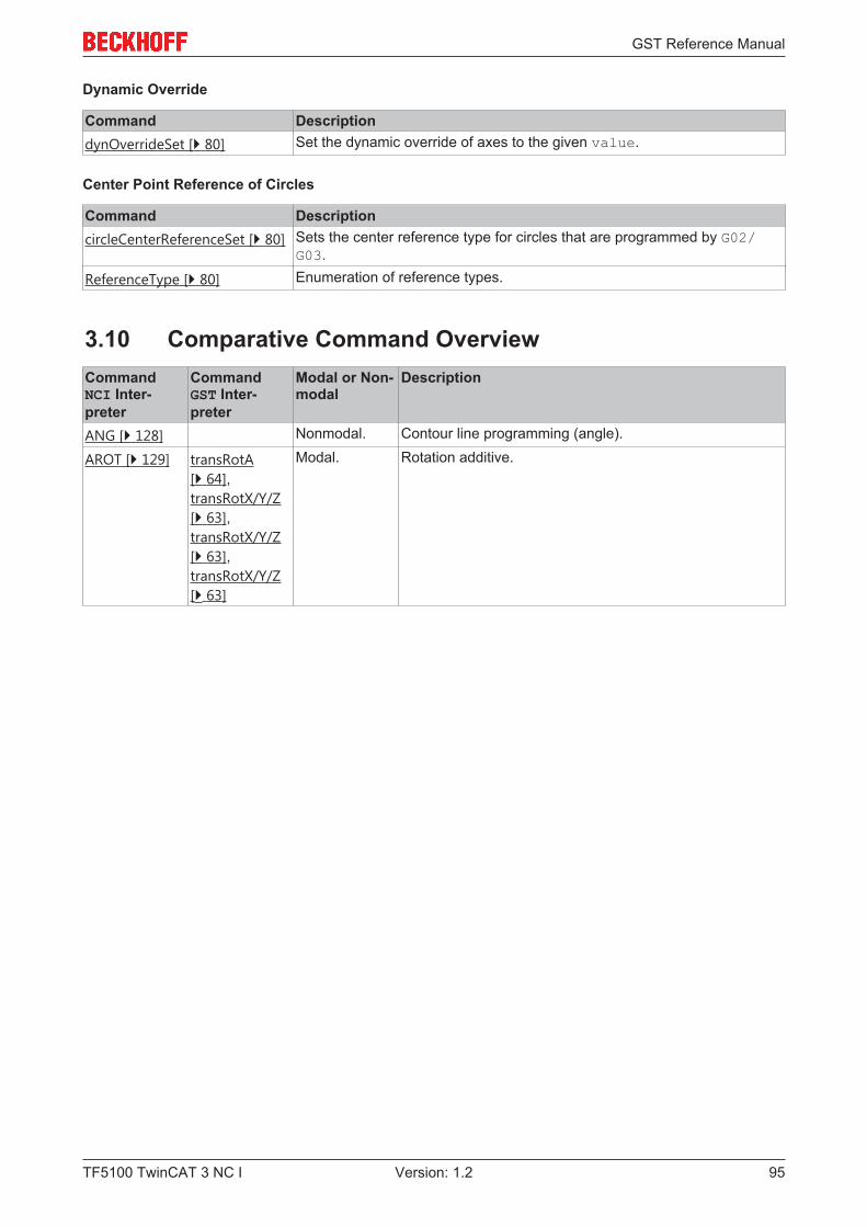
GST Reference Manual
TF5100 TwinCAT 3 NC I 95Version: 1.2
Dynamic Override
Command DescriptiondynOverrideSet [} 80] Set the dynamic override of axes to the given value.
Center Point Reference of Circles
Command DescriptioncircleCenterReferenceSet [} 80] Sets the center reference type for circles that are programmed by G02/
G03.
ReferenceType [} 80] Enumeration of reference types.
3.10 Comparative Command OverviewCommandNCI Inter-preter
CommandGST Inter-preter
Modal or Non-modal
Description
ANG [} 128] Nonmodal. Contour line programming (angle).
AROT [} 129] transRotA[} 64],transRotX/Y/Z[} 63],transRotX/Y/Z[} 63],transRotX/Y/Z[} 63]
Modal. Rotation additive.
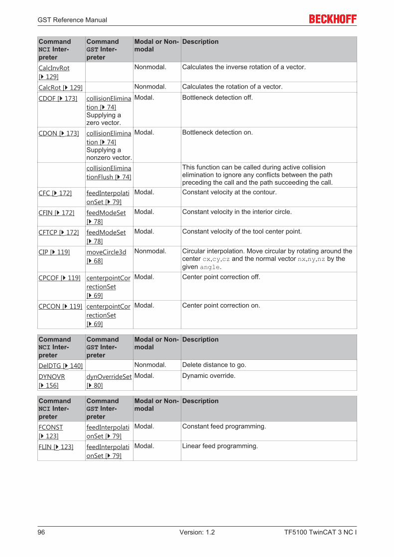
GST Reference Manual
TF5100 TwinCAT 3 NC I96 Version: 1.2
CommandNCI Inter-preter
CommandGST Inter-preter
Modal or Non-modal
Description
CalcInvRot[} 129]
Nonmodal. Calculates the inverse rotation of a vector.
CalcRot [} 129] Nonmodal. Calculates the rotation of a vector.
CDOF [} 173] collisionElimination [} 74]Supplying azero vector.
Modal. Bottleneck detection off.
CDON [} 173] collisionElimination [} 74]Supplying anonzero vector.
Modal. Bottleneck detection on.
collisionEliminationFlush [} 74]
This function can be called during active collisionelimination to ignore any conflicts between the pathpreceding the call and the path succeeding the call.
CFC [} 172] feedInterpolationSet [} 79]
Modal. Constant velocity at the contour.
CFIN [} 172] feedModeSet[} 78]
Modal. Constant velocity in the interior circle.
CFTCP [} 172] feedModeSet[} 78]
Modal. Constant velocity of the tool center point.
CIP [} 119] moveCircle3d[} 68]
Nonmodal. Circular interpolation. Move circular by rotating around thecenter cx,cy,cz and the normal vector nx,ny,nz by thegiven angle.
CPCOF [} 119] centerpointCorrectionSet[} 69]
Modal. Center point correction off.
CPCON [} 119] centerpointCorrectionSet[} 69]
Modal. Center point correction on.
CommandNCI Inter-preter
CommandGST Inter-preter
Modal or Non-modal
Description
DelDTG [} 140] Nonmodal. Delete distance to go.
DYNOVR[} 156]
dynOverrideSet[} 80]
Modal. Dynamic override.
CommandNCI Inter-preter
CommandGST Inter-preter
Modal or Non-modal
Description
FCONST[} 123]
feedInterpolationSet [} 79]
Modal. Constant feed programming.
FLIN [} 123] feedInterpolationSet [} 79]
Modal. Linear feed programming.
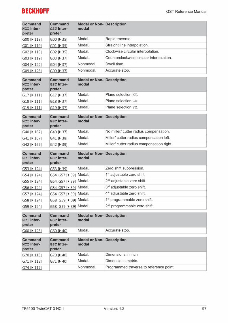
GST Reference Manual
TF5100 TwinCAT 3 NC I 97Version: 1.2
CommandNCI Inter-preter
CommandGST Inter-preter
Modal or Non-modal
Description
G00 [} 118] G00 [} 35] Modal. Rapid traverse.
G01 [} 119] G01 [} 35] Modal. Straight line interpolation.
G02 [} 119] G02 [} 35] Modal. Clockwise circular interpolation.
G03 [} 119] G03 [} 37] Modal. Counterclockwise circular interpolation.
G04 [} 122] G04 [} 37] Nonmodal. Dwell time.
G09 [} 123] G09 [} 37] Nonmodal. Accurate stop.
CommandNCI Inter-preter
CommandGST Inter-preter
Modal or Non-modal
Description
G17 [} 111] G17 [} 37] Modal. Plane selection XY.
G18 [} 111] G18 [} 37] Modal. Plane selection ZX.
G19 [} 111] G19 [} 37] Modal. Plane selection YZ.
CommandNCI Inter-preter
CommandGST Inter-preter
Modal or Non-modal
Description
G40 [} 167] G40 [} 37] Modal. No miller/ cutter radius compensation.
G41 [} 167] G41 [} 38] Modal. Miller/ cutter radius compensation left.
G42 [} 167] G42 [} 39] Modal. Miller/ cutter radius compensation right.
CommandNCI Inter-preter
CommandGST Inter-preter
Modal or Non-modal
Description
G53 [} 124] G53 [} 39] Modal. Zero shift suppression.
G54 [} 124] G54..G57 [} 39] Modal. 1st adjustable zero shift.
G55 [} 124] G54..G57 [} 39] Modal. 2nd adjustable zero shift.
G56 [} 124] G54..G57 [} 39] Modal. 3rd adjustable zero shift.
G57 [} 124] G54..G57 [} 39] Modal. 4th adjustable zero shift.
G58 [} 124] G58, G59 [} 39] Modal. 1st programmable zero shift.
G59 [} 124] G58, G59 [} 39] Modal. 2nd programmable zero shift.
CommandNCI Inter-preter
CommandGST Inter-preter
Modal or Non-modal
Description
G60 [} 123] G60 [} 40] Modal. Accurate stop.
CommandNCI Inter-preter
CommandGST Inter-preter
Modal or Non-modal
Description
G70 [} 113] G70 [} 40] Modal. Dimensions in inch.
G71 [} 113] G71 [} 40] Modal. Dimensions metric.
G74 [} 117] Nonmodal. Programmed traverse to reference point.
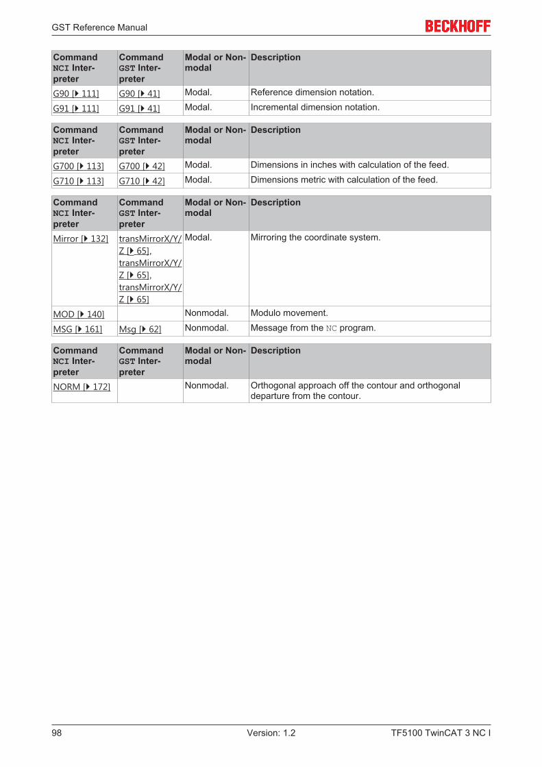
GST Reference Manual
TF5100 TwinCAT 3 NC I98 Version: 1.2
CommandNCI Inter-preter
CommandGST Inter-preter
Modal or Non-modal
Description
G90 [} 111] G90 [} 41] Modal. Reference dimension notation.
G91 [} 111] G91 [} 41] Modal. Incremental dimension notation.
CommandNCI Inter-preter
CommandGST Inter-preter
Modal or Non-modal
Description
G700 [} 113] G700 [} 42] Modal. Dimensions in inches with calculation of the feed.
G710 [} 113] G710 [} 42] Modal. Dimensions metric with calculation of the feed.
CommandNCI Inter-preter
CommandGST Inter-preter
Modal or Non-modal
Description
Mirror [} 132] transMirrorX/Y/Z [} 65],transMirrorX/Y/Z [} 65],transMirrorX/Y/Z [} 65]
Modal. Mirroring the coordinate system.
MOD [} 140] Nonmodal. Modulo movement.
MSG [} 161] Msg [} 62] Nonmodal. Message from the NC program.
CommandNCI Inter-preter
CommandGST Inter-preter
Modal or Non-modal
Description
NORM [} 172] Nonmodal. Orthogonal approach off the contour and orthogonaldeparture from the contour.

GST Reference Manual
TF5100 TwinCAT 3 NC I 99Version: 1.2
CommandNCI Inter-preter
CommandGST Inter-preter
Modal or Non-modal
Description
P+ [} 111] P [} 43] Modal. Feed direction positive.
P- [} 111] P [} 43] Modal. Feed direction negative.
paramAutoAccurateStop[} 139]
Modal. Automatic accurate stop.
paramAxisDynamics [} 156]
Modal. Parameterization of the axis dynamics.
paramC1ReductionFactor[} 158]
Modal. C1 reduction factor.
paramC2ReductionFactor[} 158]
Modal. C2 reduction factor.
paramCircularSmoothing[} 138]
Modal. Circular smoothing.
paramDevAngle [} 158]
Modal. C0 reduction - deflection angle.
paramGroupVertex [} 138]
Modal. Circular smoothing (old).
paramGroupDynamic [} 156]
Modal. Pathway dynamics (old).
paramPathDynamics [} 156]
Modal. Pathway dynamics.
Circularaccuracy[} 120]
Modal. Circular accuracy.
paramSplineSmoothing [} 136]
smoothingSet[} 79]
Modal. Vertex smoothing. NC: Smoothing with Bezier Splines.
paramVertexSmoothing[} 133]
smoothingSet[} 79]
Modal. Smoothing of segment transitions.
paramVeloJump [} 158]
Modal. C0 reduction - maximum step change in velocity.
paramVeloMin[} 159]
Modal. Minimum velocity.
paramZeroShift[} 124]
zeroOffsetShiftSet [} 75]
Modal. Parameterization of the configurable zero shift.
PathAxesPos[} 160]
frameGet[} 73],qAxisGet [} 73]
Nonmodal. Reads the actual position.
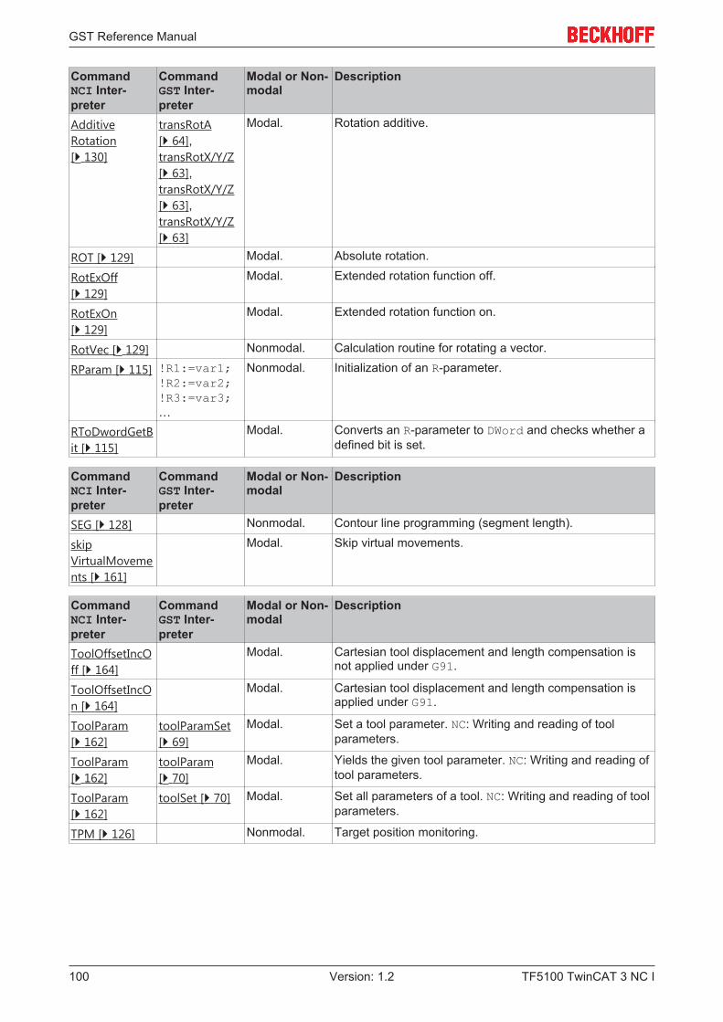
GST Reference Manual
TF5100 TwinCAT 3 NC I100 Version: 1.2
CommandNCI Inter-preter
CommandGST Inter-preter
Modal or Non-modal
Description
AdditiveRotation[} 130]
transRotA[} 64],transRotX/Y/Z[} 63],transRotX/Y/Z[} 63],transRotX/Y/Z[} 63]
Modal. Rotation additive.
ROT [} 129] Modal. Absolute rotation.
RotExOff[} 129]
Modal. Extended rotation function off.
RotExOn[} 129]
Modal. Extended rotation function on.
RotVec [} 129] Nonmodal. Calculation routine for rotating a vector.
RParam [} 115] !R1:=var1;!R2:=var2;!R3:=var3;…
Nonmodal. Initialization of an R-parameter.
RToDwordGetBit [} 115]
Modal. Converts an R-parameter to DWord and checks whether adefined bit is set.
CommandNCI Inter-preter
CommandGST Inter-preter
Modal or Non-modal
Description
SEG [} 128] Nonmodal. Contour line programming (segment length).
skipVirtualMovements [} 161]
Modal. Skip virtual movements.
CommandNCI Inter-preter
CommandGST Inter-preter
Modal or Non-modal
Description
ToolOffsetIncOff [} 164]
Modal. Cartesian tool displacement and length compensation isnot applied under G91.
ToolOffsetIncOn [} 164]
Modal. Cartesian tool displacement and length compensation isapplied under G91.
ToolParam[} 162]
toolParamSet[} 69]
Modal. Set a tool parameter. NC: Writing and reading of toolparameters.
ToolParam[} 162]
toolParam[} 70]
Modal. Yields the given tool parameter. NC: Writing and reading oftool parameters.
ToolParam[} 162]
toolSet [} 70] Modal. Set all parameters of a tool. NC: Writing and reading of toolparameters.
TPM [} 126] Nonmodal. Target position monitoring.
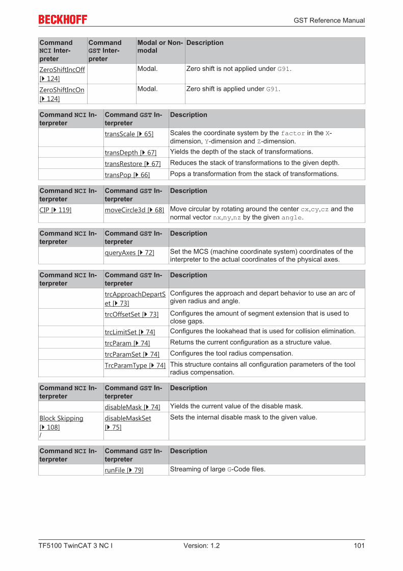
GST Reference Manual
TF5100 TwinCAT 3 NC I 101Version: 1.2
CommandNCI Inter-preter
CommandGST Inter-preter
Modal or Non-modal
Description
ZeroShiftIncOff[} 124]
Modal. Zero shift is not applied under G91.
ZeroShiftIncOn[} 124]
Modal. Zero shift is applied under G91.
Command NCI In-terpreter
Command GST In-terpreter
Description
transScale [} 65] Scales the coordinate system by the factor in the X-dimension, Y-dimension and Z-dimension.
transDepth [} 67] Yields the depth of the stack of transformations.
transRestore [} 67] Reduces the stack of transformations to the given depth.
transPop [} 66] Pops a transformation from the stack of transformations.
Command NCI In-terpreter
Command GST In-terpreter
Description
CIP [} 119] moveCircle3d [} 68] Move circular by rotating around the center cx,cy,cz and thenormal vector nx,ny,nz by the given angle.
Command NCI In-terpreter
Command GST In-terpreter
Description
queryAxes [} 72] Set the MCS (machine coordinate system) coordinates of theinterpreter to the actual coordinates of the physical axes.
Command NCI In-terpreter
Command GST In-terpreter
Description
trcApproachDepartSet [} 73]
Configures the approach and depart behavior to use an arc ofgiven radius and angle.
trcOffsetSet [} 73] Configures the amount of segment extension that is used toclose gaps.
trcLimitSet [} 74] Configures the lookahead that is used for collision elimination.
trcParam [} 74] Returns the current configuration as a structure value.
trcParamSet [} 74] Configures the tool radius compensation.
TrcParamType [} 74] This structure contains all configuration parameters of the toolradius compensation.
Command NCI In-terpreter
Command GST In-terpreter
Description
disableMask [} 74] Yields the current value of the disable mask.
Block Skipping[} 108]/
disableMaskSet[} 75]
Sets the internal disable mask to the given value.
Command NCI In-terpreter
Command GST In-terpreter
Description
runFile [} 79] Streaming of large G-Code files.
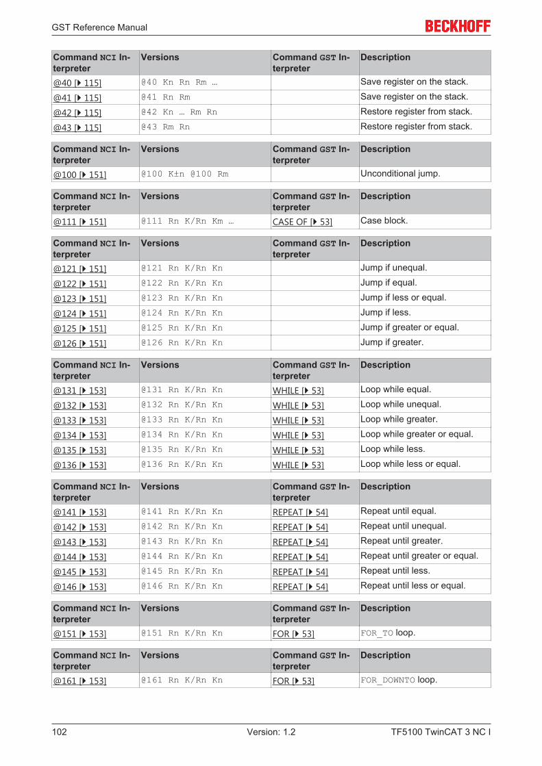
GST Reference Manual
TF5100 TwinCAT 3 NC I102 Version: 1.2
Command NCI In-terpreter
Versions Command GST In-terpreter
Description
@40 [} 115] @40 Kn Rn Rm … Save register on the stack.
@41 [} 115] @41 Rn Rm Save register on the stack.
@42 [} 115] @42 Kn … Rm Rn Restore register from stack.
@43 [} 115] @43 Rm Rn Restore register from stack.
Command NCI In-terpreter
Versions Command GST In-terpreter
Description
@100 [} 151] @100 K±n @100 Rm Unconditional jump.
Command NCI In-terpreter
Versions Command GST In-terpreter
Description
@111 [} 151] @111 Rn K/Rn Km … CASE OF [} 53] Case block.
Command NCI In-terpreter
Versions Command GST In-terpreter
Description
@121 [} 151] @121 Rn K/Rn Kn Jump if unequal.
@122 [} 151] @122 Rn K/Rn Kn Jump if equal.
@123 [} 151] @123 Rn K/Rn Kn Jump if less or equal.
@124 [} 151] @124 Rn K/Rn Kn Jump if less.
@125 [} 151] @125 Rn K/Rn Kn Jump if greater or equal.
@126 [} 151] @126 Rn K/Rn Kn Jump if greater.
Command NCI In-terpreter
Versions Command GST In-terpreter
Description
@131 [} 153] @131 Rn K/Rn Kn WHILE [} 53] Loop while equal.
@132 [} 153] @132 Rn K/Rn Kn WHILE [} 53] Loop while unequal.
@133 [} 153] @133 Rn K/Rn Kn WHILE [} 53] Loop while greater.
@134 [} 153] @134 Rn K/Rn Kn WHILE [} 53] Loop while greater or equal.
@135 [} 153] @135 Rn K/Rn Kn WHILE [} 53] Loop while less.
@136 [} 153] @136 Rn K/Rn Kn WHILE [} 53] Loop while less or equal.
Command NCI In-terpreter
Versions Command GST In-terpreter
Description
@141 [} 153] @141 Rn K/Rn Kn REPEAT [} 54] Repeat until equal.
@142 [} 153] @142 Rn K/Rn Kn REPEAT [} 54] Repeat until unequal.
@143 [} 153] @143 Rn K/Rn Kn REPEAT [} 54] Repeat until greater.
@144 [} 153] @144 Rn K/Rn Kn REPEAT [} 54] Repeat until greater or equal.
@145 [} 153] @145 Rn K/Rn Kn REPEAT [} 54] Repeat until less.
@146 [} 153] @146 Rn K/Rn Kn REPEAT [} 54] Repeat until less or equal.
Command NCI In-terpreter
Versions Command GST In-terpreter
Description
@151 [} 153] @151 Rn K/Rn Kn FOR [} 53] FOR_TO loop.
Command NCI In-terpreter
Versions Command GST In-terpreter
Description
@161 [} 153] @161 Rn K/Rn Kn FOR [} 53] FOR_DOWNTO loop.
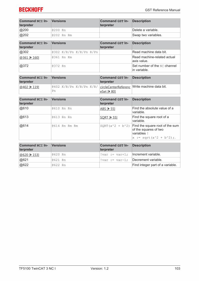
GST Reference Manual
TF5100 TwinCAT 3 NC I 103Version: 1.2
Command NCI In-terpreter
Versions Command GST In-terpreter
Description
@200 @200 Rn Delete a variable.@202 @202 Rn Rm Swap two variables.
Command NCI In-terpreter
Versions Command GST In-terpreter
Description
@302 @302 K/R/Pn K/R/Pn R/Pn Read machine data bit.
@361 [} 160] @361 Rn Km Read machine-related actualaxis value.
@372 @372 Rn Set number of the NC channelin variable.
Command NCI In-terpreter
Versions Command GST In-terpreter
Description
@402 [} 119] @402 K/R/Pn K/R/Pn K/R/Pn
circleCenterReferenceSet [} 80]
Write machine data bit.
Command NCI In-terpreter
Versions Command GST In-terpreter
Description
@610 @610 Rn Rn ABS [} 55] Find the absolute value of avariable.
@613 @613 Rn Rn SQRT [} 55] Find the square root of avariable.
@614 @614 Rn Rm Rm SQRT(a^2 + b^2) Find the square root of the sumof the squares of twovariables !x := sqrt(a^2 + b^2);.
Command NCI In-terpreter
Versions Command GST In-terpreter
Description
@620 [} 153] @620 Rn !var := var+1; Increment variable.@621 @621 Rn !var := var-1; Decrement variable.@622 @622 Rn Find integer part of a variable.
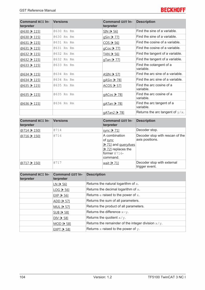
GST Reference Manual
TF5100 TwinCAT 3 NC I104 Version: 1.2
Command NCI In-terpreter
Versions Command GST In-terpreter
Description
@630 [} 115] @630 Rn Rm SIN [} 56] Find the sine of a variable.
@630 [} 115] @630 Rn Rm gSin [} 77] Find the sine of a variable.
@631 [} 115] @631 Rn Rm COS [} 56] Find the cosine of a variable.
@631 [} 115] @631 Rn Rm gCos [} 77] Find the cosine of a variable.
@632 [} 115] @632 Rn Rm TAN [} 56] Find the tangent of a variable.
@632 [} 115] @632 Rn Rm gTan [} 77] Find the tangent of a variable.
@633 [} 115] @633 Rn Rm Find the cotangent of avariable.
@634 [} 115] @634 Rn Rm ASIN [} 57] Find the arc sine of a variable.
@634 [} 115] @634 Rn Rm gASin [} 78] Find the arc sine of a variable.
@635 [} 115] @635 Rn Rm ACOS [} 57] Find the arc cosine of avariable.
@635 [} 115] @635 Rn Rm gACos [} 78] Find the arc cosine of avariable.
@636 [} 115] @636 Rn Rm gATan [} 78] Find the arc tangent of avariable.
gATan2 [} 78] Returns the arc tangent of y/x.
Command NCI In-terpreter
Versions Command GST In-terpreter
Description
@714 [} 150] @714 sync [} 71] Decoder stop.
@716 [} 150] @716 A combinationof sync[} 71] and queryAxes[} 72] replaces theformer @716-command.
Decoder stop with rescan of theaxis positions.
@717 [} 150] @717 wait [} 71] Decoder stop with externaltrigger event.
Command NCI In-terpreter
Command GST In-terpreter
Description
LN [} 56] Returns the natural logarithm of x.
LOG [} 56] Returns the decimal logarithm of x.
EXP [} 56] Returns e raised to the power of x.
ADD [} 57] Returns the sum of all parameters.
MUL [} 57] Returns the product of all parameters.
SUB [} 58] Returns the difference x-y.
DIV [} 58] Returns the quotient x/y.
MOD [} 58] Returns the remainder of the integer division x/y.
EXPT [} 58] Returns x raised to the power of y.
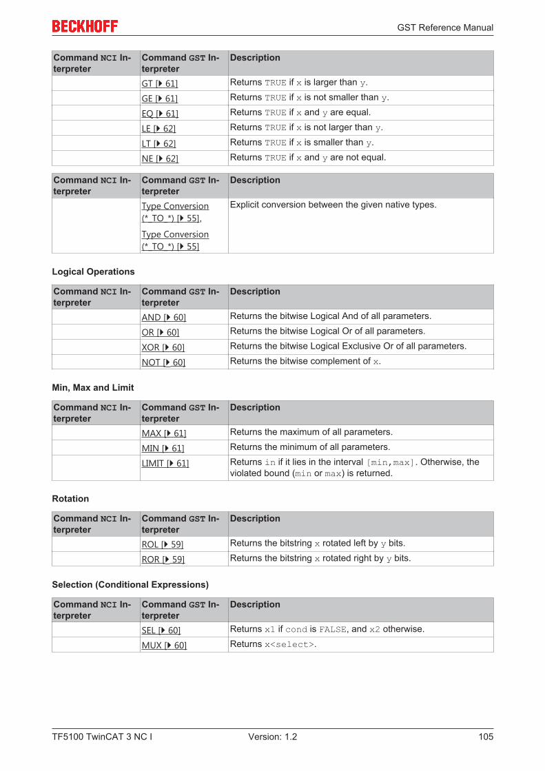
GST Reference Manual
TF5100 TwinCAT 3 NC I 105Version: 1.2
Command NCI In-terpreter
Command GST In-terpreter
Description
GT [} 61] Returns TRUE if x is larger than y.
GE [} 61] Returns TRUE if x is not smaller than y.
EQ [} 61] Returns TRUE if x and y are equal.
LE [} 62] Returns TRUE if x is not larger than y.
LT [} 62] Returns TRUE if x is smaller than y.
NE [} 62] Returns TRUE if x and y are not equal.
Command NCI In-terpreter
Command GST In-terpreter
Description
Type Conversion(*_TO_*) [} 55],
Type Conversion(*_TO_*) [} 55]
Explicit conversion between the given native types.
Logical Operations
Command NCI In-terpreter
Command GST In-terpreter
Description
AND [} 60] Returns the bitwise Logical And of all parameters.
OR [} 60] Returns the bitwise Logical Or of all parameters.
XOR [} 60] Returns the bitwise Logical Exclusive Or of all parameters.
NOT [} 60] Returns the bitwise complement of x.
Min, Max and Limit
Command NCI In-terpreter
Command GST In-terpreter
Description
MAX [} 61] Returns the maximum of all parameters.
MIN [} 61] Returns the minimum of all parameters.
LIMIT [} 61] Returns in if it lies in the interval [min,max]. Otherwise, theviolated bound (min or max) is returned.
Rotation
Command NCI In-terpreter
Command GST In-terpreter
Description
ROL [} 59] Returns the bitstring x rotated left by y bits.
ROR [} 59] Returns the bitstring x rotated right by y bits.
Selection (Conditional Expressions)
Command NCI In-terpreter
Command GST In-terpreter
Description
SEL [} 60] Returns x1 if cond is FALSE, and x2 otherwise.
MUX [} 60] Returns x<select>.
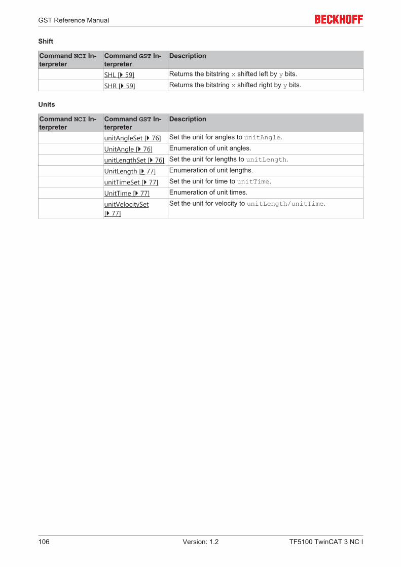
GST Reference Manual
TF5100 TwinCAT 3 NC I106 Version: 1.2
Shift
Command NCI In-terpreter
Command GST In-terpreter
Description
SHL [} 59] Returns the bitstring x shifted left by y bits.
SHR [} 59] Returns the bitstring x shifted right by y bits.
Units
Command NCI In-terpreter
Command GST In-terpreter
Description
unitAngleSet [} 76] Set the unit for angles to unitAngle.
UnitAngle [} 76] Enumeration of unit angles.
unitLengthSet [} 76] Set the unit for lengths to unitLength.
UnitLength [} 77] Enumeration of unit lengths.
unitTimeSet [} 77] Set the unit for time to unitTime.
UnitTime [} 77] Enumeration of unit times.
unitVelocitySet[} 77]
Set the unit for velocity to unitLength/unitTime.
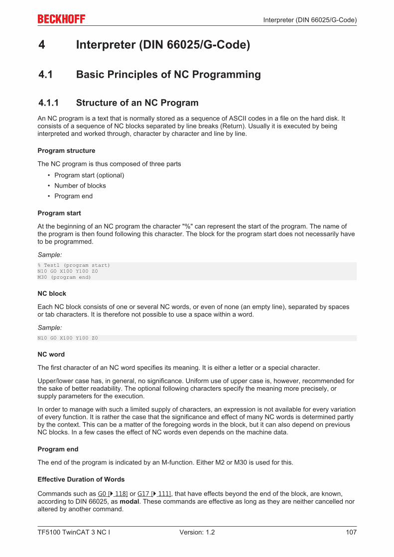
Interpreter (DIN 66025/G-Code)
TF5100 TwinCAT 3 NC I 107Version: 1.2
4 Interpreter (DIN 66025/G-Code)
4.1 Basic Principles of NC Programming
4.1.1 Structure of an NC ProgramAn NC program is a text that is normally stored as a sequence of ASCII codes in a file on the hard disk. Itconsists of a sequence of NC blocks separated by line breaks (Return). Usually it is executed by beinginterpreted and worked through, character by character and line by line.
Program structure
The NC program is thus composed of three parts
• Program start (optional)• Number of blocks• Program end
Program start
At the beginning of an NC program the character "%" can represent the start of the program. The name ofthe program is then found following this character. The block for the program start does not necessarily haveto be programmed.
Sample:% Test1 (program start)N10 G0 X100 Y100 Z0M30 (program end)
NC block
Each NC block consists of one or several NC words, or even of none (an empty line), separated by spacesor tab characters. It is therefore not possible to use a space within a word.
Sample:N10 G0 X100 Y100 Z0
NC word
The first character of an NC word specifies its meaning. It is either a letter or a special character.
Upper/lower case has, in general, no significance. Uniform use of upper case is, however, recommended forthe sake of better readability. The optional following characters specify the meaning more precisely, orsupply parameters for the execution.
In order to manage with such a limited supply of characters, an expression is not available for every variationof every function. It is rather the case that the significance and effect of many NC words is determined partlyby the context. This can be a matter of the foregoing words in the block, but it can also depend on previousNC blocks. In a few cases the effect of NC words even depends on the machine data.
Program end
The end of the program is indicated by an M-function. Either M2 or M30 is used for this.
Effective Duration of Words
Commands such as G0 [} 118] or G17 [} 111], that have effects beyond the end of the block, are known,according to DIN 66025, as modal. These commands are effective as long as they are neither cancelled noraltered by another command.
Interpreter (DIN 66025/G-Code)
TF5100 TwinCAT 3 NC I108 Version: 1.2
Comments
If either parts of an NC block, or the whole of it, is not to be interpreted, the region concerned is to be placedwithin curved brackets.
Sample:N10 G0 X100 (comment)
NOTE! A comment ends with the closing bracket, or, at the latest, at the end of the block. Thismeans that a comment can’t continue over a number of lines. Nested comments are also not possible.
Block numbers
Each block can be identified by a block number. The block number is accompanied by "N" for subordinateblocks and ":" for main blocks.
NOTE! The block number is not essential. A block not identified by a block number can not,however, be used as the target of a jump command. An error message, moreover, can onlyapproximately report the location of the error (the last block number).
4.1.2 Block SkippingIt is often useful if not all blocks of a program are always executed. This makes it possible to implementsimilar processes with a single program.
In such cases, the blocks that belong to one variant are given a block skipping identifier. This must be writtenat the start of the block, and consists of a slash "/".
If several variants are required, the slash is extended with line information (0..15), for instance "/12". The lineinformation (where "/" is equivalent to "/0") selects a bit from a word in the channel interface from the PLC tothe NC. If this bit is set, the block is not interpreted.
In the NC the variable 'mSkipLine' is evaluated for this purpose, which can be found among the inputs in thecyclic channel interface. The counterpart in the PLC can be found in the outputs under 'nSkipLine' [} 306](previously: nSkipBlock) (see TwinCAT PLC library: NCI Interpreter).
If one of a number of variants is to be active, all the other suppressions must be set. Then only those blocksremain active that have either no identifier, or that have the desired identifier.
Note
Active time of block skippingThe interpreter works an indeterminate number of blocks in advance of the execution.Block skipping can only operate correctly if it is set early enough (perhaps before the pro-gram starts), or if the interpreter is synchronized with the execution at a suitable location inthe program (decoder stop [} 150]).
4.1.3 Look-AheadThe actual velocity at the segment transition depends on a range of parameters. These include residual pathlength, dynamic parameters for the current segment, and (indirectly) the geometric angle at the segmenttransition.
Dynamic look-ahead (referred to as look-ahead below) ensures that the velocity can remain as high aspossible at segment transitions. In the standard configuration 128 geometry entries are considered.
Without look-ahead the velocity is reduced to 0 at each segment transition (G60).
The number of geometry entries taken into account can be set in the DXD parameters [} 25].
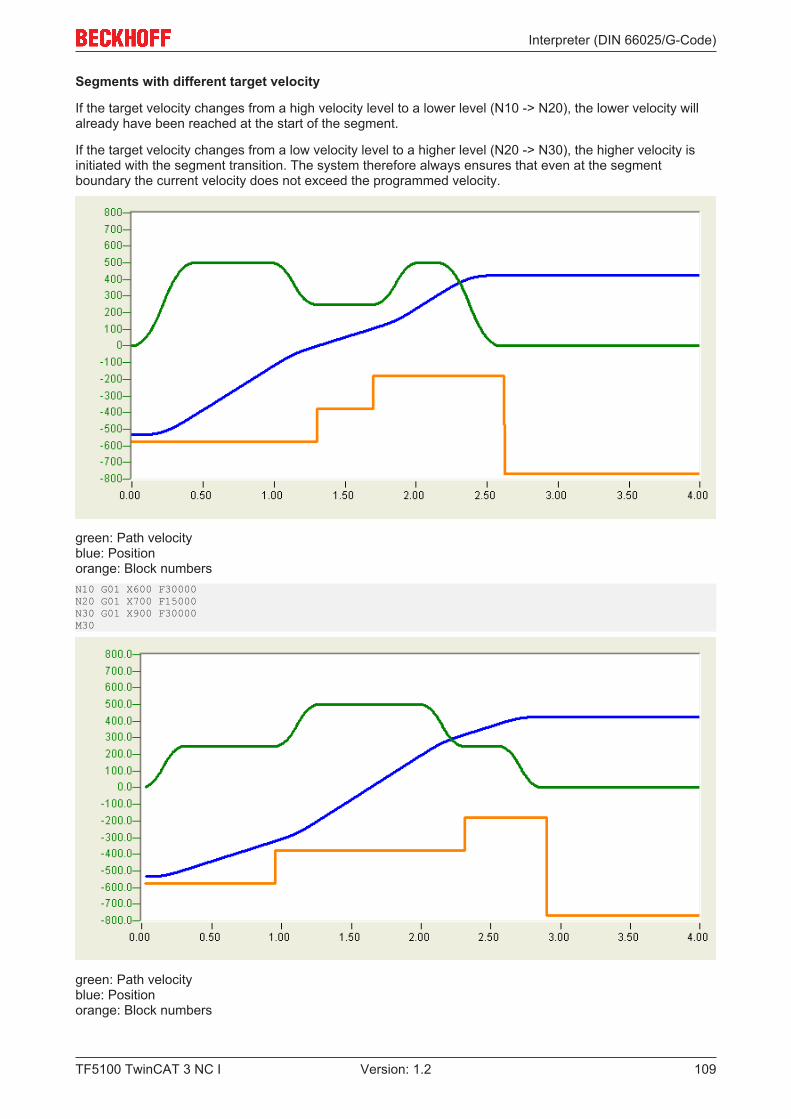
Interpreter (DIN 66025/G-Code)
TF5100 TwinCAT 3 NC I 109Version: 1.2
Segments with different target velocity
If the target velocity changes from a high velocity level to a lower level (N10 -> N20), the lower velocity willalready have been reached at the start of the segment.
If the target velocity changes from a low velocity level to a higher level (N20 -> N30), the higher velocity isinitiated with the segment transition. The system therefore always ensures that even at the segmentboundary the current velocity does not exceed the programmed velocity.
green: Path velocityblue: Positionorange: Block numbersN10 G01 X600 F30000N20 G01 X700 F15000N30 G01 X900 F30000M30
green: Path velocityblue: Positionorange: Block numbers
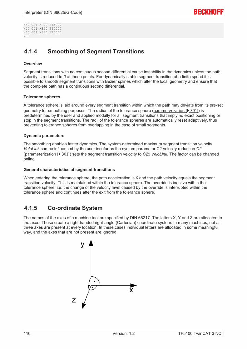
Interpreter (DIN 66025/G-Code)
TF5100 TwinCAT 3 NC I110 Version: 1.2
N40 G01 X200 F15000N50 G01 X800 F30000N60 G01 X900 F15000M30
4.1.4 Smoothing of Segment Transitions
Overview
Segment transitions with no continuous second differential cause instability in the dynamics unless the pathvelocity is reduced to 0 at those points. For dynamically stable segment transition at a finite speed it ispossible to smooth segment transitions with Bezier splines which alter the local geometry and ensure thatthe complete path has a continuous second differential.
Tolerance spheres
A tolerance sphere is laid around every segment transition within which the path may deviate from its pre-setgeometry for smoothing purposes. The radius of the tolerance sphere (parameterization [} 301]) ispredetermined by the user and applied modally for all segment transitions that imply no exact positioning orstop in the segment transitions. The radii of the tolerance spheres are automatically reset adaptively, thuspreventing tolerance spheres from overlapping in the case of small segments.
Dynamic parameters
The smoothing enables faster dynamics. The system-determined maximum segment transition velocityVeloLink can be influenced by the user insofar as the system parameter C2 velocity reduction C2(parameterization [} 301]) sets the segment transition velocity to C2x VeloLink. The factor can be changedonline.
General characteristics at segment transitions
When entering the tolerance sphere, the path acceleration is 0 and the path velocity equals the segmenttransition velocity. This is maintained within the tolerance sphere. The override is inactive within thetolerance sphere, i.e. the change of the velocity level caused by the override is interrupted within thetolerance sphere and continues after the exit from the tolerance sphere.
4.1.5 Co-ordinate SystemThe names of the axes of a machine tool are specified by DIN 66217. The letters X, Y and Z are allocated tothe axes. These create a right-handed right-angle (Cartesian) coordinate system. In many machines, not allthree axes are present at every location. In these cases individual letters are allocated in some meaningfulway, and the axes that are not present are ignored.

Interpreter (DIN 66025/G-Code)
TF5100 TwinCAT 3 NC I 111Version: 1.2
4.1.6 Dimensional NotationDimensional data can optionally be referred to an absolute origin or to the current set value.
Absolute dimensions
Command G90Cancellation G91
All positional data in absolute dimensions are always given with reference to the currently valid origin.
In terms of tool movement, this means that, under absolute dimensioning, it is the position to which the toolshould move that is described.
Incremental Dimensions
Command G91Cancellation G90
When dimensions are incremental, positional data is related to the immediately preceding point. In additionto the path axes, the auxiliary axes (Q1..Q5) are also taken into account.
For the tool movement this means that the incremental dimension describes by how much the tool is moved.
Units
The units for length, angle etc. are described in the following table:
UnitPositions and lengths mmAngle degreeTimes secFeed mm/min
4.1.7 Working Plane and Feed DirectionIn order to describe circles (except CIP [} 119]), and for the compensation of cutter radius [} 167] and toollength [} 164], it is necessary to specify the working plane.
Working Plane XY
Command G17Cancellation G18 or G19
The function G17 specifies the XY plane as the working plane and the feed direction as the Z direction.
The function acts as:
• Plane for tool radius compensation [} 167]
• Feed direction for tool length compensation [} 164] (offset)• Plane for circle interpolation
Note
Changing the working planeThe working plane cannot be changed while tool compensation is active.
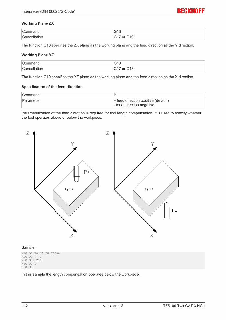
Interpreter (DIN 66025/G-Code)
TF5100 TwinCAT 3 NC I112 Version: 1.2
Working Plane ZX
Command G18Cancellation G17 or G19
The function G18 specifies the ZX plane as the working plane and the feed direction as the Y direction.
Working Plane YZ
Command G19Cancellation G17 or G18
The function G19 specifies the YZ plane as the working plane and the feed direction as the X direction.
Specification of the feed direction
Command PParameter + feed direction positive (default)
- feed direction negative
Parameterization of the feed direction is required for tool length compensation. It is used to specify whetherthe tool operates above or below the workpiece.
Sample:N10 G0 X0 Y0 Z0 F6000N20 D2 P- ZN30 G01 X100N40 D0 ZN50 M30
In this sample the length compensation operates below the workpiece.
Interpreter (DIN 66025/G-Code)
TF5100 TwinCAT 3 NC I 113Version: 1.2
4.1.8 Inch/metric dimensionsG70 Dimensions in inchesG71 Dimensions in millimeters (default)G700 Dimensions in inches with calculation of the feedG710 Dimensions in millimeters with calculation of the feed
Dimensions in millimeters (G71) is active by default. Information on whether the coordinates have to beconverted is stored in the machine parameters [} 11] (Interpreter tab). The basic dimension system inmillimeters is also set there by default.
The effects of the changeover
If the basic dimension system is not the same as the current dimension system (set with G70 or G71), thencertain parameters and co-ordinates must be converted. The conversion factor required here is stored in themachine parameters, like the basic dimension system. The changeover has effects on the followingparameters:
• Path information for the path axes (X, Y & Z)• Path information for the auxiliary axes (Q1..Q5)• Intermediate point co-ordinates (I, J, K)• Circle radii (B or U)• Programmable zero shift• Rounding radius (circle and spline smoothing)
There are also parameters that always remain in the basic dimension system, and are not converted.These include the
• adjustable zero shift• Tool data• feeds (except under G700 or G710)
Sample 1:
Basic dimension system: inch...N10 G71 (metric dimensions) N20 G01 X100 (conversion is carried out)N30 G70 (dimensions in inches)N40 G01 Y100 (conversion is not necessary, because).... (the basic dimensions are also inches)
Sample 2:
Basic dimension system: millimeters...N10 G71 (metric dimensions)N20 G01 X100 (conversion is not necessary, because) (the basic dimensions are also metric)N30 G70 (dimensions in inches)N40 G01 Y100 (conversion is carried out)
Zero shifts (NPV)
Adjustable zero shifts (G54-G57) always remain in the basic dimension system, and are not converted. Inthe case of the programmable zero shifts (G58 & G59) the effect depends on the current dimension systemwhen the shift is selected.
Sample 3:
Basic dimension system: millimeters...N10 G71 (mm - default)N20 G54 (activates adjustable zero offset shift)
Interpreter (DIN 66025/G-Code)
TF5100 TwinCAT 3 NC I114 Version: 1.2
N30 G58 X100 (programmable zero offset shift)N40 G01 X0 F6000 (the axis travels to 100 in the machine co-ordinate system)N50 G70 (inch)N60 G01 X0 (zero offset shift is programmed under G71 => zero offset shift remains unchanged) (i.e. the axis does not move)N70 G58 X100 (new programmable zero offset shift - now in inches)N80 G01 X0 (axis moves out by zero offset shift - to 2540 in the machine co-ordinate system)
4.1.9 Single Block OperationTo test a new NC program, the NCI can be switched to single block mode with the function blockItpSingleBlock [} 226]. When single block mode is active, the NC program is stopped after each line. Theuser has to acknowledge execution of the next line. This can be done by pressing 'NC start (F5)' in the XAEunder the Editor tab or by setting the input 'bTriggerNext' in the PLC function block ItpSingleBlock [} 226].
A distinction is made between two modes:
• Interpreter single block mode• NC kernel single block mode
Interpreter single block mode
If interpreter single block mode is active, the NC program is stopped after each line in the interpreter. Thisremains true even if the line only contains calculations, and no physical movement is programmed.This enables re-writing of R-parameters, for example.
Interpreter single block mode should be activated before the NC program is started. If this is not possible, anM-function can be reserved for the activation and combined with a decoder stop. If interpreter single block mode is activated during processing of the NC program without M-function anddecoder stop, it is impossible to predict when it will be active. Theoretically it is possible that the memories inthe NC kernel (SVB & SAF) are filled and contain more than 100 geometry entries. The single block can onlytake effect once these memories have been fully processed.
NC kernel single block mode
Like in interpreter single block mode, in NC kernel single block mode the NC blocks are executedindividually. The difference is that in NC kernel single block mode all entries (e.g. geometry entries) havealready passed through the interpreter. It is therefore not possible to overwrite R-parameters retrospectively,for example.
This operating mode has the advantage that single block mode can be enabled during processing of the NCprogram. If a geometry entry is executed (i.e. the axes are moved) during the activation, the system stops atthe next possible end of segment. This is usually the current segment. For activation after program startupno M-function with decoder stop is required.
If NC kernel single block mode is used in conjunction with blending, block relaying takes place in theblending sphere. The programmed blending continues to be executed (from TwinCAT V2.10 Build 1301).
Alternatives to activation
We recommend activating single block mode with ItpSingleBlock [} 226].
For reasons of compatibility with previous TwinCAT versions, single block mode can be activated via thecyclic channel interface.
Single block mode can be selected or deselected in the cyclic channel interface of the PLC. To this end thevariable 'nItpMode' has to be masked correctly in the PLC/NC channel interface.
Set bit 14 (0x4000) to switch on interpreter single block mode. Resetting the bit turns single block mode offagain.
It is also possible to trigger the single block from the PLC by means of this interface. Bit 15 must be set forthis. The effect is the same as activating NC start in the XAE.
Interpreter (DIN 66025/G-Code)
TF5100 TwinCAT 3 NC I 115Version: 1.2
4.1.10 Arithmetic ParametersThe arithmetic parameters (known as R-parameters for short) are interpreter variables that are named by anexpression of the form "R<n>". Since 'n' is an integer in the range 0..999, a total of 1000 R-parameters areavailable. Of these, the first 900 values (R0..R899) are local variables for the NC channel. They can only beaccessed by the channel’s interpreter. The R-parameters R900..R999 are declared globally. They exist onlyonce for each NC, and all channels access the same storage. This makes it possible to exchange data (e.g.for part tracing, collision avoidance etc.) over the channel boundaries.
Mathematical Calculations
The R-parameters (like the axis co-ordinates, feedrates etc.) are declared as variables of type 'double'. Thismakes full use of the computer’s arithmetic capacity. The number of places before and after the decimalpoint is not restricted by a format specification. The arithmetical resolution does, nevertheless, have a limit.In practice this is only visible in particularly critical cases. Examples of this include the differences of verylarge numbers that are almost equal, or trigonometrical functions in particular ranges of angles.
Assignment of R-ParametersN100 R5=17.5N110 R6=-4N120 R7=2.5 R8=1
As can be seen in the third line, it is quite possible to make more than one assignment in one block. Thisspeeds interpretation slightly, but it can be more difficult to localize an error in the line.
Calculation formula
A calculation formula is an extension of assignment. It consists of a target parameter, an assignment signand a series of values (R-parameters and constants) separated by arithmetical instructions.N100 R1=R2+R3-17.5*R9/2.5
Such a formula, contrary to normal mathematical practice, is processed strictly from left to right.
The illustrated formula is calculated as follows:
1. The contents of R2 is loaded into the arithmetic unit2. The contents of R3 is loaded into the arithmetic unit3. The arithmetic unit carries out the + instruction4. The value 17.5 is loaded into the arithmetic unit5. The arithmetic unit carries out the - instruction6. The contents of R9 is loaded into the arithmetic unit7. The arithmetic unit carries out the * instruction8. The value 2.5 is loaded into the arithmetic unit9. The arithmetic unit carries out the / instruction
10. The content of the arithmetic unit is stored in R-parameter R1
Mathematical functions
The interpreter provides standard computing functions. DIN 66025 does not specify any syntax here. Thecomputing functions are called via @6xx (see appendix - @-command overview [} 178]).
The trigonometrical functions are always calculated in degrees.
Sample:N10 R2=0 R3=45N20 @630 R2 R3
In this sample the sine of R3 is calculated in degrees. The result is then written into R2.
R-parameter access from the PLC
Interpreter (DIN 66025/G-Code)
TF5100 TwinCAT 3 NC I116 Version: 1.2
You can read the R-parameters into the PLC, or write the R-parameters from the PLC. Special PLC functionblocks are provided for this purpose
• ItpReadRParams [} 258]
• ItpWriteRParams [} 270]
During writing of the R-parameters, ensure that the interpreter is ahead of the block execution. In otherwords, writing of the R-parameters from the PLC should take place before the NC program starts or be linkedto a decoder stop [} 150].
For debugging purposes, all R-parameters can be written to a file at any time. This process can be triggeredvia ADS (see ADS interface - channel functions IndexOffset 0x24 & 0x25 [} 382]).
Other functions
RToDwordGetBit
This function converts an R-parameter to a DWord and then checks whether a particular bit is set. The resultis again stored in an R-parameter.
Command RToDwordGetBit[<dest>; <src>; <bit> ]Parameter <dest> R-parameter in which the result is enteredParameter <src> R-parameter containing the number that is to be
converted and checkedParameter <bit> Bit to be checked (0..31)
Sample:N10 R1=7N20 RToDwordGetBit[R2;R1;0]R10=31N30 RToDwordGetBit[R3;R1;R10]
Enter 1 in R2 and 0 in R3.
Initialization of R-parameters
'set RParam' is used to assign a value to a contiguous block of R-parameters.
Command #set RParam(<start index>; <count>; <value> )#Parameter <start index> Describes the first R-parameter to be writtenParameter <count> Number of R-parameters to be writtenParameter <value> Assigned value
Sample:N10 G01 X100 Y200 F6000N15 R2=3000N20 #set RParam( 1; 2; 0.0 )# (R2 is overwritten again here)N30 G01 X500
Saving R-Parameters
If the content of R-parameters [} 115] is required for subsequent use, while in the meantime the R-parameters are used for a different purpose, it can temporarily be stored in the values stack of the arithmeticunit.
Two possibilities exist for this:
• enumeration of the R-parameters• giving the range of R-parameters
Saving the values:
Interpreter (DIN 66025/G-Code)
TF5100 TwinCAT 3 NC I 117Version: 1.2
Command @40 <number> R<n> R<m>...@41 <1st R-parameter> <last R-parameter>
Restoring the values:
Command @42 <number> R<n> R<m>@43 <last R-parameter> <1st R-parameter>
When restoring the values, call the parameters in reverse order.
Sample 1:(saving the data) N100 @40 K4 R800 R810 R823 R4
N110 R800=4711N120 ...
(restoring the data)N200 @42 K4 R4 R823 R810 R800
Sample 2:(saving the data)N100 @41 R800 R805
N110 R800=4711N120 ...
(restoring the data)N200 @43 R805 R800
Note
Stack sizeThe value stack of the arithmetic unit has limited capacity. If it overflows, the NC program isinterrupted with an error message. That can occur as the value is saved, but can also occurin the course of subsequent formula evaluation.
4.2 Programming Movement Statements
4.2.1 ReferencingBy default, axis referencing (homing) should take place before the 3D-group is formed from the PTPchannel. Or it can be done from the NC program.
If axes are referenced in PTP mode, it can be done for several axes simultaneously. If axes are referencedfrom the NC program, it can only be done for one axis at a time.
Command G74Cancellation End of block
Sample:N10 G74 XN20 G74 Y
Note
Referencing with own blockReferencing must be carried out within its own block. G74 may only refer to one axis. Thiscommand is only applicable for the main axes (X,Y,Z).
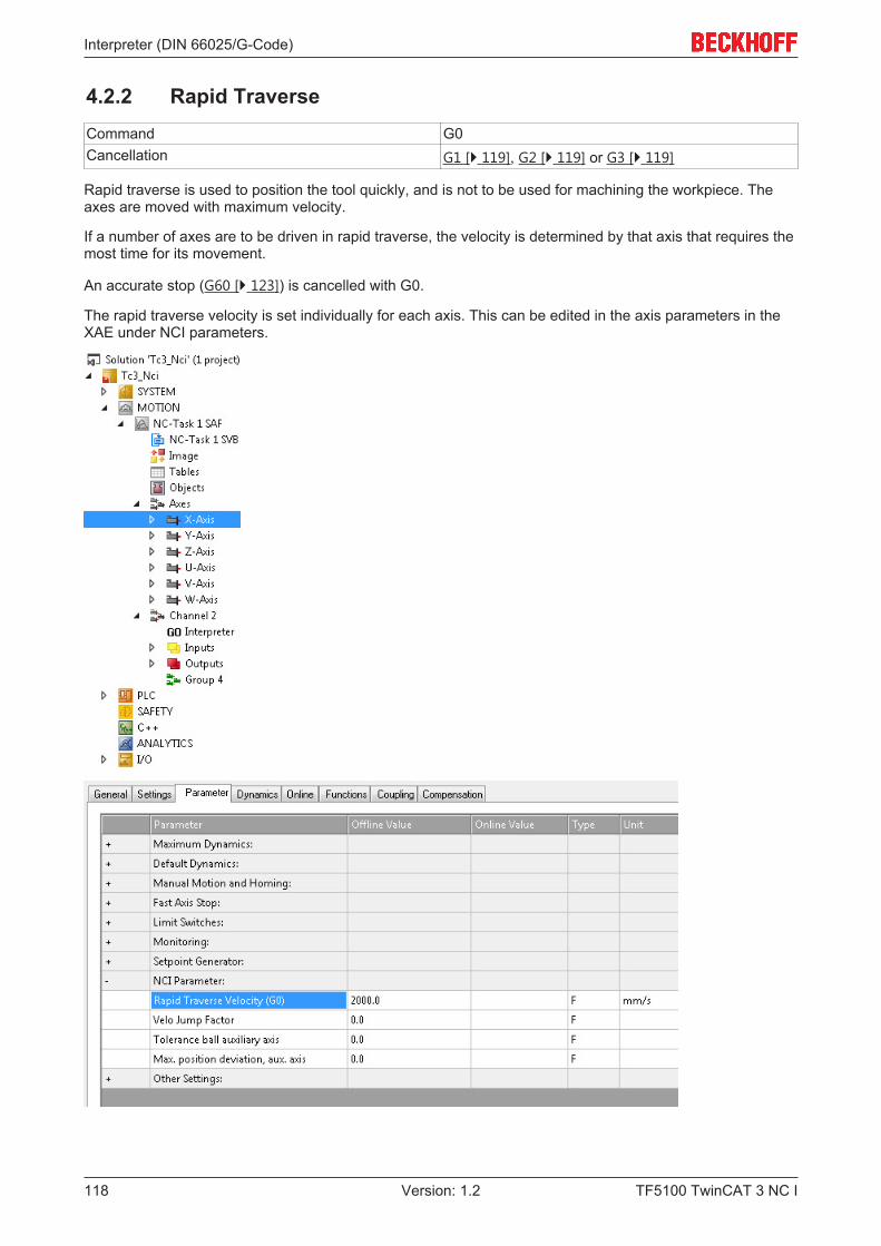
Interpreter (DIN 66025/G-Code)
TF5100 TwinCAT 3 NC I118 Version: 1.2
4.2.2 Rapid TraverseCommand G0Cancellation G1 [} 119], G2 [} 119] or G3 [} 119]
Rapid traverse is used to position the tool quickly, and is not to be used for machining the workpiece. Theaxes are moved with maximum velocity.
If a number of axes are to be driven in rapid traverse, the velocity is determined by that axis that requires themost time for its movement.
An accurate stop (G60 [} 123]) is cancelled with G0.
The rapid traverse velocity is set individually for each axis. This can be edited in the axis parameters in theXAE under NCI parameters.

Interpreter (DIN 66025/G-Code)
TF5100 TwinCAT 3 NC I 119Version: 1.2
4.2.3 Linear InterpolationCommand G1 or G01 (default)Cancellation G0 [} 118], G2 [} 119] or G3 [} 119]
Under linear interpolation the tool moves, with feedrate F, along a straight line that can be freely located inspace. The movement of the axes involved is completed at the same moment.
The feedrate (short: feed), F, describes the rate of displacement in millimeters per minute. This value iseffective globally, so that it is not necessary to program it again if the same feed is to be used later for othergeometrical movements.
Sample:N10 G90N20 G01 X100.1 Y200 F6000
In this example the axes are moved linearly to the position described. The Z axis is not mentioned in thisprogram, and therefore retains its old position.
4.2.4 Circular InterpolationCircular arcs can be programmed in a number of ways. Two types must be distinguished. One of these is anarc in the working plane [} 111] (e.g. the XY plane), and the other is an arc that can be freely located inspace (a CIP circle).
Clockwise circular interpolation
Command G2 or G02Cancellation G0 [} 118], G1 [} 119] or G3 [} 120]
Function G2 describes the path of a circular arc clockwise. This function requires the working plane [} 111]to have already been defined (G17 [} 111] by default).
In order to describe the circle unambiguously, further parameters are required in addition to the end point. Achoice is available between center point programming and radius programming.
Radius programming
In radius programming the radius of the circle is programmed as well as the end point. Either of the letters 'B'or 'U' may be used for the radius.
Since the direction is prescribed with G2, the circle is also unambiguously described. The starting point isdetermined by the foregoing geometrical movements.
Sample 1:N10 G01 G17 X100 Y100 F6000N20 G02 X200 B200
Note
Angle programming for angles >180°If an angle of more than 180° is to be traversed, the radius must be stated negatively.
Note
Full circle programmingThe start and the end points must be different, so that the center can be calculated. Radiusprogramming can therefore not be used for programming a full circle. Centre point pro-gramming can be used for this purpose.
Centre point programming
Centre point programming represents an alternative to the method that has just been described. Theadvantage of center point programming is that full circles can also be described in this way.
Interpreter (DIN 66025/G-Code)
TF5100 TwinCAT 3 NC I120 Version: 1.2
Under the standard settings, the center point is always given relatively to the starting point of the arc. Theparameters I, J and K are used for this purpose. With
• I for the X-component• J for the Y-component and• K for the Z-component.
At least one of these parameters is 0 and therefore does not have to be included in the program.
Sample 2:N10 G01 G17 X100 Y100 F6000N20 G02 I50 J0 (J is optional) X200N30 M30 (program end)
Sample 3:N10 G01 G18 X100 Y100 Z100 F6000N20 G02 I0 K50 X150 Z150 (quarter circle in ZX plane)N30 M30
By programming an item of machine data it is however also possible to enter the center point absolutely. Thecommand @402 is required for write access to a machine data bit.
In the following example, the circle from the first example is programmed using the absolute circle center.
Sample 4:N10 G01 G17 X100 Y100 F6000N20 @402 K5003 K5 K1 (centre point programming on)N30 G02 I150 J100 X200N40 @402 K5003 K5 K0 (centre point programming off)N50 M30
Anticlockwise Circular Interpolation
Command G3 or G03Cancellation G0 [} 118], G1 [} 119] or G2 [} 119]
The function G3 describes a circular arc anticlockwise. The parameters and entry possibilities are the sameas under G2.
Circular accuracy
Command #set paramRadiusPrec(<param>)#Parameter param: Maximum permitted radius tolerance
0.001 < param < 1.0 (default 0.1)
The 'set paramRadiusPrec' function is used to parameterize the required circular accuracy. This parameteraffects circles programmed with G02 or G03.
With center point programming, an error is generated if the difference in radius length is greater than<param>.
Centre point correction
Command CPCON (standard setting)Cancellation CPCOF
In center point programming the circle is overdetermined. For data consistency, the center point is usuallycorrected. Normally only a marginal modification of the center point is required. After the center pointcorrection, the magnitude of the input radius equals the output radius.
It the start and end point are very close together, the center point offset may be large. This may lead toproblems with automatically generated G-Code (postprocessor). For manually written G-Code, the CPCONsetting (center point correction on) is recommended.
Interpreter (DIN 66025/G-Code)
TF5100 TwinCAT 3 NC I 121Version: 1.2
CIP circle
Command CIPCancellation End of block
The circles discussed so far can only be used in the principal planes. The CIP circle can also be used toprogram a circle anywhere in space. For this purpose it is necessary to program not only an end point butalso some other point on the path.
So that the circle can be described unambiguously, it is necessary that the three points (the starting point isgiven implicitly) must not be collinear. It is thus not possible to program a full circle in this way.
I, J and K are available as path point parameters. By default their values are relative to the starting point of acircular path.
Sample 5:N10 G01 X100 Y100 F6000N20 CIP X200 Y200 I50 J50 K50
NOTE! For the CIP circle motion, cutter radius compensation [} 167] must not be active.
4.2.5 HelixIf a circular motion is superimposed onto a perpendicular linear movement, a helix is obtained. A helix canonly be programmed in the principal planes. The same parameters as are used for a circle in the principalplane are used. At the same time the axis that is perpendicular to the plane is driven.
The helix can be used together with the cutter radius compensation [} 167].
Sample:N10 G01 G17 X100 Y0 Z0 F6000N20 G03 I-50 Z100M30
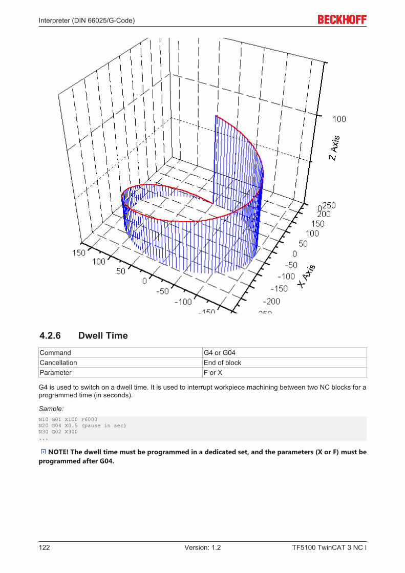
Interpreter (DIN 66025/G-Code)
TF5100 TwinCAT 3 NC I122 Version: 1.2
4.2.6 Dwell TimeCommand G4 or G04Cancellation End of blockParameter F or X
G4 is used to switch on a dwell time. It is used to interrupt workpiece machining between two NC blocks for aprogrammed time (in seconds).
Sample:N10 G01 X100 F6000N20 G04 X0.5 (pause in sec)N30 G02 X300...
NOTE! The dwell time must be programmed in a dedicated set, and the parameters (X or F) must beprogrammed after G04.
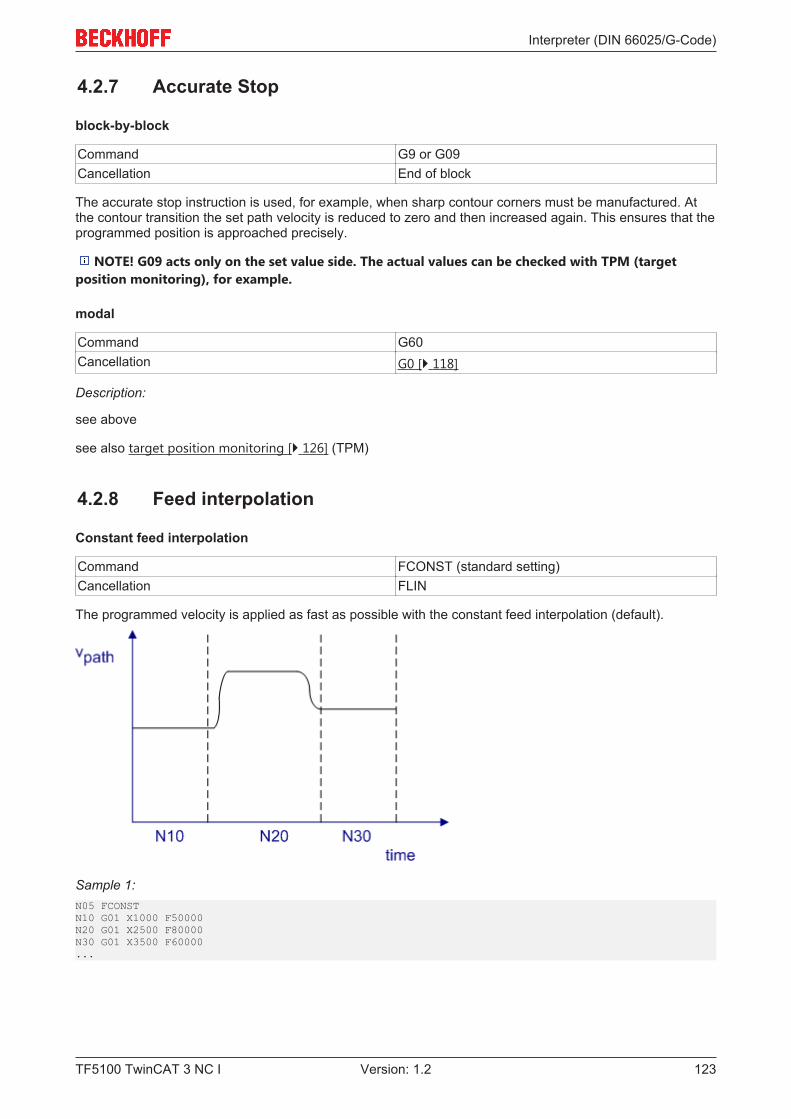
Interpreter (DIN 66025/G-Code)
TF5100 TwinCAT 3 NC I 123Version: 1.2
4.2.7 Accurate Stop
block-by-block
Command G9 or G09Cancellation End of block
The accurate stop instruction is used, for example, when sharp contour corners must be manufactured. Atthe contour transition the set path velocity is reduced to zero and then increased again. This ensures that theprogrammed position is approached precisely.
NOTE! G09 acts only on the set value side. The actual values can be checked with TPM (targetposition monitoring), for example.
modal
Command G60Cancellation G0 [} 118]
Description:
see above
see also target position monitoring [} 126] (TPM)
4.2.8 Feed interpolation
Constant feed interpolation
Command FCONST (standard setting)Cancellation FLIN
The programmed velocity is applied as fast as possible with the constant feed interpolation (default).
Sample 1:N05 FCONSTN10 G01 X1000 F50000N20 G01 X2500 F80000N30 G01 X3500 F60000...
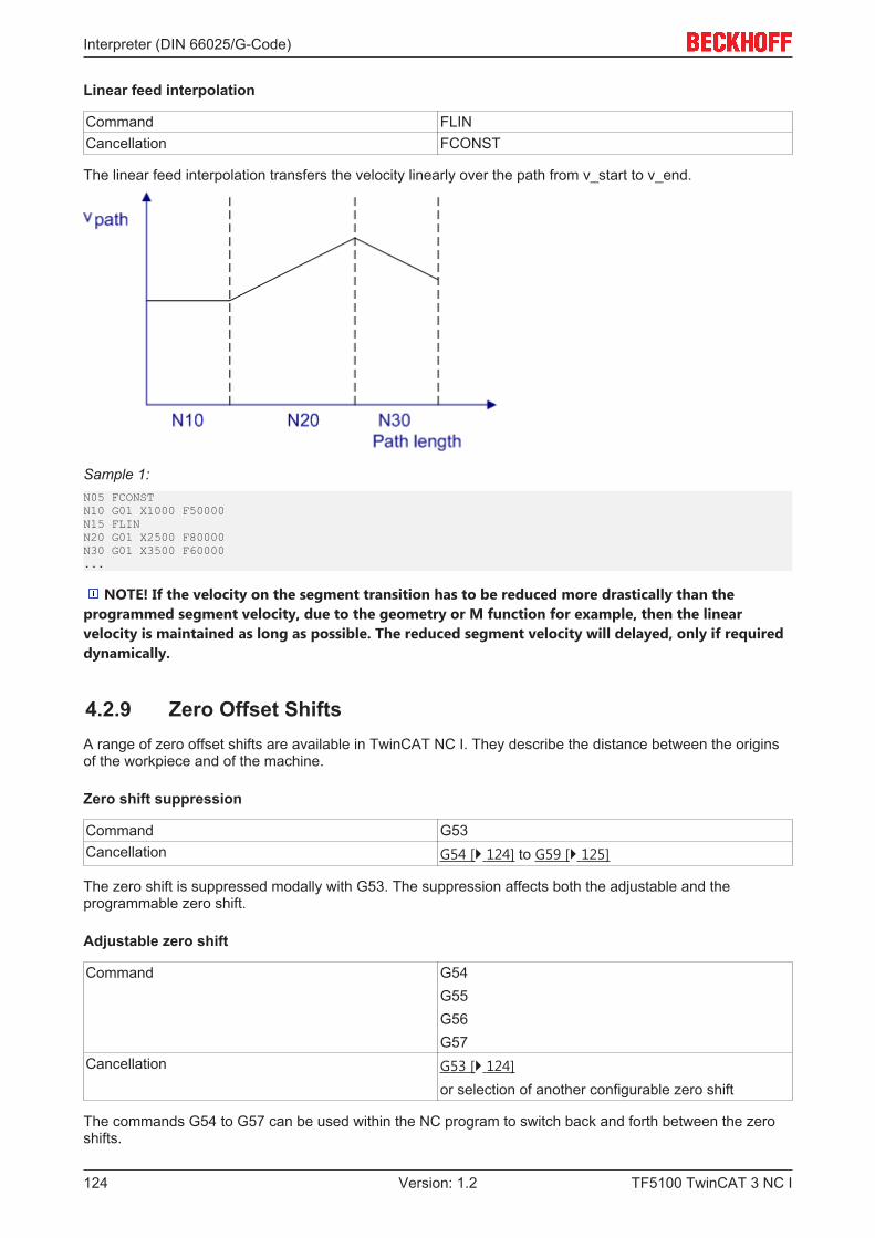
Interpreter (DIN 66025/G-Code)
TF5100 TwinCAT 3 NC I124 Version: 1.2
Linear feed interpolation
Command FLINCancellation FCONST
The linear feed interpolation transfers the velocity linearly over the path from v_start to v_end.
Sample 1:N05 FCONSTN10 G01 X1000 F50000N15 FLINN20 G01 X2500 F80000N30 G01 X3500 F60000...
NOTE! If the velocity on the segment transition has to be reduced more drastically than theprogrammed segment velocity, due to the geometry or M function for example, then the linearvelocity is maintained as long as possible. The reduced segment velocity will delayed, only if requireddynamically.
4.2.9 Zero Offset ShiftsA range of zero offset shifts are available in TwinCAT NC I. They describe the distance between the originsof the workpiece and of the machine.
Zero shift suppression
Command G53Cancellation G54 [} 124] to G59 [} 125]
The zero shift is suppressed modally with G53. The suppression affects both the adjustable and theprogrammable zero shift.
Adjustable zero shift
Command G54G55G56G57
Cancellation G53 [} 124]or selection of another configurable zero shift
The commands G54 to G57 can be used within the NC program to switch back and forth between the zeroshifts.

Interpreter (DIN 66025/G-Code)
TF5100 TwinCAT 3 NC I 125Version: 1.2
Parameterization
The configurable zero shift can be parameterized in different ways
1. PLC function block ItpWriteZeroShiftEx [} 231] (recommended standard)2. XAE Interpreter element [} 11]3. from the DIN-program
The parameters are saved for each interpolation channel. This means that the adjustable zero shifts arechannel dependent.
NOTE! The selection of a zero shift must be made in its own block. In order for the movementcorresponding to the shift to be actually made it is necessary that at least the axes involved are namedin a following geometrical block.
Sample 1:N10 G01 X100 Y0 Z0 F6000N20 G54 (activates adjustable zero offset shift (NPV))N30 G01 X Y ZN40 M30
In sample 1 all involved axes are named in line 30. The effect of this is that the zero shifts are applied to allthe axes.
Sample 2:N10 G01 X100 Y0 Z0 F6000N20 G54 (activates adjustable zero offset shift (NPV))N30 G01 X200 Y
In line 30 of sample 2 the X axis is taken to position 200 + shift in the X direction. The Y axis only moves toaccommodate the shift, and the Z axis is not moved.
Parameterization from the DIN program
Command #set paramZeroShift( G<n>; <value x>; <value y>;<value z> )#
Parameter G<n> Zero shift to be parameterized (G54..G59)Parameter <value> Coordinates of the zero shift
'#set paramZeroShift(..)#' parameterizes the zero shift but does not activate it. This requires explicitprogramming of the G-Code.
Sample 3:N10 G01 X100 Y0 Z0 F6000N20 R12=200N30 #set paramZeroShift( G54; 100.0; R12; -20)#N40 G54 (activates adjustable zero offset shift (NPV))N50 G01 X200 Y Z
Programmable zero shift
Command G58 or G59Cancellation G53 [} 124]
Programmable zero shifts exist in addition to the adjustable ones. This type of zero shift is directly describedfrom the NC program.
Note
Addition of zero shiftsThe programmable zero shift is only effective when the adjustable zero shift is active. Thismeans that the total shift is the sum of• set zero shift (G54, G55, G56 or G57)• first programmable zero shift (G58)• second programmable zero shift (G59)
Interpreter (DIN 66025/G-Code)
TF5100 TwinCAT 3 NC I126 Version: 1.2
Sample 4:N10 G01 X100 Y0 Z0 F6000N20 G54 (activates adjustable zero offset shift (NPV))N30 G58 X0.5 Y0.5 Z0.5 (1st prg. zero offset shift)N50 X Y Z (movements for the zero offset shift)...M30
Behavior with incremental dimension notation
Default behavior
Changing the origin also affects the incremental dimension.
Sample 5:N10 G01 X100 Y0 Z0 F6000N20 G54 (activates adjustable zero offset shift (NPV))N25 G58 X10 Y10 Z0N30 G91 (Incr. dimensions)N40 G01 X200 Y0N50 ...
In N40 Y moves to 10 in the basic coordinate system. A shift in origin also shifts the point of reference forincremental dimension programming, resulting in a travel path for Y.
In this way a contour, which is fully programmed based on the incremental dimension, can be positioned atany point through a zero shift.
The behavior of G91 is parameterizable.
Command DescriptionZeroShiftIncOn The zero shifts are also applied under G91 once the
axis is namedZeroShiftIncOff The zero shift is not applied under G91
Sample 6:N10 G01 X100 Y0 Z0 F6000N15 ZeroShiftIncOffN20 G54 (activates adjustable zero offset shift (NPV))N25 G58 X10 Y10 Z0N30 G91 (Incr. dimensions)N40 G01 X200 YN50 ...
Since 'ZeroShiftIncOff' is set in sample 6 , the X-axis in N40 is moved by 200 mm independently of the newzero shift. The Y-axis does not move as no target coordinate is programmed for it.
See also ToolOffsetIncOn/Off [} 164]
4.2.10 Target Position MonitoringCommand TPMCancellation End of block
The command 'TPM' is used to trigger target position monitoring from the NC program. At the end of thegeometry this always leads to an accurate stop on the set value side and subsequent checking of the targetposition window. Block relaying takes place when the monitoring conditions are met for all axes in the group.
Like for PTP, this function is enabled and parameterized individually for each axis. This means that differentlimits can be selected for auxiliary axes than for the path axes, for example.
Sample 1:N10 G01 X100 Y100 F6000N20 G01 X300 Y100 TPM...
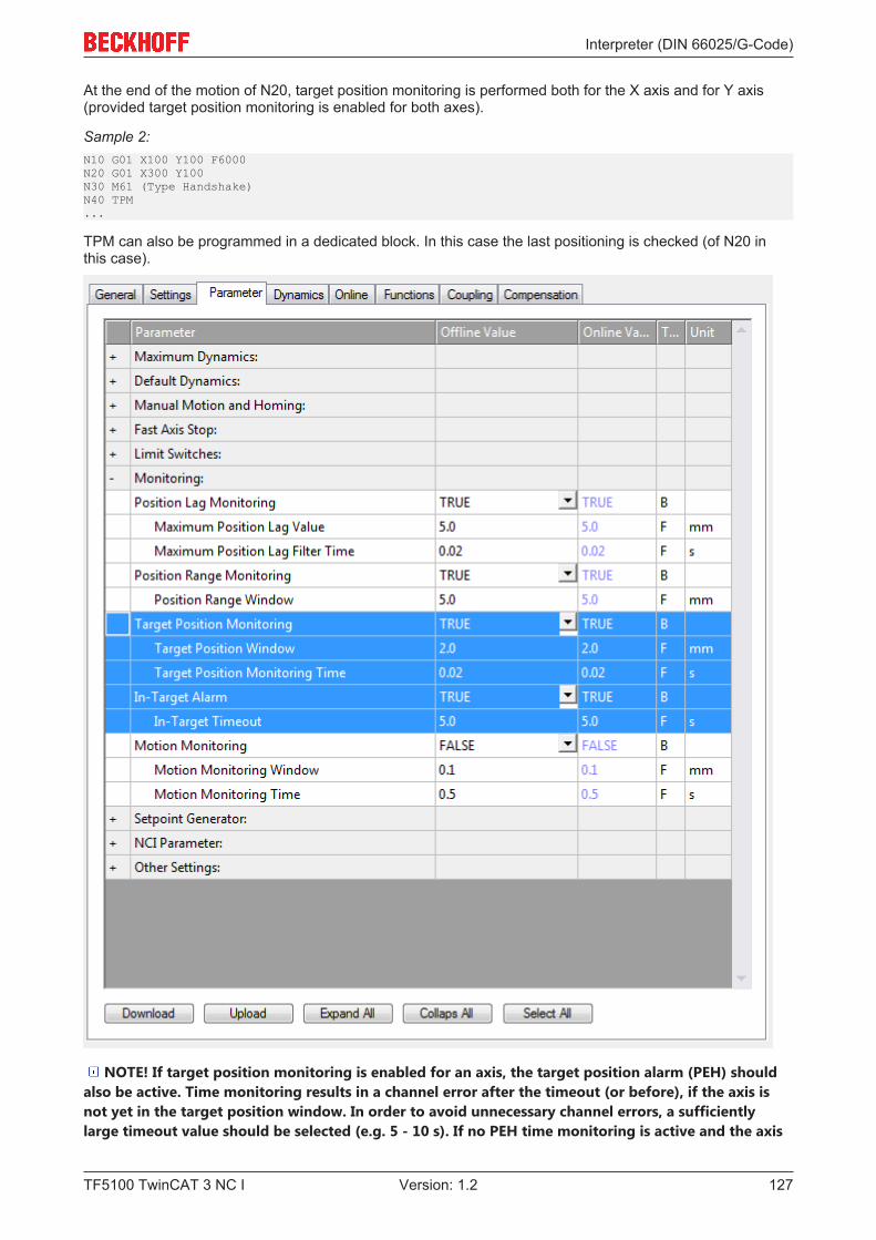
Interpreter (DIN 66025/G-Code)
TF5100 TwinCAT 3 NC I 127Version: 1.2
At the end of the motion of N20, target position monitoring is performed both for the X axis and for Y axis(provided target position monitoring is enabled for both axes).
Sample 2:N10 G01 X100 Y100 F6000N20 G01 X300 Y100N30 M61 (Type Handshake)N40 TPM...
TPM can also be programmed in a dedicated block. In this case the last positioning is checked (of N20 inthis case).
NOTE! If target position monitoring is enabled for an axis, the target position alarm (PEH) shouldalso be active. Time monitoring results in a channel error after the timeout (or before), if the axis isnot yet in the target position window. In order to avoid unnecessary channel errors, a sufficientlylarge timeout value should be selected (e.g. 5 - 10 s). If no PEH time monitoring is active and the axis
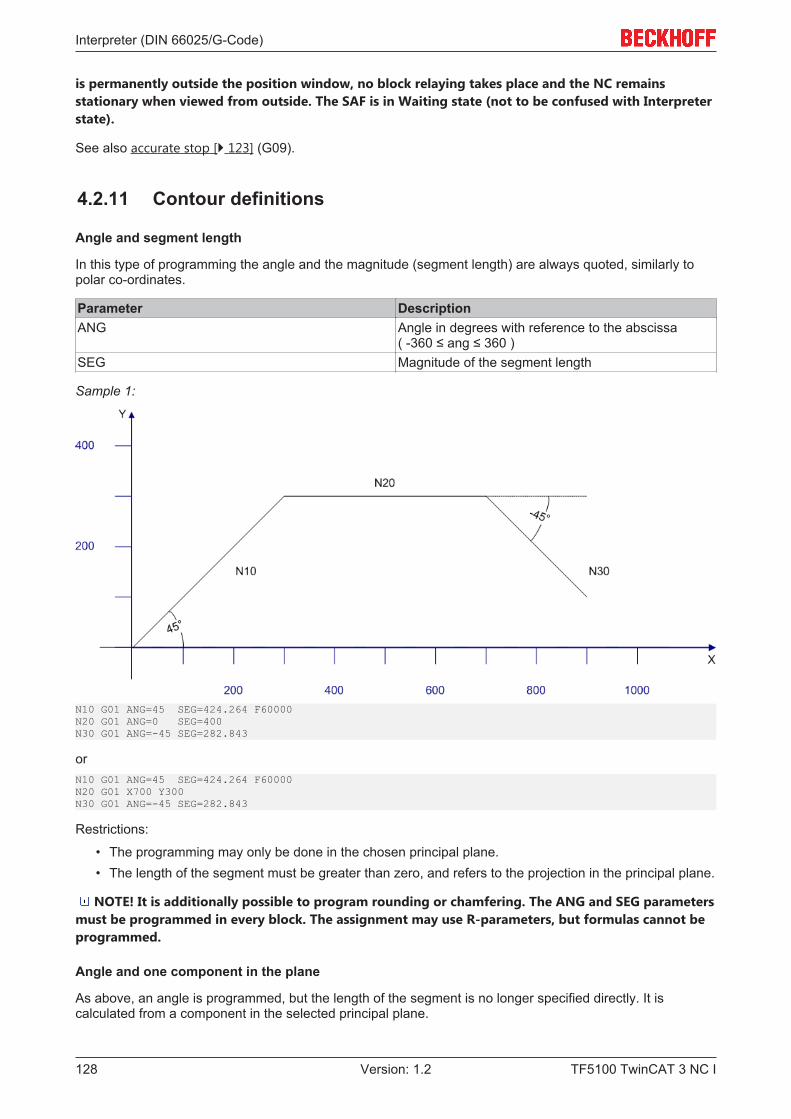
Interpreter (DIN 66025/G-Code)
TF5100 TwinCAT 3 NC I128 Version: 1.2
is permanently outside the position window, no block relaying takes place and the NC remainsstationary when viewed from outside. The SAF is in Waiting state (not to be confused with Interpreterstate).
See also accurate stop [} 123] (G09).
4.2.11 Contour definitions
Angle and segment length
In this type of programming the angle and the magnitude (segment length) are always quoted, similarly topolar co-ordinates.
Parameter DescriptionANG Angle in degrees with reference to the abscissa
( -360 ≤ ang ≤ 360 )SEG Magnitude of the segment length
Sample 1:
N10 G01 ANG=45 SEG=424.264 F60000N20 G01 ANG=0 SEG=400N30 G01 ANG=-45 SEG=282.843
orN10 G01 ANG=45 SEG=424.264 F60000N20 G01 X700 Y300N30 G01 ANG=-45 SEG=282.843
Restrictions:
• The programming may only be done in the chosen principal plane.• The length of the segment must be greater than zero, and refers to the projection in the principal plane.
NOTE! It is additionally possible to program rounding or chamfering. The ANG and SEG parametersmust be programmed in every block. The assignment may use R-parameters, but formulas cannot beprogrammed.
Angle and one component in the plane
As above, an angle is programmed, but the length of the segment is no longer specified directly. It iscalculated from a component in the selected principal plane.
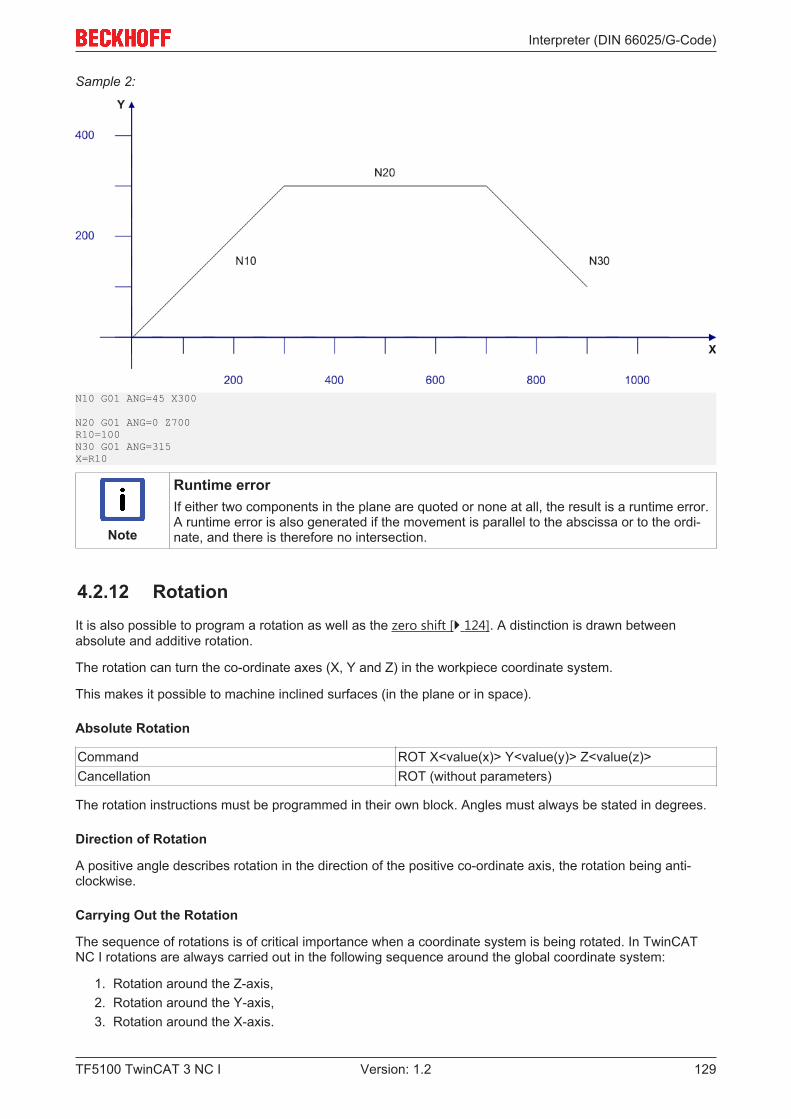
Interpreter (DIN 66025/G-Code)
TF5100 TwinCAT 3 NC I 129Version: 1.2
Sample 2:
N10 G01 ANG=45 X300
N20 G01 ANG=0 Z700R10=100N30 G01 ANG=315X=R10
Note
Runtime errorIf either two components in the plane are quoted or none at all, the result is a runtime error.A runtime error is also generated if the movement is parallel to the abscissa or to the ordi-nate, and there is therefore no intersection.
4.2.12 RotationIt is also possible to program a rotation as well as the zero shift [} 124]. A distinction is drawn betweenabsolute and additive rotation.
The rotation can turn the co-ordinate axes (X, Y and Z) in the workpiece coordinate system.
This makes it possible to machine inclined surfaces (in the plane or in space).
Absolute Rotation
Command ROT X<value(x)> Y<value(y)> Z<value(z)>Cancellation ROT (without parameters)
The rotation instructions must be programmed in their own block. Angles must always be stated in degrees.
Direction of Rotation
A positive angle describes rotation in the direction of the positive co-ordinate axis, the rotation being anti-clockwise.
Carrying Out the Rotation
The sequence of rotations is of critical importance when a coordinate system is being rotated. In TwinCATNC I rotations are always carried out in the following sequence around the global coordinate system:
1. Rotation around the Z-axis,2. Rotation around the Y-axis,3. Rotation around the X-axis.
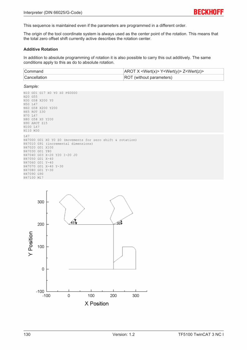
Interpreter (DIN 66025/G-Code)
TF5100 TwinCAT 3 NC I130 Version: 1.2
This sequence is maintained even if the parameters are programmed in a different order.
The origin of the tool coordinate system is always used as the center point of the rotation. This means thatthe total zero offset shift currently active describes the rotation center.
Additive Rotation
In addition to absolute programming of rotation it is also possible to carry this out additively. The sameconditions apply to this as do to absolute rotation.
Command AROT X <Wert(x)> Y<Wert(y)> Z<Wert(z)>Cancellation ROT (without parameters)
Sample:N10 G01 G17 X0 Y0 Z0 F60000N20 G55N30 G58 X200 Y0N50 L47N60 G58 X200 Y200N65 ROT Z30N70 L47N80 G58 X0 Y200N90 AROT Z15N100 L47N110 M30
L47N47000 G01 X0 Y0 Z0 (movements for zero shift & rotation)N47010 G91 (incremental dimensions)N47020 G01 X100N47030 G01 Y80N47040 G03 X-20 Y20 I-20 J0N47050 G01 X-40N47060 G01 Y-40N47070 G01 X-40 Y-30N47080 G01 Y-30N47090 G90N47100 M17
Interpreter (DIN 66025/G-Code)
TF5100 TwinCAT 3 NC I 131Version: 1.2
In this example, the same contour is traversed under different rotations. Since the contour (L47) isprogrammed in incremental dimensions, and the starting point is described by means of the programmedzero shift, the rotation is clear to see.
Note:
Once the ROT or AROT command has been programmed, the complete path vector (X, Y & Z) must beassigned.
Rotation extensions
In the default configuration the whole path vector must be programmed after each ROT command. Since thisis difficult to realize in some applications, this calculation can optionally be performed automatically in theinterpreter. To use this option, 'RotExOn' should be included at the start of the NC program.
Command RotExOnCancellation RotExOff
Sample:N10 RotExOn...N100 G54 (activate zero point & point of rotation)N110 ROT X90N120 G0 Z3 (preposition the tool)N130 G01 Z-10 F6000 (lower to cutting depth)N140 G01 X100N150 G01 Z3 (raise to preposition)...N1000 RotExOffN1010 M30
Calculate rotation
Command CalcRot[ R<s>; R<t>; R<u>]CalcInvRot[ R<s>; R<t>; R<u>]
Parameter The 3 R-parameters describe the vector to becalculated. The calculation will write the result intothis R-parameter, and the original value will thereforebe overwritten.
The function CalcRot rotates a three-dimensional vector through the current rotation angle. The rotationangles had been determined by ROT or AROT. The sequence of the calculation is the same as is used forthe rotation itself, that is Z, Y and X.
The CalcInvRot function behaves in precisely the opposite way. The signs of the currently valid rotationangles are inverted, and the order of calculation is X, Y and Z. In other words, the vector is turned back, soto speak.
Neither CalcRot nor CalcInvRot generate any geometry, but merely carry out the calculation of the vector.
Sample:N10 G01 X40 Y10 Z0 F6000 (the axes are movedwithout rotation)N20 R1=40 R2=10 R3=0
N30 ROT Z45
(What is the position to which X, Y, must be taken so that nomovement is executed?)N40 CalcInvRot[R1; R2; R3]N50 G01 X=R1 Y=R2 Z=R3 (R1=35.35 R2=-21.21 R3=0)N60 ...
Interpreter (DIN 66025/G-Code)
TF5100 TwinCAT 3 NC I132 Version: 1.2
Command RotVec[ R<x>; R<y>; R<z>; R<α>; R<β>; R<γ>]Parameter The 3 R-parameters (x..z) describe the vector to be
rotated through. The calculation will write the resultinto this R-parameter, and the original value willtherefore be overwritten.The last 3 R-parameters describe the angle.
The function RotVec rotates a three-dimensional vector through the specified angle. The order of therotation is Z, Y and X, like for ROT. RotVec is a calculation routine solely for rotating a vector. It has no effecton ROT or AROT.
4.2.13 MirrorThe mirror functionality changes the sign of named axes. This enables subroutines to be reused.
Mirroring
Command Mirror <opt. X> <opt. Y> <opt. Z>Cancellation Mirror (without parameters)
The mirror instructions must be programmed in a dedicated block. Mirrored axes must be named withoutfurther parameters.
Sample:N20 G54N30 G58 X100 Y100N40 L100
N50 G58 X-100 Y100N60 Mirror XN70 L100
N80 G58 X-50 Y-50N90 Mirror X YN100 L100
N110 G58 X10 Y-10N120 Mirror YN130 L100
N140 Mirror (turn off mirror)N150 G0 X0 y0M02
L100N1000 G0 X200 Y0 Z10 F60000 (move to start pos)N1020 G01 Z0N1030 G03 X200 Y100 J50N1040 G01 X50N1050 G01 Y400N1060 G01 X0N1070 G01 Y0N1080 G01 X200N1090 G01 Z10M17
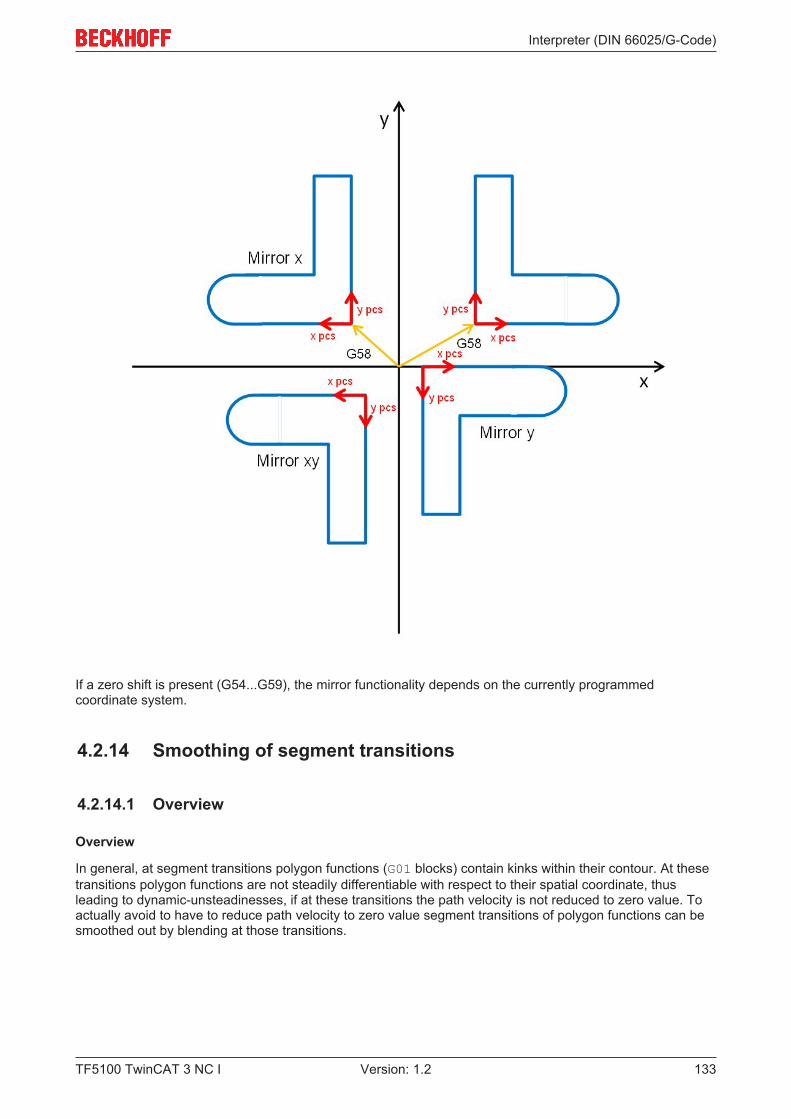
Interpreter (DIN 66025/G-Code)
TF5100 TwinCAT 3 NC I 133Version: 1.2
If a zero shift is present (G54...G59), the mirror functionality depends on the currently programmedcoordinate system.
4.2.14 Smoothing of segment transitions
4.2.14.1 Overview
Overview
In general, at segment transitions polygon functions (G01 blocks) contain kinks within their contour. At thesetransitions polygon functions are not steadily differentiable with respect to their spatial coordinate, thusleading to dynamic-unsteadinesses, if at these transitions the path velocity is not reduced to zero value. Toactually avoid to have to reduce path velocity to zero value segment transitions of polygon functions can besmoothed out by blending at those transitions.
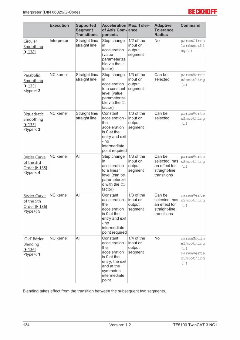
Interpreter (DIN 66025/G-Code)
TF5100 TwinCAT 3 NC I134 Version: 1.2
Execution SupportedSegmentTransitions
Accelerationof Axis Com-ponents
Max. Toler-ance
AdaptiveToleranceRadius
Command
CircularSmoothing[} 138]
Interpreter Straight line/straight line
Step changeinacceleration(valueparameterizable via the C1factor)
1/2 of theinput oroutputsegment
No paramCircularSmoothing(…)
ParabolicSmoothing[} 135]<type>: 2
NC kernel Straight line/straight line
Step changeinaccelerationto a constantlevel (valueparameterizable via the C1factor)
1/3 of theinput oroutputsegment
Can beselected
paramVertexSmoothing(…)
BiquadraticSmoothing[} 135]<type>: 3
NC kernel Straight line/straight line
Constantacceleration -theaccelerationis 0 at theentry and exit- nointermediatepoint required
1/3 of theinput oroutputsegment
Can beselected
paramVertexSmoothing(…)
Bézier Curveof the 3rdOrder [} 135]<type>: 4
NC kernel All Step changeinaccelerationto a linearlevel (can beparameterized with the C1factor)
1/3 of theinput oroutputsegment
Can beselected, hasan effect forstraight-linetransitions
paramVertexSmoothing(…)
Bézier Curveof the 5thOrder [} 136]<type>: 5
NC kernel All Constantacceleration -theaccelerationis 0 at theentry and exit- nointermediatepoint required
1/3 of theinput oroutputsegment
Can beselected, hasan effect forstraight-linetransitions
paramVertexSmoothing(…)
‘Old’ BézierBlending[} 136]<type>: 1
NC kernel All Constantacceleration -theaccelerationis 0 at theentry, the exitand at thesymmetricintermediatepoint
1/4 of theinput oroutputsegment
No paramSplineSmoothing(…)paramVertexSmoothing(…)
Blending takes effect from the transition between the subsequent two segments.
Interpreter (DIN 66025/G-Code)
TF5100 TwinCAT 3 NC I 135Version: 1.2
Note
Principle of BlendingThe radius of the tolerance sphere can be altered at any time within the NC program andcan be switched off again by setting the radius to 0. Blending remains active until the nextreset of the interpreter or a TwinCAT runtime restart.
4.2.14.2 Parabolic smoothing
Parabola smoothing
Command #set paramVertexSmoothing(<type>; <subtype>;<radius> )#
Parameter <type> For parabola smoothing: 2Parameter <subtype> 1: Constant tolerance radius [} 138]
2: Distance between intersection and vertex [} 138]3: Adaptive tolerance radius [} 138]
Parameter <radius> Max. radius of the tolerance sphere
For parabola smoothing a parabola is inserted geometrically into the segment transition. This ensures asteady velocity transition within the tolerance radius.
The parabola is only inserted for straight line/straight line transitions.
4.2.14.3 Biquadratic smoothing
Bi-quad smoothing
Command #set paramVertexSmoothing(<type>; <subtype>;<radius> )#
Parameter <type> For parabola smoothing: 3Parameter <subtype> 1: Constant tolerance radius [} 138]
2: Distance between intersection and vertex [} 138]3: Adaptive tolerance radius [} 138]
Parameter <radius> Max. radius of the tolerance sphere
With biquadratic smoothing there is no step change in acceleration in the axis components. With the sameradius, a smaller input velocity may therefore be required than for parabolic smoothing.
The operating principle of the subtypes is identical to that of the parabolic subtypes.
4.2.14.4 Bezier curve of the 3rd order
Bezier curve of the 3th order
Command #set paramVertexSmoothing(<type>; <subtype>;<radius> )#
Parameter <type> for the Bezier curve of the 3th order: 4Parameter <subtype> 1: Constant tolerance radius [} 138]
2: Distance between intersection and vertex [} 138]3: Adaptive tolerance radius [} 138]
Parameter <radius> Max. radius of the tolerance sphere
In case of the 3rd order Bezier curve a step change in acceleration appears in the axis components whenthe tolerance sphere is entered. The max. size is limited by the acceleration of the axis components and theC1 factor.
Interpreter (DIN 66025/G-Code)
TF5100 TwinCAT 3 NC I136 Version: 1.2
This blending can be used for all segment transitions. The subtypes 2 and 3 only work for straight line /straight line transitions.
Note
Acute angles at the segment transitionThe Bezier splines are generated by default, even at very acute angles. In order to avoidthe dynamic values being exceeded, a considerable reduction velocity is required in thiscase. However, since the dynamics are held constant in the spline, the movement acrossthe spline can be quite slow. In this case it is often practical to start the segment transitionwith an accurate stop. The command AutoAccurateStop [} 139] can be used to avoid hav-ing to calculate the angles manually.
4.2.14.5 Bezier curve of the 5th order
Bezier curve of the 5th order
Command #set paramVertexSmoothing(<type>; <subtype>;<radius> )#
Parameter <type> for the Bezier curve of the 5th order: 5Parameter <subtype> 1: Constant tolerance radius [} 138]
2: Distance between intersection and vertex [} 138]3: Adaptive tolerance radius [} 138]
Parameter <radius> Max. radius of the tolerance sphere
With 5th order Bezier blending, no step change in acceleration occurs in the axis components on entry intothe tolerance sphere. In other words, the path axis acceleration is always constant if blending is selected.
This blending can be used for all segment transitions. The subtypes 2 and 3 only work for straight line /straight line transitions.
Note
Acute angles at the segment transitionThe Bezier splines are generated by default, even at very acute angles. In order to avoidthe dynamic values being exceeded, a considerable reduction velocity is required in thiscase. However, since the dynamics are held constant in the spline, the movement acrossthe spline can be quite slow. In this case it is often practical to start the segment transitionwith an accurate stop. The command AutoAccurateStop [} 139] can be used to avoid hav-ing to calculate the angles manually.
4.2.14.6 Old Bezier blending type
Note
Functions for compatibility with existing projectsThese functions are provided for compatibility reasons. For new projects Bezier curve of the3rd order [} 135] or Bezier curve of the 5th order [} 136] should be used.
Old Bezier blending with paramVertexSmoothing
Command #set paramVertexSmoothing(<type>; <subtype>;<radius> )#
Parameter <type> For Bezier Spline smoothing: 1Parameter <subtype> For Bezier Spline smoothing: 1Parameter <radius> radius of the tolerance sphere
Sample 1:N10 R57=100#set paramVertexSmoothing(1; 1;R57)#
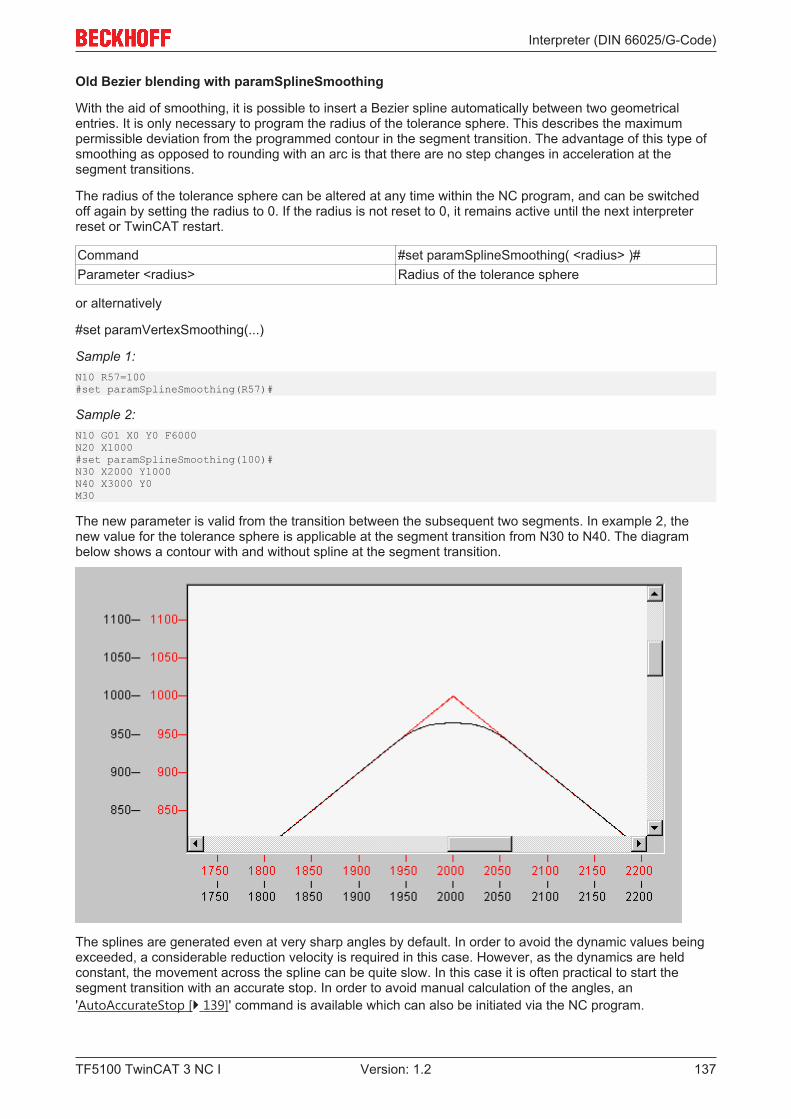
Interpreter (DIN 66025/G-Code)
TF5100 TwinCAT 3 NC I 137Version: 1.2
Old Bezier blending with paramSplineSmoothing
With the aid of smoothing, it is possible to insert a Bezier spline automatically between two geometricalentries. It is only necessary to program the radius of the tolerance sphere. This describes the maximumpermissible deviation from the programmed contour in the segment transition. The advantage of this type ofsmoothing as opposed to rounding with an arc is that there are no step changes in acceleration at thesegment transitions.
The radius of the tolerance sphere can be altered at any time within the NC program, and can be switchedoff again by setting the radius to 0. If the radius is not reset to 0, it remains active until the next interpreterreset or TwinCAT restart.
Command #set paramSplineSmoothing( <radius> )#Parameter <radius> Radius of the tolerance sphere
or alternatively
#set paramVertexSmoothing(...)
Sample 1:N10 R57=100#set paramSplineSmoothing(R57)#
Sample 2:N10 G01 X0 Y0 F6000N20 X1000#set paramSplineSmoothing(100)#N30 X2000 Y1000N40 X3000 Y0M30
The new parameter is valid from the transition between the subsequent two segments. In example 2, thenew value for the tolerance sphere is applicable at the segment transition from N30 to N40. The diagrambelow shows a contour with and without spline at the segment transition.
The splines are generated even at very sharp angles by default. In order to avoid the dynamic values beingexceeded, a considerable reduction velocity is required in this case. However, as the dynamics are heldconstant, the movement across the spline can be quite slow. In this case it is often practical to start thesegment transition with an accurate stop. In order to avoid manual calculation of the angles, an'AutoAccurateStop [} 139]' command is available which can also be initiated via the NC program.
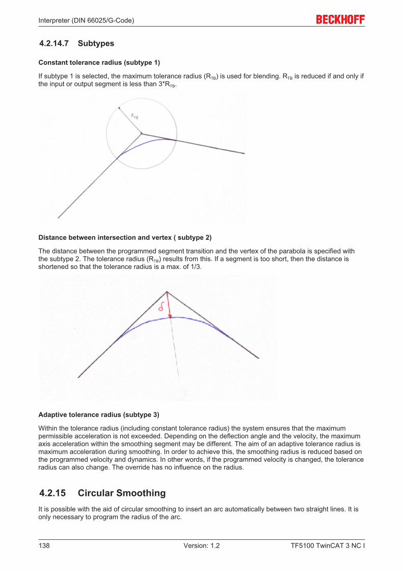
Interpreter (DIN 66025/G-Code)
TF5100 TwinCAT 3 NC I138 Version: 1.2
4.2.14.7 Subtypes
Constant tolerance radius (subtype 1)
If subtype 1 is selected, the maximum tolerance radius (RTB) is used for blending. RTB is reduced if and only ifthe input or output segment is less than 3*RTB.
Distance between intersection and vertex ( subtype 2)
The distance between the programmed segment transition and the vertex of the parabola is specified withthe subtype 2. The tolerance radius (RTB) results from this. If a segment is too short, then the distance isshortened so that the tolerance radius is a max. of 1/3.
Adaptive tolerance radius (subtype 3)
Within the tolerance radius (including constant tolerance radius) the system ensures that the maximumpermissible acceleration is not exceeded. Depending on the deflection angle and the velocity, the maximumaxis acceleration within the smoothing segment may be different. The aim of an adaptive tolerance radius ismaximum acceleration during smoothing. In order to achieve this, the smoothing radius is reduced based onthe programmed velocity and dynamics. In other words, if the programmed velocity is changed, the toleranceradius can also change. The override has no influence on the radius.
4.2.15 Circular SmoothingIt is possible with the aid of circular smoothing to insert an arc automatically between two straight lines. It isonly necessary to program the radius of the arc.
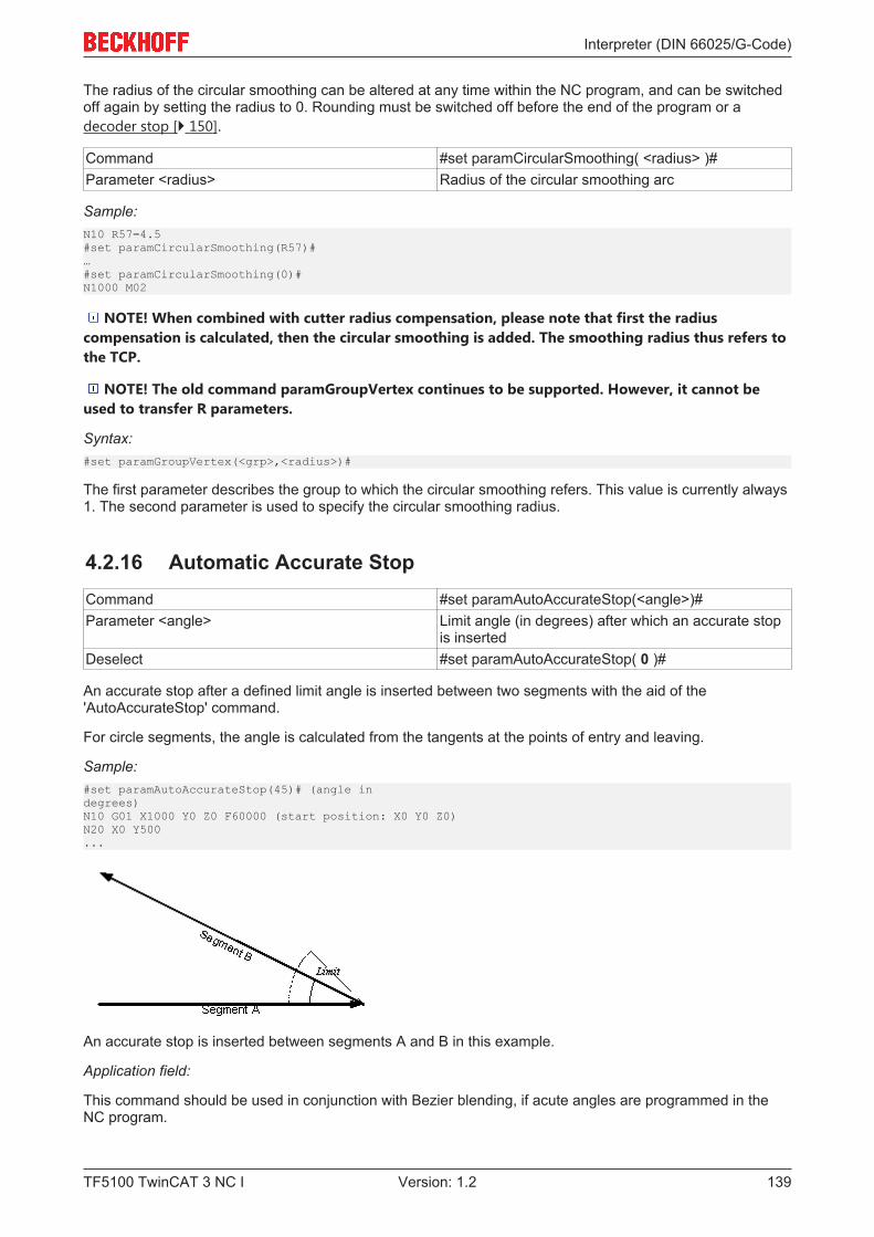
Interpreter (DIN 66025/G-Code)
TF5100 TwinCAT 3 NC I 139Version: 1.2
The radius of the circular smoothing can be altered at any time within the NC program, and can be switchedoff again by setting the radius to 0. Rounding must be switched off before the end of the program or adecoder stop [} 150].
Command #set paramCircularSmoothing( <radius> )#Parameter <radius> Radius of the circular smoothing arc
Sample:N10 R57=4.5#set paramCircularSmoothing(R57)#…#set paramCircularSmoothing(0)#N1000 M02
NOTE! When combined with cutter radius compensation, please note that first the radiuscompensation is calculated, then the circular smoothing is added. The smoothing radius thus refers tothe TCP.
NOTE! The old command paramGroupVertex continues to be supported. However, it cannot beused to transfer R parameters.
Syntax:#set paramGroupVertex(<grp>,<radius>)#
The first parameter describes the group to which the circular smoothing refers. This value is currently always1. The second parameter is used to specify the circular smoothing radius.
4.2.16 Automatic Accurate StopCommand #set paramAutoAccurateStop(<angle>)#Parameter <angle> Limit angle (in degrees) after which an accurate stop
is insertedDeselect #set paramAutoAccurateStop( 0 )#
An accurate stop after a defined limit angle is inserted between two segments with the aid of the'AutoAccurateStop' command.
For circle segments, the angle is calculated from the tangents at the points of entry and leaving.
Sample:#set paramAutoAccurateStop(45)# (angle indegrees)N10 G01 X1000 Y0 Z0 F60000 (start position: X0 Y0 Z0)N20 X0 Y500...
An accurate stop is inserted between segments A and B in this example.
Application field:
This command should be used in conjunction with Bezier blending, if acute angles are programmed in theNC program.
Interpreter (DIN 66025/G-Code)
TF5100 TwinCAT 3 NC I140 Version: 1.2
See also:
• Bezier curve of the 3th order [} 135]
• Bezier curve of the 5th order [} 136]
• 'Old' Bezier curve [} 136]
NOTE! This function has not yet been implemented for segment transitions with a helix.
4.2.17 Delete Distance to GoCommand DelDTGCancellation End of block
The DelDTG (delete distance to go) command is activated block by block via the NC program. Thiscommand enables deleting of the residual distance of the current geometry from the PLC with the functionblock ItpDelDtgEx [} 191]. In other words, if the command is issued while the block is processed, the motionis stopped with the usual deceleration ramps. The NC program then processes the next block. An errormessage is generated if the PLC command is not issued during the execution of a block with "deletedistance to go" selected.
The "delete distance to go" command always effects an implicit decoding stop, i.e. an exact positioningalways occurs at the end of the block.
Sample:N10 G01 X0 Y0 F6000N20 DelDTG G01 X2000N30 G01 X0
NOTE! DelDTG must not be active when cutter radius compensation is active.
4.2.18 Modulo MovementsCommand MOD[<axis and target modulo position>]Cancellation End of blockParameter 1 Axis for modulo operationParameter 2 Arithmetic sign for the direction of rotation (optional)Parameter 3 Modulo position
The modulo position is programmed in the same way as normal positioning.
The MOD command is effective for specific blocks, and must be explicitly programmed for every axis that isselected for modulo operation. The modulo position's arithmetic sign specifies the direction of rotation.
• Positive sign: The axes moves in the 'larger' direction• Negative sign: The axes moves in the 'smaller' direction• Exception: The axis cannot move to modulo -0, since zero has no sign

Interpreter (DIN 66025/G-Code)
TF5100 TwinCAT 3 NC I 141Version: 1.2
Sample 1:N10 G90N20 G01 MOD[X200] Y30 F600N30 G01 X200
N20 specifies a move in a positive direction for X to modulo position 200. Y moves to absolute position 30. Inblock N30, X is moved absolutely to position 200, i.e. not modulo.
Modulo movements of more than 360 degrees
The MOD command also allows movements of more than a 360 degrees to be made.
Modulo position = number of necessary rotations * 360 + modulo position
Sample 2:N10 G90N20 G01 X3610 F6000N30 R1=360N40 G01 MOD[X=R1+20]
In this example, the X axis moves 370 degrees to modulo position 20.
Restrictions and notes of for modulo movements:• No radius compensation may be active for the modulo axis.• No zero shift may be active for the modulo axis.
• During relative programming (G91 [} 111]) the modulo command is not evaluated, so that the axisreferred to in square brackets is treated as if the MOD command had not been given.
Modulo factor
The modulo factor is constant, and is 360.
4.2.19 Auxiliary axesAuxiliary axes (also known as Q axes) can be added to an interpolation group in addition to the actual pathaxes (X, Y & Z). The auxiliary axis can be seen as a type of slave for the path, i.e. it has no direct influenceon the path velocity. In addition to the 3 path axes, 5 auxiliary axes can also be interpolated for eachchannel.
Interpreter (DIN 66025/G-Code)
TF5100 TwinCAT 3 NC I142 Version: 1.2
The function block 'CfgBuildExt3DGroup [} 182] ' from the library Tc2_NCI, for example, may be used foradding to the interpolation group from the PLC.
Syntax
The auxiliary axes are addressed as Q1..Q5 from the part program. The numerical value may be assigneddirectly, or an R-parameter.
Sample 1:(start position X=Y=Z=Q1=0) N10 G01 X100 Q1=47.11 F6000...
If an NC block is programmed with one or more path axes and an auxiliary axis, both axes startsimultaneously and also reach the destination together.
Swiveling of the auxiliary axes
The term "swiveling of the auxiliary axes" is used if the path length within a motion set is zero. This is oftenthe case during 'swiveling' of a tool, with the feed angle relative to the contour being changed.
Since the path length is zero, there is no link to the path, and the movements of the auxiliary axes arecalculated via a virtual path. However, this has no influence on the real path of X, Y and Z, but here too allauxiliary axes are started simultaneously and also arrive at the destination simultaneously.
Here too, the velocity is specified via the F-parameter and now refers to the auxiliary axis with the greatesttravel distance.
Sample 1:(start position X=Y=Z=Q1=Q1=0)N10 G01 X100 F6000N20 Q1=100 Q2=200 F3000...
In N20, the velocity of Q2 is now 3000 and that of Q1 is 1500, since the travel distance is Q1=Q2/2.
4.2.19.1 Calculation of the velocity
Initially, only the path axes (X, Y and Z) are considered for the calculation of the path velocity.The path and the travel distance of the individual auxiliary axes result in a fixed coupling ratio for eachauxiliary axis within a segment. The target velocity of the auxiliary axis is thus also known. If this velocity isgreater than the permitted maximum velocity for this auxiliary axis, the path velocity is reduced until theupper speed limit is adhered to. In other words, exceeding of the velocity limits of the auxiliary axes also hasan indirect effect on the path velocity.
4.2.19.2 Path velocity at segment transitions
The reduction of the path velocity is explained below by means of an example. The contour of a stadium isparticularly suitable for this purpose. The aim is for the feed angle of a tool relative to the path tangent toremain constant.
On the stadium straight, the orientation of the tool remains constant, i.e. the tool is not turned. In contrast,the orientation relative to the base coordinate system must be changed continuously within the circle.Assuming the path velocity in the transition between straight and circle is not reduced to zero, a step changein velocity is inevitably generated for the swiveling axis (but not for the path axes!).
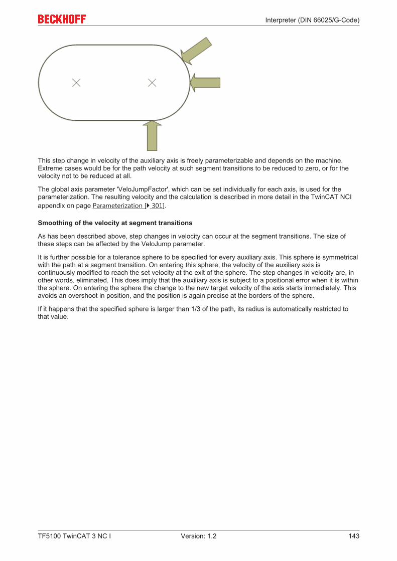
Interpreter (DIN 66025/G-Code)
TF5100 TwinCAT 3 NC I 143Version: 1.2
This step change in velocity of the auxiliary axis is freely parameterizable and depends on the machine.Extreme cases would be for the path velocity at such segment transitions to be reduced to zero, or for thevelocity not to be reduced at all.
The global axis parameter 'VeloJumpFactor', which can be set individually for each axis, is used for theparameterization. The resulting velocity and the calculation is described in more detail in the TwinCAT NCIappendix on page Parameterization [} 301].
Smoothing of the velocity at segment transitions
As has been described above, step changes in velocity can occur at the segment transitions. The size ofthese steps can be affected by the VeloJump parameter.
It is further possible for a tolerance sphere to be specified for every auxiliary axis. This sphere is symmetricalwith the path at a segment transition. On entering this sphere, the velocity of the auxiliary axis iscontinuously modified to reach the set velocity at the exit of the sphere. The step changes in velocity are, inother words, eliminated. This does imply that the auxiliary axis is subject to a positional error when it is withinthe sphere. On entering the sphere the change to the new target velocity of the axis starts immediately. Thisavoids an overshoot in position, and the position is again precise at the borders of the sphere.
If it happens that the specified sphere is larger than 1/3 of the path, its radius is automatically restricted tothat value.
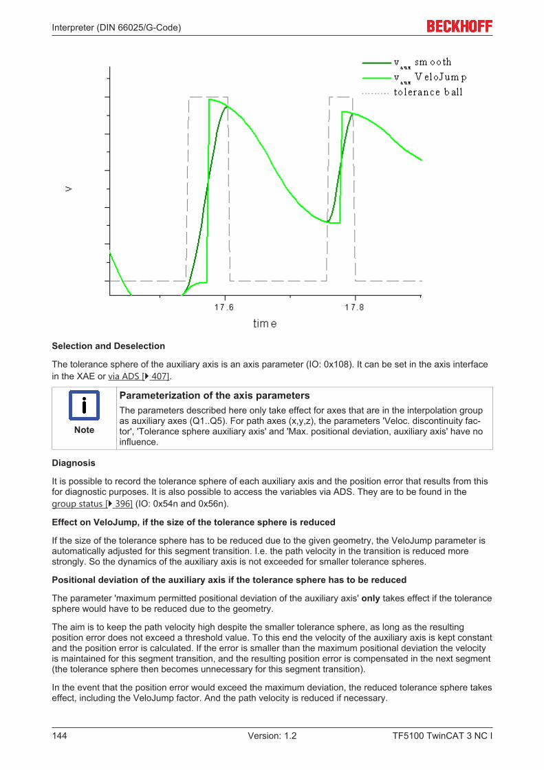
Interpreter (DIN 66025/G-Code)
TF5100 TwinCAT 3 NC I144 Version: 1.2
Selection and Deselection
The tolerance sphere of the auxiliary axis is an axis parameter (IO: 0x108). It can be set in the axis interfacein the XAE or via ADS [} 407].
Note
Parameterization of the axis parametersThe parameters described here only take effect for axes that are in the interpolation groupas auxiliary axes (Q1..Q5). For path axes (x,y,z), the parameters 'Veloc. discontinuity fac-tor', 'Tolerance sphere auxiliary axis' and 'Max. positional deviation, auxiliary axis' have noinfluence.
Diagnosis
It is possible to record the tolerance sphere of each auxiliary axis and the position error that results from thisfor diagnostic purposes. It is also possible to access the variables via ADS. They are to be found in thegroup status [} 396] (IO: 0x54n and 0x56n).
Effect on VeloJump, if the size of the tolerance sphere is reduced
If the size of the tolerance sphere has to be reduced due to the given geometry, the VeloJump parameter isautomatically adjusted for this segment transition. I.e. the path velocity in the transition is reduced morestrongly. So the dynamics of the auxiliary axis is not exceeded for smaller tolerance spheres.
Positional deviation of the auxiliary axis if the tolerance sphere has to be reduced
The parameter 'maximum permitted positional deviation of the auxiliary axis' only takes effect if the tolerancesphere would have to be reduced due to the geometry.
The aim is to keep the path velocity high despite the smaller tolerance sphere, as long as the resultingposition error does not exceed a threshold value. To this end the velocity of the auxiliary axis is kept constantand the position error is calculated. If the error is smaller than the maximum positional deviation the velocityis maintained for this segment transition, and the resulting position error is compensated in the next segment(the tolerance sphere then becomes unnecessary for this segment transition).
In the event that the position error would exceed the maximum deviation, the reduced tolerance sphere takeseffect, including the VeloJump factor. And the path velocity is reduced if necessary.

Interpreter (DIN 66025/G-Code)
TF5100 TwinCAT 3 NC I 145Version: 1.2
Sample 1:
Initial conditions:
• Set tolerance sphere: 5• Max. positional deviation: 1• The given geometry results in an effective tolerance sphere of 0.2, for example• The potential positional deviation is 0.3
Resultant behavior:
• The path velocity remains at a constant high level• The velocity of the auxiliary axis is kept constant• For this transition no tolerance sphere is required• The resulting positional deviation is compensated in the subsequent segment
Sample2:
Initial conditions:
• Set tolerance sphere: 5• Max. positional deviation: 1• The given geometry results in an effective tolerance sphere of 1.2, for example• The potential positional deviation is 1.1
Resultant behavior:
• The tolerance sphere is adjusted• The VeloJump parameter is adjusted• The path velocity is reduced at the segment transition• There is no positional deviation that has to be compensated
Parameterization
The parameterization of the maximum permitted positional deviation is an axis parameter [} 407]. By defaultthis feature is switched off (deviation = 0.0)
4.3 Supplementary Functions
4.3.1 M-Functions
Task: Signal exchange between NC and PLC
A range of equipment, such as collet chucks, drill drives, transport equipment etc. is best not driven directlyby the NC, but indirectly, using the PLC as an adapting and linking controller. This makes it easy to considerfeedback or safety conditions, without having to adapt the NC program, or even the NC system. The NC’s M-functions involve digital signal exchange: functions are switched on or off, activated or deactivated. Thetransfer of numerical working parameters is not provided for here, but can be implemented in other ways (H-functions [} 149], T-numbers [} 149] etc.).
4.3.1.1 Available M-functions
Number of M-functions
A total of 160 M-functions are available per channel
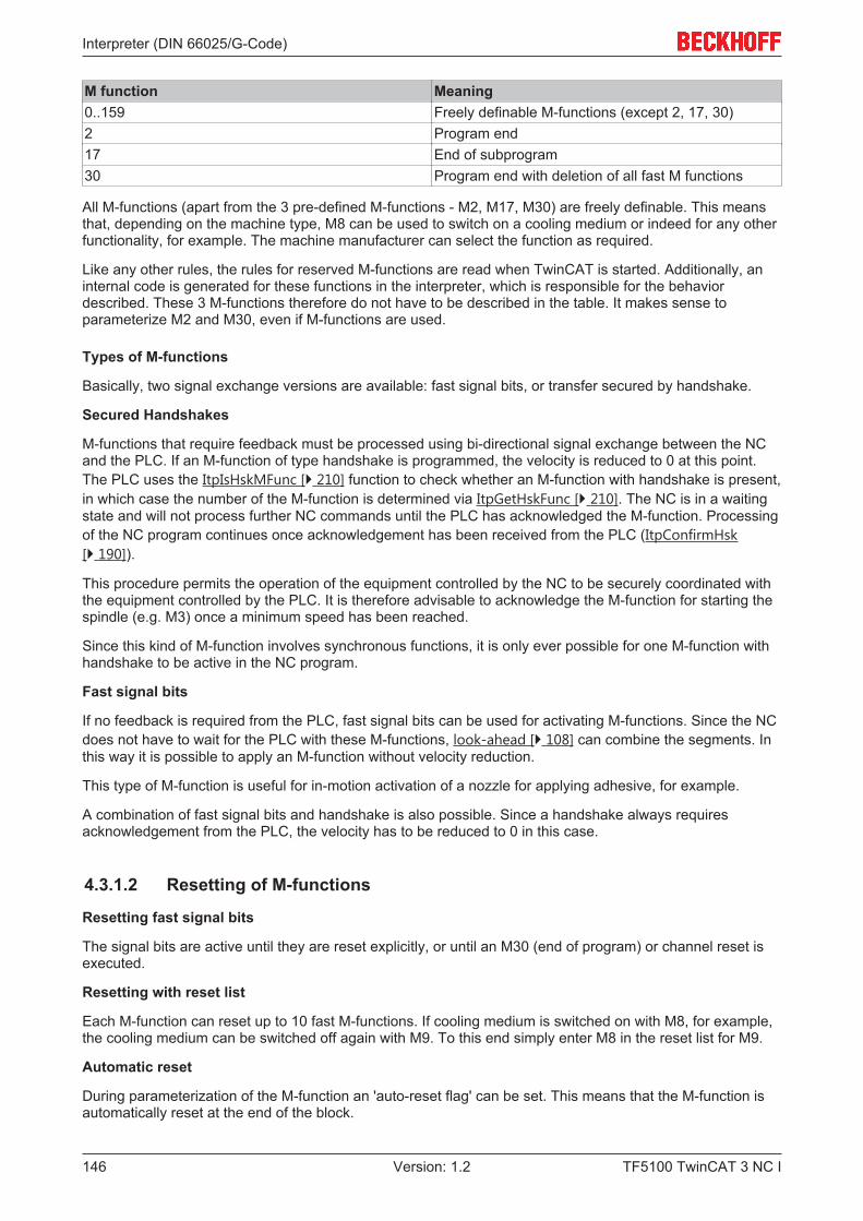
Interpreter (DIN 66025/G-Code)
TF5100 TwinCAT 3 NC I146 Version: 1.2
M function Meaning0..159 Freely definable M-functions (except 2, 17, 30)2 Program end17 End of subprogram30 Program end with deletion of all fast M functions
All M-functions (apart from the 3 pre-defined M-functions - M2, M17, M30) are freely definable. This meansthat, depending on the machine type, M8 can be used to switch on a cooling medium or indeed for any otherfunctionality, for example. The machine manufacturer can select the function as required.
Like any other rules, the rules for reserved M-functions are read when TwinCAT is started. Additionally, aninternal code is generated for these functions in the interpreter, which is responsible for the behaviordescribed. These 3 M-functions therefore do not have to be described in the table. It makes sense toparameterize M2 and M30, even if M-functions are used.
Types of M-functions
Basically, two signal exchange versions are available: fast signal bits, or transfer secured by handshake.
Secured Handshakes
M-functions that require feedback must be processed using bi-directional signal exchange between the NCand the PLC. If an M-function of type handshake is programmed, the velocity is reduced to 0 at this point.The PLC uses the ItpIsHskMFunc [} 210] function to check whether an M-function with handshake is present,in which case the number of the M-function is determined via ItpGetHskFunc [} 210]. The NC is in a waitingstate and will not process further NC commands until the PLC has acknowledged the M-function. Processingof the NC program continues once acknowledgement has been received from the PLC (ItpConfirmHsk[} 190]).
This procedure permits the operation of the equipment controlled by the NC to be securely coordinated withthe equipment controlled by the PLC. It is therefore advisable to acknowledge the M-function for starting thespindle (e.g. M3) once a minimum speed has been reached.
Since this kind of M-function involves synchronous functions, it is only ever possible for one M-function withhandshake to be active in the NC program.
Fast signal bits
If no feedback is required from the PLC, fast signal bits can be used for activating M-functions. Since the NCdoes not have to wait for the PLC with these M-functions, look-ahead [} 108] can combine the segments. Inthis way it is possible to apply an M-function without velocity reduction.
This type of M-function is useful for in-motion activation of a nozzle for applying adhesive, for example.
A combination of fast signal bits and handshake is also possible. Since a handshake always requiresacknowledgement from the PLC, the velocity has to be reduced to 0 in this case.
4.3.1.2 Resetting of M-functions
Resetting fast signal bits
The signal bits are active until they are reset explicitly, or until an M30 (end of program) or channel reset isexecuted.
Resetting with reset list
Each M-function can reset up to 10 fast M-functions. If cooling medium is switched on with M8, for example,the cooling medium can be switched off again with M9. To this end simply enter M8 in the reset list for M9.
Automatic reset
During parameterization of the M-function an 'auto-reset flag' can be set. This means that the M-function isautomatically reset at the end of the block.
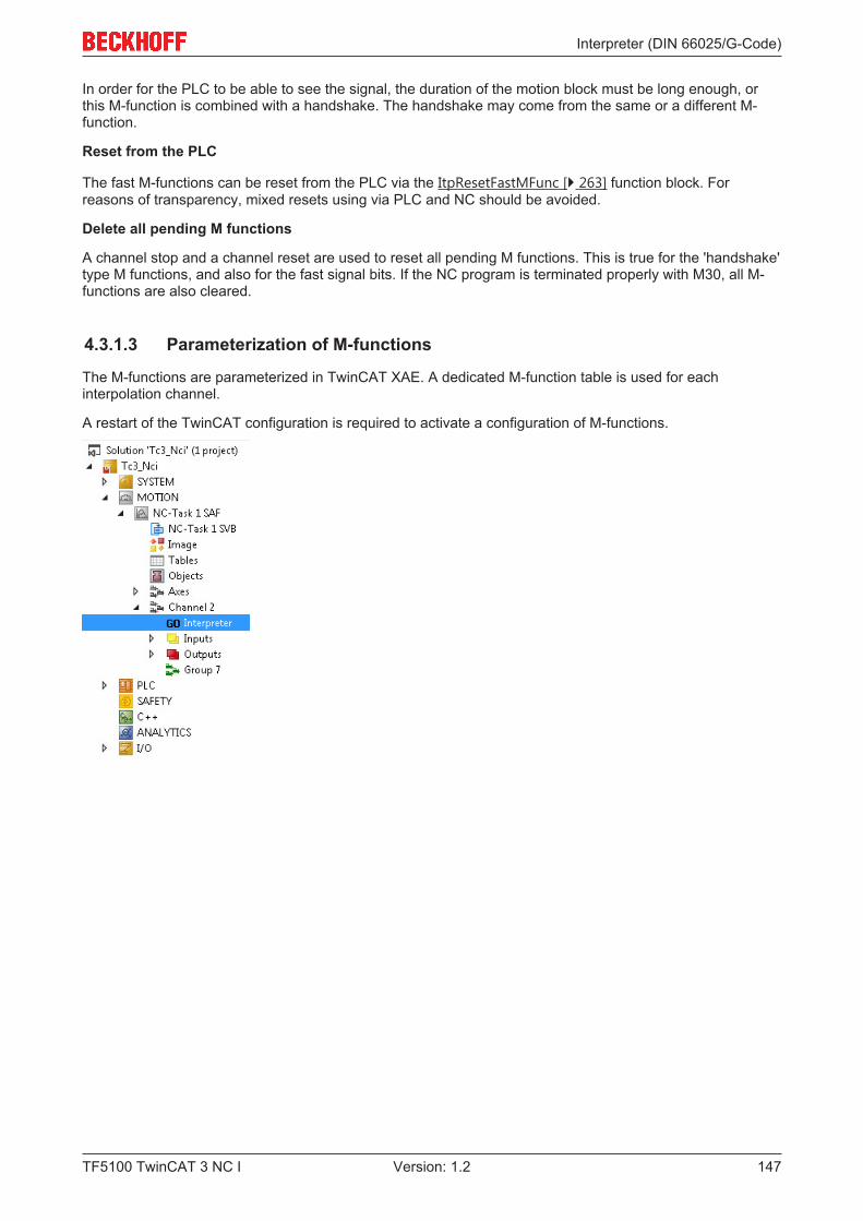
Interpreter (DIN 66025/G-Code)
TF5100 TwinCAT 3 NC I 147Version: 1.2
In order for the PLC to be able to see the signal, the duration of the motion block must be long enough, orthis M-function is combined with a handshake. The handshake may come from the same or a different M-function.
Reset from the PLC
The fast M-functions can be reset from the PLC via the ItpResetFastMFunc [} 263] function block. Forreasons of transparency, mixed resets using via PLC and NC should be avoided.
Delete all pending M functions
A channel stop and a channel reset are used to reset all pending M functions. This is true for the 'handshake'type M functions, and also for the fast signal bits. If the NC program is terminated properly with M30, all M-functions are also cleared.
4.3.1.3 Parameterization of M-functions
The M-functions are parameterized in TwinCAT XAE. A dedicated M-function table is used for eachinterpolation channel.
A restart of the TwinCAT configuration is required to activate a configuration of M-functions.
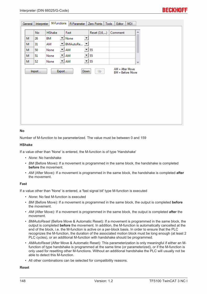
Interpreter (DIN 66025/G-Code)
TF5100 TwinCAT 3 NC I148 Version: 1.2
No
Number of M-function to be parameterized. The value must be between 0 and 159
HShake
If a value other than 'None' is entered, the M-function is of type 'Handshake'
• None: No handshake• BM (Before Move): If a movement is programmed in the same block, the handshake is completed
before the movement.• AM (After Move): If a movement is programmed in the same block, the handshake is completed after
the movement.
Fast
If a value other than 'None' is entered, a 'fast signal bit' type M-function is executed
• None: No fast M-function is executed• BM (Before Move): If a movement is programmed in the same block, the output is completed before
the movement.• AM (After Move): If a movement is programmed in the same block, the output is completed after the
movement.• BMAutoReset (Before Move & Automatic Reset): If a movement is programmed in the same block, the
output is completed before the movement. In addition, the M-function is automatically cancelled at theend of the block, i.e. the M-function is active on a per-block basis. In order to ensure that the PLCrecognizes the M-function, the duration of the associated motion block must be long enough (at least 2PLC cycles), or an additional M-function with handshake should be programmed.
• AMAutoReset (After Move & Automatic Reset): This parameterization is only meaningful if either an M-function of type handshake is programmed at the same time (or parameterized), or if the M-function isonly used for resetting other M-functions. Without an additional handshake the PLC will usually not beable to detect this M-function.
• All other combinations can be selected for compatibility reasons.
Reset
Interpreter (DIN 66025/G-Code)
TF5100 TwinCAT 3 NC I 149Version: 1.2
Up to 10 M-functions can be entered for cancellation when a reset is called.
NOTE! In the event that no reset-signal-bit is in fact set, the bits to be cleared are resetimmediately before setting the new signal bits.
Import/Export
The M-functions are parameterized individually for each channel. The parameterization can be transferred toother channels via the import/export function.
4.3.1.4 Combination of M functions• Within each line, only one 'handshake' type M function must be programmed!• Within a single line, up to 10 'signal bit' M functions may be programmed• A combination of the two options above is allowed
Sample:N10 G01 X1000 F60000N20 M10 M11 M12 X2000 (M10 & M11 are signal bits)(M12 is of type handshake)M30
Examples of meaningful and practically applicable rule combinations:
• An M-function is to be active for the duration of a movement and then be automatically cleared. Select'None' in the HShake column and 'BMAutoReset' in the Fast column. The signal bit generated could,for instance, control a glue application valve.
• An M-function starts a drill motor, and the subsequent movements may only be started after anappropriate run-up time, and then only when the drill is ready for operation. Select 'BM' in the HShakecolumn. The PLC acknowledges the request after a certain delay time and only if the frequencyconverter is ready for operation.
• A drill motor is started with an M-function. In order not to have to wait for the drive to run up, the M-function is programmed in the block before the one for the drill movement. In the following movement(the drill movement itself) it is however still essential to ensure that the drive has reached its fullrotation speed. For this variant either two different M-functions have to be used (lead signal as signalbit, safety query as handshake) or a Fast 'BMAutoReset' and HShake 'AM' M-function is used.
4.3.1.5 Behavior in case of an error
If a runtime error occurs during the execution of an NC program (e.g. following error monitoring is activated),the NC program is interrupted. In this case the M functions, provided they are set, remain pending. Thismeans that the PLC program may have to ensure that M functions are not executed.
4.3.2 H, T and S ParametersH-, T- and S-parameters are used to transfer parameters from the NC interpreter to the PLC.
In this context the H-parameter stands for auxiliary parameter and is of type DINT (32 bit signed).
The T and S parameters are of type WORD, and stand for Tool and Spindle.
Sample:H=4711R1=23S=R1T4711
NOTE! No R-parameter can be assigned for the T-parameter. Furthermore, the assignment is madewithout assignment operator ('=').
Interpreter (DIN 66025/G-Code)
TF5100 TwinCAT 3 NC I150 Version: 1.2
T- and S-parameters take effect at the start of a block, H-parameters take effect at the end of theprogrammed block.
4.3.3 Decoder stopCode Function@714 [} 150] Decoder stop
@716 [} 150] Decoder stop with axis position rescan
@717 [} 151] Decoder stop with trigger event, conditional decoderstop
4.3.3.1 Decoder stop (@714)
The interpreter offers the option to execute a decoder stop in the NC program. In this case the interpreterwaits until a certain external event occurs. Execution of the NC program does not continue until this eventhas taken place.
A decoder stop can be used, for instance, to switch block skipping [} 108] on or off from the PLC, or to re-assign R parameters [} 115].
Two events are available for continuing processing:
• Acknowledgement of an M-function [} 145]• SAF task is empty
Acknowledgement of an M-function
Decoding of the NC program is interrupted until the M-function [} 145], which is programmed immediatelyprior to the decoder stop, is acknowledged. In other words, the M-function must be of type "handshake".
Sample 1:N10...N20 M43 (M-function with handshake)N30 @714 (decoder stop)N40 ...
SAF task is empty
The decoder stop does not necessarily have to be programmed in conjunction with an M-function. If the SAFtask runs out of travel commands, an event is sent to the interpreter. This event causes the interpreter tostart up again.
NOTE! The decoder stop must not be programmed when the tool compensation or circlesmoothing are active, because they wouldn`t work anymore.
4.3.3.2 Decoder Stop with Axis Position Rescan (@716)
In addition to the common decoder stop (see Decoder stop (@714) [} 150]), there is a decoder stop at whichthe axis positions of the interpolation channel are read again. This stop is required, if, for example, axes aremoved during a tool change via PTP and are subsequently not returned to the old position. Another possibleapplication is a change in axis configuration via an M function (with handshake).
If a decoder stop with rescan is programmed, it is essential to program an M-function with handshakeimmediately before it.
Sample 2:N10... N20 M43 (M function with handshake carries out a tool change, forexample)N30 @716 (Decoder stop with rescan)N40 ...
Interpreter (DIN 66025/G-Code)
TF5100 TwinCAT 3 NC I 151Version: 1.2
NOTE! The decoder stop must not be programmed when the tool compensation or circlesmoothing are active, because they wouldn`t work anymore.
4.3.3.3 Decoder Stop with external trigger event (@717)
Sometimes the question of whether the NC part of the program must wait or can continue may depend, forinstance, on events in the PLC. With the two types of M-functions [} 145] this can give rise to the followingproblems:
• Handshake: Because of the M-function's handshake the path velocity must be brought to zero at thelocation where the M-function is programmed, after which confirmation is awaited from the PLC.
• On The Fly (also known as a fast M-function): Because no confirmation from the PLC is waited for,there is also no way for the partial program to wait for the PLC.
• Even a combination of the two types of M-function does not help here.
Sample:
During positioning with a flying M-function, a process A is initiated by the NC partial program. It is assumedhere that the set of processes in the NC program is typically long enough for process A to be completed inthe PLC. If A is ready, then the NC partial program should execute the next segment with look-ahead. Incase A is not ready, however, then the NC should stop at the end of the segment and wait until process Ahas finished. It is exactly this scenario that can be implemented with the command @717. The PLC heresends the so-called 'GoAhead [} 207]' command when process A has finished.N10 ... N20 G0 X0 Y0 Z0N30 G01 X500 F6000N40 M70 (flying M-function that triggers process A)N50 G01 X700N60 @717 (decoder stop with external trigger event)N70 G01 X1000N80 ...
If the GoAhead signal reaches the PLC early enough, then blocks N50 and N70 are linked by look-ahead,and the path velocity is not then reduced. If the signal arrives during the deceleration phase of N50, then thevelocity is once more increased. Otherwise, the machine waits for the signal from the PLC.
NOTE! The decoder stop must not be programmed when the tool compensation or circlesmoothing are active, because they wouldn`t work anymore.
The function block 'ItpGoAheadEx' returns the error code 0x410A, if no @717 is present in the interpreter atthe time of the call.
4.3.4 JumpsCode Function@100 [} 152] Unconditional jump
@121 [} 152] Jump if unequal
@122 [} 152] Jump if equal
@123 [} 152] Jump if less or equal
@124 [} 152] Jump if less
@125 [} 152] Jump if greater or equal
@126 [} 152] Jump if greater
@111 [} 152] Case block
Interpreter (DIN 66025/G-Code)
TF5100 TwinCAT 3 NC I152 Version: 1.2
Unconditional jump
Command @100Parameter K or R
The parameter describes the jump destination. This must have an indication of direction ('+' or '-').
Sample 1:N10 .. ... N120 @100 K-10
In this example, execution continues from line 10 after line 110 has been interpreted. The sign indicates thedirection in which the line to be searched can be found.
Jump if unequal
Command @121Parameter 1 R<n> Comparison valueParameter 2 K or R<m> Comparison valueParameter 3 K Jump destination with direction
indication
Sample 2:N10 .....R1=14N120 @121 R1 K9 K-10N130 ...
Jump if equal
cf. Jump if not equal [} 152]
Jump if less or equal
cf. Jump if not equal [} 152]
Jump if less
cf. Jump if not equal [} 152]
Jump if greater or equal
cf. Jump if not equal [} 152]
Jump if greater
cf. Jump if not equal [} 152]
Case block
Command @111Parameter 1 R<n> Comparison valueParameter 2 K or R<m> First comparison valueParameter 3 K First jump destinationParameter 4 K or R<m> Second comparison value...
Sample 3:
Interpreter (DIN 66025/G-Code)
TF5100 TwinCAT 3 NC I 153Version: 1.2
N100 R2=12 (R2=13) (R2=14)N200 @111 R2 K12 K300K13 K400K14 K500
N300 R0=300N310 @100 K5000
N400 R0=400N410 @100 K5000
N500 R0=500N510 @100 K5000
N5000 M30
A case block is made in line 200. If R2 = 12 a jump is made to line 300.
If R2 = 13, the jump destination is line 400. If R2 = 14, the jump destination is line 500.
In the event that none of the conditions is satisfied, execution simply continues with the next line (in thiscase, line 300).
4.3.5 LoopsThe various types of loop are described below.
Code Loop type Aborting condition@131 While Loop [} 153] while equal@132 While Loop [} 153] while not equal@133 While Loop [} 153] while greater@134 While Loop [} 153] while greater or equal@135 While Loop [} 153] while less@136 While Loop [} 153] while less or equal@141 Repeat Loop [} 154] repeat until equal@142 Repeat Loop [} 154] repeat until not equal@143 Repeat Loop [} 154] repeat until greater@144 Repeat Loop [} 154] repeat until greater or equal@145 Repeat Loop [} 154] repeat until less@146 Repeat Loop [} 154] repeat until less or equal@151 For-To Loop [} 154]@161 For-DownTo Loop [} 154]
Loops can be nested.
While loops
Command @13<n> where 1<= n <= 6Parameter 1 R<m> Comparison valueParameter 2 K or R<k> Comparison valueParameter 3 K Jump destination for the case that
the condition is not met
A while loop is executed for as long as the condition is satisfied. The test is made at the beginning of theloop. If the condition is not or no longer met, a jump to the specified line takes place (parameter 3).
At the end of the While loop an unconditional jump (@100 [} 151]) must be programmed. The target of thisjump is the line number of the while loop.
Interpreter (DIN 66025/G-Code)
TF5100 TwinCAT 3 NC I154 Version: 1.2
The loop’s exit condition is specified with <n>.
Sample 1:N100 R6=4N200 @131 R6 K4 K600 (K600 is the target of the jump, when the condition is no longer satisfied)N210 ...N220 @100 K-200
N600 ...
N5000 M30
The loop (lines 200 to 220) is repeated for as long as R6 = 4. Once the condition is no longer satisfied,execution jumps to line 600.
Repeat loops
Command @14<n> where 1<= n <= 6Parameter 1 R<m> Comparison valueParameter 2 K or R<k> Comparison valueParameter 3 K Jump destination at the start of the
loop
In a repeat loop, the interrogation takes place at the end of the loop. This means that the loop is executed atleast once. The loop is only ended, to continue with the rest of the program, when the condition is satisfied.
Sample 2:N200 ...N210 ...
N300 @141 R6 K25 K200
The loop is repeated until R6 = 25. The second constant in line 300 gives the jump target (the start of theloop).
For-To loops
Command @151 <variable> <value> <constant>
A for-to loop is a counting loop that is executed until the variable equals the value. The test is made at thebeginning of the loop. If that condition is satisfied, execution jumps to the line specified by the constant.
The variable must be incremented (@620) at the end of the loop, and there must be an unconditional jump tothe start of the loop.
Sample 3:N190 R6=0N200 @151 R6 K20 K400N210 ...N290 @620 R6 (increment R6)N300 @100 K-200
For-Downto Loops
Command @161 <variable> <value> <constant>
A for-downto loop is a counting loop. The behaviour is similar to that of a for-to loop. The difference is merelythat the variable is decremented (@621) by 1 at the end of the loop.
4.3.6 Subroutine techniquesAs in other fields, it is also valuable in NC programming to organize frequently used command sequences assubroutines. This makes it possible to employ pre-prepared and tested functions in various workpieceprograms.
Interpreter (DIN 66025/G-Code)
TF5100 TwinCAT 3 NC I 155Version: 1.2
Subroutines are identified within a program by a number. This number must be unique: there must be onlyone subroutine with a particular number (1..>2.000.000.000).
As interpretation proceeds, the calling program is suspended. The text of the subroutine is worked through,as often as necessary. Processing then returns to the calling program after the call location.
It is of course possible for one subroutine to call another subroutine. This call is executed in a similar way.This causes a stack of return information to be created. For technical reasons this nesting of subroutines ispresently limited to 20 levels.
Definition of a Subroutine
The code for a subroutine can be written to the same file as the calling program. In this case the subroutineis linked directly: it is automatically also loaded as the file is read. If it is to be made generally available thenit must be written in its own file that must be located in the CNC directory.
The name of the file begins with the letter 'L', and continues with a string of digits. This digit string mustrepeat the subroutine number, without any leading '0's.
The code should contain a label to indicate the starting point of the subroutine. Like the file name, it consistsof the letter 'L' and the digit sequence described above.
The interpreter starts immediately after this label.
Subroutine syntax:(Datei L2000.NC)L2000N100...N110......N5000 M17 (return command)
Calling a Subroutine
The following syntax must be used to call a subroutine from some block within the NC program. It isimportant that the expression "L2000" does not stand at the start of the line, in order to avoid confusion witha subroutine label.(syntax of the subroutine call)N100 L2000
In the following sample the expression "P5" causes the subroutine to be repeated 5 times.(n-fold subroutine call (here: 5- fold))N100 L2000 P5
Dynamic subroutine call
In some cases the subroutine to be called is not known until runtime. In this case the subroutine can becalled with an R-parameter, thereby avoiding the need for a CASE instruction. The value for R must beallocated or calculated in a dedicated line.(Dynamic call of a subroutine)N099 R47=R45+1N100 L=R47
Parameter passing
Parameters are passed to subroutines with the aid of R-parameters [} 115]. Note that R-parameters are notsaved automatically (see Rescuing R-parameters [} 115]).
Use of Parameters
R-parameters can, in general, be freely used within subroutines. This has a number of consequences thatcan lead to errors if they are not borne in mind. On the other hand their careful use offers the NC-programmer a range of useful working techniques.
Results of Subroutines
Interpreter (DIN 66025/G-Code)
TF5100 TwinCAT 3 NC I156 Version: 1.2
If an R-parameter is changed without its contents being saved and restored, the change is effective after areturn from the subroutine. If this was not intended, the result can be machine behavior that was notplanned.
This feature can however be deliberately used in order to make the continuation of the processingdependent on the results of a subroutine. No restriction need be considered here other than those on the R-parameters.
Sample:N100 L2000N110 R2=R3+R4...N999 M30L2000N10 R3=17.5N20 R4=1N99 M17
Values are specified here in a subroutine. The values are then used in the calling program.
Ending a Subroutine
A subroutine is ended with M17.
4.3.7 Dynamic OverrideCommand DynOvr=<value>
orDynOvr = R<n>
Cancellation DynOvr=1
Sample:N10 G01 X100 Y200 F6000N20 DynOvr=0.4N30 G01 X500
'DynOvr' can be used to make percentage changes to the dynamic parameters of the axes in the group whilethe NC program is running. This also results in new values for the motion dynamics. The new dynamicvalues become valid, without any stop, when the line is executed. This means, for the example illustratedabove, that in block 10 the old values will still be used for the deceleration, while the new values will be usedfor acceleration in block 20.
Scope of Definition
0 < DynOvr ≤ 1
See also change in path dynamics [} 156].
4.3.8 Altering the Motion DynamicsCommand #set paramPathDynamicsParameter <acc> Value of the maximum permitted path acceleration in
mm/s^2.Parameter <dec> Value of the maximum permitted deceleration in mm/
s^2.Parameter <jerk> Value of the maximum permitted jerk in mm/s^3.
Sample:N10 G01 X100 Y200 F6000N15 R4=3000N20 #set paramPathDynamics( 700; 700; R4 )#N30 G01 X500

Interpreter (DIN 66025/G-Code)
TF5100 TwinCAT 3 NC I 157Version: 1.2
The 'paramPathDynamics' command can be used to alter the motion dynamics as the NC program isrunning. The new dynamic values become effective as from the line in which they are programmed. For theexample illustrated, this means that the whole of block 10 is still treated with the default values. The newparameters are used for block 30 from the start of the segment.
This command limits all path axes to the parameterized dynamic values, although the path itself can havehigher dynamics, depending on its orientation. The dynamics of auxiliary axes remains unchanged.
See also dynamic override [} 156].
NOTE! The dynamic values changed via the NC program remain active until the interpreter is nextreset and/or TwinCAT has been restarted.
NOTE! The old command 'paramGroupDynamics' continues to be valid. However, it cannot be usedto transfer R parameters.
Command #setparamGroupDynamics(<grp>,<acc>,<dec>,<jerk>)#
Parameter <grp> Group for which the alteration of the motion dynamicsis to be effective. Presently always 1.
Parameter <acc> Value of the maximum permitted path acceleration inmm/s^2.
Parameter <dec> Value of the maximum permitted deceleration in mm/s^2.
Parameter <jerk> Value of the maximum permitted jerk in mm/s^3.
Sample:N10 G01 X100 Y200 F6000N20 #set paramGroupDynamics( 1, 700, 700, 3000 )#N30 G01 X500
Change in axis dynamics
Command #set paramAxisDynamicsParameter <axis> Axis in the interpolation group:
X: 0Y: 1Z: 2Q1: 3...Q5: 7
Parameter <acc> Value of the maximum permitted acceleration in mm/s^2
Parameter <dec> Value of the maximum permitted deceleration in mm/s^2.
Parameter <jerk> Value of the maximum permitted jerk in mm/s^3.
Sample:N10 G01 X100 Y200 F6000N15 R4=30000N20 #set paramAxisDynamics( 0; 1500; 1400; R4 )#N30 G01 X500
'paramAxisDynamics' can be used to change the axis dynamics at runtime. Generally the behavior is thesame as for 'paramPathDynamics', except that here the dynamics can be specified individually for each axis.
Interpreter (DIN 66025/G-Code)
TF5100 TwinCAT 3 NC I158 Version: 1.2
4.3.9 Change of the Reduction Parameters
C0 reduction [} 158]
C1 reduction [} 159]
C2 reduction [} 159]
C0 reduction
In some types of machine it is not absolutely necessary to reduce the path velocity to 0 at knee-points. 2reduction methods are available
• VeloJump• DeviationAngle
VeloJump
Command #set paramVeloJump( <C0X>; <C0Y>; <C0Z> )#Parameter <C0X> Reduction factor for C0 transitions: X axis: C0X ≥ 0.0Parameter <C0Y> Reduction factor for C0 transitions: Y axis: C0Y ≥ 0.0Parameter <C0Z> Reduction factor for C0 transitions: Z axis: C0Z ≥ 0.0
The 'paramVeloJump' command can be used to alter the velocity step change factors as the NC program isrunning. The new values come into effect via the block execution in the programmed line. You can findfurther details of the means of operation in the appendix under Parameterization [} 301].
Sample:N10 G01 X100 Y200 F6000N20 R2=4.5N30 #set paramVeloJump( 1.45; R2; R2 )#N40 G01 X500
Note
Resetting parametersThe VeloJump parameters changed via the NC program remain active until the interpreteris next reset and/or TwinCAT has been restarted.
DeviationAngle (not yet released)
Command #set paramDevAngle( <C0Factor>; <AngleLow>;<AngleHeigh> )#
Parameter <C0Factor> Path reduction factor for C0 transitions: 1.0 ≥ C0 ≥0.0
Parameter <AngleLow> Angle in degrees from which reduction takes effect: 0≤ φ_l < φ_h ≤ π
Parameter <AngleHeigh> Angle in degrees from which reduction to v_link = 0.0takes effect: 0 ≤ φ_l < φ_h ≤ π
The 'paramDevAngle' command is used to describe the parameters for the C0 reduction. In contrast to theVeloJump reduction method, in which the velocity step change is influenced directly, in the DeviationAnglemethod the velocity step change depends upon the angle. You can find further details of the means ofoperation in the appendix under Parameterization [} 301].
Sample:N10 G01 X100 Y200 F6000N20 #set paramDevAngle(0.15; 5; 160 )#N30 G01 X500
Note
Resetting parametersThe DeviationAngle parameters changed via the NC program remain active until the inter-preter is next reset and/or TwinCAT has been restarted.
Interpreter (DIN 66025/G-Code)
TF5100 TwinCAT 3 NC I 159Version: 1.2
C1 reduction factor
Command #set paramC1ReductionFactor( <C1Factor> )#Parameter <C1Factor> C1 reduction factor
The 'paramC1ReductionFactor' command is used to change the C1 reduction factor while the NC program isrunning.
The new parameter comes into effect at the segment transition at which the reduction factor is programmed.In the example shown, the new value for the C1 reduction is therefore already effective in the segmenttransition from N10 to N30.
A floating point value or an 'R parameter' can be provided as parameter.
You can find further details of the means of operation in the appendix under Parameterization [} 301].
Sample:N10 G01 X100 Y200 F6000N20 #set paramC1ReductionFactor( 0.45 )#N30 G01 X500
Note
Resetting parametersThe C1 reduction factor changed via the NC program remains active until the interpreter isnext reset and/or TwinCAT has been restarted.
C2 reduction factor
Command #set paramC2ReductionFactor( <C2Factor> )#Parameter <C2Factor> C2 reduction factor
The 'paramC2ReductionFactor' command is used to change the C2 reduction factor while the NC program isrunning.
The command takes effect in the segment transition for which the reduction factor is programmed. In theexample shown, the new value for the C2 reduction is therefore already effective in the segment transitionfrom N10 to N30.
A floating point value or an 'R parameter' can be provided as parameter.
Sample:N10 G01 X100 Y200 F6000N20 #set paramC2ReductionFactor( 1.45 )#N30 G01 X500
Note
Resetting parametersThe C2 reduction factor changed via the NC program remains active until the interpreter isnext reset and/or TwinCAT has been restarted.
4.3.10 Change of the Minimum VelocityCommand #set paramVeloMin( <VeloMin> )#Parameter <VeloMin> Minimum path velocity
The 'paramVeloMin' command can be used to alter the minimum path velocity while the NC program isrunning. The new velocity comes into effect via the block execution in the programmed line.
A floating point value or an 'R parameter' can be provided as parameter.
Sample:
Interpreter (DIN 66025/G-Code)
TF5100 TwinCAT 3 NC I160 Version: 1.2
N10 G01 X100 Y200 F6000N20 #set paramVeloMin( 2.45 )#N30 G01 X500
Note
Resetting parametersThe minimum velocity changed via the NC program remains active until the interpreter isnext reset and/or TwinCAT has been restarted.
Note
Programming the velocityThe unit of velocity is mm/sec and is therefore equivalent to the usual XAE units.
4.3.11 Read Actual Axis ValueCommand @361Parameter 1 R<n> R parameter to which the actual
axis value is assignedParameter 2 K<m> Constant for the axis coordinate
that is to be read0: X axis1: Y axis2: Z axis3: Q1 axis4: Q2 axis. . .7: Q5 axis
Sample 1:N10 G0 X0 Y0 Z0 F24000N30 G01 X1000N40 @361 R1 K0 (read position of x axis)N50 R0=XN60 G01 X=R0+R1N70 M30
A decoder stop is implicitly executed by @361 command. This ensures that, in this example, the position isread when block N30 has been processed.
A possible application would be in combination with the deletion of any remaining travel.
Read actual axes value without decoder stop
Command #get PathAxesPos( R<a>; R<b>;R<c> )#
Parameter 1 R<a> R parameter to which the actualaxes value of the X axis isassigned
Parameter 2 R<b> R parameter to which the actualaxes value of the Y axis isassigned
Parameter 3 R<c> R parameter to which the actualaxes value of the Z axis isassigned
The command #get PathAxesPos( )# reads the current actual positions of the path axes (X, Y & Z). Itbehaves similarly to @361, with the difference that this command does not trigger an implicit decoder stop.This means that the programmer must himself ensure that at the time when the command is beingprocessed in the interpreter the axes have not yet moved, or else a decoder stop (@714) must beprogrammed in the block before this command.
Interpreter (DIN 66025/G-Code)
TF5100 TwinCAT 3 NC I 161Version: 1.2
#get PathAxesPos( )# is an alternative to @361, but it is linked to certain specific conditions.
Sample 2:@714(optional)N27 #get PathAxesPos( R0; R1; R20 )#
NOTE! If a path axis is not assigned (e.g. no axis is assigned to Z) the value 0 is passed to theassociated R parameter.
4.3.12 Skip virtual movementsCommand #skip VirtualMovements(<parameter>)#Parameter 0 (default): virtual movements are “completed”.
1: Virtual movements are skipped
Movements of unavailable but programmed main axes (X, Y & Z) can be skipped with the command 'skipVirtualMovements'.
Sample:
The interpolation group (CfgBuildGroup) contains only assignments for the X and Y axis. The Z axis is notassigned, but programmed in the parts program.(Startposition X0 Y0 Z0) N10 #skip VirtualMovements(1)#N20 G01 X100 Y200 F6000N30 G01 Z1000 (virtual movement, because z is not assigned)N40 G01 X500
Segment N30 is skipped during execution of this program.
4.3.13 Messages from NC programCommand #MSG (<message level>; <mask>; "<text>" )#<message level> • ITP
The message is issued from the interpreter.This means that the message generallyappears well before the execution in the NCkernel.
• NCKThe message is issued from the NC kernelwhen the NC block is executed. This means itappears at the same time as the blockexecution (SAF)
<mask> STRING<text> the text to be displayed
N10 G0 X0 Y0N20 G01 X100 Y0 F6000
N30 #MSG( NCK; STRING; "this is a text")#
N40 G01 X200 Y-100
The text can not be used to transfer further parameters (e.g. R-parameters).
Internally the message is handled like a note.
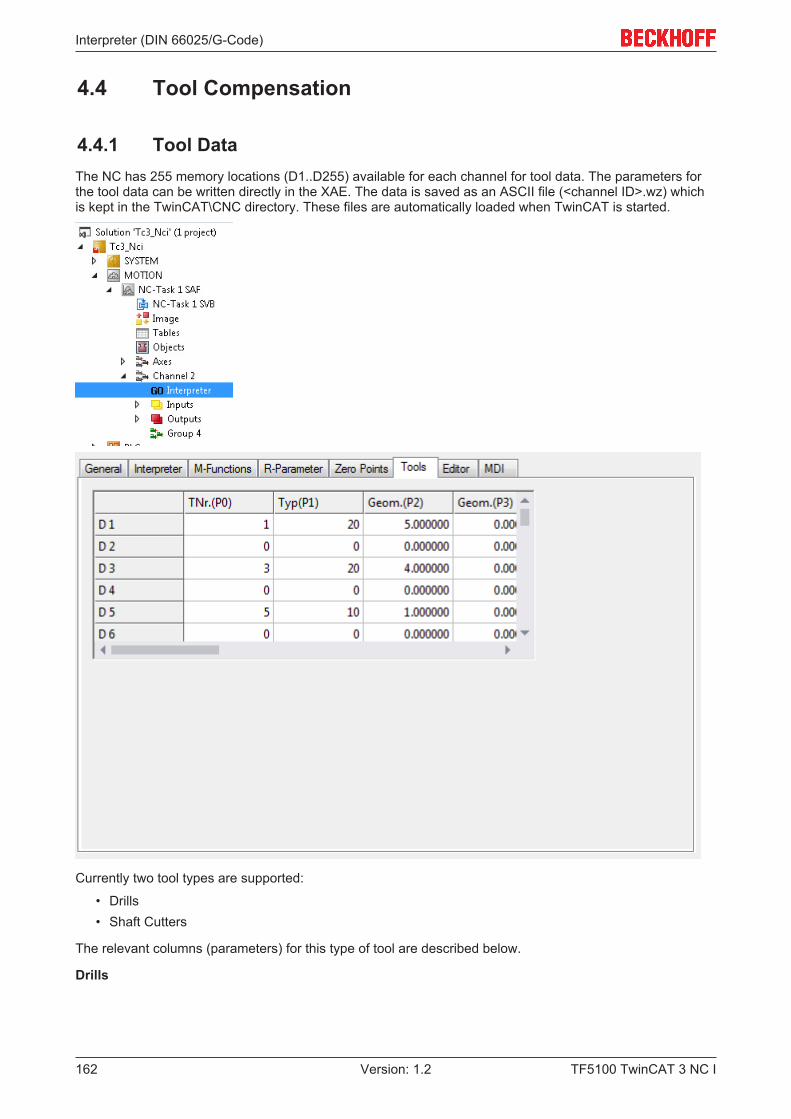
Interpreter (DIN 66025/G-Code)
TF5100 TwinCAT 3 NC I162 Version: 1.2
4.4 Tool Compensation
4.4.1 Tool DataThe NC has 255 memory locations (D1..D255) available for each channel for tool data. The parameters forthe tool data can be written directly in the XAE. The data is saved as an ASCII file (<channel ID>.wz) whichis kept in the TwinCAT\CNC directory. These files are automatically loaded when TwinCAT is started.
Currently two tool types are supported:
• Drills• Shaft Cutters
The relevant columns (parameters) for this type of tool are described below.
Drills
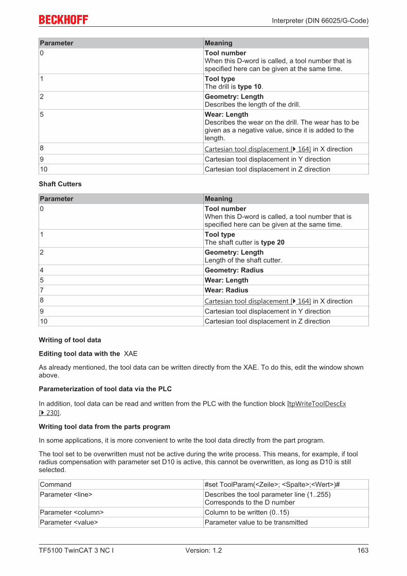
Interpreter (DIN 66025/G-Code)
TF5100 TwinCAT 3 NC I 163Version: 1.2
Parameter Meaning0 Tool number
When this D-word is called, a tool number that isspecified here can be given at the same time.
1 Tool typeThe drill is type 10.
2 Geometry: LengthDescribes the length of the drill.
5 Wear: LengthDescribes the wear on the drill. The wear has to begiven as a negative value, since it is added to thelength.
8 Cartesian tool displacement [} 164] in X direction9 Cartesian tool displacement in Y direction10 Cartesian tool displacement in Z direction
Shaft Cutters
Parameter Meaning0 Tool number
When this D-word is called, a tool number that isspecified here can be given at the same time.
1 Tool typeThe shaft cutter is type 20
2 Geometry: LengthLength of the shaft cutter.
4 Geometry: Radius5 Wear: Length7 Wear: Radius8 Cartesian tool displacement [} 164] in X direction9 Cartesian tool displacement in Y direction10 Cartesian tool displacement in Z direction
Writing of tool data
Editing tool data with the XAE
As already mentioned, the tool data can be written directly from the XAE. To do this, edit the window shownabove.
Parameterization of tool data via the PLC
In addition, tool data can be read and written from the PLC with the function block ItpWriteToolDescEx[} 230].
Writing tool data from the parts program
In some applications, it is more convenient to write the tool data directly from the part program.
The tool set to be overwritten must not be active during the write process. This means, for example, if toolradius compensation with parameter set D10 is active, this cannot be overwritten, as long as D10 is stillselected.
Command #set ToolParam(<Zeile>; <Spalte>;<Wert>)#Parameter <line> Describes the tool parameter line (1..255)
Corresponds to the D numberParameter <column> Column to be written (0..15)Parameter <value> Parameter value to be transmitted
Interpreter (DIN 66025/G-Code)
TF5100 TwinCAT 3 NC I164 Version: 1.2
Sample:N10 G0 X0 Y0 Z0N20 G01 X100 F60000N30 R1=10 R2=4 R3=20.3N40 #set ToolParam(10; 0; 5)# #set ToolParam(10;1;20)#N50 #set ToolParam(R1; R2; R3)#N60 G41 X200 Y D10...
NOTE! No formulas may be transmitted as parameters. Writing of the tool data does not require adecoder stop.
Reading tool data from the parts program
This command can be used to assign tool data to an R-parameter.
Command #get ToolParam(<line>; <column>;<R-Param>)#Parameter <line> Writes to the tool parameter line (1..255); this
corresponds to the D numberParameter <column> Column to be written (0..15)Parameter <R-Param> R-parameter in which the date is entered
Sample:N10 G0 X0 Y0 Z0N20 G01 X100 F60000N30 R1=10 R2=4N40 #get ToolParam(10; 0; R5)# #getToolParam(10;1;R20)#N50 #get ToolParam(R1; R2; R3)#N60 G41 X200 Y D10...
Notes:
NOTE! No formulas may be transmitted as parameters. Reading of the tool data does not require adecoder stop.
4.4.2 Selecting and Deselecting the Length CompensationLength compensation can only be selected when G0 [} 118] or G1 [} 119] are in effect. The working plane[} 111] must be selected to which the length compensation is perpendicular.
The feed direction is specified with P (see working plane and feed direction [} 111]).
To effect the movement corresponding to the length compensation, the axis concerned must at least bementioned.
Sample:N10 G17 G01 X0 Y0 Z0 F6000N20 D1 X10 Y10 ZN30 ...N90 M30
NOTE! Length correction is automatically selected when cutter radius compensation [} 167] isselected.To deselect length correction, D0 has to be programmed. It is again here necessary to atleast mention the axis concerned in order to move to the new position.
4.4.3 Cartesian Tool TranslationCartesian tool displacement refers to an offset between the reference point of the tool carrier and thereference point of the tool itself. In many cases, these reference points have the same location, so that a 0can be entered for the tool displacement.
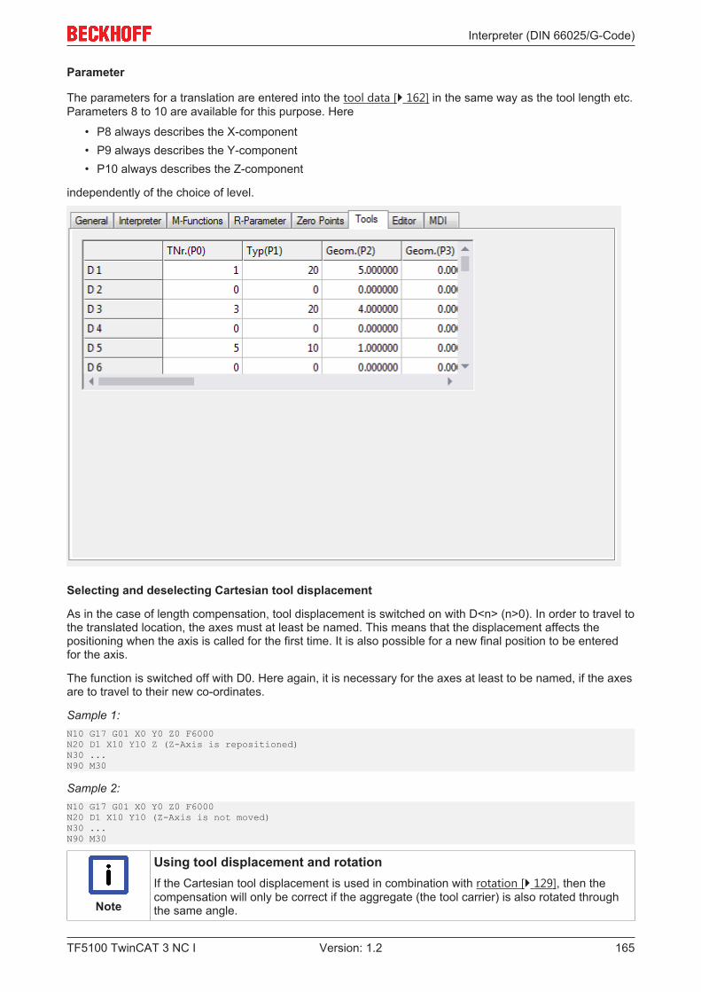
Interpreter (DIN 66025/G-Code)
TF5100 TwinCAT 3 NC I 165Version: 1.2
Parameter
The parameters for a translation are entered into the tool data [} 162] in the same way as the tool length etc.Parameters 8 to 10 are available for this purpose. Here
• P8 always describes the X-component• P9 always describes the Y-component• P10 always describes the Z-component
independently of the choice of level.
Selecting and deselecting Cartesian tool displacement
As in the case of length compensation, tool displacement is switched on with D<n> (n>0). In order to travel tothe translated location, the axes must at least be named. This means that the displacement affects thepositioning when the axis is called for the first time. It is also possible for a new final position to be enteredfor the axis.
The function is switched off with D0. Here again, it is necessary for the axes at least to be named, if the axesare to travel to their new co-ordinates.
Sample 1:N10 G17 G01 X0 Y0 Z0 F6000N20 D1 X10 Y10 Z (Z-Axis is repositioned)N30 ...N90 M30
Sample 2:N10 G17 G01 X0 Y0 Z0 F6000N20 D1 X10 Y10 (Z-Axis is not moved)N30 ...N90 M30
Note
Using tool displacement and rotationIf the Cartesian tool displacement is used in combination with rotation [} 129], then thecompensation will only be correct if the aggregate (the tool carrier) is also rotated throughthe same angle.

Interpreter (DIN 66025/G-Code)
TF5100 TwinCAT 3 NC I166 Version: 1.2
Application sample
It often happens that a processing machine's tool carrier contains a number of tools. The appropriate tool ispneumatically activated according to the kind of machining required. Since, however, the tools are located atdifferent positions, Cartesian tool displacement is required.
Tool parameters
Parameter Value0 0..655351 102 405 08 100.09 0.010 50
Behavior with incremental dimension notation
Default behavior
If a new tool offset (and also length compensation) is selected in incremental dimensions (G91), then thecompensation is applied once the axis is named.
Sample 3:(Tooloffset D1: X10 Y20 Z30)N10 G01 D1 X100 Y0 Z0 F6000N20 G91 (incremental dimension)N30 D2 (Tooloffset D2: X100Y200 Z300)N30 Z10N40 ...
Command DescriptionToolOffsetIncOn The tool displacements and length compensations
are also applied under G91 once the axis is namedToolOffsetIncOff The tool displacement and length compensation are
not applied under G91
Sample 4:(Tooloffset D1: X10 Y20 Z30)N05 ToolOffsetIncOffN10 G01 D1 X100 Y0 Z0 F6000N20 G91 (incremental dimension)N30 D2 (Tooloffset D2: X100Y200 Z300)N30 Z10N40 ...

Interpreter (DIN 66025/G-Code)
TF5100 TwinCAT 3 NC I 167Version: 1.2
In N10 the Tooloffset is applied to all 3 axes. I.e. the axes move in the machine coordinate system (MCS) toX110 Y10 Z30.
In N30 the new Tooloffset of the Z-axis is not applied. This results in MCS X110 Y10 Z40.
See also ZeroShiftIncOn/Off [} 124]
4.4.4 Cutter Radius Compensation
4.4.4.1 Miller/Cutter Radius Compensation Off
Miller/Cutter Radius Compensation Off
Command G40Cancellation G41 [} 167] or G42 [} 168]
The G40 function switches the miller/cutter radius compensation off. The length radius compensation [} 164]will still remain active until it is switched off with D0. Between G40 and end of program it is madatory toprogram at least one geometry element.
4.4.4.2 Miller/cutter radius compensation left
Miller/cutter radius compensation left
Command G41Cancellation G40 [} 167]
The function G41 switches on the miller/cutter radius compensation. The tool is located to the left of theworkpiece in the direction of movement.
As has already been seen for the length compensation [} 164], the cutter radius compensation can only beactivated when G0 [} 118] or G1 [} 119] is in effect. The axes of the plane must be driven when the cutterradius compensation is selected.
Sample:N10 G17 G01 X0 Y0 Z0 F6000 N20 G41 X10 Y20 Z D1 N30 X30 N40 G40 X10 Y10 ZN50 M30
Note
Cutter radius compensation does not apply to full circlesThe cutter radius compensation does not support full circles. Full circles have to be splitinto semicircles, for sample.
Notes:
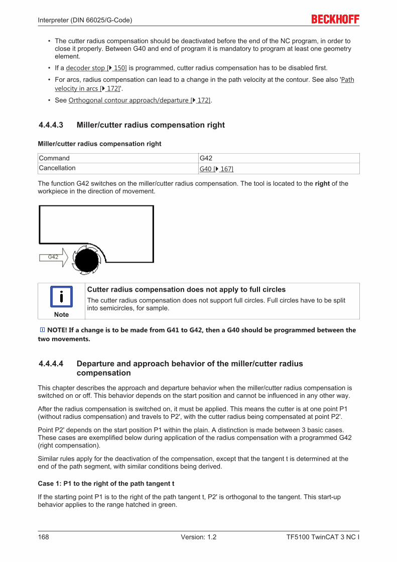
Interpreter (DIN 66025/G-Code)
TF5100 TwinCAT 3 NC I168 Version: 1.2
• The cutter radius compensation should be deactivated before the end of the NC program, in order toclose it properly. Between G40 and end of program it is mandatory to program at least one geometryelement.
• If a decoder stop [} 150] is programmed, cutter radius compensation has to be disabled first.
• For arcs, radius compensation can lead to a change in the path velocity at the contour. See also 'Pathvelocity in arcs [} 172]'.
• See Orthogonal contour approach/departure [} 172].
4.4.4.3 Miller/cutter radius compensation right
Miller/cutter radius compensation right
Command G42Cancellation G40 [} 167]
The function G42 switches on the miller/cutter radius compensation. The tool is located to the right of theworkpiece in the direction of movement.
Note
Cutter radius compensation does not apply to full circlesThe cutter radius compensation does not support full circles. Full circles have to be splitinto semicircles, for sample.
NOTE! If a change is to be made from G41 to G42, then a G40 should be programmed between thetwo movements.
4.4.4.4 Departure and approach behavior of the miller/cutter radiuscompensation
This chapter describes the approach and departure behavior when the miller/cutter radius compensation isswitched on or off. This behavior depends on the start position and cannot be influenced in any other way.
After the radius compensation is switched on, it must be applied. This means the cutter is at one point P1(without radius compensation) and travels to P2', with the cutter radius being compensated at point P2'.
Point P2' depends on the start position P1 within the plain. A distinction is made between 3 basic cases.These cases are exemplified below during application of the radius compensation with a programmed G42(right compensation).
Similar rules apply for the deactivation of the compensation, except that the tangent t is determined at theend of the path segment, with similar conditions being derived.
Case 1: P1 to the right of the path tangent t
If the starting point P1 is to the right of the path tangent t, P2' is orthogonal to the tangent. This start-upbehavior applies to the range hatched in green.
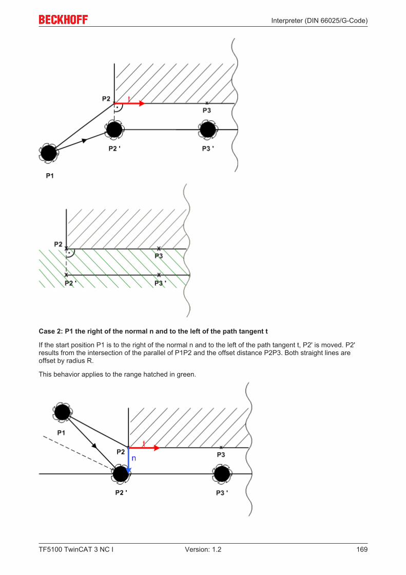
Interpreter (DIN 66025/G-Code)
TF5100 TwinCAT 3 NC I 169Version: 1.2
Case 2: P1 the right of the normal n and to the left of the path tangent t
If the start position P1 is to the right of the normal n and to the left of the path tangent t, P2' is moved. P2'results from the intersection of the parallel of P1P2 and the offset distance P2P3. Both straight lines areoffset by radius R.
This behavior applies to the range hatched in green.
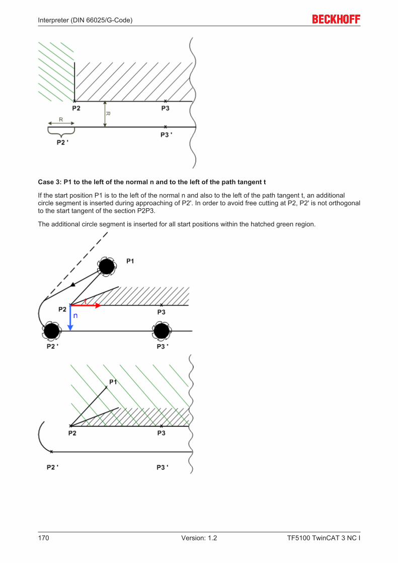
Interpreter (DIN 66025/G-Code)
TF5100 TwinCAT 3 NC I170 Version: 1.2
Case 3: P1 to the left of the normal n and to the left of the path tangent t
If the start position P1 is to the left of the normal n and also to the left of the path tangent t, an additionalcircle segment is inserted during approaching of P2'. In order to avoid free cutting at P2, P2' is not orthogonalto the start tangent of the section P2P3.
The additional circle segment is inserted for all start positions within the hatched green region.
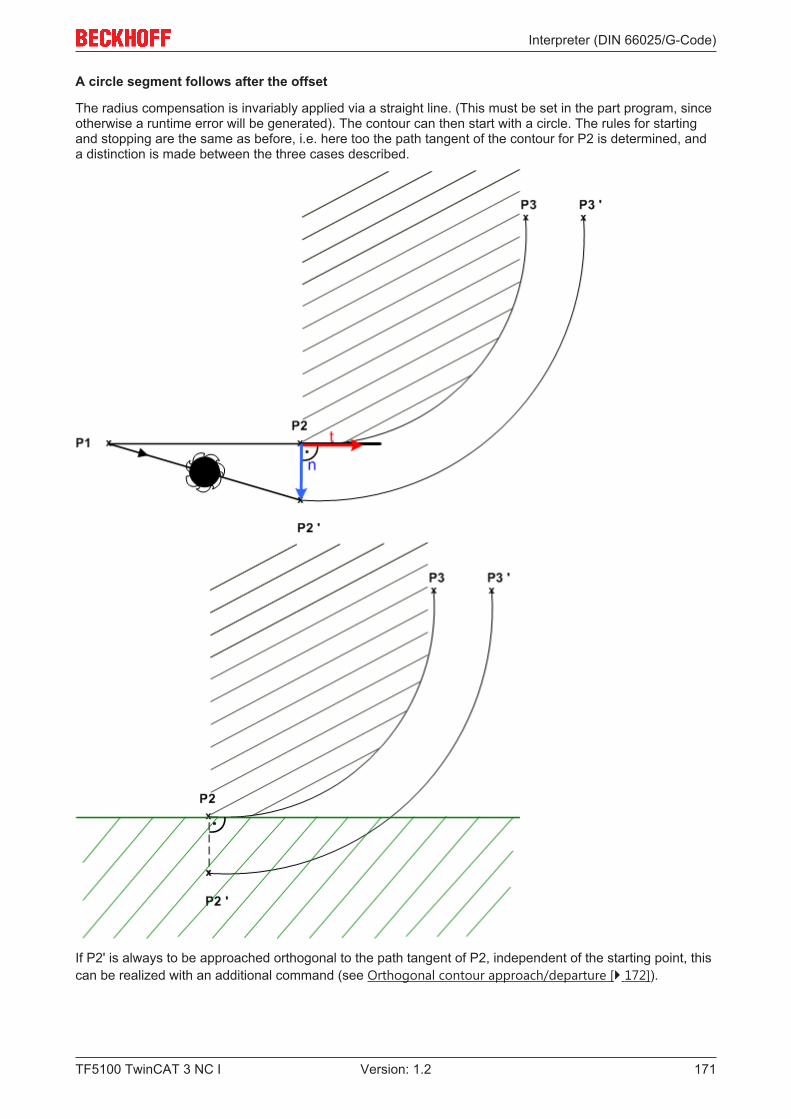
Interpreter (DIN 66025/G-Code)
TF5100 TwinCAT 3 NC I 171Version: 1.2
A circle segment follows after the offset
The radius compensation is invariably applied via a straight line. (This must be set in the part program, sinceotherwise a runtime error will be generated). The contour can then start with a circle. The rules for startingand stopping are the same as before, i.e. here too the path tangent of the contour for P2 is determined, anda distinction is made between the three cases described.
If P2' is always to be approached orthogonal to the path tangent of P2, independent of the starting point, thiscan be realized with an additional command (see Orthogonal contour approach/departure [} 172]).
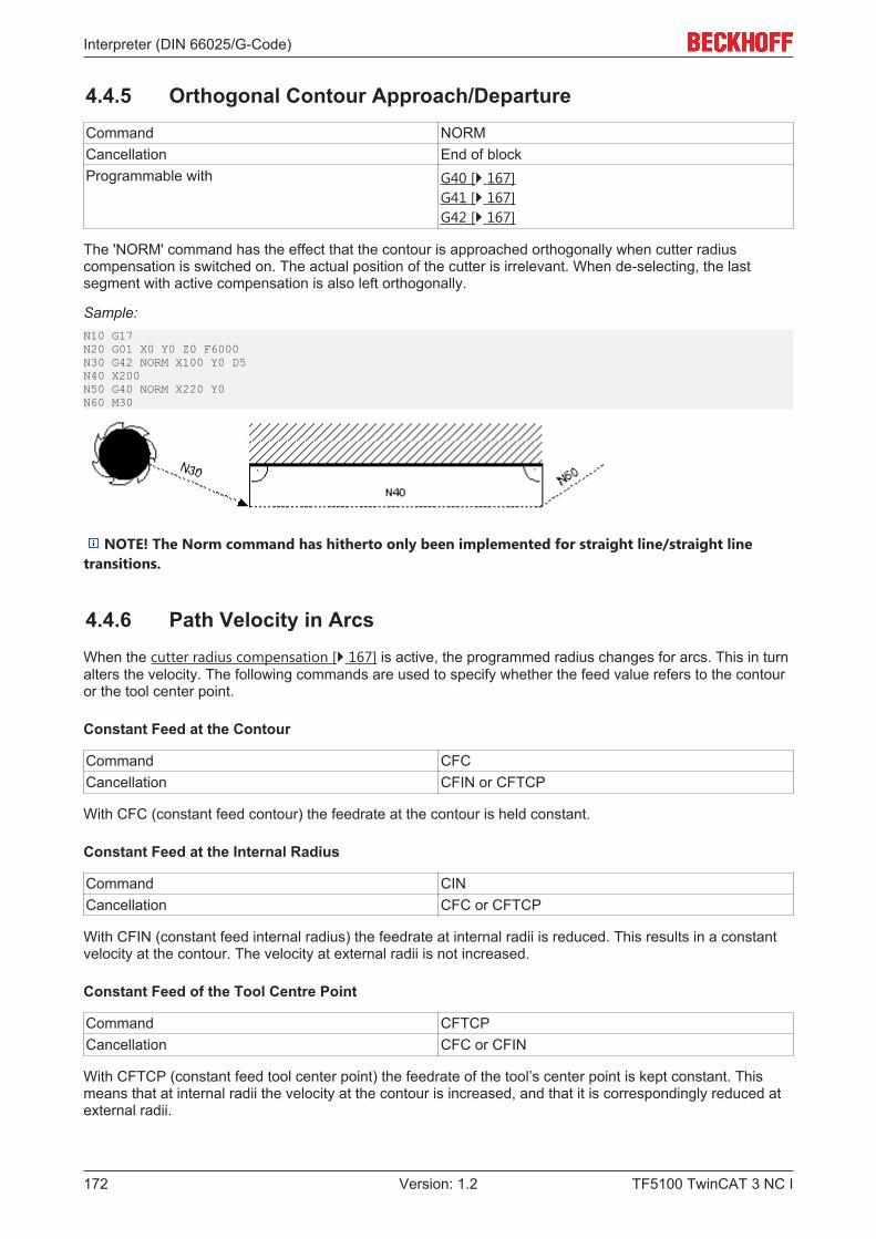
Interpreter (DIN 66025/G-Code)
TF5100 TwinCAT 3 NC I172 Version: 1.2
4.4.5 Orthogonal Contour Approach/DepartureCommand NORMCancellation End of blockProgrammable with G40 [} 167]
G41 [} 167] G42 [} 167]
The 'NORM' command has the effect that the contour is approached orthogonally when cutter radiuscompensation is switched on. The actual position of the cutter is irrelevant. When de-selecting, the lastsegment with active compensation is also left orthogonally.
Sample:N10 G17 N20 G01 X0 Y0 Z0 F6000N30 G42 NORM X100 Y0 D5N40 X200 N50 G40 NORM X220 Y0N60 M30
NOTE! The Norm command has hitherto only been implemented for straight line/straight linetransitions.
4.4.6 Path Velocity in ArcsWhen the cutter radius compensation [} 167] is active, the programmed radius changes for arcs. This in turnalters the velocity. The following commands are used to specify whether the feed value refers to the contouror the tool center point.
Constant Feed at the Contour
Command CFCCancellation CFIN or CFTCP
With CFC (constant feed contour) the feedrate at the contour is held constant.
Constant Feed at the Internal Radius
Command CINCancellation CFC or CFTCP
With CFIN (constant feed internal radius) the feedrate at internal radii is reduced. This results in a constantvelocity at the contour. The velocity at external radii is not increased.
Constant Feed of the Tool Centre Point
Command CFTCPCancellation CFC or CFIN
With CFTCP (constant feed tool center point) the feedrate of the tool’s center point is kept constant. Thismeans that at internal radii the velocity at the contour is increased, and that it is correspondingly reduced atexternal radii.
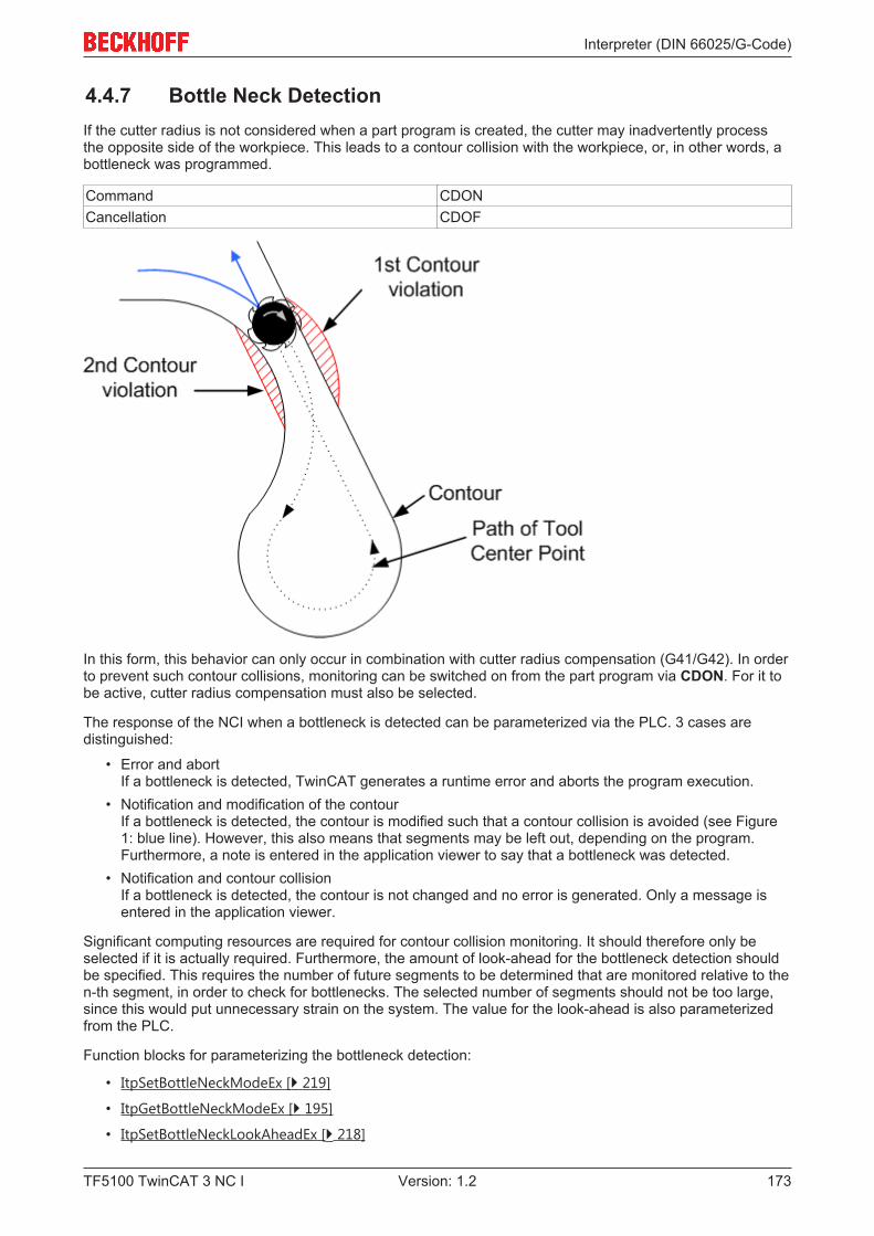
Interpreter (DIN 66025/G-Code)
TF5100 TwinCAT 3 NC I 173Version: 1.2
4.4.7 Bottle Neck DetectionIf the cutter radius is not considered when a part program is created, the cutter may inadvertently processthe opposite side of the workpiece. This leads to a contour collision with the workpiece, or, in other words, abottleneck was programmed.
Command CDONCancellation CDOF
In this form, this behavior can only occur in combination with cutter radius compensation (G41/G42). In orderto prevent such contour collisions, monitoring can be switched on from the part program via CDON. For it tobe active, cutter radius compensation must also be selected.
The response of the NCI when a bottleneck is detected can be parameterized via the PLC. 3 cases aredistinguished:
• Error and abortIf a bottleneck is detected, TwinCAT generates a runtime error and aborts the program execution.
• Notification and modification of the contourIf a bottleneck is detected, the contour is modified such that a contour collision is avoided (see Figure1: blue line). However, this also means that segments may be left out, depending on the program.Furthermore, a note is entered in the application viewer to say that a bottleneck was detected.
• Notification and contour collisionIf a bottleneck is detected, the contour is not changed and no error is generated. Only a message isentered in the application viewer.
Significant computing resources are required for contour collision monitoring. It should therefore only beselected if it is actually required. Furthermore, the amount of look-ahead for the bottleneck detection shouldbe specified. This requires the number of future segments to be determined that are monitored relative to then-th segment, in order to check for bottlenecks. The selected number of segments should not be too large,since this would put unnecessary strain on the system. The value for the look-ahead is also parameterizedfrom the PLC.
Function blocks for parameterizing the bottleneck detection:
• ItpSetBottleNeckModeEx [} 219]
• ItpGetBottleNeckModeEx [} 195]
• ItpSetBottleNeckLookAheadEx [} 218]
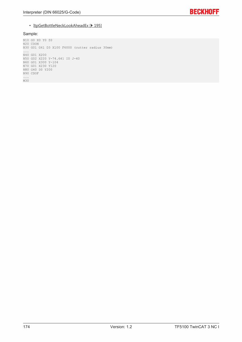
Interpreter (DIN 66025/G-Code)
TF5100 TwinCAT 3 NC I174 Version: 1.2
• ItpGetBottleNeckLookAheadEx [} 195]
Sample:N10 G0 X0 Y0 Z0N20 CDONN30 G01 G41 D3 X100 F6000 (cutter radius 30mm)...N40 G01 X200N50 G02 X220 Y-74.641 I0 J-40N60 G01 X300 Y-104N70 G01 X230 Y120N80 G40 D0 Y200N90 CDOF...M30
Interpreter (DIN 66025/G-Code)
TF5100 TwinCAT 3 NC I 175Version: 1.2
4.5 Command overview
4.5.1 General command overview
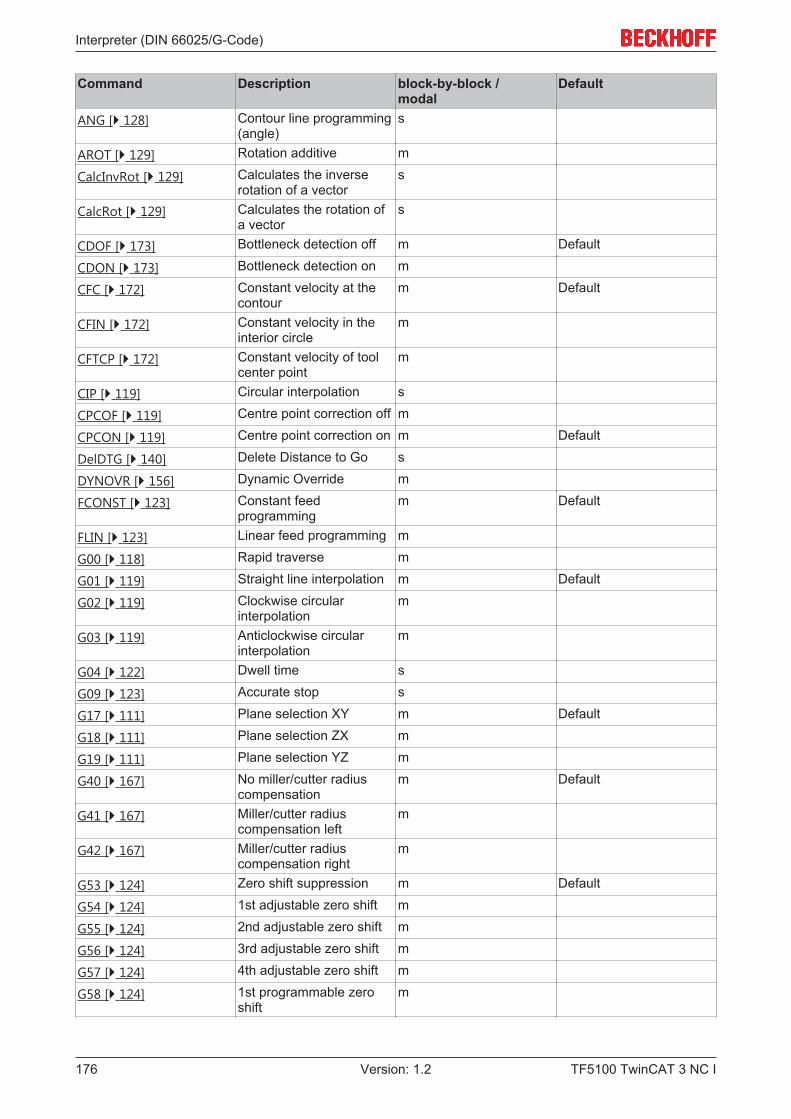
Interpreter (DIN 66025/G-Code)
TF5100 TwinCAT 3 NC I176 Version: 1.2
Command Description block-by-block / modal
Default
ANG [} 128] Contour line programming(angle)
s
AROT [} 129] Rotation additive m
CalcInvRot [} 129] Calculates the inverserotation of a vector
s
CalcRot [} 129] Calculates the rotation ofa vector
s
CDOF [} 173] Bottleneck detection off m Default
CDON [} 173] Bottleneck detection on m
CFC [} 172] Constant velocity at thecontour
m Default
CFIN [} 172] Constant velocity in theinterior circle
m
CFTCP [} 172] Constant velocity of toolcenter point
m
CIP [} 119] Circular interpolation s
CPCOF [} 119] Centre point correction off m
CPCON [} 119] Centre point correction on m Default
DelDTG [} 140] Delete Distance to Go s
DYNOVR [} 156] Dynamic Override m
FCONST [} 123] Constant feedprogramming
m Default
FLIN [} 123] Linear feed programming m
G00 [} 118] Rapid traverse m
G01 [} 119] Straight line interpolation m Default
G02 [} 119] Clockwise circularinterpolation
m
G03 [} 119] Anticlockwise circularinterpolation
m
G04 [} 122] Dwell time s
G09 [} 123] Accurate stop s
G17 [} 111] Plane selection XY m Default
G18 [} 111] Plane selection ZX m
G19 [} 111] Plane selection YZ m
G40 [} 167] No miller/cutter radiuscompensation
m Default
G41 [} 167] Miller/cutter radiuscompensation left
m
G42 [} 167] Miller/cutter radiuscompensation right
m
G53 [} 124] Zero shift suppression m Default
G54 [} 124] 1st adjustable zero shift m
G55 [} 124] 2nd adjustable zero shift m
G56 [} 124] 3rd adjustable zero shift m
G57 [} 124] 4th adjustable zero shift m
G58 [} 124] 1st programmable zeroshift
m
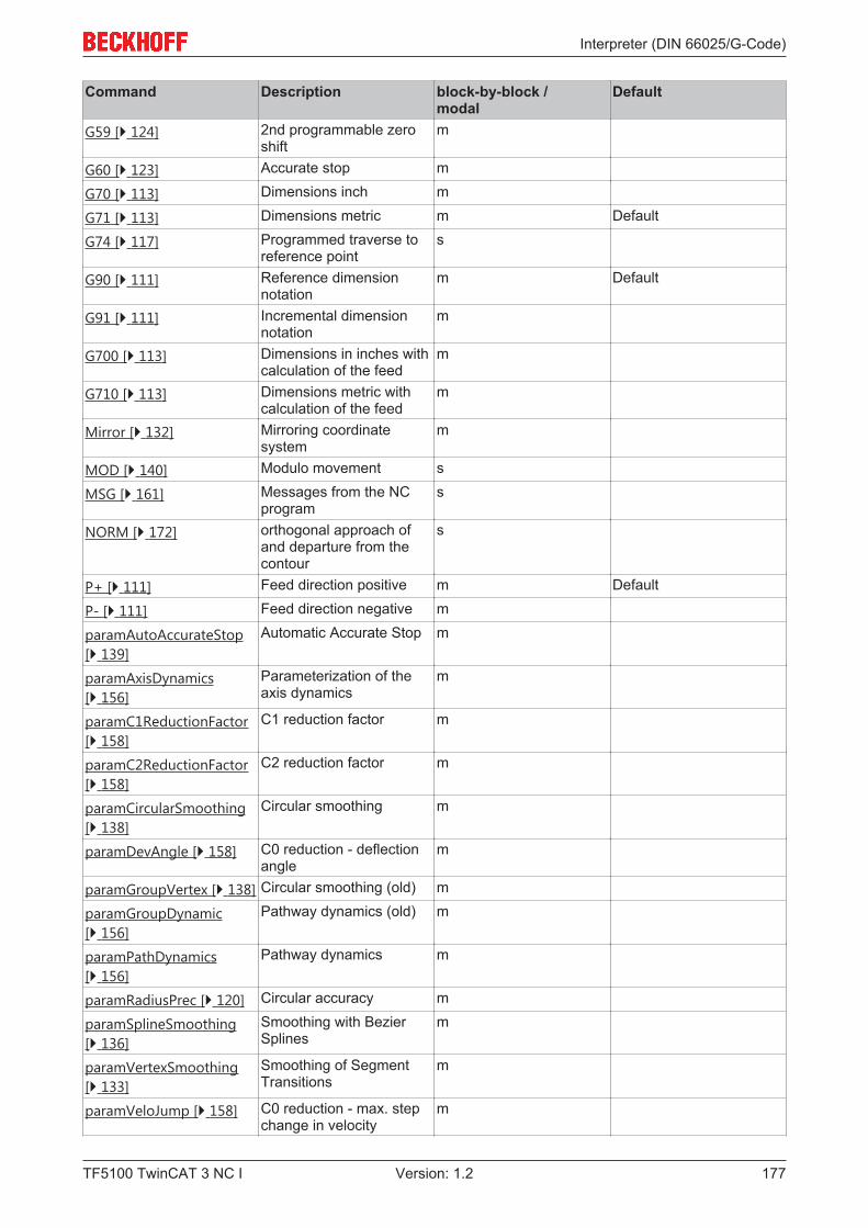
Interpreter (DIN 66025/G-Code)
TF5100 TwinCAT 3 NC I 177Version: 1.2
Command Description block-by-block / modal
Default
G59 [} 124] 2nd programmable zeroshift
m
G60 [} 123] Accurate stop m
G70 [} 113] Dimensions inch m
G71 [} 113] Dimensions metric m Default
G74 [} 117] Programmed traverse toreference point
s
G90 [} 111] Reference dimensionnotation
m Default
G91 [} 111] Incremental dimensionnotation
m
G700 [} 113] Dimensions in inches withcalculation of the feed
m
G710 [} 113] Dimensions metric withcalculation of the feed
m
Mirror [} 132] Mirroring coordinatesystem
m
MOD [} 140] Modulo movement s
MSG [} 161] Messages from the NCprogram
s
NORM [} 172] orthogonal approach ofand departure from thecontour
s
P+ [} 111] Feed direction positive m Default
P- [} 111] Feed direction negative m
paramAutoAccurateStop[} 139]
Automatic Accurate Stop m
paramAxisDynamics[} 156]
Parameterization of theaxis dynamics
m
paramC1ReductionFactor[} 158]
C1 reduction factor m
paramC2ReductionFactor[} 158]
C2 reduction factor m
paramCircularSmoothing[} 138]
Circular smoothing m
paramDevAngle [} 158] C0 reduction - deflectionangle
m
paramGroupVertex [} 138] Circular smoothing (old) m
paramGroupDynamic[} 156]
Pathway dynamics (old) m
paramPathDynamics[} 156]
Pathway dynamics m
paramRadiusPrec [} 120] Circular accuracy m
paramSplineSmoothing[} 136]
Smoothing with BezierSplines
m
paramVertexSmoothing[} 133]
Smoothing of SegmentTransitions
m
paramVeloJump [} 158] C0 reduction - max. stepchange in velocity
m
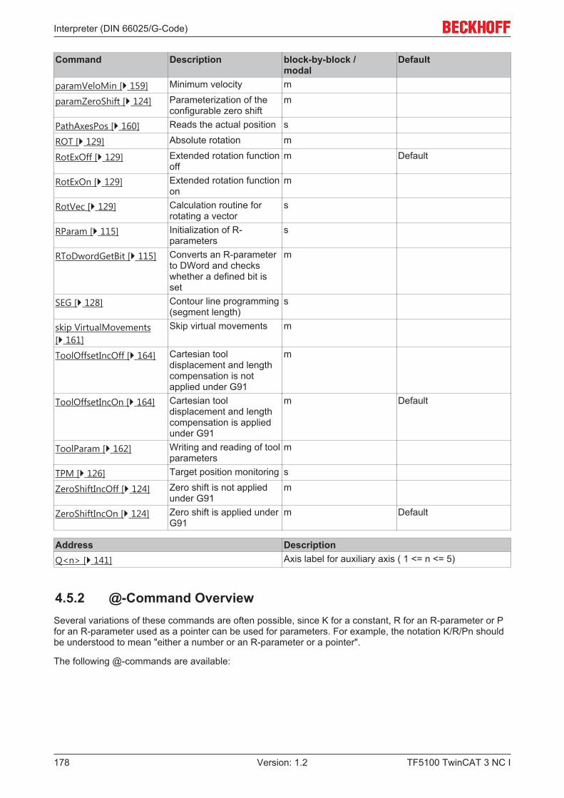
Interpreter (DIN 66025/G-Code)
TF5100 TwinCAT 3 NC I178 Version: 1.2
Command Description block-by-block / modal
Default
paramVeloMin [} 159] Minimum velocity m
paramZeroShift [} 124] Parameterization of theconfigurable zero shift
m
PathAxesPos [} 160] Reads the actual position s
ROT [} 129] Absolute rotation m
RotExOff [} 129] Extended rotation functionoff
m Default
RotExOn [} 129] Extended rotation functionon
m
RotVec [} 129] Calculation routine forrotating a vector
s
RParam [} 115] Initialization of R-parameters
s
RToDwordGetBit [} 115] Converts an R-parameterto DWord and checkswhether a defined bit isset
m
SEG [} 128] Contour line programming(segment length)
s
skip VirtualMovements[} 161]
Skip virtual movements m
ToolOffsetIncOff [} 164] Cartesian tooldisplacement and lengthcompensation is notapplied under G91
m
ToolOffsetIncOn [} 164] Cartesian tooldisplacement and lengthcompensation is appliedunder G91
m Default
ToolParam [} 162] Writing and reading of toolparameters
m
TPM [} 126] Target position monitoring s
ZeroShiftIncOff [} 124] Zero shift is not appliedunder G91
m
ZeroShiftIncOn [} 124] Zero shift is applied underG91
m Default
Address DescriptionQ<n> [} 141] Axis label for auxiliary axis ( 1 <= n <= 5)
4.5.2 @-Command OverviewSeveral variations of these commands are often possible, since K for a constant, R for an R-parameter or Pfor an R-parameter used as a pointer can be used for parameters. For example, the notation K/R/Pn shouldbe understood to mean "either a number or an R-parameter or a pointer".
The following @-commands are available:
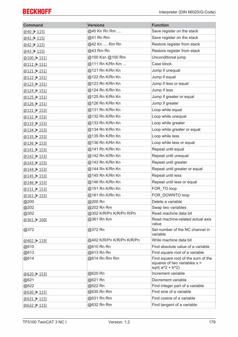
Interpreter (DIN 66025/G-Code)
TF5100 TwinCAT 3 NC I 179Version: 1.2
Command Versions Function@40 [} 115] @40 Kn Rn Rm .... Save register on the stack
@41 [} 115] @41 Rn Rm Save register on the stack
@42 [} 115] @42 Kn .... Rm Rn Restore register from stack
@43 [} 115] @43 Rm Rn Restore register from stack
@100 [} 151] @100 K±n @100 Rm Unconditional jump
@111 [} 151] @111 Rn K/Rn Km ... Case block
@121 [} 151] @121 Rn K/Rn Kn Jump if unequal
@122 [} 151] @122 Rn K/Rn Kn Jump if equal
@123 [} 151] @123 Rn K/Rn Kn Jump if less or equal
@124 [} 151] @124 Rn K/Rn Kn Jump if less
@125 [} 151] @125 Rn K/Rn Kn Jump if greater or equal
@126 [} 151] @126 Rn K/Rn Kn Jump if greater
@131 [} 153] @131 Rn K/Rn Kn Loop while equal
@132 [} 153] @132 Rn K/Rn Kn Loop while unequal
@133 [} 153] @133 Rn K/Rn Kn Loop while greater
@134 [} 153] @134 Rn K/Rn Kn Loop while greater or equal
@135 [} 153] @135 Rn K/Rn Kn Loop while less
@136 [} 153] @136 Rn K/Rn Kn Loop while less or equal
@141 [} 153] @141 Rn K/Rn Kn Repeat until equal
@142 [} 153] @142 Rn K/Rn Kn Repeat until unequal
@143 [} 153] @143 Rn K/Rn Kn Repeat until greater
@144 [} 153] @144 Rn K/Rn Kn Repeat until greater or equal
@145 [} 153] @145 Rn K/Rn Kn Repeat until less
@146 [} 153] @146 Rn K/Rn Kn Repeat until less or equal
@151 [} 153] @151 Rn K/Rn Kn FOR_TO loop
@161 [} 153] @161 Rn K/Rn Kn FOR_DOWNTO loop@200 @200 Rn Delete a variable@202 @202 Rn Rm Swap two variables@302 @302 K/R/Pn K/R/Pn R/Pn Read machine data bit@361 [} 160] @361 Rn Km Read machine-related actual axis
value@372 @372 Rn Set number of the NC channel in
variable@402 [} 119] @402 K/R/Pn K/R/Pn K/R/Pn Write machine data bit@610 @610 Rn Rn Find absolute value of a variable@613 @613 Rn Rn Find square root of a variable@614 @614 Rn Rm Rm Find square root of the sum of the
squares of two variables x =sqrt( a^2 + b^2)
@620 [} 153] @620 Rn Increment variable@621 @621 Rn Decrement variable@622 @622 Rn Find integer part of a variable@630 [} 115] @630 Rn Rm Find sine of a variable
@631 [} 115] @631 Rn Rm Find cosine of a variable
@632 [} 115] @632 Rn Rm Find tangent of a variable
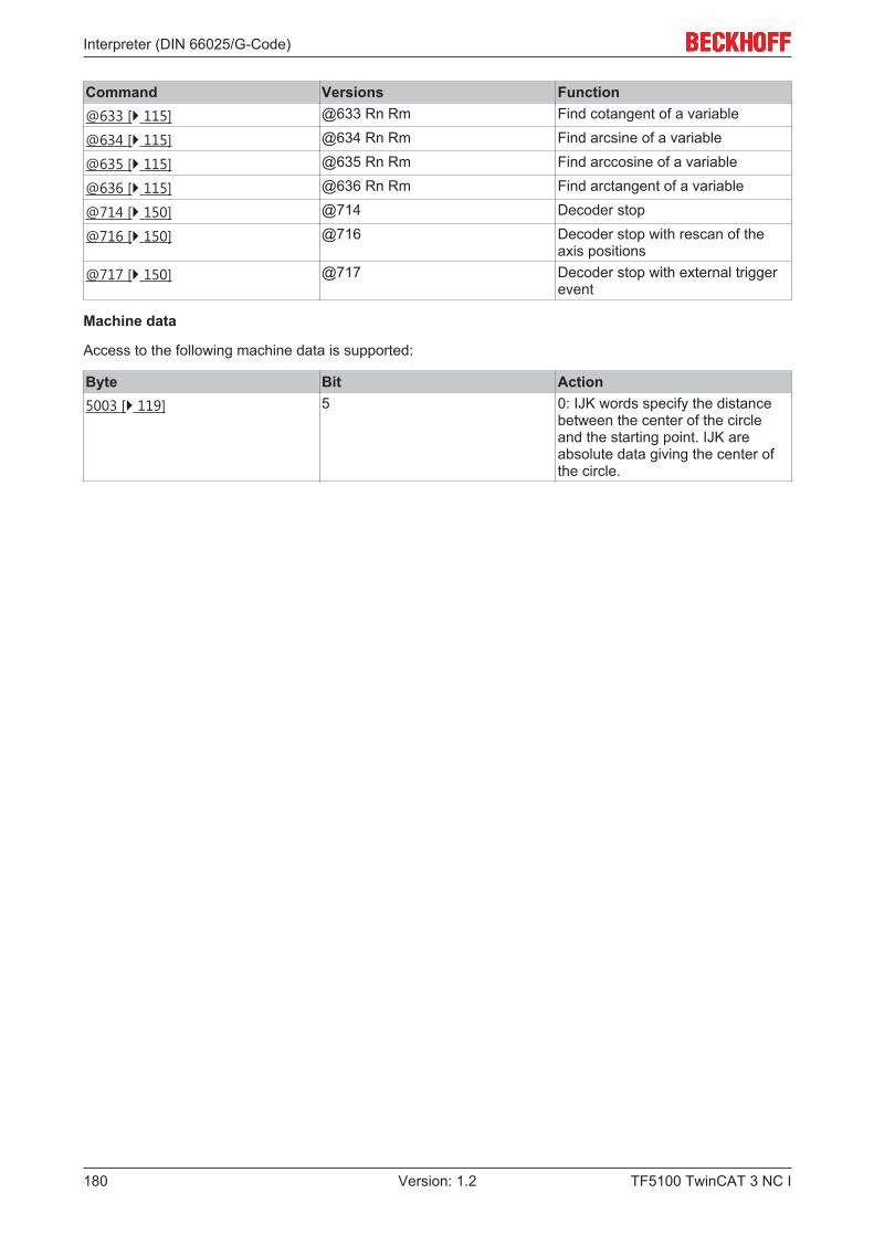
Interpreter (DIN 66025/G-Code)
TF5100 TwinCAT 3 NC I180 Version: 1.2
Command Versions Function@633 [} 115] @633 Rn Rm Find cotangent of a variable
@634 [} 115] @634 Rn Rm Find arcsine of a variable
@635 [} 115] @635 Rn Rm Find arccosine of a variable
@636 [} 115] @636 Rn Rm Find arctangent of a variable
@714 [} 150] @714 Decoder stop
@716 [} 150] @716 Decoder stop with rescan of theaxis positions
@717 [} 150] @717 Decoder stop with external triggerevent
Machine data
Access to the following machine data is supported:
Byte Bit Action5003 [} 119] 5 0: IJK words specify the distance
between the center of the circleand the starting point. IJK areabsolute data giving the center ofthe circle.
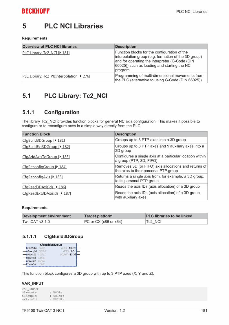
PLC NCI Libraries
TF5100 TwinCAT 3 NC I 181Version: 1.2
5 PLC NCI LibrariesRequirements
Overview of PLC NCI libraries DescriptionPLC Library: Tc2_NCI [} 181] Function blocks for the configuration of the
interpolation group (e.g. formation of the 3D group)and for operating the interpreter (G-Code (DIN66025)) such as loading and starting the NCprogram.
PLC Library: Tc2_PlcInterpolation [} 276] Programming of multi-dimensional movements fromthe PLC (alternative to using G-Code (DIN 66025))
5.1 PLC Library: Tc2_NCI
5.1.1 ConfigurationThe library Tc2_NCI provides function blocks for general NC axis configuration. This makes it possible toconfigure or to reconfigure axes in a simple way directly from the PLC.
Function Block DescriptionCfgBuild3DGroup [} 181] Groups up to 3 PTP axes into a 3D group
CfgBuildExt3DGroup [} 182] Groups up to 3 PTP axes and 5 auxiliary axes into a3D group
CfgAddAxisToGroup [} 183] Configures a single axis at a particular location withina group (PTP, 3D, FIFO)
CfgReconfigGroup [} 184] Removes 3D (or FIFO) axis allocations and returns ofthe axes to their personal PTP group
CfgReconfigAxis [} 185] Returns a single axis from, for example, a 3D group,to its personal PTP group
CfgRead3DAxisIds [} 186] Reads the axis IDs (axis allocation) of a 3D group
CfgReadExt3DAxisIds [} 187] Reads the axis IDs (axis allocation) of a 3D groupwith auxiliary axes
Requirements
Development environment Target platform PLC libraries to be linkedTwinCAT v3.1.0 PC or CX (x86 or x64) Tc2_NCI
5.1.1.1 CfgBuild3DGroup
This function block configures a 3D group with up to 3 PTP axes (X, Y and Z).
VAR_INPUTVAR_INPUTbExecute : BOOL;nGroupId : UDINT;nXAxisId : UDINT;
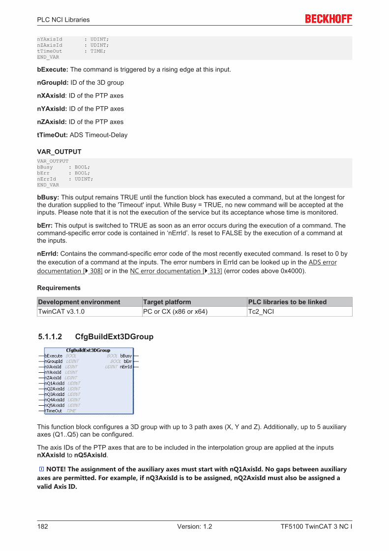
PLC NCI Libraries
TF5100 TwinCAT 3 NC I182 Version: 1.2
nYAxisId : UDINT;nZAxisId : UDINT;tTimeOut : TIME;END_VAR
bExecute: The command is triggered by a rising edge at this input.
nGroupId: ID of the 3D group
nXAxisId: ID of the PTP axes
nYAxisId: ID of the PTP axes
nZAxisId: ID of the PTP axes
tTimeOut: ADS Timeout-Delay
VAR_OUTPUTVAR_OUTPUTbBusy : BOOL;bErr : BOOL;nErrId : UDINT;END_VAR
bBusy: This output remains TRUE until the function block has executed a command, but at the longest forthe duration supplied to the 'Timeout' input. While Busy = TRUE, no new command will be accepted at theinputs. Please note that it is not the execution of the service but its acceptance whose time is monitored.
bErr: This output is switched to TRUE as soon as an error occurs during the execution of a command. Thecommand-specific error code is contained in ‘nErrId’. Is reset to FALSE by the execution of a command atthe inputs.
nErrId: Contains the command-specific error code of the most recently executed command. Is reset to 0 bythe execution of a command at the inputs. The error numbers in ErrId can be looked up in the ADS errordocumentation [} 308] or in the NC error documentation [} 313] (error codes above 0x4000).
Requirements
Development environment Target platform PLC libraries to be linkedTwinCAT v3.1.0 PC or CX (x86 or x64) Tc2_NCI
5.1.1.2 CfgBuildExt3DGroup
This function block configures a 3D group with up to 3 path axes (X, Y and Z). Additionally, up to 5 auxiliaryaxes (Q1..Q5) can be configured.
The axis IDs of the PTP axes that are to be included in the interpolation group are applied at the inputsnXAxisId to nQ5AxisId.
NOTE! The assignment of the auxiliary axes must start with nQ1AxisId. No gaps between auxiliaryaxes are permitted. For example, if nQ3AxisId is to be assigned, nQ2AxisId must also be assigned avalid Axis ID.
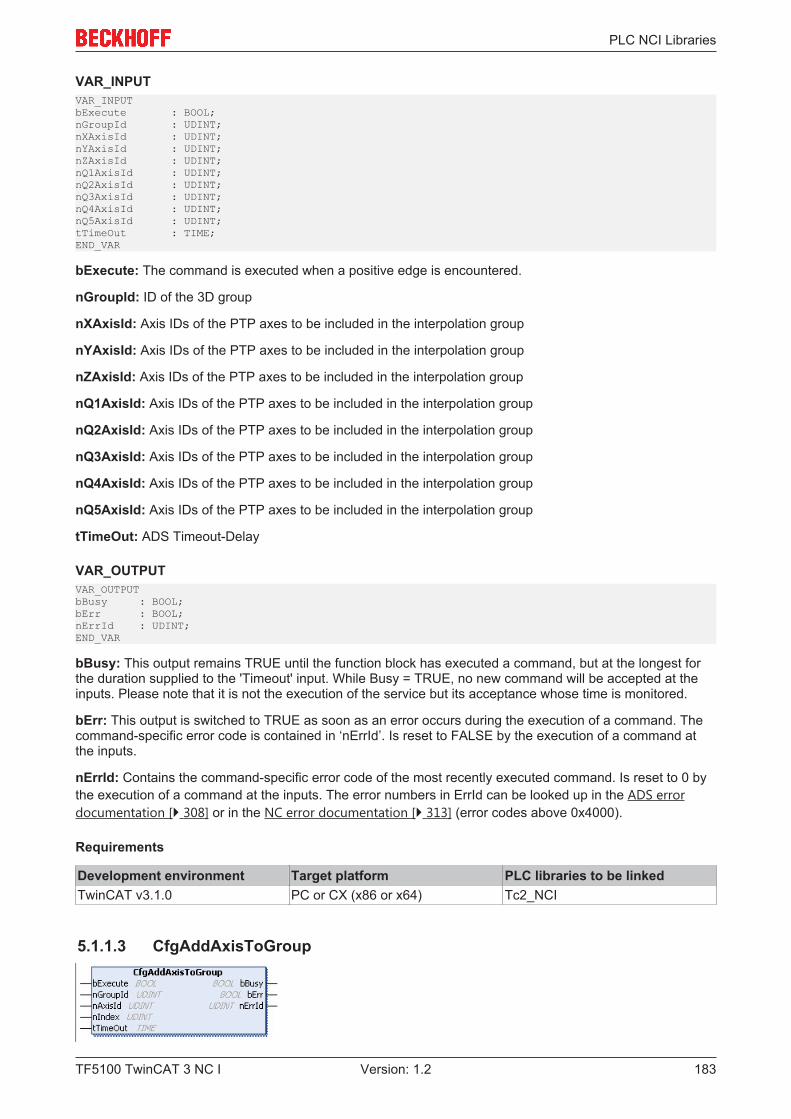
PLC NCI Libraries
TF5100 TwinCAT 3 NC I 183Version: 1.2
VAR_INPUTVAR_INPUTbExecute : BOOL;nGroupId : UDINT;nXAxisId : UDINT;nYAxisId : UDINT;nZAxisId : UDINT;nQ1AxisId : UDINT;nQ2AxisId : UDINT;nQ3AxisId : UDINT;nQ4AxisId : UDINT;nQ5AxisId : UDINT;tTimeOut : TIME;END_VAR
bExecute: The command is executed when a positive edge is encountered.
nGroupId: ID of the 3D group
nXAxisId: Axis IDs of the PTP axes to be included in the interpolation group
nYAxisId: Axis IDs of the PTP axes to be included in the interpolation group
nZAxisId: Axis IDs of the PTP axes to be included in the interpolation group
nQ1AxisId: Axis IDs of the PTP axes to be included in the interpolation group
nQ2AxisId: Axis IDs of the PTP axes to be included in the interpolation group
nQ3AxisId: Axis IDs of the PTP axes to be included in the interpolation group
nQ4AxisId: Axis IDs of the PTP axes to be included in the interpolation group
nQ5AxisId: Axis IDs of the PTP axes to be included in the interpolation group
tTimeOut: ADS Timeout-Delay
VAR_OUTPUTVAR_OUTPUTbBusy : BOOL;bErr : BOOL;nErrId : UDINT;END_VAR
bBusy: This output remains TRUE until the function block has executed a command, but at the longest forthe duration supplied to the 'Timeout' input. While Busy = TRUE, no new command will be accepted at theinputs. Please note that it is not the execution of the service but its acceptance whose time is monitored.
bErr: This output is switched to TRUE as soon as an error occurs during the execution of a command. Thecommand-specific error code is contained in ‘nErrId’. Is reset to FALSE by the execution of a command atthe inputs.
nErrId: Contains the command-specific error code of the most recently executed command. Is reset to 0 bythe execution of a command at the inputs. The error numbers in ErrId can be looked up in the ADS errordocumentation [} 308] or in the NC error documentation [} 313] (error codes above 0x4000).
Requirements
Development environment Target platform PLC libraries to be linkedTwinCAT v3.1.0 PC or CX (x86 or x64) Tc2_NCI
5.1.1.3 CfgAddAxisToGroup
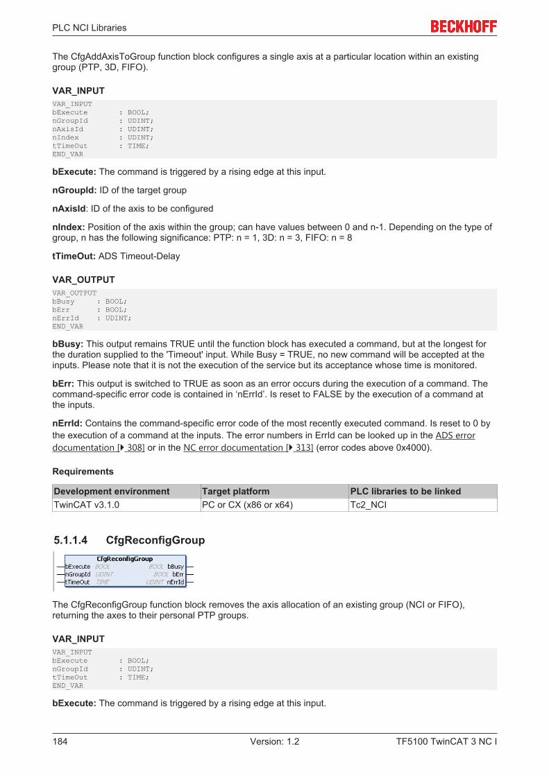
PLC NCI Libraries
TF5100 TwinCAT 3 NC I184 Version: 1.2
The CfgAddAxisToGroup function block configures a single axis at a particular location within an existinggroup (PTP, 3D, FIFO).
VAR_INPUTVAR_INPUTbExecute : BOOL;nGroupId : UDINT;nAxisId : UDINT;nIndex : UDINT;tTimeOut : TIME;END_VAR
bExecute: The command is triggered by a rising edge at this input.
nGroupId: ID of the target group
nAxisId: ID of the axis to be configured
nIndex: Position of the axis within the group; can have values between 0 and n-1. Depending on the type ofgroup, n has the following significance: PTP: n = 1, 3D: n = 3, FIFO: n = 8
tTimeOut: ADS Timeout-Delay
VAR_OUTPUTVAR_OUTPUTbBusy : BOOL;bErr : BOOL;nErrId : UDINT;END_VAR
bBusy: This output remains TRUE until the function block has executed a command, but at the longest forthe duration supplied to the 'Timeout' input. While Busy = TRUE, no new command will be accepted at theinputs. Please note that it is not the execution of the service but its acceptance whose time is monitored.
bErr: This output is switched to TRUE as soon as an error occurs during the execution of a command. Thecommand-specific error code is contained in ‘nErrId’. Is reset to FALSE by the execution of a command atthe inputs.
nErrId: Contains the command-specific error code of the most recently executed command. Is reset to 0 bythe execution of a command at the inputs. The error numbers in ErrId can be looked up in the ADS errordocumentation [} 308] or in the NC error documentation [} 313] (error codes above 0x4000).
Requirements
Development environment Target platform PLC libraries to be linkedTwinCAT v3.1.0 PC or CX (x86 or x64) Tc2_NCI
5.1.1.4 CfgReconfigGroup
The CfgReconfigGroup function block removes the axis allocation of an existing group (NCI or FIFO),returning the axes to their personal PTP groups.
VAR_INPUTVAR_INPUTbExecute : BOOL;nGroupId : UDINT;tTimeOut : TIME;END_VAR
bExecute: The command is triggered by a rising edge at this input.
PLC NCI Libraries
TF5100 TwinCAT 3 NC I 185Version: 1.2
nGroupId: ID of the group to be resolved
tTimeOut: ADS Timeout-Delay
VAR_OUTPUTVAR_OUTPUTbBusy : BOOL;bErr : BOOL;nErrId : UDINT;END_VAR
bBusy: This output remains TRUE until the function block has executed a command, but at the longest forthe duration supplied to the 'Timeout' input. While Busy = TRUE, no new command will be accepted at theinputs. Please note that it is not the execution of the service but its acceptance whose time is monitored.
bErr: This output is switched to TRUE as soon as an error occurs during the execution of a command. Thecommand-specific error code is contained in ‘nErrId’. Is reset to FALSE by the execution of a command atthe inputs.
nErrId: Contains the command-specific error code of the most recently executed command. Is reset to 0 bythe execution of a command at the inputs. The error numbers in ErrId can be looked up in the ADS errordocumentation [} 308] or in the NC error documentation [} 313] (error codes above 0x4000).
Requirements
Development environment Target platform PLC libraries to be linkedTwinCAT v3.1.0 PC or CX (x86 or x64) Tc2_NCI
5.1.1.5 CfgReconfigAxis
The CfgReconfigAxis function block returns a single axis from, for example, a 3D group, to its personal PTPgroup.
InterfaceVAR_INPUTbExecute : BOOL;nAxisId : UDINT;tTimeOut : TIME;END_VAR
bExecute: The command is triggered by a rising edge at this input.
nAxisId: ID of the axis to be returned
tTimeOut: ADS Timeout-Delay
VAR_OUTPUTVAR_OUTPUTbBusy : BOOL;bErr : BOOL;nErrId : UDINT;END_VAR
bBusy: This output remains TRUE until the function block has executed a command, but at the longest forthe duration supplied to the 'Timeout' input. While Busy = TRUE, no new command will be accepted at theinputs. Please note that it is not the execution of the service but its acceptance whose time is monitored.
bErr: This output is switched to TRUE as soon as an error occurs during the execution of a command. Thecommand-specific error code is contained in ‘nErrId’. Is reset to FALSE by the execution of a command atthe inputs.
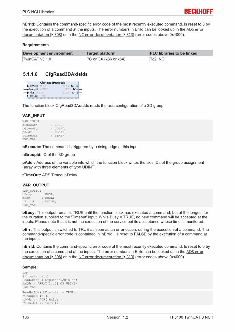
PLC NCI Libraries
TF5100 TwinCAT 3 NC I186 Version: 1.2
nErrId: Contains the command-specific error code of the most recently executed command. Is reset to 0 bythe execution of a command at the inputs. The error numbers in ErrId can be looked up in the ADS errordocumentation [} 308] or in the NC error documentation [} 313] (error codes above 0x4000).
Requirements
Development environment Target platform PLC libraries to be linkedTwinCAT v3.1.0 PC or CX (x86 or x64) Tc2_NCI
5.1.1.6 CfgRead3DAxisIds
The function block CfgRead3DAxisIds reads the axis configuration of a 3D group.
VAR_INPUTVAR_INPUTbExecute : BOOL;nGroupId : UDINT;pAddr : PVOID;tTimeOut : TIME;END_VAR
bExecute: The command is triggered by a rising edge at this input.
nGroupId: ID of the 3D group
pAddr: Address of the variable into which the function block writes the axis IDs of the group assignment(array with three elements of type UDINT)
tTimeOut: ADS Timeout-Delay
VAR_OUTPUTVAR_OUTPUTbBusy : BOOL;bErr : BOOL;nErrId : UDINT;END_VAR
bBusy: This output remains TRUE until the function block has executed a command, but at the longest forthe duration supplied to the 'Timeout' input. While Busy = TRUE, no new command will be accepted at theinputs. Please note that it is not the execution of the service but its acceptance whose time is monitored.
bErr: This output is switched to TRUE as soon as an error occurs during the execution of a command. Thecommand-specific error code is contained in ‘nErrId’. Is reset to FALSE by the execution of a command atthe inputs.
nErrId: Contains the command-specific error code of the most recently executed command. Is reset to 0 bythe execution of a command at the inputs. The error numbers in ErrId can be looked up in the ADS errordocumentation [} 308] or in the NC error documentation [} 313] (error codes above 0x4000).
Sample:VAR(* instance *)ReadAxIds : CfgRead3DAxisIds;AxIds : ARRAY[1..3] OF UDINT;END_VAR
ReadAxIds( bExecute := TRUE,nGroupId := 4,pAddr := ADR( AxIds ),tTimeOut := T#1s );
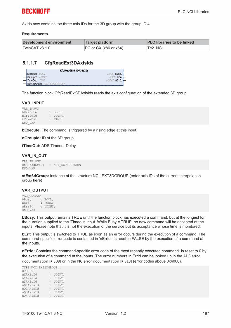
PLC NCI Libraries
TF5100 TwinCAT 3 NC I 187Version: 1.2
AxIds now contains the three axis IDs for the 3D group with the group ID 4.
Requirements
Development environment Target platform PLC libraries to be linkedTwinCAT v3.1.0 PC or CX (x86 or x64) Tc2_NCI
5.1.1.7 CfgReadExt3DAxisIds
The function block CfgReadExt3DAxisIds reads the axis configuration of the extended 3D group.
VAR_INPUTVAR_INPUTbExecute : BOOL;nGroupId : UDINT;tTimeOut : TIME;END_VAR
bExecute: The command is triggered by a rising edge at this input.
nGroupId: ID of the 3D group
tTimeOut: ADS Timeout-Delay
VAR_IN_OUTVAR_IN_OUTstExt3dGroup : NCI_EXT3DGROUP;END_VAR
stExt3dGroup: Instance of the structure NCI_EXT3DGROUP (enter axis IDs of the current interpolationgroup here)
VAR_OUTPUTVAR_OUTPUTbBusy : BOOL;bErr : BOOL;nErrId : UDINT;END_VAR
bBusy: This output remains TRUE until the function block has executed a command, but at the longest forthe duration supplied to the 'Timeout' input. While Busy = TRUE, no new command will be accepted at theinputs. Please note that it is not the execution of the service but its acceptance whose time is monitored.
bErr: This output is switched to TRUE as soon as an error occurs during the execution of a command. Thecommand-specific error code is contained in ‘nErrId’. Is reset to FALSE by the execution of a command atthe inputs.
nErrId: Contains the command-specific error code of the most recently executed command. Is reset to 0 bythe execution of a command at the inputs. The error numbers in ErrId can be looked up in the ADS errordocumentation [} 308] or in the NC error documentation [} 313] (error codes above 0x4000).TYPE NCI_EXT3DGROUP :STRUCTnXAxisId : UDINT;nYAxisId : UDINT;nZAxisId : UDINT;nQ1AxisId : UDINT;nQ2AxisId : UDINT;nQ3AxisId : UDINT;nQ4AxisId : UDINT;
PLC NCI Libraries
TF5100 TwinCAT 3 NC I188 Version: 1.2
nQ5AxisId : UDINT;END_STRUCTEND_TYPE
Requirements
Development environment Target platform PLC libraries to be linkedTwinCAT v3.1.0 PC or CX (x86 or x64) Tc2_NCI
5.1.2 NCI POUsThe TwinCAT library Tc2_NCI contains function blocks for operating the NC interpreter from the PLC.
The following function blocks are included in the library Tc2_NCI.
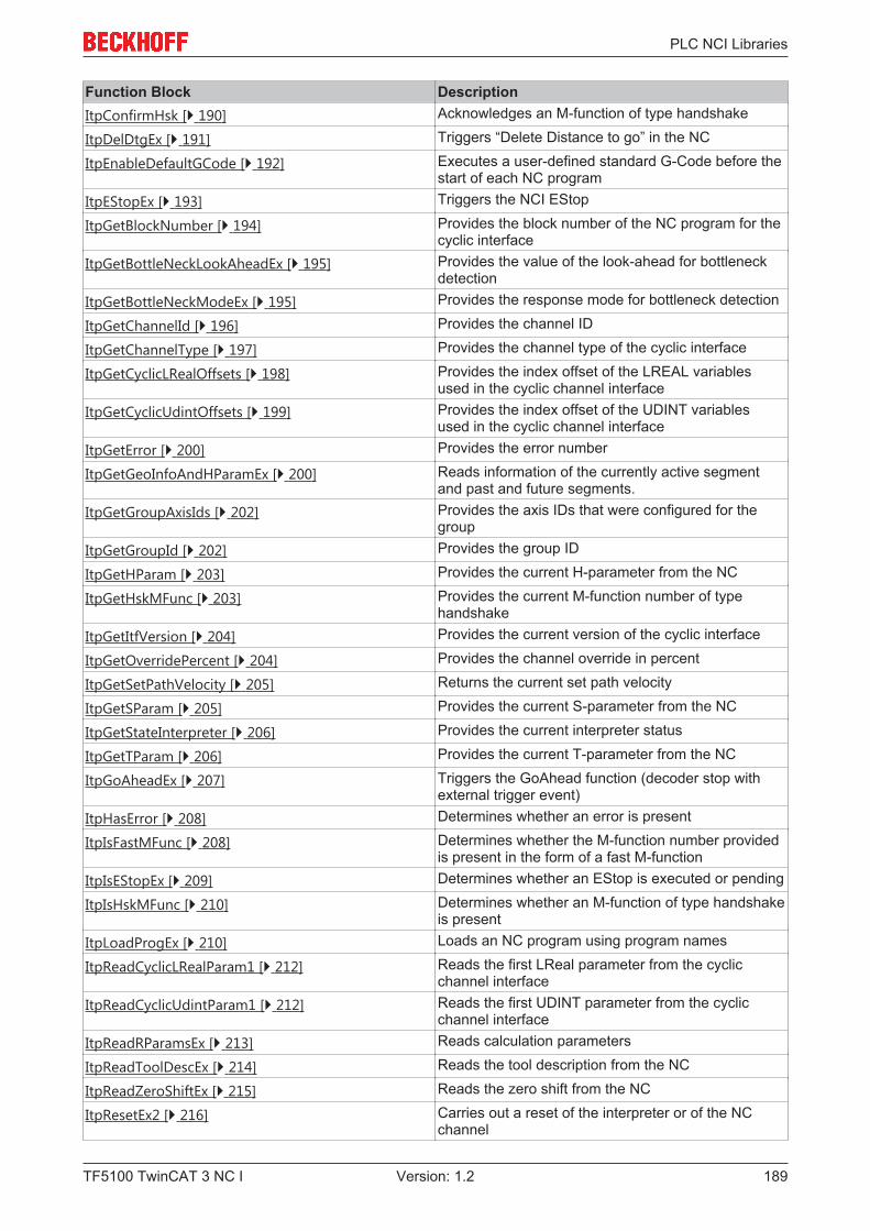
PLC NCI Libraries
TF5100 TwinCAT 3 NC I 189Version: 1.2
Function Block DescriptionItpConfirmHsk [} 190] Acknowledges an M-function of type handshake
ItpDelDtgEx [} 191] Triggers “Delete Distance to go” in the NC
ItpEnableDefaultGCode [} 192] Executes a user-defined standard G-Code before thestart of each NC program
ItpEStopEx [} 193] Triggers the NCI EStop
ItpGetBlockNumber [} 194] Provides the block number of the NC program for thecyclic interface
ItpGetBottleNeckLookAheadEx [} 195] Provides the value of the look-ahead for bottleneckdetection
ItpGetBottleNeckModeEx [} 195] Provides the response mode for bottleneck detection
ItpGetChannelId [} 196] Provides the channel ID
ItpGetChannelType [} 197] Provides the channel type of the cyclic interface
ItpGetCyclicLRealOffsets [} 198] Provides the index offset of the LREAL variablesused in the cyclic channel interface
ItpGetCyclicUdintOffsets [} 199] Provides the index offset of the UDINT variablesused in the cyclic channel interface
ItpGetError [} 200] Provides the error number
ItpGetGeoInfoAndHParamEx [} 200] Reads information of the currently active segmentand past and future segments.
ItpGetGroupAxisIds [} 202] Provides the axis IDs that were configured for thegroup
ItpGetGroupId [} 202] Provides the group ID
ItpGetHParam [} 203] Provides the current H-parameter from the NC
ItpGetHskMFunc [} 203] Provides the current M-function number of typehandshake
ItpGetItfVersion [} 204] Provides the current version of the cyclic interface
ItpGetOverridePercent [} 204] Provides the channel override in percent
ItpGetSetPathVelocity [} 205] Returns the current set path velocity
ItpGetSParam [} 205] Provides the current S-parameter from the NC
ItpGetStateInterpreter [} 206] Provides the current interpreter status
ItpGetTParam [} 206] Provides the current T-parameter from the NC
ItpGoAheadEx [} 207] Triggers the GoAhead function (decoder stop withexternal trigger event)
ItpHasError [} 208] Determines whether an error is present
ItpIsFastMFunc [} 208] Determines whether the M-function number providedis present in the form of a fast M-function
ItpIsEStopEx [} 209] Determines whether an EStop is executed or pending
ItpIsHskMFunc [} 210] Determines whether an M-function of type handshakeis present
ItpLoadProgEx [} 210] Loads an NC program using program names
ItpReadCyclicLRealParam1 [} 212] Reads the first LReal parameter from the cyclicchannel interface
ItpReadCyclicUdintParam1 [} 212] Reads the first UDINT parameter from the cyclicchannel interface
ItpReadRParamsEx [} 213] Reads calculation parameters
ItpReadToolDescEx [} 214] Reads the tool description from the NC
ItpReadZeroShiftEx [} 215] Reads the zero shift from the NC
ItpResetEx2 [} 216] Carries out a reset of the interpreter or of the NCchannel
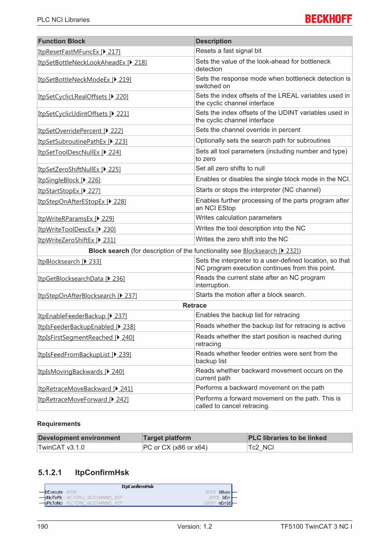
PLC NCI Libraries
TF5100 TwinCAT 3 NC I190 Version: 1.2
Function Block DescriptionItpResetFastMFuncEx [} 217] Resets a fast signal bit
ItpSetBottleNeckLookAheadEx [} 218] Sets the value of the look-ahead for bottleneckdetection
ItpSetBottleNeckModeEx [} 219] Sets the response mode when bottleneck detection isswitched on
ItpSetCyclicLRealOffsets [} 220] Sets the index offsets of the LREAL variables used inthe cyclic channel interface
ItpSetCyclicUdintOffsets [} 221] Sets the index offsets of the UDINT variables used inthe cyclic channel interface
ItpSetOverridePercent [} 222] Sets the channel override in percent
ItpSetSubroutinePathEx [} 223] Optionally sets the search path for subroutines
ItpSetToolDescNullEx [} 224] Sets all tool parameters (including number and type)to zero
ItpSetZeroShiftNullEx [} 225] Set all zero shifts to null
ItpSingleBlock [} 226] Enables or disables the single block mode in the NCI.
ItpStartStopEx [} 227] Starts or stops the interpreter (NC channel)
ItpStepOnAfterEStopEx [} 228] Enables further processing of the parts program afteran NCI EStop
ItpWriteRParamsEx [} 229] Writes calculation parameters
ItpWriteToolDescEx [} 230] Writes the tool description into the NC
ItpWriteZeroShiftEx [} 231] Writes the zero shift into the NC
Block search (for description of the functionality see Blocksearch [} 232])ItpBlocksearch [} 233] Sets the interpreter to a user-defined location, so that
NC program execution continues from this point.ItpGetBlocksearchData [} 236] Reads the current state after an NC program
interruption.ItpStepOnAfterBlocksearch [} 237] Starts the motion after a block search.
RetraceItpEnableFeederBackup [} 237] Enables the backup list for retracing
ItpIsFeederBackupEnabled [} 238] Reads whether the backup list for retracing is active
ItpIsFirstSegmentReached [} 240] Reads whether the start position is reached duringretracing
ItpIsFeedFromBackupList [} 239] Reads whether feeder entries were sent from thebackup list
ItpIsMovingBackwards [} 240] Reads whether backward movement occurs on thecurrent path
ItpRetraceMoveBackward [} 241] Performs a backward movement on the path
ItpRetraceMoveForward [} 242] Performs a forward movement on the path. This iscalled to cancel retracing.
Requirements
Development environment Target platform PLC libraries to be linkedTwinCAT v3.1.0 PC or CX (x86 or x64) Tc2_NCI
5.1.2.1 ItpConfirmHsk
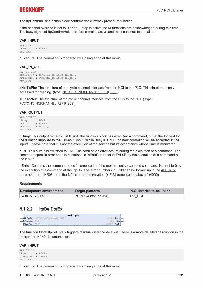
PLC NCI Libraries
TF5100 TwinCAT 3 NC I 191Version: 1.2
The ItpConfirmHsk function block confirms the currently present M-function.
If the channel override is set to 0 or an E-stop is active, no M-functions are acknowledged during this time.The busy signal of ItpConfirmHsk therefore remains active and must continue to be called.
VAR_INPUTVAR_INPUTbExecute : BOOL;END_VAR
bExecute: The command is triggered by a rising edge at this input.
VAR_IN_OUTVAR_IN_OUTsNciToPlc : NCTOPLC_NCICHANNEL_REF;sPlcToNci : PLCTONC_NCICHANNEL_REF;END_VAR
sNciToPlc: The structure of the cyclic channel interface from the NCI to the PLC. This structure is onlyaccessed for reading. (type: NCTOPLC_NCICHANNEL_REF [} 306])
sPlcToNci: The structure of the cyclic channel interface from the PLC to the NCI. (Type:PLCTONC_NCICHANNEL_REF [} 308])
VAR_OUTPUTVAR_OUTPUTbBusy : BOOL;bErr : BOOL;nErrId : UDINT;END_VAR
bBusy: This output remains TRUE until the function block has executed a command, but at the longest forthe duration supplied to the 'Timeout' input. While Busy = TRUE, no new command will be accepted at theinputs. Please note that it is not the execution of the service but its acceptance whose time is monitored.
bErr: This output is switched to TRUE as soon as an error occurs during the execution of a command. Thecommand-specific error code is contained in ‘nErrId’. Is reset to FALSE by the execution of a command atthe inputs.
nErrId: Contains the command-specific error code of the most recently executed command. Is reset to 0 bythe execution of a command at the inputs. The error numbers in ErrId can be looked up in the ADS errordocumentation [} 308] or in the NC error documentation [} 313] (error codes above 0x4000).
Requirements
Development environment Target platform PLC libraries to be linkedTwinCAT v3.1.0 PC or CX (x86 or x64) Tc2_NCI
5.1.2.2 ItpDelDtgEx
The function block ItpDelDtgEx triggers residual distance deletion. There is a more detailed description in theInterpreter [} 140]documentation.
VAR_INPUTVAR_INPUTbExecute : BOOL;tTimeOut : TIME;END_VAR
bExecute: The command is triggered by a rising edge at this input.
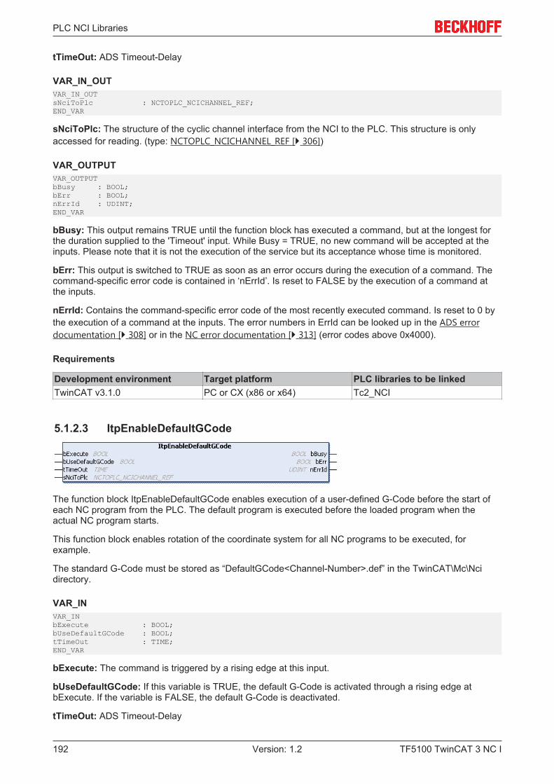
PLC NCI Libraries
TF5100 TwinCAT 3 NC I192 Version: 1.2
tTimeOut: ADS Timeout-Delay
VAR_IN_OUTVAR_IN_OUTsNciToPlc : NCTOPLC_NCICHANNEL_REF;END_VAR
sNciToPlc: The structure of the cyclic channel interface from the NCI to the PLC. This structure is onlyaccessed for reading. (type: NCTOPLC_NCICHANNEL_REF [} 306])
VAR_OUTPUTVAR_OUTPUTbBusy : BOOL;bErr : BOOL;nErrId : UDINT;END_VAR
bBusy: This output remains TRUE until the function block has executed a command, but at the longest forthe duration supplied to the 'Timeout' input. While Busy = TRUE, no new command will be accepted at theinputs. Please note that it is not the execution of the service but its acceptance whose time is monitored.
bErr: This output is switched to TRUE as soon as an error occurs during the execution of a command. Thecommand-specific error code is contained in ‘nErrId’. Is reset to FALSE by the execution of a command atthe inputs.
nErrId: Contains the command-specific error code of the most recently executed command. Is reset to 0 bythe execution of a command at the inputs. The error numbers in ErrId can be looked up in the ADS errordocumentation [} 308] or in the NC error documentation [} 313] (error codes above 0x4000).
Requirements
Development environment Target platform PLC libraries to be linkedTwinCAT v3.1.0 PC or CX (x86 or x64) Tc2_NCI
5.1.2.3 ItpEnableDefaultGCode
The function block ItpEnableDefaultGCode enables execution of a user-defined G-Code before the start ofeach NC program from the PLC. The default program is executed before the loaded program when theactual NC program starts.
This function block enables rotation of the coordinate system for all NC programs to be executed, forexample.
The standard G-Code must be stored as “DefaultGCode<Channel-Number>.def” in the TwinCAT\Mc\Ncidirectory.
VAR_INVAR_INbExecute : BOOL;bUseDefaultGCode : BOOL;tTimeOut : TIME;END_VAR
bExecute: The command is triggered by a rising edge at this input.
bUseDefaultGCode: If this variable is TRUE, the default G-Code is activated through a rising edge atbExecute. If the variable is FALSE, the default G-Code is deactivated.
tTimeOut: ADS Timeout-Delay
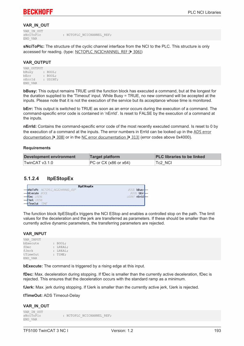
PLC NCI Libraries
TF5100 TwinCAT 3 NC I 193Version: 1.2
VAR_IN_OUTVAR_IN_OUTsNciToPlc : NCTOPLC_NCICHANNEL_REF;END_VAR
sNciToPlc: The structure of the cyclic channel interface from the NCI to the PLC. This structure is onlyaccessed for reading. (type: NCTOPLC_NCICHANNEL_REF [} 306])
VAR_OUTPUTVAR_OUTPUTbBusy : BOOL;bErr : BOOL;nErrId : UDINT;END_VAR
bBusy: This output remains TRUE until the function block has executed a command, but at the longest forthe duration supplied to the 'Timeout' input. While Busy = TRUE, no new command will be accepted at theinputs. Please note that it is not the execution of the service but its acceptance whose time is monitored.
bErr: This output is switched to TRUE as soon as an error occurs during the execution of a command. Thecommand-specific error code is contained in ‘nErrId’. Is reset to FALSE by the execution of a command atthe inputs.
nErrId: Contains the command-specific error code of the most recently executed command. Is reset to 0 bythe execution of a command at the inputs. The error numbers in ErrId can be looked up in the ADS errordocumentation [} 308] or in the NC error documentation [} 313] (error codes above 0x4000).
Requirements
Development environment Target platform PLC libraries to be linkedTwinCAT v3.1.0 PC or CX (x86 or x64) Tc2_NCI
5.1.2.4 ItpEStopEx
The function block ItpEStopEx triggers the NCI EStop and enables a controlled stop on the path. The limitvalues for the deceleration and the jerk are transferred as parameters. If these should be smaller than thecurrently active dynamic parameters, the transferring parameters are rejected.
VAR_INPUTVAR_INPUTbExecute : BOOL;fDec : LREAL;fJerk : LREAL;tTimeOut : TIME;END_VAR
bExecute: The command is triggered by a rising edge at this input.
fDec: Max. deceleration during stopping. If fDec is smaller than the currently active deceleration, fDec isrejected. This ensures that the deceleration occurs with the standard ramp as a minimum.
fJerk: Max. jerk during stopping. If fJerk is smaller than the currently active jerk, fJerk is rejected.
tTimeOut: ADS Timeout-Delay
VAR_IN_OUTVAR_IN_OUTsNciToPlc : NCTOPLC_NCICHANNEL_REF;END_VAR
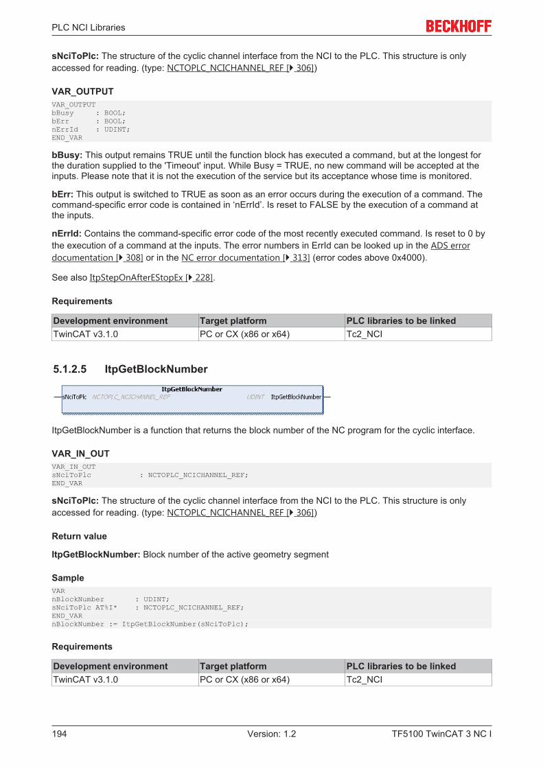
PLC NCI Libraries
TF5100 TwinCAT 3 NC I194 Version: 1.2
sNciToPlc: The structure of the cyclic channel interface from the NCI to the PLC. This structure is onlyaccessed for reading. (type: NCTOPLC_NCICHANNEL_REF [} 306])
VAR_OUTPUTVAR_OUTPUTbBusy : BOOL;bErr : BOOL;nErrId : UDINT;END_VAR
bBusy: This output remains TRUE until the function block has executed a command, but at the longest forthe duration supplied to the 'Timeout' input. While Busy = TRUE, no new command will be accepted at theinputs. Please note that it is not the execution of the service but its acceptance whose time is monitored.
bErr: This output is switched to TRUE as soon as an error occurs during the execution of a command. Thecommand-specific error code is contained in ‘nErrId’. Is reset to FALSE by the execution of a command atthe inputs.
nErrId: Contains the command-specific error code of the most recently executed command. Is reset to 0 bythe execution of a command at the inputs. The error numbers in ErrId can be looked up in the ADS errordocumentation [} 308] or in the NC error documentation [} 313] (error codes above 0x4000).
See also ItpStepOnAfterEStopEx [} 228].
Requirements
Development environment Target platform PLC libraries to be linkedTwinCAT v3.1.0 PC or CX (x86 or x64) Tc2_NCI
5.1.2.5 ItpGetBlockNumber
ItpGetBlockNumber is a function that returns the block number of the NC program for the cyclic interface.
VAR_IN_OUTVAR_IN_OUTsNciToPlc : NCTOPLC_NCICHANNEL_REF;END_VAR
sNciToPlc: The structure of the cyclic channel interface from the NCI to the PLC. This structure is onlyaccessed for reading. (type: NCTOPLC_NCICHANNEL_REF [} 306])
Return value
ItpGetBlockNumber: Block number of the active geometry segment
SampleVARnBlockNumber : UDINT;sNciToPlc AT%I* : NCTOPLC_NCICHANNEL_REF;END_VARnBlockNumber := ItpGetBlockNumber(sNciToPlc);
Requirements
Development environment Target platform PLC libraries to be linkedTwinCAT v3.1.0 PC or CX (x86 or x64) Tc2_NCI
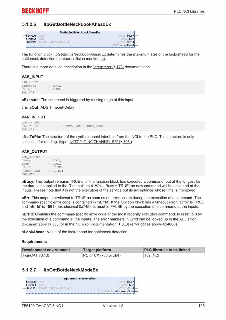
PLC NCI Libraries
TF5100 TwinCAT 3 NC I 195Version: 1.2
5.1.2.6 ItpGetBottleNeckLookAheadEx
The function block ItpGetBottleNeckLookAheadEx determines the maximum size of the look-ahead for thebottleneck detection (contour collision monitoring).
There is a more detailed description in the Interpreter [} 173] documentation.
VAR_INPUTVAR_INPUTbExecute : BOOL;tTimeOut : TIME;END_VAR
bExecute: The command is triggered by a rising edge at this input.
tTimeOut: ADS Timeout-Delay
VAR_IN_OUTVAR_IN_OUTsNciToPlc : NCTOPLC_NCICHANNEL_REF;END_VAR
sNciToPlc: The structure of the cyclic channel interface from the NCI to the PLC. This structure is onlyaccessed for reading. (type: NCTOPLC_NCICHANNEL_REF [} 306])
VAR_OUTPUTVAR_OUTPUTbBusy : BOOL;bErr : BOOL;nErrId : UDINT;nLookAhead : UDINT;END_VAR
bBusy: This output remains TRUE until the function block has executed a command, but at the longest forthe duration supplied to the 'Timeout' input. While Busy = TRUE, no new command will be accepted at theinputs. Please note that it is not the execution of the service but its acceptance whose time is monitored.
bErr: This output is switched to TRUE as soon as an error occurs during the execution of a command. Thecommand-specific error code is contained in ‘nErrId’. If the function block has a timeout error, ‘Error’ is TRUEand ‘nErrId’ is 1861 (hexadecimal 0x745). Is reset to FALSE by the execution of a command at the inputs.
nErrId: Contains the command-specific error code of the most recently executed command. Is reset to 0 bythe execution of a command at the inputs. The error numbers in ErrId can be looked up in the ADS errordocumentation [} 308] or in the NC error documentation [} 313] (error codes above 0x4000).
nLookAhead: Value of the look-ahead for bottleneck detection
Requirements
Development environment Target platform PLC libraries to be linkedTwinCAT v3.1.0 PC or CX (x86 or x64) Tc2_NCI
5.1.2.7 ItpGetBottleNeckModeEx
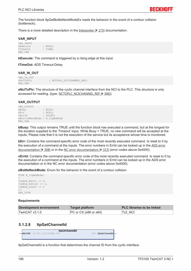
PLC NCI Libraries
TF5100 TwinCAT 3 NC I196 Version: 1.2
The function block ItpGetBottleNeckModeEx reads the behavior in the event of a contour collision(bottleneck).
There is a more detailed description in the Interpreter [} 173] documentation.
VAR_INPUTVAR_INPUTbExecute : BOOL;tTimeOut : TIME;END_VAR
bExecute: The command is triggered by a rising edge at this input.
tTimeOut: ADS Timeout-Delay
VAR_IN_OUTVAR_IN_OUTsNciToPlc : NCTOPLC_NCICHANNEL_REF;END_VAR
sNciToPlc: The structure of the cyclic channel interface from the NCI to the PLC. This structure is onlyaccessed for reading. (type: NCTOPLC_NCICHANNEL_REF [} 306])
VAR_OUTPUTVAR_OUTPUTbBusy : BOOL;bErr : BOOL;nErrId : UDINT;eBottleNeckMode : E_ItpBnModeEND_VAR
bBusy: This output remains TRUE until the function block has executed a command, but at the longest forthe duration supplied to the 'Timeout' input. While Busy = TRUE, no new command will be accepted at theinputs. Please note that it is not the execution of the service but its acceptance whose time is monitored.
bErr: Contains the command-specific error code of the most recently executed command. Is reset to 0 bythe execution of a command at the inputs. The error numbers in ErrId can be looked up in the ADS errordocumentation [} 308] or in the NC error documentation [} 313] (error codes above 0x4000).
nErrId: Contains the command-specific error code of the most recently executed command. Is reset to 0 bythe execution of a command at the inputs. The error numbers in ErrId can be looked up in the ADS errordocumentation or in the NC error documentation (error codes above 0x4000).
eBottleNeckMode: Enum for the behavior in the event of a contour collisionTYPE E_ItpBnMode:(ItpBnm_Abort := 0,ItpBnm_Adjust := 1,ItpBnm_Leave := 2);END_TYPE
Requirements
Development environment Target platform PLC libraries to be linkedTwinCAT v3.1.0 PC or CX (x86 or x64) Tc2_NCI
5.1.2.8 ItpGetChannelId
ItpGetChannelId is a function that determines the channel ID from the cyclic interface.
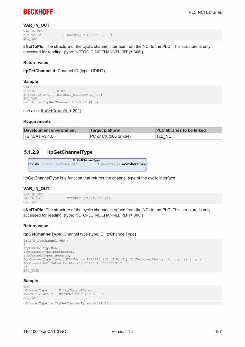
PLC NCI Libraries
TF5100 TwinCAT 3 NC I 197Version: 1.2
VAR_IN_OUTVAR_IN_OUTsNciToPlc : NCTOPLC_NCICHANNEL_REF;END_VAR
sNciToPlc: The structure of the cyclic channel interface from the NCI to the PLC. This structure is onlyaccessed for reading. (type: NCTOPLC_NCICHANNEL_REF [} 306])
Return value
ItpGetChannelId: Channel ID (type: UDINT)
SampleVARnChnId : UINT;sNciToPlc AT%I*: NCTOPLC_NCICHANNEL_REF;END_VARnChnId := ItpGetChannelId( sNciToPlc );
see also: ItpGetGroupId [} 202]
Requirements
Development environment Target platform PLC libraries to be linkedTwinCAT v3.1.0 PC or CX (x86 or x64) Tc2_NCI
5.1.2.9 ItpGetChannelType
ItpGetChannelType is a function that returns the channel type of the cyclic interface.
VAR_IN_OUTVAR_IN_OUTsNciToPlc : NCTOPLC_NCICHANNEL_REF;END_VAR
sNciToPlc: The structure of the cyclic channel interface from the NCI to the PLC. This structure is onlyaccessed for reading. (type: NCTOPLC_NCICHANNEL_REF [} 306])
Return value
ItpGetChannelType: Channel type (type: E_ItpChannelType)TYPE E_ItpChannelType :(ItpChannelTypeNone,ItpChannelTypeInterpreter,ItpChannelTypeKinematic,ItpChannelType_InvalidItfVer := 16#4B14 (*ErrTcNciItp_ItfVersion the cyclic channel inter-face does not match to the requested function/fb *));END_TYPE
SampleVARnChannelType : E_ItpChannelType;sNciToPlc AT%I* : NCTOPLC_NCICHANNEL_REF;END_VAR
nChannelType := ItpGetChannelType( sNciToPlc );
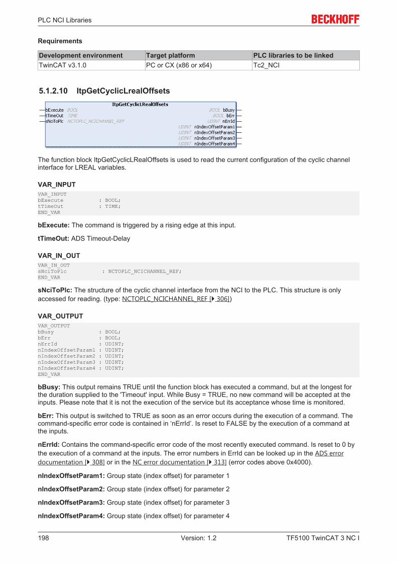
PLC NCI Libraries
TF5100 TwinCAT 3 NC I198 Version: 1.2
Requirements
Development environment Target platform PLC libraries to be linkedTwinCAT v3.1.0 PC or CX (x86 or x64) Tc2_NCI
5.1.2.10 ItpGetCyclicLrealOffsets
The function block ItpGetCyclicLRealOffsets is used to read the current configuration of the cyclic channelinterface for LREAL variables.
VAR_INPUTVAR_INPUTbExecute : BOOL;tTimeOut : TIME;END_VAR
bExecute: The command is triggered by a rising edge at this input.
tTimeOut: ADS Timeout-Delay
VAR_IN_OUTVAR_IN_OUTsNciToPlc : NCTOPLC_NCICHANNEL_REF;END_VAR
sNciToPlc: The structure of the cyclic channel interface from the NCI to the PLC. This structure is onlyaccessed for reading. (type: NCTOPLC_NCICHANNEL_REF [} 306])
VAR_OUTPUTVAR_OUTPUTbBusy : BOOL;bErr : BOOL;nErrId : UDINT;nIndexOffsetParam1 : UDINT;nIndexOffsetParam2 : UDINT;nIndexOffsetParam3 : UDINT;nIndexOffsetParam4 : UDINT;END_VAR
bBusy: This output remains TRUE until the function block has executed a command, but at the longest forthe duration supplied to the 'Timeout' input. While Busy = TRUE, no new command will be accepted at theinputs. Please note that it is not the execution of the service but its acceptance whose time is monitored.
bErr: This output is switched to TRUE as soon as an error occurs during the execution of a command. Thecommand-specific error code is contained in ‘nErrId’. Is reset to FALSE by the execution of a command atthe inputs.
nErrId: Contains the command-specific error code of the most recently executed command. Is reset to 0 bythe execution of a command at the inputs. The error numbers in ErrId can be looked up in the ADS errordocumentation [} 308] or in the NC error documentation [} 313] (error codes above 0x4000).
nIndexOffsetParam1: Group state (index offset) for parameter 1
nIndexOffsetParam2: Group state (index offset) for parameter 2
nIndexOffsetParam3: Group state (index offset) for parameter 3
nIndexOffsetParam4: Group state (index offset) for parameter 4
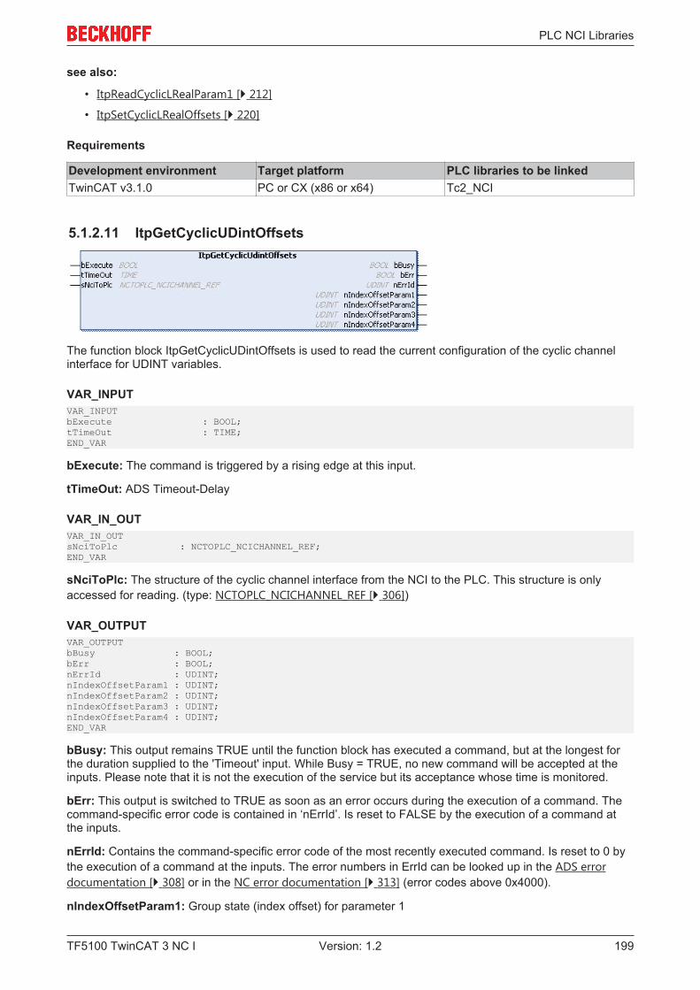
PLC NCI Libraries
TF5100 TwinCAT 3 NC I 199Version: 1.2
see also:
• ItpReadCyclicLRealParam1 [} 212]
• ItpSetCyclicLRealOffsets [} 220]
Requirements
Development environment Target platform PLC libraries to be linkedTwinCAT v3.1.0 PC or CX (x86 or x64) Tc2_NCI
5.1.2.11 ItpGetCyclicUDintOffsets
The function block ItpGetCyclicUDintOffsets is used to read the current configuration of the cyclic channelinterface for UDINT variables.
VAR_INPUTVAR_INPUTbExecute : BOOL;tTimeOut : TIME;END_VAR
bExecute: The command is triggered by a rising edge at this input.
tTimeOut: ADS Timeout-Delay
VAR_IN_OUTVAR_IN_OUTsNciToPlc : NCTOPLC_NCICHANNEL_REF;END_VAR
sNciToPlc: The structure of the cyclic channel interface from the NCI to the PLC. This structure is onlyaccessed for reading. (type: NCTOPLC_NCICHANNEL_REF [} 306])
VAR_OUTPUTVAR_OUTPUTbBusy : BOOL;bErr : BOOL;nErrId : UDINT;nIndexOffsetParam1 : UDINT;nIndexOffsetParam2 : UDINT;nIndexOffsetParam3 : UDINT;nIndexOffsetParam4 : UDINT;END_VAR
bBusy: This output remains TRUE until the function block has executed a command, but at the longest forthe duration supplied to the 'Timeout' input. While Busy = TRUE, no new command will be accepted at theinputs. Please note that it is not the execution of the service but its acceptance whose time is monitored.
bErr: This output is switched to TRUE as soon as an error occurs during the execution of a command. Thecommand-specific error code is contained in ‘nErrId’. Is reset to FALSE by the execution of a command atthe inputs.
nErrId: Contains the command-specific error code of the most recently executed command. Is reset to 0 bythe execution of a command at the inputs. The error numbers in ErrId can be looked up in the ADS errordocumentation [} 308] or in the NC error documentation [} 313] (error codes above 0x4000).
nIndexOffsetParam1: Group state (index offset) for parameter 1
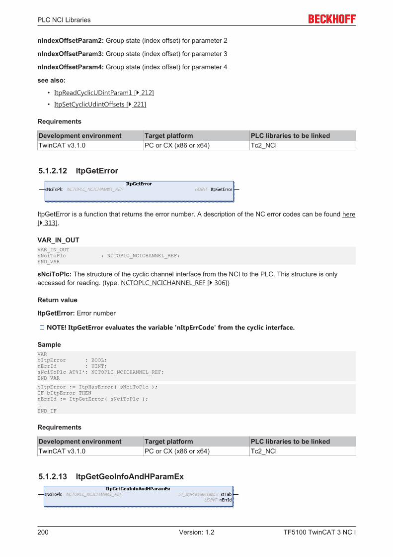
PLC NCI Libraries
TF5100 TwinCAT 3 NC I200 Version: 1.2
nIndexOffsetParam2: Group state (index offset) for parameter 2
nIndexOffsetParam3: Group state (index offset) for parameter 3
nIndexOffsetParam4: Group state (index offset) for parameter 4
see also:
• ItpReadCyclicUDintParam1 [} 212]
• ItpSetCyclicUdintOffsets [} 221]
Requirements
Development environment Target platform PLC libraries to be linkedTwinCAT v3.1.0 PC or CX (x86 or x64) Tc2_NCI
5.1.2.12 ItpGetError
ItpGetError is a function that returns the error number. A description of the NC error codes can be found here[} 313].
VAR_IN_OUTVAR_IN_OUTsNciToPlc : NCTOPLC_NCICHANNEL_REF;END_VAR
sNciToPlc: The structure of the cyclic channel interface from the NCI to the PLC. This structure is onlyaccessed for reading. (type: NCTOPLC_NCICHANNEL_REF [} 306])
Return value
ItpGetError: Error number
NOTE! ItpGetError evaluates the variable 'nItpErrCode' from the cyclic interface.
SampleVARbItpError : BOOL;nErrId : UINT;sNciToPlc AT%I*: NCTOPLC_NCICHANNEL_REF;END_VAR
bItpError := ItpHasError( sNciToPlc );IF bItpError THENnErrId := ItpGetError( sNciToPlc );…END_IF
Requirements
Development environment Target platform PLC libraries to be linkedTwinCAT v3.1.0 PC or CX (x86 or x64) Tc2_NCI
5.1.2.13 ItpGetGeoInfoAndHParamEx
PLC NCI Libraries
TF5100 TwinCAT 3 NC I 201Version: 1.2
The function block ItpGetGeoInfoAndHParamEx reads informations of the currently active segment andpast and future segments. These include block number, H-parameter and residual path length on thesegment.
VAR_IN_OUTVAR_IN_OUTsNciToPlc : NCTOPLC_NCICHANNEL_REF;END_VAR
sNciToPlc: The structure of the cyclic channel interface from the NCI to the PLC. This structure is onlyaccessed for reading. (type: NCTOPLC_NCICHANNEL_REF [} 306])
VAR_OUTPUTVAR_OUTPUTstTab : ST_ItpPreViewTabEx;nErrId : UDINT;END_VAR
stTab: Structure containing the segment data. See ST_ItpPreViewTabEx [} 201].
nErrId: Contains the command-specific error code of the most recently executed command. Is reset to 0 bythe execution of a command at the inputs. The error numbers in nErrId can be looked up in the ADS errordocumentation [} 308] or in the NC error documentation [} 313] (error codes above 0x4000).TYPE ST_ItpPreViewTabEx :STRUCTnDcTime : UDINT := 0nReserved : UDINT := 0;arrLines : ARRAY[1..NCI_MAX_PREVIEWTABLINES] OF ST_ItpPreViewTabLine;END_STRUCTEND_TYPE
nDcTime: Current time stamp in ns. This time stamp can be used e.g. in interplay with the Tc2_NciXFClibrary.
arrLines: Array of segment-related information (size 20). The entry at position 11 of the array corresponds tothe currently active segment. Segments that have already been processed are displayed at positions 1-10 ofthe array, future segments at positions 12-20. See ST_ItpPreViewTabLine [} 201].TYPE ST_ItpPreViewTabLine :STRUCTfLength : LREAL := 0.0;nBlockNo : UDINT := 0;nHParam : UDINT := 0;nEntryID : UDINT := 0;nReserved : UDINT := 0;END_STRUCTEND_TYPE
fLength: Remaining segment length. For segments that are not yet active this corresponds to the totalsegment length. For past segments the distance moved since the end of the segment is specified.
nBlockNo: Block number programmed by the user
nHParam: Value of the H-parameter [} 149] that is active from the start of the next segment
nEntryID: Command ID generated by the system
Requirements
Development environment Target platform PLC libraries to be linkedTwinCAT v3.1.0 PC or CX (x86 or x64) Tc2_NCI
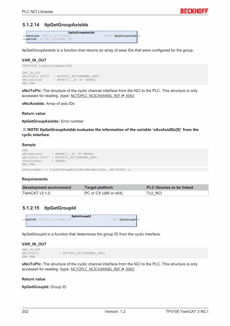
PLC NCI Libraries
TF5100 TwinCAT 3 NC I202 Version: 1.2
5.1.2.14 ItpGetGroupAxisIds
ItpGetGroupAxisIds is a function that returns an array of axes IDs that were configured for the group.
VAR_IN_OUTFUNCTION ItpGetGroupAxisIds
VAR_IN_OUTsNciToPlc AT%I* : NCTOPLC_NCICHANNEL_REF;nNciAxisIds : ARRAY[1..8] OF DWORD;END_VAR
sNciToPlc: The structure of the cyclic channel interface from the NCI to the PLC. This structure is onlyaccessed for reading. (type: NCTOPLC_NCICHANNEL_REF [} 306])
sNciAxisIds: Array of axis IDs
Return value
ItpGetGroupAxisIds: Error number
NOTE! ItpGetGroupAxisIds evaluates the information of the variable 'nAcsAxisIDs[8]' from thecyclic interface.
SampleVARnNciAxisIds : ARRAY[1..8] OF DWORD;sNciToPlc AT%I* : NCTOPLC_NCICHANNEL_REF;nVersionErr : DWORD;END_VAR
nVersionErr := ItpGetGroupAxisIds(nNciAxisIds, sNciToPlc );
Requirements
Development environment Target platform PLC libraries to be linkedTwinCAT v3.1.0 PC or CX (x86 or x64) Tc2_NCI
5.1.2.15 ItpGetGroupId
ItpGetGroupId is a function that determines the group ID from the cyclic interface.
VAR_IN_OUTVAR_IN_OUTsNciToPlc : NCTOPLC_NCICHANNEL_REF;END_VAR
sNciToPlc: The structure of the cyclic channel interface from the NCI to the PLC. This structure is onlyaccessed for reading. (type: NCTOPLC_NCICHANNEL_REF [} 306])
Return value
ItpGetGroupId: Group ID
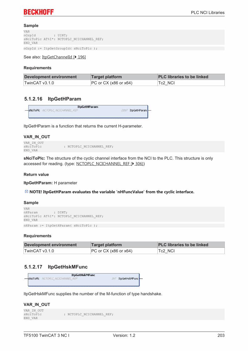
PLC NCI Libraries
TF5100 TwinCAT 3 NC I 203Version: 1.2
SampleVARnGrpId : UINT;sNciToPlc AT%I*: NCTOPLC_NCICHANNEL_REF;END_VAR
nGrpId := ItpGetGroupId( sNciToPlc );
See also: ItpGetChannelId [} 196]
Requirements
Development environment Target platform PLC libraries to be linkedTwinCAT v3.1.0 PC or CX (x86 or x64) Tc2_NCI
5.1.2.16 ItpGetHParam
ItpGetHParam is a function that returns the current H-parameter.
VAR_IN_OUTVAR_IN_OUTsNciToPlc : NCTOPLC_NCICHANNEL_REF;END_VAR
sNciToPlc: The structure of the cyclic channel interface from the NCI to the PLC. This structure is onlyaccessed for reading. (type: NCTOPLC_NCICHANNEL_REF [} 306])
Return value
ItpGetHParam: H parameter
NOTE! ItpGetHParam evaluates the variable 'nHFuncValue' from the cyclic interface.
SampleVARnHParam : DINT;sNciToPlc AT%I*: NCTOPLC_NCICHANNEL_REF;END_VAR
nHParam := ItpGetHParam( sNciToPlc );
Requirements
Development environment Target platform PLC libraries to be linkedTwinCAT v3.1.0 PC or CX (x86 or x64) Tc2_NCI
5.1.2.17 ItpGetHskMFunc
ItpGetHskMFunc supplies the number of the M-function of type handshake.
VAR_IN_OUTVAR_IN_OUTsNciToPlc : NCTOPLC_NCICHANNEL_REF;END_VAR
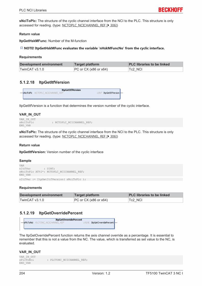
PLC NCI Libraries
TF5100 TwinCAT 3 NC I204 Version: 1.2
sNciToPlc: The structure of the cyclic channel interface from the NCI to the PLC. This structure is onlyaccessed for reading. (type: NCTOPLC_NCICHANNEL_REF [} 306])
Return value
ItpGetHskMFunc: Number of the M-function
NOTE! ItpGetHskMFunc evaluates the variable 'nHskMFuncNo' from the cyclic interface.
Requirements
Development environment Target platform PLC libraries to be linkedTwinCAT v3.1.0 PC or CX (x86 or x64) Tc2_NCI
5.1.2.18 ItpGetItfVersion
ItpGetItfVersion is a function that determines the version number of the cyclic interface.
VAR_IN_OUTVAR_IN_OUTsNciToPlc : NCTOPLC_NCICHANNEL_REF;END_VAR
sNciToPlc: The structure of the cyclic channel interface from the NCI to the PLC. This structure is onlyaccessed for reading. (type: NCTOPLC_NCICHANNEL_REF [} 306])
Return value
ItpGetItfVersion: Version number of the cyclic interface
SampleVARnItfVer : UINT;sNciToPlc AT%I*: NCTOPLC_NCICHANNEL_REF;END_VAR
nItfVer := ItpGetItfVersion( sNciToPlc );
Requirements
Development environment Target platform PLC libraries to be linkedTwinCAT v3.1.0 PC or CX (x86 or x64) Tc2_NCI
5.1.2.19 ItpGetOverridePercent
The ItpGetOverridePercent function returns the axis channel override as a percentage. It is essential toremember that this is not a value from the NC. The value, which is transferred as set value to the NC, isevaluated.
VAR_IN_OUTVAR_IN_OUTsPlcToNci : PLCTONC_NCICHANNEL_REF;END_VAR
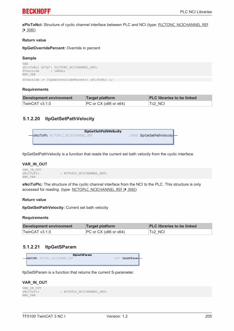
PLC NCI Libraries
TF5100 TwinCAT 3 NC I 205Version: 1.2
sPlcToNci: Structure of cyclic channel interface between PLC and NCI (type: PLCTONC_NCICHANNEL_REF[} 308])
Return value
ItpGetOverridePercent: Override in percent
SampleVARsPlcToNci AT%Q*: PLCTONC_NCICHANNEL_REF;fOverride : LREAL;END_VAR
fOverride := ItpGetOverridePercent( sPlcToNci );
Requirements
Development environment Target platform PLC libraries to be linkedTwinCAT v3.1.0 PC or CX (x86 or x64) Tc2_NCI
5.1.2.20 ItpGetSetPathVelocity
ItpGetSetPathVelocity is a function that reads the current set bath velocity from the cyclic interface.
VAR_IN_OUTVAR_IN_OUTsNciToPlc : NCTOPLC_NCICHANNEL_REF;END_VAR
sNciToPlc: The structure of the cyclic channel interface from the NCI to the PLC. This structure is onlyaccessed for reading. (type: NCTOPLC_NCICHANNEL_REF [} 306])
Return value
ItpGetSetPathVelocity: Current set bath velocity
Requirements
Development environment Target platform PLC libraries to be linkedTwinCAT v3.1.0 PC or CX (x86 or x64) Tc2_NCI
5.1.2.21 ItpGetSParam
ItpGetSParam is a function that returns the current S-parameter.
VAR_IN_OUTVAR_IN_OUTsNciToPlc : NCTOPLC_NCICHANNEL_REF;END_VAR
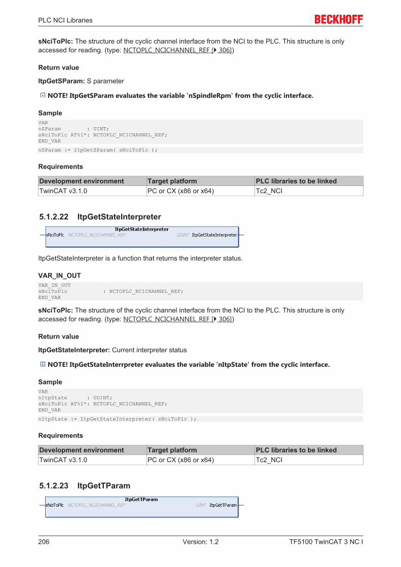
PLC NCI Libraries
TF5100 TwinCAT 3 NC I206 Version: 1.2
sNciToPlc: The structure of the cyclic channel interface from the NCI to the PLC. This structure is onlyaccessed for reading. (type: NCTOPLC_NCICHANNEL_REF [} 306])
Return value
ItpGetSParam: S parameter
NOTE! ItpGetSParam evaluates the variable 'nSpindleRpm' from the cyclic interface.
SampleVARnSParam : UINT;sNciToPlc AT%I*: NCTOPLC_NCICHANNEL_REF;END_VAR
nSParam := ItpGetSParam( sNciToPlc );
Requirements
Development environment Target platform PLC libraries to be linkedTwinCAT v3.1.0 PC or CX (x86 or x64) Tc2_NCI
5.1.2.22 ItpGetStateInterpreter
ItpGetStateInterpreter is a function that returns the interpreter status.
VAR_IN_OUTVAR_IN_OUTsNciToPlc : NCTOPLC_NCICHANNEL_REF;END_VAR
sNciToPlc: The structure of the cyclic channel interface from the NCI to the PLC. This structure is onlyaccessed for reading. (type: NCTOPLC_NCICHANNEL_REF [} 306])
Return value
ItpGetStateInterpreter: Current interpreter status
NOTE! ItpGetStateInterrpreter evaluates the variable 'nItpState' from the cyclic interface.
SampleVARnItpState : UDINT;sNciToPlc AT%I*: NCTOPLC_NCICHANNEL_REF;END_VAR
nItpState := ItpGetStateInterpreter( sNciToPlc );
Requirements
Development environment Target platform PLC libraries to be linkedTwinCAT v3.1.0 PC or CX (x86 or x64) Tc2_NCI
5.1.2.23 ItpGetTParam
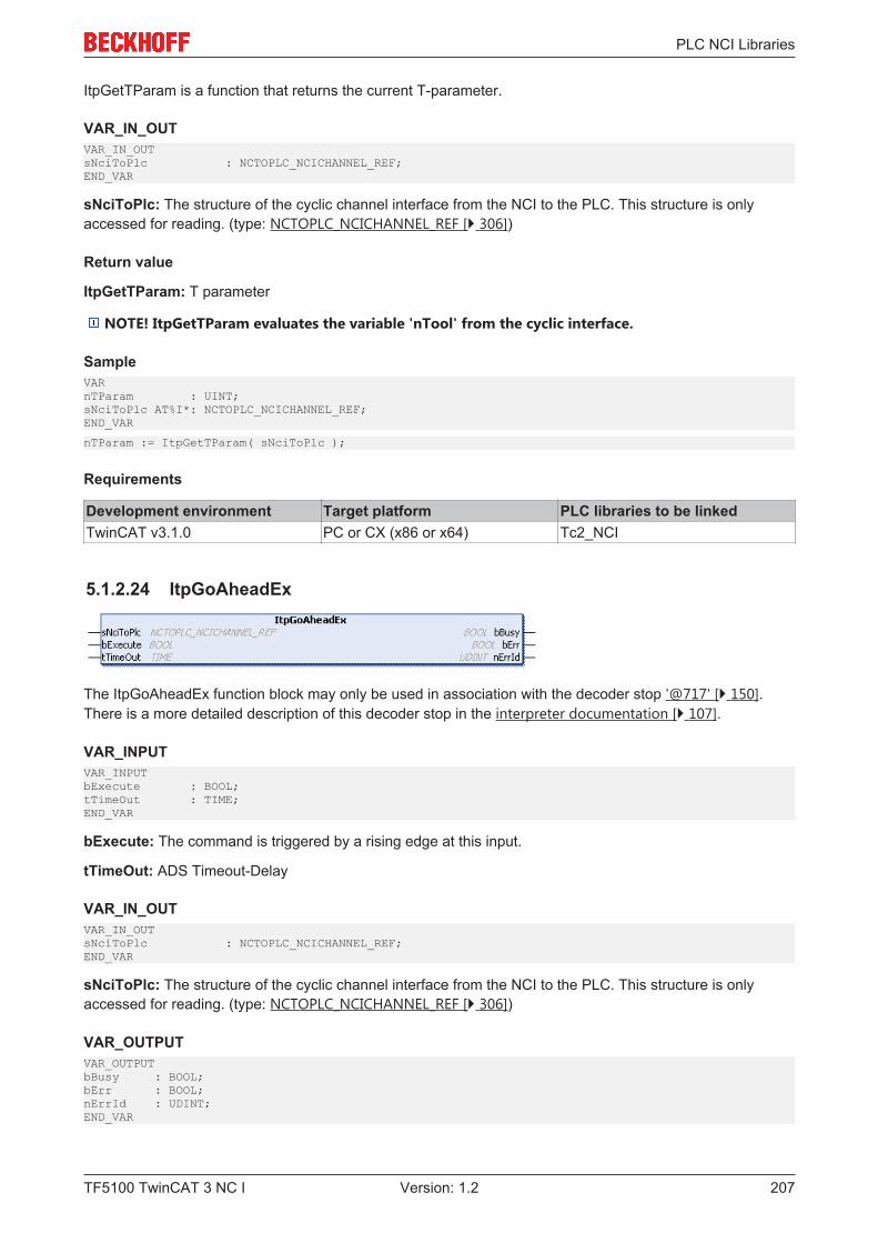
PLC NCI Libraries
TF5100 TwinCAT 3 NC I 207Version: 1.2
ItpGetTParam is a function that returns the current T-parameter.
VAR_IN_OUTVAR_IN_OUTsNciToPlc : NCTOPLC_NCICHANNEL_REF;END_VAR
sNciToPlc: The structure of the cyclic channel interface from the NCI to the PLC. This structure is onlyaccessed for reading. (type: NCTOPLC_NCICHANNEL_REF [} 306])
Return value
ItpGetTParam: T parameter
NOTE! ItpGetTParam evaluates the variable 'nTool' from the cyclic interface.
SampleVARnTParam : UINT;sNciToPlc AT%I*: NCTOPLC_NCICHANNEL_REF;END_VAR
nTParam := ItpGetTParam( sNciToPlc );
Requirements
Development environment Target platform PLC libraries to be linkedTwinCAT v3.1.0 PC or CX (x86 or x64) Tc2_NCI
5.1.2.24 ItpGoAheadEx
The ItpGoAheadEx function block may only be used in association with the decoder stop '@717' [} 150].There is a more detailed description of this decoder stop in the interpreter documentation [} 107].
VAR_INPUTVAR_INPUTbExecute : BOOL;tTimeOut : TIME;END_VAR
bExecute: The command is triggered by a rising edge at this input.
tTimeOut: ADS Timeout-Delay
VAR_IN_OUTVAR_IN_OUTsNciToPlc : NCTOPLC_NCICHANNEL_REF;END_VAR
sNciToPlc: The structure of the cyclic channel interface from the NCI to the PLC. This structure is onlyaccessed for reading. (type: NCTOPLC_NCICHANNEL_REF [} 306])
VAR_OUTPUTVAR_OUTPUTbBusy : BOOL;bErr : BOOL;nErrId : UDINT;END_VAR
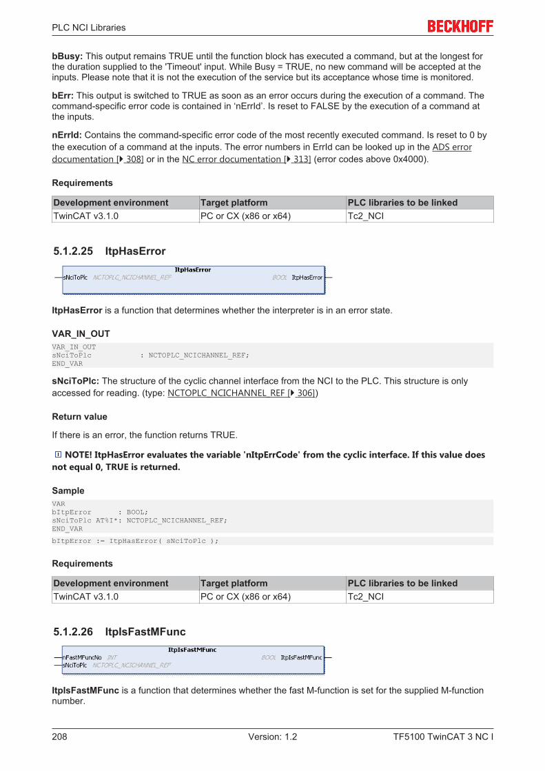
PLC NCI Libraries
TF5100 TwinCAT 3 NC I208 Version: 1.2
bBusy: This output remains TRUE until the function block has executed a command, but at the longest forthe duration supplied to the 'Timeout' input. While Busy = TRUE, no new command will be accepted at theinputs. Please note that it is not the execution of the service but its acceptance whose time is monitored.
bErr: This output is switched to TRUE as soon as an error occurs during the execution of a command. Thecommand-specific error code is contained in ‘nErrId’. Is reset to FALSE by the execution of a command atthe inputs.
nErrId: Contains the command-specific error code of the most recently executed command. Is reset to 0 bythe execution of a command at the inputs. The error numbers in ErrId can be looked up in the ADS errordocumentation [} 308] or in the NC error documentation [} 313] (error codes above 0x4000).
Requirements
Development environment Target platform PLC libraries to be linkedTwinCAT v3.1.0 PC or CX (x86 or x64) Tc2_NCI
5.1.2.25 ItpHasError
ItpHasError is a function that determines whether the interpreter is in an error state.
VAR_IN_OUTVAR_IN_OUTsNciToPlc : NCTOPLC_NCICHANNEL_REF;END_VAR
sNciToPlc: The structure of the cyclic channel interface from the NCI to the PLC. This structure is onlyaccessed for reading. (type: NCTOPLC_NCICHANNEL_REF [} 306])
Return value
If there is an error, the function returns TRUE.
NOTE! ItpHasError evaluates the variable 'nItpErrCode' from the cyclic interface. If this value doesnot equal 0, TRUE is returned.
SampleVARbItpError : BOOL;sNciToPlc AT%I*: NCTOPLC_NCICHANNEL_REF;END_VAR
bItpError := ItpHasError( sNciToPlc );
Requirements
Development environment Target platform PLC libraries to be linkedTwinCAT v3.1.0 PC or CX (x86 or x64) Tc2_NCI
5.1.2.26 ItpIsFastMFunc
ItpIsFastMFunc is a function that determines whether the fast M-function is set for the supplied M-functionnumber.
PLC NCI Libraries
TF5100 TwinCAT 3 NC I 209Version: 1.2
VAR_INFUNCTION ItpIsFastMFunc
VAR_INnFastMFuncNo : INT;END_VAR
nFastMFuncNo: Number of the M-function that is to be checked.
VAR_IN_OUTVAR_IN_OUTsNciToPlc : NCTOPLC_NCICHANNEL_REF;END_VAR
sNciToPlc: The structure of the cyclic channel interface from the NCI to the PLC. This structure is onlyaccessed for reading. (type: NCTOPLC_NCICHANNEL_REF [} 306])
Return value
The function returns TRUE if the fast bit of the M-function is set.
NOTE! ItpIsFastMFunc evaluates the variable 'nFastMFuncMask' from the cyclic interface.
Sample(*this enum is defined by the user *)
TYPE FastMFuncs: (M10_CoolingFluidOn := 10, (*fast M-Funktion M10*)M11_CoolingFluidOff := 11,M12_FanOn := 12,M13_FanOff := 13);END_TYPE
VARsNciToPlc AT%I*: NCTOPLC_NCICHANNEL_REFenFastMFuncs : FastMFuncs;bTurnFanOn : BOOL;END_VAR
bTurnFanOn := ItpIsFastMFunc( M12_FanOn,sNciToPlc );
Requirements
Development environment Target platform PLC libraries to be linkedTwinCAT v3.1.0 PC or CX (x86 or x64) Tc2_NCI
5.1.2.27 ItpIsEStopEx
The function ItpIsEStopEx indicates whether an EStop command was triggered.
VAR_IN_OUTVAR_IN_OUTsNciToPlc : NCTOPLC_NCICHANNEL_REF;END_VAR
sNciToPlc: The structure of the cyclic channel interface from the NCI to the PLC. This structure is onlyaccessed for reading. (type: NCTOPLC_NCICHANNEL_REF [} 306])

PLC NCI Libraries
TF5100 TwinCAT 3 NC I210 Version: 1.2
Return value
If the return value is TRUE, the function was preceded by an EStop (e.g. ItpEStopEx). The flag does notprovide information as to whether the axes have already stopped or are still on the braking ramp.
After execution of ItpStepOnAfterEStopEx, ItpIsEStopEx returns FALSE again.
NOTE! ItpIsEStopEx evaluates the cyclic interface.
see also:
ItpEStopEx [} 193]
ItpStepOnAfterEStopEx [} 228]
Requirements
Development environment Target platform PLC libraries to be linkedTwinCAT v3.1.0 PC or CX (x86 or x64) Tc2_NCI
5.1.2.28 ItpIsHskMFunc
ItpIsHskMFunc determines whether an M-function of type handshake is present.
VAR_IN_OUTVAR_IN_OUTsNciToPlc : NCTOPLC_NCICHANNEL_REF;END_VAR
sNciToPlc: The structure of the cyclic channel interface from the NCI to the PLC. This structure is onlyaccessed for reading. (type: NCTOPLC_NCICHANNEL_REF [} 306])
Return value
The function returns TRUE if an M-function of type handshake is present.
NOTE! ItpIsHskFunc evaluates the variable 'nHskMFuncReq' from the cyclic interface.
SampleVARbMFuncRequest : BOOL;sNciToPlc AT%I* : NCTOPLC_NCICHANNEL_REF; END_VAR
bMFuncRequest := ItpIsHskMFunc( sNciToPlc );
Requirements
Development environment Target platform PLC libraries to be linkedTwinCAT v3.1.0 PC or CX (x86 or x64) Tc2_NCI
5.1.2.29 ItpLoadProgEx
PLC NCI Libraries
TF5100 TwinCAT 3 NC I 211Version: 1.2
VAR_INPUTVAR_INPUTbExecute : BOOL;sPrg : STRING(255);nLength : UDINT;tTimeOut : TIME;END_VAR
bExecute: The function block reads the NC program when a rising edge is encountered
sPrg: Name of the NC program that is loaded
nLength: String length of the program name
tTimeOut: ADS Timeout-Delay
The NC program is looked up in directory "TwinCAT\Mc\Nci", if no further information is available. It ishowever also possible to give an absolute path.
VAR_IN_OUTVAR_IN_OUTsNciToPlc : NCTOPLC_NCICHANNEL_REF;END_VAR
sNciToPlc: The structure of the cyclic channel interface from the NCI to the PLC. This structure is onlyaccessed for reading. (type: NCTOPLC_NCICHANNEL_REF [} 306])
VAR_OUTPUTVAR_OUTPUTbBusy : BOOL;bErr : BOOL;nErrId : UDINT;END_VAR
bBusy: This output remains TRUE until the function block has executed a command, but at the longest forthe duration supplied to the 'Timeout' input. While Busy = TRUE, no new command will be accepted at theinputs. Please note that it is not the execution of the service but its acceptance whose time is monitored.
bErr: This output is switched to TRUE as soon as an error occurs during the execution of a command. Thecommand-specific error code is contained in ‘nErrId’. Is reset to FALSE by the execution of a command atthe inputs.
nErrId: Contains the command-specific error code of the most recently executed command. Is reset to 0 bythe execution of a command at the inputs. The error numbers in ErrId can be looked up in the ADS errordocumentation [} 308] or in the NC error documentation [} 313] (error codes above 0x4000).
SampleVARin_stItpToPlc AT %I* : NCTOPLC_NCICHANNEL_REF;fbLoadProg : ItpLoadProgEx;sProgramPath : STRING (255):= 'TestIt.nc';END_VAR
fbLoadProg(bExecute := TRUE,sPrg := sProgramPath,nLength := LEN(sProgramPath),tTimeOut := t#200ms,sNciToPlc := in_stItpToPlc );
Requirements
Development environment Target platform PLC libraries to be linkedTwinCAT v3.1.0 PC or CX (x86 or x64) Tc2_NCI
PLC NCI Libraries
TF5100 TwinCAT 3 NC I212 Version: 1.2
5.1.2.30 ItpReadCyclicLRealParam1
This function reads the first LREAL parameter from the cyclic channel interface. This parameter is configuredpreviously with ItpSetCyclicLRealOffsets [} 220].
Parameter 2 to 4 are read via the same mechanism (e.g. ItpReadCyclicLRealParam2).
VAR_IN_OUTVAR_IN_OUTsNciToPlc : NCTOPLC_NCICHANNEL_REF;END_VAR
sNciToPlc: The structure of the cyclic channel interface from the NCI to the PLC. This structure is onlyaccessed for reading. (type: NCTOPLC_NCICHANNEL_REF [} 306])
Return value
Parameter 1 of type LREAL.
See also:
• ItpReadCyclicUdintParam1 [} 212]
• ItpSetCyclicLRealOffsets [} 220]
• ItpGetCyclicLRealOffsets [} 198]
Requirements
Development environment Target platform PLC libraries to be linkedTwinCAT v3.1.0 PC or CX (x86 or x64) Tc2_NCI
5.1.2.31 ItpReadCyclicUdintParam1
This function reads the first UDINT parameter from the cyclic channel interface. This parameter is configuredpreviously with ItpSetCyclicUdintOffsets [} 221].
Parameter 2 to 4 are read via the same mechanism (e.g. ItpReadCyclicUdintParam2).
VAR_IN_OUTVAR_IN_OUTsNciToPlc : NCTOPLC_NCICHANNEL_REF;END_VAR
sNciToPlc: The structure of the cyclic channel interface from the NCI to the PLC. This structure is onlyaccessed for reading. (type: NCTOPLC_NCICHANNEL_REF [} 306])
Return value
Parameter 1 of type UDINT.
See also:
• ItpReadCyclicLRealParam1 [} 212]
• ItpSetCyclicUdintOffsets [} 221]
PLC NCI Libraries
TF5100 TwinCAT 3 NC I 213Version: 1.2
• ItpGetCyclicUdintOffsets [} 199]
Requirements
Development environment Target platform PLC libraries to be linkedTwinCAT v3.1.0 PC or CX (x86 or x64) Tc2_NCI
5.1.2.32 ItpReadRParamsEx
The ItpReadRParamsEx function block reads the NC’s calculation parameters, also known as R-parameters.A more detailed description of the calculation parameters can be found here [} 115]. A total of 1000 R-parameters are available, of which the first 900 (0..899) are local, so that they are only visible in the currentNC channel. The other 100 (900..999) R-parameters are global, and are thus visible from anywhere in theNC.
VAR_INPUTVAR_INPUTbExecute : BOOL;pAddr : PVOID;nIndex : DINT;nCount : DINT;tTimeOut : TIME;END_VAR
bExecute: A rising edge starts the read operation.
pAddr: Address of the target variables of the data to be read. Data are written directly from the specifiedaddress, i.e. nIndex is not to be interpreted as offset from pAddr. The data are usually stored in an array oftype LREAL, which has to be defined by the user.
nIndex: Describes the index of the R-parameter to be read from an NC perspective.
nCount: Number of R-parameters to be read
tTimeOut: ADS Timeout-Delay
VAR_IN_OUTVAR_IN_OUTsNciToPlc : NCTOPLC_NCICHANNEL_REF;END_VAR
sNciToPlc: The structure of the cyclic channel interface from the NCI to the PLC. This structure is onlyaccessed for reading. (type: NCTOPLC_NCICHANNEL_REF [} 306])
VAR_OUTPUTVAR_OUTPUTbBusy : BOOL;bErr : BOOL;nErrId : UDINT;END_VAR
bBusy: This output remains TRUE until the function block has executed a command, but at the longest forthe duration supplied to the 'Timeout' input. While Busy = TRUE, no new command will be accepted at theinputs. Please note that it is not the execution of the service but its acceptance whose time is monitored.
bErr: This output is switched to TRUE as soon as an error occurs during the execution of a command. Thecommand-specific error code is contained in ‘nErrId’. Is reset to FALSE by the execution of a command atthe inputs.
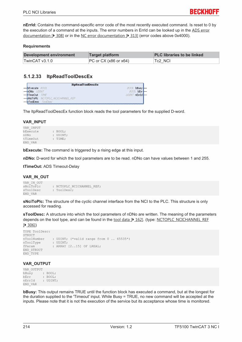
PLC NCI Libraries
TF5100 TwinCAT 3 NC I214 Version: 1.2
nErrId: Contains the command-specific error code of the most recently executed command. Is reset to 0 bythe execution of a command at the inputs. The error numbers in ErrId can be looked up in the ADS errordocumentation [} 308] or in the NC error documentation [} 313] (error codes above 0x4000).
Requirements
Development environment Target platform PLC libraries to be linkedTwinCAT v3.1.0 PC or CX (x86 or x64) Tc2_NCI
5.1.2.33 ItpReadToolDescEx
The ItpReadToolDescEx function block reads the tool parameters for the supplied D-word.
VAR_INPUTVAR_INPUTbExecute : BOOL;nDNo : UDINT;tTimeOut : TIME;END_VAR
bExecute: The command is triggered by a rising edge at this input.
nDNo: D-word for which the tool parameters are to be read. nDNo can have values between 1 and 255.
tTimeOut: ADS Timeout-Delay
VAR_IN_OUTVAR_IN_OUTsNciToPlc : NCTOPLC_NCICHANNEL_REF;sToolDesc : ToolDesc;END_VAR
sNciToPlc: The structure of the cyclic channel interface from the NCI to the PLC. This structure is onlyaccessed for reading.
sToolDesc: A structure into which the tool parameters of nDNo are written. The meaning of the parametersdepends on the tool type, and can be found in the tool data [} 162]. (type: NCTOPLC_NCICHANNEL_REF[} 306])TYPE ToolDesc:STRUCTnToolNumber : UDINT; (*valid range from 0 .. 65535*)nToolType : UDINT;fParam : ARRAY [2..15] OF LREAL;END_STRUCTEND_TYPE
VAR_OUTPUTVAR_OUTPUTbBusy : BOOL;bErr : BOOL;nErrId : UDINT;END_VAR
bBusy: This output remains TRUE until the function block has executed a command, but at the longest forthe duration supplied to the 'Timeout' input. While Busy = TRUE, no new command will be accepted at theinputs. Please note that it is not the execution of the service but its acceptance whose time is monitored.

PLC NCI Libraries
TF5100 TwinCAT 3 NC I 215Version: 1.2
bErr: This output is switched to TRUE as soon as an error occurs during the execution of a command. Thecommand-specific error code is contained in ‘nErrId’. Is reset to FALSE by the execution of a command atthe inputs.
nErrId: Contains the command-specific error code of the most recently executed command. Is reset to 0 bythe execution of a command at the inputs. The error numbers in ErrId can be looked up in the ADS errordocumentation [} 308] or in the NC error documentation [} 313] (error codes above 0x4000).
See also:
ItpWriteToolDescEx [} 230]
ItpSetToolDescNullEx [} 224]
Requirements
Development environment Target platform PLC libraries to be linkedTwinCAT v3.1.0 PC or CX (x86 or x64) Tc2_NCI
5.1.2.34 ItpReadZeroShiftEx
The ItpReadZeroShiftEx function block reads the zero shift components X, Y and Z for the given zero shift.
VAR_INPUTVAR_INPUTbExecute : BOOL;nZsNo : UDINT;tTimeOut : TIME;END_VAR
bExecute: The command is triggered by a rising edge at this input.
nZsNo: Number of the zero shift. G54 to G59 are zero shifts at the NC. The valid range of values for 'nZsNo'is therefore from 54 to 59.
tTimeOut: ADS Timeout-Delay
VAR_IN_OUTVAR_IN_OUTsNciToPlc : NCITOPLC_NCICHANNEL_REF;sZeroShiftDesc : ZeroShiftDesc;END_VAR
sNciToPlc: The structure of the cyclic channel interface from the NCI to the PLC. This structure is onlyaccessed for reading. (type: NCTOPLC_NCICHANNEL_REF [} 306])
sZeroShiftDesc: The structure containing the components of the zero shift.TYPE ZeroShiftDesc:STRUCTfShiftX : LREAL;fShiftY : LREAL;fShiftZ : LREAL;END_STRUCTEND_TYPE

PLC NCI Libraries
TF5100 TwinCAT 3 NC I216 Version: 1.2
VAR_OUTPUTVAR_OUTPUTbBusy : BOOL;bErr : BOOL;nErrId : UDINT;END_VAR
bBusy: This output remains TRUE until the function block has executed a command, but at the longest forthe duration supplied to the 'Timeout' input. While Busy = TRUE, no new command will be accepted at theinputs. Please note that it is not the execution of the service but its acceptance whose time is monitored.
bErr: This output is switched to TRUE as soon as an error occurs during the execution of a command. Thecommand-specific error code is contained in ‘nErrId’. Is reset to FALSE by the execution of a command atthe inputs.
nErrId: Contains the command-specific error code of the most recently executed command. Is reset to 0 bythe execution of a command at the inputs. The error numbers in ErrId can be looked up in the ADS errordocumentation [} 308] or in the NC error documentation [} 313] (error codes above 0x4000).
NOTE! For reasons of compatibility, there are two entries (coarse and fine) for each axis in eachzero shift (e.g. G54). These two entries must be added together. This function block evaluates boththe entries and adds them together automatically.
See also:
ItpWriteZeroShiftEx [} 231]
ItpSetZeroShiftNullEx [} 225]
Requirements
Development environment Target platform PLC libraries to be linkedTwinCAT v3.1.0 PC or CX (x86 or x64) Tc2_NCI
5.1.2.35 ItpResetEx2
The function block 'ItpResetEx2' executes a channel reset, which deletes all existing tables of the NCchannel. In contrast to the outdated function block ItpReset, an active channel is stopped first, before thereset is executed. This simplifies programming in the PLC, since no explicit check is necessary to ascertainwhether the axes are still in motion.
VAR_INPUTVAR_INPUTbExecute : BOOL;tTimeOut : TIME;END_VAR
bExecute: The command is triggered by a rising edge at this input.
tTimeOut: ADS timeout delay (the bBusy signal can be active for longer than tTimeOut)
VAR_IN_OUTVAR_IN_OUTsNciToPlc : NCTOPLC_NCICHANNEL_REF;END_VAR
sNciToPlc: The structure of the cyclic channel interface from the NCI to the PLC. This structure is onlyaccessed for reading. (type: NCTOPLC_NCICHANNEL_REF [} 306])
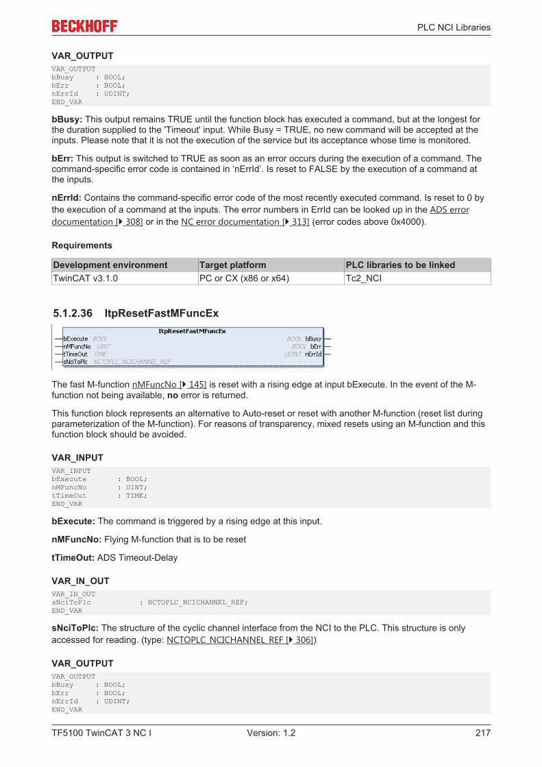
PLC NCI Libraries
TF5100 TwinCAT 3 NC I 217Version: 1.2
VAR_OUTPUTVAR_OUTPUTbBusy : BOOL;bErr : BOOL;nErrId : UDINT;END_VAR
bBusy: This output remains TRUE until the function block has executed a command, but at the longest forthe duration supplied to the 'Timeout' input. While Busy = TRUE, no new command will be accepted at theinputs. Please note that it is not the execution of the service but its acceptance whose time is monitored.
bErr: This output is switched to TRUE as soon as an error occurs during the execution of a command. Thecommand-specific error code is contained in ‘nErrId’. Is reset to FALSE by the execution of a command atthe inputs.
nErrId: Contains the command-specific error code of the most recently executed command. Is reset to 0 bythe execution of a command at the inputs. The error numbers in ErrId can be looked up in the ADS errordocumentation [} 308] or in the NC error documentation [} 313] (error codes above 0x4000).
Requirements
Development environment Target platform PLC libraries to be linkedTwinCAT v3.1.0 PC or CX (x86 or x64) Tc2_NCI
5.1.2.36 ItpResetFastMFuncEx
The fast M-function nMFuncNo [} 145] is reset with a rising edge at input bExecute. In the event of the M-function not being available, no error is returned.
This function block represents an alternative to Auto-reset or reset with another M-function (reset list duringparameterization of the M-function). For reasons of transparency, mixed resets using an M-function and thisfunction block should be avoided.
VAR_INPUTVAR_INPUTbExecute : BOOL;nMFuncNo : UINT; tTimeOut : TIME;END_VAR
bExecute: The command is triggered by a rising edge at this input.
nMFuncNo: Flying M-function that is to be reset
tTimeOut: ADS Timeout-Delay
VAR_IN_OUTVAR_IN_OUTsNciToPlc : NCTOPLC_NCICHANNEL_REF;END_VAR
sNciToPlc: The structure of the cyclic channel interface from the NCI to the PLC. This structure is onlyaccessed for reading. (type: NCTOPLC_NCICHANNEL_REF [} 306])
VAR_OUTPUTVAR_OUTPUTbBusy : BOOL;bErr : BOOL;nErrId : UDINT;END_VAR
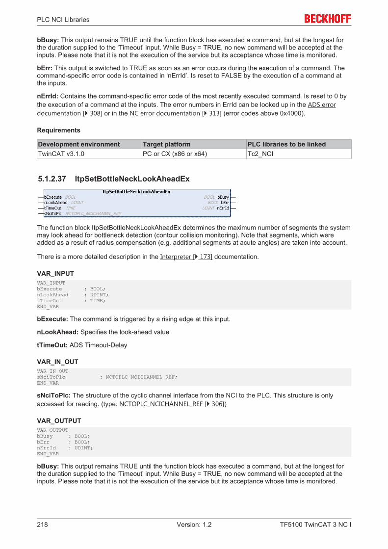
PLC NCI Libraries
TF5100 TwinCAT 3 NC I218 Version: 1.2
bBusy: This output remains TRUE until the function block has executed a command, but at the longest forthe duration supplied to the 'Timeout' input. While Busy = TRUE, no new command will be accepted at theinputs. Please note that it is not the execution of the service but its acceptance whose time is monitored.
bErr: This output is switched to TRUE as soon as an error occurs during the execution of a command. Thecommand-specific error code is contained in ‘nErrId’. Is reset to FALSE by the execution of a command atthe inputs.
nErrId: Contains the command-specific error code of the most recently executed command. Is reset to 0 bythe execution of a command at the inputs. The error numbers in ErrId can be looked up in the ADS errordocumentation [} 308] or in the NC error documentation [} 313] (error codes above 0x4000).
Requirements
Development environment Target platform PLC libraries to be linkedTwinCAT v3.1.0 PC or CX (x86 or x64) Tc2_NCI
5.1.2.37 ItpSetBottleNeckLookAheadEx
The function block ItpSetBottleNeckLookAheadEx determines the maximum number of segments the systemmay look ahead for bottleneck detection (contour collision monitoring). Note that segments, which wereadded as a result of radius compensation (e.g. additional segments at acute angles) are taken into account.
There is a more detailed description in the Interpreter [} 173] documentation.
VAR_INPUTVAR_INPUTbExecute : BOOL;nLookAhead : UDINT;tTimeOut : TIME;END_VAR
bExecute: The command is triggered by a rising edge at this input.
nLookAhead: Specifies the look-ahead value
tTimeOut: ADS Timeout-Delay
VAR_IN_OUTVAR_IN_OUTsNciToPlc : NCTOPLC_NCICHANNEL_REF;END_VAR
sNciToPlc: The structure of the cyclic channel interface from the NCI to the PLC. This structure is onlyaccessed for reading. (type: NCTOPLC_NCICHANNEL_REF [} 306])
VAR_OUTPUTVAR_OUTPUTbBusy : BOOL;bErr : BOOL;nErrId : UDINT;END_VAR
bBusy: This output remains TRUE until the function block has executed a command, but at the longest forthe duration supplied to the 'Timeout' input. While Busy = TRUE, no new command will be accepted at theinputs. Please note that it is not the execution of the service but its acceptance whose time is monitored.
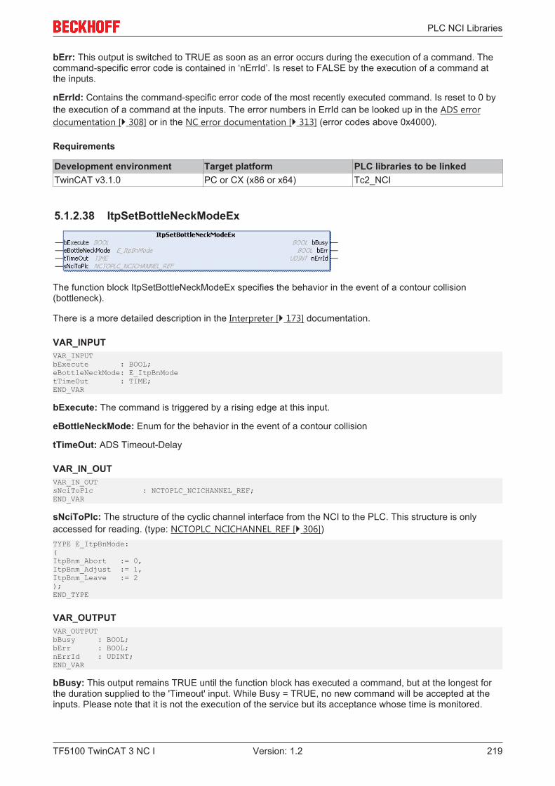
PLC NCI Libraries
TF5100 TwinCAT 3 NC I 219Version: 1.2
bErr: This output is switched to TRUE as soon as an error occurs during the execution of a command. Thecommand-specific error code is contained in ‘nErrId’. Is reset to FALSE by the execution of a command atthe inputs.
nErrId: Contains the command-specific error code of the most recently executed command. Is reset to 0 bythe execution of a command at the inputs. The error numbers in ErrId can be looked up in the ADS errordocumentation [} 308] or in the NC error documentation [} 313] (error codes above 0x4000).
Requirements
Development environment Target platform PLC libraries to be linkedTwinCAT v3.1.0 PC or CX (x86 or x64) Tc2_NCI
5.1.2.38 ItpSetBottleNeckModeEx
The function block ItpSetBottleNeckModeEx specifies the behavior in the event of a contour collision(bottleneck).
There is a more detailed description in the Interpreter [} 173] documentation.
VAR_INPUTVAR_INPUTbExecute : BOOL;eBottleNeckMode: E_ItpBnModetTimeOut : TIME;END_VAR
bExecute: The command is triggered by a rising edge at this input.
eBottleNeckMode: Enum for the behavior in the event of a contour collision
tTimeOut: ADS Timeout-Delay
VAR_IN_OUTVAR_IN_OUTsNciToPlc : NCTOPLC_NCICHANNEL_REF;END_VAR
sNciToPlc: The structure of the cyclic channel interface from the NCI to the PLC. This structure is onlyaccessed for reading. (type: NCTOPLC_NCICHANNEL_REF [} 306])TYPE E_ItpBnMode: (ItpBnm_Abort := 0,ItpBnm_Adjust := 1,ItpBnm_Leave := 2);END_TYPE
VAR_OUTPUTVAR_OUTPUTbBusy : BOOL;bErr : BOOL;nErrId : UDINT;END_VAR
bBusy: This output remains TRUE until the function block has executed a command, but at the longest forthe duration supplied to the 'Timeout' input. While Busy = TRUE, no new command will be accepted at theinputs. Please note that it is not the execution of the service but its acceptance whose time is monitored.
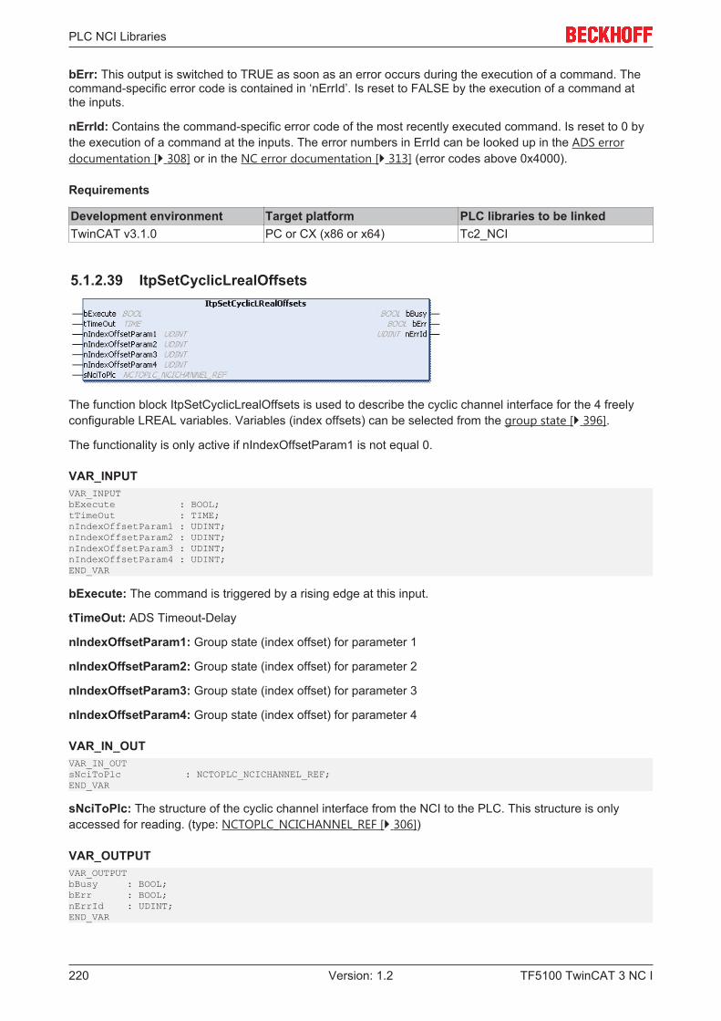
PLC NCI Libraries
TF5100 TwinCAT 3 NC I220 Version: 1.2
bErr: This output is switched to TRUE as soon as an error occurs during the execution of a command. Thecommand-specific error code is contained in ‘nErrId’. Is reset to FALSE by the execution of a command atthe inputs.
nErrId: Contains the command-specific error code of the most recently executed command. Is reset to 0 bythe execution of a command at the inputs. The error numbers in ErrId can be looked up in the ADS errordocumentation [} 308] or in the NC error documentation [} 313] (error codes above 0x4000).
Requirements
Development environment Target platform PLC libraries to be linkedTwinCAT v3.1.0 PC or CX (x86 or x64) Tc2_NCI
5.1.2.39 ItpSetCyclicLrealOffsets
The function block ItpSetCyclicLrealOffsets is used to describe the cyclic channel interface for the 4 freelyconfigurable LREAL variables. Variables (index offsets) can be selected from the group state [} 396].
The functionality is only active if nIndexOffsetParam1 is not equal 0.
VAR_INPUTVAR_INPUTbExecute : BOOL;tTimeOut : TIME;nIndexOffsetParam1 : UDINT;nIndexOffsetParam2 : UDINT;nIndexOffsetParam3 : UDINT;nIndexOffsetParam4 : UDINT;END_VAR
bExecute: The command is triggered by a rising edge at this input.
tTimeOut: ADS Timeout-Delay
nIndexOffsetParam1: Group state (index offset) for parameter 1
nIndexOffsetParam2: Group state (index offset) for parameter 2
nIndexOffsetParam3: Group state (index offset) for parameter 3
nIndexOffsetParam4: Group state (index offset) for parameter 4
VAR_IN_OUTVAR_IN_OUTsNciToPlc : NCTOPLC_NCICHANNEL_REF;END_VAR
sNciToPlc: The structure of the cyclic channel interface from the NCI to the PLC. This structure is onlyaccessed for reading. (type: NCTOPLC_NCICHANNEL_REF [} 306])
VAR_OUTPUTVAR_OUTPUTbBusy : BOOL;bErr : BOOL;nErrId : UDINT;END_VAR
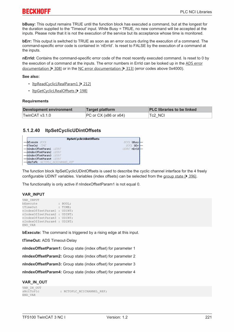
PLC NCI Libraries
TF5100 TwinCAT 3 NC I 221Version: 1.2
bBusy: This output remains TRUE until the function block has executed a command, but at the longest forthe duration supplied to the 'Timeout' input. While Busy = TRUE, no new command will be accepted at theinputs. Please note that it is not the execution of the service but its acceptance whose time is monitored.
bErr: This output is switched to TRUE as soon as an error occurs during the execution of a command. Thecommand-specific error code is contained in ‘nErrId’. Is reset to FALSE by the execution of a command atthe inputs.
nErrId: Contains the command-specific error code of the most recently executed command. Is reset to 0 bythe execution of a command at the inputs. The error numbers in ErrId can be looked up in the ADS errordocumentation [} 308] or in the NC error documentation [} 313] (error codes above 0x4000).
See also:
• ItpReadCyclicLRealParam1 [} 212]
• ItpGetCyclicLRealOffsets [} 198]
Requirements
Development environment Target platform PLC libraries to be linkedTwinCAT v3.1.0 PC or CX (x86 or x64) Tc2_NCI
5.1.2.40 ItpSetCyclicUDintOffsets
The function block ItpSetCyclicUDintOffsets is used to describe the cyclic channel interface for the 4 freelyconfigurable UDINT variables. Variables (index offsets) can be selected from the group state [} 396].
The functionality is only active if nIndexOffsetParam1 is not equal 0.
VAR_INPUTVAR_INPUTbExecute : BOOL;tTimeOut : TIME;nIndexOffsetParam1 : UDINT;nIndexOffsetParam2 : UDINT;nIndexOffsetParam3 : UDINT;nIndexOffsetParam4 : UDINT;END_VAR
bExecute: The command is triggered by a rising edge at this input.
tTimeOut: ADS Timeout-Delay
nIndexOffsetParam1: Group state (index offset) for parameter 1
nIndexOffsetParam2: Group state (index offset) for parameter 2
nIndexOffsetParam3: Group state (index offset) for parameter 3
nIndexOffsetParam4: Group state (index offset) for parameter 4
VAR_IN_OUTVAR_IN_OUTsNciToPlc : NCTOPLC_NCICHANNEL_REF;END_VAR

PLC NCI Libraries
TF5100 TwinCAT 3 NC I222 Version: 1.2
sNciToPlc: The structure of the cyclic channel interface from the NCI to the PLC. This structure is onlyaccessed for reading. (type: NCTOPLC_NCICHANNEL_REF [} 306])
VAR_OUTPUTVAR_OUTPUTbBusy : BOOL;bErr : BOOL;nErrId : UDINT;END_VAR
bBusy: This output remains TRUE until the function block has executed a command, but at the longest forthe duration supplied to the 'Timeout' input. While Busy = TRUE, no new command will be accepted at theinputs. Please note that it is not the execution of the service but its acceptance whose time is monitored.
bErr: This output is switched to TRUE as soon as an error occurs during the execution of a command. Thecommand-specific error code is contained in ‘nErrId’. Is reset to FALSE by the execution of a command atthe inputs.
nErrId: Contains the command-specific error code of the most recently executed command. Is reset to 0 bythe execution of a command at the inputs. The error numbers in ErrId can be looked up in the ADS errordocumentation [} 308] or in the NC error documentation [} 313] (error codes above 0x4000).
See also:
• ItpReadCyclicUDintParam1 [} 212]
• ItpGetCyclicUdintOffsets [} 199]
Requirements
Development environment Target platform PLC libraries to be linkedTwinCAT v3.1.0 PC or CX (x86 or x64) Tc2_NCI
5.1.2.41 ItpSetOverridePercent
The function ItpSetOverridePercent writes the axes channel override into the cyclic interface of the NCI. Theoverride is passed as a percentage.
VAR_INPUTFUNCTION ItpSetOverridePercent
VAR_INPUTfOverridePercent : LREAL;END_VAR
fOverridePercent: Axis channel override as a percentage
VAR_IN_OUTVAR_IN_OUTsPlcToNci : PLCTONC_NCICHANNEL_REF;END_VAR
sPlcToNci: Structure of cyclic channel interface between PLC and NCI (type: PLCTONC_NCICHANNEL_REF[} 308])
Return value
ItpSetOverridePercent: always TRUE

PLC NCI Libraries
TF5100 TwinCAT 3 NC I 223Version: 1.2
SampleVARsPlcToNci AT%Q*: PLCTONC_NCICHANNEL_REF;fOverride : LREAL;END_VAR
fOverride := 47.11;ItpSetOverridePercent( fOverride, sPlcToNci );
Requirements
Development environment Target platform PLC libraries to be linkedTwinCAT v3.1.0 PC or CX (x86 or x64) Tc2_NCI
5.1.2.42 ItpSetSubroutinePathEx
With ItpSetSubroutinePathEx function block, the search path for subroutines can optionally be set.
If a subroutine still has to be integrated, the file is searched in the following order:
1. optional search path (ItpSetSubroutinePath)2. path from which the main program was loaded3. TwinCAT\Mc\Nci directory
Only one optional path can take effect, which remains active until it is overwritten with another path or anempty string.
After a TwinCAT restart, the path has to be re-assigned.
VAR_INPUTVAR_INPUTbExecute : BOOL;sPath : STRING;nLength : UDINT;tTimeOut : TIME;END_VAR
bExecute: The command is triggered by a rising edge at this input.
sPath: Optional path for subroutines. Is deactivated with an empty string
nLength: String length
tTimeOut: ADS Timeout-Delay
VAR_IN_OUTVAR_IN_OUTsNciToPlc : NCTOPLC_NCICHANNEL_REF;END_VAR
sNciToPlc: The structure of the cyclic channel interface from the NCI to the PLC. This structure is onlyaccessed for reading. (type: NCTOPLC_NCICHANNEL_REF [} 306])
VAR_OUTPUTVAR_OUTPUTbBusy : BOOL;bErr : BOOL;nErrId : UDINT;END_VAR

PLC NCI Libraries
TF5100 TwinCAT 3 NC I224 Version: 1.2
bBusy: This output remains TRUE until the function block has executed a command, but at the longest forthe duration supplied to the 'Timeout' input. While Busy = TRUE, no new command will be accepted at theinputs. Please note that it is not the execution of the service but its acceptance whose time is monitored.
bErr: This output is switched to TRUE as soon as an error occurs during the execution of a command. Thecommand-specific error code is contained in ‘nErrId’. Is reset to FALSE by the execution of a command atthe inputs.
nErrId: Contains the command-specific error code of the most recently executed command. Is reset to 0 bythe execution of a command at the inputs. The error numbers in ErrId can be looked up in the ADS errordocumentation [} 308] or in the NC error documentation [} 313] (error codes above 0x4000).
Requirements
Development environment Target platform PLC libraries to be linkedTwinCAT v3.1.0 PC or CX (x86 or x64) Tc2_NCI
5.1.2.43 ItpSetToolDescNullEx
FB ItpSetToolDescNullEx overwrites all tool parameters (incl. number & type) of the channel with zero.
VAR_INPUTVAR_INPUTbExecute : BOOL;tTimeOut : TIME;END_VAR
bExecute: A rising edge results in overwriting of all tool parameters of the NC channel with zero.
VAR_IN_OUTVAR_IN_OUTsNciToPlc : NCTOPLC_NCICHANNEL_REF;END_VAR
sNciToPlc: The structure of the cyclic channel interface from the NCI to the PLC. This structure is onlyaccessed for reading. (type: NCTOPLC_NCICHANNEL_REF [} 306])
VAR_OUTPUTVAR_OUTPUTbBusy : BOOL;bErr : BOOL;nErrId : UDINT;END_VAR
bBusy: This output remains TRUE until the function block has executed a command, but at the longest forthe duration supplied to the 'Timeout' input. While Busy = TRUE, no new command will be accepted at theinputs. Please note that it is not the execution of the service but its acceptance whose time is monitored.
bErr: This output is switched to TRUE as soon as an error occurs during the execution of a command. Thecommand-specific error code is contained in ‘nErrId’. Is reset to FALSE by the execution of a command atthe inputs.
nErrId: Contains the command-specific error code of the most recently executed command. Is reset to 0 bythe execution of a command at the inputs. The error numbers in ErrId can be looked up in the ADS errordocumentation [} 308] or in the NC error documentation [} 313] (error codes above 0x4000).
See also:
ItpWriteToolDescEx [} 230]
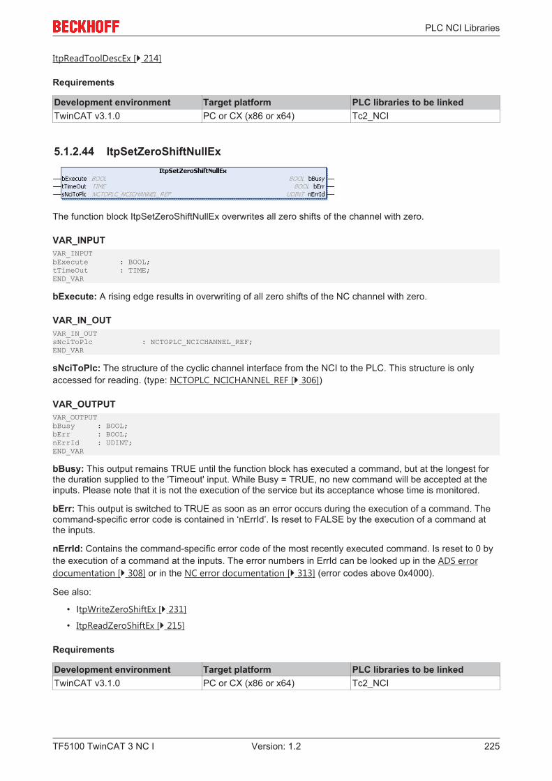
PLC NCI Libraries
TF5100 TwinCAT 3 NC I 225Version: 1.2
ItpReadToolDescEx [} 214]
Requirements
Development environment Target platform PLC libraries to be linkedTwinCAT v3.1.0 PC or CX (x86 or x64) Tc2_NCI
5.1.2.44 ItpSetZeroShiftNullEx
The function block ItpSetZeroShiftNullEx overwrites all zero shifts of the channel with zero.
VAR_INPUTVAR_INPUTbExecute : BOOL;tTimeOut : TIME;END_VAR
bExecute: A rising edge results in overwriting of all zero shifts of the NC channel with zero.
VAR_IN_OUTVAR_IN_OUTsNciToPlc : NCTOPLC_NCICHANNEL_REF;END_VAR
sNciToPlc: The structure of the cyclic channel interface from the NCI to the PLC. This structure is onlyaccessed for reading. (type: NCTOPLC_NCICHANNEL_REF [} 306])
VAR_OUTPUTVAR_OUTPUTbBusy : BOOL;bErr : BOOL;nErrId : UDINT;END_VAR
bBusy: This output remains TRUE until the function block has executed a command, but at the longest forthe duration supplied to the 'Timeout' input. While Busy = TRUE, no new command will be accepted at theinputs. Please note that it is not the execution of the service but its acceptance whose time is monitored.
bErr: This output is switched to TRUE as soon as an error occurs during the execution of a command. Thecommand-specific error code is contained in ‘nErrId’. Is reset to FALSE by the execution of a command atthe inputs.
nErrId: Contains the command-specific error code of the most recently executed command. Is reset to 0 bythe execution of a command at the inputs. The error numbers in ErrId can be looked up in the ADS errordocumentation [} 308] or in the NC error documentation [} 313] (error codes above 0x4000).
See also:
• ItpWriteZeroShiftEx [} 231]
• ItpReadZeroShiftEx [} 215]
Requirements
Development environment Target platform PLC libraries to be linkedTwinCAT v3.1.0 PC or CX (x86 or x64) Tc2_NCI

PLC NCI Libraries
TF5100 TwinCAT 3 NC I226 Version: 1.2
5.1.2.45 ItpSingleBlock
The ItpSingleBlock function block activates or deactivates single block mode in the NCI. Block relaying canbe triggered directly from the PLC with the input 'bTriggerNext'. Alternatively the Start button of theinterpreter (F5) can be used in the XAE .
A more detailed description can be found in the interpreter documentation [} 114].
VAR_INPUTVAR_INPUTbExecuteModeChange : BOOL;nMode : E_ItpSingelBlockMode;bTriggerNext : BOOLtTimeOut : TIME;END_VAR
bExecuteModeChange: Single block mode (nMode) is activated through a rising edge at this input.
nMode: Operation mode for single block (cf. single block mode):
• ItpSingleBlockOff: single block off• ItpSingleBlockNck: single block in NC kernel• ItpSingleBlockIntp: single block in interpreter
bTriggerNext: Block relaying is triggered by a rising edge at this input.
tTimeOut: ADS Timeout-Delay
VAR_IN_OUTVAR_IN_OUTsNciToPlc : NCTOPLC_NCICHANNEL_REF;END_VAR
sNciToPlc: The structure of the cyclic channel interface from the NCI to the PLC. This structure is onlyaccessed for reading. (type: NCTOPLC_NCICHANNEL_REF [} 306])TYPE E_ItpSingleBlockMode:(ItpSingleBlockOff := 0,ItpSingleBlockNck := 1,ItpSingleBlockIntp := 16#4000);END_TYPE
VAR_OUTPUTVAR_OUTPUTbBusy : BOOL;bErr : BOOL;nErrId : UDINT;END_VAR
bBusy: This output remains TRUE until the function block has executed a command, but at the longest forthe duration supplied to the 'Timeout' input. While Busy = TRUE, no new command will be accepted at theinputs. Please note that it is not the execution of the service but its acceptance whose time is monitored.
bErr: This output is switched to TRUE as soon as an error occurs during the execution of a command. Thecommand-specific error code is contained in ‘nErrId’. Is reset to FALSE by the execution of a command atthe inputs.
nErrId: Contains the command-specific error code of the most recently executed command. Is reset to 0 bythe execution of a command at the inputs. The error numbers in ErrId can be looked up in the ADS errordocumentation [} 308] or in the NC error documentation [} 313] (error codes above 0x4000).
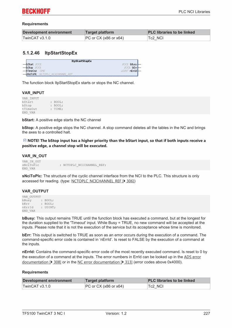
PLC NCI Libraries
TF5100 TwinCAT 3 NC I 227Version: 1.2
Requirements
Development environment Target platform PLC libraries to be linkedTwinCAT v3.1.0 PC or CX (x86 or x64) Tc2_NCI
5.1.2.46 ItpStartStopEx
The function block ItpStartStopEx starts or stops the NC channel.
VAR_INPUTVAR_INPUTbStart : BOOL;bStop : BOOL;tTimeOut : TIME;END_VAR
bStart: A positive edge starts the NC channel
bStop: A positive edge stops the NC channel. A stop command deletes all the tables in the NC and bringsthe axes to a controlled halt.
NOTE! The bStop input has a higher priority than the bStart input, so that if both inputs receive apositive edge, a channel stop will be executed.
VAR_IN_OUTVAR_IN_OUTsNciToPlc : NCTOPLC_NCICHANNEL_REF;END_VAR
sNciToPlc: The structure of the cyclic channel interface from the NCI to the PLC. This structure is onlyaccessed for reading. (type: NCTOPLC_NCICHANNEL_REF [} 306])
VAR_OUTPUTVAR_OUTPUTbBusy : BOOL;bErr : BOOL;nErrId : UDINT;END_VAR
bBusy: This output remains TRUE until the function block has executed a command, but at the longest forthe duration supplied to the 'Timeout' input. While Busy = TRUE, no new command will be accepted at theinputs. Please note that it is not the execution of the service but its acceptance whose time is monitored.
bErr: This output is switched to TRUE as soon as an error occurs during the execution of a command. Thecommand-specific error code is contained in ‘nErrId’. Is reset to FALSE by the execution of a command atthe inputs.
nErrId: Contains the command-specific error code of the most recently executed command. Is reset to 0 bythe execution of a command at the inputs. The error numbers in ErrId can be looked up in the ADS errordocumentation [} 308] or in the NC error documentation [} 313] (error codes above 0x4000).
Requirements
Development environment Target platform PLC libraries to be linkedTwinCAT v3.1.0 PC or CX (x86 or x64) Tc2_NCI
PLC NCI Libraries
TF5100 TwinCAT 3 NC I228 Version: 1.2
5.1.2.47 ItpStepOnAfterEStopEx
The function block ItpStepOnAfterEStopEx enables further processing of the parts program after aprogrammed EStopEx.
VAR_INPUTVAR_INPUTbExecute : BOOL;tTimeOut : TIME;END_VAR
bExecute: The command is triggered by a rising edge at this input.
tTimeOut: ADS Timeout-Delay
VAR_IN_OUTVAR_IN_OUTsNciToPlc : NCTOPLC_NCICHANNEL_REF;END_VAR
sNciToPlc: The structure of the cyclic channel interface from the NCI to the PLC. This structure is onlyaccessed for reading. (type: NCTOPLC_NCICHANNEL_REF [} 306])
VAR_OUTPUTVAR_OUTPUTbBusy : BOOL;bErr : BOOL;nErrId : UDINT;END_VAR
bBusy: This output remains TRUE until the function block has executed a command, but at the longest forthe duration supplied to the 'Timeout' input. While Busy = TRUE, no new command will be accepted at theinputs. Please note that it is not the execution of the service but its acceptance whose time is monitored.
bErr: This output is switched to TRUE as soon as an error occurs during the execution of a command. Thecommand-specific error code is contained in ‘nErrId’. Is reset to FALSE by the execution of a command atthe inputs.
nErrId: Contains the command-specific error code of the most recently executed command. Is reset to 0 bythe execution of a command at the inputs. The error numbers in ErrId can be looked up in the ADS errordocumentation [} 308] or in the NC error documentation [} 313] (error codes above 0x4000).
See also:
ItpEStopEx [} 193]
ItpIsEStopEx [} 209]
Requirements
Development environment Target platform PLC libraries to be linkedTwinCAT v3.1.0 PC or CX (x86 or x64) Tc2_NCI

PLC NCI Libraries
TF5100 TwinCAT 3 NC I 229Version: 1.2
5.1.2.48 ItpWriteRParamsEx
The function block ItpWriteRParamsEx writes R-parameters into the NC.
VAR_INPUT
VAR_INPUTbExecute : BOOL;pAddr : DWORD;nIndex : DINT;nCount : DINT;tTimeOut : TIME;END_VAR
bExecute: A rising edge starts the write operation.
pAddr: Address of the variables containing the data to be written. Data are used directly from the specifiedaddress, i.e. nIndex is not to be interpreted as offset from pAddr. The data are usually read from an array oftype LREAL, which has to be defined by the user.
nIndex: Describes the index of the R-parameter to be written from an NC perspective.
nCount: Number of R-parameters to be written
tTimeOut: ADS Timeout-Delay
VAR_IN_OUTVAR_IN_OUTsNciToPlc : NCTOPLC_NCICHANNEL_REF;END_VAR
sNciToPlc: The structure of the cyclic channel interface from the NCI to the PLC. This structure is onlyaccessed for reading. (type: NCTOPLC_NCICHANNEL_REF [} 306])
VAR_OUTPUTVAR_OUTPUTbBusy : BOOL;bErr : BOOL;nErrId : UDINT;END_VAR
bBusy: This output remains TRUE until the function block has executed a command, but at the longest forthe duration supplied to the 'Timeout' input. While Busy = TRUE, no new command will be accepted at theinputs. Please note that it is not the execution of the service but its acceptance whose time is monitored.
bErr: This output is switched to TRUE as soon as an error occurs during the execution of a command. Thecommand-specific error code is contained in ‘nErrId’. Is reset to FALSE by the execution of a command atthe inputs.
nErrId: Contains the command-specific error code of the most recently executed command. Is reset to 0 bythe execution of a command at the inputs. The error numbers in ErrId can be looked up in the ADS errordocumentation [} 308] or in the NC error documentation [} 313] (error codes above 0x4000).
SampleVARarrfRParam90to99 : ARRAY[0..9] OF LREAL;fbWriteRParamEx : ItpWriteRParamsEx;n : INT := 0;bWriteParam : BOOL := FALSE;sNciToPlc AT%I* : NCTOPLC_NCICHANNEL_REF;END_VAR

PLC NCI Libraries
TF5100 TwinCAT 3 NC I230 Version: 1.2
FOR n:=0 TO 9 DOarrfRParam90to99[n] := 90 + n;END_FOR
fbWriteRParam( bExecute := bWriteParam, pAddr := ADR( arrfRParam90to99[0] ), nIndex := 90, nCount := 10, tTimeOut := T#200ms, sNciToPlc := sNciToPlc );
In this example the parameters R90 to R99 are written from an NC perspective.
Requirements
Development environment Target platform PLC libraries to be linkedTwinCAT v3.1.0 PC or CX (x86 or x64) Tc2_NCI
5.1.2.49 ItpWriteToolDescEx
The function block ItpWriteToolDescEx writes a block of tool parameters.
VAR_INPUTVAR_INPUTbExecute : BOOL;nDNo : UDINT;tTimeOut : TIME;END_VAR
bExecute: The command is triggered by a rising edge at this input.
nDNo: D-word for which the tool parameters are to be read. nDNo can have values between 1 and 255.
tTimeOut: ADS Timeout-Delay
VAR_IN_OUTVAR_IN_OUTsNciToPlc : NCTOPLC_NCICHANNEL_REF;sToolDesc : ToolDesc;END_VAR
sNciToPlc: The structure of the cyclic channel interface from the NCI to the PLC. This structure is onlyaccessed for reading. (type: NCTOPLC_NCICHANNEL_REF [} 306])
sToolDesc: The structure that contains the new tool parameters. This structure is only accessed for reading.The meaning of the parameters depends on the tool type, and can be found in the tool data [} 162].TYPE ToolDesc:STRUCTnToolNumber : UDINT; (*valid range from 0 .. 65535*)nToolType : UDINT;fParam : ARRAY [2..15] OF LREAL;END_STRUCTEND_TYPE
VAR_OUTPUTVAR_OUTPUTbBusy : BOOL;bErr : BOOL;nErrId : UDINT;END_VAR
PLC NCI Libraries
TF5100 TwinCAT 3 NC I 231Version: 1.2
bBusy: This output remains TRUE until the function block has executed a command, but at the longest forthe duration supplied to the 'Timeout' input. While Busy = TRUE, no new command will be accepted at theinputs. Please note that it is not the execution of the service but its acceptance whose time is monitored.
bErr: This output is switched to TRUE as soon as an error occurs during the execution of a command. Thecommand-specific error code is contained in ‘nErrId’. Is reset to FALSE by the execution of a command atthe inputs.
nErrId: Contains the command-specific error code of the most recently executed command. Is reset to 0 bythe execution of a command at the inputs. The error numbers in ErrId can be looked up in the ADS errordocumentation [} 308] or in the NC error documentation [} 313] (error codes above 0x4000).
See also:
ItpReadToolDescEx [} 214]
ItpSetToolDescNullEx [} 224]
Requirements
Development environment Target platform PLC libraries to be linkedTwinCAT v3.1.0 PC or CX (x86 or x64) Tc2_NCI
5.1.2.50 ItpWriteZeroShiftEx
The function block ItpWriteZeroShiftEx writes the shift components X, Y and Z for the specified zero shift.
VAR_INPUTVAR_INPUTbExecute : BOOL;nZsNo : UDINT;tTimeOut : TIME;END_VAR
bExecute: The command is triggered by a rising edge at this input.
nZsNo: Number of the zero shift.
G54 to G59 are zero shifts at the NC. G58 and G59 can only be edited from the NC program. The validrange of values for 'nZsNo' is therefore from 54 to 57.
tTimeOut: ADS Timeout-Delay
VAR_IN_OUTVAR_IN_OUTsNciToPlc AT%I*: NCTOPLC_NCICHANNEL_REF;sZeroShiftDesc : ZeroShiftDesc;END_VAR
sNciToPlc: The structure of the cyclic channel interface from the NCI to the PLC. This structure is onlyaccessed for reading. (type: NCTOPLC_NCICHANNEL_REF [} 306])
sZeroShiftDesc: The structure containing the components of the zero shift. This structure is only accessedfor reading.TYPE ZeroShiftDesc:STRUCTfShiftX : LREAL;fShiftY : LREAL;
PLC NCI Libraries
TF5100 TwinCAT 3 NC I232 Version: 1.2
fShiftZ : LREAL;END_STRUCTEND_TYPE
VAR_OUTPUTVAR_OUTPUTbBusy : BOOL;bErr : BOOL;nErrId : UDINT;END_VAR
bBusy: This output remains TRUE until the function block has executed a command, but at the longest forthe duration supplied to the 'Timeout' input. While Busy = TRUE, no new command will be accepted at theinputs. Please note that it is not the execution of the service but its acceptance whose time is monitored.
bErr: This output is switched to TRUE as soon as an error occurs during the execution of a command. Thecommand-specific error code is contained in ‘nErrId’. Is reset to FALSE by the execution of a command atthe inputs.
nErrId: Contains the command-specific error code of the most recently executed command. Is reset to 0 bythe execution of a command at the inputs. The error numbers in ErrId can be looked up in the ADS errordocumentation [} 308] or in the NC error documentation [} 313] (error codes above 0x4000).
NOTE! For reasons of compatibility every zero shift that can be set has two parameters (coarse andfine) for each axis. When using this function block to write a new zero shift, the new value is writteninto the 'fine parameter'. A value of 0.0 is entered into the 'coarse parameter'.
This makes it possible to use a function block such as ItpReadZeroShiftEx [} 215] to read and modify a zeroshift and to send it back to the NC.
See also:
• ItpReadZeroShiftEx [} 215];
• ItpSetZeroShiftNullEx [} 225]
Requirements
Development environment Target platform PLC libraries to be linkedTwinCAT v3.1.0 PC or CX (x86 or x64) Tc2_NCI
5.1.2.51 Blocksearch
Block search can be used to interrupt a program for a tool change or at the end of a shift. After theinterruption the program can continue at the previous position.
The diagram illustrates how the block search is used.

PLC NCI Libraries
TF5100 TwinCAT 3 NC I 233Version: 1.2
5.1.2.51.1 ItpBlocksearch
The function block ItpBlocksearch sets the interpreter to the point defined at the inputs. The input values canbe taken from function block ItpGetBlocksearchData [} 236] or set manually. Once the interpreter has beenset to the defined location with ItpBlocksearch, the motion can continue with ItpStepOnAfterBlocksearch[} 237] at the position indicated at output sStartPosition.
VAR_INPUTVAR_INPUTbExecute : BOOL;nBlockId : UDINT;eBlockSearchMode : E_ItpBlockSearchMode;eDryRunMode : E_ItpDryRunMode;fLength : LREAL;sPrgName : STRING(255);nPrgLength : UDINT;tTimeOut : TIME;sAxesList : ST_ItpAxes;sOptions : ST_ItpBlockSearchOptions;END_VAR
bExecute: The command is triggered by a rising edge at this input.
nBlockId: Block number or EntryCounter of the segment in the NC program used as starting point.
eBlockSearchMode: Defines whether the specified nBlockId is a block number (e.g. N4711) or continuousEntryCounter. A prerequisite for using the block number is that it is unique. See E_ItpBlockSearchMode[} 234]
eDryRunMode: Defines which program lines are executed and which are skipped. See E_ItpDryRunMode[} 234]
PLC NCI Libraries
TF5100 TwinCAT 3 NC I234 Version: 1.2
fLength: Remaining length within the segment selected with nBlockId in percent.
sPrgName: Name or path of the program to be executed.
nPrgLength: Indicates the length of string sPrgName.
tTimeOut: ADS timeout delay
sAxesList: Definition of the axes in the NCI group. See ST_ItpAxes [} 235]
sOptions: Provides information on retrace.
VAR_IN_OUTVAR_IN_OUTsNciToPlc : NCTOPLC_NCICHANNEL_REF;END_VAR
sNciToPlc: The structure of the cyclic channel interface from the NCI to the PLC. This structure is onlyaccessed for reading. (type: NCTOPLC_NCICHANNEL_REF [} 306])
VAR_OUTPUTVAR_OUTPUTbBusy : BOOL;bErr : BOOL;nErrId : UDINT;bDone : BOOL;sStartPosition : ST_ItpBlockSearchStartPosition;END_VAR
bBusy: Remains TRUE until the function block has executed a command request, but no longer than thetime specified at the 'Timeout' input. While Busy = TRUE, no new command will be accepted at the inputs.
bErr: Becomes TRUE if an error occurs during command execution. The command-specific error code iscontained in ‘nErrId’. Is reset to FALSE by the execution of a command at the inputs.
nErrId: Contains the command-specific error code of the most recently executed command. Is reset to 0 bythe execution of a command at the inputs. The error numbers in ErrId can be looked up in the ADS errordocumentation [} 308] or in the NC error documentation [} 313] (error codes above 0x4000).
bDone: The output becomes TRUE when the command was executed successfully.
sStartPosition: Indicates the start position from which the NC program continues. The individual axesshould be moved to this position before ItpStepOnAfterBlocksearch [} 237] is executed. SeeST_ItpBlockSearchStartPosition [} 235]
E_ItpBlockSearchMode
E_ItpBlockSearchMode is used to define in which way the block search is executed.TYPE E_ItpBlockSearchMode :(ItpBlockSearchMode_Disable := 0,ItpBlockSearchMode_BlockNo := 1,ItpBlockSearchMode_EntryCounter := 2);END_TYPE
ItpBlockSearchMode_Disable: Block search disabled (initial value).
ItpBlockSearchMode_BlockNo: The block search is executed via the block number (e.g. N4711)programmed by the user in the NC program. A prerequisite is that the user-defined block number is unique.
ItpBlockSearchMode_EntryCounter: The block search is executed via a unique EntryCounter. ThisEntryCounter is implicitly unique, but it is not visible to the user in the NC program.
E_ItpDryRunMode
E_ItpDryRunMode defines how blocks are handled, which are located before the block in which the blocksearch is started, when the program is executed.
PLC NCI Libraries
TF5100 TwinCAT 3 NC I 235Version: 1.2
TYPE E_ItpDryRunMode :(ItpDryRunMode_Disable := 0,ItpDryRunMode_SkipAll := 1,ItpDryRunMode_SkipMotionOnly := 2,ItpDryRunMode_SkipDwellAndMotion := 3);END_TYPE
ItpDryRunMode_Disable: DryRun disabled (initial value).
ItpDryRunMode_SkipAll: All previous blocks are skipped. R-parameters are written.
ItpDryRunMode_SkipMotionOnly: Only movement blocks are skipped. R-parameters are written, and dwelltimes and M-functions are executed.
ItpDryRunMode_SkipDwellAndMotion: Movement blocks and dwell times are skipped. R-parameters arewritten and M-functions are executed.
ST_ItpAxes
The structure ST_ItpAxes contains the axes that were in the NCI group during program execution.TYPE ST_ItpAxes :STRUCTnAxisIds : ARRAY[1..8] OF UDINT;END_STRUCTEND_TYPE
nAxisIds: Array of axes that were in the NCI group. The order is nAxisIds[1]=X, nAxisIds[2]=Y,nAxisIds[3]=Z, nAxisIds[4]=Q1, nAxisIds[5]=Q2… The axis ID can be read from the cyclic axis interface.
St_ItpBlockSearchOptions
The structure contains information on the retrace functionality.TYPE ST_ItpBlockSearchOptions :STRUCTbIsRetrace : BOOL:= FALSE;bRetraceBackward : BOOL:= FALSE;END_STRUCTEND_TYPE
bIsRetrace: Indicates whether the retrace functionality is active.
bRetraceBackward: Indicates whether backward movement took place on the path.
ST_ItpBlockSearchStartPosition
The structure indicates the position at which the NC program continues after a block search. The user isresponsible for moving the axes to the corresponding positions.TYPE ST_ItpBlockSearchStartPosition :STRUCTfStartPosition : ARRAY[1..8] OF LREAL;END_STRUCTEND_TYPE
fStartPosition: Array of axis positions at which the NC program continues.
The order is fStartPosition[1]=X, fStartPosition [2]=Y, fStartPosition [3]=Z, fStartPosition [4]=Q1,fStartPosition [5]=Q2…
Requirements
Development environment Target platform PLC libraries to be linkedTwinCAT v3.1.0 PC or CX (x86 or x64) Tc2_NCI
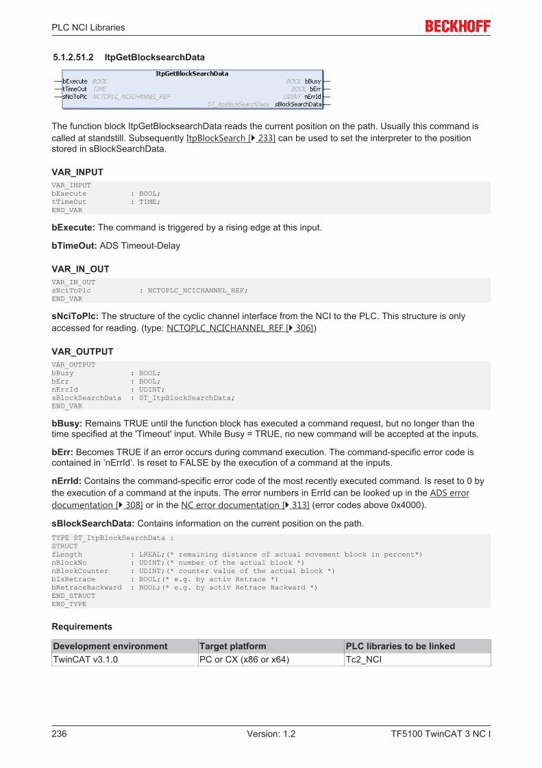
PLC NCI Libraries
TF5100 TwinCAT 3 NC I236 Version: 1.2
5.1.2.51.2 ItpGetBlocksearchData
The function block ItpGetBlocksearchData reads the current position on the path. Usually this command iscalled at standstill. Subsequently ItpBlockSearch [} 233] can be used to set the interpreter to the positionstored in sBlockSearchData.
VAR_INPUTVAR_INPUTbExecute : BOOL;tTimeOut : TIME;END_VAR
bExecute: The command is triggered by a rising edge at this input.
bTimeOut: ADS Timeout-Delay
VAR_IN_OUTVAR_IN_OUTsNciToPlc : NCTOPLC_NCICHANNEL_REF;END_VAR
sNciToPlc: The structure of the cyclic channel interface from the NCI to the PLC. This structure is onlyaccessed for reading. (type: NCTOPLC_NCICHANNEL_REF [} 306])
VAR_OUTPUTVAR_OUTPUTbBusy : BOOL;bErr : BOOL;nErrId : UDINT;sBlockSearchData : ST_ItpBlockSearchData;END_VAR
bBusy: Remains TRUE until the function block has executed a command request, but no longer than thetime specified at the 'Timeout' input. While Busy = TRUE, no new command will be accepted at the inputs.
bErr: Becomes TRUE if an error occurs during command execution. The command-specific error code iscontained in ‘nErrId’. Is reset to FALSE by the execution of a command at the inputs.
nErrId: Contains the command-specific error code of the most recently executed command. Is reset to 0 bythe execution of a command at the inputs. The error numbers in ErrId can be looked up in the ADS errordocumentation [} 308] or in the NC error documentation [} 313] (error codes above 0x4000).
sBlockSearchData: Contains information on the current position on the path.TYPE ST_ItpBlockSearchData :STRUCTfLength : LREAL;(* remaining distance of actual movement block in percent*)nBlockNo : UDINT;(* number of the actual block *)nBlockCounter : UDINT;(* counter value of the actual block *)bIsRetrace : BOOL;(* e.g. by activ Retrace *)bRetraceBackward : BOOL;(* e.g. by activ Retrace Backward *)END_STRUCTEND_TYPE
Requirements
Development environment Target platform PLC libraries to be linkedTwinCAT v3.1.0 PC or CX (x86 or x64) Tc2_NCI
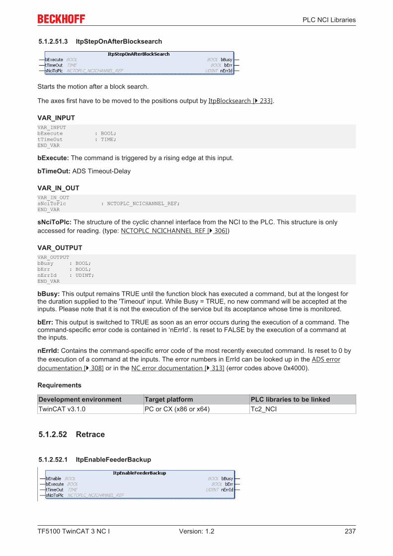
PLC NCI Libraries
TF5100 TwinCAT 3 NC I 237Version: 1.2
5.1.2.51.3 ItpStepOnAfterBlocksearch
Starts the motion after a block search.
The axes first have to be moved to the positions output by ItpBlocksearch [} 233].
VAR_INPUTVAR_INPUTbExecute : BOOL;tTimeOut : TIME;END_VAR
bExecute: The command is triggered by a rising edge at this input.
bTimeOut: ADS Timeout-Delay
VAR_IN_OUTVAR_IN_OUTsNciToPlc : NCTOPLC_NCICHANNEL_REF;END_VAR
sNciToPlc: The structure of the cyclic channel interface from the NCI to the PLC. This structure is onlyaccessed for reading. (type: NCTOPLC_NCICHANNEL_REF [} 306])
VAR_OUTPUTVAR_OUTPUTbBusy : BOOL;bErr : BOOL;nErrId : UDINT;END_VAR
bBusy: This output remains TRUE until the function block has executed a command, but at the longest forthe duration supplied to the 'Timeout' input. While Busy = TRUE, no new command will be accepted at theinputs. Please note that it is not the execution of the service but its acceptance whose time is monitored.
bErr: This output is switched to TRUE as soon as an error occurs during the execution of a command. Thecommand-specific error code is contained in ‘nErrId’. Is reset to FALSE by the execution of a command atthe inputs.
nErrId: Contains the command-specific error code of the most recently executed command. Is reset to 0 bythe execution of a command at the inputs. The error numbers in ErrId can be looked up in the ADS errordocumentation [} 308] or in the NC error documentation [} 313] (error codes above 0x4000).
Requirements
Development environment Target platform PLC libraries to be linkedTwinCAT v3.1.0 PC or CX (x86 or x64) Tc2_NCI
5.1.2.52 Retrace
5.1.2.52.1 ItpEnableFeederBackup
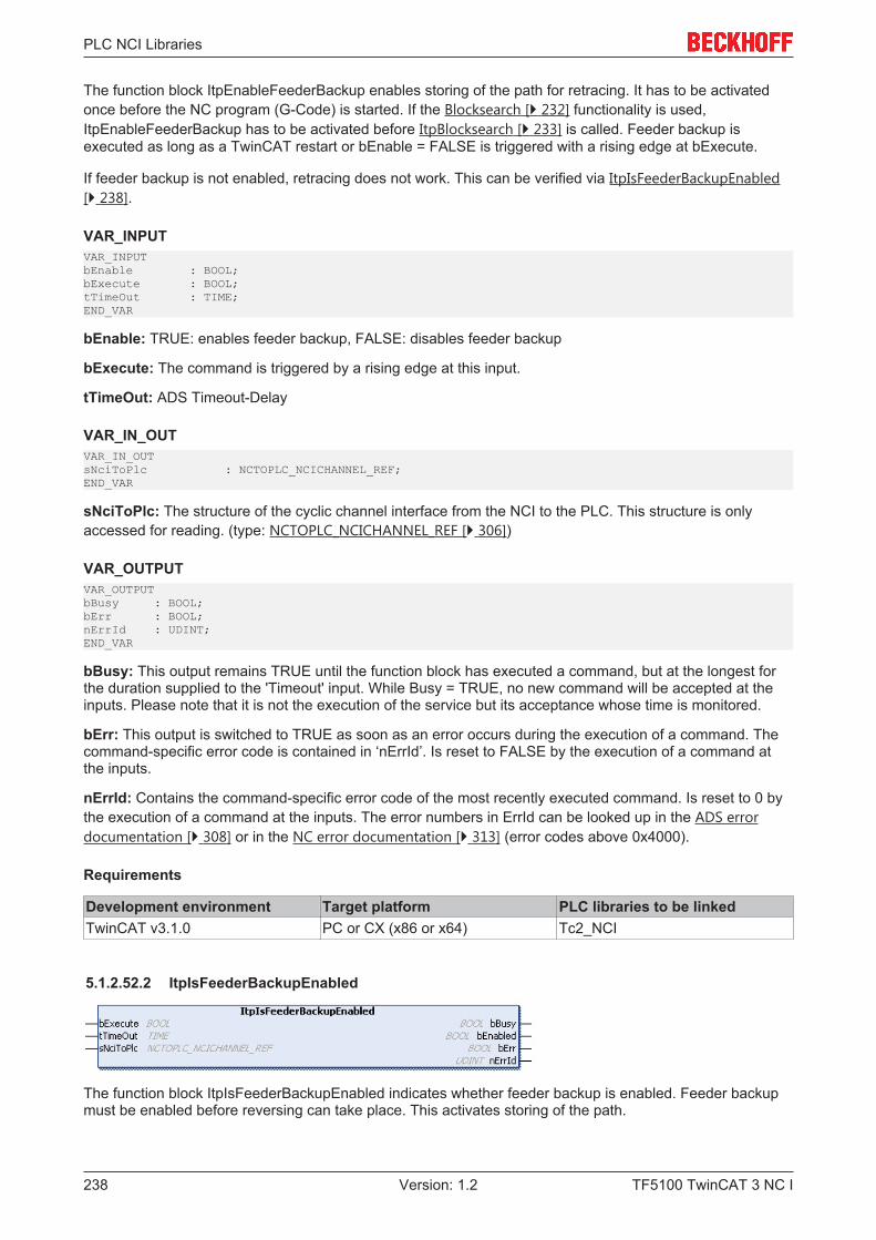
PLC NCI Libraries
TF5100 TwinCAT 3 NC I238 Version: 1.2
The function block ItpEnableFeederBackup enables storing of the path for retracing. It has to be activatedonce before the NC program (G-Code) is started. If the Blocksearch [} 232] functionality is used,ItpEnableFeederBackup has to be activated before ItpBlocksearch [} 233] is called. Feeder backup isexecuted as long as a TwinCAT restart or bEnable = FALSE is triggered with a rising edge at bExecute.
If feeder backup is not enabled, retracing does not work. This can be verified via ItpIsFeederBackupEnabled[} 238].
VAR_INPUTVAR_INPUTbEnable : BOOL;bExecute : BOOL;tTimeOut : TIME;END_VAR
bEnable: TRUE: enables feeder backup, FALSE: disables feeder backup
bExecute: The command is triggered by a rising edge at this input.
tTimeOut: ADS Timeout-Delay
VAR_IN_OUTVAR_IN_OUTsNciToPlc : NCTOPLC_NCICHANNEL_REF;END_VAR
sNciToPlc: The structure of the cyclic channel interface from the NCI to the PLC. This structure is onlyaccessed for reading. (type: NCTOPLC_NCICHANNEL_REF [} 306])
VAR_OUTPUTVAR_OUTPUTbBusy : BOOL;bErr : BOOL;nErrId : UDINT;END_VAR
bBusy: This output remains TRUE until the function block has executed a command, but at the longest forthe duration supplied to the 'Timeout' input. While Busy = TRUE, no new command will be accepted at theinputs. Please note that it is not the execution of the service but its acceptance whose time is monitored.
bErr: This output is switched to TRUE as soon as an error occurs during the execution of a command. Thecommand-specific error code is contained in ‘nErrId’. Is reset to FALSE by the execution of a command atthe inputs.
nErrId: Contains the command-specific error code of the most recently executed command. Is reset to 0 bythe execution of a command at the inputs. The error numbers in ErrId can be looked up in the ADS errordocumentation [} 308] or in the NC error documentation [} 313] (error codes above 0x4000).
Requirements
Development environment Target platform PLC libraries to be linkedTwinCAT v3.1.0 PC or CX (x86 or x64) Tc2_NCI
5.1.2.52.2 ItpIsFeederBackupEnabled
The function block ItpIsFeederBackupEnabled indicates whether feeder backup is enabled. Feeder backupmust be enabled before reversing can take place. This activates storing of the path.
PLC NCI Libraries
TF5100 TwinCAT 3 NC I 239Version: 1.2
VAR_INPUTVAR_INPUTbExecute : BOOL;tTimeOut : TIME;END_VAR
bExecute: The command is triggered by a rising edge at this input.
tTimeOut: ADS Timeout-Delay
VAR_IN_OUTVAR_IN_OUTsNciToPlc : NCTOPLC_NCICHANNEL_REF;END_VAR
sNciToPlc: The structure of the cyclic channel interface from the NCI to the PLC. This structure is onlyaccessed for reading. (type: NCTOPLC_NCICHANNEL_REF [} 306])
VAR_OUTPUTVAR_OUTPUTbBusy : BOOL;bEnabled : BOOL;bErr : BOOL;nErrId : UDINT;END_VAR
bBusy: The bBusy output remains TRUE until the function block has executed a command, with themaximum duration specified by the time associated with the ‘Timeout’ input. While bBusy = TRUE, no newinstruction will be accepted at the inputs. Please note that it is not the execution of the service but itsacceptance whose time is monitored.
bEnabled: TRUE: Backup list for tracing is enabled, FALSE: Backup list for tracing is disabled
bErr: This output is switched to TRUE as soon as an error occurs during the execution of a command. Thecommand-specific error code is contained in ‘nErrId’. If the function block has a timeout error, ‘Error’ is TRUEand ‘nErrId’ is 1861 (hexadecimal 0x745). Is reset to FALSE by the execution of a command at the inputs.
nErrId: Contains the command-specific error code of the most recently executed command. Is reset to 0 bythe execution of a command at the inputs. The error numbers in ErrId can be looked up in the ADS errordocumentation [} 308] or in the NC error documentation [} 313] (error codes above 0x4000).
Requirements
Development environment Target platform PLC libraries to be linkedTwinCAT v3.1.0 PC or CX (x86 or x64) Tc2_NCI
5.1.2.52.3 ItpIsFeedFromBackupList
The function ItpIsFeedFromBackupList becomes TRUE when the feed entries (SAF & SVB) were sent fromthe backup list. During backward movement all entries are sent from the backup list. If the program isexecuted in forward mode, the first entries usually also originate from the backup list. This is dependent ofthe number of retraced entries and the number of entries in the SVB and SAF tables at the time at whichtracing was called. All further commands originate from the ‚original’ code.
While the NCI is processing the backup list, not all functions are available or meaningful. Here are a fewexamples:
• Decoder stops such as @714 are not evaluated• Modifications of R-parameters do not take effect as long as the motion takes place on the backup path
(forward or backward). R-parameters modifications take effect again as soon as the path data nolonger come from the backup list.
PLC NCI Libraries
TF5100 TwinCAT 3 NC I240 Version: 1.2
VAR_IN_OUTVAR_IN_OUTsNciToPlc : NCTOPLC_NCICHANNEL_REF;END_VAR
sNciToPlc: The structure of the cyclic channel interface from the NCI to the PLC. This structure is onlyaccessed for reading. (type: NCTOPLC_NCICHANNEL_REF [} 306])
Requirements
Development environment Target platform PLC libraries to be linkedTwinCAT v3.1.0 PC or CX (x86 or x64) Tc2_NCI
5.1.2.52.4 ItpIsFirstSegmentReached
ItpIsFirstSegmentReached is a function that determines whether the program start position is reachedduring retracing, based on the cyclic channel interface.
VAR_IN_OUTVAR_IN_OUTsNciToPlc : NCTOPLC_NCICHANNEL_REF;END_VAR
sNciToPlc: The structure of the cyclic channel interface from the NCI to the PLC. This structure is onlyaccessed for reading. (type: NCTOPLC_NCICHANNEL_REF [} 306])
Return value
The function returns TRUE when the start position of the G-Code program is reached. If the version numberof the cyclic channel interface is less than 6, the return value is always FALSE.
Requirements
Development environment Target platform PLC libraries to be linkedTwinCAT v3.1.0 PC or CX (x86 or x64) Tc2_NCI
5.1.2.52.5 ItpIsMovingBackwards
ItpIsMovingBackwards is a function that determines whether backward movement takes place on the pathof the current G-Code program, based on the cyclic channel interface.
VAR_IN_OUTVAR_IN_OUTsNciToPlc : NCTOPLC_NCICHANNEL_REF;END_VAR
sNciToPlc: The structure of the cyclic channel interface from the NCI to the PLC. This structure is onlyaccessed for reading. (type: NCTOPLC_NCICHANNEL_REF [} 306])
Return value
The function returns TRUE when backward movement takes place on the path. If the version number of thecyclic channel interface is less than 6, the return value is always FALSE.
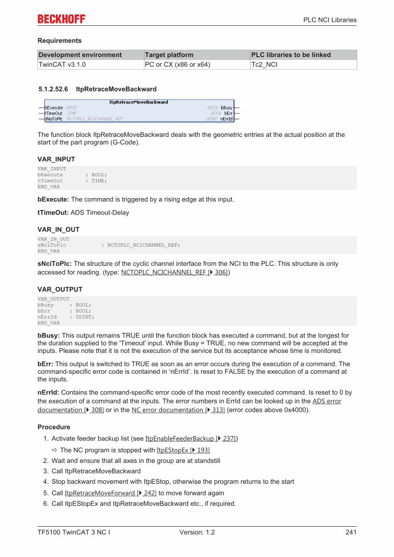
PLC NCI Libraries
TF5100 TwinCAT 3 NC I 241Version: 1.2
Requirements
Development environment Target platform PLC libraries to be linkedTwinCAT v3.1.0 PC or CX (x86 or x64) Tc2_NCI
5.1.2.52.6 ItpRetraceMoveBackward
The function block ItpRetraceMoveBackward deals with the geometric entries at the actual position at thestart of the part program (G-Code).
VAR_INPUTVAR_INPUTbExecute : BOOL;tTimeOut : TIME;END_VAR
bExecute: The command is triggered by a rising edge at this input.
tTimeOut: ADS Timeout-Delay
VAR_IN_OUTVAR_IN_OUTsNciToPlc : NCTOPLC_NCICHANNEL_REF;END_VAR
sNciToPlc: The structure of the cyclic channel interface from the NCI to the PLC. This structure is onlyaccessed for reading. (type: NCTOPLC_NCICHANNEL_REF [} 306])
VAR_OUTPUTVAR_OUTPUTbBusy : BOOL;bErr : BOOL;nErrId : UDINT;END_VAR
bBusy: This output remains TRUE until the function block has executed a command, but at the longest forthe duration supplied to the 'Timeout' input. While Busy = TRUE, no new command will be accepted at theinputs. Please note that it is not the execution of the service but its acceptance whose time is monitored.
bErr: This output is switched to TRUE as soon as an error occurs during the execution of a command. Thecommand-specific error code is contained in ‘nErrId’. Is reset to FALSE by the execution of a command atthe inputs.
nErrId: Contains the command-specific error code of the most recently executed command. Is reset to 0 bythe execution of a command at the inputs. The error numbers in ErrId can be looked up in the ADS errordocumentation [} 308] or in the NC error documentation [} 313] (error codes above 0x4000).
Procedure1. Activate feeder backup list (see ItpEnableFeederBackup [} 237])
ð The NC program is stopped with ItpEStopEx [} 193]2. Wait and ensure that all axes in the group are at standstill3. Call ItpRetraceMoveBackward4. Stop backward movement with ItpEStop, otherwise the program returns to the start
5. Call ItpRetraceMoveForward [} 242] to move forward again6. Call ItpEStopEx and ItpRetraceMoveBackward etc., if required.
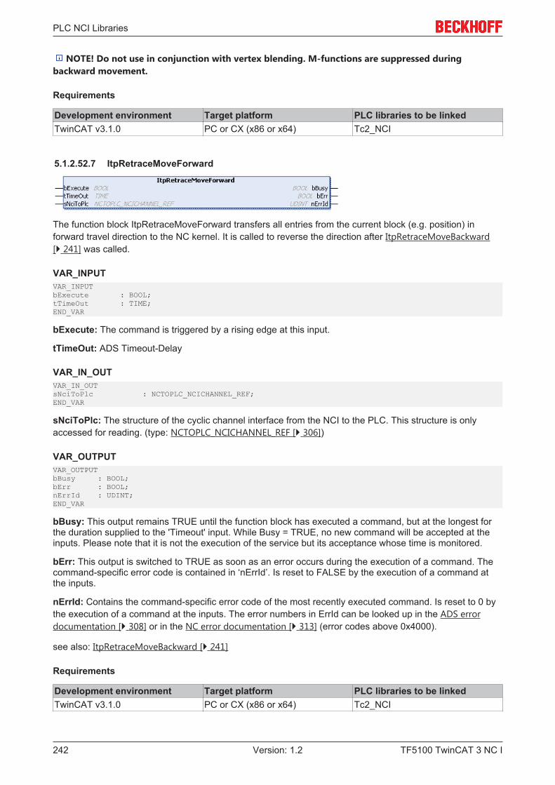
PLC NCI Libraries
TF5100 TwinCAT 3 NC I242 Version: 1.2
NOTE! Do not use in conjunction with vertex blending. M-functions are suppressed duringbackward movement.
Requirements
Development environment Target platform PLC libraries to be linkedTwinCAT v3.1.0 PC or CX (x86 or x64) Tc2_NCI
5.1.2.52.7 ItpRetraceMoveForward
The function block ItpRetraceMoveForward transfers all entries from the current block (e.g. position) inforward travel direction to the NC kernel. It is called to reverse the direction after ItpRetraceMoveBackward[} 241] was called.
VAR_INPUTVAR_INPUTbExecute : BOOL;tTimeOut : TIME;END_VAR
bExecute: The command is triggered by a rising edge at this input.
tTimeOut: ADS Timeout-Delay
VAR_IN_OUTVAR_IN_OUTsNciToPlc : NCTOPLC_NCICHANNEL_REF;END_VAR
sNciToPlc: The structure of the cyclic channel interface from the NCI to the PLC. This structure is onlyaccessed for reading. (type: NCTOPLC_NCICHANNEL_REF [} 306])
VAR_OUTPUTVAR_OUTPUTbBusy : BOOL;bErr : BOOL;nErrId : UDINT;END_VAR
bBusy: This output remains TRUE until the function block has executed a command, but at the longest forthe duration supplied to the 'Timeout' input. While Busy = TRUE, no new command will be accepted at theinputs. Please note that it is not the execution of the service but its acceptance whose time is monitored.
bErr: This output is switched to TRUE as soon as an error occurs during the execution of a command. Thecommand-specific error code is contained in ‘nErrId’. Is reset to FALSE by the execution of a command atthe inputs.
nErrId: Contains the command-specific error code of the most recently executed command. Is reset to 0 bythe execution of a command at the inputs. The error numbers in ErrId can be looked up in the ADS errordocumentation [} 308] or in the NC error documentation [} 313] (error codes above 0x4000).
see also: ItpRetraceMoveBackward [} 241]
Requirements
Development environment Target platform PLC libraries to be linkedTwinCAT v3.1.0 PC or CX (x86 or x64) Tc2_NCI
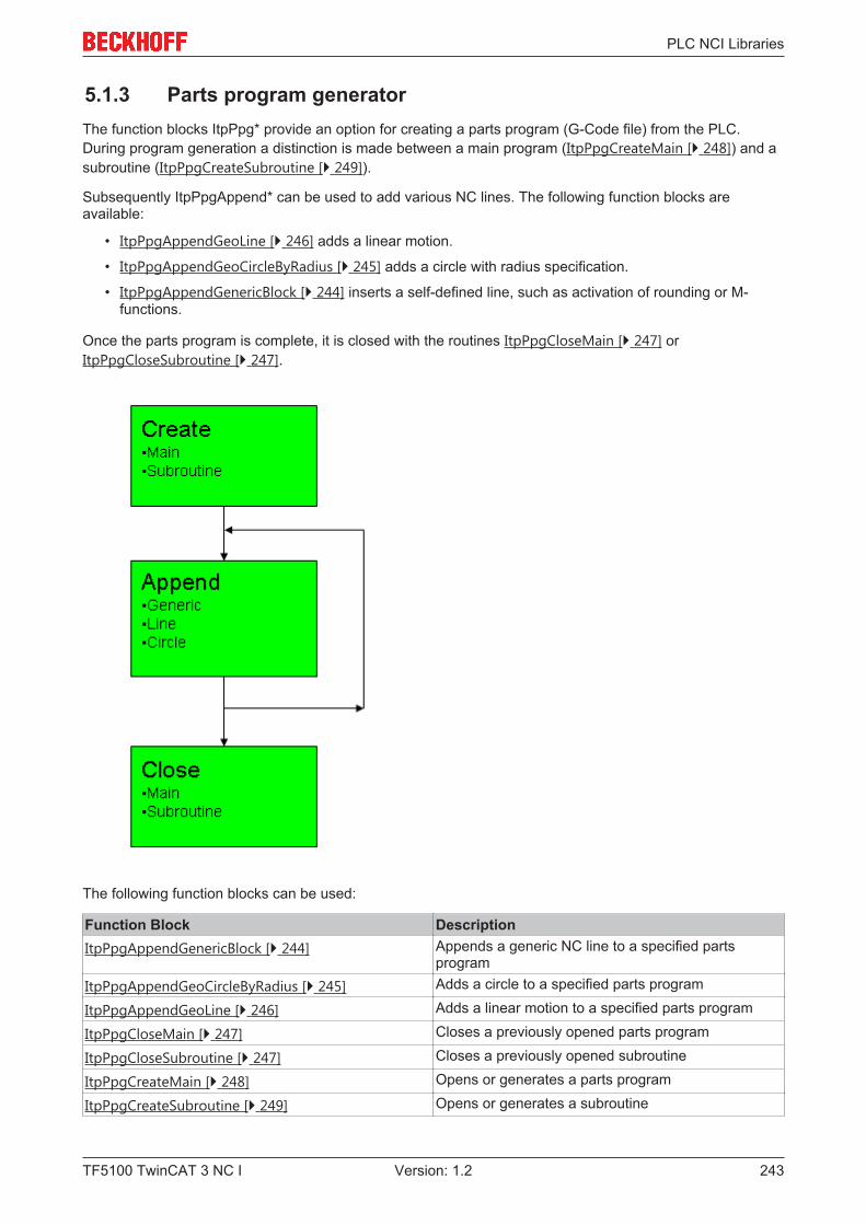
PLC NCI Libraries
TF5100 TwinCAT 3 NC I 243Version: 1.2
5.1.3 Parts program generatorThe function blocks ItpPpg* provide an option for creating a parts program (G-Code file) from the PLC.During program generation a distinction is made between a main program (ItpPpgCreateMain [} 248]) and asubroutine (ItpPpgCreateSubroutine [} 249]).
Subsequently ItpPpgAppend* can be used to add various NC lines. The following function blocks areavailable:
• ItpPpgAppendGeoLine [} 246] adds a linear motion.
• ItpPpgAppendGeoCircleByRadius [} 245] adds a circle with radius specification.
• ItpPpgAppendGenericBlock [} 244] inserts a self-defined line, such as activation of rounding or M-functions.
Once the parts program is complete, it is closed with the routines ItpPpgCloseMain [} 247] orItpPpgCloseSubroutine [} 247].
The following function blocks can be used:
Function Block DescriptionItpPpgAppendGenericBlock [} 244] Appends a generic NC line to a specified parts
programItpPpgAppendGeoCircleByRadius [} 245] Adds a circle to a specified parts program
ItpPpgAppendGeoLine [} 246] Adds a linear motion to a specified parts program
ItpPpgCloseMain [} 247] Closes a previously opened parts program
ItpPpgCloseSubroutine [} 247] Closes a previously opened subroutine
ItpPpgCreateMain [} 248] Opens or generates a parts program
ItpPpgCreateSubroutine [} 249] Opens or generates a subroutine
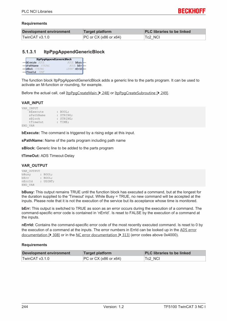
PLC NCI Libraries
TF5100 TwinCAT 3 NC I244 Version: 1.2
Requirements
Development environment Target platform PLC libraries to be linkedTwinCAT v3.1.0 PC or CX (x86 or x64) Tc2_NCI
5.1.3.1 ItpPpgAppendGenericBlock
The function block ItpPpgAppendGenericBlock adds a generic line to the parts program. It can be used toactivate an M-function or rounding, for example.
Before the actual call, call ItpPpgCreateMain [} 248] or ItpPpgCreateSubroutine [} 249].
VAR_INPUTVAR_INPUT bExecute : BOOL; sPathName : STRING; sBlock : STRING; tTimeOut : TIME;END_VAR
bExecute: The command is triggered by a rising edge at this input.
sPathName: Name of the parts program including path name
sBlock: Generic line to be added to the parts program
tTimeOut: ADS Timeout-Delay
VAR_OUTPUTVAR_OUTPUTbBusy : BOOL;bErr : BOOL;nErrId : UDINT;END_VAR
bBusy: This output remains TRUE until the function block has executed a command, but at the longest forthe duration supplied to the 'Timeout' input. While Busy = TRUE, no new command will be accepted at theinputs. Please note that it is not the execution of the service but its acceptance whose time is monitored.
bErr: This output is switched to TRUE as soon as an error occurs during the execution of a command. Thecommand-specific error code is contained in ‘nErrId’. Is reset to FALSE by the execution of a command atthe inputs.
nErrId: Contains the command-specific error code of the most recently executed command. Is reset to 0 bythe execution of a command at the inputs. The error numbers in ErrId can be looked up in the ADS errordocumentation [} 308] or in the NC error documentation [} 313] (error codes above 0x4000).
Requirements
Development environment Target platform PLC libraries to be linkedTwinCAT v3.1.0 PC or CX (x86 or x64) Tc2_NCI
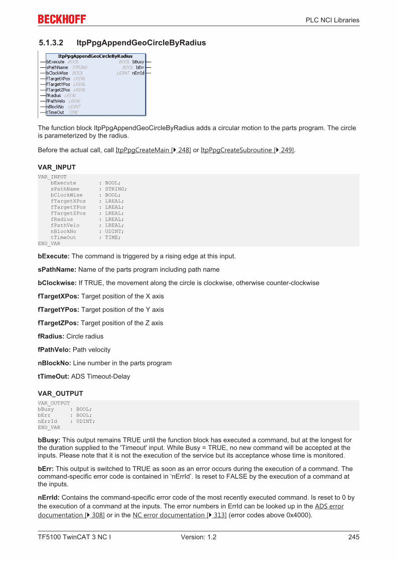
PLC NCI Libraries
TF5100 TwinCAT 3 NC I 245Version: 1.2
5.1.3.2 ItpPpgAppendGeoCircleByRadius
The function block ItpPpgAppendGeoCircleByRadius adds a circular motion to the parts program. The circleis parameterized by the radius.
Before the actual call, call ItpPpgCreateMain [} 248] or ItpPpgCreateSubroutine [} 249].
VAR_INPUTVAR_INPUT bExecute : BOOL; sPathName : STRING; bClockWise : BOOL; fTargetXPos : LREAL; fTargetYPos : LREAL; fTargetZPos : LREAL; fRadius : LREAL; fPathVelo : LREAL; nBlockNo : UDINT; tTimeOut : TIME;END_VAR
bExecute: The command is triggered by a rising edge at this input.
sPathName: Name of the parts program including path name
bClockwise: If TRUE, the movement along the circle is clockwise, otherwise counter-clockwise
fTargetXPos: Target position of the X axis
fTargetYPos: Target position of the Y axis
fTargetZPos: Target position of the Z axis
fRadius: Circle radius
fPathVelo: Path velocity
nBlockNo: Line number in the parts program
tTimeOut: ADS Timeout-Delay
VAR_OUTPUTVAR_OUTPUTbBusy : BOOL;bErr : BOOL;nErrId : UDINT;END_VAR
bBusy: This output remains TRUE until the function block has executed a command, but at the longest forthe duration supplied to the 'Timeout' input. While Busy = TRUE, no new command will be accepted at theinputs. Please note that it is not the execution of the service but its acceptance whose time is monitored.
bErr: This output is switched to TRUE as soon as an error occurs during the execution of a command. Thecommand-specific error code is contained in ‘nErrId’. Is reset to FALSE by the execution of a command atthe inputs.
nErrId: Contains the command-specific error code of the most recently executed command. Is reset to 0 bythe execution of a command at the inputs. The error numbers in ErrId can be looked up in the ADS errordocumentation [} 308] or in the NC error documentation [} 313] (error codes above 0x4000).
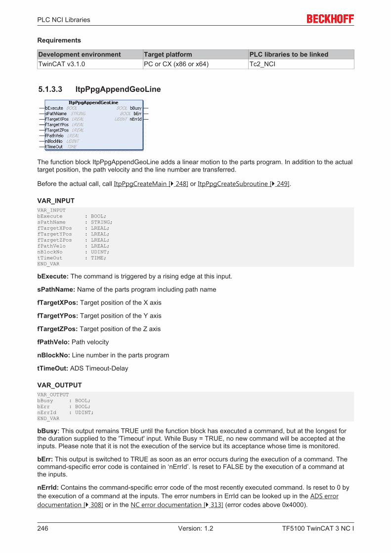
PLC NCI Libraries
TF5100 TwinCAT 3 NC I246 Version: 1.2
Requirements
Development environment Target platform PLC libraries to be linkedTwinCAT v3.1.0 PC or CX (x86 or x64) Tc2_NCI
5.1.3.3 ItpPpgAppendGeoLine
The function block ItpPpgAppendGeoLine adds a linear motion to the parts program. In addition to the actualtarget position, the path velocity and the line number are transferred.
Before the actual call, call ItpPpgCreateMain [} 248] or ItpPpgCreateSubroutine [} 249].
VAR_INPUTVAR_INPUTbExecute : BOOL;sPathName : STRING;fTargetXPos : LREAL;fTargetYPos : LREAL;fTargetZPos : LREAL;fPathVelo : LREAL;nBlockNo : UDINT;tTimeOut : TIME;END_VAR
bExecute: The command is triggered by a rising edge at this input.
sPathName: Name of the parts program including path name
fTargetXPos: Target position of the X axis
fTargetYPos: Target position of the Y axis
fTargetZPos: Target position of the Z axis
fPathVelo: Path velocity
nBlockNo: Line number in the parts program
tTimeOut: ADS Timeout-Delay
VAR_OUTPUTVAR_OUTPUTbBusy : BOOL;bErr : BOOL;nErrId : UDINT;END_VAR
bBusy: This output remains TRUE until the function block has executed a command, but at the longest forthe duration supplied to the 'Timeout' input. While Busy = TRUE, no new command will be accepted at theinputs. Please note that it is not the execution of the service but its acceptance whose time is monitored.
bErr: This output is switched to TRUE as soon as an error occurs during the execution of a command. Thecommand-specific error code is contained in ‘nErrId’. Is reset to FALSE by the execution of a command atthe inputs.
nErrId: Contains the command-specific error code of the most recently executed command. Is reset to 0 bythe execution of a command at the inputs. The error numbers in ErrId can be looked up in the ADS errordocumentation [} 308] or in the NC error documentation [} 313] (error codes above 0x4000).
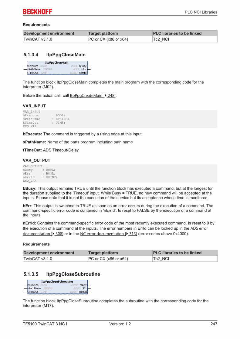
PLC NCI Libraries
TF5100 TwinCAT 3 NC I 247Version: 1.2
Requirements
Development environment Target platform PLC libraries to be linkedTwinCAT v3.1.0 PC or CX (x86 or x64) Tc2_NCI
5.1.3.4 ItpPpgCloseMain
The function block ItpPpgCloseMain completes the main program with the corresponding code for theinterpreter (M02).
Before the actual call, call ItpPpgCreateMain [} 248].
VAR_INPUTVAR_INPUTbExecute : BOOL;sPathName : STRING;tTimeOut : TIME;END_VAR
bExecute: The command is triggered by a rising edge at this input.
sPathName: Name of the parts program including path name
tTimeOut: ADS Timeout-Delay
VAR_OUTPUTVAR_OUTPUTbBusy : BOOL;bErr : BOOL;nErrId : UDINT;END_VAR
bBusy: This output remains TRUE until the function block has executed a command, but at the longest forthe duration supplied to the 'Timeout' input. While Busy = TRUE, no new command will be accepted at theinputs. Please note that it is not the execution of the service but its acceptance whose time is monitored.
bErr: This output is switched to TRUE as soon as an error occurs during the execution of a command. Thecommand-specific error code is contained in ‘nErrId’. Is reset to FALSE by the execution of a command atthe inputs.
nErrId: Contains the command-specific error code of the most recently executed command. Is reset to 0 bythe execution of a command at the inputs. The error numbers in ErrId can be looked up in the ADS errordocumentation [} 308] or in the NC error documentation [} 313] (error codes above 0x4000).
Requirements
Development environment Target platform PLC libraries to be linkedTwinCAT v3.1.0 PC or CX (x86 or x64) Tc2_NCI
5.1.3.5 ItpPpgCloseSubroutine
The function block ItpPpgCloseSubroutine completes the subroutine with the corresponding code for theinterpreter (M17).

PLC NCI Libraries
TF5100 TwinCAT 3 NC I248 Version: 1.2
Before the actual call, call ItpPpgCreateSubroutine [} 249].
VAR_INPUTVAR_INPUTbExecute : BOOL;sPathName : STRING;tTimeOut : TIME;END_VAR
bExecute: The command is triggered by a rising edge at this input.
sPathName: Name of the parts program including path name
tTimeOut: ADS Timeout-Delay
VAR_OUTPUTVAR_OUTPUTbBusy : BOOL;bErr : BOOL;nErrId : UDINT;END_VAR
bBusy: This output remains TRUE until the function block has executed a command, but at the longest forthe duration supplied to the 'Timeout' input. While Busy = TRUE, no new command will be accepted at theinputs. Please note that it is not the execution of the service but its acceptance whose time is monitored.
bErr: This output is switched to TRUE as soon as an error occurs during the execution of a command. Thecommand-specific error code is contained in ‘nErrId’. Is reset to FALSE by the execution of a command atthe inputs.
nErrId: Contains the command-specific error code of the most recently executed command. Is reset to 0 bythe execution of a command at the inputs. The error numbers in ErrId can be looked up in the ADS errordocumentation [} 308] or in the NC error documentation [} 313] (error codes above 0x4000).
Requirements
Development environment Target platform PLC libraries to be linkedTwinCAT v3.1.0 PC or CX (x86 or x64) Tc2_NCI
5.1.3.6 ItpPpgCreateMain
The function block ItpPpgCreateMain generates a new file, which can later be processed as main program. Ifthe file does not yet exist, it is created, otherwise it is overwritten.
VAR_INPUTVAR_INPUTbExecute : BOOL;sPathName : STRING;tTimeOut : TIME;END_VAR
bExecute: The command is triggered by a rising edge at this input.
sPathName: Name of the parts program including path name
tTimeOut: ADS Timeout-Delay
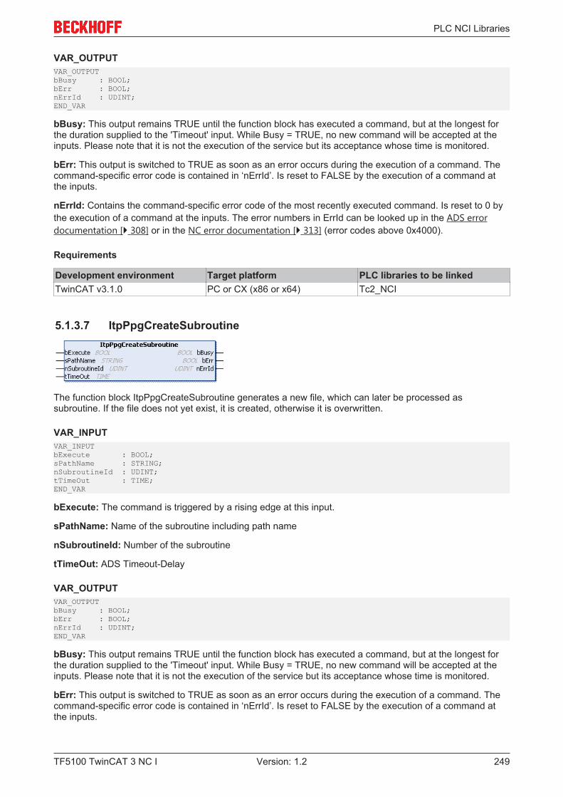
PLC NCI Libraries
TF5100 TwinCAT 3 NC I 249Version: 1.2
VAR_OUTPUTVAR_OUTPUTbBusy : BOOL;bErr : BOOL;nErrId : UDINT;END_VAR
bBusy: This output remains TRUE until the function block has executed a command, but at the longest forthe duration supplied to the 'Timeout' input. While Busy = TRUE, no new command will be accepted at theinputs. Please note that it is not the execution of the service but its acceptance whose time is monitored.
bErr: This output is switched to TRUE as soon as an error occurs during the execution of a command. Thecommand-specific error code is contained in ‘nErrId’. Is reset to FALSE by the execution of a command atthe inputs.
nErrId: Contains the command-specific error code of the most recently executed command. Is reset to 0 bythe execution of a command at the inputs. The error numbers in ErrId can be looked up in the ADS errordocumentation [} 308] or in the NC error documentation [} 313] (error codes above 0x4000).
Requirements
Development environment Target platform PLC libraries to be linkedTwinCAT v3.1.0 PC or CX (x86 or x64) Tc2_NCI
5.1.3.7 ItpPpgCreateSubroutine
The function block ItpPpgCreateSubroutine generates a new file, which can later be processed assubroutine. If the file does not yet exist, it is created, otherwise it is overwritten.
VAR_INPUTVAR_INPUTbExecute : BOOL;sPathName : STRING;nSubroutineId : UDINT;tTimeOut : TIME;END_VAR
bExecute: The command is triggered by a rising edge at this input.
sPathName: Name of the subroutine including path name
nSubroutineId: Number of the subroutine
tTimeOut: ADS Timeout-Delay
VAR_OUTPUTVAR_OUTPUTbBusy : BOOL;bErr : BOOL;nErrId : UDINT;END_VAR
bBusy: This output remains TRUE until the function block has executed a command, but at the longest forthe duration supplied to the 'Timeout' input. While Busy = TRUE, no new command will be accepted at theinputs. Please note that it is not the execution of the service but its acceptance whose time is monitored.
bErr: This output is switched to TRUE as soon as an error occurs during the execution of a command. Thecommand-specific error code is contained in ‘nErrId’. Is reset to FALSE by the execution of a command atthe inputs.
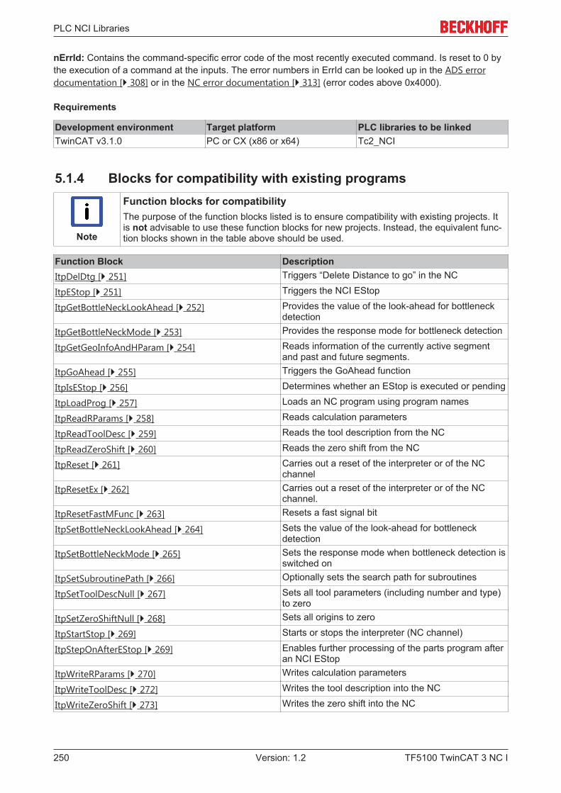
PLC NCI Libraries
TF5100 TwinCAT 3 NC I250 Version: 1.2
nErrId: Contains the command-specific error code of the most recently executed command. Is reset to 0 bythe execution of a command at the inputs. The error numbers in ErrId can be looked up in the ADS errordocumentation [} 308] or in the NC error documentation [} 313] (error codes above 0x4000).
Requirements
Development environment Target platform PLC libraries to be linkedTwinCAT v3.1.0 PC or CX (x86 or x64) Tc2_NCI
5.1.4 Blocks for compatibility with existing programs
Note
Function blocks for compatibilityThe purpose of the function blocks listed is to ensure compatibility with existing projects. Itis not advisable to use these function blocks for new projects. Instead, the equivalent func-tion blocks shown in the table above should be used.
Function Block DescriptionItpDelDtg [} 251] Triggers “Delete Distance to go” in the NC
ItpEStop [} 251] Triggers the NCI EStop
ItpGetBottleNeckLookAhead [} 252] Provides the value of the look-ahead for bottleneckdetection
ItpGetBottleNeckMode [} 253] Provides the response mode for bottleneck detection
ItpGetGeoInfoAndHParam [} 254] Reads information of the currently active segmentand past and future segments.
ItpGoAhead [} 255] Triggers the GoAhead function
ItpIsEStop [} 256] Determines whether an EStop is executed or pending
ItpLoadProg [} 257] Loads an NC program using program names
ItpReadRParams [} 258] Reads calculation parameters
ItpReadToolDesc [} 259] Reads the tool description from the NC
ItpReadZeroShift [} 260] Reads the zero shift from the NC
ItpReset [} 261] Carries out a reset of the interpreter or of the NCchannel
ItpResetEx [} 262] Carries out a reset of the interpreter or of the NCchannel.
ItpResetFastMFunc [} 263] Resets a fast signal bit
ItpSetBottleNeckLookAhead [} 264] Sets the value of the look-ahead for bottleneckdetection
ItpSetBottleNeckMode [} 265] Sets the response mode when bottleneck detection isswitched on
ItpSetSubroutinePath [} 266] Optionally sets the search path for subroutines
ItpSetToolDescNull [} 267] Sets all tool parameters (including number and type)to zero
ItpSetZeroShiftNull [} 268] Sets all origins to zero
ItpStartStop [} 269] Starts or stops the interpreter (NC channel)
ItpStepOnAfterEStop [} 269] Enables further processing of the parts program afteran NCI EStop
ItpWriteRParams [} 270] Writes calculation parameters
ItpWriteToolDesc [} 272] Writes the tool description into the NC
ItpWriteZeroShift [} 273] Writes the zero shift into the NC
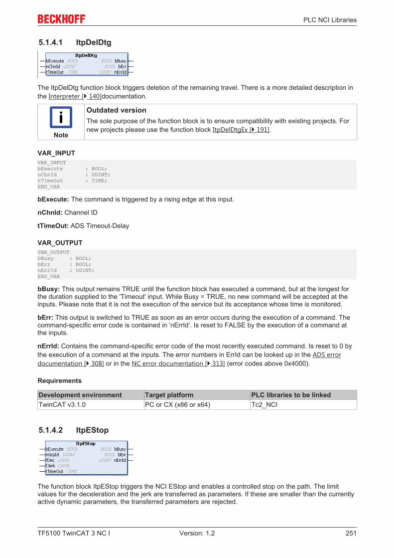
PLC NCI Libraries
TF5100 TwinCAT 3 NC I 251Version: 1.2
5.1.4.1 ItpDelDtg
The ItpDelDtg function block triggers deletion of the remaining travel. There is a more detailed description inthe Interpreter [} 140]documentation.
Note
Outdated versionThe sole purpose of the function block is to ensure compatibility with existing projects. Fornew projects please use the function block ItpDelDtgEx [} 191].
VAR_INPUTVAR_INPUTbExecute : BOOL;nChnId : UDINT;tTimeOut : TIME;END_VAR
bExecute: The command is triggered by a rising edge at this input.
nChnId: Channel ID
tTimeOut: ADS Timeout-Delay
VAR_OUTPUTVAR_OUTPUTbBusy : BOOL;bErr : BOOL;nErrId : UDINT;END_VAR
bBusy: This output remains TRUE until the function block has executed a command, but at the longest forthe duration supplied to the 'Timeout' input. While Busy = TRUE, no new command will be accepted at theinputs. Please note that it is not the execution of the service but its acceptance whose time is monitored.
bErr: This output is switched to TRUE as soon as an error occurs during the execution of a command. Thecommand-specific error code is contained in ‘nErrId’. Is reset to FALSE by the execution of a command atthe inputs.
nErrId: Contains the command-specific error code of the most recently executed command. Is reset to 0 bythe execution of a command at the inputs. The error numbers in ErrId can be looked up in the ADS errordocumentation [} 308] or in the NC error documentation [} 313] (error codes above 0x4000).
Requirements
Development environment Target platform PLC libraries to be linkedTwinCAT v3.1.0 PC or CX (x86 or x64) Tc2_NCI
5.1.4.2 ItpEStop
The function block ItpEStop triggers the NCI EStop and enables a controlled stop on the path. The limitvalues for the deceleration and the jerk are transferred as parameters. If these are smaller than the currentlyactive dynamic parameters, the transferred parameters are rejected.
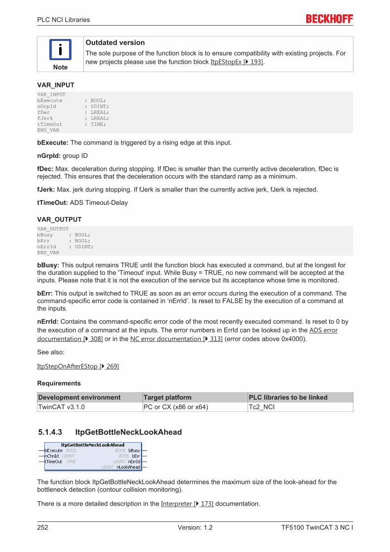
PLC NCI Libraries
TF5100 TwinCAT 3 NC I252 Version: 1.2
Note
Outdated versionThe sole purpose of the function block is to ensure compatibility with existing projects. Fornew projects please use the function block ItpEStopEx [} 193].
VAR_INPUTVAR_INPUTbExecute : BOOL;nGrpId : UDINT;fDec : LREAL;fJerk : LREAL;tTimeOut : TIME;END_VAR
bExecute: The command is triggered by a rising edge at this input.
nGrpId: group ID
fDec: Max. deceleration during stopping. If fDec is smaller than the currently active deceleration, fDec isrejected. This ensures that the deceleration occurs with the standard ramp as a minimum.
fJerk: Max. jerk during stopping. If fJerk is smaller than the currently active jerk, fJerk is rejected.
tTimeOut: ADS Timeout-Delay
VAR_OUTPUTVAR_OUTPUTbBusy : BOOL;bErr : BOOL;nErrId : UDINT;END_VAR
bBusy: This output remains TRUE until the function block has executed a command, but at the longest forthe duration supplied to the 'Timeout' input. While Busy = TRUE, no new command will be accepted at theinputs. Please note that it is not the execution of the service but its acceptance whose time is monitored.
bErr: This output is switched to TRUE as soon as an error occurs during the execution of a command. Thecommand-specific error code is contained in ‘nErrId’. Is reset to FALSE by the execution of a command atthe inputs.
nErrId: Contains the command-specific error code of the most recently executed command. Is reset to 0 bythe execution of a command at the inputs. The error numbers in ErrId can be looked up in the ADS errordocumentation [} 308] or in the NC error documentation [} 313] (error codes above 0x4000).
See also:
ItpStepOnAfterEStop [} 269]
Requirements
Development environment Target platform PLC libraries to be linkedTwinCAT v3.1.0 PC or CX (x86 or x64) Tc2_NCI
5.1.4.3 ItpGetBottleNeckLookAhead
The function block ItpGetBottleNeckLookAhead determines the maximum size of the look-ahead for thebottleneck detection (contour collision monitoring).
There is a more detailed description in the Interpreter [} 173] documentation.
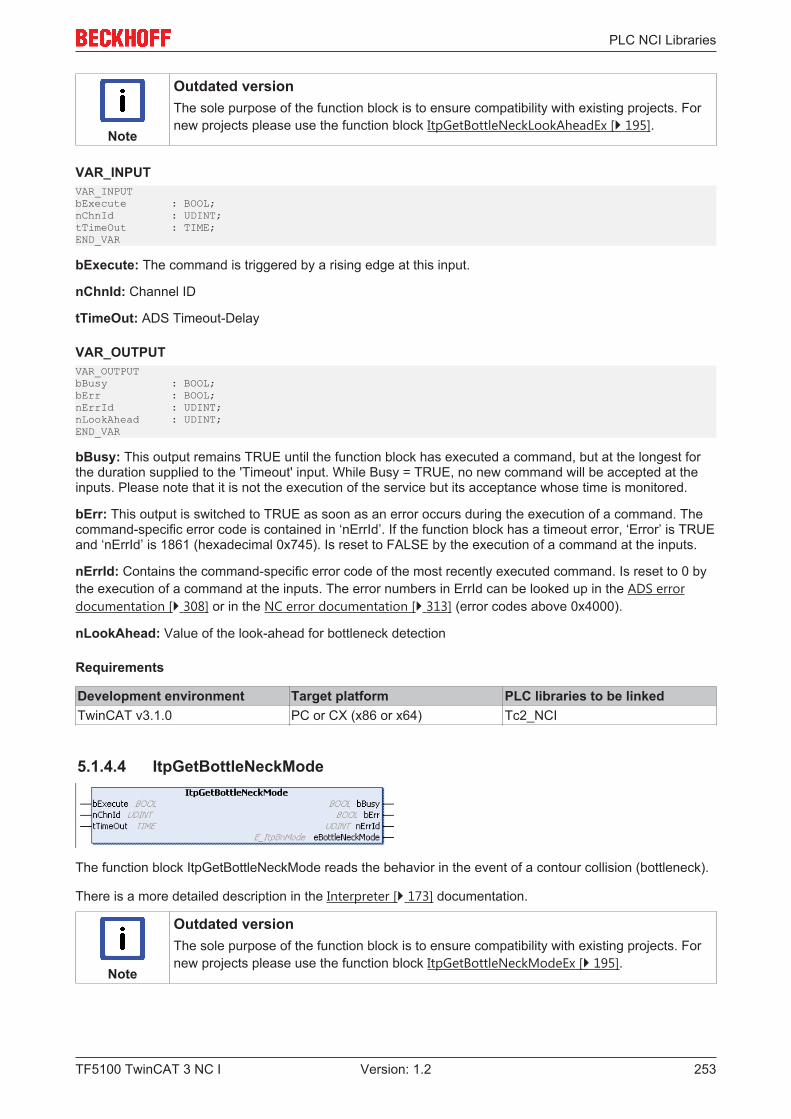
PLC NCI Libraries
TF5100 TwinCAT 3 NC I 253Version: 1.2
Note
Outdated versionThe sole purpose of the function block is to ensure compatibility with existing projects. Fornew projects please use the function block ItpGetBottleNeckLookAheadEx [} 195].
VAR_INPUTVAR_INPUTbExecute : BOOL;nChnId : UDINT;tTimeOut : TIME;END_VAR
bExecute: The command is triggered by a rising edge at this input.
nChnId: Channel ID
tTimeOut: ADS Timeout-Delay
VAR_OUTPUTVAR_OUTPUTbBusy : BOOL;bErr : BOOL;nErrId : UDINT;nLookAhead : UDINT;END_VAR
bBusy: This output remains TRUE until the function block has executed a command, but at the longest forthe duration supplied to the 'Timeout' input. While Busy = TRUE, no new command will be accepted at theinputs. Please note that it is not the execution of the service but its acceptance whose time is monitored.
bErr: This output is switched to TRUE as soon as an error occurs during the execution of a command. Thecommand-specific error code is contained in ‘nErrId’. If the function block has a timeout error, ‘Error’ is TRUEand ‘nErrId’ is 1861 (hexadecimal 0x745). Is reset to FALSE by the execution of a command at the inputs.
nErrId: Contains the command-specific error code of the most recently executed command. Is reset to 0 bythe execution of a command at the inputs. The error numbers in ErrId can be looked up in the ADS errordocumentation [} 308] or in the NC error documentation [} 313] (error codes above 0x4000).
nLookAhead: Value of the look-ahead for bottleneck detection
Requirements
Development environment Target platform PLC libraries to be linkedTwinCAT v3.1.0 PC or CX (x86 or x64) Tc2_NCI
5.1.4.4 ItpGetBottleNeckMode
The function block ItpGetBottleNeckMode reads the behavior in the event of a contour collision (bottleneck).
There is a more detailed description in the Interpreter [} 173] documentation.
Note
Outdated versionThe sole purpose of the function block is to ensure compatibility with existing projects. Fornew projects please use the function block ItpGetBottleNeckModeEx [} 195].
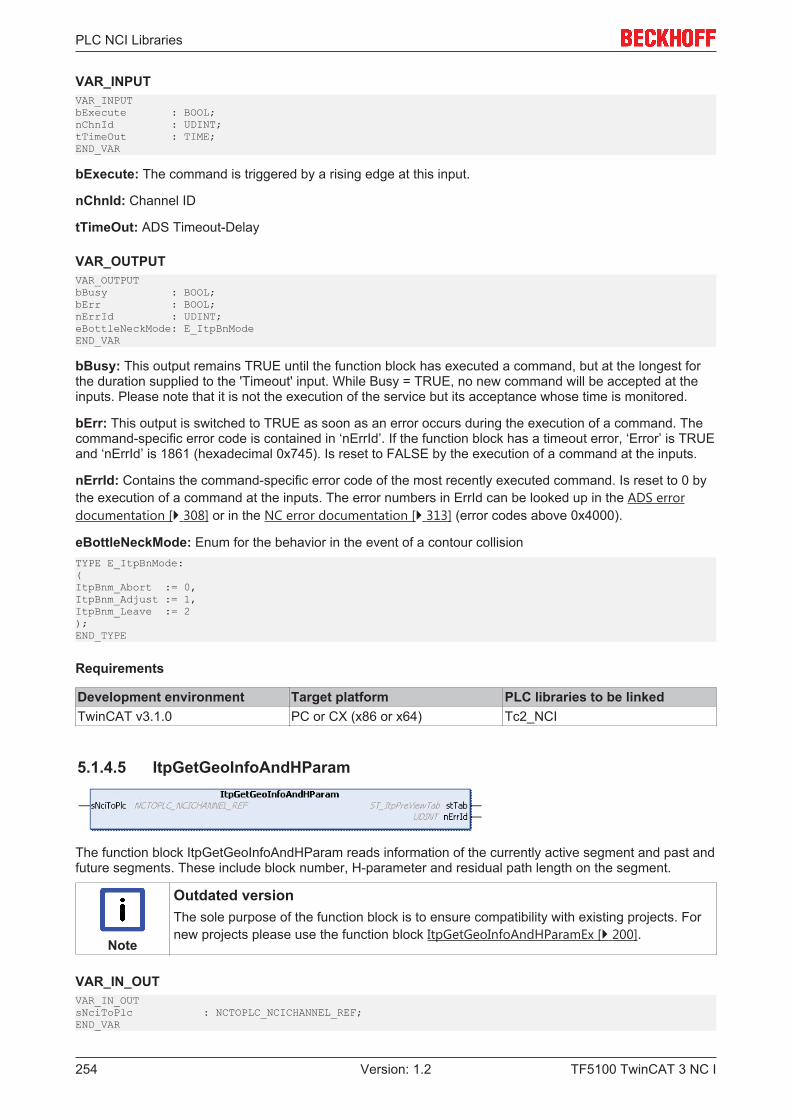
PLC NCI Libraries
TF5100 TwinCAT 3 NC I254 Version: 1.2
VAR_INPUTVAR_INPUTbExecute : BOOL;nChnId : UDINT;tTimeOut : TIME;END_VAR
bExecute: The command is triggered by a rising edge at this input.
nChnId: Channel ID
tTimeOut: ADS Timeout-Delay
VAR_OUTPUTVAR_OUTPUTbBusy : BOOL;bErr : BOOL;nErrId : UDINT;eBottleNeckMode: E_ItpBnModeEND_VAR
bBusy: This output remains TRUE until the function block has executed a command, but at the longest forthe duration supplied to the 'Timeout' input. While Busy = TRUE, no new command will be accepted at theinputs. Please note that it is not the execution of the service but its acceptance whose time is monitored.
bErr: This output is switched to TRUE as soon as an error occurs during the execution of a command. Thecommand-specific error code is contained in ‘nErrId’. If the function block has a timeout error, ‘Error’ is TRUEand ‘nErrId’ is 1861 (hexadecimal 0x745). Is reset to FALSE by the execution of a command at the inputs.
nErrId: Contains the command-specific error code of the most recently executed command. Is reset to 0 bythe execution of a command at the inputs. The error numbers in ErrId can be looked up in the ADS errordocumentation [} 308] or in the NC error documentation [} 313] (error codes above 0x4000).
eBottleNeckMode: Enum for the behavior in the event of a contour collisionTYPE E_ItpBnMode:(ItpBnm_Abort := 0,ItpBnm_Adjust := 1,ItpBnm_Leave := 2);END_TYPE
Requirements
Development environment Target platform PLC libraries to be linkedTwinCAT v3.1.0 PC or CX (x86 or x64) Tc2_NCI
5.1.4.5 ItpGetGeoInfoAndHParam
The function block ItpGetGeoInfoAndHParam reads information of the currently active segment and past andfuture segments. These include block number, H-parameter and residual path length on the segment.
Note
Outdated versionThe sole purpose of the function block is to ensure compatibility with existing projects. Fornew projects please use the function block ItpGetGeoInfoAndHParamEx [} 200].
VAR_IN_OUTVAR_IN_OUTsNciToPlc : NCTOPLC_NCICHANNEL_REF;END_VAR
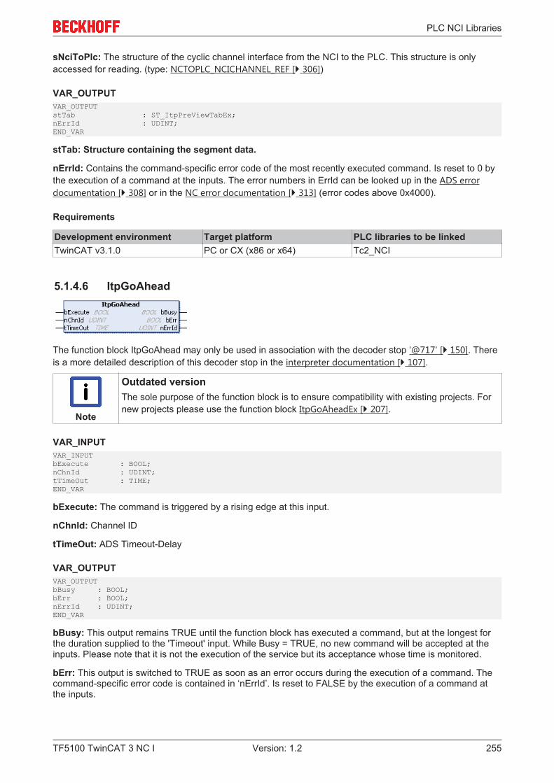
PLC NCI Libraries
TF5100 TwinCAT 3 NC I 255Version: 1.2
sNciToPlc: The structure of the cyclic channel interface from the NCI to the PLC. This structure is onlyaccessed for reading. (type: NCTOPLC_NCICHANNEL_REF [} 306])
VAR_OUTPUTVAR_OUTPUTstTab : ST_ItpPreViewTabEx;nErrId : UDINT;END_VAR
stTab: Structure containing the segment data.
nErrId: Contains the command-specific error code of the most recently executed command. Is reset to 0 bythe execution of a command at the inputs. The error numbers in ErrId can be looked up in the ADS errordocumentation [} 308] or in the NC error documentation [} 313] (error codes above 0x4000).
Requirements
Development environment Target platform PLC libraries to be linkedTwinCAT v3.1.0 PC or CX (x86 or x64) Tc2_NCI
5.1.4.6 ItpGoAhead
The function block ItpGoAhead may only be used in association with the decoder stop '@717' [} 150]. Thereis a more detailed description of this decoder stop in the interpreter documentation [} 107].
Note
Outdated versionThe sole purpose of the function block is to ensure compatibility with existing projects. Fornew projects please use the function block ItpGoAheadEx [} 207].
VAR_INPUTVAR_INPUTbExecute : BOOL;nChnId : UDINT;tTimeOut : TIME;END_VAR
bExecute: The command is triggered by a rising edge at this input.
nChnId: Channel ID
tTimeOut: ADS Timeout-Delay
VAR_OUTPUTVAR_OUTPUTbBusy : BOOL;bErr : BOOL;nErrId : UDINT;END_VAR
bBusy: This output remains TRUE until the function block has executed a command, but at the longest forthe duration supplied to the 'Timeout' input. While Busy = TRUE, no new command will be accepted at theinputs. Please note that it is not the execution of the service but its acceptance whose time is monitored.
bErr: This output is switched to TRUE as soon as an error occurs during the execution of a command. Thecommand-specific error code is contained in ‘nErrId’. Is reset to FALSE by the execution of a command atthe inputs.
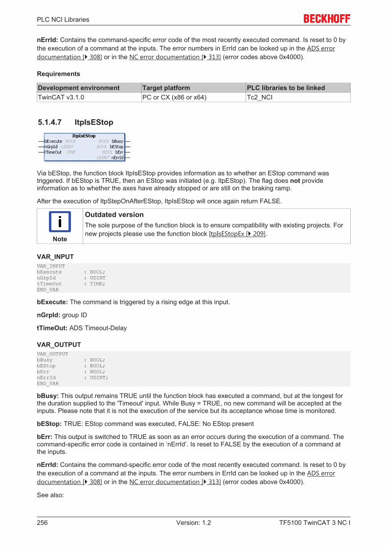
PLC NCI Libraries
TF5100 TwinCAT 3 NC I256 Version: 1.2
nErrId: Contains the command-specific error code of the most recently executed command. Is reset to 0 bythe execution of a command at the inputs. The error numbers in ErrId can be looked up in the ADS errordocumentation [} 308] or in the NC error documentation [} 313] (error codes above 0x4000).
Requirements
Development environment Target platform PLC libraries to be linkedTwinCAT v3.1.0 PC or CX (x86 or x64) Tc2_NCI
5.1.4.7 ItpIsEStop
Via bEStop, the function block ItpIsEStop provides information as to whether an EStop command wastriggered. If bEStop is TRUE, then an EStop was initiated (e.g. ItpEStop). The flag does not provideinformation as to whether the axes have already stopped or are still on the braking ramp.
After the execution of ItpStepOnAfterEStop, ItpIsEStop will once again return FALSE.
Note
Outdated versionThe sole purpose of the function block is to ensure compatibility with existing projects. Fornew projects please use the function block ItpIsEStopEx [} 209].
VAR_INPUTVAR_INPUTbExecute : BOOL;nGrpId : UDINTtTimeOut : TIME;END_VAR
bExecute: The command is triggered by a rising edge at this input.
nGrpId: group ID
tTimeOut: ADS Timeout-Delay
VAR_OUTPUTVAR_OUTPUTbBusy : BOOL;bEStop : BOOL;bErr : BOOL;nErrId : UDINT;END_VAR
bBusy: This output remains TRUE until the function block has executed a command, but at the longest forthe duration supplied to the 'Timeout' input. While Busy = TRUE, no new command will be accepted at theinputs. Please note that it is not the execution of the service but its acceptance whose time is monitored.
bEStop: TRUE: EStop command was executed, FALSE: No EStop present
bErr: This output is switched to TRUE as soon as an error occurs during the execution of a command. Thecommand-specific error code is contained in ‘nErrId’. Is reset to FALSE by the execution of a command atthe inputs.
nErrId: Contains the command-specific error code of the most recently executed command. Is reset to 0 bythe execution of a command at the inputs. The error numbers in ErrId can be looked up in the ADS errordocumentation [} 308] or in the NC error documentation [} 313] (error codes above 0x4000).
See also:
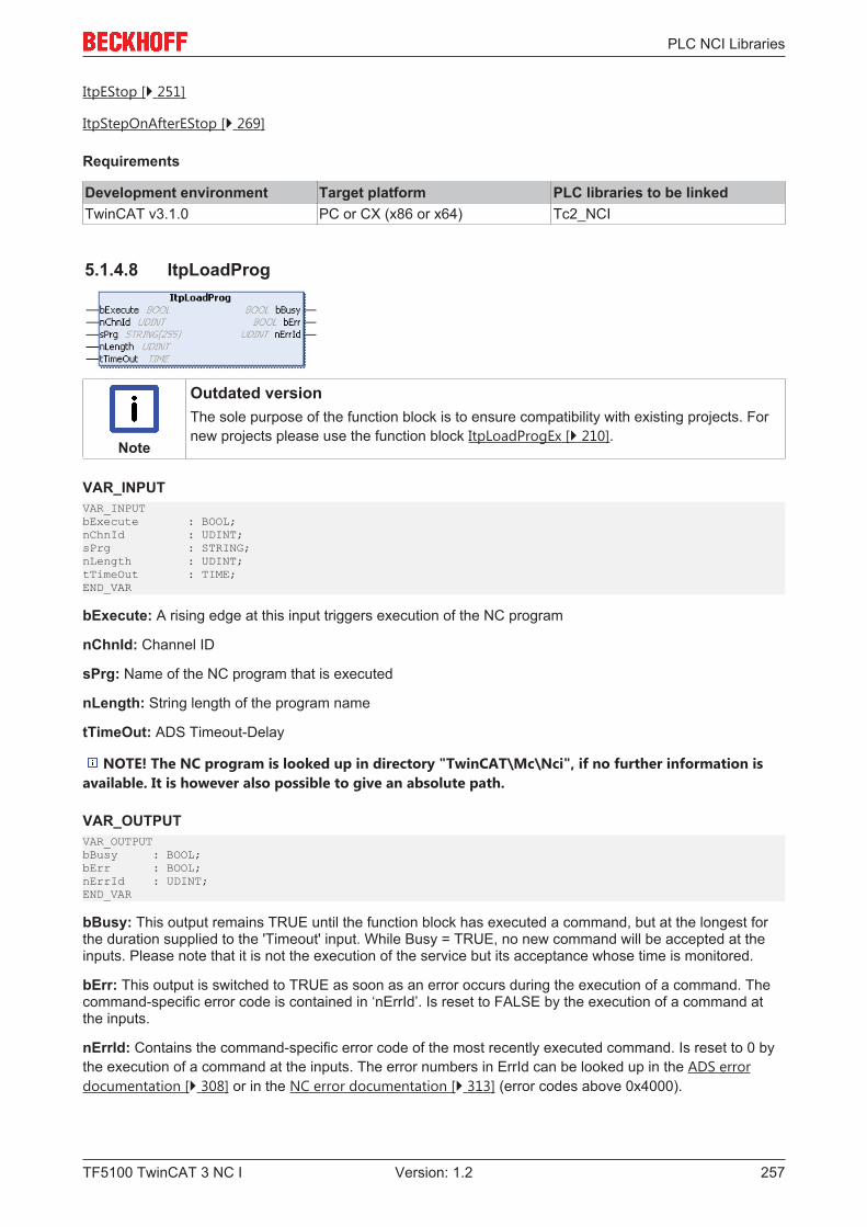
PLC NCI Libraries
TF5100 TwinCAT 3 NC I 257Version: 1.2
ItpEStop [} 251]
ItpStepOnAfterEStop [} 269]
Requirements
Development environment Target platform PLC libraries to be linkedTwinCAT v3.1.0 PC or CX (x86 or x64) Tc2_NCI
5.1.4.8 ItpLoadProg
Note
Outdated versionThe sole purpose of the function block is to ensure compatibility with existing projects. Fornew projects please use the function block ItpLoadProgEx [} 210].
VAR_INPUTVAR_INPUTbExecute : BOOL;nChnId : UDINT;sPrg : STRING;nLength : UDINT;tTimeOut : TIME;END_VAR
bExecute: A rising edge at this input triggers execution of the NC program
nChnId: Channel ID
sPrg: Name of the NC program that is executed
nLength: String length of the program name
tTimeOut: ADS Timeout-Delay
NOTE! The NC program is looked up in directory "TwinCAT\Mc\Nci", if no further information isavailable. It is however also possible to give an absolute path.
VAR_OUTPUTVAR_OUTPUTbBusy : BOOL;bErr : BOOL;nErrId : UDINT;END_VAR
bBusy: This output remains TRUE until the function block has executed a command, but at the longest forthe duration supplied to the 'Timeout' input. While Busy = TRUE, no new command will be accepted at theinputs. Please note that it is not the execution of the service but its acceptance whose time is monitored.
bErr: This output is switched to TRUE as soon as an error occurs during the execution of a command. Thecommand-specific error code is contained in ‘nErrId’. Is reset to FALSE by the execution of a command atthe inputs.
nErrId: Contains the command-specific error code of the most recently executed command. Is reset to 0 bythe execution of a command at the inputs. The error numbers in ErrId can be looked up in the ADS errordocumentation [} 308] or in the NC error documentation [} 313] (error codes above 0x4000).
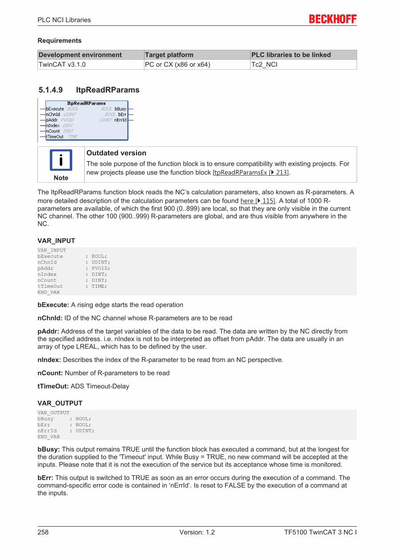
PLC NCI Libraries
TF5100 TwinCAT 3 NC I258 Version: 1.2
Requirements
Development environment Target platform PLC libraries to be linkedTwinCAT v3.1.0 PC or CX (x86 or x64) Tc2_NCI
5.1.4.9 ItpReadRParams
Note
Outdated versionThe sole purpose of the function block is to ensure compatibility with existing projects. Fornew projects please use the function block ItpReadRParamsEx [} 213].
The ItpReadRParams function block reads the NC’s calculation parameters, also known as R-parameters. Amore detailed description of the calculation parameters can be found here [} 115]. A total of 1000 R-parameters are available, of which the first 900 (0..899) are local, so that they are only visible in the currentNC channel. The other 100 (900..999) R-parameters are global, and are thus visible from anywhere in theNC.
VAR_INPUTVAR_INPUTbExecute : BOOL;nChnId : UDINT;pAddr : PVOID;nIndex : DINT;nCount : DINT;tTimeOut : TIME;END_VAR
bExecute: A rising edge starts the read operation
nChnId: ID of the NC channel whose R-parameters are to be read
pAddr: Address of the target variables of the data to be read. The data are written by the NC directly fromthe specified address. i.e. nIndex is not to be interpreted as offset from pAddr. The data are usually in anarray of type LREAL, which has to be defined by the user.
nIndex: Describes the index of the R-parameter to be read from an NC perspective.
nCount: Number of R-parameters to be read
tTimeOut: ADS Timeout-Delay
VAR_OUTPUTVAR_OUTPUTbBusy : BOOL;bErr : BOOL;nErrId : UDINT;END_VAR
bBusy: This output remains TRUE until the function block has executed a command, but at the longest forthe duration supplied to the 'Timeout' input. While Busy = TRUE, no new command will be accepted at theinputs. Please note that it is not the execution of the service but its acceptance whose time is monitored.
bErr: This output is switched to TRUE as soon as an error occurs during the execution of a command. Thecommand-specific error code is contained in ‘nErrId’. Is reset to FALSE by the execution of a command atthe inputs.
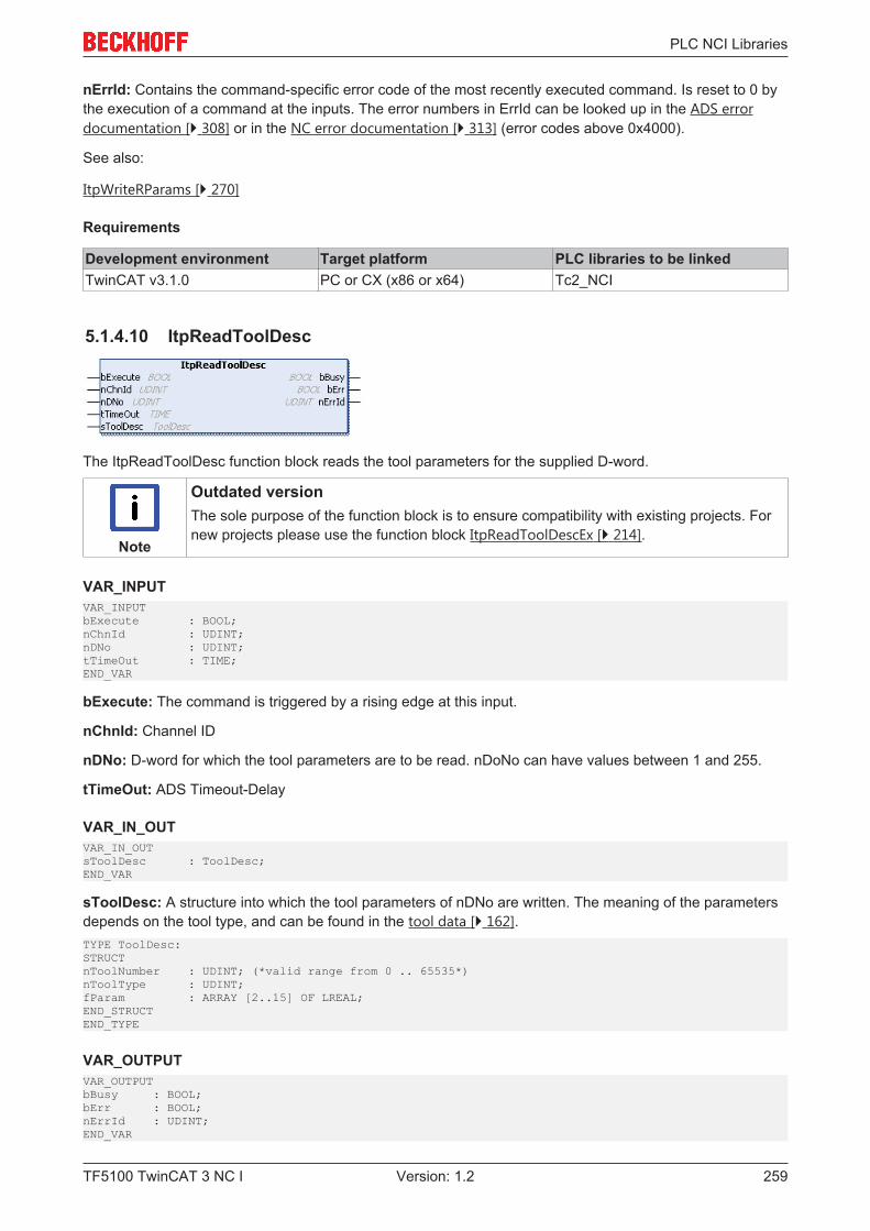
PLC NCI Libraries
TF5100 TwinCAT 3 NC I 259Version: 1.2
nErrId: Contains the command-specific error code of the most recently executed command. Is reset to 0 bythe execution of a command at the inputs. The error numbers in ErrId can be looked up in the ADS errordocumentation [} 308] or in the NC error documentation [} 313] (error codes above 0x4000).
See also:
ItpWriteRParams [} 270]
Requirements
Development environment Target platform PLC libraries to be linkedTwinCAT v3.1.0 PC or CX (x86 or x64) Tc2_NCI
5.1.4.10 ItpReadToolDesc
The ItpReadToolDesc function block reads the tool parameters for the supplied D-word.
Note
Outdated versionThe sole purpose of the function block is to ensure compatibility with existing projects. Fornew projects please use the function block ItpReadToolDescEx [} 214].
VAR_INPUTVAR_INPUTbExecute : BOOL;nChnId : UDINT;nDNo : UDINT;tTimeOut : TIME;END_VAR
bExecute: The command is triggered by a rising edge at this input.
nChnId: Channel ID
nDNo: D-word for which the tool parameters are to be read. nDoNo can have values between 1 and 255.
tTimeOut: ADS Timeout-Delay
VAR_IN_OUTVAR_IN_OUTsToolDesc : ToolDesc;END_VAR
sToolDesc: A structure into which the tool parameters of nDNo are written. The meaning of the parametersdepends on the tool type, and can be found in the tool data [} 162].TYPE ToolDesc:STRUCTnToolNumber : UDINT; (*valid range from 0 .. 65535*)nToolType : UDINT;fParam : ARRAY [2..15] OF LREAL;END_STRUCTEND_TYPE
VAR_OUTPUTVAR_OUTPUTbBusy : BOOL;bErr : BOOL;nErrId : UDINT;END_VAR

PLC NCI Libraries
TF5100 TwinCAT 3 NC I260 Version: 1.2
bBusy: This output remains TRUE until the function block has executed a command, but at the longest forthe duration supplied to the 'Timeout' input. While Busy = TRUE, no new command will be accepted at theinputs. Please note that it is not the execution of the service but its acceptance whose time is monitored.
bErr: This output is switched to TRUE as soon as an error occurs during the execution of a command. Thecommand-specific error code is contained in ‘nErrId’. Is reset to FALSE by the execution of a command atthe inputs.
nErrId: Contains the command-specific error code of the most recently executed command. Is reset to 0 bythe execution of a command at the inputs. The error numbers in ErrId can be looked up in the ADS errordocumentation [} 308] or in the NC error documentation [} 313] (error codes above 0x4000).
see also:
ItpWriteToolDesc [} 272]; ItpSetToolDescNull [} 267]
Requirements
Development environment Target platform PLC libraries to be linkedTwinCAT v3.1.0 PC or CX (x86 or x64) Tc2_NCI
5.1.4.11 ItpReadZeroShift
The ItpReadZeroShift function block reads the offset shift components X, Y and Z for the given zero shift.
NOTE! For reasons of compatibility, there are two entries (coarse and fine) for each axis in eachzero shift (e.g. G54). These two entries must be added together. This function block evaluates boththe entries and adds them together automatically.
Note
Outdated versionThe sole purpose of the function block is to ensure compatibility with existing projects. Fornew projects please use the function block ItpReadZeroShiftEx [} 215].
VAR_INPUTVAR_INPUTbExecute : BOOL;nChnId : UDINT;nZsNo : UDINT;tTimeOut : TIME;END_VAR
bExecute: The command is triggered by a rising edge at this input.
nChnId: Channel ID
nZsNo: Number of the zero shift; on the NC side G54 to G59 are zero shifts. The valid range of values for'nZsNo' is therefore from 54 to 59.
tTimeOut: ADS Timeout-Delay
VAR_IN_OUTVAR_IN_OUTsZeroShiftDesc : ZeroShiftDesc;END_VAR
sZeroShiftDesc: The structure containing the components of the zero shift.
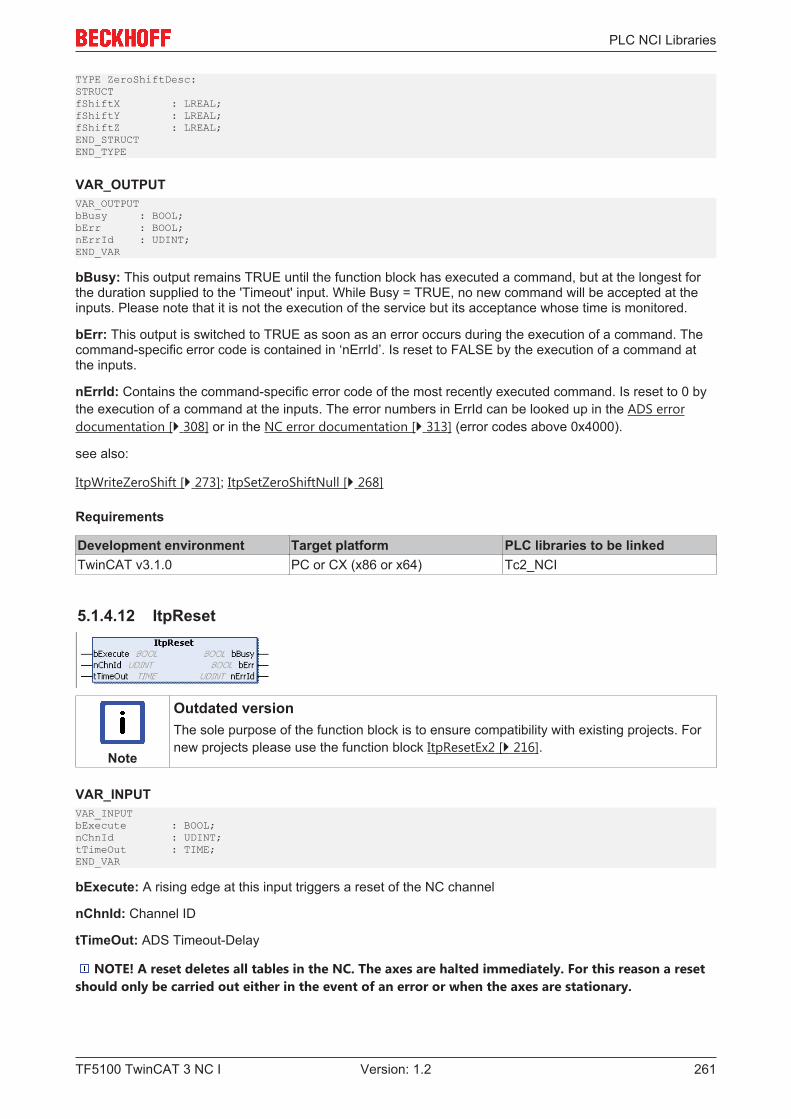
PLC NCI Libraries
TF5100 TwinCAT 3 NC I 261Version: 1.2
TYPE ZeroShiftDesc:STRUCTfShiftX : LREAL;fShiftY : LREAL;fShiftZ : LREAL;END_STRUCTEND_TYPE
VAR_OUTPUTVAR_OUTPUTbBusy : BOOL;bErr : BOOL;nErrId : UDINT;END_VAR
bBusy: This output remains TRUE until the function block has executed a command, but at the longest forthe duration supplied to the 'Timeout' input. While Busy = TRUE, no new command will be accepted at theinputs. Please note that it is not the execution of the service but its acceptance whose time is monitored.
bErr: This output is switched to TRUE as soon as an error occurs during the execution of a command. Thecommand-specific error code is contained in ‘nErrId’. Is reset to FALSE by the execution of a command atthe inputs.
nErrId: Contains the command-specific error code of the most recently executed command. Is reset to 0 bythe execution of a command at the inputs. The error numbers in ErrId can be looked up in the ADS errordocumentation [} 308] or in the NC error documentation [} 313] (error codes above 0x4000).
see also:
ItpWriteZeroShift [} 273]; ItpSetZeroShiftNull [} 268]
Requirements
Development environment Target platform PLC libraries to be linkedTwinCAT v3.1.0 PC or CX (x86 or x64) Tc2_NCI
5.1.4.12 ItpReset
Note
Outdated versionThe sole purpose of the function block is to ensure compatibility with existing projects. Fornew projects please use the function block ItpResetEx2 [} 216].
VAR_INPUTVAR_INPUTbExecute : BOOL;nChnId : UDINT;tTimeOut : TIME;END_VAR
bExecute: A rising edge at this input triggers a reset of the NC channel
nChnId: Channel ID
tTimeOut: ADS Timeout-Delay
NOTE! A reset deletes all tables in the NC. The axes are halted immediately. For this reason a resetshould only be carried out either in the event of an error or when the axes are stationary.

PLC NCI Libraries
TF5100 TwinCAT 3 NC I262 Version: 1.2
VAR_OUTPUTVAR_OUTPUTbBusy : BOOL;bErr : BOOL;nErrId : UDINT;END_VAR
bBusy: This output remains TRUE until the function block has executed a command, but at the longest forthe duration supplied to the 'Timeout' input. While Busy = TRUE, no new command will be accepted at theinputs. Please note that it is not the execution of the service but its acceptance whose time is monitored.
bErr: This output is switched to TRUE as soon as an error occurs during the execution of a command. Thecommand-specific error code is contained in ‘nErrId’. Is reset to FALSE by the execution of a command atthe inputs.
nErrId: Contains the command-specific error code of the most recently executed command. Is reset to 0 bythe execution of a command at the inputs. The error numbers in ErrId can be looked up in the ADS errordocumentation [} 308] or in the NC error documentation [} 313] (error codes above 0x4000).
Requirements
Development environment Target platform PLC libraries to be linkedTwinCAT v3.1.0 PC or CX (x86 or x64) Tc2_NCI
5.1.4.13 ItpResetEx
The function block 'ItpResetEx' executes a channel reset, which deletes all existing tables of the NC channel.In contrast to the conventional ItpReset [} 261], an active channel is stopped first, before the reset isexecuted. This simplifies programming in the PLC, since no explicit check is necessary to ascertain whetherthe axes are still in motion.
Note
Outdated versionThe sole purpose of the function block is to ensure compatibility with existing projects. Fornew projects please use the function block ItpResetEx2 [} 216].
VAR_INPUTVAR_INPUTbExecute : BOOL;nGrpId : UDINT;nChnId : UDINT;tTimeOut : TIME;END_VAR
bExecute: The command is triggered by a rising edge at this input.
nGrpId: group ID
nChnId: Channel ID
tTimeOut: ADS timeout delay (the bBusy signal can be active for longer than tTimeOut)
VAR_OUTPUTVAR_OUTPUTbBusy : BOOL;bErr : BOOL;nErrId : UDINT;END_VAR
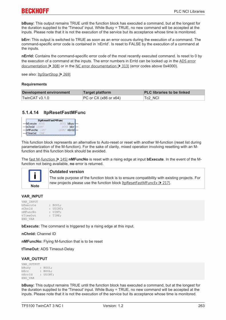
PLC NCI Libraries
TF5100 TwinCAT 3 NC I 263Version: 1.2
bBusy: This output remains TRUE until the function block has executed a command, but at the longest forthe duration supplied to the 'Timeout' input. While Busy = TRUE, no new command will be accepted at theinputs. Please note that it is not the execution of the service but its acceptance whose time is monitored.
bErr: This output is switched to TRUE as soon as an error occurs during the execution of a command. Thecommand-specific error code is contained in ‘nErrId’. Is reset to FALSE by the execution of a command atthe inputs.
nErrId: Contains the command-specific error code of the most recently executed command. Is reset to 0 bythe execution of a command at the inputs. The error numbers in ErrId can be looked up in the ADS errordocumentation [} 308] or in the NC error documentation [} 313] (error codes above 0x4000).
see also: ItpStartStop [} 269]
Requirements
Development environment Target platform PLC libraries to be linkedTwinCAT v3.1.0 PC or CX (x86 or x64) Tc2_NCI
5.1.4.14 ItpResetFastMFunc
This function block represents an alternative to Auto-reset or reset with another M-function (reset list duringparameterization of the M-function). For the sake of clarity, mixed operation involving resetting with an M-function and this function block should be avoided.
The fast M-function [} 145] nMFuncNo is reset with a rising edge at input bExecute. In the event of the M-function not being available, no error is returned.
Note
Outdated versionThe sole purpose of the function block is to ensure compatibility with existing projects. Fornew projects please use the function block ItpResetFastMFuncEx [} 217].
VAR_INPUTVAR_INPUTbExecute : BOOL;nChnId : UDINT;nMFuncNo : UINT;tTimeOut : TIME;END_VAR
bExecute: The command is triggered by a rising edge at this input.
nChnId: Channel ID
nMFuncNo: Flying M-function that is to be reset
tTimeOut: ADS Timeout-Delay
VAR_OUTPUTVAR_OUTPUTbBusy : BOOL;bErr : BOOL;nErrId : UDINT;END_VAR
bBusy: This output remains TRUE until the function block has executed a command, but at the longest forthe duration supplied to the 'Timeout' input. While Busy = TRUE, no new command will be accepted at theinputs. Please note that it is not the execution of the service but its acceptance whose time is monitored.
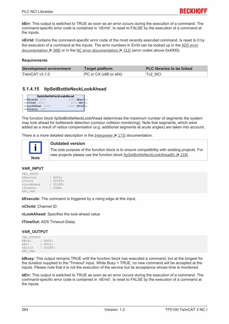
PLC NCI Libraries
TF5100 TwinCAT 3 NC I264 Version: 1.2
bErr: This output is switched to TRUE as soon as an error occurs during the execution of a command. Thecommand-specific error code is contained in ‘nErrId’. Is reset to FALSE by the execution of a command atthe inputs.
nErrId: Contains the command-specific error code of the most recently executed command. Is reset to 0 bythe execution of a command at the inputs. The error numbers in ErrId can be looked up in the ADS errordocumentation [} 308] or in the NC error documentation [} 313] (error codes above 0x4000).
Requirements
Development environment Target platform PLC libraries to be linkedTwinCAT v3.1.0 PC or CX (x86 or x64) Tc2_NCI
5.1.4.15 ItpSetBottleNeckLookAhead
The function block ItpSetBottleNeckLookAhead determines the maximum number of segments the systemmay look ahead for bottleneck detection (contour collision monitoring). Note that segments, which wereadded as a result of radius compensation (e.g. additional segments at acute angles) are taken into account.
There is a more detailed description in the Interpreter [} 173] documentation.
Note
Outdated versionThe sole purpose of the function block is to ensure compatibility with existing projects. Fornew projects please use the function block ItpSetBottleNeckLookAheadEx [} 218].
VAR_INPUTVAR_INPUTbExecute : BOOL;nChnId : UDINT;nLookAhead : UDINT;tTimeOut : TIME;END_VAR
bExecute: The command is triggered by a rising edge at this input.
nChnId: Channel ID
nLookAhead: Specifies the look-ahead value
tTimeOut: ADS Timeout-Delay
VAR_OUTPUTVAR_OUTPUTbBusy : BOOL;bErr : BOOL;nErrId : UDINT;END_VAR
bBusy: This output remains TRUE until the function block has executed a command, but at the longest forthe duration supplied to the 'Timeout' input. While Busy = TRUE, no new command will be accepted at theinputs. Please note that it is not the execution of the service but its acceptance whose time is monitored.
bErr: This output is switched to TRUE as soon as an error occurs during the execution of a command. Thecommand-specific error code is contained in ‘nErrId’. Is reset to FALSE by the execution of a command atthe inputs.

PLC NCI Libraries
TF5100 TwinCAT 3 NC I 265Version: 1.2
nErrId: Contains the command-specific error code of the most recently executed command. Is reset to 0 bythe execution of a command at the inputs. The error numbers in ErrId can be looked up in the ADS errordocumentation [} 308] or in the NC error documentation [} 313] (error codes above 0x4000).
Requirements
Development environment Target platform PLC libraries to be linkedTwinCAT v3.1.0 PC or CX (x86 or x64) Tc2_NCI
5.1.4.16 ItpSetBottleNeckMode
The function block ItpSetBottleNeckMode specifies the behavior in the event of a contour collision(bottleneck).
There is a more detailed description in the Interpreter [} 173] documentation.
Note
Outdated versionThe sole purpose of the function block is to ensure compatibility with existing projects. Fornew projects please use the function block ItpSetBottleNeckModeEx [} 219].
VAR_INPUTVAR_INPUTbExecute : BOOL;nChnId : UDINT;eBottleNeckMode: E_ItpBnModetTimeOut : TIME;END_VAR
bExecute: The command is triggered by a rising edge at this input.
nChnId: Channel ID
eBottleNeckMode: Enum for the behavior in the event of a contour collision
tTimeOut: ADS Timeout-DelayTYPE E_ItpBnMode:(ItpBnm_Abort := 0,ItpBnm_Adjust := 1,ItpBnm_Leave := 2);END_TYPE
VAR_OUTPUTVAR_OUTPUTbBusy : BOOL;bErr : BOOL;nErrId : UDINT;END_VAR
bBusy: This output remains TRUE until the function block has executed a command, but at the longest forthe duration supplied to the 'Timeout' input. While Busy = TRUE, no new command will be accepted at theinputs. Please note that it is not the execution of the service but its acceptance whose time is monitored.
bErr: This output is switched to TRUE as soon as an error occurs during the execution of a command. Thecommand-specific error code is contained in ‘nErrId’. Is reset to FALSE by the execution of a command atthe inputs.
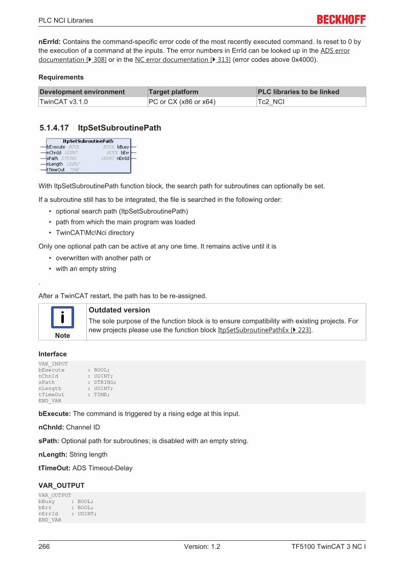
PLC NCI Libraries
TF5100 TwinCAT 3 NC I266 Version: 1.2
nErrId: Contains the command-specific error code of the most recently executed command. Is reset to 0 bythe execution of a command at the inputs. The error numbers in ErrId can be looked up in the ADS errordocumentation [} 308] or in the NC error documentation [} 313] (error codes above 0x4000).
Requirements
Development environment Target platform PLC libraries to be linkedTwinCAT v3.1.0 PC or CX (x86 or x64) Tc2_NCI
5.1.4.17 ItpSetSubroutinePath
With ItpSetSubroutinePath function block, the search path for subroutines can optionally be set.
If a subroutine still has to be integrated, the file is searched in the following order:
• optional search path (ItpSetSubroutinePath)• path from which the main program was loaded• TwinCAT\Mc\Nci directory
Only one optional path can be active at any one time. It remains active until it is
• overwritten with another path or• with an empty string
.
After a TwinCAT restart, the path has to be re-assigned.
Note
Outdated versionThe sole purpose of the function block is to ensure compatibility with existing projects. Fornew projects please use the function block ItpSetSubroutinePathEx [} 223].
InterfaceVAR_INPUTbExecute : BOOL;nChnId : UDINT;sPath : STRING;nLength : UDINT;tTimeOut : TIME;END_VAR
bExecute: The command is triggered by a rising edge at this input.
nChnId: Channel ID
sPath: Optional path for subroutines; is disabled with an empty string.
nLength: String length
tTimeOut: ADS Timeout-Delay
VAR_OUTPUTVAR_OUTPUTbBusy : BOOL;bErr : BOOL;nErrId : UDINT;END_VAR
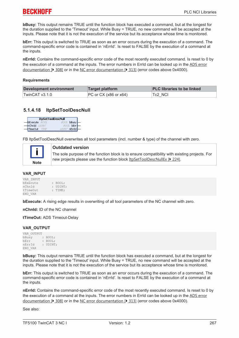
PLC NCI Libraries
TF5100 TwinCAT 3 NC I 267Version: 1.2
bBusy: This output remains TRUE until the function block has executed a command, but at the longest forthe duration supplied to the 'Timeout' input. While Busy = TRUE, no new command will be accepted at theinputs. Please note that it is not the execution of the service but its acceptance whose time is monitored.
bErr: This output is switched to TRUE as soon as an error occurs during the execution of a command. Thecommand-specific error code is contained in ‘nErrId’. Is reset to FALSE by the execution of a command atthe inputs.
nErrId: Contains the command-specific error code of the most recently executed command. Is reset to 0 bythe execution of a command at the inputs. The error numbers in ErrId can be looked up in the ADS errordocumentation [} 308] or in the NC error documentation [} 313] (error codes above 0x4000).
Requirements
Development environment Target platform PLC libraries to be linkedTwinCAT v3.1.0 PC or CX (x86 or x64) Tc2_NCI
5.1.4.18 ItpSetToolDescNull
FB ItpSetToolDescNull overwrites all tool parameters (incl. number & type) of the channel with zero.
Note
Outdated versionThe sole purpose of the function block is to ensure compatibility with existing projects. Fornew projects please use the function block ItpSetToolDescNullEx [} 224].
VAR_INPUTVAR_INPUTbExecute : BOOL;nChnId : UDINT;tTimeOut : TIME;END_VAR
bExecute: A rising edge results in overwriting of all tool parameters of the NC channel with zero.
nChnId: ID of the NC channel
tTimeOut: ADS Timeout-Delay
VAR_OUTPUTVAR_OUTPUTbBusy : BOOL;bErr : BOOL;nErrId : UDINT;END_VAR
bBusy: This output remains TRUE until the function block has executed a command, but at the longest forthe duration supplied to the 'Timeout' input. While Busy = TRUE, no new command will be accepted at theinputs. Please note that it is not the execution of the service but its acceptance whose time is monitored.
bErr: This output is switched to TRUE as soon as an error occurs during the execution of a command. Thecommand-specific error code is contained in ‘nErrId’. Is reset to FALSE by the execution of a command atthe inputs.
nErrId: Contains the command-specific error code of the most recently executed command. Is reset to 0 bythe execution of a command at the inputs. The error numbers in ErrId can be looked up in the ADS errordocumentation [} 308] or in the NC error documentation [} 313] (error codes above 0x4000).
See also:
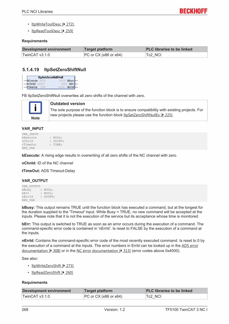
PLC NCI Libraries
TF5100 TwinCAT 3 NC I268 Version: 1.2
• ItpWriteToolDesc [} 272],
• ItpReadToolDesc [} 259]
Requirements
Development environment Target platform PLC libraries to be linkedTwinCAT v3.1.0 PC or CX (x86 or x64) Tc2_NCI
5.1.4.19 ItpSetZeroShiftNull
FB ItpSetZeroShiftNull overwrites all zero shifts of the channel with zero.
Note
Outdated versionThe sole purpose of the function block is to ensure compatibility with existing projects. Fornew projects please use the function block ItpSetZeroShiftNullEx [} 225].
VAR_INPUTVAR_INPUTbExecute : BOOL;nChnId : UDINT;tTimeOut : TIME;END_VAR
bExecute: A rising edge results in overwriting of all zero shifts of the NC channel with zero.
nChnId: ID of the NC channel
tTimeOut: ADS Timeout-Delay
VAR_OUTPUTVAR_OUTPUTbBusy : BOOL;bErr : BOOL;nErrId : UDINT;END_VAR
bBusy: This output remains TRUE until the function block has executed a command, but at the longest forthe duration supplied to the 'Timeout' input. While Busy = TRUE, no new command will be accepted at theinputs. Please note that it is not the execution of the service but its acceptance whose time is monitored.
bErr: This output is switched to TRUE as soon as an error occurs during the execution of a command. Thecommand-specific error code is contained in ‘nErrId’. Is reset to FALSE by the execution of a command atthe inputs.
nErrId: Contains the command-specific error code of the most recently executed command. Is reset to 0 bythe execution of a command at the inputs. The error numbers in ErrId can be looked up in the ADS errordocumentation [} 308] or in the NC error documentation [} 313] (error codes above 0x4000).
See also:
• ItpWriteZeroShift [} 273]
• ItpReadZeroShift [} 260]
Requirements
Development environment Target platform PLC libraries to be linkedTwinCAT v3.1.0 PC or CX (x86 or x64) Tc2_NCI
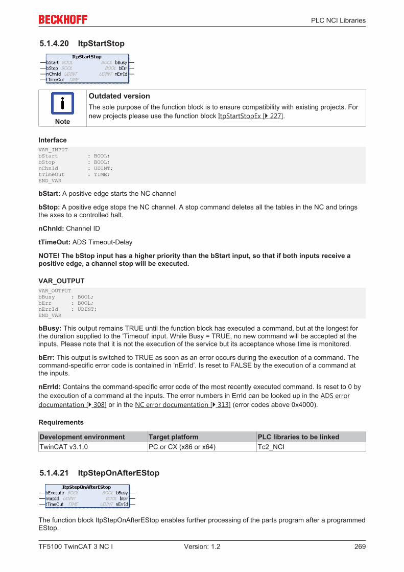
PLC NCI Libraries
TF5100 TwinCAT 3 NC I 269Version: 1.2
5.1.4.20 ItpStartStop
Note
Outdated versionThe sole purpose of the function block is to ensure compatibility with existing projects. Fornew projects please use the function block ItpStartStopEx [} 227].
InterfaceVAR_INPUTbStart : BOOL;bStop : BOOL;nChnId : UDINT;tTimeOut : TIME;END_VAR
bStart: A positive edge starts the NC channel
bStop: A positive edge stops the NC channel. A stop command deletes all the tables in the NC and bringsthe axes to a controlled halt.
nChnId: Channel ID
tTimeOut: ADS Timeout-Delay
NOTE! The bStop input has a higher priority than the bStart input, so that if both inputs receive apositive edge, a channel stop will be executed.
VAR_OUTPUTVAR_OUTPUTbBusy : BOOL;bErr : BOOL;nErrId : UDINT;END_VAR
bBusy: This output remains TRUE until the function block has executed a command, but at the longest forthe duration supplied to the 'Timeout' input. While Busy = TRUE, no new command will be accepted at theinputs. Please note that it is not the execution of the service but its acceptance whose time is monitored.
bErr: This output is switched to TRUE as soon as an error occurs during the execution of a command. Thecommand-specific error code is contained in ‘nErrId’. Is reset to FALSE by the execution of a command atthe inputs.
nErrId: Contains the command-specific error code of the most recently executed command. Is reset to 0 bythe execution of a command at the inputs. The error numbers in ErrId can be looked up in the ADS errordocumentation [} 308] or in the NC error documentation [} 313] (error codes above 0x4000).
Requirements
Development environment Target platform PLC libraries to be linkedTwinCAT v3.1.0 PC or CX (x86 or x64) Tc2_NCI
5.1.4.21 ItpStepOnAfterEStop
The function block ItpStepOnAfterEStop enables further processing of the parts program after a programmedEStop.
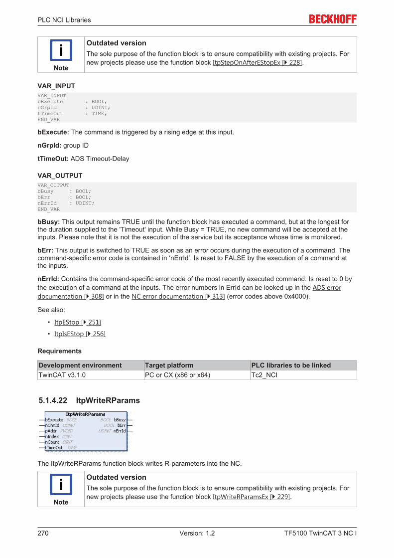
PLC NCI Libraries
TF5100 TwinCAT 3 NC I270 Version: 1.2
Note
Outdated versionThe sole purpose of the function block is to ensure compatibility with existing projects. Fornew projects please use the function block ItpStepOnAfterEStopEx [} 228].
VAR_INPUTVAR_INPUTbExecute : BOOL;nGrpId : UDINT;tTimeOut : TIME;END_VAR
bExecute: The command is triggered by a rising edge at this input.
nGrpId: group ID
tTimeOut: ADS Timeout-Delay
VAR_OUTPUTVAR_OUTPUTbBusy : BOOL;bErr : BOOL;nErrId : UDINT;END_VAR
bBusy: This output remains TRUE until the function block has executed a command, but at the longest forthe duration supplied to the 'Timeout' input. While Busy = TRUE, no new command will be accepted at theinputs. Please note that it is not the execution of the service but its acceptance whose time is monitored.
bErr: This output is switched to TRUE as soon as an error occurs during the execution of a command. Thecommand-specific error code is contained in ‘nErrId’. Is reset to FALSE by the execution of a command atthe inputs.
nErrId: Contains the command-specific error code of the most recently executed command. Is reset to 0 bythe execution of a command at the inputs. The error numbers in ErrId can be looked up in the ADS errordocumentation [} 308] or in the NC error documentation [} 313] (error codes above 0x4000).
See also:
• ItpEStop [} 251]
• ItpIsEStop [} 256]
Requirements
Development environment Target platform PLC libraries to be linkedTwinCAT v3.1.0 PC or CX (x86 or x64) Tc2_NCI
5.1.4.22 ItpWriteRParams
The ItpWriteRParams function block writes R-parameters into the NC.
Note
Outdated versionThe sole purpose of the function block is to ensure compatibility with existing projects. Fornew projects please use the function block ItpWriteRParamsEx [} 229].
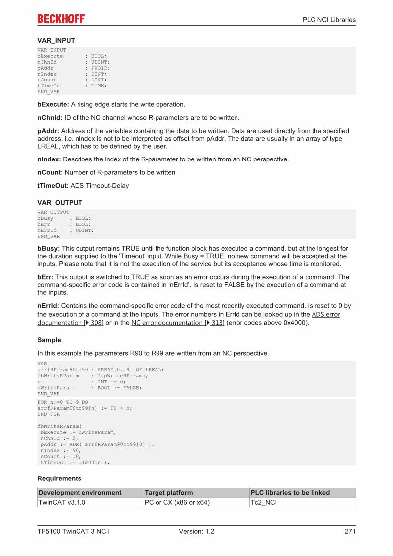
PLC NCI Libraries
TF5100 TwinCAT 3 NC I 271Version: 1.2
VAR_INPUTVAR_INPUTbExecute : BOOL;nChnId : UDINT;pAddr : PVOID;nIndex : DINT;nCount : DINT;tTimeOut : TIME;END_VAR
bExecute: A rising edge starts the write operation.
nChnId: ID of the NC channel whose R-parameters are to be written.
pAddr: Address of the variables containing the data to be written. Data are used directly from the specifiedaddress, i.e. nIndex is not to be interpreted as offset from pAddr. The data are usually in an array of typeLREAL, which has to be defined by the user.
nIndex: Describes the index of the R-parameter to be written from an NC perspective.
nCount: Number of R-parameters to be written
tTimeOut: ADS Timeout-Delay
VAR_OUTPUTVAR_OUTPUTbBusy : BOOL;bErr : BOOL;nErrId : UDINT;END_VAR
bBusy: This output remains TRUE until the function block has executed a command, but at the longest forthe duration supplied to the 'Timeout' input. While Busy = TRUE, no new command will be accepted at theinputs. Please note that it is not the execution of the service but its acceptance whose time is monitored.
bErr: This output is switched to TRUE as soon as an error occurs during the execution of a command. Thecommand-specific error code is contained in ‘nErrId’. Is reset to FALSE by the execution of a command atthe inputs.
nErrId: Contains the command-specific error code of the most recently executed command. Is reset to 0 bythe execution of a command at the inputs. The error numbers in ErrId can be looked up in the ADS errordocumentation [} 308] or in the NC error documentation [} 313] (error codes above 0x4000).
Sample
In this example the parameters R90 to R99 are written from an NC perspective.VARarrfRParam90to99 : ARRAY[0..9] OF LREAL;fbWriteRParam : ItpWriteRParams;n : INT := 0;bWriteParam : BOOL := FALSE;END_VAR
FOR n:=0 TO 9 DOarrfRParam90to99[n] := 90 + n;END_FOR
fbWriteRParam( bExecute := bWriteParam, nChnId := 2, pAddr := ADR( arrfRParam90to99[0] ), nIndex := 90, nCount := 10, tTimeOut := T#200ms );
Requirements
Development environment Target platform PLC libraries to be linkedTwinCAT v3.1.0 PC or CX (x86 or x64) Tc2_NCI
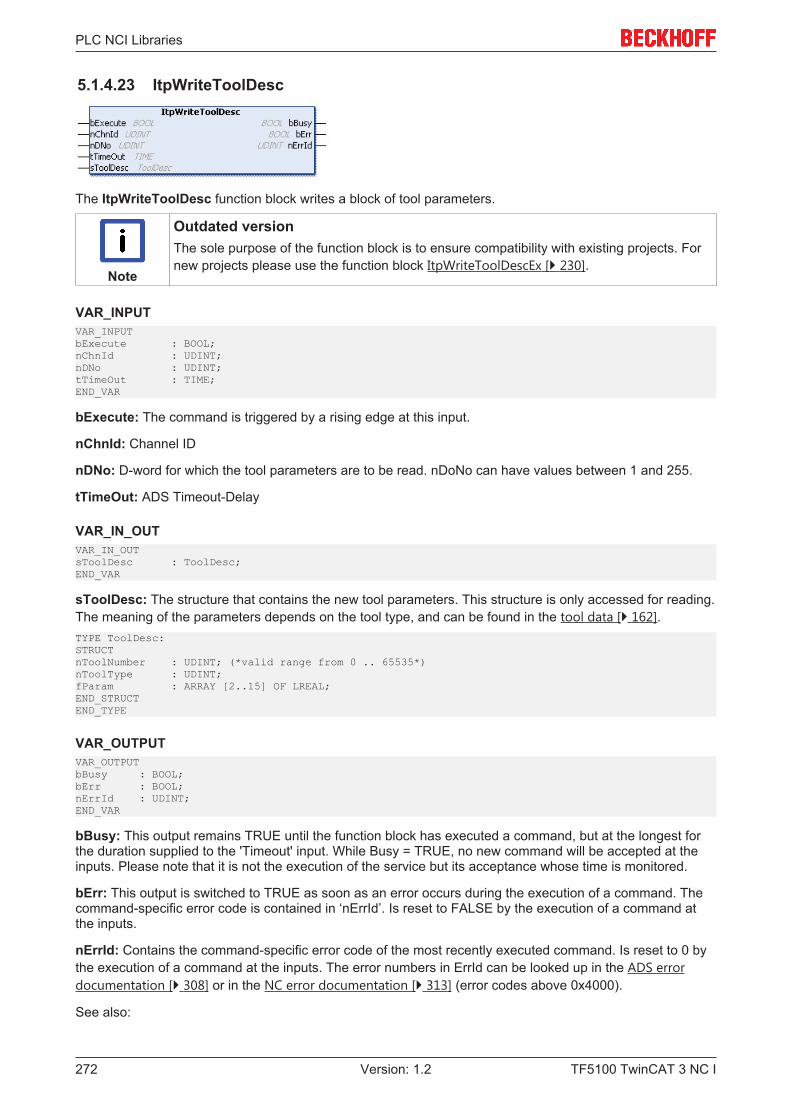
PLC NCI Libraries
TF5100 TwinCAT 3 NC I272 Version: 1.2
5.1.4.23 ItpWriteToolDesc
The ItpWriteToolDesc function block writes a block of tool parameters.
Note
Outdated versionThe sole purpose of the function block is to ensure compatibility with existing projects. Fornew projects please use the function block ItpWriteToolDescEx [} 230].
VAR_INPUTVAR_INPUTbExecute : BOOL;nChnId : UDINT;nDNo : UDINT;tTimeOut : TIME;END_VAR
bExecute: The command is triggered by a rising edge at this input.
nChnId: Channel ID
nDNo: D-word for which the tool parameters are to be read. nDoNo can have values between 1 and 255.
tTimeOut: ADS Timeout-Delay
VAR_IN_OUTVAR_IN_OUTsToolDesc : ToolDesc;END_VAR
sToolDesc: The structure that contains the new tool parameters. This structure is only accessed for reading.The meaning of the parameters depends on the tool type, and can be found in the tool data [} 162].TYPE ToolDesc:STRUCTnToolNumber : UDINT; (*valid range from 0 .. 65535*)nToolType : UDINT;fParam : ARRAY [2..15] OF LREAL;END_STRUCTEND_TYPE
VAR_OUTPUTVAR_OUTPUTbBusy : BOOL;bErr : BOOL;nErrId : UDINT;END_VAR
bBusy: This output remains TRUE until the function block has executed a command, but at the longest forthe duration supplied to the 'Timeout' input. While Busy = TRUE, no new command will be accepted at theinputs. Please note that it is not the execution of the service but its acceptance whose time is monitored.
bErr: This output is switched to TRUE as soon as an error occurs during the execution of a command. Thecommand-specific error code is contained in ‘nErrId’. Is reset to FALSE by the execution of a command atthe inputs.
nErrId: Contains the command-specific error code of the most recently executed command. Is reset to 0 bythe execution of a command at the inputs. The error numbers in ErrId can be looked up in the ADS errordocumentation [} 308] or in the NC error documentation [} 313] (error codes above 0x4000).
See also:

PLC NCI Libraries
TF5100 TwinCAT 3 NC I 273Version: 1.2
• ItpReadToolDesc [} 259]
• ItpSetToolDescNull [} 267]
Requirements
Development environment Target platform PLC libraries to be linkedTwinCAT v3.1.0 PC or CX (x86 or x64) Tc2_NCI
5.1.4.24 ItpWriteZeroShift
The function block ItpWriteZeroShift writes the shift components X, Y and Z for the specified zero shift.
For reasons of compatibility every zero shift that can be set has two parameters (coarse and fine) for eachaxis. When using this function block to write a new zero shift, the new value is written into the 'fineparameter'. A value of 0.0 is entered into the 'coarse parameter'. This makes it possible to use a functionblock such as ItpReadZeroShift [} 260] to read and modify a zero shift and to send it back to the NC.
Note
Outdated versionThe sole purpose of the function block is to ensure compatibility with existing projects. Fornew projects please use the function block ItpWriteZeroShiftEx [} 231].
VAR_INPUTVAR_INPUTbExecute : BOOL;nChnId : UDINT;nZsNo : UDINT;tTimeOut : TIME;END_VAR
bExecute: The command is triggered by a rising edge at this input.
nChnId: Channel ID
nZsNo: Number of the zero shift.
On the NC side G54 to G59 are zero shifts; G58 and G59 can only be edited from the NC program. The validrange of values for 'nZsNo' is therefore from 54 to 57.
tTimeOut: ADS Timeout-Delay
VAR_IN_OUTVAR_IN_OUTsZeroShiftDesc : ZeroShiftDesc;END_VAR
sZeroShiftDesc: The structure containing the components of the zero shift. This structure is only accessedfor reading.TYPE ZeroShiftDesc:STRUCTfShiftX : LREAL;fShiftY : LREAL;fShiftZ : LREAL;END_STRUCTEND_TYPE

PLC NCI Libraries
TF5100 TwinCAT 3 NC I274 Version: 1.2
VAR_OUTPUTVAR_OUTPUTbBusy : BOOL;bErr : BOOL;nErrId : UDINT;END_VAR
bBusy: This output remains TRUE until the function block has executed a command, but at the longest forthe duration supplied to the 'Timeout' input. While Busy = TRUE, no new command will be accepted at theinputs. Please note that it is not the execution of the service but its acceptance whose time is monitored.
bErr: This output is switched to TRUE as soon as an error occurs during the execution of a command. Thecommand-specific error code is contained in ‘nErrId’. Is reset to FALSE by the execution of a command atthe inputs.
nErrId: Contains the command-specific error code of the most recently executed command. Is reset to 0 bythe execution of a command at the inputs. The error numbers in ErrId can be looked up in the ADS errordocumentation [} 308] or in the NC error documentation [} 313] (error codes above 0x4000).
See also:
• ItpReadZeroShift [} 260]
• ItpSetZeroShiftNull [} 273]
Requirements
Development environment Target platform PLC libraries to be linkedTwinCAT v3.1.0 PC or CX (x86 or x64) Tc2_NCI
5.1.5 Obsolete
5.1.5.1 F_GetVersionTcNciUtilities
This function returns part of the three-part version number of the TwinCAT 2 PLC library TcNciUtilities.lib asUINT.
Note
Outdated versionThe sole purpose of this function is to ensure compatibility with existing projects. For newprojects please use the global structure stLibVersion_Tc2_NCI.
VAR_INPUTFUNCTION F_GetVersionNciUtilities
VAR_INPUTnVersionElement : UINT;END_VAR
nVersionElement: Part of the version number to be read (range: [1..3])
Return value
F_GetVersionNciUtilities: Version number
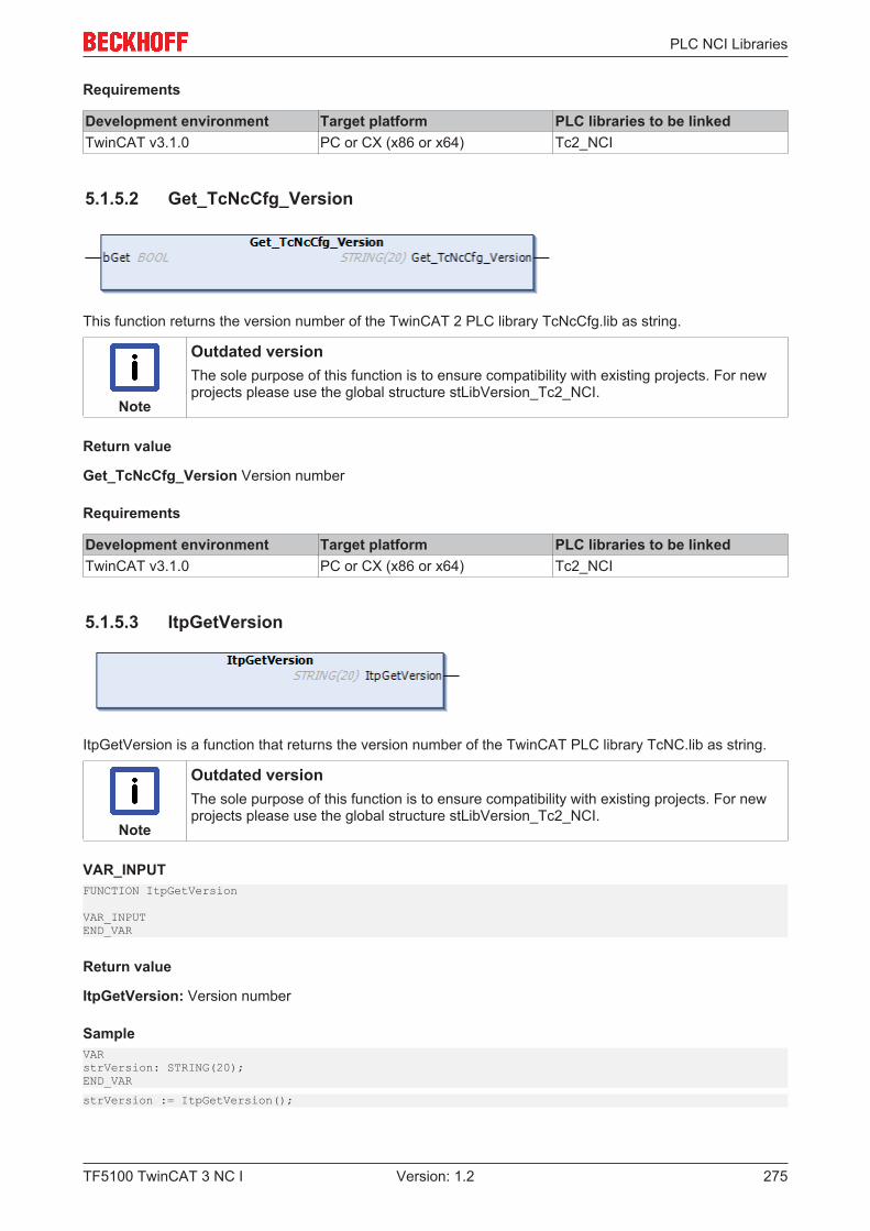
PLC NCI Libraries
TF5100 TwinCAT 3 NC I 275Version: 1.2
Requirements
Development environment Target platform PLC libraries to be linkedTwinCAT v3.1.0 PC or CX (x86 or x64) Tc2_NCI
5.1.5.2 Get_TcNcCfg_Version
This function returns the version number of the TwinCAT 2 PLC library TcNcCfg.lib as string.
Note
Outdated versionThe sole purpose of this function is to ensure compatibility with existing projects. For newprojects please use the global structure stLibVersion_Tc2_NCI.
Return value
Get_TcNcCfg_Version Version number
Requirements
Development environment Target platform PLC libraries to be linkedTwinCAT v3.1.0 PC or CX (x86 or x64) Tc2_NCI
5.1.5.3 ItpGetVersion
ItpGetVersion is a function that returns the version number of the TwinCAT PLC library TcNC.lib as string.
Note
Outdated versionThe sole purpose of this function is to ensure compatibility with existing projects. For newprojects please use the global structure stLibVersion_Tc2_NCI.
VAR_INPUTFUNCTION ItpGetVersion
VAR_INPUTEND_VAR
Return value
ItpGetVersion: Version number
SampleVARstrVersion: STRING(20);END_VAR
strVersion := ItpGetVersion();
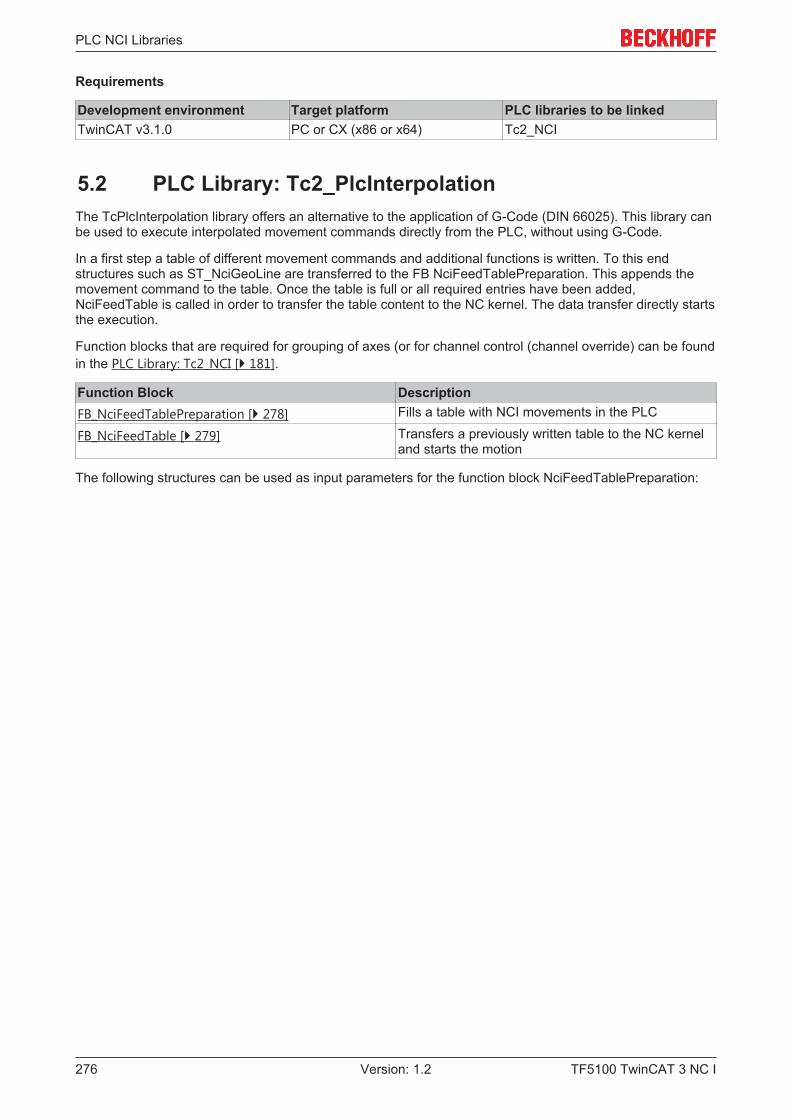
PLC NCI Libraries
TF5100 TwinCAT 3 NC I276 Version: 1.2
Requirements
Development environment Target platform PLC libraries to be linkedTwinCAT v3.1.0 PC or CX (x86 or x64) Tc2_NCI
5.2 PLC Library: Tc2_PlcInterpolationThe TcPlcInterpolation library offers an alternative to the application of G-Code (DIN 66025). This library canbe used to execute interpolated movement commands directly from the PLC, without using G-Code.
In a first step a table of different movement commands and additional functions is written. To this endstructures such as ST_NciGeoLine are transferred to the FB NciFeedTablePreparation. This appends themovement command to the table. Once the table is full or all required entries have been added,NciFeedTable is called in order to transfer the table content to the NC kernel. The data transfer directly startsthe execution.
Function blocks that are required for grouping of axes (or for channel control (channel override) can be foundin the PLC Library: Tc2_NCI [} 181].
Function Block DescriptionFB_NciFeedTablePreparation [} 278] Fills a table with NCI movements in the PLC
FB_NciFeedTable [} 279] Transfers a previously written table to the NC kerneland starts the motion
The following structures can be used as input parameters for the function block NciFeedTablePreparation:
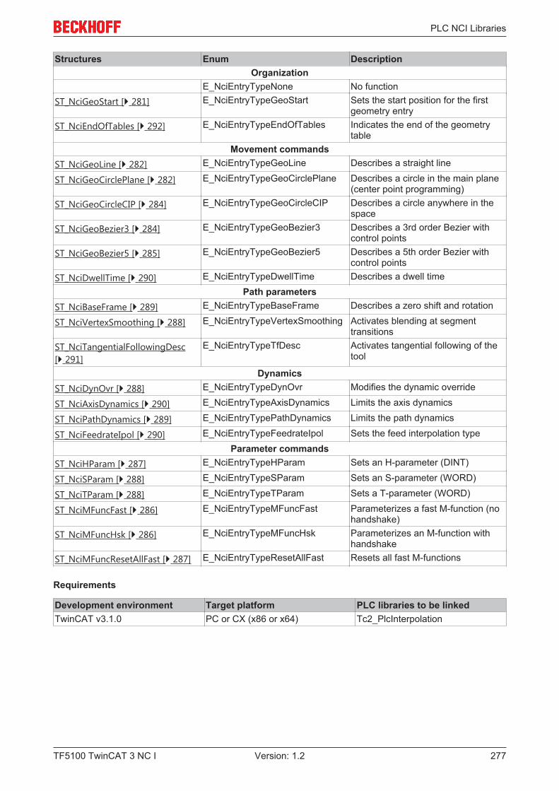
PLC NCI Libraries
TF5100 TwinCAT 3 NC I 277Version: 1.2
Structures Enum DescriptionOrganization
E_NciEntryTypeNone No functionST_NciGeoStart [} 281] E_NciEntryTypeGeoStart Sets the start position for the first
geometry entryST_NciEndOfTables [} 292] E_NciEntryTypeEndOfTables Indicates the end of the geometry
tableMovement commands
ST_NciGeoLine [} 282] E_NciEntryTypeGeoLine Describes a straight line
ST_NciGeoCirclePlane [} 282] E_NciEntryTypeGeoCirclePlane Describes a circle in the main plane(center point programming)
ST_NciGeoCircleCIP [} 284] E_NciEntryTypeGeoCircleCIP Describes a circle anywhere in thespace
ST_NciGeoBezier3 [} 284] E_NciEntryTypeGeoBezier3 Describes a 3rd order Bezier withcontrol points
ST_NciGeoBezier5 [} 285] E_NciEntryTypeGeoBezier5 Describes a 5th order Bezier withcontrol points
ST_NciDwellTime [} 290] E_NciEntryTypeDwellTime Describes a dwell timePath parameters
ST_NciBaseFrame [} 289] E_NciEntryTypeBaseFrame Describes a zero shift and rotation
ST_NciVertexSmoothing [} 288] E_NciEntryTypeVertexSmoothing Activates blending at segmenttransitions
ST_NciTangentialFollowingDesc[} 291]
E_NciEntryTypeTfDesc Activates tangential following of thetool
DynamicsST_NciDynOvr [} 288] E_NciEntryTypeDynOvr Modifies the dynamic override
ST_NciAxisDynamics [} 290] E_NciEntryTypeAxisDynamics Limits the axis dynamics
ST_NciPathDynamics [} 289] E_NciEntryTypePathDynamics Limits the path dynamics
ST_NciFeedrateIpol [} 290] E_NciEntryTypeFeedrateIpol Sets the feed interpolation typeParameter commands
ST_NciHParam [} 287] E_NciEntryTypeHParam Sets an H-parameter (DINT)
ST_NciSParam [} 288] E_NciEntryTypeSParam Sets an S-parameter (WORD)
ST_NciTParam [} 288] E_NciEntryTypeTParam Sets a T-parameter (WORD)
ST_NciMFuncFast [} 286] E_NciEntryTypeMFuncFast Parameterizes a fast M-function (nohandshake)
ST_NciMFuncHsk [} 286] E_NciEntryTypeMFuncHsk Parameterizes an M-function withhandshake
ST_NciMFuncResetAllFast [} 287] E_NciEntryTypeResetAllFast Resets all fast M-functions
Requirements
Development environment Target platform PLC libraries to be linkedTwinCAT v3.1.0 PC or CX (x86 or x64) Tc2_PlcInterpolation
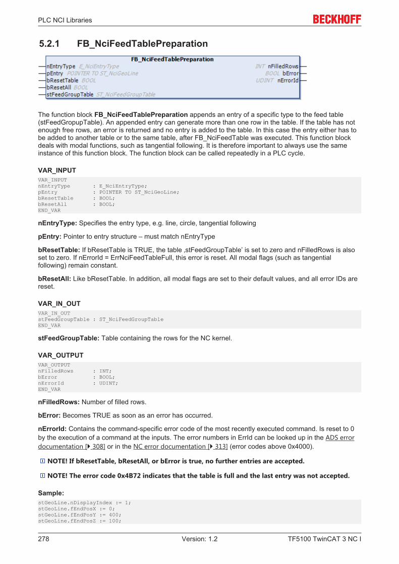
PLC NCI Libraries
TF5100 TwinCAT 3 NC I278 Version: 1.2
5.2.1 FB_NciFeedTablePreparation
The function block FB_NciFeedTablePreparation appends an entry of a specific type to the feed table(stFeedGropupTable). An appended entry can generate more than one row in the table. If the table has notenough free rows, an error is returned and no entry is added to the table. In this case the entry either has tobe added to another table or to the same table, after FB_NciFeedTable was executed. This function blockdeals with modal functions, such as tangential following. It is therefore important to always use the sameinstance of this function block. The function block can be called repeatedly in a PLC cycle.
VAR_INPUTVAR_INPUTnEntryType : E_NciEntryType;pEntry : POINTER TO ST_NciGeoLine;bResetTable : BOOL;bResetAll : BOOL;END_VAR
nEntryType: Specifies the entry type, e.g. line, circle, tangential following
pEntry: Pointer to entry structure – must match nEntryType
bResetTable: If bResetTable is TRUE, the table ‚stFeedGroupTable’ is set to zero and nFilledRows is alsoset to zero. If nErrorId = ErrNciFeedTableFull, this error is reset. All modal flags (such as tangentialfollowing) remain constant.
bResetAll: Like bResetTable. In addition, all modal flags are set to their default values, and all error IDs arereset.
VAR_IN_OUTVAR_IN_OUTstFeedGroupTable : ST_NciFeedGroupTableEND_VAR
stFeedGroupTable: Table containing the rows for the NC kernel.
VAR_OUTPUTVAR_OUTPUTnFilledRows : INT;bError : BOOL;nErrorId : UDINT;END_VAR
nFilledRows: Number of filled rows.
bError: Becomes TRUE as soon as an error has occurred.
nErrorId: Contains the command-specific error code of the most recently executed command. Is reset to 0by the execution of a command at the inputs. The error numbers in ErrId can be looked up in the ADS errordocumentation [} 308] or in the NC error documentation [} 313] (error codes above 0x4000).
NOTE! If bResetTable, bResetAll, or bError is true, no further entries are accepted.
NOTE! The error code 0x4B72 indicates that the table is full and the last entry was not accepted.
Sample:stGeoLine.nDisplayIndex := 1;stGeoLine.fEndPosX := 0;stGeoLine.fEndPosY := 400;stGeoLine.fEndPosZ := 100;
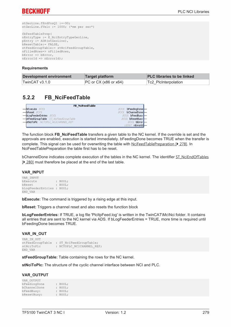
PLC NCI Libraries
TF5100 TwinCAT 3 NC I 279Version: 1.2
stGeoLine.fEndPosQ1 :=-90;stGeoLine.fVelo := 1000; (*mm per sec*)
fbFeedTablePrep(nEntryType := E_NciEntryTypeGeoLine,pEntry := ADR(stGeoLine),bResetTable:= FALSE,stFeedGroupTable:= stNciFeedGroupTable,nFilledRows=> nFilledRows,bError => bError,nErrorId => nErrorId);
Requirements
Development environment Target platform PLC libraries to be linkedTwinCAT v3.1.0 PC or CX (x86 or x64) Tc2_PlcInterpolation
5.2.2 FB_NciFeedTable
The function block FB_NciFeedTable transfers a given table to the NC kernel. If the override is set and theapprovals are enabled, execution is started immediately. bFeedingDone becomes TRUE when the transfer iscomplete. This signal can be used for overwriting the table with NciFeedTablePreparation [} 278]. InNciFeedTablePreparation the table first has to be reset.
bChannelDone indicates complete execution of the tables in the NC kernel. The identifier ST_NciEndOfTables[} 280] must therefore be placed at the end of the last table.
VAR_INPUTVAR_INPUTbExecute : BOOL;bReset : BOOL;bLogFeederEntries : BOOL;END_VAR
bExecute: The command is triggered by a rising edge at this input.
bReset: Triggers a channel reset and also resets the function block
bLogFeederEntries: If TRUE, a log file 'PlcItpFeed.log' is written in the TwinCAT\Mc\Nci folder. It containsall entries that are sent to the NC kernel via ADS. If bLogFeederEntries = TRUE, more time is required untilbFeedingDone becomes TRUE.
VAR_IN_OUTVAR_IN_OUTstFeedGroupTable : ST_NciFeedGroupTable;stNciToPlc : NCTOPLC_NCICHANNEL_REF;END_VAR
stFeedGroupTable: Table containing the rows for the NC kernel.
stNciToPlc: The structure of the cyclic channel interface between NCI and PLC.
VAR_OUTPUTVAR_OUTPUTbFeedingDone : BOOL;bChannelDone : BOOL;bFeedBusy: : BOOL;bResetBusy: : BOOL;
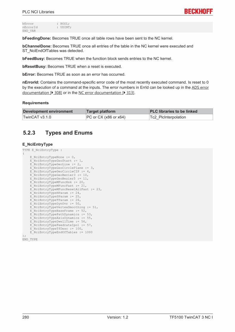
PLC NCI Libraries
TF5100 TwinCAT 3 NC I280 Version: 1.2
bError : BOOL;nErrorId : UDINT;END_VAR
bFeedingDone: Becomes TRUE once all table rows have been sent to the NC kernel.
bChannelDone: Becomes TRUE once all entries of the table in the NC kernel were executed andST_NciEndOfTables was detected.
bFeedBusy: Becomes TRUE when the function block sends entries to the NC kernel.
bResetBusy: Becomes TRUE when a reset is executed.
bError: Becomes TRUE as soon as an error has occurred.
nErrorId: Contains the command-specific error code of the most recently executed command. Is reset to 0by the execution of a command at the inputs. The error numbers in ErrId can be looked up in the ADS errordocumentation [} 308] or in the NC error documentation [} 313].
Requirements
Development environment Target platform PLC libraries to be linkedTwinCAT v3.1.0 PC or CX (x86 or x64) Tc2_PlcInterpolation
5.2.3 Types and Enums
E_NciEntryTypeTYPE E_NciEntryType :( E_NciEntryTypeNone := 0, E_NciEntryTypeGeoStart := 1, E_NciEntryTypeGeoLine := 2, E_NciEntryTypeGeoCirclePlane := 3, E_NciEntryTypeGeoCircleCIP := 4, E_NciEntryTypeGeoBezier3 := 10, E_NciEntryTypeGeoBezier5 := 11, E_NciEntryTypeMFuncHsk := 20, E_NciEntryTypeMFuncFast := 21, E_NciEntryTypeMFuncResetAllFast := 23, E_NciEntryTypeHParam := 24, E_NciEntryTypeSParam := 25, E_NciEntryTypeTParam := 26, E_NciEntryTypeDynOvr := 50, E_NciEntryTypeVertexSmoothing := 51, E_NciEntryTypeBaseFrame := 52, E_NciEntryTypePathDynamics := 53, E_NciEntryTypeAxisDynamics := 55, E_NciEntryTypeDwellTime := 56, E_NciEntryTypeFeedrateIpol := 57, E_NciEntryTypeTfDesc := 100, E_NciEntryTypeEndOfTables := 1000);END_TYPE
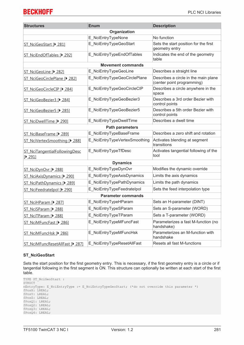
PLC NCI Libraries
TF5100 TwinCAT 3 NC I 281Version: 1.2
Structures Enum DescriptionOrganization
E_NciEntryTypeNone No functionST_NciGeoStart [} 281] E_NciEntryTypeGeoStart Sets the start position for the first
geometry entryST_NciEndOfTables [} 292] E_NciEntryTypeEndOfTables Indicates the end of the geometry
tableMovement commands
ST_NciGeoLine [} 282] E_NciEntryTypeGeoLine Describes a straight line
ST_NciGeoCirclePlane [} 282] E_NciEntryTypeGeoCirclePlane Describes a circle in the main plane(center point programming)
ST_NciGeoCircleCIP [} 284] E_NciEntryTypeGeoCircleCIP Describes a circle anywhere in thespace
ST_NciGeoBezier3 [} 284] E_NciEntryTypeGeoBezier3 Describes a 3rd order Bezier withcontrol points
ST_NciGeoBezier5 [} 285] E_NciEntryTypeGeoBezier5 Describes a 5th order Bezier withcontrol points
ST_NciDwellTime [} 290] E_NciEntryTypeDwellTime Describes a dwell timePath parameters
ST_NciBaseFrame [} 289] E_NciEntryTypeBaseFrame Describes a zero shift and rotation
ST_NciVertexSmoothing [} 288] E_NciEntryTypeVertexSmoothing Activates blending at segmenttransitions
ST_NciTangentialFollowingDesc[} 291]
E_NciEntryTypeTfDesc Activates tangential following of thetool
DynamicsST_NciDynOvr [} 288] E_NciEntryTypeDynOvr Modifies the dynamic override
ST_NciAxisDynamics [} 290] E_NciEntryTypeAxisDynamics Limits the axis dynamics
ST_NciPathDynamics [} 289] E_NciEntryTypePathDynamics Limits the path dynamics
ST_NciFeedrateIpol [} 290] E_NciEntryTypeFeedrateIpol Sets the feed interpolation typeParameter commands
ST_NciHParam [} 287] E_NciEntryTypeHParam Sets an H-parameter (DINT)
ST_NciSParam [} 288] E_NciEntryTypeSParam Sets an S-parameter (WORD)
ST_NciTParam [} 288] E_NciEntryTypeTParam Sets a T-parameter (WORD)
ST_NciMFuncFast [} 286] E_NciEntryTypeMFuncFast Parameterizes a fast M-function (nohandshake)
ST_NciMFuncHsk [} 286] E_NciEntryTypeMFuncHsk Parameterizes an M-function withhandshake
ST_NciMFuncResetAllFast [} 287] E_NciEntryTypeResetAllFast Resets all fast M-functions
ST_NciGeoStart
Sets the start position for the first geometry entry. This is necessary, if the first geometry entry is a circle or iftangential following in the first segment is ON. This structure can optionally be written at each start of the firsttable.TYPE ST_NciGeoStart :STRUCTnEntryType: E_NciEntryType := E_NciEntryTypeGeoStart; (*do not override this parameter *)fPosX: LREAL;fPosY: LREAL;fPosZ: LREAL;fPosQ1: LREAL;fPosQ2: LREAL;fPosQ3: LREAL;fPosQ4: LREAL;
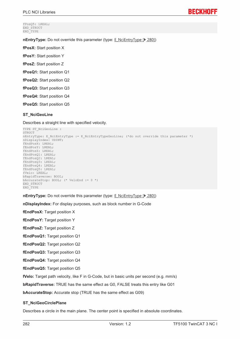
PLC NCI Libraries
TF5100 TwinCAT 3 NC I282 Version: 1.2
fPosQ5: LREAL;END_STRUCTEND_TYPE
nEntryType: Do not override this parameter (type: E_NciEntryType [} 280])
fPosX: Start position X
fPosY: Start position Y
fPosZ: Start position Z
fPosQ1: Start position Q1
fPosQ2: Start position Q2
fPosQ3: Start position Q3
fPosQ4: Start position Q4
fPosQ5: Start position Q5
ST_NciGeoLine
Describes a straight line with specified velocity.TYPE ST_NciGeoLine :STRUCTnEntryType: E_NciEntryType := E_NciEntryTypeGeoLine; (*do not override this parameter *)nDisplayIndex: UDINT;fEndPosX: LREAL;fEndPosY: LREAL;fEndPosZ: LREAL;fEndPosQ1: LREAL;fEndPosQ2: LREAL;fEndPosQ3: LREAL;fEndPosQ4: LREAL;fEndPosQ5: LREAL;fVelo: LREAL;bRapidTraverse: BOOL;bAccurateStop: BOOL; (* VeloEnd := 0 *)END_STRUCTEND_TYPE
nEntryType: Do not override this parameter (type: E_NciEntryType [} 280])
nDisplayIndex: For display purposes, such as block number in G-Code
fEndPosX: Target position X
fEndPosY: Target position Y
fEndPosZ: Target position Z
fEndPosQ1: Target position Q1
fEndPosQ2: Target position Q2
fEndPosQ3: Target position Q3
fEndPosQ4: Target position Q4
fEndPosQ5: Target position Q5
fVelo: Target path velocity, like F in G-Code, but in basic units per second (e.g. mm/s)
bRapidTraverse: TRUE has the same effect as G0, FALSE treats this entry like G01
bAccurateStop: Accurate stop (TRUE has the same effect as G09)
ST_NciGeoCirclePlane
Describes a circle in the main plane. The center point is specified in absolute coordinates.
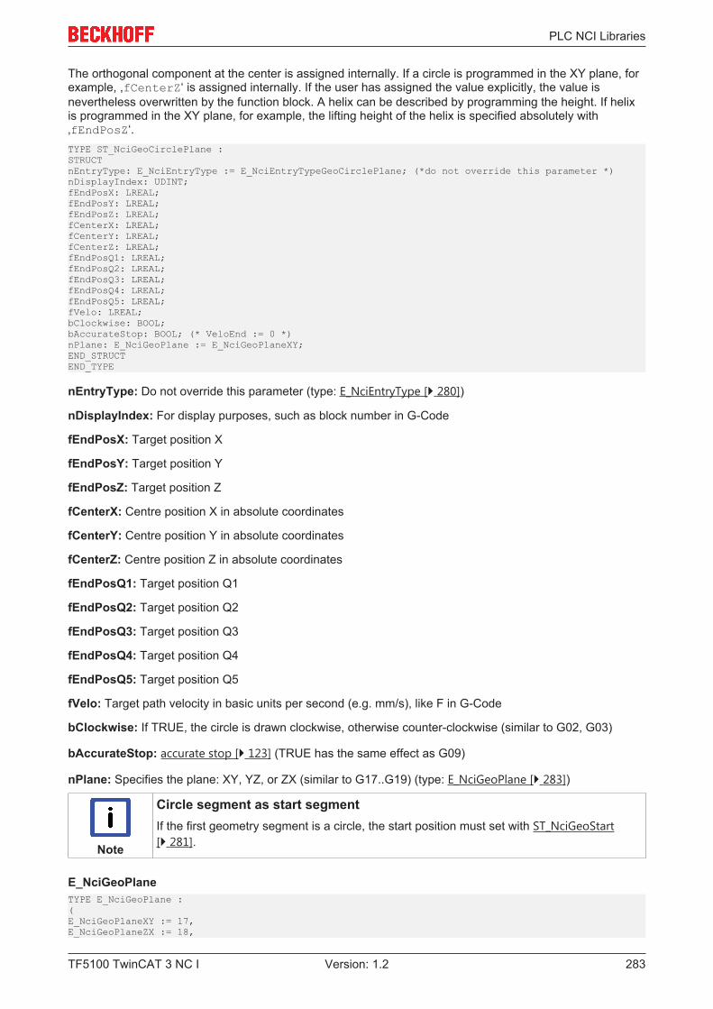
PLC NCI Libraries
TF5100 TwinCAT 3 NC I 283Version: 1.2
The orthogonal component at the center is assigned internally. If a circle is programmed in the XY plane, forexample, ,fCenterZ‘ is assigned internally. If the user has assigned the value explicitly, the value isnevertheless overwritten by the function block. A helix can be described by programming the height. If helixis programmed in the XY plane, for example, the lifting height of the helix is specified absolutely with‚fEndPosZ‘.TYPE ST_NciGeoCirclePlane :STRUCTnEntryType: E_NciEntryType := E_NciEntryTypeGeoCirclePlane; (*do not override this parameter *)nDisplayIndex: UDINT;fEndPosX: LREAL;fEndPosY: LREAL;fEndPosZ: LREAL;fCenterX: LREAL;fCenterY: LREAL;fCenterZ: LREAL;fEndPosQ1: LREAL;fEndPosQ2: LREAL;fEndPosQ3: LREAL;fEndPosQ4: LREAL;fEndPosQ5: LREAL;fVelo: LREAL;bClockwise: BOOL;bAccurateStop: BOOL; (* VeloEnd := 0 *)nPlane: E_NciGeoPlane := E_NciGeoPlaneXY;END_STRUCTEND_TYPE
nEntryType: Do not override this parameter (type: E_NciEntryType [} 280])
nDisplayIndex: For display purposes, such as block number in G-Code
fEndPosX: Target position X
fEndPosY: Target position Y
fEndPosZ: Target position Z
fCenterX: Centre position X in absolute coordinates
fCenterY: Centre position Y in absolute coordinates
fCenterZ: Centre position Z in absolute coordinates
fEndPosQ1: Target position Q1
fEndPosQ2: Target position Q2
fEndPosQ3: Target position Q3
fEndPosQ4: Target position Q4
fEndPosQ5: Target position Q5
fVelo: Target path velocity in basic units per second (e.g. mm/s), like F in G-Code
bClockwise: If TRUE, the circle is drawn clockwise, otherwise counter-clockwise (similar to G02, G03)
bAccurateStop: accurate stop [} 123] (TRUE has the same effect as G09)
nPlane: Specifies the plane: XY, YZ, or ZX (similar to G17..G19) (type: E_NciGeoPlane [} 283])
Note
Circle segment as start segmentIf the first geometry segment is a circle, the start position must set with ST_NciGeoStart[} 281].
E_NciGeoPlaneTYPE E_NciGeoPlane :(E_NciGeoPlaneXY := 17,E_NciGeoPlaneZX := 18,
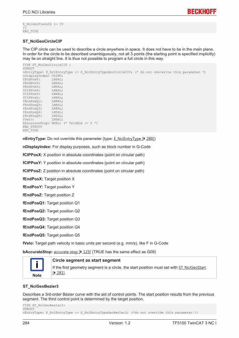
PLC NCI Libraries
TF5100 TwinCAT 3 NC I284 Version: 1.2
E_NciGeoPlaneYZ := 19);END_TYPE
ST_NciGeoCircleCIP
The CIP circle can be used to describe a circle anywhere in space. It does not have to be in the main plane.In order for the circle to be described unambiguously, not all 3 points (the starting point is specified implicitly)may lie on straight line. It is thus not possible to program a full circle in this way.TYPE ST_NciGeoCircleCIP :STRUCTnEntryType: E_NciEntryType := E_NciEntryTypeGeoCircleCIP; (* do not overwrite this parameter *)nDisplayIndex: UDINT;fEndPosX: LREAL;fEndPosY: LREAL;fEndPosZ: LREAL;fCIPPosX: LREAL;fCIPPosY: LREAL;fCIPPosZ: LREAL;fEndPosQ1: LREAL;fEndPosQ2: LREAL;fEndPosQ3: LREAL;fEndPosQ4: LREAL;fEndPosQ5: LREAL;fVelo: LREAL;bAccurateStop: BOOL; (* VeloEnd := 0 *)END_STRUCTEND_TYPE
nEntryType: Do not override this parameter (type: E_NciEntryType [} 280])
nDisplayIndex: For display purposes, such as block number in G-Code
fCIPPosX: X position in absolute coordinates (point on circular path)
fCIPPosY: Y position in absolute coordinates (point on circular path)
fCIPPosZ: Z position in absolute coordinates (point on circular path)
fEndPosX: Target position X
fEndPosY: Target position Y
fEndPosZ: Target position Z
fEndPosQ1: Target position Q1
fEndPosQ2: Target position Q2
fEndPosQ3: Target position Q3
fEndPosQ4: Target position Q4
fEndPosQ5: Target position Q5
fVelo: Target path velocity in basic units per second (e.g. mm/s), like F in G-Code
bAccurateStop: accurate stop [} 123] (TRUE has the same effect as G09)
Note
Circle segment as start segmentIf the first geometry segment is a circle, the start position must set with ST_NciGeoStart[} 281].
ST_NciGeoBezier3
Describes a 3rd-order Bézier curve with the aid of control points. The start position results from the previoussegment. The third control point is determined by the target position.TYPE ST_NciGeoBezier3:STRUCTnEntryType: E_NciEntryType := E_NciEntryTypeGeoBezier3; (*do not override this parameter *)
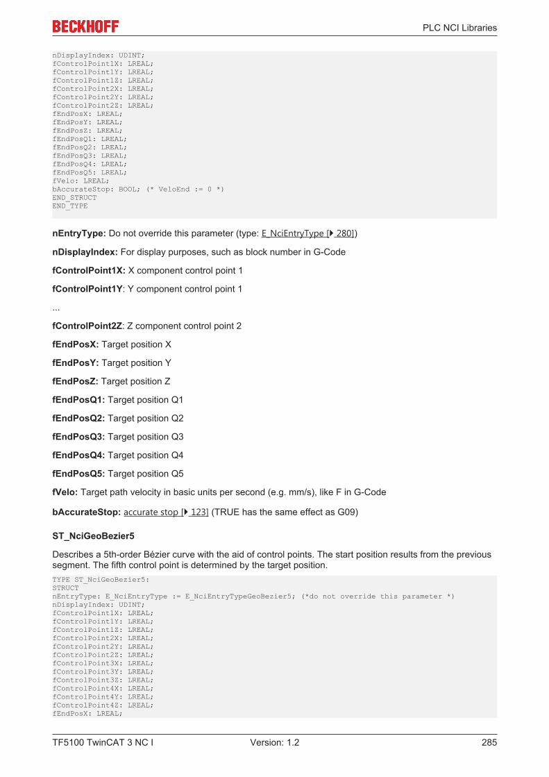
PLC NCI Libraries
TF5100 TwinCAT 3 NC I 285Version: 1.2
nDisplayIndex: UDINT;fControlPoint1X: LREAL;fControlPoint1Y: LREAL;fControlPoint1Z: LREAL;fControlPoint2X: LREAL;fControlPoint2Y: LREAL;fControlPoint2Z: LREAL;fEndPosX: LREAL;fEndPosY: LREAL;fEndPosZ: LREAL;fEndPosQ1: LREAL;fEndPosQ2: LREAL;fEndPosQ3: LREAL;fEndPosQ4: LREAL;fEndPosQ5: LREAL;fVelo: LREAL;bAccurateStop: BOOL; (* VeloEnd := 0 *)END_STRUCTEND_TYPE
nEntryType: Do not override this parameter (type: E_NciEntryType [} 280])
nDisplayIndex: For display purposes, such as block number in G-Code
fControlPoint1X: X component control point 1
fControlPoint1Y: Y component control point 1
...
fControlPoint2Z: Z component control point 2
fEndPosX: Target position X
fEndPosY: Target position Y
fEndPosZ: Target position Z
fEndPosQ1: Target position Q1
fEndPosQ2: Target position Q2
fEndPosQ3: Target position Q3
fEndPosQ4: Target position Q4
fEndPosQ5: Target position Q5
fVelo: Target path velocity in basic units per second (e.g. mm/s), like F in G-Code
bAccurateStop: accurate stop [} 123] (TRUE has the same effect as G09)
ST_NciGeoBezier5
Describes a 5th-order Bézier curve with the aid of control points. The start position results from the previoussegment. The fifth control point is determined by the target position.TYPE ST_NciGeoBezier5:STRUCTnEntryType: E_NciEntryType := E_NciEntryTypeGeoBezier5; (*do not override this parameter *)nDisplayIndex: UDINT;fControlPoint1X: LREAL;fControlPoint1Y: LREAL;fControlPoint1Z: LREAL;fControlPoint2X: LREAL;fControlPoint2Y: LREAL;fControlPoint2Z: LREAL;fControlPoint3X: LREAL;fControlPoint3Y: LREAL;fControlPoint3Z: LREAL;fControlPoint4X: LREAL;fControlPoint4Y: LREAL;fControlPoint4Z: LREAL;fEndPosX: LREAL;

PLC NCI Libraries
TF5100 TwinCAT 3 NC I286 Version: 1.2
fEndPosY: LREAL;fEndPosZ: LREAL;fEndPosQ1: LREAL;fEndPosQ2: LREAL;fEndPosQ3: LREAL;fEndPosQ4: LREAL;fEndPosQ5: LREAL;fVelo: LREAL;bAccurateStop: BOOL; (* VeloEnd := 0 *)END_STRUCTEND_TYPE
nEntryType: Do not override this parameter (type: E_NciEntryType [} 280])
nDisplayIndex: For display purposes, such as block number in G-Code
fControlPoint1X: X component control point 1
fControlPoint1Y: Y component control point 1
...
fControlPoint4Z: Z component control point 4
fEndPosX: Target position X
fEndPosY: Target position Y
fEndPosZ: Target position Z
fEndPosQ1: Target position Q1
fEndPosQ2: Target position Q2
fEndPosQ3: Target position Q3
fEndPosQ4: Target position Q4
fEndPosQ5: Target position Q5
fVelo: Target path velocity in basic units per second (e.g. mm/s), like F in G-Code
bAccurateStop: accurate stop [} 123] (TRUE has the same effect as G09)
ST_NciMFuncHsk
Describes an M-function [} 145] of type handshake. The M-function number is between 0 and 159.TYPE ST_NciMFuncHsk :STRUCTnEntryType: E_NciEntryType := E_NciEntryTypeMFuncHsk; (*do not override this parameter *)nDisplayIndex: UDINT;nMFunc: INT;END_STRUCTEND_TYPE
nEntryType: Do not override this parameter (type: E_NciEntryType [} 280])
nDisplayIndex: For display purposes, such as block number in G-Code
nMFunc: M-function number (0..159)
Note
M-functions in the PlcInterpolation libraryIf M-functions are used in the PlcInterpolation library, they do not have to be entered in theuser interface of the XAE. An M-function always takes effect at the programmed location.
ST_NciMFuncFast
Parameterizes up to 8 fast M-functions [} 145]. The first M-function must be assigned nMFuncIn0, thesecond nMFuncIn1 etc. -1 indicates the end of the assignments.
PLC NCI Libraries
TF5100 TwinCAT 3 NC I 287Version: 1.2
TYPE ST_NciMFuncFast :STRUCTnEntryType: E_NciEntryType := E_NciEntryTypeMFuncFast; (*do not override this parameter *)nDisplayIndex: UDINT;nMFuncIn0: INT;nMFuncIn1: INT;nMFuncIn2: INT;nMFuncIn3: INT;nMFuncIn4: INT;nMFuncIn5: INT;nMFuncIn6: INT;nMFuncIn7: INT;END_STRUCTEND_TYPE
nEntryType: Do not override this parameter (type: E_NciEntryType [} 280])
nDisplayIndex: For display purposes, such as block number in G-Code
nMFuncIn0: fast M-function number (0..159)
nMFuncIn1: Fast M-function number (0..159); -1 indicates the end of the list.
nMFuncIn2: Fast M-function number (0..159); -1 indicates the end of the list.
nMFuncIn3: Fast M-function number (0..159); -1 indicates the end of the list.
nMFuncIn4: Fast M-function number (0..159); -1 indicates the end of the list.
nMFuncIn5: Fast M-function number (0..159); -1 indicates the end of the list.
nMFuncIn6: Fast M-function number (0..159); -1 indicates the end of the list.
nMFuncIn7: Fast M-function number (0..159); -1 indicates the end of the list.
Note
M-functions in the PlcInterpolation libraryIf M-functions are used in the PlcInterpolation library, they do not have to be entered in theuser interface of the XAE. An M-function always takes effect at the programmed location.
ST_NciMFuncResetAllFast
Resets all fast M-functions [} 145].TYPE ST_NciMFuncResetAllFast :STRUCTnEntryType: E_NciEntryType := E_NciEntryTypeMFuncResetAllFast; (*do not override this parameter *)nDisplayIndex: UDINT;END_STRUCTEND_TYPE
nEntryType: Do not override this parameter (type: E_NciEntryType [} 280])
nDisplayIndex: For display purposes, such as block number in G-Code
ST_NciHParam
Sets an H-parameter [} 149] in the cyclic channel interface.TYPE ST_NciHParam :STRUCTnEntryType: E_NciEntryType := E_NciEntryTypeHParam; (*do not override this parameter *)nDisplayIndex: UDINT;nHParam: UDINT;END_STRUCTEND_TYPE
nEntryType: Do not override this parameter (type: E_NciEntryType [} 280])
nDisplayIndex: For display purposes, such as block number in G-Code
nHParam: H-parameter from NC to PLC
PLC NCI Libraries
TF5100 TwinCAT 3 NC I288 Version: 1.2
ST_NciSParam
Sets an S-parameter [} 149] in the cyclic channel interface.TYPE ST_NciSParam :STRUCTnEntryType: E_NciEntryType := E_NciEntryTypeSParam; (*do not override this parameter *)nDisplayIndex: UDINT;nSParam: UINT;END_STRUCTEND_TYPE
nEntryType: Do not override this parameter (type: E_NciEntryType [} 280])
nDisplayIndex: For display purposes, such as block number in G-Code
nSParam: S-parameter from NC to PLC
ST_NciTParam
Sets an T-parameter [} 149] in the cyclic channel interface.TYPE ST_NciTParam :STRUCTnEntryType: E_NciEntryType := E_NciEntryTypeTParam; (*do not override this parameter *)nDisplayIndex: UDINT;nTParam: UINT;END_STRUCTEND_TYPE
nEntryType: Do not override this parameter (type: E_NciEntryType [} 280])
nDisplayIndex: For display purposes, such as block number in G-Code
nTParam: T-parameter from NC to PLC
ST_NciDynOvr
Modal functions for changing the path dynamics.
See DynOvr [} 156] in the interpreter documentation [} 107].TYPE ST_NciDynOvr :STRUCTnEntryType: E_NciEntryType := E_NciEntryTypeDynOvr; (*do not override this parameter*)nDisplayIndex: UDINT;fDynOvr: LREAL;END_STRUCTEND_TYPE
nEntryType: Do not override this parameter (type: E_NciEntryType [} 280])
nDisplayIndex: For display purposes, such as block number in G-Code
fDynOvr: Value for dynamic override (1 < fDynOvr <= 1)
ST_NciVertexSmoothing
Modal function for activating blending at the segment transition. Blending is active until it is cancelled bysetting the radius to 0.
A more detailed description of the parameter can be found in the interpreter documentation [} 107].(paramVertexSmoothing [} 133]).TYPE ST_NciVertexSmoothing :STRUCTnEntryType: E_NciEntryType := E_NciEntryTypeVertexSmoothing; (*do not override this parameter *)nDisplayIndex: UDINT;nType: UDINT; (*type of smoothing, e.g. parabola, bi-quad *)nSubtype: UDINT; (*e.g. adaptive, constant radius *)fRadius: LREAL; (*max. radius for tolerance ball *)END_STRUCTEND_TYPE
PLC NCI Libraries
TF5100 TwinCAT 3 NC I 289Version: 1.2
nEntryType: Do not override this parameter (type: E_NciEntryType [} 280])
nDisplayIndex: For display purposes, such as block number in G-Code
nType: Blending type: 2: parabola, 3: Bi-quadratic, 4: Bezier 3rd order, 5: 5th order Bezier
nSubtype: 1: constant tolerance radius, 2: distance between intersection and vertex, 3: Adaptive toleranceradius
fRadius: Radius of the blending sphere in basic units (e.g. mm)
ST_NciBaseFrame
The structure ST_NciBaseFrame describes a modal zero shift and rotation. The operating principle is thesame as for zero shift and rotation in the interpreter, i.e. the point of rotation is the current origin (seerotation [} 129] in the interpreter documentation [} 107]).TYPE ST_NciBaseFrame:STRUCTnEntryType: E_NciEntryType := E_NciEntryTypeBaseFrame; (*Do not override this parameter *)nDisplayIndex: UDINT;fShiftX: LREAL;fShiftY: LREAL;fShiftZ: LREAL;fRotX: LREAL;fRotY: LREAL;fRotZ: LREAL;fShiftQ1: LREAL;fShiftQ2: LREAL;fShiftQ3: LREAL;fShiftQ4: LREAL;fShiftQ5: LREAL;END_STRUCTEND_TYPE
nEntryType: Do not override this parameter (type: E_NciEntryType [} 280])
nDisplayIndex: For display purposes, such as block number in G-Code
fShiftX: Zero shift in X direction
fShiftY: Zero shift in Y direction
fShiftZ: Zero shift in Z direction
fRotX: Rotation of the X axis
fRotY: Rotation of the Y axis
fRotZ: Rotation of the Z axis
fShiftQ1: Offset of the Q1 axis
fShfitQ2: Offset of the Q2-axis
fShiftQ3: Offset of the Q3-axis
fShiftQ4: Offset of the Q4-axis
fShiftQ5: Offset of the Q5-axis
ST_NciPathDynamics
The structure ST_NciPathDynamics sets the path dynamics (acceleration, deceleration, jerk). The operatingprinciple is the same as for paramPathDynamics in the interpreter (see paramPathDynamics [} 156] in theinterpreter documentation [} 107]).TYPE ST_NciPathDynamics:STRUCTnEntryType: E_NciEntryType := E_NciEntryTypePathDynamics; (*do not override this parameter *)nDisplayIndex: UDINT;fAcc: LREAL;

PLC NCI Libraries
TF5100 TwinCAT 3 NC I290 Version: 1.2
fDec: LREAL;fJerk: LREAL;END_STRUCTEND_TYPE
nEntryType: Do not override this parameter (type: E_NciEntryType [} 280])
nDisplayIndex: For display purposes, such as block number in G-Code
fAcc: Maximum permitted path acceleration
fDec: Maximum permitted path deceleration
fJerk: Maximum permitted path jerk
ST_NciAxisDynamics
The structure ST_NciAxisDynamics sets the path axis dynamics (acceleration, deceleration, jerk). Theoperating principle is the same as for paramAxisDynamics in the interpreter (see paramAxisDynamics [} 156]in the interpreter documentation [} 107])TYPE ST_NciAxisDynamics:STRUCTnEntryType: E_NciEntryType := E_NciEntryTypeAxisDynamics; (*Do not override this parameter*)nDisplayIndex: UDINT;nAxis: UDINT;fAcc: LREAL;fDec: LREAL;fJerk: LREAL;END_STRUCTEND_TYPE
nEntryType: Do not override this parameter (type: E_NciEntryType [} 280])
nDisplayIndex: For display purposes, such as block number in G-Code
nAxis: Axis in interpolation group X:0 Y:1 Z:2 Q1:3 ... Q5:7
fAcc: Maximum permitted axis acceleration
fDec: Maximum permitted axis deceleration
fJerk: Maximum permitted axis jerk
ST_NciDwellTime
The structure ST_NciDwellTime is used to activate a dwell time in seconds (see dwell time [} 122] in theinterpreter documentation [} 107])TYPE ST_NciDwellTime:STRUCTnEntryType: E_NciEntryType := E_NciEntryTypeDwellTime; (*Do not override this parameter *)nDisplayIndex: UDINT;fDwellTime: LREAL;END_STRUCTEND_TYPE
nEntryType: Do not override this parameter (type: E_NciEntryType [} 280])
nDisplayIndex: For display purposes, such as block number in G-Code
fDwellTime: Dwell time in seconds
ST_NciFeedrateIpol
The structure ST_NciFeedrateIpol can be used to set the feed interpolation (see Feed interpolation [} 123]).TYPE ST_NciFeedrateIpol :STRUCTnEntryType: E_NciEntryType := E_NciEntryTypeFeedrateIpol;(*Do not overwrite this parameter*)nDisplayIndex: UDINT;eFeedrateIpol: E_NciFeedrateIpol;(*E_NciFeedrateIpolConstant = FCONST, E_NciFeedrateIpolLinear=FLIN
PLC NCI Libraries
TF5100 TwinCAT 3 NC I 291Version: 1.2
*)END_STRUCTEND_TYPE
nEntryType: Do not override this parameter (type: E_NciEntryType [} 280])
eFeedrateIpol: specifies the feed interpolation.TYPE E_NciFeedRateIpol :(E_NciFeedrateIpolConstant,E_NciFeedrateIpolLinear)END_TYPE
ST_NciTangentialFollowingDesc
This is a modal command for switching tangential following on or off.TYPE ST_NciTangentialFollowingDesc :STRUCTnEntryType: E_NciEntryType := E_NciEntryTypeTfDesc; (*do not override this parameter *)bTangOn: BOOL;nTangAxis: E_NciAxesInGroup; (*axis used for tangential following *)nPathAxis1: E_NciAxesInGroup; (*describing the plane e.g. x*)nPathAxis2: E_NciAxesInGroup; (*e.g. y ==> g17, xy plane*)fOffset: LREAL; (*geo tangent is 0 degree, counting is mathmatical positive *)fCriticalAngle1: LREAL;nTfBehavior: E_TangentialFollowingBehavior; (*what to do if angle becomes bigger than critical angle1 *)END_STRUCTEND_TYPE
nEntryType: Do not override this parameter (type: E_NciEntryType [} 280])
bTangOn: If TRUE, tangential following is switched on.
nTangAxis: Axis (Q1..Q5) that is used as tangential axis (type: E_NciAxesInGroup [} 291]).
nPathAxis1: First path axis describing the plane and orientation for calculating the tangent.
nPathAxis2: Second path axis describing the plane and orientation for calculating the tangent.
fOffset: Offset of the tangential axis
fCriticalAngle1: Critical angle 1. The response in cases where the angle between two segments is greaterthan fCriticalAngle1 is specified with nTfBehavior.
nTfBehavior: see fCriticalAngle1 (type: E_TangentialFollowingBehavior [} 291])
E_NciAxesInGroupTYPE E_NciAxesInGroup :(NoneAxis := 0,XAxis,YAxis,ZAxis,Q1Axis,Q2Axis,Q3Axis,Q4Axis,Q5Axis);END_TYPE
E_TangentialFollowingBehaviorTYPE E_TangentialFollowingBehavior :(E_TfIngoreAll, (*ignore critical angle *)E_TfErrorOnCritical1 (*if angle becomes bigger than critical angle 1 ==> error *));END_TYPE
E_TfIngoreAll: The critical angle is ignored.
PLC NCI Libraries
TF5100 TwinCAT 3 NC I292 Version: 1.2
E_TfErrorOnCritical1: An error is returned if the critical angle is exceeded.
ST_NciEndOfTables
Indicates the last entry of the last table. Is used for signaling the bChannelDone flag in FB_NciFeedTable[} 279].TYPE ST_NciEndOfTables :STRUCTnEntryType: E_NciEntryType := E_NciEntryTypeEndOfTables; (*do not override this parameter *)END_STRUCTEND_TYPE
nEntryType: Do not override this parameter (type: E_NciEntryType [} 280])

Samples
TF5100 TwinCAT 3 NC I 293Version: 1.2
6 SamplesNCI: NCISimpleSample
Download:
https://infosys.beckhoff.com/content/1033/TF5100_TC3_NC_I/Resources/zip/9007202693487883.zip
The example NCISimpleSample shows how an G-Code program is loaded from the PLC and processing isstarted.
You need to copy the enclosed parts program TestIt.nc into the TwinCAT\Mc\Nci directory. Otherwise theparts program will not be found during loading. Alternatively you can adjust the path in the PLC program.
PLC interpolation: PlcInterpolationSimpleSample
Download:
https://infosys.beckhoff.com/content/1033/TF5100_TC3_NC_I/Resources/zip/18014401453622155.zip
The sample shows how a movement can be affected with the library Tc2_PlcInterpolation directly from thePLC.
Appendix
TF5100 TwinCAT 3 NC I294 Version: 1.2
7 Appendix
7.1 Display of the parts program
Reading of the current NC line via ADS
This ADS Read command returns a maximum of three lines of the current parts program, i.e. the current lineof code and perhaps two previously processed lines.
Function ADS-ReadPort 500 (dec)Index Group 0x2300 + channel IDIndex Offset 0x2000 0001Data string (30 bytes min.)
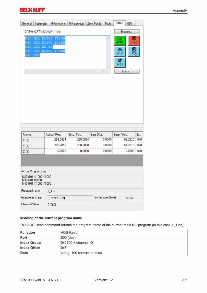
Appendix
TF5100 TwinCAT 3 NC I 295Version: 1.2
Reading of the current program name
This ADS Read command returns the program name of the current main NC program (in this case 1_1.nc).
Function ADS-ReadPort 500 (dec)Index Group 0x2100 + channel IDIndex Offset 0x7Data string, 100 characters max.
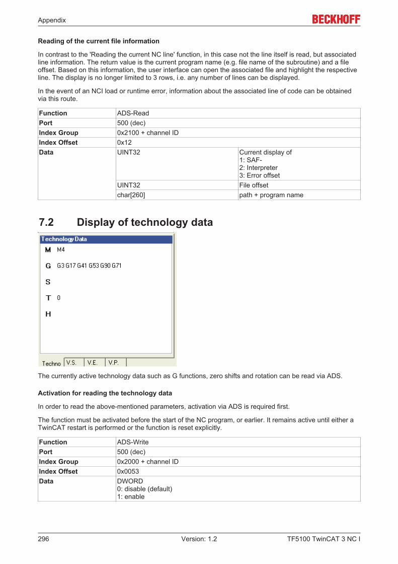
Appendix
TF5100 TwinCAT 3 NC I296 Version: 1.2
Reading of the current file information
In contrast to the 'Reading the current NC line' function, in this case not the line itself is read, but associatedline information. The return value is the current program name (e.g. file name of the subroutine) and a fileoffset. Based on this information, the user interface can open the associated file and highlight the respectiveline. The display is no longer limited to 3 rows, i.e. any number of lines can be displayed.
In the event of an NCI load or runtime error, information about the associated line of code can be obtainedvia this route.
Function ADS-ReadPort 500 (dec)Index Group 0x2100 + channel IDIndex Offset 0x12Data UINT32 Current display of
1: SAF-2: Interpreter3: Error offset
UINT32 File offsetchar[260] path + program name
7.2 Display of technology data
The currently active technology data such as G functions, zero shifts and rotation can be read via ADS.
Activation for reading the technology data
In order to read the above-mentioned parameters, activation via ADS is required first.
The function must be activated before the start of the NC program, or earlier. It remains active until either aTwinCAT restart is performed or the function is reset explicitly.
Function ADS-WritePort 500 (dec)Index Group 0x2000 + channel IDIndex Offset 0x0053Data DWORD
0: disable (default)1: enable
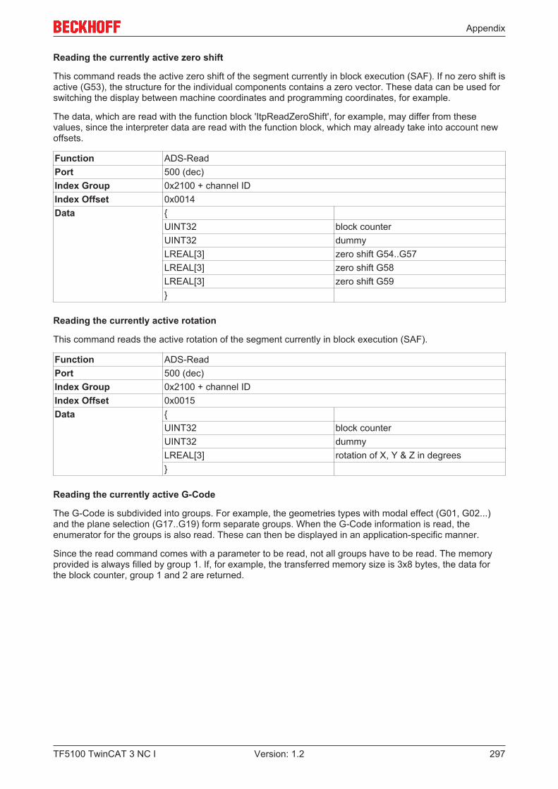
Appendix
TF5100 TwinCAT 3 NC I 297Version: 1.2
Reading the currently active zero shift
This command reads the active zero shift of the segment currently in block execution (SAF). If no zero shift isactive (G53), the structure for the individual components contains a zero vector. These data can be used forswitching the display between machine coordinates and programming coordinates, for example.
The data, which are read with the function block 'ItpReadZeroShift', for example, may differ from thesevalues, since the interpreter data are read with the function block, which may already take into account newoffsets.
Function ADS-ReadPort 500 (dec)Index Group 0x2100 + channel IDIndex Offset 0x0014Data {
UINT32 block counterUINT32 dummyLREAL[3] zero shift G54..G57LREAL[3] zero shift G58LREAL[3] zero shift G59}
Reading the currently active rotation
This command reads the active rotation of the segment currently in block execution (SAF).
Function ADS-ReadPort 500 (dec)Index Group 0x2100 + channel IDIndex Offset 0x0015Data {
UINT32 block counterUINT32 dummyLREAL[3] rotation of X, Y & Z in degrees}
Reading the currently active G-Code
The G-Code is subdivided into groups. For example, the geometries types with modal effect (G01, G02...)and the plane selection (G17..G19) form separate groups. When the G-Code information is read, theenumerator for the groups is also read. These can then be displayed in an application-specific manner.
Since the read command comes with a parameter to be read, not all groups have to be read. The memoryprovided is always filled by group 1. If, for example, the transferred memory size is 3x8 bytes, the data forthe block counter, group 1 and 2 are returned.
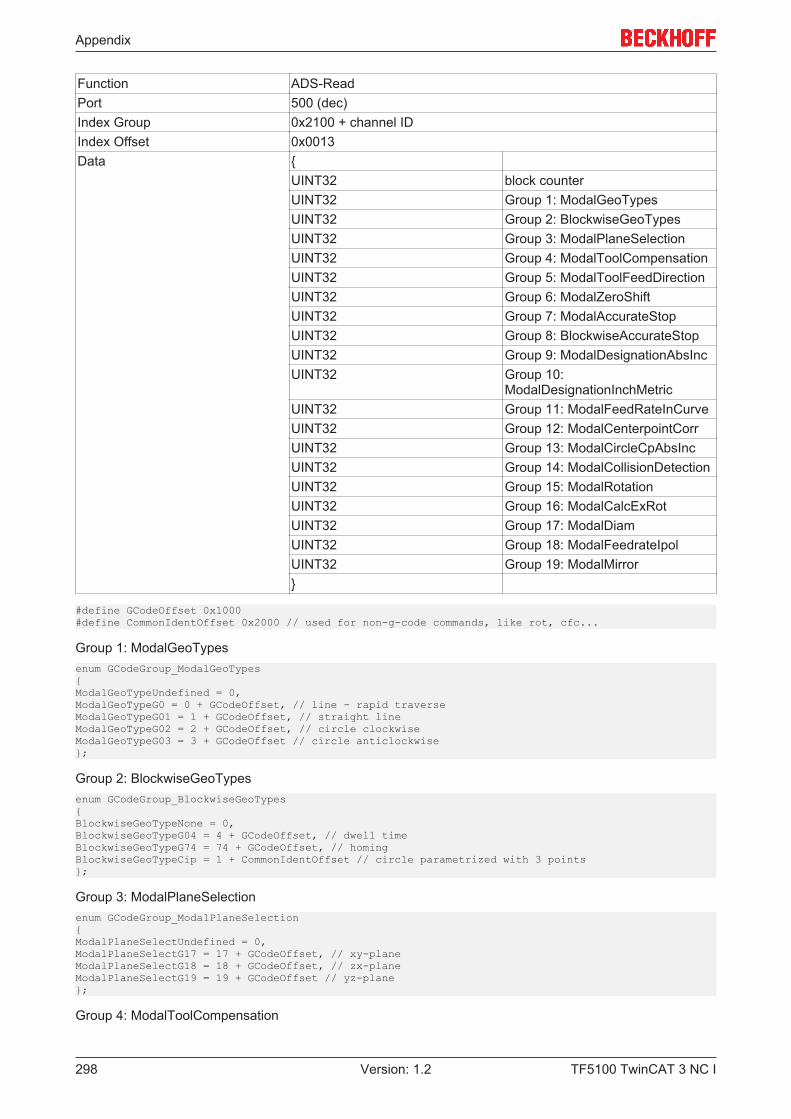
Appendix
TF5100 TwinCAT 3 NC I298 Version: 1.2
Function ADS-ReadPort 500 (dec)Index Group 0x2100 + channel IDIndex Offset 0x0013Data {
UINT32 block counterUINT32 Group 1: ModalGeoTypesUINT32 Group 2: BlockwiseGeoTypesUINT32 Group 3: ModalPlaneSelectionUINT32 Group 4: ModalToolCompensationUINT32 Group 5: ModalToolFeedDirectionUINT32 Group 6: ModalZeroShiftUINT32 Group 7: ModalAccurateStopUINT32 Group 8: BlockwiseAccurateStopUINT32 Group 9: ModalDesignationAbsIncUINT32 Group 10:
ModalDesignationInchMetricUINT32 Group 11: ModalFeedRateInCurveUINT32 Group 12: ModalCenterpointCorrUINT32 Group 13: ModalCircleCpAbsIncUINT32 Group 14: ModalCollisionDetectionUINT32 Group 15: ModalRotationUINT32 Group 16: ModalCalcExRotUINT32 Group 17: ModalDiamUINT32 Group 18: ModalFeedrateIpolUINT32 Group 19: ModalMirror}
#define GCodeOffset 0x1000#define CommonIdentOffset 0x2000 // used for non-g-code commands, like rot, cfc...
Group 1: ModalGeoTypesenum GCodeGroup_ModalGeoTypes{ModalGeoTypeUndefined = 0,ModalGeoTypeG0 = 0 + GCodeOffset, // line - rapid traverseModalGeoTypeG01 = 1 + GCodeOffset, // straight lineModalGeoTypeG02 = 2 + GCodeOffset, // circle clockwiseModalGeoTypeG03 = 3 + GCodeOffset // circle anticlockwise};
Group 2: BlockwiseGeoTypesenum GCodeGroup_BlockwiseGeoTypes{BlockwiseGeoTypeNone = 0,BlockwiseGeoTypeG04 = 4 + GCodeOffset, // dwell timeBlockwiseGeoTypeG74 = 74 + GCodeOffset, // homingBlockwiseGeoTypeCip = 1 + CommonIdentOffset // circle parametrized with 3 points};
Group 3: ModalPlaneSelectionenum GCodeGroup_ModalPlaneSelection{ModalPlaneSelectUndefined = 0,ModalPlaneSelectG17 = 17 + GCodeOffset, // xy-planeModalPlaneSelectG18 = 18 + GCodeOffset, // zx-planeModalPlaneSelectG19 = 19 + GCodeOffset // yz-plane};
Group 4: ModalToolCompensation
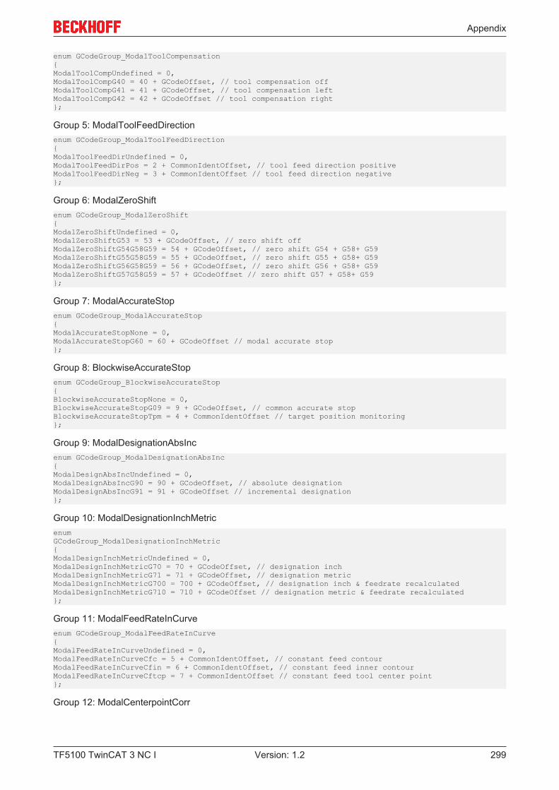
Appendix
TF5100 TwinCAT 3 NC I 299Version: 1.2
enum GCodeGroup_ModalToolCompensation{ModalToolCompUndefined = 0,ModalToolCompG40 = 40 + GCodeOffset, // tool compensation offModalToolCompG41 = 41 + GCodeOffset, // tool compensation leftModalToolCompG42 = 42 + GCodeOffset // tool compensation right};
Group 5: ModalToolFeedDirectionenum GCodeGroup_ModalToolFeedDirection{ModalToolFeedDirUndefined = 0,ModalToolFeedDirPos = 2 + CommonIdentOffset, // tool feed direction positiveModalToolFeedDirNeg = 3 + CommonIdentOffset // tool feed direction negative};
Group 6: ModalZeroShiftenum GCodeGroup_ModalZeroShift{ModalZeroShiftUndefined = 0,ModalZeroShiftG53 = 53 + GCodeOffset, // zero shift offModalZeroShiftG54G58G59 = 54 + GCodeOffset, // zero shift G54 + G58+ G59ModalZeroShiftG55G58G59 = 55 + GCodeOffset, // zero shift G55 + G58+ G59ModalZeroShiftG56G58G59 = 56 + GCodeOffset, // zero shift G56 + G58+ G59ModalZeroShiftG57G58G59 = 57 + GCodeOffset // zero shift G57 + G58+ G59};
Group 7: ModalAccurateStopenum GCodeGroup_ModalAccurateStop{ModalAccurateStopNone = 0,ModalAccurateStopG60 = 60 + GCodeOffset // modal accurate stop};
Group 8: BlockwiseAccurateStopenum GCodeGroup_BlockwiseAccurateStop{BlockwiseAccurateStopNone = 0,BlockwiseAccurateStopG09 = 9 + GCodeOffset, // common accurate stopBlockwiseAccurateStopTpm = 4 + CommonIdentOffset // target position monitoring};
Group 9: ModalDesignationAbsIncenum GCodeGroup_ModalDesignationAbsInc{ModalDesignAbsIncUndefined = 0,ModalDesignAbsIncG90 = 90 + GCodeOffset, // absolute designationModalDesignAbsIncG91 = 91 + GCodeOffset // incremental designation};
Group 10: ModalDesignationInchMetricenumGCodeGroup_ModalDesignationInchMetric{ModalDesignInchMetricUndefined = 0,ModalDesignInchMetricG70 = 70 + GCodeOffset, // designation inchModalDesignInchMetricG71 = 71 + GCodeOffset, // designation metricModalDesignInchMetricG700 = 700 + GCodeOffset, // designation inch & feedrate recalculatedModalDesignInchMetricG710 = 710 + GCodeOffset // designation metric & feedrate recalculated};
Group 11: ModalFeedRateInCurveenum GCodeGroup_ModalFeedRateInCurve{ModalFeedRateInCurveUndefined = 0,ModalFeedRateInCurveCfc = 5 + CommonIdentOffset, // constant feed contourModalFeedRateInCurveCfin = 6 + CommonIdentOffset, // constant feed inner contourModalFeedRateInCurveCftcp = 7 + CommonIdentOffset // constant feed tool center point};
Group 12: ModalCenterpointCorr

Appendix
TF5100 TwinCAT 3 NC I300 Version: 1.2
enum GCodeGroup_ModalCenterpointCorr{ModalCenterpointCorrUndefined = 0,ModalCenterpointCorrOn = 8 + CommonIdentOffset, // circle centerpoint correction onModalCenterpointCorrOff = 9 + CommonIdentOffset // circle centerpoint correction off};
Group 13: ModalCircleCpAbsIncenum GCodeGroup_ModalCircleCpAbsInc{ModalCircleCpUndefined = 0,ModalCircleCpIncremental = 10 + CommonIdentOffset, // circle centerpoint incremental to start pointModalCircleCpAbsolute = 11 + CommonIdentOffset // circle centerpoint absolute};
Group 14: ModalCollisionDetectionenum GCodeGroup_ModalCollisionDetection{ModalCollisionDetectionUndefined = 0,ModalCollisionDetectionOn = 12 + CommonIdentOffset, //collision detection onModalCollisionDetectionOff = 13 + CommonIdentOffset //collision detection off};
Group 15: ModalRotationenum GCodeGroup_ModalRotation{ModalRotationUndefined = 0,ModalRotationOn = 14 + CommonIdentOffset, // rotation is turned onModalRotationOff = 15 + CommonIdentOffset // rotation is turned off};
Group 16: ModalCalcExRotenum GCodeGroup_ModalCalcExRot{ModalCalcExRotUndefined = 0,ModalCalcExRotOn = 16 + CommonIdentOffset, // extended calculation for rotation turned onModalCalcExRotOff = 17 + CommonIdentOffset // extended calculation for rotation turned off};
Group 17: ModalDiamenum GCodeGroup_ModalDiam{ModalDiamUndefined = 0,ModalDiamOn = 18 + CommonIdentOffset, // diameter programming onModalDiamOff = 19 + CommonIdentOffset // diameter programming off};
Group 18: ModalFeedrateIpolenum GCodeGroup_ModalFeedrateIpol{ModalFeedrateIpolUndefined = 0,ModalFeedrateIpolConst = 20 + CommonIdentOffset, // federate interpolation constant (default)ModalFeedrateIpolLinear = 21 + CommonIdentOffset // federate interpoaltion linear to remaining path};
Group 19: ModalMirrorenum GCodeGroup_ModalMirror{// value - (32+CommonIdentOffset) shows the bitmask for mirrored axes// that's why the sequence seems to be strange...//ModalMirrorUndefined = 0,ModalMirrorOff = 32 + CommonIdentOffset,ModalMirrorX = 33 + CommonIdentOffset,ModalMirrorY = 34 + CommonIdentOffset,ModalMirrorXY = 35 + CommonIdentOffset,ModalMirrorZ = 36 + CommonIdentOffset,ModalMirrorZX = 37 + CommonIdentOffset,ModalMirrorYZ = 38 + CommonIdentOffset,ModalMirrorXYZ = 39 + CommonIdentOffset};
Appendix
TF5100 TwinCAT 3 NC I 301Version: 1.2
7.3 Displaying the remaining path lengthIf calculation of the remaining path length is switched active, it is calculated up to as far as the next accuratestop, or as far as the last geometric segment in memory (block preparation). An accurate stop is, forinstance, generated by G09 or by G60. However, M-functions of type handshake, decoder stops and G04implicitly generate an accurate stop.
Activation:
Index Group: 0x3000 + Group IDIndex Offset: 0x0508
see index offset specification for group parameters [} 391]
Reading the remaining path length:Reading is again implemented through ADS, and can also be recorded with TwinCAT Scope.
Index Group: 0x3100 + Group IDIndex Offset: 0x0522
The remaining path length can be transferred with the cyclic channel interface to the PLC viaItpSetCyclicLrealOffsets [} 220].see index offset specification for group state [} 396]
7.4 ParameterisationThe parameterization of the NCI comprises the standard dynamic parameters (acceleration, deceleration,jerk) and their online changes, along with the minimum velocity and the parameters for the reduction of thepath velocity including online change.
General characteristics at segment transitions• Velocity: The segment set velocity VS changes at the segment transition from VS_in to VS_out. At the
segment transition the velocity is always reduced to the lower of the two values.• Acceleration: The current path acceleration is always returned to a = 0 at segment transition.• Jerk: The jerk unit J changes according to the geometry at the segment transition. This can cause a
significant step change in dynamics.
• It is possible to smooth segment transitions [} 110].
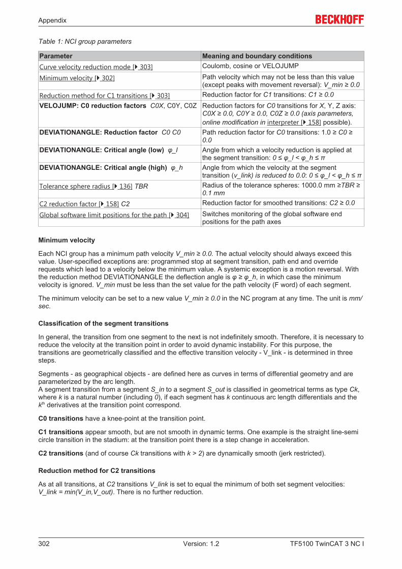
Appendix
TF5100 TwinCAT 3 NC I302 Version: 1.2
Table 1: NCI group parameters
Parameter Meaning and boundary conditionsCurve velocity reduction mode [} 303] Coulomb, cosine or VELOJUMP
Minimum velocity [} 302] Path velocity which may not be less than this value(except peaks with movement reversal): V_min ≥ 0.0
Reduction method for C1 transitions [} 303] Reduction factor for C1 transitions: C1 ≥ 0.0VELOJUMP: C0 reduction factors C0X, C0Y, C0Z Reduction factors for C0 transitions for X, Y, Z axis:
C0X ≥ 0.0, C0Y ≥ 0.0, C0Z ≥ 0.0 (axis parameters,online modification in interpreter [} 158] possible).
DEVIATIONANGLE: Reduction factor C0 C0 Path reduction factor for C0 transitions: 1.0 ≥ C0 ≥0.0
DEVIATIONANGLE: Critical angle (low) φ_l Angle from which a velocity reduction is applied atthe segment transition: 0 ≤ φ_l < φ_h ≤ π
DEVIATIONANGLE: Critical angle (high) φ_h Angle from which the velocity at the segmenttransition (v_link) is reduced to 0.0: 0 ≤ φ_l < φ_h ≤ π
Tolerance sphere radius [} 136] TBR Radius of the tolerance spheres: 1000.0 mm ≥TBR ≥0.1 mm
C2 reduction factor [} 158] C2 Reduction factor for smoothed transitions: C2 ≥ 0.0
Global software limit positions for the path [} 304] Switches monitoring of the global software endpositions for the path axes
Minimum velocity
Each NCI group has a minimum path velocity V_min ≥ 0.0. The actual velocity should always exceed thisvalue. User-specified exceptions are: programmed stop at segment transition, path end and overriderequests which lead to a velocity below the minimum value. A systemic exception is a motion reversal. Withthe reduction method DEVIATIONANGLE the deflection angle is φ ≥ φ_h, in which case the minimumvelocity is ignored. V_min must be less than the set value for the path velocity (F word) of each segment.
The minimum velocity can be set to a new value V_min ≥ 0.0 in the NC program at any time. The unit is mm/sec.
Classification of the segment transitions
In general, the transition from one segment to the next is not indefinitely smooth. Therefore, it is necessary toreduce the velocity at the transition point in order to avoid dynamic instability. For this purpose, thetransitions are geometrically classified and the effective transition velocity - V_link - is determined in threesteps.
Segments - as geographical objects - are defined here as curves in terms of differential geometry and areparameterized by the arc length.A segment transition from a segment S_in to a segment S_out is classified in geometrical terms as type Ck,where k is a natural number (including 0), if each segment has k continuous arc length differentials and thekth derivatives at the transition point correspond.
C0 transitions have a knee-point at the transition point.
C1 transitions appear smooth, but are not smooth in dynamic terms. One example is the straight line-semicircle transition in the stadium: at the transition point there is a step change in acceleration.
C2 transitions (and of course Ck transitions with k > 2) are dynamically smooth (jerk restricted).
Reduction method for C2 transitions
As at all transitions, at C2 transitions V_link is set to equal the minimum of both set segment velocities:V_link = min(V_in,V_out). There is no further reduction.
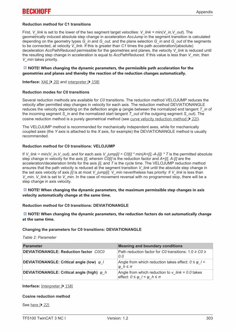
Appendix
TF5100 TwinCAT 3 NC I 303Version: 1.2
Reduction method for C1 transitions
First, V_link is set to the lower of the two segment target velocities: V_link = min(V_in,V_out). Thegeometrically induced absolute step change in acceleration AccJump in the segment transition is calculateddepending on the geometry types G_in and G_out, and the plane selection G_in and G_out of the segmentsto be connected, at velocity V_link. If this is greater than C1 times the path acceleration/(absolute)deceleration AccPathReduced permissible for the geometries and planes, the velocity V_link is reduced untilthe resulting step change in acceleration is equal to AccPathReduced. If this value is less than V_min, thenV_min takes priority.
NOTE! When changing the dynamic parameters, the permissible path acceleration for thegeometries and planes and thereby the reaction of the reduction changes automatically.
Interface: XAE [} 20] and interpreter [} 158]
Reduction modes for C0 transitions
Several reduction methods are available for C0 transitions. The reduction method VELOJUMP reduces thevelocity after permitted step changes in velocity for each axis. The reduction method DEVIATIONANGLEreduces the velocity depending on the deflection angle φ (angle between the normalized end tangent T_in ofthe incoming segment S_in and the normalized start tangent T_out of the outgoing segment S_out). Thecosine reduction method is a purely geometrical method (see curve velocity reduction method [} 22]).
The VELOJUMP method is recommended for mechanically independent axes, while for mechanicallycoupled axes (the Y axis is attached to the X axis, for example) the DEVIATIONANGLE method is usuallyrecommended.
Reduction method for C0 transitions: VELOJUMP
If V_link = min(V_in,V_out), and for each axis V_jump[i] = C0[i] * min(A+[i],-A-[i]) * T is the permitted absolutestep change in velocity for the axis [i], wherein C0[i] is the reduction factor and A+[i], A-[i] are theacceleration/deceleration limits for the axis [i], and T is the cycle time. The VELOJUMP reduction methodensures that the path velocity is reduced at the segment transition V_link until the absolute step change inthe set axis velocity of axis [i] is at most V_jump[i]. V_min nevertheless has priority: if V_link is less thanV_min, V_link is set to V_min. In the case of movement reversal with no programmed stop, there will be astep change in axis velocity.
NOTE! When changing the dynamic parameters, the maximum permissible step changes in axisvelocity automatically change at the same time.
Reduction method for C0 transitions: DEVIATIONANGLE
NOTE! When changing the dynamic parameters, the reduction factors do not automatically changeat the same time.
Changing the parameters for C0 transitions: DEVIATIONANGLE
Table 2: Parameter
Parameter Meaning and boundary conditionsDEVIATIONANGLE: Reduction factor C0C0 Path reduction factor for C0 transitions: 1.0 ≥ C0 ≥
0.0DEVIATIONANGLE: Critical angle (low) φ_l Angle from which reduction takes effect: 0 ≤ φ_l <
φ_h ≤ πDEVIATIONANGLE: Critical angle (high) φ_h Angle from which reduction to v_link = 0.0 takes
effect: 0 ≤ φ_l < φ_h ≤ π
Interface: Interpreter [} 158]
Cosine reduction method
See here [} 22].
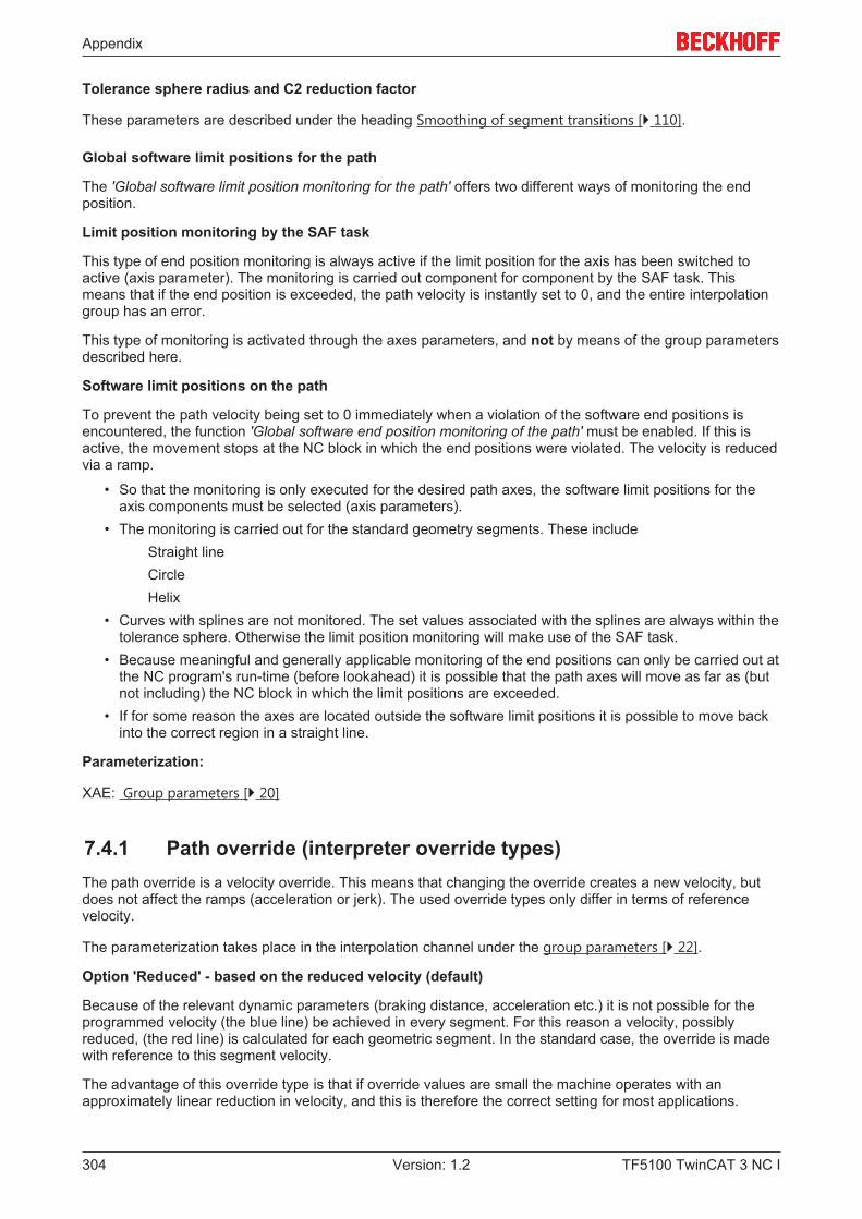
Appendix
TF5100 TwinCAT 3 NC I304 Version: 1.2
Tolerance sphere radius and C2 reduction factor
These parameters are described under the heading Smoothing of segment transitions [} 110].
Global software limit positions for the path
The 'Global software limit position monitoring for the path' offers two different ways of monitoring the endposition.
Limit position monitoring by the SAF task
This type of end position monitoring is always active if the limit position for the axis has been switched toactive (axis parameter). The monitoring is carried out component for component by the SAF task. Thismeans that if the end position is exceeded, the path velocity is instantly set to 0, and the entire interpolationgroup has an error.
This type of monitoring is activated through the axes parameters, and not by means of the group parametersdescribed here.
Software limit positions on the path
To prevent the path velocity being set to 0 immediately when a violation of the software end positions isencountered, the function 'Global software end position monitoring of the path' must be enabled. If this isactive, the movement stops at the NC block in which the end positions were violated. The velocity is reducedvia a ramp.
• So that the monitoring is only executed for the desired path axes, the software limit positions for theaxis components must be selected (axis parameters).
• The monitoring is carried out for the standard geometry segments. These includeStraight lineCircleHelix
• Curves with splines are not monitored. The set values associated with the splines are always within thetolerance sphere. Otherwise the limit position monitoring will make use of the SAF task.
• Because meaningful and generally applicable monitoring of the end positions can only be carried out atthe NC program's run-time (before lookahead) it is possible that the path axes will move as far as (butnot including) the NC block in which the limit positions are exceeded.
• If for some reason the axes are located outside the software limit positions it is possible to move backinto the correct region in a straight line.
Parameterization:
XAE: Group parameters [} 20]
7.4.1 Path override (interpreter override types)The path override is a velocity override. This means that changing the override creates a new velocity, butdoes not affect the ramps (acceleration or jerk). The used override types only differ in terms of referencevelocity.
The parameterization takes place in the interpolation channel under the group parameters [} 22].
Option 'Reduced' - based on the reduced velocity (default)
Because of the relevant dynamic parameters (braking distance, acceleration etc.) it is not possible for theprogrammed velocity (the blue line) be achieved in every segment. For this reason a velocity, possiblyreduced, (the red line) is calculated for each geometric segment. In the standard case, the override is madewith reference to this segment velocity.
The advantage of this override type is that if override values are small the machine operates with anapproximately linear reduction in velocity, and this is therefore the correct setting for most applications.
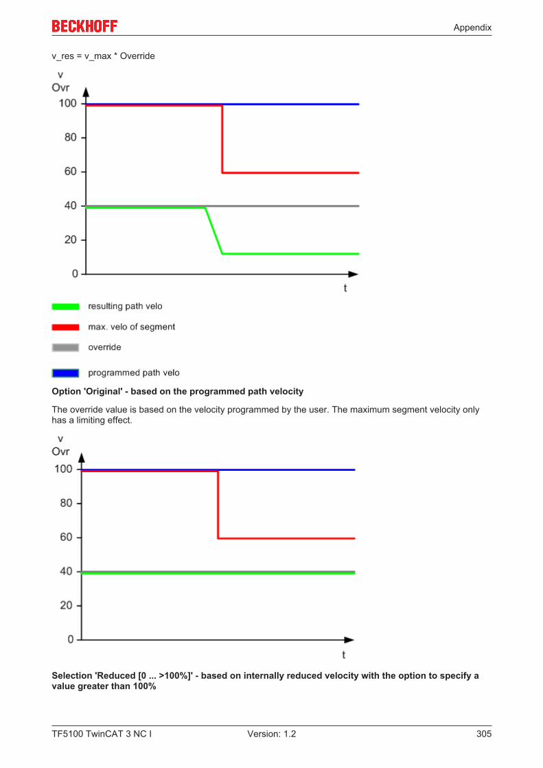
Appendix
TF5100 TwinCAT 3 NC I 305Version: 1.2
v_res = v_max * Override
Option 'Original' - based on the programmed path velocity
The override value is based on the velocity programmed by the user. The maximum segment velocity onlyhas a limiting effect.
Selection 'Reduced [0 ... >100%]' - based on internally reduced velocity with the option to specify avalue greater than 100%
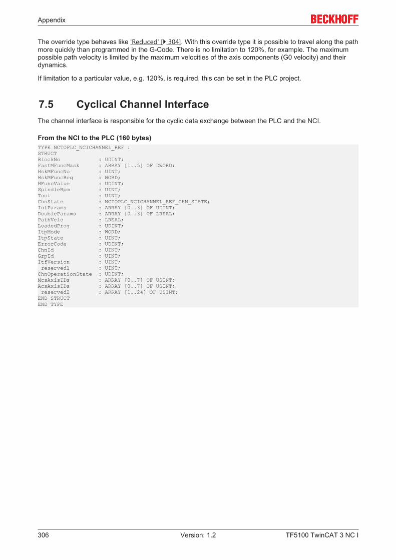
Appendix
TF5100 TwinCAT 3 NC I306 Version: 1.2
The override type behaves like 'Reduced' [} 304]. With this override type it is possible to travel along the pathmore quickly than programmed in the G-Code. There is no limitation to 120%, for example. The maximumpossible path velocity is limited by the maximum velocities of the axis components (G0 velocity) and theirdynamics.
If limitation to a particular value, e.g. 120%, is required, this can be set in the PLC project.
7.5 Cyclical Channel InterfaceThe channel interface is responsible for the cyclic data exchange between the PLC and the NCI.
From the NCI to the PLC (160 bytes)TYPE NCTOPLC_NCICHANNEL_REF : STRUCTBlockNo : UDINT;FastMFuncMask : ARRAY [1..5] OF DWORD;HskMFuncNo : UINT;HskMFuncReq : WORD;HFuncValue : UDINT;SpindleRpm : UINT;Tool : UINT;ChnState : NCTOPLC_NCICHANNEL_REF_CHN_STATE;IntParams : ARRAY [0..3] OF UDINT;DoubleParams : ARRAY [0..3] OF LREAL;PathVelo : LREAL;LoadedProg : UDINT;ItpMode : WORD;ItpState : UINT;ErrorCode : UDINT;ChnId : UINT;GrpId : UINT;ItfVersion : UINT;_reserved1 : UINT;ChnOperationState : UDINT;McsAxisIDs : ARRAY [0..7] OF USINT;AcsAxisIDs : ARRAY [0..7] OF USINT;_reserved2 : ARRAY [1..24] OF USINT;END_STRUCTEND_TYPE
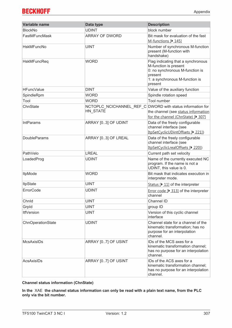
Appendix
TF5100 TwinCAT 3 NC I 307Version: 1.2
Variable name Data type DescriptionBlockNo UDINT block numberFastMFuncMask ARRAY OF DWORD Bit mask for evaluation of the fast
M-functions [} 145]HskMFuncNo UINT Number of synchronous M-function
present (M-function withhandshake)
HskMFuncReq WORD Flag indicating that a synchronousM-function is present0: no synchronous M-function ispresent1: a synchronous M-function ispresent
HFuncValue DINT Value of the auxiliary functionSpindleRpm WORD Spindle rotation speedTool WORD Tool numberChnState NCTOPLC_NCICHANNEL_REF_C
HN_STATEDWORD with status information forthe channel (see status informationfor the channel (ChnState) [} 307]
IntParams ARRAY [0..3] OF UDINT Data of the freely configurablechannel interface (seeItpSetCyclicUDintOffsets [} 221])
DoubleParams ARRAY [0..3] OF LREAL Data of the freely configurablechannel interface (seeItpSetCyclicLrealOffsets [} 220])
PathVelo LREAL Current path set velocityLoadedProg UDINT Name of the currently executed NC
program. If the name is not aUDINT, this value is 0.
ItpMode WORD Bit mask that indicates execution ininterpreter mode.
ItpState UINT Status [} 11] of the interpreterErrorCode UDINT Error code [} 313] of the interpreter
channelChnId UINT Channel IDGrpId UINT group IDItfVersion UINT Version of this cyclic channel
interfaceChnOperationState UDINT Channel state for a channel of the
kinematic transformation; has nopurpose for an interpolationchannel.
McsAxisIDs ARRAY [0..7] OF USINT IDs of the MCS axes for akinematic transformation channel;has no purpose for an interpolationchannel.
AcsAxisIDs ARRAY [0..7] OF USINT IDs of the ACS axes for akinematic transformation channel;has no purpose for an interpolationchannel.
Channel status information (ChnState)
In the XAE the channel status information can only be read with a plain text name, from the PLConly via the bit number.

Appendix
TF5100 TwinCAT 3 NC I308 Version: 1.2
Name Bit number (zero based) DescriptionbIsInterpolationChannel 0 Indicates that the linked channel is
an interpolation channel.bIsKinematicChannel 1 Indicates that the structure is linked
to a channel for the kinematictransformation.
bIsEStopRequested 8 Indicates that an ItpEStop wascalled, without checking whetherthe axes are already at standstill.
bIsFeedFromBackupList 10 For retracing the current entriesfrom the interpreter backup list aresent.
bIsMovingBackward 11 Indicates that the current motion isa reversing motion.
bRetraceStartPosReached 12 Indicates that the program startwas reached during reversing.
From PLC to NCI (128 bytes)TYPE PLCTONC_NCICHANNEL_REF :STRUCTSkipLine : WORD; (* Mask to skip lines *)ItpMode : WORD;MFuncGranted : WORD; (* granted signal of the M-function *)_reserved1 : UINT;ChnAxesOvr : UDINT; (* Channel override in percent * 100 *)ChnSpindleOvr : UDINT;_reserved2 : ARRAY [1..112] OF USINT;END_STRUCTEND_TYPE
Variable name Data type DescriptionSkipLine WORD Bit mask with which block skipping
[} 108] of the NCI is parameterizedfrom the PLC
ItpMode WORD Bit mask with which the interpreterexecution mode can be altered.This is, for instance, required if theinterpreter is to operate in singleblock [} 114] mode.
MFuncGranted WORD Flag with which an M-function oftype 'Handshake' is confirmed.0: Not acknowledged1: Acknowledgement
ChnAxesOvr UDINT Channel override for the axes from0...1000000 (corresponds to 0 -100%)
ChnSpindleOvr UDINT Channel override for the spindlebetween 0 and 1000000(corresponds to 0 - 100%);currently not supported.
7.6 ADS Return CodesError codes: 0x000 [} 309]..., 0x500 [} 309]..., 0x700 [} 310]..., 0x1000 [} 312]...
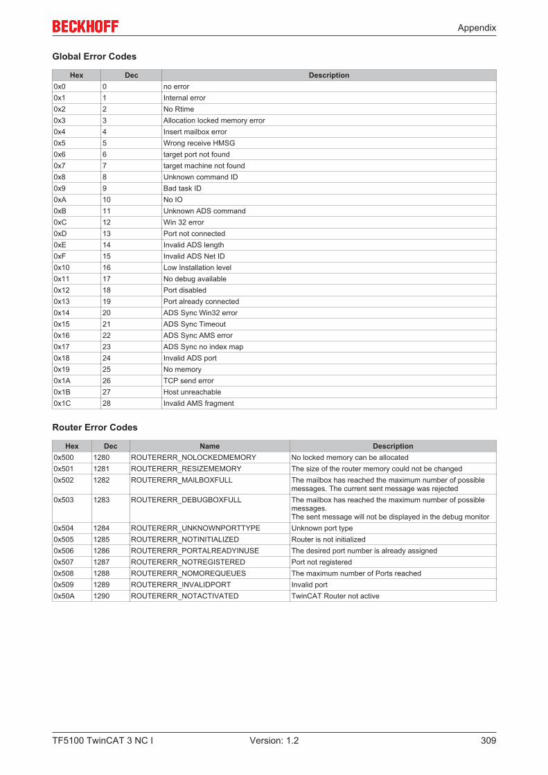
Appendix
TF5100 TwinCAT 3 NC I 309Version: 1.2
Global Error Codes
Hex Dec Description0x0 0 no error0x1 1 Internal error0x2 2 No Rtime0x3 3 Allocation locked memory error0x4 4 Insert mailbox error0x5 5 Wrong receive HMSG0x6 6 target port not found0x7 7 target machine not found0x8 8 Unknown command ID0x9 9 Bad task ID0xA 10 No IO0xB 11 Unknown ADS command0xC 12 Win 32 error0xD 13 Port not connected0xE 14 Invalid ADS length0xF 15 Invalid ADS Net ID0x10 16 Low Installation level0x11 17 No debug available0x12 18 Port disabled0x13 19 Port already connected0x14 20 ADS Sync Win32 error0x15 21 ADS Sync Timeout0x16 22 ADS Sync AMS error0x17 23 ADS Sync no index map0x18 24 Invalid ADS port0x19 25 No memory0x1A 26 TCP send error0x1B 27 Host unreachable0x1C 28 Invalid AMS fragment
Router Error Codes
Hex Dec Name Description0x500 1280 ROUTERERR_NOLOCKEDMEMORY No locked memory can be allocated0x501 1281 ROUTERERR_RESIZEMEMORY The size of the router memory could not be changed0x502 1282 ROUTERERR_MAILBOXFULL The mailbox has reached the maximum number of possible
messages. The current sent message was rejected0x503 1283 ROUTERERR_DEBUGBOXFULL The mailbox has reached the maximum number of possible
messages.The sent message will not be displayed in the debug monitor
0x504 1284 ROUTERERR_UNKNOWNPORTTYPE Unknown port type0x505 1285 ROUTERERR_NOTINITIALIZED Router is not initialized0x506 1286 ROUTERERR_PORTALREADYINUSE The desired port number is already assigned0x507 1287 ROUTERERR_NOTREGISTERED Port not registered0x508 1288 ROUTERERR_NOMOREQUEUES The maximum number of Ports reached0x509 1289 ROUTERERR_INVALIDPORT Invalid port0x50A 1290 ROUTERERR_NOTACTIVATED TwinCAT Router not active
Appendix
TF5100 TwinCAT 3 NC I310 Version: 1.2
General ADS Error Codes

Appendix
TF5100 TwinCAT 3 NC I 311Version: 1.2
Hex Dec Name Description0x700 1792 ADSERR_DEVICE_ERROR error class <device error>0x701 1793 ADSERR_DEVICE_SRVNOTSUPP Service is not supported by server0x702 1794 ADSERR_DEVICE_INVALIDGRP invalid index group0x703 1795 ADSERR_DEVICE_INVALIDOFFSET invalid index offset0x704 1796 ADSERR_DEVICE_INVALIDACCESS reading/writing not permitted0x705 1797 ADSERR_DEVICE_INVALIDSIZE parameter size not correct0x706 1798 ADSERR_DEVICE_INVALIDDATA invalid parameter value(s)0x707 1799 ADSERR_DEVICE_NOTREADY device is not in a ready state0x708 1800 ADSERR_DEVICE_BUSY device is busy0x709 1801 ADSERR_DEVICE_INVALIDCONTEXT invalid context (must be in Windows)0x70A 1802 ADSERR_DEVICE_NOMEMORY out of memory0x70B 1803 ADSERR_DEVICE_INVALIDPARM invalid parameter value(s)0x70C 1804 ADSERR_DEVICE_NOTFOUND not found (files, ...)0x70D 1805 ADSERR_DEVICE_SYNTAX syntax error in command or file0x70E 1806 ADSERR_DEVICE_INCOMPATIBLE objects do not match0x70F 1807 ADSERR_DEVICE_EXISTS object already exists0x710 1808 ADSERR_DEVICE_SYMBOLNOTFOUND symbol not found0x711 1809 ADSERR_DEVICE_SYMBOLVERSIONINVAL symbol version invalid
0x712 1810 ADSERR_DEVICE_INVALIDSTATE server is in invalid state0x713 1811 ADSERR_DEVICE_TRANSMODENOTSUPP AdsTransMode not supported0x714 1812 ADSERR_DEVICE_NOTIFYHNDINVALID Notification handle is invalid
0x715 1813 ADSERR_DEVICE_CLIENTUNKNOWN Notification client not registered0x716 1814 ADSERR_DEVICE_NOMOREHDLS no more notification handles0x717 1815 ADSERR_DEVICE_INVALIDWATCHSIZE size for watch too big0x718 1816 ADSERR_DEVICE_NOTINIT device not initialized0x719 1817 ADSERR_DEVICE_TIMEOUT device has a timeout0x71A 1818 ADSERR_DEVICE_NOINTERFACE query interface failed0x71B 1819 ADSERR_DEVICE_INVALIDINTERFACE wrong interface required0x71C 1820 ADSERR_DEVICE_INVALIDCLSID class ID is invalid0x71D 1821 ADSERR_DEVICE_INVALIDOBJID object ID is invalid0x71E 1822 ADSERR_DEVICE_PENDING request is pending0x71F 1823 ADSERR_DEVICE_ABORTED request is aborted0x720 1824 ADSERR_DEVICE_WARNING signal warning0x721 1825 ADSERR_DEVICE_INVALIDARRAYIDX invalid array index0x722 1826 ADSERR_DEVICE_SYMBOLNOTACTIVE symbol not active0x723 1827 ADSERR_DEVICE_ACCESSDENIED access denied0x724 1828 ADSERR_DEVICE_LICENSENOTFOUND missing license0x725 1829 ADSERR_DEVICE_LICENSEEXPIRED license expired0x726 1830 ADSERR_DEVICE_LICENSEEXCEEDED license exceeded0x727 1831 ADSERR_DEVICE_LICENSEINVALID license invalid0x728 1832 ADSERR_DEVICE_LICENSESYSTEMID license invalid system id0x729 1833 ADSERR_DEVICE_LICENSENOTIMELIMIT license not time limited0x72A 1834 ADSERR_DEVICE_LICENSEFUTUREISSUE license issue time in the future0x72B 1835 ADSERR_DEVICE_LICENSETIMETOLONG license time period to long0x72c 1836 ADSERR_DEVICE_EXCEPTION exception occured during system start0x72D 1837 ADSERR_DEVICE_LICENSEDUPLICATED License file read twice0x72E 1838 ADSERR_DEVICE_SIGNATUREINVALID invalid signature0x72F 1839 ADSERR_DEVICE_CERTIFICATEINVALID public key certificate0x740 1856 ADSERR_CLIENT_ERROR Error class <client error>0x741 1857 ADSERR_CLIENT_INVALIDPARM invalid parameter at service0x742 1858 ADSERR_CLIENT_LISTEMPTY polling list is empty0x743 1859 ADSERR_CLIENT_VARUSED var connection already in use0x744 1860 ADSERR_CLIENT_DUPLINVOKEID invoke ID in use0x745 1861 ADSERR_CLIENT_SYNCTIMEOUT timeout elapsed0x746 1862 ADSERR_CLIENT_W32ERROR error in win32 subsystem0x747 1863 ADSERR_CLIENT_TIMEOUTINVALID Invalid client timeout value
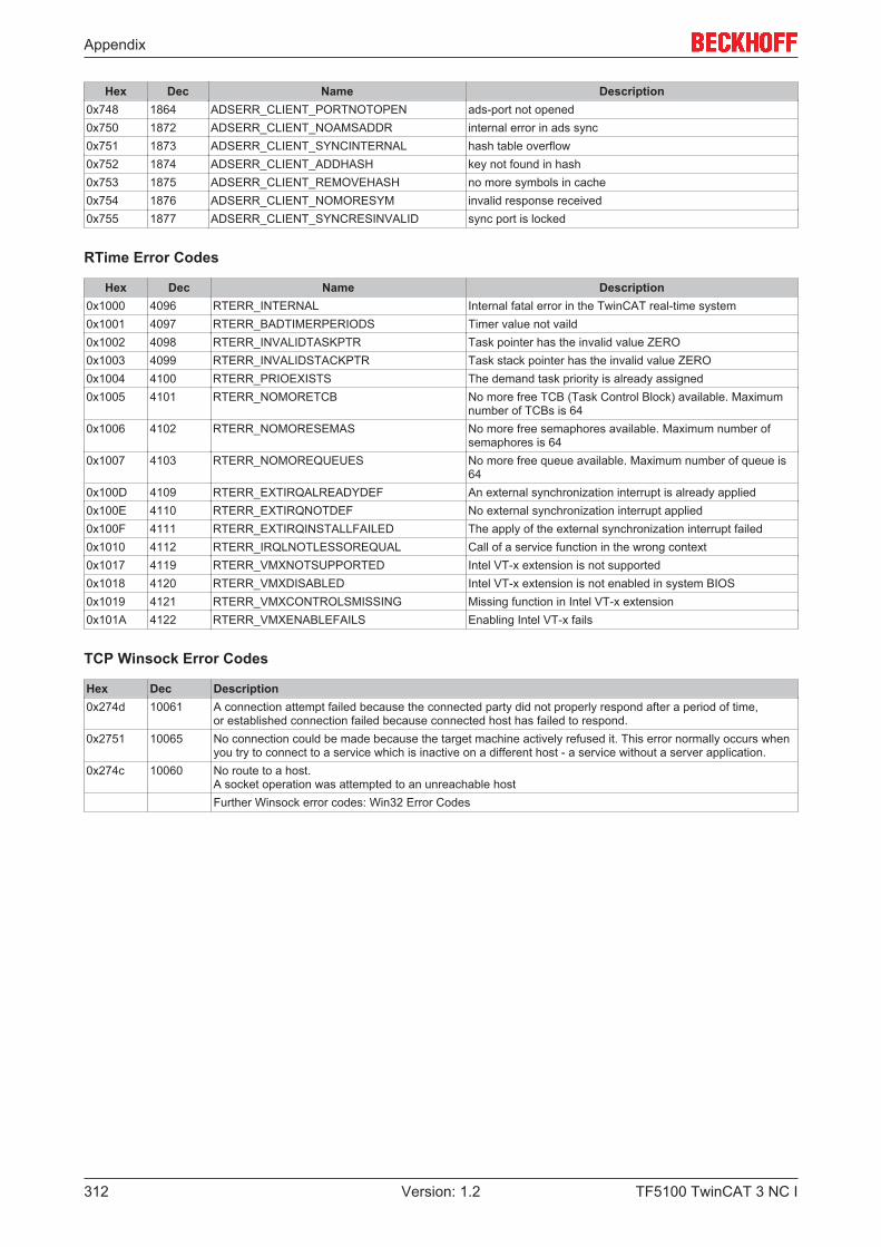
Appendix
TF5100 TwinCAT 3 NC I312 Version: 1.2
Hex Dec Name Description0x748 1864 ADSERR_CLIENT_PORTNOTOPEN ads-port not opened0x750 1872 ADSERR_CLIENT_NOAMSADDR internal error in ads sync0x751 1873 ADSERR_CLIENT_SYNCINTERNAL hash table overflow0x752 1874 ADSERR_CLIENT_ADDHASH key not found in hash0x753 1875 ADSERR_CLIENT_REMOVEHASH no more symbols in cache0x754 1876 ADSERR_CLIENT_NOMORESYM invalid response received0x755 1877 ADSERR_CLIENT_SYNCRESINVALID sync port is locked
RTime Error Codes
Hex Dec Name Description0x1000 4096 RTERR_INTERNAL Internal fatal error in the TwinCAT real-time system0x1001 4097 RTERR_BADTIMERPERIODS Timer value not vaild0x1002 4098 RTERR_INVALIDTASKPTR Task pointer has the invalid value ZERO0x1003 4099 RTERR_INVALIDSTACKPTR Task stack pointer has the invalid value ZERO0x1004 4100 RTERR_PRIOEXISTS The demand task priority is already assigned0x1005 4101 RTERR_NOMORETCB No more free TCB (Task Control Block) available. Maximum
number of TCBs is 640x1006 4102 RTERR_NOMORESEMAS No more free semaphores available. Maximum number of
semaphores is 640x1007 4103 RTERR_NOMOREQUEUES No more free queue available. Maximum number of queue is
640x100D 4109 RTERR_EXTIRQALREADYDEF An external synchronization interrupt is already applied0x100E 4110 RTERR_EXTIRQNOTDEF No external synchronization interrupt applied0x100F 4111 RTERR_EXTIRQINSTALLFAILED The apply of the external synchronization interrupt failed0x1010 4112 RTERR_IRQLNOTLESSOREQUAL Call of a service function in the wrong context0x1017 4119 RTERR_VMXNOTSUPPORTED Intel VT-x extension is not supported0x1018 4120 RTERR_VMXDISABLED Intel VT-x extension is not enabled in system BIOS0x1019 4121 RTERR_VMXCONTROLSMISSING Missing function in Intel VT-x extension0x101A 4122 RTERR_VMXENABLEFAILS Enabling Intel VT-x fails
TCP Winsock Error Codes
Hex Dec Description0x274d 10061 A connection attempt failed because the connected party did not properly respond after a period of time,
or established connection failed because connected host has failed to respond.0x2751 10065 No connection could be made because the target machine actively refused it. This error normally occurs when
you try to connect to a service which is inactive on a different host - a service without a server application.0x274c 10060 No route to a host.
A socket operation was attempted to an unreachable hostFurther Winsock error codes: Win32 Error Codes
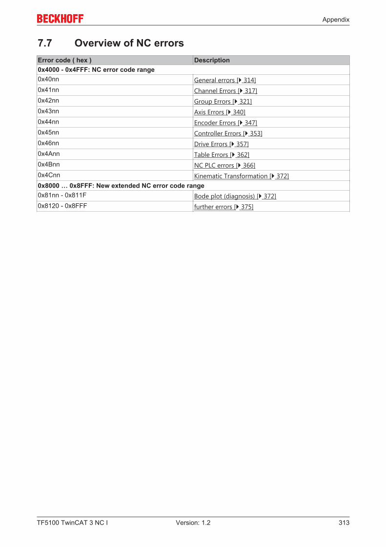
Appendix
TF5100 TwinCAT 3 NC I 313Version: 1.2
7.7 Overview of NC errorsError code ( hex ) Description0x4000 - 0x4FFF: NC error code range0x40nn General errors [} 314]0x41nn Channel Errors [} 317]0x42nn Group Errors [} 321]0x43nn Axis Errors [} 340]0x44nn Encoder Errors [} 347]0x45nn Controller Errors [} 353]0x46nn Drive Errors [} 357]0x4Ann Table Errors [} 362]0x4Bnn NC PLC errors [} 366]0x4Cnn Kinematic Transformation [} 372]0x8000 … 0x8FFF: New extended NC error code range0x81nn - 0x811F Bode plot (diagnosis) [} 372]0x8120 - 0x8FFF further errors [} 375]
Appendix
TF5100 TwinCAT 3 NC I314 Version: 1.2
7.7.1 General NC Errors
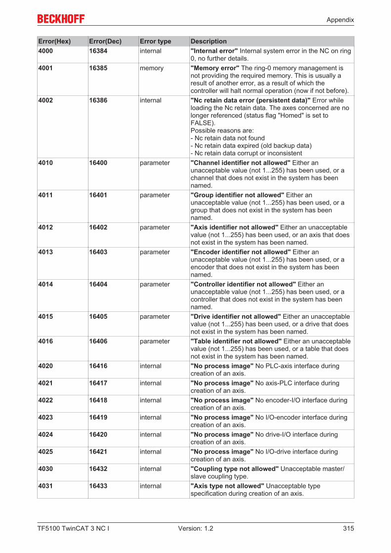
Appendix
TF5100 TwinCAT 3 NC I 315Version: 1.2
Error(Hex) Error(Dec) Error type Description4000 16384 internal "Internal error" Internal system error in the NC on ring
0, no further details.4001 16385 memory "Memory error" The ring-0 memory management is
not providing the required memory. This is usually aresult of another error, as a result of which thecontroller will halt normal operation (now if not before).
4002 16386 internal "Nc retain data error (persistent data)" Error whileloading the Nc retain data. The axes concerned are nolonger referenced (status flag "Homed" is set toFALSE).Possible reasons are:- Nc retain data not found- Nc retain data expired (old backup data)- Nc retain data corrupt or inconsistent
4010 16400 parameter "Channel identifier not allowed" Either anunacceptable value (not 1...255) has been used, or achannel that does not exist in the system has beennamed.
4011 16401 parameter "Group identifier not allowed" Either anunacceptable value (not 1...255) has been used, or agroup that does not exist in the system has beennamed.
4012 16402 parameter "Axis identifier not allowed" Either an unacceptablevalue (not 1...255) has been used, or an axis that doesnot exist in the system has been named.
4013 16403 parameter "Encoder identifier not allowed" Either anunacceptable value (not 1...255) has been used, or aencoder that does not exist in the system has beennamed.
4014 16404 parameter "Controller identifier not allowed" Either anunacceptable value (not 1...255) has been used, or acontroller that does not exist in the system has beennamed.
4015 16405 parameter "Drive identifier not allowed" Either an unacceptablevalue (not 1...255) has been used, or a drive that doesnot exist in the system has been named.
4016 16406 parameter "Table identifier not allowed" Either an unacceptablevalue (not 1...255) has been used, or a table that doesnot exist in the system has been named.
4020 16416 internal "No process image" No PLC-axis interface duringcreation of an axis.
4021 16417 internal "No process image" No axis-PLC interface duringcreation of an axis.
4022 16418 internal "No process image" No encoder-I/O interface duringcreation of an axis.
4023 16419 internal "No process image" No I/O-encoder interface duringcreation of an axis.
4024 16420 internal "No process image" No drive-I/O interface duringcreation of an axis.
4025 16421 internal "No process image" No I/O-drive interface duringcreation of an axis.
4030 16432 internal "Coupling type not allowed" Unacceptable master/slave coupling type.
4031 16433 internal "Axis type not allowed" Unacceptable typespecification during creation of an axis.
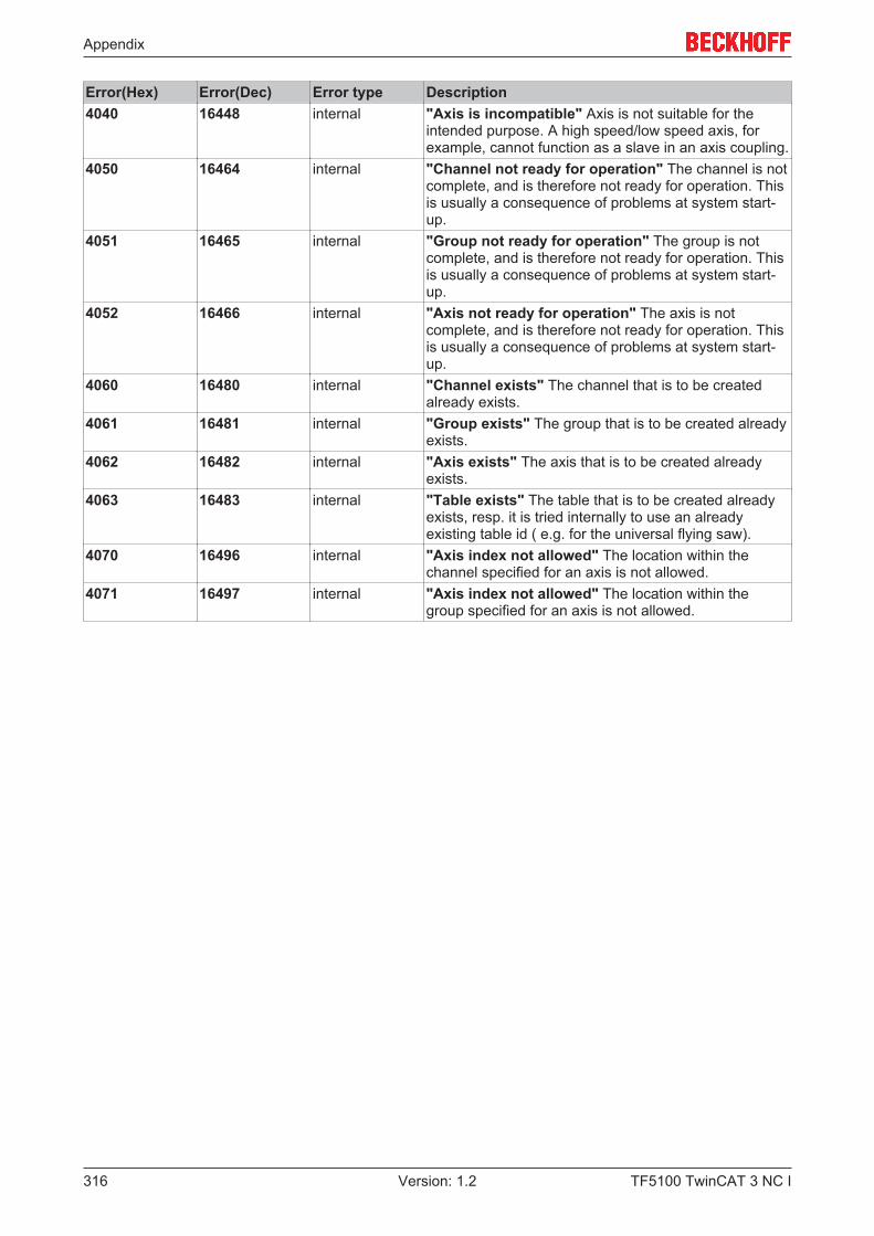
Appendix
TF5100 TwinCAT 3 NC I316 Version: 1.2
Error(Hex) Error(Dec) Error type Description4040 16448 internal "Axis is incompatible" Axis is not suitable for the
intended purpose. A high speed/low speed axis, forexample, cannot function as a slave in an axis coupling.
4050 16464 internal "Channel not ready for operation" The channel is notcomplete, and is therefore not ready for operation. Thisis usually a consequence of problems at system start-up.
4051 16465 internal "Group not ready for operation" The group is notcomplete, and is therefore not ready for operation. Thisis usually a consequence of problems at system start-up.
4052 16466 internal "Axis not ready for operation" The axis is notcomplete, and is therefore not ready for operation. Thisis usually a consequence of problems at system start-up.
4060 16480 internal "Channel exists" The channel that is to be createdalready exists.
4061 16481 internal "Group exists" The group that is to be created alreadyexists.
4062 16482 internal "Axis exists" The axis that is to be created alreadyexists.
4063 16483 internal "Table exists" The table that is to be created alreadyexists, resp. it is tried internally to use an alreadyexisting table id ( e.g. for the universal flying saw).
4070 16496 internal "Axis index not allowed" The location within thechannel specified for an axis is not allowed.
4071 16497 internal "Axis index not allowed" The location within thegroup specified for an axis is not allowed.

Appendix
TF5100 TwinCAT 3 NC I 317Version: 1.2
7.7.2 Channel Errors

Appendix
TF5100 TwinCAT 3 NC I318 Version: 1.2
Error(Hex) Error(Dec) Error type Description4101 16641 Parameter "Group index not allowed" The location within the
channel specified for a group is not allowed.4102 16642 Address "Null pointer" The pointer to the group is invalid.
This is usually a consequence of an error at systemstart-up.
4103 16643 Internal "No process image" It is not possible to exchangedata with the PLC. Possible causes: n the channeldoes not have an interface (no interpreter present)n The connection to the PLC is faulty
4104 16644 Parameter "M-function index not allowed" Unacceptable M-function (not 0...159) detected at the executionlevel.
4105 16645 Memory "No memory" No more system memory isavailable. This is usually the result of another error.
4106 16646 Function "Not ready" The function is not presently available,because a similar function is already beingprocessed. This is usually the result of accessconflicts: more than one instance wants to issuecommands to the channel. This can, for example,be the consequence of an incorrect PLC program.
4107 16647 Function "Function/command not supported" A requestedfunction or command is not supported by thechannel.
4108 16648 Parameter "Invalid parameter while starting" Parameters tostart the channel (TwinCAT-Start) are invalid.Typically there is an invalid memory size or channeltype requested.
4109 16649 Function "Channel function/command not executable" Achannel function e.g. interpreter start is notexecutable because the channel is already busy, noprogram is loaded or in an error state.
410A 16650 Function "ItpGoAhead not executable" The requestedcommand is not executable, because theinterpreter is not executing a decoder stop.
4110 16656 Parameter "Error opening a file" The specified file does notexist. Sample: NC program unknown.
4111 16657 NCprogramming
"Syntax error during loading" The NC has founda syntax error when loading an NC program.
4112 16658 NCprogramming
"Syntax error during interpretation" The NC hasfound a syntax error when executing an NCprogram.
4113 16659 NCprogramming
"Missing subroutine" The NC has found amissing subroutine while loading.
4114 16660 Memory "Loading buffer of interpreter is too small" Thecapacity of the interpreter loading buffer has beenexceeded.
4115 16661 Internal “Symbolic” - reserved4116 16662 Internal “Symbolic” - reserved4117 16663 NC
programming"Subroutine incomplete" Header of subroutine ismissing
4118 16664 NCprogramming
"Error while loading the NC program" Themaximum number of loadable NC programs hasbeen reached.Possible cause:Too many sub-programs were loaded from a mainprogram.

Appendix
TF5100 TwinCAT 3 NC I 319Version: 1.2
Error(Hex) Error(Dec) Error type Description4119 16665 NC
programming"Error while loading the NC program" Theprogram name is too long.
4120 16672 NCprogramming
"Divide by zero" The NC encountered acomputation error during execution: division by 0.
4121 16673 NCprogramming
"Invalid circle parameterization" The NCencountered a computation error during execution:The specified circle cannot be calculated.
4122 16674 NCprogramming
"Invalid FPU-Operation" The NC encountered aninvalid FPU-Operation during execution. This erroroccurs e.g. by calculating the square root of anegative number.
4130 16688 NCprogramming
"Stack overflow: subroutines" The NCencountered a stack overflow during execution: toomany subroutine levels.
4131 16689 NCprogramming
"Stack underflow: subroutines" The NCencountered a stack underflow during execution:too many subroutine return commands. Note: Amain program must not end with a return command.
4132 16690 NCprogramming
"Stack overflow: arithmetic unit" The NCencountered a stack overflow during execution: Thecalculation is too complex, or has not been correctlywritten.
4133 16691 NCprogramming
"Stack underflow: arithmetic unit" The NCencountered a stack underflow during execution:The calculation is too complex, or has not beencorrectly written.
4140 16704 Parameter "Register index not allowed" The NCencountered an unacceptable register index duringexecution: Either the program contains anunacceptable value (not R0...R999) or a pointerregister contains an unacceptable value.
4141 16705 NCprogramming
"Unacceptable G-function index" The NC hasencountered an unacceptable G-function (not0...159) during execution.
4142 16706 NCprogramming
"Unacceptable M-function index" The NC hasencountered an unacceptable M-function (not0...159) during execution.
4143 16707 NCprogramming
"Unacceptable extended address" The NC hasencountered an unacceptable extended address(not 1...9) during execution.
4144 16708 NCprogramming
"Unacceptable index to the internal H-function"The NC has encountered an unacceptable internalH-function in the course of processing. This isusually a consequence of an error during loading.
4145 16709 Parameter "Machine data value unacceptable" Whileprocessing instructions the NC has detected animpermissible value for the machine data (MDB)(not 0…7).
4150 16720 Parameter "Cannot change tool params here" The NC hasencountered an unacceptable change ofparameters for the tool compensation duringexecution. This error occurred for instance bychanging the tool radius and programming a circlein the same block.
4151 16721 Parameter "Cannot calculate tool compensation" The NChas encountered an error by the calculation of thetool compensation.
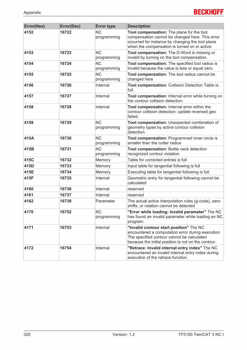
Appendix
TF5100 TwinCAT 3 NC I320 Version: 1.2
Error(Hex) Error(Dec) Error type Description4152 16722 NC
programmingTool compensation: The plane for the toolcompensation cannot be changed here. This erroroccurred for instance by changing the tool planewhen the compensation is turned on or active.
4153 16723 NCprogramming
Tool compensation: The D-Word is missing orinvalid by turning on the tool compensation.
4154 16724 NCprogramming
Tool compensation: The specified tool radius isinvalid because the value is less or equal zero.
4155 16725 NCprogramming
Tool compensation: The tool radius cannot bechanged here
4156 16726 Internal Tool compensation: Collision Detection Table isfull.
4157 16727 Internal Tool compensation: Internal error while turning onthe contour collision detection.
4158 16728 Internal Tool compensation: Internal error within thecontour collision detection: update reversed geofailed.
4159 16729 NCprogramming
Tool compensation: Unexpected combination ofgeometry types by active contour collisiondetection.
415A 16730 NCprogramming
Tool compensation: Programmed inner circle issmaller than the cutter radius
415B 16731 NCprogramming
Tool compensation: Bottle neck detectionrecognized contour violation
415C 16732 Memory Table for corrected entries is full415D 16733 Memory Input table for tangential following is full415E 16734 Memory Executing table for tangential following is full415F 16735 Internal Geometric entry for tangential following cannot be
calculated4160 16736 Internal reserved4161 16737 Internal reserved4162 16738 Parameter The actual active interpolation rules (g-code), zero-
shifts, or rotation cannot be detected4170 16752 NC
programming"Error while loading: Invalid parameter" The NChas found an invalid parameter while loading an NCprogram.
4171 16753 Internal "Invalid contour start position" The NCencountered a computation error during execution:The specified contour cannot be calculatedbecause the initial position is not on the contour.
4172 16754 Internal "Retrace: Invalid internal entry index" The NCencountered an invalid internal entry index duringexecution of the retrace function.

Appendix
TF5100 TwinCAT 3 NC I 321Version: 1.2
7.7.3 Group Errors
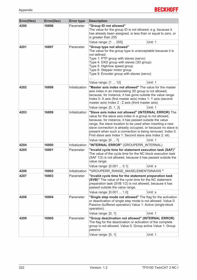
Appendix
TF5100 TwinCAT 3 NC I322 Version: 1.2
Error(Hex) Error(Dec) Error type Description4200 16896 Parameter "Group ID not allowed"
The value for the group ID is not allowed, e.g. because ithas already been assigned, is less than or equal to zero, oris greater than 255.Value range: [1 ... 255] Unit: 1
4201 16897 Parameter "Group type not allowed" The value for the group type is unacceptable because it isnot defined. Type 1: PTP group with slaves (servo) Type 4: DXD group with slaves (3D group) Type 5: High/low speed group Type 6: Stepper motor group Type 9: Encoder group with slaves (servo)…Value range: [1 ... 12] Unit: 1
4202 16898 Initialization "Master axis index not allowed" The value for the masteraxis index in an interpolating 3D group is not allowed,because, for instance, it has gone outside the value range.Index 0: X axis (first master axis) Index 1: Y axis (secondmaster axis) Index 2 : Z axis (third master axis)Value range: [0, 1, 2] Unit: 1
4203 16899 Initialization "Slave axis index not allowed" (INTERNAL ERROR) Thevalue for the slave axis index in a group is not allowed,because, for instance, it has passed outside the valuerange, the slave location to be used when inserting a newslave connection is already occupied, or because no slave ispresent when such a connection is being removed. Index 0:First slave axis Index 1: Second slave axis Index 2: etc.Value range: [0 ... 7] Unit: 1
4204 16900 Initialization "INTERNAL ERROR" (GROUPERR_INTERNAL)4205 16901 Parameter "Invalid cycle time for statement execution task (SAF)"
The value of the cycle time for the NC block execution task(SAF 1/2) is not allowed, because it has passed outside thevalue range.Value range: [0.001 ... 0.1] Unit: s
4206 16902 Initialization "GROUPERR_RANGE_MAXELEMENTSINAXIS "4207 16903 Parameter "Invalid cycle time for the statement preparation task
(SVB)" The value of the cycle time for the NC statementpreparation task (SVB 1/2) is not allowed, because it haspassed outside the value range.Value range: [0.001 ... 1.0] Unit: s
4208 16904 Parameter "Single step mode not allowed" The flag for the activationor deactivation of single step mode is not allowed. Value 0:Passive (buffered operation) Value 1: Active (single-blockoperation)Value range: [0, 1] Unit: 1
4209 16905 Parameter "Group deactivation not allowed" (INTERNAL ERROR)The flag for the deactivation or activation of the completegroup is not allowed. Value 0: Group active Value 1: GrouppassiveValue range: [0, 1] Unit: 1
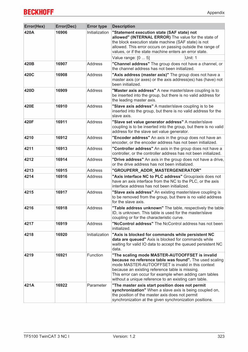
Appendix
TF5100 TwinCAT 3 NC I 323Version: 1.2
Error(Hex) Error(Dec) Error type Description420A 16906 Initialization "Statement execution state (SAF state) not
allowed" (INTERNAL ERROR) The value for the state ofthe block execution state machine (SAF state) is notallowed. This error occurs on passing outside the range ofvalues, or if the state machine enters an error state.Value range: [0 ... 5] Unit: 1
420B 16907 Address "Channel address" The group does not have a channel, orthe channel address has not been initialized.
420C 16908 Address "Axis address (master axis)" The group does not have amaster axis (or axes) or the axis address(es) has (have) notbeen initialized.
420D 16909 Address "Master axis address" A new master/slave coupling is tobe inserted into the group, but there is no valid address forthe leading master axis.
420E 16910 Address "Slave axis address" A master/slave coupling is to beinserted into the group, but there is no valid address for theslave axis.
420F 16911 Address "Slave set value generator address" A master/slavecoupling is to be inserted into the group, but there is no validaddress for the slave set value generator.
4210 16912 Address "Encoder address" An axis in the group does not have anencoder, or the encoder address has not been initialized.
4211 16913 Address "Controller address" An axis in the group does not have acontroller, or the controller address has not been initialized.
4212 16914 Address "Drive address" An axis in the group does not have a drive,or the drive address has not been initialized.
4213 16915 Address "GROUPERR_ADDR_MASTERGENERATOR"4214 16916 Address "Axis interface NC to PLC address" Group/axis does not
have an axis interface from the NC to the PLC, or the axisinterface address has not been initialized.
4215 16917 Address "Slave axis address" An existing master/slave coupling isto be removed from the group, but there is no valid addressfor the slave axis.
4216 16918 Address "Table address unknown" The table, respectively the tableID, is unknown. This table is used for the master/slavecoupling or for the characteristic curve.
4217 16919 Address "NcControl address" The NcControl address has not beeninitialized.
4218 16920 Initialization "Axis is blocked for commands while persistent NCdata are queued" Axis is blocked for commands whilewaiting for valid IO data to accept the queued persistent NCdata.
4219 16921 Function "The scaling mode MASTER-AUTOOFFSET is invalidbecause no reference table was found". The used scalingmode MASTER-AUTOOFFSET is invalid in this contextbecause an existing reference table is missing.This error can occur for example when adding cam tableswithout a unique reference to an existing cam table.
421A 16922 Parameter "The master axis start position does not permitsynchronization" When a slave axis is being coupled on,the position of the master axis does not permitsynchronization at the given synchronization positions.
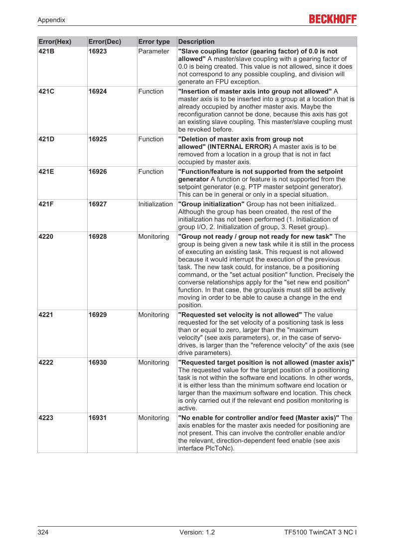
Appendix
TF5100 TwinCAT 3 NC I324 Version: 1.2
Error(Hex) Error(Dec) Error type Description421B 16923 Parameter "Slave coupling factor (gearing factor) of 0.0 is not
allowed" A master/slave coupling with a gearing factor of0.0 is being created. This value is not allowed, since it doesnot correspond to any possible coupling, and division willgenerate an FPU exception.
421C 16924 Function "Insertion of master axis into group not allowed" Amaster axis is to be inserted into a group at a location that isalready occupied by another master axis. Maybe thereconfiguration cannot be done, because this axis has gotan existing slave coupling. This master/slave coupling mustbe revoked before.
421D 16925 Function "Deletion of master axis from group notallowed" (INTERNAL ERROR) A master axis is to beremoved from a location in a group that is not in factoccupied by master axis.
421E 16926 Function "Function/feature is not supported from the setpointgenerator A function or feature is not supported from thesetpoint generator (e.g. PTP master setpoint generator).This can be in general or only in a special situation.
421F 16927 Initialization "Group initialization" Group has not been initialized.Although the group has been created, the rest of theinitialization has not been performed (1. Initialization ofgroup I/O, 2. Initialization of group, 3. Reset group).
4220 16928 Monitoring "Group not ready / group not ready for new task" Thegroup is being given a new task while it is still in the processof executing an existing task. This request is not allowedbecause it would interrupt the execution of the previoustask. The new task could, for instance, be a positioningcommand, or the "set actual position" function. Precisely theconverse relationships apply for the "set new end position"function. In that case, the group/axis must still be activelymoving in order to be able to cause a change in the endposition.
4221 16929 Monitoring "Requested set velocity is not allowed" The valuerequested for the set velocity of a positioning task is lessthan or equal to zero, larger than the "maximumvelocity" (see axis parameters), or, in the case of servo-drives, is larger than the "reference velocity" of the axis (seedrive parameters).
4222 16930 Monitoring "Requested target position is not allowed (master axis)"The requested value for the target position of a positioningtask is not within the software end locations. In other words,it is either less than the minimum software end location orlarger than the maximum software end location. This checkis only carried out if the relevant end position monitoring isactive.
4223 16931 Monitoring "No enable for controller and/or feed (Master axis)" Theaxis enables for the master axis needed for positioning arenot present. This can involve the controller enable and/orthe relevant, direction-dependent feed enable (see axisinterface PlcToNc).

Appendix
TF5100 TwinCAT 3 NC I 325Version: 1.2
Error(Hex) Error(Dec) Error type Description4224 16932 Monitoring "Movement smaller than one encoder
increment" (INTERNAL ERROR) The distance that agroup/axis is supposed to move is smaller than the physicalsignificance of one encoder increment. In other words themovement is smaller than the scaling factor of the axis. Thereaction to this is that the axis is reported as having logicallyfinished without having actively moved. This means that anexternal error is not generated for the user. This error is alsoissued for high/low speed axes if a loop movement withnonzero parameters is smaller than the sum of the creepingand braking distances. In such a case it is not meaningful toeither exceed or to fail to reach the target position.
4225 16933 Monitoring "Drive not ready during axis start" During an axis start itis ascertained that the drive is not ready. The following arepossible causes: - the drive is in the error state (hardwareerror) - the drive is in the start-up phase (e.g. after an axisreset that was preceded by a hardware error) - the drive ismissing the controller enable (ENABLE) Note: The timerequired for "booting" a drive after a hardware fault canamount to several seconds.
4226 16934 Monitoring "Invalid parameters of the emergency stop." Either, both,the deceleration and the jerk are less than zero or one of theparameters is weaker than the corresponding parameter ofthe start data.
4227 16935 Function "The setpoint generator is inactive such that noinstructions are accepted."
4228 16936 Monitoring "Requested traverse distance is not allowed" Therequested traverse distance or looping distance is smallerthan the braking distance of the two/speed axis.
4229 16937 Monitoring "Requested target position is not allowed (slave axis)"The value for the target position of a positioning task whencalculated for the slave axis is not within the software endlocations. In other words, it is either less than the minimumsoftware end location or larger than the maximum softwareend location. This check is only carried out if the relevantend position monitoring is active.
422A 16938 Monitoring "No enable for controller and/or feed (slave axis)" Theaxis enables for one or more coupled slave axes needed forpositioning are not present. This can involve the controllerenable and/or the relevant, direction-dependent feed enable(see axis interface PlcToNc).
422B 16939 Parameter "The activation position (position threshold) is out ofrange of the actual positioning" The activation position(position threshold) of a new axis command (e.g. "newvelocity activated at a position") is out of range. E.g. theactivation position is before the actual position or behind thetarget position.
422C 16940 Parameter "The start or activation data of the external setpointgeneration are not valid" This may be caused through: 1.The external setpoint generation is active and a newactivation with a start type (1: absolute, 2: relative) unequalto the current one is send.2. The internal setpoint generation is active (e.g. PTP) andthe external one is activated with the type absolute (twosetpoint generators of the type absolute are not possible).
422D 16941 Parameter "Velocity is not constant" For changing the dynamicparameter 'acceleration' und 'deceleration' the axis has to bein dynamic state without acceleration and deceleration (thatmeans constant velocity).
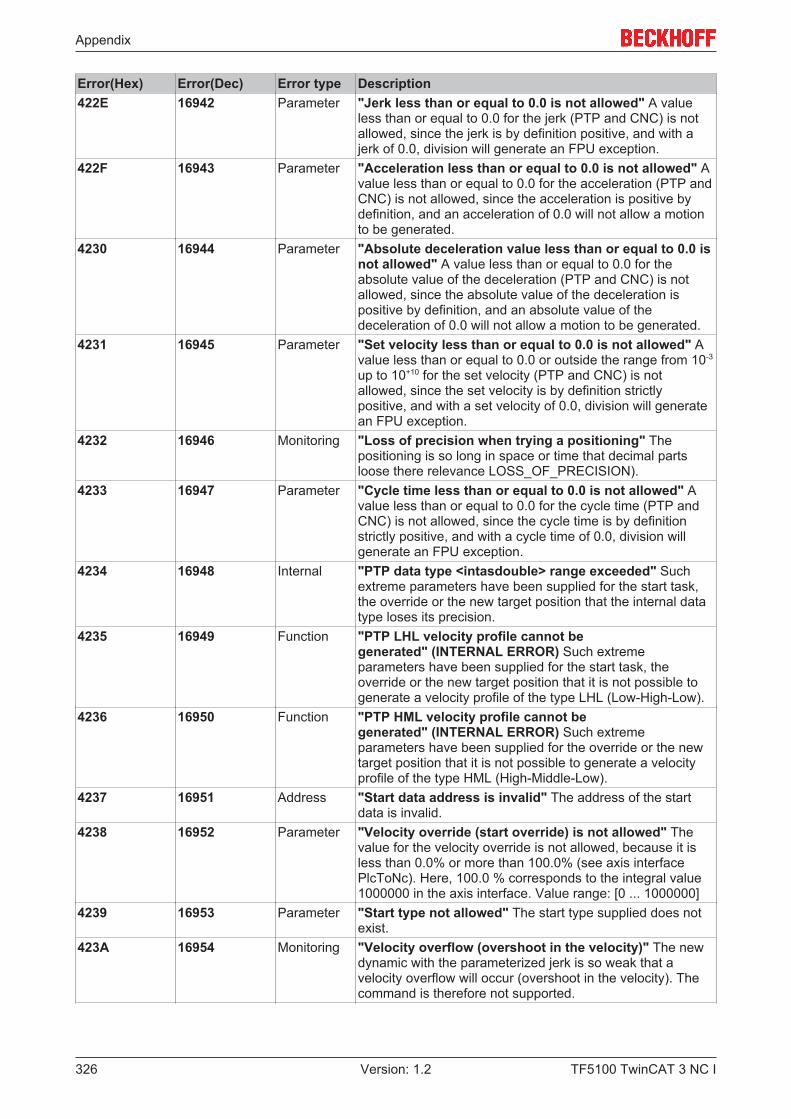
Appendix
TF5100 TwinCAT 3 NC I326 Version: 1.2
Error(Hex) Error(Dec) Error type Description422E 16942 Parameter "Jerk less than or equal to 0.0 is not allowed" A value
less than or equal to 0.0 for the jerk (PTP and CNC) is notallowed, since the jerk is by definition positive, and with ajerk of 0.0, division will generate an FPU exception.
422F 16943 Parameter "Acceleration less than or equal to 0.0 is not allowed" Avalue less than or equal to 0.0 for the acceleration (PTP andCNC) is not allowed, since the acceleration is positive bydefinition, and an acceleration of 0.0 will not allow a motionto be generated.
4230 16944 Parameter "Absolute deceleration value less than or equal to 0.0 isnot allowed" A value less than or equal to 0.0 for theabsolute value of the deceleration (PTP and CNC) is notallowed, since the absolute value of the deceleration ispositive by definition, and an absolute value of thedeceleration of 0.0 will not allow a motion to be generated.
4231 16945 Parameter "Set velocity less than or equal to 0.0 is not allowed" Avalue less than or equal to 0.0 or outside the range from 10-3
up to 10+10 for the set velocity (PTP and CNC) is notallowed, since the set velocity is by definition strictlypositive, and with a set velocity of 0.0, division will generatean FPU exception.
4232 16946 Monitoring "Loss of precision when trying a positioning" Thepositioning is so long in space or time that decimal partsloose there relevance LOSS_OF_PRECISION).
4233 16947 Parameter "Cycle time less than or equal to 0.0 is not allowed" Avalue less than or equal to 0.0 for the cycle time (PTP andCNC) is not allowed, since the cycle time is by definitionstrictly positive, and with a cycle time of 0.0, division willgenerate an FPU exception.
4234 16948 Internal "PTP data type <intasdouble> range exceeded" Suchextreme parameters have been supplied for the start task,the override or the new target position that the internal datatype loses its precision.
4235 16949 Function "PTP LHL velocity profile cannot begenerated" (INTERNAL ERROR) Such extremeparameters have been supplied for the start task, theoverride or the new target position that it is not possible togenerate a velocity profile of the type LHL (Low-High-Low).
4236 16950 Function "PTP HML velocity profile cannot begenerated" (INTERNAL ERROR) Such extremeparameters have been supplied for the override or the newtarget position that it is not possible to generate a velocityprofile of the type HML (High-Middle-Low).
4237 16951 Address "Start data address is invalid" The address of the startdata is invalid.
4238 16952 Parameter "Velocity override (start override) is not allowed" Thevalue for the velocity override is not allowed, because it isless than 0.0% or more than 100.0% (see axis interfacePlcToNc). Here, 100.0 % corresponds to the integral value1000000 in the axis interface. Value range: [0 ... 1000000]
4239 16953 Parameter "Start type not allowed" The start type supplied does notexist.
423A 16954 Monitoring "Velocity overflow (overshoot in the velocity)" The newdynamic with the parameterized jerk is so weak that avelocity overflow will occur (overshoot in the velocity). Thecommand is therefore not supported.
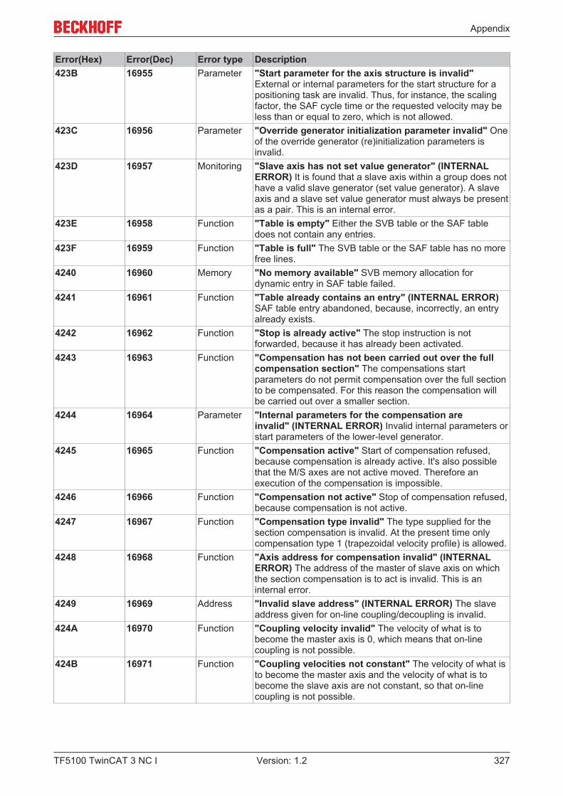
Appendix
TF5100 TwinCAT 3 NC I 327Version: 1.2
Error(Hex) Error(Dec) Error type Description423B 16955 Parameter "Start parameter for the axis structure is invalid"
External or internal parameters for the start structure for apositioning task are invalid. Thus, for instance, the scalingfactor, the SAF cycle time or the requested velocity may beless than or equal to zero, which is not allowed.
423C 16956 Parameter "Override generator initialization parameter invalid" Oneof the override generator (re)initialization parameters isinvalid.
423D 16957 Monitoring "Slave axis has not set value generator" (INTERNALERROR) It is found that a slave axis within a group does nothave a valid slave generator (set value generator). A slaveaxis and a slave set value generator must always be presentas a pair. This is an internal error.
423E 16958 Function "Table is empty" Either the SVB table or the SAF tabledoes not contain any entries.
423F 16959 Function "Table is full" The SVB table or the SAF table has no morefree lines.
4240 16960 Memory "No memory available" SVB memory allocation fordynamic entry in SAF table failed.
4241 16961 Function "Table already contains an entry" (INTERNAL ERROR)SAF table entry abandoned, because, incorrectly, an entryalready exists.
4242 16962 Function "Stop is already active" The stop instruction is notforwarded, because it has already been activated.
4243 16963 Function "Compensation has not been carried out over the fullcompensation section" The compensations startparameters do not permit compensation over the full sectionto be compensated. For this reason the compensation willbe carried out over a smaller section.
4244 16964 Parameter "Internal parameters for the compensation areinvalid" (INTERNAL ERROR) Invalid internal parameters orstart parameters of the lower-level generator.
4245 16965 Function "Compensation active" Start of compensation refused,because compensation is already active. It's also possiblethat the M/S axes are not active moved. Therefore anexecution of the compensation is impossible.
4246 16966 Function "Compensation not active" Stop of compensation refused,because compensation is not active.
4247 16967 Function "Compensation type invalid" The type supplied for thesection compensation is invalid. At the present time onlycompensation type 1 (trapezoidal velocity profile) is allowed.
4248 16968 Function "Axis address for compensation invalid" (INTERNALERROR) The address of the master of slave axis on whichthe section compensation is to act is invalid. This is aninternal error.
4249 16969 Address "Invalid slave address" (INTERNAL ERROR) The slaveaddress given for on-line coupling/decoupling is invalid.
424A 16970 Function "Coupling velocity invalid" The velocity of what is tobecome the master axis is 0, which means that on-linecoupling is not possible.
424B 16971 Function "Coupling velocities not constant" The velocity of what isto become the master axis and the velocity of what is tobecome the slave axis are not constant, so that on-linecoupling is not possible.
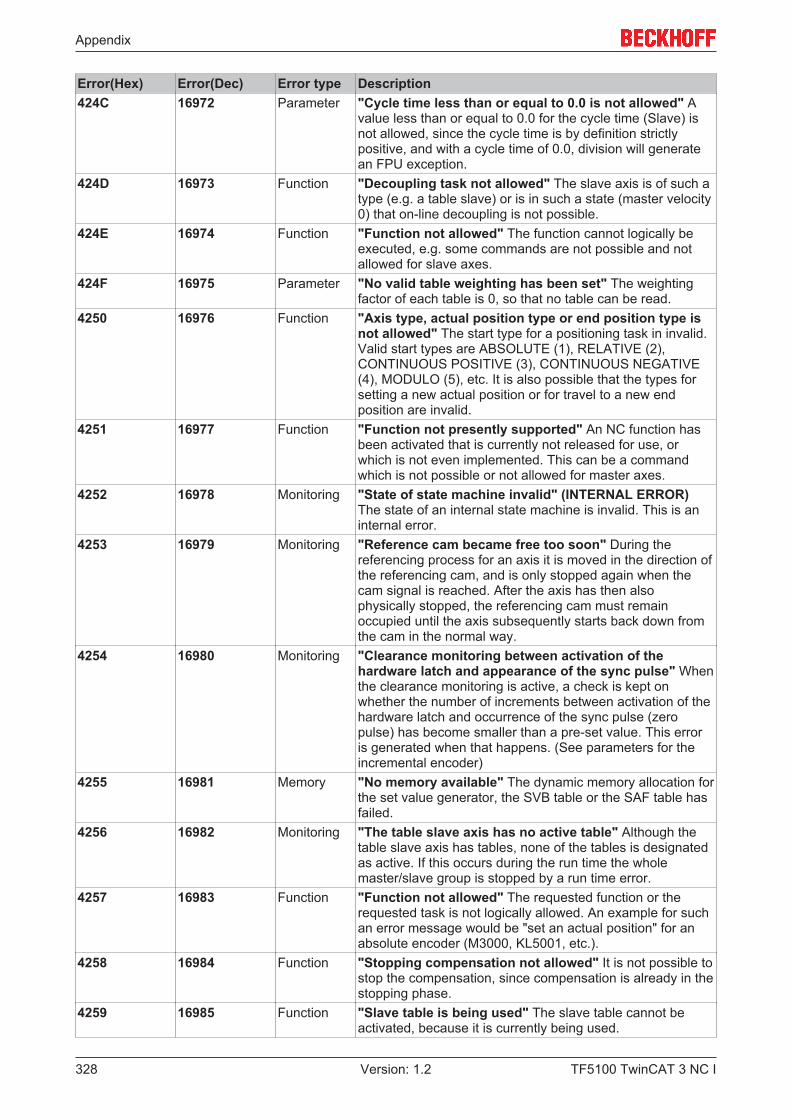
Appendix
TF5100 TwinCAT 3 NC I328 Version: 1.2
Error(Hex) Error(Dec) Error type Description424C 16972 Parameter "Cycle time less than or equal to 0.0 is not allowed" A
value less than or equal to 0.0 for the cycle time (Slave) isnot allowed, since the cycle time is by definition strictlypositive, and with a cycle time of 0.0, division will generatean FPU exception.
424D 16973 Function "Decoupling task not allowed" The slave axis is of such atype (e.g. a table slave) or is in such a state (master velocity0) that on-line decoupling is not possible.
424E 16974 Function "Function not allowed" The function cannot logically beexecuted, e.g. some commands are not possible and notallowed for slave axes.
424F 16975 Parameter "No valid table weighting has been set" The weightingfactor of each table is 0, so that no table can be read.
4250 16976 Function "Axis type, actual position type or end position type isnot allowed" The start type for a positioning task in invalid.Valid start types are ABSOLUTE (1), RELATIVE (2),CONTINUOUS POSITIVE (3), CONTINUOUS NEGATIVE(4), MODULO (5), etc. It is also possible that the types forsetting a new actual position or for travel to a new endposition are invalid.
4251 16977 Function "Function not presently supported" An NC function hasbeen activated that is currently not released for use, orwhich is not even implemented. This can be a commandwhich is not possible or not allowed for master axes.
4252 16978 Monitoring "State of state machine invalid" (INTERNAL ERROR)The state of an internal state machine is invalid. This is aninternal error.
4253 16979 Monitoring "Reference cam became free too soon" During thereferencing process for an axis it is moved in the direction ofthe referencing cam, and is only stopped again when thecam signal is reached. After the axis has then alsophysically stopped, the referencing cam must remainoccupied until the axis subsequently starts back down fromthe cam in the normal way.
4254 16980 Monitoring "Clearance monitoring between activation of thehardware latch and appearance of the sync pulse" Whenthe clearance monitoring is active, a check is kept onwhether the number of increments between activation of thehardware latch and occurrence of the sync pulse (zeropulse) has become smaller than a pre-set value. This erroris generated when that happens. (See parameters for theincremental encoder)
4255 16981 Memory "No memory available" The dynamic memory allocation forthe set value generator, the SVB table or the SAF table hasfailed.
4256 16982 Monitoring "The table slave axis has no active table" Although thetable slave axis has tables, none of the tables is designatedas active. If this occurs during the run time the wholemaster/slave group is stopped by a run time error.
4257 16983 Function "Function not allowed" The requested function or therequested task is not logically allowed. An example for suchan error message would be "set an actual position" for anabsolute encoder (M3000, KL5001, etc.).
4258 16984 Function "Stopping compensation not allowed" It is not possible tostop the compensation, since compensation is already in thestopping phase.
4259 16985 Function "Slave table is being used" The slave table cannot beactivated, because it is currently being used.
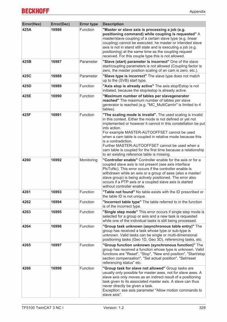
Appendix
TF5100 TwinCAT 3 NC I 329Version: 1.2
Error(Hex) Error(Dec) Error type Description425A 16986 Function "Master or slave axis is processing a job (e.g.
positioning command) while coupling is requested" Amaster/slave coupling of a certain slave type (e.g. linearcoupling) cannot be executed. he master or intended slaveaxis is not in stand still state and is executing a job (e.g.positioning) at the same time as the coupling requestreceived. For this couple type this is not allowed.
425B 16987 Parameter "Slave (start) parameter is incorrect" One of the slavestart/coupling parameters is not allowed (Coupling factor iszero, the master position scaling of an cam is zero, etc.).
425C 16988 Parameter "Slave type is incorrect" The slave type does not matchup to the (SVB) start type.
425D 16989 Function "Axis stop is already active" The axis stop/Estop is notinitiated, because the stop/estop is already active.
425E 16990 Function "Maximum number of tables per slavegeneratorreached" The maximum number of tables per slavegenerator is reached (e.g. "MC_MultiCamIn" is limited to 4tables).
425F 16991 Function "The scaling mode is invalid". The used scaling is invalidin this context. Either the mode is not defined or yet notimplemented or however it cannot in this constellation be putinto action.For example MASTER-AUTOOFFSET cannot be usedwhen a cam table is coupled in relative mode because thisis a contradiction.Further MASTER-AUTOOFFSET cannot be used when acam table is coupled for the first time because a relationshipto an existing reference table is missing.
4260 16992 Monitoring "Controller enable" Controller enable for the axis or for acoupled slave axis is not present (see axis interfacePlcToNc). This error occurs if the controller enable iswithdrawn while an axis or a group of axes (also a master/slave group) is being actively positioned. The error alsooccurs if a PTP axis or a coupled slave axis is startedwithout controller enable.
4261 16993 Function "Table not found" No table exists with the ID prescribed orthe table ID is not unique.
4262 16994 Function "Incorrect table type" The table referred to in the functionis of the incorrect type.
4263 16995 Function "Single step mode" This error occurs if single step mode isselected for a group or axis and a new task is requestedwhile one of the individual tasks is still being processed.
4264 16996 Function "Group task unknown (asynchronous table entry)" Thegroup has received a task whose type or sub-type isunknown. Valid tasks can be single or multi-dimensionalpositioning tasks (Geo 1D, Geo 3D), referencing tasks, etc.
4265 16997 Function "Group function unknown (synchronous function)" Thegroup has received a function whose type is unknown. Validfunctions are "Reset", "Stop", "New end position", "Start/stopsection compensation", "Set actual position", "Set/resetreferencing status" etc.
4266 16998 Function "Group task for slave not allowed" Group tasks areusually only possible for master axes, not for slave axes. Aslave axis only moves as an indirect result of a positioningtask given to its associated master axis. A slave can thusnever directly be given a task.Exception: see axis parameter "Allow motion commands toslave axis".
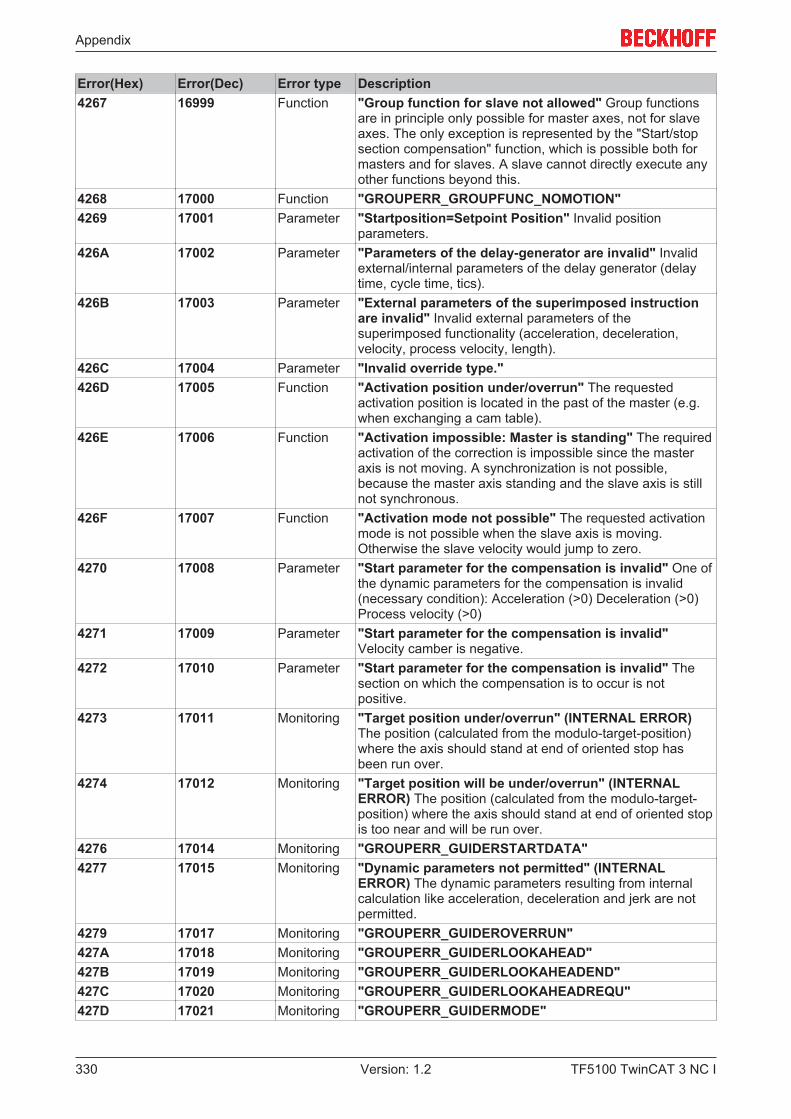
Appendix
TF5100 TwinCAT 3 NC I330 Version: 1.2
Error(Hex) Error(Dec) Error type Description4267 16999 Function "Group function for slave not allowed" Group functions
are in principle only possible for master axes, not for slaveaxes. The only exception is represented by the "Start/stopsection compensation" function, which is possible both formasters and for slaves. A slave cannot directly execute anyother functions beyond this.
4268 17000 Function "GROUPERR_GROUPFUNC_NOMOTION"4269 17001 Parameter "Startposition=Setpoint Position" Invalid position
parameters.426A 17002 Parameter "Parameters of the delay-generator are invalid" Invalid
external/internal parameters of the delay generator (delaytime, cycle time, tics).
426B 17003 Parameter "External parameters of the superimposed instructionare invalid" Invalid external parameters of thesuperimposed functionality (acceleration, deceleration,velocity, process velocity, length).
426C 17004 Parameter "Invalid override type."426D 17005 Function "Activation position under/overrun" The requested
activation position is located in the past of the master (e.g.when exchanging a cam table).
426E 17006 Function "Activation impossible: Master is standing" The requiredactivation of the correction is impossible since the masteraxis is not moving. A synchronization is not possible,because the master axis standing and the slave axis is stillnot synchronous.
426F 17007 Function "Activation mode not possible" The requested activationmode is not possible when the slave axis is moving.Otherwise the slave velocity would jump to zero.
4270 17008 Parameter "Start parameter for the compensation is invalid" One ofthe dynamic parameters for the compensation is invalid(necessary condition): Acceleration (>0) Deceleration (>0)Process velocity (>0)
4271 17009 Parameter "Start parameter for the compensation is invalid"Velocity camber is negative.
4272 17010 Parameter "Start parameter for the compensation is invalid" Thesection on which the compensation is to occur is notpositive.
4273 17011 Monitoring "Target position under/overrun" (INTERNAL ERROR)The position (calculated from the modulo-target-position)where the axis should stand at end of oriented stop hasbeen run over.
4274 17012 Monitoring "Target position will be under/overrun" (INTERNALERROR) The position (calculated from the modulo-target-position) where the axis should stand at end of oriented stopis too near and will be run over.
4276 17014 Monitoring "GROUPERR_GUIDERSTARTDATA"4277 17015 Monitoring "Dynamic parameters not permitted" (INTERNAL
ERROR) The dynamic parameters resulting from internalcalculation like acceleration, deceleration and jerk are notpermitted.
4279 17017 Monitoring "GROUPERR_GUIDEROVERRUN"427A 17018 Monitoring "GROUPERR_GUIDERLOOKAHEAD"427B 17019 Monitoring "GROUPERR_GUIDERLOOKAHEADEND"427C 17020 Monitoring "GROUPERR_GUIDERLOOKAHEADREQU"427D 17021 Monitoring "GROUPERR_GUIDERMODE"
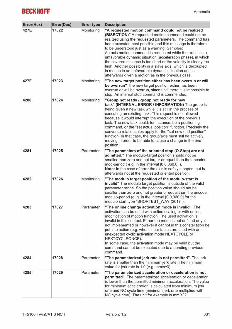
Appendix
TF5100 TwinCAT 3 NC I 331Version: 1.2
Error(Hex) Error(Dec) Error type Description427E 17022 Monitoring "A requested motion command could not be realized
(BISECTION)" A requested motion command could not berealized using the requested parameters. The command hasbeen executed best possible and this message is thereforeto be understood just as a warning. Samples:An axis motion command is requested while the axis is in aunfavorable dynamic situation (acceleration phase), in whichthe covered distance is too short or the velocity is clearly toohigh. Another possibility is a slave axis, which is decoupledin motion in an unfavorable dynamic situation and isafterwards given a motion as in the previous case.
427F 17023 Monitoring "The new target position either has been overrun or willbe overrun" The new target position either has beenoverrun or will be overrun, since until there it is impossible tostop. An internal stop command is commended.
4280 17024 Monitoring "Group not ready / group not ready for newtask" (INTERNAL ERROR / INFORMATION) The group isbeing given a new task while it is still in the process ofexecuting an existing task. This request is not allowedbecause it would interrupt the execution of the previoustask. The new task could, for instance, be a positioningcommand, or the "set actual position" function. Precisely theconverse relationships apply for the "set new end position"function. In that case, the group/axis must still be activelymoving in order to be able to cause a change in the endposition.
4281 17025 Parameter "The parameters of the oriented stop (O-Stop) are notadmitted." The modulo-target position should not besmaller than zero and not larger or equal than the encodermod-period ( e.g. in the interval [0.0,360.0] ).Note: In the case of error the axis is safely stopped, but isafterwards not at the requested oriented position.
4282 17026 Monitoring "The modulo target position of the modulo-start isinvalid" The modulo target position is outside of the validparameter range. So the position value should not besmaller than zero and not greater or equal than the encodermodulo-period (e. g. in the interval [0.0,360.0] for themodulo start type "SHORTEST_WAY (261)" ).
4283 17027 Parameter "The online change activation mode is invalid". Theactivation can be used with online scaling or with onlinemodification of motion function. The used activation isinvalid in this context. Either the mode is not defined or yetnot implemented or however it cannot in this constellation beput into action (e.g. when linear tables are used with anunexpected cyclic activation mode NEXTCYCLE orNEXTCYCLEONCE).In some case, the activation mode may be valid but thecommand cannot be executed due to a pending previouscommand.
4284 17028 Parameter "The parameterized jerk rate is not permitted". The jerkrate is smaller than the minimum jerk rate. The minimumvalue for jerk rate is 1.0 (e.g. mm/s^3).
4285 17029 Parameter "The parameterized acceleration or deceleration is notpermitted". The parameterized acceleration or decelerationis lower than the permitted minimum acceleration. The valuefor minimum acceleration is calculated from minimum jerkrate and NC cycle time (minimum jerk rate multiplied withNC cycle time). The unit for example is mm/s^2.
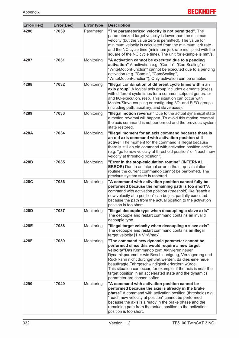
Appendix
TF5100 TwinCAT 3 NC I332 Version: 1.2
Error(Hex) Error(Dec) Error type Description4286 17030 Parameter "The parameterized velocity is not permitted". The
parameterized target velocity is lower than the minimumvelocity (but the value zero is permitted). The value forminimum velocity is calculated from the minimum jerk rateand the NC cycle time (minimum jerk rate multiplied with thesquare of the NC cycle time). The unit for example is mm/s.
4287 17031 Monitoring "A activation cannot be executed due to a pendingactivation" A activation e.g. "CamIn", "CamScaling" or"WriteMotionFunction" cannot be executed due to a pendingactivation (e.g. "CamIn", "CamScaling","WriteMotionFunction"). Only activation can be enabled.
4288 17032 Monitoring "Illegal combination of different cycle times within anaxis group" A logical axis group includes elements (axes)with different cycle times for a common setpoint generatorand I/O-execution, resp. This situation can occur withMaster/Slave-coupling or configuring 3D- and FIFO-groups(including path, auxiliary, and slave axes).
4289 17033 Monitoring "Illegal motion reversal" Due to the actual dynamical statea motion reversal will happen. To avoid this motion reversalthe axis command is not performed and the previous systemstate restored.
428A 17034 Monitoring "Illegal moment for an axis command because there isan old axis command with activation position stillactive" The moment for the command is illegal becausethere is still an old command with activation position active(e.g. "go to new velocity at threshold position" or "reach newvelocity at threshold position").
428B 17035 Monitoring "Error in the stop-calculation routine" (INTERNALERROR) Due to an internal error in the stop-calculationroutine the current commando cannot be performed. Theprevious system state is restored.
428C 17036 Monitoring "A command with activation position cannot fully beperformed because the remaining path is too short"Acommand with activation position (threshold) like "reach anew velocity at a position" can be just partially executedbecause the path from the actual position to the activationposition is too short.
428D 17037 Monitoring "Illegal decouple type when decoupling a slave axis"The decouple and restart command contains an invaliddecouple type.
428E 17038 Monitoring "Illegal target velocity when decoupling a slave axis"The decouple and restart command contains an illegaltarget velocity [1 < V <Vmax].
428F 17039 Monitoring "The command new dynamic parameter cannot beperformed since this would require a new targetvelocity"Das Kommando zum Aktivieren neuerDynamikparameter wie Beschleunigung, Verzögerung undRuck kann nicht durchgeführt werden, da dies eine neuebeauftragte Fahrgeschwindigkeit erfordern würde.This situation can occur, for example, if the axis is near thetarget position in an accelerated state and the dynamicsparameter are chosen softer.
4290 17040 Monitoring "A command with activation position cannot beperformed because the axis is already in the brakephase" A command with activation position (threshold) e.g."reach new velocity at position" cannot be performedbecause the axis is already in the brake phase and theremaining path from the actual position to the activationposition is too short.
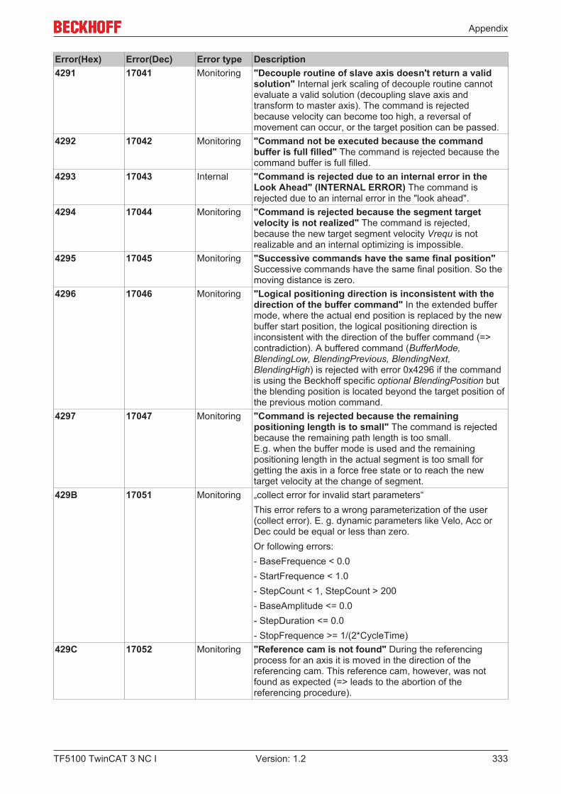
Appendix
TF5100 TwinCAT 3 NC I 333Version: 1.2
Error(Hex) Error(Dec) Error type Description4291 17041 Monitoring "Decouple routine of slave axis doesn't return a valid
solution" Internal jerk scaling of decouple routine cannotevaluate a valid solution (decoupling slave axis andtransform to master axis). The command is rejectedbecause velocity can become too high, a reversal ofmovement can occur, or the target position can be passed.
4292 17042 Monitoring "Command not be executed because the commandbuffer is full filled" The command is rejected because thecommand buffer is full filled.
4293 17043 Internal "Command is rejected due to an internal error in theLook Ahead" (INTERNAL ERROR) The command isrejected due to an internal error in the "look ahead".
4294 17044 Monitoring "Command is rejected because the segment targetvelocity is not realized" The command is rejected,because the new target segment velocity Vrequ is notrealizable and an internal optimizing is impossible.
4295 17045 Monitoring "Successive commands have the same final position"Successive commands have the same final position. So themoving distance is zero.
4296 17046 Monitoring "Logical positioning direction is inconsistent with thedirection of the buffer command" In the extended buffermode, where the actual end position is replaced by the newbuffer start position, the logical positioning direction isinconsistent with the direction of the buffer command (=>contradiction). A buffered command (BufferMode,BlendingLow, BlendingPrevious, BlendingNext,BlendingHigh) is rejected with error 0x4296 if the commandis using the Beckhoff specific optional BlendingPosition butthe blending position is located beyond the target position ofthe previous motion command.
4297 17047 Monitoring "Command is rejected because the remainingpositioning length is to small" The command is rejectedbecause the remaining path length is too small.E.g. when the buffer mode is used and the remainingpositioning length in the actual segment is too small forgetting the axis in a force free state or to reach the newtarget velocity at the change of segment.
429B 17051 Monitoring „collect error for invalid start parameters“This error refers to a wrong parameterization of the user(collect error). E. g. dynamic parameters like Velo, Acc orDec could be equal or less than zero.Or following errors:- BaseFrequence < 0.0- StartFrequence < 1.0- StepCount < 1, StepCount > 200- BaseAmplitude <= 0.0- StepDuration <= 0.0- StopFrequence >= 1/(2*CycleTime)
429C 17052 Monitoring "Reference cam is not found" During the referencingprocess for an axis it is moved in the direction of thereferencing cam. This reference cam, however, was notfound as expected (=> leads to the abortion of thereferencing procedure).

Appendix
TF5100 TwinCAT 3 NC I334 Version: 1.2
Error(Hex) Error(Dec) Error type Description429D 17053 Monitoring "Reference cam became not free" During the referencing
process for an axis it is moved in the direction of thereferencing cam, and is only stopped again when the camsignal is reached. After the axis has also come to a physicalstandstill, the axis is subsequently started regularly from thecam again. In this case, the reference cam did not becomefree again as expected when driving down (=> leads to theabortion of the referencing procedure).
429E 17054 Monitoring "IO sync pulse was not found (only when usinghardware latch)" If the hardware latch is activated, a syncpulse (zero pulse) is expected to be found and a sync eventtriggered following the expiry of a certain time or a certaindistance. If this is not the case, the reaction is an error andthe abortion of the referencing procedure.
42A0 17056 Internal "Group/axis consequential error" Consequential errorresulting from another causative error related to another axiswithin the group. Group/axis consequential errors can occurin relation to master/slave couplings or with multiple axisinterpolating DXD groups. If, for instance, it is detected thatthe following error limit of a master axis has been exceeded,then this consequential error is assigned to all the othermaster axes and slave axes in this group.
42A1 17057 Parameter "Velocity reduction factor for C0/C1 transition is notallowed" A C0 transition describes two geometries which,while they are themselves continuous, no not have eithercontinuous first or second differentials. The velocityreduction factor C0 acts on such transitions. Note: A C1transition is characterized by the two geometries beingcontinuous, but having only a first differential that iscontinuous. The velocity reduction factor C1 acts on suchtransitions.Value range: [0.0 ... 1.0] Unit: 1
42A2 17058 Parameter "Critical angle at segment transition not allowed"Value range: (0.0 ... 180.0] Unit: degree
42A3 17059 Parameter "Radius of the tolerance sphere" is in an invalid rangValue range: [0.0 ... 100.0] Unit: e.g. mm
42A4 17060 Parameter Not implemented.42A5 17061 Parameter "Start type"
Value range: [0,1] Unit: 142A6 17062 Parameter Not implemented.42A7 17063 Parameter "Blending" with given parameters not possible42A8 17064 Parameter Not implemented.42A9 17065 Parameter "Curve velocity reduction method not
allowed" (INTERNAL ERROR) The curve velocity reductionmethod does not exist.
42AA 17066 Parameter "Minimum velocity not allowed" The minimum velocitythat has been entered is less than 0.0.
42AB 17067 Parameter "Power function input not allowed" (INTERNAL ERROR)The input parameters in the power_() function lead to anFPU exception.
42AC 17068 Parameter "Dynamic change parameter not allowed" A parameterthat controls alterations to the dynamics is invalid.Parameter: 1. Absolute motion dynamics change: Allparameters must be strictly positive. 2. Relative reductionc_f: 0.0 < c_f <= 1.0
42AD 17069 Memory "Memory allocation error" (INTERNAL ERROR)
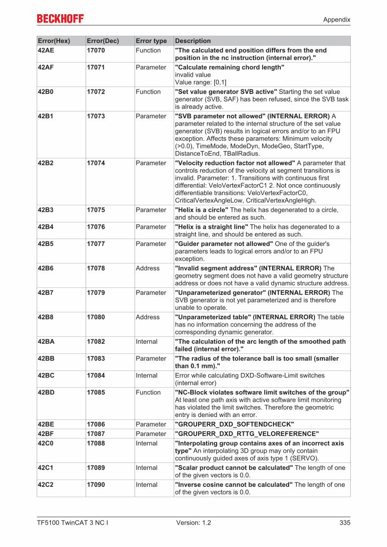
Appendix
TF5100 TwinCAT 3 NC I 335Version: 1.2
Error(Hex) Error(Dec) Error type Description42AE 17070 Function "The calculated end position differs from the end
position in the nc instruction (internal error)."42AF 17071 Parameter "Calculate remaining chord length"
invalid valueValue range: [0,1]
42B0 17072 Function "Set value generator SVB active" Starting the set valuegenerator (SVB, SAF) has been refused, since the SVB taskis already active.
42B1 17073 Parameter "SVB parameter not allowed" (INTERNAL ERROR) Aparameter related to the internal structure of the set valuegenerator (SVB) results in logical errors and/or to an FPUexception. Affects these parameters: Minimum velocity(>0.0), TimeMode, ModeDyn, ModeGeo, StartType,DistanceToEnd, TBallRadius.
42B2 17074 Parameter "Velocity reduction factor not allowed" A parameter thatcontrols reduction of the velocity at segment transitions isinvalid. Parameter: 1. Transitions with continuous firstdifferential: VeloVertexFactorC1 2. Not once continuouslydifferentiable transitions: VeloVertexFactorC0,CriticalVertexAngleLow, CriticalVertexAngleHigh.
42B3 17075 Parameter "Helix is a circle" The helix has degenerated to a circle,and should be entered as such.
42B4 17076 Parameter "Helix is a straight line" The helix has degenerated to astraight line, and should be entered as such.
42B5 17077 Parameter "Guider parameter not allowed" One of the guider'sparameters leads to logical errors and/or to an FPUexception.
42B6 17078 Address "Invalid segment address" (INTERNAL ERROR) Thegeometry segment does not have a valid geometry structureaddress or does not have a valid dynamic structure address.
42B7 17079 Parameter "Unparameterized generator" (INTERNAL ERROR) TheSVB generator is not yet parameterized and is thereforeunable to operate.
42B8 17080 Address "Unparameterized table" (INTERNAL ERROR) The tablehas no information concerning the address of thecorresponding dynamic generator.
42BA 17082 Internal "The calculation of the arc length of the smoothed pathfailed (internal error)."
42BB 17083 Parameter "The radius of the tolerance ball is too small (smallerthan 0.1 mm)."
42BC 17084 Internal Error while calculating DXD-Software-Limit switches(internal error)
42BD 17085 Function "NC-Block violates software limit switches of the group"At least one path axis with active software limit monitoringhas violated the limit switches. Therefore the geometricentry is denied with an error.
42BE 17086 Parameter "GROUPERR_DXD_SOFTENDCHECK"42BF 17087 Parameter "GROUPERR_DXD_RTTG_VELOREFERENCE"42C0 17088 Internal "Interpolating group contains axes of an incorrect axis
type" An interpolating 3D group may only containcontinuously guided axes of axis type 1 (SERVO).
42C1 17089 Internal "Scalar product cannot be calculated" The length of oneof the given vectors is 0.0.
42C2 17090 Internal "Inverse cosine cannot be calculated" The length of oneof the given vectors is 0.0.
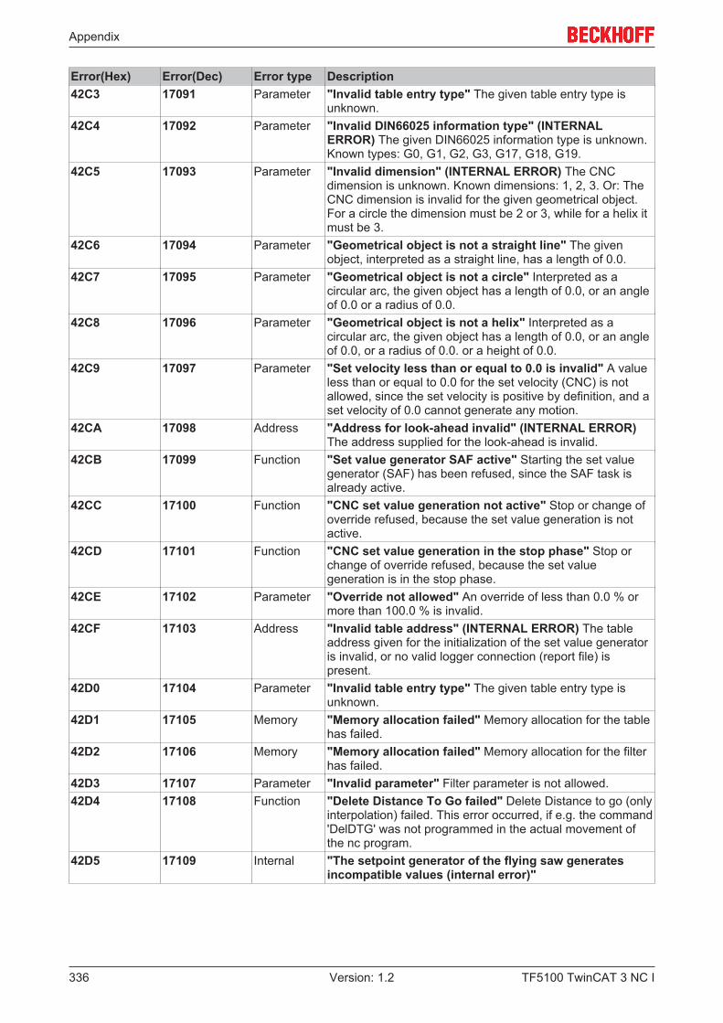
Appendix
TF5100 TwinCAT 3 NC I336 Version: 1.2
Error(Hex) Error(Dec) Error type Description42C3 17091 Parameter "Invalid table entry type" The given table entry type is
unknown.42C4 17092 Parameter "Invalid DIN66025 information type" (INTERNAL
ERROR) The given DIN66025 information type is unknown.Known types: G0, G1, G2, G3, G17, G18, G19.
42C5 17093 Parameter "Invalid dimension" (INTERNAL ERROR) The CNCdimension is unknown. Known dimensions: 1, 2, 3. Or: TheCNC dimension is invalid for the given geometrical object.For a circle the dimension must be 2 or 3, while for a helix itmust be 3.
42C6 17094 Parameter "Geometrical object is not a straight line" The givenobject, interpreted as a straight line, has a length of 0.0.
42C7 17095 Parameter "Geometrical object is not a circle" Interpreted as acircular arc, the given object has a length of 0.0, or an angleof 0.0 or a radius of 0.0.
42C8 17096 Parameter "Geometrical object is not a helix" Interpreted as acircular arc, the given object has a length of 0.0, or an angleof 0.0, or a radius of 0.0. or a height of 0.0.
42C9 17097 Parameter "Set velocity less than or equal to 0.0 is invalid" A valueless than or equal to 0.0 for the set velocity (CNC) is notallowed, since the set velocity is positive by definition, and aset velocity of 0.0 cannot generate any motion.
42CA 17098 Address "Address for look-ahead invalid" (INTERNAL ERROR)The address supplied for the look-ahead is invalid.
42CB 17099 Function "Set value generator SAF active" Starting the set valuegenerator (SAF) has been refused, since the SAF task isalready active.
42CC 17100 Function "CNC set value generation not active" Stop or change ofoverride refused, because the set value generation is notactive.
42CD 17101 Function "CNC set value generation in the stop phase" Stop orchange of override refused, because the set valuegeneration is in the stop phase.
42CE 17102 Parameter "Override not allowed" An override of less than 0.0 % ormore than 100.0 % is invalid.
42CF 17103 Address "Invalid table address" (INTERNAL ERROR) The tableaddress given for the initialization of the set value generatoris invalid, or no valid logger connection (report file) ispresent.
42D0 17104 Parameter "Invalid table entry type" The given table entry type isunknown.
42D1 17105 Memory "Memory allocation failed" Memory allocation for the tablehas failed.
42D2 17106 Memory "Memory allocation failed" Memory allocation for the filterhas failed.
42D3 17107 Parameter "Invalid parameter" Filter parameter is not allowed.42D4 17108 Function "Delete Distance To Go failed" Delete Distance to go (only
interpolation) failed. This error occurred, if e.g. the command'DelDTG' was not programmed in the actual movement ofthe nc program.
42D5 17109 Internal "The setpoint generator of the flying saw generatesincompatible values (internal error)"
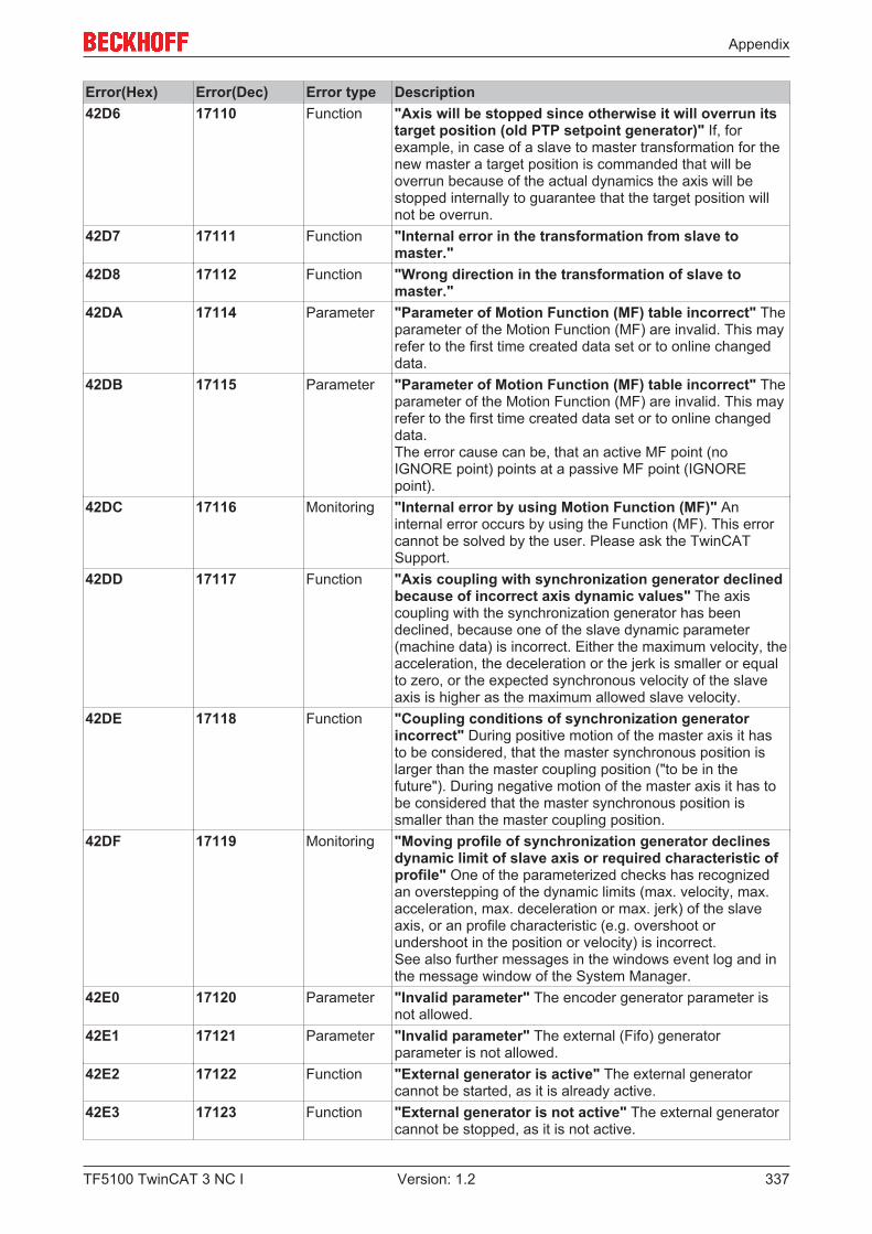
Appendix
TF5100 TwinCAT 3 NC I 337Version: 1.2
Error(Hex) Error(Dec) Error type Description42D6 17110 Function "Axis will be stopped since otherwise it will overrun its
target position (old PTP setpoint generator)" If, forexample, in case of a slave to master transformation for thenew master a target position is commanded that will beoverrun because of the actual dynamics the axis will bestopped internally to guarantee that the target position willnot be overrun.
42D7 17111 Function "Internal error in the transformation from slave tomaster."
42D8 17112 Function "Wrong direction in the transformation of slave tomaster."
42DA 17114 Parameter "Parameter of Motion Function (MF) table incorrect" Theparameter of the Motion Function (MF) are invalid. This mayrefer to the first time created data set or to online changeddata.
42DB 17115 Parameter "Parameter of Motion Function (MF) table incorrect" Theparameter of the Motion Function (MF) are invalid. This mayrefer to the first time created data set or to online changeddata.The error cause can be, that an active MF point (noIGNORE point) points at a passive MF point (IGNOREpoint).
42DC 17116 Monitoring "Internal error by using Motion Function (MF)" Aninternal error occurs by using the Function (MF). This errorcannot be solved by the user. Please ask the TwinCATSupport.
42DD 17117 Function "Axis coupling with synchronization generator declinedbecause of incorrect axis dynamic values" The axiscoupling with the synchronization generator has beendeclined, because one of the slave dynamic parameter(machine data) is incorrect. Either the maximum velocity, theacceleration, the deceleration or the jerk is smaller or equalto zero, or the expected synchronous velocity of the slaveaxis is higher as the maximum allowed slave velocity.
42DE 17118 Function "Coupling conditions of synchronization generatorincorrect" During positive motion of the master axis it hasto be considered, that the master synchronous position islarger than the master coupling position ("to be in thefuture"). During negative motion of the master axis it has tobe considered that the master synchronous position issmaller than the master coupling position.
42DF 17119 Monitoring "Moving profile of synchronization generator declinesdynamic limit of slave axis or required characteristic ofprofile" One of the parameterized checks has recognizedan overstepping of the dynamic limits (max. velocity, max.acceleration, max. deceleration or max. jerk) of the slaveaxis, or an profile characteristic (e.g. overshoot orundershoot in the position or velocity) is incorrect.See also further messages in the windows event log and inthe message window of the System Manager.
42E0 17120 Parameter "Invalid parameter" The encoder generator parameter isnot allowed.
42E1 17121 Parameter "Invalid parameter" The external (Fifo) generatorparameter is not allowed.
42E2 17122 Function "External generator is active" The external generatorcannot be started, as it is already active.
42E3 17123 Function "External generator is not active" The external generatorcannot be stopped, as it is not active.
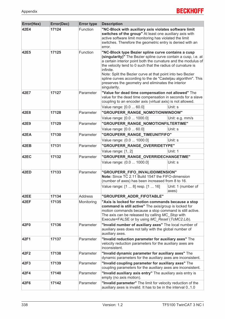
Appendix
TF5100 TwinCAT 3 NC I338 Version: 1.2
Error(Hex) Error(Dec) Error type Description42E4 17124 Function "NC-Block with auxiliary axis violates software limit
switches of the group" At least one auxiliary axis withactive software limit monitoring has violated the limitswitches. Therefore the geometric entry is denied with anerror.
42E5 17125 Function "NC-Block type Bezier spline curve contains a cusp(singularity)" The Bezier spline curve contain a cusp, i.e. ata certain interior point both the curvature and the modulus ofthe velocity tend to 0 such that the radius of curvature isinfinite.Note: Split the Bezier curve at that point into two Bezierspline curves according to the de "Casteljau algorithm". Thispreserves the geometry and eliminates the interiorsingularity.
42E7 17127 Parameter "Value for dead time compensation not allowed" Thevalue for the dead time compensation in seconds for a slavecoupling to an encoder axis (virtual axis) is not allowed.Value range: [0.0 ... 60.0] Unit: s
42E8 17128 Parameter "GROUPERR_RANGE_NOMOTIONWINDOW"Value range: [0.0 ... 1000.0] Unit: e.g. mm/s
42E9 17129 Parameter "GROUPERR_RANGE_NOMOTIONFILTERTIME"Value range: [0.0 ... 60.0] Unit: s
42EA 17130 Parameter "GROUPERR_RANGE_TIMEUNITFIFO"Value range: (0.0 ... 1000.0] Unit: s
42EB 17131 Parameter "GROUPERR_RANGE_OVERRIDETYPE"Value range: [1, 2] Unit: 1
42EC 17132 Parameter "GROUPERR_RANGE_OVERRIDECHANGETIME"Value range: (0.0 ... 1000.0] Unit: s
42ED 17133 Parameter "GROUPERR_FIFO_INVALIDDIMENSION"Note: Since TC 2.11 Build 1547 the FIFO-dimension(number of axes) has been increased from 8 to 16.Value range: [1 ... 8] resp. [1 ... 16] Unit: 1 (number of
axes)42EE 17134 Address "GROUPERR_ADDR_FIFOTABLE"42EF 17135 Monitoring "Axis is locked for motion commands because a stop
command is still active" The axis/group is locked formotion commands because a stop command is still active.The axis can be released by calling MC_Stop withExecute=FALSE or by using MC_Reset (TcMC2.Lib).
42F0 17136 Parameter "Invalid number of auxiliary axes" The local number ofauxiliary axes does not tally with the global number ofauxiliary axes.
42F1 17137 Parameter "Invalid reduction parameter for auxiliary axes" Thevelocity reduction parameters for the auxiliary axes areinconsistent.
42F2 17138 Parameter "Invalid dynamic parameter for auxiliary axes" Thedynamic parameters for the auxiliary axes are inconsistent.
42F3 17139 Parameter "Invalid coupling parameter for auxiliary axes" Thecoupling parameters for the auxiliary axes are inconsistent.
42F4 17140 Parameter "Invalid auxiliary axis entry" The auxiliary axis entry isempty (no axis motion).
42F6 17142 Parameter "Invalid parameter" The limit for velocity reduction of theauxiliary axes is invalid. It has to be in the interval 0..1.0
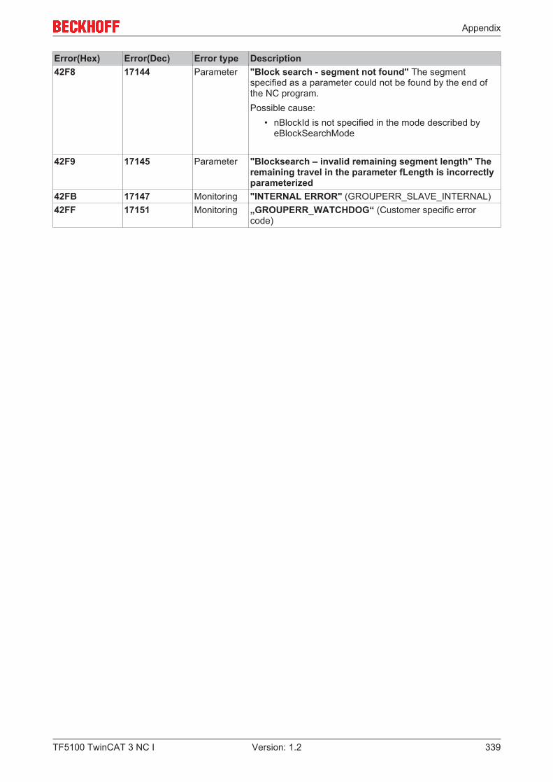
Appendix
TF5100 TwinCAT 3 NC I 339Version: 1.2
Error(Hex) Error(Dec) Error type Description42F8 17144 Parameter "Block search - segment not found" The segment
specified as a parameter could not be found by the end ofthe NC program.Possible cause:
• nBlockId is not specified in the mode described byeBlockSearchMode
42F9 17145 Parameter "Blocksearch – invalid remaining segment length" Theremaining travel in the parameter fLength is incorrectlyparameterized
42FB 17147 Monitoring "INTERNAL ERROR" (GROUPERR_SLAVE_INTERNAL)42FF 17151 Monitoring „GROUPERR_WATCHDOG“ (Customer specific error
code)

Appendix
TF5100 TwinCAT 3 NC I340 Version: 1.2
7.7.4 Axis Errors
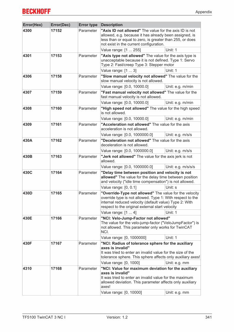
Appendix
TF5100 TwinCAT 3 NC I 341Version: 1.2
Error(Hex) Error(Dec) Error type Description4300 17152 Parameter "Axis ID not allowed" The value for the axis ID is not
allowed, e.g. because it has already been assigned, isless than or equal to zero, is greater than 255, or doesnot exist in the current configuration.Value range: [1 ... 255] Unit: 1
4301 17153 Parameter "Axis type not allowed" The value for the axis type isunacceptable because it is not defined. Type 1: ServoType 2: Fast/creep Type 3: Stepper motorValue range: [1 ... 3] Unit: 1
4306 17158 Parameter "Slow manual velocity not allowed" The value for theslow manual velocity is not allowed.Value range: [0.0, 10000.0] Unit: e.g. m/min
4307 17159 Parameter "Fast manual velocity not allowed" The value for thefast manual velocity is not allowed.Value range: [0.0, 10000.0] Unit: e.g. m/min
4308 17160 Parameter "High speed not allowed" The value for the high speedis not allowed.Value range: [0.0, 10000.0] Unit: e.g. m/min
4309 17161 Parameter "Acceleration not allowed" The value for the axisacceleration is not allowed.Value range: [0.0, 1000000.0] Unit: e.g. m/s/s
430A 17162 Parameter "Deceleration not allowed" The value for the axisdeceleration is not allowed.Value range: [0.0, 1000000.0] Unit: e.g. m/s/s
430B 17163 Parameter "Jerk not allowed" The value for the axis jerk is notallowed.Value range: [0.0, 1000000.0] Unit: e.g. m/s/s/s
430C 17164 Parameter "Delay time between position and velocity is notallowed" The value for the delay time between positionand velocity ("idle time compensation") is not allowed.Value range: [0, 0.1] Unit: s
430D 17165 Parameter "Override-Type not allowed" The value for the velocityoverride type is not allowed. Type 1: With respect to theinternal reduced velocity (default value) Type 2: Withrespect to the original external start velocityValue range: [1 ... 4] Unit: 1
430E 17166 Parameter "NCI: Velo-Jump-Factor not allowed" The value for the velo-jump-factor ("VeloJumpFactor") isnot allowed. This parameter only works for TwinCATNCI.Value range: [0, 1000000] Unit: 1
430F 17167 Parameter "NCI: Radius of tolerance sphere for the auxiliaryaxes is invalid" It was tried to enter an invalid value for the size of thetolerance sphere. This sphere affects only auxiliary axes!Value range: [0, 1000] Unit: e.g. mm
4310 17168 Parameter "NCI: Value for maximum deviation for the auxiliaryaxes is invalid" It was tried to enter an invalid value for the maximumallowed deviation. This parameter affects only auxiliaryaxes!Value range: [0, 10000] Unit: e.g. mm
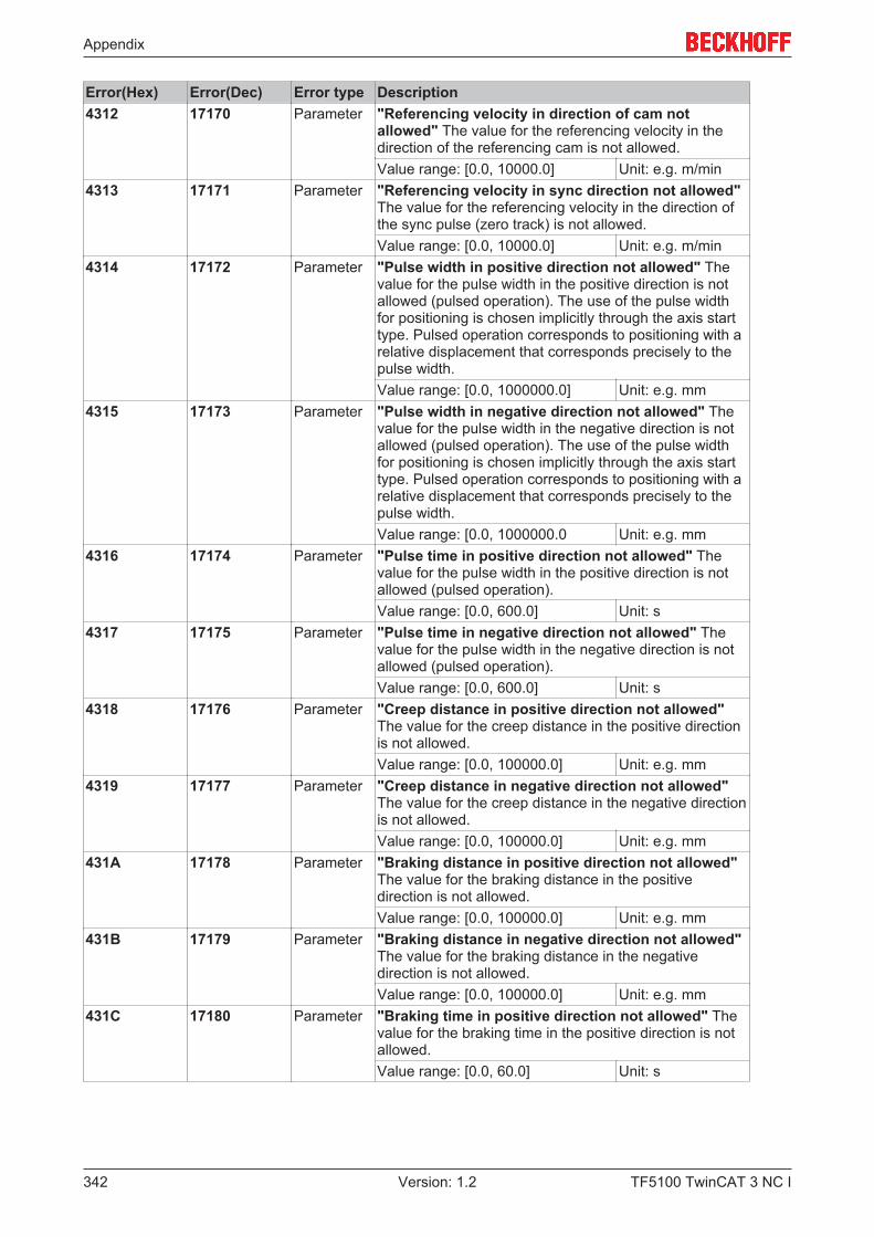
Appendix
TF5100 TwinCAT 3 NC I342 Version: 1.2
Error(Hex) Error(Dec) Error type Description4312 17170 Parameter "Referencing velocity in direction of cam not
allowed" The value for the referencing velocity in thedirection of the referencing cam is not allowed.Value range: [0.0, 10000.0] Unit: e.g. m/min
4313 17171 Parameter "Referencing velocity in sync direction not allowed"The value for the referencing velocity in the direction ofthe sync pulse (zero track) is not allowed.Value range: [0.0, 10000.0] Unit: e.g. m/min
4314 17172 Parameter "Pulse width in positive direction not allowed" Thevalue for the pulse width in the positive direction is notallowed (pulsed operation). The use of the pulse widthfor positioning is chosen implicitly through the axis starttype. Pulsed operation corresponds to positioning with arelative displacement that corresponds precisely to thepulse width.Value range: [0.0, 1000000.0] Unit: e.g. mm
4315 17173 Parameter "Pulse width in negative direction not allowed" Thevalue for the pulse width in the negative direction is notallowed (pulsed operation). The use of the pulse widthfor positioning is chosen implicitly through the axis starttype. Pulsed operation corresponds to positioning with arelative displacement that corresponds precisely to thepulse width.Value range: [0.0, 1000000.0 Unit: e.g. mm
4316 17174 Parameter "Pulse time in positive direction not allowed" Thevalue for the pulse width in the positive direction is notallowed (pulsed operation).Value range: [0.0, 600.0] Unit: s
4317 17175 Parameter "Pulse time in negative direction not allowed" Thevalue for the pulse width in the negative direction is notallowed (pulsed operation).Value range: [0.0, 600.0] Unit: s
4318 17176 Parameter "Creep distance in positive direction not allowed"The value for the creep distance in the positive directionis not allowed.Value range: [0.0, 100000.0] Unit: e.g. mm
4319 17177 Parameter "Creep distance in negative direction not allowed"The value for the creep distance in the negative directionis not allowed.Value range: [0.0, 100000.0] Unit: e.g. mm
431A 17178 Parameter "Braking distance in positive direction not allowed"The value for the braking distance in the positivedirection is not allowed.Value range: [0.0, 100000.0] Unit: e.g. mm
431B 17179 Parameter "Braking distance in negative direction not allowed"The value for the braking distance in the negativedirection is not allowed.Value range: [0.0, 100000.0] Unit: e.g. mm
431C 17180 Parameter "Braking time in positive direction not allowed" Thevalue for the braking time in the positive direction is notallowed.Value range: [0.0, 60.0] Unit: s
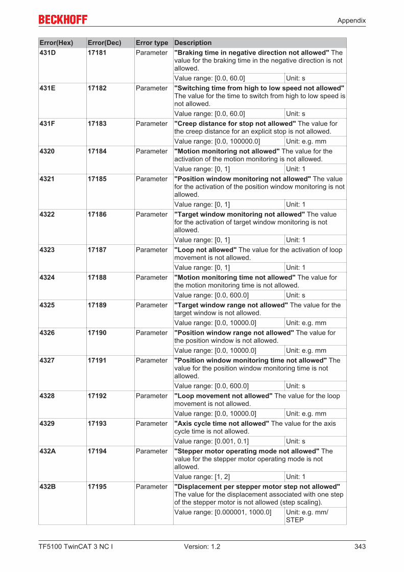
Appendix
TF5100 TwinCAT 3 NC I 343Version: 1.2
Error(Hex) Error(Dec) Error type Description431D 17181 Parameter "Braking time in negative direction not allowed" The
value for the braking time in the negative direction is notallowed.Value range: [0.0, 60.0] Unit: s
431E 17182 Parameter "Switching time from high to low speed not allowed"The value for the time to switch from high to low speed isnot allowed.Value range: [0.0, 60.0] Unit: s
431F 17183 Parameter "Creep distance for stop not allowed" The value forthe creep distance for an explicit stop is not allowed.Value range: [0.0, 100000.0] Unit: e.g. mm
4320 17184 Parameter "Motion monitoring not allowed" The value for theactivation of the motion monitoring is not allowed.Value range: [0, 1] Unit: 1
4321 17185 Parameter "Position window monitoring not allowed" The valuefor the activation of the position window monitoring is notallowed.Value range: [0, 1] Unit: 1
4322 17186 Parameter "Target window monitoring not allowed" The valuefor the activation of target window monitoring is notallowed.Value range: [0, 1] Unit: 1
4323 17187 Parameter "Loop not allowed" The value for the activation of loopmovement is not allowed.Value range: [0, 1] Unit: 1
4324 17188 Parameter "Motion monitoring time not allowed" The value forthe motion monitoring time is not allowed.Value range: [0.0, 600.0] Unit: s
4325 17189 Parameter "Target window range not allowed" The value for thetarget window is not allowed.Value range: [0.0, 10000.0] Unit: e.g. mm
4326 17190 Parameter "Position window range not allowed" The value forthe position window is not allowed.Value range: [0.0, 10000.0] Unit: e.g. mm
4327 17191 Parameter "Position window monitoring time not allowed" Thevalue for the position window monitoring time is notallowed.Value range: [0.0, 600.0] Unit: s
4328 17192 Parameter "Loop movement not allowed" The value for the loopmovement is not allowed.Value range: [0.0, 10000.0] Unit: e.g. mm
4329 17193 Parameter "Axis cycle time not allowed" The value for the axiscycle time is not allowed.Value range: [0.001, 0.1] Unit: s
432A 17194 Parameter "Stepper motor operating mode not allowed" Thevalue for the stepper motor operating mode is notallowed.Value range: [1, 2] Unit: 1
432B 17195 Parameter "Displacement per stepper motor step not allowed"The value for the displacement associated with one stepof the stepper motor is not allowed (step scaling).Value range: [0.000001, 1000.0] Unit: e.g. mm/
STEP

Appendix
TF5100 TwinCAT 3 NC I344 Version: 1.2
Error(Hex) Error(Dec) Error type Description432C 17196 Parameter "Minimum speed for stepper motor set value profile
not allowed" The value for the minimum speed of thestepper motor speed profile is not allowed.Value range: [0.0, 1000.0] Unit: z. B. m/min
432D 17197 Parameter "Stepper motor stages for one speed stage notallowed" The value for the number of steps for eachspeed stage in the set value generation is not allowed.Value range: [0, 100] Unit: 1
432E 17198 Parameter "DWORD for the interpretation of the axis units notallowed" The value that contains the flags for theinterpretation of the position and velocity units is notallowed.Value range: [0, 0xFFFFFFFF] Unit: 1
432F 17199 Parameter "Maximum velocity not allowed" The value for themaximum permitted velocity is not allowed.Value range: [0.0, 10000.0] Unit: e.g. m/min
4330 17200 Parameter "Motion monitoring window not allowed" The valuefor the motion monitoring window is not allowed.Value range: [0.0, 10000.0] Unit: e.g. mm
4331 17201 Parameter "PEH time monitoring not allowed" The value for theactivation of the PEH time monitoring is not allowed(PEH: positioning end and halt).Value range: [0, 1] Unit: 1
4332 17202 Parameter "PEH monitoring time not allowed" The value for thePEH monitoring time (timeout) is not allowed (PEH:positioning end and halt). default value: 5sValue range: [0.0, 600.0] Unit: s
4333 17203 Parameter "AXISERR_RANGE_DELAYBREAKRELEASE"4334 17204 Parameter "AXISERR_RANGE_DATAPERSISTENCE"433A 17210 Parameter "AXISERR_RANGE_POSDIFF_FADING_ACCELERAT
ION"433B 17211 Parameter "Fast Axis Stop Signal Type not allowed" The value
for the Signal Type of the 'Fast Axis Stop' is not allowed[0...5].
4340 17216 Initialization "Axis initialization" Axis has not been initialized.Although the axis has been created, the rest of theinitialization has not been performed (1. Initialization ofaxis I/O, 2. Initialization of axis, 3. Reset axis).
4341 17217 Address "Group address" Axis does not have a group, or thegroup address has not been initialized (group containsthe set value generation).
4342 17218 Address "Encoder address" The axis does not have anencoder, or the encoder address has not been initialized.
4343 17219 Address "Controller address" The axis does not have acontroller, or the controller address has not beeninitialized.
4344 17220 Address "Drive address" The axis does not have a drive, or thedrive address has not been initialized.
4345 17221 Address "Axis interface PLC to NC address" Axis does nothave an axis interface from the PLC to the NC, or theaxis interface address has not been initialized.
4346 17222 Address "Axis interface NC to PLC address" Axis does nothave an axis interface from the NC to the PLC, or theaxis interface address has not been initialized.
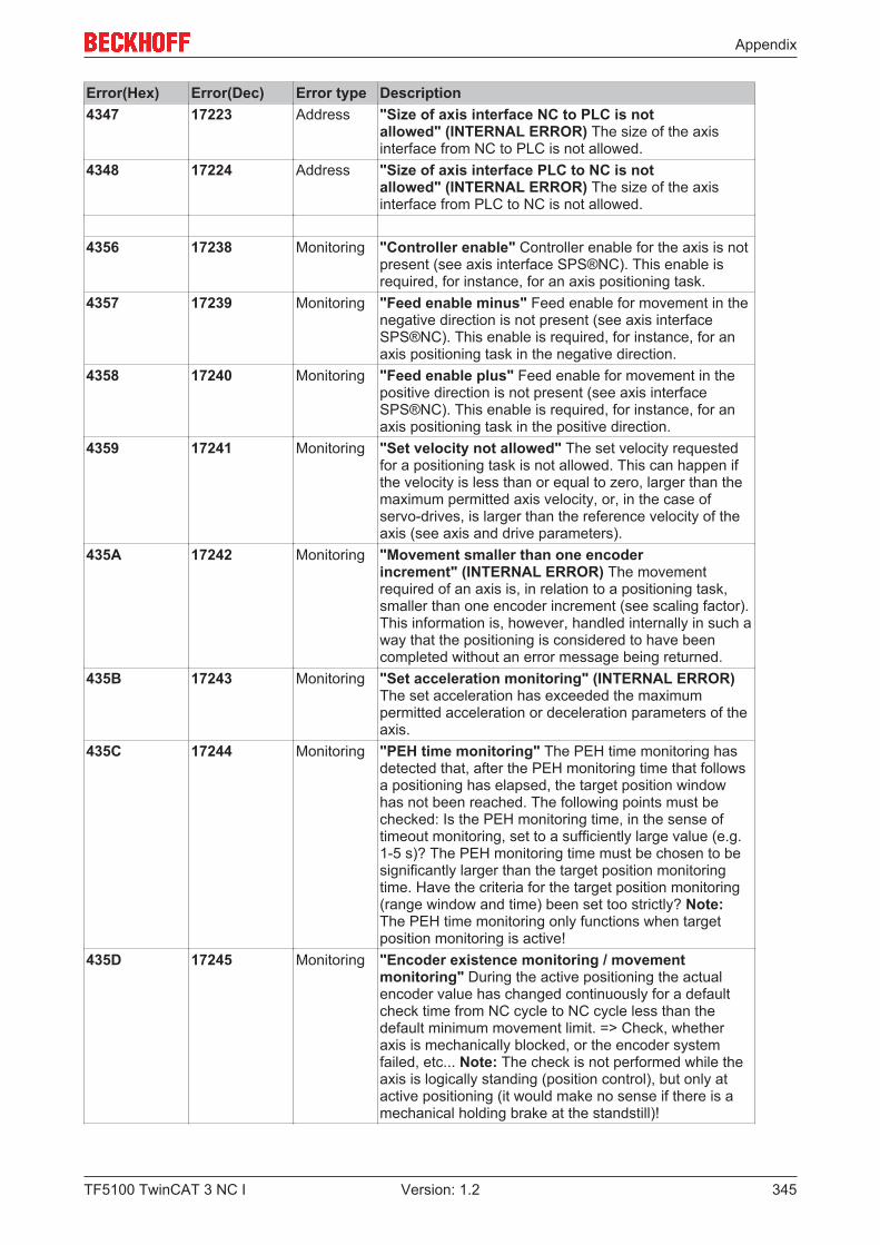
Appendix
TF5100 TwinCAT 3 NC I 345Version: 1.2
Error(Hex) Error(Dec) Error type Description4347 17223 Address "Size of axis interface NC to PLC is not
allowed" (INTERNAL ERROR) The size of the axisinterface from NC to PLC is not allowed.
4348 17224 Address "Size of axis interface PLC to NC is notallowed" (INTERNAL ERROR) The size of the axisinterface from PLC to NC is not allowed.
4356 17238 Monitoring "Controller enable" Controller enable for the axis is notpresent (see axis interface SPS®NC). This enable isrequired, for instance, for an axis positioning task.
4357 17239 Monitoring "Feed enable minus" Feed enable for movement in thenegative direction is not present (see axis interfaceSPS®NC). This enable is required, for instance, for anaxis positioning task in the negative direction.
4358 17240 Monitoring "Feed enable plus" Feed enable for movement in thepositive direction is not present (see axis interfaceSPS®NC). This enable is required, for instance, for anaxis positioning task in the positive direction.
4359 17241 Monitoring "Set velocity not allowed" The set velocity requestedfor a positioning task is not allowed. This can happen ifthe velocity is less than or equal to zero, larger than themaximum permitted axis velocity, or, in the case ofservo-drives, is larger than the reference velocity of theaxis (see axis and drive parameters).
435A 17242 Monitoring "Movement smaller than one encoderincrement" (INTERNAL ERROR) The movementrequired of an axis is, in relation to a positioning task,smaller than one encoder increment (see scaling factor).This information is, however, handled internally in such away that the positioning is considered to have beencompleted without an error message being returned.
435B 17243 Monitoring "Set acceleration monitoring" (INTERNAL ERROR)The set acceleration has exceeded the maximumpermitted acceleration or deceleration parameters of theaxis.
435C 17244 Monitoring "PEH time monitoring" The PEH time monitoring hasdetected that, after the PEH monitoring time that followsa positioning has elapsed, the target position windowhas not been reached. The following points must bechecked: Is the PEH monitoring time, in the sense oftimeout monitoring, set to a sufficiently large value (e.g.1-5 s)? The PEH monitoring time must be chosen to besignificantly larger than the target position monitoringtime. Have the criteria for the target position monitoring(range window and time) been set too strictly? Note:The PEH time monitoring only functions when targetposition monitoring is active!
435D 17245 Monitoring "Encoder existence monitoring / movementmonitoring" During the active positioning the actualencoder value has changed continuously for a defaultcheck time from NC cycle to NC cycle less than thedefault minimum movement limit. => Check, whetheraxis is mechanically blocked, or the encoder systemfailed, etc... Note: The check is not performed while theaxis is logically standing (position control), but only atactive positioning (it would make no sense if there is amechanical holding brake at the standstill)!
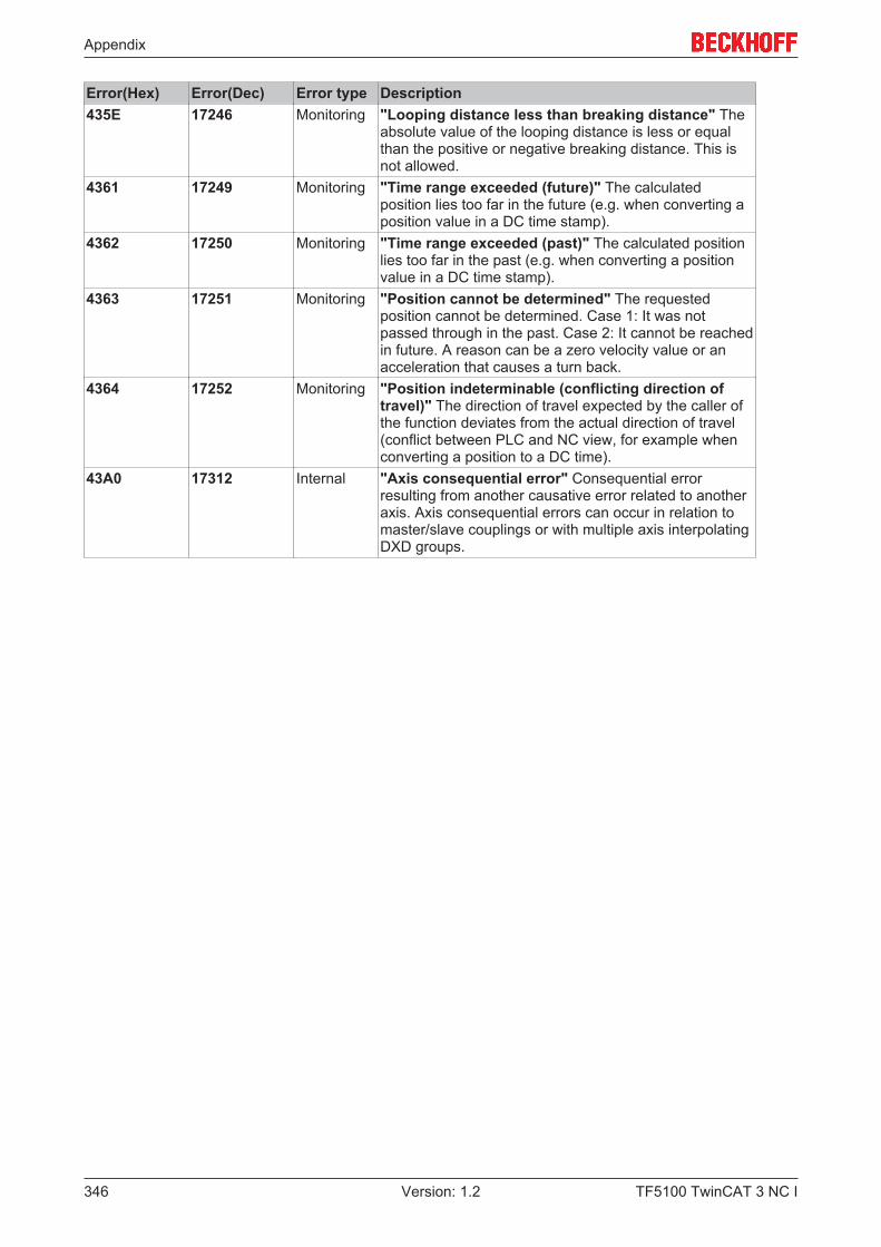
Appendix
TF5100 TwinCAT 3 NC I346 Version: 1.2
Error(Hex) Error(Dec) Error type Description435E 17246 Monitoring "Looping distance less than breaking distance" The
absolute value of the looping distance is less or equalthan the positive or negative breaking distance. This isnot allowed.
4361 17249 Monitoring "Time range exceeded (future)" The calculatedposition lies too far in the future (e.g. when converting aposition value in a DC time stamp).
4362 17250 Monitoring "Time range exceeded (past)" The calculated positionlies too far in the past (e.g. when converting a positionvalue in a DC time stamp).
4363 17251 Monitoring "Position cannot be determined" The requestedposition cannot be determined. Case 1: It was notpassed through in the past. Case 2: It cannot be reachedin future. A reason can be a zero velocity value or anacceleration that causes a turn back.
4364 17252 Monitoring "Position indeterminable (conflicting direction oftravel)" The direction of travel expected by the caller ofthe function deviates from the actual direction of travel(conflict between PLC and NC view, for example whenconverting a position to a DC time).
43A0 17312 Internal "Axis consequential error" Consequential errorresulting from another causative error related to anotheraxis. Axis consequential errors can occur in relation tomaster/slave couplings or with multiple axis interpolatingDXD groups.
Appendix
TF5100 TwinCAT 3 NC I 347Version: 1.2
7.7.5 Encoder Errors
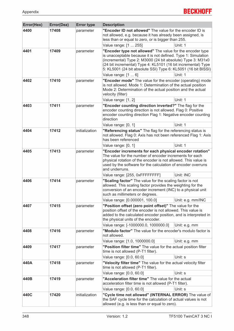
Appendix
TF5100 TwinCAT 3 NC I348 Version: 1.2
Error(Hex) Error(Dez) Error type Description4400 17408 parameter "Encoder ID not allowed" The value for the encoder ID is
not allowed, e.g. because it has already been assigned, isless than or equal to zero, or is bigger than 255.Value range: [1 ... 255] Unit: 1
4401 17409 parameter "Encoder type not allowed" The value for the encoder typeis unacceptable because it is not defined. Type 1: Simulation(incremental) Type 2: M3000 (24 bit absolute) Type 3: M31x0(24 bit incremental) Type 4: KL5101 (16 bit incremental) Type5: KL5001 (24 bit absolute SSI) Type 6: KL5051 (16 bit BISSI)Value range: [1 ... 6] Unit: 1
4402 17410 parameter "Encoder mode" The value for the encoder (operating) modeis not allowed. Mode 1: Determination of the actual positionMode 2: Determination of the actual position and the actualvelocity (filter)Value range: [1, 2] Unit: 1
4403 17411 parameter "Encoder counting direction inverted?" The flag for theencoder counting direction is not allowed. Flag 0: Positiveencoder counting direction Flag 1: Negative encoder countingdirectionValue range: [0, 1] Unit: 1
4404 17412 initialization "Referencing status" The flag for the referencing status isnot allowed. Flag 0: Axis has not been referenced Flag 1: Axishas been referencedValue range: [0, 1] Unit: 1
4405 17413 parameter "Encoder increments for each physical encoder rotation"The value for the number of encoder increments for eachphysical rotation of the encoder is not allowed. This value isused by the software for the calculation of encoder overrunsand underruns.Value range: [255, 0xFFFFFFFF] Unit: INC
4406 17414 parameter "Scaling factor" The value for the scaling factor is notallowed. This scaling factor provides the weighting for theconversion of an encoder increment (INC) to a physical unitsuch as millimeters or degrees.Value range: [0.000001, 100.0] Unit: e.g. mm/INC
4407 17415 parameter "Position offset (zero point offset)" The value for theposition offset of the encoder is not allowed. This value isadded to the calculated encoder position, and is interpreted inthe physical units of the encoder.Value range: [-1000000.0, 1000000.0] Unit: e.g. mm
4408 17416 parameter "Modulo factor" The value for the encoder's modulo factor isnot allowed.Value range: [1.0, 1000000.0] Unit: e.g. mm
4409 17417 parameter "Position filter time" The value for the actual position filtertime is not allowed (P-T1 filter).Value range: [0.0, 60.0] Unit: s
440A 17418 parameter "Velocity filter time" The value for the actual velocity filtertime is not allowed (P-T1 filter).Value range: [0.0, 60.0] Unit: s
440B 17419 parameter "Acceleration filter time" The value for the actualacceleration filter time is not allowed (P-T1 filter).Value range: [0.0, 60.0] Unit: s
440C 17420 initialization "Cycle time not allowed" (INTERNAL ERROR) The value ofthe SAF cycle time for the calculation of actual values is notallowed (e.g. is less than or equal to zero).
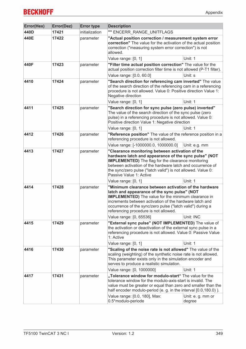
Appendix
TF5100 TwinCAT 3 NC I 349Version: 1.2
Error(Hex) Error(Dez) Error type Description440D 17421 initialization "" ENCERR_RANGE_UNITFLAGS440E 17422 parameter "Actual position correction / measurement system error
correction" The value for the activation of the actual positioncorrection ("measuring system error correction") is notallowed.Value range: [0, 1] Unit: 1
440F 17423 parameter "Filter time actual position correction" The value for theactual position correction filter time is not allowed (P-T1 filter).Value range: [0.0, 60.0] Unit: s
4410 17424 parameter "Search direction for referencing cam inverted" The valueof the search direction of the referencing cam in a referencingprocedure is not allowed. Value 0: Positive direction Value 1:Negative directionValue range: [0, 1] Unit: 1
4411 17425 parameter "Search direction for sync pulse (zero pulse) inverted"The value of the search direction of the sync pulse (zeropulse) in a referencing procedure is not allowed. Value 0:Positive direction Value 1: Negative directionValue range: [0, 1] Unit: 1
4412 17426 parameter "Reference position" The value of the reference position in areferencing procedure is not allowed.Value range: [-1000000.0, 1000000.0] Unit: e.g. mm
4413 17427 parameter "Clearance monitoring between activation of thehardware latch and appearance of the sync pulse" (NOTIMPLEMENTED) The flag for the clearance monitoringbetween activation of the hardware latch and occurrence ofthe sync/zero pulse ("latch valid") is not allowed. Value 0:Passive Value 1: ActiveValue range: [0, 1] Unit: 1
4414 17428 parameter "Minimum clearance between activation of the hardwarelatch and appearance of the sync pulse" (NOTIMPLEMENTED) The value for the minimum clearance inincrements between activation of the hardware latch andoccurrence of the sync/zero pulse ("latch valid") during areferencing procedure is not allowed.Value range: [0, 65536] Unit: INC
4415 17429 parameter "External sync pulse" (NOT IMPLEMENTED) The value ofthe activation or deactivation of the external sync pulse in areferencing procedure is not allowed. Value 0: Passive Value1: ActiveValue range: [0, 1] Unit: 1
4416 17430 parameter "Scaling of the noise rate is not allowed" The value of thescaling (weighting) of the synthetic noise rate is not allowed.This parameter exists only in the simulation encoder andserves to produce a realistic simulation.Value range: [0, 1000000] Unit: 1
4417 17431 parameter „Tolerance window for modulo-start“ The value for thetolerance window for the modulo-axis-start is invalid. Thevalue must be greater or equal than zero and smaller than thehalf encoder modulo-period (e. g. in the interval [0.0,180.0) ).Value range: [0.0, 180], Max:0.5*modulo-periode
Unit: e. g. mm ordegree
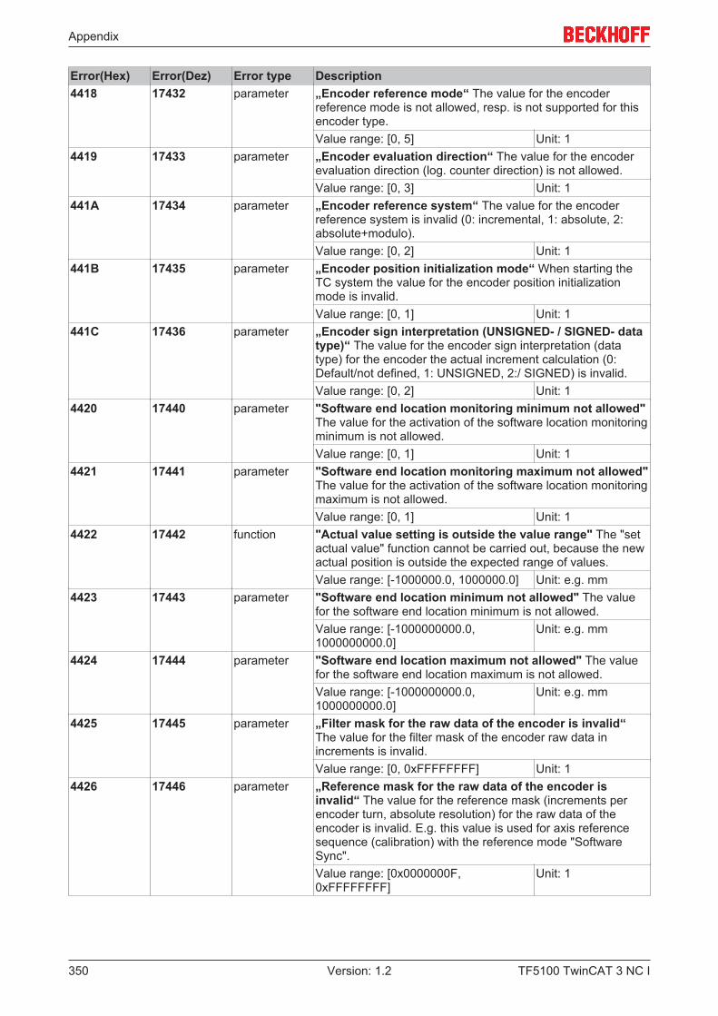
Appendix
TF5100 TwinCAT 3 NC I350 Version: 1.2
Error(Hex) Error(Dez) Error type Description4418 17432 parameter „Encoder reference mode“ The value for the encoder
reference mode is not allowed, resp. is not supported for thisencoder type.Value range: [0, 5] Unit: 1
4419 17433 parameter „Encoder evaluation direction“ The value for the encoderevaluation direction (log. counter direction) is not allowed.Value range: [0, 3] Unit: 1
441A 17434 parameter „Encoder reference system“ The value for the encoderreference system is invalid (0: incremental, 1: absolute, 2:absolute+modulo).Value range: [0, 2] Unit: 1
441B 17435 parameter „Encoder position initialization mode“ When starting theTC system the value for the encoder position initializationmode is invalid.Value range: [0, 1] Unit: 1
441C 17436 parameter „Encoder sign interpretation (UNSIGNED- / SIGNED- datatype)“ The value for the encoder sign interpretation (datatype) for the encoder the actual increment calculation (0:Default/not defined, 1: UNSIGNED, 2:/ SIGNED) is invalid.Value range: [0, 2] Unit: 1
4420 17440 parameter "Software end location monitoring minimum not allowed"The value for the activation of the software location monitoringminimum is not allowed.Value range: [0, 1] Unit: 1
4421 17441 parameter "Software end location monitoring maximum not allowed"The value for the activation of the software location monitoringmaximum is not allowed.Value range: [0, 1] Unit: 1
4422 17442 function "Actual value setting is outside the value range" The "setactual value" function cannot be carried out, because the newactual position is outside the expected range of values.Value range: [-1000000.0, 1000000.0] Unit: e.g. mm
4423 17443 parameter "Software end location minimum not allowed" The valuefor the software end location minimum is not allowed.Value range: [-1000000000.0,1000000000.0]
Unit: e.g. mm
4424 17444 parameter "Software end location maximum not allowed" The valuefor the software end location maximum is not allowed.Value range: [-1000000000.0,1000000000.0]
Unit: e.g. mm
4425 17445 parameter „Filter mask for the raw data of the encoder is invalid“The value for the filter mask of the encoder raw data inincrements is invalid.Value range: [0, 0xFFFFFFFF] Unit: 1
4426 17446 parameter „Reference mask for the raw data of the encoder isinvalid“ The value for the reference mask (increments perencoder turn, absolute resolution) for the raw data of theencoder is invalid. E.g. this value is used for axis referencesequence (calibration) with the reference mode "SoftwareSync".Value range: [0x0000000F,0xFFFFFFFF]
Unit: 1

Appendix
TF5100 TwinCAT 3 NC I 351Version: 1.2
Error(Hex) Error(Dez) Error type Description4430 17456 function "Hardware latch activation (encoder)" Activation of the
encoder hardware latch was implicitly initiated by thereferencing procedure. If this function has already beenactivated but a latch value has not yet become valid ("latchvalid"), another call to the function is refused with this error.
4431 17457 function "External hardware latch activation (encoder)" Theactivation of the external hardware latch (only available on theKL5101) is initiated explicitly by an ADS command (calledfrom the PLC program of the Visual Basic interface). If thisfunction has already been activated, but the latch value hasnot yet been made valid by an external signal ("external latchvalid"), another call to the function is refused with this error.
4432 17458 function "External hardware latch activation (encoder)" If areferencing procedure has previously been initiated and thehardware still signals a valid latch value ("latch valid"), thisfunction must not be called. In practice, however, this errorcan almost never occur.
4433 17459 function "External hardware latch activation (encoder)" If thisfunction has already been initiated and the hardware is stillsignaling that the external latch value is still valid ("externlatch valid"), a further activation should not be carried out andthe commando will be declined with an error (the internalhandshake communication between NC and IO device is stillactive). In that case the validity of the external hardware latchwould immediately be signaled, although the old latch valuewould still be present.
4434 17460 monitoring "Encoder function not supported" An encoder function hasbeen activated that is currently not released for use, or whichis not even implemented.
4435 17461 monitoring „Encoder function is already active“ An encoder functioncan not been activated because this functionality is alreadyactive.
4440 17472 initialization "Encoder initialization" Encoder has not been initialized.Although the axis has been created, the rest of theinitialization has not been performed (1. Initialization of axis I/O, 2. Initialization of axis, 3. Reset axis).
4441 17473 address "Axis address" The encoder does not have an axis, or theaxis address has not been initialized.
4442 17474 address "I/O input structure address" The drive does not have avalid I/O input address in the process image.
4443 17475 address "I/O output structure address" The encoder does not havea valid I/O output address in the process image.
4450 17488 monitoring "Encoder counter underflow monitoring" The encoder'sincremental counter has underflowed.
4451 17489 monitoring "Encoder counter overflow monitoring" The encoder'sincremental counter has overflowed.
4460 17504 monitoring "Software end location minimum (axis start)" With activemonitoring of the software end location for a minimum, a starthas been made from a position that lies below the softwareend location minimum.
4461 17505 monitoring "Software end location maximum (axis start)" With activemonitoring of the software end location for a maximum, a starthas been made from a position that lies above the softwareend location maximum.
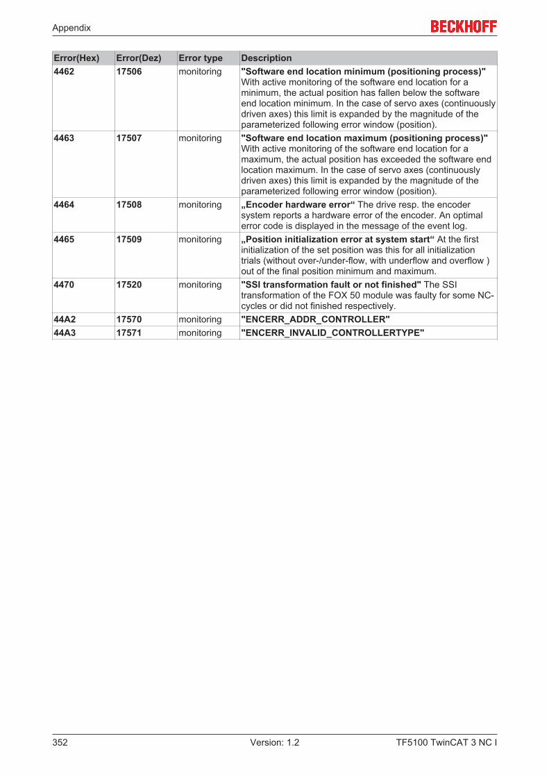
Appendix
TF5100 TwinCAT 3 NC I352 Version: 1.2
Error(Hex) Error(Dez) Error type Description4462 17506 monitoring "Software end location minimum (positioning process)"
With active monitoring of the software end location for aminimum, the actual position has fallen below the softwareend location minimum. In the case of servo axes (continuouslydriven axes) this limit is expanded by the magnitude of theparameterized following error window (position).
4463 17507 monitoring "Software end location maximum (positioning process)"With active monitoring of the software end location for amaximum, the actual position has exceeded the software endlocation maximum. In the case of servo axes (continuouslydriven axes) this limit is expanded by the magnitude of theparameterized following error window (position).
4464 17508 monitoring „Encoder hardware error“ The drive resp. the encodersystem reports a hardware error of the encoder. An optimalerror code is displayed in the message of the event log.
4465 17509 monitoring „Position initialization error at system start“ At the firstinitialization of the set position was this for all initializationtrials (without over-/under-flow, with underflow and overflow )out of the final position minimum and maximum.
4470 17520 monitoring "SSI transformation fault or not finished" The SSItransformation of the FOX 50 module was faulty for some NC-cycles or did not finished respectively.
44A2 17570 monitoring "ENCERR_ADDR_CONTROLLER"44A3 17571 monitoring "ENCERR_INVALID_CONTROLLERTYPE"
Appendix
TF5100 TwinCAT 3 NC I 353Version: 1.2
7.7.6 Controller Errors
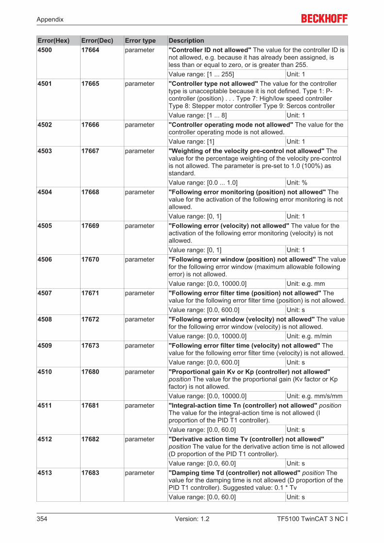
Appendix
TF5100 TwinCAT 3 NC I354 Version: 1.2
Error(Hex) Error(Dec) Error type Description4500 17664 parameter "Controller ID not allowed" The value for the controller ID is
not allowed, e.g. because it has already been assigned, isless than or equal to zero, or is greater than 255.Value range: [1 ... 255] Unit: 1
4501 17665 parameter "Controller type not allowed" The value for the controllertype is unacceptable because it is not defined. Type 1: P-controller (position) . . . Type 7: High/low speed controllerType 8: Stepper motor controller Type 9: Sercos controllerValue range: [1 ... 8] Unit: 1
4502 17666 parameter "Controller operating mode not allowed" The value for thecontroller operating mode is not allowed.Value range: [1] Unit: 1
4503 17667 parameter "Weighting of the velocity pre-control not allowed" Thevalue for the percentage weighting of the velocity pre-controlis not allowed. The parameter is pre-set to 1.0 (100%) asstandard.Value range: [0.0 ... 1.0] Unit: %
4504 17668 parameter "Following error monitoring (position) not allowed" Thevalue for the activation of the following error monitoring is notallowed.Value range: [0, 1] Unit: 1
4505 17669 parameter "Following error (velocity) not allowed" The value for theactivation of the following error monitoring (velocity) is notallowed.Value range: [0, 1] Unit: 1
4506 17670 parameter "Following error window (position) not allowed" The valuefor the following error window (maximum allowable followingerror) is not allowed.Value range: [0.0, 10000.0] Unit: e.g. mm
4507 17671 parameter "Following error filter time (position) not allowed" Thevalue for the following error filter time (position) is not allowed.Value range: [0.0, 600.0] Unit: s
4508 17672 parameter "Following error window (velocity) not allowed" The valuefor the following error window (velocity) is not allowed.Value range: [0.0, 10000.0] Unit: e.g. m/min
4509 17673 parameter "Following error filter time (velocity) not allowed" Thevalue for the following error filter time (velocity) is not allowed.Value range: [0.0, 600.0] Unit: s
4510 17680 parameter "Proportional gain Kv or Kp (controller) not allowed"position The value for the proportional gain (Kv factor or Kpfactor) is not allowed.Value range: [0.0, 10000.0] Unit: e.g. mm/s/mm
4511 17681 parameter "Integral-action time Tn (controller) not allowed" positionThe value for the integral-action time is not allowed (Iproportion of the PID T1 controller).Value range: [0.0, 60.0] Unit: s
4512 17682 parameter "Derivative action time Tv (controller) not allowed"position The value for the derivative action time is not allowed(D proportion of the PID T1 controller).Value range: [0.0, 60.0] Unit: s
4513 17683 parameter "Damping time Td (controller) not allowed" position Thevalue for the damping time is not allowed (D proportion of thePID T1 controller). Suggested value: 0.1 * TvValue range: [0.0, 60.0] Unit: s
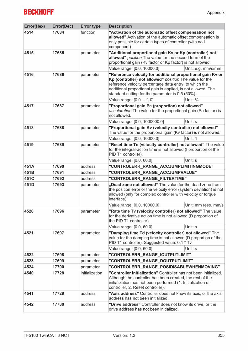
Appendix
TF5100 TwinCAT 3 NC I 355Version: 1.2
Error(Hex) Error(Dec) Error type Description4514 17684 function "Activation of the automatic offset compensation not
allowed" Activation of the automatic offset compensation isonly possible for certain types of controller (with no Icomponent).
4515 17685 parameter "Additional proportional gain Kv or Kp (controller) notallowed" position The value for the second term of theproportional gain (Kv factor or Kp factor) is not allowed.Value range: [0.0, 10000.0] Unit: e.g. mm/s/mm
4516 17686 parameter "Reference velocity for additional proportional gain Kv orKp (controller) not allowed" position The value for thereference velocity percentage data entry, to which theadditional proportional gain is applied, is not allowed. Thestandard setting for the parameter is 0.5 (50%).Value range: [0.0 ... 1.0] Unit: %
4517 17687 parameter "Proportional gain Pa (proportion) not allowed"acceleration The value for the proportional gain (Pa factor) isnot allowed.Value range: [0.0, 1000000.0] Unit: s
4518 17688 parameter "Proportional gain Kv (velocity controller) not allowed"The value for the proportional gain (Kv factor) is not allowed.Value range: [0.0, 10000.0] Unit: 1
4519 17689 parameter “Reset time Tn (velocity controller) not allowed” The valuefor the integral-action time is not allowed (I proportion of thePID T1 controller).Value range: [0.0, 60.0] Unit: s
451A 17690 address "CONTROLERR_RANGE_ACCJUMPLIMITINGMODE"451B 17691 address "CONTROLERR_RANGE_ACCJUMPVALUE"451C 17692 address "CONTROLERR_RANGE_FILTERTIME"451D 17693 parameter „Dead zone not allowed“ The value for the dead zone from
the position error or the velocity error (system deviation) is notallowed (only for complex controller with velocity or torqueinterface).Value range: [0.0, 10000.0] Unit: mm resp. mm/s
4520 17696 parameter ”Rate time Tv (velocity controller) not allowed” The valuefor the derivative action time is not allowed (D proportion ofthe PID T1 controller).Value range: [0.0, 60.0] Unit: s
4521 17697 parameter "Damping time Td (velocity controller) not allowed" Thevalue for the damping time is not allowed (D proportion of thePID T1 controller). Suggested value: 0.1 * TvValue range: [0.0, 60.0] Unit: s
4522 17698 parameter "CONTROLERR_RANGE_IOUTPUTLIMIT"4523 17699 parameter "CONTROLERR_RANGE_DOUTPUTLIMIT"4524 17700 parameter "CONTROLERR_RANGE_POSIDISABLEWHENMOVING"4540 17728 initialization "Controller initialization" Controller has not been initialized.
Although the controller has been created, the rest of theinitialization has not been performed (1. Initialization ofcontroller, 2. Reset controller).
4541 17729 address "Axis address" Controller does not know its axis, or the axisaddress has not been initialized.
4542 17730 address "Drive address" Controller does not know its drive, or thedrive address has not been initialized.
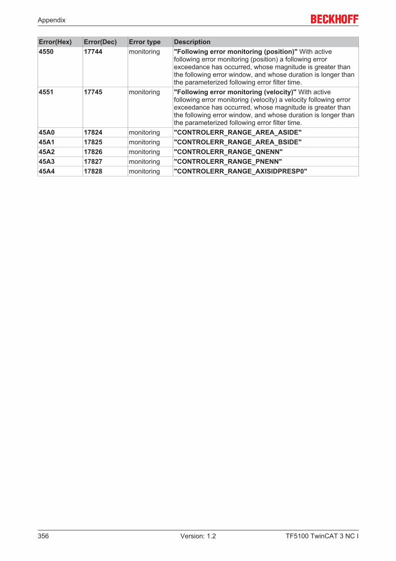
Appendix
TF5100 TwinCAT 3 NC I356 Version: 1.2
Error(Hex) Error(Dec) Error type Description4550 17744 monitoring "Following error monitoring (position)" With active
following error monitoring (position) a following errorexceedance has occurred, whose magnitude is greater thanthe following error window, and whose duration is longer thanthe parameterized following error filter time.
4551 17745 monitoring "Following error monitoring (velocity)" With activefollowing error monitoring (velocity) a velocity following errorexceedance has occurred, whose magnitude is greater thanthe following error window, and whose duration is longer thanthe parameterized following error filter time.
45A0 17824 monitoring "CONTROLERR_RANGE_AREA_ASIDE"45A1 17825 monitoring "CONTROLERR_RANGE_AREA_BSIDE"45A2 17826 monitoring "CONTROLERR_RANGE_QNENN"45A3 17827 monitoring "CONTROLERR_RANGE_PNENN"45A4 17828 monitoring "CONTROLERR_RANGE_AXISIDPRESP0"
Appendix
TF5100 TwinCAT 3 NC I 357Version: 1.2
7.7.7 Drive Errors

Appendix
TF5100 TwinCAT 3 NC I358 Version: 1.2
Error(hex) Error(dec) Error type Description4600 17920 Parameter ‘"Drive ID not allowed" The value for the drive ID is not
allowed, e.g. because it has already been assigned, is lessthan or equal to zero, or is greater than 255.Value range: [1 ... 255] Unit: 1
4601 17921 Parameter ‘Drive type impermissible’ The value for the drive type isimpermissible, since it is not defined.Value range: [1, 20] Unit: 1
4602 17922 Parameter ‘Drive operating mode impermissible’ The value for thedrive operating mode is impermissible (mode 1: standard).Value range: [1] Unit: 1
4603 17923 Parameter "Motor polarity inverted?" The flag for the motor polarityis not allowed. Flag 0: Positive motor polarity flag 1:Negative motor polarityValue range: [0, 1] Unit: 1
4604 17924 Parameter ‘Drift compensation/speed offset (DAC offset)’ The valuefor the drift compensation (DAC offset) is impermissible.Value range: [-100.0, 100.0] Unit: e.g. m/min
4605 17925 Parameter ‘Reference speed (velocity pre-control)’ The value for thereference speed (also called velocity pilot control) isimpermissible.Value range: [0.0, 10000.0] Unit: e.g. m/min
4606 17926 Parameter ‘Reference output in percent’ The value for the referenceoutput in percent is impermissible. The value 1.0 (100 %)usually corresponds to a voltage of 10.0 V.Value range: [0.0, 5.0] Unit: %
4607 17927 Parameter ‘Quadrant compensation factor’ The value for thequadrant compensation factor is impermissible.Value range: [0.0, 100.0] Unit: 1
4608 17928 Parameter ‘Velocity reference point’ The value for the velocityreference point in percent is impermissible. The value 1.0corresponds to 100 percent.Value range: [0.01, 1.0] Unit: %
4609 17929 Parameter ‘Output reference point’ The value for the outputreference point in percent is impermissible. The value 1.0corresponds to 100 percent.Value range: [0.01, 1.0] Unit: %
460A 17930 Parameter ‘Minimum or maximum output limits (output limitation)’The value for the minimum and/or maximum output limit isimpermissible. This will happen if the range of values isexceeded, the maximum limit is smaller than the minimumlimit, or the distance between the minimum and maximumlimits is zero. The minimum limit is initially set to –1.0 (-100percent) and the maximum limit to 1.0 (100 percent).Value range: [-1.0, 1.0] Unit: %
460B 17931 Parameter “DRIVEERR_RANGE_MAXINCREMENT”460C 17932 Parameter “DRIVEERR_RANGE_ DRIVECONTROLDWORD”460D 17933 Parameter “DRIVEERR_RANGE_ RESETCYCLECOUNTER”460F 17935 Parameter ‘Drive torque output scaling impermissible’ The value is
impermissible as drive torque output scaling (rotary motor)or as force output scaling (linear motor).Value range: [0, 1000000] Unit: 1
4610 17936 Parameter „Drive velocity output scaling is not allowed“ The valuefor the drive velocity output scaling is not allowed.Value range: [0, 1000000] Unit: 1

Appendix
TF5100 TwinCAT 3 NC I 359Version: 1.2
Error(hex) Error(dec) Error type Description4611 17937 Parameter ‘Profi Drive DSC proportional gain Kpc (controller)
impermissible’ Positions The value for the Profi Drive DSCposition control gain (Kpc factor) is impermissible.Value range: [0, 0xFFFFFF] Unit: 0.001 * 1/s
4612 17938 Parameter ‘Table ID is impermissible’ The value for the table ID isimpermissible.Value range: [0, 255] Unit: 1
4613 17939 Parameter ‘Table interpolation type is impermissible’ The value isimpermissible as the table interpolation type.Value range: 0 (LINEAR), 2 (SPLINE) Unit: 1
4614 17940 Parameter ‘Output offset in percent is impermissible’ The value isimpermissible as an output offset in percent (+/- 1.0).Value range: [-1.0, 1.0] Unit: %
4615 17941 Parameter ‘Profi Drive DSC scaling for calculation of“Xerr” (controller) impermissible’ Positions: the value isimpermissible as Profi Drive DSC scaling for the calculationof ‘Xerr’.Value range: [0, 1000000] Unit: 1
4616 17942 Parameter ‘Drive acceleration output scaling impermissible’ Thevalue is impermissible as drive acceleration/decelerationoutput scaling.Value range: [0, 1000000] Unit: 1
4617 17943 Parameter ‘Drive position output scaling impermissible’ The valueis impermissible as drive position output scaling.Value range: [0, 1000000] Unit: 1
461C 17948 Parameter ‘Drive filter type impermissible for command variablefilter for the output position’ The value is impermissibleas a drive filter type for the smoothing of the output position(command variable filter for the setpoint position).Value range: [0, 2] Unit: 1
461D 17949 Parameter ‘Drive filter time impermissible for command variablefilter for the output position’ The value is impermissibleas a drive filter time for the smoothing of the output position(command variable filter for the setpoint position).Value range: [0.0, 1.0] Unit: s
461E 17950 Parameter ‘Drive filter order impermissible for command variablefilter for the output position’ The value is impermissibleas a drive filter order (P-Tn) for the smoothing of the outputposition (command variable filter for the setpoint position).Value range: [0, 10] Unit: 1
4620 17952 Parameter ‘Bit mask for stepper motor cycle impermissible’ Avalue of the different stepper motor masks is impermissiblefor the respective cycle.Value range: [0, 255] Unit: 1
4621 17953 Parameter ‘Bit mask for stepper motor holding currentimpermissible’ The value for the stepper motor holdingmask is impermissible.Value range: [0, 255] Unit: 1
4622 17954 Parameter ‘Scaling factor for actual torque (actual current)impermissible’ The value is impermissible as a scalingfactor for the actual torque (or actual current).Value range: [0, 1E+30] Unit:
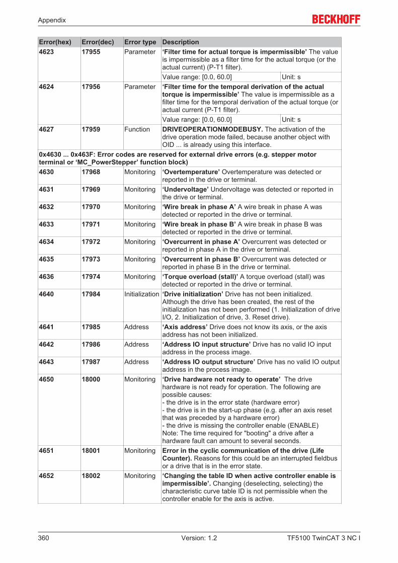
Appendix
TF5100 TwinCAT 3 NC I360 Version: 1.2
Error(hex) Error(dec) Error type Description4623 17955 Parameter ‘Filter time for actual torque is impermissible’ The value
is impermissible as a filter time for the actual torque (or theactual current) (P-T1 filter).Value range: [0.0, 60.0] Unit: s
4624 17956 Parameter ‘Filter time for the temporal derivation of the actualtorque is impermissible’ The value is impermissible as afilter time for the temporal derivation of the actual torque (oractual current (P-T1 filter).Value range: [0.0, 60.0] Unit: s
4627 17959 Function DRIVEOPERATIONMODEBUSY. The activation of thedrive operation mode failed, because another object withOID ... is already using this interface.
0x4630 ... 0x463F: Error codes are reserved for external drive errors (e.g. stepper motorterminal or ‘MC_PowerStepper’ function block)4630 17968 Monitoring ‘Overtemperature’ Overtemperature was detected or
reported in the drive or terminal.4631 17969 Monitoring ‘Undervoltage’ Undervoltage was detected or reported in
the drive or terminal.4632 17970 Monitoring ‘Wire break in phase A’ A wire break in phase A was
detected or reported in the drive or terminal.4633 17971 Monitoring ‘Wire break in phase B’ A wire break in phase B was
detected or reported in the drive or terminal.4634 17972 Monitoring ‘Overcurrent in phase A’ Overcurrent was detected or
reported in phase A in the drive or terminal.4635 17973 Monitoring ‘Overcurrent in phase B’ Overcurrent was detected or
reported in phase B in the drive or terminal.4636 17974 Monitoring ‘Torque overload (stall)’ A torque overload (stall) was
detected or reported in the drive or terminal.4640 17984 Initialization ‘Drive initialization’ Drive has not been initialized.
Although the drive has been created, the rest of theinitialization has not been performed (1. Initialization of driveI/O, 2. Initialization of drive, 3. Reset drive).
4641 17985 Address ‘Axis address’ Drive does not know its axis, or the axisaddress has not been initialized.
4642 17986 Address ‘Address IO input structure’ Drive has no valid IO inputaddress in the process image.
4643 17987 Address ‘Address IO output structure’ Drive has no valid IO outputaddress in the process image.
4650 18000 Monitoring ‘Drive hardware not ready to operate’ The drivehardware is not ready for operation. The following arepossible causes:- the drive is in the error state (hardware error)- the drive is in the start-up phase (e.g. after an axis resetthat was preceded by a hardware error)- the drive is missing the controller enable (ENABLE)Note: The time required for "booting" a drive after ahardware fault can amount to several seconds.
4651 18001 Monitoring Error in the cyclic communication of the drive (LifeCounter). Reasons for this could be an interrupted fieldbusor a drive that is in the error state.
4652 18002 Monitoring ‘Changing the table ID when active controller enable isimpermissible’. Changing (deselecting, selecting) thecharacteristic curve table ID is not permissible when thecontroller enable for the axis is active.
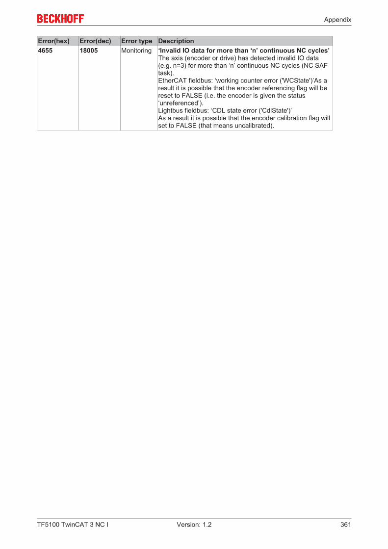
Appendix
TF5100 TwinCAT 3 NC I 361Version: 1.2
Error(hex) Error(dec) Error type Description4655 18005 Monitoring ‘Invalid IO data for more than ‘n’ continuous NC cycles’
The axis (encoder or drive) has detected invalid IO data(e.g. n=3) for more than ‘n’ continuous NC cycles (NC SAFtask).EtherCAT fieldbus: ‘working counter error ('WCState')’As aresult it is possible that the encoder referencing flag will bereset to FALSE (i.e. the encoder is given the status‘unreferenced’).Lightbus fieldbus: ‘CDL state error ('CdlState')’As a result it is possible that the encoder calibration flag willset to FALSE (that means uncalibrated).

Appendix
TF5100 TwinCAT 3 NC I362 Version: 1.2
7.7.8 Table Errors
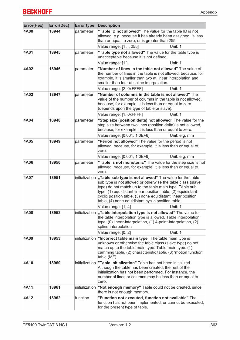
Appendix
TF5100 TwinCAT 3 NC I 363Version: 1.2
Error(Hex) Error(Dec) Error type Description4A00 18944 parameter "Table ID not allowed" The value for the table ID is not
allowed, e.g. because it has already been assigned, is lessthan or equal to zero, or is greater than 255.Value range: [1 ... 255] Unit: 1
4A01 18945 parameter "Table type not allowed" The value for the table type isunacceptable because it is not defined.Value range: [1 ] Unit: 1
4A02 18946 parameter "Number of lines in the table not allowed" The value ofthe number of lines in the table is not allowed, because, forexample, it is smaller than two at linear interpolation andsmaller than four at spline interpolation.Value range: [2, 0xFFFF] Unit: 1
4A03 18947 parameter "Number of columns in the table is not allowed" Thevalue of the number of columns in the table is not allowed,because, for example, it is less than or equal to zero(depends upon the type of table or slave).Value range: [1, 0xFFFF] Unit: 1
4A04 18948 parameter "Step size (position delta) not allowed" The value for thestep size between two lines (position delta) is not allowed,because, for example, it is less than or equal to zero.Value range: [0.001, 1.0E+6] Unit: e.g. mm
4A05 18949 parameter "Period not allowed" The value for the period is notallowed, because, for example, it is less than or equal tozero.Value range: [0.001, 1.0E+9] Unit: e.g. mm
4A06 18950 parameter "Table is not monotonic" The value for the step size is notallowed, because, for example, it is less than or equal tozero.
4A07 18951 initialization „Table sub type is not allowed“ The value for the tablesub type is not allowed or otherwise the table class (slavetype) do not match up to the table main type. Table subtype: (1) equidistant linear position table, (2) equidistantcyclic position table, (3) none equidistant linear positiontable, (4) none equidistant cyclic position tableValue range: [1, 4] Unit: 1
4A08 18952 initialization „Table interpolation type is not allowed“ The value forthe table interpolation type is allowed. Table interpolationtype: (0) linear-interpolation, (1) 4-point-interpolation, (2)spline-interpolationValue range: [0, 2] Unit: 1
4A09 18953 initialization "Incorrect table main type" The table main type isunknown or otherwise the table class (slave type) do notmatch up to the table main type. Table main type: (1)camming table, (2) characteristic table, (3) 'motion function'table (MF)
4A10 18960 initialization "Table initialization" Table has not been initialized.Although the table has been created, the rest of theinitialization has not been performed. For instance, thenumber of lines or columns may be less than or equal tozero.
4A11 18961 initialization "Not enough memory" Table could not be created, sincethere is not enough memory.
4A12 18962 function "Function not executed, function not available" Thefunction has not been implemented, or cannot be executed,for the present type of table.
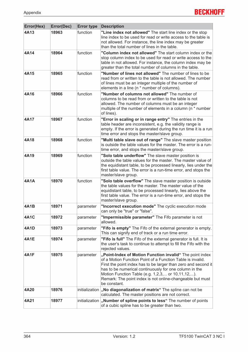
Appendix
TF5100 TwinCAT 3 NC I364 Version: 1.2
Error(Hex) Error(Dec) Error type Description4A13 18963 function "Line index not allowed" The start line index or the stop
line index to be used for read or write access to the table isnot allowed. For instance, the line index may be greaterthan the total number of lines in the table.
4A14 18964 function "Column index not allowed" The start column index or thestop column index to be used for read or write access to thetable in not allowed. For instance, the column index may begreater than the total number of columns in the table.
4A15 18965 function "Number of lines not allowed" The number of lines to beread from or written to the table is not allowed. The numberof lines must be an integer multiple of the number ofelements in a line (n * number of columns).
4A16 18966 function "Number of columns not allowed" The number ofcolumns to be read from or written to the table is notallowed. The number of columns must be an integermultiple of the number of elements in a column (n * numberof lines).
4A17 18967 function "Error in scaling or in range entry" The entries in thetable header are inconsistent, e.g. the validity range isempty. If the error is generated during the run time it is a runtime error and stops the master/slave group.
4A18 18968 function "Multi table slave out of range" The slave master positionis outside the table values for the master. The error is a run-time error, and stops the master/slave group.
4A19 18969 function "Solo table underflow" The slave master position isoutside the table values for the master. The master value ofthe equidistant table, to be processed linearly, lies under thefirst table value. The error is a run-time error, and stops themaster/slave group.
4A1A 18970 function "Solo table overflow" The slave master position is outsidethe table values for the master. The master value of theequidistant table, to be processed linearly, lies above thefirst table value. The error is a run-time error, and stops themaster/slave group.
4A1B 18971 parameter "Incorrect execution mode" The cyclic execution modecan only be "true" or "false".
4A1C 18972 parameter "Impermissible parameter" The Fifo parameter is notallowed.
4A1D 18973 parameter "Fifo is empty" The Fifo of the external generator is empty.This can signify end of track or a run time error.
4A1E 18974 parameter "Fifo is full" The Fifo of the external generator is full. It isthe user‘s task to continue to attempt to fill the Fifo with therejected values.
4A1F 18975 parameter „Point-Index of Motion Function invalid“ The point indexof a Motion Function Point of a Function Table is invalid.First the point index has to be larger than zero and second ithas to be numerical continuously for one column in theMotion Function Table (e.g. 1,2,3,... or 10,11,12,...).Remark: The point index is not online-changeable but mustbe constant.
4A20 18976 initialization „No diagonalization of matrix“ The spline can not becalculated. The master positions are not correct.
4A21 18977 initialization „Number of spline points to less“ The number of pointsof a cubic spline has to be greater than two.
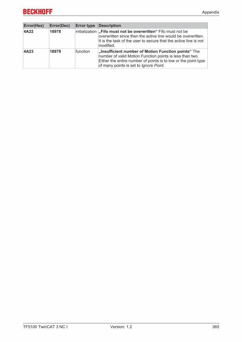
Appendix
TF5100 TwinCAT 3 NC I 365Version: 1.2
Error(Hex) Error(Dec) Error type Description4A22 18978 initialization „Fifo must not be overwritten“ Fifo must not be
overwritten since then the active line would be overwritten.It is the task of the user to secure that the active line is notmodified.
4A23 18979 function „Insufficient number of Motion Function points“ Thenumber of valid Motion Function points is less than two.Either the entire number of points is to low or the point typeof many points is set to Ignore Point.

Appendix
TF5100 TwinCAT 3 NC I366 Version: 1.2
7.7.9 NC-PLC Errors
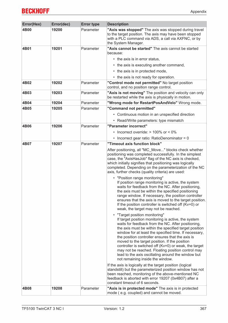
Appendix
TF5100 TwinCAT 3 NC I 367Version: 1.2
Error(Hex) Error(dec) Error type Description4B00 19200 Parameter "Axis was stopped" The axis was stopped during travel
to the target position. The axis may have been stoppedwith a PLC command via ADS, a call via AXFNC, or bythe System Manager.
4B01 19201 Parameter "Axis cannot be started" The axis cannot be startedbecause:
• the axis is in error status,• the axis is executing another command,• the axis is in protected mode,• the axis is not ready for operation.
4B02 19202 Parameter "Control mode not permitted" No target positioncontrol, and no position range control.
4B03 19203 Parameter "Axis is not moving" The position and velocity can onlybe restarted while the axis is physically in motion.
4B04 19204 Parameter "Wrong mode for RestartPosAndVelo" Wrong mode.4B05 19205 Parameter "Command not permitted"
• Continuous motion in an unspecified direction• Read/Write parameters: type mismatch
4B06 19206 Parameter "Parameter incorrect"• Incorrect override: > 100% or < 0%• Incorrect gear ratio: RatioDenominator = 0
4B07 19207 Parameter "Timeout axis function block"After positioning, all "MC_Move..." blocks check whetherpositioning was completed successfully. In the simplestcase, the "AxisHasJob" flag of the NC axis is checked,which initially signifies that positioning was logicallycompleted. Depending on the parameterization of the NCaxis, further checks (quality criteria) are used:
• "Position range monitoring"If position range monitoring is active, the systemwaits for feedback from the NC. After positioning,the axis must be within the specified positioningrange window. If necessary, the position controllerensures that the axis is moved to the target position.If the position controller is switched off (Kv=0) orweak, the target may not be reached.
• "Target position monitoring"If target position monitoring is active, the systemwaits for feedback from the NC. After positioning,the axis must be within the specified target positionwindow for at least the specified time. If necessary,the position controller ensures that the axis ismoved to the target position. If the positioncontroller is switched off (Kv=0) or weak, the targetmay not be reached. Floating position control maylead to the axis oscillating around the window butnot remaining inside the window.
If the axis is logically at the target position (logicalstandstill) but the parameterized position window has notbeen reached, monitoring of the above-mentioned NCfeedback is aborted with error 19207 (0x4B07) after aconstant timeout of 6 seconds.
4B08 19208 Parameter "Axis is in protected mode" The axis is in protectedmode ( e.g. coupled) and cannot be moved.
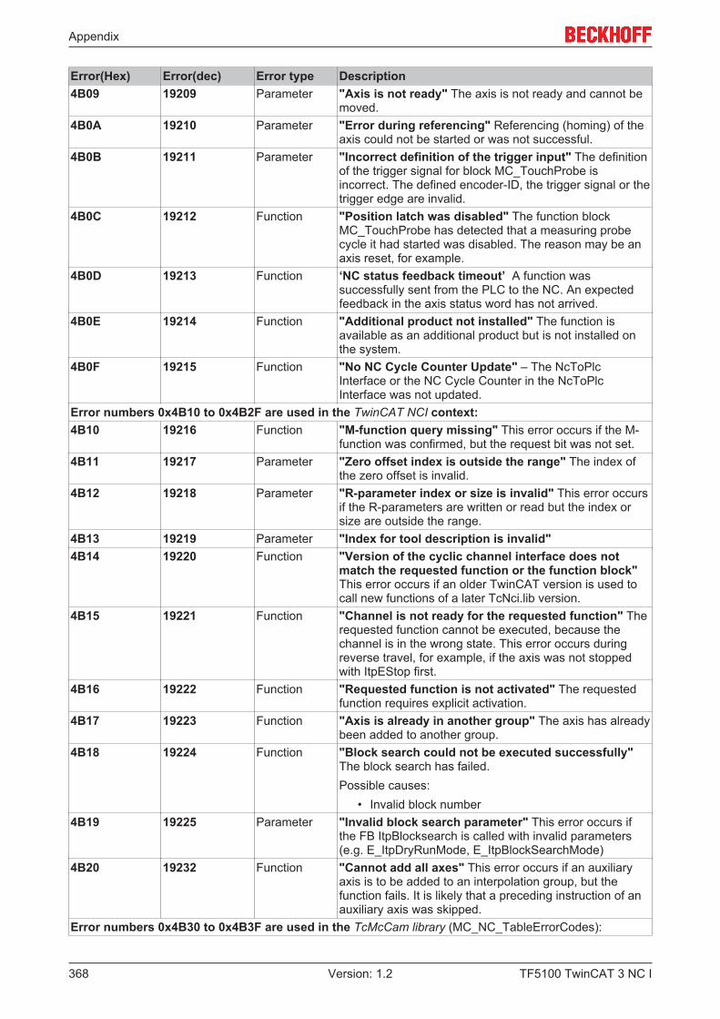
Appendix
TF5100 TwinCAT 3 NC I368 Version: 1.2
Error(Hex) Error(dec) Error type Description4B09 19209 Parameter "Axis is not ready" The axis is not ready and cannot be
moved.4B0A 19210 Parameter "Error during referencing" Referencing (homing) of the
axis could not be started or was not successful.4B0B 19211 Parameter "Incorrect definition of the trigger input" The definition
of the trigger signal for block MC_TouchProbe isincorrect. The defined encoder-ID, the trigger signal or thetrigger edge are invalid.
4B0C 19212 Function "Position latch was disabled" The function blockMC_TouchProbe has detected that a measuring probecycle it had started was disabled. The reason may be anaxis reset, for example.
4B0D 19213 Function ‘NC status feedback timeout’ A function wassuccessfully sent from the PLC to the NC. An expectedfeedback in the axis status word has not arrived.
4B0E 19214 Function "Additional product not installed" The function isavailable as an additional product but is not installed onthe system.
4B0F 19215 Function "No NC Cycle Counter Update" – The NcToPlcInterface or the NC Cycle Counter in the NcToPlcInterface was not updated.
Error numbers 0x4B10 to 0x4B2F are used in the TwinCAT NCI context:4B10 19216 Function "M-function query missing" This error occurs if the M-
function was confirmed, but the request bit was not set.4B11 19217 Parameter "Zero offset index is outside the range" The index of
the zero offset is invalid.4B12 19218 Parameter "R-parameter index or size is invalid" This error occurs
if the R-parameters are written or read but the index orsize are outside the range.
4B13 19219 Parameter "Index for tool description is invalid"4B14 19220 Function "Version of the cyclic channel interface does not
match the requested function or the function block"This error occurs if an older TwinCAT version is used tocall new functions of a later TcNci.lib version.
4B15 19221 Function "Channel is not ready for the requested function" Therequested function cannot be executed, because thechannel is in the wrong state. This error occurs duringreverse travel, for example, if the axis was not stoppedwith ItpEStop first.
4B16 19222 Function "Requested function is not activated" The requestedfunction requires explicit activation.
4B17 19223 Function "Axis is already in another group" The axis has alreadybeen added to another group.
4B18 19224 Function "Block search could not be executed successfully"The block search has failed.Possible causes:
• Invalid block number4B19 19225 Parameter "Invalid block search parameter" This error occurs if
the FB ItpBlocksearch is called with invalid parameters(e.g. E_ItpDryRunMode, E_ItpBlockSearchMode)
4B20 19232 Function "Cannot add all axes" This error occurs if an auxiliaryaxis is to be added to an interpolation group, but thefunction fails. It is likely that a preceding instruction of anauxiliary axis was skipped.
Error numbers 0x4B30 to 0x4B3F are used in the TcMcCam library (MC_NC_TableErrorCodes):
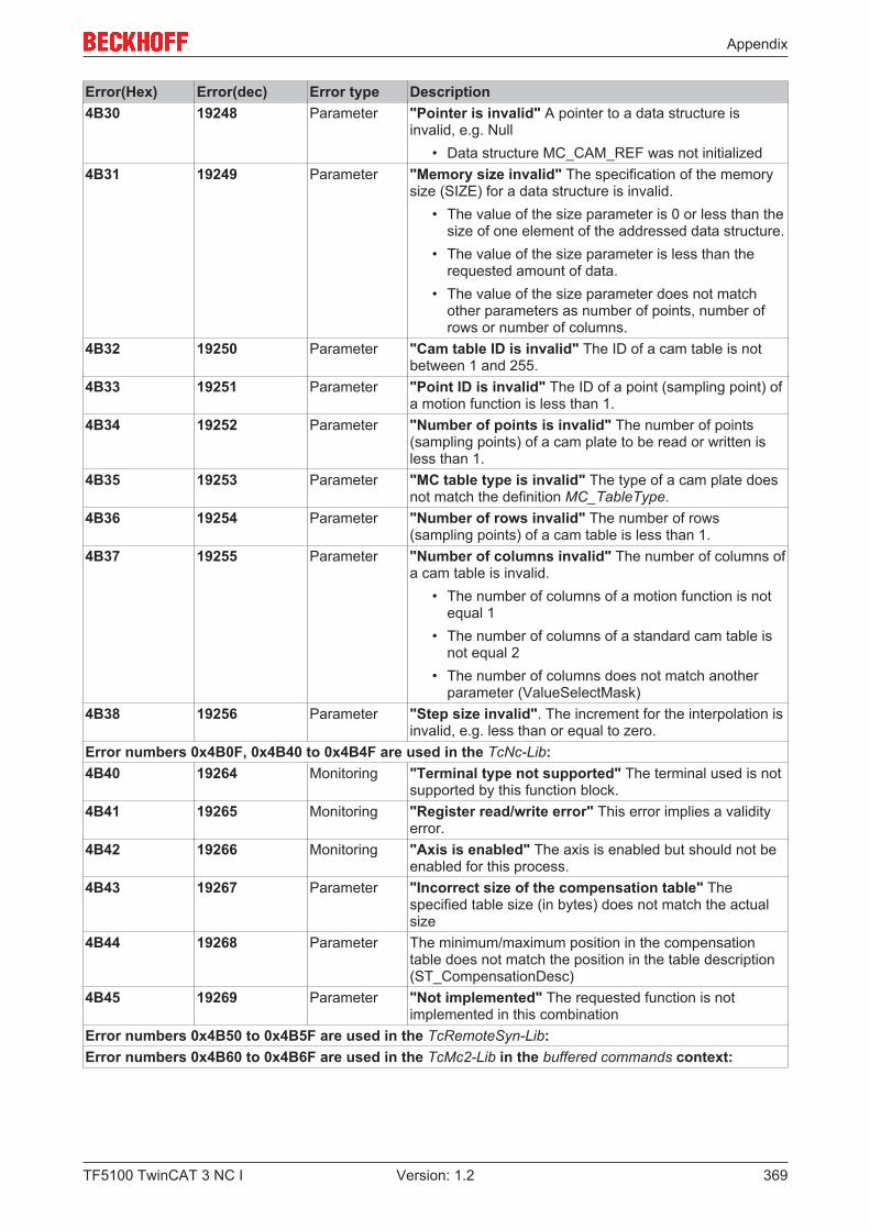
Appendix
TF5100 TwinCAT 3 NC I 369Version: 1.2
Error(Hex) Error(dec) Error type Description4B30 19248 Parameter "Pointer is invalid" A pointer to a data structure is
invalid, e.g. Null• Data structure MC_CAM_REF was not initialized
4B31 19249 Parameter "Memory size invalid" The specification of the memorysize (SIZE) for a data structure is invalid.
• The value of the size parameter is 0 or less than thesize of one element of the addressed data structure.
• The value of the size parameter is less than therequested amount of data.
• The value of the size parameter does not matchother parameters as number of points, number ofrows or number of columns.
4B32 19250 Parameter "Cam table ID is invalid" The ID of a cam table is notbetween 1 and 255.
4B33 19251 Parameter "Point ID is invalid" The ID of a point (sampling point) ofa motion function is less than 1.
4B34 19252 Parameter "Number of points is invalid" The number of points(sampling points) of a cam plate to be read or written isless than 1.
4B35 19253 Parameter "MC table type is invalid" The type of a cam plate doesnot match the definition MC_TableType.
4B36 19254 Parameter "Number of rows invalid" The number of rows(sampling points) of a cam table is less than 1.
4B37 19255 Parameter "Number of columns invalid" The number of columns ofa cam table is invalid.
• The number of columns of a motion function is notequal 1
• The number of columns of a standard cam table isnot equal 2
• The number of columns does not match anotherparameter (ValueSelectMask)
4B38 19256 Parameter "Step size invalid". The increment for the interpolation isinvalid, e.g. less than or equal to zero.
Error numbers 0x4B0F, 0x4B40 to 0x4B4F are used in the TcNc-Lib:4B40 19264 Monitoring "Terminal type not supported" The terminal used is not
supported by this function block.4B41 19265 Monitoring "Register read/write error" This error implies a validity
error.4B42 19266 Monitoring "Axis is enabled" The axis is enabled but should not be
enabled for this process.4B43 19267 Parameter "Incorrect size of the compensation table" The
specified table size (in bytes) does not match the actualsize
4B44 19268 Parameter The minimum/maximum position in the compensationtable does not match the position in the table description(ST_CompensationDesc)
4B45 19269 Parameter "Not implemented" The requested function is notimplemented in this combination
Error numbers 0x4B50 to 0x4B5F are used in the TcRemoteSyn-Lib:Error numbers 0x4B60 to 0x4B6F are used in the TcMc2-Lib in the buffered commands context:
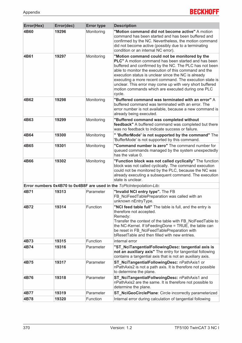
Appendix
TF5100 TwinCAT 3 NC I370 Version: 1.2
Error(Hex) Error(dec) Error type Description4B60 19296 Monitoring "Motion command did not become active" A motion
command has been started and has been buffered andconfirmed by the NC. Nevertheless, the motion commanddid not become active (possibly due to a terminatingcondition or an internal NC error).
4B61 19297 Monitoring "Motion command could not be monitored by thePLC" A motion command has been started and has beenbuffered and confirmed by the NC. The PLC has not beenable to monitor the execution of this command and theexecution status is unclear since the NC is alreadyexecuting a more recent command. The execution state isunclear. This error may come up with very short bufferedmotion commands which are executed during one PLCcycle.
4B62 19298 Monitoring "Buffered command was terminated with an error" Abuffered command was terminated with an error. Theerror number is not available, because a new command isalready being executed.
4B63 19299 Monitoring "Buffered command was completed withoutfeedback" A buffered command was completed but therewas no feedback to indicate success or failure.
4B64 19300 Monitoring " 'BufferMode' is not supported by the command" The'BufferMode' is not supported by this command.
4B65 19301 Monitoring "Command number is zero" The command number forqueued commands managed by the system unexpectedlyhas the value 0.
4B66 19302 Monitoring "Function block was not called cyclically" The functionblock was not called cyclically. The command executioncould not be monitored by the PLC, because the NC wasalready executing a subsequent command. The executionstate is unclear.
Error numbers 0x4B70 to 0x4B8F are used in the TcPlcInterpolation-Lib:4B71 19313 Parameter "Invalid NCI entry type". The FB
FB_NciFeedTablePreparation was called with anunknown nEntryType.
4B72 19314 Function "NCI feed table full" The table is full, and the entry istherefore not accepted.Remedy:Transfer the context of the table with FB_NciFeedTable tothe NC-Kernel. If bFeedingDone = TRUE, the table canbe reset in FB_NciFeedTablePreparation withbResetTable and then filled with new entries.
4B73 19315 Function internal error4B74 19316 Parameter "ST_NciTangentialFollowingDesc: tangential axis is
not an auxiliary axis" The entry for tangential followingcontains a tangential axis that is not an auxiliary axis.
4B75 19317 Parameter ST_NciTangentialFollowingDesc: nPathAxis1 ornPathAxis2 is not a path axis. It is therefore not possibleto determine the plane.
4B76 19318 Parameter ST_NciTangentialFollwoingDesc: nPathAxis1 andnPathAxis2 are the same. It is therefore not possible todetermine the plane.
4B77 19319 Parameter ST_NciGeoCirclePlane: Circle incorrectly parameterized4B78 19320 Function Internal error during calculation of tangential following
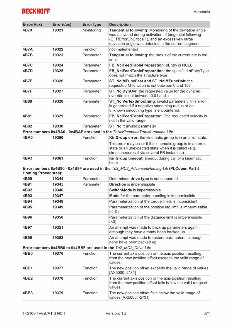
Appendix
TF5100 TwinCAT 3 NC I 371Version: 1.2
Error(Hex) Error(dec) Error type Description4B79 19321 Monitoring Tangential following: Monitoring of the deviation angle
was activated during activation of tangential following(E_TfErrorOnCritical1), and an excessively largedeviation angle was detected in the current segment.
4B7A 19322 Function not implemented4B7B 19323 Parameter Tangential following: the radius of the current arc is too
small4B7C 19324 Parameter FB_NciFeedTablePreparation: pEntry is NULL4B7D 19325 Parameter FB_NciFeedTablePreparation: the specified nEntryType
does not match the structure type4B7E 19326 Parameter ST_NciMFuncFast and ST_NciMFuncHsk: the
requested M-function is not between 0 and 1594B7F 19327 Parameter ST_NciDynOvr: the requested value for the dynamic
override is not between 0.01 and 14B80 19328 Parameter ST_NciVertexSmoothing: invalid parameter. This error
is generated if a negative smoothing radius or anunknown smoothing type is encountered.
4B81 19329 Parameter FB_NciFeedTablePrepartion: The requested velocity isnot in the valid range
4B82 19330 Parameter ST_Nci*: invalid parameterError numbers 0x4BA0 - 0x4BAF are used in the TcNcKinematicTransformation-Lib:4BA0 19360 Function KinGroup error: the kinematic group is in an error state.
This error may occur if the kinematic group is in an errorstate or an unexpected state when it is called (e.g.simultaneous call via several FB instances).
4BA1 19361 Function KinGroup timeout: timeout during call of a kinematicblock
Error numbers 0x4B90 - 0x4B9F are used in the Tc3_MC2_AdvancedHoming-Lib (PLCopen Part 5:Homing Procedures):4B90 19344 Parameter Determined drive type is not supported4B91 19345 Parameter Direction is impermissible4B92 19346 SwitchMode is impermissible4B93 19347 Mode for the parameter handling is impermissible4B94 19348 Parameterization of the torque limits is inconsistent4B95 19349 Parameterization of the position lag limit is impermissible
(<=0).4B96 19350 Parameterization of the distance limit is impermissible
(<0)4B97 19351 An attempt was made to back up parameters again,
although they have already been backed up.4B98 19352 An attempt was made to restore parameters, although
none have been backed up.Error numbers 0x4BB0 to 0x4BBF are used in the Tc2_MC2_Drive-Lib:4BB0 19376 Function The current axis position or the axis position resulting
from the new position offset exceeds the valid range ofvalues.
4BB1 19377 Function The new position offset exceeds the valid range of values[AX5000: 2^31]
4BB2 19378 Function The current axis position or the axis position resultingfrom the new position offset falls below the valid range ofvalues.
4BB3 19379 Function The new position offset falls below the valid range ofvalues [AX5000: -2^31]
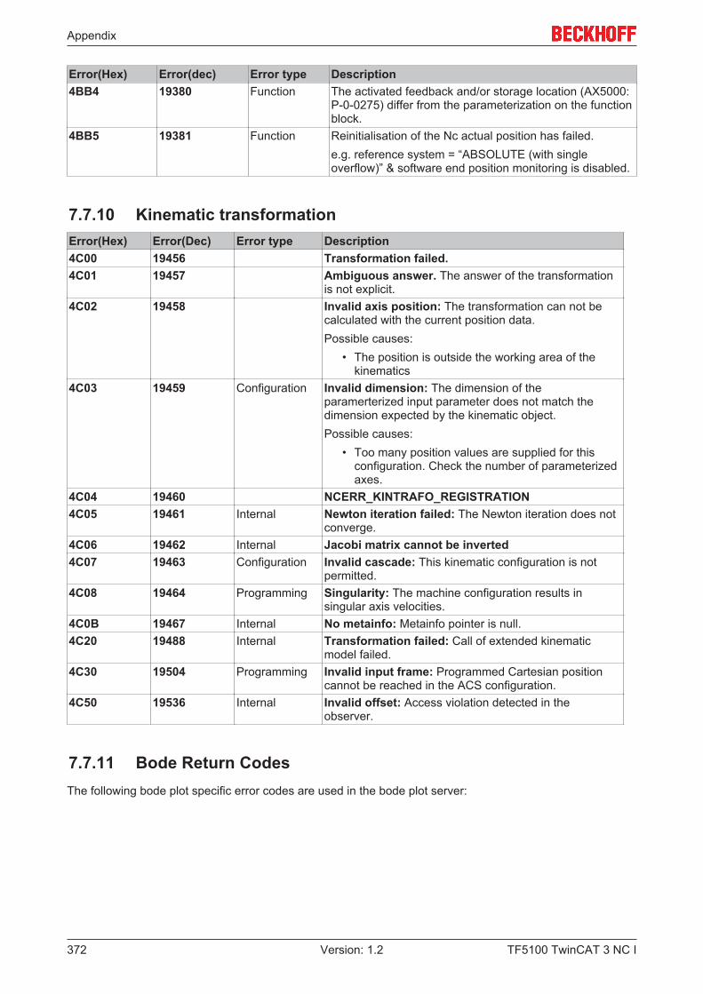
Appendix
TF5100 TwinCAT 3 NC I372 Version: 1.2
Error(Hex) Error(dec) Error type Description4BB4 19380 Function The activated feedback and/or storage location (AX5000:
P-0-0275) differ from the parameterization on the functionblock.
4BB5 19381 Function Reinitialisation of the Nc actual position has failed.e.g. reference system = “ABSOLUTE (with singleoverflow)” & software end position monitoring is disabled.
7.7.10 Kinematic transformationError(Hex) Error(Dec) Error type Description4C00 19456 Transformation failed.4C01 19457 Ambiguous answer. The answer of the transformation
is not explicit.4C02 19458 Invalid axis position: The transformation can not be
calculated with the current position data.Possible causes:
• The position is outside the working area of thekinematics
4C03 19459 Configuration Invalid dimension: The dimension of theparamerterized input parameter does not match thedimension expected by the kinematic object.Possible causes:
• Too many position values are supplied for thisconfiguration. Check the number of parameterizedaxes.
4C04 19460 NCERR_KINTRAFO_REGISTRATION4C05 19461 Internal Newton iteration failed: The Newton iteration does not
converge.4C06 19462 Internal Jacobi matrix cannot be inverted4C07 19463 Configuration Invalid cascade: This kinematic configuration is not
permitted.4C08 19464 Programming Singularity: The machine configuration results in
singular axis velocities.4C0B 19467 Internal No metainfo: Metainfo pointer is null.4C20 19488 Internal Transformation failed: Call of extended kinematic
model failed.4C30 19504 Programming Invalid input frame: Programmed Cartesian position
cannot be reached in the ACS configuration.4C50 19536 Internal Invalid offset: Access violation detected in the
observer.
7.7.11 Bode Return CodesThe following bode plot specific error codes are used in the bode plot server:
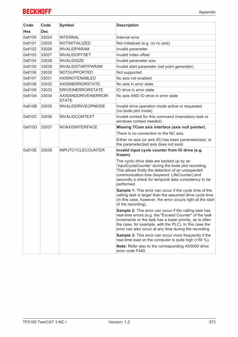
Appendix
TF5100 TwinCAT 3 NC I 373Version: 1.2
CodeHex
CodeDec
Symbol Description
0x8100 33024 INTERNAL Internal error0x8101 33025 NOTINITIALIZED Not initialized (e.g. no nc axis)0x8102 33026 INVALIDPARAM Invalid parameter0x8103 33027 INVALIDOFFSET Invalid index offset0x8104 33028 INVALIDSIZE Invalid parameter size0x8105 33029 INVALIDSTARTPARAM Invalid start parameter (set point generator)0x8106 33030 NOTSUPPORTED Not supported0x8107 33031 AXISNOTENABLED Nc axis not enabled0x8108 33032 AXISINERRORSTATE Nc axis in error state0x8109 33033 DRIVEINERRORSTATE IO drive in error state0x810A 33034 AXISANDDRIVEINERROR-
STATENc axis AND IO drive in error state
0x810B 33035 INVALIDDRIVEOPMODE Invalid drive operation mode active or requested (no bode plot mode)
0x810C 33036 INVALIDCONTEXT Invalid context for this command (mandatory task orwindows context needed)
0x810D 33037 NOAXISINTERFACE Missing TCom axis interface (axis null pointer).There is no connection to the NC axis.Either no axis (or axis ID) has been parameterized, orthe parameterized axis does not exist.
0x810E 33038 INPUTCYCLECOUNTER Invalid input cycle counter from IO drive (e.g.frozen).The cyclic drive data are backed up by an‘InputCycleCounter’ during the bode plot recording.This allows firstly the detection of an unexpectedcommunication loss (keyword: LifeCounter) andsecondly a check for temporal data consistency to beperformed.Sample 1: This error can occur if the cycle time of thecalling task is larger than the assumed drive cycle time(in this case, however, the error occurs right at the startof the recording).Sample 2: This error can occur if the calling task hasreal-time errors (e.g. the "Exceed Counter" of the taskincrements or the task has a lower priority, as is oftenthe case, for example, with the PLC). In this case theerror can also occur at any time during the recording.Sample 3: This error can occur more frequently if thereal-time load on the computer is quite high (>50 %).Note: Refer also to the corresponding AX5000 driveerror code F440.
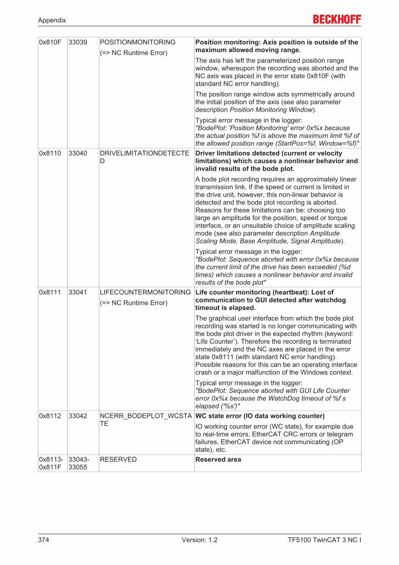
Appendix
TF5100 TwinCAT 3 NC I374 Version: 1.2
0x810F 33039 POSITIONMONITORING(=> NC Runtime Error)
Position monitoring: Axis position is outside of themaximum allowed moving range.The axis has left the parameterized position rangewindow, whereupon the recording was aborted and theNC axis was placed in the error state 0x810F (withstandard NC error handling).The position range window acts symmetrically aroundthe initial position of the axis (see also parameterdescription Position Monitoring Window).Typical error message in the logger:"BodePlot: 'Position Monitoring' error 0x%x becausethe actual position %f is above the maximum limit %f ofthe allowed position range (StartPos=%f, Window=%f)"
0x8110 33040 DRIVELIMITATIONDETECTED
Driver limitations detected (current or velocitylimitations) which causes a nonlinear behavior andinvalid results of the bode plot.A bode plot recording requires an approximately lineartransmission link. If the speed or current is limited inthe drive unit, however, this non-linear behavior isdetected and the bode plot recording is aborted.Reasons for these limitations can be: choosing toolarge an amplitude for the position, speed or torqueinterface, or an unsuitable choice of amplitude scalingmode (see also parameter description AmplitudeScaling Mode, Base Amplitude, Signal Amplitude).Typical error message in the logger:"BodePlot: Sequence aborted with error 0x%x becausethe current limit of the drive has been exceeded (%dtimes) which causes a nonlinear behavior and invalidresults of the bode plot"
0x8111 33041 LIFECOUNTERMONITORING(=> NC Runtime Error)
Life counter monitoring (heartbeat): Lost ofcommunication to GUI detected after watchdogtimeout is elapsed.The graphical user interface from which the bode plotrecording was started is no longer communicating withthe bode plot driver in the expected rhythm (keyword:‘Life Counter’). Therefore the recording is terminatedimmediately and the NC axes are placed in the errorstate 0x8111 (with standard NC error handling).Possible reasons for this can be an operating interfacecrash or a major malfunction of the Windows context.Typical error message in the logger:"BodePlot: Sequence aborted with GUI Life Countererror 0x%x because the WatchDog timeout of %f selapsed ('%s')"
0x8112 33042 NCERR_BODEPLOT_WCSTATE
WC state error (IO data working counter)IO working counter error (WC state), for example dueto real-time errors, EtherCAT CRC errors or telegramfailures, EtherCAT device not communicating (OPstate), etc.
0x8113-0x811F
33043-33055
RESERVED Reserved area
Appendix
TF5100 TwinCAT 3 NC I 375Version: 1.2
7.7.12 Further Error CodesTable 3:
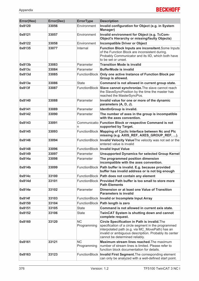
Appendix
TF5100 TwinCAT 3 NC I376 Version: 1.2
Error(Hex) Error(Dec) ErrorType Description0x8120 33056 Environment Invalid configuration for Object (e.g. in System
Manager)0x8121 33057 Environment Invalid environment for Object (e.g. TcCom-
Object's Hierarchy or missing/faulty Objects)0x8122 33058 Environment Incompatible Driver or Object0x8135 33077 Internal Function Block Inputs are inconsitent.Some Inputs
of the Function Block are inconsistent during.Probably Communicator and its IID, which both haveto be set or unset.
0x813b 33083 Parameter Transition Mode is invalid0x813c 33084 Parameter BufferMode is invalid0x813d 33085 FunctionBlock Only one active Instance of Function Block per
Group is allowed.0x813e 33086 State Command is not allowed in current group state.0x813f 33087 FunctionBlock Slave cannot synchronize.The slave cannot reach
the SlaveSyncPosition by the time the master hasreached the MasterSyncPos.
0x8140 33088 Parameter Invalid value for one or more of the dynamicparameters (A, D, J).
0x8141 33089 Parameter IdentInGroup is invalid.0x8142 33090 Parameter The number of axes in the group is incompatible
with the axes convention.0x8143 33091 Communicatio
nFunction Block or respective Command is notsupported by Target.
0x8145 33093 FunctionBlock Mapping of Cyclic Interface between Nc and Plcmissing (e.g. AXIS_REF, AXES_GROUP_REF, ...).
0x8146 33094 FunctionBlock Invalid Velocity ValueThe velocity was not set or theentered value is invalid
0x8148 33096 FunctionBlock Invalid Input Value0x8149 33097 Parameter Unsupported Dynamics for selected Group Kernel0x814a 33098 Parameter The programmed position dimension
incompatible with the axes convention.0x814b 33099 FunctionBlock Path buffer is invalid. E.g. because provided
buffer has invalid address or is not big enough0x814c 33100 FunctionBlock Path does not contain any element0x814d 33101 FunctionBlock Provided Path buffer is too small to store more
Path Elements0x814e 33102 Parameter Dimension or at least one Value of Transition
Parameters is invalid0x814f 33103 FunctionBlock Invalid or Incomplete Input Array0x8150 33104 FunctionBlock Path length is zero0x8151 33105 State Command is not allowed in current axis state.0x8152 33106 State TwinCAT System is shutting down and cannot
complete request.0x8160 33120 NC
ProgrammingCircle Specification in Path is invalid.Thespecification of a circle segment in the programmedinterpolated path (e.g. via MC_MovePath) has aninvalid or ambiguous descripition. Probably its centercannot be determined reliably.
0x8161 33121 NCProgramming
Maximum stream lines reached.The maximumnumber of stream lines is limited. Please refer tofunction block documentation for details.
0x8163 33123 FunctionBlock Invalid First Segment.The corresponding elementcan only be analyzed with a well-defined start point.
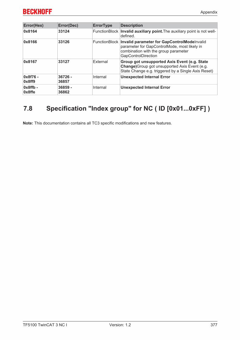
Appendix
TF5100 TwinCAT 3 NC I 377Version: 1.2
Error(Hex) Error(Dec) ErrorType Description0x8164 33124 FunctionBlock Invalid auxiliary point.The auxiliary point is not well-
defined.0x8166 33126 FunctionBlock Invalid parameter for GapControlModeInvalid
parameter for GapControlMode, most likely incombination with the group parameterGapControlDirection
0x8167 33127 External Group got unsupported Axis Event (e.g. StateChange)Group got unsupported Axis Event (e.g.State Change e.g. triggered by a Single Axis Reset)
0x8f76 - 0x8ff9
36726 - 36857
Internal Unexpected Internal Error
0x8ffb - 0x8ffe
36859 - 36862
Internal Unexpected Internal Error
7.8 Specification "Index group" for NC ( ID [0x01...0xFF] )
Note: This documentation contains all TC3 specific modifications and new features.
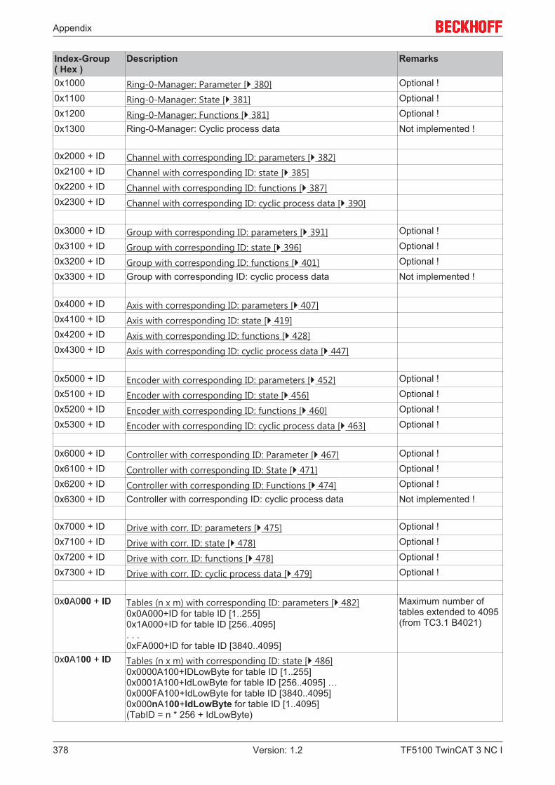
Appendix
TF5100 TwinCAT 3 NC I378 Version: 1.2
Index-Group ( Hex )
Description Remarks
0x1000 Ring-0-Manager: Parameter [} 380] Optional !0x1100 Ring-0-Manager: State [} 381] Optional !0x1200 Ring-0-Manager: Functions [} 381] Optional !0x1300 Ring-0-Manager: Cyclic process data Not implemented !
0x2000 + ID Channel with corresponding ID: parameters [} 382]0x2100 + ID Channel with corresponding ID: state [} 385]0x2200 + ID Channel with corresponding ID: functions [} 387]0x2300 + ID Channel with corresponding ID: cyclic process data [} 390]
0x3000 + ID Group with corresponding ID: parameters [} 391] Optional !0x3100 + ID Group with corresponding ID: state [} 396] Optional !0x3200 + ID Group with corresponding ID: functions [} 401] Optional !0x3300 + ID Group with corresponding ID: cyclic process data Not implemented !
0x4000 + ID Axis with corresponding ID: parameters [} 407]0x4100 + ID Axis with corresponding ID: state [} 419]0x4200 + ID Axis with corresponding ID: functions [} 428]0x4300 + ID Axis with corresponding ID: cyclic process data [} 447]
0x5000 + ID Encoder with corresponding ID: parameters [} 452] Optional !0x5100 + ID Encoder with corresponding ID: state [} 456] Optional !0x5200 + ID Encoder with corresponding ID: functions [} 460] Optional !0x5300 + ID Encoder with corresponding ID: cyclic process data [} 463] Optional !
0x6000 + ID Controller with corresponding ID: Parameter [} 467] Optional !0x6100 + ID Controller with corresponding ID: State [} 471] Optional !0x6200 + ID Controller with corresponding ID: Functions [} 474] Optional !0x6300 + ID Controller with corresponding ID: cyclic process data Not implemented !
0x7000 + ID Drive with corr. ID: parameters [} 475] Optional !0x7100 + ID Drive with corr. ID: state [} 478] Optional !0x7200 + ID Drive with corr. ID: functions [} 478] Optional !0x7300 + ID Drive with corr. ID: cyclic process data [} 479] Optional !
0x0A000 + ID Tables (n x m) with corresponding ID: parameters [} 482]0x0A000+ID for table ID [1..255]0x1A000+ID for table ID [256..4095]. . .0xFA000+ID for table ID [3840..4095]
Maximum number oftables extended to 4095(from TC3.1 B4021)
0x0A100 + ID Tables (n x m) with corresponding ID: state [} 486]0x0000A100+IDLowByte for table ID [1..255]0x0001A100+IdLowByte for table ID [256..4095] …0x000FA100+IdLowByte for table ID [3840..4095]0x000nA100+IdLowByte for table ID [1..4095](TabID = n * 256 + IdLowByte)
Appendix
TF5100 TwinCAT 3 NC I 379Version: 1.2
Index-Group ( Hex )
Description Remarks
0x0A200 + ID Tables (n x m) with corresponding ID: functions [} 487]0x0000A100+IDLowByte for table ID [1..255]0x0001A100+IdLowByte for table ID [256..4095] …0x000FA100+IdLowByte for table ID [3840..4095]0x000nA100+IdLowByte for table ID [1..4095](TabID = n * 256 + IdLowByte)
0x0A300 + ID Tables (n x m) with corresponding ID: cyclic process data0x0000A100+IDLowByte for table ID [1..255]0x0001A100+IdLowByte for table ID [256..4095] …0x000FA100+IdLowByte for table ID [3840..4095]0x000nA100+IdLowByte for table ID [1..4095](TabID = n * 256 + IdLowByte)
Not implemented !
0xF000 ...0xFFFF
reserved area (TwinCAT system area)
IndexGroup: IndexOffset:0xF081 0x00000000 ...
0xFFFFFFFF(n elements)
ADSIGRP_SUMUP_WRITEThe Read-Write-command contains a list inthe Write-data of multiple separate ADS-Write-commands (like a group request).Structure of the Write-Data:[ IdxGrp(1), IdxOff(1), WriteLen(1), ...,IdxGrp(n), IdxOff(n), WriteLen(n), WriteData(1), ..., WriteData(n) ]Structure of the Read-Data:[ Error(1), ..., Error(n) ]
0xF082 0x00000000 ...0xFFFFFFFF(n elements)
ADSIGRP_SUMUP_READWRITEThe Read-Write-command contains a list inthe Write-data of multiple separate ADS-Read-Write-commands (like a group request).Structure of the Write-Data:[ IdxGrp(1), IdxOff(1),ReadLen(1),WriteLen(1), ..., IdxGrp(n), IdxGrp(n),ReadLen(n), WriteLen(n),WriteData(1), ..., WriteData(n) ]Structure of the Read-Data:[ Error(1), ReadLen(1), ..., Error(n),ReadLen(n), ReadData(1), ..., ReadData(n) ]
0xF084 0x00000000 ...0xFFFFFFFF(n elements)
ADSIGRP_SUMUP_READ (READEX2)The Read-Write-command contains a list inthe Write-data of multiple separate ADS-Read-commands (like a group request).Structure of the Write-Data: [ IdxGrp(1), IdxOff(1), ReadLen(1), ...,IdxGrp(n), IdxGrp(n), ReadLen(n) ]Structure of the Read-Data: [ Error(1), ReadLen(1), ..., Error(n),ReadLen(n),ReadData(1), ..., ReadData(n) ]
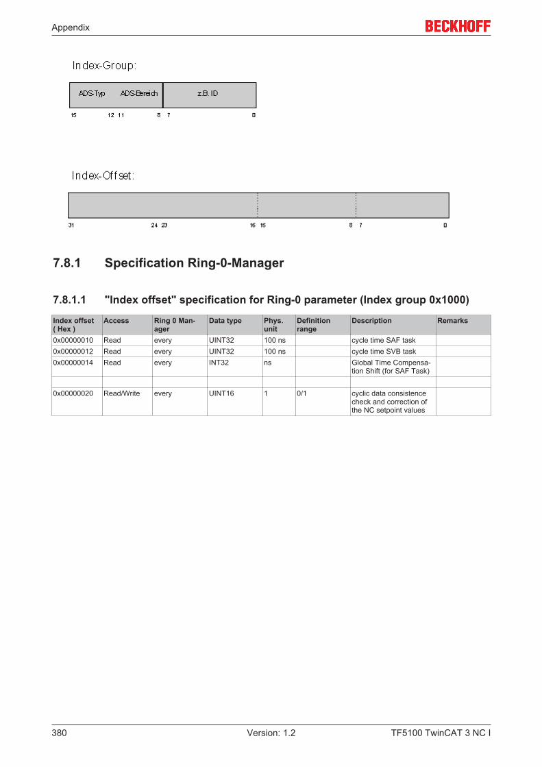
Appendix
TF5100 TwinCAT 3 NC I380 Version: 1.2
7.8.1 Specification Ring-0-Manager
7.8.1.1 "Index offset" specification for Ring-0 parameter (Index group 0x1000)
Index offset( Hex )
Access Ring 0 Man-ager
Data type Phys.unit
Definitionrange
Description Remarks
0x00000010 Read every UINT32 100 ns cycle time SAF task0x00000012 Read every UINT32 100 ns cycle time SVB task0x00000014 Read every INT32 ns Global Time Compensa-
tion Shift (for SAF Task)
0x00000020 Read/Write every UINT16 1 0/1 cyclic data consistencecheck and correction ofthe NC setpoint values
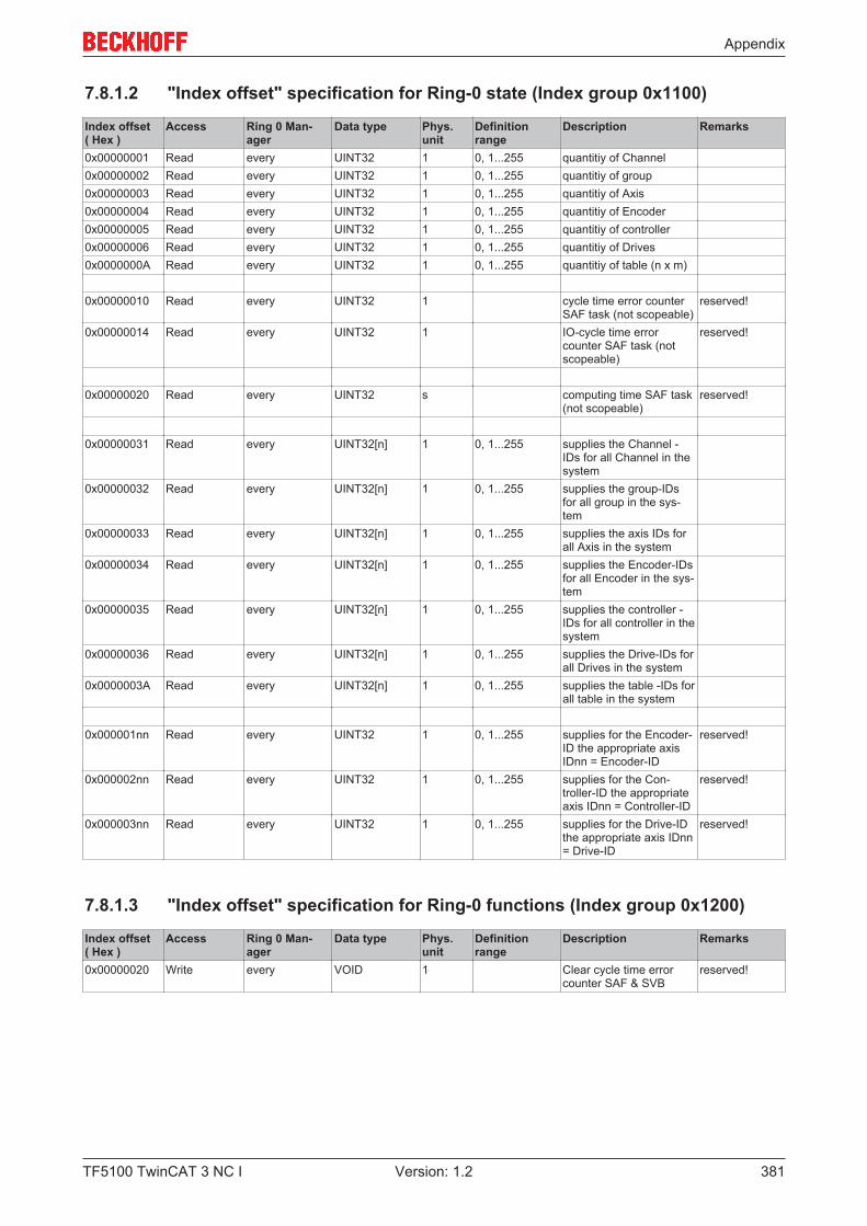
Appendix
TF5100 TwinCAT 3 NC I 381Version: 1.2
7.8.1.2 "Index offset" specification for Ring-0 state (Index group 0x1100)
Index offset( Hex )
Access Ring 0 Man-ager
Data type Phys.unit
Definitionrange
Description Remarks
0x00000001 Read every UINT32 1 0, 1...255 quantitiy of Channel0x00000002 Read every UINT32 1 0, 1...255 quantitiy of group0x00000003 Read every UINT32 1 0, 1...255 quantitiy of Axis0x00000004 Read every UINT32 1 0, 1...255 quantitiy of Encoder0x00000005 Read every UINT32 1 0, 1...255 quantitiy of controller0x00000006 Read every UINT32 1 0, 1...255 quantitiy of Drives0x0000000A Read every UINT32 1 0, 1...255 quantitiy of table (n x m)
0x00000010 Read every UINT32 1 cycle time error counterSAF task (not scopeable)
reserved!
0x00000014 Read every UINT32 1 IO-cycle time errorcounter SAF task (notscopeable)
reserved!
0x00000020 Read every UINT32 s computing time SAF task(not scopeable)
reserved!
0x00000031 Read every UINT32[n] 1 0, 1...255 supplies the Channel -IDs for all Channel in thesystem
0x00000032 Read every UINT32[n] 1 0, 1...255 supplies the group-IDsfor all group in the sys-tem
0x00000033 Read every UINT32[n] 1 0, 1...255 supplies the axis IDs forall Axis in the system
0x00000034 Read every UINT32[n] 1 0, 1...255 supplies the Encoder-IDsfor all Encoder in the sys-tem
0x00000035 Read every UINT32[n] 1 0, 1...255 supplies the controller -IDs for all controller in thesystem
0x00000036 Read every UINT32[n] 1 0, 1...255 supplies the Drive-IDs forall Drives in the system
0x0000003A Read every UINT32[n] 1 0, 1...255 supplies the table -IDs forall table in the system
0x000001nn Read every UINT32 1 0, 1...255 supplies for the Encoder-ID the appropriate axisIDnn = Encoder-ID
reserved!
0x000002nn Read every UINT32 1 0, 1...255 supplies for the Con-troller-ID the appropriateaxis IDnn = Controller-ID
reserved!
0x000003nn Read every UINT32 1 0, 1...255 supplies for the Drive-IDthe appropriate axis IDnn= Drive-ID
reserved!
7.8.1.3 "Index offset" specification for Ring-0 functions (Index group 0x1200)
Index offset( Hex )
Access Ring 0 Man-ager
Data type Phys.unit
Definitionrange
Description Remarks
0x00000020 Write every VOID 1 Clear cycle time errorcounter SAF & SVB
reserved!

Appendix
TF5100 TwinCAT 3 NC I382 Version: 1.2
7.8.2 Specification Channels
7.8.2.1 "Index offset" specification for Channel parameter (Index group 0x2000 +ID)

Appendix
TF5100 TwinCAT 3 NC I 383Version: 1.2
Index-Offset(Hex)
Access Channel type Data type Phys.unit
Definitionrange
Description Remarks
0x00000001 Read every UINT32 1 Channel ID0x00000002 Read every UINT8[30+1] 1 Channel name0x00000003 Read every UINT32 1 ENUM Channel type [} 487]0x00000004 Read every UINT32 1 ENUM Interpreter type
[} 487]0x00000005 Read every UINT32 1 program load buffer
size in bytes0x00000006 Read every UINT32 1 program no. according
to job list0x00000007 Read
/ Write
every UINT32 1 ENUM set load log mode[} 488]
0x00000008 Read
/ Write
every UINT32 1 ENUM set trace mode [} 488]
0x00000009 Read
/ Write
every UINT32 1 RESERVED
0x0000000A Read
/ Write
every UINT32 1 0/1 Records all feeder en-tries in a log filenamed "TcNci.log"
0x0000000B Read
/ Write
every UINT32 1 0/1 channel specific levelfor NC logger mes-sages0: errors only1: all NC messages
0x00000010 ReadWrite every Write{UINT32 1 0..159 Start index of M-func-
tionUINT32 1 1..160 number of M-functions
to be read}Read [n]{UINT8 1 0..159 Rule bit mask of the
M-functionINT32[10] 1 -1..159 Number of M-functions
to be cleared}
0x00000011 Write Interpolation Write M-function de-scription
Only used inter-nally!
0x00000012 Read
/ Write
Interpolation LREAL64 1 factor for G70
0x00000013 Read
/ Write
Interpolation LREAL64 1 Factor for G71
0x00000014 Write Interpolation { axes user symbols not yet releasedchar[32] user symbol (null-ter-
minated)char[10] system symbol (null-
terminated)}
0x00000015 Read
/ Write
Interpolation UINT16 resp.UINT32
1 0/1 default:FALSE
Activation of default G-code
NEW fromTC3.1 B4014
0x00000021 Read every UINT32 1 group ID (only explicitfor 3D and FIFO chan-nel)
0x00000031 Read
/ Write
Interpolation UINT16 1 Standard Output Portof the Interpreter
reserved func-tion,no standard!
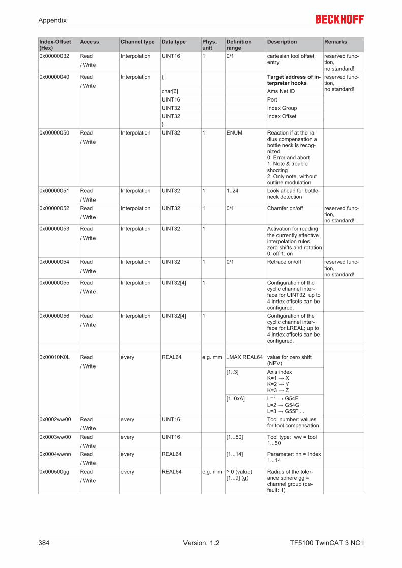
Appendix
TF5100 TwinCAT 3 NC I384 Version: 1.2
Index-Offset(Hex)
Access Channel type Data type Phys.unit
Definitionrange
Description Remarks
0x00000032 Read
/ Write
Interpolation UINT16 1 0/1 cartesian tool offsetentry
reserved func-tion,no standard!
0x00000040 Read
/ Write
Interpolation { Target address of in-terpreter hooks
reserved func-tion,no standard!char[6] Ams Net ID
UINT16 PortUINT32 Index GroupUINT32 Index Offset}
0x00000050 Read
/ Write
Interpolation UINT32 1 ENUM Reaction if at the ra-dius compensation abottle neck is recog-nized0: Error and abort1: Note & troubleshooting2: Only note, withoutoutline modulation
0x00000051 Read
/ Write
Interpolation UINT32 1 1..24 Look ahead for bottle-neck detection
0x00000052 Read
/ Write
Interpolation UINT32 1 0/1 Chamfer on/off reserved func-tion,no standard!
0x00000053 Read
/ Write
Interpolation UINT32 1 Activation for readingthe currently effectiveinterpolation rules,zero shifts and rotation0: off 1: on
0x00000054 Read
/ Write
Interpolation UINT32 1 0/1 Retrace on/off reserved func-tion,no standard!
0x00000055 Read
/ Write
Interpolation UINT32[4] 1 Configuration of thecyclic channel inter-face for UINT32; up to4 index offsets can beconfigured.
0x00000056 Read
/ Write
Interpolation UINT32[4] 1 Configuration of thecyclic channel inter-face for LREAL; up to4 index offsets can beconfigured.
0x00010K0L Read
/ Write
every REAL64 e.g. mm ±MAX REAL64 value for zero shift(NPV)
[1..3] Axis indexK=1 → XK=2 → YK=3 → Z
[1..0xA] L=1 → G54FL=2 → G54GL=3 → G55F ...
0x0002ww00 Read
/ Write
every UINT16 Tool number: valuesfor tool compensation
0x0003ww00 Read
/ Write
every UINT16 [1...50] Tool type: ww = tool1...50
0x0004wwnn Read
/ Write
every REAL64 [1...14] Parameter: nn = Index1...14
0x000500gg Read
/ Write
every REAL64 e.g. mm ≥ 0 (value)[1...9] (g)
Radius of the toler-ance sphere gg =channel group (de-fault: 1)

Appendix
TF5100 TwinCAT 3 NC I 385Version: 1.2
7.8.2.2 "Index offset" specification for Channel state (Index group 0x2100 + ID)
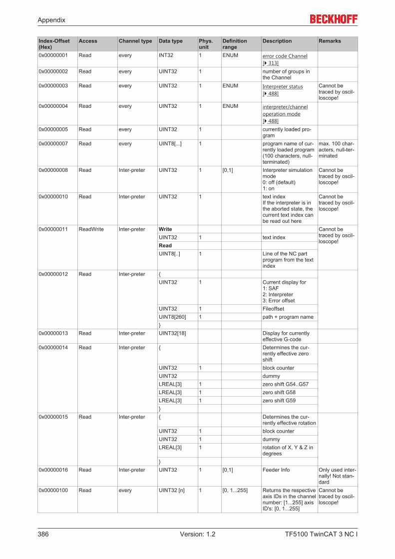
Appendix
TF5100 TwinCAT 3 NC I386 Version: 1.2
Index-Offset(Hex)
Access Channel type Data type Phys.unit
Definitionrange
Description Remarks
0x00000001 Read every INT32 1 ENUM error code Channel[} 313]
0x00000002 Read every UINT32 1 number of groups inthe Channel
0x00000003 Read every UINT32 1 ENUM Interpreter status[} 488]
Cannot betraced by oscil-loscope!
0x00000004 Read every UINT32 1 ENUM interpreter/channeloperation mode[} 488]
0x00000005 Read every UINT32 1 currently loaded pro-gram
0x00000007 Read every UINT8[...] 1 program name of cur-rently loaded program(100 characters, null-terminated)
max. 100 char-acters, null-ter-minated
0x00000008 Read Inter-preter UINT32 1 [0,1] Interpreter simulationmode0: off (default)1: on
Cannot betraced by oscil-loscope!
0x00000010 Read Inter-preter UINT32 1 text indexIf the interpreter is inthe aborted state, thecurrent text index canbe read out here
Cannot betraced by oscil-loscope!
0x00000011 ReadWrite Inter-preter Write Cannot betraced by oscil-loscope!
UINT32 1 text indexReadUINT8[..] 1 Line of the NC part
program from the textindex
0x00000012 Read Inter-preter {UINT32 1 Current display for
1: SAF2: Interpreter3: Error offset
UINT32 1 FileoffsetUINT8[260] 1 path + program name}
0x00000013 Read Inter-preter UINT32[18] Display for currentlyeffective G-code
0x00000014 Read Inter-preter { Determines the cur-rently effective zeroshift
UINT32 1 block counterUINT32 dummyLREAL[3] 1 zero shift G54..G57LREAL[3] 1 zero shift G58LREAL[3] 1 zero shift G59}
0x00000015 Read Inter-preter { Determines the cur-rently effective rotation
UINT32 1 block counterUINT32 1 dummyLREAL[3] 1 rotation of X, Y & Z in
degrees}
0x00000016 Read Inter-preter UINT32 1 [0,1] Feeder Info Only used inter-nally! Not stan-dard
0x00000100 Read every UINT32 [n] 1 [0, 1...255] Returns the respectiveaxis IDs in the channelnumber: [1...255] axisID's: [0, 1...255]
Cannot betraced by oscil-loscope!
Appendix
TF5100 TwinCAT 3 NC I 387Version: 1.2
7.8.2.3 "Index offset" specification for Channel functions (Index group 0x2200 +ID)
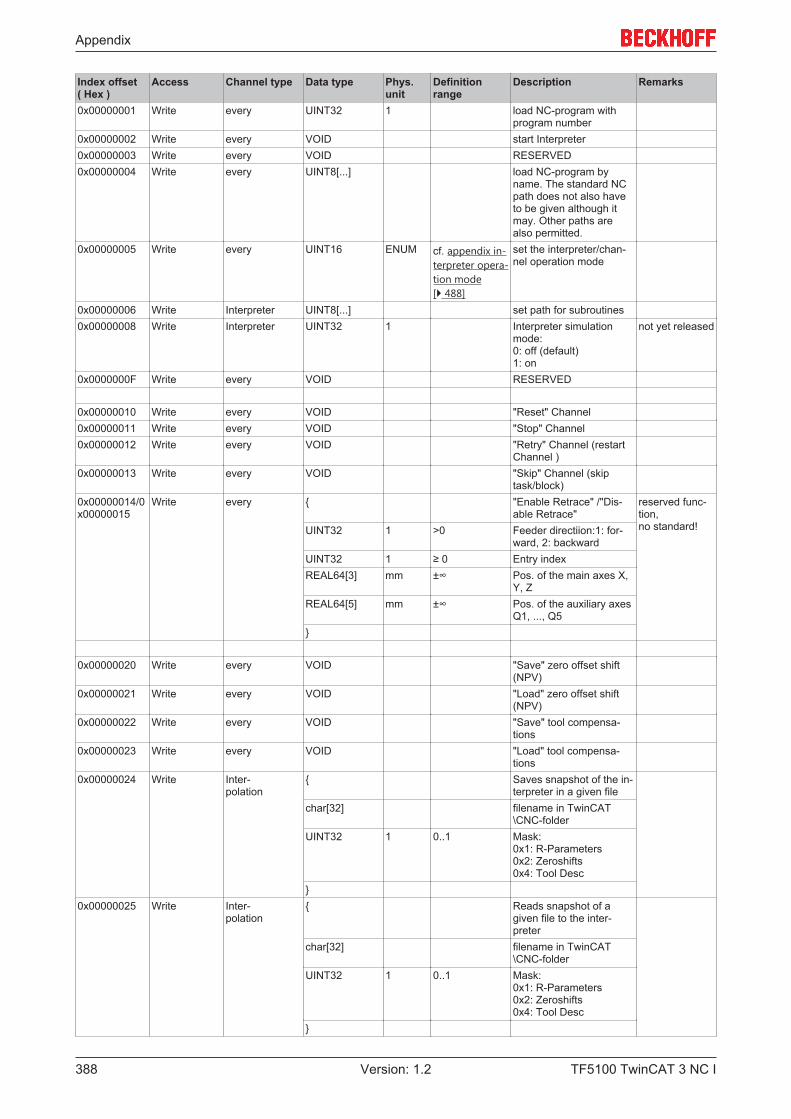
Appendix
TF5100 TwinCAT 3 NC I388 Version: 1.2
Index offset( Hex )
Access Channel type Data type Phys.unit
Definitionrange
Description Remarks
0x00000001 Write every UINT32 1 load NC-program withprogram number
0x00000002 Write every VOID start Interpreter0x00000003 Write every VOID RESERVED0x00000004 Write every UINT8[...] load NC-program by
name. The standard NCpath does not also haveto be given although itmay. Other paths arealso permitted.
0x00000005 Write every UINT16 ENUM cf. appendix in-terpreter opera-tion mode[} 488]
set the interpreter/chan-nel operation mode
0x00000006 Write Interpreter UINT8[...] set path for subroutines0x00000008 Write Interpreter UINT32 1 Interpreter simulation
mode: 0: off (default) 1: on
not yet released
0x0000000F Write every VOID RESERVED
0x00000010 Write every VOID "Reset" Channel0x00000011 Write every VOID "Stop" Channel0x00000012 Write every VOID "Retry" Channel (restart
Channel )0x00000013 Write every VOID "Skip" Channel (skip
task/block)0x00000014/0x00000015
Write every { "Enable Retrace" /"Dis-able Retrace"
reserved func-tion, no standard!UINT32 1 >0 Feeder directiion:1: for-
ward, 2: backwardUINT32 1 ≥ 0 Entry indexREAL64[3] mm ±∞ Pos. of the main axes X,
Y, ZREAL64[5] mm ±∞ Pos. of the auxiliary axes
Q1, ..., Q5}
0x00000020 Write every VOID "Save" zero offset shift(NPV)
0x00000021 Write every VOID "Load" zero offset shift(NPV)
0x00000022 Write every VOID "Save" tool compensa-tions
0x00000023 Write every VOID "Load" tool compensa-tions
0x00000024 Write Inter- polation
{ Saves snapshot of the in-terpreter in a given file
char[32] filename in TwinCAT\CNC-folder
UINT32 1 0..1 Mask: 0x1: R-Parameters 0x2: Zeroshifts 0x4: Tool Desc
}0x00000025 Write Inter-
polation{ Reads snapshot of a
given file to the inter-preter
char[32] filename in TwinCAT\CNC-folder
UINT32 1 0..1 Mask: 0x1: R-Parameters 0x2: Zeroshifts 0x4: Tool Desc
}

Appendix
TF5100 TwinCAT 3 NC I 389Version: 1.2
Index offset( Hex )
Access Channel type Data type Phys.unit
Definitionrange
Description Remarks
0x00000026 Write Inter- polation
VOID set all tool parameters(incl. type & number) tonull
0x00000027 Write Inter- polation
VOID set all zero offset shifts tonull
0x00000030 Write every VOID restart (Go Ahead) of theInterpreter after pro-grammed Interpreter stop
0x00000040 Write every VOID Triggerevent for deletionof any remaining travel inthe NCI
0x00000041 Write every RESERVED for fairevents
0x00000050 Write Inter- polation
VOID 1 set ExecIdleInfoin the in-terpreter
reserved func-tion, no standard!
0x00000051 Write Inter- polation
UINT32 1 set block skip mask in theinterpreter parameter: SkippingMask
reserved func-tion, no standard!
0x00000052 Write Inter- polation
UINT32 1 set ItpOperationModeinthe interpreter parameter: OperationMode mask
reserved func-tion, no standard!
0x00000053 Write Inter- polation
VOID set ScanningFlagin theNC device
reserved func-tion, no standard!
0x00000054 Write Inter- polation
scan position reserved func-tion, no standard!
double[8] position0x00000055 Write Inter-
polationreserved
0x00000056 Write Inter- polation
VOID set Interpreter in theAbortedstate
reserved func-tion, no standard!
0x00000060 Write Interp- polation
UINT16 1 0..159 manual reset of a fast MFunction
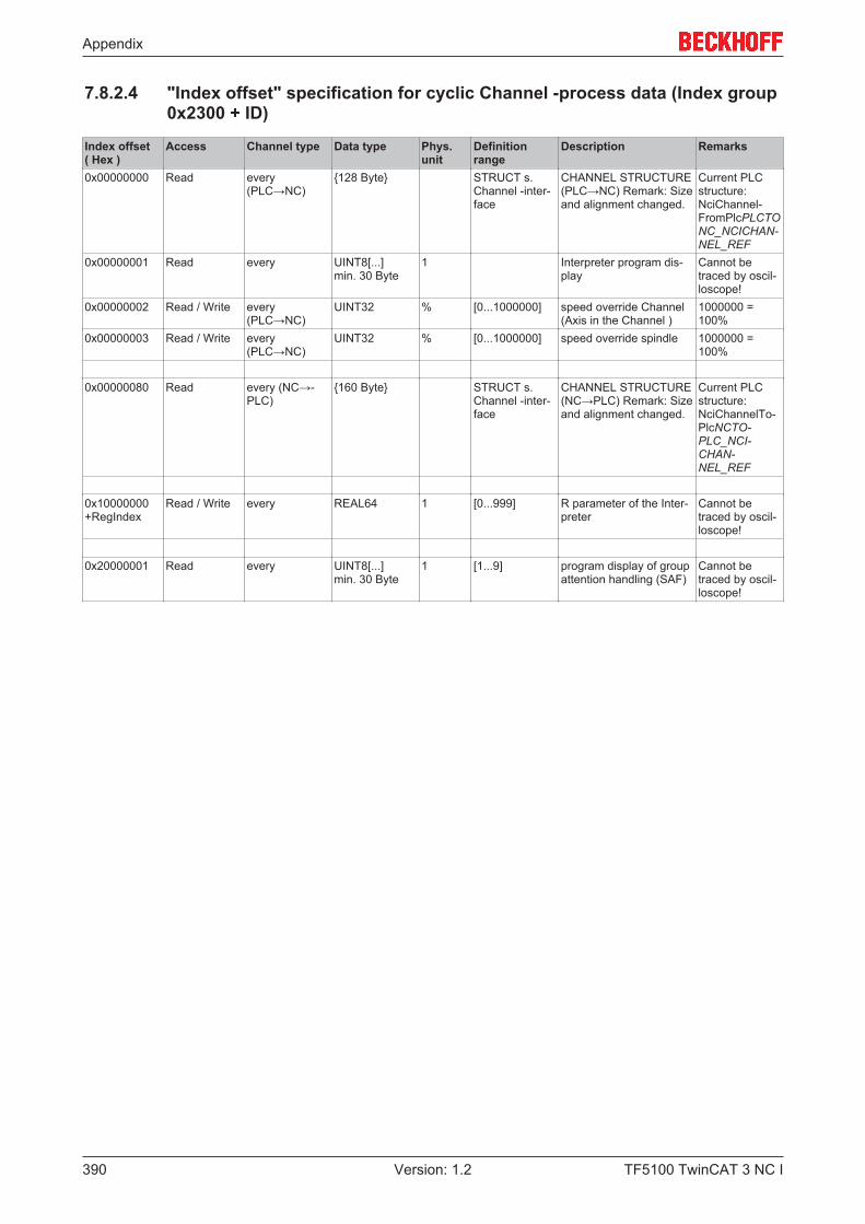
Appendix
TF5100 TwinCAT 3 NC I390 Version: 1.2
7.8.2.4 "Index offset" specification for cyclic Channel -process data (Index group0x2300 + ID)
Index offset( Hex )
Access Channel type Data type Phys.unit
Definitionrange
Description Remarks
0x00000000 Read every(PLC→NC)
{128 Byte} STRUCT s.Channel -inter-face
CHANNEL STRUCTURE(PLC→NC) Remark: Sizeand alignment changed.
Current PLCstructure:NciChannel-FromPlcPLCTONC_NCICHAN-NEL_REF
0x00000001 Read every UINT8[...]min. 30 Byte
1 Interpreter program dis-play
Cannot betraced by oscil-loscope!
0x00000002 Read / Write every(PLC→NC)
UINT32 % [0...1000000] speed override Channel(Axis in the Channel )
1000000 =100%
0x00000003 Read / Write every(PLC→NC)
UINT32 % [0...1000000] speed override spindle 1000000 =100%
0x00000080 Read every (NC→-PLC)
{160 Byte} STRUCT s.Channel -inter-face
CHANNEL STRUCTURE(NC→PLC) Remark: Sizeand alignment changed.
Current PLCstructure:NciChannelTo-PlcNCTO-PLC_NCI-CHAN-NEL_REF
0x10000000+RegIndex
Read / Write every REAL64 1 [0...999] R parameter of the Inter-preter
Cannot betraced by oscil-loscope!
0x20000001 Read every UINT8[...]min. 30 Byte
1 [1...9] program display of groupattention handling (SAF)
Cannot betraced by oscil-loscope!
Appendix
TF5100 TwinCAT 3 NC I 391Version: 1.2
7.8.3 Specification Groups
7.8.3.1 "Index offset" specification for group parameter (Index group 0x3000 +ID)
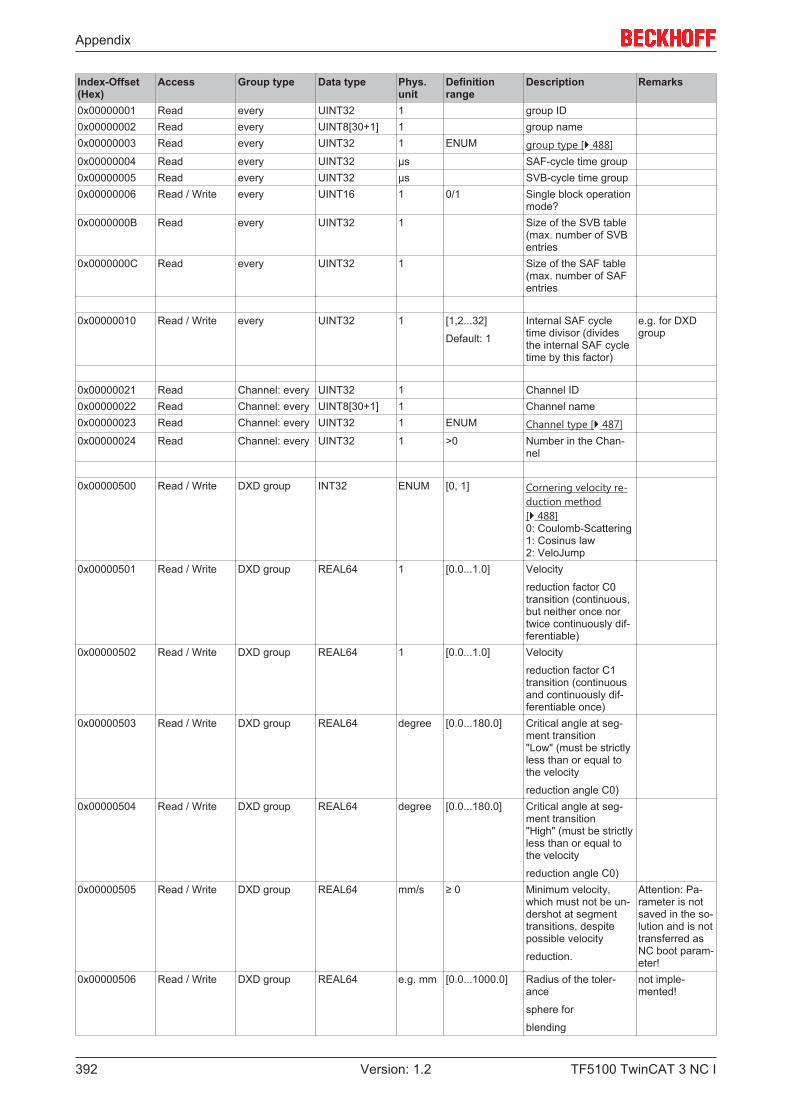
Appendix
TF5100 TwinCAT 3 NC I392 Version: 1.2
Index-Offset(Hex)
Access Group type Data type Phys.unit
Definitionrange
Description Remarks
0x00000001 Read every UINT32 1 group ID0x00000002 Read every UINT8[30+1] 1 group name0x00000003 Read every UINT32 1 ENUM group type [} 488]0x00000004 Read every UINT32 µs SAF-cycle time group0x00000005 Read every UINT32 µs SVB-cycle time group0x00000006 Read / Write every UINT16 1 0/1 Single block operation
mode?0x0000000B Read every UINT32 1 Size of the SVB table
(max. number of SVBentries
0x0000000C Read every UINT32 1 Size of the SAF table(max. number of SAFentries
0x00000010 Read / Write every UINT32 1 [1,2...32]
Default: 1
Internal SAF cycletime divisor (dividesthe internal SAF cycletime by this factor)
e.g. for DXDgroup
0x00000021 Read Channel: every UINT32 1 Channel ID0x00000022 Read Channel: every UINT8[30+1] 1 Channel name0x00000023 Read Channel: every UINT32 1 ENUM Channel type [} 487]0x00000024 Read Channel: every UINT32 1 >0 Number in the Chan-
nel
0x00000500 Read / Write DXD group INT32 ENUM [0, 1] Cornering velocity re-duction method[} 488] 0: Coulomb-Scattering1: Cosinus law2: VeloJump
0x00000501 Read / Write DXD group REAL64 1 [0.0...1.0] Velocity
reduction factor C0transition (continuous,but neither once nortwice continuously dif-ferentiable)
0x00000502 Read / Write DXD group REAL64 1 [0.0...1.0] Velocity
reduction factor C1transition (continuousand continuously dif-ferentiable once)
0x00000503 Read / Write DXD group REAL64 degree [0.0...180.0] Critical angle at seg-ment transition"Low" (must be strictlyless than or equal tothe velocity
reduction angle C0)0x00000504 Read / Write DXD group REAL64 degree [0.0...180.0] Critical angle at seg-
ment transition"High" (must be strictlyless than or equal tothe velocity
reduction angle C0)0x00000505 Read / Write DXD group REAL64 mm/s ≥ 0 Minimum velocity,
which must not be un-dershot at segmenttransitions, despitepossible velocity
reduction.
Attention: Pa-rameter is notsaved in the so-lution and is nottransferred asNC boot param-eter!
0x00000506 Read / Write DXD group REAL64 e.g. mm [0.0...1000.0] Radius of the toler-ance
sphere for
blending
not imple-mented!
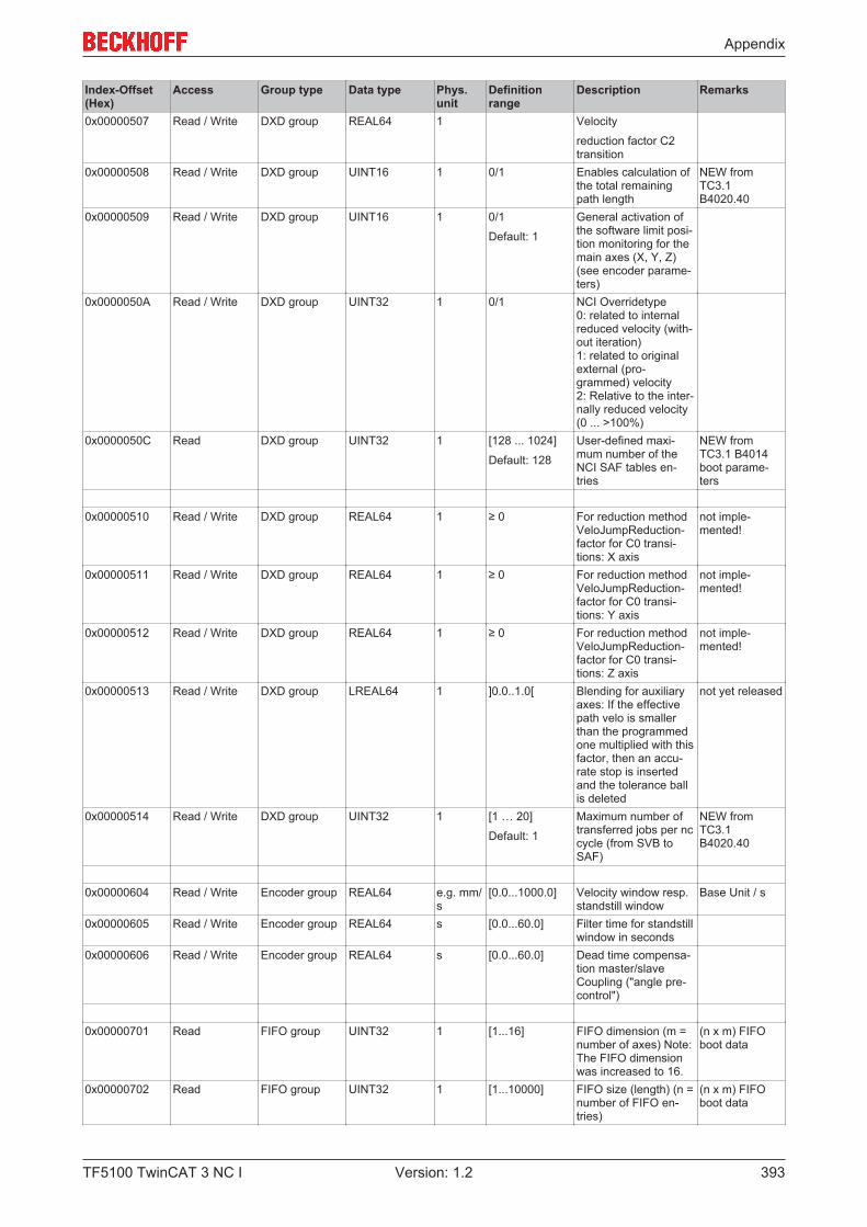
Appendix
TF5100 TwinCAT 3 NC I 393Version: 1.2
Index-Offset(Hex)
Access Group type Data type Phys.unit
Definitionrange
Description Remarks
0x00000507 Read / Write DXD group REAL64 1 Velocity
reduction factor C2transition
0x00000508 Read / Write DXD group UINT16 1 0/1 Enables calculation ofthe total remainingpath length
NEW fromTC3.1B4020.40
0x00000509 Read / Write DXD group UINT16 1 0/1
Default: 1
General activation ofthe software limit posi-tion monitoring for themain axes (X, Y, Z)(see encoder parame-ters)
0x0000050A Read / Write DXD group UINT32 1 0/1 NCI Overridetype0: related to internalreduced velocity (with-out iteration)1: related to originalexternal (pro-grammed) velocity2: Relative to the inter-nally reduced velocity(0 ... >100%)
0x0000050C Read DXD group UINT32 1 [128 ... 1024]
Default: 128
User-defined maxi-mum number of theNCI SAF tables en-tries
NEW fromTC3.1 B4014boot parame-ters
0x00000510 Read / Write DXD group REAL64 1 ≥ 0 For reduction methodVeloJumpReduction-factor for C0 transi-tions: X axis
not imple-mented!
0x00000511 Read / Write DXD group REAL64 1 ≥ 0 For reduction methodVeloJumpReduction-factor for C0 transi-tions: Y axis
not imple-mented!
0x00000512 Read / Write DXD group REAL64 1 ≥ 0 For reduction methodVeloJumpReduction-factor for C0 transi-tions: Z axis
not imple-mented!
0x00000513 Read / Write DXD group LREAL64 1 ]0.0..1.0[ Blending for auxiliaryaxes: If the effectivepath velo is smallerthan the programmedone multiplied with thisfactor, then an accu-rate stop is insertedand the tolerance ballis deleted
not yet released
0x00000514 Read / Write DXD group UINT32 1 [1 … 20]
Default: 1
Maximum number oftransferred jobs per nccycle (from SVB toSAF)
NEW fromTC3.1B4020.40
0x00000604 Read / Write Encoder group REAL64 e.g. mm/s
[0.0...1000.0] Velocity window resp.standstill window
Base Unit / s
0x00000605 Read / Write Encoder group REAL64 s [0.0...60.0] Filter time for standstillwindow in seconds
0x00000606 Read / Write Encoder group REAL64 s [0.0...60.0] Dead time compensa-tion master/slave Coupling ("angle pre-control")
0x00000701 Read FIFO group UINT32 1 [1...16] FIFO dimension (m =number of axes) Note:The FIFO dimensionwas increased to 16.
(n x m) FIFOboot data
0x00000702 Read FIFO group UINT32 1 [1...10000] FIFO size (length) (n =number of FIFO en-tries)
(n x m) FIFOboot data
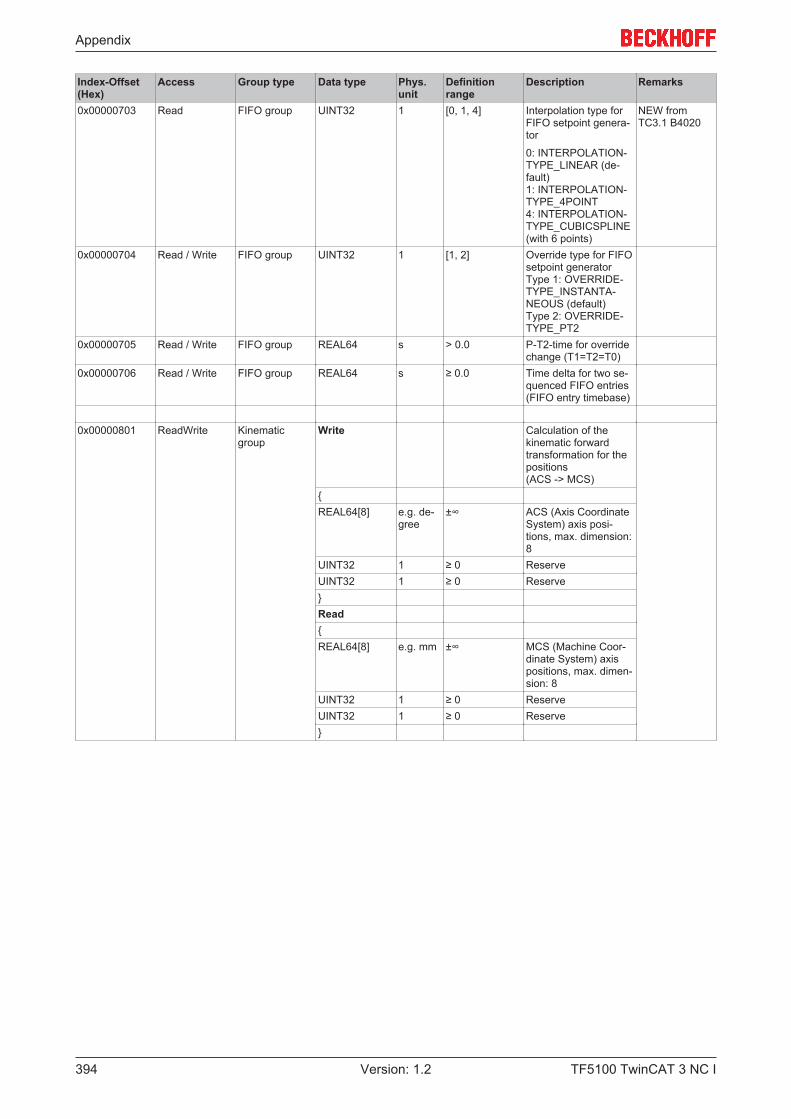
Appendix
TF5100 TwinCAT 3 NC I394 Version: 1.2
Index-Offset(Hex)
Access Group type Data type Phys.unit
Definitionrange
Description Remarks
0x00000703 Read FIFO group UINT32 1 [0, 1, 4] Interpolation type forFIFO setpoint genera-tor
0: INTERPOLATION-TYPE_LINEAR (de-fault)1: INTERPOLATION-TYPE_4POINT4: INTERPOLATION-TYPE_CUBICSPLINE(with 6 points)
NEW fromTC3.1 B4020
0x00000704 Read / Write FIFO group UINT32 1 [1, 2] Override type for FIFOsetpoint generatorType 1: OVERRIDE-TYPE_INSTANTA-NEOUS (default)Type 2: OVERRIDE-TYPE_PT2
0x00000705 Read / Write FIFO group REAL64 s > 0.0 P-T2-time for overridechange (T1=T2=T0)
0x00000706 Read / Write FIFO group REAL64 s ≥ 0.0 Time delta for two se-quenced FIFO entries(FIFO entry timebase)
0x00000801 ReadWrite Kinematicgroup
Write Calculation of thekinematic forwardtransformation for thepositions(ACS -> MCS)
{REAL64[8] e.g. de-
gree±∞ ACS (Axis Coordinate
System) axis posi-tions, max. dimension:8
UINT32 1 ≥ 0 ReserveUINT32 1 ≥ 0 Reserve}Read{REAL64[8] e.g. mm ±∞ MCS (Machine Coor-
dinate System) axispositions, max. dimen-sion: 8
UINT32 1 ≥ 0 ReserveUINT32 1 ≥ 0 Reserve}
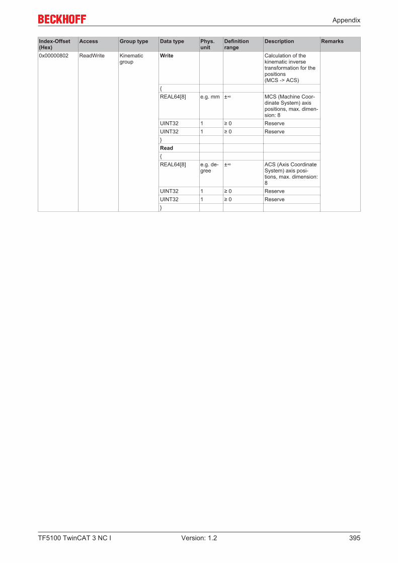
Appendix
TF5100 TwinCAT 3 NC I 395Version: 1.2
Index-Offset(Hex)
Access Group type Data type Phys.unit
Definitionrange
Description Remarks
0x00000802 ReadWrite Kinematicgroup
Write Calculation of thekinematic inversetransformation for thepositions(MCS -> ACS)
{REAL64[8] e.g. mm ±∞ MCS (Machine Coor-
dinate System) axispositions, max. dimen-sion: 8
UINT32 1 ≥ 0 ReserveUINT32 1 ≥ 0 Reserve}Read{REAL64[8] e.g. de-
gree±∞ ACS (Axis Coordinate
System) axis posi-tions, max. dimension:8
UINT32 1 ≥ 0 ReserveUINT32 1 ≥ 0 Reserve}

Appendix
TF5100 TwinCAT 3 NC I396 Version: 1.2
7.8.3.2 "Index offset" specification for Group state (Index group 0x3100 + ID)
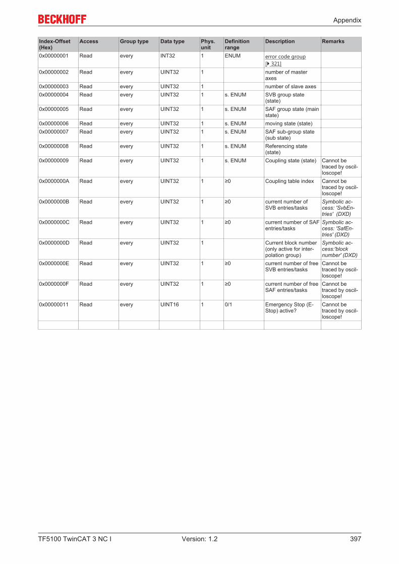
Appendix
TF5100 TwinCAT 3 NC I 397Version: 1.2
Index-Offset(Hex)
Access Group type Data type Phys.unit
Definitionrange
Description Remarks
0x00000001 Read every INT32 1 ENUM error code group[} 321]
0x00000002 Read every UINT32 1 number of masteraxes
0x00000003 Read every UINT32 1 number of slave axes0x00000004 Read every UINT32 1 s. ENUM SVB group state
(state)0x00000005 Read every UINT32 1 s. ENUM SAF group state (main
state)0x00000006 Read every UINT32 1 s. ENUM moving state (state)0x00000007 Read every UINT32 1 s. ENUM SAF sub-group state
(sub state)0x00000008 Read every UINT32 1 s. ENUM Referencing state
(state)0x00000009 Read every UINT32 1 s. ENUM Coupling state (state) Cannot be
traced by oscil-loscope!
0x0000000A Read every UINT32 1 ≥0 Coupling table index Cannot betraced by oscil-loscope!
0x0000000B Read every UINT32 1 ≥0 current number ofSVB entries/tasks
Symbolic ac-cess: 'SvbEn-tries' (DXD)
0x0000000C Read every UINT32 1 ≥0 current number of SAFentries/tasks
Symbolic ac-cess: 'SafEn-tries' (DXD)
0x0000000D Read every UINT32 1 Current block number(only active for inter-polation group)
Symbolic ac-cess:'blocknumber' (DXD)
0x0000000E Read every UINT32 1 ≥0 current number of freeSVB entries/tasks
Cannot betraced by oscil-loscope!
0x0000000F Read every UINT32 1 ≥0 current number of freeSAF entries/tasks
Cannot betraced by oscil-loscope!
0x00000011 Read every UINT16 1 0/1 Emergency Stop (E-Stop) active?
Cannot betraced by oscil-loscope!
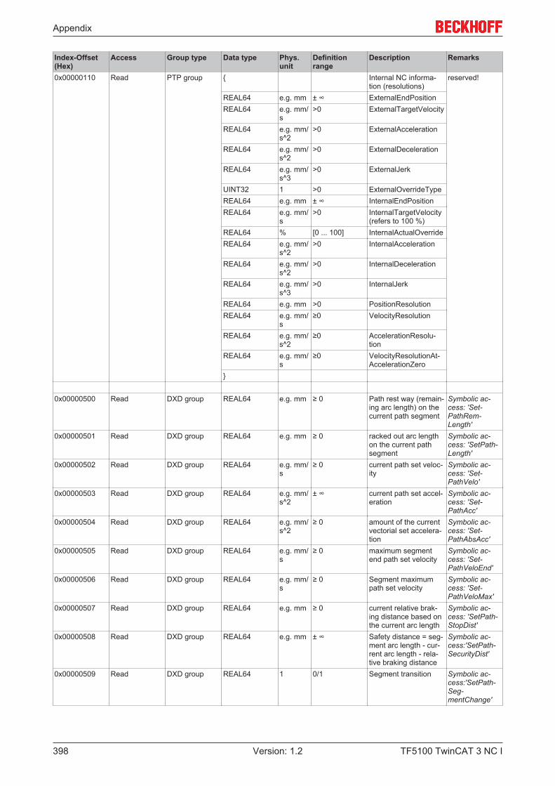
Appendix
TF5100 TwinCAT 3 NC I398 Version: 1.2
Index-Offset(Hex)
Access Group type Data type Phys.unit
Definitionrange
Description Remarks
0x00000110 Read PTP group { Internal NC informa-tion (resolutions)
reserved!
REAL64 e.g. mm ± ∞ ExternalEndPositionREAL64 e.g. mm/
s>0 ExternalTargetVelocity
REAL64 e.g. mm/s^2
>0 ExternalAcceleration
REAL64 e.g. mm/s^2
>0 ExternalDeceleration
REAL64 e.g. mm/s^3
>0 ExternalJerk
UINT32 1 >0 ExternalOverrideTypeREAL64 e.g. mm ± ∞ InternalEndPositionREAL64 e.g. mm/
s>0 InternalTargetVelocity
(refers to 100 %)REAL64 % [0 ... 100] InternalActualOverrideREAL64 e.g. mm/
s^2>0 InternalAcceleration
REAL64 e.g. mm/s^2
>0 InternalDeceleration
REAL64 e.g. mm/s^3
>0 InternalJerk
REAL64 e.g. mm >0 PositionResolutionREAL64 e.g. mm/
s≥0 VelocityResolution
REAL64 e.g. mm/s^2
≥0 AccelerationResolu-tion
REAL64 e.g. mm/s
≥0 VelocityResolutionAt-AccelerationZero
}
0x00000500 Read DXD group REAL64 e.g. mm ≥ 0 Path rest way (remain-ing arc length) on thecurrent path segment
Symbolic ac-cess: 'Set-PathRem-Length'
0x00000501 Read DXD group REAL64 e.g. mm ≥ 0 racked out arc lengthon the current pathsegment
Symbolic ac-cess: 'SetPath-Length'
0x00000502 Read DXD group REAL64 e.g. mm/s
≥ 0 current path set veloc-ity
Symbolic ac-cess: 'Set-PathVelo'
0x00000503 Read DXD group REAL64 e.g. mm/s^2
± ∞ current path set accel-eration
Symbolic ac-cess: 'Set-PathAcc'
0x00000504 Read DXD group REAL64 e.g. mm/s^2
≥ 0 amount of the currentvectorial set accelera-tion
Symbolic ac-cess: 'Set-PathAbsAcc'
0x00000505 Read DXD group REAL64 e.g. mm/s
≥ 0 maximum segmentend path set velocity
Symbolic ac-cess: 'Set-PathVeloEnd'
0x00000506 Read DXD group REAL64 e.g. mm/s
≥ 0 Segment maximumpath set velocity
Symbolic ac-cess: 'Set-PathVeloMax'
0x00000507 Read DXD group REAL64 e.g. mm ≥ 0 current relative brak-ing distance based onthe current arc length
Symbolic ac-cess: 'SetPath-StopDist'
0x00000508 Read DXD group REAL64 e.g. mm ± ∞ Safety distance = seg-ment arc length - cur-rent arc length - rela-tive braking distance
Symbolic ac-cess:'SetPath-SecurityDist'
0x00000509 Read DXD group REAL64 1 0/1 Segment transition Symbolic ac-cess:'SetPath-Seg-mentChange'
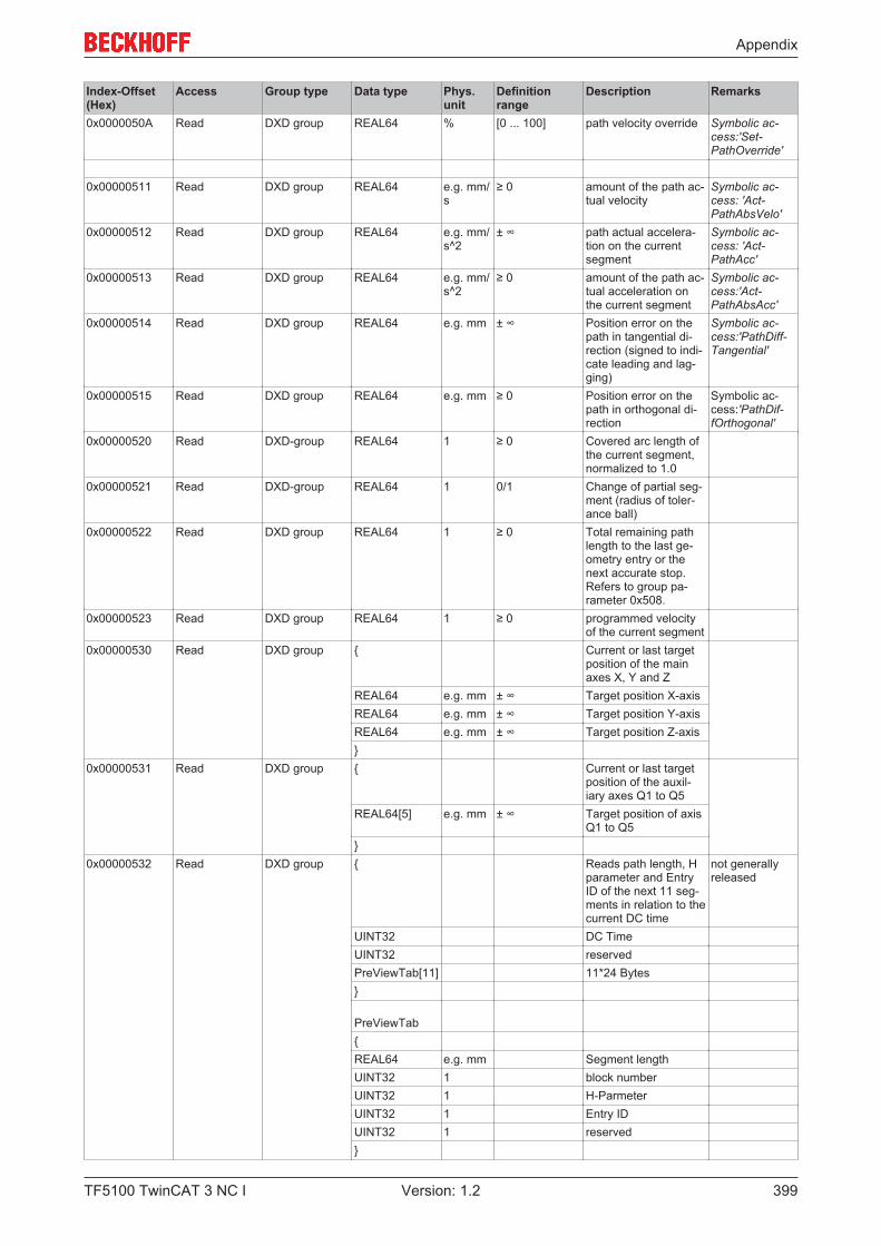
Appendix
TF5100 TwinCAT 3 NC I 399Version: 1.2
Index-Offset(Hex)
Access Group type Data type Phys.unit
Definitionrange
Description Remarks
0x0000050A Read DXD group REAL64 % [0 ... 100] path velocity override Symbolic ac-cess:'Set-PathOverride'
0x00000511 Read DXD group REAL64 e.g. mm/s
≥ 0 amount of the path ac-tual velocity
Symbolic ac-cess: 'Act-PathAbsVelo'
0x00000512 Read DXD group REAL64 e.g. mm/s^2
± ∞ path actual accelera-tion on the currentsegment
Symbolic ac-cess: 'Act-PathAcc'
0x00000513 Read DXD group REAL64 e.g. mm/s^2
≥ 0 amount of the path ac-tual acceleration onthe current segment
Symbolic ac-cess:'Act-PathAbsAcc'
0x00000514 Read DXD group REAL64 e.g. mm ± ∞ Position error on thepath in tangential di-rection (signed to indi-cate leading and lag-ging)
Symbolic ac-cess:'PathDiff-Tangential'
0x00000515 Read DXD group REAL64 e.g. mm ≥ 0 Position error on thepath in orthogonal di-rection
Symbolic ac-cess:'PathDif-fOrthogonal'
0x00000520 Read DXD-group REAL64 1 ≥ 0 Covered arc length ofthe current segment,normalized to 1.0
0x00000521 Read DXD-group REAL64 1 0/1 Change of partial seg-ment (radius of toler-ance ball)
0x00000522 Read DXD group REAL64 1 ≥ 0 Total remaining pathlength to the last ge-ometry entry or thenext accurate stop.Refers to group pa-rameter 0x508.
0x00000523 Read DXD group REAL64 1 ≥ 0 programmed velocityof the current segment
0x00000530 Read DXD group { Current or last targetposition of the mainaxes X, Y and Z
REAL64 e.g. mm ± ∞ Target position X-axisREAL64 e.g. mm ± ∞ Target position Y-axisREAL64 e.g. mm ± ∞ Target position Z-axis}
0x00000531 Read DXD group { Current or last targetposition of the auxil-iary axes Q1 to Q5
REAL64[5] e.g. mm ± ∞ Target position of axisQ1 to Q5
}0x00000532 Read DXD group { Reads path length, H
parameter and EntryID of the next 11 seg-ments in relation to thecurrent DC time
not generallyreleased
UINT32 DC TimeUINT32 reservedPreViewTab[11] 11*24 Bytes}
PreViewTab{REAL64 e.g. mm Segment lengthUINT32 1 block numberUINT32 1 H-ParmeterUINT32 1 Entry IDUINT32 1 reserved}
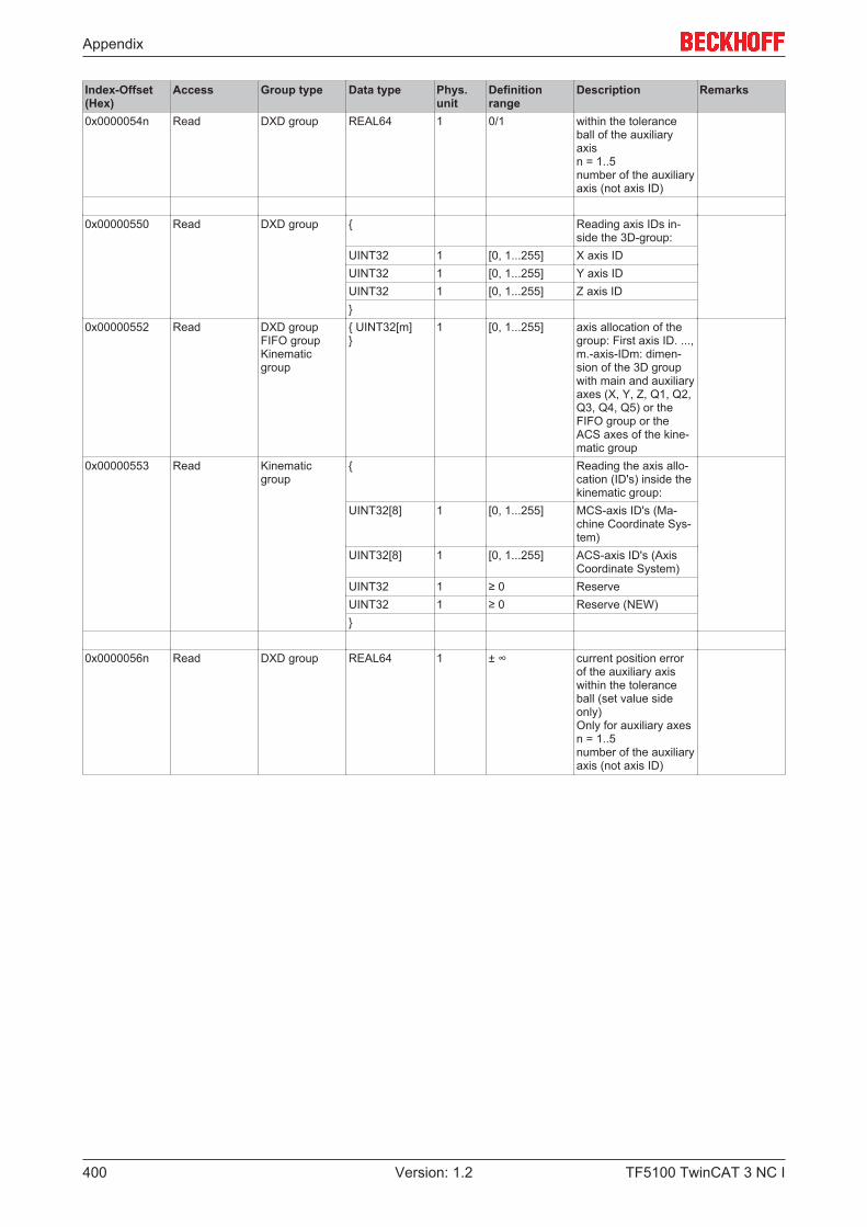
Appendix
TF5100 TwinCAT 3 NC I400 Version: 1.2
Index-Offset(Hex)
Access Group type Data type Phys.unit
Definitionrange
Description Remarks
0x0000054n Read DXD group REAL64 1 0/1 within the toleranceball of the auxiliaryaxisn = 1..5number of the auxiliaryaxis (not axis ID)
0x00000550 Read DXD group { Reading axis IDs in-side the 3D-group:
UINT32 1 [0, 1...255] X axis IDUINT32 1 [0, 1...255] Y axis IDUINT32 1 [0, 1...255] Z axis ID}
0x00000552 Read DXD groupFIFO groupKinematicgroup
{ UINT32[m]}
1 [0, 1...255] axis allocation of thegroup: First axis ID. ...,m.-axis-IDm: dimen-sion of the 3D groupwith main and auxiliaryaxes (X, Y, Z, Q1, Q2,Q3, Q4, Q5) or theFIFO group or theACS axes of the kine-matic group
0x00000553 Read Kinematicgroup
{ Reading the axis allo-cation (ID's) inside thekinematic group:
UINT32[8] 1 [0, 1...255] MCS-axis ID's (Ma-chine Coordinate Sys-tem)
UINT32[8] 1 [0, 1...255] ACS-axis ID's (AxisCoordinate System)
UINT32 1 ≥ 0 ReserveUINT32 1 ≥ 0 Reserve (NEW)}
0x0000056n Read DXD group REAL64 1 ± ∞ current position errorof the auxiliary axiswithin the toleranceball (set value sideonly)Only for auxiliary axesn = 1..5number of the auxiliaryaxis (not axis ID)
Appendix
TF5100 TwinCAT 3 NC I 401Version: 1.2
7.8.3.3 "Index offset" specification for Group functions (Index group 0x3200 + ID)
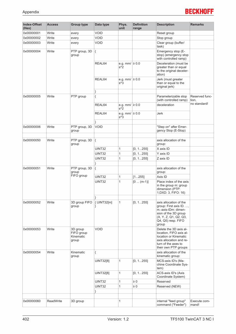
Appendix
TF5100 TwinCAT 3 NC I402 Version: 1.2
Index-Offset(Hex)
Access Group type Data type Phys.unit
Definitionrange
Description Remarks
0x00000001 Write every VOID Reset group0x00000002 Write every VOID Stop group0x00000003 Write every VOID Clear group (buffer/
task)0x00000004 Write PTP group, 3D
group{ Emergency stop (E-
stop) (emergency stopwith controlled ramp)
REAL64 e.g. mm/s^2
≥ 0.0 Deceleration (must begreater than or equalto the original deceler-ation)
REAL64 e.g. mm/s^3
≥ 0.0 Jerk (must greaterthan or equal to theoriginal jerk)
}0x00000005 Write PTP group { Parameterizable stop
(with controlled ramp)Reserved func-tion,no standard!REAL64 e.g. mm/
s^2≥ 0.0 deceleration
REAL64 e.g. mm/s^3
≥ 0.0 Jerk
}0x00000006 Write PTP group, 3D
groupVOID "Step on" after Emer-
gency Stop (E-Stop)
0x00000050 Write PTP group, 3Dgroup
{ axis allocation of thegroup:
UINT32 1 [0, 1...255] X axis IDUINT32 1 [0, 1...255] Y axis IDUINT32 1 [0, 1...255] Z axis ID}
0x00000051 Write PTP group, 3DgroupFIFO group
{ axis allocation of thegroup:
UINT32 1 [1...255] Axis IDUINT32 1 [0 ... (m-1)] Place index of the axis
in the group m: groupdimension (PTP:1;DXD: 3, FIFO: 16)
}0x00000052 Write 3D group FIFO
group{ UINT32[m] }
1 [0, 1...255] axis allocation of thegroup: First axis ID. ...,m.-axis-IDm: dimen-sion of the 3D group(X, Y, Z, Q1, Q2, Q3,Q4, Q5) resp. FIFOgroup
0x00000053 Write 3D groupFIFO groupKinematicgroup
VOID Delete the 3D axis al-location, FIFO axis al-location or Kinematicaxis allocation and re-turn of the axes totheir own PTP groups
0x00000054 Write Kinematicgroup
{ axis allocation of thekinematic group:
UINT32[8] 1 [0, 1...255] MCS-axis ID's (Ma-chine Coordinate Sys-tem)
UINT32[8] 1 [0, 1...255] ACS-axis ID's (AxisCoordinate System)
UINT32 1 ≥ 0 ReservedUINT32 1 ≥ 0 Reserved (NEW)}
0x00000060 ReadWrite 3D group 1 internal "feed group"command ("Feeder")
Execute com-mand!
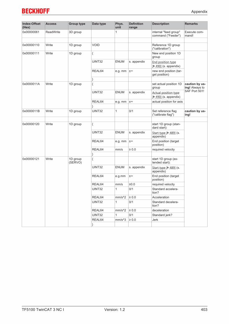
Appendix
TF5100 TwinCAT 3 NC I 403Version: 1.2
Index-Offset(Hex)
Access Group type Data type Phys.unit
Definitionrange
Description Remarks
0x00000061 ReadWrite 3D group 1 internal "feed group"command ("Feeder")
Execute com-mand!
0x00000110 Write 1D group VOID Reference 1D group("calibration")
0x00000111 Write 1D group { New end position 1Dgroup
UINT32 ENUM s. appendix End position type[} 490] (s. appendix)
REAL64 e.g. mm ±∞ new end position (tar-get position)
}0x0000011A Write 1D group { set actual position 1D
groupcaution by us-ing! Always toSAF Port 501!UINT32 ENUM s. appendix Actual position type
[} 490] (s. appendix)REAL64 e.g. mm ±∞ actual position for axis}
0x0000011B Write 1D group UINT32 1 0/1 Set reference flag("calibrate flag")
caution by us-ing!
0x00000120 Write 1D group { start 1D group (stan-dard start):
UINT32 ENUM s. appendix Start type [} 489] (s.appendix)
REAL64 e.g. mm ±∞ End position (targetposition)
REAL64 mm/s ≥ 0.0 required velocity}
0x00000121 Write 1D group(SERVO)
{ start 1D group (ex-tended start):
UINT32 ENUM s. appendix Start type [} 489] (s.appendix)
REAL64 e.g.mm ±∞ End position (targetposition)
REAL64 mm/s ≥0.0 required velocityUINT32 1 0/1 Standard accelera-
tion?REAL64 mm/s^2 ≥ 0.0 AccelerationUINT32 1 0/1 Standard decelera-
tion?REAL64 mm/s^2 ≥ 0.0 decelerationUINT32 1 0/1 Standard jerk?REAL64 mm/s^3 ≥ 0.0 Jerk}
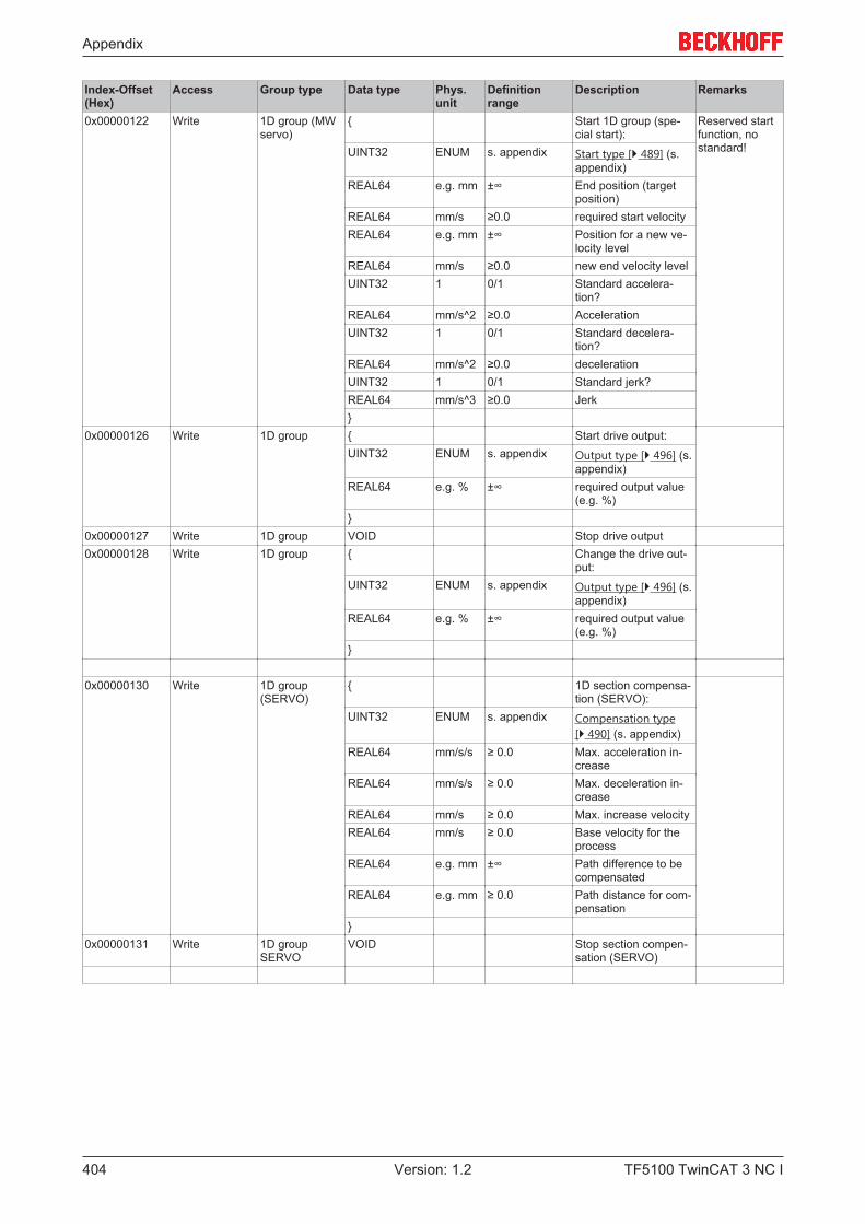
Appendix
TF5100 TwinCAT 3 NC I404 Version: 1.2
Index-Offset(Hex)
Access Group type Data type Phys.unit
Definitionrange
Description Remarks
0x00000122 Write 1D group (MWservo)
{ Start 1D group (spe-cial start):
Reserved startfunction, nostandard!UINT32 ENUM s. appendix Start type [} 489] (s.
appendix)REAL64 e.g. mm ±∞ End position (target
position)REAL64 mm/s ≥0.0 required start velocityREAL64 e.g. mm ±∞ Position for a new ve-
locity levelREAL64 mm/s ≥0.0 new end velocity levelUINT32 1 0/1 Standard accelera-
tion?REAL64 mm/s^2 ≥0.0 AccelerationUINT32 1 0/1 Standard decelera-
tion?REAL64 mm/s^2 ≥0.0 decelerationUINT32 1 0/1 Standard jerk?REAL64 mm/s^3 ≥0.0 Jerk}
0x00000126 Write 1D group { Start drive output:UINT32 ENUM s. appendix Output type [} 496] (s.
appendix)REAL64 e.g. % ±∞ required output value
(e.g. %)}
0x00000127 Write 1D group VOID Stop drive output0x00000128 Write 1D group { Change the drive out-
put:UINT32 ENUM s. appendix Output type [} 496] (s.
appendix)REAL64 e.g. % ±∞ required output value
(e.g. %)}
0x00000130 Write 1D group(SERVO)
{ 1D section compensa-tion (SERVO):
UINT32 ENUM s. appendix Compensation type[} 490] (s. appendix)
REAL64 mm/s/s ≥ 0.0 Max. acceleration in-crease
REAL64 mm/s/s ≥ 0.0 Max. deceleration in-crease
REAL64 mm/s ≥ 0.0 Max. increase velocityREAL64 mm/s ≥ 0.0 Base velocity for the
processREAL64 e.g. mm ±∞ Path difference to be
compensatedREAL64 e.g. mm ≥ 0.0 Path distance for com-
pensation}
0x00000131 Write 1D groupSERVO
VOID Stop section compen-sation (SERVO)
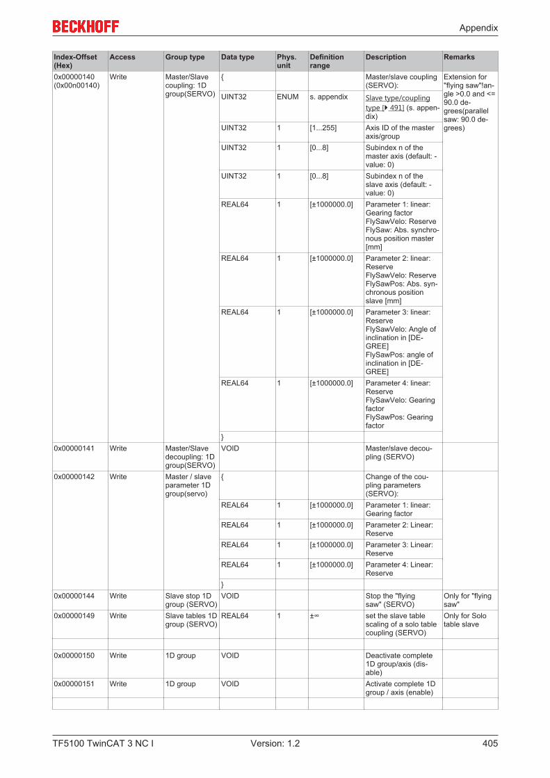
Appendix
TF5100 TwinCAT 3 NC I 405Version: 1.2
Index-Offset(Hex)
Access Group type Data type Phys.unit
Definitionrange
Description Remarks
0x00000140(0x00n00140)
Write Master/Slavecoupling: 1Dgroup(SERVO)
{ Master/slave coupling(SERVO):
Extension for"flying saw"!an-gle >0.0 and <=90.0 de-grees(parallelsaw: 90.0 de-grees)
UINT32 ENUM s. appendix Slave type/couplingtype [} 491] (s. appen-dix)
UINT32 1 [1...255] Axis ID of the masteraxis/group
UINT32 1 [0...8] Subindex n of themaster axis (default: -value: 0)
UINT32 1 [0...8] Subindex n of theslave axis (default: -value: 0)
REAL64 1 [±1000000.0] Parameter 1: linear:Gearing factorFlySawVelo: ReserveFlySaw: Abs. synchro-nous position master[mm]
REAL64 1 [±1000000.0] Parameter 2: linear:ReserveFlySawVelo: ReserveFlySawPos: Abs. syn-chronous positionslave [mm]
REAL64 1 [±1000000.0] Parameter 3: linear:ReserveFlySawVelo: Angle ofinclination in [DE-GREE]FlySawPos: angle ofinclination in [DE-GREE]
REAL64 1 [±1000000.0] Parameter 4: linear:ReserveFlySawVelo: GearingfactorFlySawPos: Gearingfactor
}0x00000141 Write Master/Slave
decoupling: 1Dgroup(SERVO)
VOID Master/slave decou-pling (SERVO)
0x00000142 Write Master / slaveparameter 1Dgroup(servo)
{ Change of the cou-pling parameters(SERVO):
REAL64 1 [±1000000.0] Parameter 1: linear:Gearing factor
REAL64 1 [±1000000.0] Parameter 2: Linear:Reserve
REAL64 1 [±1000000.0] Parameter 3: Linear:Reserve
REAL64 1 [±1000000.0] Parameter 4: Linear:Reserve
}0x00000144 Write Slave stop 1D
group (SERVO)VOID Stop the "flying
saw" (SERVO)Only for "flyingsaw"
0x00000149 Write Slave tables 1Dgroup (SERVO)
REAL64 1 ±∞ set the slave tablescaling of a solo tablecoupling (SERVO)
Only for Solotable slave
0x00000150 Write 1D group VOID Deactivate complete1D group/axis (dis-able)
0x00000151 Write 1D group VOID Activate complete 1Dgroup / axis (enable)
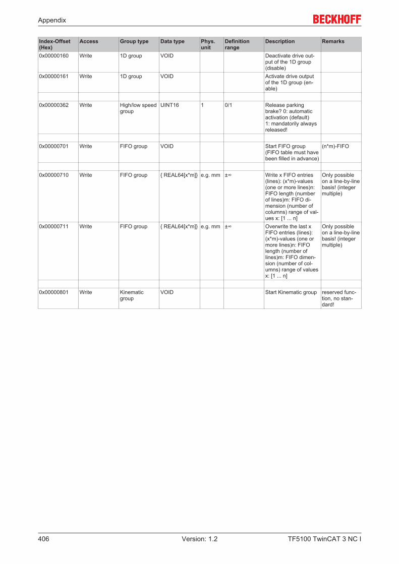
Appendix
TF5100 TwinCAT 3 NC I406 Version: 1.2
Index-Offset(Hex)
Access Group type Data type Phys.unit
Definitionrange
Description Remarks
0x00000160 Write 1D group VOID Deactivate drive out-put of the 1D group(disable)
0x00000161 Write 1D group VOID Activate drive outputof the 1D group (en-able)
0x00000362 Write High/low speedgroup
UINT16 1 0/1 Release parkingbrake? 0: automaticactivation (default)1: mandatorily alwaysreleased!
0x00000701 Write FIFO group VOID Start FIFO group(FIFO table must havebeen filled in advance)
(n*m)-FIFO
0x00000710 Write FIFO group { REAL64[x*m]} e.g. mm ±∞ Write x FIFO entries(lines): (x*m)-values(one or more lines)n:FIFO length (numberof lines)m: FIFO di-mension (number ofcolumns) range of val-ues x: [1 ... n]
Only possibleon a line-by-linebasis! (integermultiple)
0x00000711 Write FIFO group { REAL64[x*m]} e.g. mm ±∞ Overwrite the last xFIFO entries (lines):(x*m)-values (one ormore lines)n: FIFOlength (number oflines)m: FIFO dimen-sion (number of col-umns) range of valuesx: [1 ... n]
Only possibleon a line-by-linebasis! (integermultiple)
0x00000801 Write Kinematicgroup
VOID Start Kinematic group reserved func-tion, no stan-dard!

Appendix
TF5100 TwinCAT 3 NC I 407Version: 1.2
7.8.4 Specification Axes
7.8.4.1 "Index offset" specification for Axis parameter (Index group 0x4000 + ID)
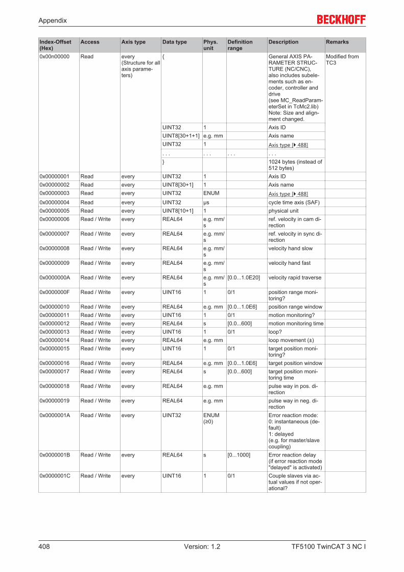
Appendix
TF5100 TwinCAT 3 NC I408 Version: 1.2
Index-Offset(Hex)
Access Axis type Data type Phys.unit
Definitionrange
Description Remarks
0x00n00000 Read every(Structure for allaxis parame-ters)
{ General AXIS PA-RAMETER STRUC-TURE (NC/CNC),also includes subele-ments such as en-coder, controller anddrive(see MC_ReadParam-eterSet in TcMc2.lib)Note: Size and align-ment changed.
Modified fromTC3
UINT32 1 Axis IDUINT8[30+1+1] e.g. mm Axis nameUINT32 1 Axis type [} 488]. . . . . . . . . . . .} 1024 bytes (instead of
512 bytes)0x00000001 Read every UINT32 1 Axis ID0x00000002 Read every UINT8[30+1] 1 Axis name0x00000003 Read every UINT32 ENUM Axis type [} 488]0x00000004 Read every UINT32 µs cycle time axis (SAF)0x00000005 Read every UINT8[10+1] 1 physical unit0x00000006 Read / Write every REAL64 e.g. mm/
sref. velocity in cam di-rection
0x00000007 Read / Write every REAL64 e.g. mm/s
ref. velocity in sync di-rection
0x00000008 Read / Write every REAL64 e.g. mm/s
velocity hand slow
0x00000009 Read / Write every REAL64 e.g. mm/s
velocity hand fast
0x0000000A Read / Write every REAL64 e.g. mm/s
[0.0...1.0E20] velocity rapid traverse
0x0000000F Read / Write every UINT16 1 0/1 position range moni-toring?
0x00000010 Read / Write every REAL64 e.g. mm [0.0...1.0E6] position range window0x00000011 Read / Write every UINT16 1 0/1 motion monitoring?0x00000012 Read / Write every REAL64 s [0.0...600] motion monitoring time0x00000013 Read / Write every UINT16 1 0/1 loop?0x00000014 Read / Write every REAL64 e.g. mm loop movement (±)0x00000015 Read / Write every UINT16 1 0/1 target position moni-
toring?0x00000016 Read / Write every REAL64 e.g. mm [0.0...1.0E6] target position window0x00000017 Read / Write every REAL64 s [0.0...600] target position moni-
toring time0x00000018 Read / Write every REAL64 e.g. mm pulse way in pos. di-
rection0x00000019 Read / Write every REAL64 e.g. mm pulse way in neg. di-
rection0x0000001A Read / Write every UINT32 ENUM
(≥0)Error reaction mode:0: instantaneous (de-fault)1: delayed(e.g. for master/slavecoupling)
0x0000001B Read / Write every REAL64 s [0...1000] Error reaction delay(if error reaction mode"delayed" is activated)
0x0000001C Read / Write every UINT16 1 0/1 Couple slaves via ac-tual values if not oper-ational?
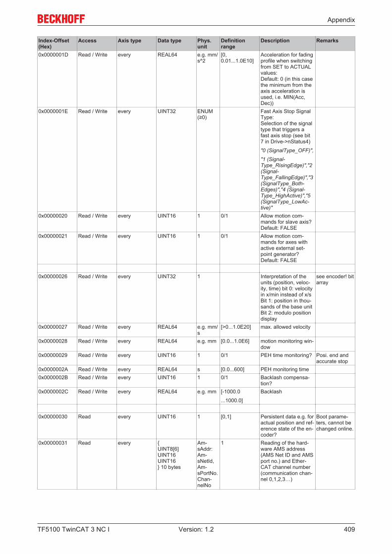
Appendix
TF5100 TwinCAT 3 NC I 409Version: 1.2
Index-Offset(Hex)
Access Axis type Data type Phys.unit
Definitionrange
Description Remarks
0x0000001D Read / Write every REAL64 e.g. mm/s^2
[0,0.01...1.0E10]
Acceleration for fadingprofile when switchingfrom SET to ACTUALvalues:Default: 0 (in this casethe minimum from theaxis acceleration isused, i.e. MIN(Acc,Dec))
0x0000001E Read / Write every UINT32 ENUM(≥0)
Fast Axis Stop SignalType:Selection of the signaltype that triggers afast axis stop (see bit7 in Drive->nStatus4)
"0 (SignalType_OFF)",
"1 (Signal-Type_RisingEdge)","2(Signal-Type_FallingEdge)","3(SignalType_Both-Edges)","4 (Signal-Type_HighActive)","5(SignalType_LowAc-tive)"
0x00000020 Read / Write every UINT16 1 0/1 Allow motion com-mands for slave axis?Default: FALSE
0x00000021 Read / Write every UINT16 1 0/1 Allow motion com-mands for axes withactive external set-point generator?Default: FALSE
0x00000026 Read / Write every UINT32 1 Interpretation of theunits (position, veloc-ity, time) bit 0: velocityin x/min instead of x/sBit 1: position in thou-sands of the base unitBit 2: modulo positiondisplay
see encoder! bitarray
0x00000027 Read / Write every REAL64 e.g. mm/s
[>0...1.0E20] max. allowed velocity
0x00000028 Read / Write every REAL64 e.g. mm [0.0...1.0E6] motion monitoring win-dow
0x00000029 Read / Write every UINT16 1 0/1 PEH time monitoring? Posi. end andaccurate stop
0x0000002A Read / Write every REAL64 s [0.0...600] PEH monitoring time0x0000002B Read / Write every UINT16 1 0/1 Backlash compensa-
tion?0x0000002C Read / Write every REAL64 e.g. mm [-1000.0
...1000.0]
Backlash
0x00000030 Read every UINT16 1 [0,1] Persistent data e.g. foractual position and ref-erence state of the en-coder?
Boot parame-ters, cannot bechanged online.
0x00000031 Read every {UINT8[6]UINT16UINT16} 10 bytes
Am-sAddr:Am-sNetId,Am-sPortNo.Chan-nelNo
1 Reading of the hard-ware AMS address(AMS Net ID and AMSport no.) and Ether-CAT channel number(communication chan-nel 0,1,2,3…)
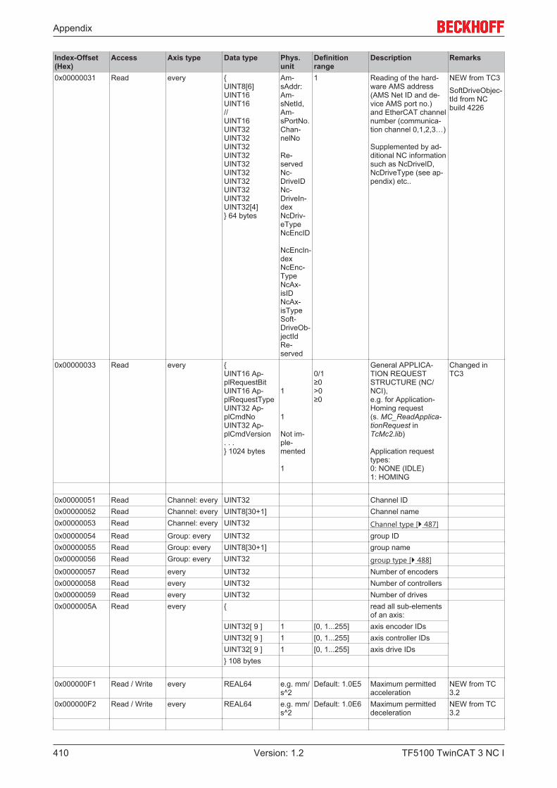
Appendix
TF5100 TwinCAT 3 NC I410 Version: 1.2
Index-Offset(Hex)
Access Axis type Data type Phys.unit
Definitionrange
Description Remarks
0x00000031 Read every {UINT8[6]UINT16UINT16//UINT16UINT32UINT32UINT32UINT32UINT32UINT32UINT32UINT32UINT32UINT32[4]} 64 bytes
Am-sAddr:Am-sNetId,Am-sPortNo.Chan-nelNo
Re-servedNc-DriveIDNc-DriveIn-dexNcDriv-eTypeNcEncID
NcEncIn-dexNcEnc-TypeNcAx-isIDNcAx-isTypeSoft-DriveOb-jectIdRe-served
1 Reading of the hard-ware AMS address(AMS Net ID and de-vice AMS port no.)and EtherCAT channelnumber (communica-tion channel 0,1,2,3…)
Supplemented by ad-ditional NC informationsuch as NcDriveID,NcDriveType (see ap-pendix) etc..
NEW from TC3
SoftDriveObjec-tId from NCbuild 4226
0x00000033 Read every {UINT16 Ap-plRequestBitUINT16 Ap-plRequestTypeUINT32 Ap-plCmdNoUINT32 Ap-plCmdVersion. . .} 1024 bytes
1
1
Not im-ple-mented
1
0/1≥0>0≥0
General APPLICA-TION REQUESTSTRUCTURE (NC/NCI),e.g. for Application-Homing request(s. MC_ReadApplica-tionRequest inTcMc2.lib)
Application requesttypes:0: NONE (IDLE)1: HOMING
Changed inTC3
0x00000051 Read Channel: every UINT32 Channel ID0x00000052 Read Channel: every UINT8[30+1] Channel name0x00000053 Read Channel: every UINT32 Channel type [} 487]0x00000054 Read Group: every UINT32 group ID0x00000055 Read Group: every UINT8[30+1] group name0x00000056 Read Group: every UINT32 group type [} 488]0x00000057 Read every UINT32 Number of encoders0x00000058 Read every UINT32 Number of controllers0x00000059 Read every UINT32 Number of drives0x0000005A Read every { read all sub-elements
of an axis:UINT32[ 9 ] 1 [0, 1...255] axis encoder IDsUINT32[ 9 ] 1 [0, 1...255] axis controller IDsUINT32[ 9 ] 1 [0, 1...255] axis drive IDs} 108 bytes
0x000000F1 Read / Write every REAL64 e.g. mm/s^2
Default: 1.0E5 Maximum permittedacceleration
NEW from TC3.2
0x000000F2 Read / Write every REAL64 e.g. mm/s^2
Default: 1.0E6 Maximum permitteddeceleration
NEW from TC3.2
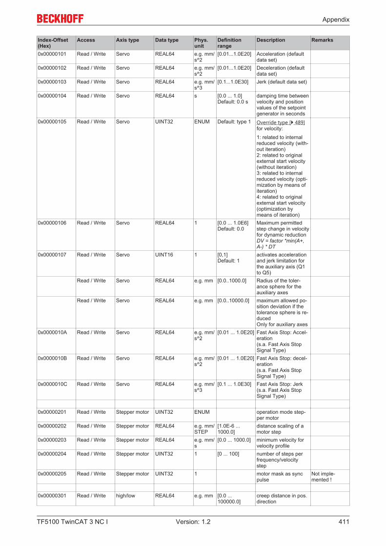
Appendix
TF5100 TwinCAT 3 NC I 411Version: 1.2
Index-Offset(Hex)
Access Axis type Data type Phys.unit
Definitionrange
Description Remarks
0x00000101 Read / Write Servo REAL64 e.g. mm/s^2
[0.01...1.0E20] Acceleration (defaultdata set)
0x00000102 Read / Write Servo REAL64 e.g. mm/s^2
[0.01...1.0E20] Deceleration (defaultdata set)
0x00000103 Read / Write Servo REAL64 e.g. mm/s^3
[0.1...1.0E30] Jerk (default data set)
0x00000104 Read / Write Servo REAL64 s [0.0 ... 1.0]Default: 0.0 s
damping time betweenvelocity and positionvalues of the setpointgenerator in seconds
0x00000105 Read / Write Servo UINT32 ENUM Default: type 1 Override type [} 489]for velocity:
1: related to internalreduced velocity (with-out iteration)2: related to originalexternal start velocity(without iteration)3: related to internalreduced velocity (opti-mization by means ofiteration)4: related to originalexternal start velocity(optimization bymeans of iteration)
0x00000106 Read / Write Servo REAL64 1 [0.0 ... 1.0E6]Default: 0.0
Maximum permittedstep change in velocityfor dynamic reductionDV = factor *min(A+,A-) * DT
0x00000107 Read / Write Servo UINT16 1 [0,1]Default: 1
activates accelerationand jerk limitation forthe auxiliary axis (Q1to Q5)
Read / Write Servo REAL64 e.g. mm [0.0..1000.0] Radius of the toler-ance sphere for theauxiliary axes
Read / Write Servo REAL64 e.g. mm [0.0..10000.0] maximum allowed po-sition deviation if thetolerance sphere is re-ducedOnly for auxiliary axes
0x0000010A Read / Write Servo REAL64 e.g. mm/s^2
[0.01 ... 1.0E20] Fast Axis Stop: Accel-eration(s.a. Fast Axis StopSignal Type)
0x0000010B Read / Write Servo REAL64 e.g. mm/s^2
[0.01 ... 1.0E20] Fast Axis Stop: decel-eration(s.a. Fast Axis StopSignal Type)
0x0000010C Read / Write Servo REAL64 e.g. mm/s^3
[0.1 ... 1.0E30] Fast Axis Stop: Jerk(s.a. Fast Axis StopSignal Type)
0x00000201 Read / Write Stepper motor UINT32 ENUM operation mode step-per motor
0x00000202 Read / Write Stepper motor REAL64 e.g. mm/STEP
[1.0E-6 ...1000.0]
distance scaling of amotor step
0x00000203 Read / Write Stepper motor REAL64 e.g. mm/s
[0.0 ... 1000.0] minimum velocity forvelocity profile
0x00000204 Read / Write Stepper motor UINT32 1 [0 ... 100] number of steps perfrequency/velocitystep
0x00000205 Read / Write Stepper motor UINT32 1 motor mask as syncpulse
Not imple-mented !
0x00000301 Read / Write high/low REAL64 e.g. mm [0.0 ...100000.0]
creep distance in pos.direction

Appendix
TF5100 TwinCAT 3 NC I412 Version: 1.2
Index-Offset(Hex)
Access Axis type Data type Phys.unit
Definitionrange
Description Remarks
0x00000302 Read / Write high/low REAL64 e.g. mm [0.0 ...100000.0]
Creep distance in neg.direction
0x00000303 Read / Write high/low REAL64 e.g. mm [0.0 ...100000.0]
braking distance inpos. direction
0x00000304 Read / Write high/low REAL64 e.g. mm [0.0 ...100000.0]
Braking distance inneg. direction
0x00000305 Read / Write high/low REAL64 s [0.0 ... 60.0] braking deceleration inpos. direction
0x00000306 Read / Write high/low REAL64 s [0.0 ... 60.0] Braking decel. in neg.direction
0x00000307 Read / Write high/low REAL64 s [0.0 ... 60.0] Switching time fromhigh to low speed
0x00000308 Read / Write high/low REAL64 e.g. mm [0.0 ...100000.0]
creep distance stop
0x00000309 Read / Write high/low REAL64 s [0.0 ... 60.0] damping time to re-lease brake
0x0000030A Read / Write high/low REAL64 s [0.0 ... 60.0] pulse time in pos. di-rection
0x0000030B Read / Write high/low REAL64 s [0.0 ... 60.0] Pulse time in neg. di-rection
ENCODER:0x00n10001 Read Encoder: every UINT32 1 [1 ... 255] Encoder ID n = 0:
Standard encoder forthe axes > 0: n-th en-coder for the axis (op-tional)
0x00n10002 Read Encoder: every UINT8[30+1] 1 30 characters encoder name0x00n10003 Read Encoder: every UINT32 1 s. ENUM (>0) encoder type [} 493]0x00n10004 Read / Write Encoder: every UINT32 1 Byteoffset Input address offset
(IO-Input-Image)change I/O ad-dress
0x00n10005 Read / Write Encoder: every UINT32 1 Byteoffset Output address offset(IO-Output-Image)
change I/O ad-dress
0x00n10006 Read / Write Encoder: every REAL64 e.g. mm/INC
[1.0E-12 ...1.0E+30]
resulting scaling factor(numerator / denomi-nator)
Note: from TC3 thescaling factor consistsof two components –numerator and de-nominator (default:1.0).
0x00n10007 Read / Write Encoder: every REAL64 e.g. mm [±1.0E+9] Position offset0x00n10008 Read / Write Encoder: every UINT16 1 [0,1] encoder count direc-
tion0x00n10009 Read / Write Encoder: every REAL64 e.g. mm [0.001 ... 1.0E
+9]modulo factor
0x00n1000A Read / Write Encoder: every UINT32 1 s. ENUM (>0) encoder mode [} 494]0x00n1000B Read / Write Encoder: every UINT16 1 0/1 soft end min. monitor-
ing?0x00n1000C Read / Write Encoder: every UINT16 1 0/1 soft end max. monitor-
ing?0x00n1000D Read / Write Encoder: every REAL64 mm soft end position min.0x00n1000E Read / Write Encoder: every REAL64 mm soft end position max.0x00n1000F Read / Write Encoder: every UINT32 1 s. ENUM (≥0)
in the appendixEncoder evaluation di-rection [} 494] (enablelog. counting direction)
0x00n10010 Read / Write Encoder: every REAL64 s [0.0...60.0] filter time for actualposition value in sec-onds (P-T1)
0x00n10011 Read / Write Encoder: every REAL64 s [0.0...60.0] filter time for actual ve-locity value in seconds(P-T1)
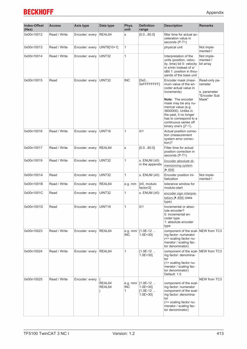
Appendix
TF5100 TwinCAT 3 NC I 413Version: 1.2
Index-Offset(Hex)
Access Axis type Data type Phys.unit
Definitionrange
Description Remarks
0x00n10012 Read / Write Encoder: every REAL64 s [0.0...60.0] filter time for actual ac-celeration value inseconds (P-T1)
0x00n10013 Read / Write Encoder: every UINT8[10+1] 1 physical unit Not imple-mented !
0x00n10014 Read / Write Encoder: every UINT32 1 Interpretation of theunits (position, veloc-ity, time) bit 0: velocityin x/min instead of x/sBit 1: position in thou-sands of the base unit
Not imple-mented !bit array
0x00n10015 Read Encoder: every UINT32 INC [0x0...0xFFFFFFFF]
Encoder mask (maxi-mum value of the en-coder actual value inincrements)
Note: The encodermask may be any nu-merical value (e.g.3600000). Unlike inthe past, it no longerhas to correspond to acontinuous series offbinary one's (2n-1).
Read-only pa-rameter
s. parameter"Encoder SubMask"
0x00n10016 Read / Write Encoder: every UINT16 1 0/1 Actual position correc-tion (measurementsystem error correc-tion)?
0x00n10017 Read / Write Encoder: every REAL64 s [0.0...60.0] Filter time for actualposition correction inseconds (P-T1)
0x00n10019 Read / Write Encoder: every UINT32 1 s. ENUM (≥0)in the appendix
Encoder absolute di-mensioning system[} 494]
0x00n1001A Read Encoder: every UINT32 1 s. ENUM (≥0) Encoder position ini-tialization
Not imple-mented !
0x00n1001B Read / Write Encoder: every REAL64 e.g. mm [≥0, modulofactor/2]
tolerance window formodulo-start
0x00n1001C Read Encoder: every UINT32 1 s. ENUM (≥0) encoder sign interpre-tation [} 494] (datatype)
0x00n1001D Read Encoder: every UINT16 1 0/1 Incremental or abso-lute encoder?0: incremental en-coder type1: absolute encodertype
0x00n10023 Read / Write Encoder: every REAL64 e.g. mm/INC
[1.0E-12 ...1.0E+30]
component of the scal-ing factor: numerator(=> scaling factor nu-merator / scaling fac-tor denominator)
NEW from TC3
0x00n10024 Read / Write Encoder: every REAL64 1 [1.0E-12 ...1.0E+30]
component of the scal-ing factor: denomina-tor(=> scaling factor nu-merator / scaling fac-tor denominator)Default: 1.0
NEW from TC3
0x00n10025 Read / Write Encoder: every {REAL64REAL64}
e.g. mm/INC1
[1.0E-12 ...1.0E+30][1.0E-12 ...1.0E+30]
component of the scal-ing factor: numeratorcomponent of the scal-ing factor: denomina-tor(=> scaling factor nu-merator / scaling fac-tor denominator)
NEW from TC3
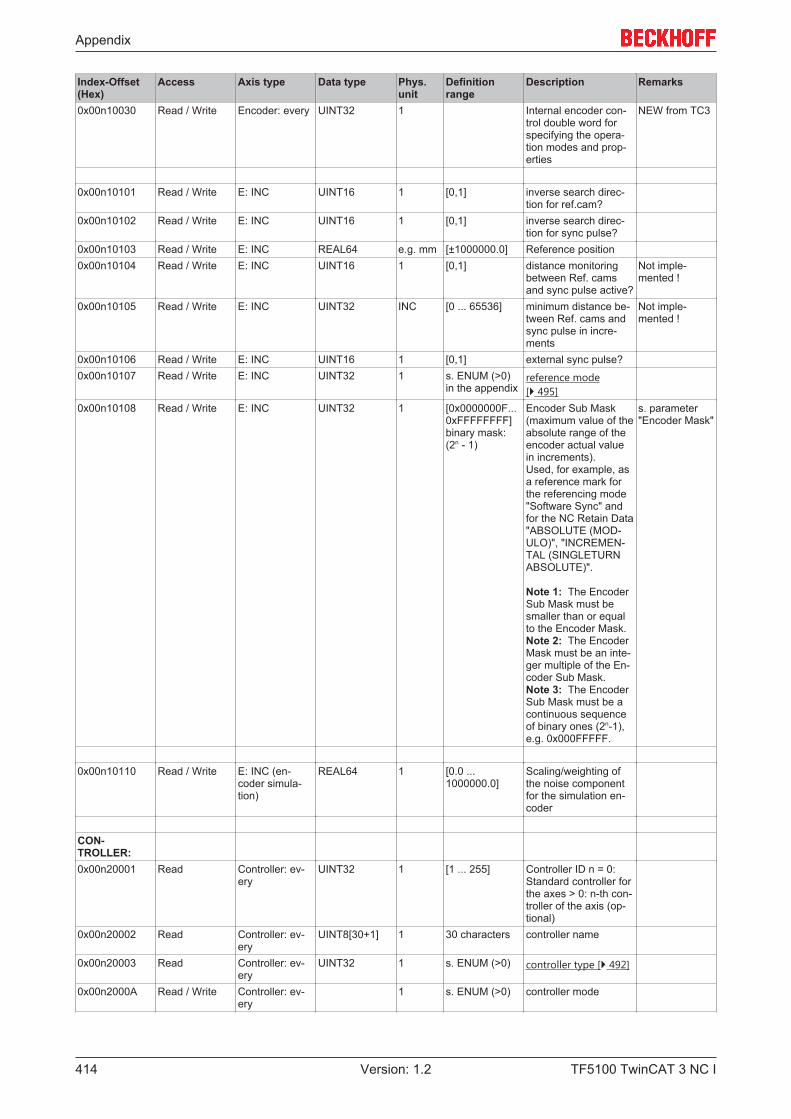
Appendix
TF5100 TwinCAT 3 NC I414 Version: 1.2
Index-Offset(Hex)
Access Axis type Data type Phys.unit
Definitionrange
Description Remarks
0x00n10030 Read / Write Encoder: every UINT32 1 Internal encoder con-trol double word forspecifying the opera-tion modes and prop-erties
NEW from TC3
0x00n10101 Read / Write E: INC UINT16 1 [0,1] inverse search direc-tion for ref.cam?
0x00n10102 Read / Write E: INC UINT16 1 [0,1] inverse search direc-tion for sync pulse?
0x00n10103 Read / Write E: INC REAL64 e.g. mm [±1000000.0] Reference position0x00n10104 Read / Write E: INC UINT16 1 [0,1] distance monitoring
between Ref. camsand sync pulse active?
Not imple-mented !
0x00n10105 Read / Write E: INC UINT32 INC [0 ... 65536] minimum distance be-tween Ref. cams andsync pulse in incre-ments
Not imple-mented !
0x00n10106 Read / Write E: INC UINT16 1 [0,1] external sync pulse?0x00n10107 Read / Write E: INC UINT32 1 s. ENUM (>0)
in the appendixreference mode[} 495]
0x00n10108 Read / Write E: INC UINT32 1 [0x0000000F...0xFFFFFFFF]binary mask:(2n - 1)
Encoder Sub Mask(maximum value of theabsolute range of theencoder actual valuein increments).Used, for example, asa reference mark forthe referencing mode"Software Sync" andfor the NC Retain Data"ABSOLUTE (MOD-ULO)", "INCREMEN-TAL (SINGLETURNABSOLUTE)".
Note 1: The EncoderSub Mask must besmaller than or equalto the Encoder Mask.Note 2: The EncoderMask must be an inte-ger multiple of the En-coder Sub Mask.Note 3: The EncoderSub Mask must be acontinuous sequenceof binary ones (2n-1),e.g. 0x000FFFFF.
s. parameter"Encoder Mask"
0x00n10110 Read / Write E: INC (en-coder simula-tion)
REAL64 1 [0.0 ...1000000.0]
Scaling/weighting ofthe noise componentfor the simulation en-coder
CON-TROLLER:0x00n20001 Read Controller: ev-
eryUINT32 1 [1 ... 255] Controller ID n = 0:
Standard controller forthe axes > 0: n-th con-troller of the axis (op-tional)
0x00n20002 Read Controller: ev-ery
UINT8[30+1] 1 30 characters controller name
0x00n20003 Read Controller: ev-ery
UINT32 1 s. ENUM (>0) controller type [} 492]
0x00n2000A Read / Write Controller: ev-ery
1 s. ENUM (>0) controller mode

Appendix
TF5100 TwinCAT 3 NC I 415Version: 1.2
Index-Offset(Hex)
Access Axis type Data type Phys.unit
Definitionrange
Description Remarks
0x00n2000B Read / Write Controller: ev-ery
REAL64 % [0.0 ... 1.0] Weighting of the ve-locity pre-control (de-fault value: 1.0 = 100%)
0x00n20010 Read / Write Controller: ev-ery
UINT16 1 0/1 following error moni-toring position?
0x00n20011 Read / Write Controller: ev-ery
UINT16 1 0/1 following error moni-toring velocity?
0x00n20012 Read / Write Controller: ev-ery
REAL64 e.g. mm max. following errorposition
0x00n20013 Read / Write Controller: ev-ery
REAL64 s max. following errortime position
0x00n20014 Read / Write Controller: ev-ery
REAL64 e.g. mm/s
max. following errorvelocity
0x00n20015 Read / Write Controller: ev-ery
REAL64 s max. following errortime velocity
0x00n20100 Read / Write P/PID (pos.,(veloc.)
REAL64 1 [0.0...1.0] Maximum output limi-tation (±) for controllertotal output
(default value:0.5 == 50%)
0x00n20102 Read / Write P/PID (pos.) REAL64 e.g. mm/s/ mm
[0.0...1000.0] Proportional gain kp orkv respectively Unit: Base Unit / s /Base Unit
position control
0x00n20103 Read / Write PID (pos.) REAL64 s [0.0 ... 60.0] Integral action time Tn position control0x00n20104 Read / Write PID (pos.) REAL64 s [0.0 ... 60.0] Derivative action time
Tvposition control
0x00n20105 Read / Write PID (pos.) REAL64 s [0.0 ... 60.0] Damping time Td position control0x00n20106 Read / Write PP (Pos.) REAL64 e.g. mm/
s/ mm[0.0...1000.0] Additional proportional
gain, kp or kv respec-tively, that appliesabove a limit velocityin percent.Unit: Base Unit / s /Base Unit
position control
0x00n20107 Read / Write PP (Pos.) REAL64 % [0.0...1.0] Threshold velocity inpercent above whichthe additional propor-tional gain, kp or kv re-spectively, applies
0x00n20108 Read / Write P/PID (Acc.) REAL64 s [0.0 ... 100.0] Proportional gain ka accelerationpre-control
0x00n2010D Read / Write P/PID REAL64 mm [0.0 ... 10000.0] "dead band" for posi-tion error (control devi-ation)(for P/PID controllerswith velocity or torqueinterface)
reserved func-tion
0x00n2010F Read / Write P/PP/PID(Pos.)slave control
REAL64 (mm/s) /mm
[0.0...1000.0] Slave coupling differ-ence control:proportional gain kcp
Slave couplingdifference con-trol:
0x00n20110 Read / Write P (Pos.) UINT16 1 0/1 Automatic offset cali-bration: active/passive
0x00n20111 Read / Write P (Pos.) UINT16 1 0/1 Automatic offset cali-bration: hold mode
0x00n20112 Read / Write P (Pos.) UINT16 1 0/1 Automatic offset cali-bration: fading mode
0x00n20114 Read / Write P (Pos.) REAL64 % [0.0 ... 1.0] Automatic offset cali-bration: pre-controllimit
0x00n20115 Read / Write P (Pos.) REAL64 s [0.1 ... 60.0] Automatic offset cali-bration: time constant
0x00n20116 Read / Write PID (pos.) REAL64 % [0.0...1.0] Maximum output limi-tation (±) for I-part inpercent (default set-ting: 0.1 = 10%)
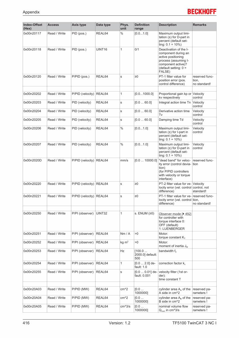
Appendix
TF5100 TwinCAT 3 NC I416 Version: 1.2
Index-Offset(Hex)
Access Axis type Data type Phys.unit
Definitionrange
Description Remarks
0x00n20117 Read / Write PID (pos.) REAL64 % [0.0...1.0] Maximum output limi-tation (±) for D-part inpercent (default set-ting: 0.1 = 10%)
0x00n20118 Read / Write PID (pos.) UINT16 1 0/1 Deactivation of the I-component during anactive positioningprocess (assuming I-component active)?(default setting: 0 =FALSE)
0x00n20120 Read / Write P/PID (pos.) REAL64 s ≥0 PT-1 filter value forposition error (pos.control difference)
reserved func-tion,no standard!
0x00n20202 Read / Write P/PID (velocity) REAL64 1 [0.0...1000.0] Proportional gain kp orkv respectively
Velocity control
0x00n20203 Read / Write PID (velocity) REAL64 s [0.0 ... 60.0] Integral action time Tn Velocity control
0x00n20204 Read / Write PID (velocity) REAL64 s [0.0 ... 60.0] Derivative action timeTv
Velocity control
0x00n20205 Read / Write PID (velocity) REAL64 s [0.0 ... 60.0] Damping time Td Velocity control
0x00n20206 Read / Write PID (velocity) REAL64 % [0.0...1.0] Maximum output limi-tation (±) for I-part inpercent (default set-ting: 0.1 = 10%)
Velocity control
0x00n20207 Read / Write PID (velocity) REAL64 % [0.0...1.0] Maximum output limi-tation (±) for D-part inpercent (default set-ting: 0.1 = 10%)
Velocity control
0x00n2020D Read / Write P/PID (velocity) REAL64 mm/s [0.0 ... 10000.0] "dead band" for veloc-ity error (control devia-tion)(for P/PID controllerswith velocity or torqueinterface)
reserved func-tion
0x00n20220 Read / Write P/PID (velocity) REAL64 s ≥0 PT-2 filter value for ve-locity error (vel. controldifference)
Velocity control, notstandard!
0x00n20221 Read / Write P/PID (velocity) REAL64 s ≥0 PT-1 filter value for ve-locity error (vel. controldifference)
reserved func-tion,no standard!
0x00n20250 Read / Write P/PI (observer) UINT32 1 s. ENUM (≥0) Observer mode [} 492]for controller withtorque interface 0:OFF (default)1: LUENBERGER
0x00n20251 Read / Write P/PI (observer) REAL64 Nm / A >0 Motor:torque constant KT
0x00n20252 Read / Write P/PI (observer) REAL64 kg m2 >0 Motor:moment of inertia JM
0x00n20253 Read / Write P/PI (observer) REAL64 Hz [100.0 ...2000.0] default:500
bandwidth f0
0x00n20254 Read / Write P/PI (observer) REAL64 1 [0.0 ... 2.0] de-fault: 1.0
correction factor kc
0x00n20255 Read / Write P/PI (observer) REAL64 s [0.0 ... 0.01] de-fault: 0.001
velocity filter (1st or-der):time constant T
0x00n20A03 Read / Write P/PID (MW) REAL64 cm^2 [0.0 ...1000000]
cylinder area AA of theA side in cm^2
reserved pa-rameters !
0x00n20A04 Read / Write P/PID (MW) REAL64 cm^2 [0.0 ...1000000]
cylinder area AB of theB side in cm^2
reserved pa-rameters !
0x00n20A05 Read / Write P/PID (MW) REAL64 cm^3/s [0.0 ...1000000]
nominal volume flowQnom in cm^3/s
reserved pa-rameters !
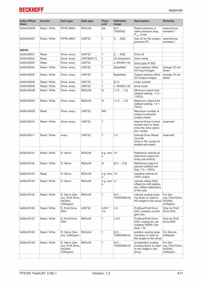
Appendix
TF5100 TwinCAT 3 NC I 417Version: 1.2
Index-Offset(Hex)
Access Axis type Data type Phys.unit
Definitionrange
Description Remarks
0x00n20A06 Read / Write P/PID (MW) REAL64 bar [0.0 ...1000000]
Rated pressure orvalve pressure drop,Pnom in bar
reserved pa-rameters !
0x00n20A07 Read / Write P/PID (MW) UINT32 1 [1 ... 255] Axis ID for the systempressure Po
reserved pa-rameters !
DRIVE:0x00n30001 Read Drive: every UINT32 1 [1 ... 255] Drive ID0x00n30002 Read Drive: every UINT8[30+1] 1 30 characters Drive name0x00n30003 Read Drive: every UINT32 1 s. ENUM (>0) Drive type [} 496]0x00n30004 Read / Write Drive: every UINT32 1 Byteoffset Input address offset
(IO-Input-Image)change I/O ad-dress
0x00n30005 Read / Write Drive: every UINT32 1 Byteoffset Output address offset(IO-Output-Image)
change I/O ad-dress
0x00n30006 Read / Write Drive: every UINT16 1 [0,1] motor polarity0x00n3000A Read / Write Drive: every UINT32 1 s. ENUM (>0) drive mode0x00n3000B Read / Write Drive: every REAL64 % [-1.0 ... 1.0] Minimum output limit
(default setting: -1.0 =-100%)
0x00n3000C Read / Write Drive: every REAL64 % [-1.0 ... 1.0] Maximum output limit(default setting: 1.0 =100%)
0x00n3000D Read Drive: every UINT32 INC Maximum number ofoutput increments(output mask)
0x00n30010 Read / Write Drive: every UINT32 1 Internal Drive Controldouble word to deter-mine the drive opera-tion modes
reserved!
0x00n30011 Read / Write every UINT32 1 ≥ 5 Internal Drive ResetCounter(time in NC cycles forenable and reset)
reserved!
0x00n30101 Read / Write D: Servo REAL64 e.g. mm/s
>0 Reference velocity atreference output (ve-locity pre-control)
0x00n30102 Read / Write D: Servo REAL64 % [0.0 ... 5.0] Reference output inpercent (default set-ting: 1.0 = 100%)
0x00n30103 Read D: Servo REAL64 e.g. mm/s
>0 resulting velocity at100% output
0x00n30104 Read / Write D: Servo REAL64 e.g. mm/s
±∞ velocity offset (DACoffset) for drift calibra-tion (offset calibration)of the axis
0x00n30105 Read / Write D: Servo (Ser-cos, Profi Drive,AX200x,CANopen)
REAL64 1 [0.0 ...100000000.0]
velocity scaling (scal-ing factor to react tothe weight in the drive)
For Ser-cos, Profi Drive,AX200x,CANopen
0x00n30106 Read / Write D: Profi DriveDSC
UINT32 0.001 *1/s
≥ 0 Profibus/Profi DriveDSC: position controlgain Kpc
Only for ProfiDrive DSC
0x00n30107 Read / Write D: Profi DriveDSC
REAL64 1 ≥ 0.0 Profibus/Profi DriveDSC: scaling for cal-culating 'XERR' (De-fault: 1.0)
Only for ProfiDrive DSC
0x00n30109 Read / Write D: Servo (Ser-cos, CANopen)
REAL64 1 [0.0 ...100000000.0]
position scaling (scal-ing factor to react tothe weight in the drive)
For Sercos,CANopen
0x00n3010A Read / Write D: Servo (Ser-cos, Profi Drive,AX200x,CANopen)
REAL64 1 [0.0 ...100000000.0]
acceleration scaling(scaling factor to reactto the weight in thedrive)
For Ser-cos, Profi Drive,AX200x,CANopen
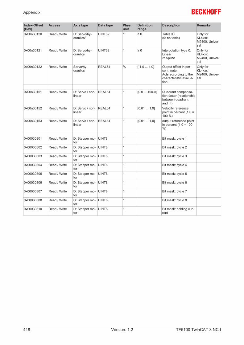
Appendix
TF5100 TwinCAT 3 NC I418 Version: 1.2
Index-Offset(Hex)
Access Axis type Data type Phys.unit
Definitionrange
Description Remarks
0x00n30120 Read / Write D: Servo/hy-draulics/
UINT32 1 ≥ 0 Table ID(0: no table)
Only forKL4xxx,M2400, Univer-sal
0x00n30121 Read / Write D: Servo/hy-draulics
UINT32 1 ≥ 0 Interpolation type 0:Linear2: Spline
Only forKL4xxx,M2400, Univer-sal
0x00n30122 Read / Write Servo/hy-draulics
REAL64 % [-1.0 ... 1.0] Output offset in per-cent, note:Acts according to thecharacteristic evalua-tion !
Only forKL4xxx,M2400, Univer-sal
0x00n30151 Read / Write D: Servo / non-linear
REAL64 1 [0.0 ... 100.0] Quadrant compensa-tion factor (relationshipbetween quadrant Iand III)
0x00n30152 Read / Write D: Servo / non-linear
REAL64 1 [0.01 ... 1.0] Velocity referencepoint in percent (1.0 =100 %)
0x00n30153 Read / Write D: Servo / non-linear
REAL64 1 [0.01 ... 1.0] output reference pointin percent (1.0 = 100%)
0x00030301 Read / Write D: Stepper mo-tor
UINT8 1 Bit mask: cycle 1
0x00030302 Read / Write D: Stepper mo-tor
UINT8 1 Bit mask: cycle 2
0x00030303 Read / Write D: Stepper mo-tor
UINT8 1 Bit mask: cycle 3
0x00030304 Read / Write D: Stepper mo-tor
UINT8 1 Bit mask: cycle 4
0x00030305 Read / Write D: Stepper mo-tor
UINT8 1 Bit mask: cycle 5
0x00030306 Read / Write D: Stepper mo-tor
UINT8 1 Bit mask: cycle 6
0x00030307 Read / Write D: Stepper mo-tor
UINT8 1 Bit mask: cycle 7
0x00030308 Read / Write D: Stepper mo-tor
UINT8 1 Bit mask: cycle 8
0x00030310 Read / Write D: Stepper mo-tor
UINT8 1 Bit mask: holding cur-rent

Appendix
TF5100 TwinCAT 3 NC I 419Version: 1.2
7.8.4.2 "Index offset" specification for Axis state (Index group 0x4100 + ID)
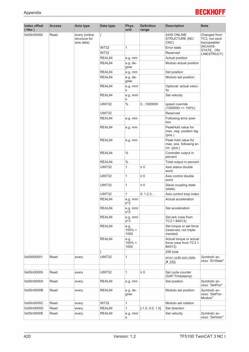
Appendix
TF5100 TwinCAT 3 NC I420 Version: 1.2
Index offset( Hex )
Access Axis type Data type Phys.unit
Definitionrange
Description Note
0x00n00000 Read every (onlinestructure foraxis data)
{ AXIS ONLINESTRUCTURE (NC/CNC)
Changed fromTC3, not oscil-loscopeable!(NCAXIS-STATE_ ON-LINESTRUCT)
INT32 1 Error stateINT32 ReservedREAL64 e.g. mm Actual positionREAL64 e.g. de-
greeModulo actual position
REAL64 e.g. mm Set positionREAL64 e.g. de-
greeModulo set position
REAL64 e.g. mm/s
Optional: actual veloc-ity
REAL64 e.g. mm/s
Set velocity
UINT32 % 0...1000000 speed override(1000000 == 100%)
UINT32 ReservedREAL64 e.g. mm Following error posi-
tionREAL64 e.g. mm PeakHold value for
max. neg. position lag(pos.)
REAL64 e.g. mm Peak hold value formax. pos. following er-ror. (pos.)
REAL64 % Controller output inpercent
REAL64 % Total output in percentUINT32 1 ≥ 0 Axis status double
wordUINT32 1 ≥ 0 Axis control double
wordUINT32 1 ≥ 0 Slave coupling state
(state)UINT32 1 0; 1,2,3... Axis control loop indexREAL64 e.g. mm/
s^2Actual acceleration
REAL64 e.g. mm/s^2
Set acceleration
REAL64 e.g. mm/s^3
Set jerk (new fromTC3.1 B4013)
REAL64 e.g.100% =1000
Set torque or set force(reserved, not imple-mented)
REAL64 e.g.100% =1000
Actual torque or actualforce (new from TC3.1B4013)
} 256 byte0x00000001 Read every UINT32 1 error code axis state
[} 340]Symbolic ac-cess: 'ErrState''
0x00n00009 Read every UINT32 1 ≥ 0 Set cycle counter(SAF-Timestamp)
0x00n0000A Read every REAL64 e.g. mm Set position Symbolic ac-cess: 'SetPos''
0x00n0000B Read every REAL64 e.g. de-gree
Modulo set position Symbolic ac-cess: 'SetPos-Modulo''
0x00n0000C Read every INT32 1 Modulo set rotation0x00n0000D Read every REAL64 1 [-1.0, 0.0, 1.0] Set direction0x00n0000E Read every REAL64 e.g. mm/
sSet velocity Symbolic ac-
cess: 'SetVelo''
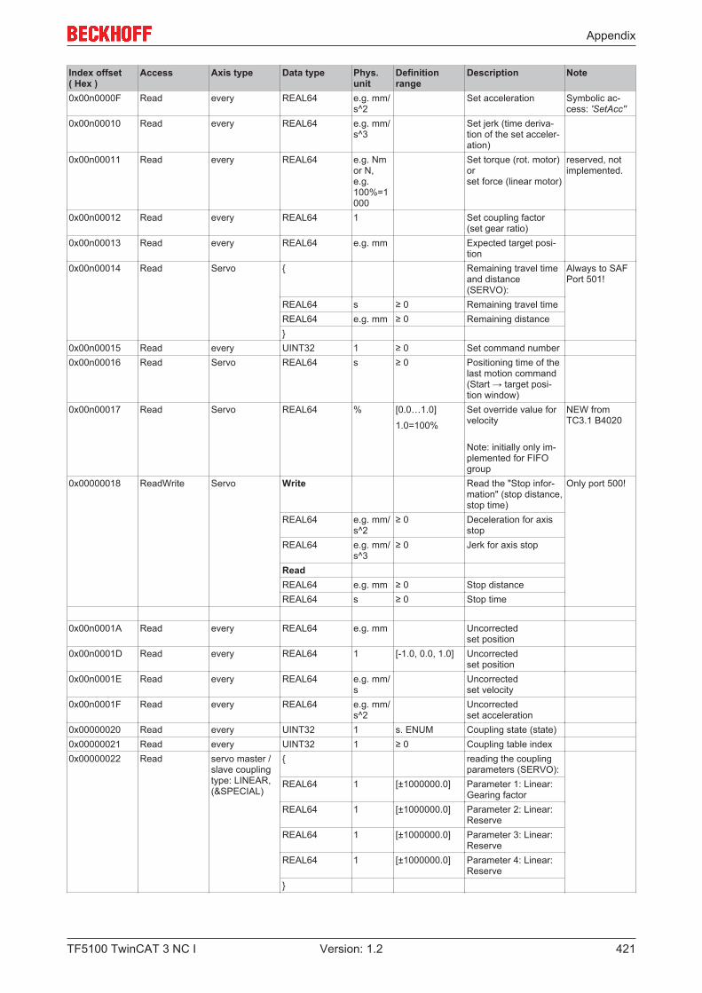
Appendix
TF5100 TwinCAT 3 NC I 421Version: 1.2
Index offset( Hex )
Access Axis type Data type Phys.unit
Definitionrange
Description Note
0x00n0000F Read every REAL64 e.g. mm/s^2
Set acceleration Symbolic ac-cess: 'SetAcc''
0x00n00010 Read every REAL64 e.g. mm/s^3
Set jerk (time deriva-tion of the set acceler-ation)
0x00n00011 Read every REAL64 e.g. Nmor N, e.g.100%=1000
Set torque (rot. motor)or set force (linear motor)
reserved, notimplemented.
0x00n00012 Read every REAL64 1 Set coupling factor(set gear ratio)
0x00n00013 Read every REAL64 e.g. mm Expected target posi-tion
0x00n00014 Read Servo { Remaining travel timeand distance(SERVO):
Always to SAFPort 501!
REAL64 s ≥ 0 Remaining travel timeREAL64 e.g. mm ≥ 0 Remaining distance}
0x00n00015 Read every UINT32 1 ≥ 0 Set command number0x00n00016 Read Servo REAL64 s ≥ 0 Positioning time of the
last motion command(Start → target posi-tion window)
0x00n00017 Read Servo REAL64 % [0.0…1.0]
1.0=100%
Set override value forvelocity
Note: initially only im-plemented for FIFOgroup
NEW fromTC3.1 B4020
0x00000018 ReadWrite Servo Write Read the "Stop infor-mation" (stop distance,stop time)
Only port 500!
REAL64 e.g. mm/s^2
≥ 0 Deceleration for axisstop
REAL64 e.g. mm/s^3
≥ 0 Jerk for axis stop
ReadREAL64 e.g. mm ≥ 0 Stop distanceREAL64 s ≥ 0 Stop time
0x00n0001A Read every REAL64 e.g. mm Uncorrectedset position
0x00n0001D Read every REAL64 1 [-1.0, 0.0, 1.0] Uncorrectedset position
0x00n0001E Read every REAL64 e.g. mm/s
Uncorrected set velocity
0x00n0001F Read every REAL64 e.g. mm/s^2
Uncorrected set acceleration
0x00000020 Read every UINT32 1 s. ENUM Coupling state (state)0x00000021 Read every UINT32 1 ≥ 0 Coupling table index0x00000022 Read servo master /
slave couplingtype: LINEAR,(&SPECIAL)
{ reading the couplingparameters (SERVO):
REAL64 1 [±1000000.0] Parameter 1: Linear:Gearing factor
REAL64 1 [±1000000.0] Parameter 2: Linear:Reserve
REAL64 1 [±1000000.0] Parameter 3: Linear:Reserve
REAL64 1 [±1000000.0] Parameter 4: Linear:Reserve
}
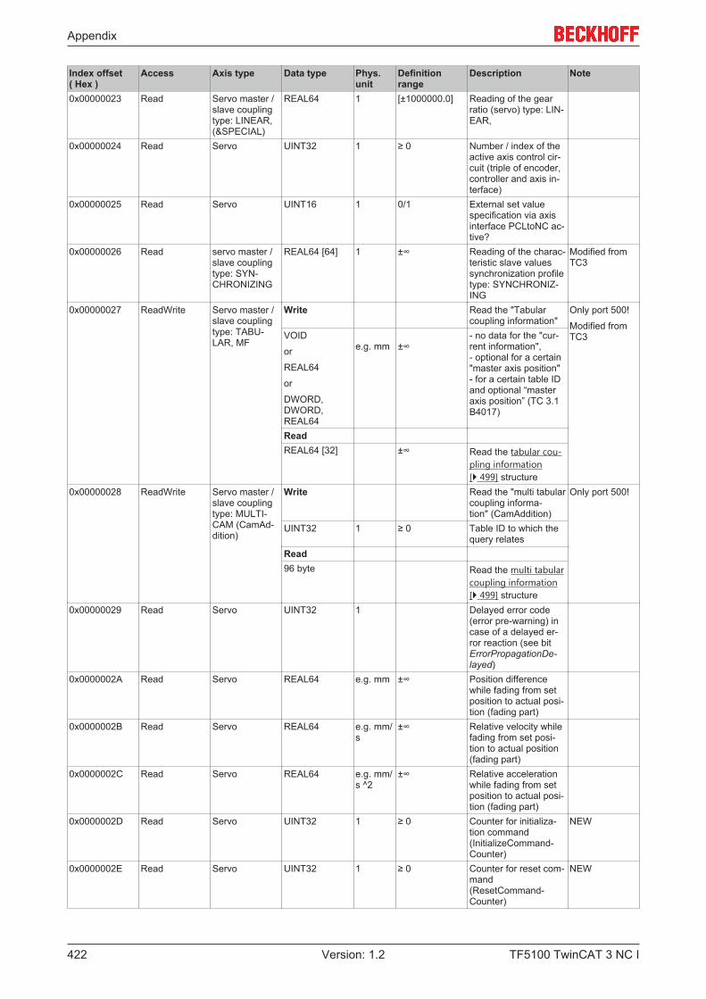
Appendix
TF5100 TwinCAT 3 NC I422 Version: 1.2
Index offset( Hex )
Access Axis type Data type Phys.unit
Definitionrange
Description Note
0x00000023 Read Servo master /slave couplingtype: LINEAR,(&SPECIAL)
REAL64 1 [±1000000.0] Reading of the gearratio (servo) type: LIN-EAR,
0x00000024 Read Servo UINT32 1 ≥ 0 Number / index of theactive axis control cir-cuit (triple of encoder,controller and axis in-terface)
0x00000025 Read Servo UINT16 1 0/1 External set valuespecification via axisinterface PCLtoNC ac-tive?
0x00000026 Read servo master /slave couplingtype: SYN-CHRONIZING
REAL64 [64] 1 ±∞ Reading of the charac-teristic slave valuessynchronization profiletype: SYNCHRONIZ-ING
Modified fromTC3
0x00000027 ReadWrite Servo master /slave couplingtype: TABU-LAR, MF
Write Read the "Tabularcoupling information"
Only port 500!
Modified fromTC3VOID
or
REAL64
or
DWORD,DWORD,REAL64
e.g. mm ±∞- no data for the "cur-rent information",- optional for a certain"master axis position"- for a certain table IDand optional “masteraxis position” (TC 3.1B4017)
ReadREAL64 [32] ±∞ Read the tabular cou-
pling information[} 499] structure
0x00000028 ReadWrite Servo master /slave couplingtype: MULTI-CAM (CamAd-dition)
Write Read the "multi tabularcoupling informa-tion" (CamAddition)
Only port 500!
UINT32 1 ≥ 0 Table ID to which thequery relates
Read96 byte Read the multi tabular
coupling information[} 499] structure
0x00000029 Read Servo UINT32 1 Delayed error code(error pre-warning) incase of a delayed er-ror reaction (see bitErrorPropagationDe-layed)
0x0000002A Read Servo REAL64 e.g. mm ±∞ Position differencewhile fading from setposition to actual posi-tion (fading part)
0x0000002B Read Servo REAL64 e.g. mm/s
±∞ Relative velocity whilefading from set posi-tion to actual position(fading part)
0x0000002C Read Servo REAL64 e.g. mm/s ^2
±∞ Relative accelerationwhile fading from setposition to actual posi-tion (fading part)
0x0000002D Read Servo UINT32 1 ≥ 0 Counter for initializa-tion command(InitializeCommand-Counter)
NEW
0x0000002E Read Servo UINT32 1 ≥ 0 Counter for reset com-mand(ResetCommand-Counter)
NEW
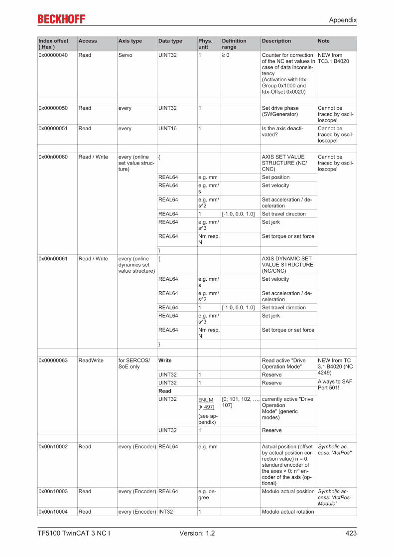
Appendix
TF5100 TwinCAT 3 NC I 423Version: 1.2
Index offset( Hex )
Access Axis type Data type Phys.unit
Definitionrange
Description Note
0x00000040 Read Servo UINT32 1 ≥ 0 Counter for correctionof the NC set values incase of data inconsis-tency (Activation with Idx-Group 0x1000 andIdx-Offset 0x0020)
NEW fromTC3.1 B4020
0x00000050 Read every UINT32 1 Set drive phase(SWGenerator)
Cannot betraced by oscil-loscope!
0x00000051 Read every UINT16 1 Is the axis deacti-vated?
Cannot betraced by oscil-loscope!
0x00n00060 Read / Write every (onlineset value struc-ture)
{ AXIS SET VALUESTRUCTURE (NC/CNC)
Cannot betraced by oscil-loscope!
REAL64 e.g. mm Set positionREAL64 e.g. mm/
sSet velocity
REAL64 e.g. mm/s^2
Set acceleration / de-celeration
REAL64 1 [-1.0, 0.0, 1.0] Set travel directionREAL64 e.g. mm/
s^3Set jerk
REAL64 Nm resp.N
Set torque or set force
}0x00n00061 Read / Write every (online
dynamics setvalue structure)
{ AXIS DYNAMIC SETVALUE STRUCTURE(NC/CNC)
REAL64 e.g. mm/s
Set velocity
REAL64 e.g. mm/s^2
Set acceleration / de-celeration
REAL64 1 [-1.0, 0.0, 1.0] Set travel directionREAL64 e.g. mm/
s^3Set jerk
REAL64 Nm resp.N
Set torque or set force
}
0x00000063 ReadWrite for SERCOS/SoE only
Write Read active "DriveOperation Mode"
NEW from TC3.1 B4020 (NC4249)
Always to SAFPort 501!
UINT32 1 ReserveUINT32 1 ReserveReadUINT32 ENUM
[} 497]
(see ap-pendix)
[0; 101, 102, …,107]
currently active "DriveOperationMode" (genericmodes)
UINT32 1 Reserve
0x00n10002 Read every (Encoder) REAL64 e.g. mm Actual position (offsetby actual position cor-rection value) n = 0:standard encoder ofthe axes > 0: nth en-coder of the axis (op-tional)
Symbolic ac-cess: 'ActPos''
0x00n10003 Read every (Encoder) REAL64 e.g. de-gree
Modulo actual position Symbolic ac-cess: 'ActPos-Modulo'
0x00n10004 Read every (Encoder) INT32 1 Modulo actual rotation

Appendix
TF5100 TwinCAT 3 NC I424 Version: 1.2
Index offset( Hex )
Access Axis type Data type Phys.unit
Definitionrange
Description Note
0x00n10005 Read every (Encoder) REAL64 e.g. mm/s
Optional: actual veloc-ity
Symbolic ac-cess: 'ActVelo''
0x00n10006 Read every (Encoder) REAL64 e.g. mm/s^2
Optional: Actual accel-eration
Symbolic ac-cess: 'ActAcc''
0x00n10007 Read every (Encoder) INT32 INC Encoder actual incre-ments
0x00n10008 Read every (Encoder) INT64 INC Software - actual in-crement counter
0x00n10009 Read every (Encoder) UINT16 1 0/1 Reference flag ("cali-brate flag")
0x00n1000A Read every (Encoder) REAL64 e.g. mm Actual position correc-tion value (measure-ment system error cor-rection)
0x00n1000B Read every (Encoder) REAL64 e.g. mm Actual position withoutactual position com-pensation value
Cannot betraced by oscil-loscope!
0x00n10010 Read every (Encoder) REAL64 e.g. mm/s
Actual velocity withoutactual position com-pensation value
0x00n10012 Read every (Encoder) REAL64 e.g. mm Unfiltered actual posi-tion (charge with ac-tual position compen-sation value)
0x00n10014 Read Encoder: SoE,CoE, MDP 742
REAL64 e.g. mm/s
Optional: Actual drivevelocity (transferreddirectly from SoE, CoEor MDP 742 drive)
NEW fromTC3.1B4020.30
0x00n10015 Read every (Encoder) REAL64 e.g. mm/s
Optional: Unfilteredactual velocity
0x00n10101 Read INC (Encoder) REAL64 e.g. mm Read back of the posi-tion difference be-tween activation of theinternal hardware latchand the time when itbecomes valid
Cannot betraced by oscil-loscope!
0x00n20001 Read R: every INT32 1 Error state of the con-troller n = 0: standardcontroller of the axes >0: nth controller of theaxis (optional)
0x00n20002 Read R: every REAL64 e.g. mm/s
Controller output inabsolute units
Symbolic ac-cess: 'CtrlOut-put''
0x00n20003 Read R: every REAL64 % Controller output inpercent
Cannot betraced by oscil-loscope!
0x00n20004 Read R: every REAL64 V Controller output involts
Cannot betraced by oscil-loscope!
0x00n2000D Read R: every REAL64 e.g. mm Following error posi-tion (without dead timecompensation)
Base Unit
0x00n2000F Read R: every REAL64 e.g. mm Following error posi-tion (with dead timecompensation)
Symbolic ac-cess: 'PosDiff''
0x00n20010 Read R: every REAL64 e.g. mm Peak hold value formaximum negative fol-lowing error of the po-sition
0x00n20011 Read R: every REAL64 e.g. mm Peak hold value forminimum positive fol-lowing error of the po-sition

Appendix
TF5100 TwinCAT 3 NC I 425Version: 1.2
Index offset( Hex )
Access Axis type Data type Phys.unit
Definitionrange
Description Note
0x00n20012 Read R: every REAL64 e.g. mm/s
Following error veloc-ity
Not imple-mented !
0x00n20021 Read R: every REAL64 e.g. mm Difference (deviation)between the followingerror from master andslave axis (master er-ror minus slave error)
Symbolic ac-cess: 'PosDiff-Couple'
0x00n20022 Read R: every REAL64 e.g. mm PeakHold value for themaximum negative dif-ference between mas-ter and slave axis fol-lowing error of the po-sition
Base Unit
0x00n20023 Read R: every REAL64 e.g. mm PeakHold value for themaximum positive dif-ference between mas-ter and slave axis fol-lowing error of the po-sition
Base Unit
0x00n20101 Read R: P/PID (pos.) REAL64 e.g. mm/s
Proportional compo-nent of the controllerin absolute units
0x00n20102 Read R: PID (pos.) REAL64 e.g. mm/s
I-part of the controllerin absolute units
0x00n20103 Read R: PID (pos.) REAL64 e.g. mm/s
D-part of the controllerin absolute units
0x00n20104 Read R: PID (pos.) UINT16 1 0/1 Limitation of the I-partactive?
0x00n20105 Read R: PID (pos.) UINT16 1 0/1 Limitation of the D-partactive?
0x00n20106 Read R: PID (pos.) UINT16 1 0/1 ARW measures of theI component active?ARW: Anti ResetWindup
Not imple-mented !
0x00n20110 Read R: PID (pos.) REAL64 e.g. mm/s
Acceleration pre-con-trol Yacc of the con-troller in absoluteunits, note: Functiondepends on controllertype!
Accelerationpre-control
0x00n20111 Read R: PP (Pos.) REAL64 mm/s/mm
≥0 Internal interpolatedproportional gain kp orkv
PP controller
0x00n20201 Read R: P,PID (ve-locity)
REAL64 e.g. mm/s
Velocity part of thecontroller
0x00n20202 Read R: P,PID (ve-locity)
REAL64 % Velocity part of thecontroller in percent
Cannot betraced by oscil-loscope!
0x00n20203 Read R: P,PID (ve-locity)
REAL64 V Velocity part of thecontroller in volts
Cannot betraced by oscil-loscope!
0x00n20201 Read R: P/PID (ve-locity)
REAL64 e.g. mm/s
Proportional compo-nent of the controllerin absolute units
0x00n20202 Read R: P/ PID (ve-loc.)
REAL64 e.g. mm/s
I-part of the controllerin absolute units
0x00n20203 Read R: P/ PID (ve-loc.)
REAL64 e.g. mm/s
D-part of the controllerin absolute units
0x00n20204 Read R: P/ PID (ve-loc.)
UINT16 1 0/1 Limitation of the I-partactive?
0x00n20205 Read R: P/ PID (ve-loc.)
UINT16 1 0/1 Limitation of the D-partactive?
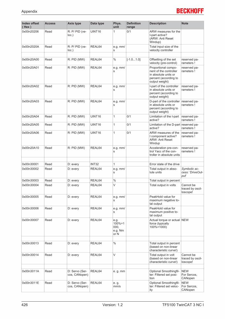
Appendix
TF5100 TwinCAT 3 NC I426 Version: 1.2
Index offset( Hex )
Access Axis type Data type Phys.unit
Definitionrange
Description Note
0x00n20206 Read R: P/ PID (ve-loc.)
UINT16 1 0/1 ARW measures for theI-part active? (ARW: Anti ResetWindup)
0x00n2020A Read R: P/ PID (ve-loc.)
REAL64 e.g. mm/s
Total input size of thevelocity controller
0x00n20A00 Read R: PID (MW) REAL64 % [-1.0...1.0] Offsetting of the setvelocity (pre-control)
reserved pa-rameters !
0x00n20A01 Read R: PID (MW) REAL64 e.g. mm/s
Proportional compo-nent of the controllerin absolute units orpercent (according tooutput weight)
reserved pa-rameters !
0x00n20A02 Read R: PID (MW) REAL64 e.g. mm/s
I-part of the controllerin absolute units orpercent (according tooutput weight)
reserved pa-rameters !
0x00n20A03 Read R: PID (MW) REAL64 e.g. mm/s
D-part of the controllerin absolute units orpercent (according tooutput weight)
reserved pa-rameters !
0x00n20A04 Read R: PID (MW) UINT16 1 0/1 Limitation of the I-partactive?
reserved pa-rameters !
0x00n20A05 Read R: PID (MW) UINT16 1 0/1 Limitation of the D-partactive?
reserved pa-rameters !
0x00n20A06 Read R: PID (MW) UINT16 1 0/1 ARW measures of theI component active?ARW: Anti ResetWindup
reserved pa-rameters !
0x00n20A10 Read R: PID (MW) REAL64 e.g. mm/s
Acceleration pre-con-trol Yacc of the con-troller in absolute units
reserved pa-rameters !
0x00n30001 Read D: every INT32 1 Error state of the drive0x00n30002 Read D: every REAL64 e.g. mm/
sTotal output in abso-lute units
Symbolic ac-cess: 'DriveOut-put'
0x00n30003 Read D: every REAL64 % Total output in percent0x00n30004 Read D: every REAL64 V Total output in volts Cannot be
traced by oscil-loscope!
0x00n30005 Read D: every REAL64 e.g. mm/s
PeakHold value formaximum negative to-tal output
0x00n30006 Read D: every REAL64 e.g. mm/s
PeakHold value formaximum positive to-tal output
0x00n30007 Read D: every REAL64 e.g.100%=1000, e.g. Nmor N
Actual torque or actualforce (typically100%=1000)
NEW
0x00n30013 Read D: every REAL64 % Total output in percent(based on non-linearcharacteristic curve!)
0x00n30014 Read D: every REAL64 V Total output in volt(based on non-linearcharacteristic curve!)
Cannot betraced by oscil-loscope!
0x00n3011A Read D: Servo (Ser-cos, CANopen)
REAL64 e. g. mm Optional Smoothingfil-ter: Filtered set posi-tion
NEWFor Sercos,CANopen
0x00n3011E Read D: Servo (Ser-cos, CANopen)
REAL64 e. g.mm/s
Optional Smoothingfil-ter: Filtered set veloc-ity
NEWFor Sercos,CANopen
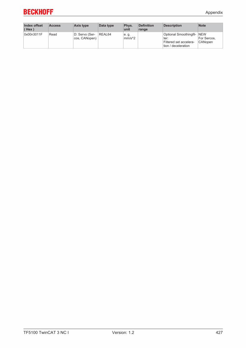
Appendix
TF5100 TwinCAT 3 NC I 427Version: 1.2
Index offset( Hex )
Access Axis type Data type Phys.unit
Definitionrange
Description Note
0x00n3011F Read D: Servo (Ser-cos, CANopen)
REAL64 e. g.mm/s^2
Optional Smoothingfil-ter:Filtered set accelera-tion / deceleration
NEWFor Sercos,CANopen

Appendix
TF5100 TwinCAT 3 NC I428 Version: 1.2
7.8.4.3 "Index offset" specification for Axis functions (Index group 0x4200 + ID)
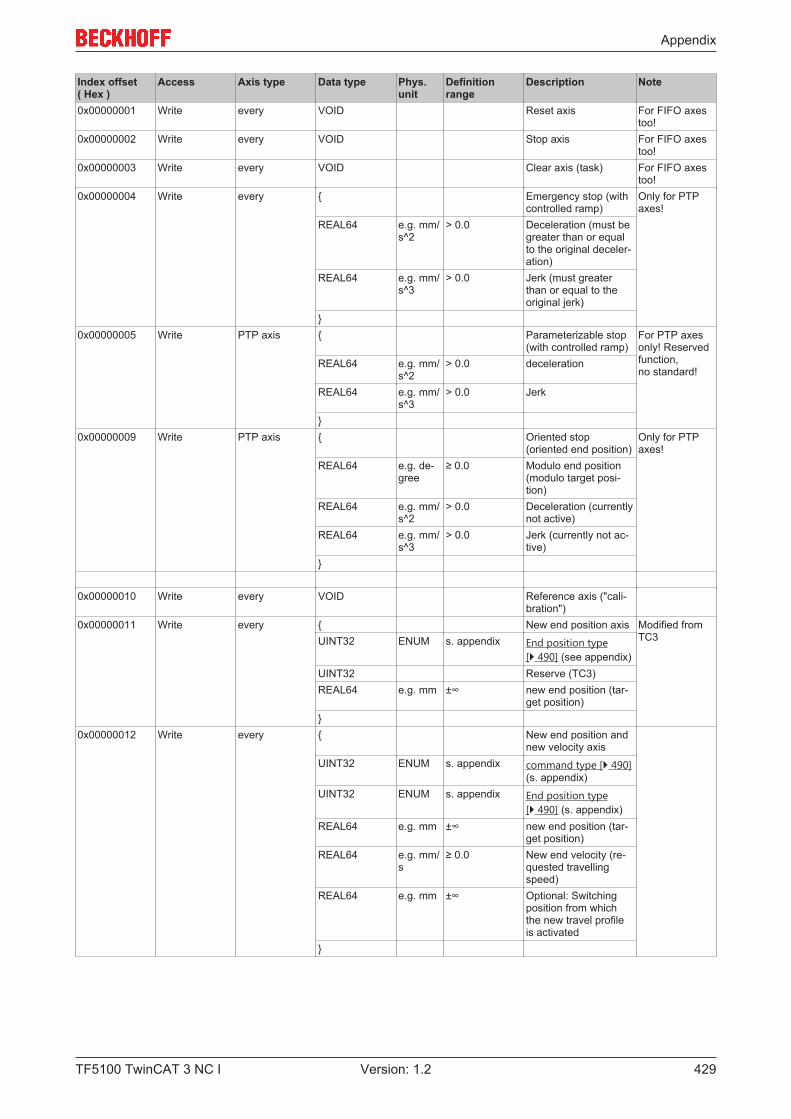
Appendix
TF5100 TwinCAT 3 NC I 429Version: 1.2
Index offset( Hex )
Access Axis type Data type Phys.unit
Definitionrange
Description Note
0x00000001 Write every VOID Reset axis For FIFO axestoo!
0x00000002 Write every VOID Stop axis For FIFO axestoo!
0x00000003 Write every VOID Clear axis (task) For FIFO axestoo!
0x00000004 Write every { Emergency stop (withcontrolled ramp)
Only for PTPaxes!
REAL64 e.g. mm/s^2
> 0.0 Deceleration (must begreater than or equalto the original deceler-ation)
REAL64 e.g. mm/s^3
> 0.0 Jerk (must greaterthan or equal to theoriginal jerk)
}0x00000005 Write PTP axis { Parameterizable stop
(with controlled ramp)For PTP axesonly! Reservedfunction, no standard!
REAL64 e.g. mm/s^2
> 0.0 deceleration
REAL64 e.g. mm/s^3
> 0.0 Jerk
}0x00000009 Write PTP axis { Oriented stop
(oriented end position)Only for PTPaxes!
REAL64 e.g. de-gree
≥ 0.0 Modulo end position(modulo target posi-tion)
REAL64 e.g. mm/s^2
> 0.0 Deceleration (currentlynot active)
REAL64 e.g. mm/s^3
> 0.0 Jerk (currently not ac-tive)
}
0x00000010 Write every VOID Reference axis ("cali-bration")
0x00000011 Write every { New end position axis Modified fromTC3UINT32 ENUM s. appendix End position type
[} 490] (see appendix)UINT32 Reserve (TC3)REAL64 e.g. mm ±∞ new end position (tar-
get position)}
0x00000012 Write every { New end position andnew velocity axis
UINT32 ENUM s. appendix command type [} 490](s. appendix)
UINT32 ENUM s. appendix End position type[} 490] (s. appendix)
REAL64 e.g. mm ±∞ new end position (tar-get position)
REAL64 e.g. mm/s
≥ 0.0 New end velocity (re-quested travellingspeed)
REAL64 e.g. mm ±∞ Optional: Switchingposition from whichthe new travel profileis activated
}
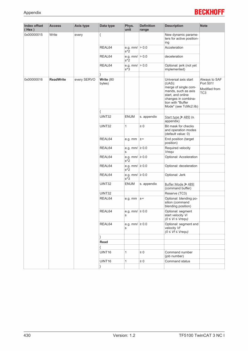
Appendix
TF5100 TwinCAT 3 NC I430 Version: 1.2
Index offset( Hex )
Access Axis type Data type Phys.unit
Definitionrange
Description Note
0x00000015 Write every { New dynamic parame-ters for active position-ing
REAL64 e.g. mm/s^2
> 0.0 Acceleration
REAL64 e.g. mm/s^2
> 0.0 deceleration
REAL64 e.g. mm/s^3
> 0.0 Optional: jerk (not yetimplemented)
}0x00000016 ReadWrite every SERVO Write (80
bytes)Universal axis start(UAS): merge of single com-mands, such as axisstart, and onlinechanges in combina-tion with "BufferMode" (see TcMc2.lib)
Always to SAFPort 501!
Modified fromTC3
{UINT32 ENUM s. appendix Start type [} 489] (s.
appendix)UINT32 1 ≥ 0 Bit mask for checks
and operation modes(default value: 0)
REAL64 e.g. mm ±∞ End position (targetposition)
REAL64 e.g. mm/s
≥ 0.0 Required velocityVrequ
REAL64 e.g. mm/s^2
≥ 0.0 Optional: Acceleration
REAL64 e.g. mm/s^2
≥ 0.0 Optional: deceleration
REAL64 e.g. mm/s^3
≥ 0.0 Optional: Jerk
UINT32 ENUM s. appendix Buffer Mode [} 489](command buffer)
UINT32 Reserve (TC3)REAL64 e.g. mm ±∞ Optional: blending po-
sition (commandblending position)
REAL64 e.g. mm/s
≥ 0.0 Optional: segmentstart velocity Vi(0 ≤ Vi ≤ Vrequ)
REAL64 e.g. mm/s
≥ 0.0 Optional: segment endvelocity Vf (0 ≤ Vf ≤ Vrequ)
}Read{UINT16 1 ≥ 0 Command number
(job number)UINT16 1 ≥ 0 Command status}
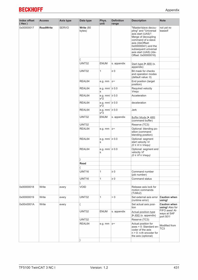
Appendix
TF5100 TwinCAT 3 NC I 431Version: 1.2
Index offset( Hex )
Access Axis type Data type Phys.unit
Definitionrange
Description Note
0x00000017 ReadWrite SERVO Write (80bytes)
"Master/slave decou-pling" and "Universalaxis start (UAS)": Merge of decouplingcommand of a slaveaxis (IdxOffset:0x00000041) and thesubsequent universalaxis start (UAS) (Idx-Offset: 0x00000016)
not yet re-leased!
{UINT32 ENUM s. appendix Start type [} 489] (s.
appendix)UINT32 1 ≥ 0 Bit mask for checks
and operation modes(default value: 0)
REAL64 e.g. mm ±∞ End position (targetposition)
REAL64 e.g. mm/s
≥ 0.0 Required velocityVrequ
REAL64 e.g. mm/s^2
≥ 0.0 Acceleration
REAL64 e.g. mm/s^2
≥ 0.0 deceleration
REAL64 e.g. mm/s^3
≥ 0.0 Jerk
UINT32 ENUM s. appendix Buffer Mode [} 489](command buffer)
UINT32 Reserve (TC3)REAL64 e.g. mm ±∞ Optional: blending po-
sition (commandblending position)
REAL64 e.g. mm/s
≥ 0.0 Optional: segmentstart velocity Vi(0 ≤ Vi ≤ Vrequ)
REAL64 e.g. mm/s
≥ 0.0 Optional: segment endvelocity Vf (0 ≤ Vf ≤ Vrequ)
}Read{UINT16 1 ≥ 0 Command number
(job number)UINT16 1 ≥ 0 Command status}
0x00000018 Write every VOID Release axis lock formotion commands(TcMc2)
0x00000019 Write every UINT32 1 > 0 Set external axis error(runtime error)
Caution whenusing!
0x00n0001A Write every { Set actual axis posi-tion
Caution whenusing! Also forFIFO axes! Al-ways at SAFport 501!
Modified fromTC3
UINT32 ENUM s. appendix Actual position type[} 490] (s. appendix)
UINT32 Reserve (TC3)REAL64 e.g. mm ±∞ Actual position for
axes = 0: Standard en-coder of the axisn > 0: n-th encoder forthe axis (optional)
}
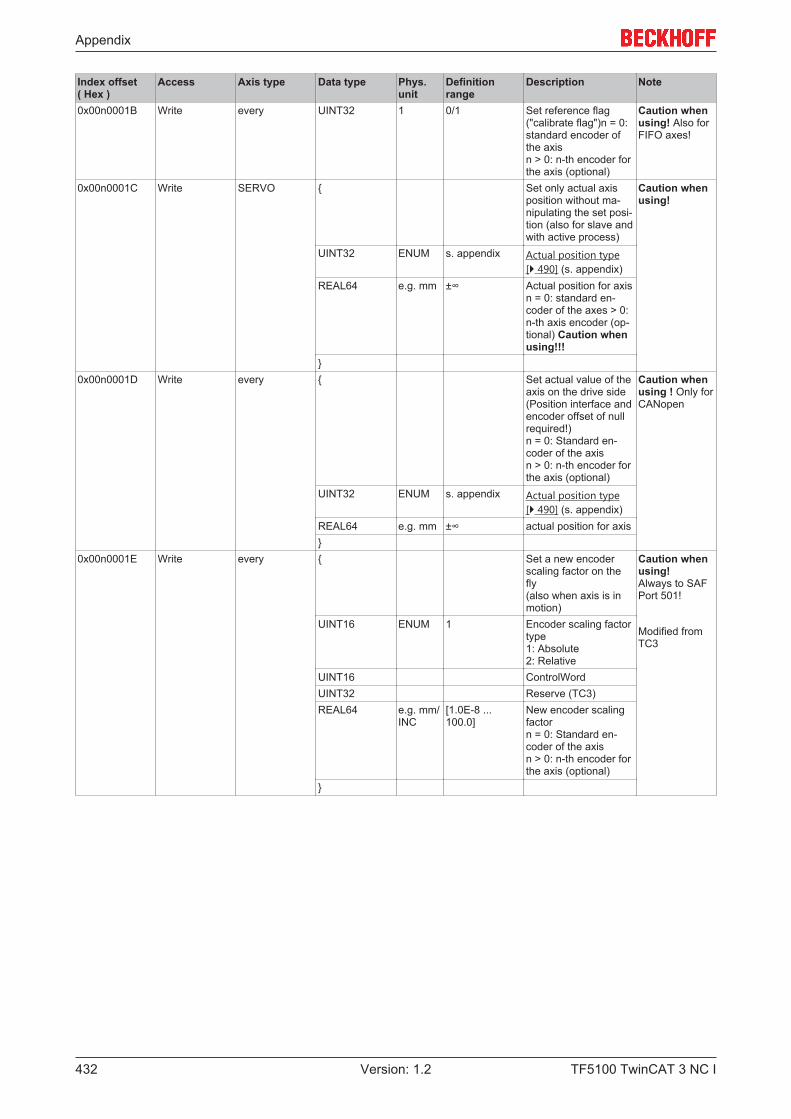
Appendix
TF5100 TwinCAT 3 NC I432 Version: 1.2
Index offset( Hex )
Access Axis type Data type Phys.unit
Definitionrange
Description Note
0x00n0001B Write every UINT32 1 0/1 Set reference flag("calibrate flag")n = 0:standard encoder ofthe axis n > 0: n-th encoder forthe axis (optional)
Caution whenusing! Also forFIFO axes!
0x00n0001C Write SERVO { Set only actual axisposition without ma-nipulating the set posi-tion (also for slave andwith active process)
Caution whenusing!
UINT32 ENUM s. appendix Actual position type[} 490] (s. appendix)
REAL64 e.g. mm ±∞ Actual position for axisn = 0: standard en-coder of the axes > 0:n-th axis encoder (op-tional) Caution whenusing!!!
}0x00n0001D Write every { Set actual value of the
axis on the drive side(Position interface andencoder offset of nullrequired!)n = 0: Standard en-coder of the axisn > 0: n-th encoder forthe axis (optional)
Caution whenusing ! Only forCANopen
UINT32 ENUM s. appendix Actual position type[} 490] (s. appendix)
REAL64 e.g. mm ±∞ actual position for axis}
0x00n0001E Write every { Set a new encoderscaling factor on thefly(also when axis is inmotion)
Caution whenusing! Always to SAFPort 501!
Modified fromTC3
UINT16 ENUM 1 Encoder scaling factortype1: Absolute2: Relative
UINT16 ControlWordUINT32 Reserve (TC3)REAL64 e.g. mm/
INC[1.0E-8 ...100.0]
New encoder scalingfactorn = 0: Standard en-coder of the axisn > 0: n-th encoder forthe axis (optional)
}
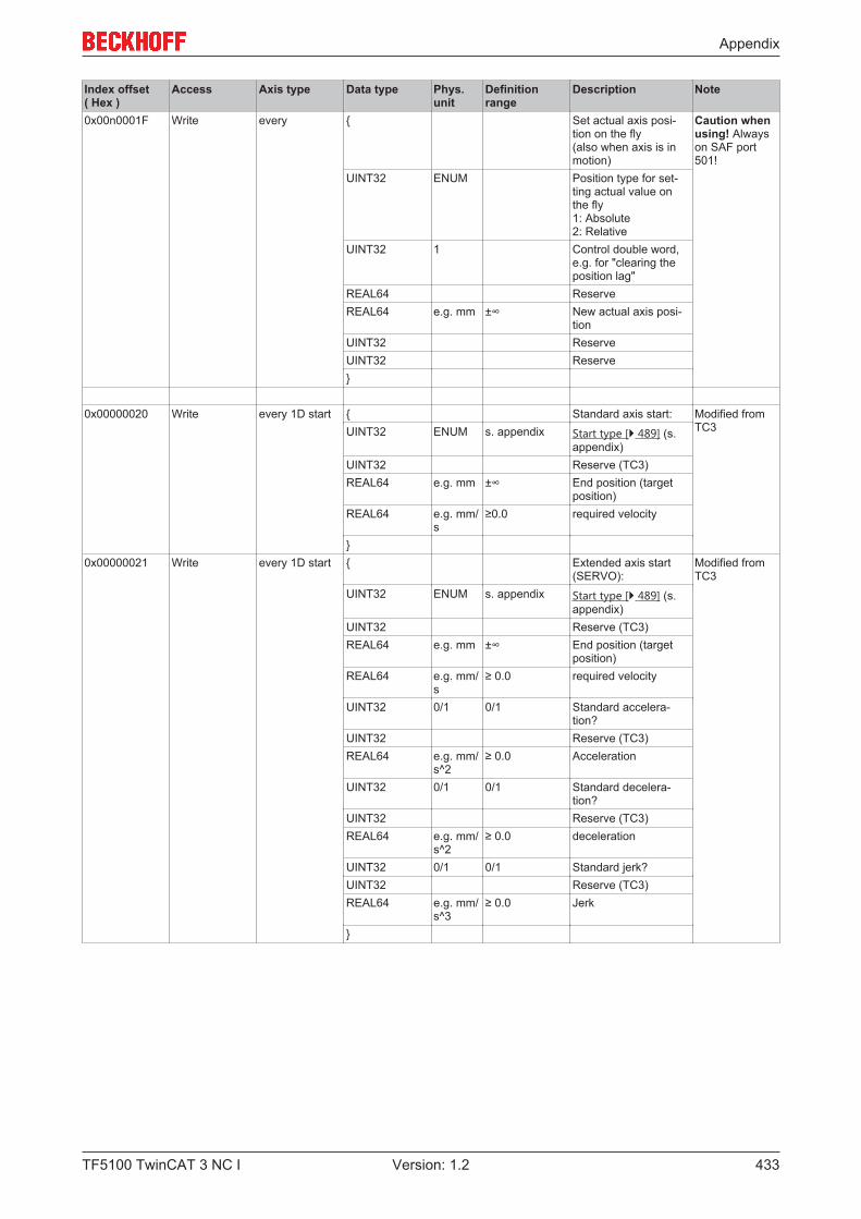
Appendix
TF5100 TwinCAT 3 NC I 433Version: 1.2
Index offset( Hex )
Access Axis type Data type Phys.unit
Definitionrange
Description Note
0x00n0001F Write every { Set actual axis posi-tion on the fly(also when axis is inmotion)
Caution whenusing! Alwayson SAF port501!
UINT32 ENUM Position type for set-ting actual value onthe fly1: Absolute2: Relative
UINT32 1 Control double word,e.g. for "clearing theposition lag"
REAL64 ReserveREAL64 e.g. mm ±∞ New actual axis posi-
tionUINT32 ReserveUINT32 Reserve}
0x00000020 Write every 1D start { Standard axis start: Modified fromTC3UINT32 ENUM s. appendix Start type [} 489] (s.
appendix)UINT32 Reserve (TC3)REAL64 e.g. mm ±∞ End position (target
position)REAL64 e.g. mm/
s≥0.0 required velocity
}0x00000021 Write every 1D start { Extended axis start
(SERVO):Modified fromTC3
UINT32 ENUM s. appendix Start type [} 489] (s.appendix)
UINT32 Reserve (TC3)REAL64 e.g. mm ±∞ End position (target
position)REAL64 e.g. mm/
s≥ 0.0 required velocity
UINT32 0/1 0/1 Standard accelera-tion?
UINT32 Reserve (TC3)REAL64 e.g. mm/
s^2≥ 0.0 Acceleration
UINT32 0/1 0/1 Standard decelera-tion?
UINT32 Reserve (TC3)REAL64 e.g. mm/
s^2≥ 0.0 deceleration
UINT32 0/1 0/1 Standard jerk?UINT32 Reserve (TC3)REAL64 e.g. mm/
s^3≥ 0.0 Jerk
}

Appendix
TF5100 TwinCAT 3 NC I434 Version: 1.2
Index offset( Hex )
Access Axis type Data type Phys.unit
Definitionrange
Description Note
0x00000022 Write SERVO(MW) { Special axis start(SERVO):
Reserved startfunction, nostandard!
Modified fromTC3
UINT32 ENUM s. appendix Start type [} 489] (s.appendix)
UINT32 Reserve (TC3)REAL64 e.g. mm ±∞ End position (target
position)REAL64 mm/s ≥ 0.0 required start velocityREAL64 e.g. mm ±∞ Position for a new ve-
locity levelREAL64 e.g. mm/
s≥ 0.0 new end velocity level
UINT32 0/1 0/1 Standard accelera-tion?
UINT32 Reserve (TC3)REAL64 e.g. mm/
s^2≥ 0.0 Acceleration
UINT32 0/1 0/1 Standard decelera-tion?
UINT32 Reserve (TC3)REAL64 e.g. mm/
s^2≥ 0.0 deceleration
UINT32 0/1 0/1 Standard jerk?UINT32 Reserve (TC3)REAL64 e.g. mm/
s^3≥ 0.0 Jerk
}0x00000023 Write SERVO { Start external set
value specification(setting by cyclic axisinterface PLCtoNC)
Modified fromTC3
UINT32 ENUM 1: Absolute2: Relative
start type [} 489]
UINT32 Reserve (TC3)REAL64 e.g. mm ±∞ New end position (tar-
get position) optional !REAL64 Reserve (TC3)}
0x00000024 Write SERVO VOID Stop/disable externalset value specification(cyclic axis interfacePLCtoNC)
0x00000025 Write SERVO { Start reversing opera-tion for positioning(SERVO):
Modified fromTC3
UINT32 ENUM 1 Start type [} 489] (de-fault: 1)
UINT32 Reserve (TC3)REAL64 e.g. mm ±∞ end position 1 (target
position)REAL64 e.g. mm ±∞ end position 2 (target
position)REAL64 0/1 0/1 required velocityREAL64 s ≥ 0.0 idle time}
0x00000026 Write every { Start drive output: Modified fromTC3UINT32 ENUM s. appendix Output type [} 496] (s.
appendix)UINT32 Reserve (TC3)REAL64 e.g. % ±∞ required output value
(e.g. %)}
0x00000027 Write every VOID Stop drive output
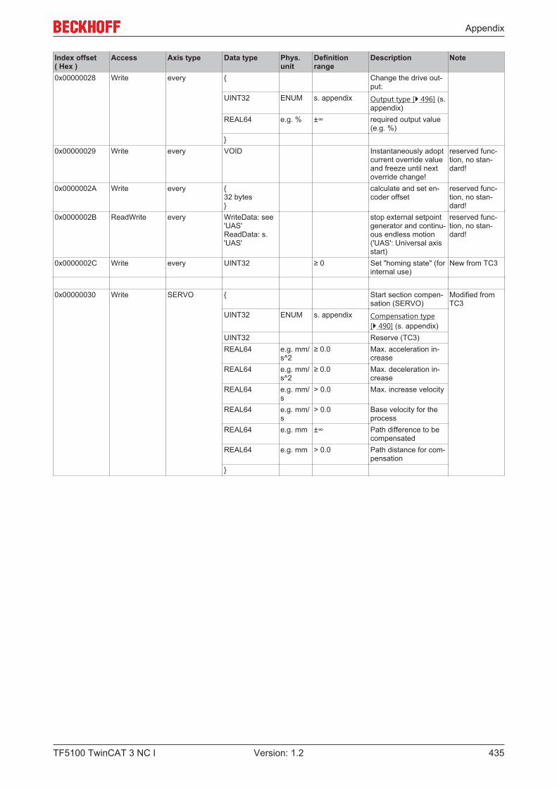
Appendix
TF5100 TwinCAT 3 NC I 435Version: 1.2
Index offset( Hex )
Access Axis type Data type Phys.unit
Definitionrange
Description Note
0x00000028 Write every { Change the drive out-put:
UINT32 ENUM s. appendix Output type [} 496] (s.appendix)
REAL64 e.g. % ±∞ required output value(e.g. %)
}0x00000029 Write every VOID Instantaneously adopt
current override valueand freeze until nextoverride change!
reserved func-tion, no stan-dard!
0x0000002A Write every { 32 bytes }
calculate and set en-coder offset
reserved func-tion, no stan-dard!
0x0000002B ReadWrite every WriteData: see'UAS' ReadData: s.'UAS'
stop external setpointgenerator and continu-ous endless motion('UAS': Universal axisstart)
reserved func-tion, no stan-dard!
0x0000002C Write every UINT32 ≥ 0 Set "homing state" (forinternal use)
New from TC3
0x00000030 Write SERVO { Start section compen-sation (SERVO)
Modified fromTC3
UINT32 ENUM s. appendix Compensation type[} 490] (s. appendix)
UINT32 Reserve (TC3)REAL64 e.g. mm/
s^2≥ 0.0 Max. acceleration in-
creaseREAL64 e.g. mm/
s^2≥ 0.0 Max. deceleration in-
creaseREAL64 e.g. mm/
s> 0.0 Max. increase velocity
REAL64 e.g. mm/s
> 0.0 Base velocity for theprocess
REAL64 e.g. mm ±∞ Path difference to becompensated
REAL64 e.g. mm > 0.0 Path distance for com-pensation
}

Appendix
TF5100 TwinCAT 3 NC I436 Version: 1.2
Index offset( Hex )
Access Axis type Data type Phys.unit
Definitionrange
Description Note
0x00000030 ReadWrite SERVO returnsthe actually im-plemented pa-rameters as re-turn values
{ READ+WRITE:
Start section compen-sation (SERVO)Note: contained onlyin "TcMc2.lib"
Modified fromTC3
UINT32 ENUM s. appendix Compensation type[} 490] (s. appendix)
UINT32 Reserve (TC3)REAL64 e.g. mm/
s^2≥ 0.0 => Max. acceleration
increase<= returns the imple-mented accelerationincrease (new in"TcMc2.lib")
REAL64 e.g. mm/s^2
≥ 0.0 => Max. decelerationincrease<= returns the imple-mented decelerationincrease (new in"TcMc2.lib")
REAL64 e.g. mm/s
> 0.0 => requested max. in-crease velocity<= returns the imple-mented velocity of in-crease
REAL64 e.g. mm/s
> 0.0 Base velocity for theprocess
REAL64 e.g. mm ±∞ => requested path dif-ference to be compen-sated<= returns the imple-mented path differ-ence
REAL64 e.g. mm > 0.0 => requested max.distance for compen-sation<= returns imple-mented distance
UINT32 1 ≥ 0 <= returns Warning ID(e.g. 0x4243)
UINT32 Reserve (TC3)}
0x00000031 Write SERVO VOID Stop section compen-sation (SERVO)
0x00000032 Write SERVO { Start reversing opera-tion with velocity steps(SERVO): (can be used to deter-mine the velocity stepresponse)
Modified fromTC3
UINT32 ENUM 1 Start type [} 489] (de-fault: 1)
UINT32 Reserve (TC3)REAL64 e.g. mm/
s±∞ Required velocity 1
(negative values alsoallowed)
REAL64 e.g. mm/s
±∞ Required velocity 2(negative values alsoallowed)
REAL64 s > 0.0 Travel time for velocity1 and 2
REAL64 s ≥ 0.0 idle timeUINT32 1 0, 1,2,3... Optional: number of
repetitions,Default "0": unlimitedin time
UINT32 Reserve (TC3)}

Appendix
TF5100 TwinCAT 3 NC I 437Version: 1.2
Index offset( Hex )
Access Axis type Data type Phys.unit
Definitionrange
Description Note
0x00000033 Write SERVO { Sinus Oscillation Se-quence - used as single sinusoscillation (sinus gen-erator) - used as sinus oscilla-tion sequence (e.g. forbode plot)
Modified fromTC3
UINT32 ENUM 1 Start type [} 489](fixed to start type 1yet)
UINT32 Reserve (TC3)REAL64 e.g. mm/
s> 0.0 base amplitude (e.g.
2.5 mm/s)REAL64 Hz [0.0 .... 10.0] base frequency (e.g.
1.953125 Hz)REAL64 e.g. mm/
s≥ 0.0 start amplitude at be-
gin (e.g. 0.0 mm/s)REAL64 e.g. mm/
REV> 0.0 feed constant motor
(per motor turn) (e.g.10.0 mm/REV)
REAL64 Hz ≥ 1.0 frequency range: startfrequency (e.g. 20.0Hz)
REAL64 Hz ≤ 1/(2*dT) frequency range: stopfrequency (e.g. 500.0Hz)
REAL64 s > 0.0 step duration (e.g.2.048s)
UINT32 1 [1 ... 200] number of measure-ments (step cycles)(e.g. 20)
UINT32 1 number of parallelmeasurements (e.g. 1)not used yet!
}
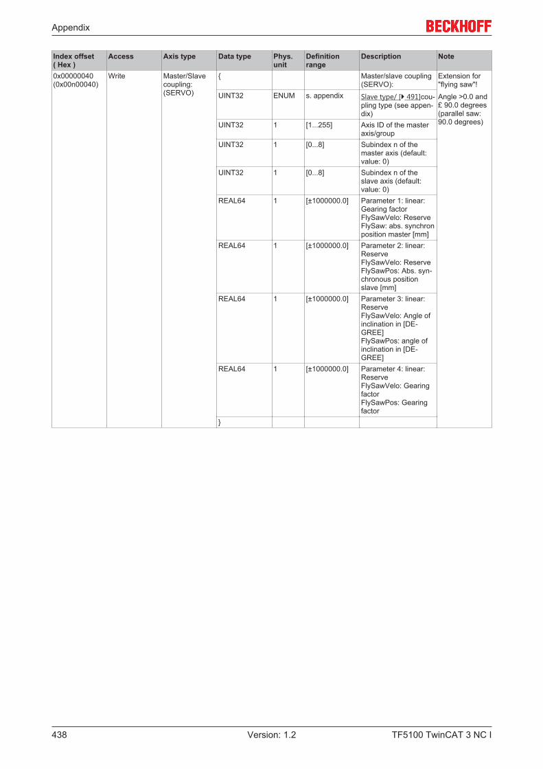
Appendix
TF5100 TwinCAT 3 NC I438 Version: 1.2
Index offset( Hex )
Access Axis type Data type Phys.unit
Definitionrange
Description Note
0x00000040(0x00n00040)
Write Master/Slavecoupling:(SERVO)
{ Master/slave coupling(SERVO):
Extension for"flying saw"!
Angle >0.0 and£ 90.0 degrees(parallel saw:90.0 degrees)
UINT32 ENUM s. appendix Slave type/ [} 491]cou-pling type (see appen-dix)
UINT32 1 [1...255] Axis ID of the masteraxis/group
UINT32 1 [0...8] Subindex n of themaster axis (default:value: 0)
UINT32 1 [0...8] Subindex n of theslave axis (default:value: 0)
REAL64 1 [±1000000.0] Parameter 1: linear:Gearing factorFlySawVelo: ReserveFlySaw: abs. synchronposition master [mm]
REAL64 1 [±1000000.0] Parameter 2: linear:ReserveFlySawVelo: ReserveFlySawPos: Abs. syn-chronous positionslave [mm]
REAL64 1 [±1000000.0] Parameter 3: linear:ReserveFlySawVelo: Angle ofinclination in [DE-GREE]FlySawPos: angle ofinclination in [DE-GREE]
REAL64 1 [±1000000.0] Parameter 4: linear:ReserveFlySawVelo: GearingfactorFlySawPos: Gearingfactor
}
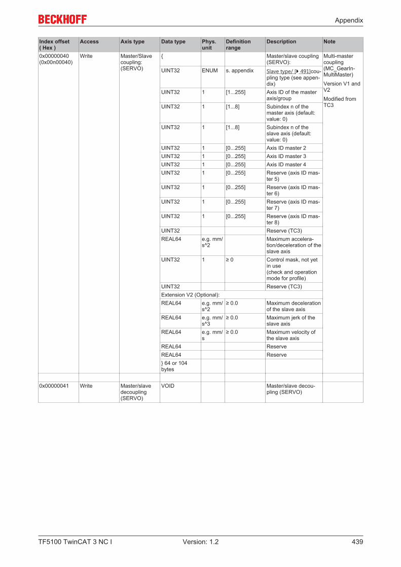
Appendix
TF5100 TwinCAT 3 NC I 439Version: 1.2
Index offset( Hex )
Access Axis type Data type Phys.unit
Definitionrange
Description Note
0x00000040(0x00n00040)
Write Master/Slavecoupling:(SERVO)
{ Master/slave coupling(SERVO):
Multi-mastercoupling(MC_GearIn-MultiMaster)
Version V1 andV2
Modified fromTC3
UINT32 ENUM s. appendix Slave type/ [} 491]cou-pling type (see appen-dix)
UINT32 1 [1...255] Axis ID of the masteraxis/group
UINT32 1 [1...8] Subindex n of themaster axis (default:value: 0)
UINT32 1 [1...8] Subindex n of theslave axis (default:value: 0)
UINT32 1 [0...255] Axis ID master 2UINT32 1 [0...255] Axis ID master 3UINT32 1 [0...255] Axis ID master 4UINT32 1 [0...255] Reserve (axis ID mas-
ter 5)UINT32 1 [0...255] Reserve (axis ID mas-
ter 6)UINT32 1 [0...255] Reserve (axis ID mas-
ter 7)UINT32 1 [0...255] Reserve (axis ID mas-
ter 8)UINT32 Reserve (TC3)REAL64 e.g. mm/
s^2Maximum accelera-tion/deceleration of theslave axis
UINT32 1 ≥ 0 Control mask, not yetin use(check and operationmode for profile)
UINT32 Reserve (TC3)Extension V2 (Optional):REAL64 e.g. mm/
s^2≥ 0.0 Maximum deceleration
of the slave axisREAL64 e.g. mm/
s^3≥ 0.0 Maximum jerk of the
slave axisREAL64 e.g. mm/
s≥ 0.0 Maximum velocity of
the slave axisREAL64 ReserveREAL64 Reserve} 64 or 104bytes
0x00000041 Write Master/slavedecoupling(SERVO)
VOID Master/slave decou-pling (SERVO)
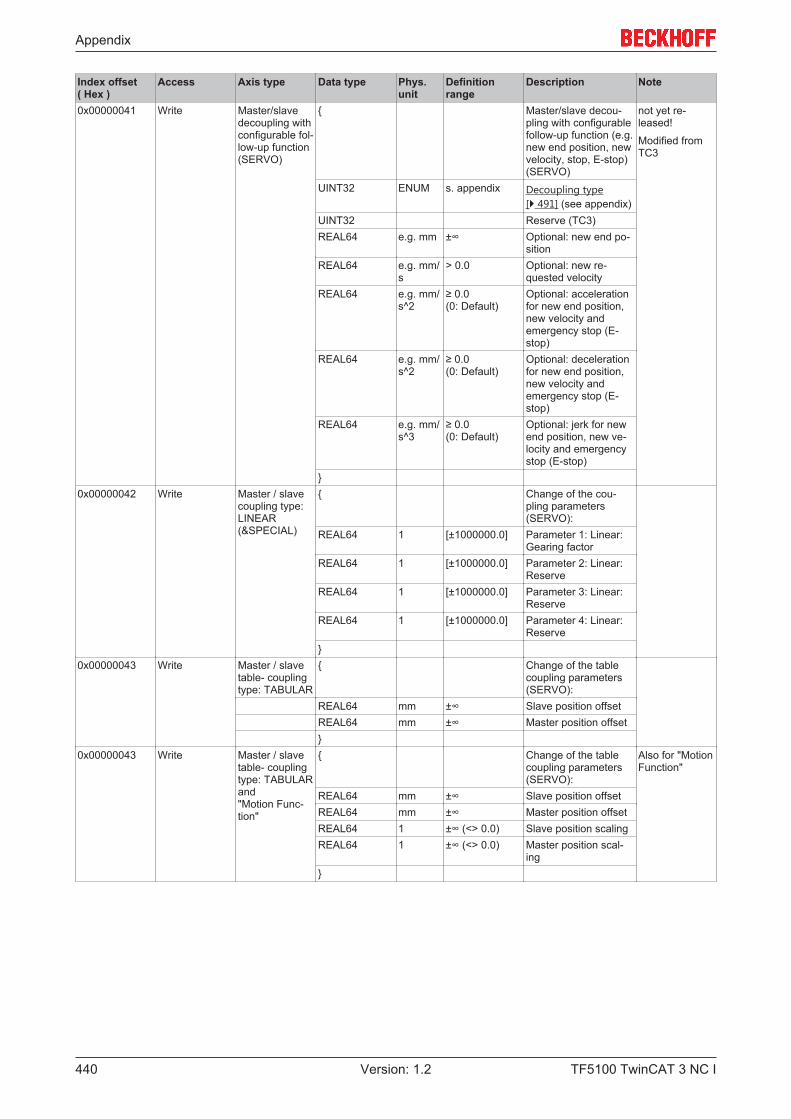
Appendix
TF5100 TwinCAT 3 NC I440 Version: 1.2
Index offset( Hex )
Access Axis type Data type Phys.unit
Definitionrange
Description Note
0x00000041 Write Master/slavedecoupling withconfigurable fol-low-up function(SERVO)
{ Master/slave decou-pling with configurablefollow-up function (e.g.new end position, newvelocity, stop, E-stop)(SERVO)
not yet re-leased!
Modified fromTC3
UINT32 ENUM s. appendix Decoupling type[} 491] (see appendix)
UINT32 Reserve (TC3)REAL64 e.g. mm ±∞ Optional: new end po-
sitionREAL64 e.g. mm/
s> 0.0 Optional: new re-
quested velocityREAL64 e.g. mm/
s^2≥ 0.0 (0: Default)
Optional: accelerationfor new end position,new velocity andemergency stop (E-stop)
REAL64 e.g. mm/s^2
≥ 0.0 (0: Default)
Optional: decelerationfor new end position,new velocity andemergency stop (E-stop)
REAL64 e.g. mm/s^3
≥ 0.0 (0: Default)
Optional: jerk for newend position, new ve-locity and emergencystop (E-stop)
}0x00000042 Write Master / slave
coupling type:LINEAR(&SPECIAL)
{ Change of the cou-pling parameters(SERVO):
REAL64 1 [±1000000.0] Parameter 1: Linear:Gearing factor
REAL64 1 [±1000000.0] Parameter 2: Linear:Reserve
REAL64 1 [±1000000.0] Parameter 3: Linear:Reserve
REAL64 1 [±1000000.0] Parameter 4: Linear:Reserve
}0x00000043 Write Master / slave
table- couplingtype: TABULAR
{ Change of the tablecoupling parameters(SERVO):
REAL64 mm ±∞ Slave position offsetREAL64 mm ±∞ Master position offset}
0x00000043 Write Master / slavetable- couplingtype: TABULAR and "Motion Func-tion"
{ Change of the tablecoupling parameters(SERVO):
Also for "MotionFunction"
REAL64 mm ±∞ Slave position offsetREAL64 mm ±∞ Master position offsetREAL64 1 ±∞ (<> 0.0) Slave position scalingREAL64 1 ±∞ (<> 0.0) Master position scal-
ing}
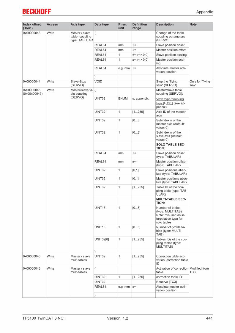
Appendix
TF5100 TwinCAT 3 NC I 441Version: 1.2
Index offset( Hex )
Access Axis type Data type Phys.unit
Definitionrange
Description Note
0x00000043 Write Master / slavetable- couplingtype: TABULAR
{ Change of the tablecoupling parameters(SERVO):
REAL64 mm ±∞ Slave position offsetREAL64 mm ±∞ Master position offsetREAL64 1 ±∞ (<> 0.0) Slave position scalingREAL64 1 ±∞ (<> 0.0) Master position scal-
ingREAL64 e.g. mm ±∞ Absolute master acti-
vation position}
0x00000044 Write Slave-Stop(SERVO)
VOID Stop the "flyingsaw" (SERVO)
Only for "flyingsaw"
0x00000045(0x00n00045)
Write Master/slave ta-ble coupling(SERVO)
{ Master/slave tablecoupling (SERVO):
UINT32 ENUM s. appendix Slave type/couplingtype [} 491] (see ap-pendix)
UINT32 1 [1...255] Axis ID of the masteraxis
UINT32 1 [0...8] Subindex n of themaster axis (default:value: 0)
UINT32 1 [0...8] Subindex n of theslave axis (default:value: 0)SOLO TABLE SEC-TION:
REAL64 mm ±∞ Slave position offset(type: TABULAR)
REAL64 mm ±∞ Master position offset(type: TABULAR)
UINT32 1 [0,1] Slave positions abso-lute (type: TABULAR)
UINT32 1 [0,1] Master positions abso-lute (type: TABULAR)
UINT32 1 [1...255] Table ID of the cou-pling table (type: TAB-ULAR)MULTI-TABLE SEC-TION:
UINT16 1 [0...8] Number of tables(type: MULTITAB)Note: misused as in-terpolation type forsolo tables
UNIT16 1 [0...8] Number of profile ta-bles (type: MULTI-TAB)
UNIT32[8] 1 [1...255] Tables IDs of the cou-pling tables (type:MULTITAB)
}0x00000046 Write Master / slave
multi-tablesUINT32 1 [1...255] Correction table acti-
vation, correction tableID
0x00000046 Write Master / slavemulti-tables
{ Activation of correctiontable
Modified fromTC3
UINT32 1 [1...255] correction table IDUINT32 Reserve (TC3)REAL64 e.g. mm ±∞ Absolute master acti-
vation position}

Appendix
TF5100 TwinCAT 3 NC I442 Version: 1.2
Index offset( Hex )
Access Axis type Data type Phys.unit
Definitionrange
Description Note
0x00000047 Write Master / slavemulti-tables
UINT32 1 [1..255] Deactivation of profiletable at the end of thecycle, table ID of thecurrent monocyclicprofile table
0x00000048 ReadWrite Master / slavemulti-tables
Write: UINT32 1 [1..255] Read the last correc-tion offset: Table ID ofthe correction table
Read: REAL32 e.g. mm ±∞ Offset by departing thecorrection table withthe according table ID
0x00000049 Write Master / slavetable- couplingtype: TABULAR
REAL64 1 ±∞ Change the slave ta-ble scaling factor forthe slave table column (default value: 1.0)
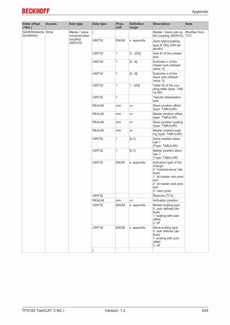
Appendix
TF5100 TwinCAT 3 NC I 443Version: 1.2
Index offset( Hex )
Access Axis type Data type Phys.unit
Definitionrange
Description Note
0x0000004A(0x00n0004A)
Write Master / slaveuniversal tablecoupling(SERVO)
{ Master / slave solo ta-ble coupling (SERVO):
Modified fromTC3
UINT32 ENUM s. appendix Slave type/couplingtype [} 491] (see ap-pendix)
UINT32 1 [1...255] Axis ID of the masteraxis
UINT32 1 [0...8] Subindex n of themaster axis (default:value: 0)
UINT32 1 [0...8] Subindex n of theslave axis (default:value: 0)
UINT32 1 1...255] Table ID of the cou-pling table (type: TAB-ULAR)
UINT32 1 Tabular interpolationtype
REAL64 mm ±∞ Slave position offset(type: TABULAR)
REAL64 mm ±∞ Master position offset(type: TABULAR)
REAL64 mm ±∞ Slave position scaling(type: TABULAR)
REAL64 mm ±∞ Master position scal-ing (type: TABULAR)
UINT32 1 [0,1] Slave position abso-lute ? (Type: TABULAR)
UINT32 1 [0,1] Master position abso-lute ? (Type: TABULAR)
UINT32 ENUM s. appendix Activation type of thechange: 0: 'instantaneous' (de-fault) 1: 'at master cam posi-tion' 2: 'at master axis posi-tion' 3: 'next cycle'
UINT32 Reserve (TC3)REAL64 mm ±∞ Activation positionUINT32 ENUM s. appendix Master scaling type:
0: user defined (de-fault) 1: scaling with autooffset 2: off
UINT32 ENUM s. appendix Slave scaling type: 0: user defined (de-fault) 1: scaling with autooffset 2: off
}
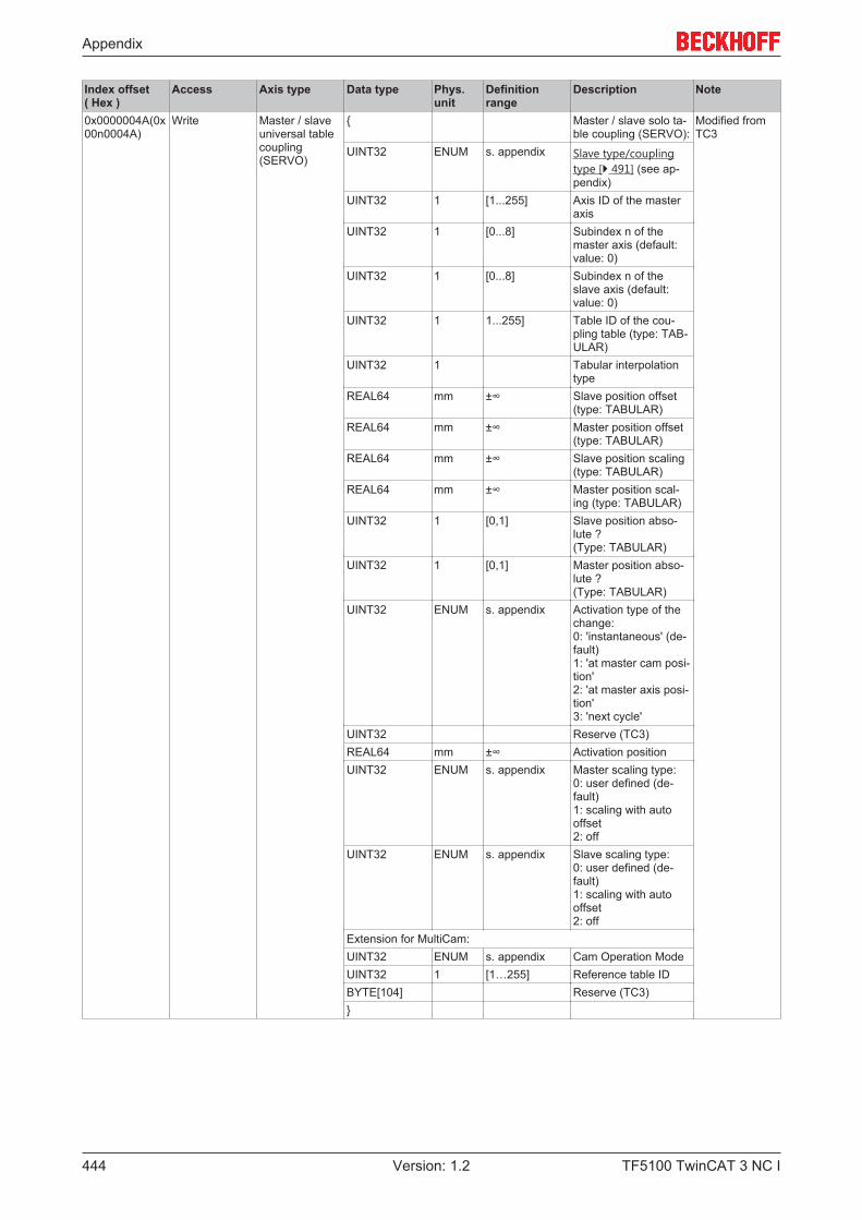
Appendix
TF5100 TwinCAT 3 NC I444 Version: 1.2
Index offset( Hex )
Access Axis type Data type Phys.unit
Definitionrange
Description Note
0x0000004A(0x00n0004A)
Write Master / slaveuniversal tablecoupling(SERVO)
{ Master / slave solo ta-ble coupling (SERVO):
Modified fromTC3
UINT32 ENUM s. appendix Slave type/couplingtype [} 491] (see ap-pendix)
UINT32 1 [1...255] Axis ID of the masteraxis
UINT32 1 [0...8] Subindex n of themaster axis (default:value: 0)
UINT32 1 [0...8] Subindex n of theslave axis (default:value: 0)
UINT32 1 1...255] Table ID of the cou-pling table (type: TAB-ULAR)
UINT32 1 Tabular interpolationtype
REAL64 mm ±∞ Slave position offset(type: TABULAR)
REAL64 mm ±∞ Master position offset(type: TABULAR)
REAL64 mm ±∞ Slave position scaling(type: TABULAR)
REAL64 mm ±∞ Master position scal-ing (type: TABULAR)
UINT32 1 [0,1] Slave position abso-lute ? (Type: TABULAR)
UINT32 1 [0,1] Master position abso-lute ? (Type: TABULAR)
UINT32 ENUM s. appendix Activation type of thechange: 0: 'instantaneous' (de-fault) 1: 'at master cam posi-tion' 2: 'at master axis posi-tion' 3: 'next cycle'
UINT32 Reserve (TC3)REAL64 mm ±∞ Activation positionUINT32 ENUM s. appendix Master scaling type:
0: user defined (de-fault) 1: scaling with autooffset 2: off
UINT32 ENUM s. appendix Slave scaling type: 0: user defined (de-fault) 1: scaling with autooffset 2: off
Extension for MultiCam:UINT32 ENUM s. appendix Cam Operation ModeUINT32 1 [1…255] Reference table IDBYTE[104] Reserve (TC3)}
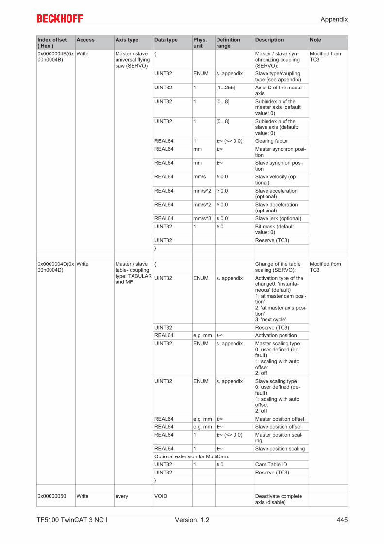
Appendix
TF5100 TwinCAT 3 NC I 445Version: 1.2
Index offset( Hex )
Access Axis type Data type Phys.unit
Definitionrange
Description Note
0x0000004B(0x00n0004B)
Write Master / slaveuniversal flyingsaw (SERVO)
{ Master / slave syn-chronizing coupling(SERVO):
Modified fromTC3
UINT32 ENUM s. appendix Slave type/couplingtype (see appendix)
UINT32 1 [1...255] Axis ID of the masteraxis
UINT32 1 [0...8] Subindex n of themaster axis (default:value: 0)
UINT32 1 [0...8] Subindex n of theslave axis (default:value: 0)
REAL64 1 ±∞ (<> 0.0) Gearing factorREAL64 mm ±∞ Master synchron posi-
tionREAL64 mm ±∞ Slave synchron posi-
tionREAL64 mm/s ≥ 0.0 Slave velocity (op-
tional)REAL64 mm/s^2 ≥ 0.0 Slave acceleration
(optional)REAL64 mm/s^2 ≥ 0.0 Slave deceleration
(optional)REAL64 mm/s^3 ≥ 0.0 Slave jerk (optional)UINT32 1 ≥ 0 Bit mask (default
value: 0)UINT32 Reserve (TC3)}
0x0000004D(0x00n0004D)
Write Master / slavetable- couplingtype: TABULAR and MF
{ Change of the tablescaling (SERVO):
Modified fromTC3
UINT32 ENUM s. appendix Activation type of thechange0: 'instanta-neous' (default)1: at master cam posi-tion' 2: 'at master axis posi-tion' 3: 'next cycle'
UINT32 Reserve (TC3)REAL64 e.g. mm ±∞ Activation positionUINT32 ENUM s. appendix Master scaling type
0: user defined (de-fault) 1: scaling with autooffset 2: off
UINT32 ENUM s. appendix Slave scaling type0: user defined (de-fault) 1: scaling with autooffset 2: off
REAL64 e.g. mm ±∞ Master position offsetREAL64 e.g. mm ±∞ Slave position offsetREAL64 1 ±∞ (<> 0.0) Master position scal-
ingREAL64 1 ±∞ Slave position scalingOptional extension for MultiCam:UINT32 1 ≥ 0 Cam Table IDUINT32 Reserve (TC3)}
0x00000050 Write every VOID Deactivate completeaxis (disable)
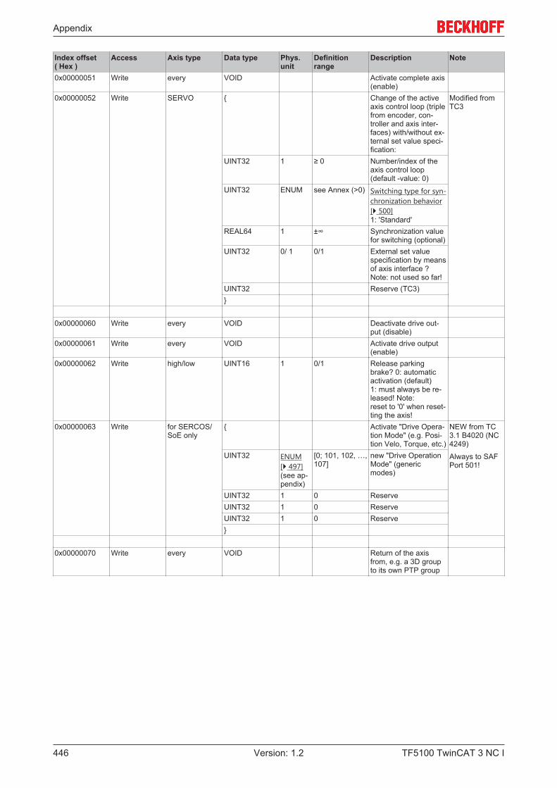
Appendix
TF5100 TwinCAT 3 NC I446 Version: 1.2
Index offset( Hex )
Access Axis type Data type Phys.unit
Definitionrange
Description Note
0x00000051 Write every VOID Activate complete axis(enable)
0x00000052 Write SERVO { Change of the activeaxis control loop (triplefrom encoder, con-troller and axis inter-faces) with/without ex-ternal set value speci-fication:
Modified fromTC3
UINT32 1 ≥ 0 Number/index of theaxis control loop (default -value: 0)
UINT32 ENUM see Annex (>0) Switching type for syn-chronization behavior[} 500] 1: 'Standard'
REAL64 1 ±∞ Synchronization valuefor switching (optional)
UINT32 0/ 1 0/1 External set valuespecification by meansof axis interface ? Note: not used so far!
UINT32 Reserve (TC3)}
0x00000060 Write every VOID Deactivate drive out-put (disable)
0x00000061 Write every VOID Activate drive output(enable)
0x00000062 Write high/low UINT16 1 0/1 Release parkingbrake? 0: automaticactivation (default)1: must always be re-leased! Note: reset to '0' when reset-ting the axis!
0x00000063 Write for SERCOS/SoE only
{ Activate "Drive Opera-tion Mode" (e.g. Posi-tion Velo, Torque, etc.)
NEW from TC3.1 B4020 (NC4249)
Always to SAFPort 501!
UINT32 ENUM[} 497] (see ap-pendix)
[0; 101, 102, …,107]
new "Drive OperationMode" (genericmodes)
UINT32 1 0 ReserveUINT32 1 0 ReserveUINT32 1 0 Reserve}
0x00000070 Write every VOID Return of the axisfrom, e.g. a 3D groupto its own PTP group

Appendix
TF5100 TwinCAT 3 NC I 447Version: 1.2
7.8.4.4 "Index offset" specification for cyclic Axis process data (Index group0x4300 + ID)
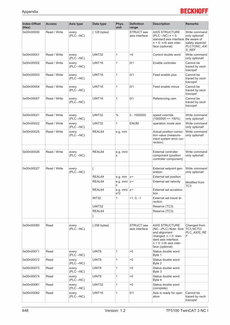
Appendix
TF5100 TwinCAT 3 NC I448 Version: 1.2
Index-Offset(Hex)
Access Axis type Data type Phys.unit
Definitionrange
Description Remarks
0x00n00000 Read / Write every(PLC→NC)
{ 128 bytes} STRUCT seeaxis interface
AXIS STRUCTURE(PLC→NC) n = 0:standard axis interfacen > 0: n-th axis inter-face (optional)
Write commandonly optional!Be aware ofsafety aspects!PLCTONC_AXIS_REF
0x00n00001 Read / Write every(PLC→NC)
UINT32 1 >0 Control double word Write commandonly optional!
0x00n00002 Read / Write every(PLC→NC)
UINT16 1 0/1 Enable controller Cannot betraced by oscil-loscope!
0x00n00003 Read / Write every(PLC→NC)
UINT16 1 0/1 Feed enable plus Cannot betraced by oscil-loscope!
0x00n00004 Read / Write every(PLC→NC)
UINT16 1 0/1 Feed enable minus Cannot betraced by oscil-loscope!
0x00n00007 Read / Write every(PLC→NC)
UINT16 1 0/1 Referencing cam Cannot betraced by oscil-loscope!
0x00n00021 Read / Write every(PLC→NC)
UINT32 % 0...1000000 speed override(1000000 == 100%)
Write commandonly optional!
0x00n00022 Read / Write every(PLC→NC)
UINT32 1 ENUM operation mode axis Write commandonly optional!
0x00n00025 Read / Write every(PLC→NC)
REAL64 e.g. mm Actual position correc-tion value (measure-ment system error cor-rection)
Write commandonly optional!
0x00n00026 Read / Write every(PLC→NC)
REAL64 e.g. mm/s
External controllercomponent (positioncontroller component)
Write commandonly optional!
0x00n00027 Read / Write every(PLC→NC)
{ External setpoint gen-eration
Write commandonly optional!
Modified fromTC3
REAL64 e.g. mm ±∞ External set positionREAL64 e.g. mm/
s±∞ External set velocity
REAL64 e.g. mm/s^2
±∞ External set accelera-tion
INT32 1 +1, 0, -1 External set travel di-rection
UINT32 Reserve (TC3)REAL64 Reserve (TC3)}
0x00n00080 Read every(PLC→NC)
{ 256 bytes} STRUCT seeaxis interface
AXIS STRUCTURE(NC→PLC) Note: Sizeand alignmentchanged, n = 0: stan-dard axis interfacen > 0: n-th axis inter-face (optional)
Changed fromTC3.NCTO-PLC_AXIS_REF
0x00n00071 Read every(PLC→NC)
UINT8 1 >0 Status double word:Byte 1
0x00n00072 Read every(PLC→NC)
UINT8 1 >0 Status double word:Byte 2
0x00n00073 Read every(PLC→NC)
UINT8 1 >0 Status double word:Byte 3
0x00n00074 Read every(PLC→NC)
UINT8 1 >0 Status double word:Byte 4
0x00n00081 Read every(PLC→NC)
UINT32 1 >0 Status double word(complete)
0x00n00082 Read every(PLC→NC)
UINT16 1 0/1 Axis is ready for oper-ation
Cannot betraced by oscil-loscope!
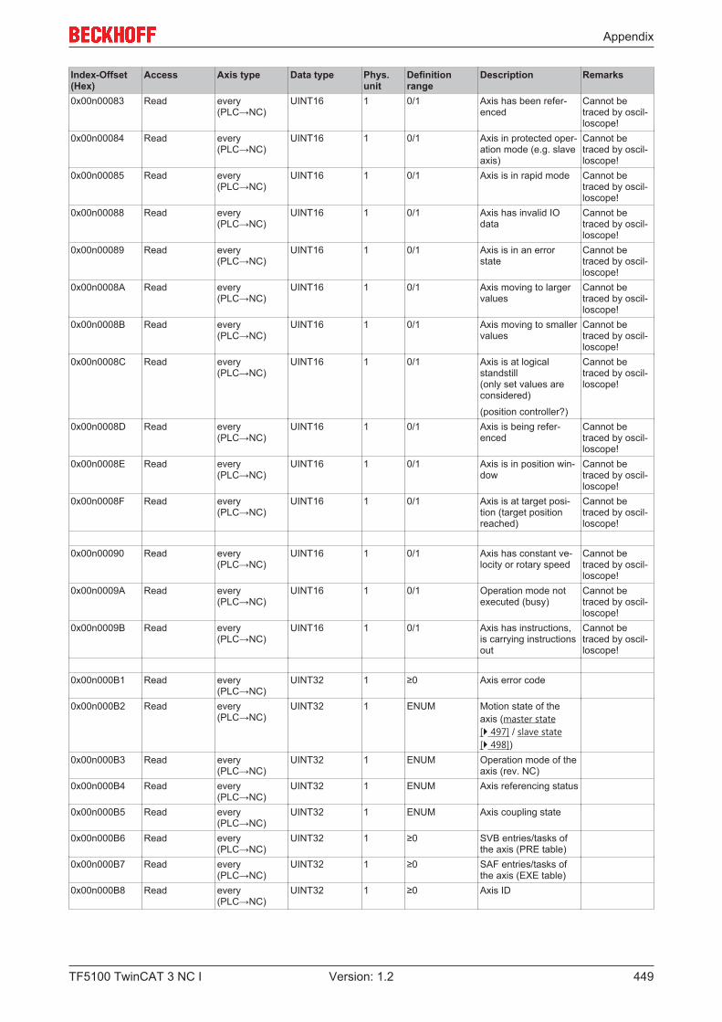
Appendix
TF5100 TwinCAT 3 NC I 449Version: 1.2
Index-Offset(Hex)
Access Axis type Data type Phys.unit
Definitionrange
Description Remarks
0x00n00083 Read every(PLC→NC)
UINT16 1 0/1 Axis has been refer-enced
Cannot betraced by oscil-loscope!
0x00n00084 Read every(PLC→NC)
UINT16 1 0/1 Axis in protected oper-ation mode (e.g. slaveaxis)
Cannot betraced by oscil-loscope!
0x00n00085 Read every(PLC→NC)
UINT16 1 0/1 Axis is in rapid mode Cannot betraced by oscil-loscope!
0x00n00088 Read every(PLC→NC)
UINT16 1 0/1 Axis has invalid IOdata
Cannot betraced by oscil-loscope!
0x00n00089 Read every(PLC→NC)
UINT16 1 0/1 Axis is in an errorstate
Cannot betraced by oscil-loscope!
0x00n0008A Read every(PLC→NC)
UINT16 1 0/1 Axis moving to largervalues
Cannot betraced by oscil-loscope!
0x00n0008B Read every(PLC→NC)
UINT16 1 0/1 Axis moving to smallervalues
Cannot betraced by oscil-loscope!
0x00n0008C Read every(PLC→NC)
UINT16 1 0/1 Axis is at logicalstandstill(only set values areconsidered)
(position controller?)
Cannot betraced by oscil-loscope!
0x00n0008D Read every(PLC→NC)
UINT16 1 0/1 Axis is being refer-enced
Cannot betraced by oscil-loscope!
0x00n0008E Read every(PLC→NC)
UINT16 1 0/1 Axis is in position win-dow
Cannot betraced by oscil-loscope!
0x00n0008F Read every(PLC→NC)
UINT16 1 0/1 Axis is at target posi-tion (target positionreached)
Cannot betraced by oscil-loscope!
0x00n00090 Read every(PLC→NC)
UINT16 1 0/1 Axis has constant ve-locity or rotary speed
Cannot betraced by oscil-loscope!
0x00n0009A Read every(PLC→NC)
UINT16 1 0/1 Operation mode notexecuted (busy)
Cannot betraced by oscil-loscope!
0x00n0009B Read every(PLC→NC)
UINT16 1 0/1 Axis has instructions,is carrying instructionsout
Cannot betraced by oscil-loscope!
0x00n000B1 Read every(PLC→NC)
UINT32 1 ≥0 Axis error code
0x00n000B2 Read every(PLC→NC)
UINT32 1 ENUM Motion state of theaxis (master state[} 497] / slave state[} 498])
0x00n000B3 Read every(PLC→NC)
UINT32 1 ENUM Operation mode of theaxis (rev. NC)
0x00n000B4 Read every(PLC→NC)
UINT32 1 ENUM Axis referencing status
0x00n000B5 Read every(PLC→NC)
UINT32 1 ENUM Axis coupling state
0x00n000B6 Read every(PLC→NC)
UINT32 1 ≥0 SVB entries/tasks ofthe axis (PRE table)
0x00n000B7 Read every(PLC→NC)
UINT32 1 ≥0 SAF entries/tasks ofthe axis (EXE table)
0x00n000B8 Read every(PLC→NC)
UINT32 1 ≥0 Axis ID
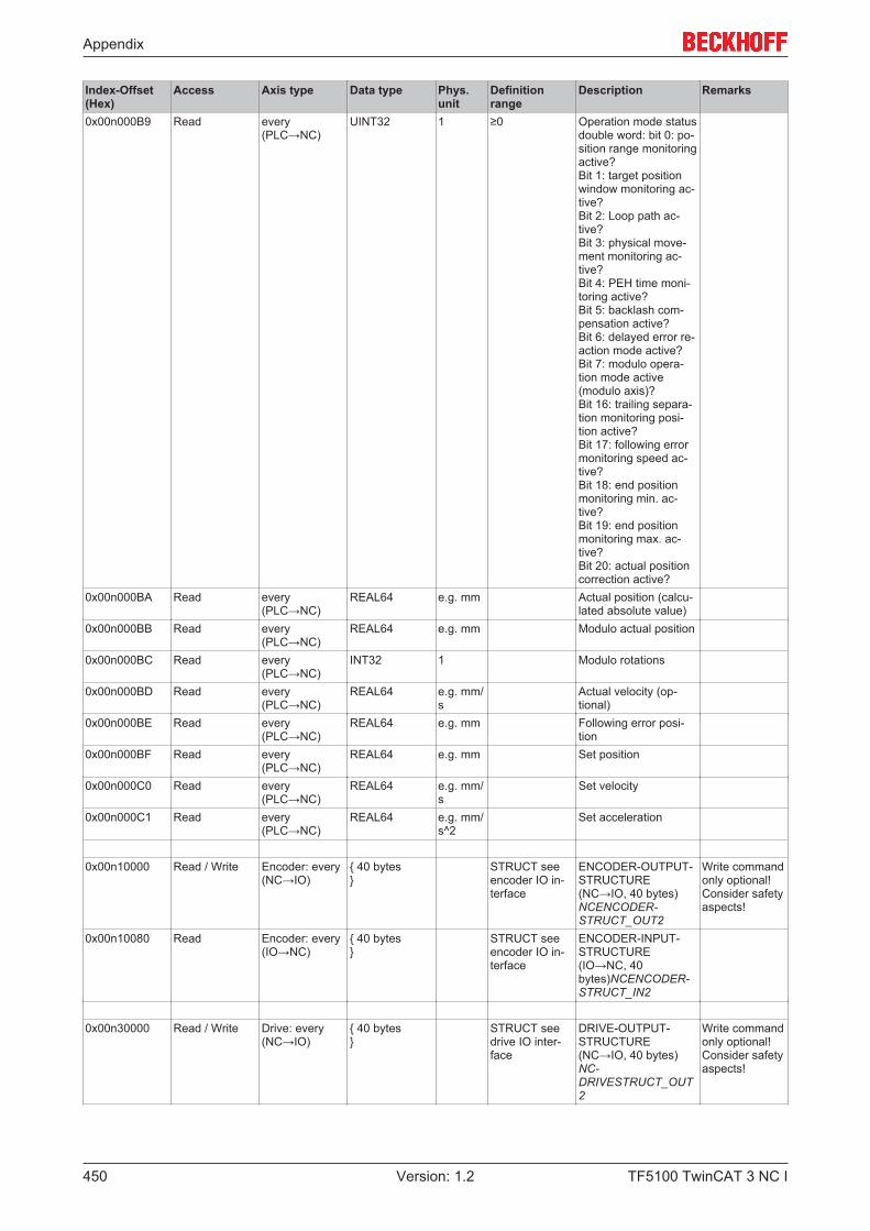
Appendix
TF5100 TwinCAT 3 NC I450 Version: 1.2
Index-Offset(Hex)
Access Axis type Data type Phys.unit
Definitionrange
Description Remarks
0x00n000B9 Read every(PLC→NC)
UINT32 1 ≥0 Operation mode statusdouble word: bit 0: po-sition range monitoringactive?Bit 1: target positionwindow monitoring ac-tive?Bit 2: Loop path ac-tive?Bit 3: physical move-ment monitoring ac-tive?Bit 4: PEH time moni-toring active?Bit 5: backlash com-pensation active?Bit 6: delayed error re-action mode active?Bit 7: modulo opera-tion mode active(modulo axis)?Bit 16: trailing separa-tion monitoring posi-tion active?Bit 17: following errormonitoring speed ac-tive?Bit 18: end positionmonitoring min. ac-tive?Bit 19: end positionmonitoring max. ac-tive?Bit 20: actual positioncorrection active?
0x00n000BA Read every(PLC→NC)
REAL64 e.g. mm Actual position (calcu-lated absolute value)
0x00n000BB Read every(PLC→NC)
REAL64 e.g. mm Modulo actual position
0x00n000BC Read every(PLC→NC)
INT32 1 Modulo rotations
0x00n000BD Read every(PLC→NC)
REAL64 e.g. mm/s
Actual velocity (op-tional)
0x00n000BE Read every(PLC→NC)
REAL64 e.g. mm Following error posi-tion
0x00n000BF Read every(PLC→NC)
REAL64 e.g. mm Set position
0x00n000C0 Read every(PLC→NC)
REAL64 e.g. mm/s
Set velocity
0x00n000C1 Read every(PLC→NC)
REAL64 e.g. mm/s^2
Set acceleration
0x00n10000 Read / Write Encoder: every(NC→IO)
{ 40 bytes}
STRUCT seeencoder IO in-terface
ENCODER-OUTPUT-STRUCTURE(NC→IO, 40 bytes)NCENCODER-STRUCT_OUT2
Write commandonly optional!Consider safetyaspects!
0x00n10080 Read Encoder: every(IO→NC)
{ 40 bytes}
STRUCT seeencoder IO in-terface
ENCODER-INPUT-STRUCTURE(IO→NC, 40bytes)NCENCODER-STRUCT_IN2
0x00n30000 Read / Write Drive: every(NC→IO)
{ 40 bytes}
STRUCT seedrive IO inter-face
DRIVE-OUTPUT-STRUCTURE(NC→IO, 40 bytes)NC-DRIVESTRUCT_OUT2
Write commandonly optional!Consider safetyaspects!
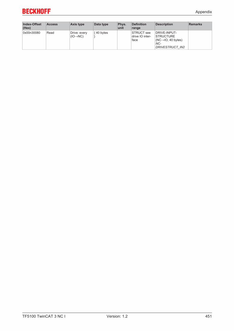
Appendix
TF5100 TwinCAT 3 NC I 451Version: 1.2
Index-Offset(Hex)
Access Axis type Data type Phys.unit
Definitionrange
Description Remarks
0x00n30080 Read Drive: every(IO→NC)
{ 40 bytes}
STRUCT seedrive IO inter-face
DRIVE-INPUT-STRUCTURE(NC→IO, 40 bytes)NC-DRIVESTRUCT_IN2

Appendix
TF5100 TwinCAT 3 NC I452 Version: 1.2
7.8.5 Specification Encoder
7.8.5.1 "Index offset" specification for Encoder parameter (Index group 0x5000 +ID)
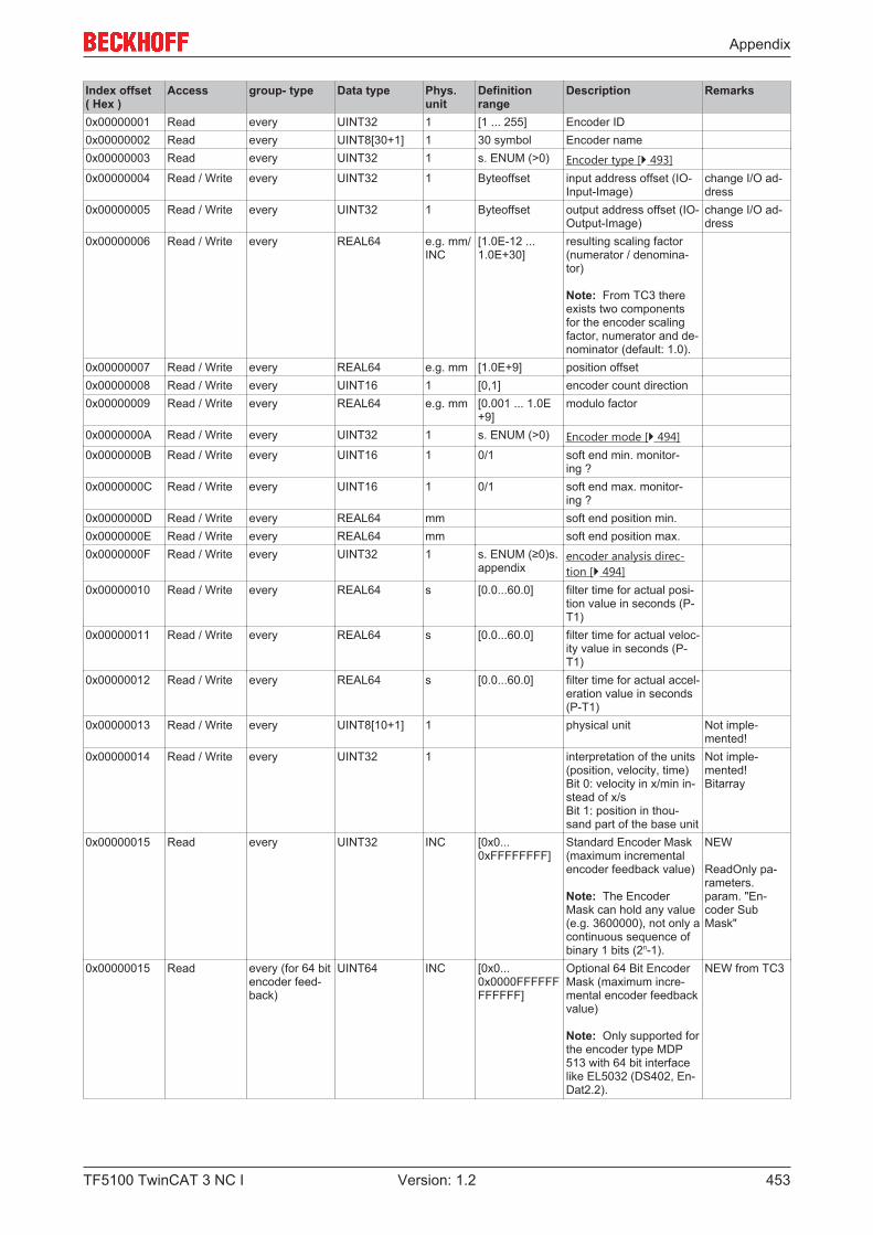
Appendix
TF5100 TwinCAT 3 NC I 453Version: 1.2
Index offset( Hex )
Access group- type Data type Phys.unit
Definitionrange
Description Remarks
0x00000001 Read every UINT32 1 [1 ... 255] Encoder ID0x00000002 Read every UINT8[30+1] 1 30 symbol Encoder name0x00000003 Read every UINT32 1 s. ENUM (>0) Encoder type [} 493]0x00000004 Read / Write every UINT32 1 Byteoffset input address offset (IO-
Input-Image)change I/O ad-dress
0x00000005 Read / Write every UINT32 1 Byteoffset output address offset (IO-Output-Image)
change I/O ad-dress
0x00000006 Read / Write every REAL64 e.g. mm/INC
[1.0E-12 ...1.0E+30]
resulting scaling factor(numerator / denomina-tor)
Note: From TC3 thereexists two componentsfor the encoder scalingfactor, numerator and de-nominator (default: 1.0).
0x00000007 Read / Write every REAL64 e.g. mm [1.0E+9] position offset0x00000008 Read / Write every UINT16 1 [0,1] encoder count direction0x00000009 Read / Write every REAL64 e.g. mm [0.001 ... 1.0E
+9]modulo factor
0x0000000A Read / Write every UINT32 1 s. ENUM (>0) Encoder mode [} 494]0x0000000B Read / Write every UINT16 1 0/1 soft end min. monitor-
ing ?0x0000000C Read / Write every UINT16 1 0/1 soft end max. monitor-
ing ?0x0000000D Read / Write every REAL64 mm soft end position min.0x0000000E Read / Write every REAL64 mm soft end position max.0x0000000F Read / Write every UINT32 1 s. ENUM (≥0)s.
appendixencoder analysis direc-tion [} 494]
0x00000010 Read / Write every REAL64 s [0.0...60.0] filter time for actual posi-tion value in seconds (P-T1)
0x00000011 Read / Write every REAL64 s [0.0...60.0] filter time for actual veloc-ity value in seconds (P-T1)
0x00000012 Read / Write every REAL64 s [0.0...60.0] filter time for actual accel-eration value in seconds(P-T1)
0x00000013 Read / Write every UINT8[10+1] 1 physical unit Not imple-mented!
0x00000014 Read / Write every UINT32 1 interpretation of the units(position, velocity, time)Bit 0: velocity in x/min in-stead of x/sBit 1: position in thou-sand part of the base unit
Not imple-mented!Bitarray
0x00000015 Read every UINT32 INC [0x0...0xFFFFFFFF]
Standard Encoder Mask(maximum incrementalencoder feedback value)
Note: The EncoderMask can hold any value(e.g. 3600000), not only acontinuous sequence ofbinary 1 bits (2n-1).
NEW
ReadOnly pa-rameters.param. "En-coder SubMask"
0x00000015 Read every (for 64 bitencoder feed-back)
UINT64 INC [0x0...0x0000FFFFFFFFFFFF]
Optional 64 Bit EncoderMask (maximum incre-mental encoder feedbackvalue)
Note: Only supported forthe encoder type MDP513 with 64 bit interfacelike EL5032 (DS402, En-Dat2.2).
NEW from TC3
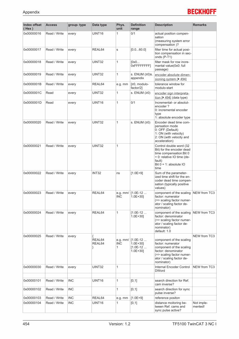
Appendix
TF5100 TwinCAT 3 NC I454 Version: 1.2
Index offset( Hex )
Access group- type Data type Phys.unit
Definitionrange
Description Remarks
0x00000016 Read / Write every UINT16 1 0/1 actual position compen-sation(measuring system errorcompensation )?
0x00000017 Read / Write every REAL64 s [0.0...60.0] filter time for actual posi-tion compensation in sec-onds (P-T1)
0x00000018 Read / Write every UINT32 1 [0x0...0xFFFFFFFF]
filter mask for row incre-mantal value(0x0: fullpassage)
0x00000019 Read / Write every UINT32 1 s. ENUM (≥0)s.appendix
encoder absolute dimen-sioning system [} 494]
0x0000001B Read / Write every REAL64 e.g. mm [≥0, modulo-factor/2]
tolerance window formodulo-start
0x0000001C Read every UINT32 1 s. ENUM (≥0) encoder sign interpreta-tion [} 494] (data type)
0x0000001D Read every UINT16 1 0/1 Incremental- or absolut-encoder ?0: incremental encodertype1: absolute encoder type
0x00000020 Read / Write every UINT32 1 s. ENUM (≥0) Encoder dead time com-pensation mode0: OFF (Default)1: ON (with velocity)2: ON (with velocity andacceleration)
0x00000021 Read / Write every UINT32 1 Control double word (32Bit) for the encoder deadtime compensation:Bit 0= 0: relative IO time (de-fault)Bit 0 = 1: absolute IOtime
0x00000022 Read / Write every INT32 ns [1.0E+9] Sum of the parameter-ized time shift for the en-coder dead time compen-sation (typically positivevalues)
0x00000023 Read / Write every REAL64 e.g. mm/INC
[1.0E-12 ...1.0E+30]
component of the scalingfactor: numerator(=> scaling factor numer-ator / scaling factor de-nominator)
NEW from TC3
0x00000024 Read / Write every REAL64 1 [1.0E-12 ...1.0E+30]
component of the scalingfactor: denominator(=> scaling factor numer-ator / scaling factor de-nominator)default: 1.0
NEW from TC3
0x00000025 Read / Write every {REAL64REAL64}
e.g. mm/INC1
[1.0E-12 ...1.0E+30][1.0E-12 ...1.0E+30]
component of the scalingfactor: numeratorcomponent of the scalingfactor: denominator(=> scaling factor numer-ator / scaling factor de-nominator)
NEW from TC3
0x00000030 Read / Write every UINT32 1 Internal Encoder ControlDWord
NEW from TC3
0x00000101 Read / Write INC UINT16 1 [0,1] search direction for Ref.cam inverse?
0x00000102 Read / Write INC 1 [0,1] search direction for syncpulse inverse?
0x00000103 Read / Write INC REAL64 e.g. mm [1.0E+9] reference positon0x00000104 Read / Write INC UINT16 1 [0,1] distance moitoring be-
tween Ref. cams andsync pulse active?
Not imple-mented!

Appendix
TF5100 TwinCAT 3 NC I 455Version: 1.2
Index offset( Hex )
Access group- type Data type Phys.unit
Definitionrange
Description Remarks
0x00000105 Read / Write INC UINT32 INC [0 ...65536] minimum distance be-tween Ref. cams andsync pulse in increments
Not imple-mented!
0x00000106 Read / Write INC UINT16 1 [0,1] external sync pulse?0x00000107 Read / Write INC UINT32 1 s. ENUM (>0)
s. appendixreference mode [} 495] s.appendix
0x00000108 Read / Write INC UINT32 1 [0x0000000F...0xFFFFFFFF]Bi-nary mask: (2n -1)
Encoder Sub Mask (max-imum incremental valueof the enocder absoluterange)For example used as ref-erence signal for homingwith "Software Sync" orused for the NC RetainData ("ABSOLUTE(MODULO)", "INCRE-MENTAL (SINGLETURNABSOLUTE)" ).
Note 1: The EncoderSub Mask must be lessor equal than the En-coder Mask.Note 2: The EncoderMask must be an integermultiple of the EncoderSub Mask.Note 3: The EncoderSub Mask must be a con-tinuous sequence of bi-nary 1 bits (2n-1); e.g.0x000FFFFF.
NEW
s. param. "En-coder Mask"
0x00000110 Read / Write INC (encodersimulation)
REAL64 1 [0.0 ...1000000.0]
scaling/weight of thenoise part for the simula-tion encoder

Appendix
TF5100 TwinCAT 3 NC I456 Version: 1.2
7.8.5.2 "Index offset" specification for Encoder state (Index group 0x5100 + ID)
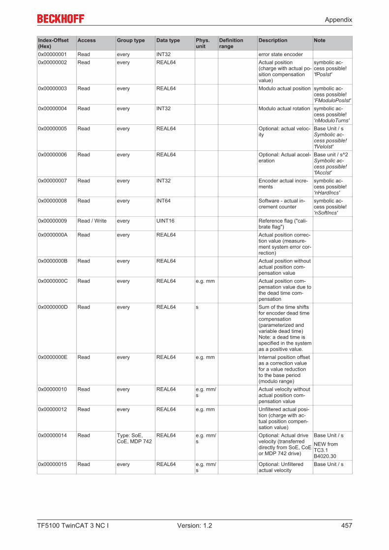
Appendix
TF5100 TwinCAT 3 NC I 457Version: 1.2
Index-Offset(Hex)
Access Group type Data type Phys.unit
Definitionrange
Description Note
0x00000001 Read every INT32 error state encoder0x00000002 Read every REAL64 Actual position
(charge with actual po-sition compensationvalue)
symbolic ac-cess possible!'fPosIst'
0x00000003 Read every REAL64 Modulo actual position symbolic ac-cess possible!'FModuloPosIst'
0x00000004 Read every INT32 Modulo actual rotation symbolic ac-cess possible!'nModuloTurns'
0x00000005 Read every REAL64 Optional: actual veloc-ity
Base Unit / s Symbolic ac-cess possible!'fVeloIst'
0x00000006 Read every REAL64 Optional: Actual accel-eration
Base unit / s^2Symbolic ac-cess possible!'fAccIst'
0x00000007 Read every INT32 Encoder actual incre-ments
symbolic ac-cess possible!'nHardIncs'
0x00000008 Read every INT64 Software - actual in-crement counter
symbolic ac-cess possible!'nSoftIncs'
0x00000009 Read / Write every UINT16 Reference flag ("cali-brate flag")
0x0000000A Read every REAL64 Actual position correc-tion value (measure-ment system error cor-rection)
0x0000000B Read every REAL64 Actual position withoutactual position com-pensation value
0x0000000C Read every REAL64 e.g. mm Actual position com-pensation value due tothe dead time com-pensation
0x0000000D Read every REAL64 s Sum of the time shiftsfor encoder dead timecompensation(parameterized andvariable dead time)Note: a dead time isspecified in the systemas a positive value.
0x0000000E Read every REAL64 e.g. mm Internal position offsetas a correction valuefor a value reductionto the base period(modulo range)
0x00000010 Read every REAL64 e.g. mm/s
Actual velocity withoutactual position com-pensation value
0x00000012 Read every REAL64 e.g. mm Unfiltered actual posi-tion (charge with ac-tual position compen-sation value)
0x00000014 Read Type: SoE,CoE, MDP 742
REAL64 e.g. mm/s
Optional: Actual drivevelocity (transferreddirectly from SoE, CoEor MDP 742 drive)
Base Unit / s
NEW fromTC3.1B4020.30
0x00000015 Read every REAL64 e.g. mm/s
Optional: Unfilteredactual velocity
Base Unit / s

Appendix
TF5100 TwinCAT 3 NC I458 Version: 1.2
Index-Offset(Hex)
Access Group type Data type Phys.unit
Definitionrange
Description Note
0x00000016 Read every READ(16 bytes* N)
Read the actual posi-tion buffer
{UINT32 ns ≥0 DcTimeStamp with 32
bitsUINT32 ReserveREAL64 e.g. mm ±∞ Actual position for the
associated time stamp} [N]
0x00000101 Read INC REAL64 e.g. mm Read back the posi-tion difference be-tween the hardwarelatch being activatedand becoming valid
Cannot betraced by oscil-loscope!
0x00000200 ReadWrite function group"Touch-ProbeV2":-SERCOS/SoE, - EtherCAT/CoE(CANopenDS402) - SoftDrive(TCom), - MDP 511(EL5101,EL5151,EL5021,EL7041,EL7342)
WRITE(24bytes)
read "Touch Probe"state (state of externallatch)
Only for SAF-port 501
{UINT32 1 [1,2,3,4] probe unit (probe 1, 2,
3, 4)UINT32[5] reserved}READ (64bytes){UINT32 1 [0/1] touch probe rising
edge active?UINT32 1 [0/1] touch probe rising
edge became valid?REAL64 e.g. mm touch probe rising
edge position valueUINT32 1 ≥0 touch probe rising
edge counter (continu-ous mode)
UINT32 reservedUINT32 1 [0/1] touch probe falling
edge active?UINT32 1 [0/1] touch probe falling
edge became valid?REAL64 e.g. mm touch probe falling
edge position valueUINT32 1 ≥0 touch probe falling
edge counter (continu-ous mode)
UINT32[5] reserved}
0x00000201 Read KL5101, SERCOS, AX2xxx, ProviDrive
UINT16 1 [0,1] "External latch func-tion" active ?or"Measuring probefunction" active ?(edge-independent)
Cannot betraced by oscil-loscope!
0x00000201 Read CANopen UINT32[4] 1 [0,1] "External latch func-tions 1 to 4" active ?or"Measuring probefunctions 1 to 4" ac-tive ?
Cannot betraced by oscil-loscope!
0x00000202 Read KL5101, SERCOS, AX2xxx, ProviDrive
UINT16 1 [0,1] External latch valuebecame valid?orMeasuring probelatched ? (edge-inde-pendent)
see also Axisinterface NcTo-Plc (status dou-ble word)
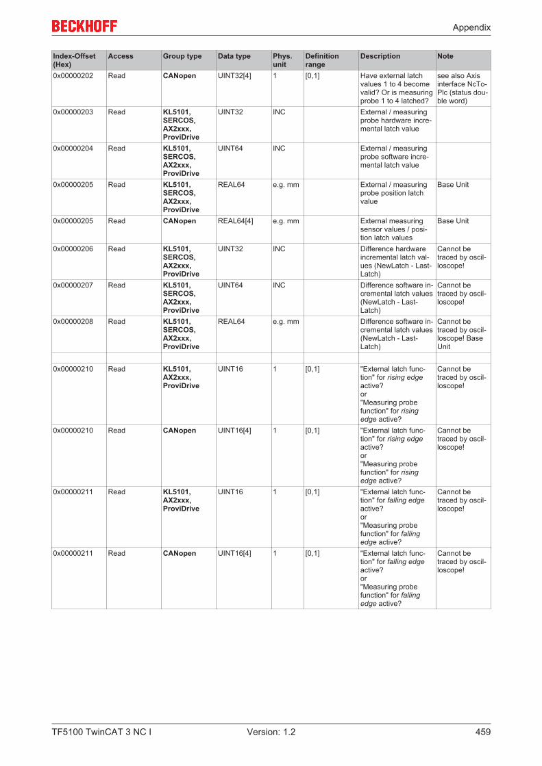
Appendix
TF5100 TwinCAT 3 NC I 459Version: 1.2
Index-Offset(Hex)
Access Group type Data type Phys.unit
Definitionrange
Description Note
0x00000202 Read CANopen UINT32[4] 1 [0,1] Have external latchvalues 1 to 4 becomevalid? Or is measuringprobe 1 to 4 latched?
see also Axisinterface NcTo-Plc (status dou-ble word)
0x00000203 Read KL5101, SERCOS, AX2xxx, ProviDrive
UINT32 INC External / measuringprobe hardware incre-mental latch value
0x00000204 Read KL5101, SERCOS, AX2xxx, ProviDrive
UINT64 INC External / measuringprobe software incre-mental latch value
0x00000205 Read KL5101, SERCOS, AX2xxx, ProviDrive
REAL64 e.g. mm External / measuringprobe position latchvalue
Base Unit
0x00000205 Read CANopen REAL64[4] e.g. mm External measuringsensor values / posi-tion latch values
Base Unit
0x00000206 Read KL5101, SERCOS, AX2xxx, ProviDrive
UINT32 INC Difference hardwareincremental latch val-ues (NewLatch - Last-Latch)
Cannot betraced by oscil-loscope!
0x00000207 Read KL5101, SERCOS, AX2xxx, ProviDrive
UINT64 INC Difference software in-cremental latch values(NewLatch - Last-Latch)
Cannot betraced by oscil-loscope!
0x00000208 Read KL5101, SERCOS, AX2xxx, ProviDrive
REAL64 e.g. mm Difference software in-cremental latch values(NewLatch - Last-Latch)
Cannot betraced by oscil-loscope! BaseUnit
0x00000210 Read KL5101, AX2xxx, ProviDrive
UINT16 1 [0,1] "External latch func-tion" for rising edgeactive? or"Measuring probefunction" for risingedge active?
Cannot betraced by oscil-loscope!
0x00000210 Read CANopen UINT16[4] 1 [0,1] "External latch func-tion" for rising edgeactive? or"Measuring probefunction" for risingedge active?
Cannot betraced by oscil-loscope!
0x00000211 Read KL5101, AX2xxx, ProviDrive
UINT16 1 [0,1] "External latch func-tion" for falling edgeactive? or"Measuring probefunction" for fallingedge active?
Cannot betraced by oscil-loscope!
0x00000211 Read CANopen UINT16[4] 1 [0,1] "External latch func-tion" for falling edgeactive? or"Measuring probefunction" for fallingedge active?
Cannot betraced by oscil-loscope!
Appendix
TF5100 TwinCAT 3 NC I460 Version: 1.2
7.8.5.3 "Index offset" specification for Encoder functions (Index group 0x5200 +ID)
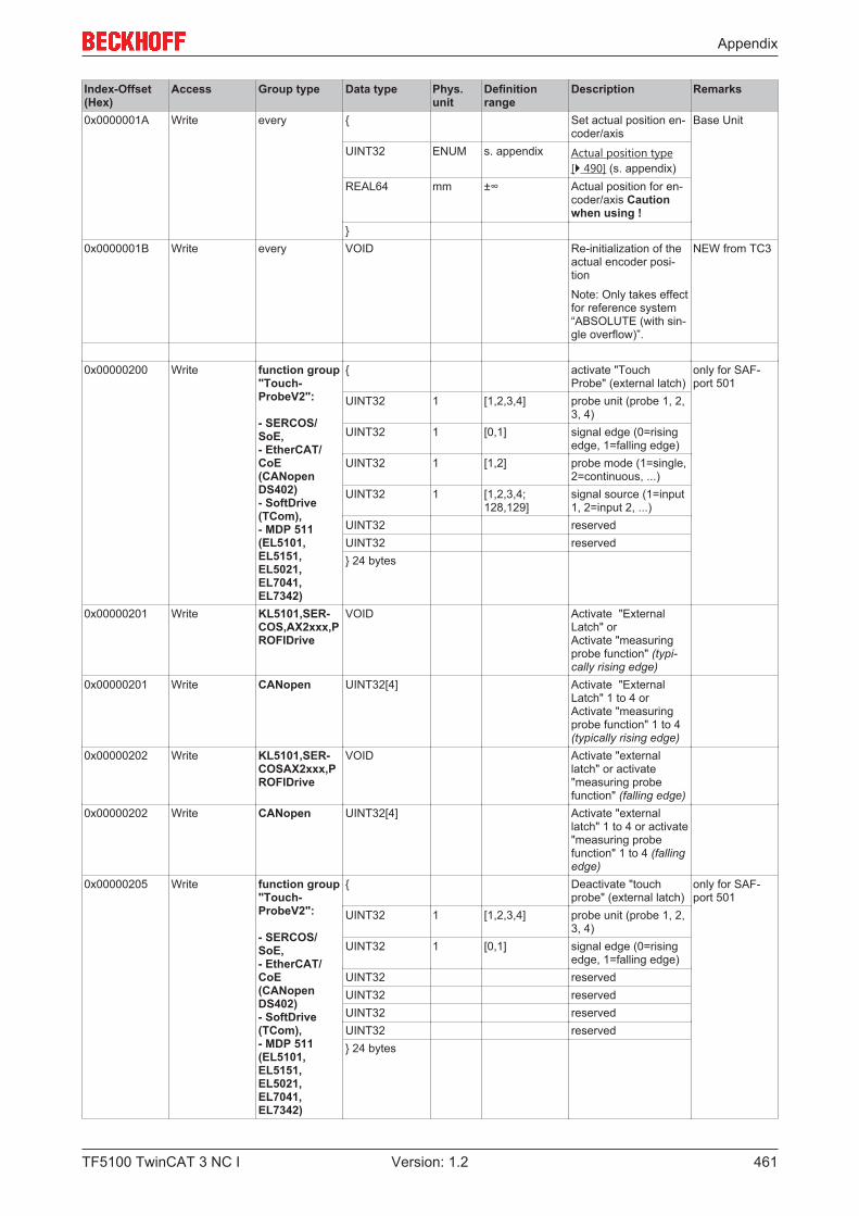
Appendix
TF5100 TwinCAT 3 NC I 461Version: 1.2
Index-Offset(Hex)
Access Group type Data type Phys.unit
Definitionrange
Description Remarks
0x0000001A Write every { Set actual position en-coder/axis
Base Unit
UINT32 ENUM s. appendix Actual position type[} 490] (s. appendix)
REAL64 mm ±∞ Actual position for en-coder/axis Cautionwhen using !
}0x0000001B Write every VOID Re-initialization of the
actual encoder posi-tion
Note: Only takes effectfor reference system“ABSOLUTE (with sin-gle overflow)”.
NEW from TC3
0x00000200 Write function group"Touch-ProbeV2":
- SERCOS/SoE,- EtherCAT/CoE(CANopenDS402) - SoftDrive(TCom),- MDP 511(EL5101,EL5151,EL5021,EL7041,EL7342)
{ activate "TouchProbe" (external latch)
only for SAF-port 501
UINT32 1 [1,2,3,4] probe unit (probe 1, 2,3, 4)
UINT32 1 [0,1] signal edge (0=risingedge, 1=falling edge)
UINT32 1 [1,2] probe mode (1=single,2=continuous, ...)
UINT32 1 [1,2,3,4;128,129]
signal source (1=input1, 2=input 2, ...)
UINT32 reservedUINT32 reserved} 24 bytes
0x00000201 Write KL5101,SER-COS,AX2xxx,PROFIDrive
VOID Activate "ExternalLatch" orActivate "measuringprobe function" (typi-cally rising edge)
0x00000201 Write CANopen UINT32[4] Activate "ExternalLatch" 1 to 4 orActivate "measuringprobe function" 1 to 4(typically rising edge)
0x00000202 Write KL5101,SER-COSAX2xxx,PROFIDrive
VOID Activate "externallatch" or activate"measuring probefunction" (falling edge)
0x00000202 Write CANopen UINT32[4] Activate "externallatch" 1 to 4 or activate"measuring probefunction" 1 to 4 (fallingedge)
0x00000205 Write function group"Touch-ProbeV2":
- SERCOS/SoE,- EtherCAT/CoE(CANopenDS402) - SoftDrive(TCom),- MDP 511(EL5101,EL5151,EL5021,EL7041,EL7342)
{ Deactivate "touchprobe" (external latch)
only for SAF-port 501
UINT32 1 [1,2,3,4] probe unit (probe 1, 2,3, 4)
UINT32 1 [0,1] signal edge (0=risingedge, 1=falling edge)
UINT32 reservedUINT32 reservedUINT32 reservedUINT32 reserved} 24 bytes
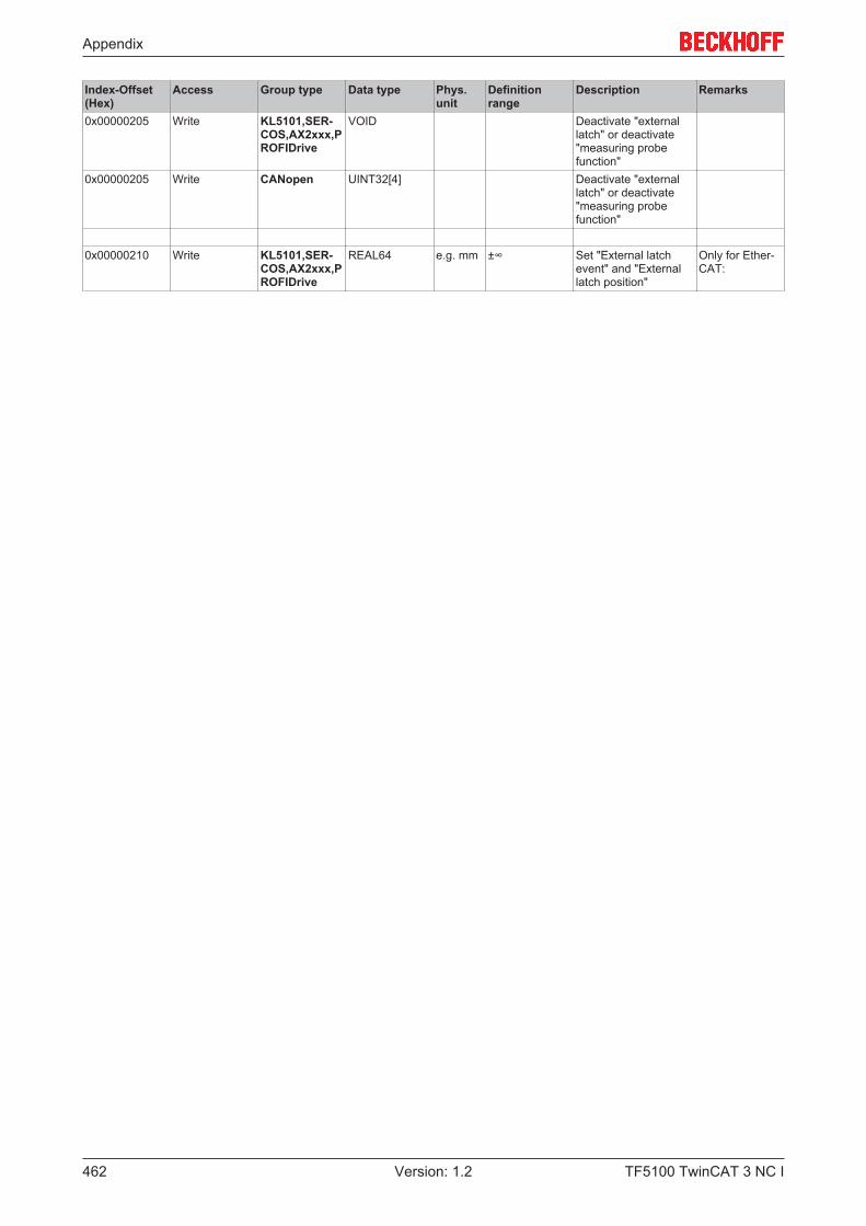
Appendix
TF5100 TwinCAT 3 NC I462 Version: 1.2
Index-Offset(Hex)
Access Group type Data type Phys.unit
Definitionrange
Description Remarks
0x00000205 Write KL5101,SER-COS,AX2xxx,PROFIDrive
VOID Deactivate "externallatch" or deactivate"measuring probefunction"
0x00000205 Write CANopen UINT32[4] Deactivate "externallatch" or deactivate"measuring probefunction"
0x00000210 Write KL5101,SER-COS,AX2xxx,PROFIDrive
REAL64 e.g. mm ±∞ Set "External latchevent" and "Externallatch position"
Only for Ether-CAT:

Appendix
TF5100 TwinCAT 3 NC I 463Version: 1.2
7.8.5.4 "Index offset" specification for cyclic Encoder process data (Index group0x5300 + ID)
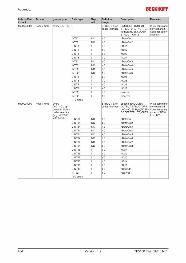
Appendix
TF5100 TwinCAT 3 NC I464 Version: 1.2
Index offset( Hex )
Access group- type Data type Phys.unit
Definitionrange
Description Remarks
0x00000000 Read / Write every (NC→IO) { STRUCT s. en-coder-interface
ENCODER-OUTPUT-STRUCTURE (NC→IO,40 Byte)NCENCODER-STRUCT_OUT2
Write commandonly optional!Consider safetyaspects !
INT32 INC ≥ 0 nDataOut1INT32 INC ≥ 0 nDataOut2UINT8 1 ≥ 0 nCtrl1UINT8 1 ≥ 0 nCtrl2UINT8 1 ≥ 0 nCtrl3UINT8 1 ≥ 0 nCtrl4INT32 INC ≥ 0 nDataOut3INT32 INC ≥ 0 nDataOut4INT32 INC ≥ 0 nDataOut5INT32 INC ≥ 0 nDataOut6UINT8 1 ≥ 0 nCtrl5UINT8 1 ≥ 0 nCtrl6UINT8 1 ≥ 0 nCtrl7UINT8 1 ≥ 0 nCtrl8INT32 1 ≥ 0 reservedINT32 1 ≥ 0 reserved} 40 bytes
0x00000000 Read / Write every(NC→IO), op-tional 64 bit en-coder interface(e.g. MDP513with 64Bit)
{ STRUCT s. en-coder-interface
optional ENCODER-OUTPUT-STRUCTURE(NC→IO, 80 Byte)NCEN-CODERSTRUCT_OUT3
Write commandonly optional!Consider safetyaspects !NEWfrom TC3
UINT64 INC ≥ 0 nDataOut1UINT64 INC ≥ 0 nDataOut2UINT64 INC ≥ 0 nDataOut3UINT64 INC ≥ 0 nDataOut4UINT64 INC ≥ 0 nDataOut5UINT64 INC ≥ 0 nDataOut6UINT64 INC ≥ 0 nDataOut7UINT64 INC ≥ 0 nDataOut8UINT16 1 ≥ 0 nCtrl1UINT16 1 ≥ 0 nCtrl2UINT16 1 ≥ 0 nCtrl3UINT16 1 ≥ 0 nCtrl4UINT16 1 ≥ 0 nCtrl5UINT16 1 ≥ 0 nComCtrlINT32 1 ≥ 0 reserved} 80 bytes
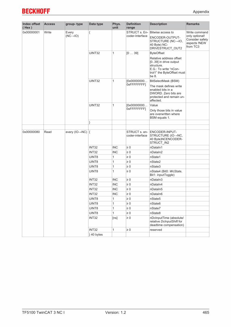
Appendix
TF5100 TwinCAT 3 NC I 465Version: 1.2
Index offset( Hex )
Access group- type Data type Phys.unit
Definitionrange
Description Remarks
0x00000001 Write Every(NC→IO)
{ STRUCT s. En-coder-Interface
Bitwise access to
ENCODER-OUTPUT-STRUCTURE (NC→IO,40 Byte) NC-DRIVESTRUCT_OUT2
Write commandonly optional!Consider safetyaspects !NEWfrom TC3
UINT32 1 [0 … 39] ByteOffset
Relative address offset[0..39] in drive outputstructure. E.G.: To write “nCon-trol1” the ByteOffset mustbe 8.
UINT32 1 [0x00000000…0xFFFFFFFF]
BitSelectMask (BSM)
The mask defines writeenabled bits in aDWORD. Zero bits areprotected and remain un-affected.
UINT32 1 [0x00000000…0xFFFFFFFF]
Value
Only those bits in valueare overwritten whereBSM equals 1.
}
0x00000080 Read every (IO→NC) { STRUCT s. en-coder-interface
ENCODER-INPUT-STRUCTURE (IO→NC,40 Byte)NCENCODER-STRUCT_IN2
INT32 INC ≥ 0 nDataIn1INT32 INC ≥ 0 nDataIn2UINT8 1 ≥ 0 nState1UINT8 1 ≥ 0 nState2UINT8 1 ≥ 0 nState3UINT8 1 ≥ 0 nState4 (Bit0: WcState,
Bit1: InputToggle)INT32 INC ≥ 0 nDataIn3INT32 INC ≥ 0 nDataIn4INT32 INC ≥ 0 nDataIn5INT32 INC ≥ 0 nDataIn6UINT8 1 ≥ 0 nState5UINT8 1 ≥ 0 nState6UINT8 1 ≥ 0 nState7UINT8 1 ≥ 0 nState8INT32 [ns] ≥ 0 nDcInputTime (absolute/
relative DcInputShift fordeadtime compensation)
INT32 1 ≥ 0 reserved} 40 bytes
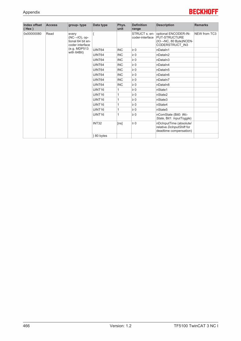
Appendix
TF5100 TwinCAT 3 NC I466 Version: 1.2
Index offset( Hex )
Access group- type Data type Phys.unit
Definitionrange
Description Remarks
0x00000080 Read every(NC→IO), op-tional 64 bit en-coder interface(e.g. MDP513with 64Bit)
{ STRUCT s. en-coder-interface
optional ENCODER-IN-PUT-STRUCTURE(IO→NC, 80 Byte)NCEN-CODERSTRUCT_IN3
NEW from TC3
UINT64 INC ≥ 0 nDataIn1UINT64 INC ≥ 0 nDataIn2UINT64 INC ≥ 0 nDataIn3UINT64 INC ≥ 0 nDataIn4UINT64 INC ≥ 0 nDataIn5UINT64 INC ≥ 0 nDataIn6UINT64 INC ≥ 0 nDataIn7UINT64 INC ≥ 0 nDataIn8UINT16 1 ≥ 0 nState1UINT16 1 ≥ 0 nState2UINT16 1 ≥ 0 nState3UINT16 1 ≥ 0 nState4UINT16 1 ≥ 0 nState5UINT16 1 ≥ 0 nComState (Bit0: Wc-
State, Bit1: InputToggle)INT32 [ns] ≥ 0 nDcInputTime (absolute/
relative DcInputShift fordeadtime compensation)
} 80 bytes
Appendix
TF5100 TwinCAT 3 NC I 467Version: 1.2
7.8.6 Specification Controller
7.8.6.1 "Index offset" specification for Controller parameter (Index group 0x6000+ ID)
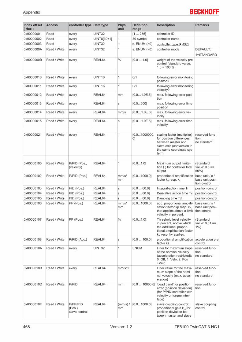
Appendix
TF5100 TwinCAT 3 NC I468 Version: 1.2
Index offset( Hex )
Access controller type Data type Phys.unit
Definitionrange
Description Remarks
0x00000001 Read every UINT32 1 [1 ... 255] controller ID0x00000002 Read every UINT8[30+1] 1 30 symbol controller name0x00000003 Read every UINT32 1 s. ENUM (>0) controller type [} 492]0x0000000A Read / Write every UINT32 1 s. ENUM (>0) controller mode DEFAULT:
1=STANDARD0x0000000B Read / Write every REAL64 % [0.0 ... 1.0] weight of the velocity pre
control (standard value:1.0 = 100 %)
0x00000010 Read / Write every UINT16 1 0/1 following error monitoringpositon?
0x00000011 Read / Write every UINT16 1 0/1 following error monitoringvelocity?
0x00000012 Read / Write every REAL64 mm [0.0…1.0E.6] max. following error posi-tion
0x00000013 Read / Write every REAL64 s [0.0...600] max. following error timeposition
0x00000014 Read / Write every REAL64 mm/s [0.0…1.0E.6] max. following error ve-locity
0x00000015 Read / Write every REAL64 s [0.0…1.0E.6] max. following error timevelocity
0x00000021 Read / Write every REAL64 1 [0.0...1000000.0]
scaling factor (multiplier)for position differencesbetween master andslave axis (conversion inthe same coordinate sys-tem)
reserved func-tion,no standard!
0x00000100 Read / Write P/PID (Pos.,(velocity)
REAL64 1 [0.0...1.0] Maximum output limita-tion ( ) for controller totaloutput
(Standardvalue: 0.5 ==50%)
0x00000102 Read / Write P/PID (Pos.) REAL64 mm/s/mm
[0.0...1000.0] proportional amplificationfactor kp resp. kv
base unit / s /base unit posi-tion control
0x00000103 Read / Write PID (Pos.) REAL64 s [0.0 ... 60.0] Integral-action time Tn position control0x00000104 Read / Write PID (Pos.) REAL64 s [0.0 ... 60.0] Derivative action time Tv position control0x00000105 Read / Write PID (Pos.) REAL64 s [0.0 ... 60.0] Damping time Td position control0x00000106 Read / Write PP (Pos.) REAL64 mm/s/
mm[0.0...1000.0] add. proportional amplifi-
cation factor kp resp. kv,that applies above a limitvelocity in percent.
base unit / s /base unit posi-tion control
0x00000107 Read / Write PP (Pos.) REAL64 % [0.0...1.0] Threshold level velocityin percent, above whichthe additional propor-tional amplification factorkp resp. kv applies.
(Standardvalue: 0.01 ==1%)
0x00000108 Read / Write P/PID (Acc.) REAL64 s [0.0 ... 100.0] proportional amplificationfactor ka
acceleration precontrol
0x0000010A Read / Write every UINT32 1 ENUM Filter for maximum slopeof the nominal velocity(acceleration restricted):0: Off, 1: Velo, 2: Pos+Velo
reserved func-tion,no standard!
0x0000010B Read / Write every REAL64 mm/s^2 Filter value for the maxi-mum slope of the nomi-nal velocity (max. accel-eration)
reserved func-tion,no standard!
0x0000010D Read / Write P/PID REAL64 mm [0.0 ... 10000.0] 'dead band' for positionerror (position deviation)(for P/PID-controller withvelocity or torque inter-face)
reserved func-tion
0x0000010F Read / Write P/PP/PID(Pos.)slave-control
REAL64 (mm/s) /mm
[0.0...1000.0] slave coupling control:proportional gain kcp forposition deviation be-tween master and slave
slave couplingcontrol
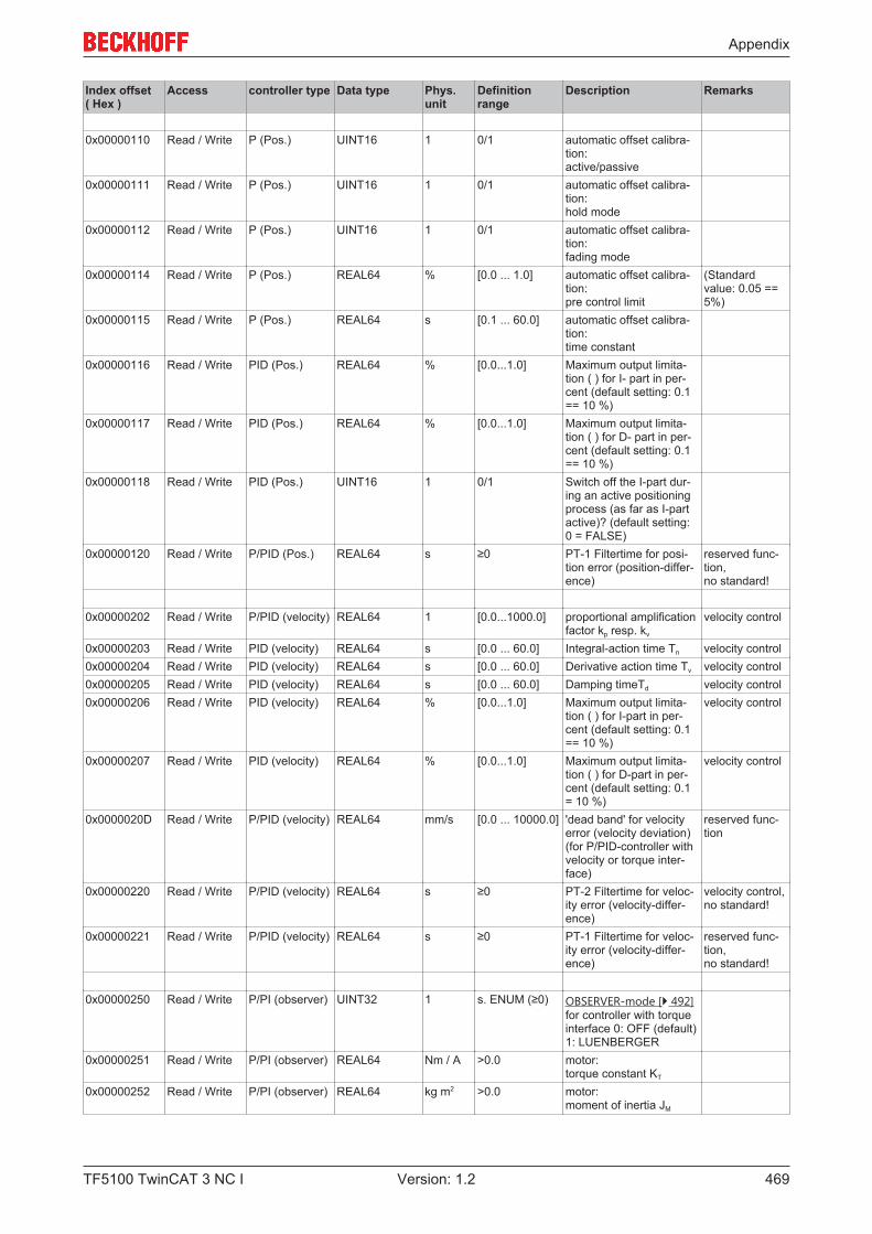
Appendix
TF5100 TwinCAT 3 NC I 469Version: 1.2
Index offset( Hex )
Access controller type Data type Phys.unit
Definitionrange
Description Remarks
0x00000110 Read / Write P (Pos.) UINT16 1 0/1 automatic offset calibra-tion:active/passive
0x00000111 Read / Write P (Pos.) UINT16 1 0/1 automatic offset calibra-tion: hold mode
0x00000112 Read / Write P (Pos.) UINT16 1 0/1 automatic offset calibra-tion: fading mode
0x00000114 Read / Write P (Pos.) REAL64 % [0.0 ... 1.0] automatic offset calibra-tion: pre control limit
(Standardvalue: 0.05 ==5%)
0x00000115 Read / Write P (Pos.) REAL64 s [0.1 ... 60.0] automatic offset calibra-tion:time constant
0x00000116 Read / Write PID (Pos.) REAL64 % [0.0...1.0] Maximum output limita-tion ( ) for I- part in per-cent (default setting: 0.1== 10 %)
0x00000117 Read / Write PID (Pos.) REAL64 % [0.0...1.0] Maximum output limita-tion ( ) for D- part in per-cent (default setting: 0.1== 10 %)
0x00000118 Read / Write PID (Pos.) UINT16 1 0/1 Switch off the I-part dur-ing an active positioningprocess (as far as I-partactive)? (default setting:0 = FALSE)
0x00000120 Read / Write P/PID (Pos.) REAL64 s ≥0 PT-1 Filtertime for posi-tion error (position-differ-ence)
reserved func-tion,no standard!
0x00000202 Read / Write P/PID (velocity) REAL64 1 [0.0...1000.0] proportional amplificationfactor kp resp. kv
velocity control
0x00000203 Read / Write PID (velocity) REAL64 s [0.0 ... 60.0] Integral-action time Tn velocity control0x00000204 Read / Write PID (velocity) REAL64 s [0.0 ... 60.0] Derivative action time Tv velocity control0x00000205 Read / Write PID (velocity) REAL64 s [0.0 ... 60.0] Damping timeTd velocity control0x00000206 Read / Write PID (velocity) REAL64 % [0.0...1.0] Maximum output limita-
tion ( ) for I-part in per-cent (default setting: 0.1== 10 %)
velocity control
0x00000207 Read / Write PID (velocity) REAL64 % [0.0...1.0] Maximum output limita-tion ( ) for D-part in per-cent (default setting: 0.1= 10 %)
velocity control
0x0000020D Read / Write P/PID (velocity) REAL64 mm/s [0.0 ... 10000.0] 'dead band' for velocityerror (velocity deviation)(for P/PID-controller withvelocity or torque inter-face)
reserved func-tion
0x00000220 Read / Write P/PID (velocity) REAL64 s ≥0 PT-2 Filtertime for veloc-ity error (velocity-differ-ence)
velocity control,no standard!
0x00000221 Read / Write P/PID (velocity) REAL64 s ≥0 PT-1 Filtertime for veloc-ity error (velocity-differ-ence)
reserved func-tion,no standard!
0x00000250 Read / Write P/PI (observer) UINT32 1 s. ENUM (≥0) OBSERVER-mode [} 492]for controller with torqueinterface 0: OFF (default)1: LUENBERGER
0x00000251 Read / Write P/PI (observer) REAL64 Nm / A >0.0 motor:torque constant KT
0x00000252 Read / Write P/PI (observer) REAL64 kg m2 >0.0 motor:moment of inertia JM
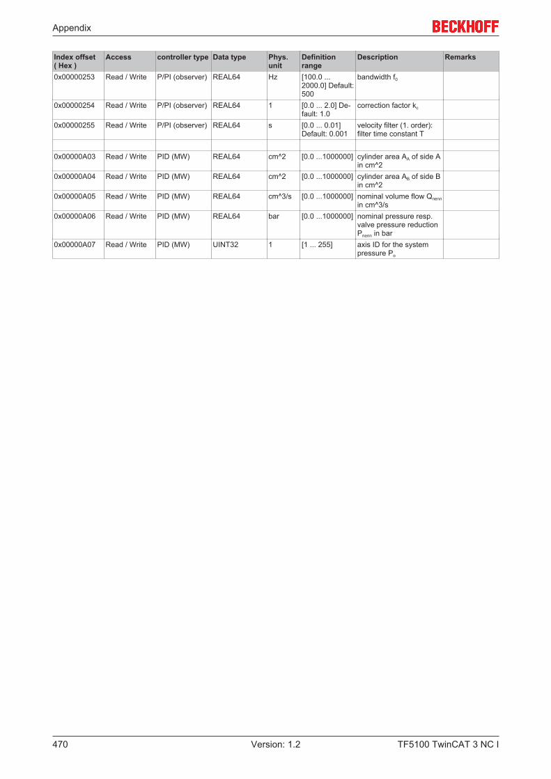
Appendix
TF5100 TwinCAT 3 NC I470 Version: 1.2
Index offset( Hex )
Access controller type Data type Phys.unit
Definitionrange
Description Remarks
0x00000253 Read / Write P/PI (observer) REAL64 Hz [100.0 ...2000.0] Default:500
bandwidth f0
0x00000254 Read / Write P/PI (observer) REAL64 1 [0.0 ... 2.0] De-fault: 1.0
correction factor kc
0x00000255 Read / Write P/PI (observer) REAL64 s [0.0 ... 0.01]Default: 0.001
velocity filter (1. order):filter time constant T
0x00000A03 Read / Write PID (MW) REAL64 cm^2 [0.0 ...1000000] cylinder area AA of side Ain cm^2
0x00000A04 Read / Write PID (MW) REAL64 cm^2 [0.0 ...1000000] cylinder area AB of side Bin cm^2
0x00000A05 Read / Write PID (MW) REAL64 cm^3/s [0.0 ...1000000] nominal volume flow Qnennin cm^3/s
0x00000A06 Read / Write PID (MW) REAL64 bar [0.0 ...1000000] nominal pressure resp.valve pressure reductionPnenn in bar
0x00000A07 Read / Write PID (MW) UINT32 1 [1 ... 255] axis ID for the systempressure Po
Appendix
TF5100 TwinCAT 3 NC I 471Version: 1.2
7.8.6.2 "Index offset" specification for Controller state (Index group 0x6100 + ID)
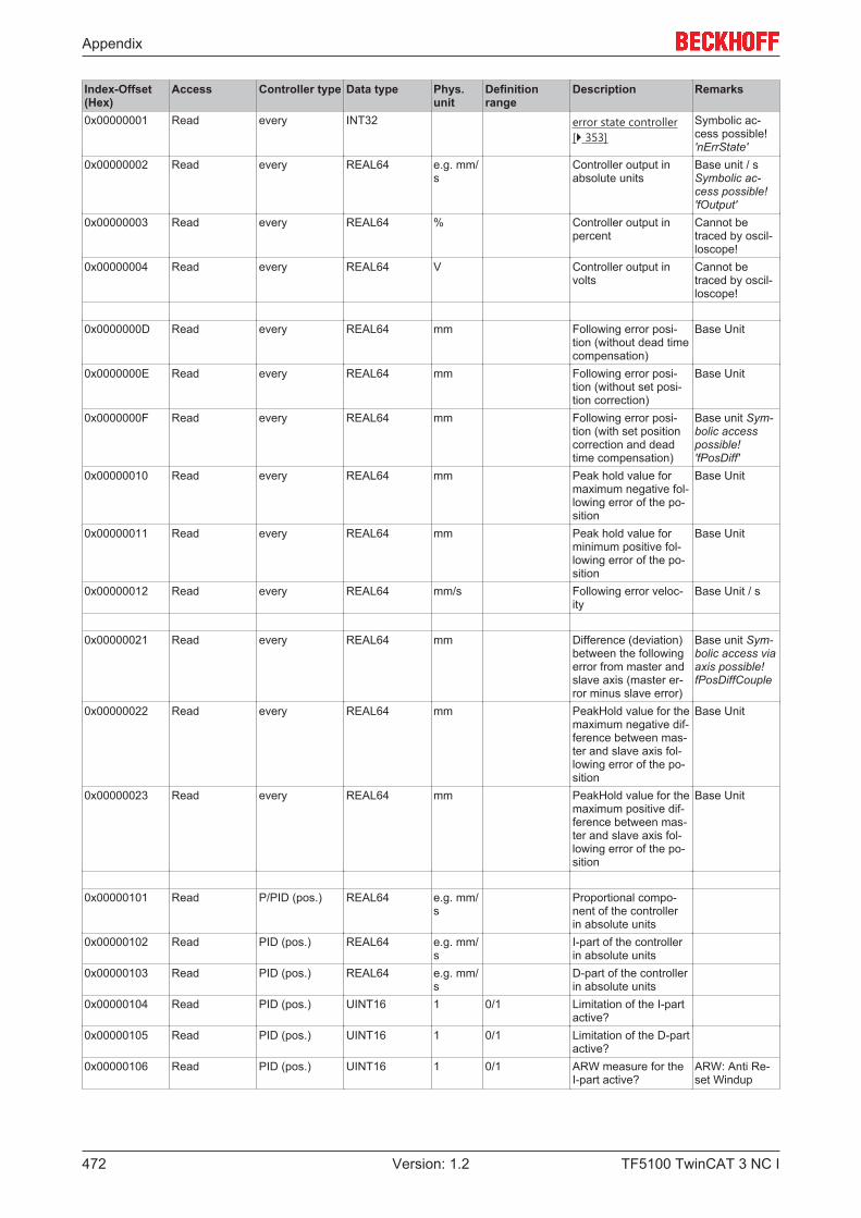
Appendix
TF5100 TwinCAT 3 NC I472 Version: 1.2
Index-Offset(Hex)
Access Controller type Data type Phys.unit
Definitionrange
Description Remarks
0x00000001 Read every INT32 error state controller[} 353]
Symbolic ac-cess possible!'nErrState'
0x00000002 Read every REAL64 e.g. mm/s
Controller output inabsolute units
Base unit / sSymbolic ac-cess possible!'fOutput'
0x00000003 Read every REAL64 % Controller output inpercent
Cannot betraced by oscil-loscope!
0x00000004 Read every REAL64 V Controller output involts
Cannot betraced by oscil-loscope!
0x0000000D Read every REAL64 mm Following error posi-tion (without dead timecompensation)
Base Unit
0x0000000E Read every REAL64 mm Following error posi-tion (without set posi-tion correction)
Base Unit
0x0000000F Read every REAL64 mm Following error posi-tion (with set positioncorrection and deadtime compensation)
Base unit Sym-bolic accesspossible!'fPosDiff'
0x00000010 Read every REAL64 mm Peak hold value formaximum negative fol-lowing error of the po-sition
Base Unit
0x00000011 Read every REAL64 mm Peak hold value forminimum positive fol-lowing error of the po-sition
Base Unit
0x00000012 Read every REAL64 mm/s Following error veloc-ity
Base Unit / s
0x00000021 Read every REAL64 mm Difference (deviation)between the followingerror from master andslave axis (master er-ror minus slave error)
Base unit Sym-bolic access viaaxis possible! fPosDiffCouple
0x00000022 Read every REAL64 mm PeakHold value for themaximum negative dif-ference between mas-ter and slave axis fol-lowing error of the po-sition
Base Unit
0x00000023 Read every REAL64 mm PeakHold value for themaximum positive dif-ference between mas-ter and slave axis fol-lowing error of the po-sition
Base Unit
0x00000101 Read P/PID (pos.) REAL64 e.g. mm/s
Proportional compo-nent of the controllerin absolute units
0x00000102 Read PID (pos.) REAL64 e.g. mm/s
I-part of the controllerin absolute units
0x00000103 Read PID (pos.) REAL64 e.g. mm/s
D-part of the controllerin absolute units
0x00000104 Read PID (pos.) UINT16 1 0/1 Limitation of the I-partactive?
0x00000105 Read PID (pos.) UINT16 1 0/1 Limitation of the D-partactive?
0x00000106 Read PID (pos.) UINT16 1 0/1 ARW measure for theI-part active?
ARW: Anti Re-set Windup

Appendix
TF5100 TwinCAT 3 NC I 473Version: 1.2
Index-Offset(Hex)
Access Controller type Data type Phys.unit
Definitionrange
Description Remarks
0x0000010F Read P/PP/PID (ve-loc.)
REAL64 e.g. mm/s
Proportion of auto-matic offset compen-sation in absoluteunits
NEW
0x00000110 Read PID (pos.) REAL64 e.g. mm/s
Acceleration pre-con-trol Yacc of the con-troller in absoluteunits, note: Functiondepends on controllertype!
accelerationpre-control
0x00000111 Read PP (Pos.) REAL64 mm/s/mm
≥0 Internal interpolatedproportional gain kp orkv
PP controller
0x0000011A0x0000011B0x0000011C0x0000011D0x0000011E0x0000011F0x000001200x000001210x000001220x000001230x00000124
Read P (Pos.) UINT32REAL64REAL64REAL64REAL64REAL64REAL64REAL64REAL64REAL64REAL64
1mmmm/smm/smm/s^2mmmmmm/smm/s^2mm/smm/s^2
Set velocity filter: In-ternalPhaseInternalPosSollError !TestVeloSetInternalLimited-VeloSollInternalAccSollRelInternalPosSollRelPosSetCorrected !VeloSetCorrected !AccSollCorrected !TestVeloSetCorrectedTestAccSetCorrected
List! Reservedfunction,no standard!
0x00000201 Read P,PID (velocity) REAL64 e.g. mm/s
Velocity part of thecontroller
Base Unit / s
0x00000202 Read P,PID (velocity) REAL64 % Velocity part of thecontroller in percent
Cannot betraced by oscil-loscope!
0x00000203 Read P,PID (velocity) REAL64 V Velocity part of thecontroller in volts
Cannot betraced by oscil-loscope!
0x00000201 Read P/PID (velocity) REAL64 e.g. mm/s
Proportional compo-nent of the controllerin absolute units
0x00000202 Read P/PID (velocity) REAL64 e.g. mm/s
I-part of the controllerin absolute units
0x00000203 Read P/PID (velocity) REAL64 e.g. mm/s
D-part of the controllerin absolute units
0x00000204 Read P/PID (velocity) UINT16 1 0/1 Limitation of the I-partactive?
0x00000205 Read P/PID (velocity) UINT16 1 0/1 Limitation of the D-partactive?
0x00000206 Read P/PID (velocity) UINT16 1 0/1 ARW measure for theI-part active?
ARW: Anti Re-set Windup
0x0000020A Read P/PID (velocity) REAL64 e.g. mm/s
Total input size of thevelocity controller
0x00000250 Read P/PI (observer) REAL64 e.g. mm Observer: Position dif-ference (actual posi-tion - observer position
0x00000251 Read P/PI (observer) REAL64 e.g. mm Observer: Position
0x00000252 Read P/PI (observer) REAL64 e.g. mm/s
Observer: Velocity 2(for proportional com-ponent)
0x00000253 Read P/PI (observer) REAL64 e.g. mm/s
Observer: Velocity 1(for I-part)
0x00000254 Read P/PI (observer) REAL64 e.g. mm/s^2
Observer: Accelera-tion
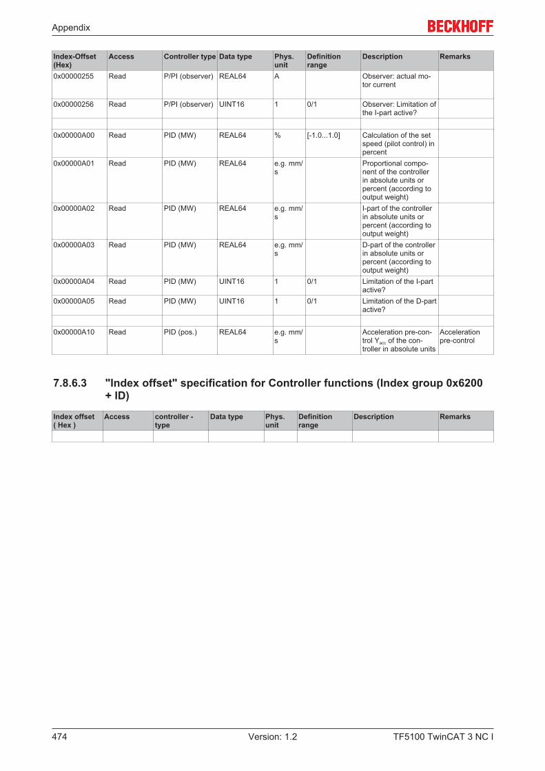
Appendix
TF5100 TwinCAT 3 NC I474 Version: 1.2
Index-Offset(Hex)
Access Controller type Data type Phys.unit
Definitionrange
Description Remarks
0x00000255 Read P/PI (observer) REAL64 A Observer: actual mo-tor current
0x00000256 Read P/PI (observer) UINT16 1 0/1 Observer: Limitation ofthe I-part active?
0x00000A00 Read PID (MW) REAL64 % [-1.0...1.0] Calculation of the setspeed (pilot control) inpercent
0x00000A01 Read PID (MW) REAL64 e.g. mm/s
Proportional compo-nent of the controllerin absolute units orpercent (according tooutput weight)
0x00000A02 Read PID (MW) REAL64 e.g. mm/s
I-part of the controllerin absolute units orpercent (according tooutput weight)
0x00000A03 Read PID (MW) REAL64 e.g. mm/s
D-part of the controllerin absolute units orpercent (according tooutput weight)
0x00000A04 Read PID (MW) UINT16 1 0/1 Limitation of the I-partactive?
0x00000A05 Read PID (MW) UINT16 1 0/1 Limitation of the D-partactive?
0x00000A10 Read PID (pos.) REAL64 e.g. mm/s
Acceleration pre-con-trol Yacc of the con-troller in absolute units
Accelerationpre-control
7.8.6.3 "Index offset" specification for Controller functions (Index group 0x6200+ ID)
Index offset( Hex )
Access controller -type
Data type Phys.unit
Definitionrange
Description Remarks
Appendix
TF5100 TwinCAT 3 NC I 475Version: 1.2
7.8.7 Specification Drive
7.8.7.1 "Index offset" specification for Drive parameter (Index group 0x7000 + ID)
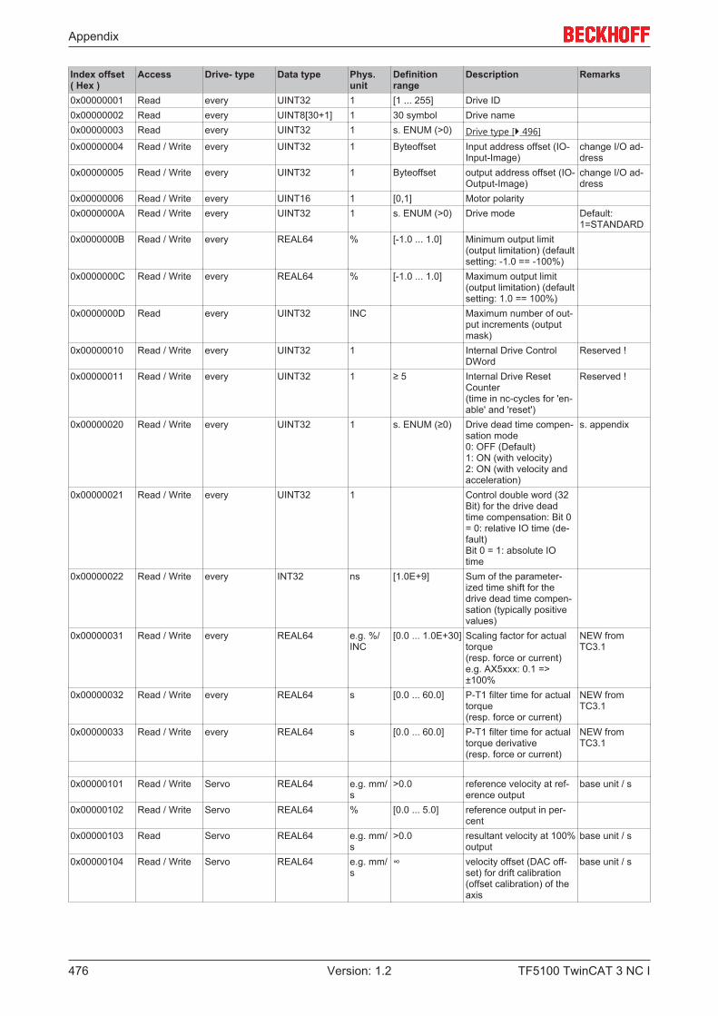
Appendix
TF5100 TwinCAT 3 NC I476 Version: 1.2
Index offset( Hex )
Access Drive- type Data type Phys.unit
Definitionrange
Description Remarks
0x00000001 Read every UINT32 1 [1 ... 255] Drive ID0x00000002 Read every UINT8[30+1] 1 30 symbol Drive name0x00000003 Read every UINT32 1 s. ENUM (>0) Drive type [} 496]0x00000004 Read / Write every UINT32 1 Byteoffset Input address offset (IO-
Input-Image)change I/O ad-dress
0x00000005 Read / Write every UINT32 1 Byteoffset output address offset (IO-Output-Image)
change I/O ad-dress
0x00000006 Read / Write every UINT16 1 [0,1] Motor polarity0x0000000A Read / Write every UINT32 1 s. ENUM (>0) Drive mode Default:
1=STANDARD0x0000000B Read / Write every REAL64 % [-1.0 ... 1.0] Minimum output limit
(output limitation) (defaultsetting: -1.0 == -100%)
0x0000000C Read / Write every REAL64 % [-1.0 ... 1.0] Maximum output limit(output limitation) (defaultsetting: 1.0 == 100%)
0x0000000D Read every UINT32 INC Maximum number of out-put increments (outputmask)
0x00000010 Read / Write every UINT32 1 Internal Drive ControlDWord
Reserved !
0x00000011 Read / Write every UINT32 1 ≥ 5 Internal Drive ResetCounter(time in nc-cycles for 'en-able' and 'reset')
Reserved !
0x00000020 Read / Write every UINT32 1 s. ENUM (≥0) Drive dead time compen-sation mode0: OFF (Default)1: ON (with velocity)2: ON (with velocity andacceleration)
s. appendix
0x00000021 Read / Write every UINT32 1 Control double word (32Bit) for the drive deadtime compensation: Bit 0= 0: relative IO time (de-fault)Bit 0 = 1: absolute IOtime
0x00000022 Read / Write every INT32 ns [1.0E+9] Sum of the parameter-ized time shift for thedrive dead time compen-sation (typically positivevalues)
0x00000031 Read / Write every REAL64 e.g. %/INC
[0.0 ... 1.0E+30] Scaling factor for actualtorque(resp. force or current)e.g. AX5xxx: 0.1 =>±100%
NEW fromTC3.1
0x00000032 Read / Write every REAL64 s [0.0 ... 60.0] P-T1 filter time for actualtorque(resp. force or current)
NEW fromTC3.1
0x00000033 Read / Write every REAL64 s [0.0 ... 60.0] P-T1 filter time for actualtorque derivative(resp. force or current)
NEW fromTC3.1
0x00000101 Read / Write Servo REAL64 e.g. mm/s
>0.0 reference velocity at ref-erence output
base unit / s
0x00000102 Read / Write Servo REAL64 % [0.0 ... 5.0] reference output in per-cent
0x00000103 Read Servo REAL64 e.g. mm/s
>0.0 resultant velocity at 100%output
base unit / s
0x00000104 Read / Write Servo REAL64 e.g. mm/s
∞ velocity offset (DAC off-set) for drift calibration(offset calibration) of theaxis
base unit / s
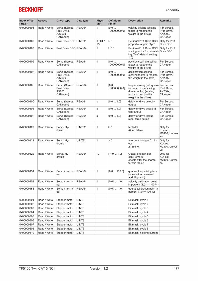
Appendix
TF5100 TwinCAT 3 NC I 477Version: 1.2
Index offset( Hex )
Access Drive- type Data type Phys.unit
Definitionrange
Description Remarks
0x00000105 Read / Write Servo (Sercos,Profi Drive,AX200x,CANopen)
REAL64 1 [0.0 ...100000000.0]
velocity scaling (scalingfactor to react to theweight in the drive)
For Sercos,Profi Drive,AX200x,CANopen
0x00000106 Read / Write Profi Drive DSC UINT32 0.001 *1/s
≥ 0 Profibus/Profi Drive DSC:proportional gain 'Kpc'
Only for ProfiDrive DSC
0x00000107 Read / Write Profi Drive DSC REAL64 1 ≥ 0.0 Profibus/Profi Drive DSC:scaling factor for calculat-ing 'Xerr' (default setting:1.0)
Only for ProfiDrive DSC
0x00000109 Read / Write Servo (Sercos,CANopen)
REAL64 1 [0.0 ...100000000.0]
position scaling (scalingfactor to react to theweight in the drive)
For Sercos,CANopen
0x0000010A Read / Write Servo (Sercos,Profi Drive,AX200x,CANopen)
REAL64 1 [0.0 ...100000000.0]
acceleration scaling(scaling factor to react tothe weight in the drive)
For Sercos,Profi Drive,AX200x,CANopen
0x0000010B Read / Write Servo (Sercos,Profi Drive,AX200x,CANopen)
REAL64 1 [0.0 ...100000000.0]
torque scaling (rotary mo-tor) resp. force scaling(linear motor) (scalingfactor to react to theweight in the drive)
For Sercos,Profi Drive,AX200x,CANopen
0x0000010D Read / Write Servo (Sercos,CANopen)
REAL64 s [0.0 ... 1.0] delay for drive velocityoutput
For Sercos,CANopen
0x0000010E Read / Write Servo (Sercos,CANopen)
REAL64 s [0.0 ... 1.0] delay for drive accelera-tion output
For Sercos,CANopen
0x0000010F Read / Write Servo (Sercos,CANopen)
REAL64 s [0.0 ... 1.0] delay for drive torqueresp. force output
For Sercos,CANopen
0x00000120 Read / Write Servo/ Hy-draulic
UINT32 1 ≥ 0 table-ID(0: no table)
Only forKL4xxx,M2400, Univer-sal
0x00000121 Read / Write Servo/ Hy-draulic
UINT32 1 ≥ 0 Interpolation-type 0: Lin-ear2: Spline
Only forKL4xxx,M2400, Univer-sal
0x00000122 Read / Write Servo/ Hy-draulic
REAL64 % [-1.0 ... 1.0] Output offset in per-centRemark:effects after the charac-teristic table !
Only forKL4xxx,M2400, Univer-sal
0x00000151 Read / Write Servo / non lin-ear
REAL64 1 [0.0 ... 100.0] quadrant equalizing fac-tor (relation between Iand III quadr.)
0x00000152 Read / Write Servo / non lin-ear
REAL64 1 [0.01 ... 1.0] velocity calibration pointin percent (1.0 == 100 %)
0x00000153 Read / Write Servo / non lin-ear
REAL64 1 [0.01 ... 1.0] output calibration point inpercent (1.0 ==100 %)
0x00000301 Read / Write Stepper motor UINT8 Bit mask: cycle 10x00000302 Read / Write Stepper motor UINT8 Bit mask: cycle 20x00000303 Read / Write Stepper motor UINT8 Bit mask: cycle 30x00000304 Read / Write Stepper motor UINT8 Bit mask: cycle 40x00000305 Read / Write Stepper motor UINT8 Bit mask: cycle 50x00000306 Read / Write Stepper motor UINT8 Bit mask: cycle 60x00000307 Read / Write Stepper motor UINT8 Bit mask: cycle 70x00000308 Read / Write Stepper motor UINT8 Bit mask: cycle 80x00000310 Read / Write Stepper motor UINT8 Bit mask: holding current
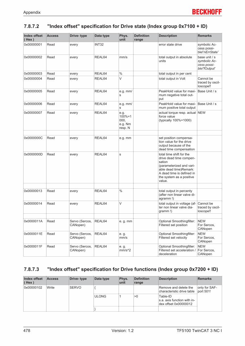
Appendix
TF5100 TwinCAT 3 NC I478 Version: 1.2
7.8.7.2 "Index offset" specification for Drive state (Index group 0x7100 + ID)
Index offset( Hex )
Access Drive- type Data type Phys.unit
Definitionrange
Description Remarks
0x00000001 Read every INT32 error state drive symbolic Ac-cess possi-ble!'nErrState'
0x00000002 Read every REAL64 mm/s total output in absoluteunits
base unit / ssymbolic Ac-cess possi-ble!'fOutput'
0x00000003 Read every REAL64 % total output in per cent0x00000004 Read every REAL64 V total output in Volt Cannot be
traced by oscil-loscope!!
0x00000005 Read every REAL64 e.g. mm/s
PeakHold value for maxi-mum negative total out-put
Base Unit / s
0x00000006 Read every REAL64 e.g. mm/s
PeakHold value for maxi-mum positive total output
Base Unit / s
0x00000007 Read every REAL64 e.g.100%=1000,e.g. Nmresp. N
actual torque resp. actualforce value(typically 100%=1000)
NEW
0x0000000C Read every REAL64 e.g. mm set position compensa-tion value for the driveoutput because of thedead time compensation
0x0000000D Read every REAL64 s total time shift for thedrive dead time compen-sation(parameterized and vari-able dead time)Remark:A dead time is defined inthe system as a positivevalue.
0x00000013 Read every REAL64 % total output in percenty(after non linear valve di-agramm !)
0x00000014 Read every REAL64 V total output in voltage (af-ter non linear valve dia-gramm !)
Cannot betraced by oscil-loscope!!
0x0000011A Read Servo (Sercos,CANopen)
REAL64 e. g. mm Optional Smoothingfilter:Filtered set position
NEWFor Sercos,CANopen
0x0000011E Read Servo (Sercos,CANopen)
REAL64 e. g.mm/s
Optional Smoothingfilter:Filtered set velocity
NEWFor Sercos,CANopen
0x0000011F Read Servo (Sercos,CANopen)
REAL64 e. g.mm/s^2
Optional Smoothingfilter:Filtered set acceleration /deceleration
NEWFor Sercos,CANopen
7.8.7.3 "Index offset" specification for Drive functions (Index group 0x7200 + ID)
Index offset( Hex )
Access Drive- type Data type Phys.unit
Definitionrange
Description Remarks
0x00000102 Write SERVO { Remove and delete thecharacteristic drive table
only for SAF-port 501!
ULONG 1 >0 Table-IDs.a. axis function with in-dex offset 0x00000012
}
Appendix
TF5100 TwinCAT 3 NC I 479Version: 1.2
7.8.7.4 "Index offset" specification for cyclic Drive process data (Index group0x7300 + ID)

Appendix
TF5100 TwinCAT 3 NC I480 Version: 1.2
Index offset( Hex )
Access Drive- type Data type Phys.unit
Definitionrange
Description Remarks
0x00000000 Read / Write every (NC→IO) { STRUCT s.drive-interface
DRIVE-OUTPUT-STRUCTURE (NC→IO,40 Byte)NC-DRIVESTRUCT_OUT2
Write commandonly optional!Consider safetyaspects !
INT32 INC ≥ 0 nOutData1INT32 INC 2^31 nOutData2UINT8 1 ≥ 0 nControl1UINT8 1 ≥ 0 nControl2UINT8 1 ≥ 0 nControl3UINT8 1 ≥ 0 nControl4INT32 INC ≥ 0 nOutData3INT32 INC ≥ 0 nOutData4INT32 INC ≥ 0 nOutData5INT32 INC ≥ 0 nOutData6UINT8 1 ≥ 0 nControl5UINT8 1 ≥ 0 nControl6UINT8 1 ≥ 0 nControl7UINT8 1 ≥ 0 nControl8INT32 1 ≥ 0 reservedINT32 1 ≥ 0 reserved}
0x00000001 Write every (NC→IO) { STRUCT s.Drive-Interface
Bitwise access to DRIVE-OUTPUT-STRUC-TURE(NC→IO, 40 Byte)NC-DRIVESTRUCT_OUT2
Write commandonly optional!Consider safetyaspects
UINT32 1 [0 … 39] ByteOffset
Relative address offset[0..39] in drive outputstructure. E.G.: To write “nCon-trol1” the ByteOffset mustbe 8.
UINT32 1 [0x00000000…0xFFFFFFFF]
BitSelectMask (BSM)
The mask defines writeenabled bits in aDWORD. Zero bits areprotected and remain un-affected.
UINT32 1 [0x00000000…0xFFFFFFFF]
Value
Only those bits in valueare overwritten whereBSM equals 1.
}
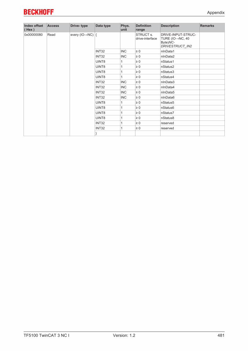
Appendix
TF5100 TwinCAT 3 NC I 481Version: 1.2
Index offset( Hex )
Access Drive- type Data type Phys.unit
Definitionrange
Description Remarks
0x00000080 Read every (IO→NC) { STRUCT s.drive-interface
DRIVE-INPUT-STRUC-TURE (IO→NC, 40Byte)NC-DRIVESTRUCT_IN2
INT32 INC ≥ 0 nInData1INT32 INC ≥ 0 nInData2UINT8 1 ≥ 0 nStatus1UINT8 1 ≥ 0 nStatus2UINT8 1 ≥ 0 nStatus3UINT8 1 ≥ 0 nStatus4INT32 INC ≥ 0 nInData3INT32 INC ≥ 0 nInData4INT32 INC ≥ 0 nInData5INT32 INC ≥ 0 nInData6UINT8 1 ≥ 0 nStatus5UINT8 1 ≥ 0 nStatus6UINT8 1 ≥ 0 nStatus7UINT8 1 ≥ 0 nStatus8INT32 1 ≥ 0 reservedINT32 1 ≥ 0 reserved}
Appendix
TF5100 TwinCAT 3 NC I482 Version: 1.2
7.8.8 Specification Tables
7.8.8.1 "Index offset" specification for Table parameter (Index group 0xA000 + ID)
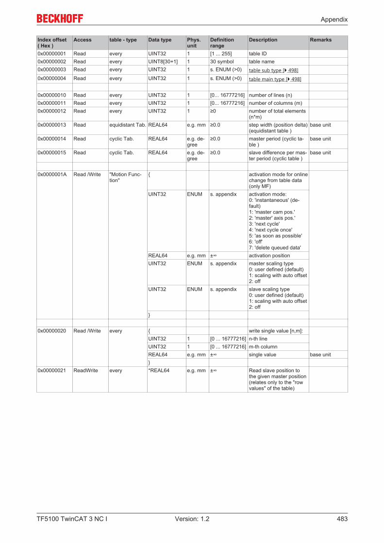
Appendix
TF5100 TwinCAT 3 NC I 483Version: 1.2
Index offset( Hex )
Access table - type Data type Phys.unit
Definitionrange
Description Remarks
0x00000001 Read every UINT32 1 [1 ... 255] table ID0x00000002 Read every UINT8[30+1] 1 30 symbol table name0x00000003 Read every UINT32 1 s. ENUM (>0) table sub type [} 498]0x00000004 Read every UINT32 1 s. ENUM (>0) table main type [} 498]
0x00000010 Read every UINT32 1 [0... 16777216] number of lines (n)0x00000011 Read every UINT32 1 [0... 16777216] number of columns (m)0x00000012 Read every UINT32 1 ≥0 number of total elements
(n*m)0x00000013 Read equidistant Tab. REAL64 e.g. mm ≥0.0 step width (position delta)
(equidistant table )base unit
0x00000014 Read cyclic Tab. REAL64 e.g. de-gree
≥0.0 master period (cyclic ta-ble )
base unit
0x00000015 Read cyclic Tab. REAL64 e.g. de-gree
≥0.0 slave difference per mas-ter period (cyclic table )
base unit
0x0000001A Read /Write "Motion Func-tion"
{ activation mode for onlinechange from table data(only MF)
UINT32 ENUM s. appendix activation mode:0: 'instantaneous' (de-fault) 1: 'master cam pos.' 2: 'master' axis pos.' 3: 'next cycle' 4: 'next cycle once' 5: 'as soon as possible' 6: 'off' 7: 'delete queued data'
REAL64 e.g. mm ±∞ activation positionUINT32 ENUM s. appendix master scaling type
0: user defined (default) 1: scaling with auto offset 2: off
UINT32 ENUM s. appendix slave scaling type 0: user defined (default) 1: scaling with auto offset 2: off
}
0x00000020 Read /Write every { write single value [n,m]:UINT32 1 [0 ... 16777216] n-th lineUINT32 1 [0 ... 16777216] m-th columnREAL64 e.g. mm ±∞ single value base unit}
0x00000021 ReadWrite every *REAL64 e.g. mm ±∞ Read slave position tothe given master position(relates only to the "rowvalues" of the table)

Appendix
TF5100 TwinCAT 3 NC I484 Version: 1.2
Index offset( Hex )
Access table - type Data type Phys.unit
Definitionrange
Description Remarks
0x00000022 ReadWrite "Motion Func-tion"
Write Read the "Motion Func-tion" as fixed values("scatter plot")
only line by linepossible!(multi-ple integer)
{UINT16 1 0/1 Initialisation of data (copy
of actual data) ?UINT16 1 Bitmask (≥0) Select bit mask (number
of columns is one columnfor the masterpositionplus number of bits):Bit 0:Pos (Slave) Bit 1: Velo (Slave) Bit 2: Acc (Slave) Bit 3: Jerk (Slave)
REAL64 z.B. mm ±∞ Startposition (Master)REAL64 z.B. mm > 0.0 Inkrement}Read{REAL64[x*m] z.B. mm ±∞ Generating the values of
x rows beginning with themaster start position:(x*m)-values (one ormore rows)
}0x00000023 ReadWrite every Write Read slave values to
given master position (re-lates only to the "row val-ues" of the table)
REAL64 z.B. mm ±∞ master positionRead{REAL64 z.B. mm ±∞ slave positionREAL64 mm/s ±∞ slave velocityREAL64 mm/s^2 ±∞ slave acceleration}
0x00000050 Read /Write every REAL64 [64] 1 ±∞ Characteristic table val-ues [} 500]
0x00000050 ReadWrite every Write Read the characteristictable values in depen-dency to the nominalmaster velocity
REAL64 [64] ... ±∞ optional nominal mastervelocity "fMaster-VeloNom" (normed =>1.0 mm/s), the other values are notused
ReadREAL64 [64] ... ±∞ Read the characteristic
table values [} 500]
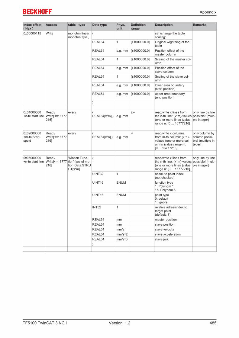
Appendix
TF5100 TwinCAT 3 NC I 485Version: 1.2
Index offset( Hex )
Access table - type Data type Phys.unit
Definitionrange
Description Remarks
0x00000115 Write monoton linear,monoton zykl.,
{ set /change the tablescaling:
REAL64 1 [±1000000.0] Original wightning of thetable
REAL64 e.g. mm [±1000000.0] Position offset of themaster column
REAL64 1 [±1000000.0] Scaling of the master col-umn
REAL64 e.g. mm [±1000000.0] Position offset of theslave column
REAL64 1 [±1000000.0] Scaling of the slave col-umn
REAL64 e.g. mm [±1000000.0] lower area boundary(start position)
REAL64 e.g. mm [±1000000.0] upper area boundary(end position)
}
0x01000000+n-te start line
Read /Write[<=16777216]
every { REAL64[x*m] } e.g. mm
±∞ read/write x lines fromthe n-th line: (x*m)-values(one or more lines )valuerange n: [0 ... 16777216]
only line by linepossible! (multi-ple integer)
0x02000000+m-te Start-spold
Read /Write[<=16777216]
every { REAL64[x*n] } e.g. mm
∞ read/write x columnsfrom m-th column: (x*n)-values (one or more col-umns )value range m:[0 ... 16777216]
only column bycolumn possi-ble! (multiple in-teger)
0x05000000+n-te start line
Read /Write[<=16777216]
"Motion Func-tion"(law of mo-tion)Data:STRUCT[x*m]
{ read/write x lines fromthe n-th line: (x*m)-values(one or more lines )valuerange n: [0 ... 16777216]
only line by linepossible! (multi-ple integer)
UINT32 1 absolute point index (not checked)
UINT16 ENUM function type 1: Polynom 1 15: Polynom 5
UINT16 ENUM point type 0: default 1: ignore
INT32 1 relative adressindex totarget point (default: 1)
REAL64 mm master positionREAL64 mm slave positionREAL64 mm/s slave velocityREAL64 mm/s^2 slave accelerationREAL64 mm/s^3 slave jerk}
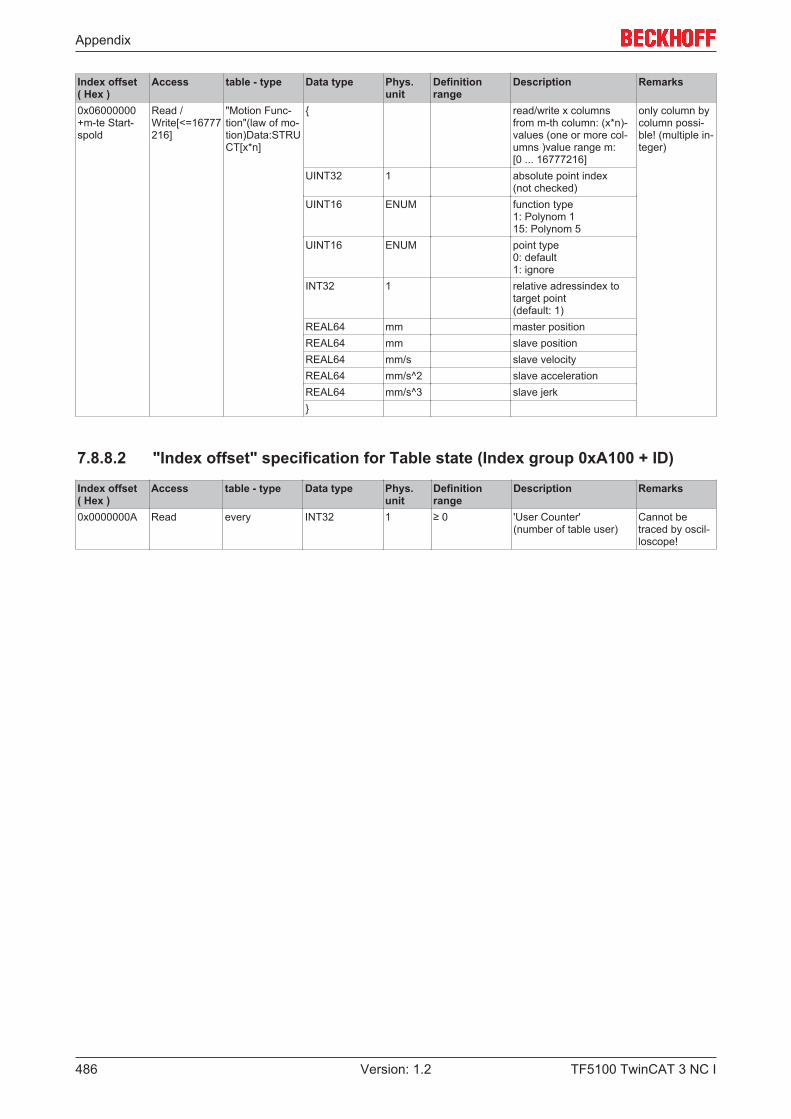
Appendix
TF5100 TwinCAT 3 NC I486 Version: 1.2
Index offset( Hex )
Access table - type Data type Phys.unit
Definitionrange
Description Remarks
0x06000000+m-te Start-spold
Read /Write[<=16777216]
"Motion Func-tion"(law of mo-tion)Data:STRUCT[x*n]
{ read/write x columnsfrom m-th column: (x*n)-values (one or more col-umns )value range m:[0 ... 16777216]
only column bycolumn possi-ble! (multiple in-teger)
UINT32 1 absolute point index (not checked)
UINT16 ENUM function type 1: Polynom 1 15: Polynom 5
UINT16 ENUM point type 0: default 1: ignore
INT32 1 relative adressindex totarget point (default: 1)
REAL64 mm master positionREAL64 mm slave positionREAL64 mm/s slave velocityREAL64 mm/s^2 slave accelerationREAL64 mm/s^3 slave jerk}
7.8.8.2 "Index offset" specification for Table state (Index group 0xA100 + ID)
Index offset( Hex )
Access table - type Data type Phys.unit
Definitionrange
Description Remarks
0x0000000A Read every INT32 1 ≥ 0 'User Counter'(number of table user)
Cannot betraced by oscil-loscope!
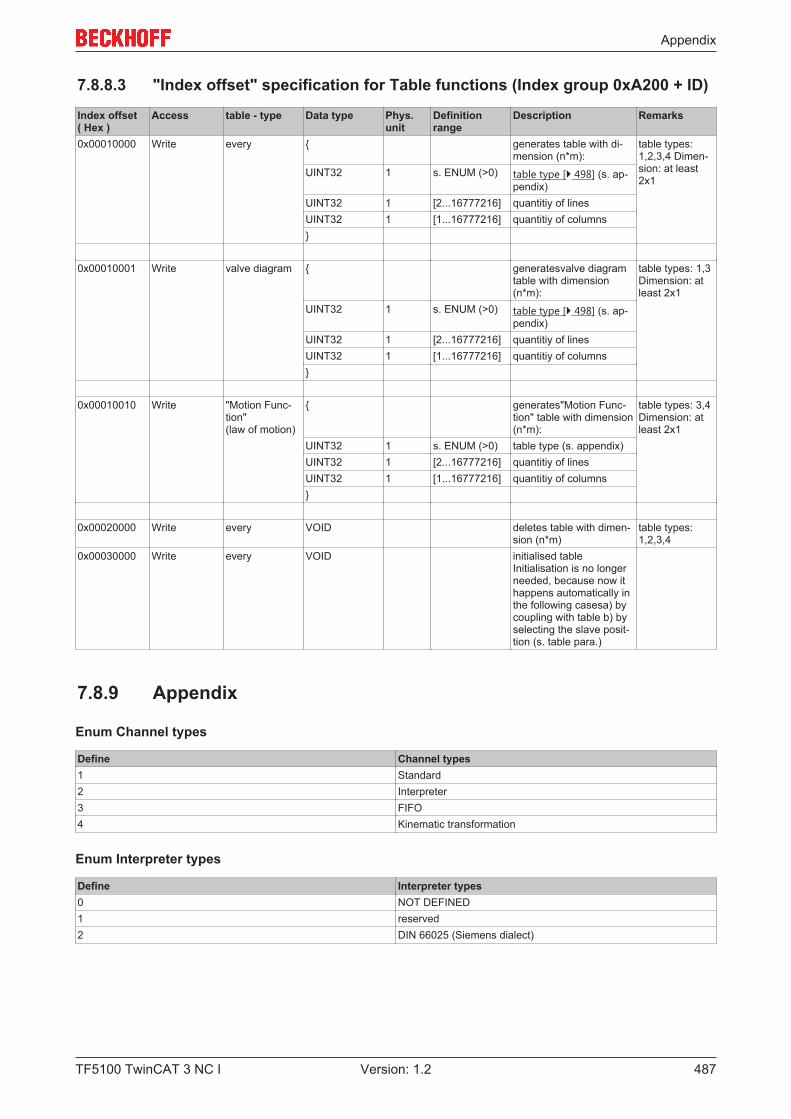
Appendix
TF5100 TwinCAT 3 NC I 487Version: 1.2
7.8.8.3 "Index offset" specification for Table functions (Index group 0xA200 + ID)
Index offset( Hex )
Access table - type Data type Phys.unit
Definitionrange
Description Remarks
0x00010000 Write every { generates table with di-mension (n*m):
table types:1,2,3,4 Dimen-sion: at least2x1
UINT32 1 s. ENUM (>0) table type [} 498] (s. ap-pendix)
UINT32 1 [2...16777216] quantitiy of linesUINT32 1 [1...16777216] quantitiy of columns}
0x00010001 Write valve diagram { generatesvalve diagramtable with dimension(n*m):
table types: 1,3Dimension: atleast 2x1
UINT32 1 s. ENUM (>0) table type [} 498] (s. ap-pendix)
UINT32 1 [2...16777216] quantitiy of linesUINT32 1 [1...16777216] quantitiy of columns}
0x00010010 Write "Motion Func-tion"(law of motion)
{ generates"Motion Func-tion" table with dimension(n*m):
table types: 3,4Dimension: atleast 2x1
UINT32 1 s. ENUM (>0) table type (s. appendix)UINT32 1 [2...16777216] quantitiy of linesUINT32 1 [1...16777216] quantitiy of columns}
0x00020000 Write every VOID deletes table with dimen-sion (n*m)
table types:1,2,3,4
0x00030000 Write every VOID initialised tableInitialisation is no longerneeded, because now ithappens automatically inthe following casesa) bycoupling with table b) byselecting the slave posit-tion (s. table para.)
7.8.9 Appendix
Enum Channel types
Define Channel types1 Standard2 Interpreter3 FIFO4 Kinematic transformation
Enum Interpreter types
Define Interpreter types0 NOT DEFINED1 reserved2 DIN 66025 (Siemens dialect)
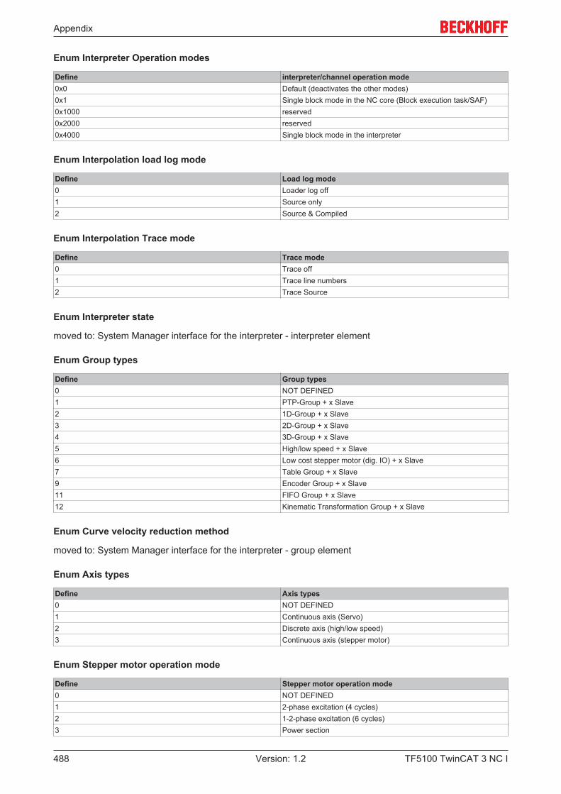
Appendix
TF5100 TwinCAT 3 NC I488 Version: 1.2
Enum Interpreter Operation modes
Define interpreter/channel operation mode0x0 Default (deactivates the other modes)0x1 Single block mode in the NC core (Block execution task/SAF)0x1000 reserved0x2000 reserved0x4000 Single block mode in the interpreter
Enum Interpolation load log mode
Define Load log mode0 Loader log off1 Source only2 Source & Compiled
Enum Interpolation Trace mode
Define Trace mode0 Trace off1 Trace line numbers2 Trace Source
Enum Interpreter state
moved to: System Manager interface for the interpreter - interpreter element
Enum Group types
Define Group types0 NOT DEFINED1 PTP-Group + x Slave2 1D-Group + x Slave3 2D-Group + x Slave4 3D-Group + x Slave5 High/low speed + x Slave6 Low cost stepper motor (dig. IO) + x Slave7 Table Group + x Slave9 Encoder Group + x Slave11 FIFO Group + x Slave12 Kinematic Transformation Group + x Slave
Enum Curve velocity reduction method
moved to: System Manager interface for the interpreter - group element
Enum Axis types
Define Axis types0 NOT DEFINED1 Continuous axis (Servo)2 Discrete axis (high/low speed)3 Continuous axis (stepper motor)
Enum Stepper motor operation mode
Define Stepper motor operation mode0 NOT DEFINED1 2-phase excitation (4 cycles)2 1-2-phase excitation (6 cycles)3 Power section
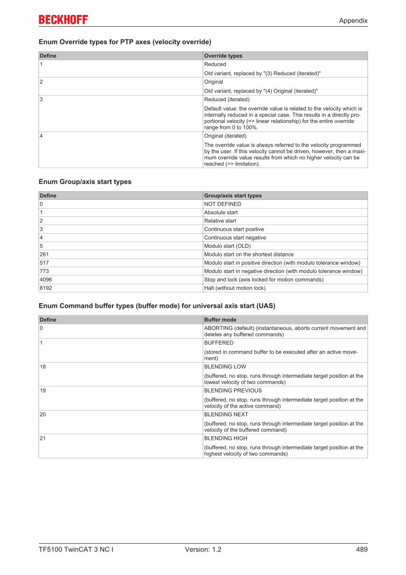
Appendix
TF5100 TwinCAT 3 NC I 489Version: 1.2
Enum Override types for PTP axes (velocity override)
Define Override types1 Reduced
Old variant, replaced by "(3) Reduced (iterated)"2 Original
Old variant, replaced by "(4) Original (iterated)"3 Reduced (iterated)
Default value: the override value is related to the velocity which isinternally reduced in a special case. This results in a directly pro-portional velocity (=> linear relationship) for the entire overriderange from 0 to 100%.
4 Original (iterated)
The override value is always referred to the velocity programmedby the user. If this velocity cannot be driven, however, then a maxi-mum override value results from which no higher velocity can bereached (=> limitation).
Enum Group/axis start types
Define Group/axis start types0 NOT DEFINED1 Absolute start2 Relative start3 Continuous start positive4 Continuous start negative5 Modulo start (OLD)261 Modulo start on the shortest distance517 Modulo start in positive direction (with modulo tolerance window)773 Modulo start in negative direction (with modulo tolerance window)4096 Stop and lock (axis locked for motion commands)8192 Halt (without motion lock)
Enum Command buffer types (buffer mode) for universal axis start (UAS)
Define Buffer mode0 ABORTING (default) (instantaneous, aborts current movement and
deletes any buffered commands)1 BUFFERED
(stored in command buffer to be executed after an active move-ment)
18 BLENDING LOW
(buffered, no stop, runs through intermediate target position at thelowest velocity of two commands)
19 BLENDING PREVIOUS
(buffered, no stop, runs through intermediate target position at thevelocity of the active command)
20 BLENDING NEXT
(buffered, no stop, runs through intermediate target position at thevelocity of the buffered command)
21 BLENDING HIGH
(buffered, no stop, runs through intermediate target position at thehighest velocity of two commands)
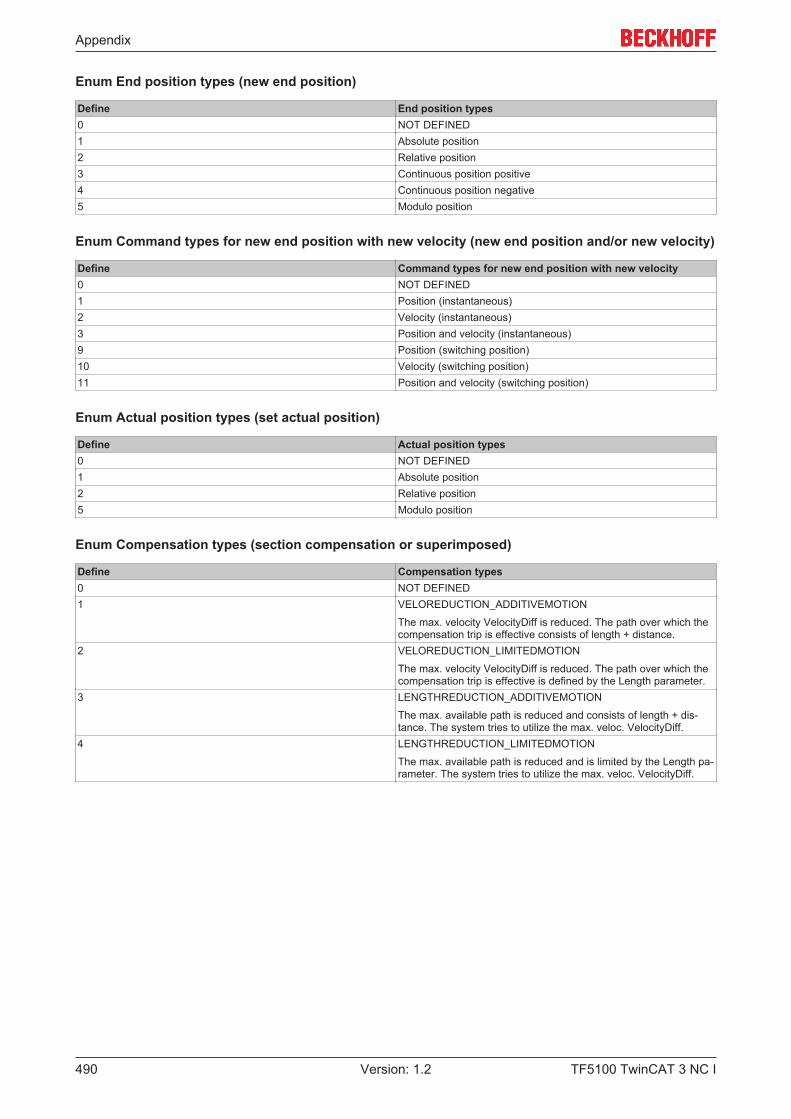
Appendix
TF5100 TwinCAT 3 NC I490 Version: 1.2
Enum End position types (new end position)
Define End position types0 NOT DEFINED1 Absolute position2 Relative position3 Continuous position positive4 Continuous position negative5 Modulo position
Enum Command types for new end position with new velocity (new end position and/or new velocity)
Define Command types for new end position with new velocity0 NOT DEFINED1 Position (instantaneous)2 Velocity (instantaneous)3 Position and velocity (instantaneous)9 Position (switching position)10 Velocity (switching position)11 Position and velocity (switching position)
Enum Actual position types (set actual position)
Define Actual position types0 NOT DEFINED1 Absolute position2 Relative position5 Modulo position
Enum Compensation types (section compensation or superimposed)
Define Compensation types0 NOT DEFINED1 VELOREDUCTION_ADDITIVEMOTION
The max. velocity VelocityDiff is reduced. The path over which thecompensation trip is effective consists of length + distance.
2 VELOREDUCTION_LIMITEDMOTION
The max. velocity VelocityDiff is reduced. The path over which thecompensation trip is effective is defined by the Length parameter.
3 LENGTHREDUCTION_ADDITIVEMOTION
The max. available path is reduced and consists of length + dis-tance. The system tries to utilize the max. veloc. VelocityDiff.
4 LENGTHREDUCTION_LIMITEDMOTION
The max. available path is reduced and is limited by the Length pa-rameter. The system tries to utilize the max. veloc. VelocityDiff.
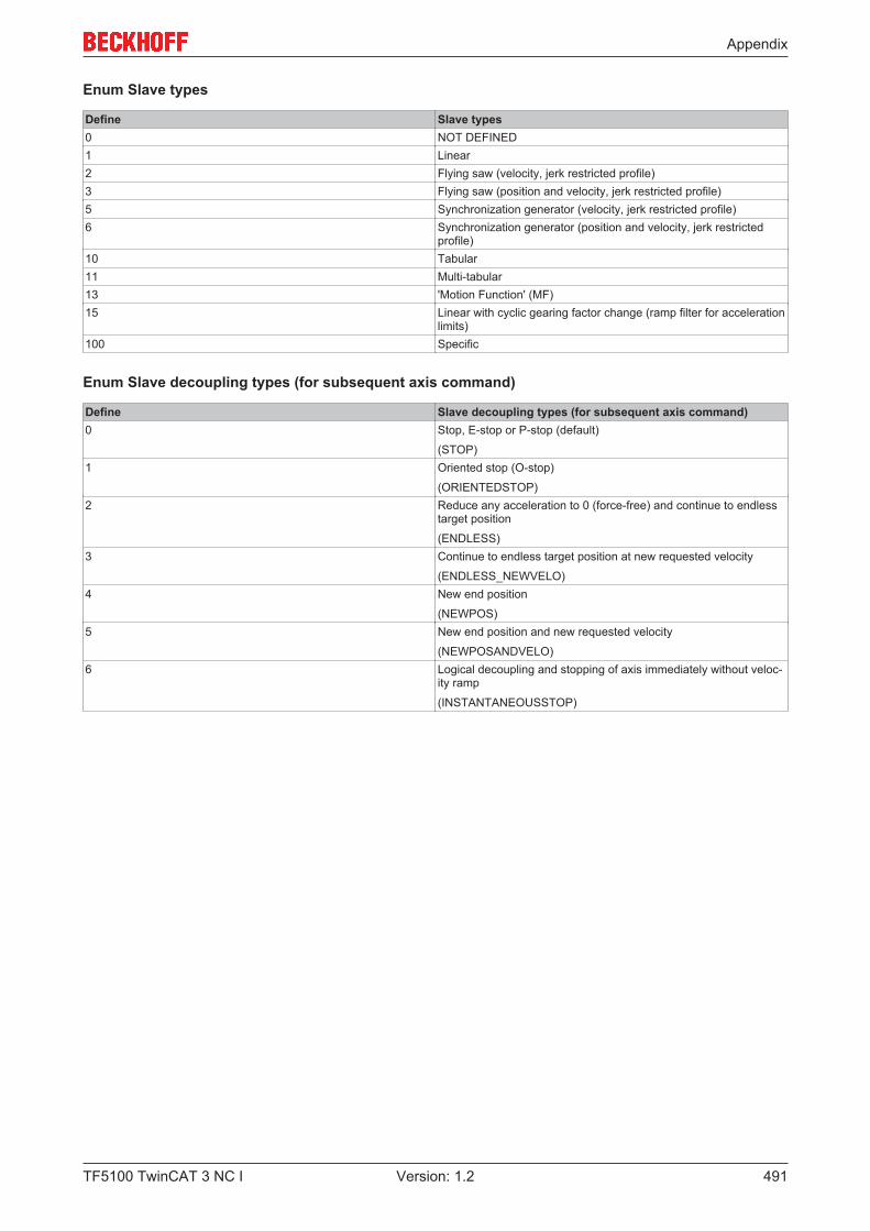
Appendix
TF5100 TwinCAT 3 NC I 491Version: 1.2
Enum Slave types
Define Slave types0 NOT DEFINED1 Linear2 Flying saw (velocity, jerk restricted profile)3 Flying saw (position and velocity, jerk restricted profile)5 Synchronization generator (velocity, jerk restricted profile)6 Synchronization generator (position and velocity, jerk restricted
profile)10 Tabular11 Multi-tabular13 'Motion Function' (MF)15 Linear with cyclic gearing factor change (ramp filter for acceleration
limits)100 Specific
Enum Slave decoupling types (for subsequent axis command)
Define Slave decoupling types (for subsequent axis command)0 Stop, E-stop or P-stop (default)
(STOP)1 Oriented stop (O-stop)
(ORIENTEDSTOP)2 Reduce any acceleration to 0 (force-free) and continue to endless
target position
(ENDLESS)3 Continue to endless target position at new requested velocity
(ENDLESS_NEWVELO)4 New end position
(NEWPOS)5 New end position and new requested velocity
(NEWPOSANDVELO)6 Logical decoupling and stopping of axis immediately without veloc-
ity ramp
(INSTANTANEOUSSTOP)
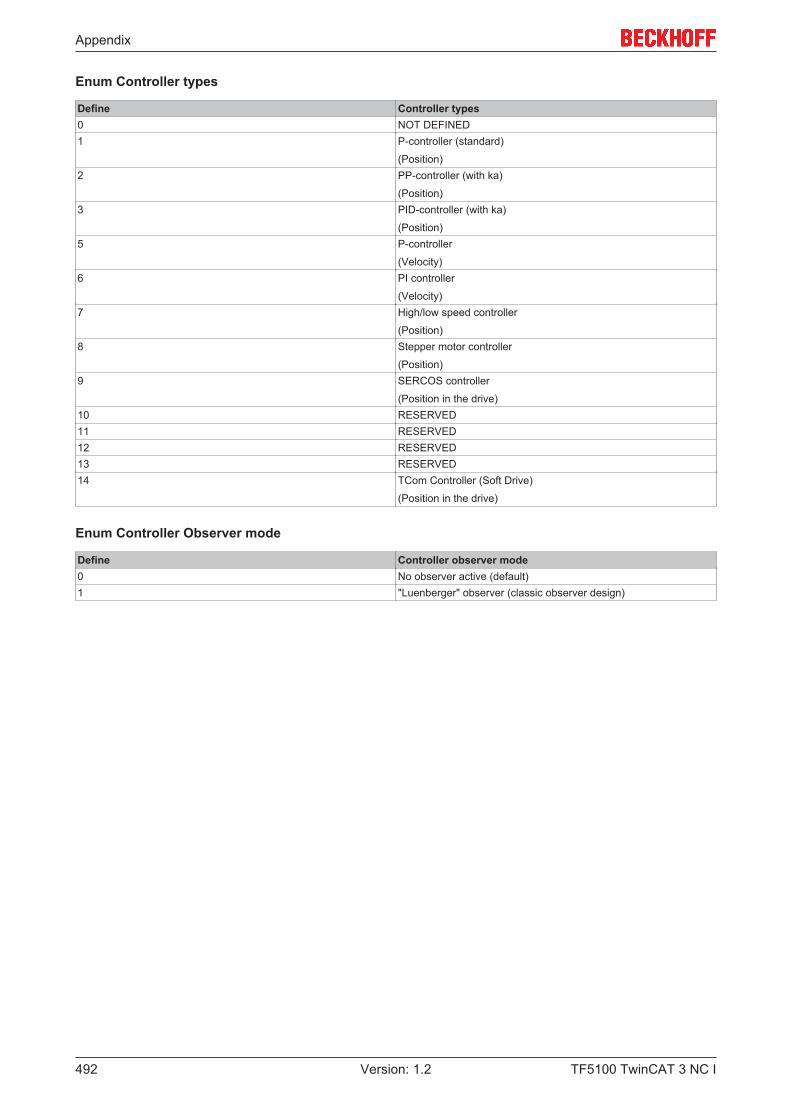
Appendix
TF5100 TwinCAT 3 NC I492 Version: 1.2
Enum Controller types
Define Controller types0 NOT DEFINED1 P-controller (standard)
(Position)2 PP-controller (with ka)
(Position)3 PID-controller (with ka)
(Position)5 P-controller
(Velocity)6 PI controller
(Velocity)7 High/low speed controller
(Position)8 Stepper motor controller
(Position)9 SERCOS controller
(Position in the drive)10 RESERVED11 RESERVED12 RESERVED13 RESERVED14 TCom Controller (Soft Drive)
(Position in the drive)
Enum Controller Observer mode
Define Controller observer mode0 No observer active (default)1 "Luenberger" observer (classic observer design)
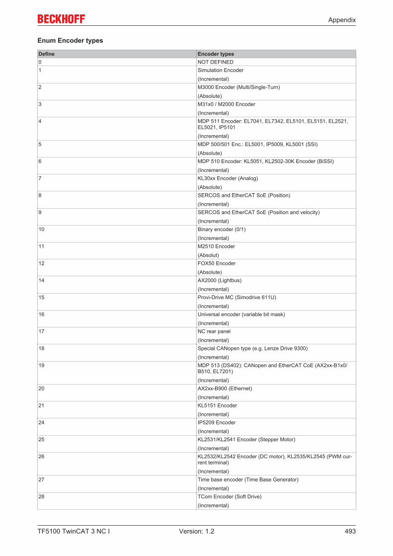
Appendix
TF5100 TwinCAT 3 NC I 493Version: 1.2
Enum Encoder types
Define Encoder types0 NOT DEFINED1 Simulation Encoder
(Incremental)2 M3000 Encoder (Multi/Single-Turn)
(Absolute)3 M31x0 / M2000 Encoder
(Incremental)4 MDP 511 Encoder: EL7041, EL7342, EL5101, EL5151, EL2521,
EL5021, IP5101
(Incremental)5 MDP 500/501 Enc.: EL5001, IP5009, KL5001 (SSI)
(Absolute)6 MDP 510 Encoder: KL5051, KL2502-30K Encoder (BiSSI)
(Incremental)7 KL30xx Encoder (Analog)
(Absolute)8 SERCOS and EtherCAT SoE (Position)
(Incremental)9 SERCOS and EtherCAT SoE (Position and velocity)
(Incremental)10 Binary encoder (0/1)
(Incremental)11 M2510 Encoder
(Absolut)12 FOX50 Encoder
(Absolute)14 AX2000 (Lightbus)
(Incremental)15 Provi-Drive MC (Simodrive 611U)
(Incremental)16 Universal encoder (variable bit mask)
(Incremental)17 NC rear panel
(Incremental)18 Special CANopen type (e.g. Lenze Drive 9300)
(Incremental)19 MDP 513 (DS402): CANopen and EtherCAT CoE (AX2xx-B1x0/
B510, EL7201)
(Incremental)20 AX2xx-B900 (Ethernet)
(Incremental)21 KL5151 Encoder
(Incremental)24 IP5209 Encoder
(Incremental)25 KL2531/KL2541 Encoder (Stepper Motor)
(Incremental)26 KL2532/KL2542 Encoder (DC motor), KL2535/KL2545 (PWM cur-
rent terminal)
(Incremental)27 Time base encoder (Time Base Generator)
(Incremental)28 TCom Encoder (Soft Drive)
(Incremental)
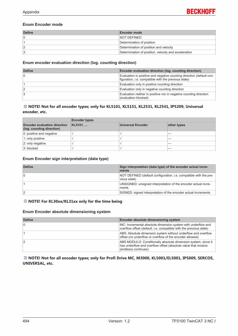
Appendix
TF5100 TwinCAT 3 NC I494 Version: 1.2
Enum Encoder mode
Define Encoder mode0 NOT DEFINED1 Determination of position2 Determination of position and velocity3 Determination of position, velocity and acceleration
Enum encoder evaluation direction (log. counting direction)
Define Encoder evaluation direction (log. counting direction)0 Evaluation in positive and negative counting direction (default con-
figuration, i.e. compatible with the previous state)1 Evaluation only in positive counting direction2 Evaluation only in negative counting direction3 Evaluation neither in positive nor in negative counting direction
(evaluation blocked)
NOTE! Not for all encoder types; only for KL5101, KL5151, KL2531, KL2541, IP5209, Universalencoder, etc.
Encoder typesEncoder evaluation direction (log. counting direction)
KL5101, ... Universal Encoder other types
0: positive and negative √ √ —1: only positive √ √ —2: only negative √ √ —3: blocked √ √ —
Enum Encoder sign interpretation (data type)
Define Sign interpretation (data type) of the encoder actual incre-ments
0 NOT DEFINED (default configuration, i.e. compatible with the pre-vious state)
1 UNSIGNED: unsigned interpretation of the encoder actual incre-ments
2 SIGNED: signed interpretation of the encoder actual increments
NOTE! For KL30xx/KL31xx only for the time being
Enum Encoder absolute dimensioning system
Define Encoder absolute dimensioning system0 INC: Incremental absolute dimension system with underflow and
overflow offset (default, i.e. compatible with the previous state)1 ABS: Absolute dimension system without underflow and overflow
offset (no underflow or overflow of the encoder allowed)2 ABS MODULO: Conditionally absolute dimension system, since it
has underflow and overflow offset (absolute value that modulo(endless) continues)
NOTE! Not for all encoder types; only for Profi Drive MC, M3000, KL5001/EL5001, IP5009, SERCOS,UNIVERSAL, etc.
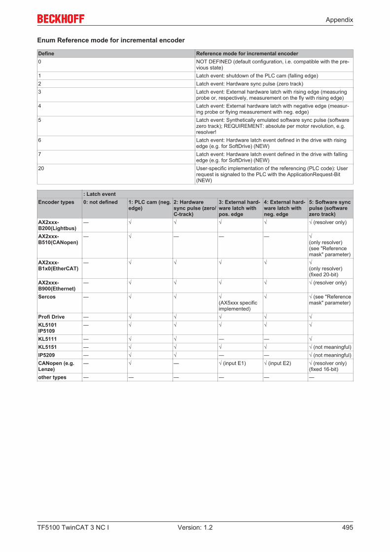
Appendix
TF5100 TwinCAT 3 NC I 495Version: 1.2
Enum Reference mode for incremental encoder
Define Reference mode for incremental encoder0 NOT DEFINED (default configuration, i.e. compatible with the pre-
vious state)1 Latch event: shutdown of the PLC cam (falling edge)2 Latch event: Hardware sync pulse (zero track)3 Latch event: External hardware latch with rising edge (measuring
probe or, respectively, measurement on the fly with rising edge)4 Latch event: External hardware latch with negative edge (measur-
ing probe or flying measurement with neg. edge)5 Latch event: Synthetically emulated software sync pulse (software
zero track); REQUIREMENT: absolute per motor revolution, e.g.resolver!
6 Latch event: Hardware latch event defined in the drive with risingedge (e.g. for SoftDrive) (NEW)
7 Latch event: Hardware latch event defined in the drive with fallingedge (e.g. for SoftDrive) (NEW)
20 User-specific implementation of the referencing (PLC code): Userrequest is signaled to the PLC with the ApplicationRequest-Bit(NEW)
: Latch eventEncoder types 0: not defined 1: PLC cam (neg.
edge)2: Hardwaresync pulse (zero/C-track)
3: External hard-ware latch withpos. edge
4: External hard-ware latch withneg. edge
5: Software syncpulse (softwarezero track)
AX2xxx-B200(Lightbus)
— √ √ √ √ √ (resolver only)
AX2xxx-B510(CANopen)
— √ — — — √(only resolver)(see "Referencemask" parameter)
AX2xxx-B1x0(EtherCAT)
— √ √ √ √ √(only resolver)(fixed 20-bit)
AX2xxx-B900(Ethernet)
— √ √ √ √ √ (resolver only)
Sercos — √ √ √(AX5xxx specificimplemented)
√ √ (see "Referencemask" parameter)
Profi Drive — √ √ √ √ √KL5101IP5109
— √ √ √ √ √
KL5111 — √ √ — — √KL5151 — √ √ √ √ √ (not meaningful)IP5209 — √ √ — — √ (not meaningful)CANopen (e.g.Lenze)
— √ — √ (input E1) √ (input E2) √ (resolver only)(fixed 16-bit)
other types — — — — — —
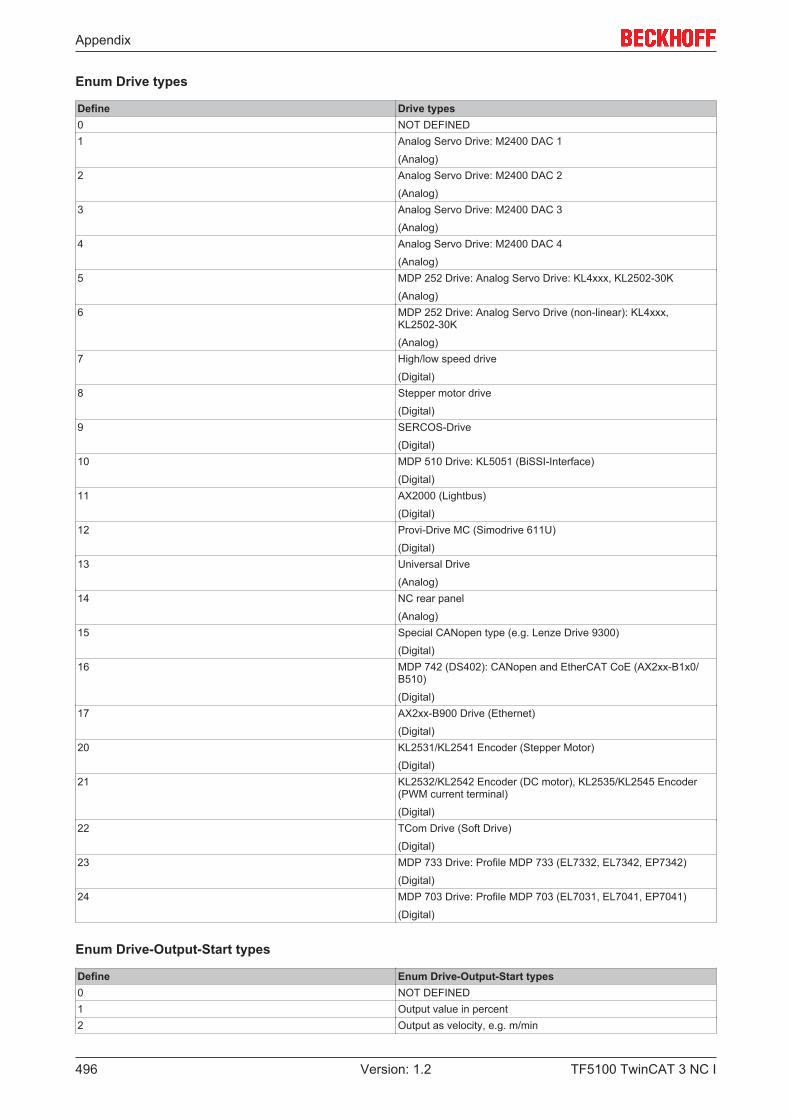
Appendix
TF5100 TwinCAT 3 NC I496 Version: 1.2
Enum Drive types
Define Drive types0 NOT DEFINED1 Analog Servo Drive: M2400 DAC 1
(Analog)2 Analog Servo Drive: M2400 DAC 2
(Analog)3 Analog Servo Drive: M2400 DAC 3
(Analog)4 Analog Servo Drive: M2400 DAC 4
(Analog)5 MDP 252 Drive: Analog Servo Drive: KL4xxx, KL2502-30K
(Analog)6 MDP 252 Drive: Analog Servo Drive (non-linear): KL4xxx,
KL2502-30K
(Analog)7 High/low speed drive
(Digital)8 Stepper motor drive
(Digital)9 SERCOS-Drive
(Digital)10 MDP 510 Drive: KL5051 (BiSSI-Interface)
(Digital)11 AX2000 (Lightbus)
(Digital)12 Provi-Drive MC (Simodrive 611U)
(Digital)13 Universal Drive
(Analog)14 NC rear panel
(Analog)15 Special CANopen type (e.g. Lenze Drive 9300)
(Digital)16 MDP 742 (DS402): CANopen and EtherCAT CoE (AX2xx-B1x0/
B510)
(Digital)17 AX2xx-B900 Drive (Ethernet)
(Digital)20 KL2531/KL2541 Encoder (Stepper Motor)
(Digital)21 KL2532/KL2542 Encoder (DC motor), KL2535/KL2545 Encoder
(PWM current terminal)
(Digital)22 TCom Drive (Soft Drive)
(Digital)23 MDP 733 Drive: Profile MDP 733 (EL7332, EL7342, EP7342)
(Digital)24 MDP 703 Drive: Profile MDP 703 (EL7031, EL7041, EP7041)
(Digital)
Enum Drive-Output-Start types
Define Enum Drive-Output-Start types0 NOT DEFINED1 Output value in percent2 Output as velocity, e.g. m/min
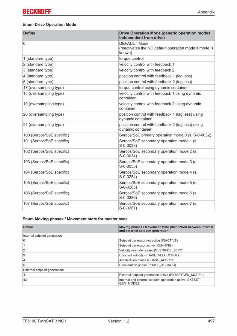
Appendix
TF5100 TwinCAT 3 NC I 497Version: 1.2
Enum Drive Operation Mode
Define Drive Operation Mode (generic operation modesindependent from drive)
0 DEFAULT Mode (reactivates the NC default operation mode if mode isknown)
1 (standard type) torque control2 (standard type) velocity control with feedback 13 (standard type) velocity control with feedback 24 (standard type) position control with feedback 1 (lag less)5 (standard type) position control with feedback 2 (lag less)17 (oversampling type) torque control using dynamic container18 (oversampling type) velocity control with feedback 1 using dynamic
container19 (oversampling type) velocity control with feedback 2 using dynamic
container20 (oversampling type) position control with feedback 1 (lag less) using
dynamic container21 (oversampling type) position control with feedback 2 (lag less) using
dynamic container100 (Sercos/SoE specific) Sercos/SoE primary operation mode 0 (s. S-0-0032)101 (Sercos/SoE specific) Sercos/SoE secondary operation mode 1 (s.
S-0-0033)102 (Sercos/SoE specific) Sercos/SoE secondary operation mode 2 (s.
S-0-0034)103 (Sercos/SoE specific) Sercos/SoE secondary operation mode 3 (s.
S-0-0035)104 (Sercos/SoE specific) Sercos/SoE secondary operation mode 4 (s.
S-0-0284)105 (Sercos/SoE specific) Sercos/SoE secondary operation mode 5 (s.
S-0-0285)106 (Sercos/SoE specific) Sercos/SoE secondary operation mode 6 (s.
S-0-0286)107 (Sercos/SoE specific) Sercos/SoE secondary operation mode 7 (s.
S-0-0287)
Enum Moving phases / Movement state for master axes
Define Moving phases / Movement state (distinction between internaland external setpoint generation)
Internal setpoint generation0 Setpoint generator not active (INACTIVE)1 Setpoint generator active (RUNNING)2 Velocity override is zero (OVERRIDE_ZERO)3 Constant velocity (PHASE_VELOCONST)4 Acceleration phase (PHASE_ACCPOS)5 Deceleration phase (PHASE_ACCNEG)External setpoint generation:41 External setpoint generation active (EXTSETGEN_MODE1)42 Internal and external setpoint generation active (EXTSET-
GEN_MODE2)
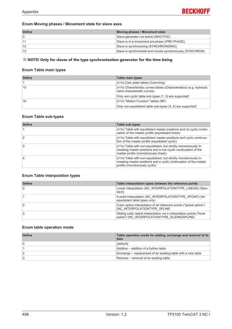
Appendix
TF5100 TwinCAT 3 NC I498 Version: 1.2
Enum Moving phases / Movement state for slave axes
Define Moving phases / Movement state0 Slave generator not active (INACTIVE)11 Slave is in a movement pre-phase (PRE-PHASE)12 Slave is synchronizing (SYNCHRONIZING)13 Slave is synchronized and moves synchronously (SYNCHRON)
NOTE! Only for slaves of the type synchronization generator for the time being
Enum Table main types
Define Table main types1 (n*m) Cam plate tables (Camming)10 (n*m) Characteristic curves tables (Characteristics) (e.g. hydraulic
valve characteristic curves)
Only non-cyclic table sub-types (1, 3) are supported!16 (n*m) "Motion Function" tables (MF)
Only non-equidistant table sub-types (3, 4) are supported!
Enum Table sub-types
Define Table sub types1 (n*m) Table with equidistant master positions and no cyclic contin-
uation of the master profile (equidistant linear)2 (n*m) Table with equidistant master positions and cyclic continua-
tion of the master profile (equidistant cyclic)3 (n*m) Table with non-equidistant, but strictly monotonously in-
creasing master positions and a non-cyclic continuation of themaster profile (monotonously linear)
4 (n*m) Table with non-equidistant, but strictly monotonously in-creasing master positions and a cyclic continuation of the masterprofile (monotonously cyclic)
Enum Table interpolation types
Define Table interpolation types between the reference points0 Linear interpolation (NC_INTERPOLATIONTYPE_LINEAR) (Stan-
dard)1 4-point interpolation (NC_INTERPOLATIONTYPE_4POINT) (for
equidistant table types only)2 Cubic spline interpolation of all reference points ("global spline")
(NC_INTERPOLATIONTYPE_SPLINE3 Sliding cubic spline interpolation via n interpolation points ("local
spline") (NC_INTERPOLATIONTYPE_SLIDINGSPLINE)
Enum table operation mode
Define Table operation mode for adding, exchange and removal of ta-bles
0 (default)1 Additive – addition of a further table2 Exchange – replacement of an existing table with a new table3 Remove – removal of an existing table
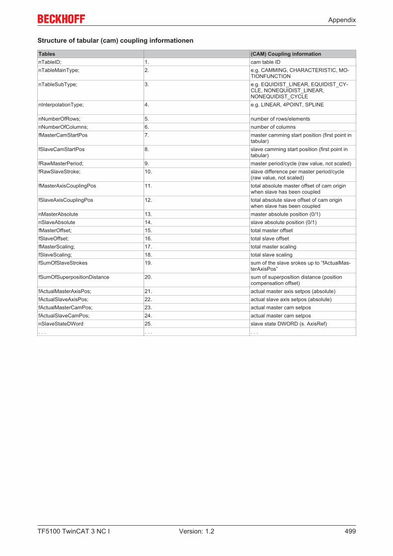
Appendix
TF5100 TwinCAT 3 NC I 499Version: 1.2
Structure of tabular (cam) coupling informationen
Tables (CAM) Coupling informationnTableID; 1. cam table IDnTableMainType; 2. e.g. CAMMING, CHARACTERISTIC, MO-
TIONFUNCTIONnTableSubType; 3. e.g. EQUIDIST_LINEAR, EQUIDIST_CY-
CLE, NONEQUIDIST_LINEAR,NONEQUIDIST_CYCLE
nInterpolationType; 4. e.g. LINEAR, 4POINT, SPLINE
nNumberOfRows; 5. number of rows/elementsnNumberOfColumns; 6. number of columnsfMasterCamStartPos 7. master camming start position (first point in
tabular)fSlaveCamStartPos 8. slave camming start position (first point in
tabular)fRawMasterPeriod; 9. master period/cycle (raw value, not scaled)fRawSlaveStroke; 10. slave difference per master period/cycle
(raw value, not scaled)fMasterAxisCouplingPos 11. total absolute master offset of cam origin
when slave has been coupledfSlaveAxisCouplingPos 12. total absolute slave offset of cam origin
when slave has been couplednMasterAbsolute 13. master absolute position (0/1)nSlaveAbsolute 14. slave absolute position (0/1)fMasterOffset; 15. total master offsetfSlaveOffset; 16. total slave offsetfMasterScaling; 17. total master scalingfSlaveScaling; 18. total slave scalingfSumOfSlaveStrokes 19. sum of the slave srokes up to “fActualMas-
terAxisPos”fSumOfSuperpositionDistance 20. sum of superposition distance (position
compensation offset)fActualMasterAxisPos; 21. actual master axis setpos (absolute)fActualSlaveAxisPos; 22. actual slave axis setpos (absolute)fActualMasterCamPos; 23. actual master cam setposfActualSlaveCamPos; 24. actual master cam setposnSlaveStateDWord 25. slave state DWORD (s. AxisRef). . . . . . . . .
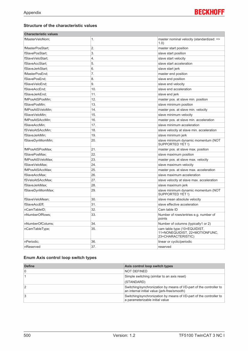
Appendix
TF5100 TwinCAT 3 NC I500 Version: 1.2
Structure of the characteristic values
Characteristic valuesfMasterVeloNom; 1. master nominal velocity (standardized: =>
1.0)fMasterPosStart; 2. master start positionfSlavePosStart; 3. slave start positionfSlaveVeloStart; 4. slave start velocityfSlaveAccStart; 5. slave start accelerationfSlaveJerkStart; 6. slave start jerkfMasterPosEnd; 7. master end positionfSlavePosEnd; 8. slave end positionfSlaveVeloEnd; 9. slave end velocityfSlaveAccEnd; 10. slave end accelerationfSlaveJerkEnd; 11. slave end jerkfMPosAtSPosMin; 12. master pos. at slave min. positionfSlavePosMin; 13. slave minimum positionfMPosAtSVeloMin; 14. master pos. at slave min. velocityfSlaveVeloMin; 15. slave minimum velocityfMPosAtSAccMin; 16. master pos. at slave min. accelerationfSlaveAccMin; 17. slave minimum accelerationfSVeloAtSAccMin; 18. slave velocity at slave min. accelerationfSlaveJerkMin; 19. slave minimum jerkfSlaveDynMomMin; 20. slave minimum dynamic momentum (NOT
SUPPORTED YET !)fMPosAtSPosMax; 21. master pos. at slave max. positionfSlavePosMax; 22. slave maximum positionfMPosAtSVeloMax; 23. master pos. at slave max. velocityfSlaveVeloMax; 24. slave maximum velocityfMPosAtSAccMax; 25. master pos. at slave max. accelerationfSlaveAccMax; 26. slave maximum accelerationfSVeloAtSAccMax; 27. slave velocity at slave max. accelerationfSlaveJerkMax; 28. slave maximum jerkfSlaveDynMomMax; 29. slave minimum dynamic momentum (NOT
SUPPORTED YET !)fSlaveVeloMean; 30. slave mean absolute velocityfSlaveAccEff; 31. slave effective accelerationnCamTableID; 32. Cam table IDnNumberOfRows; 33. Number of rows/entries e.g. number of
pointsnNumberOfColums; 34. Number of columns (typically1 or 2)nCamTableType; 35. cam table type (10=EQUIDIST,
11=NONEQUIDIST, 22=MOTIONFUNC,23=CHARACTERISTIC)
nPeriodic; 36. linear or cyclic/periodicnReserved 37. reserved
Enum Axis control loop switch types
Define Axis control loop switch types0 NOT DEFINED1 Simple switching (similar to an axis reset)
(STANDARD)2 Switching/synchronization by means of I/D-part of the controller to
an internal initial value (jerk-free/smooth)3 Switching/synchronization by means of I/D-part of the controller to
a parameterizable initial value