Embed Size (px)
Citation preview

USER MANUAL
GEBRUIKSAANWIJZING GEBRAUCHSANWEISUNG
PALLAS-TG 12/50 SKYLLA-TG 24/30 SKYLLA-TG 24/50
SKYLLA- TG 24/50 3- Phase SKYLLA-TG 24/30 110V
TITAN 48/25
Victron Energy

Manual Titan 1
SECTIONS Page
English 3
Nederlands 32
Deutsch 58
2 Manual Titan
Copyrights 2003 Victron Energy B.V.
All Rights Reserved This publication or parts thereof, may not be reproduced in any form, by any method, for any
purpose.
VICTRON ENERGY B.V. MAKES NO WARRANTY, EITHER EXPESSED OR IMPLIED, INCLUDING BUT NOT LIMITED TO ANY IMPLIED WARRANTIES OF MERCHANTABILITY OR FITNESS FOR A PARTICULAR PURPOSE, REGARDING THESE VICTRON ENERGY PRODUCTS AND MAKES SUCH VICTRON ENERGY PRODUCTS AVAILABLE SOLELY ON AN “AS – IS” BASIS. IN NO EVENT SHALL VICTRON ENERGY B.V. BE LIABLE TO ANYONE FOR SPECIAL, COLLATERAL, INCIDENTAL, OR CONSEQUENTIAL DAMAGES IN CONNECTION WITH OR
ARISING OUT OF PURCHASE OR USE OF THESE VICTRON ENERGY PRODUCTS. THE SOLE
AND EXCLUSIVE LIABILITY TO VICTRON ENERGY B.V., REGARDLESS OF THE FORM OF
ACTION, SHALL NOT EXCEED THE PURCHASE PRICE OF THE VICTRON ENERGY PRODUCTS
DESCRIBED HEREIN.
For conditions of use and permission to use this manual for publication in other than the
English language, contact Victron Energy B.V.
Victron Energy B.V. reserves the right to revise and improve its products as it sees fit. This
publication describes the state of this product at the time of its publication and may not
reflect the product at all times in the future.

Manual Titan 3
USER MANUAL
PALLAS-TG 12/50 SKYLLA-TG 24/30 SKYLLA-TG 24/50
SKYLLA- TG 24/50 3- Phase SKYLLA-TG 24/30 110V
TITAN 48/25
Victron Energy

4 Manual Titan
USER MANUAL TITAN GENERATION CHARGERS
1. INTRODUCTION 5 1.1 Victron energy 5
1.2 The Titan Generation charger 5
1.3 Warnings 5
2. DESCRIPTION 7 2.1 The Titan battery charger 7
2.2 The battery 8
2.3 Protection 9
3. DIRECTIONS FOR USE 11 3.1 Installation 11
3.2 Operation 14
3.3 Maintenance 16
4. OPTIONS 17 4.1 Permanent boost-charge 18
4.2 Adjusting the charge voltage 18
4.3 Adjusting the equalize-charging mode time 19
4.4 Diode-splitter charge voltage compensation. 19
4.5 Traction battery compensation 20
4.6 Use as a power-supply 20
4.7 Use of a temperature sensor. 20
4.8 Charging batteries with voltage sensing 21
4.9 Intelligent startup 21
4.10 Connecting the output voltage alarm 22
4.11 Connecting remote panels 22
4.12 Connecting a remote on/off switch 23
4.13 Connecting a remote boost switch 23
4.14 Connecting a voltmeter 24
4.15 Connecting a ampèremeter 24
5. FAULT TRACING 25
6. TECHNICAL SPECIFICATIONS 26 6.1 General 26
6.2 Input 26
6.3 Output 27
6.4 Mechanical 28

Manual Titan 5
1. INTRODUCTION
1.1 Victron energy
Victron Energy has established an international reputation as a leading designer and
manufacturer of power systems. Our R&D department is the driving force behind this
reputation. This department is continually seeking new ways of incorporating the latest
technology in our products. A Victron Energy power system can supply high-quality energy at places where there is no
permanent mains power source available.
An automatic stand alone operating energy supply system can consist of: a Victron Energy
inverter, a Victron Energy battery charger, if required a Victron Energy Mains Manager and
batteries with sufficient capacity.
Our equipment can be used in numerous situations, in the field, on ships and in other places
where mobile power is indispensable.
Victron Energy equipment can be used for all kinds of electrical appliances for household,
technical and administrative purposes and instruments susceptible to interference.
1.2 The Titan Generation charger
This manual contains directions for installing the following types of battery chargers: the
Pallas-TG 12/50, the Skylla-TG 24/30 including the 24/30 110V, the Skylla-TG 24/50, the
Skylla-TG 24/50 3-Phase and the Titan 48/25. It describes the functionality and operation
including their protective devices and other technical features.
1.3 Warnings
The cover of the battery charger may only be removed by a qualified
technician. Before obtaining access to the battery charger the mains
supply circuit must be disconnected.
Explosive gasses can occur during charging a lead-acid
battery. Prevent flames and sparks.
Provide adequate ventilation during charging.
The battery charger can not be used to charge non-rechargeable
batteries.
6 Manual Titan
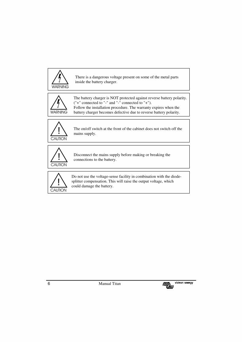
The battery charger is NOT protected against reverse battery polarity.
("+" connected to "-" and "-" connected to "+").
Follow the installation procedure. The warranty expires when the
battery charger becomes defective due to reverse battery polarity.
There is a dangerous voltage present on some of the metal parts
inside the battery charger.
The on/off switch at the front of the cabinet does not switch off the
mains supply.
Disconnect the mains supply before making or breaking the
connections to the battery.
Do not use the voltage-sense facility in combination with the diode-
splitter compensation. This will raise the output voltage, which
could damage the battery.

Manual Titan 7
2. DESCRIPTION
2.1 The Titan battery charger
The Titan battery charger is a fully automatic charger for 12V, 24V or 48V batteries and is
powered by a mains voltage of 230Vac, 50Hz or 110Vac, 50 Hz for the Skylla-Tg 24/30
110V. It charges the battery according to the IUoUo characteristic, which is a 3-stage
charging characteristic. This characteristic is shown in illustration 1. While charging, the
Titan continuously measures the battery voltage and current and bases the charging voltage
and current on the measured values.
Type Boost voltage Float voltage Minimal
voltage
12V / 50A 14,25 Vdc 13,25 Vdc 12,5 Vdc
24V / 30A 28,5 Vdc 26,5 Vdc 25 Vdc
24V / 30A 110V 28,5 Vdc 26,5 Vdc 25 Vdc
24V / 50A 28,5 Vdc 26,5 Vdc 25 Vdc
24V / 50A 3-Ph 28,5 Vdc 26,5 Vdc 25 Vdc
48V / 25A 57 Vdc 53 Vdc 50 Vdc
Assuming that the battery is discharged, the Titan charger starts charging in the boost-charge
mode. In this mode the battery is charged until the battery voltage reaches the boost voltage.
At this point the battery is charged to approximately 80% of its maximum capacity. This is the
end of the boost-charge mode and the Titan charger automatically switches to the equalize-
charge mode.
During the equalize-charge mode the charging voltage stays the same as the boost voltage but
the charge current slowly decreases. The duration of this mode is pre-selectable to 4, 8 or 12
hours. The standard time of the equalize-mode is 4 hours. After this time the Titan charger
automatically switches into the float-charge mode.
In the float-charge mode the charge voltage changes into the float voltage and the charge
current continues to decrease. This mode lasts for 20 hours.
After the float-charge mode the charger returns to the equalize-charge mode for 30 minutes,
this is to compensate for the normal leakage or self discharge of the battery.
Illustration 1.
The IUoUo charge
characteristic.
8 Manual Titan
The Titan charger can remain connected to the battery continuously, without gas formation
taking place, caused by overcharging. It is not necessary to disconnect the battery from the
charger during long time storage, for example during the winter storage of a ship. The Titan
charger will keep your battery in optimum condition under all circumstances and will prolong
the lifetime of your battery.
A parallel load connected to the battery can cause a voltage drop. The Titan charger
automatically switches into the boost-charge mode when the battery voltage drops below the
minimal voltage.
The Titan charger is equipped with a separate starter-battery connection to charge an extra
battery, like a starter-battery. You can use this battery for starting machines, like a boat engine
for this application.
The Titan charger has a stabilised output voltage. Therefore the Titan charger can also be used
as a DC power supply in applications where no battery is present.
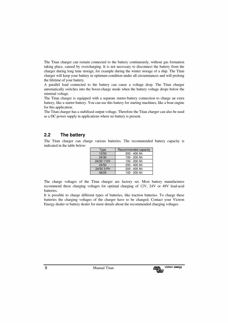
2.2 The battery
The Titan charger can charge various batteries. The recommended battery capacity is
indicated in the table below: Type Recommended capacity
12/50 200 - 400 Ah
24/30 100 - 200 Ah
24/30 110V 100 - 200 Ah
24/50 200 - 400 Ah
24/50 3-Ph 200 - 400 Ah
48/25 100 - 200 Ah
The charge voltages of the Titan charger are factory set. Most battery manufactures
recommend these charging voltages for optimal charging of 12V, 24V or 48V lead-acid
batteries.
It is possible to charge different types of batteries, like traction batteries. To charge these
batteries the charging voltages of the charger have to be changed. Contact your Victron
Energy dealer or battery dealer for more details about the recommended charging voltages.

Manual Titan 9
2.3 Protection
The battery charger is safe to use due to its robust design and its internal electronic
protection. This chapter describes the various internal electronic protective devices.
Maximum charge current protection � The battery charger provides a maximum charge current of 30A for the 30A models or
50A for the 50 A models. This level is electronically limited and is factory set.
� The maximum output current can also be limited by using an external potentiometer-
panel, the Victron Energy COV panel.
Short circuit protection � The charger output is protected against short-circuits. The short-circuit current is
electronically limited at 30A or 50A, according to the model. In this condition the output
voltage approaches 0 Volt. The battery charger resumes normal operation when the short
circuit is removed.
� The short circuit current can also be reduced by the Victron Energy COV panel.
Input protection
� The charger mains-input is protected with a fuse.
� The charger will not be damaged by using input voltage between 0 and 300 Vac.
� The charger will not be damaged by using input voltage frequency between 0 and 65
Hz.
Over voltage protection � The charger switches off automatically when the battery voltage becomes higher than the
over voltage value. The charger switches back on when the battery voltage becomes less
than the raise value. See the table below.
Model Over voltage value Raise value
12V 19,1 Vdc 18,1 Vdc
24V 35,5 Vdc 33,5 Vdc
48V 68,1 Vdc 64.1 Vdc
� The charger output is protected with a fuse.
Starter battery protection
� The output current of the starter battery output is electronically limited at 4A. The starter
battery output is also protected against wrong connections by means of a 10A fuse.

10 Manual Titan
Temperature protection � The internal temperature of the charger is measured continuously. However, due to a
high ambient temperature outside the cabinet the temperature within the battery
charger can rise. When the external temperature of the battery charger becomes higher
than 40°C, the output current decreases and the Failure led flashes.
� Before the internal temperature becomes too high due to extreme conditions the
charger switches off and the Failure led illuminates continuously. The charger resumes
operation when the internal temperature is restored within limits.
Voltage-sense protection
� When the voltage-sense facility is used the charger automatically decreases the output
voltage when the voltage loss over the battery cables is more than 2 Volt in total.
Battery watchdog timer � The charger is equipped with a battery watchdog timer. This timer measures the
duration of the boost mode. The moment the boost mode lasts longer than 10 hours,
the charger will switch to float mode. The charging voltage will then become the float
voltage. In this way it is prevented that a defective battery is needlessly charged with a
high charging voltage.
Manual Titan 11
3. DIRECTIONS FOR USE
3.1 Installation
Find a dry and well-ventilated area to mount the Titan charger and battery. Keep the distance
between the charger and the battery less than 6 meters.
The charger may be wall or floor mounted. Mounting on a wall improves the air circulation
within the charger cabinet and will prolong the lifetime of the battery charger.
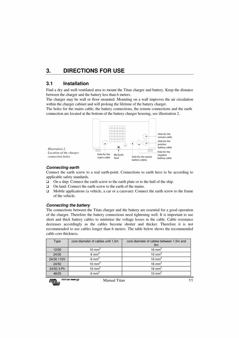
The holes for the mains cable, the battery connections, the remote connections and the earth
connection are located at the bottom of the battery charger housing, see illustration 2.
Connecting earth Connect the earth screw to a real earth-point. Connections to earth have to be according to
applicable safety standards.
� On a ship: Connect the earth screw to the earth plate or to the hull of the ship.
� On land: Connect the earth screw to the earth of the mains.
� Mobile applications (a vehicle, a car or a caravan): Connect the earth screw to the frame
of the vehicle.
Connecting the battery The connections between the Titan charger and the battery are essential for a good operation
of the charger. Therefore the battery connections need tightening well. It is important to use
short and thick battery cables to minimise the voltage losses in the cable. Cable resistance
decreases accordingly as the cables become shorter and thicker. Therefore it is not
recommended to use cables longer than 6 meters. The table below shows the recommended
cable core thickness.
Type core diameter of cables until 1,5m core diameter of cables between 1,5m and 6m
12/50 10 mm2 16 mm
2
24/30 6 mm2 10 mm
2
24/30 110V 6 mm2 10 mm
2
24/50 10 mm2 16 mm
2
24/50 3-Ph 10 mm2 16 mm
2
48/25 6 mm2 10 mm
2
Illustration 2,
Location of the charger
connection holes.
Hole for the
mains cableM6 Earth
Stud Hole for the starter
battery cables
Hole for the
remote cable
Hole for the
positive
battery cable
Hole for the
negative
battery cable
12 Manual Titan
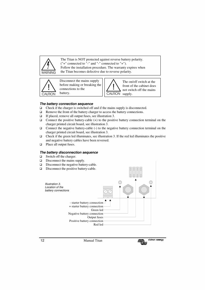
- starter battery connection
+ starter battery connection
Green led
Negative battery connection
Output fuses
Positive battery connection
Red led
The battery connection sequence � Check if the charger is switched off and if the mains supply is disconnected.
� Remove the front of the battery charger to access the battery connections.
� If placed, remove all output fuses, see illustration 3.
� Connect the positive battery-cable (+) to the positive battery connection terminal on the
charger printed circuit board, see illustration 3.
� Connect the negative battery-cable (-) to the negative battery connection terminal on the
charger printed circuit board, see illustration 3.
� Check if the green led illuminates, see illustration 3. If the red led illuminates the positive
and negative battery cables have been reversed.
� Place all output fuses.
The battery disconnection sequence
� Switch off the charger.
� Disconnect the mains supply.
� Disconnect the negative battery-cable.
� Disconnect the positive battery-cable.
The Titan is NOT protected against reverse battery polarity.
("+" connected to "-" and "-" connected to "+").
Follow the installation procedure. The warranty expires when
the Titan becomes defective due to reverse polarity.
.
Disconnect the mains supply
before making or breaking the
connections to the
battery.
Illustration 3. Location of the battery connections
The on/off switch at the
front of the cabinet does
not switch off the mains
supply.
Manual Titan 13
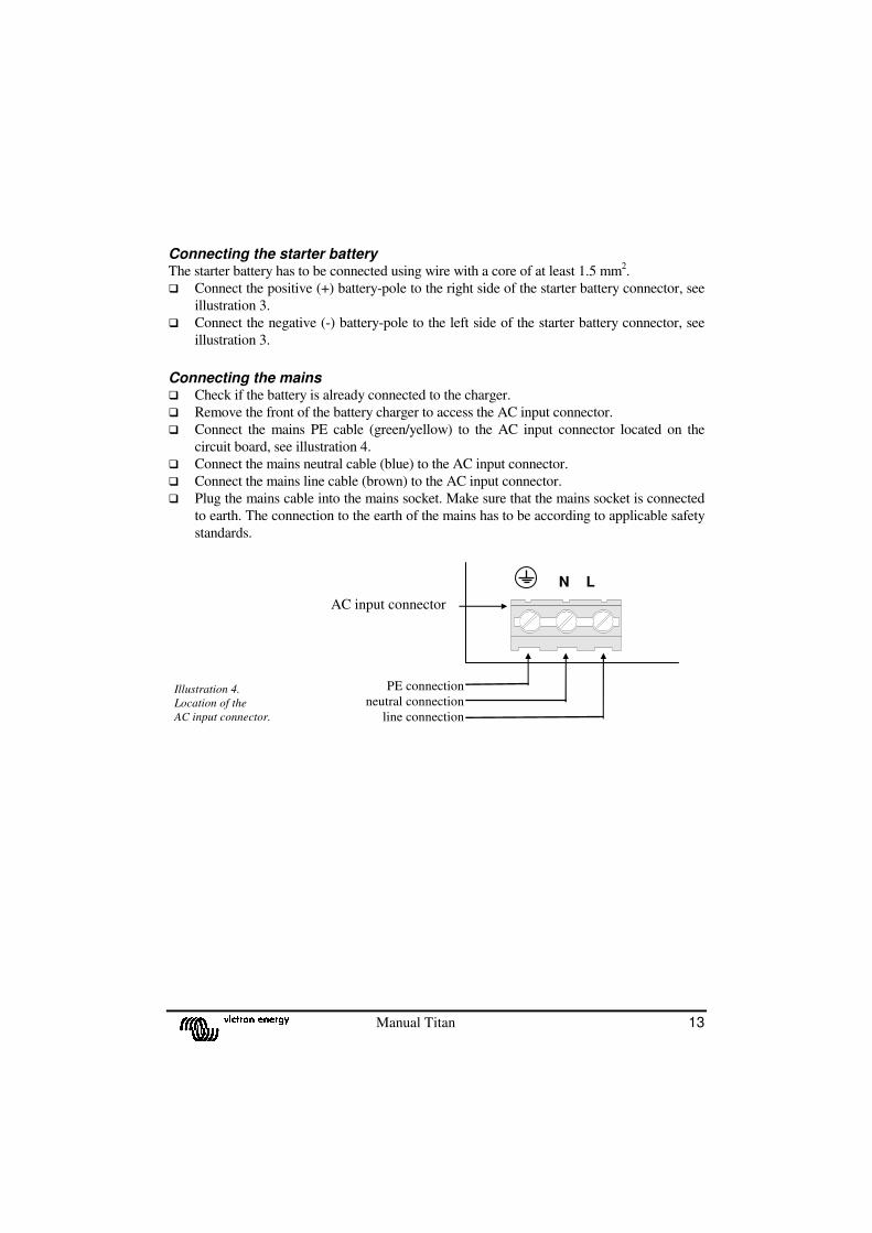
Connecting the starter battery The starter battery has to be connected using wire with a core of at least 1.5 mm
2.
� Connect the positive (+) battery-pole to the right side of the starter battery connector, see
illustration 3.
� Connect the negative (-) battery-pole to the left side of the starter battery connector, see
illustration 3.
Connecting the mains � Check if the battery is already connected to the charger.
� Remove the front of the battery charger to access the AC input connector.
� Connect the mains PE cable (green/yellow) to the AC input connector located on the
circuit board, see illustration 4.
� Connect the mains neutral cable (blue) to the AC input connector.
� Connect the mains line cable (brown) to the AC input connector.
� Plug the mains cable into the mains socket. Make sure that the mains socket is connected
to earth. The connection to the earth of the mains has to be according to applicable safety
standards.
Illustration 4.
Location of the
AC input connector.
AC input connector
N L
PE connection
neutral connection
line connection
14 Manual Titan
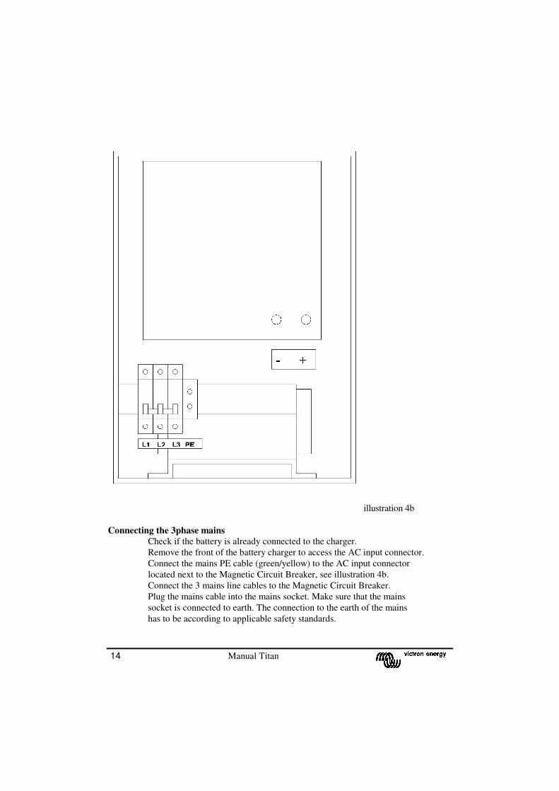
illustration 4b
Connecting the 3phase mains
� Check if the battery is already connected to the charger.
� Remove the front of the battery charger to access the AC input connector.
� Connect the mains PE cable (green/yellow) to the AC input connector
located next to the Magnetic Circuit Breaker, see illustration 4b.
� Connect the 3 mains line cables to the Magnetic Circuit Breaker.
� Plug the mains cable into the mains socket. Make sure that the mains
socket is connected to earth. The connection to the earth of the mains
has to be according to applicable safety standards.
Manual Titan 15
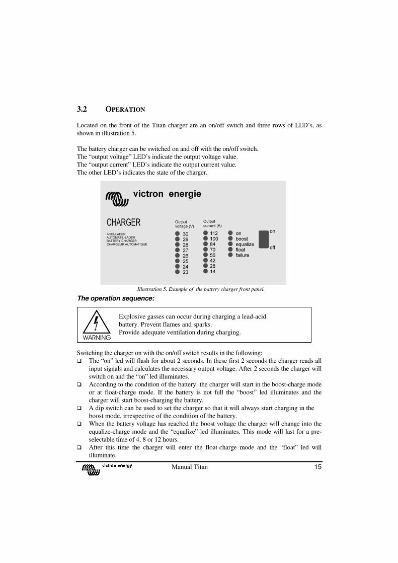
3.2 OPERATION Located on the front of the Titan charger are an on/off switch and three rows of LED’s, as
shown in illustration 5.
The battery charger can be switched on and off with the on/off switch.
The “output voltage” LED’s indicate the output voltage value.
The “output current” LED’s indicate the output current value.
The other LED’s indicates the state of the charger.
The operation sequence: Switching the charger on with the on/off switch results in the following:
� The “on” led will flash for about 2 seconds. In these first 2 seconds the charger reads all
input signals and calculates the necessary output voltage. After 2 seconds the charger will
switch on and the “on” led illuminates.
� According to the condition of the battery the charger will start in the boost-charge mode
or at float-charge mode. If the battery is not full the “boost” led illuminates and the
charger will start boost-charging the battery.
� A dip switch can be used to set the charger so that it will always start charging in the
boost mode, irrespective of the condition of the battery.
� When the battery voltage has reached the boost voltage the charger will change into the
equalize-charge mode and the “equalize” led illuminates. This mode will last for a pre-
selectable time of 4, 8 or 12 hours.
� After this time the charger will enter the float-charge mode and the “float” led will
illuminate.
Illustration 5. Example of the battery charger front panel.
Explosive gasses can occur during charging a lead-acid
battery. Prevent flames and sparks.
Provide adequate ventilation during charging.

16 Manual Titan
After the batteries are charged the Titan charger does not have to be switched off and the
batteries can stay connected to the battery charger.
3.3 Maintenance
The Titan charger does not require any specific maintenance. However an annual check of
the battery connections is recommended.
Keep the charger dry, clean and free of dust. If any problems arise, use the fault finding
procedure to trace the fault, see chapter 5.

Manual Titan 17
4. OPTIONS The Titan charger is factory set to standard values. Some of these standard values can be
changed by a qualified electrical technician into customised values. This chapter describes
which values can be changed and how to change them.
Opening of the battery charger cabinet In order to change the standard values the front of the charger has to be removed.
� Remove the AC plug from the mains and wait two minutes.
� Unscrew the 4 screws on the front of the cabinet, see illustration 6.
� Remove the front panel of the battery charger.
Adjustments can be made by means of turning a potentiometer or by changing the position of
a switch on the DIP-switch.
See illustration 7 for the location of the DIP-switch and the potentiometers.
Illustration 6.
Removing the front.
The cover of the Titan may only be removed by a qualified technician.
Before obtaining access to the Titan the mains supply circuit must be
disconnected.
There is a dangerous voltage present on some of the metal parts
inside the battery charger.
Attention ! The value of the potmeters I, Vboost and Vfloat may
only be adjusted by a qualified electrician. The remaining potmeters
may not be adjusted at any case.
Illustration 7.
Location of the DIP-switch and poteniometers.
I
Vboost
Vfloat
DIP switch

18 Manual Titan
4.1 Permanent boost-charge
In some cases, for example when the battery is almost empty, it is recommended to permanent
boost-charge the battery for 10 hours. Do not permanently boost-charge sealed lead-acid
batteries. Contact your Victron Energy dealer or battery dealer for more information on
charging the battery.
To set the charger into the permanent boost-charge mode: � Place the DIP switch number 8 “R boost” to the left. In this mode the
battery is being charged to the boost voltage.
� Do not permanent boost-charge the battery for longer than 10 hours as
this can cause long term gas formation in the battery and will damage
the battery.
� While a battery is being boost-charged, check the water level of the
battery frequently and if necessary add distilled water to the battery.
4.2 Adjusting the charge voltage
The battery charger has a factory set float and boost voltage. The boost-voltage is always
higher than the float-voltage. These charging voltages are the recommended values from
almost every battery manufacturer. Before adjusting the charge voltage disconnect the
temperature sensor and/or the voltage sense wires.
To change the float-voltage: � Remove all batteries and other users that are connected to the output
of the battery charger.
� Plug the AC plug into the mains and switch on the charger.
� Place DIP-switches 7 “Eq2” and 6 “Eq1” to the left position, this will
reduce the equalize time to 0 hours. The charger switches into the
float-charge mode.
� Place DIP-switch 4 “fine” to the left position in order to accurately
adjust the output voltage.
� Measure the float-voltage on the charger output by using a precision
voltage meter.
� Adjust the float-voltage by turning the “V float” potentiometer until
the recommended voltage is reached.
� Correct the equalize time by moving DIP-switch 7 “Eq2” and 6 “Eq1”.
� Place DIP-switch 4 “fine” to the right position. In this position the
output voltage is less sensitive to influence of temperature.

Manual Titan 19
To change the boost-voltage: � Place DIP-switch 7 “Eq2” to the right and place DIP-switch 8 “R
boost” to the left. The charger switches into the boost-charge mode.
� Place DIP-switch 4 “fine” to the left position in order to accurately
adjust the output voltage.
� Measure the boost-voltage on the charger output by using a precision
voltage meter.
� Adjust the boost-voltage by turning the “V boost” potentiometer
until the recommended voltage is reached.
� Replace DIP-switch 8 “R boost” to the right.
� Correct the equalize time by moving DIP-switch 7 “Eq2” and 6 “Eq1”.
� Place DIP-switch 4 “fine” to the right position. In this position the
output voltage is less sensitive to influence of temperature.
4.3 Adjusting the equalize-charging mode time
The duration of the equalize-charge mode can be changed to fit the specifications of the
battery. The duration of the equalize-charge mode can be set to 0, 4, 8 or 12 hours. When
selecting 0 hours, the charger will skip the equalize-charge mode and will directly switch
into the float-charge mode.
According to the table below the duration of the equalize-charge mode can be set by
moving the DIP-switches 7 “Eq2” and 6 “Eq1” in the corresponding way :
4.4 Diode-splitter charge voltage compensation.
If a diode-splitter (Victron Energy Argo) is connected to the Titan
charger the charging voltage have to be raised to compensate for the
voltage loss over the diode-splitter. If the voltage-sense option is used, it
is not recommended to use the diode-splitter compensation. When both
options are used simultaneously the output voltage will be too high.
To select the diode-splitter option:
� Place DIP switch 5 “split” to the left.
0 hours 4 hours 8 hours 12 hours
20 Manual Titan
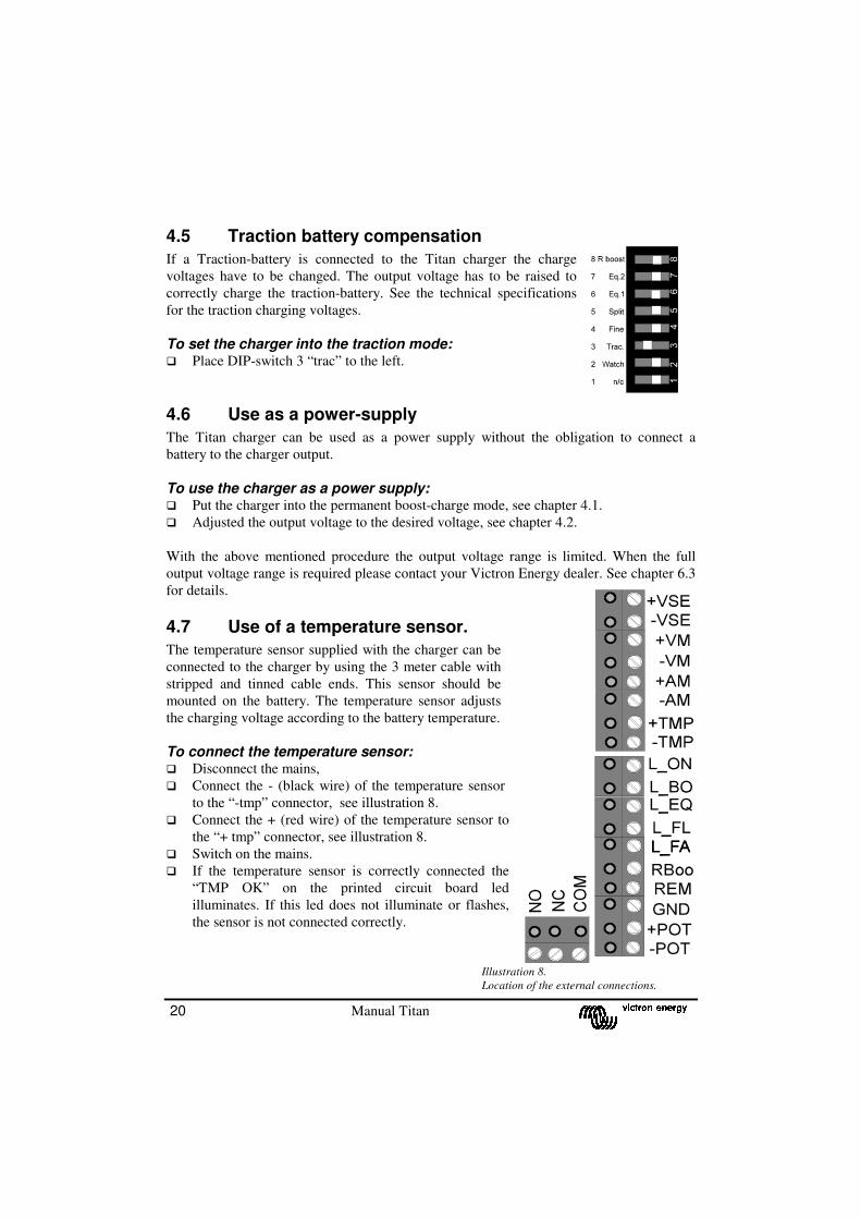
4.5 Traction battery compensation
If a Traction-battery is connected to the Titan charger the charge
voltages have to be changed. The output voltage has to be raised to
correctly charge the traction-battery. See the technical specifications
for the traction charging voltages.
To set the charger into the traction mode: � Place DIP-switch 3 “trac” to the left.
4.6 Use as a power-supply
The Titan charger can be used as a power supply without the obligation to connect a
battery to the charger output.
To use the charger as a power supply: � Put the charger into the permanent boost-charge mode, see chapter 4.1.
� Adjusted the output voltage to the desired voltage, see chapter 4.2.
With the above mentioned procedure the output voltage range is limited. When the full
output voltage range is required please contact your Victron Energy dealer. See chapter 6.3
for details.
4.7 Use of a temperature sensor.
The temperature sensor supplied with the charger can be
connected to the charger by using the 3 meter cable with
stripped and tinned cable ends. This sensor should be
mounted on the battery. The temperature sensor adjusts
the charging voltage according to the battery temperature.
To connect the temperature sensor: � Disconnect the mains,
� Connect the - (black wire) of the temperature sensor
to the “-tmp” connector, see illustration 8.
� Connect the + (red wire) of the temperature sensor to
the “+ tmp” connector, see illustration 8.
� Switch on the mains.
� If the temperature sensor is correctly connected the
“TMP OK” on the printed circuit board led
illuminates. If this led does not illuminate or flashes,
the sensor is not connected correctly.
Illustration 8.
Location of the external connections.
Manual Titan 21
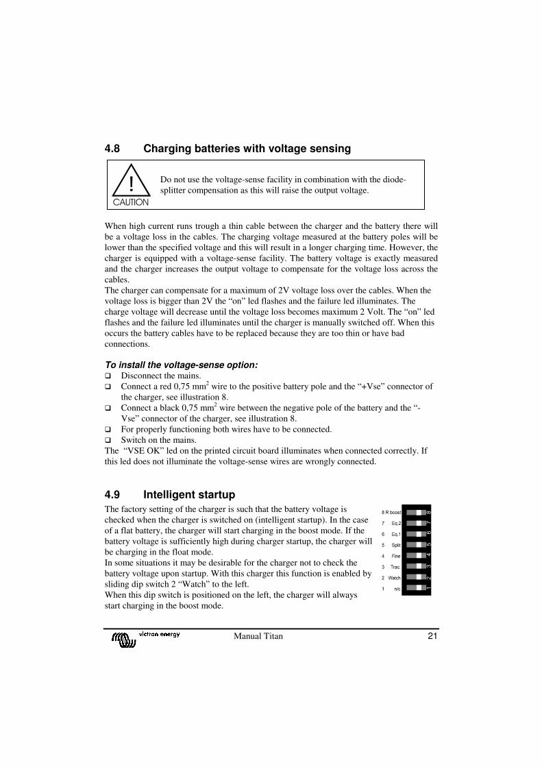
4.8 Charging batteries with voltage sensing
When high current runs trough a thin cable between the charger and the battery there will
be a voltage loss in the cables. The charging voltage measured at the battery poles will be
lower than the specified voltage and this will result in a longer charging time. However, the
charger is equipped with a voltage-sense facility. The battery voltage is exactly measured
and the charger increases the output voltage to compensate for the voltage loss across the
cables.
The charger can compensate for a maximum of 2V voltage loss over the cables. When the
voltage loss is bigger than 2V the “on” led flashes and the failure led illuminates. The
charge voltage will decrease until the voltage loss becomes maximum 2 Volt. The “on” led
flashes and the failure led illuminates until the charger is manually switched off. When this
occurs the battery cables have to be replaced because they are too thin or have bad
connections.
To install the voltage-sense option: � Disconnect the mains.
� Connect a red 0,75 mm2 wire to the positive battery pole and the “+Vse” connector of
the charger, see illustration 8.
� Connect a black 0,75 mm2 wire between the negative pole of the battery and the “-
Vse” connector of the charger, see illustration 8.
� For properly functioning both wires have to be connected.
� Switch on the mains.
The “VSE OK” led on the printed circuit board illuminates when connected correctly. If
this led does not illuminate the voltage-sense wires are wrongly connected.
4.9 Intelligent startup
The factory setting of the charger is such that the battery voltage is
checked when the charger is switched on (intelligent startup). In the case
of a flat battery, the charger will start charging in the boost mode. If the
battery voltage is sufficiently high during charger startup, the charger will
be charging in the float mode.
In some situations it may be desirable for the charger not to check the
battery voltage upon startup. With this charger this function is enabled by
sliding dip switch 2 “Watch” to the left.
When this dip switch is positioned on the left, the charger will always
start charging in the boost mode.
Do not use the voltage-sense facility in combination with the diode-
splitter compensation as this will raise the output voltage.

22 Manual Titan
When dip switch 2 “Watch” is positioned on the right, it is checked upon startup whether
the battery voltage is sufficiently high to enable a start in the float mode. If it is not, the
charger is started in the boost mode as yet.
4.10 Connecting the output voltage alarm
The charger is equipped with a potential free alarm contact (change over type).
If the battery voltage is between Vmin and Vmax the contact is activated.
(See figure 8, remote connections: NO, NC, COM).
Model Vmin Vmax
12V 11,9 Vdc 16,8 Vdc
24V 23,8 Vdc 33,5 Vdc
48V 47,6 Vdc 67 Vdc
4.11 Connecting remote panels
Victron Energy provides four optional remote panels that can be connected to the charger.
See illustration 8 for the circuit board connector where the remote panels have to be
connected to.
The COV panel: The maximum charging current of 30A or 50A, according to the model, can be limited with
an external panel. This panel, the Victron Energy COV panel, contains an adjustable
potentiometer. Limiting the maximum charging current can be useful to meet the batteries
specifications, or to make sure the shore fuse does not blow.
To connect the panel: � Disconnect the mains.
� Connect the panel to the “+ pot” and “-pot” connector.
The CMV panel: This panel indicates the charging mode and possible failures.
To connect the panel: � Disconnect the mains.
� Connect the boost led to the “ L_BO” connector.
� Connect the equalize led to the “L_EQ” connector.
� Connect the float led to the “L_FL” connector.
� Connect the failure led to the “L_FA” connector.
� Connect the ground of the panel to the “GND” connector.
The CSV panel: With the CSV panel the charger can be switched on or off. On the panel a green “on” led
is present. To operate the CSV panel you first have to switch the charger on with the on/off
switch located on the front panel of the charger.

Manual Titan 23
To connect he panel: � Disconnect the mains
� Connect the on led to the “L_ON” connector.
� Connect the ground of the panel to the “GND” connector.
� Connect the connection “TG switch” to the “REM” connector.
The SKC panel: This panel indicates if the charger is on or off, it indicates the charging mode and it
contains an adjustable potentiometer. Limiting the maximum charging current can be useful
to more accurately charge the batteries according the manufacturers specifications, or to
make sure the shore fuse does not blow.
To connect the panel: � Disconnect the mains
� Connect the on led to the “L_ON” connector.
� Connect the boost led to the “ L_BO” connector.
� Connect the float led to the “L_FL” connector.
� Connect the ground of the panel to the “GND” connector.
� Connect current control to the “+ POT” and “-POT” connector.
4.12 Connecting a remote on/off switch
A remote switch can be connected to the charger so the charger can be switched on and off
from a remote location. To operate the switch, first switch the charger on with the on/off
switch located on the charger.
To connect the remote on/off switch: � Disconnect the mains
� Connect the switch in between the “REM” and the “GND” connector.
4.13 Connecting a remote boost switch
A remote switch can be connected to the charger so the charger can be switched
permanently into the boost-charge mode. Due to parallel loads connected to the battery it is
advised to switch the charger into the permanent boost-charging mode in order not to
discharge the battery.
If the switch is closed the charger switches into the permanent boost-charge mode. If the
switch is opened again the charger will automatically go to the float-charge mode. This in
order not to overcharge a battery with charging it to long with higher charging voltage.
To connect the boost switch: � Disconnect the mains.
� Connect one pole of the switch to the “RBOO” connector.
� Connect the other pole of the switch to the “GND” connector.
24 Manual Titan
4.14 Connecting a voltmeter
The remote-connector offers a possibility to connect a voltmeter. It is possible to connect a
digital as well as a analogue voltmeter. This output can only be used when the voltage-
sense is connected. The voltage at this output is equal to the voltage measured at the point
where the voltage sense wires are connected.
Connecting a voltmeter � Disconnect the mains voltage.
� Make sure that the voltage sense wires are connected, see chapter 4.8.
� Connect a black wire between the “-” connection of the voltmeter and “-VM” at the
remote connector.
� Connect a red wire between the “+” connection of the voltmeter and “+VM” at the
remote connector.
� Connect the mains voltage.
4.15 Connecting a ampèremeter
The remote connector offers a possibility to connect an ampèremeter, which indicates the
output current of the charger. For the 30A models an ampèremeter, which indicates 30A at
60mV input voltage is required. For the 50A models an ampèremeter, which indicates 50A
at 60mV input voltage is required.
Connecting a ampèremeter � Disconnect the mains voltage.
� Connect a black wire between the “-” connection of the ampèremeter and “-AM” at the
remote connector.
� Connect a red wire between the “+” connection of the ampèremeter and “+AM” at the
remote connector.
� Connect the mains voltage.
Manual Titan 25
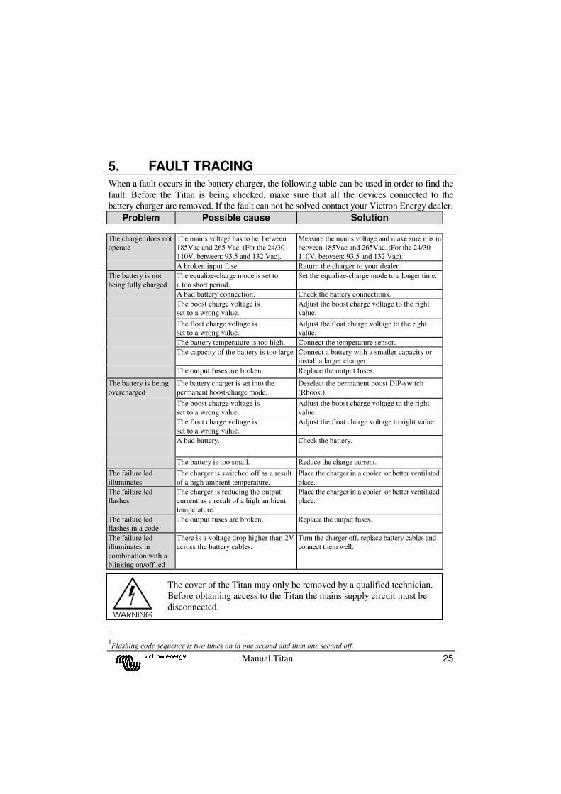
5. FAULT TRACING When a fault occurs in the battery charger, the following table can be used in order to find the
fault. Before the Titan is being checked, make sure that all the devices connected to the
battery charger are removed. If the fault can not be solved contact your Victron Energy dealer.
Problem Possible cause Solution
The charger does not
operate
The mains voltage has to be between
185Vac and 265 Vac. (For the 24/30
110V, between: 93,5 and 132 Vac).
Measure the mains voltage and make sure it is in
between 185Vac and 265Vac. (For the 24/30
110V, between: 93,5 and 132 Vac).
A broken input fuse. Return the charger to your dealer.
The battery is not
being fully charged
The equalize-charge mode is set to
a too short period.
Set the equalize-charge mode to a longer time.
A bad battery connection. Check the battery connections.
The boost charge voltage is
set to a wrong value.
Adjust the boost charge voltage to the right
value.
The float charge voltage is
set to a wrong value.
Adjust the float charge voltage to the right
value.
The battery temperature is too high. Connect the temperature sensor.
The capacity of the battery is too large. Connect a battery with a smaller capacity or
install a larger charger.
The output fuses are broken. Replace the output fuses.
The battery is being
overcharged
The battery charger is set into the
permanent boost-charge mode.
Deselect the permanent boost DIP-switch
(Rboost).
The boost charge voltage is
set to a wrong value.
Adjust the boost charge voltage to the right
value.
The float charge voltage is
set to a wrong value.
Adjust the float charge voltage to right value.
A bad battery. Check the battery.
The battery is too small. Reduce the charge current.
The failure led
illuminates
The charger is switched off as a result
of a high ambient temperature.
Place the charger in a cooler, or better ventilated
place.
The failure led
flashes
The charger is reducing the output
current as a result of a high ambient
temperature.
Place the charger in a cooler, or better ventilated
place.
The failure led
flashes in a code1
The output fuses are broken. Replace the output fuses.
The failure led
illuminates in
combination with a
blinking on/off led
There is a voltage drop higher than 2V
across the battery cables.
Turn the charger off, replace battery cables and
connect them well.
1Flashing code sequence is two times on in one second and then one second off.
The cover of the Titan may only be removed by a qualified technician.
Before obtaining access to the Titan the mains supply circuit must be
disconnected.
26 Manual Titan
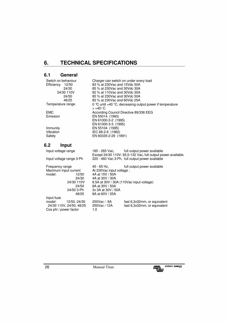
6. TECHNICAL SPECIFICATIONS
6.1 General Switch on behaviour Charger can switch on under every load Efficiency 12/50 24/30 24/30 110V 24/50 48/25
83 % at 230Vac and 15Vdc 50A 85 % at 230Vac and 30Vdc 30A 82 % at 110Vac and 30Vdc 30A 85 % at 230Vac and 30Vdc 50A 85 % at 230Vac and 60Vdc 25A
Temperature range 0 °C until +40 °C, decreasing output power if temperature > +40ºC
EMC According Council Directive 89/336 EEG Emission EN 55014 (1993)
EN 61000-3-2 (1995) EN 61000-3-3 (1995)
Immunity EN 55104 (1995) Vibration IEC 68-2-6 (1982) Safety EN 60335-2-29 (1991)
6.2 Input Input voltage range 185 - 265 Vac, full output power available
Except 24/30 110V: 93,5-132 Vac, full output power available. Input voltage range 3-Ph 320 - 460 Vac 3-Ph, full output power available
Frequency range 45 - 65 Hz, full output power available Maximum Input current model: 12/50 24/30 24/30 110V 24/50 24/50 3-Ph 48/25
At 230Vac input voltage : 4A at 15V / 50A 4A at 30V / 30A 8.5A at 30V / 30A (110Vac input voltage) 8A at 30V / 50A 3x 3A at 30V / 50A 8A at 60V / 25A
Input fuse model: 12/50, 24/30 24/30 110V, 24/50, 48/25
250Vac / 8A fast 6,3x32mm, or equivalent 250Vac / 12A fast 6,3x32mm, or equivalent
Cos phi / power factor 1,0

Manual Titan 27
6.3 OUTPUT Model TG 12/50 TG 24/30
24/30 110V TG 24/50 TG 24/50 3-Ph
TG 48/25
Boost charge voltage 14,25Vdc 28,50 Vdc 28,50 Vdc 57 Vdc Float charge voltage 13,25Vdc 26,50 Vdc 26,50 Vdc 53 Vdc
Output voltage range 12-16,5Vdc 24-33Vdc 24-33Vdc 48-66Vdc Output voltage range
supply mode2
0-16Vdc 0-33Vdc 0-33Vdc 0-66Vdc
Charge characteristic IUoUo IuoUo IUoUo IUoUo Model TG 12/50 TG 24/30
24/30 110V TG 24/50 TG 48/25
Voltage compensation for diode-splitter, via DIP-switch
+ 0,6 V + 0,6 V + 0,6 V + 0,6 V
Current/voltage stability ± 1 % ± 1 % ± 1 % ± 1 % Boost charge voltage compensation for traction battery, via DIP-switch
+ 1,0 V
+ 2,0 V
+ 2,0 V
+ 4,0 V
Maximum output current 50A 30A 50A 25A Output current range 0-50A 0-30A 0-50A 0-25A Output voltage ripple measured with a 30A or 50A resistive load
<100mVtt
<100mVtt
<100mVtt
<200mVtt
Maximum output power 750W 750W 1500W 1500W Short circuit current 55A 27,5A 55A 27,5A Maximum starter battery current
4A 4A 4A n/a
High battery alarm relay 16,8 Vdc ± 0,4Vdc
33.5Vdc ± 0,8Vdc
33.5Vdc ± 0,8Vdc
67 Vdc ± 1,6Vdc
Low battery alarm relay 11,9 Vdc ±0,4Vdc
23,8 Vdc ±0,8Vdc
23,8 Vdc ±0,8Vdc
47,6 Vdc ±1,6Vdc
Output fuse (flat car fuse) 4 x 20A 2 x 20A 4 x 20A other * Leakage current from battery when the battery charger is turned off
≤ 3,2 mA
≤ 3,2 mA
≤ 3,2 mA
≤ 3,2 mA
* 6,3mm x 32mm 30A fuse
2 Contact your Victron Energy dealer for this option.
28 Manual Titan
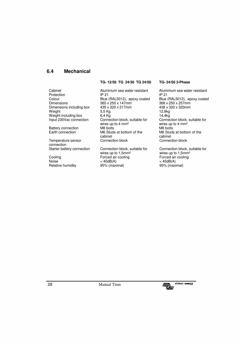
6.4 Mechanical
TG- 12/50 TG 24/30 TG 24/50 TG- 24/50 3-Phase Cabinet Aluminium sea water resistant Aluminium sea water resistant Protection IP 21 IP 21 Colour Blue (RAL5012), epoxy coated Blue (RAL5012), epoxy coated Dimensions 365 x 250 x 147mm 368 x 250 x 257mm Dimensions including box 435 x 320 x 217mm 438 x 320 x 320mm Weight 5,5 Kg 12.8kg Weight including box 6,4 Kg 14.4kg Input 230Vac connection Connection block, suitable for
wires up to 4 mm² Connection block, suitable for wires up to 4 mm²
Battery connection M8 bolts M8 bolts Earth connection M6 Studs at bottom of the
cabinet M6 Studs at bottom of the cabinet
Temperature sensor connection
Connection block Connection block
Starter battery connection Connection block, suitable for wires up to 1,5mm²
Connection block, suitable for wires up to 1,5mm²
Cooling Forced air cooling Forced air cooling Noise < 45dB(A) < 45dB(A) Relative humidity 95% (maximal) 95% (maximal)
Manual Titan 29
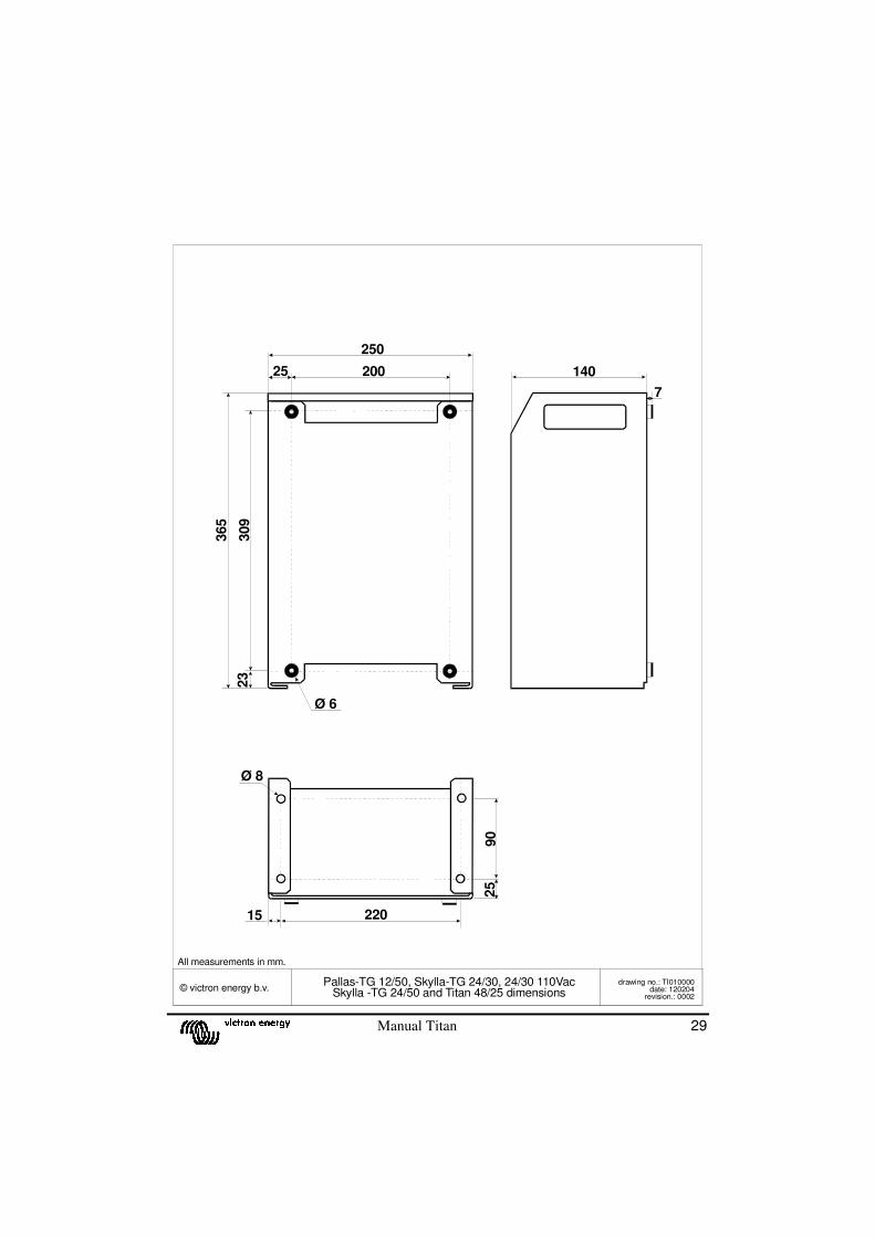
© victron energy b.v.Pallas-TG 12/50, Skylla-TG 24/30, 24/30 110Vac
Skylla -TG 24/50 and Titan 48/25 dimensionsdrawing no.: TI010000
date: 120204revision.: 0002
22015
7
Ø 8
Ø 6
250
25 200 140
90
365
309
23
25
All measurements in mm.

30 Manual Titan

Manual Titan 31
Victron Energy B.V. The Netherlands Phone: ++ 31 (0) 36 535 97 00 Fax: ++ 31 (0) 36 531 16 66 E-mail: [email protected] Internet site: http://www.victronenergy.com Article number: ISM010026000 Doc. no.: TI01170gb Version: rev 03 Date: 15-02-2010
STOCK NUMBER:
DEALER: