Embed Size (px)
Citation preview
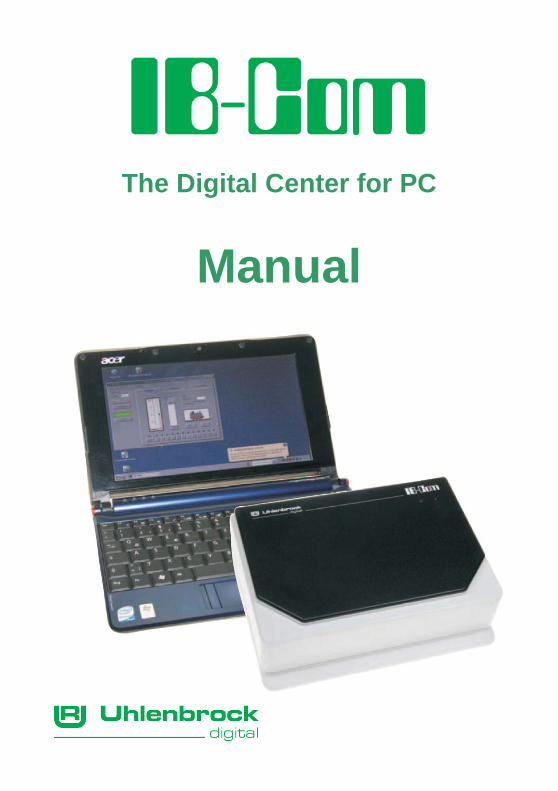
The Digital Center for PC
Manual
IB-COM
2
Table of Contents 1. The Digital Center IB-COM .................................................... 3
1.1 Description....................................................................................... 3 1.2 Technical Data................................................................................. 4
2. The Interface........................................................................... 5 2.1 Interface Characteristics .................................................................. 5 2.2 Preparation for installating the driver ............................................... 5 2.3 Installation of Driver software on Windows 2000............................. 6 2.4 Installation of Driver software on Windows VISTA ........................ 14 2.5 Installation of Driver software on Windows XP.............................. 18 2.6 Using the Interface......................................................................... 21 2.7 Interface Configuration .................................................................. 21 2.8 Communication PC – LocoNet (only for Experts) .......................... 22 2.10 LocoNet Direct Mode................................................................... 22
3. The IB-COM connectors ...................................................... 23 3.1 Definition of the IB-COM connectors ............................................. 23 3.2 Preparation of the clamp plugs...................................................... 23 3.3 Connecting transformer, track and programming track ................. 24 3.4 Connecting a DCC booster............................................................ 25 3.5 Connecting a LocoNet Booster...................................................... 25 3.6 Connecting LocoNet ...................................................................... 26 3.7 Connecting Computer Interface..................................................... 26
4. The Utility Software.............................................................. 27 4.1 The Workspace.............................................................................. 27 4.2 Settings – Basic Settings “Locomotive Data Format” .................... 27 4.3 Settings – Basic Settings “Solenoid Data Format” ........................ 28 4.4 Settings – Basic Settings “Optional Settings” ................................ 29 4.5 Settings – “Locomotive Data Format Individual”............................ 29 4.6 Settings – “Special Options” .......................................................... 30 4.7 Settings – “Serial and Version Numbers” ...................................... 30 4.8 Settings – “Reset” .......................................................................... 31 4.9 Tools – “DCC Decoder Programming” .......................................... 31 4.10 Tools – “LocoNet Module Programming”..................................... 33
5. Software Update................................................................... 36 Appendix................................................................................... 37
List of Special options.......................................................................... 38 Module address table for feedback channels ...................................... 39 Converting bits to bytes ....................................................................... 40 Coding table for solenoid decoder ....................................................... 42 Tips and Tricks .................................................................................... 43 Troubleshooting ................................................................................... 45
HOTLINE ................................................................................... 46
All trademarks used are registered by the respective companies.
IB-COM
3
1. The Digital Center IB-COM The IB-COM is a digital center which is specifically designed for controlling model railways with a computer program. It can control layouts using the Motorola and DCC digital formats simultaneously, on the same track, and is therefore a genuine multi-protocol Digital system. It is extremely efficient and compact.
1.1 Description
With USB Interface The fast interface to the computer for controlling model railway layouts with computer programmes.
With Booster The high performance booster is short circuit proof. It has an output current of 3 A.
Various data formats
The IB-COM can control locomotive decoders and switch functions of most manufacturers mixed on a layout. The following data formats can be transmitted simultaneously:
Motorola data format Uhlenbrock, Märklin, Viessmann
Extended Motorola data format (Gauge I) Uhlenbrock, Märklin alternating current Gauge I format
DCC data format Uhlenbrock, Märklin direct current, Arnold, Digitrax, Lenz, LGB, Roco and all DCC compatible decoders.
9999 decoder addresses and 128 drive positions The IB-COM supports all addresses and speed steps of the various decoder makes.
Märklin Motorola Decoder 80 addresses, 14 speed steps
Uhlenbrock Motorola Decoder 255 addresses, 14 speed steps
Uhlenbrock DCC Decoder 9999 addresses, 128 speed steps
DCC compatible Decoder 99-9999 addresses, 14, 28, 128 speed steps, according to type
Extended special functions Up 10000 special functions (for some DCC decoders) are available for switching of light, sound, etc..
IB-COM
4
Non-Volatile memory All settings, which have been done with the IB-COM remain non-volatile, even if the equipment is switched off for months.
Updatable system software Using the IB-COM internal interface the system software can be updated at any time.
Compatible with many other devices On the back of the IB-COM are sockets for transformer, track, programming track, DCC booster, Roco and LGB Lokmaus1, s88 feedback modules, Digitrax LocoNet and the USB computer interface.
1.2 Technical Data Supply voltage AC input of 16-18 V. Maximum current load 3 A to the rails 0.2 A to LocoNet B output 0.5 A to LocoNet T output All outputs have short circuit protection. Maximum number of feedback modules A total of 2048 feedback contacts can be evaluated. Maximum number of loco addresses DCC format: 1-9999 Motorola format: 1-255 Maximum number of solenoid device decoder addresses DCC format: 1-2000 Motorola format: 1-320 Usable Transformers 52-100VA, max. 18V AC e.g. Uhlenbrock 70VA transformer, Part No. 20 070 Dimensions 180 x 136 x 80 mm
IB-COM
5
2. The Interface The computer interface refers to a USB computer interface. This type of interface is found on IBM-compatible PCs or laptops.
To connect the IB-COM (socket 5) with the USB interface use the Uhlenbrock USB cable Part No. 61070. That is a USB cable with connector types A and B plug, like you also use for connecting a USB printer.
The computer interface is set to a data transmission rate of 115200 Baud.
The USB LocoNet interface of the IB-COM can be used with the Windows Operating systems 2000, XP and Vista (32 bits, without active users access control (UAC)). Support for older Windows systems like 95 or 98 is not provided.
For layout control all PC-control programs that support LocoNet protocol can be used.
2.1 Interface Characteristics PC and LocoNet are electrically isolated. Baud rates of 19200, 38400, 57600 or 115200 Baud can be selected.
Two operating modes are available:
1. all bytes are passed directly to the LocoNet (only 19200 Baud)
2. only valid LocoNet Messages are transferred from the PC to LocoNet; the interface controls the data traffic on LocoNet; all Bytes from LocoNet are passed directly to the PC (factory setting).
2.2 Preparation for installating the driver Before you connect the IB-COM to the PC, the driver software for the interface must to be installed otherwise your PC may malfunction.
To install the driver insert the CD into your CD-ROM drive. After short time the program will start and guide you through the installation process for the software.
If the installation program does not automatically start, open the CD-ROM with File Manager or Explorer and start with a double click on “CDRUN.EXE”.
Precise instructions for the installation are found in the following sections for operating systems, Windows 2000, Windows Vista and Windows XP.
IB-COM
6
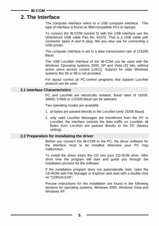
2.3 Installation of Driver software on Windows 2000 Start the installation with a double-click on “USB-LocoNet-Interface.exe“.
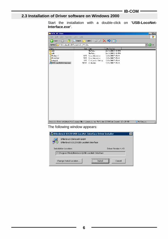
The following window appears:
IB-COM
7
If you want to change the path, click on “Change Install Location…“.
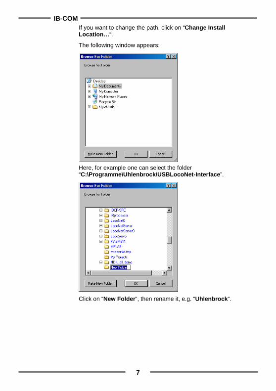
The following window appears:
Here, for example one can select the folder “C:\Programme\Uhlenbrock\USBLocoNet-Interface”.
Click on “New Folder“, then rename it, e.g. “Uhlenbrock“.
IB-COM
8
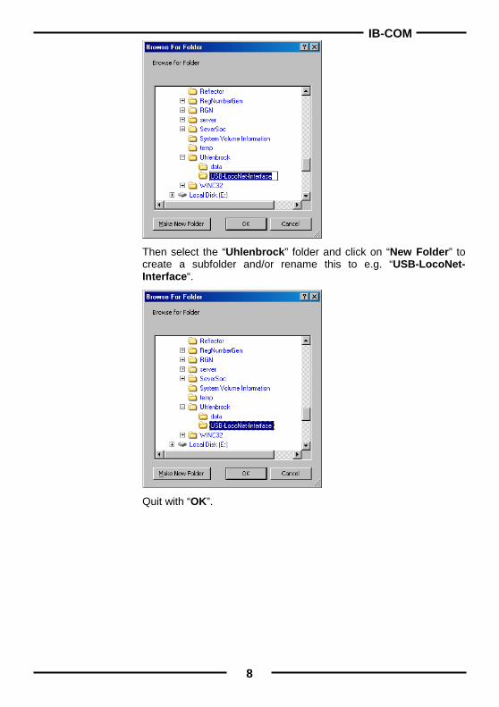
Then select the “Uhlenbrock” folder and click on “New Folder” to create a subfolder and/or rename this to e.g. “USB-LocoNet- Interface“.
Quit with “OK”.
IB-COM
9
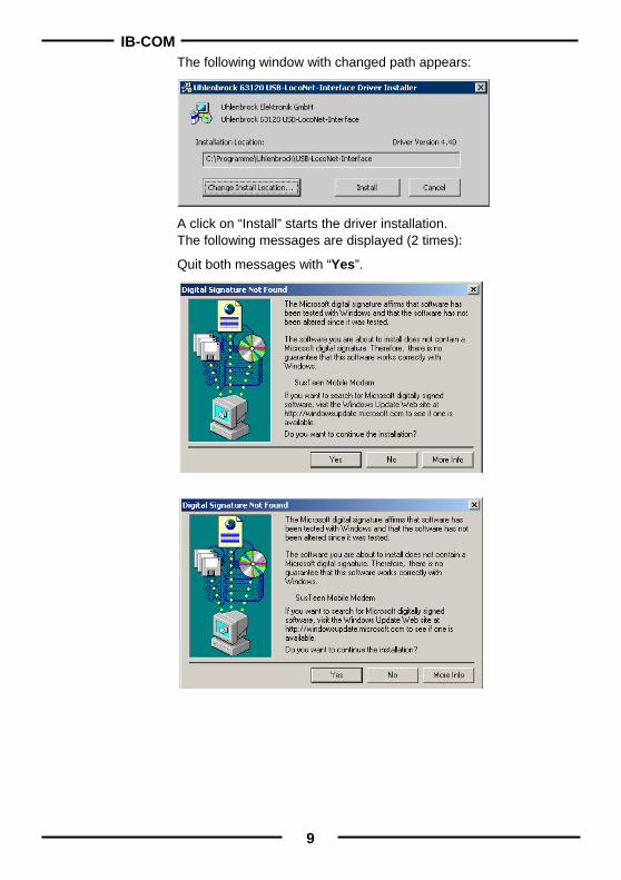
The following window with changed path appears:
A click on “Install” starts the driver installation. The following messages are displayed (2 times):
Quit both messages with “Yes”.
IB-COM
10
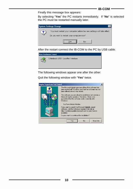
Finally this message box appears: By selecting “Yes” the PC restarts immediately. If “No” is selected the PC must be restarted manually later.
After the restart connect the IB-COM to the PC by USB cable.
The following windows appear one after the other:
Quit the following window with “Yes” twice.
IB-COM
11
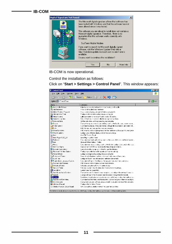
IB-COM is now operational.
Control the installation as follows: Click on “Start > Settings > Control Panel”. This window appears:
IB-COM
12
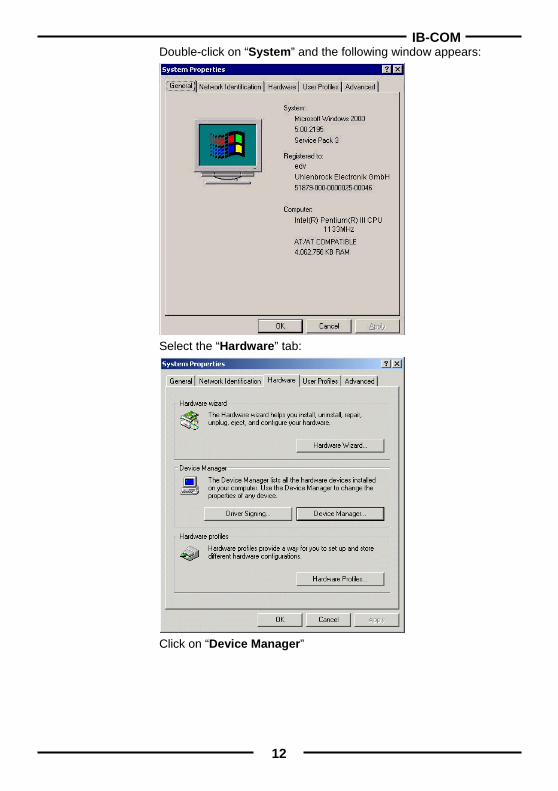
Double-click on “System” and the following window appears:
Select the “Hardware” tab:
Click on “Device Manager”
IB-COM
13
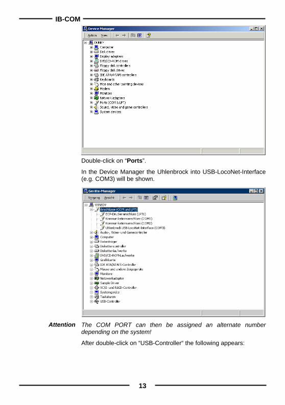
Double-click on “Ports”.
In the Device Manager the Uhlenbrock into USB-LocoNet-Interface (e.g. COM3) will be shown.
The COM PORT can then be assigned an alternate number depending on the system!
After double-click on “USB-Controller“ the following appears:
Attention
IB-COM
14
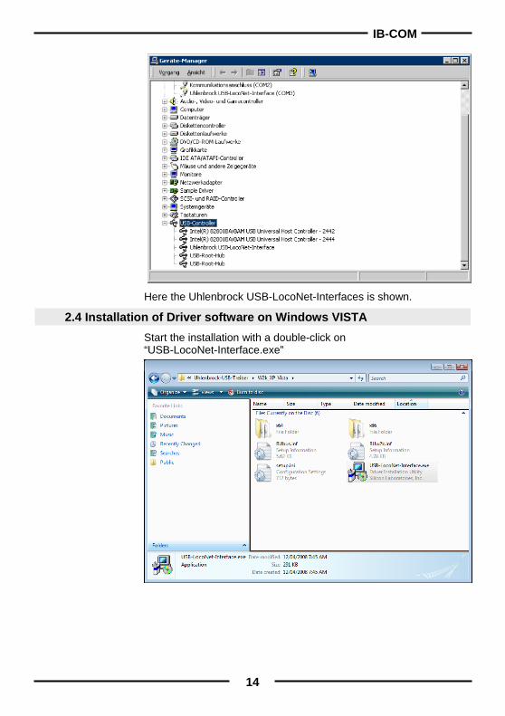
Here the Uhlenbrock USB-LocoNet-Interfaces is shown.
2.4 Installation of Driver software on Windows VISTA Start the installation with a double-click on “USB-LocoNet-Interface.exe”
IB-COM
15
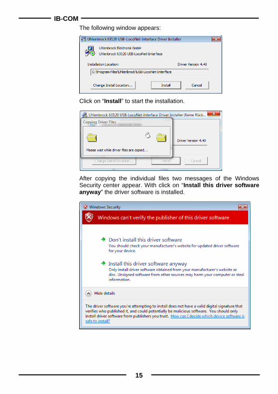
The following window appears:
Click on “Install” to start the installation.
After copying the individual files two messages of the Windows Security center appear. With click on “Install this driver software anyway” the driver software is installed.
IB-COM
16
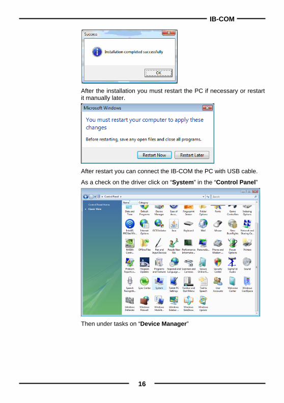
After the installation you must restart the PC if necessary or restart it manually later.
After restart you can connect the IB-COM the PC with USB cable.
As a check on the driver click on “System” in the “Control Panel”
Then under tasks on “Device Manager”
IB-COM
17
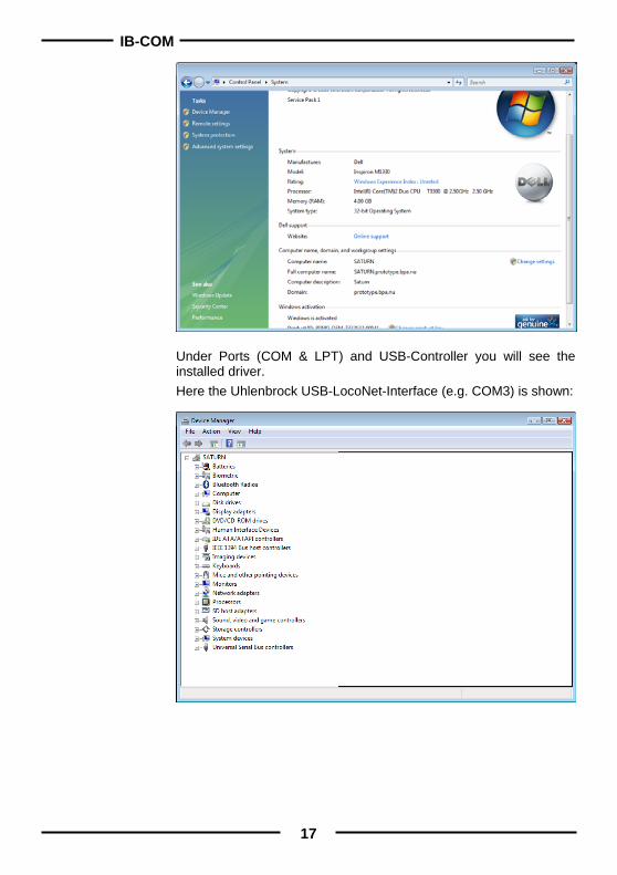
Under Ports (COM & LPT) and USB-Controller you will see the installed driver. Here the Uhlenbrock USB-LocoNet-Interface (e.g. COM3) is shown:
IB-COM
18
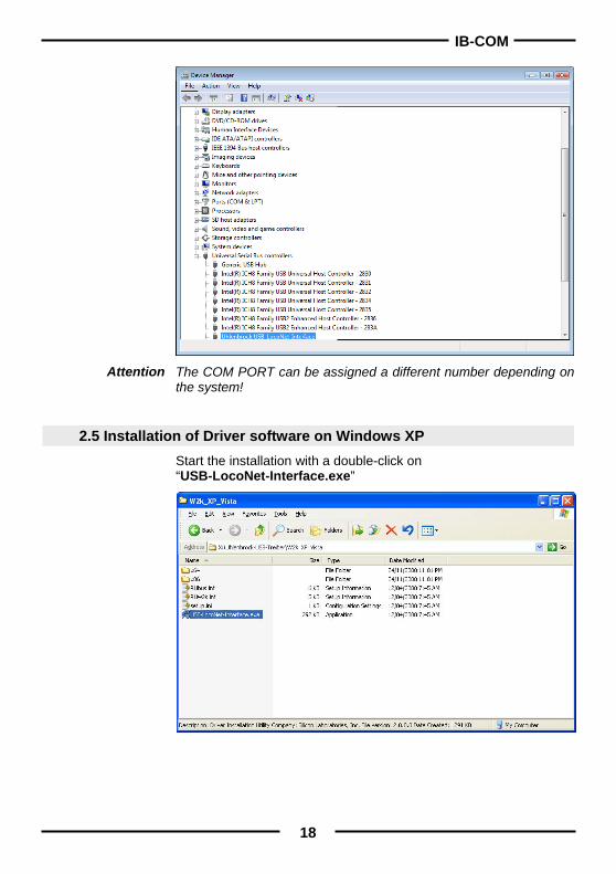
The COM PORT can be assigned a different number depending on the system!
2.5 Installation of Driver software on Windows XP Start the installation with a double-click on “USB-LocoNet-Interface.exe”
Attention
IB-COM
19
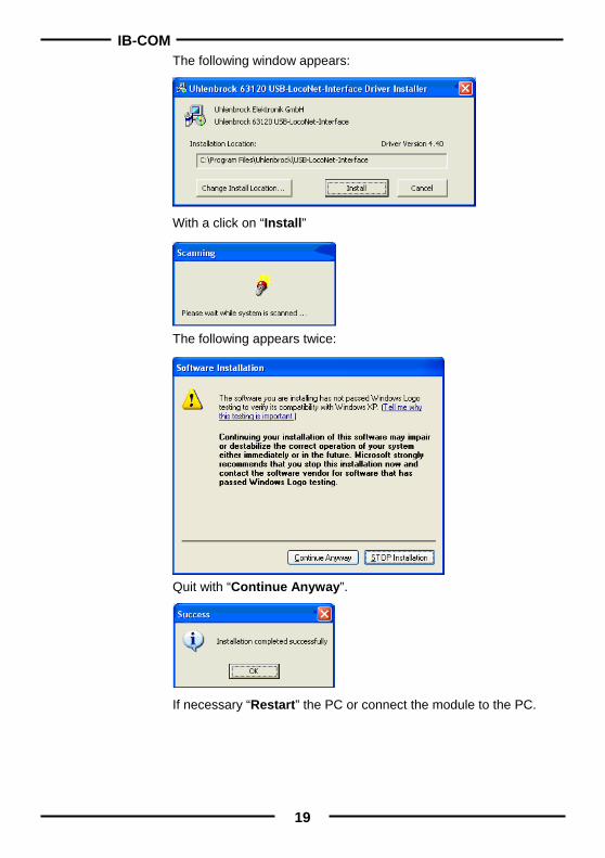
The following window appears:
With a click on “Install”
The following appears twice:
Quit with “Continue Anyway”.
If necessary “Restart” the PC or connect the module to the PC.
IB-COM
20
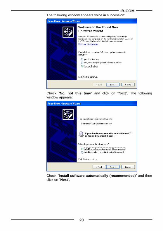
The following window appears twice in succession:
Check “No, not this time“ and click on “Next”. The following window appears:
Check “Install software automatically (recommended)” and then click on “Next”.
IB-COM
21
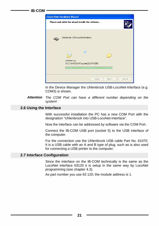
In the Device Manager the Uhlenbrock USB-LocoNet-Interface (e.g. COM3) is shown.
The COM Port can have a different number depending on the system!
2.6 Using the Interface With successful installation the PC has a new COM Port with the designation “Uhlenbrock into USB-LocoNet-Interface”.
Now the interface can be addressed by software via the COM Port.
Connect the IB-COM USB port (socket 5) to the USB interface of the computer.
For the connection use the Uhlenbrock USB cable Part No. 61070. It is a USB cable with an A and B type of plug, such as is also used for connecting a USB printer to the computer.
2.7 Interface Configuration Since the interface on the IB-COM technically is the same as the LocoNet interface 63120 it is setup in the same way by LocoNet programming (see chapter 4.3). As part number you use 63 120; the module address is 1.
Attention
IB-COM
22
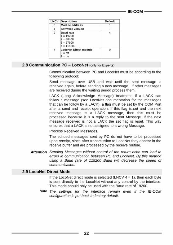
LNCV Description Default
0 Module address 1 1 Software version - 2 Baud rate
1 = 19200 2 = 38400 3 = 57600 4 = 115200
4
4 LocoNet Direct module 0 = off 1 = on
0
2.8 Communication PC – LocoNet (only for Experts)
Communication between PC and LocoNet must be according to the following protocol: Send message over USB and wait until the sent message is received again, before sending a new message. If other messages are received during the waiting period process them. LACK (Long Acknowledge Message) treatment: If a LACK can follow a message (see LocoNet documentation for the messages that can be follow by a LACK), a flag must be set by the COM Port after a send and receipt operation. If this flag is set and the next received message is a LACK message, then this must be processed because it is a reply to the sent Message. If the next message received is not a LACK the set flag is reset. This way ensures that a LACK is not assigned to a wrong Message. Process Received Messages. The echoed messages sent by PC do not have to be processed upon receipt, since after transmission to LocoNet they appear in the receive buffer and are processed by the receive routine.
Sending Messages without control of the return echo can lead to errors in communication between PC and LocoNet. By this method using a Baud rate of 115200 Baud will decrease the speed of communication.
2.9 LocoNet Direct Mode If the LocoNet direct mode is selected (LNCV 4 = 1), then each byte is sent directly to the LocoNet without any control by the interface. This mode should only be used with the Baud rate of 19200. The settings for the interface remain even if the IB-COM configuration is put back to factory default.
Attention
Note
IB-COM
23
Figure 3.11The rear of the IB-COM showing the
connections
3. The IB-COM connectors This chapter describes the connectors of the IB-COM and shows what must be taken into account when different devices are to be connected to the IB-COM.
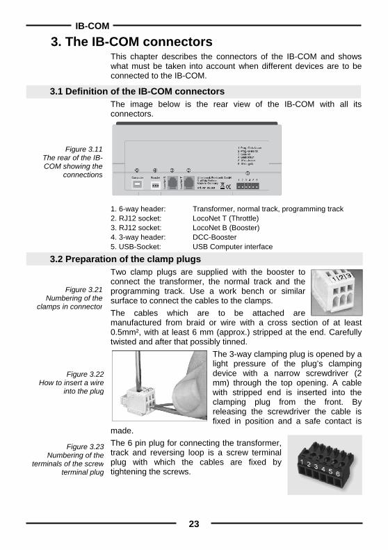
3.1 Definition of the IB-COM connectors The image below is the rear view of the IB-COM with all its connectors.
1. 6-way header: Transformer, normal track, programming track 2. RJ12 socket: LocoNet T (Throttle) 3. RJ12 socket: LocoNet B (Booster) 4. 3-way header: DCC-Booster 5. USB-Socket: USB Computer interface
3.2 Preparation of the clamp plugs Two clamp plugs are supplied with the booster to connect the transformer, the normal track and the programming track. Use a work bench or similar surface to connect the cables to the clamps. The cables which are to be attached are manufactured from braid or wire with a cross section of at least 0.5mm², with at least 6 mm (approx.) stripped at the end. Carefully twisted and after that possibly tinned.
The 3-way clamping plug is opened by a light pressure of the plug’s clamping device with a narrow screwdriver (2 mm) through the top opening. A cable with stripped end is inserted into the clamping plug from the front. By releasing the screwdriver the cable is fixed in position and a safe contact is
made. The 6 pin plug for connecting the transformer, track and reversing loop is a screw terminal plug with which the cables are fixed by tightening the screws.
Figure 3.21 Numbering of the
clamps in connector
Figure 3.22 How to insert a wire
into the plug
Figure 3.23 Numbering of the
terminals of the screw terminal plug
IB-COM
24
Figure 3.31 Connections of the
6-way connector
Figure 3.32 Connections to a
2-rails track
Figure 3.33 Connections to a
3-rails track
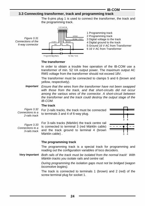
3.3 Connecting transformer, track and programming track The 6-pins plug 1 is used to connect the transformer, the track and the programming track.
1 Programming track 2 Programming track 3 Digital voltage to the track 4 Digital ground to the track 5 Ground 16 V AC from Transformer 6 16 V AC from Transformer
The transformer In order to obtain a trouble free operation of the IB-COM use a transformer of min. 52 VA output power. The maximum output AC RMS voltage from the transformer should not exceed 18V. The transformer must be connected to clamps 5 and 6 (brown and yellow, respectively). Ensure that the wires from the transformer have not been swapped with those from the track, and that short-circuits did not occur among the various wires of the connector. A short-circuit between the transformer and the track could destroy the output stage of the IB-COM. The track For 2-rails tracks, the track must be connected to terminals 3 and 4 of 6-way plug. For 3-rails tracks (Märklin) the track centre rail is connected to terminal 3 (red Märklin cable) and the track ground to terminal 4 (brown Märklin cable) .
The programming track The programming track is a special track for programming and reading out the configuration variables of loco decoders. Both rails of the track must be isolated from the normal track! With Märklin tracks you isolate rails and centre rail. During programming the isolation gaps must not be bridged (wagon locomotive bogies). The track is connected to terminals 1 (brown) and 2 (red) of the screw terminal plug for socket 1.
Important
Very Important
IB-COM
25
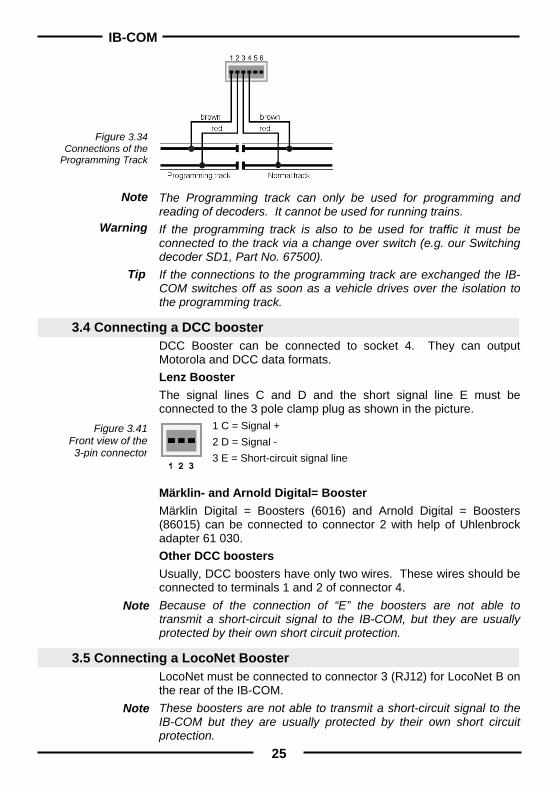
Figure 3.34 Connections of the
Programming Track
Figure 3.41 Front view of the 3-pin connector
The Programming track can only be used for programming and reading of decoders. It cannot be used for running trains. If the programming track is also to be used for traffic it must be connected to the track via a change over switch (e.g. our Switching decoder SD1, Part No. 67500). If the connections to the programming track are exchanged the IB-COM switches off as soon as a vehicle drives over the isolation to the programming track.
3.4 Connecting a DCC booster DCC Booster can be connected to socket 4. They can output Motorola and DCC data formats. Lenz Booster The signal lines C and D and the short signal line E must be connected to the 3 pole clamp plug as shown in the picture.
1 C = Signal + 2 D = Signal - 3 E = Short-circuit signal line
Märklin- and Arnold Digital= Booster Märklin Digital = Boosters (6016) and Arnold Digital = Boosters (86015) can be connected to connector 2 with help of Uhlenbrock adapter 61 030. Other DCC boosters Usually, DCC boosters have only two wires. These wires should be connected to terminals 1 and 2 of connector 4. Because of the connection of “E” the boosters are not able to transmit a short-circuit signal to the IB-COM, but they are usually protected by their own short circuit protection.
3.5 Connecting a LocoNet Booster LocoNet must be connected to connector 3 (RJ12) for LocoNet B on the rear of the IB-COM. These boosters are not able to transmit a short-circuit signal to the IB-COM but they are usually protected by their own short circuit protection.
Note
Warning
Note
Note
Tip
IB-COM
26
3.6 Connecting LocoNet All presently known LocoNet devices can be connected to the IB-COM. The LocoNet Booster must be connected to the LocoNet connector B (Socket 3). LocoNet control panels. LocoNet throttles and other LocoNet control devices should be connected to the LocoNet connector T (Socket 2) which delivers no digital track signal.
3.7 Connecting Computer Interface Before you connect the IB-COM to the PC the driver software for the interface must be installed (see chapter 2), otherwise your PC may malfunction. The computer interface is a USB Computer socket. This interface is found on IBM-compatible PCs or laptops. Use Uhlenbrock USB cable Part No. 61 070 to connect the IB-COM (socket 5) with the USB interface of the computer. That is a USB cable with A and B type plugs as it is also used for connecting a computer with a USB printer. The computer interface is set to a data transmission rate of 115200 Baud.
Note
IB-COM
27
4. The Utility Software Before the first use of the device you must install the USB driver (see chapters 2) and the program IB_Util.exe.
The program “IB_Util.exe” is to be found on the equipment enclosed utility CD. It makes the connection to the interface of the IB-COM and puts the following functionality at your disposal:
a Workspace with driving desk, keyboard and feedback monitor, which you can use for simple driving and switching tasks,
the Settings menu, with the data format, special options and device Reset submenus,
the Tools menu, for easy programming of DCC decoders and LocoNet modules.
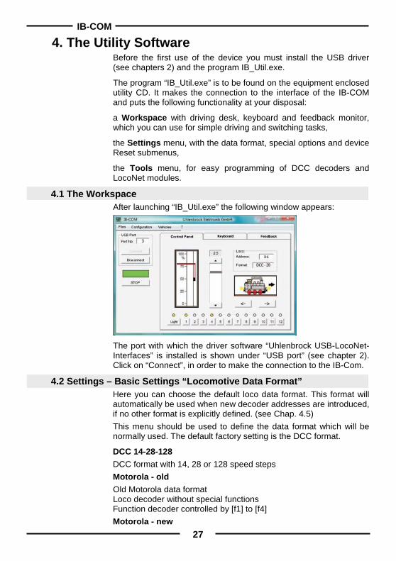
4.1 The Workspace After launching “IB_Util.exe” the following window appears:
The port with which the driver software “Uhlenbrock USB-LocoNet-Interfaces” is installed is shown under “USB port” (see chapter 2). Click on “Connect”, in order to make the connection to the IB-Com.
4.2 Settings – Basic Settings “Locomotive Data Format” Here you can choose the default loco data format. This format will automatically be used when new decoder addresses are introduced, if no other format is explicitly defined. (see Chap. 4.5) This menu should be used to define the data format which will be normally used. The default factory setting is the DCC format.
DCC 14-28-128 DCC format with 14, 28 or 128 speed steps Motorola - old Old Motorola data format Loco decoder without special functions Function decoder controlled by [f1] to [f4] Motorola - new
IB-COM
28
Also called Gauge 1 Format, with locomotive special functions f1 to f4. • Start “IB_Util.exe” • Operate “Connect” • Select the “Basic Settings” under the “Settings” menu • The window for Basic Settings appears • Select the desired locomotive data format “in the roll menu” • Input with the button „attitudes take over “confirm The digital format of each locomotive can be modified independently of all other locomotives under the “Settings – Locomotive Data Format individual” menu.
4.3 Settings – Basic Settings “Solenoid Data Format” Here you configure the data format to be used by solenoid decoders for all switching addresses before IB-COM is first used.
The DCC or Motorola data format are available. The default is the DCC data format.
Procedure: • Start “IB_Util.exe” • Operate “Connect” • Select the “Basic Settings” under the “Settings” menu • The window for Basic Settings appears • Select the desired locomotive data format “in the roll menu” • Input with the button „attitudes take over “confirm Switching decoders in Motorola Format: Uhlenbrock, Märklin, Viessmann, Modeltreno
Switching decoders in DCC Format: Uhlenbrock, Roco, Arnold, LGB, Lenz, Märklin=, Digitrax, etc.
Solenoid device decoders from Märklin, Viessmann and Modeltreno are compatible with the Motorola format. Their addresses are defined using the DIP switches that can be found inside each unit. Each decoder is characterized by a unique address. All Intellibox setup menus make use of these turnout addresses and not the solenoid decoder address. The appendix has a table which shows the relationship between the DIP switch position and the turnout addresses, as well as the allocation for the Märklin keyboard.
Note
Attention
IB-COM
29
4.4 Settings – Basic Settings “Optional Settings” If desired other settings can be changed in the Basic Settings menu.
On-time for solenoids When a solenoid is switched, two instructions are required, one to switch the solenoid on, and the other in order to switch the solenoid off again. If these Instructions are given to the center directly after one another without a pause the center will switch the solenoid on for the adjustable “minimum switch-on time”. If however only a switch on instruction is sent and no switch off instruction, the center independently switches the solenoid off after the “maximum Switch-on time”, in order to prevent an overload of the solenoid.
Number of Packets sent per instruction If the DCC data format for the control of solenoids is used then the number of packets sent by the center per solenoid instruction can be configured here. Solenoid decoders that do not immediately react can possibly be induced to operate by an increase of this setting.
“STOP” – status If this option is ticked the IB-COM powers up in the “STOP” state with track power switched off.
4.5 Settings – “Locomotive Data Format Individual”
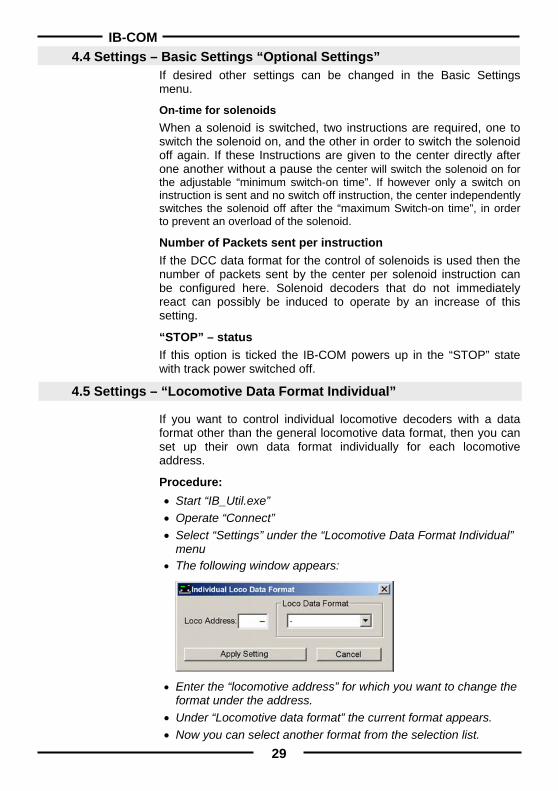
If you want to control individual locomotive decoders with a data format other than the general locomotive data format, then you can set up their own data format individually for each locomotive address.
Procedure: • Start “IB_Util.exe” • Operate “Connect” • Select “Settings” under the “Locomotive Data Format Individual”
menu • The following window appears:
• Enter the “locomotive address” for which you want to change the format under the address.
• Under “Locomotive data format” the current format appears. • Now you can select another format from the selection list.
IB-COM
30
• With the “Accept Setting” button the data format is transferred to the IB-COM.
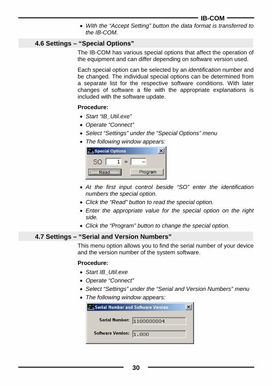
4.6 Settings – “Special Options” The IB-COM has various special options that affect the operation of the equipment and can differ depending on software version used.
Each special option can be selected by an identification number and be changed. The individual special options can be determined from a separate list for the respective software conditions. With later changes of software a file with the appropriate explanations is included with the software update.
Procedure: • Start “IB_Util.exe” • Operate “Connect” • Select “Settings” under the “Special Options” menu • The following window appears:
• At the first input control beside “SO” enter the identification numbers the special option.
• Click the “Read” button to read the special option. • Enter the appropriate value for the special option on the right
side. • Click the “Program” button to change the special option.
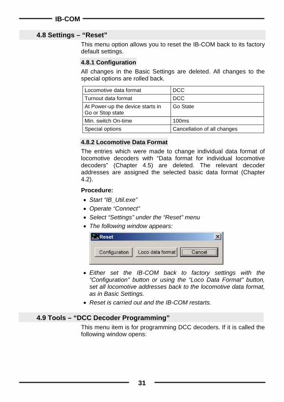
4.7 Settings – “Serial and Version Numbers” This menu option allows you to find the serial number of your device and the version number of the system software.
Procedure: • Start IB_Util.exe • Operate “Connect” • Select “Settings” under the “Serial and Version Numbers” menu • The following window appears:
IB-COM
31
4.8 Settings – “Reset”
This menu option allows you to reset the IB-COM back to its factory default settings.
4.8.1 Configuration All changes in the Basic Settings are deleted. All changes to the special options are rolled back.
Locomotive data format DCC Turnout data format DCC At Power-up the device starts in Go or Stop state
Go State
Min. switch On-time 100ms Special options Cancellation of all changes
4.8.2 Locomotive Data Format The entries which were made to change individual data format of locomotive decoders with “Data format for individual locomotive decoders” (Chapter 4.5) are deleted. The relevant decoder addresses are assigned the selected basic data format (Chapter 4.2).
Procedure: • Start “IB_Util.exe” • Operate “Connect” • Select “Settings” under the “Reset” menu • The following window appears:
• Either set the IB-COM back to factory settings with the “Configuration” button or using the “Loco Data Format” button, set all locomotive addresses back to the locomotive data format, as in Basic Settings.
• Reset is carried out and the IB-COM restarts.
4.9 Tools – “DCC Decoder Programming” This menu item is for programming DCC decoders. If it is called the following window opens:
IB-COM
32
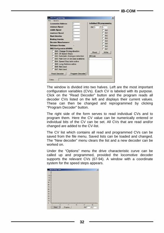
The window is divided into two halves. Left are the most important configuration variables (CVs). Each CV is labeled with its purpose. Click on the “Read Decoder” button and the program reads all decoder CVs listed on the left and displays their current values. These can then be changed and reprogrammed by clicking “Program Decoder” button.
The right side of the form serves to read individual CVs and to program them. Here the CV value can be numerically entered or individual bits of the CV can be set. All CVs that are read and/or changed are added to the CV-list.
The CV list which contains all read and programmed CVs can be saved from the file menu. Saved lists can be loaded and changed. The “New decoder” menu clears the list and a new decoder can be worked on.
Under the “Options” menu the drive characteristic curve can be called up and programmed, provided the locomotive decoder supports the relevant CVs (67-94). A window with a coordinate system for the speed steps appears.
IB-COM
33
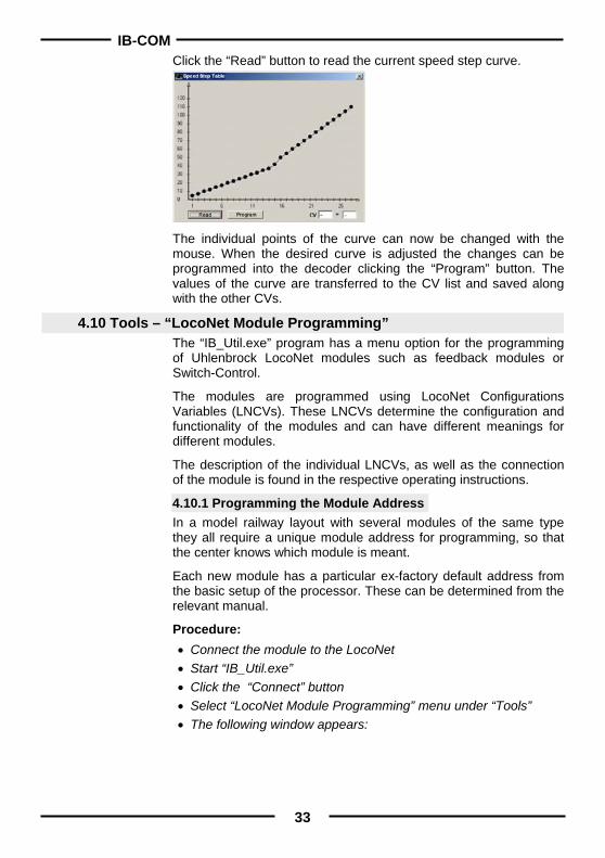
Click the “Read” button to read the current speed step curve.
The individual points of the curve can now be changed with the mouse. When the desired curve is adjusted the changes can be programmed into the decoder clicking the “Program” button. The values of the curve are transferred to the CV list and saved along with the other CVs.
4.10 Tools – “LocoNet Module Programming” The “IB_Util.exe” program has a menu option for the programming of Uhlenbrock LocoNet modules such as feedback modules or Switch-Control.
The modules are programmed using LocoNet Configurations Variables (LNCVs). These LNCVs determine the configuration and functionality of the modules and can have different meanings for different modules.
The description of the individual LNCVs, as well as the connection of the module is found in the respective operating instructions.
4.10.1 Programming the Module Address In a model railway layout with several modules of the same type they all require a unique module address for programming, so that the center knows which module is meant.
Each new module has a particular ex-factory default address from the basic setup of the processor. These can be determined from the relevant manual.
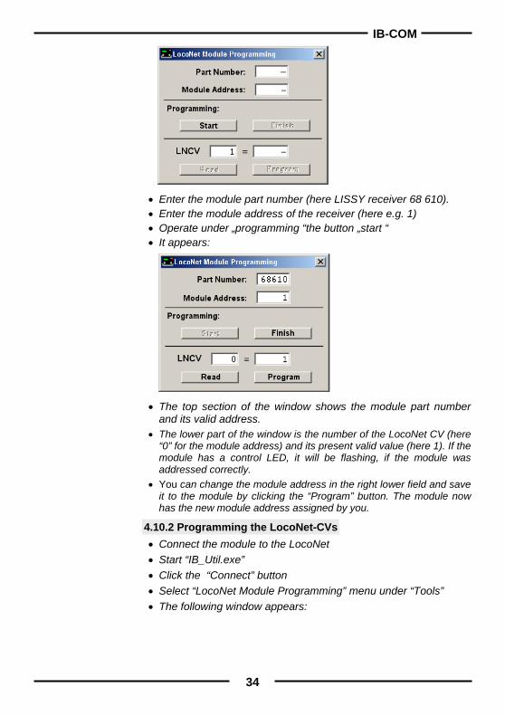
Procedure: • Connect the module to the LocoNet • Start “IB_Util.exe” • Click the “Connect” button • Select “LocoNet Module Programming” menu under “Tools” • The following window appears:
IB-COM
34
• Enter the module part number (here LISSY receiver 68 610). • Enter the module address of the receiver (here e.g. 1) • Operate under „programming “the button „start “ • It appears:
• The top section of the window shows the module part number and its valid address.
• The lower part of the window is the number of the LocoNet CV (here “0” for the module address) and its present valid value (here 1). If the module has a control LED, it will be flashing, if the module was addressed correctly.
• You can change the module address in the right lower field and save it to the module by clicking the “Program” button. The module now has the new module address assigned by you.
4.10.2 Programming the LocoNet-CVs • Connect the module to the LocoNet • Start “IB_Util.exe” • Click the “Connect” button • Select “LocoNet Module Programming” menu under “Tools” • The following window appears:

IB-COM
35
• Enter the Module part number (here LISSY receiver 68610) • Enter the modules address (here 1) • Click the “Program” button to start • This displays:
• Enter the Id number of the LocoNet CV which you would like to program in the lower left field.
• Click the “Read” button. The IB-COM reads the CV. The value is shown in the lower right field.
• Click with the mouse on the lower right field and enter the desired value for this CV.
• Click the “Program” button and the changed value is programmed. • Click the “Exit” button to terminate programming of the module.
Several LNCVs can be read and programmed before leaving the window.
Note
IB-COM
36
5. Software Update The IB-COM system software can be updated to a newer version, by downloading the new software from the computers, through the serial interfaces. There is no need to open up the IB-COM! Hardware requirement • You need to power the IB-COM with a transformer. • You will also need a serial cable to connect the IB-COM to a
Personal Computer. • Disconnect the IB-COM from the layout LocoNet. Software requirement Contact your local retailer to obtain the update of the new driver, or download it from our Internet site www.uhlenbrock.de.
Procedure • Switch the IB-COM off for 5 seconds and then on again • Start the program "IBCOMWinupdate.exe" and follow the
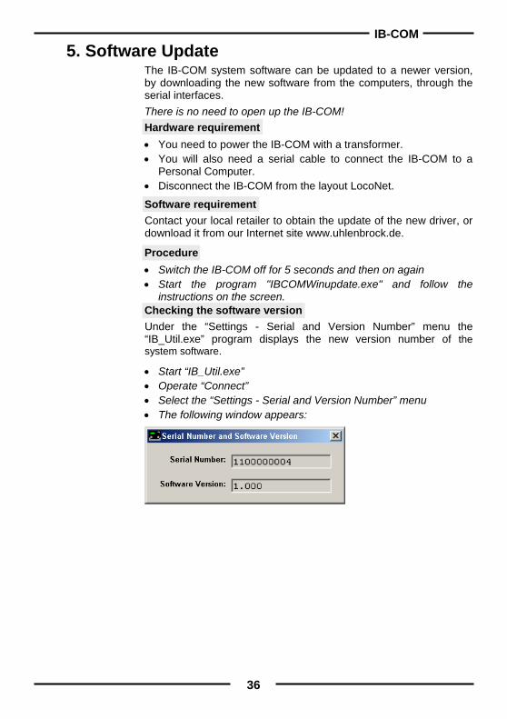
instructions on the screen. Checking the software version Under the “Settings - Serial and Version Number” menu the “IB_Util.exe” program displays the new version number of the system software.
• Start “IB_Util.exe” • Operate “Connect” • Select the “Settings - Serial and Version Number” menu • The following window appears:
IB-COM
37
Appendix
IB-COM
38
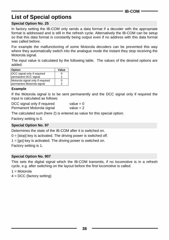
List of Special options Special Option No. 25 In factory setting the IB-COM only sends a data format if a decoder with the appropriate format is addressed and is still in the refresh cycle. Alternatively the IB-COM can be setup so that this data format is constantly being output even if no address with this data format was called before. For example the malfunctioning of some Motorola decoders can be prevented this way where they automatically switch into the analogue mode the instant they stop receiving the Motorola signal. The input value is calculated by the following table. The values of the desired options are added. Option Value DCC signal only if required permanent DCC signal
0 1
Motorola signal only if required permanent Motorola signal
0 2
Example If the Motorola signal is to be sent permanently and the DCC signal only if required the input is calculated as follows: DCC signal only if required value = 0 Permanent Motorola signal value = 2 The calculated sum (here 2) is entered as value for this special option. Factory setting is 0.
Special Option No. 97 Determines the state of the IB-COM after it is switched on. 0 = [stop] key is activated. The driving power is switched off. 1 = [go] key is activated. The driving power is switched on. Factory setting is 1.
Special Option No. 907 This sets the digital signal which the IB-COM transmits, if no locomotive is in a refresh cycle, e.g. after switching on the layout before the first locomotive is called. 1 = Motorola 4 = DCC (factory setting)
IB-COM
39
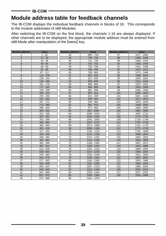
Module address table for feedback channels The IB-COM displays the individual feedback channels in blocks of 16. This corresponds to the module addresses of s88-Modules. After switching the IB-COM on the first block, the channels 1-16 are always displayed. If other channels are to be displayed, the appropriate module address must be entered from s88-Mode after manipulation of the m key.
Module address Input
1 1 - 16 2 17 - 32 3 33 - 48 4 49 - 64 5 65 - 80 6 81 - 95 7 97 - 112 8 113 - 128 9 129 - 144
10 145 - 160 11 161 - 176 12 177 - 192 13 193 - 208 14 209 - 224 15 225 - 240 16 241 - 256 17 257 - 272 18 273 - 288 19 289 - 304 20 305 - 320 21 321 - 336 22 337 - 352 23 353 - 368 24 369 - 384 25 385 - 400 26 401 - 416 27 417 - 432 28 433 - 448 29 449 - 464 30 465 - 480 31 481 - 496 32 497 - 512 33 513 - 528 34 529 - 544 35 545 - 560 36 561 - 576 37 577 - 592 38 593 - 608 39 609 - 624 40 625 - 640 41 641 - 656 42 657 – 672 43 673 - 688
Module address Input 44 689 – 704 45 705 - 720 46 721 - 736 47 737 - 752 48 753 - 768 49 769 - 784 50 785 - 800 51 801 - 816 52 817 - 832 53 833 - 848 54 849 - 864 55 865 - 880 56 881 - 896 57 897 - 912 58 913 – 928 59 929 - 944 60 945 - 960 61 961 - 976 62 977 - 992 63 993 - 1008 64 1009 - 1024 65 1025 - 1040 66 1041 - 1056 67 1057 - 1072 68 1073 - 1088 69 1089 – 1104 70 1105 - 1120 71 1121 - 1136 72 1137 - 1152 73 1153 - 1168 74 1169 - 1184 75 1185 - 1200 76 1201 - 1216 77 1217 - 1232 78 1233 - 1248 79 1249 - 1264 80 1265 - 1280 81 1281 - 1296 82 1297 – 1312 83 1313 - 1328 84 1329 - 1344 85 1345 - 1360 86 1361 - 1376
Module address Input 87 1377 - 1392 88 1393 - 1408 89 1409 - 1424 90 1425 - 1440 91 1441 - 1456 92 1457 - 1472 93 1473 - 1488 94 1489 - 1504 95 1505 - 1520 96 1521 - 1536 97 1537 - 1552 98 1553 - 1568 99 1569 – 1584
100 1585 - 1600 101 1601 – 1616 102 1617 - 1632 103 1633 - 1648 104 1649 - 1664 105 1665 - 1680 106 1681 - 1696 107 1697 - 1712 108 1713 - 1728 109 1729 – 1744 110 1745 – 1760 111 1761 – 1776 112 1777 – 1792 113 1793 – 1808 114 1809 - 1824 115 1825 - 1840 116 1841 - 1856 117 1857 - 1872 118 1873 - 1888 119 1889 - 1904 120 1905 - 1920 121 1921 - 1936 122 1937 - 1952 123 1953 - 1968 124 1969 - 1984 125 1985 - 2000 126 2001 - 2016 127 2017 - 2032 128 2033 - 2048
IB-COM
40
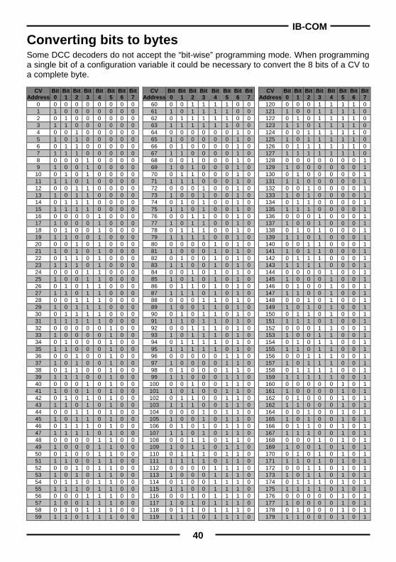
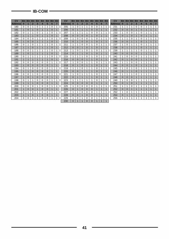
Converting bits to bytes Some DCC decoders do not accept the “bit-wise” programming mode. When programming a single bit of a configuration variable it could be necessary to convert the 8 bits of a CV to a complete byte.
CV Address
Bit 0
Bit 1
Bit 2
Bit 3
Bit 4
Bit 5
Bit6
Bit7
0 0 0 0 0 0 0 0 0 1 1 0 0 0 0 0 0 0 2 0 1 0 0 0 0 0 0 3 1 1 0 0 0 0 0 0 4 0 0 1 0 0 0 0 0 5 1 0 1 0 0 0 0 0 6 0 1 1 0 0 0 0 0 7 1 1 1 0 0 0 0 0 8 0 0 0 1 0 0 0 0 9 1 0 0 1 0 0 0 0
10 0 1 0 1 0 0 0 0 11 1 1 0 1 0 0 0 0 12 0 0 1 1 0 0 0 0 13 1 0 1 1 0 0 0 0 14 0 1 1 1 0 0 0 0 15 1 1 1 1 0 0 0 0 16 0 0 0 0 1 0 0 0 17 1 0 0 0 1 0 0 0 18 0 1 0 0 1 0 0 0 19 1 1 0 0 1 0 0 0 20 0 0 1 0 1 0 0 0 21 1 0 1 0 1 0 0 0 22 0 1 1 0 1 0 0 0 23 1 1 1 0 1 0 0 0 24 0 0 0 1 1 0 0 0 25 1 0 0 1 1 0 0 0 26 0 1 0 1 1 0 0 0 27 1 1 0 1 1 0 0 0 28 0 0 1 1 1 0 0 0 29 1 0 1 1 1 0 0 0 30 0 1 1 1 1 0 0 0 31 1 1 1 1 1 0 0 0 32 0 0 0 0 0 1 0 0 33 1 0 0 0 0 1 0 0 34 0 1 0 0 0 1 0 0 35 1 1 0 0 0 1 0 0 36 0 0 1 0 0 1 0 0 37 1 0 1 0 0 1 0 0 38 0 1 1 0 0 1 0 0 39 1 1 1 0 0 1 0 0 40 0 0 0 1 0 1 0 0 41 1 0 0 1 0 1 0 0 42 0 1 0 1 0 1 0 0 43 1 1 0 1 0 1 0 0 44 0 0 1 1 0 1 0 0 45 1 0 1 1 0 1 0 0 46 0 1 1 1 0 1 0 0 47 1 1 1 1 0 1 0 0 48 0 0 0 0 1 1 0 0 49 1 0 0 0 1 1 0 0 50 0 1 0 0 1 1 0 0 51 1 1 0 0 1 1 0 0 52 0 0 1 0 1 1 0 0 53 1 0 1 0 1 1 0 0 54 0 1 1 0 1 1 0 0 55 1 1 1 0 1 1 0 0 56 0 0 0 1 1 1 0 0 57 1 0 0 1 1 1 0 0 58 0 1 0 1 1 1 0 0 59 1 1 0 1 1 1 0 0
CV Address
Bit0
Bit1
Bit2
Bit3
Bit 4
Bit 5
Bit6
Bit7
60 0 0 1 1 1 1 0 0 61 1 0 1 1 1 1 0 0 62 0 1 1 1 1 1 0 0 63 1 1 1 1 1 1 0 0 64 0 0 0 0 0 0 1 0 65 1 0 0 0 0 0 1 0 66 0 1 0 0 0 0 1 0 67 1 1 0 0 0 0 1 0 68 0 0 1 0 0 0 1 0 69 1 0 1 0 0 0 1 0 70 0 1 1 0 0 0 1 0 71 1 1 1 0 0 0 1 0 72 0 0 0 1 0 0 1 0 73 1 0 0 1 0 0 1 0 74 0 1 0 1 0 0 1 0 75 1 1 0 1 0 0 1 0 76 0 0 1 1 0 0 1 0 77 1 0 1 1 0 0 1 0 78 0 1 1 1 0 0 1 0 79 1 1 1 1 0 0 1 0 80 0 0 0 0 1 0 1 0 81 1 0 0 0 1 0 1 0 82 0 1 0 0 1 0 1 0 83 1 1 0 0 1 0 1 0 84 0 0 1 0 1 0 1 0 85 1 0 1 0 1 0 1 0 86 0 1 1 0 1 0 1 0 87 1 1 1 0 1 0 1 0 88 0 0 0 1 1 0 1 0 89 1 0 0 1 1 0 1 0 90 0 1 0 1 1 0 1 0 91 1 1 0 1 1 0 1 0 92 0 0 1 1 1 0 1 0 93 1 0 1 1 1 0 1 0 94 0 1 1 1 1 0 1 0 95 1 1 1 1 1 0 1 0 96 0 0 0 0 0 1 1 0 97 1 0 0 0 0 1 1 0 98 0 1 0 0 0 1 1 0 99 1 1 0 0 0 1 1 0
100 0 0 1 0 0 1 1 0 101 1 0 1 0 0 1 1 0 102 0 1 1 0 0 1 1 0 103 1 1 1 0 0 1 1 0 104 0 0 0 1 0 1 1 0 105 1 0 0 1 0 1 1 0 106 0 1 0 1 0 1 1 0 107 1 1 0 1 0 1 1 0 108 0 0 1 1 0 1 1 0 109 1 0 1 1 0 1 1 0 110 0 1 1 1 0 1 1 0 111 1 1 1 1 0 1 1 0 112 0 0 0 0 1 1 1 0 113 1 0 0 0 1 1 1 0 114 0 1 0 0 1 1 1 0 115 1 1 0 0 1 1 1 0 116 0 0 1 0 1 1 1 0 117 1 0 1 0 1 1 1 0 118 0 1 1 0 1 1 1 0 119 1 1 1 0 1 1 1 0
CV Address
Bit0
Bit1
Bit2
Bit3
Bit4
Bit5
Bit 6
Bit 7
120 0 0 0 1 1 1 1 0 121 1 0 0 1 1 1 1 0 122 0 1 0 1 1 1 1 0 123 1 1 0 1 1 1 1 0 124 0 0 1 1 1 1 1 0 125 1 0 1 1 1 1 1 0 126 0 1 1 1 1 1 1 0 127 1 1 1 1 1 1 1 0 128 0 0 0 0 0 0 0 1 129 1 0 0 0 0 0 0 1 130 0 1 0 0 0 0 0 1 131 1 1 0 0 0 0 0 1 132 0 0 1 0 0 0 0 1 133 1 0 1 0 0 0 0 1 134 0 1 1 0 0 0 0 1 135 1 1 1 0 0 0 0 1 136 0 0 0 1 0 0 0 1 137 1 0 0 1 0 0 0 1 138 0 1 0 1 0 0 0 1 139 1 1 0 1 0 0 0 1 140 0 0 1 1 0 0 0 1 141 1 0 1 1 0 0 0 1 142 0 1 1 1 0 0 0 1 143 1 1 1 1 0 0 0 1 144 0 0 0 0 1 0 0 1 145 1 0 0 0 1 0 0 1 146 0 1 0 0 1 0 0 1 147 1 1 0 0 1 0 0 1 148 0 0 1 0 1 0 0 1 149 1 0 1 0 1 0 0 1 150 0 1 1 0 1 0 0 1 151 1 1 1 0 1 0 0 1 152 0 0 0 1 1 0 0 1 153 1 0 0 1 1 0 0 1 154 0 1 0 1 1 0 0 1 155 1 1 0 1 1 0 0 1 156 0 0 1 1 1 0 0 1 157 1 0 1 1 1 0 0 1 158 0 1 1 1 1 0 0 1 159 1 1 1 1 1 0 0 1 160 0 0 0 0 0 1 0 1 161 1 0 0 0 0 1 0 1 162 0 1 0 0 0 1 0 1 162 1 1 0 0 0 1 0 1 164 0 0 1 0 0 1 0 1 165 1 0 1 0 0 1 0 1 166 0 1 1 0 0 1 0 1 167 1 1 1 0 0 1 0 1 168 0 0 0 1 0 1 0 1 169 1 0 0 1 0 1 0 1 170 0 1 0 1 0 1 0 1 171 1 1 0 1 0 1 0 1 172 0 0 1 1 0 1 0 1 173 1 0 1 1 0 1 0 1 174 0 1 1 1 0 1 0 1 175 1 1 1 1 0 1 0 1 176 0 0 0 0 0 1 0 1 177 1 0 0 0 0 1 0 1 178 0 1 0 0 0 1 0 1 179 1 1 0 0 0 1 0 1
IB-COM
41
CV
Address Bit 0
Bit 1
Bit 2
Bit 3
Bit 4
Bit 5
Bit6
Bit7
180 0 0 1 0 1 1 0 1 181 1 0 1 0 1 1 0 1 182 0 1 1 0 1 1 0 1 183 1 1 1 0 1 1 0 1 184 0 0 0 1 1 1 0 1 185 1 0 0 1 1 1 0 1 186 0 1 0 1 1 1 0 1 187 1 1 0 1 1 1 0 1 188 0 0 1 1 1 1 0 1 189 1 0 1 1 1 1 0 1 190 0 1 1 1 1 1 0 1 191 1 1 1 1 1 1 0 1 192 0 0 0 0 0 0 1 1 193 1 0 0 0 0 0 1 1 194 0 1 0 0 0 0 1 1 195 1 1 0 0 0 0 1 1 196 0 0 1 0 0 0 1 1 197 1 0 1 0 0 0 1 1 198 0 1 1 0 0 0 1 1 199 1 1 1 0 0 0 1 1 200 0 0 0 1 0 0 1 1 201 1 0 0 1 0 0 1 1 202 0 1 0 1 0 0 1 1 203 1 1 0 1 0 0 1 1 204 0 0 1 1 0 0 1 1
CV
AddressBit0
Bit1
Bit2
Bit3
Bit 4
Bit 5
Bit6
Bit7
205 1 0 1 1 0 0 1 1 206 0 1 1 1 0 0 1 1 207 1 1 1 1 0 0 1 1 208 0 0 0 0 1 0 1 1 209 1 0 0 0 1 0 1 1 210 0 1 0 0 1 0 1 1 211 1 1 0 0 1 0 1 1 212 0 0 1 0 1 0 1 1 213 1 0 1 0 1 0 1 1 214 0 1 1 0 1 0 1 1 215 1 1 1 0 1 0 1 1 216 0 0 0 1 1 0 1 1 217 1 0 0 1 1 0 1 1 218 0 1 0 1 1 0 1 1 219 1 1 0 1 1 0 1 1 220 0 0 1 1 1 0 1 1 221 1 0 1 1 1 0 1 1 222 0 1 1 1 1 0 1 1 223 1 1 1 1 1 0 1 1 224 0 0 0 0 0 1 1 1 225 1 0 0 0 0 1 1 1 226 0 1 0 0 0 1 1 1 227 1 1 0 0 0 1 1 1 228 0 0 1 0 0 1 1 1 229 1 0 1 0 0 1 1 1 230 0 1 1 0 0 1 1 1
CV
AddressBit0
Bit1
Bit2
Bit3
Bit4
Bit5
Bit 6
Bit 7
231 1 1 1 0 0 1 1 1 232 0 0 0 1 0 1 1 1 233 1 0 0 1 0 1 1 1 234 0 1 0 1 0 1 1 1 235 1 1 0 1 0 1 1 1 236 0 0 1 1 0 1 1 1 237 1 0 1 1 0 1 1 1 238 0 1 1 1 0 1 1 1 239 1 1 1 1 0 1 1 1 240 0 0 0 0 1 1 1 1 241 1 0 0 0 1 1 1 1 242 0 1 0 0 1 1 1 1 243 1 1 0 0 1 1 1 1 244 0 0 1 0 1 1 1 1 245 1 0 1 0 1 1 1 1 246 0 1 1 0 1 1 1 1 247 1 1 1 0 1 1 1 1 248 0 0 0 1 1 1 1 1 249 1 0 0 1 1 1 1 1 250 0 1 0 1 1 1 1 1 251 1 1 0 1 1 1 1 1 252 0 0 1 1 1 1 1 1 252 1 0 1 1 1 1 1 1 254 0 1 1 1 1 1 1 1 255 1 1 1 1 1 1 1 1
IB-COM
42
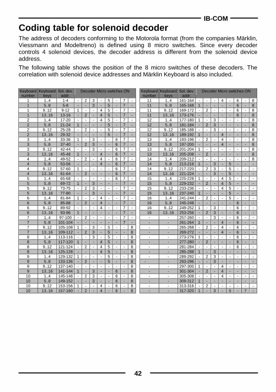
Coding table for solenoid decoder The address of decoders conforming to the Motorola format (from the companies Märklin, Viessmann and Modeltreno) is defined using 8 micro switches. Since every decoder controls 4 solenoid devices, the decoder address is different from the solenoid device address. The following table shows the position of the 8 micro switches of these decoders. The correlation with solenoid device addresses and Märklin Keyboard is also included.
Keyboard number
Keyboard keys
Sol. dev. addr.
Decoder Micro switches ON
1 1..4 1-4 - 2 3 - 5 - 7 - 1 5..8 5-8 - - 3 - 5 - 7 - 1 9..12 9-12 1 - - 4 5 - 7 - 1 13..16 13-16 - 2 - 4 5 - 7 - 2 1..4 17-20 - - - 4 5 - 7 - 2 5..8 21-24 1 - - - 5 - 7 - 2 9..12 25-28 - 2 - - 5 - 7 - 2 13..16 29-32 - - - - 5 - 7 - 3 1..4 33-36 1 - 3 - - 6 7 - 3 5..8 37-40 - 2 3 - - 6 7 - 3 9..12 42-44 - - 3 - - 6 7 - 3 13..16 45-48 1 - - 4 - 6 7 - 4 1..4 49-52 - 2 - 4 - 6 7 - 4 5..8 53-56 - - - 4 - 6 7 - 4 9..12 57-60 1 - - - - 6 7 - 4 13..16 61-64 - 2 - - - 6 7 - 5 1..4 65-68 - - - - - 6 7 - 5 5..8 69-72 1 - 3 - - - 7 - 5 9..12 73-75 - 2 3 - - - 7 - 5 13..16 77-80 - - 3 - - - 7 - 6 1..4 81-84 1 - - 4 - - 7 - 6 5..8 85-88 - 2 - 4 - - 7 - 6 9..12 89-92 - - - 4 - - 7 - 6 13..16 93-96 1 - - - - - 7 - 7 1..4 97-100 - 2 - - - - 7 - 7 5..8 101-104 - - - - - - 7 - 7 9..12 105-108 1 - 3 - 5 - - 8 7 13..16 109-112 - 2 3 - 5 - - 8 8 1..4 113-116 - - 3 - 5 - - 8 8 5..8 117-120 1 - - 4 5 - - 8 8 9..12 121-124 - 2 - 4 5 - - 8 8 13..16 125-128 - - - 4 5 - - 8 9 1..4 129-132 1 - - - 5 - - 8 9 5..8 133-136 - 2 - - 5 - - 8 9 9..12 137-140 - - - - - - - 8 9 13..16 141-144 1 - 3 - - 6 - 8
10 1..4 145-148 - 2 3 - - 6 - 8 10 5..8 149-152 - - 3 - - 6 - 8 10 9..12 153-156 1 - - 4 - 6 - 8 10 13..16 157-160 - 2 - 4 - 6 - 8
Keyboard number
Keyboardkeys
Sol. dev.addr.
Decoder Micro switches ON
11 1..4 161-164 - - - 4 - 6 - 8 11 5..8 165-168 1 - - - - 6 - 8 11 9..12 169-172 - 2 - - - 6 - 8 11 13..16 173-176 - - - - - 6 - 8 12 1..4 177-180 1 - 3 - - - - 8 12 5..8 181-184 - 2 3 - - - - 8 12 9..12 185-188 - - 3 - - - - 8 12 13..16 189-192 1 - - 4 - - - 8 13 1..4 193-196 - 2 - 4 - - - 8 13 5..8 197-200 - - - 4 - - - 8 13 9..12 201-204 1 - - - - - - 8 13 13..16 205-208 - 2 - - - - - 8 14 1..4 209-212 - - - - - - - 8 14 5..8 213-216 1 - 3 - 5 - - - 14 9..12 217-220 - 2 3 - 5 - - - 14 13..16 221-224 - - 3 - 5 - - - 15 1..4 225-228 1 - - 4 5 - - - 15 5..8 229-232 - 2 - 4 5 - - - 15 9..12 233-236 - - - 4 5 - - - 15 13..16 237-240 1 - - - 5 - - - 16 1..4 241-244 - 2 - - 5 - - - 16 5..8 245-248 - - - - - 6 - - 16 9..12 249-252 1 - 3 - - 6 - - 16 13..16 253-256 - 2 3 - - 6 - - - - 257-260 - - 3 - - 6 - - - - 261-264 1 - - 4 - 6 - - - - 265-268 - 2 - 4 - 6 - - - - 269-272 - - - 4 - 6 - - - - 273-276 1 - - - - 6 - - - - 277-280 - 2 - - - 6 - - - - 281-284 - - - - - 6 - - - - 285-288 1 - 3 - - - - - - - 289-292 - 2 3 - - - - -
- - 293-296 - - 3 - - - - - - - 297-300 1 - - 4 - - - - - - 301-304 - 2 - 4 - - - - - - 305-308 - - - 4 - - - - - - 309-312 1 - - - - - - - - - 313-316 - 2 - - - - - - - - 317-320 1 - 3 - 5 - 7 -
IB-COM
43
Tips and Tricks Some Märklin locomotives can’t be controlled Older Märklin decoders (6080 and Delta decoders) can only be controlled with the IB-COM if the red wire from the centre pick up is connected to the rail.
Old and new Märklin function decoders The Panorama car and the Märklin Digital remote control rotary crane (7051+7652), are controlled with the old Motorola protocol, using f1-f4 functions. They are not able to operate with the new Märklin-Motorola protocol. New Märklin locomotives (with smoke, sound effects, etc), new Märklin decoders (60901, etc.) and Uhlenbrock decoders (755, 756, 760 in operating mode 1-3) operate only in the new protocol, and ignore the f1-f4 function signals of the old protocol.
Problems controlling the lights in DCC decoders If the locomotive lights no longer respond to the [function] key, it’s most likely that the decoder is configured for 28 operating levels while the IB-COM expect 14/27 speed levels for that locomotive address. To solve this situation, change (in the IB-COM) the configuration of the relevant decoder address to 28 operating levels. Remember that NMRA standards impose the following specifications for CV #29:
14 operating levels CV#29 Bit 1 = 0 28 operating levels CV#29 Bit 1 = 1 128 operating levels CV#29 Bit 1 = 1
Problems of DCC Decoders with other Data formats Some DCC decoders have problems running cleanly if decoders using different data formats are on the rails as well. These decoders falsely interpret the Motorola data signal as analog voltage and will "stutter" when driving or suddenly drive off with full speed. With some decoders this behavior can be eliminated by switching off the automatic recognition of the analog operation. How the decoder is configured to pure digital operation can be found in the operating instructions for the appropriate decoder. With some newer decoder types programming to pure digital operation is done by setting bit 2 of the configuration variable CV 29 to zero. Note however that is not possible with all DCC decoders. With simple decoders there is no possibility of eliminating this problem.
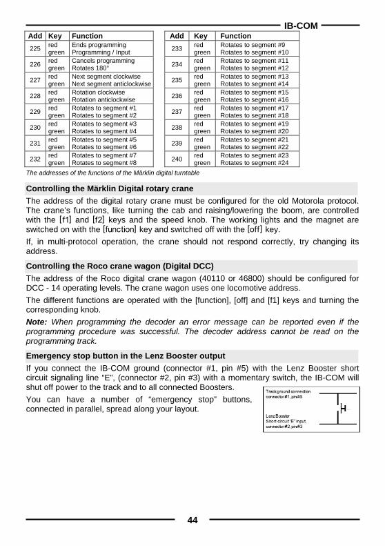
Controlling the Märklin Digital turntable The turntable can be retrofitted with a specific decoder (7687) compatible with the Motorola protocol. The different functions respond to the solenoid devices addresses 225 to 240. Attention! The Märklin turntable decoder can only be put into programming mode within the first 5 seconds of switching on of the operating voltage. The IB-COM needs approx. 13 seconds to boot up. Subsequently the decoder will not accept any further instructions, if IB-COM and turntable are switched on at the same time. We recommend installing a switch in the yellow and red wires to the turntable decoder. The switch remains open until the IB-COM has completed its boot up. Then it is closed and the programming process can begin, as in the operating instructions of the turntable described.
IB-COM
44
Add Key Function Add Key Function 225 red
green Ends programming Programming / Input
233 red green
Rotates to segment #9 Rotates to segment #10
226 red green
Cancels programming Rotates 180°
234 red green
Rotates to segment #11 Rotates to segment #12
227 red green
Next segment clockwise Next segment anticlockwise
235 red green
Rotates to segment #13 Rotates to segment #14
228 red green
Rotation clockwise Rotation anticlockwise
236 red green
Rotates to segment #15 Rotates to segment #16
229 red green
Rotates to segment #1 Rotates to segment #2
237 red green
Rotates to segment #17 Rotates to segment #18
230 red green
Rotates to segment #3 Rotates to segment #4
238 red green
Rotates to segment #19 Rotates to segment #20
231 red green
Rotates to segment #5 Rotates to segment #6
239 red green
Rotates to segment #21 Rotates to segment #22
232 red green
Rotates to segment #7 Rotates to segment #8
240 red green
Rotates to segment #23 Rotates to segment #24
The addresses of the functions of the Märklin digital turntable
Controlling the Märklin Digital rotary crane The address of the digital rotary crane must be configured for the old Motorola protocol. The crane’s functions, like turning the cab and raising/lowering the boom, are controlled with the : and ; keys and the speed knob. The working lights and the magnet are switched on with the f key and switched off with the o key. If, in multi-protocol operation, the crane should not respond correctly, try changing its address.
Controlling the Roco crane wagon (Digital DCC) The address of the Roco digital crane wagon (40110 or 46800) should be configured for DCC - 14 operating levels. The crane wagon uses one locomotive address. The different functions are operated with the [function], [off] and [f1] keys and turning the corresponding knob. Note: When programming the decoder an error message can be reported even if the programming procedure was successful. The decoder address cannot be read on the programming track.
Emergency stop button in the Lenz Booster output If you connect the IB-COM ground (connector #1, pin #5) with the Lenz Booster short circuit signaling line “E”, (connector #2, pin #3) with a momentary switch, the IB-COM will shut off power to the track and to all connected Boosters. You can have a number of “emergency stop” buttons, connected in parallel, spread along your layout.
IB-COM
45
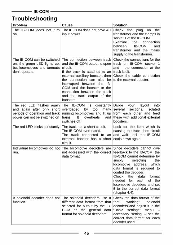
Troubleshooting Problem Cause Solution The IB-COM does not turn on.
The IB-COM does not have AC input power.
Check the plug on the transformer and the clamps in socket 1 of the IB-COM. Examine the connection between IB-COM and transformer and the mains supply to the transformer.
The IB-COM can be switched on, the green LED lights up, but locomotives and turnouts don’t operate.
The connection between track and the IB-COM output is open circuit. If the track is attached to an external auxiliary booster, then the connection can also be interrupted between the IB-COM and the booster or the connection between the track and the track output of the boosters.
Check the connections for the track on IB-COM socket 1 and the connection at the track itself. Check the cable connection to the external booster.
The red LED flashes again and again after only short periods of operation and track power can not be switched on
The IB-COM is constantly overloaded by too many running locomotives and lit up trains. It overheats and switches off.
Divide your layout into several sections, isolated from each other and feed these with additional external boosters.
The red LED blinks constantly The track has a short circuit. The IB-COM overheated. The track connected to an external booster has a short circuit.
Look for the item which is causing the track short circuit and wait until the IB-COM cools down again.
Individual locomotives do not run.
The locomotive decoders are not addressed with the correct data format.
Since decoders cannot give feedback to the IB-COM, the IB-COM cannot determine by simply selecting the locomotive address, which data format is required to control the decoder. Check the data format needed for each of the locomotive decoders and set it to the correct data format (chapter 4.4).
A solenoid decoder does not function.
The solenoid decoders use a different data format from that selected for output by the IB-COM as the general data format for solenoid decoders.
Check the data format of the “not working” solenoid decoders and adjust it in the “Basic settings” menu – accessory setting – set the correct data format for each decoder used.

IB-COM
46
HOTLINE
When you are at a loss on how to continue
We are here for you. Mondays to Fridays 14:00-16:00
Wednesdays 16:00-18:00
02045-858327
Before you call us, Make sure you have the following at hand:
Serial number of your IB-COM, version number of the system software
and this manual.
You can obtain our catalog from your specialist dealer or from us for 3.50 euro plus postage of 5.00 euro in stamps.
All our products have a warranty of two years. We reserve the right to change data in this booklet at anytime.
Authors: Dr.-Ing. T. Vaupel, D. Richter, M. Berger Translated by Wolfram Steinke
© Copyright Uhlenbrock Elektronik GmbH, Bottrop 1st Edition November 2009
Starting from Software version 1.0 All Rights Reserved
Duplication is only allowed with written Authorization


![mohp.gov.npmohp.gov.np/downloads/शिशु तथा... · 2019. 9. 28. · ;d'bfo :t/Lo tflnd lgb]{lzsf tflnd lgb{]lzsfsf] kl/ro s_ tflnd lgb]{lzsfsf] kl/ro dlxnf / afnaflnsfx?sf]](https://img.pdfslide.net/doc/110x75/60ff81be87b501220c61ceba/mohpgov-aaa-aaa-2019-9-28-dbfo-tlo-tflnd-lgblzsf.jpg)


![PsLs[t lgb]{zg, @)&&](https://img.pdfslide.net/doc/110x75/62bbe2f8f90bfa25b433423c/pslst-lgbzg-ampamp.jpg)


![:jf:Yo tfnLd Joj:yfkg lgb]{lzsf](https://img.pdfslide.net/doc/110x75/62897c50bed6667d184c5aa4/jfyo-tfnld-jojyfkg-lgblzsf.jpg)


