Embed Size (px)
Citation preview
GEInspection Technologies Ultrasonics
Digital | Eddy Current | Film | Testing Machines | Ultrasonics | X-ray
GEInspectionTechnologies.com
Krautkramer USN 60Operating Manual
g©2013 General Electric Company. All rights reserved.
We reserve the right to technical modifications without prior notice

USN 60Technical Handbook and Operating Manual
Id. No. 28 691021-002-178 Rev AF
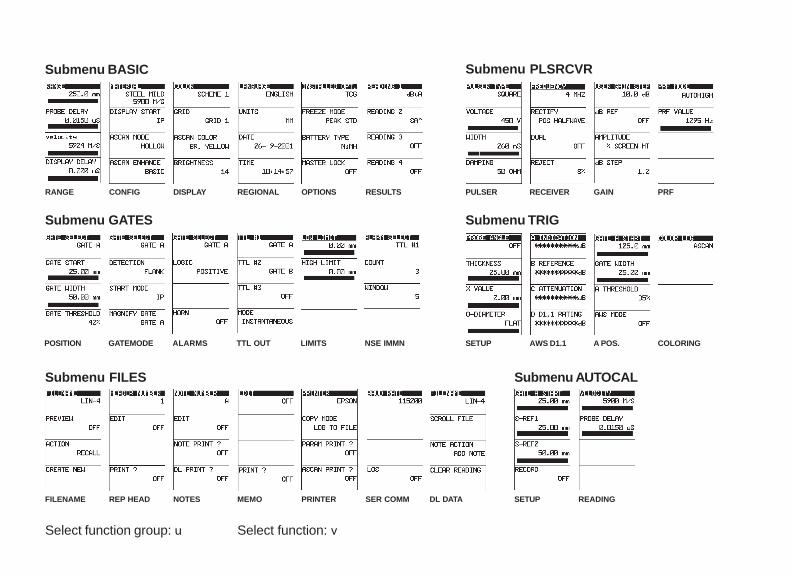
Submenu BASIC Submenu PLSRCVR
PULSER RECEIVER GAIN PRF
SETUP AWS D1.1 A POS. COLORING
SETUP READING
Select function group: u Select function: v
Submenu GATES
Submenu FILES
POSITION GATEMODE ALARMS TTL OUT LIMITS NSE IMMN
FILENAME REP HEAD NOTES MEMO PRINTER SER COMM DL DATA
Submenu TRIG
Submenu AUTOCAL
RANGE CONFIG DISPLAY REGIONAL OPTIONS RESULTS
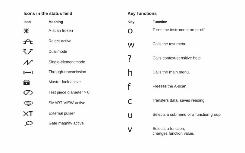
Icons in the status field
Icon Meaning
A-scan frozen
Reject active
Dual mode
Single-element mode
Through-transmission
Master lock active
Test piece diameter > 0
SMART VIEW active
External pulser
Gate magnify active
Key functions
Key Function
o Turns the instrument on or off.
w Calls the test menu.
? Calls context-sensitive help.
h Calls the main menu.
f Freezes the A-scan.
c Transfers data, saves reading.
u Selects a submenu or a function group.
v Selects a function,changes function value.
Krautkramer USN 60 Issue AF, 03/2013 0-1
Content
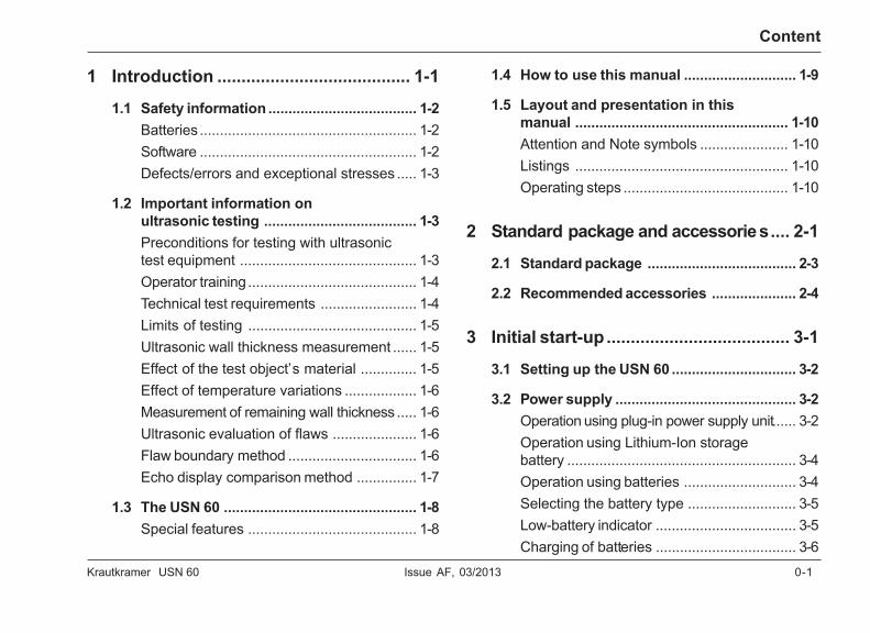
1 Introduction ........................................ 1-1
1.1 Safety information ..................................... 1-2Batteries ...................................................... 1-2Software ...................................................... 1-2Defects/errors and exceptional stresses ..... 1-3
1.2 Important information onultrasonic testing ...................................... 1-3Preconditions for testing with ultrasonictest equipment ............................................ 1-3Operator training .......................................... 1-4Technical test requirements ........................ 1-4Limits of testing .......................................... 1-5Ultrasonic wall thickness measurement ...... 1-5Effect of the test object’s material .............. 1-5Effect of temperature variations .................. 1-6Measurement of remaining wall thickness ..... 1-6Ultrasonic evaluation of flaws ..................... 1-6Flaw boundary method ................................ 1-6Echo display comparison method ............... 1-7
1.3 The USN 60 ................................................ 1-8Special features .......................................... 1-8
1.4 How to use this manual ............................ 1-9
1.5 Layout and presentation in thismanual ..................................................... 1-10Attention and Note symbols ...................... 1-10Listings ..................................................... 1-10Operating steps ......................................... 1-10
2 Standard package and accessories.... 2-1
2.1 Standard package ..................................... 2-3
2.2 Recommended accessories ..................... 2-4
3 Initial start-up...................................... 3-1
3.1 Setting up the USN 60 ............................... 3-2
3.2 Power supply ............................................. 3-2Operation using plug-in power supply unit...... 3-2Operation using Lithium-Ion storagebattery ......................................................... 3-4Operation using batteries ............................ 3-4Selecting the battery type ........................... 3-5Low-battery indicator ................................... 3-5Charging of batteries ................................... 3-6
0-2 Issue AF, 03/2013 Krautkramer USN 60
Content
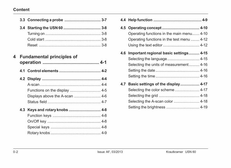
3.3 Connecting a probe .................................. 3-7
3.4 Starting the USN 60 ................................... 3-8Turning on .................................................... 3-8Cold start .................................................... 3-8Reset .......................................................... 3-8
4 Fundamental principles ofoperation ............................................ 4-1
4.1 Control elements ....................................... 4-2
4.2 Display ....................................................... 4-4A-scan......................................................... 4-4Functions on the display ............................. 4-5Displays above the A-scan ......................... 4-6Status field .................................................. 4-7
4.3 Keys and rotary knobs .............................. 4-8Function keys ............................................. 4-8On/Off key .................................................. 4-8Special keys ............................................... 4-8Rotary knobs ............................................... 4-9
4.4 Help function ............................................. 4-9
4.5 Operating concept ................................... 4-10Operating functions in the main menu....... 4-10Operating functions in the test menu ........ 4-12Using the text editor .................................. 4-12
4.6 Important regional basic settings.......... 4-15Selecting the language.............................. 4-15Selecting the units of measurement.......... 4-16Setting the date ......................................... 4-16Setting the time ......................................... 4-16
4.7 Basic settings of the display.................. 4-17Selecting the color scheme ....................... 4-17Selecting the grid ...................................... 4-18Selecting the A-scan color ........................ 4-18Setting the brightness ............................... 4-19
Krautkramer USN 60 Issue AF, 03/2013 0-3
Content
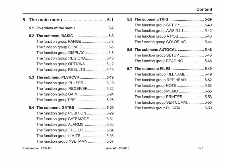
5 The main menu .................................. 5-1
5.1 Overview of the menu ............................... 5-2
5.2 The submenu BASIC................................. 5-3The function group RANGE ......................... 5-3The function group CONFIG........................ 5-6The function group DISPLAY ...................... 5-8The function group REGIONAL................. 5-10The function group OPTIONS ................... 5-12The function group RESULTS ................... 5-16
5.3 The submenu PLSRCVR......................... 5-19The function group PULSER..................... 5-19The function group RECEIVER................. 5-22The function group GAIN .......................... 5-24The function group PRF ............................ 5-26
5.4 The submenu GATES ............................. 5-29The function group POSITION .................. 5-29The function group GATEMODE ............... 5-31The function group ALARMS .................... 5-33The function group TTL OUT ..................... 5-34The function group LIMITS ....................... 5-36The function group NSE IMMN ................. 5-37
5.5 The submenu TRIG ................................. 5-39The function group SETUP ....................... 5-40The function group AWS D1.1 ................... 5-42The function group A POS. ....................... 5-43The function group COLORING................. 5-44
5.6 The submenu AUTOCAL ......................... 5-46The function group SETUP ....................... 5-46The function group READING ................... 5-48
5.7 The submenu FILES ............................... 5-49The function group FILENAME ................. 5-49The function group REP HEAD................. 5-52The function group NOTE .......................... 5-53The function group MEMO ........................ 5-55The function group PRINTER .................... 5-56The function group SER COMM................ 5-58The function group DL DATA...................... 5-59
0-4 Issue AF, 03/2013 Krautkramer USN 60
Content
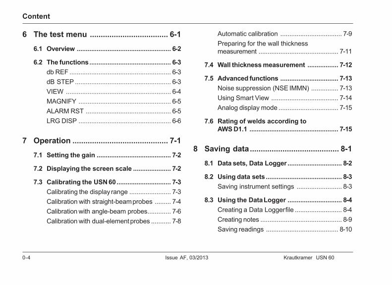
6 The test menu .................................... 6-1
6.1 Overview .................................................... 6-2
6.2 The functions............................................. 6-3db REF ........................................................ 6-3dB STEP ..................................................... 6-3VIEW .......................................................... 6-4MAGNIFY ................................................... 6-5ALARM RST ............................................... 6-5LRG DISP ................................................... 6-6
7 Operation ............................................ 7-1
7.1 Setting the gain ......................................... 7-2
7.2 Displaying the screen scale ..................... 7-2
7.3 Calibrating the USN 60.............................. 7-3Calibrating the display range ....................... 7-3Calibration with straight-beam probes ......... 7-4Calibration with angle-beam probes............. 7-6Calibration with dual-element probes ........... 7-8
Automatic calibration .................................. 7-9Preparing for the wall thicknessmeasurement ............................................ 7-11
7.4 Wall thickness measurement ................. 7-12
7.5 Advanced functions ................................ 7-13Noise suppression (NSE IMMN) ............... 7-13Using Smart View ..................................... 7-14Analog display mode ................................. 7-15
7.6 Rating of welds according toAWS D1.1 ................................................. 7-15
8 Saving data......................................... 8-1
8.1 Data sets, Data Logger .............................. 8-2
8.2 Using data sets .......................................... 8-3Saving instrument settings ......................... 8-3
8.3 Using the Data Logger .............................. 8-4Creating a Data Logger file .......................... 8-4Creating notes ............................................. 8-9Saving readings ........................................ 8-10
Krautkramer USN 60 Issue AF, 03/2013 0-5
Content
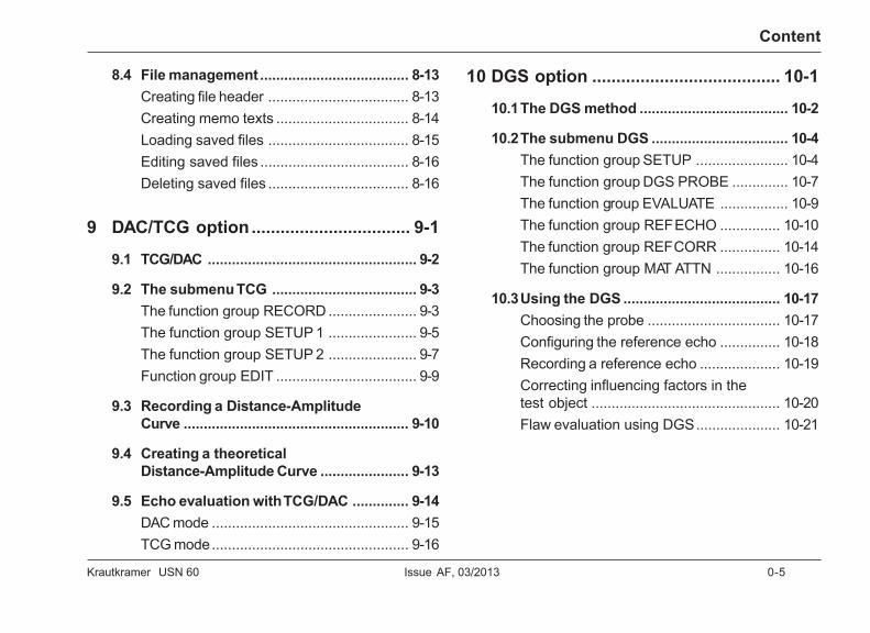
8.4 File management ..................................... 8-13Creating file header ................................... 8-13Creating memo texts ................................. 8-14Loading saved files ................................... 8-15Editing saved files ..................................... 8-16Deleting saved files ................................... 8-16
9 DAC/TCG option................................. 9-1
9.1 TCG/DAC .................................................... 9-2
9.2 The submenu TCG .................................... 9-3The function group RECORD ...................... 9-3The function group SETUP 1 ...................... 9-5The function group SETUP 2 ...................... 9-7Function group EDIT ................................... 9-9
9.3 Recording a Distance-AmplitudeCurve ........................................................ 9-10
9.4 Creating a theoreticalDistance-Amplitude Curve ...................... 9-13
9.5 Echo evaluation with TCG/DAC .............. 9-14DAC mode ................................................. 9-15TCG mode................................................. 9-16
10 DGS option ....................................... 10-1
10.1The DGS method ..................................... 10-2
10.2The submenu DGS .................................. 10-4The function group SETUP ....................... 10-4The function group DGS PROBE .............. 10-7The function group EVALUATE ................. 10-9The function group REF ECHO ............... 10-10The function group REF CORR ............... 10-14The function group MAT ATTN ................ 10-16
10.3Using the DGS ....................................... 10-17Choosing the probe ................................. 10-17Configuring the reference echo ............... 10-18Recording a reference echo .................... 10-19Correcting influencing factors in thetest object ............................................... 10-20Flaw evaluation using DGS..................... 10-21

0-6 Issue AF, 03/2013 Krautkramer USN 60
Content
11 Interface echo gate option .............. 11-1
11.1The interface echo gate .......................... 11-2
11.2The submenu GATES ............................. 11-2The function group IF ADV ........................ 11-3
11.3Using the interface echo gate................. 11-5Setting up the interface echo gate ............ 11-5Defining interface echo gate as displayzero ........................................................... 11-6Automatic gate tracking ............................ 11-7Additional measured values ...................... 11-7
11.4Immersion testing ................................... 11-8
12 Backwall Echo Attenuationoption ................................................ 12-1
12.1Backwall Echo Attenuation .................... 12-2
12.2The submenu PLSRCVR......................... 12-3The function group BCK ATTN. ................. 12-3
12.3Using the Backwall Echo Attenuation .... 12-6
13 Documentation ................................ 13-1
13.1Printing a report ...................................... 13-2Preparing for printing ................................. 13-3Configuring the c key .......................... 13-3Printing ...................................................... 13-3
14 Care and maintenance .................... 14-1
14.1Care of the instrument ............................ 14-2
14.2Maintaining batteries .............................. 14-2Charging the Lithium-Ion storage battery .... 14-2Charging NiMH storage batteries .............. 14-3Care of NiMH batteries .............................. 14-3How to handle alkaline batteries................ 14-4
14.3Maintenance ............................................ 14-4
Krautkramer USN 60 Issue AF, 03/2013 0-7
Content
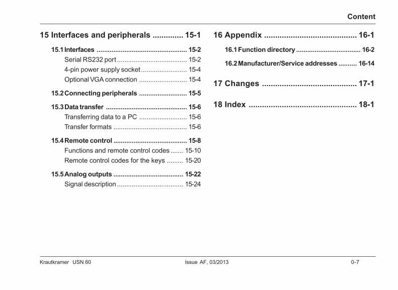
15 Interfaces and peripherals .............. 15-1
15.1Interfaces ................................................. 15-2Serial RS232 port ...................................... 15-24-pin power supply socket ......................... 15-4Optional VGA connection .......................... 15-4
15.2Connecting peripherals .......................... 15-5
15.3Data transfer ............................................ 15-6Transferring data to a PC .......................... 15-6Transfer formats ........................................ 15-6
15.4Remote control ........................................ 15-8Functions and remote control codes ....... 15-10Remote control codes for the keys ......... 15-20
15.5Analog outputs ...................................... 15-22Signal description .................................... 15-24
16 Appendix .......................................... 16-1
16.1Function directory ................................... 16-2
16.2Manufacturer/Service addresses .......... 16-14
17 Changes ........................................... 17-1
18 Index ................................................. 18-1

0-8 Issue AF, 03/2013 Krautkramer USN 60
Krautkramer USN 60 Issue AF, 03/2013 1-1
Introduction 1
1-2 Issue AF, 03/2013 Krautkramer USN 60
Introduction
1.1 Safety information
The USN 60 is designed and tested according toEN 12668-1: 2010, “Non-destructive testing, character-ization and verification of ultrasonic examination equip-ment – Part 1 – Instruments.” and was technically inperfectly safe and faultless condition when leaving themanufacturing works.
In order to maintain this condition and to ensure a safeoperation, it is absolutely necessary that you read thefollowing safety information before putting the instru-ment into operation.
A Attention:
The USN 60 is an instrument for materials testing.Any use for medical applications or other purposesis not allowed!
The instrument may only be used in industrialenvironments.
BatteriesThe USN 60 can be operated using alkaline batteries,NiMH, NiCad storage batteries, the Lithium-Ion storagebattery LIA 60, or a power supply unit. For mobile op-eration, we recommend the use of Lithium-Ion storagebattery that has a maximum capacity and therefore en-sures a long operating time.
Standard storage batteries (NiMH or NiCad) must becharged in an external battery charger. You can chargethe Lithium-Ion storage battery during operation directlyon the USN 60 using the external power supply/chargerunit UN 670.
As soon as you connect the power supply unit (plug-inpower supply unit) to the USN 60, the power supply tothe battery compartment is interrupted. Please readchapter 14 Care and Maintenance to learn mhow to usestorage batteries.
SoftwareAccording to the current state of the art, software isnever completely free from errors.
Before using any software-controlled test equipment,please make sure that the required functions operateperfectly in the intended combination.
Safety information
Krautkramer USN 60 Issue AF, 03/2013 1-3
Introduction
If you have any questions about the use of yourKrautkramer test equipment, please contact yournearest representative of GE Inspection Technologies.
Defects/errors and exceptional stressesIf you have reason to believe that a safe operation ofyour USN 60 is no longer possible, you have to discon-nect the instrument and secure it against unintentionalreconnection. Remove the batteries if necessary.
A safe operation is e.g. no longer possible
• if the instrument shows visible damages,
• if the instrument no longer operates perfectly,
• after prolonged storage under adverse conditions(e.g. exceptional temperatures and/or especially highair humidity, or corrosive environmental conditions),
• after being subjected to heavy stresses duringtransportation.
Safety information
1.2 Important information onultrasonic testing
Please read the following information before using yourUSN 60. It is important that you understand and ob-serve this information to avoid any operator errors thatmight lead to false test results. This could result in per-sonal injuries or damages to property.
Preconditions for testing with ultrasonictest equipmentThis operating manual contains essential informationon how to operate your test equipment. In addition,there are a number of factors which affect the test re-sults. A description of these factors would go beyondthe scope of an operating manual. The following listtherefore only mentions the three most important con-ditions for a safe and reliable ultrasonic inspection:
• the operator training,
• the knowledge of special technical test requirementsand limits,
• the choice of appropriate test equipment.
1-4 Issue AF, 03/2013 Krautkramer USN 60
Introduction
Operator trainingThe operation of an ultrasonic test device requires aproper training in ultrasonic test methods.
A proper training comprises for example adequateknowledge of:
• the theory of sound propagation,
• the effects of sound velocity in the test material,
• the behavior of the sound wave at interfaces be-tween different materials,
• the propagation of the sound beam,
• the influence of sound attenuation in the test objectand the influence of surface quality of the testobject.
Lack of such knowledge could lead to false test resultswith unforeseeable consequences. You can contact forexample NDT societies or organizations in your coun-try (DGZfP in Germany; ASNT in the USA), or also GEInspection Technologies, for information concerning ex-isting possibilities for the training of ultrasonic inspec-tors as well as on the qualifications and certificatesthat can finally be obtained.
Important information on ultrasonic testing
Technical test requirementsEvery ultrasonic test is subject to specific technicaltest requirements. The most important ones are:
• the definition of the scope of inspection,
• the choice of the appropriate test method,
• the consideration of material properties,
• the determination of limits for recording and evalua-tion.
It is the task of those with overall responsibility fortesting to ensure that the inspector is fully informedabout these requirements. The best basis for such in-formation is experience with identical test objects. It isalso essential that the relevant test specifications beclearly and completely understood by the inspector. GEInspection Technologies regularly holds specializedtraining courses in the field of ultrasonic testing.
The scheduled dates for these courses will be given toyou on request.
Krautkramer USN 60 Issue AF, 03/2013 1-5
IntroductionImportant information on ultrasonic testing
Limits of testingThe information obtained from ultrasonic tests only re-fers to those parts of the test object which are coveredby the sound beam of the probe used.
Any conclusions from the tested parts to be applied tothe untested parts of the test object should be madewith extreme caution.
Such conclusions are generally only possible in caseswhere extensive experience and proven methods ofstatistical data acquisition are available.
The sound beam can be completely reflected fromboundary surfaces within the test object so that flawsand reflection points lying deeper remain undetected. Itis therefore important to make sure that all areas to betested in the test object are covered by the soundbeam.
Ultrasonic wall thickness measurementAll ultrasonic wall thickness measurements are basedon a time-of-flight measurement. Accurate measure-ment results require a constant sound velocity in thetest object. In test objects made of steel, even withvarying alloying constituents, this condition is mostlyfulfilled. The variation in sound velocity is so slight thatit is only of importance for high-precision measure-ments. In other materials, e.g. nonferrous metals orplastics, the sound velocity variations may be evenlarger and thus affect the measuring accuracy.
Effect of the test object’s materialIf the test object’s material is not homogeneous, thesound may propagate at different sound velocities indifferent parts of the test objects. An average soundvelocity should then be taken into account for therange calibration. This is achieved by means of a refer-ence block whose sound velocity corresponds to theaverage sound velocity of the test object.
If substantial sound velocity variations are to be ex-pected, then the instrument calibration should be read-justed to the actual sound velocity values at shortertime intervals. Failure to do so may lead to false thick-ness readings.
1-6 Issue AF, 03/2013 Krautkramer USN 60
Introduction Important information on ultrasonic testing
Effect of temperature variationsThe sound velocity within the test object also varies asa function of the material’s temperature. This cancause appreciable errors in measurements if the instru-ment has been calibrated on a cold reference blockand is then used on a warm or hot test object. Suchmeasurement errors can be avoided either by warmingthe reference block to the same temperature beforecalibrating, or by using a correction factor obtainedfrom tables.
Measurement of remaining wall thicknessThe measurement of the remaining wall thickness onplant components, e.g. pipes, tanks and reaction ves-sels of all types which are corroded or eroded from theinside, requires a perfectly suitable gauge and specialcare in handling the probe.
The inspectors should always be informed about thecorresponding nominal wall thicknesses and the likelyamount of wall thickness losses.
Ultrasonic evaluation of flawsIn present-day test practice, there are basically two dif-ferent methods of flaw evaluation:
If the diameter of the sound beam is smaller than theextent of the flaw, then the beam can be used to ex-plore the boundaries of the flaw and thus determine itsarea.
If, however, the diameter of the sound beam is largerthan the size of the flaw, the maximum echo responsefrom the flaw must be compared with the maximumecho response from an artificial flaw provided for com-parison purposes.
Flaw boundary methodThe smaller the diameter of the probe’s sound beam,the more accurately the boundaries (and therefore theflaw area) can be determined by the flaw boundarymethod. If, however, the sound beam is relativelybroad, the flaw area determined can substantially differfrom the actual flaw area. Care should therefore betaken to select a probe which will give a sufficientlynarrow beam at the position of the flaw.
Krautkramer USN 60 Issue AF, 03/2013 1-7
IntroductionImportant information on ultrasonic testing
Echo display comparison methodThe echo from a small, natural flaw is usually smallerthan the echo from an artificial comparison flaw, e.g.circular disc flaw of the same size. This is due, for in-stance, to the roughness of the surface of a naturalflaw, or to the fact that the beam does not impinge onit at right angles.
If this fact is not taken into account when evaluatingnatural flaws, there is a danger of underestimating theirmagnitude.
In the case of very jagged or fissured flaws, e.g. shrinkholes in castings, it may be that the sound scatteringoccurring at the boundary surface of the flaw is sostrong that no echo at all is produced. In such cases, adifferent evaluation method should be chosen, e.g. useof the backwall echo attenuation in the evaluation.
The distance sensitivity of the flaw echo plays an im-portant part when testing large components. Attentionshould be paid here to choosing artificial comparisonflaws which are as far as possible governed by thesame “distance laws” as the natural flaws to be evalu-ated.
The ultrasonic wave is attenuated in any material. Thissound attenuation is very low, e.g. in parts made offine-grained steel, likewise in many small parts madeof other materials. However, if the sound wave travelslarger distances through the material, a high cumula-tive sound attenuation can result even with small at-tenuation coefficients. There is then a danger that ech-oes from natural flaws appear too small. For thisreason, an estimate must always be made of the ef-fects of attenuation on the evaluation result and takeninto account if applicable.
If the test object has a rough surface, part of the inci-dent sound energy will be scattered at its surface andis not available for the test. The larger this initial scat-tering, the smaller the flaw echoes appear, and themore errors occur in the evaluation result.
It is therefore important to take the effect of the testobject’s surfaces on the height of the echo into ac-count (transfer correction).
1-8 Issue AF, 03/2013 Krautkramer USN 60
Introduction The USN 60
1.3 The USN 60
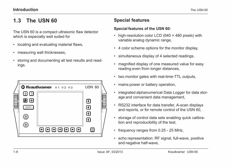
The USN 60 is a compact ultrasonic flaw detectorwhich is especially well suited for
• locating and evaluating material flaws,
• measuring wall thicknesses,
• storing and documenting all test results and read-ings.
Special features
Special features of the USN 60:
• high-resolution color LCD (640 × 480 pixels) withvariable analog dynamic range,
• 4 color scheme options for the monitor display,
• simultaneous display of 4 selected readings,
• magnified display of one measured value for easyreading even from longer distances,
• two monitor gates with real-time-TTL outputs,
• mains power or battery operation,
• integrated alphanumerical Data Logger for data stor-age and convenient data management,
• RS232 interface for data transfer, A-scan displaysand reports, or for remote control of the USN 60,
• storage of control data sets enabling quick calibra-tion and reproducibility of the test,
• frequency ranges from 0.25 - 25 MHz,
• echo representation: RF signal, full-wave, positiveand negative half-wave,
Krautkramer USN 60 Issue AF, 03/2013 1-9
IntroductionThe USN 60
• optimized probe matching by means of 4 adjustabledamping values between 50 and 500 ohms,
• automatic calibration of the sound velocity andprobe delay according to data from 2 calibrationechoes (with plausibility check),
• freely adjustable pulse repetition frequency to avoidphantom echoes,
• indication of amplitude and sound path for flawtesting and thickness measurement,
• analog outputs for external control purposes: propor-tional voltage for amplitude and sound path of theecho in the monitor gate,
• A-scan freeze mode, recording of peak amplitude,A-scan persistence in 3 steps,
• preview of all stored A-Scans and readings,
• locking function to avoid unintentional alteration ofset values,
• context-sensitive help on all functions,
• an easy-to-clean keypad.
1.4 How to use this manual
Before operating the USN 60 for the first time, it is ab-solutely necessary that you read the chapters 1, 3 and4 of this manual. They will inform you about the neces-sary preparations of the instrument, give you a descrip-tion of all keys and screen displays, and explain theoperating principle.
In doing this, you will avoid any errors or failures of theinstrument and be able to use the full range of instru-ment functions.
You will find the latest changes to this operatingmanual in chapter 17 Changes. It describes correctionsthat have become necessary at short notice and havenot yet been included in the general manual. If no cor-rections have become necessary, this chapter isempty.
To make it easier for you to use this manual, all operat-ing steps, notes, etc., are always presented in thesame way. This will help you find individual pieces ofinformation quickly.
1-10 Issue AF, 03/2013 Krautkramer USN 60
Introduction Layout and presentation in this manual
1.5 Layout and presentation inthis manual
Attention and Note symbols
A Attention:
The Attention symbol indicates peculiarities and spe-cial aspects in the operation which could affect the ac-curacy of the results.
H Note:
Note contains e.g. references to other chapters or spe-cial recommendations for a function.
ListingsListings are presented in the following form:
• Variant A
• Variant B
• ...
Operating stepsOperating steps appear as shown in the following ex-ample:
– Select the function VELOCITY.
– If necessary, use the v key to toggle betweencoarse and fine setting.
– ...
Krautkramer USN 60 Issue AF, 03/2013 2-1
Standard package and accessories 2
2-2 Issue AF, 03/2013 Krautkramer USN 60
Standard package and accessories
This chapter informs you about the standard package and the accessories available for the USN 60.
It describes
• accessories included in the standard package,
• recommended accessories.
Krautkramer USN 60 Issue AF, 03/2013 2-3
Standard package and accessoriesStandard package
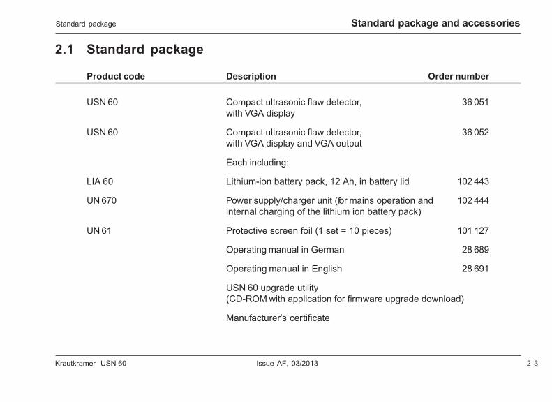
2.1 Standard package
Product code Description Order number
USN 60 Compact ultrasonic flaw detector, 36 051with VGA display
USN 60 Compact ultrasonic flaw detector, 36 052with VGA display and VGA output
Each including:
LIA 60 Lithium-ion battery pack, 12 Ah, in battery lid 102 443
UN 670 Power supply/charger unit (for mains operation and 102 444internal charging of the lithium ion battery pack)
UN 61 Protective screen foil (1 set = 10 pieces) 101 127
Operating manual in German 28 689
Operating manual in English 28 691
USN 60 upgrade utility(CD-ROM with application for firmware upgrade download)
Manufacturer’s certificate
2-4 Issue AF, 03/2013 Krautkramer USN 60
Standard package and accessories Recommended accessories
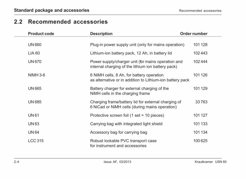
2.2 Recommended accessories
Product code Description Order number
UN 660 Plug-in power supply unit (only for mains operation) 101 128
LIA 60 Lithium-ion battery pack, 12 Ah, in battery lid 102 443
UN 670 Power supply/charger unit (for mains operation and 102 444internal charging of the lithium ion battery pack)
NIMH 3-6 6 NiMH cells, 8 Ah, for battery operation 101 126as alternative or in addition to Lithium-ion battery pack
UN 665 Battery charger for external charging of the 101 129NiMH cells in the charging frame
UN 685 Charging frame/battery lid for external charging of 33 7636 NiCad or NiMH cells (during mains operation)
UN 61 Protective screen foil (1 set = 10 pieces) 101 127
UN 63 Carrying bag with integrated light shield 101 133
UN 64 Accessory bag for carrying bag 101 134
LCC 315 Robust lockable PVC transport case 100 625for instrument and accessories
Krautkramer USN 60 Issue AF, 03/2013 2-5
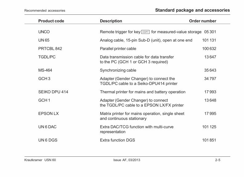
Standard package and accessoriesRecommended accessories
Product code Description Order number
UNCO Remote trigger for key c for measured-value storage 05 301
UN 65 Analog cable, 15-pin Sub-D (unit), open at one end 101 131
PRTCBL 842 Parallel printer cable 100 632
TGDL/PC Data transmission cable for data transfer 13 647to the PC (GCH 1 or GCH 3 required)
MS-464 Synchronizing cable 35 643
GCH 3 Adapter (Gender Changer) to connect the 34 797TGDL/PC cable to a Seiko-DPU414 printer
SEIKO DPU 414 Thermal printer for mains and battery operation 17 993
GCH 1 Adapter (Gender Changer) to connect 13 648the TGDL/PC cable to a EPSON LX/FX printer
EPSON LX Matrix printer for mains operation, single sheet 17 995and continuous stationary
UN 6 DAC Extra DAC/TCG function with multi-curve 101 125representation
UN 6 DGS Extra function DGS 101 851
2-6 Issue AF, 03/2013 Krautkramer USN 60
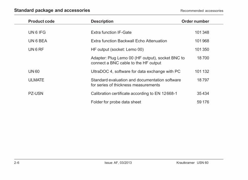
Standard package and accessories
Product code Description Order number
UN 6 IFG Extra function IF-Gate 101 348
UN 6 BEA Extra function Backwall Echo Attenuation 101 968
UN 6 RF HF output (socket: Lemo 00) 101 350
Adapter: Plug Lemo 00 (HF output), socket BNC to 18 700connect a BNC cable to the HF output
UN 60 UltraDOC 4, software for data exchange with PC 101 132
ULMATE Standard evaluation and documentation software 18 797for series of thickness measurements
PZ-USN Calibration certificate according to EN 12668-1 35 434
Folder for probe data sheet 59 176
Recommended accessories

Krautkramer USN 60 Issue AF, 03/2013 3-1
Initial start-up 3
3-2 Issue AF, 03/2013 Krautkramer USN 60
Initial start-up Setting up the USN 60
3.1 Setting up the USN 60
Place the USN 60 on a flat and even base surface sothat you can easily read the screen display.
If the instrument has been brought in from a cold roominto a warmer room, wait until it has adapted to theroom temperature before you turn it on (to avoid ofcondensation).
3.2 Power supply
The USN 60 can be operated using a plug-in powersupply unit, or by means of batteries.
You can connect the USN 60 to mains supply even if ithas batteries inserted into it. The battery power is thenautomatically interrupted.
Operation using plug-in power supply unitYou should exclusively use the plug-in power supplyunit UN 660 recommended by us for the operation withplug-in power supply unit.
Mains adapter
The power supply unit included in the supply is equippedwith two different plug adapters – for the European andfor the U.S. standard. If the adapter plugged on yourpower supply unit does not correspond to your plugstandard, you can exchange it.
– To do this, simply pull off the plug-on adapter, andreplace it with the required one.
Krautkramer USN 60 Issue AF, 03/2013 3-3
Initial start-upPower supply
H Note:
Exchange the plug adapter only once;the plug-in power supply unit is not suitable for frequentchanges.
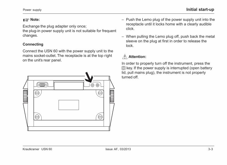
Connecting
Connect the USN 60 with the power supply unit to themains socket-outlet. The receptacle is at the top righton the unit’s rear panel.
– Push the Lemo plug of the power supply unit into thereceptacle until it locks home with a clearly audibleclick.
– When pulling the Lemo plug off, push back the metalsleeve on the plug at first in order to release thelock.
A Attention:
In order to properly turn off the instrument, press theo key. If the power supply is interrupted (open batterylid, pull mains plug), the instrument is not properlyturned off.
3-4 Issue AF, 03/2013 Krautkramer USN 60
Initial start-up Power supply
Operation using Lithium-Ion storagebatteryA powerful Lithium-Ion storage battery is available forthe USN 60 as an option (ref. chapter 2.2 Recommendedaccessories). The Lithium-Ion storage battery has ahigh capacity and therefore ensures a long operatingtime of the USN 60.
Installing the Lithium-Ion storage battery
The Lithium-Ion storage battery is delivered perma-nently installed in a battery lid. Before installing it, youmay first have to remove any battery lid used previ-ously.
– If necessary, unscrew the four screws of the batterycompartment and remove the battery lid with the6 D-cells.
– Place the battery lid including the Lithium-Ionstorage battery on the battery compartment and re-tighten all four screws manually.
H Note:
To charge the Lithium-Ion storage battery, you have touse the special power supply/charger unit UN 670.
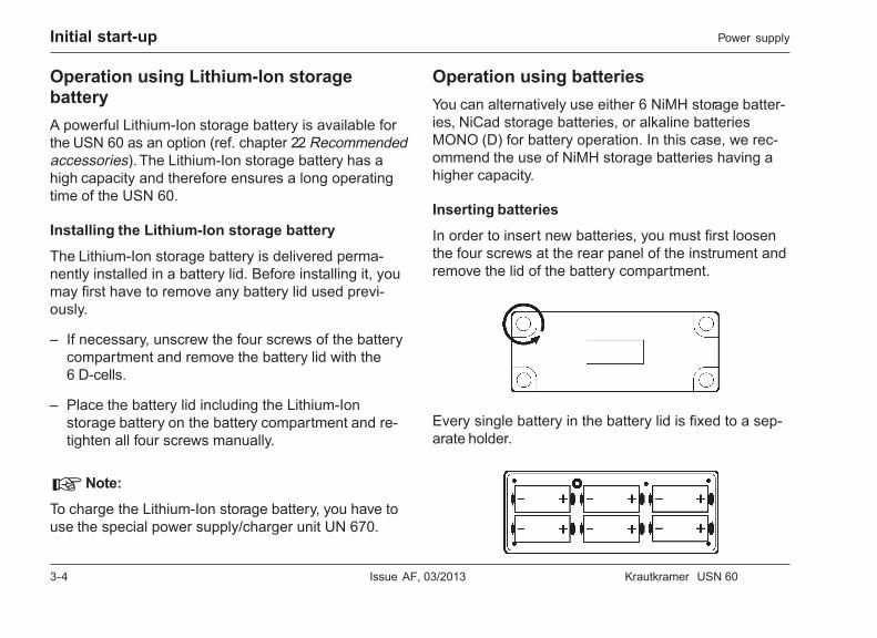
Operation using batteriesYou can alternatively use either 6 NiMH storage batter-ies, NiCad storage batteries, or alkaline batteriesMONO (D) for battery operation. In this case, we rec-ommend the use of NiMH storage batteries having ahigher capacity.
Inserting batteries
In order to insert new batteries, you must first loosenthe four screws at the rear panel of the instrument andremove the lid of the battery compartment.
Every single battery in the battery lid is fixed to a sep-arate holder.
Krautkramer USN 60 Issue AF, 03/2013 3-5
Initial start-upPower supply
– Loosen the four screws of the battery lid.
– Insert the batteries into the battery lid.
– Close the battery compartment.
H Note:
Check the correct polarity when inserting the batteries.
Selecting the battery typeIn order to achieve the best possible mode of function-ing of the USN 60 in battery operation, you have toselect the battery type to be used. The USN 60 offersyou the following options.
• LITHIUM – lithium-ion storage battery
• NiMH – metal hydrid storage batteries
• NiCAD – nickel-cadmium storage batteries
• ALKALINE – alkaline batteries
– Turn the instrument on. To do this, keep the o keypressed down until the LEDs are lit and an audiblesignal sounds.
– Use the u key to go to the submenu BASIC.
– Use the u key to select the function groupOPTIONS.
– Use the v key to select the function BATTERYTYPE.
– Use the right-hand rotary knob to select the batterytype to be used.
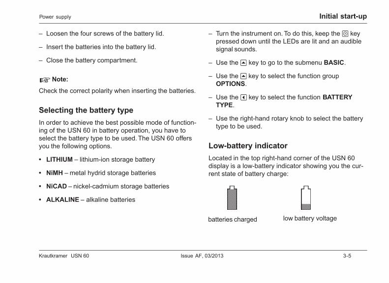
Low-battery indicatorLocated in the top right-hand corner of the USN 60display is a low-battery indicator showing you the cur-rent state of battery charge:
batteries charged low battery voltage
3-6 Issue AF, 03/2013 Krautkramer USN 60
Initial start-up
H Notes:
The low-battery indicator only indicates the correctbattery charge if you have selected the battery type tobe used in the function BATTERY TYPE .
If the low-battery indicator indicates a low batterycharge, you should exchange the batteries as soon aspossible.
The USN 60 is turned off automatically if the operationis no longer ensured. In the case of prolonged fieldoperations, we recommend you to carry a second setof charged batteries with you.
All settings remain saved during battery exchange, andthey are immediately available again afterwards.
Used or defective batteries are special waste and mustbe disposed of according to the legal provisions. Youshould exclusively use the NiMH 3-6 products recom-mended by us for battery operation.
Charging of batteries
NiMH storage batteries
NiMH storage batteries can only be charged using an ex-ternal battery charger. You need the charging frame UN 685as well as the battery charger UN 665 for this purpose.
Lithium-Ion storage battery
To charge the Lithium-Ion storage battery, you need thespecial power supply/charger unit UN 670.
The standard package of the charger unit includes abrief operating manual describing the charging proce-dure. Please read this description before connectingthe charger unit.
H Note:
You can charge the Lithium-Ion storage battery duringnormal operation. You don’t have to remove the batterylid for this purpose but only connect the charger unitwith the connection on the battery lid.
You can charge a separate Lithium-Ion storage batteryby connecting it (or the battery lid) to the charger unit.The battery lid does not have to be installed on theUSN 60 for this purpose.
Power supply
Krautkramer USN 60 Issue AF, 03/2013 3-7
Initial start-up
3.3 Connecting a probe
In order to prepare the USN 60 for operation, you haveto connect a probe.
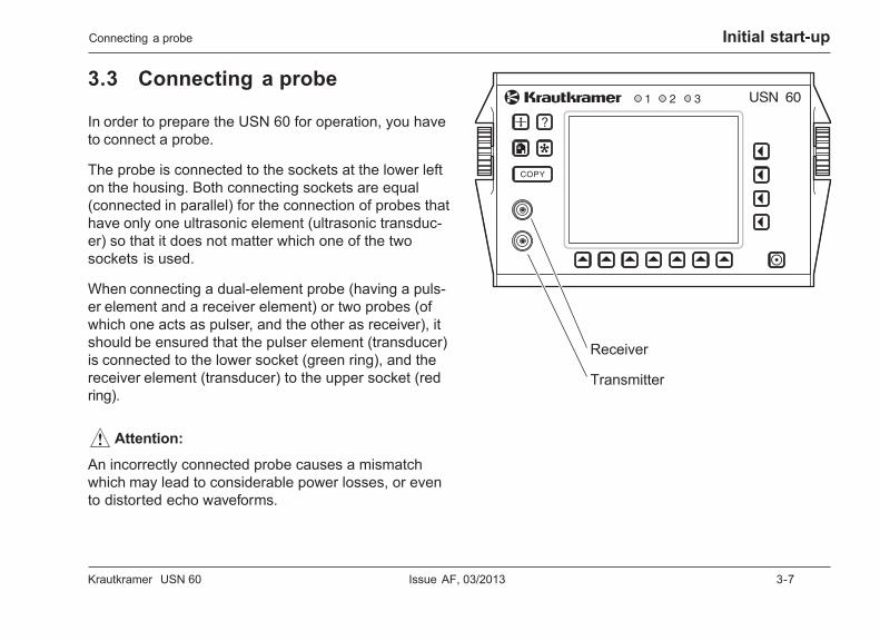
The probe is connected to the sockets at the lower lefton the housing. Both connecting sockets are equal(connected in parallel) for the connection of probes thathave only one ultrasonic element (ultrasonic transduc-er) so that it does not matter which one of the twosockets is used.
When connecting a dual-element probe (having a puls-er element and a receiver element) or two probes (ofwhich one acts as pulser, and the other as receiver), itshould be ensured that the pulser element (transducer)is connected to the lower socket (green ring), and thereceiver element (transducer) to the upper socket (redring).
A Attention:
An incorrectly connected probe causes a mismatchwhich may lead to considerable power losses, or evento distorted echo waveforms.
Connecting a probe
Receiver
Transmitter
3-8 Issue AF, 03/2013 Krautkramer USN 60
Initial start-up
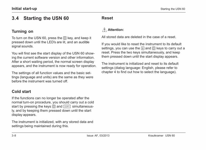
3.4 Starting the USN 60
Turning onTo turn on the USN 60, press the o key, and keep itpressed down until the LED’s are lit, and an audiblesignal sounds.
You will first see the start display of the USN 60 show-ing the current software version and other information.After a short waiting period, the normal screen displayappears, and the instrument is now ready for operation.
The settings of all function values and the basic set-tings (language and units) are the same as they werebefore the instrument was turned off.
Cold startIf the functions can no longer be operated after thenormal turn-on procedure, you should carry out a coldstart by pressing the keys o and c simultaneous-ly, and by keeping them pressed down until the startdisplay appears.
The instrument is initialized, with any stored data andsettings being maintained during this.
Reset
A Attention:
All stored data are deleted in the case of a reset.
If you would like to reset the instrument to its defaultsettings, you can use the w and o keys to carry out areset. Press the two keys simultaneously, and keepthem pressed down until the start display appears.
The instrument is initialized and reset to its defaultsettings (dialog language: English, please refer tochapter 4 to find out how to select the language).
Starting the USN 60
Krautkramer USN 60 Issue AF, 03/2013 4-1
Fundamental principles of operation 4
4-2 Issue AF, 03/2013 Krautkramer USN 60
Fundamental principles of operation Control elements
4.1 Control elements
Krautkramer USN 60 Issue AF, 03/2013 4-3
Fundamental principles of operationControl elements
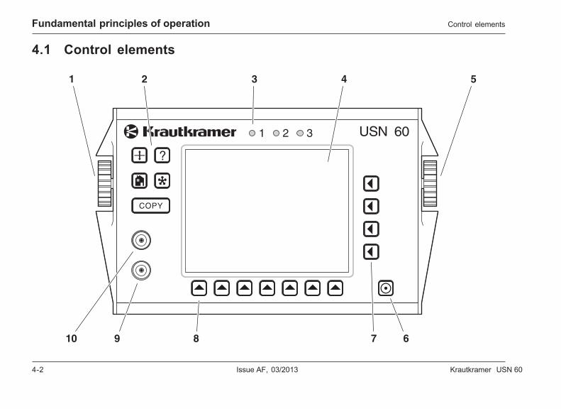
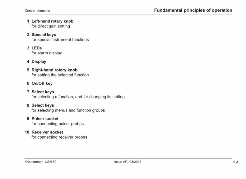
1 Left-hand rotary knobfor direct gain setting
2 Special keysfor special instrument functions
3 LEDsfor alarm display
4 Display
5 Right-hand rotary knobfor setting the selected function
6 On/Off key
7 Select keysfor selecting a function, and for changing its setting
8 Select keysfor selecting menus and function groups
9 Pulser socketfor connecting pulser probes
10 Receiver socketfor connecting receiver probes
4-4 Issue AF, 03/2013 Krautkramer USN 60
Fundamental principles of operation Display
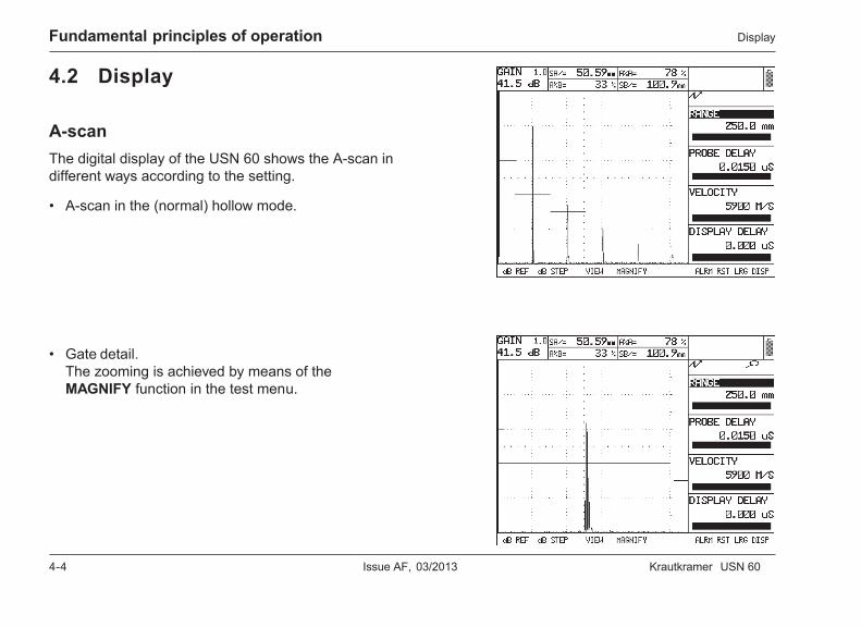
4.2 Display
A-scanThe digital display of the USN 60 shows the A-scan indifferent ways according to the setting.
• A-scan in the (normal) hollow mode.
• Gate detail.The zooming is achieved by means of theMAGNIFY function in the test menu.
Krautkramer USN 60 Issue AF, 03/2013 4-5
Fundamental principles of operationDisplay
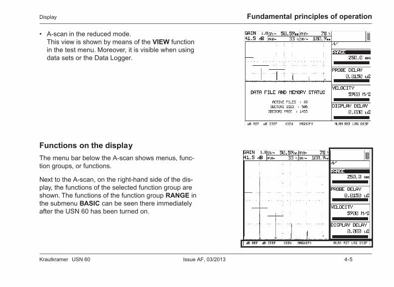
• A-scan in the reduced mode.This view is shown by means of the VIEW functionin the test menu. Moreover, it is visible when usingdata sets or the Data Logger.
Functions on the displayThe menu bar below the A-scan shows menus, func-tion groups, or functions.
Next to the A-scan, on the right-hand side of the dis-play, the functions of the selected function group areshown. The functions of the function group RANGE inthe submenu BASIC can be seen there immediatelyafter the USN 60 has been turned on.

4-6 Issue AF, 03/2013 Krautkramer USN 60
Fundamental principles of operation Display
Displays above the A-scan
Gain field
The current gain is displayed on the left above theA-scan. In addition, you can see the incrementation forgain variation in this field.
Display boxes for readings
Four small display boxes, and a large one, are avail-able above the A-scan for the display of readings. Thefour small display boxes enable to display four differentreadings at the same time. One of these readings canbe additionally displayed in the large display box. Thecontents of the display boxes depend on the settingsof the functions RESULTS and dB REF.
Low-battery indicator
Located next to the large display box, on its right-handside, is the low-battery indicator showing you the cur-rent state of battery charge.
Krautkramer USN 60 Issue AF, 03/2013 4-7
Fundamental principles of operationDisplay
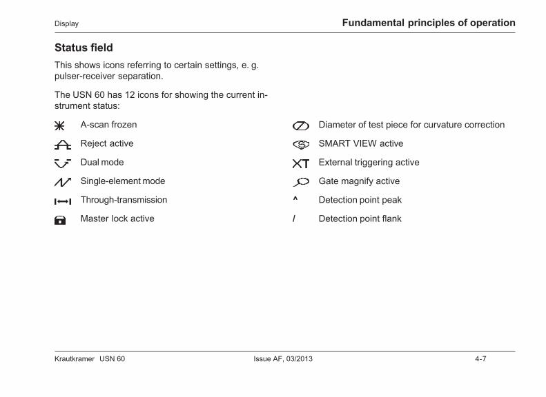
Status fieldThis shows icons referring to certain settings, e. g.pulser-receiver separation.
The USN 60 has 12 icons for showing the current in-strument status:
A-scan frozen
Reject active
Dual mode
Single-element mode
Through-transmission
Master lock active
Diameter of test piece for curvature correction
SMART VIEW active
External triggering active
Gate magnify active
^ Detection point peak
/ Detection point flank
4-8 Issue AF, 03/2013 Krautkramer USN 60
Fundamental principles of operation Keys and rotary knobs
4.3 Keys and rotary knobs
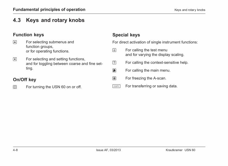
Function keysu For selecting submenus and
function groups,or for operating functions.
v For selecting and setting functions,and for toggling between coarse and fine set-ting.
On/Off keyo For turning the USN 60 on or off.
Special keysFor direct activation of single instrument functions:
w For calling the test menuand for varying the display scaling.
? For calling the context-sensitive help.
h For calling the main menu.
f For freezing the A-scan.
c For transferring or saving data.

Krautkramer USN 60 Issue AF, 03/2013 4-9
Fundamental principles of operationKeys and rotary knobs
Rotary knobsThe USN 60 is equipped with two rotary knobs.
The left-hand rotary knob enables you to directly setthe gain; the right-hand rotary knob serves for settingthe currently selected function. Both rotary knobs arealso needed when editing texts.
The two rotary knobs enable both step-by-step andaccelerated settings. You can define a setting step bystep by slightly operating the rotary knob which willsnap into place at the next setting. To accelerate thesetting, operate the rotary knob continuously, i. e. at aconstant speed. This enables you to quickly bridgegreat differences between the settings.
4.4 Help function
The USN 60 keeps a help function available which youcan activate by means of the ? key. You can call thehelp on any active function group. The help gives youinformation on how to handle the functions of the ac-tive function group.
– Press the ? key in order to call the help on the ac-tive function group.
– Press the ? key another time in order to make thehelp disappear.
4-10 Issue AF, 03/2013 Krautkramer USN 60
Fundamental principles of operation
4.5 Operating concept
The USN 60 is an easy-to-use instrument. The func-tions of the USN 60 are arranged in two menu catego-ries.
• The main menu offers you six submenus for aneasy instrument configuration. The submenus con-tain several function groups, each consisting of fourfunctions. You can use the main menu to define allsettings required for the preparation of a test.
• The test menu offers you a quick access to six func-tions. All functions of the test menu can even be op-erated with a frozen A-scan.
Operating functions in the main menuYou will find all functions for the configuration of theUSN 60 in the main menu. You can use the h key tocall the main menu. The corresponding submenus aredisplayed in the menu bar.
In order to go to a submenu, press the correspondingu key. The corresponding function groups are nowdisplayed in the menu bar, with the first function groupbeing highlighted. The corresponding functions may beseen to the right of the A-scan.
H Note:
You can easily recognize whether you’re in the mainmenu or in a submenu. If you have selected a sub-menu, one of the function groups is always highlightedin the menu bar. If the main menu is selected, nothingis highlighted in the menu bar.
Go to the required function group by selecting it usingthe u key. The selected function group is highlighted,and the corresponding functions are shown to the rightof the A-scan.
Operating concept
Krautkramer USN 60 Issue AF, 03/2013 4-11
Fundamental principles of operation
To select the individual functions, use the correspond-ing v keys. The selected function is now highlighted.
The USN 60 offers you two options for setting high-lighted functions. Using the right-hand rotary knob, youcan set any highlighted function. You can also setmany functions by repeatedly pressing the corre-sponding v key.
In the case of functions for setting numerical values,an additional bar having a vertical line is displayed be-low the value. The position of the line in the bar indi-cates the current setting relatively to the setting rangeavailable. You can exclusively set these functions us-ing the right-hand rotary knob.
Coarse and fine setting of functions
Some functions allow you to choose between coarseand fine setting.
The fine setting is identified by the function spellingusing small letters, the coarse setting accordingly bycapital letters.
In order to toggle between coarse and fine setting,press the corresponding v key several times.
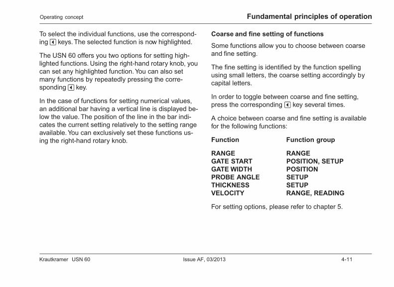
A choice between coarse and fine setting is availablefor the following functions:
Function Function group
RANGE RANGEGATE START POSITION, SETUPGATE WIDTH POSITIONPROBE ANGLE SETUPTHICKNESS SETUPVELOCITY RANGE, READING
For setting options, please refer to chapter 5.
Operating concept
4-12 Issue AF, 03/2013 Krautkramer USN 60
Fundamental principles of operation
Operating functions in the test menuYou have a quick access to six functions in the testmenu.
To call the test menu, press the w key once. The func-tions of the test menu are shown in the menu bar.
You can operate the functions pressing the corre-sponding u key. The function is immediately carriedout.
Using the text editorThe USN 60 makes it possible to you to key in yourown texts. The texts are displayed in a specific textbox and can be edited using an Editor menu and therotary knobs.
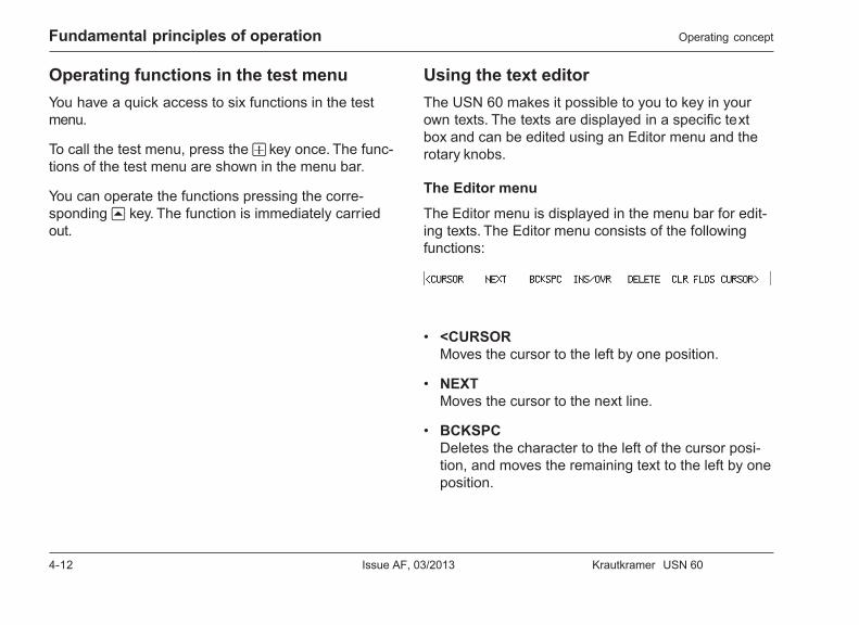
The Editor menu
The Editor menu is displayed in the menu bar for edit-ing texts. The Editor menu consists of the followingfunctions:
• <CURSORMoves the cursor to the left by one position.
• NEXTMoves the cursor to the next line.
• BCKSPCDeletes the character to the left of the cursor posi-tion, and moves the remaining text to the left by oneposition.
Operating concept

Krautkramer USN 60 Issue AF, 03/2013 4-13
Fundamental principles of operation
• INS/OVRToggles between insert and overwrite mode, withthe selected mode being displayed in the top right-hand corner of the text box.
• DELETEDeletes the highlighted character.
• CLR FLDSClears all fields.
• CURSOR>Moves the cursor to the right by one position.
You can operate the functions by pressing the corre-sponding u key. The function is immediately carriedout.
The rotary knobs
Besides the Editor menu, you also need the two rotaryknobs for editing texts.
Use the left-hand rotary knob to move the cursor tothe left or right within a line.
Use the right-hand rotary knob to select the characterthat you want to insert at the cursor position.
Function fields
There are additional functions available to you in somefunction groups for the purpose of editing texts. Formore details on this, please read the description of thecorresponding function group in chapter 5.
Example: Editing file header
This example explains the procedure of editing texts.Proceed as follows in order to edit the file header:
– If necessary, go to the main menu.
– Go to the submenu FILES.
– Select the function group REP HEAD. TheA-scan is displayed in reduced mode, and the textbox for editing file headers is located below theA-scan. The text box contains 9 lines with one titleand one data field each.
– Go to the function EDIT and use the right-hand ro-tary knob to choose the option ON. The number ofthe first header line is highlighted, and the cursor isat the first position in the corresponding data field.The display in the menu bar changes to the Editormenu.
Operating concept

4-14 Issue AF, 03/2013 Krautkramer USN 60
Fundamental principles of operation
– Use the right-hand rotary knob to choose a characterto be inserted at the cursor position.
– Move the cursor to the right by one position usingCURSOR>, or use the left-hand rotary knob tomove the cursor.
– Use the right-hand rotary knob to choose a characterto be inserted at the cursor position.
– Move the cursor to the right by one position usingCURSOR>, or use the left-hand rotary knob tomove the cursor.
– Use the right-hand rotary knob to choose a charac-ter to be inserted at the cursor position.
– Move the cursor to the left by one position using<CURSOR, or use the left-hand rotary knob to movethe cursor.
– Use DELETE if you want to delete the character atthe cursor position.
– Use BCKSPC if you want to delete the characterlocated to the left of the cursor.
– If necessary, edit other characters in the same way.
– Use NEXT to go to the next field in the file header.
– If necessary, edit the field as described previously.
– If necessary, use NEXT to go to other fields in orderto edit them.
– If necessary, use INS/OVR in order to togglebetween insert and overwrite mode. The selectedmode is displayed next to the designationINFORMATION.
– To end the edit process, set the function EDIT toOFF.
H Note:
You can also use an external keyboard connected tothe RS232 interface to edit text fields (please see alsochapter 15).
Operating concept
Krautkramer USN 60 Issue AF, 03/2013 4-15
Fundamental principles of operation
4.6 Important regional basicsettings
Before using the USN 60, you must define a few re-gional basic settings. You can use the function groupREGIONAL in the submenu BASIC to define language,date, time, and units of measurement.
– If necessary, go to the main menu.
– Select the submenu BASIC.
– Select the function group REGIONAL.
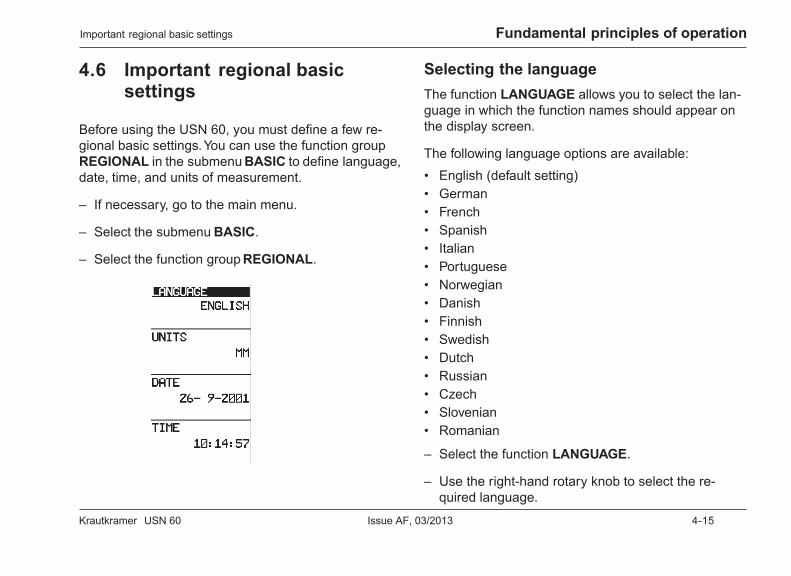
Selecting the languageThe function LANGUAGE allows you to select the lan-guage in which the function names should appear onthe display screen.
The following language options are available:• English (default setting)• German• French• Spanish• Italian• Portuguese• Norwegian• Danish• Finnish• Swedish• Dutch• Russian• Czech• Slovenian• Romanian
– Select the function LANGUAGE.
– Use the right-hand rotary knob to select the re-quired language.
Important regional basic settings
4-16 Issue AF, 03/2013 Krautkramer USN 60
Fundamental principles of operation
Selecting the units of measurementUse the function UNITS to choose the required unitsfrom mm, inch or µsec.
– Select the function UNITS.
– Use the right-hand rotary knob to select the re-quired units.
Setting the dateYou can use the function DATE to set the current date.
– Select the function DATE. The date is displayed inthe format DD-MM-YYYY.
– Use v to change between day, month, and year.
– Use the right-hand rotary knob to set the requireddate.
Setting the timeThe function TIME serves for setting the current hourof time.
– Select the function TIME. The preset time is dis-played in the 24-hour format.
– Use v to toggle between hours and minutes.
– Use the right-hand rotary knob to set the requiredtime.
A Attention:
Remember to manually adjust the time changing be-tween winter and summer time.
Important regional basic settings
Krautkramer USN 60 Issue AF, 03/2013 4-17
Fundamental principles of operation
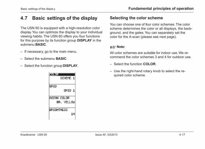
4.7 Basic settings of the display
The USN 60 is equipped with a high-resolution colordisplay. You can optimize the display to your individualviewing habits. The USN 60 offers you four functionsfor this purpose by its function group DISPLAY in thesubmenu BASIC.
– If necessary, go to the main menu.
– Select the submenu BASIC.
– Select the function group DISPLAY.
Selecting the color schemeYou can choose one of four color schemes. The colorscheme determines the color or all displays, the back-ground, and the gates. You can separately set thecolor for the A-scan (please see next page).
H Note:
All color schemes are suitable for indoor use. We re-commend the color schemes 3 and 4 for outdoor use.
– Select the function COLOR.
– Use the right-hand rotary knob to select the re-quired color scheme.
Basic settings of the displa y
4-18 Issue AF, 03/2013 Krautkramer USN 60
Fundamental principles of operation
Selecting the gridThe USN 60 offers you a choice between two grids:
• OFF – No grid
• GRID1 – Five horizontal and vertical lines each
• GRID2 – Ten horizontal and vertical lines each
– Select the function GRID.
– Use the right-hand rotary knob to select the requiredgrid.
Selecting the A-scan colorYou can separately select the color for the A-scan.When doing this, you have a choice between the fol-lowing colors:
• BLUE
• GREEN
• CYAN
• RED
• MAGENTA
• ORANGE
• WHITE
• BR. YELLOW
– Select the function ASCAN COLOR.
– Use the right-hand rotary knob to select the re-quired color.
Basic settings of the displa y
Krautkramer USN 60 Issue AF, 03/2013 4-19
Fundamental principles of operation
Setting the brightnessYou can set the brightness of the display from 0 ... 20.The setting 0 corresponds to the lowest and 20 to thehighest brightness in this connection.
H Note:
High brightness increases the power consumption andconsequently reduces the operating time in batteryoperation.
– Select the function BRIGHTNESS.
– Use the right-hand rotary knob to set the requiredbrightness.
Basic settings of the displa y
4-20 Issue AF, 03/2013 Krautkramer USN 60

Krautkramer USN 60 Issue AF, 03/2013 5-1
The main menu 5
5-2 Issue AF, 03/2013 Krautkramer USN 60
The main menu Overview of the menu
5.1 Overview of the menu
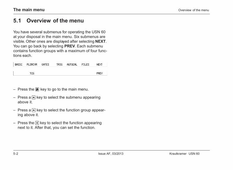
You have several submenus for operating the USN 60at your disposal in the main menu. Six submenus arevisible. Other ones are displayed after selecting NEXT.You can go back by selecting PREV. Each submenucontains function groups with a maximum of four func-tions each.
– Press the h key to go to the main menu.
– Press a u key to select the submenu appearingabove it.
– Press a u key to select the function group appear-ing above it.
– Press the v key to select the function appearingnext to it. After that, you can set the function.
Krautkramer USN 60 Issue AF, 03/2013 5-3
The main menuThe submenu BASIC
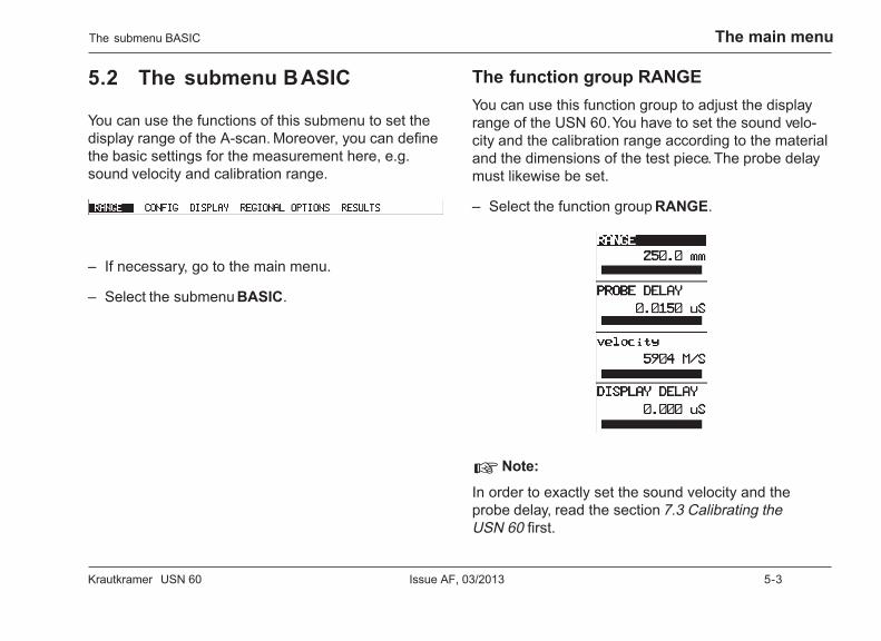
5.2 The submenu BASIC
You can use the functions of this submenu to set thedisplay range of the A-scan. Moreover, you can definethe basic settings for the measurement here, e.g.sound velocity and calibration range.
– If necessary, go to the main menu.
– Select the submenu BASIC.
The function group RANGEYou can use this function group to adjust the displayrange of the USN 60. You have to set the sound velo-city and the calibration range according to the materialand the dimensions of the test piece. The probe delaymust likewise be set.
– Select the function group RANGE.
H Note:
In order to exactly set the sound velocity and theprobe delay, read the section 7.3 Calibrating theUSN 60 first.
5-4 Issue AF, 03/2013 Krautkramer USN 60
The main menu
RANGE
Set the display range to be shown on the displayscreen here.
• Coarse settingfrom 1 mm to 5000 mm in large steps
• Fine settingup to 99.99 mm in steps of 0.01 mmup to 999 mm in steps of 0.1 mmup to 5000 mm in steps of 1 mm
– Select the function RANGE.
– If necessary, use the v key to toggle betweencoarse and fine setting.
– Use the right-hand rotary knob to set the requireddisplay range.
H Note:
The range limits also depend on the sound velocitysetting: In the case of low sound velocities, the rangelimits move downward, in the case of high ones, theymove upward.
PROBE DELAY
Every probe has a delay line between the transducerelement and the coupling face. The ultrasonic pulsemust therefore first pass through this delay line beforeit can enter the test piece. You can compensate for thisinfluence of the delay line in the probe with the functionPROBE DELAY.
– Select the function PROBE DELAY.
– Use the right-hand rotary knob to set the requiredprobe delay.
H Note:
If the value for PROBE DELAY is not known, read thesection 7.3 Calibrating the USN 60 first in order to de-termine this value.
The submenu BASIC
Krautkramer USN 60 Issue AF, 03/2013 5-5
The main menu
VELOCITY
This is where you’re free to set the sound velocity inthe test piece. The USN 60 uses the sound velocity forcalculating intervals and distances.
A Attention:
The sound velocity must always be correctly set.Otherwise the USN 60 will calculate wrong intervalsand distances.
H Note:
As an alternative, you can use the function MATERIALto set a sound velocity stored in the instrument.
– Select the function VELOCITY.
– Press the v key next to it another time in order tochange to free setting. The function is now shown insmall letters.
– Use the right-hand rotary knob to vary the sound ve-locity.
– If necessary, press the corresponding v key to goback to a predefined sound velocity. A prompt toconfirm appears.
– Confirm with h . The predefined sound velocity is setagain, and the function VELOCITY is shown in capi-tal letters.
DISPLAY DELAY
This function enables you to move the display delay ofthe A-scan on the display screen, with the zero beingmaintained. This is useful if you only want to view acertain detail section of the test object.
– Select the function DISPLAY DELAY.
– Use the right-hand rotary knob to move the A-scanto the left or to the right.
The submenu BASIC
5-6 Issue AF, 03/2013 Krautkramer USN 60
The main menu
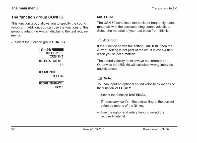
The function group CONFIGThis function group allows you to specify the soundvelocity. In addition, you can use the functions of thisgroup to adapt the A-scan display to the test require-ments.
– Select the function group CONFIG.
MATERIAL
The USN 60 contains a stored list of frequently testedmaterials with the corresponding sound velocities.Select the material of your test piece from this list.
A Attention:
If the function shows the setting CUSTOM, then thecurrent setting is not par t of the list. It is overwrittenwhen you select a material.
The sound velocity must always be correctly set.Otherwise the USN 60 will calculate wrong intervalsand distances.
H Note:
You can input an optional sound velocity by means ofthe function VELOCITY.
– Select the function MATERIAL.
– If necessary, confirm the overwriting of the currentvalue by means of the h key.
– Use the right-hand rotary knob to select therequired material.
The submenu BASIC

Krautkramer USN 60 Issue AF, 03/2013 5-7
The main menu
DISPLAY START
In DISPLAY START, you can choose whether you wantto display the set display range from the initial pulse(IP) or from the test piece surface (IF). In this way, youwill move the complete A-scan with the display zero.
H Note:
This function is only available on instruments havingan optional IF gate.
– Select the function DISPLAY START.
– Use the right-hand rotary knob to select therequired display zero.
ASCAN MODE
The USN 60 offers you several options for the A-scandisplay. You can choose between four A-scan displaymodes:
• HOLLOWThe A-scan only shows contour lines.
• FILLEDThe echoes are shown as filled areas.
• SMART HOLLOWAs HOLLOW but only certainA-scans are taken into consideration.
• SMART FILLEDAs FILLED but only certainA-scans are taken into consideration.
H Note:
The USN 60 normally uses more cycles than can berepresented using the specified A-scan update rate.The represented echoes are a random choice. If youchoose the option SMART HOLLOW or SMARTFILLED, the USN 60 filters the relevant echoes out ofall echoes received, and displays them subsequentlyas an A-scan. The relevance of the echoes in this con-nection refers to the reading displayed in the large dis-play box. For more details on this, please read section7.5 Advanced functions.
– Select the function ASCAN MODE.
– Use the right-hand rotary knob to select therequired display mode.
The submenu BASIC
5-8 Issue AF, 03/2013 Krautkramer USN 60
The main menu
ASCAN ENHANCE
This function allows you to set the display mode of theA-scan on the display screen. The setting options areas follows:
• BASICA-scan in digital display mode.
• SPARKLEDisplay mode of the A-scan is related to an analogdisplay, i.e. RF nodes and echo peaks are shownbrighter.
• BASELINE BREAKIn the rectified mode, the valley points of the half-waves are shown up to the baseline.
• SPRKL+BSEBRKCombination of SPARKLE and BASELINE BREAK.
– Select the function ASCAN ENHANCE.
– Use the right-hand rotary knob to select the requiredoption.
For more details on this function, please read section7.5 Advanced functions.
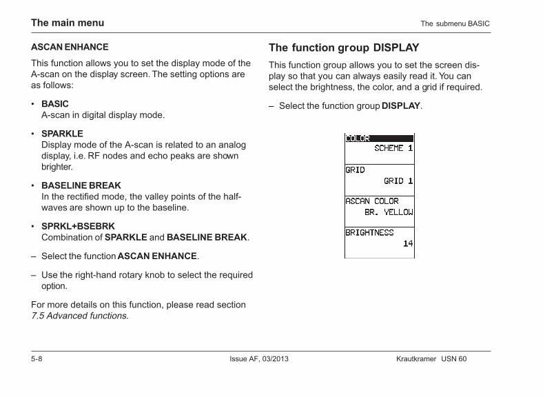
The function group DISPLAYThis function group allows you to set the screen dis-play so that you can always easily read it. You canselect the brightness, the color, and a grid if required.
– Select the function group DISPLAY.
The submenu BASIC

Krautkramer USN 60 Issue AF, 03/2013 5-9
The main menu
COLOR
You can select one of four color schemes. The colorscheme determines the color of all displays, of thebackground, and of the gates. You can separately setthe color for the A-scan.
H Note:
All color schemes are suitable for indoor use. We re-commend the color schemes 3 and 4 for outdoor use.
– Use v to select the function COLOR.
– Use the right-hand rotary knob to select therequired color scheme.
GRID
The USN 60 offers you a choice between two grids:
• OFF – No grid
• GRID1 – Five horizontal and vertical lines each
• GRID2 – Ten horizontal and vertical lines each
– Select the function GRID.
– Use the right-hand rotary knob to select therequired grid.
ASCAN COLOR
You can separately select the color for the A-scan.When doing this, you have a choice between the fol-lowing colors:
• BLUE
• GREEN
• CYAN
• RED
• MAGENTA
• ORANGE
• WHITE
• BR. YELLOW
– Select the function ASCAN COLOR.
– Use the right-hand rotary knob to select therequired color.
The submenu BASIC
5-10 Issue AF, 03/2013 Krautkramer USN 60
The main menu
BRIGHTNESS
You can set the brightness of the display screen from0 ... 20. In this connection, the setting 0 correspondsto minimum and 20 to maximum brightness.
H Note:
High degree of brightness increases the power con-sumption and consequently reduces the operating timein battery operation.
– Select the function BRIGHTNESS.
– Use the right-hand rotary knob to set the requiredbrightness.
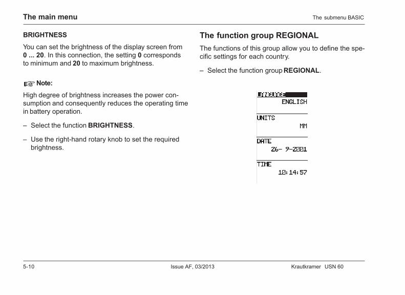
The function group REGIONALThe functions of this group allow you to define the spe-cific settings for each country.
– Select the function group REGIONAL.
The submenu BASIC
Krautkramer USN 60 Issue AF, 03/2013 5-11
The main menu
LANGUAGE
Use the function LANGUAGE to select the language inwhich the function names appear on the display.
The following language options are available:
• English (default setting)• German• French• Spanish• Italian• Portuguese• Norwegian• Danish• Finnish• Swedish• Dutch• Russian• Czech• Slovenian• Romanian
– Select the function LANGUAGE.
– Use the right-hand rotary knob to select therequired language.
UNITS
The function UNITS allows you to choose the requiredunits from mm, inch, or µsec.
– Select the function UNITS.
– Use the right-hand rotary knob to select therequired units.
DATE
You can set the current date in the function DATE.
– Select the function DATE. The date is shown in theformat DD-MM-YYYY.
– Use v to toggle between day, month, and year.
– Use the right-hand rotary knob to set the requireddate.
The submenu BASIC
5-12 Issue AF, 03/2013 Krautkramer USN 60
The main menu
TIME
The function TIME serves for setting the current time.
– Select the function TIME. The preset hour of time isdisplayed in the 24-hour format.
– Use v to toggle between hours and minutes.
– Use the right-hand rotary knob to set the requiredhour of time.
A Attention:
Remember to manually adjust the hour of time whenchanging between winter and summer time.
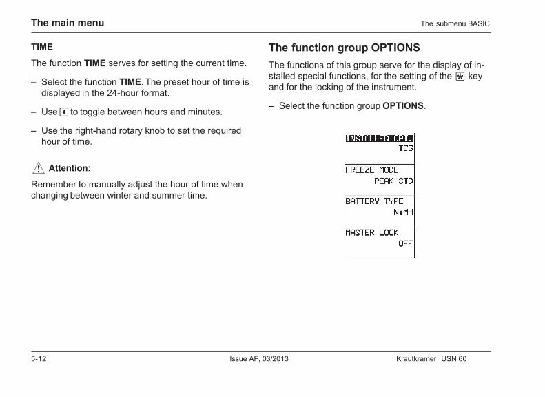
The function group OPTIONSThe functions of this group serve for the display of in-stalled special functions, for the setting of the f keyand for the locking of the instrument.
– Select the function group OPTIONS.
The submenu BASIC
Krautkramer USN 60 Issue AF, 03/2013 5-13
The main menu
INSTALLED OPT.
The basic version of USN 60 can be retrofitted withversatile special functions (options). You can add thesespecial functions to the basic version any time.
The function INSTALLED OPT. enables you to viewthe current range of functions of your USN 60.
H Note:
You can only use the function INSTALLED OPT. forviewing the range of functions of the USN 60 but notfor changing it.
– Select the function INSTALLED OPT.
– Turn the right-hand rotary knob in order to scrollthrough the list of installed special functions.
FREEZE MODE
The USN 60 offers you various options for freezing theA-scan on the display. You can choose between fourdisplay options:
• ALLThe current A-scan is frozen and displayed in theforeground.
• PEAK STD.The current A-scan is frozen and automatically over-written with the following, higher A-scans.
• COMPAREThe frozen A-scan is displayed in the background asa comparison scan while the current A-scan is at thesame time visible in the foreground. To be better ableto distinguish between the two A-scans, the com-parison scan is shown in a weak color, and the cur-rent A-scan in a more intense color.
• ENVELOPEIn addition to the current A-scan, the frozen A-scanis displayed as an envelope. Depending on the set-ting, the frozen A-scan is overwritten after a speci-fied time, or in the case of cer tain events.
The submenu BASIC
5-14 Issue AF, 03/2013 Krautkramer USN 60
The main menu
• ENVELOPE .5S, 1S, 2SThe dynamic A-scan is automatically overwritten af-ter the specified time (0.5s, 1s, or 2s).
• ENVELOPE PEAKThe dynamic A-scan is automatically overwritten ifhigher echoes occur.
H Note:
If the option ALL is chosen, you can change some set-tings even with a frozen A-scan. The gain, the displayrange, and the gate position can be changed within cer-tain limits. The changes are immediately taken intoconsideration when the reading is displayed.
– Select the function FREEZE MODE.
– Use the right-hand rotary knob to select therequired display mode.
BATTERY TYPE
You can use different battery types to operate theUSN 60. In order to obtain the best possible mode offunctioning of the USN 60 in battery operation, youmust set the battery type used. The USN 60 offers youthe following setting options.
• LITHIUM – lithium-ion storage battery
• NiMH – metal-hybrid batteries
• NiCAD – nickel-cadmium batteries
• ALKALINE – alkaline batteries
A Attention:
You should only use the batteries recommended in thismanual to operate the USN 60. Make sure that the se-lected battery type is correctly set. The best possiblemode of functioning of the USN 60 and the correct bat-tery charge indication can only be ensured in this way.
– Select the function BATTERY TYPE.
– Use the right-hand rotary knob to select therequired battery type.
The submenu BASIC
Krautkramer USN 60 Issue AF, 03/2013 5-15
The main menu
MASTER LOCK
This function enables you to protect the current instru-ment settings against undesired changes. The functionMASTER LOCK blocks all settings, except for thegain setting.
H Note:
If the function MASTER LOCK is activated, this is in-dicated with the icon in the status field.
– Select the function MASTER LOCK.
– Use the right-hand rotary knob to selec the requiredoption.
The submenu BASIC
5-16 Issue AF, 03/2013 Krautkramer USN 60
The main menu
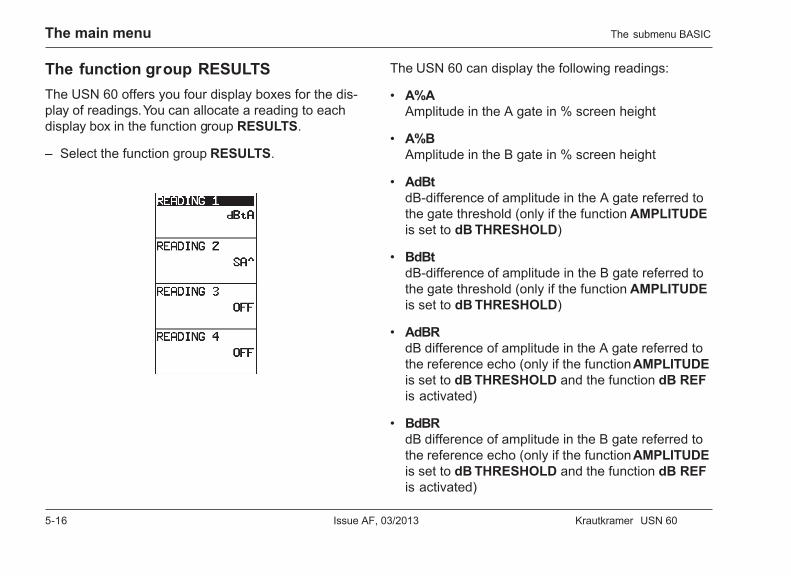
The function group RESULTSThe USN 60 offers you four display boxes for the dis-play of readings. You can allocate a reading to eachdisplay box in the function group RESULTS.
– Select the function group RESULTS.
The USN 60 can display the following readings:
• A%AAmplitude in the A gate in % screen height
• A%BAmplitude in the B gate in % screen height
• AdBtdB-difference of amplitude in the A gate referred tothe gate threshold (only if the function AMPLITUDEis set to dB THRESHOLD)
• BdBtdB-difference of amplitude in the B gate referred tothe gate threshold (only if the function AMPLITUDEis set to dB THRESHOLD)
• AdBRdB difference of amplitude in the A gate referred tothe reference echo (only if the function AMPLITUDEis set to dB THRESHOLD and the function dB REFis activated)
• BdBRdB difference of amplitude in the B gate referred tothe reference echo (only if the function AMPLITUDEis set to dB THRESHOLD and the function dB REFis activated)
The submenu BASIC
Krautkramer USN 60 Issue AF, 03/2013 5-17
The main menu
• SASound path of the echo in the A gate
• SBSound path of the echo in the B gate
• SABSound path difference of the echoes in the gates Aand B
• DAReflector depth in the A gate
• DBReflector depth in the B gate
• PAProjection distance of the echo in the A gate
• PBProjection distance of the echo in the B gate
• RAReduced projection distance in the A gate
• RBReduced projection distance in the B gate
• LANumber of legs in the A gate
• LBNumber of legs in the B gate
• OFFNo measured-value display
H Note:
If you select the readings of the categor ies S, D, P, orR, the corresponding detection point is indicated by anicon in the display box in question. / stands for flankdetection, ^ means peak detection.
READING 1
This is where you can choose the measured value tobe displayed in the small display box at the top left.
– Select the function READING 1.
– Use the right-hand rotary knob to select therequired reading.
The submenu BASIC
5-18 Issue AF, 03/2013 Krautkramer USN 60
The main menu
READING 2
This is where you can choose the measured value tobe displayed in the small display box at the bottomleft.
– Select the function READING 2.
– Use the right-hand rotary knob to select therequired reading.
READING 3
This is where you can choose the measured value tobe displayed in the small display box at the top right.
– Select the function READING 3.
– Use the right-hand rotary knob to select therequired reading.
READING 4
This is where you can choose the measured value tobe displayed in the small display box at the bottomright.
– Select the function READING 4.
– Use the right-hand rotary knob to select therequired reading.
The submenu BASIC
Krautkramer USN 60 Issue AF, 03/2013 5-19
The main menu
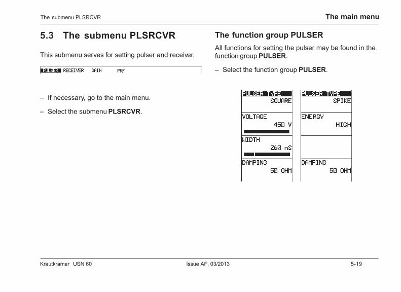
5.3 The submenu PLSRCVR
This submenu serves for setting pulser and receiver.
– If necessary, go to the main menu.
– Select the submenu PLSRCVR.
The function group PULSERAll functions for setting the pulser may be found in thefunction group PULSER.
– Select the function group PULSER.
The submenu PLSRCVR
5-20 Issue AF, 03/2013 Krautkramer USN 60
The main menu
PULSER TYPE
Pulser shape is generally selected based on penetra-tion requirements and/or test standard specifications.Available types include square and spike.
– Select the function PULSER TYPE.
– Use the right-hand rotary knob to select betweenSQUARE and SPIKE.
H Note:
When a SPIKE type pulse is selected, the pulserVOLTAGE and WIDTH functions are disabled. WhenSQUARE type pulse is selected, the EXTERNAL PRFMODE setting is disabled.
VOLTAGE
You can use the function VOLTAGE to set theSQUARE pulser voltage. You can choose a value be-tween 50 and 450 volts in steps of 10.
– Select the function ENERGY.
– Use the right-hand rotary knob to select therequired pulser voltage.
WIDTH
You can use the function WIDTH to set the SQUAREpulser width. You can choose a value between 50 and1000 nanoseconds (ns) in steps of 10.
A recommended starting point from which the widthsetting can be adjusted is found by the following equa-tion:
Nominal width in nanoseconds= 109 : (2 × probe frequency in Hz)
For example, if a 2.25 MHz probe is used, the equationbecomes:
Nominal width in nanoseconds= 109 : (2 × 2.25 × 106) = 222 nanoseconds
– Select the function WIDTH.
– Use the right-hand rotary knob to select therequired pulser width.
H Note:
The pulser voltage and width settings may be auto-matically limited based on the user-selected PRFVALUE setting. This feature acts to limit signal dissipa-tion.
The submenu PLSRCVR
Krautkramer USN 60 Issue AF, 03/2013 5-21
The main menu
ENERGY
You can use the function ENERGY to set the pulservoltage. You can choose between two settings:
• HIGH – high voltage
• LOW – low voltage
The HIGH setting is recommended for all tests requir-ing maximum sensitivity, e.g. for the detection of smallflaws. Choose the LOW setting for broadband probes,or if narrow echoes are required (better lateral resolu-tion).
– Select the function ENERGY.
– Use the right-hand rotary knob to select therequired pulser voltage.
DAMPING
This function serves for matching the probe. You canuse this function to set the damping of the probe oscil-lating circuit and to consequently vary the height,width, and resolution of the echo display.
You have a choice between the settings 50, 75, 150,and 500 ohms. The setting 500 ohms has the lowestdamping effect and results in higher and broaderechoes, the setting 50 ohms reduces the echo height,however, it produces narrow echoes having a higherresolution.
– Select the function DAMPING.
– Use the right-hand rotary knob to select therequired damping.
The submenu PLSRCVR
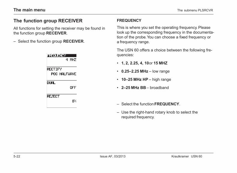
5-22 Issue AF, 03/2013 Krautkramer USN 60
The main menu
The function group RECEIVERAll functions for setting the receiver may be found inthe function group RECEIVER.
– Select the function group RECEIVER.
FREQUENCY
This is where you set the operating frequency. Pleaselook up the corresponding frequency in the documenta-tion of the probe. You can choose a fixed frequency ora frequency range.
The USN 60 offers a choice between the following fre-quencies:
• 1, 2, 2.25, 4, 10 or 15 MHZ
• 0.25–2.25 MHz – low range
• 10–25 MHz HP – high range
• 2–25 MHz BB – broadband
– Select the function FREQUENCY.
– Use the right-hand rotary knob to select therequired frequency.
The submenu PLSRCVR
Krautkramer USN 60 Issue AF, 03/2013 5-23
The main menu
RECTIFY
The function RECTIFY enables you to choose the recti-fication mode of the echo pulses according to your ap-plication. You have the following options to choose from:
• FULLWAVEAll half-waves are displayed above the baseline onthe screen.
• POS HALFWAVEOnly positive half-waves are displayed on thescreen.
• NEG HALFWAVEOnly negative half-waves are displayed on thescreen.
• RFNo rectification.
– Select the function RECTIFY.
– Use the right-hand rotary knob to select therequired rectification mode.
DUAL
You can use this function to toggle between single-element and dual mode:
• ONDual mode; the initial pulse is available at the lowersocket, the upper socket is connected to the ampli-fier input.
• OFFSingle-element mode; the probe connecting socketsare connected in parallel.
• THROUGHAs ON, however, for through-transmission.
– Select the function DUAL.
– Use the right-hand rotary knob to select therequired option.
H Note:
The status of DUAL function is indicated by an icon inthe status field:
OFF
ON
THROUGH
The submenu PLSRCVR
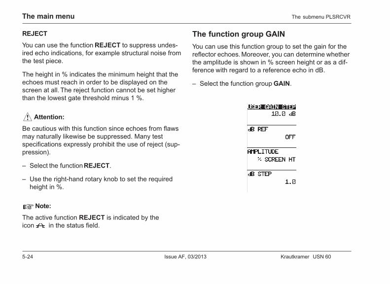
5-24 Issue AF, 03/2013 Krautkramer USN 60
The main menu
REJECT
You can use the function REJECT to suppress undes-ired echo indications, for example structural noise fromthe test piece.
The height in % indicates the minimum height that theechoes must reach in order to be displayed on thescreen at all. The reject function cannot be set higherthan the lowest gate threshold minus 1 %.
A Attention:
Be cautious with this function since echoes from flawsmay naturally likewise be suppressed. Many testspecifications expressly prohibit the use of reject (sup-pression).
– Select the function REJECT.
– Use the right-hand rotary knob to set the requiredheight in %.
H Note:
The active function REJECT is indicated by theicon in the status field.
The function group GAINYou can use this function group to set the gain for thereflector echoes. Moreover, you can determine whetherthe amplitude is shown in % screen height or as a dif-ference with regard to a reference echo in dB.
– Select the function group GAIN.
The submenu PLSRCVR
Krautkramer USN 60 Issue AF, 03/2013 5-25
The main menu
USER GAIN STEP
The USN 60 enables you to vary the gain of the reflec-tor echo. This variation is carried out step by step. Youcan use the function USER GAIN STEP to set an indi-vidual step size for the gain variation.
– Select the function USER GAIN STEP.
– Use the right-hand rotary knob to set the requiredstep size.
dB REF
The function dB REF defines the current echo in thegate as reference echo. The amplitude of all otherechoes in the gate is then indicated as dB differencewith regard to the reference echo in the gain field.
– Select the function dB REF in order to store anecho as reference echo.
– Select the function dB REF in order to display theamplitude in % screen height again.
The activated function dB REF is displayed in the sta-tus field by the icon .
AMPLITUDE
The amplitude is typically displayed in % screenheight. In this function, you can determine the displaymode of the amplitude of the maximum echo in thegate. You have the following options to choose from:
• % SCREEN HTPercentage of screen height
• dB THRESHOLD (dB REF not active)dB difference with regard to the gate threshold
• dB THRESHOLD (dB REF active)dB difference with regard to the recorded referenceecho amplitude
H Note:
Depending on the amplitude setting, the list ofdisplayable readings in the function group RESULTS ofthe submenu BASIC varies.
– Select the function AMPLITUDE.
– Use the right-hand rotary knob to choose therequired option.
The submenu PLSRCVR
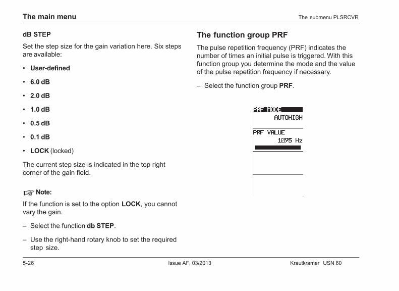
5-26 Issue AF, 03/2013 Krautkramer USN 60
The main menu
dB STEP
Set the step size for the gain variation here. Six stepsare available:
• User-defined
• 6.0 dB
• 2.0 dB
• 1.0 dB
• 0.5 dB
• 0.1 dB
• LOCK (locked)
The current step size is indicated in the top rightcorner of the gain field.
H Note:
If the function is set to the option LOCK, you cannotvary the gain.
– Select the function db STEP.
– Use the right-hand rotary knob to set the requiredstep size.
The submenu PLSRCVR
The function group PRFThe pulse repetition frequency (PRF) indicates thenumber of times an initial pulse is triggered. With thisfunction group you determine the mode and the valueof the pulse repetition frequency if necessary.
– Select the function group PRF.

Krautkramer USN 60 Issue AF, 03/2013 5-27
The main menu
PRF MODE
Make your choice whether the USN 60 should set thepulse repetition frequency automatically, whether youwould like to set it manually, or whether you would liketo use an external pulse generator. You have the follow-ing options to choose from:
• AUTOLOWThe USN 60 automatically sets the PRF value to alow value (25 % of the maximum frequency).
• AUTOHIGHThe USN 60 automatically sets a high PRF value(75 % of the maximum frequency).
• MANUALYou can set the PRF value manually from15 ... 3715 Hz.
• EXTERNALThe USN 60 is externally triggered, e.g. for the setupof multichannel systems.
H Note:
If you select an automatic setting, the USN 60 takesthe display range, the sound velocity, and the gate po-sition settings into consideration when determining thevariable PRF values.
– Select the function PRF MODE.
– Use the right-hand rotary knob to select therequired mode for the PRF value.
H Note:
The option EXTERNAL is only available for the SPIKEpulser type.
If you have chose the option EXTERNAL, a corre-sponding icon is displayed in the status field.
The submenu PLSRCVR
5-28 Issue AF, 03/2013 Krautkramer USN 60
The main menu
PRF VALUE
If you have chosen the option MANUAL in the functionPRF MODE, this is where you can set the pulse repeti-tion frequency (PRF). Otherwise you can only read thepulse repetition frequency here but not vary it.
Make your choice whether you need a maximum PRFvalue, or whether you’re satisfied with a lower value.The larger your workpiece the smaller PRF values arerequired in order to avoid phantom echoes. Withsmaller PRF values, however, the A-scan update ratebecomes lower; high values are therefore required if aworkpiece should be scanned quickly. The best way todetermine the suitable PRF value is by experiment:Start from the highest level, and reduce the value untilthere are no more phantom echoes.
The setting is infinitely variable, the maximum possiblePRF value setting depending on the test range setting.If you exceed the maximum PRF value, the USN 60displays an error message.
– Select the function PRF VALUE.
– Use the right-hand rotary knob to set the requiredPRF value.
The submenu PLSRCVR
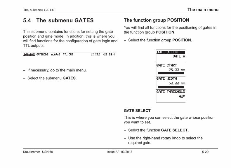
Krautkramer USN 60 Issue AF, 03/2013 5-29
The main menu
5.4 The submenu GATES
This submenu contains functions for setting the gateposition and gate mode. In addition, this is where youwill find functions for the configuration of gate logic andTTL outputs.
– If necessary, go to the main menu.
– Select the submenu GATES.
The function group POSITIONYou will find all functions for the positioning of gates inthe function group POSITION.
– Select the function group POSITION.
GATE SELECT
This is where you can select the gate whose positionyou want to set.
– Select the function GATE SELECT.
– Use the right-hand rotary knob to select therequired gate.
The submenu GATES
5-30 Issue AF, 03/2013 Krautkramer USN 60
The main menu
GATE START
You can define the starting point of gate within thecomplete display range. When doing this, you canchoose between coarse and fine setting.
– Select the function GATE START.
– If necessary, use the v key to toggle betweencoarse and fine setting.
– Use the right-hand rotary knob to select therequired gate start.
GATE WIDTH
You can define the width of the gate within the com-plete display range.
– Select the function GATE WIDTH.
– If necessary, use the v key to toggle betweencoarse and fine setting.
– Use the right-hand rotary knob to set the requiredgate width.
GATE THRESHOLD
This is where you can set the gate threshold in %screen height. The gate threshold marks the tolerancerange of the gate.
You can define the threshold value of the gate withinthe range of 5 ... 90 % screen height the violation ofwhich triggers an alarm with a corresponding setting.
– Select the function GATE THRESHOLD.
– Use the right-hand rotary knob to set the requiredgate threshold.
The submenu GATES
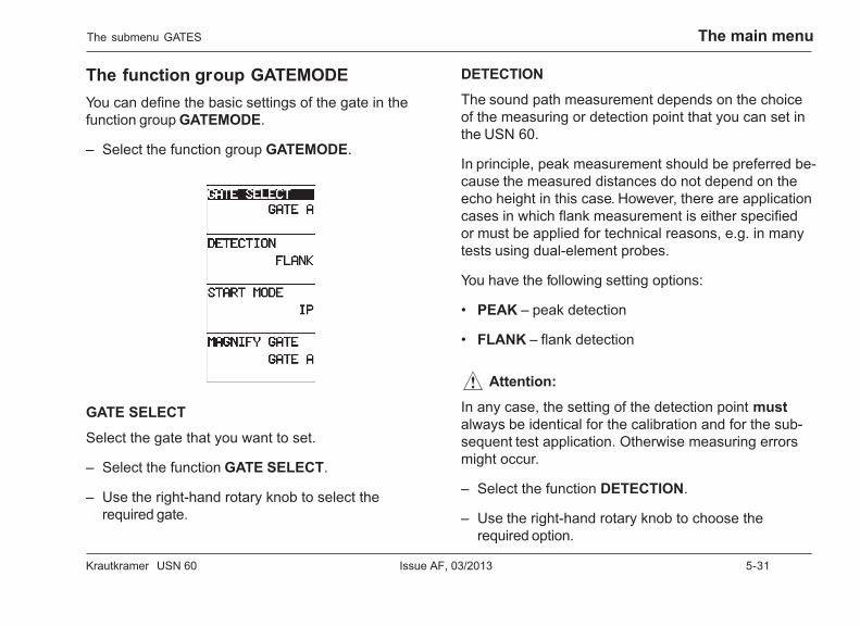
Krautkramer USN 60 Issue AF, 03/2013 5-31
The main menu
The function group GATEMODEYou can define the basic settings of the gate in thefunction group GATEMODE.
– Select the function group GATEMODE.
GATE SELECT
Select the gate that you want to set.
– Select the function GATE SELECT.
– Use the right-hand rotary knob to select therequired gate.
DETECTION
The sound path measurement depends on the choiceof the measuring or detection point that you can set inthe USN 60.
In principle, peak measurement should be preferred be-cause the measured distances do not depend on theecho height in this case. However, there are applicationcases in which flank measurement is either specifiedor must be applied for technical reasons, e.g. in manytests using dual-element probes.
You have the following setting options:
• PEAK – peak detection
• FLANK – flank detection
A Attention:
In any case, the setting of the detection point mustalways be identical for the calibration and for the sub-sequent test application. Otherwise measuring errorsmight occur.
– Select the function DETECTION.
– Use the right-hand rotary knob to choose therequired option.
The submenu GATES
5-32 Issue AF, 03/2013 Krautkramer USN 60
The main menu
H Note:
The selected detection point is displayed as an iconnext to the reading in the display box:
^ PEAK
/ FLANK
START MODE
This is where you can select a point as reference pointfor the gate position.
• IPThe position of gate start is measured from theinitial pulse.
• IFThe position of gate start is measured from theinterface echo (only with installed option IF Gate).
– Select the function START MODE.
– Use the right-hand rotary knob to choose therequired option.
MAGNIFY GATE
When carrying out tests, you can zoom the display ofthe active A-scan range situated within the selectedgate. In this connection, the magnification factor de-pends on the width of the corresponding gate. Therange is magnified until the gate width corresponds tothe display width.
This is where you select the gate to be used for thezoomed A-scan display.
– Select the function MAGNIFY GATE.
– Use the right-hand rotary knob to select therequired gate.
The submenu GATES
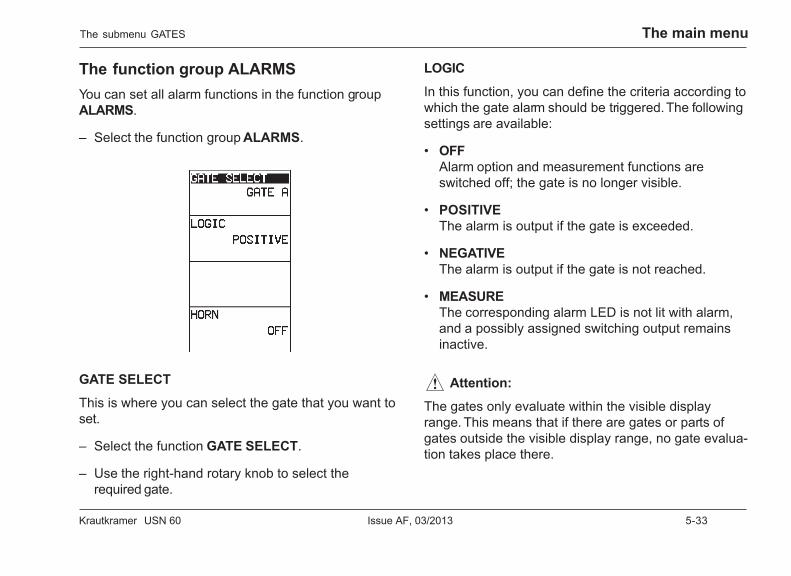
Krautkramer USN 60 Issue AF, 03/2013 5-33
The main menu
The function group ALARMSYou can set all alarm functions in the function groupALARMS.
– Select the function group ALARMS.
GATE SELECT
This is where you can select the gate that you want toset.
– Select the function GATE SELECT.
– Use the right-hand rotary knob to select therequired gate.
LOGIC
In this function, you can define the criteria according towhich the gate alarm should be triggered. The followingsettings are available:
• OFFAlarm option and measurement functions areswitched off; the gate is no longer visible.
• POSITIVEThe alarm is output if the gate is exceeded.
• NEGATIVEThe alarm is output if the gate is not reached.
• MEASUREThe corresponding alarm LED is not lit with alarm,and a possibly assigned switching output remainsinactive.
A Attention:
The gates only evaluate within the visible displayrange. This means that if there are gates or parts ofgates outside the visible display range, no gate evalua-tion takes place there.
The submenu GATES
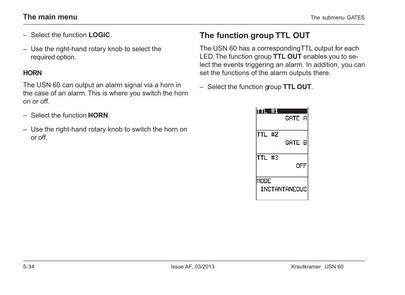
5-34 Issue AF, 03/2013 Krautkramer USN 60
The main menu
– Select the function LOGIC.
– Use the right-hand rotary knob to select therequired option.
HORN
The USN 60 can output an alarm signal via a horn inthe case of an alarm. This is where you switch the hornon or off.
– Select the function HORN.
– Use the right-hand rotary knob to switch the horn onor off.
The function group TTL OUTThe USN 60 has a corresponding TTL output for eachLED. The function group TTL OUT enables you to se-lect the events triggering an alarm. In addition, you canset the functions of the alarm outputs there.
– Select the function group TTL OUT.
The submenu GATES
Krautkramer USN 60 Issue AF, 03/2013 5-35
The main menu
TTL#1, TTL#2, TTL#3
This is where you can assign an alarm event to thecorresponding alarm output and to the pertinent LED. Ifthe alarm event occurs, a signal is output via the alarmoutput, and the corresponding LED at the front panel ofthe instrument is lit.
The TTL outputs can indicate the following alarmevents:
• GATE AAlarm in the A gate.
• GATE BAlarm in the B gate.
• HIGH LIMITThe measured material thickness is too large.
• LOW LIMITThe measured material thickness is too small.
• OFFThe TTL output and the corresponding LED are de-activated.
H Note:
The corresponding LED is not lit in the case of analarm if the option MEASURE is chosen for thefunction LOGIC.
– Select the alarm output and the LED to which youwant to assign an event (TTL#1, TTL#2 or TTL#3).
– Use the right-hand rotary knob to assign the requiredalarm event to the alarm output.
– If necessary, select the next alarm output and as-sign an alarm event to that output.
MODE
This is where you can define the duration of an alarmsignal output in the case of an alarm.
The following settings are available:
• LATCHEDThe alarm signal is output until it’s manually ac-knowledged.
• TIMED 0.25 SECThe alarm signal is output 0.25 seconds longer thanthe alarm period.
The submenu GATES
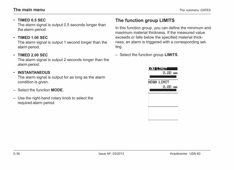
5-36 Issue AF, 03/2013 Krautkramer USN 60
The main menu
• TIMED 0.5 SECThe alarm signal is output 0.5 seconds longer thanthe alarm period.
• TIMED 1.00 SECThe alarm signal is output 1 second longer than thealarm period.
• TIMED 2.00 SECThe alarm signal is output 2 seconds longer than thealarm period.
• INSTANTANEOUSThe alarm signal is output for as long as the alarmcondition is given.
– Select the function MODE.
– Use the right-hand rotary knob to select therequired alarm period.
The function group LIMITSIn this function group, you can define the minimum andmaximum material thickness. If the measured valueexceeds or falls below the specified material thick-ness, an alarm is triggered with a corresponding set-ting.
– Select the function group LIMITS.
The submenu GATES
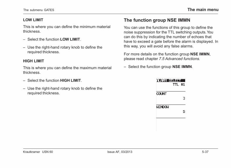
Krautkramer USN 60 Issue AF, 03/2013 5-37
The main menu
LOW LIMIT
This is where you can define the minimum materialthickness.
– Select the function LOW LIMIT.
– Use the right-hand rotary knob to define therequired thickness.
HIGH LIMIT
This is where you can define the maximum materialthickness.
– Select the function HIGH LIMIT.
– Use the right-hand rotary knob to define therequired thickness.
The function group NSE IMMNYou can use the functions of this group to define thenoise suppression for the TTL switching outputs. Youcan do this by indicating the number of echoes thathave to exceed a gate before the alarm is displayed. Inthis way, you will avoid any false alarms.
For more details on the function group NSE IMMN,please read chapter 7.5 Advanced functions.
– Select the function group NSE IMMN.
The submenu GATES
5-38 Issue AF, 03/2013 Krautkramer USN 60
The main menu
ALARM SELECT
This is where you select the TTL output for which youwant to set the noise suppression.
– Select the function ALARM SELECT.
– Use the right-hand rotary knob to select therequired TTL output.
COUNT
This is where you can define the number of echoesthat have to exceed the gate in order to trigger an alarm.
– Select the function COUNT.
– Use the right-hand rotary knob to select therequired number.
WINDOW
This is where you can define the number of transmittercycles in which the flaw echoes must occur before analarm is output. The USN 60 can monitor 2 to 16 trans-mitter cycles.
– Select the function WINDOW.
– Use the right-hand rotary knob to set the requirednumber.
The submenu GATES
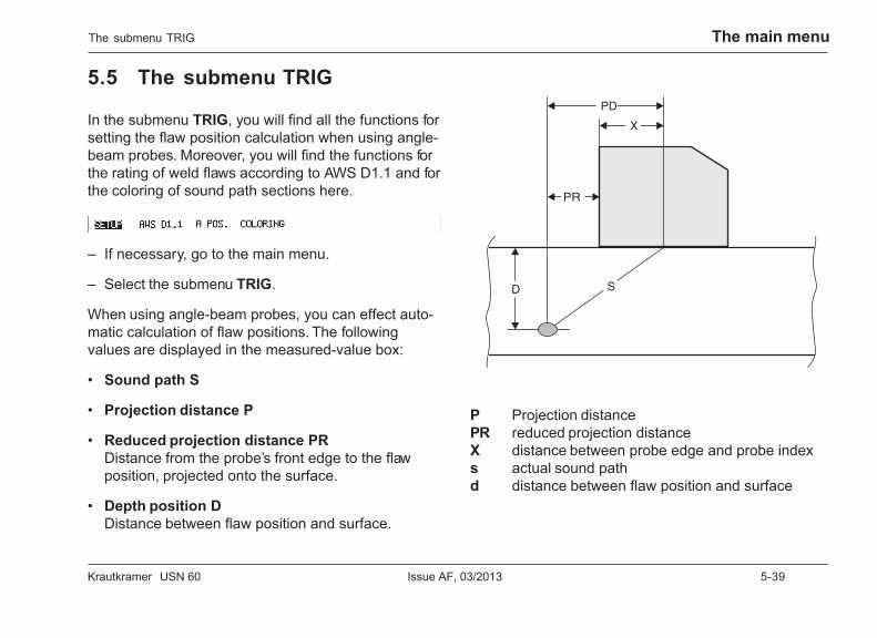
Krautkramer USN 60 Issue AF, 03/2013 5-39
The main menu
5.5 The submenu TRIG
In the submenu TRIG, you will find all the functions forsetting the flaw position calculation when using angle-beam probes. Moreover, you will find the functions forthe rating of weld flaws according to AWS D1.1 and forthe coloring of sound path sections here.
– If necessary, go to the main menu.
– Select the submenu TRIG.
When using angle-beam probes, you can effect auto-matic calculation of flaw positions. The followingvalues are displayed in the measured-value box:
• Sound path S
• Projection distance P
• Reduced projection distance PRDistance from the probe’s front edge to the flawposition, projected onto the surface.
• Depth position DDistance between flaw position and surface.
P Projection distancePR reduced projection distanceX distance between probe edge and probe indexs actual sound pathd distance between flaw position and surface
The submenu TRIG
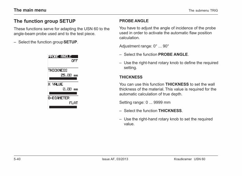
5-40 Issue AF, 03/2013 Krautkramer USN 60
The main menu
The function group SETUPThese functions serve for adapting the USN 60 to theangle-beam probe used and to the test piece.
– Select the function group SETUP.
PROBE ANGLE
You have to adjust the angle of incidence of the probeused in order to activate the automatic flaw positioncalculation.
Adjustment range: 0° ... 90°
– Select the function PROBE ANGLE.
– Use the right-hand rotary knob to define the requiredsetting.
THICKNESS
You can use this function THICKNESS to set the wallthickness of the material. This value is required for theautomatic calculation of true depth.
Setting range: 0 ... 9999 mm
– Select the function THICKNESS.
– Use the right-hand rotary knob to set the requiredvalue.
The submenu TRIG
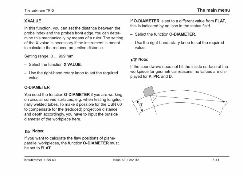
Krautkramer USN 60 Issue AF, 03/2013 5-41
The main menu
X VALUE
In this function, you can set the distance between theprobe index and the probe’s front edge. You can deter-mine this mechanically by means of a ruler. The settingof the X value is necessary if the instrument is meantto calculate the reduced projection distance.
Setting range: 0 ... 999 mm
– Select the function X VALUE.
– Use the right-hand rotary knob to set the requiredvalue.
O-DIAMETER
You need the function O-DIAMETER if you are workingon circular curved surfaces, e.g. when testing longitudi-nally welded tubes. To make it possible for the USN 60to compensate for the (reduced) projection distanceand depth accordingly, you have to input the outsidediameter of the workpiece here.
H Notes:
If you want to calculate the flaw positions of plane-parallel workpieces, the function O-DIAMETER mustbe set to FLAT.
If O-DIAMETER is set to a different value from FLAT,this is indicated by an icon in the status field.
– Select the function O-DIAMETER.
– Use the right-hand rotary knob to set the requiredvalue.
H Note:
If the soundwave does not hit the inside surface of theworkpiece for geometrical reasons, no values are dis-played for P, PR, and D.
The submenu TRIG
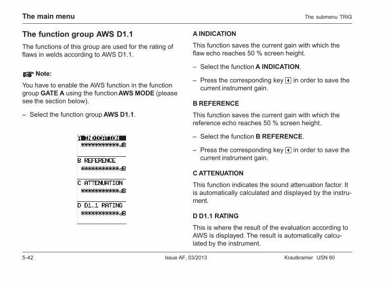
5-42 Issue AF, 03/2013 Krautkramer USN 60
The main menu
The function group AWS D1.1The functions of this group are used for the rating offlaws in welds according to AWS D1.1.
HHHHH Note:
You have to enable the AWS function in the functiongroup GATE A using the function AWS MODE (pleasesee the section below).
– Select the function group AWS D1.1.
A INDICATION
This function saves the current gain with which theflaw echo reaches 50 % screen height.
– Select the function A INDICATION.
– Press the corresponding key v in order to save thecurrent instrument gain.
B REFERENCE
This function saves the current gain with which thereference echo reaches 50 % screen height.
– Select the function B REFERENCE.
– Press the corresponding key v in order to save thecurrent instrument gain.
C ATTENUATION
This function indicates the sound attenuation factor. Itis automatically calculated and displayed by the instru-ment.
D D1.1 RATING
This is where the result of the evaluation according toAWS is displayed. The result is automatically calcu-lated by the instrument.
The submenu TRIG
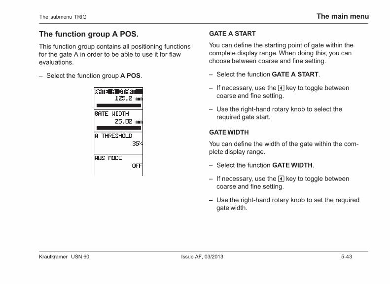
Krautkramer USN 60 Issue AF, 03/2013 5-43
The main menu
The function group A POS.This function group contains all positioning functionsfor the gate A in order to be able to use it for flawevaluations.
– Select the function group A POS.
The submenu TRIG
GATE A START
You can define the starting point of gate within thecomplete display range. When doing this, you canchoose between coarse and fine setting.
– Select the function GATE A START.
– If necessary, use the v key to toggle betweencoarse and fine setting.
– Use the right-hand rotary knob to select therequired gate start.
GATE WIDTH
You can define the width of the gate within the com-plete display range.
– Select the function GATE WIDTH.
– If necessary, use the v key to toggle betweencoarse and fine setting.
– Use the right-hand rotary knob to set the requiredgate width.
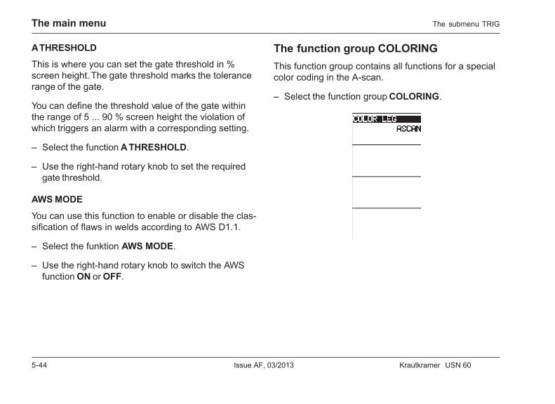
5-44 Issue AF, 03/2013 Krautkramer USN 60
The main menu
A THRESHOLD
This is where you can set the gate threshold in %screen height. The gate threshold marks the tolerancerange of the gate.
You can define the threshold value of the gate withinthe range of 5 ... 90 % screen height the violation ofwhich triggers an alarm with a corresponding setting.
– Select the function A THRESHOLD.
– Use the right-hand rotary knob to set the requiredgate threshold.
AWS MODE
You can use this function to enable or disable the clas-sification of flaws in welds according to AWS D1.1.
– Select the funktion AWS MODE.
– Use the right-hand rotary knob to switch the AWSfunction ON or OFF.
The function group COLORINGThis function group contains all functions for a specialcolor coding in the A-scan.
– Select the function group COLORING.
The submenu TRIG
Krautkramer USN 60 Issue AF, 03/2013 5-45
The main menu
COLOR LEG
For better orientation, the USN 60 can indicate the dif-ferent legs in different colors. In this connection, youcan choose between the color coding of the A-scanand the color coding of the background grid.The following options are available:
• ASCANThe A-scan is color coded
• GRIDThe background grid is color coded
• OFFThe legs are not color coded.
– Select the function COLOR LEG.
– Use the right-hand rotary knob to choose the re-quired option.
The submenu TRIG
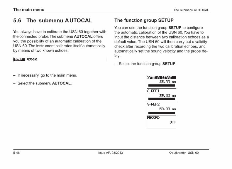
5-46 Issue AF, 03/2013 Krautkramer USN 60
The main menu
5.6 The submenu AUTOCAL
You always have to calibrate the USN 60 together withthe connected probe. The submenu AUTOCAL offersyou the possibility of an automatic calibration of theUSN 60. The instrument calibrates itself automaticallyby means of two known echoes.
– If necessary, go to the main menu.
– Select the submenu AUTOCAL.
The function group SETUPYou can use the function group SETUP to configurethe automatic calibration of the USN 60. You have toinput the distance between two calibration echoes as adefault value. The USN 60 will then carry out a validitycheck after recording the two calibration echoes, andautomatically set the sound velocity and the probe de-lay.
– Select the function group SETUP.
The submenu AUTOCAL

Krautkramer USN 60 Issue AF, 03/2013 5-47
The main menu
GATE A START
This function serves for positioning the gate on thecalibration echo.
– Select the function GATE A START.
– If necessary, use the v key to toggle betweencoarse and fine setting.
– Use the right-hand rotary knob to position the gate.
S-REF1
Set the material thickness of the thinner calibrationblock here.
– Select the function S-REF1.
– Use the right-hand rotary knob to set the requiredvalue.
S-REF2
Set the material thickness of the thicker calibrationblock here.
– Select the function S-REF2.
– Use the right-hand rotary knob to set the requiredvalue.
RECORD
This function serves for recording the current calibra-tion echo in the A gate.
– Select the function RECORD, the display willchange from OFF to S-REF1?.
– Press the v key next to RECORD in order to recordthe echo in the A gate as calibration echo. The dis-play changes to S-REF2?.
– If necessary, generate the 2nd calibration echo.
– Move the gate to the 2nd calibration echo.
– Press the v key next to RECORD again in order torecord the 2nd calibration echo, OFF is displayed.
An automatic calibration is carried out after theUSN 60 has calculated the input parameters andchecked the validity.
H Note:
Check the correct calibration by means of anotherecho, not used for the calibration but having a knownsound path.
The submenu AUTOCAL
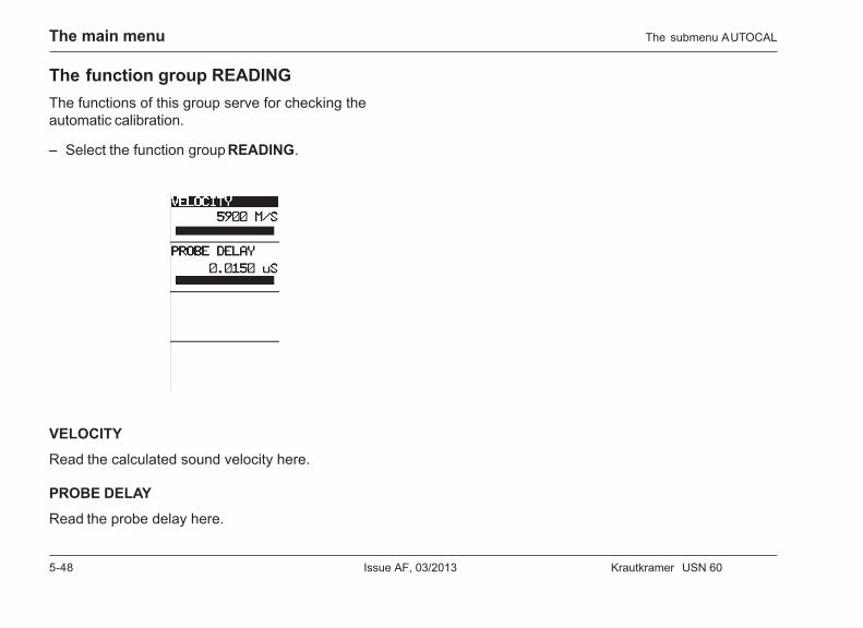
5-48 Issue AF, 03/2013 Krautkramer USN 60
The main menu
The function group READINGThe functions of this group serve for checking theautomatic calibration.
– Select the function group READING.
VELOCITY
Read the calculated sound velocity here.
PROBE DELAY
Read the probe delay here.
The submenu AUTOCAL
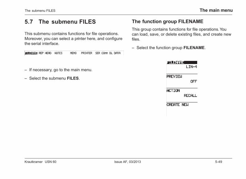
Krautkramer USN 60 Issue AF, 03/2013 5-49
The main menu
5.7 The submenu FILES
This submenu contains functions for file operations.Moreover, you can select a printer here, and configurethe serial interface.
– If necessary, go to the main menu.
– Select the submenu FILES.
The function group FILENAMEThis group contains functions for file operations. Youcan load, save, or delete existing files, and create newfiles.
– Select the function group FILENAME.
The submenu FILES
5-50 Issue AF, 03/2013 Krautkramer USN 60
The main menu
FILENAME
This is where you can select the files that you want toedit.
– Select the function FILENAME.
– Use the right-hand rotary knob to select therequired file.
PREVIEW
You can use this function to activate the file preview. Inthe file preview, additional information, saved togetherwith the file, is displayed on the screen.
H Note:
If the file preview is active, you have no access toother functions.
– Select the function PREVIEW.
– Use the right-hand rotary knob to choose the optionON in order to activate the preview.
ACTION
This function serves for loading, deleting, and editingsaved files. This is where you can select an action thatyou would like to carry out with the file. You have achoice between the following options:
• RECALLFor loading a saved file.
• SAVE EDITSFor editing a file.
• CLEARFor deleting a saved file.
– Select the function ACTION.
– Use the right-hand rotary knob to select therequired action.
– Press the corresponding v key in order to carry outthe action. A message in the menu bar prompts youto confirm the selected action.
– Press the h key in order to confirm the action.
The submenu FILES
Krautkramer USN 60 Issue AF, 03/2013 5-51
The main menu
H Note:
You have to confirm the selected action within five sec-onds. Otherwise the selection becomes invalid.
CREATE NEW
This function serves for creating new files. If youcreate a new file, you can choose between different filetypes:
• LINEARThe saved measured values are arranged in a rowand consecutively numbered.
• GRIDThe saved measured values are arranged in tabularform. The columns and rows are identified either bynumbers or by letters.
• CUSTOM LINEARThe saved measured values are arranged in a rowand can be given alphanumerical names.
– Select the function CREATE NEW.
– Activate the function using the v key next to it. Thebox for creating files appears.
– Select the required file type, and configure it.
– Select the function STORE to save the new file.
For information about saving files, please readchapter 8.
The submenu FILES
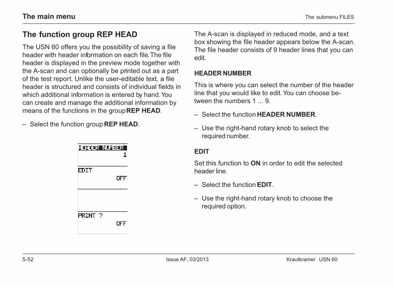
5-52 Issue AF, 03/2013 Krautkramer USN 60
The main menu
The function group REP HEADThe USN 60 offers you the possibility of saving a fileheader with header information on each file. The fileheader is displayed in the preview mode together withthe A-scan and can optionally be printed out as a partof the test report. Unlike the user-editable text, a fileheader is structured and consists of individual fields inwhich additional information is entered by hand. Youcan create and manage the additional information bymeans of the functions in the group REP HEAD.
– Select the function group REP HEAD.
The A-scan is displayed in reduced mode, and a textbox showing the file header appears below the A-scan.The file header consists of 9 header lines that you canedit.
HEADER NUMBER
This is where you can select the number of the headerline that you would like to edit. You can choose be-tween the numbers 1 ... 9.
– Select the function HEADER NUMBER.
– Use the right-hand rotary knob to select therequired number.
EDIT
Set this function to ON in order to edit the selectedheader line.
– Select the function EDIT.
– Use the right-hand rotary knob to choose therequired option.
The submenu FILES
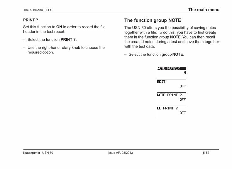
Krautkramer USN 60 Issue AF, 03/2013 5-53
The main menu
PRINT ?
Set this function to ON in order to record the fileheader in the test report.
– Select the function PRINT ?.
– Use the right-hand rotary knob to choose therequired option.
The function group NOTEThe USN 60 offers you the possibility of saving notestogether with a file. To do this, you have to first createthem in the function group NOTE. You can then recallthe created notes during a test and save them togetherwith the test data.
– Select the function group NOTE.
The submenu FILES

5-54 Issue AF, 03/2013 Krautkramer USN 60
The main menu
The A-scan is displayed in reduced mode, and a textbox showing the notes appears below the A-scan. Youcan create a maximum of seven notes.
NOTE NUMBER
This is where you can select the note that you wouldlike to edit. You can choose between the notes A ... G.
– Select the function NOTE NUMBER.
– Use the right-hand rotary knob to select therequired note.
EDIT
Set this function to ON in order to edit the selectednote.
– Select the function EDIT.
– Use the right-hand rotary knob to choose therequired option.
NOTE PRINT ?
Set this function to ON in order to record the list withthe notes in the test report.
– Select the function NOTE PRINT ?.
– Use the right-hand rotary knob to choose therequired option.
DL PRINT ?
Set this function to ON in order to record the Data Log-ger file in the test report.
– Select the function DL PRINT ?.
– Use the right-hand rotary knob to choose therequired option.
The submenu FILES
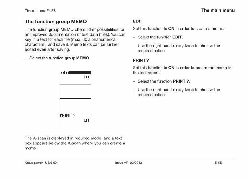
Krautkramer USN 60 Issue AF, 03/2013 5-55
The main menu
The function group MEMOThe function group MEMO offers other possibilities foran improved documentation of test data (files). You cankey in a text for each file (max. 80 alphanumericalcharacters), and save it. Memo texts can be furtheredited even after saving.
– Select the function group MEMO.
The A-scan is displayed in reduced mode, and a textbox appears below the A-scan where you can create amemo.
The submenu FILES
EDIT
Set this function to ON in order to create a memo.
– Select the function EDIT.
– Use the right-hand rotary knob to choose therequired option.
PRINT ?
Set this function to ON in order to record the memo inthe test report.
– Select the function PRINT ?.
– Use the right-hand rotary knob to choose therequired option.
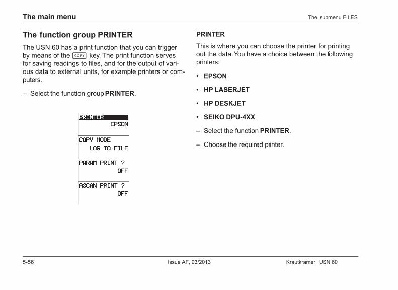
5-56 Issue AF, 03/2013 Krautkramer USN 60
The main menu
The function group PRINTERThe USN 60 has a print function that you can triggerby means of the c key. The print function servesfor saving readings to files, and for the output of vari-ous data to external units, for example printers or com-puters.
– Select the function group PRINTER.
The submenu FILES
PRINTER
This is where you can choose the printer for printingout the data. You have a choice between the followingprinters:
• EPSON
• HP LASERJET
• HP DESKJET
• SEIKO DPU-4XX
– Select the function PRINTER.
– Choose the required printer.
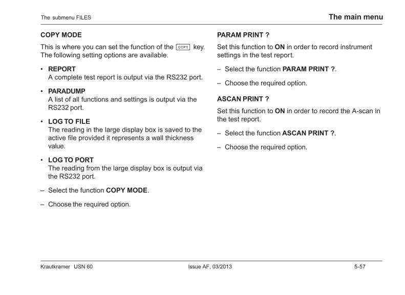
Krautkramer USN 60 Issue AF, 03/2013 5-57
The main menu
COPY MODE
This is where you can set the function of the c key.The following setting options are available.
• REPORTA complete test report is output via the RS232 port.
• PARADUMPA list of all functions and settings is output via theRS232 port.
• LOG TO FILEThe reading in the large display box is saved to theactive file provided it represents a wall thicknessvalue.
• LOG TO PORTThe reading from the large display box is output viathe RS232 port.
– Select the function COPY MODE.
– Choose the required option.
PARAM PRINT ?
Set this function to ON in order to record instrumentsettings in the test report.
– Select the function PARAM PRINT ?.
– Choose the required option.
ASCAN PRINT ?
Set this function to ON in order to record the A-scan inthe test report.
– Select the function ASCAN PRINT ?.
– Choose the required option.
The submenu FILES
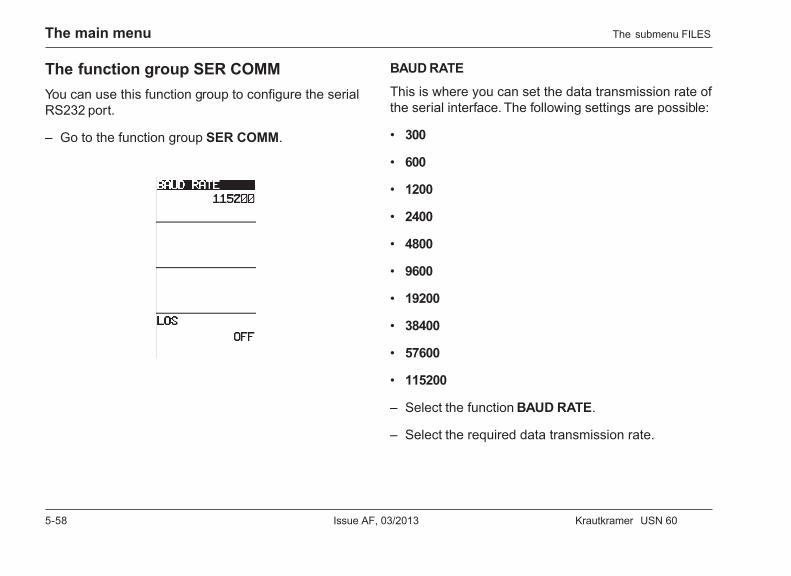
5-58 Issue AF, 03/2013 Krautkramer USN 60
The main menu
The function group SER COMMYou can use this function group to configure the serialRS232 port.
– Go to the function group SER COMM.
BAUD RATE
This is where you can set the data transmission rate ofthe serial interface. The following settings are possible:
• 300
• 600
• 1200
• 2400
• 4800
• 9600
• 19200
• 38400
• 57600
• 115200
– Select the function BAUD RATE.
– Select the required data transmission rate.
The submenu FILES
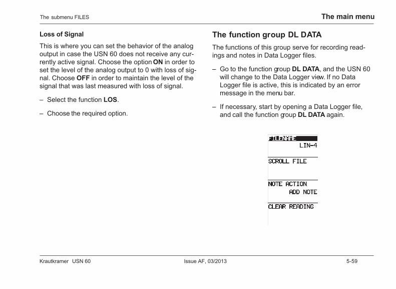
Krautkramer USN 60 Issue AF, 03/2013 5-59
The main menu
Loss of Signal
This is where you can set the behavior of the analogoutput in case the USN 60 does not receive any cur-rently active signal. Choose the option ON in order toset the level of the analog output to 0 with loss of sig-nal. Choose OFF in order to maintain the level of thesignal that was last measured with loss of signal.
– Select the function LOS.
– Choose the required option.
The function group DL DATAThe functions of this group serve for recording read-ings and notes in Data Logger files.
– Go to the function group DL DATA, and the USN 60will change to the Data Logger view. If no DataLogger file is active, this is indicated by an errormessage in the menu bar.
– If necessary, start by opening a Data Logger file,and call the function group DL DATA again.
The submenu FILES
5-60 Issue AF, 03/2013 Krautkramer USN 60
The main menu
FILENAME
This is where you select a previously created DataLogger file in order to edit it.
– Select the function FILENAME.
– Select the required file.
SCROLL FILE
You can use this function to select a measuring pointof the Data Logger file in order to edit it.
– Select the function SCROLL FILE.
– Select the required measuring point.
NOTE ACTION
You need the function NOTE ACTION in order to savenotes on the measuring point. It presents the followingoptions:
• ADD NOTEFor inserting a note on a measuring point.
• DISPLAY NOTESDisplays the texts of all notes that are available.
The submenu FILES
• DELETE NOTEFor deleting notes on a measuring point.
– Select the function NOTE ACTION.
– Select the required action.
CLEAR READING
This function serves for clearing a saved reading.
– Select the function CLEAR READING.
– Activate the function using the corresponding v key.
– Use the h key to confirm the clearing of thereading.
Krautkramer USN 60 Issue AF, 03/2013 6-1
The test menu 6
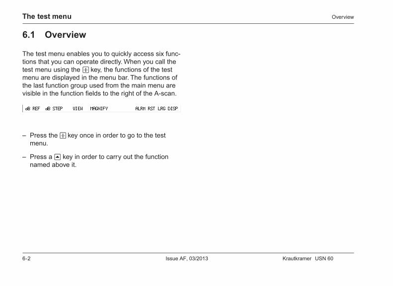
6-2 Issue AF, 03/2013 Krautkramer USN 60
The test menu Overview
6.1 Overview
The test menu enables you to quickly access six func-tions that you can operate directly. When you call thetest menu using the w key, the functions of the testmenu are displayed in the menu bar. The functions ofthe last function group used from the main menu arevisible in the function fields to the right of the A-scan.
– Press the w key once in order to go to the testmenu.
– Press a u key in order to carry out the functionnamed above it.
Krautkramer USN 60 Issue AF, 03/2013 6-3
The test menuThe functions
6.2 The functions
db REFYou can choose whether the amplitude of an echo isindicated in % screen height or as a difference in dBwith regard to a reference echo. You can use the func-tion dB REF to define the current echo in the gate asreference echo. The amplitude of all other echoes ofthe gate is then indicated as dB difference with regardto the reference echo in the gain field.
– Select the function dB REF in order to store anecho as reference echo.
– Select the function dB REF again in order to displaythe amplitude in % screen height again.
dB STEPYou can set the gain by means of a certain step sizethat you can select by means of the function dB STEP.There are six steps available:
• User-defined
• 6.0 dB
• 2.0 dB
• 1.0 dB
• 0.5 dB
• 0.1 dB
• LOCK (locked)
The current step size is indicated in the top right cor-ner of the gain field.
H Note:
For information on how to set the user-defined stepsize, please read chapter 5.3.
6-4 Issue AF, 03/2013 Krautkramer USN 60
The test menu
H Note:
If the option LOCK is set, you cannot vary the gain.
– Press the u key below the function dB STEPrepeatedly in order to select the required step size.The current choice is indicated in the top rightcorner of the gain field.
VIEWThe USN 60 enables you to change between differentdisplay views. Information about data memory alloca-tion and Data Logger may also be displayed next tothe A-scan.
– Press the u key below the function VIEW once inorder to obtain information about the data memoryallocation.
– Press the u key once again in order to go to theData Logger view.
H Note:
For information on how to use the Data Logger, pleaseread chapter 8.
The functions
Krautkramer USN 60 Issue AF, 03/2013 6-5
The test menu
MAGNIFYThis function serves for the zoomed representation ofa selected gate. The range is expanded until the gatefills covers the complete display width.
If the function MAGNIFY is activated, a magnifier iconis displayed in the status field.
– Select the function MAGNIFY for the zoomed repre-sentation of a gate.
ALARM RSTYou can acknowledge alarms by hand. The alarm signalis switched off and is available for indicating newalarms.
H Note:
You can acknowledge the alarm by hand only if thesetting LATCHED is selected for the function MODE.
– Press the u key below the function ALARM RST inorder to acknowledge the alarm.
The functions
6-6 Issue AF, 03/2013 Krautkramer USN 60
The test menu
LRG DISPYou can zoom the display of one of the four readingsfrom the small display boxes in the large display box.The value in the large display box can then be re-corded in the Data Logger, or be output to a peripheralunit.
– Press the u key below the function LRG DISP re-peatedly until the required value is displayed in thelarge display box.
The functions
Krautkramer USN 60 Issue AF, 03/2013 7-1
Operation 7
7-2 Issue AF, 03/2013 Krautkramer USN 60
Operation Setting the gain
7.1 Setting the gain
You can amplify echoes in order to display them at therequired height on the screen. To do this, you can usethe left-hand rotary knob to set the required gain. Thesetting is carried out step by step according to the stepselected in the function db STEP. The current gain isdisplayed in the top left-hand corner of the gain field.
H Note:
You cannot vary the gain of the echoes if you havechosen the option LOCK for the function dB STEP. Thecurrent choice for the function dB STEP may be seenat the top right of the gain field.
– Use the left-hand rotary knob to set the requiredgain.
7.2 Displaying the screen scale
If required, the A-scan can be provided with a scale.The scale is displayed in the X-axis of the A-scan andgives you in this way an overview of the echo posi-tions. You have a choice between a dimensionless ten-division scale and a scale showing the actual positionof the echoes. You can set the units of this scale b ymeans of the function UNITS in the function groupREGIONAL from the submenu BASIC.
– Press the w key twice in order to display the dimen-sionless scale.
– Press the w key a third time in order to display thescale with the selected units.

Krautkramer USN 60 Issue AF, 03/2013 7-3
OperationCalibrating the USN 60
7.3 Calibrating the USN 60
Calibrating the display rangeBefore using the USN 60, the instrument has to becalibrated: The sound velocity and the calibration rangehave to be set and the probe delay taken into consider-ation depending on the material and dimensions of thetest piece. In addition, the test sensitivity must be setaccording to the specified requirements.
A Attention:
In order to be able to operate the USN 60 safely andeffectively, adequate training in ultrasonic test technol-ogy is required.
The calibration ensures that
• the complete thickness of the test piece is displayed,
• the distance from the flaw or from the backwall ofthe test piece can be determined by means of thehorizontal echo position or displayed digitally,
• all flaws are indicated that have to be detected ac-cording to the test specifications,
• a flaw evaluation can be carried out by way of com-parison with known reflectors.
H Note:
Use a calibration block made of the same material andhaving the same temperature as your test piece for allcalibration procedures.
The following examples show three main methods ofultrasonic testing:
• Scanning with a straight-beam probe,
• Vertical scanning with a dual-element probe,
• Inclined scanning with an angle-beam probe(transverse waves).
7-4 Issue AF, 03/2013 Krautkramer USN 60
Operation
In all calibration procedures, you have to
• set pulser and receiver according to the test job and
• decide before calibrating on whether the measure-ment should be carried out in the flank or in the peakmode (function DETECTION).
As long as the echoes to be evaluated show a clearmaximum amplitude, select the peak mode.
Basic setting
Before calibrating the USN 60, you have to define thefollowing basic settings:
Function SettingPROBE DELAY 0.000 µsDISPLAY DELAY 0.000 µsMASTER LOCK OFFPRF MODE AUTO LOWDUAL ONREJECT 0 %TCG MODE OFF
Calibration with straight-beam probes
Sound velocity is known, no delay line
– Set the sound velocity on by means of the functionVELOCITY, or use the function MATERIAL to selecta corresponding test material.
– Position the A gate on one of the echoes.
– Set the function PROBE DELAY so that the correctvalue for SA is indicated in the display box.
Example:
Carry out the calibration for the calibration range of 100mm on the calibration block K1 (thickness 25 mm) ly-ing flatwise.
– Set the function RANGE to 100 mm.
– Use the function VELOCITY to set the known soundvelocity (5920 m/s) .
– Position the gate on the first calibration echo from25 mm.
– Set the function PROBE DELAY so thatSA = 25mm is displayed in the display box.
Calibrating the USN 60
Krautkramer USN 60 Issue AF, 03/2013 7-5
Operation
The display range is now calibrated for the describedtask setting.
Sound velocity is unknown,no delay line
A Attention:
Beware of node errors with flank setting!
– Set the gates so that the first echo in the A gate andthe second echo in the B gate are evaluated.
– Set the four display boxes for readings so that youcan read the sound path in the gates A and B, aswell as the sound path difference between the gatesA and B.
– Vary the sound velocity by means of the functionVELOCITY until the displayed sound path differencecorresponds to the actual thickness of the testpiece. The gate parameters may possibly have to bereadjusted.
– Increase the function PROBE DELAY until thecorrect sound path is displayed for the echo in theA gate.
Example:
Carry out the calibration on a 25 mm thick calibrationblock for a calibration range of 100 mm.
– Set the function RANGE to 100 mm.
– Set the function DISPLAY DELAY to 0.000 µs.
– If possible, use the function VELOCITY to set anapproximative value for the sound velocity.
– Set the gate so that the first echo in the A gate andthe second echo in the B gate are evaluated.
– Set the sound velocity by means of the functionVELOCITY so that the sound path difference ofSA = 25mm is displayed.
– Increase the function PROBE DELAY until thecorrect sound path for the echo is displayed in theA gate.
Calibrating the USN 60
7-6 Issue AF, 03/2013 Krautkramer USN 60
Operation
Straight-beam probe with fixed delay line
Calibration using straight-beam probes equipped with alarger delay line corresponds largely to the calibrationfor straight-beam probes having only the protectionlayer as delay line, as described above.
Other than the procedure described above, you have todefine the following settings at first:
– Set the functions DISPLAY DELAY and PROBEDELAY to 0 µs.
– Set the function PROBE DELAY so that the first in-terface echo is at the scale zero.
– Set the function RANGE so that the first interfaceecho and at least also the first backwall echo appearbefore the second interface echo with known soundvelocity, or that at least two backwall echoes appearbefore the second interface echo with unknownsound velocity.
– Continue in this case as in the case described previ-ously.
Calibration with angle-beam probes
Sound velocity is known
In this case, it’s only necessary to have the echo froma known reflector with a known distance available, e.g.the circular arc of the calibration block K1, K2.
– Set the sound velocity by means of the functionVELOCITY, or use the function MATERIAL to selecta corresponding test material.
– Position the A gate on the first echo.
– Set the function PROBE DELAY so that the correctvalue for SA is displayed in the display box.
Example:
Calibration of the100mm range for steeltrans on the cali-bration block K2.
– Set the sound velocity (3255 m/s) by means of thefunction VELOCITY, or select STEEL MILD S inthe function MATERIAL.
– Set the function RANGE to 100 mm.
– Set the functions DISPLAY DELAY and PROBEDELAY to 0 µs.
Calibrating the USN 60

Krautkramer USN 60 Issue AF, 03/2013 7-7
Operation
– Couple the probe, and peak the first echo from the25mm radius of K2.
– Set the A gate on the first quadrant echo.
– Set the function PROBE DELAY so thatSA = 25mm is displayed in the display box.
The display range is now calibrated. You can now enterthe values for PROBE ANGLE, THICKNESS andX VALUE for the measurement.
Sound velocity is unknown
In this case, you need a calibration block made of thesame material as the test piece for the calibration. Asemi-cylinder is suitable for this.
Couple the probe to the plane of section of the semi-cylinder having the radius R, and peak the first echofrom the semi-circle. This produces an echo sequencefrom the sound paths R, 3R, 5R, etc.
Use these echoes for the calibration just like the back-wall echoes from a plane-parallel calibration block inthe vertical scanning described above.
Example:
Calibration on a semi-cylinder having the radiusR = 50 mm to a test range of 200 mm.
– Set the function RANGE to 200 mm.
– Set the functions DISPLAY DELAY and PROBEDELAY to 0 µs.
– Couple the probe, and peak the echoes.
– Set the gate in such a way that the first quadrantecho (50 mm sound path) is evaluated in the A gateand the second quadrant echo (150 mm sound path)in the B gate.
– Set the sound velocity by means of the functionVELOCITY so that SAB = 100mm is displayed inthe display box.
– Position the A gate on an echo.
– Set the function PROBE DELAY so thatSA = 50mm is displayed in the display box.
The calibration is now completed.
Calibrating the USN 60
7-8 Issue AF, 03/2013 Krautkramer USN 60
Operation
Calibration with dual-element probesDual-element probes are mainly used for wall thicknessmeasurements. When using these probes, please ob-serve the following special aspects:
Detection mode flank
Most dual-element probes have a roof angle (trans-ducer elements orientated at an angle to the test sur-face). This produces mode conversions at the soundentry and at reflections from the backwall that maylead to very rugged and broad echoes. You shouldtherefore always select FLANK as DETECTION.
In order to obtain a maximum rate of rise of the flank,which allows for an increased measuring accuracy, youcan use the reject function if necessary. Please ob-serve the notes on the functions ENERGY, VOLTAGEand WIDTH in this regard.
V-path error
There is a v-shaped sound path from the pulser via thereflection from the backwall to the receiving transducerelement with dual-element probes. This V-path error af-fects the measuring accuracy. You should therefore se-lect two wall thicknesses that cover the expected wall
thickness measuring range for the calibration. This en-ables to largely compensate for the V-path error.
Higher sound velocity
Due to the V-path error, a higher sound velocity thanthat of the test material results especially when cali-brating on small thicknesses. This is typical of dual-element probes and serves for the compensation of theV-path error.
Because of the effect described above, there is a dropin the echo amplitude with small wall thicknesses thathas to be taken into account, especially in caseswhere thickness is < 2 mm .
A stepped block showing different wall thicknesses isrequired for the calibration. The wall thicknesses mustbe selected in such a way that they cover the mea-sured values to be expected.
– Set the function DUAL to ON.
– Set the function RANGE according to the test joband the probe used.
– Set the function DETECTION to FLANK.
Calibrating the USN 60
Krautkramer USN 60 Issue AF, 03/2013 7-9
Operation
– Couple the probe to the thinner calibration block, andpeak the echoes.
– Set the flank as steep as possible by varying thegain.
– Position the A gate on the first echo.
– Set the function PROBE DELAY so that the correctvalue is displayed for SA in the display box.
– Couple the probe to the thicker calibration block, andpeak the echoes.
– Set the flank as steep as possible by varying thegain.
– Position the A gate on the first echo.
– Set the sound velocity by means of the functionVELOCITY so that the correct value is displayed forSA in the display box.
– Repeat these two steps until the two calibrationsteps are correctly displayed.
Automatic calibrationWith its submenu AUTOCAL, the USN 60 enables youto carry out an automatic two-step calibration. To dothis, you have to record two calibration echoes fromknown calibration steps. After this, the USN 60 usesthe two calibration echoes to determine the currentprobe delay and the sound velocity in the test material.
– If necessary, go to the main menu and then to thesubmenu AUTOCAL.
– Select the function group SETUP.
Setting the calibration steps
– Select the function S-REF1.
– Use the right-hand rotary knob to set the materialthickness of the thinner calibration block.
– Go to the function S-REF2.
– Use the right-hand rotary knob to set the materialthickness of the thicker calibration block.
Calibrating the USN 60
7-10 Issue AF, 03/2013 Krautkramer USN 60
Operation
Recording the calibration echo
– Couple the probe to a calibration block having aknown material thickness.
– Select the function GATE A START, and position theA gate on the first echo.
– Go to the function RECORD, and choose the optionS-REF1?.
– Press the v key next to the function RECORD inorder to record the calibration echo for the firstcalibration step. The option S-REF2? appears.
– Select the function GATE A START, and position theA gate on the second echo.
– Go to the function RECORD.
– Press the v key next to the function RECORD inorder to record the calibration echo for the secondcalibration step. OFF appears, which means that thecalibration is completed.
Checking the calibration
– Select the function group READING.
– Read the determined sound velocity in the test ma-terial in the function VELOCITY.
– Read the determined probe delay in the functionPROBE DELAY.
H Note:
Check the correct calibration by means of anotherecho, not used for the calibration but having a knownsound path.
Calibrating the USN 60
Krautkramer USN 60 Issue AF, 03/2013 7-11
Operation
Preparing for the wall thicknessmeasurementThe USN 60 must be calibrated for the material to betested in order to produce correct readings.
H Note:
Use a calibration block having a known thickness,made of the same material, and having the same tem-perature as your test piece for all calibration proce-dures.
Start by calibrating the A-scan display as shown in thepreceding section. Carry out the following basic set-tings:
• LOGIC: POSITIVE, NEGATIVE or MEASURE
• DETECTION: depending on the application.
Calibrating the sensitivity (dB REF)
The function dB REF is of great help for the sensitivitycalibration. The function dB REF allows you to store areference echo as a basis for your measurements andthe amplitude evaluation. dB differences between the
amplitudes of any chosen echo and the stored echoare directly digitally displayed as AdBR in the displaybox.
– Couple the probe and peak the reference echo.
– Vary the gain so that the echo reaches the requiredheight.
– Position the A gate on the reference echo. It must bethe highest echo in the gate.
– If necessary, go to the test menu, and press the ukey below dB REF. This stores the reference echo.Press the key one more time in order to reset thevalue again.
Reading the dB difference
– Set the function AMPLITUDE to dB THRESHOLD.
– Position the gate on the required echo.
The difference value is displayed in the display box. Itindicates the amount of dB by which the flaw echo isinferior or superior to the reference echo.
Calibrating the USN 60
7-12 Issue AF, 03/2013 Krautkramer USN 60
Operation
7.4 Wall thickness measurement
The USN 60 enables you to measure wall thicknessesor distances in the easiest way. The measured value isdirectly displayed. Depending on the task setting, oneof the two following methods of measurement is ap-plied:
• Measurement up to the first echo, e.g. with corrosionmapping using a dual-element probe.
• Measurement of the multi-echo sequence using asingle-element probe with good test surfaces oneither side of the test piece.
Preparations
– Select the probe.
– Set the function READING to on.
– Use the function DETECTION to select themeasurement mode.
– Calibrate the A-scan display.
– Calibrate the USN 60 for the selected probe and themeasurement mode (please see precedingsection).
Wall thickness measurement
– Clean the test piece surface from any dirt and looseparts.
– Apply couplant to the surface of the test piece.
– Place the probe on the surface applying uniform,slight pressure.
– Observe the A-scan display and the reading SA, andwait until the measured-value display is stable.
– Set the maximum echo amplitude.
– Read the measured value.
H Note:
You can save the displayed reading to Data Logger ortransfer it to other units via the RS232 port.
Wall thickness measurement

Krautkramer USN 60 Issue AF, 03/2013 7-13
Operation
7.5 Advanced functions
The USN 60 is equipped with a number of advancedfunctions. These functions enable the proficient inspec-tor to use the USN 60 for demanding applications.
Noise suppression (NSE IMMN)During automatic scanning of test pieces, gate alarmsare often triggered by interference pulses or reflectorshaving an uncritical size. To avoid such false alarms,the USN 60 provides you with the noise suppressionfunction.
With an active noise suppression, not every gate viola-tion triggers an alarm. An alarm is only triggered if acertain number of gate violations occurs within a speci-fied number of transmitter cycles. Other than realflaws, most interference pulses do not meet this re-quirement and do not therefore trigger any gate alarm.
You can define for yourself both the number of the nec-essary gate violations and the number of the transmit-ter cycles observed.
H Note:
The gate violations do not have to follow immediatelyafter one another, they only have to take place withinthe transmitter cycles observed.
– If necessary, go to the main menu and, after that, tothe submenu GATES.
– Select the function group NSE IMMN.
– Select the function ALARM SELECT.
– Use the right-hand rotary knob to select aTTL output in order to set its noise suppression.
– Select the function WINDOW.
– Use the right-hand rotary knob to set the total num-ber of transmitter cylces observed. You can set thenumber of transmitter cycles from 2 to 16 cycles.
– Select the function COUNT.
– Use the right-hand rotary knob to set the number ofgate violations.
Advanced functions
7-14 Issue AF, 03/2013 Krautkramer USN 60
Operation
Using Smart ViewThe USN 60 generates usually more A-scans than canbe displayed on the unit. The choice of the displayedA-scans from the raw data is made at random in thisconnection. With an active function Smart View, theUSN 60 analyzes the raw data and displays theA-scans showing the highest echo indications. In thisregard, the relevance of the echoes refers to the read-ing displayed in the large display box.
– If necessary, go to the main menu and, after that, tothe submenu BASIC.
– Select the function group CONFIG.
– Select the function ASCAN MODE.
– Use the right-hand rotary knob to select therequired display mode.
Example:
The value A%A (amplitude in the A gate in % screenheight) is displayed in the large display box, and an op-tion SMARTVIEW is selected. The USN 60 will nowfilter the A-scan showing the highest amplitude in theA gate out of the raw data. This A-scan is displayed.
H Note:
If the value of an amplitude is displayed in the largedisplay box, the USN 60 takes the highest amplitudeinto consideration for the option SMARTVIEW. If a wallthickness is displayed in the large display box, thenthe USN 60 takes the smallest wall thickness into con-sideration for the option SMARTVIEW.
Advanced functions
Krautkramer USN 60 Issue AF, 03/2013 7-15
Operation
Analog display modeIn spite of a digital screen display, the USN 60 offersyou the possibility of utilizing well-proven advantagesof the analog display. The function ASCAN ENHANCEenables you to select an echo display mode on thescreen so that analog effects are simulated.
The option SPARKLE enables to represent intensityvariations the way they occur with an analog displaydue to different speeds of the electron beam, e.g. atRF nodes or echo peaks, as well as on the baseline.
If the option BASELINE BREAK is chosen, the valleysbetween the half-waves of an echo are drawn up to thebaseline.
– If necessary, go to the main menu and, after that, tothe submenu BASIC.
– Select the function group CONFIG.
– Select the function ASCAN ENHANCE.
– Use the right-hand rotary knob to select therequired display mode.
Advanced functions
7.6 Rating of welds according toAWS D1.1
The rating of flaws in welds according to the AWS D1.1specifications is based on an evaluation of the signalamplitude. In this process, the echo amplitude of theflaw echo is compared with the echo amplitude of aknown reference reflector. In addition, the sound at-tenuation in the workpiece is also taken into consider-ation. The result is a dB value which is called flaw rat-ing. The flaw rating D is calculated according to theformula:
D = A - B - C
with:
• A = Indication (in dB)Absolute instrument gain with which the maximumflaw echo is at 50 % (± 5 %) echo height.
• B = Reference (in dB)Absolute instrument gain with which the maximumreference echo (1.5 mm side-drilled hole from thereference block 1) is at 50 % (± 5 %) echo height.
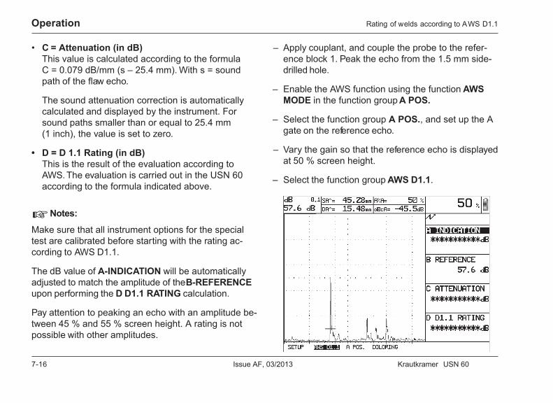
7-16 Issue AF, 03/2013 Krautkramer USN 60
Operation
• C = Attenuation (in dB)This value is calculated according to the formulaC = 0.079 dB/mm (s – 25.4 mm). With s = soundpath of the flaw echo.
The sound attenuation correction is automaticallycalculated and displayed by the instrument. Forsound paths smaller than or equal to 25.4 mm(1 inch), the value is set to zero.
• D = D 1.1 Rating (in dB)This is the result of the evaluation according toAWS. The evaluation is carried out in the USN 60according to the formula indicated above.
H Notes:
Make sure that all instrument options for the specialtest are calibrated before starting with the rating ac-cording to AWS D1.1.
The dB value of A-INDICATION will be automaticallyadjusted to match the amplitude of the B-REFERENCEupon performing the D D1.1 RATING calculation.
Pay attention to peaking an echo with an amplitude be-tween 45 % and 55 % screen height. A rating is notpossible with other amplitudes.
– Apply couplant, and couple the probe to the refer-ence block 1. Peak the echo from the 1.5 mm side-drilled hole.
– Enable the AWS function using the function AWSMODE in the function group A POS.
– Select the function group A POS., and set up the Agate on the reference echo.
– Vary the gain so that the reference echo is displayedat 50 % screen height.
– Select the function group AWS D1.1.
Rating of welds according to AWS D1.1
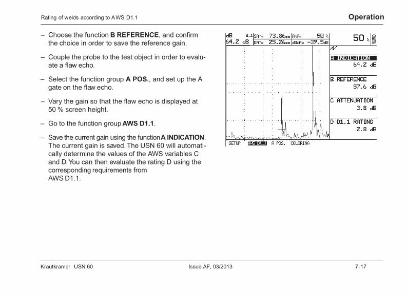
Krautkramer USN 60 Issue AF, 03/2013 7-17
Operation
– Choose the function B REFERENCE, and confirmthe choice in order to save the reference gain.
– Couple the probe to the test object in order to evalu-ate a flaw echo.
– Select the function group A POS., and set up the Agate on the flaw echo.
– Vary the gain so that the flaw echo is displayed at50 % screen height.
– Go to the function group AWS D1.1.
– Save the current gain using the function A INDICATION.The current gain is saved. The USN 60 will automati-cally determine the values of the AWS variables Cand D. You can then evaluate the rating D using thecorresponding requirements fromAWS D1.1.
Rating of welds according to AWS D1.1

7-18 Issue AF, 03/2013 Krautkramer USN 60

Krautkramer USN 60 Issue AF, 03/2013 8-1
Saving data 8
8-2 Issue AF, 03/2013 Krautkramer USN 60
Saving data Data sets, Data Logger
8.1 Data sets, Data Logger
The USN 60 provides convenient ways of saving andmanaging data. It offers you two types of data storage,viz. data set files and Data Logger files.
Data sets serve for saving A-scans and for recordingthe pertinent instrument settings. The Data Logger en-ables you to save a reading for every measurementlocation of a test job.
Additional information is stored for the two file types inthe form of file header and memo text. This additionalinformation is displayed in the preview mode conse-quently allowing you to specifically select the requiredfile. You should create the additional information beforesaving a file. You can nevertheless edit the additionalinformation later on.
All data saved to the USN 60 are maintained even ifyou interrupt the unit’s power supply.
You can :
• save the files,
• delete them,
• load them,
• selectively transfer them to peripheral units,
• output them via a PC or a printer.
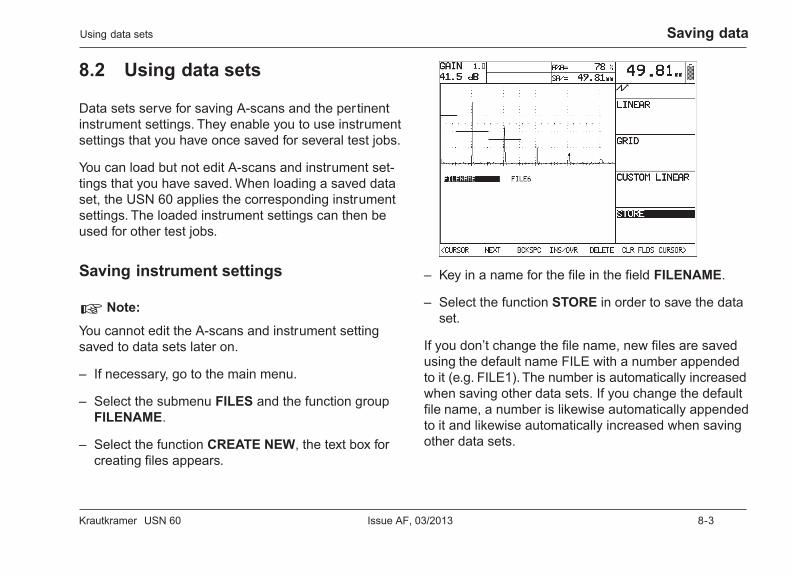
Krautkramer USN 60 Issue AF, 03/2013 8-3
Saving dataUsing data sets
8.2 Using data sets
Data sets serve for saving A-scans and the pertinentinstrument settings. They enable you to use instrumentsettings that you have once saved for several test jobs.
You can load but not edit A-scans and instrument set-tings that you have saved. When loading a saved dataset, the USN 60 applies the corresponding instrumentsettings. The loaded instrument settings can then beused for other test jobs.
Saving instrument settings
H Note:
You cannot edit the A-scans and instrument settingsaved to data sets later on.
– If necessary, go to the main menu.
– Select the submenu FILES and the function groupFILENAME.
– Select the function CREATE NEW, the text box forcreating files appears.
– Key in a name for the file in the field FILENAME.
– Select the function STORE in order to save the dataset.
If you don’t change the file name, new files are savedusing the default name FILE with a number appendedto it (e.g. FILE1). The number is automatically increasedwhen saving other data sets. If you change the defaultfile name, a number is likewise automatically appendedto it and likewise automatically increased when savingother data sets.
8-4 Issue AF, 03/2013 Krautkramer USN 60
Saving data
8.3 Using the Data Logger
The Data Logger helps you to save and manage yourreadings. You can define different test jobs and savenumerous readings at defined measurement locationsto the Data Logger. The Data Logger file therefore rep-resents the test job and helps you to quickly orientatewithin the test job.
In addition, the Data Logger enables you to save sev-eral notes on every reading. You can create the notesyourself according to your individual requirements anduse them for evaluating the measurement results.
You can save the following by means of the DataLogger:
• the current readings,
• the current instrument settings,
• the position of the measurement location,
• evaluating notes on every measurement result.
Creating a Data Logger fileBefore you’re able to save readings by means of theData Logger, you have to create a corresponding filefirst, and save it to the instrument. Saved files can beloaded, edited, or deleted at a later date.
– If necessary, go to the main menu.
– Select the submenu FILES and the function groupFILENAME.
– Set the function ACTION to SAVE EDITS.
– Select the function CREATE NEW. The text box andthe functions for creating files appear.
Using the Data Logger
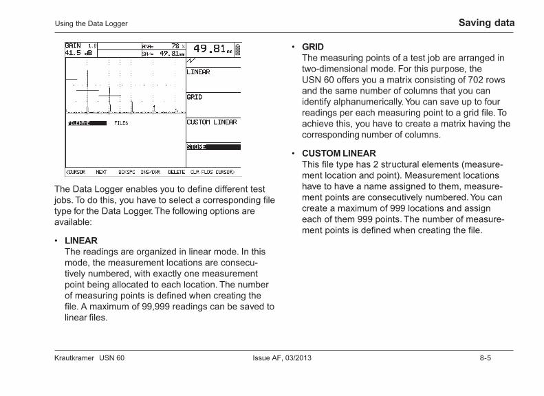
Krautkramer USN 60 Issue AF, 03/2013 8-5
Saving data
The Data Logger enables you to define different testjobs. To do this, you have to select a corresponding filetype for the Data Logger. The following options areavailable:
• LINEARThe readings are organized in linear mode. In thismode, the measurement locations are consecu-tively numbered, with exactly one measurementpoint being allocated to each location. The numberof measuring points is defined when creating thefile. A maximum of 99,999 readings can be saved tolinear files.
• GRIDThe measuring points of a test job are arranged intwo-dimensional mode. For this purpose, theUSN 60 offers you a matrix consisting of 702 rowsand the same number of columns that you canidentify alphanumerically. You can save up to fourreadings per each measuring point to a grid file. Toachieve this, you have to create a matrix having thecorresponding number of columns.
• CUSTOM LINEARThis file type has 2 structural elements (measure-ment location and point). Measurement locationshave to have a name assigned to them, measure-ment points are consecutively numbered. You cancreate a maximum of 999 locations and assigneach of them 999 points. The number of measure-ment points is defined when creating the file.
Using the Data Logger
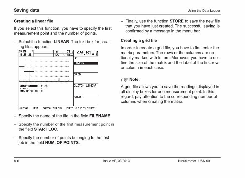
8-6 Issue AF, 03/2013 Krautkramer USN 60
Saving data
Creating a linear file
If you select this function, you have to specify the firstmeasurement point and the number of points.
– Select the function LINEAR. The text box for creat-ing files appears.
– Specify the name of the file in the field FILENAME.
– Specify the number of the first measurement point inthe field START LOC.
– Specify the number of points belonging to the testjob in the field NUM. OF POINTS.
– Finally, use the function STORE to save the new filethat you have just created. The successful saving isconfirmed by a message in the menu bar.
Creating a grid file
In order to create a grid file, you have to first enter thematrix parameters. The rows or the columns are op-tionally marked with letters. Moreover, you have to de-fine the size of the matrix and the label of the first rowor column in each case.
H Note:
A grid file allows you to save the readings displayed inall display boxes for one measurement point. In thisregard, pay attention to the corresponding number ofcolumns when creating the matrix.
Using the Data Logger
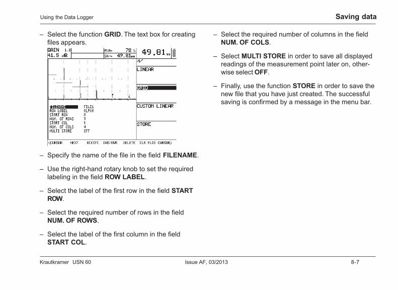
Krautkramer USN 60 Issue AF, 03/2013 8-7
Saving data
– Select the function GRID. The text box for creatingfiles appears.
– Specify the name of the file in the field FILENAME.
– Use the right-hand rotary knob to set the requiredlabeling in the field ROW LABEL.
– Select the label of the first row in the field STARTROW.
– Select the required number of rows in the fieldNUM. OF ROWS.
– Select the label of the first column in the fieldSTART COL.
– Select the required number of columns in the fieldNUM. OF COLS.
– Select MULTI STORE in order to save all displayedreadings of the measurement point later on, other-wise select OFF.
– Finally, use the function STORE in order to save thenew file that you have just created. The successfulsaving is confirmed by a message in the menu bar.
Using the Data Logger
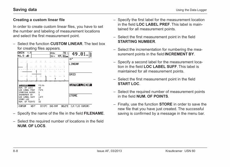
8-8 Issue AF, 03/2013 Krautkramer USN 60
Saving data
Creating a custom linear file
In order to create custom linear files, you have to setthe number and labeling of measurement locationsand select the first measurement point.
– Select the function CUSTOM LINEAR. The text boxfor creating files appears.
– Specify the name of the file in the field FILENAME.
– Select the required number of locations in the fieldNUM. OF LOCS.
– Specify the first label for the measurement locationin the field LOC LABEL PREF. This label is main-tained for all measurement points.
– Select the first measurement point in the fieldSTARTING NUMBER.
– Select the incrementation for numbering the mea-surement points in the field INCREMENT BY.
– Specify a second label for the measurement loca-tion in the field LOC LABEL SUFF. This label ismaintained for all measurement points.
– Select the first measurement point in the fieldSTART LOC.
– Select the required number of measurement pointsin the field NUM. OF POINTS.
– Finally, use the function STORE in order to save thenew file that you have just created. The successfulsaving is confirmed by a message in the menu bar.
Using the Data Logger
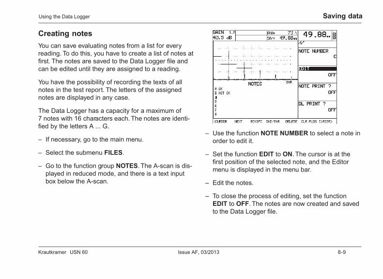
Krautkramer USN 60 Issue AF, 03/2013 8-9
Saving data
Creating notesYou can save evaluating notes from a list for everyreading. To do this, you have to create a list of notes atfirst. The notes are saved to the Data Logger file andcan be edited until they are assigned to a reading.
You have the possibility of recording the texts of allnotes in the test report. The letters of the assignednotes are displayed in any case.
The Data Logger has a capacity for a maximum of7 notes with 16 characters each. The notes are identi-fied by the letters A ... G.
– If necessary, go to the main menu.
– Select the submenu FILES.
– Go to the function group NOTES. The A-scan is dis-played in reduced mode, and there is a text inputbox below the A-scan.
– Use the function NOTE NUMBER to select a note inorder to edit it.
– Set the function EDIT to ON. The cursor is at thefirst position of the selected note, and the Editormenu is displayed in the menu bar.
– Edit the notes.
– To close the process of editing, set the functionEDIT to OFF. The notes are now created and savedto the Data Logger file.
Using the Data Logger
8-10 Issue AF, 03/2013 Krautkramer USN 60
Saving data
– If necessary, set the function NOTE PRINT ? to ONin order to record the texts of all notes in the testreport.
– If necessary, set the function DL PRINT ? to ON inorder to record the readings of the Data Logger filein the test report.
Saving readingsReadings are only saved if they are not equal to 0. Youcan only save the reading displayed in the large dis-play box.
A Attention:
Only use free measurement locations for saving read-ings. Otherwise readings that are already saved will beoverwritten without notice.
H Note:
You can only save readings to files if the setting LOGTO FILE is selected for the function COPY MODE.
– If necessary, go to the test menu.
– Use the function VIEW to change to the reducedA-scan display. A field for data management ap-pears below the A-scan.
Using the Data Logger
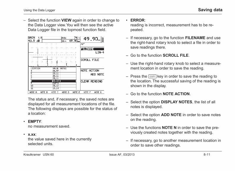
Krautkramer USN 60 Issue AF, 03/2013 8-11
Saving data
– Select the function VIEW again in order to change tothe Data Logger view. You will then see the activeData Logger file in the topmost function field.
The status and, if necessary, the saved notes aredisplayed for all measurement locations of the file.The following displays are possible for the status ofa location:
• EMPTY:no measurement saved.
• x.xx:the value saved here in the currentlyselected units.
• ERROR:reading is incorrect, measurement has to be re-peated.
– If necessary, go to the function FILENAME and usethe right-hand rotary knob to select a file in order tosave readings there.
– Go to the function SCROLL FILE.
– Use the right-hand rotary knob to select a measure-ment location in order to save the reading.
– Press the c key in order to save the reading tothe location. The successful saving of the reading isshown in the display.
– Go to the function NOTE ACTION.
– Select the option DISPLAY NOTES, the list of allnotes is displayed.
– Select the option ADD NOTE in order to save noteson the reading.
– Use the functions NOTE N in order to save the pre-viously created notes together with the reading.
– If necessary, go to another measurement location inorder to save other readings.
Using the Data Logger
8-12 Issue AF, 03/2013 Krautkramer USN 60
Saving data
A Attention:
After a reading has been saved, the USN 60 automati-cally goes to the next measurement location. Makesure that you only save the readings to vacant mea-surement locations. Otherwise readings that are al-ready saved will then be overwritten without notice.
H Note:
In order to permanently save data, you should transferthem to a PC. The software required for this can beordered from GE Inspection Technologies (please seechapter 2).
Using the Data Logger
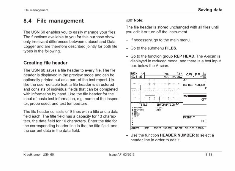
Krautkramer USN 60 Issue AF, 03/2013 8-13
Saving data
8.4 File management
The USN 60 enables you to easily manage your files.The functions available to you for this purpose showonly irrelevant differences between dataset and DataLogger and are therefore described jointly for both filetypes in the following.
Creating file headerThe USN 60 saves a file header to every file. The fileheader is displayed in the preview mode and can beoptionally printed out as a part of the test report. Un-like the user-editable text, a file header is structuredand consists of individual fields that can be completedwith information by hand. Use the file header for theinput of basic test information, e.g. name of the inspec-tor, probe used, and test temperature.
The file header consists of 9 lines with a title and a datafield each. The title field has a capacity for 13 charac-ters, the data field for 16 characters. Enter the title forthe corresponding header line in the the title field, andthe current data in the data field.
H Note:
The file header is stored unchanged with all files untilyou edit it or turn off the instrument.
– If necessary, go to the main menu.
– Go to the submenu FILES.
– Go to the function group REP HEAD. The A-scan isdisplayed in reduced mode, and there is a text inputbox below the A-scan.
– Use the function HEADER NUMBER to select aheader line in order to edit it.
File management
8-14 Issue AF, 03/2013 Krautkramer USN 60
Saving data
– Set the function EDIT to ON. The number of the se-lected header line is marked, and the cursor is lo-cated in the corresponding data field. The Editormenu is displayed in the menu bar.
– Edit the file header.
– To close the process of editing, set the functionEDIT to OFF. The file header is now created andsaved in this form with every file.
– If necessary, set the function PRINT ? to ON in or-der to record the file header in the test report.
Creating memo textsThe USN 60 saves a memo text to every file. Thememo text is displayed in the preview mode and there-fore makes the data management easier. Memo textscomprise a maximum of 80 characters that you arefree to input. If required, memo texts can also be re-corded in the test report.
H Note:
A memo text is saved unchanged with all files until youedit it or turn off the instrument.
– If necessary, go to the main menu.
– Select the submenu FILES.
– Go to the function group MEMO. The A-scan is dis-played in reduced mode, and there is a text inputbox below the A-scan.
File management
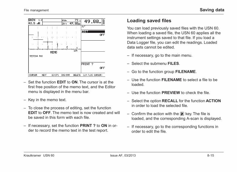
Krautkramer USN 60 Issue AF, 03/2013 8-15
Saving data
– Set the function EDIT to ON. The cursor is at thefirst free position of the memo text, and the Editormenu is displayed in the menu bar.
– Key in the memo text.
– To close the process of editing, set the functionEDIT to OFF. The memo text is now created and willbe saved in this form with each file.
– If necessary, set the function PRINT ? to ON in or-der to record the memo text in the test report.
Loading saved filesYou can load previously saved files with the USN 60.When loading a saved file, the USN 60 applies all theinstrument settings saved to that file. If you load aData Logger file, you can edit the readings. Loadeddata sets cannot be edited.
– If necessary, go to the main menu.
– Select the submenu FILES.
– Go to the function group FILENAME.
– Use the function FILENAME to select a file to beloaded.
– Use the function PREVIEW to check the file.
– Select the option RECALL for the function ACTIONin order to load the selected file.
– Confirm the action with the h key. The file isloaded, and the corresponding A-scan is displayed.
– If necessary, go to the corresponding functions inorder to edit the file.
File management
8-16 Issue AF, 03/2013 Krautkramer USN 60
Saving data
Editing saved filesFiles can be edited even after saving. You can subse-quently edit the memo texts and header data of allfiles. Moreover, if you’re using Data Logger files, youcan subsequently create notes, record new readings,and evaluate them.
– Load a saved file in order to edit it.
– Edit as required.
– Select the option SAVE EDITS for the functionACTION in order to save the edited data.
– Confirm the action with the h key. The edited file isnow saved.
Deleting saved filesYou can delete any file saved.
A Attention:
If you delete a file, the file is deleted including all thesaved readings and the additional information.
– Load the file that you want to delete.
– Use the function PREVIEW to check the file.
– Select the option CLEAR for the function ACTIONin order to delete the selected file.
– Confirm the action with the h key. The successfulfile deletion is indicated by a message in the menubar.
File management
Krautkramer USN 60 Issue AF, 03/2013 9-1
DAC/TCG option 9

9-2 Issue AF, 03/2013 Krautkramer USN 60
DAC/TCG option TCG/DAC
9.1 TCG/DAC
Because of the aperture angle of the sound beam andof the sound attenuation in the material, the echoheight of reflectors of identical size depends on thedistance from the probe.
A Distance-Amplitude Curve (DAC), recorded usingdefined reference reflectors, represents these effectsgraphically.
The TCG/DAC option in the USN 60 can compensatefor these effects.
In this connection, the gain is varied depending on thetime of flight in such a way that the echoes appear atthe same level on the screen, regardless of their dis-tance. In consequence of this, the echo amplitude onlydepends on the reflection behavior of the reflector.
If you use a reference block containing artificial reflec-tors corresponding to the natural flaws of your test ob-ject in order to record a DAC, you can use the echoamplitude of a flaw echo for evaluation without any fur-ther corrections. The reference block should be madeof the same material as the test object.
Every artificial reflector is scanned, the echo peakedand then recorded.
The TCG/DAC function brings all reference echoes to80% screen height.
The maximum dynamic range is 40 dB;the maximum curve slope is 12 dB/µs;the maximum number of curve points is 16.
The function DAC/TCG enables you to:
• record a Distance-Amplitude Curve and to store itas an integral part of the current data set.
• display the Distance-Amplitude Curve (DAC) of thereference echoes.
• activate the TCG (Time-Corrected Gain) to in-crease the gain in distance-dependent mode so thatall reference echoes reach the same screen height.The amplitude evaluation of echo indications is car-ried out in relation to the first reference echo in thiscase.
• activate the TCG as described above, however, witha simultaneous display of the TCG/DAC function.
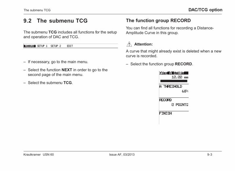
Krautkramer USN 60 Issue AF, 03/2013 9-3
DAC/TCG optionThe submenu TCG
9.2 The submenu TCG
The submenu TCG includes all functions for the setupand operation of DAC and TCG.
– If necessary, go to the main menu.
– Select the function NEXT in order to go to thesecond page of the main menu.
– Select the submenu TCG.
The function group RECORDYou can find all functions for recording a Distance-Amplitude Curve in this group.
A Attention:
A curve that might already exist is deleted when a newcurve is recorded.
– Select the function group RECORD.
9-4 Issue AF, 03/2013 Krautkramer USN 60
DAC/TCG option
H Note:
The recording of reference echoes for a DAC must al-ways be carried out by means of the A gate.
GATE A START
This function allows you to position the A gate on thereference echo.
– Select the function GATE A START.
– If necessary, use the v key to toggle betweencoarse and fine setting.
– Use the right-hand rotary knob to position the gate.
A THRESHOLD
This is where you set the threshold of the A gate.
– Select the function A THRESHOLD
– If necessary, use the v key to toggle betweencoarse and fine setting.
– Use the right-hand rotary knob to set the gatethreshold.
RECORD
This function allows you to record the echo in the Agate as reference echo.
H Note:
The highest echo in the gate is always recorded asreference echo.
– Select the function RECORD.
– Use the v key to record the reference echo. Thecounter POINTS is incremented step by step from0 ... 16 during this.
FINISH
This is where you finish the recording of a Distance-Amplitude Curve.
– Select the function FINISH. The recording of theDistance-Amplitude Curve stops immediately, andthe function group SETUP 1 appears.
The submenu TCG
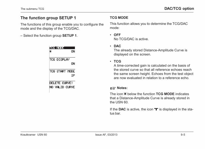
Krautkramer USN 60 Issue AF, 03/2013 9-5
DAC/TCG option
The function group SETUP 1The functions of this group enable you to configure themode and the display of the TCG/DAC.
– Select the function group SETUP 1.
TCG MODE
This function allows you to determine the TCG/DACmode:
• OFFNo TCG/DAC is active.
• DACThe already stored Distance-Amplitude Curve isdisplayed on the screen.
• TCGA time-corrected gain is calculated on the basis ofthe stored curve so that all reference echoes reachthe same screen height. Echoes from the test objectare now evaluated in relation to a reference echo.
H Notes:
The icon below the function TCG MODE indicatesthat a Distance-Amplitude Curve is already stored inthe USN 60.
If the DAC is active, the icon is displayed in the sta-tus bar.
The submenu TCG

9-6 Issue AF, 03/2013 Krautkramer USN 60
DAC/TCG option
– Select the function TCG MODE.
– Use the right-hand rotary knob to select therequired mode.
TCG DISPLAY
This function serves for the display of the Distance-Amplitude Curve. The gain rise is graphically dis-played.
– Select the function TCG DISPLAY.
– Use the right-hand rotary knob to choose therequired option.
TCG START MODE
Choose whether you want to display the TCG/DACfrom the initial pulse (IP) or from the surface of the testpiece (IF).
– Select the function TCG START MODE.
– Use the right-hand rotary knob to choose therequired option.
DELETE CURVE !
This function enables you to delete an already existingDistance-Amplitude Curve.
A Attention:
Without a Distance-Amplitude Curve, the USN 60 cancalculate no TCG.
– Select the function DELETE CURVE !
– Press the corresponding v key in order to deletethe curve.
– Confirm the deletion of curve by means of theh key.
The submenu TCG
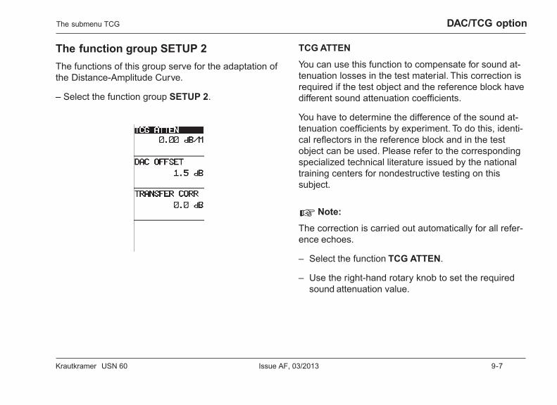
Krautkramer USN 60 Issue AF, 03/2013 9-7
DAC/TCG option
The function group SETUP 2The functions of this group serve for the adaptation ofthe Distance-Amplitude Curve.
– Select the function group SETUP 2.
TCG ATTEN
You can use this function to compensate for sound at-tenuation losses in the test material. This correction isrequired if the test object and the reference block havedifferent sound attenuation coefficients.
You have to determine the difference of the sound at-tenuation coefficients by experiment. To do this, identi-cal reflectors in the reference block and in the testobject can be used. Please refer to the correspondingspecialized technical literature issued by the nationaltraining centers for nondestructive testing on thissubject.
H Note:
The correction is carried out automatically for all refer-ence echoes.
– Select the function TCG ATTEN.
– Use the right-hand rotary knob to set the requiredsound attenuation value.
The submenu TCG
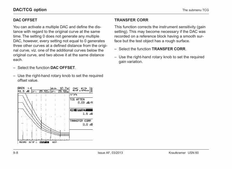
9-8 Issue AF, 03/2013 Krautkramer USN 60
DAC/TCG option
DAC OFFSET
You can activate a multiple DAC and define the dis-tance with regard to the original curve at the sametime. The setting 0 does not generate any multipleDAC, however, every setting not equal to 0 generatesthree other curves at a defined distance from the origi-nal curve, viz. one of the additional curves below theoriginal curve, and two above it at the same distanceeach.
– Select the function DAC OFFSET.
– Use the right-hand rotary knob to set the requiredoffset value.
TRANSFER CORR
This function corrects the instrument sensitivity (gainsetting). This may become necessary if the DAC wasrecorded on a reference block having a smooth sur-face but the test object has a rough surface.
– Select the function TRANSFER CORR.
– Use the right-hand rotary knob to set the requiredgain variation.
The submenu TCG
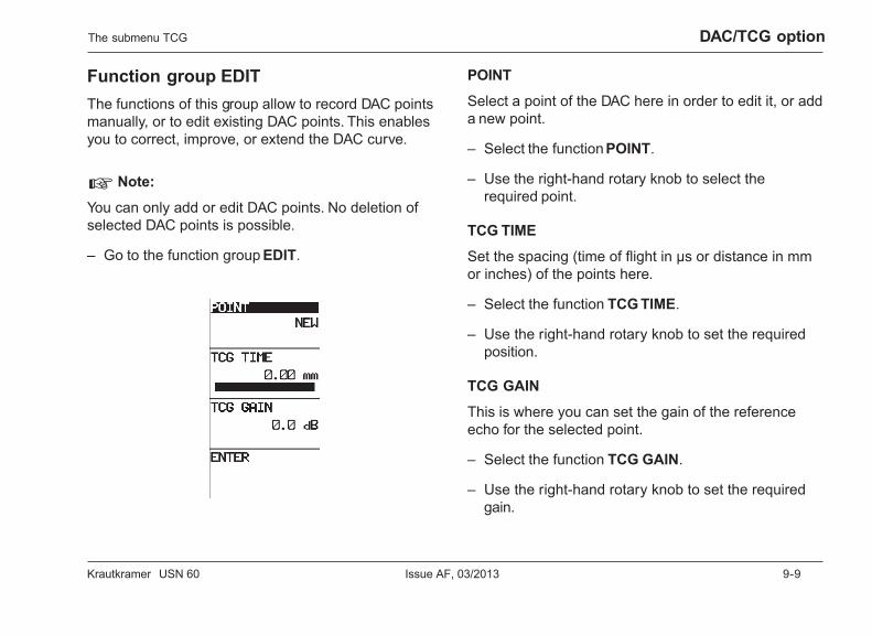
Krautkramer USN 60 Issue AF, 03/2013 9-9
DAC/TCG option
Function group EDITThe functions of this group allow to record DAC pointsmanually, or to edit existing DAC points. This enablesyou to correct, improve, or extend the DAC curve.
H Note:
You can only add or edit DAC points. No deletion ofselected DAC points is possible.
– Go to the function group EDIT.
POINT
Select a point of the DAC here in order to edit it, or adda new point.
– Select the function POINT.
– Use the right-hand rotary knob to select therequired point.
TCG TIME
Set the spacing (time of flight in µs or distance in mmor inches) of the points here.
– Select the function TCG TIME.
– Use the right-hand rotary knob to set the requiredposition.
TCG GAIN
This is where you can set the gain of the referenceecho for the selected point.
– Select the function TCG GAIN.
– Use the right-hand rotary knob to set the requiredgain.
The submenu TCG
9-10 Issue AF, 03/2013 Krautkramer USN 60
DAC/TCG option
ENTER
This function enables you to record the changes in theDistance-Amplitude Curve.
– Select the function ENTER.
– Use the corresponding v key to save the changes.
9.3 Recording a Distance-Amplitude Curve
The Distance-Amplitude Curve represents the dis-tance law of a specified, artificial reflector in thepresent reference block. It is practically determined bymeans of a reference block containing artificial reflec-tors at varying depths. In this connection, the echoamplitudes of the reflectors form the evaluation thresh-old for the natural reflector echoes from the test object.If the echoes of reflectors exceed this threshold, theyare considered as recordable.
In order to use the TCG/DAC function of the USN 60,you have to first record a Distance-Amplitude Curve.To do this, use a reference block made of the samematerial as the test object. The artificial flaws shouldshow the same reflection behavior as the expectedflaws.
The submenu TCG
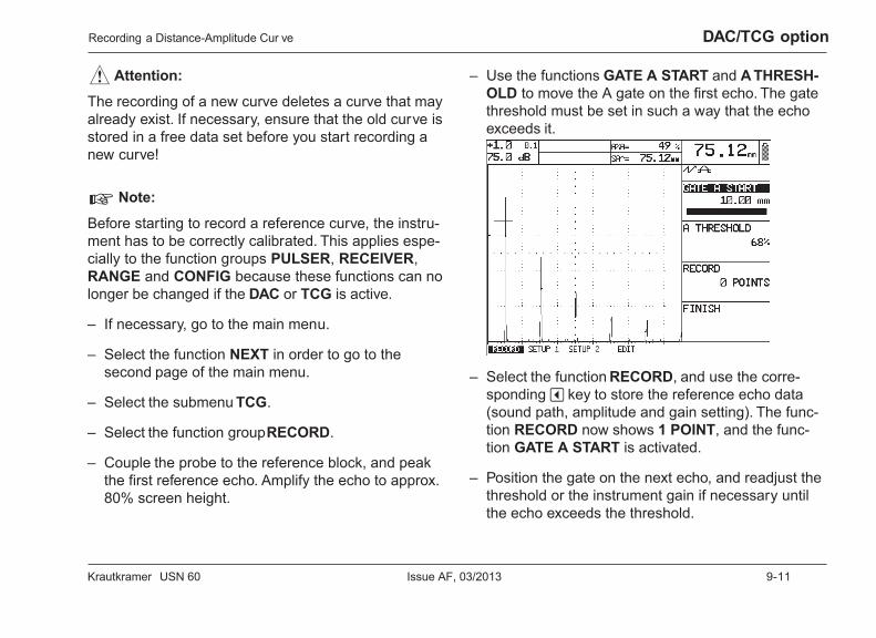
Krautkramer USN 60 Issue AF, 03/2013 9-11
DAC/TCG option
A Attention:
The recording of a new curve deletes a curve that mayalready exist. If necessary, ensure that the old curve isstored in a free data set before you start recording anew curve!
H Note:
Before starting to record a reference curve, the instru-ment has to be correctly calibrated. This applies espe-cially to the function groups PULSER, RECEIVER,RANGE and CONFIG because these functions can nolonger be changed if the DAC or TCG is active.
– If necessary, go to the main menu.
– Select the function NEXT in order to go to thesecond page of the main menu.
– Select the submenu TCG.
– Select the function group RECORD.
– Couple the probe to the reference block, and peakthe first reference echo. Amplify the echo to approx.80% screen height.
– Use the functions GATE A START and A THRESH-OLD to move the A gate on the first echo. The gatethreshold must be set in such a way that the echoexceeds it.
– Select the function RECORD, and use the corre-sponding v key to store the reference echo data(sound path, amplitude and gain setting). The func-tion RECORD now shows 1 POINT, and the func-tion GATE A START is activated.
– Position the gate on the next echo, and readjust thethreshold or the instrument gain if necessary untilthe echo exceeds the threshold.
Recording a Distance-Amplitude Cur ve
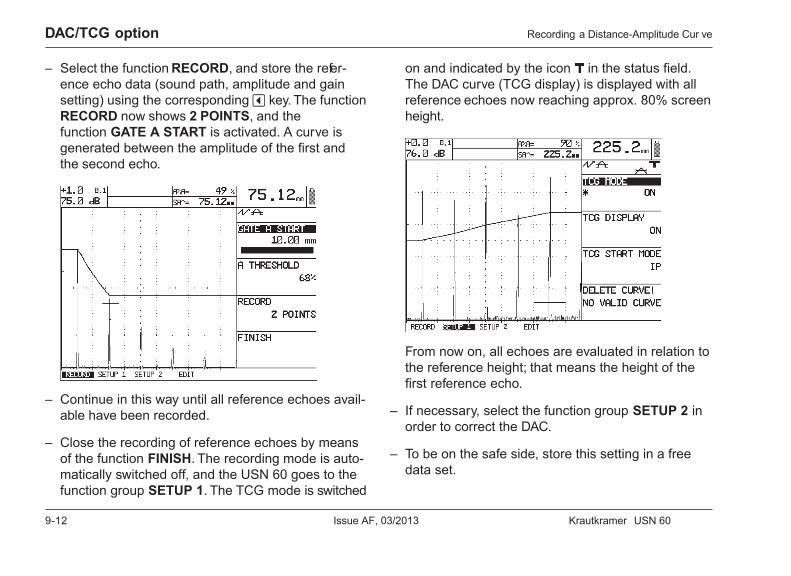
9-12 Issue AF, 03/2013 Krautkramer USN 60
DAC/TCG option
– Select the function RECORD, and store the refer-ence echo data (sound path, amplitude and gainsetting) using the corresponding v key. The functionRECORD now shows 2 POINTS, and thefunction GATE A START is activated. A curve isgenerated between the amplitude of the first andthe second echo.
– Continue in this way until all reference echoes avail-able have been recorded.
– Close the recording of reference echoes by meansof the function FINISH. The recording mode is auto-matically switched off, and the USN 60 goes to thefunction group SETUP 1. The TCG mode is switched
on and indicated by the icon in the status field.The DAC curve (TCG display) is displayed with allreference echoes now reaching approx. 80% screenheight.
From now on, all echoes are evaluated in relation tothe reference height; that means the height of thefirst reference echo.
– If necessary, select the function group SETUP 2 inorder to correct the DAC.
– To be on the safe side, store this setting in a freedata set.
Recording a Distance-Amplitude Cur ve

Krautkramer USN 60 Issue AF, 03/2013 9-13
DAC/TCG option
9.4 Creating a theoreticalDistance-Amplitude Curve
If it’s not possible for you to record a Distance-Ampli-tude Curve by means of a reference block containingknown flaws, the USN 60 enables you to alternativelycreate a theoretical Distance-Amplitude Curve. Youcan derive the data regarding spacing and gain of sev-eral points of a Distance-Amplitude Curve from thecorresponding DGS diagram.
You can subsequently enter the derived data in theUSN 60 using the function group RECORD in order togenerate a Distance-Amplitude Curve.
H Note:
You can only add or edit DAC points. No deletion ofselected DAC points is possible.
– If necessary, go to the main menu.
– Select the function NEXT in order to go to the sec-ond page of the main menu.
– Select the submenu TCG.
– Select the function group EDIT.
– Choose the option NEW for the function POINT.
– Use the function TCG TIME to set the spacing ofthe new DAC point.
– Use the function TCG GAIN to set the gain of thenew DAC point.
– Go to the function ENTER, and confirm the data ofthe new DAC point using the corresponding v key.
– Add other DAC points as described above.
Creating a theoretical Distance-Amplitude Cur ve
9-14 Issue AF, 03/2013 Krautkramer USN 60
DAC/TCG option
9.5 Echo evaluation with TCG/DAC
To be able to evaluate a flaw indication by means ofthe TCG/DAC function, certain requirements have tobe met:
• The Distance-Amplitude Curve must already berecorded.
• It only applies to the same probe that was used forrecording the curve. Even another probe of thesame type must not be used!
• The curve and the TCG only apply to the materialcorresponding to the material of the reference block.
• All functions affecting the echo amplitude must beset in the same way as they were when the curvewas recorded. This applies in particular to the fol-lowing function groups: PULSER, RECEIVER,RANGE and CONFIG.
• DETECTION is set to PEAK.
• AMPLITUDE is set to dB THRESHOLD.
– Select the echo amplitude (as dB difference with re-gard to the curve) for the display in the largedisplay box.
Echo evaluation with TCG/DAC

Krautkramer USN 60 Issue AF, 03/2013 9-15
DAC/TCG option
DAC mode– Peak the echo of a probable flaw, and move the gate
so that the echo data are evaluated.
– Determine the sound path in the display boxes forreadings and, in addition, the (reduced) projectiondistance as well as the flaw depth if you are usingangle-beam probes. Whether or not the echo isrecordable, can be immediately seen from theA-scan.
You can also easily determine the dB amount by whichthe response threshold is exceeded:
– Adjust the gate threshold exactly to the intersectionpoint of the curve with the probable flaw indication.The value dBtA in the corresponding display boxindicates the amount of dB by which the flaw echoexceeds the curve, i.e. to what extent the echo indi-cation exceeds the reference echo.
Echo evaluation with TCG/DAC
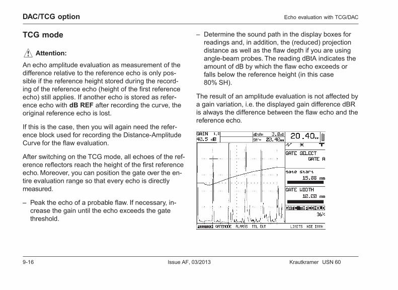
9-16 Issue AF, 03/2013 Krautkramer USN 60
DAC/TCG option
TCG mode
A Attention:
An echo amplitude evaluation as measurement of thedifference relative to the reference echo is only pos-sible if the reference height stored during the record-ing of the reference echo (height of the first referenceecho) still applies. If another echo is stored as refer-ence echo with dB REF after recording the curve, theoriginal reference echo is lost.
If this is the case, then you will again need the refer-ence block used for recording the Distance-AmplitudeCurve for the flaw evaluation.
After switching on the TCG mode, all echoes of the ref-erence reflectors reach the height of the first referenceecho. Moreover, you can position the gate over the en-tire evaluation range so that every echo is directlymeasured.
– Peak the echo of a probable flaw. If necessary, in-crease the gain until the echo exceeds the gatethreshold.
Echo evaluation with TCG/DAC
– Determine the sound path in the display boxes forreadings and, in addition, the (reduced) projectiondistance as well as the flaw depth if you are usingangle-beam probes. The reading dBtA indicates theamount of dB by which the flaw echo exceeds orfalls below the reference height (in this case80% SH).
The result of an amplitude evaluation is not affected bya gain variation, i.e. the displayed gain difference dBRis always the difference between the flaw echo and thereference echo.
Krautkramer USN 60 Issue AF, 03/2013 10-1
DGS option 10
10-2 Issue AF, 03/2013 Krautkramer USN 60
DGS option
10.1 The DGS method
The DGS (Distance – Gain – Size) function enablesyou to compare the reflectivity of a natural flaw in thetest object with the reflectivity of a theoretical flaw(circular disk reflector) at the same depth.
A Attention:
You are comparing the reflectivity of a natural flaw withthat of a theoretical flaw. No definite conclusions withregard to the natural flaw (roughness, inclination, etc.)are allowed.
This comparison of the reflectivity is based on the so-called DGS diagram. This diagram consists of a set ofcurves showing the interrelationship of three influencingfactors:
• distance D between the probe and the circular diskreflector/flaw
• relative gain G for backwall echoes and echoes fromcircular disks having different diameters
• size S of the circular disk reflector (diameter). Theinfluencing factor S remains constant for each curveof the set of curves.
The DGS method
The advantage of the DGS method lies in the fact thatyou can have reproducible evaluations of small dis-continuities. The reproducibility is most of all importantwhenever you want to carry out for example an accep-tance test.
Besides the influencing factors already mentionedabove, there are other factors that determine the curveshape:
• Sound attenuation
• Transfer losses
• Amplitude correction value
• Probe
The following parameters of the probe have an effect onthe curve shape:
• Element diameter
• Transducer frequency
• Delay line length
• Sound velocity in the delay line

Krautkramer USN 60 Issue AF, 03/2013 10-3
DGS optionThe DGS method
You can adapt these parameters in the USN 60 so thatyou are able to use the DGS method with many differ-ent probes and on various materials.
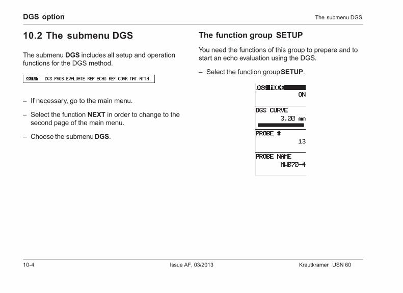
10-4 Issue AF, 03/2013 Krautkramer USN 60
DGS option
10.2 The submenu DGS
The submenu DGS includes all setup and operationfunctions for the DGS method.
– If necessary, go to the main menu.
– Select the function NEXT in order to change to thesecond page of the main menu.
– Choose the submenu DGS.
The function group SETUP
You need the functions of this group to prepare and tostart an echo evaluation using the DGS.
– Select the function group SETUP.
The submenu DGS
Krautkramer USN 60 Issue AF, 03/2013 10-5
DGS option
DGS MODE
Use this function to switch the DGS mode on or off.
– Select the function DGS MODE.
– Use the right-hand rotary knob to switch the DGSmode on or off.
DGS CURVE
This is where you set the circular disk diameter to beused for displaying the DGS curve. It is also used asrecording threshold for the echo evaluations.
H Note:
You can always change the circular disk diameter forthe DGS curve.
– Select the function DGS CURVE.
– Use the right-hand rotary knob to set the requiredcircular disk diameter.
PROBE #
Use this function to choose the probe used. There are24 probes with their corresponding parameters stored inthe instrument. The instrument takes the probe par-ameters into account when generating the DGS dia-gram.
You will find an overview of the stored probes and theircorresponding parameters on the next page.
H Note:
You will find a user-programmable probe at the probenumber 1. Use this probe number if the probe thatyou’re using is not stored in the instrument.
– Select the function PROBE #.
– Use the right-hand rotary knob to choose the requiredprobe.
The submenu DGS
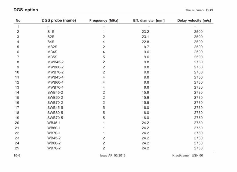
10-6 Issue AF, 03/2013 Krautkramer USN 60
DGS option
No. DGS probe (name) Frequency [MHz] Eff. diameter [mm] Delay velocity [m/s]1 – – – –2 B1S 1 23.2 25003 B2S 2 23.1 25004 B4S 4 22.8 25005 MB2S 2 9.7 25006 MB4S 4 9.6 25007 MB5S 5 9.6 25008 MWB45-2 2 9.8 27309 MWB60-2 2 9.8 2730
10 MWB70-2 2 9.8 273011 MWB45-4 4 9.8 273012 MWB60-4 4 9.8 273013 MWB70-4 4 9.8 273014 SWB45-2 2 15.9 273015 SWB60-2 2 15.9 273016 SWB70-2 2 15.9 273017 SWB45-5 5 16.0 273018 SWB60-5 5 16.0 273019 SWB70-5 5 16.0 273020 WB45-1 1 24.2 273021 WB60-1 1 24.2 273022 WB70-1 1 24.2 273023 WB45-2 2 24.2 273024 WB60-2 2 24.2 273025 WB70-2 2 24.2 2730
The submenu DGS
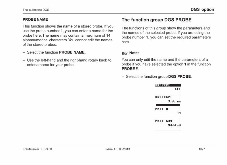
Krautkramer USN 60 Issue AF, 03/2013 10-7
DGS option
PROBE NAME
This function shows the name of a stored probe. If youuse the probe number 1, you can enter a name for theprobe here. The name may contain a maximum of 14alphanumerical characters. You cannot edit the namesof the stored probes.
– Select the function PROBE NAME.
– Use the left-hand and the right-hand rotary knob toenter a name for your probe.
The function group DGS PROBE
The functions of this group show the parameters andthe names of the selected probe. If you are using theprobe number 1, you can set the required parametershere.
H Note:
You can only edit the name and the parameters of aprobe if you have selected the option 1 in the functionPROBE #.
– Select the function group DGS PROBE.
The submenu DGS
10-8 Issue AF, 03/2013 Krautkramer USN 60
DGS option
XTAL FREQUENCY
This is where you can set the frequency of the trans-ducer element.
– Select the function XTAL FREQUENCY.
– Use the right-hand rotary knob to set the requiredfrequency.
EFF. DIAMETER
This is where you can set the effective element dia-meter of the probe.
– Select the function EFF. DIAMETER.
– Use the right-hand rotary knob to set the requiredvalue.
DELAY VELOCITY
This is where you can set the sound velocity in theprobe’s delay line.
– Select the function DELAY VELOCITY.
– Use the right-hand rotary knob to set the requiredvalue.
PROBE NAME
This is where you can enter a name for the probe used.The name may contain a maximum of 14 alpha-numerical characters.
– Select the function PROBE NAME.
– Use the left-hand and the right-hand rotary knob toenter a name for your probe.
The submenu DGS

Krautkramer USN 60 Issue AF, 03/2013 10-9
DGS option
The function group EVALUATE
The functions of this group are used for flaw evaluationby means of the DGS curve.
– Select the function group EVALUATE.
EVAL. RESULT
USN 60 has two options available to you for the flawevaluation by means of the DGS curve. The evaluationresult can be displayed either as dB to curve or as theequivalent reflector size. The following settings arepossible:
• DB TO CURVEindicates the difference between the echo height andthe DGS curve in dB (only if the option dB THRES-HOLD has been chosen for the function AMPLI-TUDE)
• ERSindicates the equivalent reflector size of a flaw echo,i.e. calculated on the basis of the echo amplitude
– Select the function EVAL. RESULT.
– Use the right-hand rotray knob to choose the requireddisplay option.
The submenu DGS

10-10 Issue AF, 03/2013 Krautkramer USN 60
DGS option
DGS CURVE
This is where you can set the circular disk diameter tobe used for displaying the DGS curve. It is also usedas recording threshold for the echo evaluations.
H Note:
You can always change the circular disk diameter forthe DGS curve.
– Select the function DGS CURVE.
– Use the right-hand rotary knob to set the requiredcircular disk diameter.
The function group REF ECHO
The functions of this group are used for recording thereference echo.
– Select the function group REF ECHO.
The submenu DGS
Krautkramer USN 60 Issue AF, 03/2013 10-11
DGS option
GATE A START
The recording of a reference echo is always carried outin the A gate. This is where you set the gate start forthe A gate.
– Select the function GATE A START.
– Use the right-hand rotary knob to set the gate start.
REFERENCE TYPE
This is where you choose the type of the referencereflector used. You can use a backwall, a circular diskor, with limitations, even a side-drilled hole as a refer-ence reflector. It must have a diameter corresponding toat least 1.5 times the wavelength used, and the dis-tance must be 1.5 times the near field length.
The table on the next page shows these minimum datafor the existing probes in steel. It shows the conditionsfor using side-drilled holes as reference reflectors insteel. The values must be converted accordingly forother materials.
The following settings are possible:
• BW
• SDH
• FBH (circular disk)
– Select the function REFERENCE TYPE.
– Use the right-hand rotary knob to choose the refer-ence reflector.
The submenu DGS
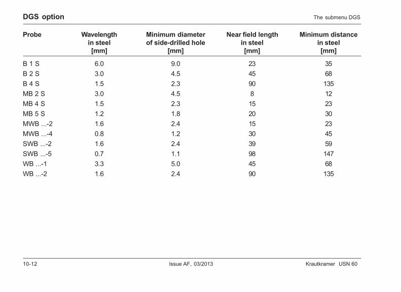
10-12 Issue AF, 03/2013 Krautkramer USN 60
DGS option
Probe Wavelength Minimum diameter Near field length Minimum distancein steel of side-drilled hole in steel in steel[mm] [mm] [mm] [mm]
B 1 S 6.0 9.0 23 35B 2 S 3.0 4.5 45 68B 4 S 1.5 2.3 90 135MB 2 S 3.0 4.5 8 12MB 4 S 1.5 2.3 15 23MB 5 S 1.2 1.8 20 30MWB ...-2 1.6 2.4 15 23MWB ...-4 0.8 1.2 30 45SWB ...-2 1.6 2.4 39 59SWB ...-5 0.7 1.1 98 147WB ...-1 3.3 5.0 45 68WB ...-2 1.6 2.4 90 135
The submenu DGS
Krautkramer USN 60 Issue AF, 03/2013 10-13
DGS option
REF SIZE
This is where you set the diameter of the referencereflector. The setting depends on the reflector typeused. The only possible setting for a backwall isINFINITY. If you are using a circular disk or a side-drilled hole, you have to set a numerical value.
– Select the function REF SIZE.
– Use the right-hand rotary knob to set the diameter.
RECORD REF
You can use this function to record the reference echo.
A Attention:
A reference echo that has already been recorded isdeleted if a new reference echo is recorded.
– Select the function RECORD REF.
– Press the corresponding key v in order to record thereference echo. If a reference echo already exists, awarning message is displayed.
– Use the key h to confirm the message and torecord the reference echo.
The successful recording of a reference echo is indi-cated by an icon in the status field.
The submenu DGS
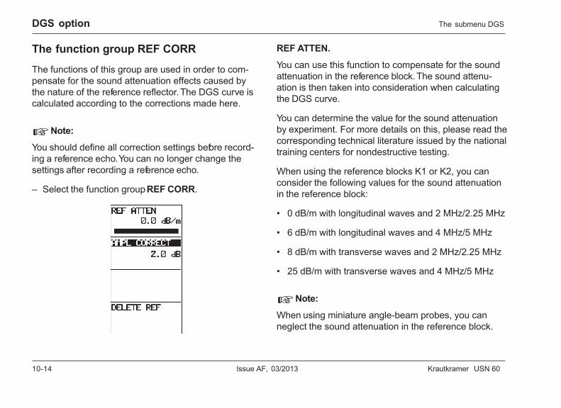
10-14 Issue AF, 03/2013 Krautkramer USN 60
DGS option
The function group REF CORR
The functions of this group are used in order to com-pensate for the sound attenuation effects caused bythe nature of the reference reflector. The DGS curve iscalculated according to the corrections made here.
H Note:
You should define all correction settings before record-ing a reference echo. You can no longer change thesettings after recording a reference echo.
– Select the function group REF CORR.
REF ATTEN.
You can use this function to compensate for the soundattenuation in the reference block. The sound attenu-ation is then taken into consideration when calculatingthe DGS curve.
You can determine the value for the sound attenuationby experiment. For more details on this, please read thecorresponding technical literature issued by the nationaltraining centers for nondestructive testing.
When using the reference blocks K1 or K2, you canconsider the following values for the sound attenuationin the reference block:
• 0 dB/m with longitudinal waves and 2 MHz/2.25 MHz
• 6 dB/m with longitudinal waves and 4 MHz/5 MHz
• 8 dB/m with transverse waves and 2 MHz/2.25 MHz
• 25 dB/m with transverse waves and 4 MHz/5 MHz
H Note:
When using miniature angle-beam probes, you canneglect the sound attenuation in the reference block.
The submenu DGS
Krautkramer USN 60 Issue AF, 03/2013 10-15
DGS option
– Select the function REF ATTEN.
– Use the right-hand rotary knob to set the requiredvalue.
AMPL CORRECT
This function is used for the amplitude correction. Youneed the amplitude correction if you are using an angle-beam probe and the quadrant echo from the referenceblocks K1 or K2 as a reference reflector.
The values for the amplitude correction were deter-mined by experiment for every angle-beam probe. Youwill find the values in your probe’s data sheet under theheading ∆VK1 or ∆VK2, depending on the reference blockused.
– Select the function AMPL CORRECT.
– Use the right-hand rotary knob to set the indicatedvalue.
DELETE REF
You can use this function to delete the current refer-ence echo.
– Select the function DELETE REF.
– Use the right-hand rotary knob to activate the func-tion and to delete the reference echo.
– Use the key h to confirm the deletion.
The submenu DGS
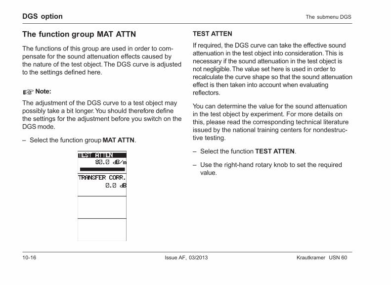
10-16 Issue AF, 03/2013 Krautkramer USN 60
DGS option
The function group MAT ATTN
The functions of this group are used in order to com-pensate for the sound attenuation effects caused bythe nature of the test object. The DGS curve is adjustedto the settings defined here.
H Note:
The adjustment of the DGS curve to a test object maypossibly take a bit longer. You should therefore definethe settings for the adjustment before you switch on theDGS mode.
– Select the function group MAT ATTN.
TEST ATTEN
If required, the DGS curve can take the effective soundattenuation in the test object into consideration. This isnecessary if the sound attenuation in the test object isnot negligible. The value set here is used in order torecalculate the curve shape so that the sound attenuationeffect is then taken into account when evaluatingreflectors.
You can determine the value for the sound attenuationin the test object by experiment. For more details onthis, please read the corresponding technical literatureissued by the national training centers for nondestruc-tive testing.
– Select the function TEST ATTEN.
– Use the right-hand rotary knob to set the requiredvalue.
The submenu DGS
Krautkramer USN 60 Issue AF, 03/2013 10-17
DGS option
TRANSFER CORR.
This function is used for the transfer correction. Thetest sensitivity is varied by this value without recalcu-lating the curve. This correction is necessary if the testobject has another surface quality than the referenceblock.
You can determine the value for the transfer correctionby experiment. For more details on this, please read thecorresponding technical literature of the national trainingcenters for nondestructive testing.
– Select the function TRANSFER CORR.
– Use the right-hand rotary knob to set the requiredvalue.
10.3 Using the DGS
H Note:
In order to use the DGS option, the instrument mustalready be calibrated because all functions affecting theDGS evaluation can no longer be changed after record-ing the reference echo. This applies in particular to thefunctions in the submenus PLSRCVR and TRIG.Please refer to the section 7.3 Calibrating the USN 60.
Choosing the probe
The probe used is an important influencing factor forthe shape of the DGS curve. You must therefore choosethe probe before carrying out a flaw evaluation bymeans of the DGS method. There are 24 probes withtheir corresponding parameters stored in the instrument.If you have chosen a probe, the instrument automati-cally displays the corresponding probe name and theparameters of the probe. The instrument takes theprobe’s parameters into account when calculating theDGS curve.
Using the DGS
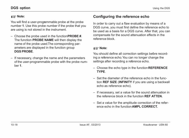
10-18 Issue AF, 03/2013 Krautkramer USN 60
DGS option
H Note:
You will find a user-programmable probe at the probenumber 1. Use this probe number if the probe that youare using is not stored in the instrument.
– Choose the probe used in the function PROBE #.The function PROBE NAME will then display thename of the probe used. The corresponding par-ameters are displayed in the function groupDGS PROBE.
– If necessary, change the name and the parametersof the user-programmable probe with the probe num-ber 1.
Configuring the reference echo
In order to carry out a flaw evaluation by means of aDGS curve, you must first define the reference echo tobe used as a basis for a DGS curve. After that, you cancompensate for the sound attenuation effects in thereference block.
H Note:
You should define all correction settings before record-ing a reference echo. You can no longer change thesettings after recording a reference echo.
– Choose the echo type in the function REFERENCETYPE.
– Set the diameter of the reference echo in the func-tion REF SIZE (INFINITY if you are using a backwallecho as reference echo).
– If necessary, set a value for the sound attenuation inthe reference block in the function REF ATTEN.
– Set a value for the amplitude correction of the refer-ence echo in the function AMPL CORRECT.
Using the DGS
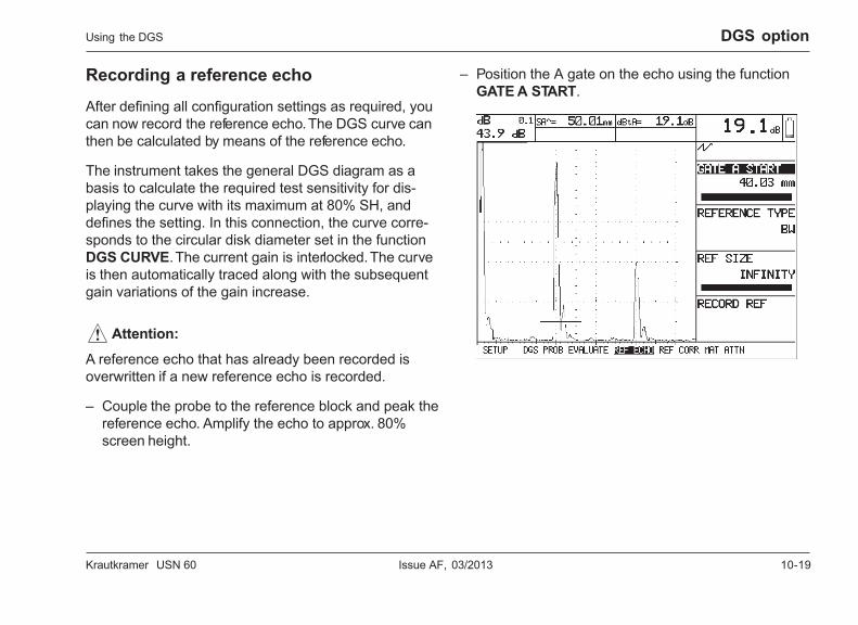
Krautkramer USN 60 Issue AF, 03/2013 10-19
DGS option
Recording a reference echo
After defining all configuration settings as required, youcan now record the reference echo. The DGS curve canthen be calculated by means of the reference echo.
The instrument takes the general DGS diagram as abasis to calculate the required test sensitivity for dis-playing the curve with its maximum at 80% SH, anddefines the setting. In this connection, the curve corre-sponds to the circular disk diameter set in the functionDGS CURVE. The current gain is interlocked. The curveis then automatically traced along with the subsequentgain variations of the gain increase.
A Attention:
A reference echo that has already been recorded isoverwritten if a new reference echo is recorded.
– Couple the probe to the reference block and peak thereference echo. Amplify the echo to approx. 80%screen height.
– Position the A gate on the echo using the functionGATE A START.
Using the DGS
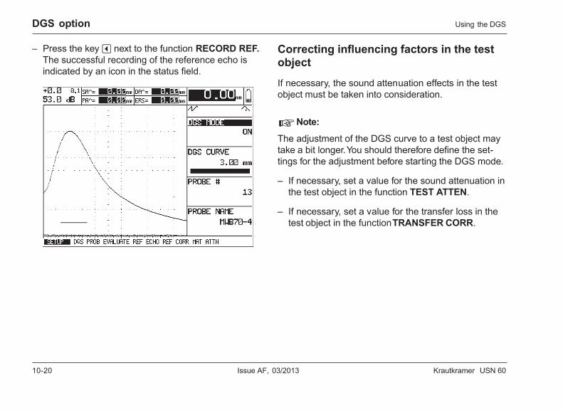
10-20 Issue AF, 03/2013 Krautkramer USN 60
DGS option
– Press the key v next to the function RECORD REF.The successful recording of the reference echo isindicated by an icon in the status field.
Correcting influencing factors in the testobject
If necessary, the sound attenuation effects in the testobject must be taken into consideration.
H Note:
The adjustment of the DGS curve to a test object maytake a bit longer. You should therefore define the set-tings for the adjustment before starting the DGS mode.
– If necessary, set a value for the sound attenuation inthe test object in the function TEST ATTEN.
– If necessary, set a value for the transfer loss in thetest object in the function TRANSFER CORR.
Using the DGS
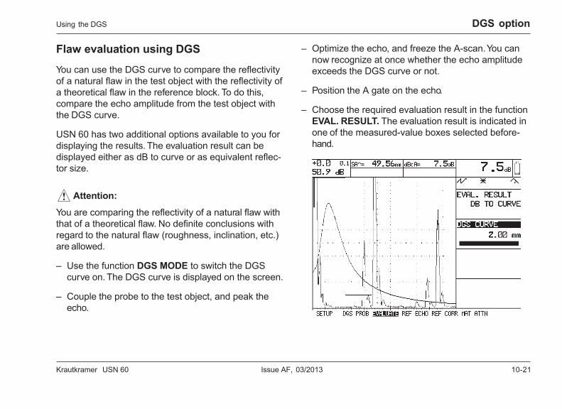
Krautkramer USN 60 Issue AF, 03/2013 10-21
DGS option
Flaw evaluation using DGS
You can use the DGS curve to compare the reflectivityof a natural flaw in the test object with the reflectivity ofa theoretical flaw in the reference block. To do this,compare the echo amplitude from the test object withthe DGS curve.
USN 60 has two additional options available to you fordisplaying the results. The evaluation result can bedisplayed either as dB to curve or as equivalent reflec-tor size.
A Attention:
You are comparing the reflectivity of a natural flaw withthat of a theoretical flaw. No definite conclusions withregard to the natural flaw (roughness, inclination, etc.)are allowed.
– Use the function DGS MODE to switch the DGScurve on. The DGS curve is displayed on the screen.
– Couple the probe to the test object, and peak theecho.
– Optimize the echo, and freeze the A-scan. You cannow recognize at once whether the echo amplitudeexceeds the DGS curve or not.
– Position the A gate on the echo.
– Choose the required evaluation result in the functionEVAL. RESULT. The evaluation result is indicated inone of the measured-value boxes selected before-hand.
Using the DGS
10-22 Issue AF, 03/2013 Krautkramer USN 60
Krautkramer USN 60 Issue AF, 03/2013 11-1
Interface echo gate option 11
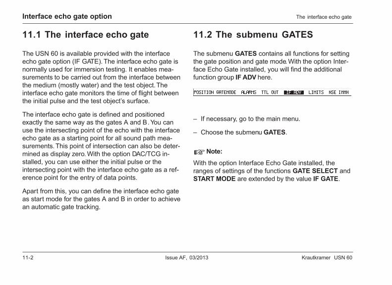
11-2 Issue AF, 03/2013 Krautkramer USN 60
Interface echo gate option The interface echo gate
11.1 The interface echo gate
The USN 60 is available provided with the interfaceecho gate option (IF GATE). The interface echo gate isnormally used for immersion testing. It enables mea-surements to be carried out from the interface betweenthe medium (mostly water) and the test object. Theinterface echo gate monitors the time of flight betweenthe initial pulse and the test object’s surface.
The interface echo gate is defined and positionedexactly the same way as the gates A and B. You canuse the intersecting point of the echo with the interfaceecho gate as a starting point for all sound path mea-surements. This point of intersection can also be deter-mined as display zero. With the option DAC/TCG in-stalled, you can use either the initial pulse or theintersecting point with the interface echo gate as a ref-erence point for the entry of data points.
Apart from this, you can define the interface echo gateas start mode for the gates A and B in order to achievean automatic gate tracking.
11.2 The submenu GATES
The submenu GATES contains all functions for settingthe gate position and gate mode. With the option Inter-face Echo Gate installed, you will find the additionalfunction group IF ADV here.
– If necessary, go to the main menu.
– Choose the submenu GATES.
H Note:
With the option Interface Echo Gate installed, theranges of settings of the functions GATE SELECT andSTART MODE are extended by the value IF GATE.
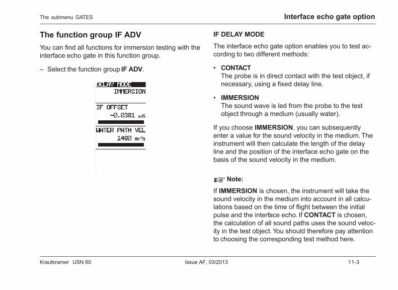
Krautkramer USN 60 Issue AF, 03/2013 11-3
Interface echo gate optionThe submenu GATES
The function group IF ADVYou can find all functions for immersion testing with theinterface echo gate in this function group.
– Select the function group IF ADV.
IF DELAY MODE
The interface echo gate option enables you to test ac-cording to two different methods:
• CONTACTThe probe is in direct contact with the test object, ifnecessary, using a fixed delay line.
• IMMERSIONThe sound wave is led from the probe to the testobject through a medium (usually water).
If you choose IMMERSION, you can subsequentlyenter a value for the sound velocity in the medium. Theinstrument will then calculate the length of the delayline and the position of the interface echo gate on thebasis of the sound velocity in the medium.
H Note:
If IMMERSION is chosen, the instrument will take thesound velocity in the medium into account in all calcu-lations based on the time of flight between the initialpulse and the interface echo. If CONTACT is chosen,the calculation of all sound paths uses the sound veloc-ity in the test object. You should therefore pay attentionto choosing the corresponding test method here.
11-4 Issue AF, 03/2013 Krautkramer USN 60
Interface echo gate option
– Select the function IF DELAY MODE.
– Use the right-hand rotary knob to set the requiredmethod.
IF OFFSET
This function is used for the exact calibration for thedistance measurements between the interface echoand the echo in the A gate. Every non-zero value variesthe sound path to the point of measurement in the inter-face echo gate.
You can determine the correction value by experimentusing a calibration standard having a known thickness.Please also refer to section 7.3 Calibrating the USN 60.
H Note:
The correction value affects all sound path measure-ments based on the interface echo. You should there-fore only use this function if you are familiar with theeffects of the variation on the measured values.
– Select the function IF OFFSET.
– Use the right-hand rotary knob to set the requiredcorrection value.
DELAY VELOCITY
This is where you can enter the sound velocity in thedelay line. The sound velocity depends on the mediumused. The sound velocity in water (1480 m/s) is factory-preset in this case.
H Note:
You can only vary the sound velocity if the optionIMMERSION is chosen for the function IF DELAYMODE. Otherwise the function is disabled.
– Select the function DELAY VELOCITY.
– Use the right-hand rotary knob to set the soundvelocity.
The submenu GATES
Krautkramer USN 60 Issue AF, 03/2013 11-5
Interface echo gate option
11.3 Using the interface echo gate
The interface echo gate option makes an additionalgate available to you for the echo monitoring. You canset up and use this gate exactly the same way as thegates A and B. You can define the interface echo gateas start mode for the gates A and B and in this wayachieve an automatic gate tracking. Apart from that,you can define the intersecting point of the echo withthe interface echo gate as display zero for the A-scan.
Setting up the interface echo gateThe interface echo gate is set up and positioned ex-actly the same way as the gates A and B. The functionSTART MODE is an exception from this. You can onlyuse the initial pulse as start mode of the interface echogate.
You will find all functions for setting up the gates in thesubmenu GATES. They are described in chapter 5.4.
– Go to the submenu GATES.
– Set up the interface echo gate as required.
Using the interface echo gate
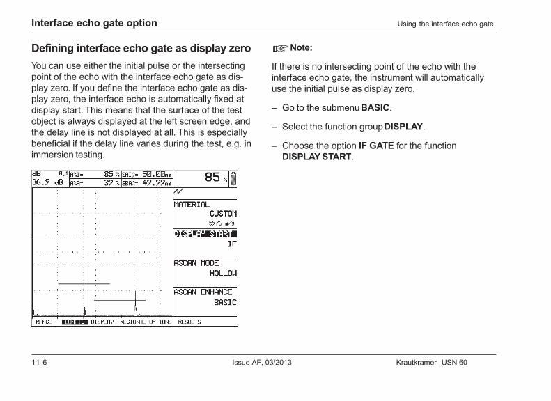
11-6 Issue AF, 03/2013 Krautkramer USN 60
Interface echo gate option
Defining interface echo gate as display zeroYou can use either the initial pulse or the intersectingpoint of the echo with the interface echo gate as dis-play zero. If you define the interface echo gate as dis-play zero, the interface echo is automatically fixed atdisplay start. This means that the surface of the testobject is always displayed at the left screen edge, andthe delay line is not displayed at all. This is especiallybeneficial if the delay line varies during the test, e.g. inimmersion testing.
H Note:
If there is no intersecting point of the echo with theinterface echo gate, the instrument will automaticallyuse the initial pulse as display zero.
– Go to the submenu BASIC.
– Select the function group DISPLAY.
– Choose the option IF GATE for the functionDISPLAY START.
Using the interface echo gate
Krautkramer USN 60 Issue AF, 03/2013 11-7
Interface echo gate option
Automatic gate trackingThe start of measurement for the gates A and B isnormally positioned on the basis of the initial pulse. Asan alternative, you can also specify the star t of mea-surement of a gate relatively to another gate. This func-tion is called Automatic Gate Tracking.
With the interface echo gate option installed, you canalso specify the start of measurement for every gate onthe basis of the intersecting point of the echo with theinterface echo gate. In that case, a shift of the interfaceecho will lead to a shift of the tracking gates.
H Note:
With the automatic gate tracking, a shift of the mastergate always leads to a shift of the following gate.
– Select the submenu GATES.
– Select the function group GATEMODE.
– Set the required gate in the function GATE SELECT.
– Use the right-hand rotary knob to choose the requiredstart mode in the function START MODE.
Additional measured valuesWith the interface echo gate option installed, the instru-ment can display additional measured values:
• SISound path of the echo in the interface echo gate.
• SAISound path difference of the echo in the A gate withreference to the interface echo.
• SBISound path difference of the echo in the B gate withreference to the interface echo.
• A%IAmplitude in the interface echo gate in % screenheight.
Using the interface echo gate
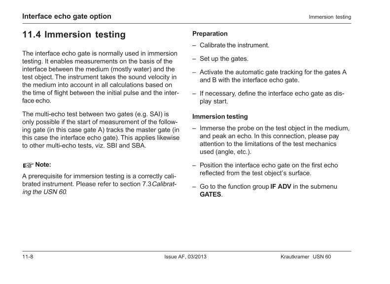
11-8 Issue AF, 03/2013 Krautkramer USN 60
Interface echo gate option
11.4 Immersion testing
The interface echo gate is normally used in immersiontesting. It enables measurements on the basis of theinterface between the medium (mostly water) and thetest object. The instrument takes the sound velocity inthe medium into account in all calculations based onthe time of flight between the initial pulse and the inter-face echo.
The multi-echo test between two gates (e.g. SAI) isonly possible if the start of measurement of the follow-ing gate (in this case gate A) tracks the master gate (inthis case the interface echo gate). This applies likewiseto other multi-echo tests, viz. SBI and SBA.
H Note:
A prerequisite for immersion testing is a correctly cali-brated instrument. Please refer to section 7.3 Calibrat-ing the USN 60.
Preparation
– Calibrate the instrument.
– Set up the gates.
– Activate the automatic gate tracking for the gates Aand B with the interface echo gate.
– If necessary, define the interface echo gate as dis-play start.
Immersion testing
– Immerse the probe on the test object in the medium,and peak an echo. In this connection, please payattention to the limitations of the test mechanicsused (angle, etc.).
– Position the interface echo gate on the first echoreflected from the test object’s surface.
– Go to the function group IF ADV in the submenuGATES.
Immersion testing
Krautkramer USN 60 Issue AF, 03/2013 11-9
Interface echo gate option
– Choose the option IMMERSION for the functionIF DELAY MODE. The USN 60 will now use thesound velocity in the delay medium to calculate thelength of the delay line, the position and the width ofthe interface echo gate.
Corrections
You can vary the sound velocity in the delay line bymeans of the function DELAY VELOCITY. You can cor-rect the time-of-flight measurements based on the pointof measurement in the interface echo gate by means ofthe function IF OFFSET.
H Note:
If you use the function IF OFFSET, you will vary allsound paths based on the point of measurement of theinterface echo gate. You should therefore only vary thissetting if you are familiar with the effects of the varia-tion on the measured values.
– If necessary, use the function DELAY VELOCITY tovary the sound velocity in the medium.
– If necessary, correct the time-of-flight measurementby means of the function IF OFFSET.
– Read the measured values.
Immersion testing
11-10 Issue AF, 03/2013 Krautkramer USN 60
Krautkramer USN 60 Issue AF, 03/2013 12-1
Backwall Echo Attenuation option 12
12-2 Issue AF, 03/2013 Krautkramer USN 60
Backwall Echo Attenuation option Backwall Echo Attenuation
12.1 Backwall Echo Attenuation
The USN 60 can be provided with the Backwall EchoAttenuation option. This option enables the operator toset a separate gain for the gate range of gate B. Thisgain is independent of the gain for the rest of the testrange. The Backwall Echo Attenuation therefore en-ables a selective attenuation or peaking of the echoesin the B gate.
A typical application case for the Backwall EchoAttenuation is forging testing. In this application case,the gain is reduced in gate B until the backwall echo iscompletely displayed in the A-scan. This allows to se-lectively integrate the backwall echo into the flawevaluation.
However, the Backwall Echo Attenuation option alsoallows to systematically increase the gain. The opera-tor can in this way for example only increase the gainwithin the flaw expectancy range in order to peak theecho in this range.
H Note:
The Backwall Echo Attenuation has no effect on theevaluation of the echoes in the B gate. The echo evalu-ation continues to refer to the actually measured sig-nals. All other gate-related functions, such as gatealarm or TTL assignment are not affected by thiseither.

Krautkramer USN 60 Issue AF, 03/2013 12-3
Backwall Echo Attenuation optionThe submenu PLSRCVR
12.2 The submenu PLSRCVR
The submenu PLSRCVR is used for setting pulser andreceiver. With the Backwall Echo Attenuation optioninstalled, you will find the additional function groupBCK ATTN here.
– If necessary, go to the main menu.
– Select the submenu PLSRCVR.
The function group BCK ATTN.You will find all the functions for the attenuation of thebackwall echo in this function group.
– Select the function group BCK ATTN.
12-4 Issue AF, 03/2013 Krautkramer USN 60
Backwall Echo Attenuation option
MODE
This function serves for activating the Backwall EchoAttenuation. If this function is active, all echoes in theB gate are shown with a separate gain.
– Select the function MODE.
– Activate the Backwall Echo Attenuation using theright-hand rotary knob.
BW GAIN
You can set the separate gain for the echoes in gate Bin this function. The gain may be situated both aboveand below the gain in the rest of the test range. Thesetting range for the gain is between 0.0 and 110.0 dB.
H Note:
The gain set here does not affect the evaluation of theechoes in the B gate. The echo evaluation refers to theeffective signals.
– Select the function BW GAIN.
– Use the right-hand rotary knob to set the requiredgain.
The submenu PLSRCVR
Krautkramer USN 60 Issue AF, 03/2013 12-5
Backwall Echo Attenuation option
B START
This function serves for positioning the B gate.
H Note:
When using the Backwall Echo Attenuation, the startmode for gate B can only be set to the initial pulse orthe interface echo, but not to the A gate.
– Select the function B START.
– Position the B gate using the right-hand rotary knob.
GATE B WIDTH
You can use this function to set the width of the Bgate.
H Note:
The gain variation applies to the entire range of the Bgate. This also includes overlapping areas with othergates.
– Select the function GATE B WIDTH.
– Use the right-hand rotary knob to set the requiredwidth.
The submenu PLSRCVR
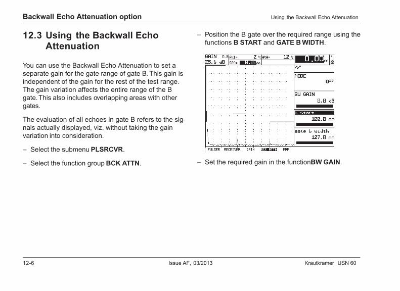
12-6 Issue AF, 03/2013 Krautkramer USN 60
Backwall Echo Attenuation option
12.3 Using the Backwall EchoAttenuation
You can use the Backwall Echo Attenuation to set aseparate gain for the gate range of gate B. This gain isindependent of the gain for the rest of the test range.The gain variation affects the entire range of the Bgate. This also includes overlapping areas with othergates.
The evaluation of all echoes in gate B refers to the sig-nals actually displayed, viz. without taking the gainvariation into consideration.
– Select the submenu PLSRCVR.
– Select the function group BCK ATTN.
– Position the B gate over the required range using thefunctions B START and GATE B WIDTH.
– Set the required gain in the function BW GAIN.
Using the Backwall Echo Attenuation
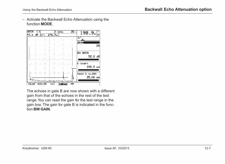
Krautkramer USN 60 Issue AF, 03/2013 12-7
Backwall Echo Attenuation option
– Activate the Backwall Echo Attenuation using thefunction MODE.
The echoes in gate B are now shown with a differentgain from that of the echoes in the rest of the testrange. You can read the gain for the test range in thegain box. The gain for gate B is indicated in the func-tion BW GAIN.
Using the Backwall Echo Attenuation

12-8 Issue AF, 03/2013 Krautkramer USN 60

Krautkramer USN 60 Issue AF, 03/2013 13-1
Documentation 13
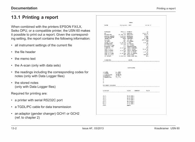
13-2 Issue AF, 03/2013 Krautkramer USN 60
Documentation Printing a report
13.1 Printing a report
When combined with the printers EPSON FX/LX,Seiko DPU, or a compatible printer, the USN 60 makesit possible to print out a report. Given the correspond-ing setting, the report contains the following information:
• all instrument settings of the current file
• the file header
• the memo text
• the A-scan (only with data sets)
• the readings including the corresponding codes fornotes (only with Data Logger files)
• the stored notes(only with Data Logger files)
Required for printing are:
• a printer with serial RS232C port
• a TGDL/PC cable for data transmission
• an adaptor (gender changer) GCH1 or GCH2(ref. to chapter 2)
Krautkramer USN 60 Issue AF, 03/2013 13-3
DocumentationPrinting a report
Preparing for printingBefore you can print out a report, you have to select aprinter and set the data transfer rate (baud rate) ac-cordingly.
– Select the function group PRINTER in the submenuFILES.
– Use the function PRINTER to select the connectedprinter.
– Go to the function group SER COMM in order to setthe baud rate of the RS232 port.
– Select the function BAUD RATE.
– Use the right-hand rotary knob to set the requiredbaud rate.
H Note:
If you have any doubts, go by the technical data of theconnected unit. This is the only way to ensure anerror-free communication.
Configuring the ccccc keyTo print out a report, you have to the set the functionof the c key in such a way that the required dataare output via the RS232 port.
– Select the function group PRINTER in the submenuFILES.
– Use the function PRINTER to select the connectedprinter.
– Set the function COPY MODE to REPORT in orderto output the report via the RS232 port according tothe settings.
PrintingAfter connecting, preparing and activating the printer,just press the c key.
The report is printed out.

13-4 Issue AF, 03/2013 Krautkramer USN 60
Krautkramer USN 60 Issue AF, 03/2013 14-1
Care and maintenance 14
14-2 Issue AF, 03/2013 Krautkramer USN 60
Care and maintenance Care of the instrument
14.1 Care of the instrument
Clean the instrument and its accessories using a moistcloth. Use water or a mild household cleaner.
A Attention:
Do not use any solvents! The plastic parts can bedamaged or embrittled by this.
14.2 Maintaining batteries
Charging the Lithium-Ion storage batteryTo charge the Lithium-Ion storage battery LIA 60, youneed the special power supply/charger unit UN 670.
The standard package of the charger unit includes abrief operating manual describing the charging proce-dure. Please read this description before connectingthe charger unit.
H Note:
You can charge the Lithium-Ion storage battery duringnormal operation. You don’t have to remove the batterylid for this purpose but only connect the charger unitwith the connection on the battery lid.
You can charge a separate Lithium-Ion storage batteryby connecting it (or the battery lid) to the charger unit.The battery lid does not have to be installed on theUSN 60 for this purpose.

Krautkramer USN 60 Issue AF, 03/2013 14-3
Care and maintenanceMaintaining batteries
Charging NiMH storage batteriesYou can use the charger unit UN 665 to charge NiMHstorage batteries.
A Attention:
Do only use batteries and battery charger recom-mended by us. Any improper handling of batteries andcharger may cause an explosion hazard.
Charging of partially discharged NiMH batteries
If batteries are only partially discharged (less than 50 %of operating time), the full capacity is not reached bynormal charging.
– Start by fully discharging the batteries.You can use the discharging function of the batterycharger for this. For more details, please read thenotes on the operation of the battery charger.
– The batteries are automatically charged after that.
Charging of exhausted NiMH batteries
If batteries are exhausted, e.g. after a prolonged storagetime in empty state, they often reach their full capacityonly after repeated discharge/charge cycles.
The charger identifies defective batteries. In that case,replace the batteries by a new set. Otherwise there isthe danger that individual cells have different capacitiesso that you will no longer obtain the normal operatingtime with the instrument in battery operation.
Care of NiMH batteriesCapacity and life of batteries mainly depend on thecorrect handling. Please therefore observe the tipsbelow.
You should charge batteries in the following cases:
• before the initial startup
• after a storage time of 3 months or longer
• after frequent partial discharge
14-4 Issue AF, 03/2013 Krautkramer USN 60
Care and maintenance
How to handle alkaline batteries– Please remove the batteries from the instrument if it
has not been operated for a longer time.
A Attention:
Leaking batteries may cause severe damages to theinstrument! You should always only use leak-proofbatteries and remove them from the instrument afterturning it off.
H Note:
Used batteries are special waste and have to bedisposed of according to legal requirements!
In the interest of environmental protection, we recom-mend that you only use rechargeable batteries.
Maintaining batteries
14.3 Maintenance
The USN 60 requires basically no maintenance.
A Attention:
Repair work may only be carried out by members ofauthorized GE Inspection Technologies Service staff.

Krautkramer USN 60 Issue AF, 03/2013 15-1
Interfaces and peripherals 15
15-2 Issue AF, 03/2013 Krautkramer USN 60
Interfaces and Peripherals
15.1 Interfaces
Serial RS232 portThe 7-pin connector socket on the rear panel of theUSN 60 is the bidirectional RS232 port. It serves for thedata transmission to an external unit, e.g. to a printer orPC.
The USN 60 can also receive data transferred from aPC. All key controls and functions are accessible.
Test reports and other data are transferred by means ofthe c key. The COPY MODE function defines theway the USN 60 reacts when a key is pressed.
This table gives an overview of the RS232 output op-tions of the USN 60.
Interfaces
COPY MODE Output
REPORT A complete test report includingall data according to the se-lected settings.
PARADUMP A list including all functionsavailable, as well as parametersand remote control codes thatcan be set.
LOG TO PORT The reading displayed in thelarge display box.
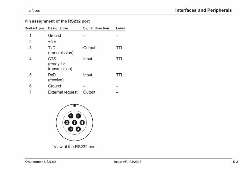
Krautkramer USN 60 Issue AF, 03/2013 15-3
Interfaces and PeripheralsInterfaces
Pin assignment of the RS232 portContact pin Designation Signal direction Level
1 Ground – –2 +5 V – –3 TxD Output TTL
(transmission)4 CTS Input TTL
(ready fortransmission)
5 RxD Input TTL(receive)
6 Ground – –7 External request Output –
View of the RS232 port
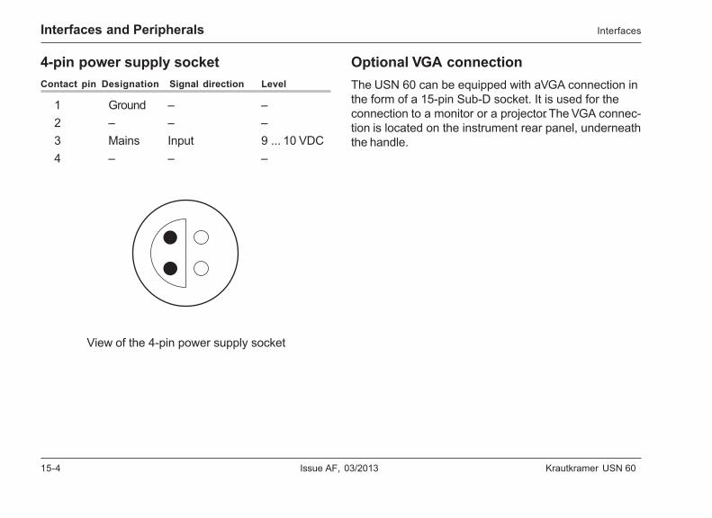
15-4 Issue AF, 03/2013 Krautkramer USN 60
Interfaces and Peripherals
4-pin power supply socketContact pin Designation Signal direction Level
1 Ground – –2 – – –3 Mains Input 9 ... 10 VDC4 – – –
View of the 4-pin power supply socket
Optional VGA connectionThe USN 60 can be equipped with a VGA connection inthe form of a 15-pin Sub-D socket. It is used for theconnection to a monitor or a projector. The VGA connec-tion is located on the instrument rear panel, underneaththe handle.
Interfaces
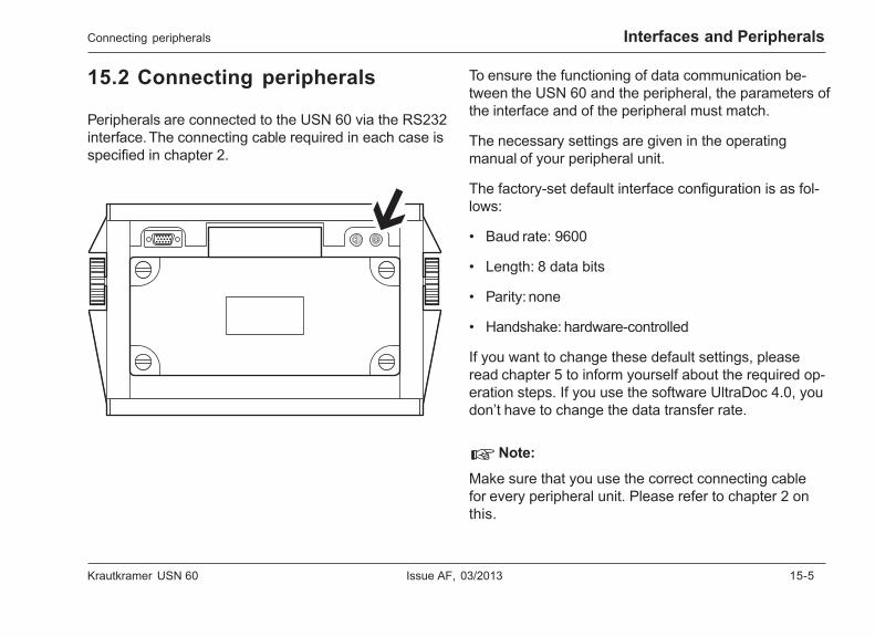
Krautkramer USN 60 Issue AF, 03/2013 15-5
Interfaces and PeripheralsConnecting peripherals
15.2 Connecting peripherals
Peripherals are connected to the USN 60 via the RS232interface. The connecting cable required in each case isspecified in chapter 2.
To ensure the functioning of data communication be-tween the USN 60 and the peripheral, the parameters ofthe interface and of the peripheral must match.
The necessary settings are given in the operatingmanual of your peripheral unit.
The factory-set default interface configuration is as fol-lows:
• Baud rate: 9600
• Length: 8 data bits
• Parity: none
• Handshake: hardware-controlled
If you want to change these default settings, pleaseread chapter 5 to inform yourself about the required op-eration steps. If you use the software UltraDoc 4.0, youdon’t have to change the data transfer rate.
H Note:
Make sure that you use the correct connecting cablefor every peripheral unit. Please refer to chapter 2 onthis.
15-6 Issue AF, 03/2013 Krautkramer USN 60
Interfaces and Peripherals
15.3 Data transfer
Transferring data to a PCThe USN 60 enables you to transfer data to a PC viathe RS232 interface. You can select the data to betransferred by means of the function COPY MODE. Thedata are automatically formatted and transferred asASCII text.
The optional utility program UltraDOC 4.0 makes thedata transfer to a PC easier (please see chapter 2).
– Connect the RS232 interface of the USN 60 with theserial port of your PC by means of a suitable cable.
– Use the function COPY MODE to select the data tobe transferred.
– Press the c key to start the data transfer.
The keyboard remains disabled till the end of the datatransfer.
Transfer formatsPlease find an overview of the data formats for transfer-ring single readings on the following page. The data for-mat depends on the selected units and on the resolu-tion:
X.XXX IN: Units INCH,1 place before,2 places after the decimal point
XX.XX IN: Units INCH,2 places before,2 places after the decimal point
XX.XX MM: Units MM2 places before,2 places after the decimal point
XXX.X MM: Units MM3 places before,1 place after the decimal point
Data transfer

Krautkramer USN 60 Issue AF, 03/2013 15-7
Interfaces and Peripherals
Space Blank spaceX digits 0-9. decimal pointIN Units INCHMM Units MMCR Carriage ReturnLF Line Feed
.oN-etyB 1 2 3 4 5 6 7 8 9 01 11 21 31
NIXXX.XtamroFataD knalb X . X X X knalb I N knalb knalb RC FL
NIXX.XXtamroFataD knalb X X . X X knalb I N knalb knalb RC FL
MMXX.XXtamroFataD knalb X X . X X knalb M M knalb knalb RC FL
MMXX.XXtamroFataD knalb X X X . X knalb M M knalb knalb RC FL
Data transfer
15-8 Issue AF, 03/2013 Krautkramer USN 60
Interfaces and Peripherals
15.4 Remote control
You can remotely control the USN 60 by means of aconnected PC.
The data transfer is carried out by means of a terminalprogram and the corresponding remote control codes.These commands represent instructions referring to theindividual functions of the USN 60.
The possible terminal programs used under DOS in-clude e.g. the Crosstalk program. You can use for ex-ample the program HyperTerminal under Windows.
The commands are input via computer keyboard afterstarting the remote control program and after configur-ing the program interface. In this process, a differenceshould be made between:
• Inquiry of the value or status of a function by meansof the command structure:
<ESC><COMMAND><RETURN>
The USN 60 will then send the value of the currentsetting.
• Input of a new value or status of a function bymeans of the command structure:<ESC><COMMAND><SPACE><VALUE><RETURN>
All values are input or sent by the USN 60 without adecimal point. It is therefore necessary to observe theresolution of the function in question with all values.The resolution of a function applies to the completevalue range of the function.
A resolution of 0.01 means:
The USN 60 sends the value of a function multiplied bythe factor of 100. When a value is input, it must bemultiplied by the factor of 100.
Examples:
• Setting of the display delay to 72.39 mm:
<ESC>dd 7239<RETURN>
• Setting of the display width to 72.3 mm:
<ESC>dw 7230<RETURN>
• Setting of the display width to 192 mm:
<ESC>dw 19200<RETURN>
Remote control
Krautkramer USN 60 Issue AF, 03/2013 15-9
Interfaces and Peripherals
A resolution of 0.1 means:
The USN 60 sends the value of a function multiplied bythe factor of 10. When a value is input, it must be multi-plied by the factor of 10.
Example:
• Setting of the gain to 51.5 dB
<ESC>db 515<RETURN>
A resolution of 1 means:
The USN 60 sends the value of a function without anymultiplication. A value must be input without multiplica-tion.
Example:
• Setting of the threshold of the A gate to 41 %:
<ESC>at 41<RETURN>
Remote control
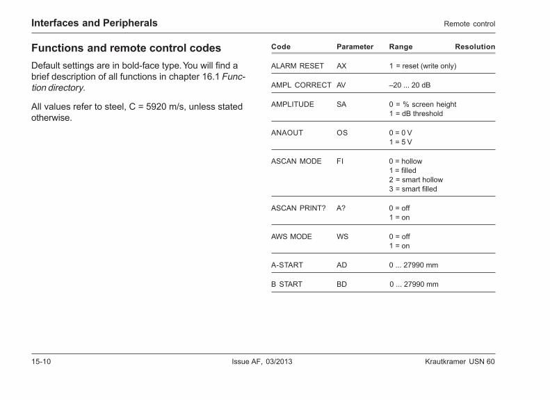
15-10 Issue AF, 03/2013 Krautkramer USN 60
Interfaces and Peripherals
Functions and remote control codesDefault settings are in bold-face type. You will find abrief description of all functions in chapter 16.1 Func-tion directory.
All values refer to steel, C = 5920 m/s, unless statedotherwise.
Code Parameter Range Resolution
ALARM RESET AX 1 = reset (write only)
AMPL CORRECT AV –20 ... 20 dB
AMPLITUDE SA 0 = % screen height1 = dB threshold
ANAOUT OS 0 = 0 V1 = 5 V
ASCAN MODE FI 0 = hollow1 = filled2 = smart hollow3 = smart filled
ASCAN PRINT? A? 0 = off1 = on
AWS MODE WS 0 = off1 = on
A-START AD 0 ... 27990 mm
B START BD 0 ... 27990 mm
Remote control
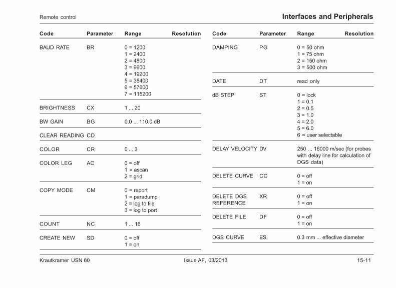
Krautkramer USN 60 Issue AF, 03/2013 15-11
Interfaces and Peripherals
Code Parameter Range Resolution
BAUD RATE BR 0 = 12001 = 24002 = 48003 = 96004 = 192005 = 384006 = 576007 = 115200
BRIGHTNESS CX 1 ... 20
BW GAIN BG 0.0 ... 110.0 dB
CLEAR READING CD
COLOR CR 0 ... 3
COLOR LEG AC 0 = off1 = ascan2 = grid
COPY MODE CM 0 = report1 = paradump2 = log to file3 = log to port
COUNT NC 1 ... 16
CREATE NEW SD 0 = off1 = on
Code Parameter Range Resolution
DAMPING PG 0 = 50 ohm1 = 75 ohm2 = 150 ohm3 = 500 ohm
DATE DT read only
dB STEP ST 0 = lock1 = 0.12 = 0.53 = 1.04 = 2.05 = 6.06 = user selectable
DELAY VELOCITY DV 250 ... 16000 m/sec (for probeswith delay line for calculation ofDGS data)
DELETE CURVE CC 0 = off1 = on
DELETE DGS XR 0 = offREFERENCE 1 = on
DELETE FILE DF 0 = off1 = on
DGS CURVE ES 0.3 mm ... effective diameter
Remote control
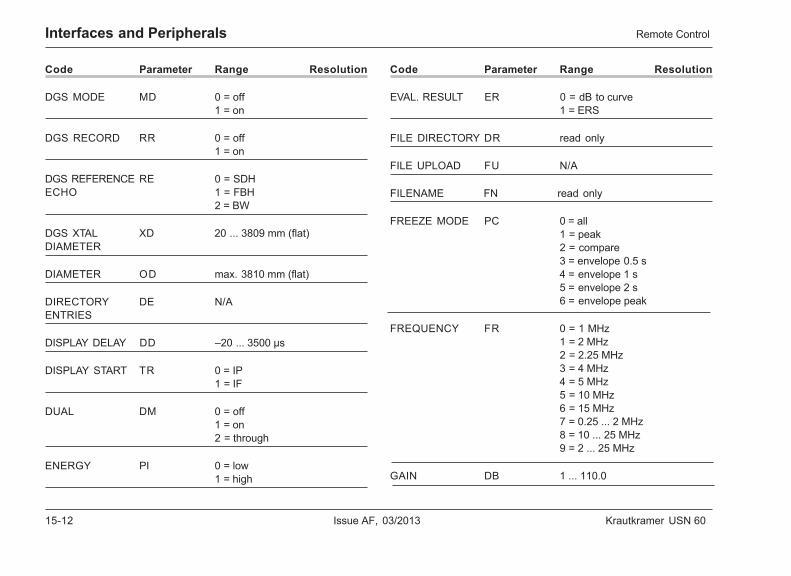
15-12 Issue AF, 03/2013 Krautkramer USN 60
Interfaces and Peripherals Remote Control
Code Parameter Range Resolution
DGS MODE MD 0 = off1 = on
DGS RECORD RR 0 = off1 = on
DGS REFERENCE RE 0 = SDHECHO 1 = FBH
2 = BW
DGS XTAL XD 20 ... 3809 mm (flat)DIAMETER
DIAMETER OD max. 3810 mm (flat)
DIRECTORY DE N/AENTRIES
DISPLAY DELAY DD –20 ... 3500 µs
DISPLAY START TR 0 = IP1 = IF
DUAL DM 0 = off1 = on2 = through
ENERGY PI 0 = low1 = high
Code Parameter Range Resolution
EVAL. RESULT ER 0 = dB to curve1 = ERS
FILE DIRECTORY DR read only
FILE UPLOAD FU N/A
FILENAME FN read only
FREEZE MODE PC 0 = all1 = peak2 = compare3 = envelope 0.5 s4 = envelope 1 s5 = envelope 2 s6 = envelope peak
FREQUENCY FR 0 = 1 MHz1 = 2 MHz2 = 2.25 MHz3 = 4 MHz4 = 5 MHz5 = 10 MHz6 = 15 MHz7 = 0.25 ... 2 MHz8 = 10 ... 25 MHz9 = 2 ... 25 MHz
GAIN DB 1 ... 110.0
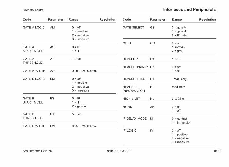
Krautkramer USN 60 Issue AF, 03/2013 15-13
Interfaces and Peripherals
Code Parameter Range Resolution
GATE A LOGIC AM 0 = off1 = positive2 = negative3 = measure
GATE A AS 0 = IPSTART MODE 1 = IF
GATE A AT 5 ... 90THRESHOLD.
GATE A WIDTH AW 0.25 ... 28000 mm
GATE B LOGIC BM 0 = off1 = positive2 = negative3 = measure
GATE B BS 0 = IPSTART MODE 1 = IF
2 = gate A
GATE B BT 5 ... 90THRESHOLD.
GATE B WIDTH BW 0.25 ... 28000 mm
Code Parameter Range Resolution
GATE SELECT GS 0 = gate A1 = gate B2 = IF gate
GRID GR 0 = off1 = cross2 = grat
HEADER # H# 1 ... 9
HEADER PRINT? H? 0 = off1 = on
HEADER TITLE HT read only
HEADER HI read onlyINFORMATION
HIGH LIMIT HL 0 ... 28 m
HORN AH 0 = on1 = off
IF DELAY MODE MI 0 = contact1 = immersion
IF LOGIC IM 0 = off1 = positive2 = negative3 = measure
Remote control
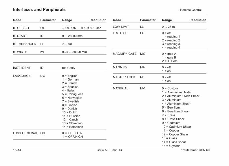
15-14 Issue AF, 03/2013 Krautkramer USN 60
Interfaces and Peripherals Remote Control
Code Parameter Range Resolution
IF OFFSET OF –999.9997 ... 999.9997 µsec
IF START IS 0 ... 28000 mm
IF THRESHOLD IT 5 ... 90
IF WIDTH IW 0.25 ... 28000 mm
INST IDENT ID read only
LANGUAGE DG 0 = English1 = German2 = French3 = Spanish4 = Italian5 = Portuguese6 = Norwegian7 = Swedish8 = Finnish9 = Danish10 = Dutch11 = Russian12 = Czech13 = Slovenian14 = Romanian
LOSS OF SIGNAL OS 0 = OFF/LOW 1 = OFF/HIGH
Code Parameter Range Resolution
LOW LIMIT LL 0 ... 28 m
LRG DISP. LC 0 = off1 = reading 12 = reading 23 = reading 34 = reading 4
MAGNIFY GATE MG 0 = gate A1 = gate B2 = IF Gate
MAGNIFY MA 0 = off1 = on
MASTER LOCK ML 0 = off1 = on
MATERIAL MV 0 = Custom1 = Aluminium Oxide2 = Aluminium Oxide Shear3 = Aluminium4 = Aluminium Shear5 = Beryllium6 = Beryllium Shear7 = Brass8 = Brass Shear9 = Cadmium10 = Cadmium Shear11 = Copper12 = Copper Shear13 = Glass14 = Glass Shear15 = Glycerin
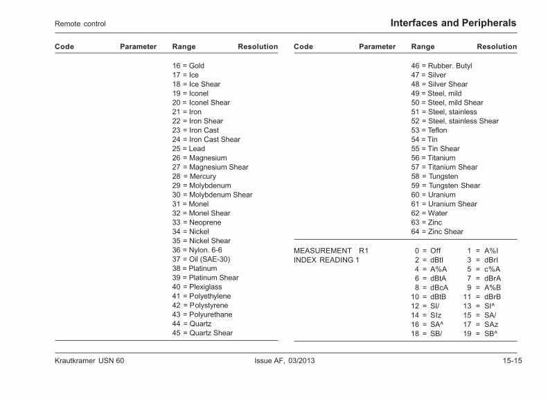
Krautkramer USN 60 Issue AF, 03/2013 15-15
Interfaces and Peripherals
Code Parameter Range Resolution
16 = Gold17 = Ice18 = Ice Shear19 = Iconel20 = Iconel Shear21 = Iron22 = Iron Shear23 = Iron Cast24 = Iron Cast Shear25 = Lead26 = Magnesium27 = Magnesium Shear28 = Mercury29 = Molybdenum30 = Molybdenum Shear31 = Monel32 = Monel Shear33 = Neoprene34 = Nickel35 = Nickel Shear36 = Nylon. 6-637 = Oil (SAE-30)38 = Platinum39 = Platinum Shear40 = Plexiglass41 = Polyethylene42 = Polystyrene43 = Polyurethane44 = Quartz45 = Quartz Shear
Code Parameter Range Resolution
46 = Rubber. Butyl47 = Silver48 = Silver Shear49 = Steel, mild50 = Steel, mild Shear51 = Steel, stainless52 = Steel, stainless Shear53 = Teflon54 = Tin55 = Tin Shear56 = Titanium57 = Titanium Shear58 = Tungsten59 = Tungsten Shear60 = Uranium61 = Uranium Shear62 = Water63 = Zinc64 = Zinc Shear
MEASUREMENT R1 0 = Off 1 = A%IINDEX READING 1 2 = dBtI 3 = dBrI
4 = A%A 5 = c%A6 = dBtA 7 = dBrA8 = dBcA 9 = A%B
10 = dBtB 11 = dBrB12 = SI/ 13 = SI^14 = SIz 15 = SA/16 = SA^ 17 = SAz18 = SB/ 19 = SB^
Remote control

15-16 Issue AF, 03/2013 Krautkramer USN 60
Interfaces and Peripherals
Code Parameter Range Resolution
20 = SBz 21 = SA/I/22 = SA^I/ 23 = SAzI/24 = SA/I^ 25 = SA^I^26 = SAzI^ 27 = SA/Iz28 = SA^Iz 29 = SAzIz30 = SB/I/ 31 = SB^I/32 = SBzI/ 33 = SB/I^34 = SB^I^ 35 = SBzI^36 = SB/Iz 37 = SB^Iz38 = SBzIz 39 = SB/A/40 = SB/A^ 41 = SB/Az42 = SB^A/ 43 = SB^A^44 = SB^Az 45 = SBzA/46 = SBzA^ 47 = SBzAz48 = DI/ 49 = DI^50 = DIz 51 = DA/52 = DA^ 53 = DAz54 = DB/ 55 = DB^56 = DBz 57 = DA/I/58 = DA^I/ 59 = DAzI/60 = DA/I^ 61 = DA^I^62 = DAzI^ 63 = DA/Iz64 = DA^Iz 65 = DAzIz66 = DB/I/ 67 = DB^I/68 = DBzI/ 69 = DB/I^70 = DB^I^ 71 = DBzI^72 = DB/Iz 73 = DB^Iz74 = DBzIz 75 = DB/A/76 = DB/A^ 77 = DB/Az78 = DB^A/ 79 = DB^A^80 = DB^Az 81 = DBzA/
Code Parameter Range Resolution
82 = DBzA^ 83 = DBzAz84 = PI/ 85 = PI^86 = PIz 87 = PA/88 = PA^ 89 = PAz90 = PB/ 91 = PB^92 = PBz 93 = PA/I/94 = PA^I/ 95 = PAzI/96 = PA/I^ 97 = PA^I^98 = PAzI^ 99 = PA/Iz
100 = PA^Iz 101 = PAzIz102 = PB/I/ 103 = PB^I/104 = PBzI/ 105 = PB/I^106 = PB^I^ 107 = PBzI^108 = PB/Iz 109 = PB^Iz110 = PBzIz 111 = PB/A/112 = PB/A^ 113 = PB/Az114 = PB^A/ 115 = PB^A^116 = PB^Az 117 = PBzA/118 = PBzA^ 119 = PBzAz120 = RI/ 121 = RI^122 = RIz 123 = RA/124 = RA^ 125 = RAz126 = RB/ 127 = RB^128 = RBz 129 = RA/I/130 = RA^I/ 131 = RAzI/132 = RA/I^ 133 = RA^I^134 = RAzI^ 135 = RA/Iz136 = RA^Iz 137 = RAzIz138 = RB/I/ 139 = RB^I/140 = RBzI/ 192 = RawA193 = RawB 194 = IFDT
Remote control
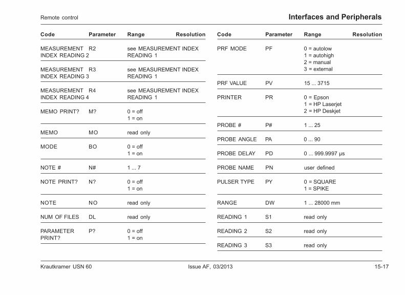
Krautkramer USN 60 Issue AF, 03/2013 15-17
Interfaces and Peripherals
Code Parameter Range Resolution
MEASUREMENT R2 see MEASUREMENT INDEXINDEX READING 2 READING 1
MEASUREMENT R3 see MEASUREMENT INDEXINDEX READING 3 READING 1
MEASUREMENT R4 see MEASUREMENT INDEXINDEX READING 4 READING 1
MEMO PRINT? M? 0 = off1 = on
MEMO MO read only
MODE BO 0 = off1 = on
NOTE # N# 1 ... 7
NOTE PRINT? N? 0 = off1 = on
NOTE NO read only
NUM OF FILES DL read only
PARAMETER P? 0 = offPRINT? 1 = on
Code Parameter Range Resolution
PRF MODE PF 0 = autolow1 = autohigh2 = manual3 = external
PRF VALUE PV 15 ... 3715
PRINTER PR 0 = Epson1 = HP Laserjet2 = HP Deskjet
PROBE # P# 1 ... 25
PROBE ANGLE PA 0 ... 90
PROBE DELAY PD 0 ... 999.9997 µs
PROBE NAME PN user defined
PULSER TYPE PY 0 = SQUARE1 = SPIKE
RANGE DW 1 ... 28000 mm
READING 1 S1 read only
READING 2 S2 read only
READING 3 S3 read only
Remote control
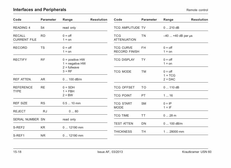
15-18 Issue AF, 03/2013 Krautkramer USN 60
Interfaces and Peripherals
Code Parameter Range Resolution
READING 4 S4 read only
RECALL RD 0 = offCURRENT FILE 1 = on
RECORD TS 0 = off1 = on
RECTIFY RF 0 = positive HW1 = negative HW2 = fullwave3 = RF
REF ATTEN. AR 0 ... 100 dB/m
REFERENCE RE 0 = SDHTYPE 1 = FBH
2 = BW
REF SIZE RS 0.5 ... 10 mm
REJECT RJ 0 ... 80
SERIAL NUMBER SN read only
S-REF2 KR 0 ... 12190 mm
S-REF1 NR 0 ... 12190 mm
Code Parameter Range Resolution
TCG AMPLITUDE TV 0 ... 210 dB
TCG TN –40 ... +40 dB per µsATTENUATION
TCG CURVE FH 0 = offRECORD FINISH 1 = on
TCG DISPLAY TY 0 = off1 = on
TCG MODE TM 0 = off1 = TCG2 = DAC
TCG OFFSET TO 0 ... 110 dB
TCG POINT PT 1 ... 16
TCG START SM 0 = IPMODE 1 = IF
TCG TIME TT 0 ... 28 m
TEST ATTEN DN 0 ... 100 dB/m
THICKNESS TH 1 ... 28000 mm
Remote control
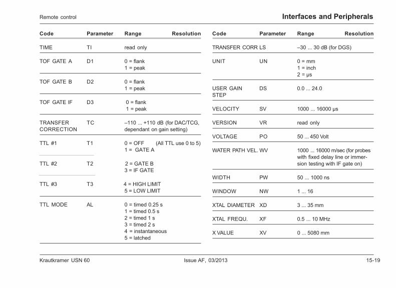
Krautkramer USN 60 Issue AF, 03/2013 15-19
Interfaces and PeripheralsRemote control
Code Parameter Range Resolution
TIME TI read only
TOF GATE A D1 0 = flank1 = peak
TOF GATE B D2 0 = flank1 = peak
TOF GATE IF D3 0 = flank 1 = peak
TRANSFER TC –110 ... +110 dB (for DAC/TCG,CORRECTION dependant on gain setting)
TTL #1 T1 0 = OFF (All TTL use 0 to 5)1 = GATE A
TTL #2 T2 2 = GATE B 3 = IF GATE
TTL #3 T3 4 = HIGH LIMIT5 = LOW LIMIT
TTL MODE AL 0 = timed 0.25 s1 = timed 0.5 s2 = timed 1 s3 = timed 2 s4 = instantaneous5 = latched
Code Parameter Range Resolution
TRANSFER CORR LS –30 ... 30 dB (for DGS)
UNIT UN 0 = mm1 = inch2 = µs
USER GAIN DS 0.0 ... 24.0STEP
VELOCITY SV 1000 ... 16000 µs
VERSION VR read only
VOLTAGE PO 50 ... 450 Volt
WATER PATH VEL. WV 1000 ... 16000 m/sec (for probeswith fixed delay line or immer-sion testing with IF gate on)
WIDTH PW 50 ... 1000 ns
WINDOW NW 1 ... 16
XTAL DIAMETER XD 3 ... 35 mm
XTAL FREQU. XF 0.5 ... 10 MHz
X VALUE XV 0 ... 5080 mm
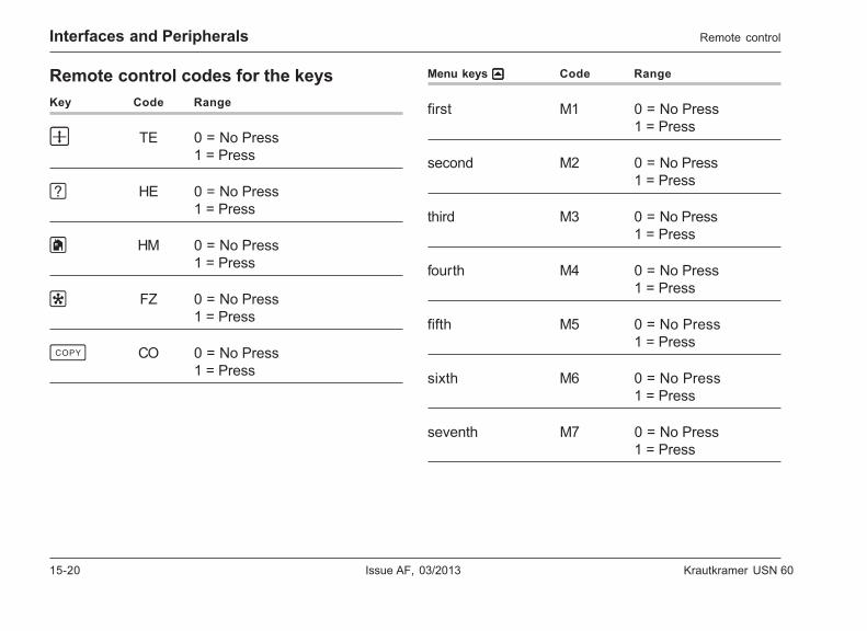
15-20 Issue AF, 03/2013 Krautkramer USN 60
Interfaces and Peripherals
Remote control codes for the keysKey Code Range
w TE 0 = No Press1 = Press
? HE 0 = No Press1 = Press
h HM 0 = No Press1 = Press
f FZ 0 = No Press1 = Press
c CO 0 = No Press1 = Press
Remote control
Menu keys uuuuu Code Range
first M1 0 = No Press1 = Press
second M2 0 = No Press1 = Press
third M3 0 = No Press1 = Press
fourth M4 0 = No Press1 = Press
fifth M5 0 = No Press1 = Press
sixth M6 0 = No Press1 = Press
seventh M7 0 = No Press1 = Press
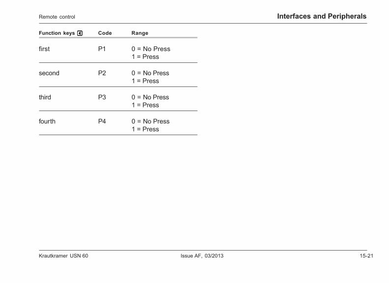
Krautkramer USN 60 Issue AF, 03/2013 15-21
Interfaces and Peripherals
Function keys vvvvv Code Range
first P1 0 = No Press1 = Press
second P2 0 = No Press1 = Press
third P3 0 = No Press1 = Press
fourth P4 0 = No Press1 = Press
Remote control

15-22 Issue AF, 03/2013 Krautkramer USN 60
Interfaces and Peripherals
15.5 Analog outputs
On the rear panel of USN 60 you will find a 15-way Sub-D socket that makes analog switching and control volt-ages available with a corresponding instrument setting.The cable UN 65, provided with a Sub-D plug on the in-strument side, is used as an accessory part for analogvoltage operations. There is no plug on the user side.Please use the connections as required according tothe opposite table:
Analog outputs
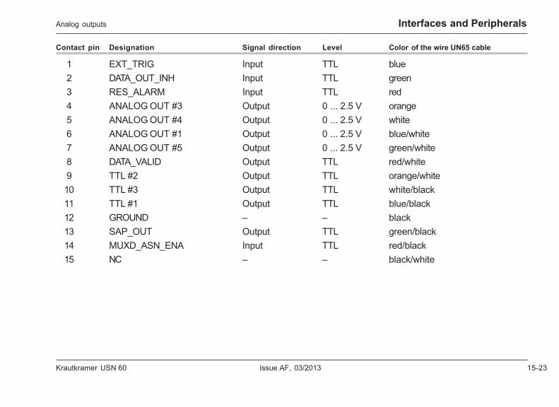
Krautkramer USN 60 Issue AF, 03/2013 15-23
Interfaces and Peripherals
Contact pin Designation Signal direction Level Color of the wire UN65 cable
1 EXT_TRIG Input TTL blue2 DATA_OUT_INH Input TTL green3 RES_ALARM Input TTL red4 ANALOG OUT #3 Output 0 ... 2.5 V orange5 ANALOG OUT #4 Output 0 ... 2.5 V white6 ANALOG OUT #1 Output 0 ... 2.5 V blue/white7 ANALOG OUT #5 Output 0 ... 2.5 V green/white8 DATA_VALID Output TTL red/white9 TTL #2 Output TTL orange/white10 TTL #3 Output TTL white/black11 TTL #1 Output TTL blue/black12 GROUND – – black13 SAP_OUT Output TTL green/black14 MUXD_ASN_ENA Input TTL red/black15 NC – – black/white
Analog outputs
15-24 Issue AF, 03/2013 Krautkramer USN 60
Interfaces and Peripherals
Signal description
External trigger input (EXT_TRIG)
An external triggering of the USN 60 is only available inspike mode, i.e. PULSER TYPE = SPIKE.
The rising flank of the signal triggers the start of thenext cycle. After 35 µs, the pulser sends the first pulse.
The USN 60 takes only signals into consideration thatshow a low level before the rise for at least 4 ns andafterwards have “high level” for at least 40 ns.
H Note:
The external trigger signal only starts a new cycle if theoption EXTERNAL is selected for the functionPRF MODE (only possible for PULSER TYPE =SPIKE).
Test data release (DATA_OUT_INH)
All outputs are activated with the rising flank.
Analog outputs
Alarm acknowledgement (RES_ALARM)
The alarms at the TTL outputs are reset with the risingflank.
H Note:
Alarms are only reset if the option LATCHED is se-lected for the function MODE.
Analog outputs 1 ... 4 (ANALOG OUT #1 ... 4)
The output voltage is proportional to the reading dis-played in the corresponding display box. It correspondseither to the amplitude of the highest echo within thecorresponding gate or to the measured wall thickness(time of flight).
If an amplitude is displayed in the display box, themaximum signal voltage of 2.5 V corresponds to anamplitude of 100 % screen height. A voltage of 0 V cor-responds to 0 % screen height.
If a wall thickness is displayed in the display box, thenthe maximum signal voltage of 2.5 V corresponds tothe largest wall thickness that can be displayed on thescreen. A voltage of 0 V corresponds to the smallestwall thickness that can be displayed on the screen, i.e.to the value in DISPLAY DELAY.
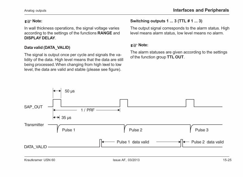
Krautkramer USN 60 Issue AF, 03/2013 15-25
Interfaces and Peripherals
H Note:
In wall thickness operations, the signal voltage variesaccording to the settings of the functions RANGE andDISPLAY DELAY.
Data valid (DATA_VALID)
The signal is output once per cycle and signals the va-lidity of the data. High level means that the data are stillbeing processed. When changing from high level to lowlevel, the data are valid and stable (please see figure).
Switching outputs 1 ... 3 (TTL # 1 ... 3)
The output signal corresponds to the alarm status. Highlevel means alarm status, low level means no alarm.
H Note:
The alarm statuses are given according to the settingsof the function group TTL OUT.
Analog outputs

15-26 Issue AF, 03/2013 Krautkramer USN 60
Interfaces and Peripherals
Transmitter trigger pulse (SAP_OUT)
A transmitter trigger pulse is output here for 50 psec atthe start of every cycle. The pulser sends the first initialpulse 35 psec after changing to the high level (pleasesee figure on the preceding page).
MUXD synchronization (MUXD_ASN_ENA)
A signal from the MUXD multiplexer from GE Inspec-tion Technologies can be recorded at this input. The sig-nal serves for transmitting the channel from the MUXDprovided for the display in the USN 60.
Analog outputs
Krautkramer USN 60 Issue AF, 03/2013 16-1
Appendix 16
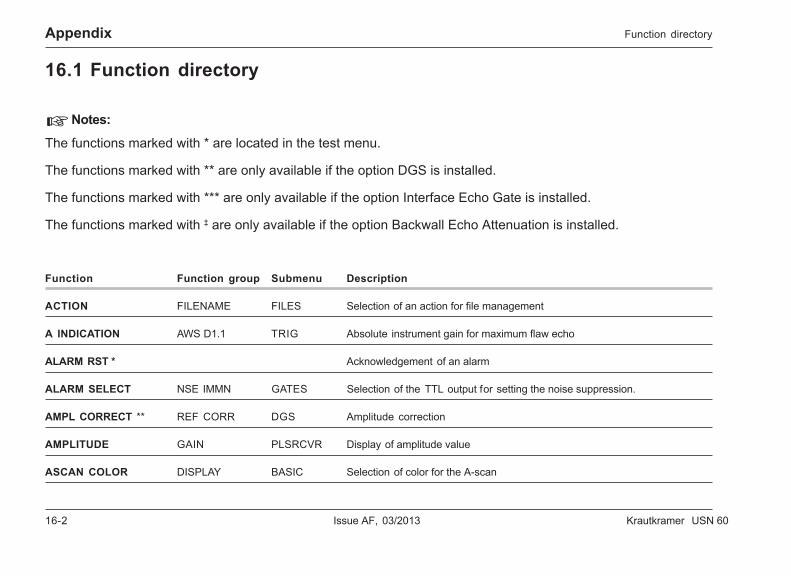
16-2 Issue AF, 03/2013 Krautkramer USN 60
Appendix
16.1 Function directory
H Notes:
The functions marked with * are located in the test menu.
The functions marked with ** are only available if the option DGS is installed.
The functions marked with *** are only available if the option Interface Echo Gate is installed.
The functions marked with ‡ are only available if the option Backwall Echo Attenuation is installed.
Function Function group Submenu Description
ACTION FILENAME FILES Selection of an action for file management
A INDICATION AWS D1.1 TRIG Absolute instrument gain for maximum flaw echo
ALARM RST * Acknowledgement of an alarm
ALARM SELECT NSE IMMN GATES Selection of the TTL output for setting the noise suppression.
AMPL CORRECT ** REF CORR DGS Amplitude correction
AMPLITUDE GAIN PLSRCVR Display of amplitude value
ASCAN COLOR DISPLAY BASIC Selection of color for the A-scan
Function directory
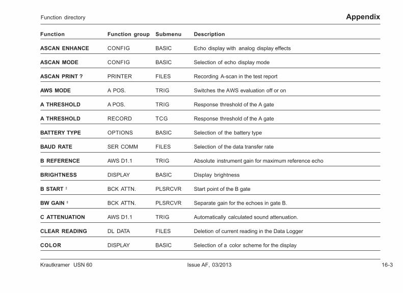
Krautkramer USN 60 Issue AF, 03/2013 16-3
Appendix
Function Function group Submenu Description
ASCAN ENHANCE CONFIG BASIC Echo display with analog display effects
ASCAN MODE CONFIG BASIC Selection of echo display mode
ASCAN PRINT ? PRINTER FILES Recording A-scan in the test report
AWS MODE A POS. TRIG Switches the AWS evaluation off or on
A THRESHOLD A POS. TRIG Response threshold of the A gate
A THRESHOLD RECORD TCG Response threshold of the A gate
BATTERY TYPE OPTIONS BASIC Selection of the battery type
BAUD RATE SER COMM FILES Selection of the data transfer rate
B REFERENCE AWS D1.1 TRIG Absolute instrument gain for maximum reference echo
BRIGHTNESS DISPLAY BASIC Display brightness
B START ‡ BCK ATTN. PLSRCVR Start point of the B gate
BW GAIN ‡ BCK ATTN. PLSRCVR Separate gain for the echoes in gate B.
C ATTENUATION AWS D1.1 TRIG Automatically calculated sound attenuation.
CLEAR READING DL DATA FILES Deletion of current reading in the Data Logger
COLOR DISPLAY BASIC Selection of a color scheme for the display
Function directory
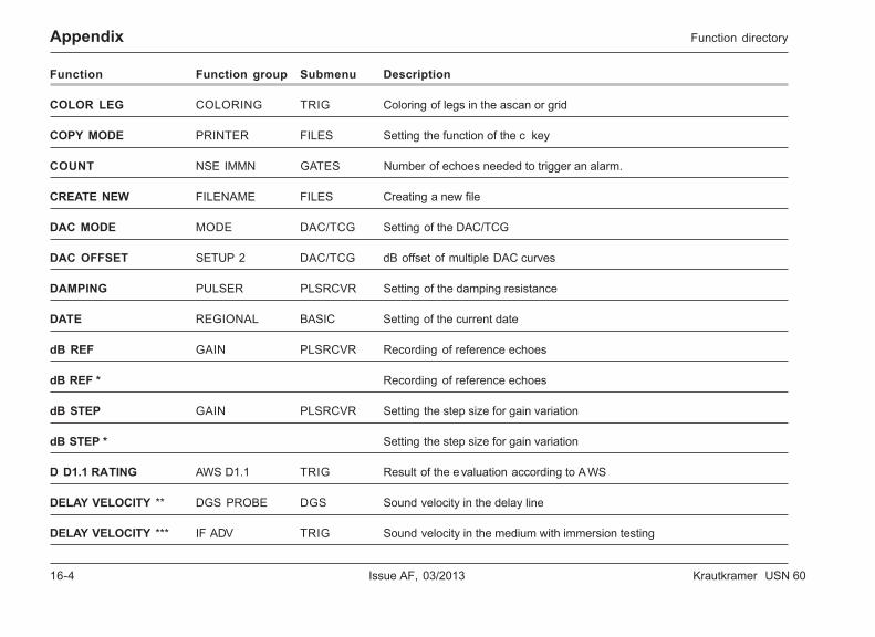
16-4 Issue AF, 03/2013 Krautkramer USN 60
Appendix Function directory
Function Function group Submenu Description
COLOR LEG COLORING TRIG Coloring of legs in the ascan or grid
COPY MODE PRINTER FILES Setting the function of the c key
COUNT NSE IMMN GATES Number of echoes needed to trigger an alarm.
CREATE NEW FILENAME FILES Creating a new file
DAC MODE MODE DAC/TCG Setting of the DAC/TCG
DAC OFFSET SETUP 2 DAC/TCG dB offset of multiple DAC curves
DAMPING PULSER PLSRCVR Setting of the damping resistance
DATE REGIONAL BASIC Setting of the current date
dB REF GAIN PLSRCVR Recording of reference echoes
dB REF * Recording of reference echoes
dB STEP GAIN PLSRCVR Setting the step size for gain variation
dB STEP * Setting the step size for gain variation
D D1.1 RATING AWS D1.1 TRIG Result of the e valuation according to AWS
DELAY VELOCITY ** DGS PROBE DGS Sound velocity in the delay line
DELAY VELOCITY *** IF ADV TRIG Sound velocity in the medium with immersion testing
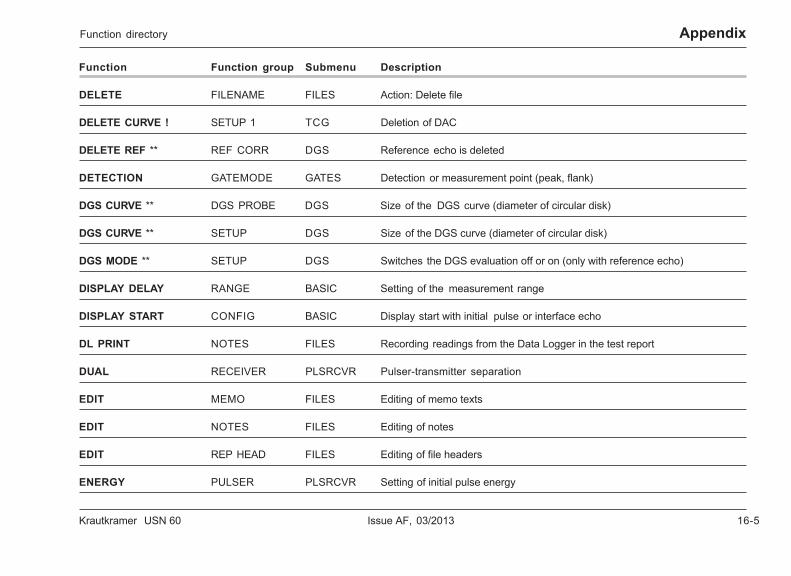
Krautkramer USN 60 Issue AF, 03/2013 16-5
AppendixFunction directory
Function Function group Submenu Description
DELETE FILENAME FILES Action: Delete file
DELETE CURVE ! SETUP 1 TCG Deletion of DAC
DELETE REF ** REF CORR DGS Reference echo is deleted
DETECTION GATEMODE GATES Detection or measurement point (peak, flank)
DGS CURVE ** DGS PROBE DGS Size of the DGS curve (diameter of circular disk)
DGS CURVE ** SETUP DGS Size of the DGS curve (diameter of circular disk)
DGS MODE ** SETUP DGS Switches the DGS evaluation off or on (only with reference echo)
DISPLAY DELAY RANGE BASIC Setting of the measurement range
DISPLAY START CONFIG BASIC Display start with initial pulse or interface echo
DL PRINT NOTES FILES Recording readings from the Data Logger in the test report
DUAL RECEIVER PLSRCVR Pulser-transmitter separation
EDIT MEMO FILES Editing of memo texts
EDIT NOTES FILES Editing of notes
EDIT REP HEAD FILES Editing of file headers
ENERGY PULSER PLSRCVR Setting of initial pulse energy
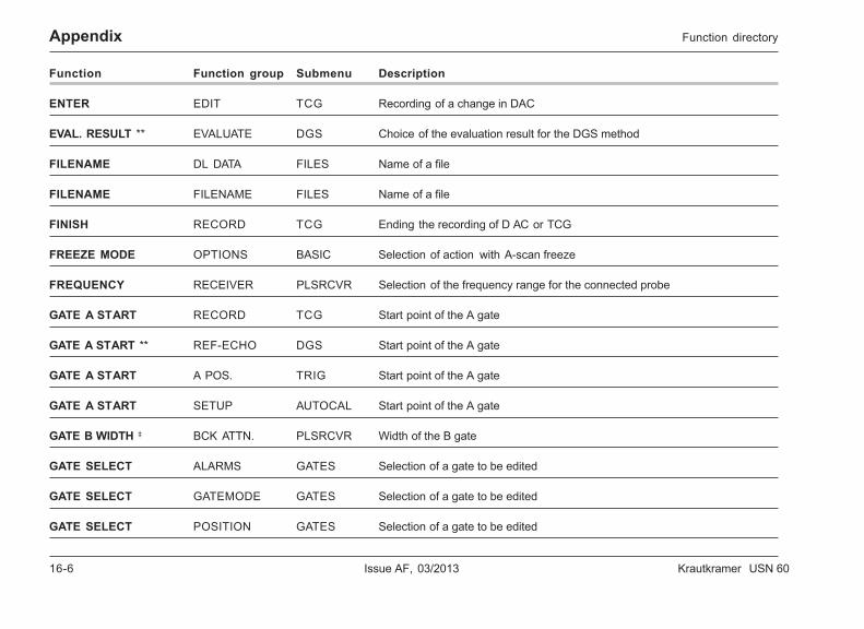
16-6 Issue AF, 03/2013 Krautkramer USN 60
Appendix Function directory
Function Function group Submenu Description
ENTER EDIT TCG Recording of a change in DAC
EVAL. RESULT ** EVALUATE DGS Choice of the evaluation result for the DGS method
FILENAME DL DATA FILES Name of a file
FILENAME FILENAME FILES Name of a file
FINISH RECORD TCG Ending the recording of D AC or TCG
FREEZE MODE OPTIONS BASIC Selection of action with A-scan freeze
FREQUENCY RECEIVER PLSRCVR Selection of the frequency range for the connected probe
GATE A START RECORD TCG Start point of the A gate
GATE A START ** REF-ECHO DGS Start point of the A gate
GATE A START A POS. TRIG Start point of the A gate
GATE A START SETUP AUTOCAL Start point of the A gate
GATE B WIDTH ‡ BCK ATTN. PLSRCVR Width of the B gate
GATE SELECT ALARMS GATES Selection of a gate to be edited
GATE SELECT GATEMODE GATES Selection of a gate to be edited
GATE SELECT POSITION GATES Selection of a gate to be edited
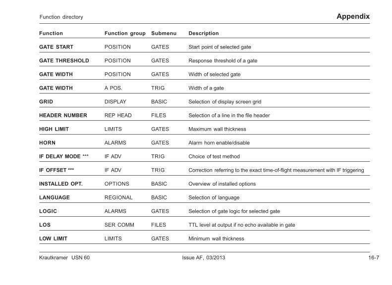
Krautkramer USN 60 Issue AF, 03/2013 16-7
AppendixFunction directory
Function Function group Submenu Description
GATE START POSITION GATES Start point of selected gate
GATE THRESHOLD POSITION GATES Response threshold of a gate
GATE WIDTH POSITION GATES Width of selected gate
GATE WIDTH A POS. TRIG Width of a gate
GRID DISPLAY BASIC Selection of display screen grid
HEADER NUMBER REP HEAD FILES Selection of a line in the file header
HIGH LIMIT LIMITS GATES Maximum wall thickness
HORN ALARMS GATES Alarm horn enable/disable
IF DELAY MODE *** IF ADV TRIG Choice of test method
IF OFFSET *** IF ADV TRIG Correction referring to the exact time-of-flight measurement with IF triggering
INSTALLED OPT. OPTIONS BASIC Overview of installed options
LANGUAGE REGIONAL BASIC Selection of language
LOGIC ALARMS GATES Selection of gate logic for selected gate
LOS SER COMM FILES TTL level at output if no echo available in gate
LOW LIMIT LIMITS GATES Minimum wall thickness
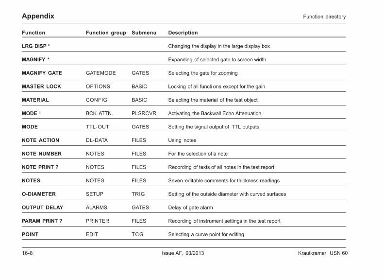
16-8 Issue AF, 03/2013 Krautkramer USN 60
Appendix Function directory
Function Function group Submenu Description
LRG DISP * Changing the display in the large display box
MAGNIFY * Expanding of selected gate to screen width
MAGNIFY GATE GATEMODE GATES Selecting the gate for zooming
MASTER LOCK OPTIONS BASIC Locking of all functi ons except for the gain
MATERIAL CONFIG BASIC Selecting the material of the test object
MODE ‡ BCK ATTN. PLSRCVR Activating the Backwall Echo Attenuation
MODE TTL-OUT GATES Setting the signal output of TTL outputs
NOTE ACTION DL-DATA FILES Using notes
NOTE NUMBER NOTES FILES For the selection of a note
NOTE PRINT ? NOTES FILES Recording of texts of all notes in the test report
NOTES NOTES FILES Seven editable comments for thickness readings
O-DIAMETER SETUP TRIG Setting of the outside diameter with curved surfaces
OUTPUT DELAY ALARMS GATES Delay of gate alarm
PARAM PRINT ? PRINTER FILES Recording of instrument settings in the test report
POINT EDIT TCG Selecting a curve point for editing
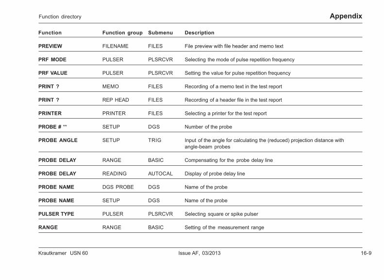
Krautkramer USN 60 Issue AF, 03/2013 16-9
AppendixFunction directory
Function Function group Submenu Description
PREVIEW FILENAME FILES File preview with file header and memo text
PRF MODE PULSER PLSRCVR Selecting the mode of pulse repetition frequency
PRF VALUE PULSER PLSRCVR Setting the value for pulse repetition frequency
PRINT ? MEMO FILES Recording of a memo text in the test report
PRINT ? REP HEAD FILES Recording of a header file in the test report
PRINTER PRINTER FILES Selecting a printer for the test report
PROBE # ** SETUP DGS Number of the probe
PROBE ANGLE SETUP TRIG Input of the angle for calculating the (reduced) projection distance withangle-beam probes
PROBE DELAY RANGE BASIC Compensating for the probe delay line
PROBE DELAY READING AUTOCAL Display of probe delay line
PROBE NAME DGS PROBE DGS Name of the probe
PROBE NAME SETUP DGS Name of the probe
PULSER TYPE PULSER PLSRCVR Selecting square or spike pulser
RANGE RANGE BASIC Setting of the measurement range
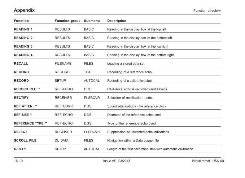
16-10 Issue AF, 03/2013 Krautkramer USN 60
Appendix
Function Function group Submenu Description
READING 1 RESULTS BASIC Reading in the display box at the top left
READING 2 RESULTS BASIC Reading in the display box at the bottom left
READING 3 RESULTS BASIC Reading in the display box at the top right
READING 4 RESULTS BASIC Reading in the display box at the bottom right
RECALL FILENAME FILES Loading a stored data set
RECORD RECORD TCG Recording of a reference echo
RECORD SETUP AUTOCAL Recording of a calibration step
RECORD REF ** REF-ECHO DGS Reference echo is recorded (and saved)
RECTIFY RECEIVER PLSRCVR Selection of rectification mode
REF ATTEN. ** REF CORR DGS Sound attenuation in the reference block
REF SIZE ** REF-ECHO DGS Diameter of the reference echo used
REFERENCE TYPE ** REF-ECHO DGS Type of the ref erence echo used
REJECT RECEIVER PLSRCVR Suppression of unwanted echo indications
SCROLL FILE DL DATA FILES Navigation within a Data Logger file
S-REF1 SETUP AUTOCAL Length of the first calibration step with automatic calibration
Function directory
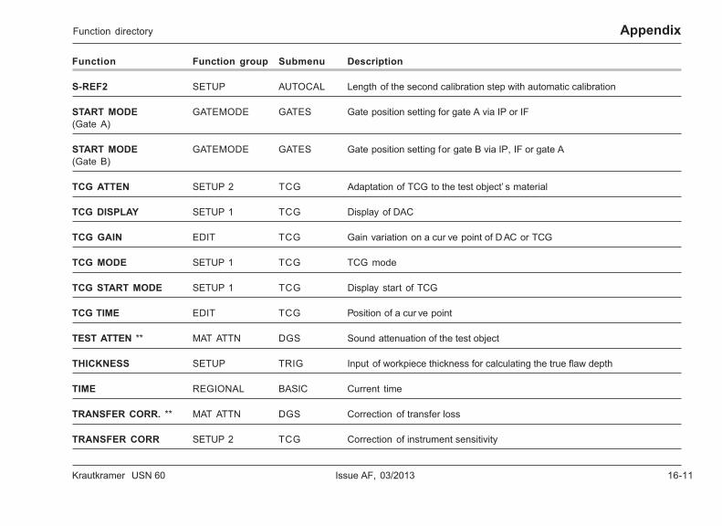
Krautkramer USN 60 Issue AF, 03/2013 16-11
Appendix
Function Function group Submenu Description
S-REF2 SETUP AUTOCAL Length of the second calibration step with automatic calibration
START MODE GATEMODE GATES Gate position setting for gate A via IP or IF(Gate A)
START MODE GATEMODE GATES Gate position setting for gate B via IP, IF or gate A(Gate B)
TCG ATTEN SETUP 2 TCG Adaptation of TCG to the test object’ s material
TCG DISPLAY SETUP 1 TCG Display of DAC
TCG GAIN EDIT TCG Gain variation on a cur ve point of D AC or TCG
TCG MODE SETUP 1 TCG TCG mode
TCG START MODE SETUP 1 TCG Display start of TCG
TCG TIME EDIT TCG Position of a cur ve point
TEST ATTEN ** MAT ATTN DGS Sound attenuation of the test object
THICKNESS SETUP TRIG Input of workpiece thickness for calculating the true flaw depth
TIME REGIONAL BASIC Current time
TRANSFER CORR. ** MAT ATTN DGS Correction of transfer loss
TRANSFER CORR SETUP 2 TCG Correction of instrument sensitivity
Function directory
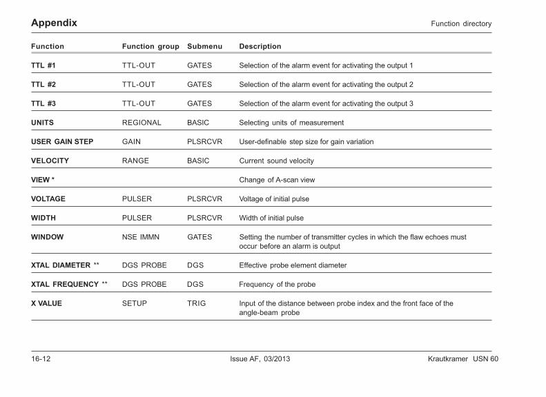
16-12 Issue AF, 03/2013 Krautkramer USN 60
Appendix
Function Function group Submenu Description
TTL #1 TTL-OUT GATES Selection of the alarm event for activating the output 1
TTL #2 TTL-OUT GATES Selection of the alarm event for activating the output 2
TTL #3 TTL-OUT GATES Selection of the alarm event for activating the output 3
UNITS REGIONAL BASIC Selecting units of measurement
USER GAIN STEP GAIN PLSRCVR User-definable step size for gain variation
VELOCITY RANGE BASIC Current sound velocity
VIEW * Change of A-scan view
VOLTAGE PULSER PLSRCVR Voltage of initial pulse
WIDTH PULSER PLSRCVR Width of initial pulse
WINDOW NSE IMMN GATES Setting the number of transmitter cycles in which the flaw echoes mustoccur before an alarm is output
XTAL DIAMETER ** DGS PROBE DGS Effective probe element diameter
XTAL FREQUENCY ** DGS PROBE DGS Frequency of the probe
X VALUE SETUP TRIG Input of the distance between probe index and the front face of theangle-beam probe
Function directory
Krautkramer USN 60 Issue AF, 03/2013 16-13
Appendix
EU declaration of conformity
16-14 Issue AF, 03/2013 Krautkramer USN 60
Appendix
16.2 Manufacturer/Service addresses
The Krautkramer USN 60 is manufactured by:
GE Inspection Technologies, LP50 Industrial Park RoadUSA – Lewistown, PA 17044
Phone +1 717 - 242 03 27Fax +1 717 - 242 26 06
The Krautkramer USN 60 is manufactured using high-quality components according to state-of-the-art meth-ods. Thorough in process inspections and a quality man-agement system certified according to DIN EN ISO 9001ensure an optimum quality of conformance of the in-strument.
Should you nevertheless detect an error or malfunctionon your product, please inform the Service of GE In-spection Technologies responsible for your products bygiving the details (if possible, error number) and a de-scription of the error or malfunction.
Keep the shipping container for any possibly requiredrepair work that cannot be carried out on site.
If there’s anything specific you would like to know aboutthe use, handling, operation and specifications of yourinstrument, or about our Service Agreement, pleasecontact your local representative of GE InspectionTechnologies, or one of the following direct addresses:
GE Inspection Technologies GmbH
Service-CenterRobert-Bosch-Str. 3D – 50354 Hürth
or:
Postfach 1363D – 50330 Hürth
Phone +49 (0) 22 33 - 601 111Fax +49 (0) 22 33 - 601 402
France
GE Inspection Technologies ScsSAC Sans Souci68, Chemin des OrmeauxF – 69760 Limonest
Phone +33 4 72 - 17 92 20Fax +33 4 78 - 47 56 98
Manufacturer/Service addresses
Krautkramer USN 60 Issue AF, 03/2013 16-15
AppendixManufacturer/Service addresses
Great Britain
GE Inspection Technologies892 Charter AvenueCanleyGB – Coventry CV4 8AF
Phone +44 845 - 130 - 3925Fax +44 845 - 130 - 5775
USA
GE Inspection Technologies, LP50 Industrial Park RoadP.O. Box 350USA – Lewistown, PA 17044
Phone +1 717 - 242 03 27Fax +1 717 - 242 26 06

16-16 Issue AF, 03/2013 Krautkramer USN 60
Krautkramer USN 60 Issue AF, 03/2013 17-1
Changes 17
17-2 Issue AF, 03/2013 Krautkramer USN 60
Changes
This chapter contains information about changes andadditions made at short notice and not yet included inthe operating manual.
If none exist, the chapter remains blank.
Krautkramer USN 60 Issue AF, 03/2013 18-1
Index 18
18-2 Issue AF, 03/2013 Krautkramer USN 60
Index
AA POS. . . . . . . . . . . . . . . . . . . . . . . . . . . . . . . . . 5 -43
A THRESHOLD . . . . . . . . . . . . . . . . . . . . . . 5 -44, 9 -4
A-scan display . . . . . . . . . . . . . . . . . . . . . . . . 4 -4, 5 -7
A-scan display delay . . . . . . . . . . . . . . . . . . . . . . . 5 -5
A-scan freeze . . . . . . . . . . . . . . . . . . . . . . . . . . . 5 -13
Accessories recommended . . . . . . . . . . . . . . . . . . 2 -4
ACTION . . . . . . . . . . . . . . . . . . . . . . . . . . . . . . . . 5 -50
Additions . . . . . . . . . . . . . . . . . . . . . . . . . . . . . . . 17 -2
Addresses . . . . . . . . . . . . . . . . . . . . . . . 16 -14, 16 -15
Alarm . . . . . . . . . . . . . . . . . . . . . . . . . . . . . . . . . . 5 -33
Alarm output . . . . . . . . . . . . . . . . . . . . . . . . . . . . 5 -34
ALARM RST . . . . . . . . . . . . . . . . . . . . . . . . . . . . . 6 -5
ALARM SELECT . . . . . . . . . . . . . . . . . . . . . . . . . 5 -38
Alarm signal . . . . . . . . . . . . . . . . . . . . . . . . . . . . 5 -35
ALARMS . . . . . . . . . . . . . . . . . . . . . . . . . . . . . . . 5 -33
Alkaline batteries . . . . . . . . . . . . . . . . . . . . . . . . . 14 -4
AMPL CORRECT . . . . . . . . . . . . . . . . . . . . . . . . 10-15
AMPLITUDE . . . . . . . . . . . . . . . . . . . . . . . . . . . . 5 -25
Analog display . . . . . . . . . . . . . . . . . . . . . . . 5 -8, 7 -15
Analog outputs . . . . . . . . . . . . . . . . . . . . . . . . . 15 -22
Angle of incidence . . . . . . . . . . . . . . . . . . . . . . . . 5 -40
Angle-beam probe . . . . . . . . . . . . . . . . . . . . 5 -39, 7 -6
ASCAN COLOR . . . . . . . . . . . . . . . . . . . . . . . . . . 5 -9
ASCAN ENHANCE . . . . . . . . . . . . . . . . . . . . . . . . 5 -8
ASCAN MODE . . . . . . . . . . . . . . . . . . . . . . . . . . . 5 -7
ASCAN PRINT? . . . . . . . . . . . . . . . . . . . . . . . . . 5 -57
AUTOCAL submenu . . . . . . . . . . . . . . . . . . . . . . 5 -46
Automatic calibration . . . . . . . . . . . . . . . . . . 5 -46, 7 -9
AWS MODE . . . . . . . . . . . . . . . . . . . . . . . . . . . . 5 -44
Krautkramer USN 60 Issue AF, 03/2013 18-3
Index
BB START . . . . . . . . . . . . . . . . . . . . . . . . . . . . . . . 12 -5
BASIC submenu . . . . . . . . . . . . . . . . . . . . . . . . . . 5 -3
Batteries . . . . . . . . . . . . . . . . . . . . . . . . . . . . . . . . 1 -2Care . . . . . . . . . . . . . . . . . . . . . . . . . . . . . . . . . 14 -3Charging . . . . . . . . . . . . . . . . . . . . . . . . . . . . . . . 3 -6Inserting . . . . . . . . . . . . . . . . . . . . . . . . . . . . . . . 3 -4Installing . . . . . . . . . . . . . . . . . . . . . . . . . . . . . . 3 -4Maintaining . . . . . . . . . . . . . . . . . . . . . . . . . . . 14 -2
BATTERY TYPE . . . . . . . . . . . . . . . . . . . . . . . . . 5 -14
Battery type . . . . . . . . . . . . . . . . . . . . . . . . . . . . . . 3 -5
BAUD RATE . . . . . . . . . . . . . . . . . . . . . . . . . . . . 5 -58
BCK ATTN . . . . . . . . . . . . . . . . . . . . . . . . . . . . . . 12 -3
BRIGHTNESS . . . . . . . . . . . . . . . . . . . . . . . . . . . 5 -10
Brightness . . . . . . . . . . . . . . . . . . . . . . . . . . . . . . 4 -19
BW . . . . . . . . . . . . . . . . . . . . . . . . . . . . . . . . . . . 10-11
BW GAIN. . . . . . . . . . . . . . . . . . . . . . . . . . . . . . . 12 -4
CCalibrating . . . . . . . . . . . . . . . . . . . . . . . . . . . . . . . 7 -3
Calibrating the sensitivity . . . . . . . . . . . . . . . . . . 7 -11
Care . . . . . . . . . . . . . . . . . . . . . . . . . . . . . . . . . . . 14 -2
Changes . . . . . . . . . . . . . . . . . . . . . . . . . . . . . . . 17 -1
CLEAR READING . . . . . . . . . . . . . . . . . . . . . . . . 5 -60
Coarse and fine setting . . . . . . . . . . . . . . . . . . . . 4 -11
Codes for remote control . . . . . . . . . . . . . . . . . . 15 -10
Cold start . . . . . . . . . . . . . . . . . . . . . . . . . . . . . . . . 3 -8
COLOR LEG . . . . . . . . . . . . . . . . . . . . . . . . . . . . 5 -45
COLOR SCHEME . . . . . . . . . . . . . . . . . . . . . . . . . 5 -9
Color scheme . . . . . . . . . . . . . . . . . . . . . . . 4 -17, 5 -9
COLORING . . . . . . . . . . . . . . . . . . . . . . . . . . . . . 5 -44
CONFIG . . . . . . . . . . . . . . . . . . . . . . . . . . . . . . . . 5 -6
Connecting a probe . . . . . . . . . . . . . . . . . . . . . . . . 3 -7
Control elements . . . . . . . . . . . . . . . . . . . . . . . . . . 4 -2
COPY key . . . . . . . . . . . . . . . . . . . . . . . . . . . . . . 13 -3
COPY MODE . . . . . . . . . . . . . . . . . . . . . . . . . . . 5 -57
Corrections . . . . . . . . . . . . . . . . . . . . . . . . . . . . . . 11-9

18-4 Issue AF, 03/2013 Krautkramer USN 60
Index
COUNT . . . . . . . . . . . . . . . . . . . . . . . . . . . . . . . . 5 -38
CREATE NEW . . . . . . . . . . . . . . . . . . . . . . . . . . . 5 -51
Creating file header . . . . . . . . . . . . . . . . . . . . . . . 8 -13
Creating memo texts . . . . . . . . . . . . . . . . . . . . . . 8 -14
Custom Linear file . . . . . . . . . . . . . . . . . . . . . . . . . 8 -8
DDAC mode . . . . . . . . . . . . . . . . . . . . . . . . . . . . . . 9 -15
DAC OFFSET . . . . . . . . . . . . . . . . . . . . . . . . . . . . 9 -8
DAC recording . . . . . . . . . . . . . . . . . . . . . . . . . . . 9 -10
DAMPING . . . . . . . . . . . . . . . . . . . . . . . . . . . . . . 5 -21
Data communication . . . . . . . . . . . . . . . . . . . . . . 15 -5
Data Logger . . . . . . . . . . . . . . . . . . . . . . . . . . . . . . 8 -4
Data sets . . . . . . . . . . . . . . . . . . . . . . . . . . . . . . . . 8 -3
Data transfer . . . . . . . . . . . . . . . . . . . . . . . . . . . . 15 -6
Data transfer formats . . . . . . . . . . . . . . . . . . . . . . 15 -6
Data transmission . . . . . . . . . . . . . . . . . . . . . . . . 15 -2
Data transmission rate . . . . . . . . . . . . . . . . . . . . 5 -58
DATE . . . . . . . . . . . . . . . . . . . . . . . . . . . . . . . . . . 5 -11
Date . . . . . . . . . . . . . . . . . . . . . . . . . . . . . . . . . . . 4 -16
db REF . . . . . . . . . . . . . . . . . . . . . . . . . . . . 5 -25, 6 -3
dB STEP . . . . . . . . . . . . . . . . . . . . . . . . . . . 5 -26, 6 -3
DB TO CURVE . . . . . . . . . . . . . . . . . . . . . . . . . . . . 10-9
Defects . . . . . . . . . . . . . . . . . . . . . . . . . . . . . . . . . 1 -3
DELAY VELOCITY . . . . . . . . . . . . . . . . . . . 10-8, 11-4
DELETE CURVE ! . . . . . . . . . . . . . . . . . . . . . . . . . 9 -6
DELETE REF . . . . . . . . . . . . . . . . . . . . . . . . . . . 10-15
Deleting saved files . . . . . . . . . . . . . . . . . . . . . . . 8 -16
Depth position . . . . . . . . . . . . . . . . . . . . . . . . . . . 5 -39
DETECTION . . . . . . . . . . . . . . . . . . . . . . . . . . . . 5 -31
DGS CURVE . . . . . . . . . . . . . . . . . . . . . . . 10-5, 10-10
DGS flaw evaluation . . . . . . . . . . . . . . . . . . . . . . 10-21
DGS MODE . . . . . . . . . . . . . . . . . . . . . . . . . . . . . . 10-5
DGS PROBE function group . . . . . . . . . . . . . . . . . 10-7
DGS submenu . . . . . . . . . . . . . . . . . . . . . . . . . . . . 10-4
Krautkramer USN 60 Issue AF, 03/2013 18-5
Index
Directives . . . . . . . . . . . . . . . . . . . . . . . . . . . . . 16 -13
DISPLAY . . . . . . . . . . . . . . . . . . . . . . . . . . . . . . . . 5 -8
Display . . . . . . . . . . . . . . . . . . . . . . . . . . . . . . . . . 4 -4
Display boxes for readings . . . . . . . . . . . . . . . . . . 4 -6
DISPLAY DELAY. . . . . . . . . . . . . . . . . . . . . . . . . . 5 -5
Display range calibration . . . . . . . . . . . . . . . . . . . . 7 -3
DISPLAY START . . . . . . . . . . . . . . . . . . . . . . . . . . 5 -7
Display view . . . . . . . . . . . . . . . . . . . . . . . . . . . . . 6 -4
Display zero . . . . . . . . . . . . . . . . . . . . . . . . . . . . . 11-6
Distance . . . . . . . . . . . . . . . . . . . . . . . . . . . . . . . . 10-2
DL DATA . . . . . . . . . . . . . . . . . . . . . . . . . . . . . . . 5 -59
DL PRINT ? . . . . . . . . . . . . . . . . . . . . . . . . . . . . . 5 -54
DUAL . . . . . . . . . . . . . . . . . . . . . . . . . . . . . . . . . . 5 -23
Dual mode . . . . . . . . . . . . . . . . . . . . . . . . . . . . . . 5 -23
Dual-element probe . . . . . . . . . . . . . . . . . . . . . . . . 7 -8
EEcho display comparison method . . . . . . . . . . . . . 1 -7
Echo evaluation . . . . . . . . . . . . . . . . . . . . . . . . . . 9 -14
EDIT . . . . . . . . . . . . . . . . . . . 5 -52, 5 -54, 5 -55, 9 -9
Editing saved files . . . . . . . . . . . . . . . . . . . . . . . . 8 -16
Editor menu . . . . . . . . . . . . . . . . . . . . . . . . . . . . . 4 -12
EFF. DIAMETER . . . . . . . . . . . . . . . . . . . . . . . . . . 10-8
Enabling the AWS . . . . . . . . . . . . . . . . . . . . . . . . 5 -44
ENERGY . . . . . . . . . . . . . . . . . . . . . . . . . . . . . . . 5 -21
ENTER . . . . . . . . . . . . . . . . . . . . . . . . . . . . . . . . 9 -10
Errors . . . . . . . . . . . . . . . . . . . . . . . . . . . . . . . . . . . 1 -3
ERS . . . . . . . . . . . . . . . . . . . . . . . . . . . . . . . . . . . . 10-9
EVAL. RESULT . . . . . . . . . . . . . . . . . . . . . . . . . . . 10-9
EVALUATE function group . . . . . . . . . . . . . . . . . . . 10-9
Exhausted batteries . . . . . . . . . . . . . . . . . . . . . . 14 -3
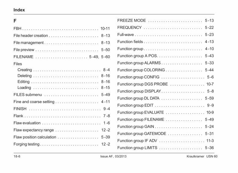
18-6 Issue AF, 03/2013 Krautkramer USN 60
Index
FFBH . . . . . . . . . . . . . . . . . . . . . . . . . . . . . . . . . . . 10-11
File header creation . . . . . . . . . . . . . . . . . . . . . . . 8 -13
File management . . . . . . . . . . . . . . . . . . . . . . . . . 8 -13
File preview . . . . . . . . . . . . . . . . . . . . . . . . . . . . . 5 -50
FILENAME . . . . . . . . . . . . . . . . . . . . . . . . 5 -49, 5 -60
FilesCreating . . . . . . . . . . . . . . . . . . . . . . . . . . . . . . . 8 -4Deleting . . . . . . . . . . . . . . . . . . . . . . . . . . . . . . 8 -16Editing . . . . . . . . . . . . . . . . . . . . . . . . . . . . . . . 8 -16Loading . . . . . . . . . . . . . . . . . . . . . . . . . . . . . . 8 -15
FILES submenu . . . . . . . . . . . . . . . . . . . . . . . . . 5 -49
Fine and coarse setting . . . . . . . . . . . . . . . . . . . . 4 -11
FINISH . . . . . . . . . . . . . . . . . . . . . . . . . . . . . . . . . 9 -4
Flank . . . . . . . . . . . . . . . . . . . . . . . . . . . . . . . . . . . 7 -8
Flaw evaluation . . . . . . . . . . . . . . . . . . . . . . . . . . . 1 -6
Flaw expectancy range . . . . . . . . . . . . . . . . . . . . 12 -2
Flaw position calculation . . . . . . . . . . . . . . . . . . . 5 -39
Forging testing . . . . . . . . . . . . . . . . . . . . . . . . . . . 12 -2
FREEZE MODE . . . . . . . . . . . . . . . . . . . . . . . . . 5 -13
FREQUENCY . . . . . . . . . . . . . . . . . . . . . . . . . . . 5 -22
Full-wave . . . . . . . . . . . . . . . . . . . . . . . . . . . . . . . 5 -23
Function fields . . . . . . . . . . . . . . . . . . . . . . . . . . . 4 -13
Function group . . . . . . . . . . . . . . . . . . . . . . . . . . . 4 -10
Function group A POS. . . . . . . . . . . . . . . . . . . . . 5 -43
Function group ALARMS . . . . . . . . . . . . . . . . . . . 5 -33
Function group COLORING . . . . . . . . . . . . . . . . . 5 -44
Function group CONFIG . . . . . . . . . . . . . . . . . . . . 5 -6
Function group DGS PROBE . . . . . . . . . . . . . . . . 10-7
Function group DISPLAY. . . . . . . . . . . . . . . . . . . . 5 -8
Function group DL DATA . . . . . . . . . . . . . . . . . . . 5 -59
Function group EDIT . . . . . . . . . . . . . . . . . . . . . . . 9 -9
Function group EVALUATE . . . . . . . . . . . . . . . . . . 10-9
Function group FILENAME . . . . . . . . . . . . . . . . . 5 -49
Function group GAIN . . . . . . . . . . . . . . . . . . . . . . 5 -24
Function group GATEMODE . . . . . . . . . . . . . . . . 5 -31
Function group IF ADV . . . . . . . . . . . . . . . . . . . . . 11-3
Function group LIMITS . . . . . . . . . . . . . . . . . . . . 5 -36
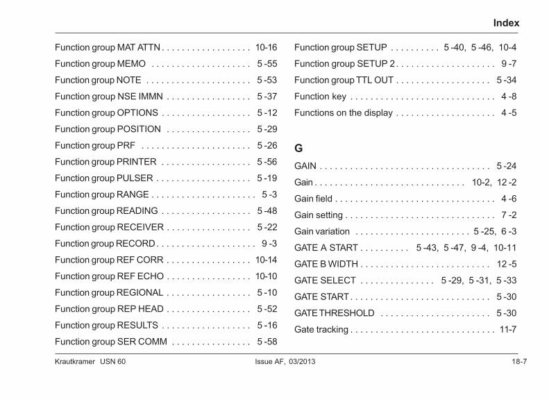
Krautkramer USN 60 Issue AF, 03/2013 18-7
Index
Function group MAT ATTN . . . . . . . . . . . . . . . . . . 10-16
Function group MEMO . . . . . . . . . . . . . . . . . . . . 5 -55
Function group NOTE . . . . . . . . . . . . . . . . . . . . . 5 -53
Function group NSE IMMN . . . . . . . . . . . . . . . . . 5 -37
Function group OPTIONS . . . . . . . . . . . . . . . . . . 5 -12
Function group POSITION . . . . . . . . . . . . . . . . . 5 -29
Function group PRF . . . . . . . . . . . . . . . . . . . . . . 5 -26
Function group PRINTER . . . . . . . . . . . . . . . . . . 5 -56
Function group PULSER . . . . . . . . . . . . . . . . . . . 5 -19
Function group RANGE . . . . . . . . . . . . . . . . . . . . . 5 -3
Function group READING . . . . . . . . . . . . . . . . . . 5 -48
Function group RECEIVER . . . . . . . . . . . . . . . . . 5 -22
Function group RECORD. . . . . . . . . . . . . . . . . . . . 9 -3
Function group REF CORR . . . . . . . . . . . . . . . . . 10-14
Function group REF ECHO . . . . . . . . . . . . . . . . . 10-10
Function group REGIONAL . . . . . . . . . . . . . . . . . 5 -10
Function group REP HEAD . . . . . . . . . . . . . . . . . 5 -52
Function group RESULTS . . . . . . . . . . . . . . . . . . 5 -16
Function group SER COMM . . . . . . . . . . . . . . . . 5 -58
Function group SETUP . . . . . . . . . . 5 -40, 5 -46, 10-4
Function group SETUP 2 . . . . . . . . . . . . . . . . . . . . 9 -7
Function group TTL OUT . . . . . . . . . . . . . . . . . . . 5 -34
Function key . . . . . . . . . . . . . . . . . . . . . . . . . . . . . 4 -8
Functions on the display . . . . . . . . . . . . . . . . . . . . 4 -5
GGAIN . . . . . . . . . . . . . . . . . . . . . . . . . . . . . . . . . . 5 -24
Gain . . . . . . . . . . . . . . . . . . . . . . . . . . . . . . 10-2, 12 -2
Gain field . . . . . . . . . . . . . . . . . . . . . . . . . . . . . . . . 4 -6
Gain setting . . . . . . . . . . . . . . . . . . . . . . . . . . . . . . 7 -2
Gain variation . . . . . . . . . . . . . . . . . . . . . . . 5 -25, 6 -3
GATE A START . . . . . . . . . . 5 -43, 5 -47, 9 -4, 10-11
GATE B WIDTH . . . . . . . . . . . . . . . . . . . . . . . . . . 12 -5
GATE SELECT . . . . . . . . . . . . . . . 5 -29, 5 -31, 5 -33
GATE START. . . . . . . . . . . . . . . . . . . . . . . . . . . . 5 -30
GATE THRESHOLD . . . . . . . . . . . . . . . . . . . . . . 5 -30
Gate tracking . . . . . . . . . . . . . . . . . . . . . . . . . . . . . 11-7
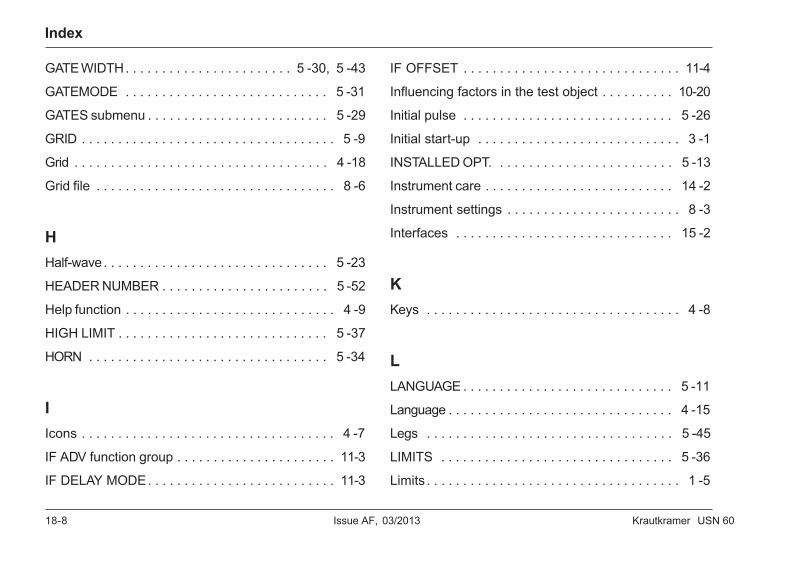
18-8 Issue AF, 03/2013 Krautkramer USN 60
Index
GATE WIDTH. . . . . . . . . . . . . . . . . . . . . . . 5 -30, 5 -43
GATEMODE . . . . . . . . . . . . . . . . . . . . . . . . . . . . 5 -31
GATES submenu . . . . . . . . . . . . . . . . . . . . . . . . . 5 -29
GRID . . . . . . . . . . . . . . . . . . . . . . . . . . . . . . . . . . . 5 -9
Grid . . . . . . . . . . . . . . . . . . . . . . . . . . . . . . . . . . . 4 -18
Grid file . . . . . . . . . . . . . . . . . . . . . . . . . . . . . . . . . 8 -6
HHalf-wave . . . . . . . . . . . . . . . . . . . . . . . . . . . . . . . 5 -23
HEADER NUMBER . . . . . . . . . . . . . . . . . . . . . . . 5 -52
Help function . . . . . . . . . . . . . . . . . . . . . . . . . . . . . 4 -9
HIGH LIMIT . . . . . . . . . . . . . . . . . . . . . . . . . . . . . 5 -37
HORN . . . . . . . . . . . . . . . . . . . . . . . . . . . . . . . . . 5 -34
IIcons . . . . . . . . . . . . . . . . . . . . . . . . . . . . . . . . . . . 4 -7
IF ADV function group . . . . . . . . . . . . . . . . . . . . . . 11-3
IF DELAY MODE. . . . . . . . . . . . . . . . . . . . . . . . . . 11-3
IF OFFSET . . . . . . . . . . . . . . . . . . . . . . . . . . . . . . 11-4
Influencing factors in the test object . . . . . . . . . . 10-20
Initial pulse . . . . . . . . . . . . . . . . . . . . . . . . . . . . . 5 -26
Initial start-up . . . . . . . . . . . . . . . . . . . . . . . . . . . . 3 -1
INSTALLED OPT. . . . . . . . . . . . . . . . . . . . . . . . . 5 -13
Instrument care . . . . . . . . . . . . . . . . . . . . . . . . . . 14 -2
Instrument settings . . . . . . . . . . . . . . . . . . . . . . . . 8 -3
Interfaces . . . . . . . . . . . . . . . . . . . . . . . . . . . . . . 15 -2
KKeys . . . . . . . . . . . . . . . . . . . . . . . . . . . . . . . . . . . 4 -8
LLANGUAGE . . . . . . . . . . . . . . . . . . . . . . . . . . . . . 5 -11
Language . . . . . . . . . . . . . . . . . . . . . . . . . . . . . . . 4 -15
Legs . . . . . . . . . . . . . . . . . . . . . . . . . . . . . . . . . . 5 -45
LIMITS . . . . . . . . . . . . . . . . . . . . . . . . . . . . . . . . 5 -36
Limits . . . . . . . . . . . . . . . . . . . . . . . . . . . . . . . . . . . 1 -5
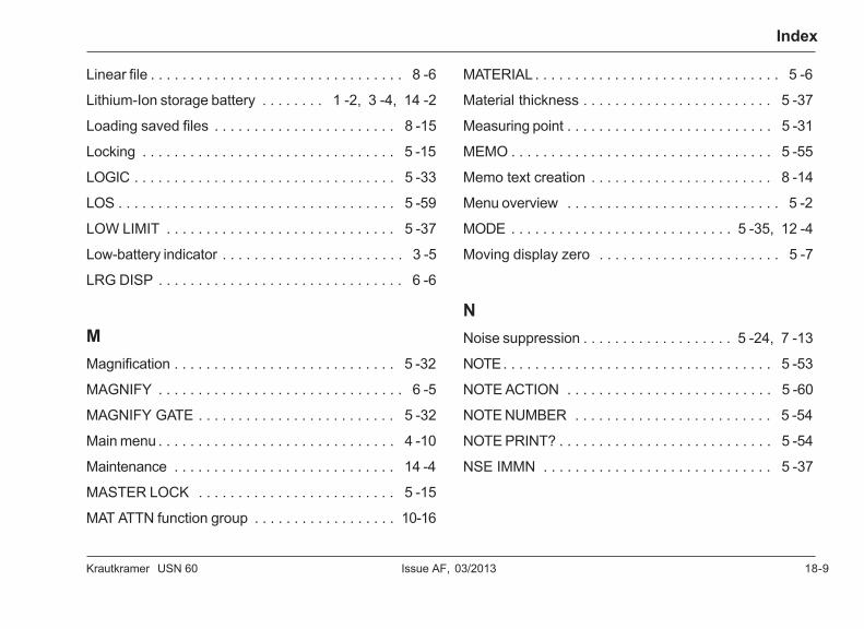
Krautkramer USN 60 Issue AF, 03/2013 18-9
Index
Linear file . . . . . . . . . . . . . . . . . . . . . . . . . . . . . . . . 8 -6
Lithium-Ion storage battery . . . . . . . . 1 -2, 3 -4, 14 -2
Loading saved files . . . . . . . . . . . . . . . . . . . . . . . 8 -15
Locking . . . . . . . . . . . . . . . . . . . . . . . . . . . . . . . . 5 -15
LOGIC . . . . . . . . . . . . . . . . . . . . . . . . . . . . . . . . . 5 -33
LOS . . . . . . . . . . . . . . . . . . . . . . . . . . . . . . . . . . . 5 -59
LOW LIMIT . . . . . . . . . . . . . . . . . . . . . . . . . . . . . 5 -37
Low-battery indicator . . . . . . . . . . . . . . . . . . . . . . . 3 -5
LRG DISP . . . . . . . . . . . . . . . . . . . . . . . . . . . . . . . 6 -6
MMagnification . . . . . . . . . . . . . . . . . . . . . . . . . . . . 5 -32
MAGNIFY . . . . . . . . . . . . . . . . . . . . . . . . . . . . . . . 6 -5
MAGNIFY GATE . . . . . . . . . . . . . . . . . . . . . . . . . 5 -32
Main menu . . . . . . . . . . . . . . . . . . . . . . . . . . . . . . 4 -10
Maintenance . . . . . . . . . . . . . . . . . . . . . . . . . . . . 14 -4
MASTER LOCK . . . . . . . . . . . . . . . . . . . . . . . . . 5 -15
MAT ATTN function group . . . . . . . . . . . . . . . . . . 10-16
MATERIAL . . . . . . . . . . . . . . . . . . . . . . . . . . . . . . . 5 -6
Material thickness . . . . . . . . . . . . . . . . . . . . . . . . 5 -37
Measuring point . . . . . . . . . . . . . . . . . . . . . . . . . . 5 -31
MEMO . . . . . . . . . . . . . . . . . . . . . . . . . . . . . . . . . 5 -55
Memo text creation . . . . . . . . . . . . . . . . . . . . . . . 8 -14
Menu overview . . . . . . . . . . . . . . . . . . . . . . . . . . . 5 -2
MODE . . . . . . . . . . . . . . . . . . . . . . . . . . . . 5 -35, 12 -4
Moving display zero . . . . . . . . . . . . . . . . . . . . . . . 5 -7
NNoise suppression . . . . . . . . . . . . . . . . . . . 5 -24, 7 -13
NOTE. . . . . . . . . . . . . . . . . . . . . . . . . . . . . . . . . . 5 -53
NOTE ACTION . . . . . . . . . . . . . . . . . . . . . . . . . . 5 -60
NOTE NUMBER . . . . . . . . . . . . . . . . . . . . . . . . . 5 -54
NOTE PRINT? . . . . . . . . . . . . . . . . . . . . . . . . . . . 5 -54
NSE IMMN . . . . . . . . . . . . . . . . . . . . . . . . . . . . . 5 -37
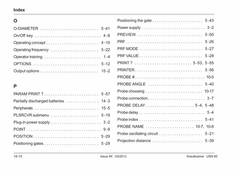
18-10 Issue AF, 03/2013 Krautkramer USN 60
Index
OO-DIAMETER . . . . . . . . . . . . . . . . . . . . . . . . . . . 5 -41
On/Off key . . . . . . . . . . . . . . . . . . . . . . . . . . . . . . . 4 -8
Operating concept . . . . . . . . . . . . . . . . . . . . . . . . 4 -10
Operating frequency . . . . . . . . . . . . . . . . . . . . . . 5 -22
Operator training . . . . . . . . . . . . . . . . . . . . . . . . . . 1 -4
OPTIONS . . . . . . . . . . . . . . . . . . . . . . . . . . . . . . 5 -12
Output options . . . . . . . . . . . . . . . . . . . . . . . . . . . 15 -2
PPARAM PRINT ? . . . . . . . . . . . . . . . . . . . . . . . . . 5 -57
Partially discharged batteries . . . . . . . . . . . . . . . 14 -3
Peripherals . . . . . . . . . . . . . . . . . . . . . . . . . . . . . . 15 -5
PLSRCVR submenu . . . . . . . . . . . . . . . . . . . . . . 5 -19
Plug-in power supply . . . . . . . . . . . . . . . . . . . . . . . 3 -2
POINT . . . . . . . . . . . . . . . . . . . . . . . . . . . . . . . . . . 9 -9
POSITION . . . . . . . . . . . . . . . . . . . . . . . . . . . . . . 5 -29
Positioning gates . . . . . . . . . . . . . . . . . . . . . . . . . 5 -29
Positioning the gate . . . . . . . . . . . . . . . . . . . . . . . 5 -43
Power supply . . . . . . . . . . . . . . . . . . . . . . . . . . . . . 3 -2
PREVIEW . . . . . . . . . . . . . . . . . . . . . . . . . . . . . . 5 -50
PRF . . . . . . . . . . . . . . . . . . . . . . . . . . . . . . . . . . . 5 -26
PRF MODE . . . . . . . . . . . . . . . . . . . . . . . . . . . . . 5 -27
PRF VALUE . . . . . . . . . . . . . . . . . . . . . . . . . . . . . 5 -28
PRINT ? . . . . . . . . . . . . . . . . . . . . . . . . . . 5 -53, 5 -55
PRINTER. . . . . . . . . . . . . . . . . . . . . . . . . . . . . . . 5 -56
PROBE # . . . . . . . . . . . . . . . . . . . . . . . . . . . . . . . . 10-5
PROBE ANGLE . . . . . . . . . . . . . . . . . . . . . . . . . 5 -40
Probe choosing . . . . . . . . . . . . . . . . . . . . . . . . . . 10-17
Probe connection . . . . . . . . . . . . . . . . . . . . . . . . . . 3 -7
PROBE DELAY . . . . . . . . . . . . . . . . . . . . . . 5 -4, 5 -48
Probe delay . . . . . . . . . . . . . . . . . . . . . . . . . . . . . . 5 -4
Probe index . . . . . . . . . . . . . . . . . . . . . . . . . . . . . 5 -41
PROBE NAME . . . . . . . . . . . . . . . . . . . . . . 10-7, 10-8
Probe oscillating circuit . . . . . . . . . . . . . . . . . . . . 5 -21
Projection distance . . . . . . . . . . . . . . . . . . . . . . . 5 -39
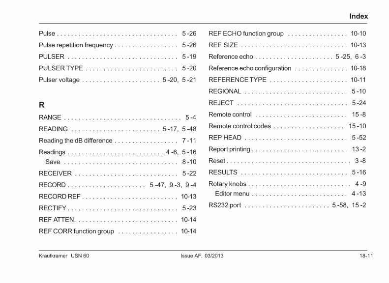
Krautkramer USN 60 Issue AF, 03/2013 18-11
Index
Pulse . . . . . . . . . . . . . . . . . . . . . . . . . . . . . . . . . . 5 -26
Pulse repetition frequency . . . . . . . . . . . . . . . . . . 5 -26
PULSER . . . . . . . . . . . . . . . . . . . . . . . . . . . . . . . 5 -19
PULSER TYPE . . . . . . . . . . . . . . . . . . . . . . . . . . 5 -20
Pulser voltage . . . . . . . . . . . . . . . . . . . . . . 5 -20, 5 -21
RRANGE . . . . . . . . . . . . . . . . . . . . . . . . . . . . . . . . . 5 -4
READING . . . . . . . . . . . . . . . . . . . . . . . . . 5 -17, 5 -48
Reading the dB difference . . . . . . . . . . . . . . . . . . 7 -11
Readings . . . . . . . . . . . . . . . . . . . . . . . . . . . 4 -6, 5 -16Save . . . . . . . . . . . . . . . . . . . . . . . . . . . . . . . . 8 -10
RECEIVER . . . . . . . . . . . . . . . . . . . . . . . . . . . . . 5 -22
RECORD . . . . . . . . . . . . . . . . . . . . . . 5 -47, 9 -3, 9 -4
RECORD REF . . . . . . . . . . . . . . . . . . . . . . . . . . . 10-13
RECTIFY . . . . . . . . . . . . . . . . . . . . . . . . . . . . . . . 5 -23
REF ATTEN. . . . . . . . . . . . . . . . . . . . . . . . . . . . . 10-14
REF CORR function group . . . . . . . . . . . . . . . . . 10-14
REF ECHO function group . . . . . . . . . . . . . . . . . 10-10
REF SIZE . . . . . . . . . . . . . . . . . . . . . . . . . . . . . . 10-13
Reference echo . . . . . . . . . . . . . . . . . . . . . . 5 -25, 6 -3
Reference echo configuration . . . . . . . . . . . . . . . 10-18
REFERENCE TYPE . . . . . . . . . . . . . . . . . . . . . . 10-11
REGIONAL . . . . . . . . . . . . . . . . . . . . . . . . . . . . . 5 -10
REJECT . . . . . . . . . . . . . . . . . . . . . . . . . . . . . . . 5 -24
Remote control . . . . . . . . . . . . . . . . . . . . . . . . . . 15 -8
Remote control codes . . . . . . . . . . . . . . . . . . . . 15 -10
REP HEAD . . . . . . . . . . . . . . . . . . . . . . . . . . . . . 5 -52
Report printing . . . . . . . . . . . . . . . . . . . . . . . . . . . 13 -2
Reset . . . . . . . . . . . . . . . . . . . . . . . . . . . . . . . . . . . 3 -8
RESULTS . . . . . . . . . . . . . . . . . . . . . . . . . . . . . . 5 -16
Rotary knobs . . . . . . . . . . . . . . . . . . . . . . . . . . . . . 4 -9Editor menu . . . . . . . . . . . . . . . . . . . . . . . . . . . 4 -13
RS232 port . . . . . . . . . . . . . . . . . . . . . . . . 5 -58, 15 -2
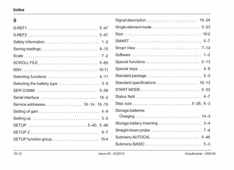
18-12 Issue AF, 03/2013 Krautkramer USN 60
Index
SS-REF1 . . . . . . . . . . . . . . . . . . . . . . . . . . . . . . . . 5 -47
S-REF2 . . . . . . . . . . . . . . . . . . . . . . . . . . . . . . . . 5 -47
Safety information . . . . . . . . . . . . . . . . . . . . . . . . . 1 -2
Saving readings . . . . . . . . . . . . . . . . . . . . . . . . . . 8 -10
Scale . . . . . . . . . . . . . . . . . . . . . . . . . . . . . . . . . . . 7 -2
SCROLL FILE . . . . . . . . . . . . . . . . . . . . . . . . . . . 5 -60
SDH . . . . . . . . . . . . . . . . . . . . . . . . . . . . . . . . . . . 10-11
Selecting functions . . . . . . . . . . . . . . . . . . . . . . . 4 -11
Selecting the battery type . . . . . . . . . . . . . . . . . . . 3 -5
SER COMM . . . . . . . . . . . . . . . . . . . . . . . . . . . . 5 -58
Serial interface . . . . . . . . . . . . . . . . . . . . . . . . . . 15 -2
Service addresses . . . . . . . . . . . . . . . . . 16 -14, 16 -15
Setting of gain . . . . . . . . . . . . . . . . . . . . . . . . . . . . 4 -9
Setting up . . . . . . . . . . . . . . . . . . . . . . . . . . . . . . . 3 -2
SETUP . . . . . . . . . . . . . . . . . . . . . . . . . . . 5 -40, 5 -46
SETUP 2 . . . . . . . . . . . . . . . . . . . . . . . . . . . . . . . . 9 -7
SETUP function group . . . . . . . . . . . . . . . . . . . . . . 10-4
Signal description . . . . . . . . . . . . . . . . . . . . . . . 15 -24
Single-element mode . . . . . . . . . . . . . . . . . . . . . . 5 -23
Size . . . . . . . . . . . . . . . . . . . . . . . . . . . . . . . . . . . . 10-2
SMART . . . . . . . . . . . . . . . . . . . . . . . . . . . . . . . . . 5 -7
Smart View . . . . . . . . . . . . . . . . . . . . . . . . . . . . . 7 -14
Software . . . . . . . . . . . . . . . . . . . . . . . . . . . . . . . . 1 -2
Special functions . . . . . . . . . . . . . . . . . . . . . . . . . 5 -13
Special keys . . . . . . . . . . . . . . . . . . . . . . . . . . . . . 4 -8
Standard package . . . . . . . . . . . . . . . . . . . . . . . . . 2 -3
Standard specifications . . . . . . . . . . . . . . . . . . . 16 -13
START MODE . . . . . . . . . . . . . . . . . . . . . . . . . . . 5 -32
Status field . . . . . . . . . . . . . . . . . . . . . . . . . . . . . . 4 -7
Step size . . . . . . . . . . . . . . . . . . . . . . . . . . . 5 -26, 6 -3
Storage batteriesCharging . . . . . . . . . . . . . . . . . . . . . . . . . . . . . . 14 -3
Storage battery inserting . . . . . . . . . . . . . . . . . . . . 3 -4
Straight-beam probe . . . . . . . . . . . . . . . . . . . . . . . 7 -4
Submenu AUTOCAL . . . . . . . . . . . . . . . . . . . . . . 5 -46
Submenu BASIC . . . . . . . . . . . . . . . . . . . . . . . . . . 5 -3
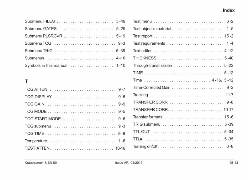
Krautkramer USN 60 Issue AF, 03/2013 18-13
Index
Submenu FILES . . . . . . . . . . . . . . . . . . . . . . . . . 5 -49
Submenu GATES . . . . . . . . . . . . . . . . . . . . . . . . 5 -29
Submenu PLSRCVR . . . . . . . . . . . . . . . . . . . . . . 5 -19
Submenu TCG . . . . . . . . . . . . . . . . . . . . . . . . . . . . 9 -3
Submenu TRIG . . . . . . . . . . . . . . . . . . . . . . . . . . 5 -39
Submenus . . . . . . . . . . . . . . . . . . . . . . . . . . . . . . 4 -10
Symbols in this manual . . . . . . . . . . . . . . . . . . . . 1 -10
TTCG ATTEN . . . . . . . . . . . . . . . . . . . . . . . . . . . . . 9 -7
TCG DISPLAY . . . . . . . . . . . . . . . . . . . . . . . . . . . . 9 -6
TCG GAIN . . . . . . . . . . . . . . . . . . . . . . . . . . . . . . . 9 -9
TCG MODE . . . . . . . . . . . . . . . . . . . . . . . . . . . . . . 9 -5
TCG START MODE . . . . . . . . . . . . . . . . . . . . . . . . 9 -6
TCG submenu . . . . . . . . . . . . . . . . . . . . . . . . . . . . 9 -3
TCG TIME . . . . . . . . . . . . . . . . . . . . . . . . . . . . . . . 9 -9
Temperature . . . . . . . . . . . . . . . . . . . . . . . . . . . . . . 1 -6
TEST ATTEN. . . . . . . . . . . . . . . . . . . . . . . . . . . . 10-16
Test menu . . . . . . . . . . . . . . . . . . . . . . . . . . . . . . . 6 -2
Test object’s material . . . . . . . . . . . . . . . . . . . . . . . 1 -5
Test report . . . . . . . . . . . . . . . . . . . . . . . . . . . . . . 15 -2
Test requirements . . . . . . . . . . . . . . . . . . . . . . . . . 1 -4
Text editor . . . . . . . . . . . . . . . . . . . . . . . . . . . . . . 4 -12
THICKNESS . . . . . . . . . . . . . . . . . . . . . . . . . . . . 5 -40
Through-transmission . . . . . . . . . . . . . . . . . . . . . 5 -23
TIME . . . . . . . . . . . . . . . . . . . . . . . . . . . . . . . . . . 5 -12
Time . . . . . . . . . . . . . . . . . . . . . . . . . . . . . 4 -16, 5 -12
Time-Corrected Gain . . . . . . . . . . . . . . . . . . . . . . . 9 -2
Tracking . . . . . . . . . . . . . . . . . . . . . . . . . . . . . . . . . 11-7
TRANSFER CORR . . . . . . . . . . . . . . . . . . . . . . . . 9 -8
TRANSFER CORR. . . . . . . . . . . . . . . . . . . . . . . . 10-17
Transfer formats . . . . . . . . . . . . . . . . . . . . . . . . . 15 -6
TRIG submenu . . . . . . . . . . . . . . . . . . . . . . . . . . 5 -39
TTL OUT . . . . . . . . . . . . . . . . . . . . . . . . . . . . . . . 5 -34
TTL# . . . . . . . . . . . . . . . . . . . . . . . . . . . . . . . . . . 5 -35
Turning on/off . . . . . . . . . . . . . . . . . . . . . . . . . . . . . 3 -8
18-14 Issue AF, 03/2013 Krautkramer USN 60
Index
UUltrasonic testing . . . . . . . . . . . . . . . . . . . . . . . . . . 1 -3
UNITS . . . . . . . . . . . . . . . . . . . . . . . . . . . . . . . . . 5 -11
Units of measurement . . . . . . . . . . . . . . . . . . . . . 4 -16
USER GAIN STEP . . . . . . . . . . . . . . . . . . . . . . . 5 -25
VV-path error . . . . . . . . . . . . . . . . . . . . . . . . . . . . . . 7 -8
VELOCITY . . . . . . . . . . . . . . . . . . . . . . . . . 5 -5, 5 -48
VGA connection . . . . . . . . . . . . . . . . . . . . . . . . . 15 -4
VIEW . . . . . . . . . . . . . . . . . . . . . . . . . . . . . . . . . . . 6 -4
VOLTAGE . . . . . . . . . . . . . . . . . . . . . . . . . . . . . . 5 -20
WWall thickness . . . . . . . . . . . . . . . . . . . . . . . 1 -6, 5 -40
Wall thickness measurement . . . . . . . . . . . . 1 -5, 7 -12
WIDTH . . . . . . . . . . . . . . . . . . . . . . . . . . . . . . . . . 5 -20
WINDOW . . . . . . . . . . . . . . . . . . . . . . . . . . . . . . . 5 -38
XX VALUE . . . . . . . . . . . . . . . . . . . . . . . . . . . . . . . 5 -41
XTAL FREQUENCY . . . . . . . . . . . . . . . . . . . . . . . 10-8
ZZoom mode . . . . . . . . . . . . . . . . . . . . . . . . . . . . . . 4 -4
Zooming . . . . . . . . . . . . . . . . . . . . . . . . . . . . . . . . 6 -5