Embed Size (px)
Citation preview
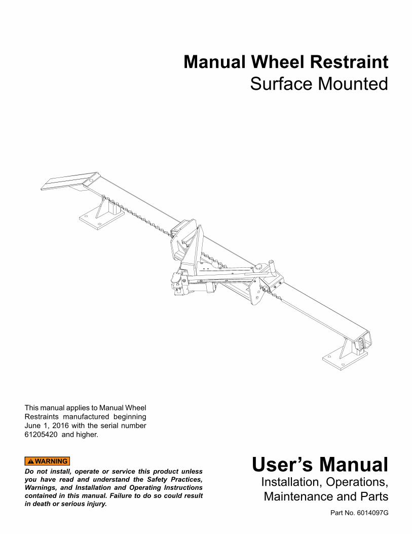
User’s ManualInstallation, Operations,Maintenance and Parts
Part No. 6014097G
Do not install, operate or service this product unless you have read and understand the Safety Practices, Warnings, and Installation and Operating Instructions contained in this manual. Failure to do so could result in death or serious injury.
This manual applies to Manual Wheel Restraints manufactured beginning June 1, 2016 with the serial number 61205420 and higher.
Manual Wheel RestraintSurface Mounted
2 6014097G — Manual Wheel chock August 2016© Entrematic Group AB 2016
INTRODUCTIONWelcome, and thank you for buying this wheel chock from 4Front Engineered Solutions, Inc.
This User’s Manual contains information that you need to safely install, operate and maintain the wheel chock. It also contains a complete parts list and information about ordering replacement parts. Please keep and read this User’s Manual before using your new wheel chock.
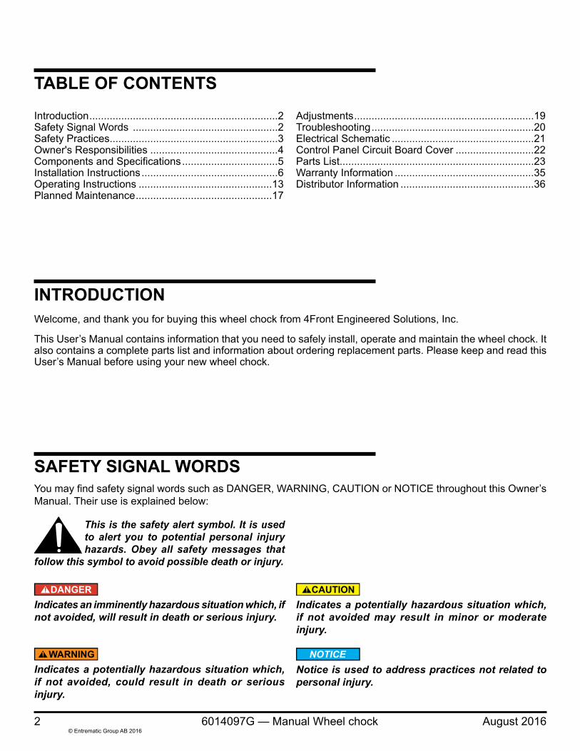
You may find safety signal words such as DANGER, WARNING, CAUTION or NOTICE throughout this Owner’s Manual. Their use is explained below:
Indicates an imminently hazardous situation which, if not avoided, will result in death or serious injury.
Indicates a potentially hazardous situation which, if not avoided, could result in death or serious injury.
Indicates a potentially hazardous situation which, if not avoided may result in minor or moderate injury.
Notice is used to address practices not related to personal injury.
This is the safety alert symbol. It is used to alert you to potential personal injury hazards. Obey all safety messages that
follow this symbol to avoid possible death or injury.
Introduction .................................................................2Safety Signal Words ..................................................2Safety Practices..........................................................3Owner's Responsibilities ............................................4Components and Specifications .................................5Installation Instructions ...............................................6Operating Instructions ..............................................13Planned Maintenance ...............................................17
TABLE OF CONTENTS
SAFETY SIGNAL WORDS
Adjustments ..............................................................19Troubleshooting ........................................................20Electrical Schematic .................................................21Control Panel Circuit Board Cover ...........................22Parts List...................................................................23Warranty Information ................................................35Distributor Information ..............................................36
August 2016 6014097G — Manual Wheel chock 3© Entrematic Group AB 2016
SAFETY PRACTICES
Read these safety practices before installing, operating or servicing the wheel chock. Failure to follow these safety practices could result in death or serious injury.
READ AND FOLLOW THE OPERATING INSTRUCTIONS IN THIS MANUAL BEFORE OPERATING THE WHEEL CHOCK. If you do not understand the instructions, ask your supervisor to teach you how to use the wheel chock.
Improper installation of wheel chock could result in death or serious injury to dock workers or other users of the wheel chock.
Vehicles leaving or moving when loading and unloading are in process could result in death or serious injury.
Be certain bystanders in the driveway stand clear when the wheel chock is operating.
Be certain to follow the installation instructions in this manual.
OPERATIONUse by untrained people can cause property damage, bodily injury and/or death. Your supervisor should teach you the safe and proper way to use the wheel chock. Read and follow the complete OPERATING INSTRUCTIONS starting on page 13 before use. Do not use the wheel chock if it is not working right. Tell your supervisor it needs repair.
Do not operate the wheel chock with equipment, material, or people directly in front of the chock.
Do not use the wheel chock if it looks broken or does not seem to work right. Tell your supervisor at once.
Before chocking vehicle wheel or engaging the wheel chock, dump air from air ride suspensions and set parking brake.
Prior to using the wheel chock:• Ensure the vehicle is parked firmly against the dock
bumpers.
After engaging the wheel chock:• Load or unload the vehicle only when the inside GREEN
light is displayed.
• If the wheel chock cannot make engagement, use wheel chocks to secure the vehicle, then turn selector switch to RESTRAINT OVERRIDE/LIGHTS ONLY.
INSTALLATION, MAINTENANCE AND SERVICEIf the wheel chock does not operate properly using the procedures in this manual, BE CERTAIN TO MANUALLY CHOCK THE VEHICLE WHEELS BEFORE LOADING OR UNLOADING. Call your local distributor for service.
Place barricades around pit on dock floor and drive while installing, maintaining or repairing the wheel chock.
Do not stand in the driveway between the dock and a backing vehicle.
All electrical troubleshooting and repair must be done by a qualified technician and meet all applicable codes.
Before doing any electrical work, make certain the power is disconnected and properly tagged or locked off.
Before doing any welding, make certain the power is disconnected and properly tagged or locked off.
If it is necessary to make troubleshooting checks inside the control box with power on, USE EXTREME CAUTION. Do not place fingers or uninsulated tools inside the control box. Touching wires or other parts inside the control box could result in electrical shock, serious injury or death.
4 6014097G — Manual Wheel chock August 2016© Entrematic Group AB 2016
The owner should recognize the inherent danger of the interface between dock and transport vehicle. The owner should, therefore, train and instruct operators in the safe use of vehicle restraining devices, and take appropriate steps to prevent their use by untrained individuals. The owner shall verify the manual(s) containing the manufacturer's installation, operation, and maintenance requirements, is made available for instruction and training personnel entrusted with such responsibilities.
When industrial vehicles are driven on and off transport vehicles during the loading and unloading operation, the brakes on the transport vehicle shall be applied, and whenever possible, air-ride suspension systems should have the air exhausted and wheel chocks or positive restraints that meet the requirements of ANSI MH30.3 shall be engaged. For more detailed information regarding vehicle restraints see "ANSI MH30.3 Vehicle restraining devices: Performance and Testing" available at www.mhi.org/lodem. When a vehicle restraint is unable to properly engage a transport vehicle, the user shall activate the applicable communication if so included, or provide an alternate method to address a “not restrained vehicle condition” to alert and or protect the loading dock operating personnel.
Manufacturer’s recommended periodic maintenance and inspection procedures in effect at date of shipment shall be followed and written records of the performance of these procedures should be kept. Only trained and authorized personnel shall be permitted to maintain, repair, inspect and adjust the vehicle restraint. Use only original equipment manufacturer parts, manuals, maintenance instructions and labels; or their equivalent.
Restraining devices that are structurally damaged shall be removed from service, inspected by the manufacturer’s representative, and repaired as needed or recommended by the manufacturer before being placed back into service. Modifications or alterations of restraining devices shall be made only with written permission of the original manufacturer. These changes shall be in conformance with all applicable provisions of this standard and shall be at least as safe as the equipment was before modification. These changes shall also satisfy all safety recommendations of the original equipment manufacturer for the particular application of the restraint.
The owner shall see that all nameplates, cautions, instructions, and posted warnings are in place and legible and that these items and communication lights shall not be obscured from the view of operating or maintenance personnel for whom such warnings are intended.
The vehicle restraint shall never be used in a manner not intended by its design. It shall also be compatible with the loading dock equipment and other conditions relating to the loading dock area. When selecting a restraining device, it is important to consider not only present requirements but also future plans or adverse environments.
OWNER’S RESPONSIBILITIES
August 2016 6014097G — Manual Wheel chock 5© Entrematic Group AB 2016
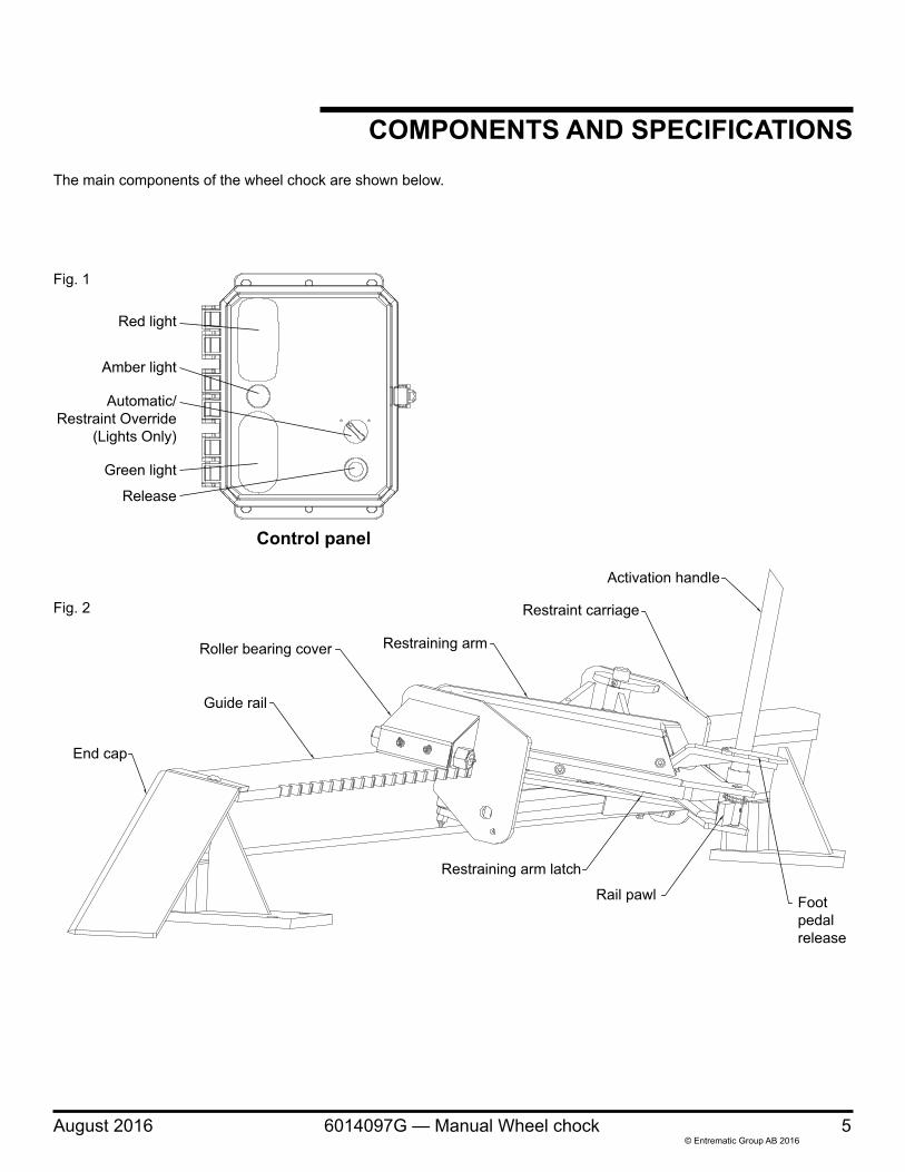
COMPONENTS AND SPECIFICATIONSThe main components of the wheel chock are shown below.
Control panel
Red light
Amber light
Green light
Release
Automatic/Restraint Override
(Lights Only)
Restraining arm
Guide rail
End cap
Restraint carriage
Activation handle
Roller bearing cover
Rail pawl
Restraining arm latch
Footpedalrelease
Fig. 2
Fig. 1
6 6014097G — Manual Wheel chock August 2016© Entrematic Group AB 2016
INSTALLATION INSTRUCTIONS
Before installation read and follow the Safety Practices on page 3. Failure to follow these safety practices could result in death or serious injury.
READ AND FOLLOW THE OPERATION INSTRUCTIONS IN THIS MANUAL BEFORE OPERATING THE WHEEL CHOCK. If you do not understand the instructions, ask your supervisor to teach you how to use the wheel chock.
Improper installation of the wheel chock could result in death or serious injury to dock workers or other users of the wheel chock.
Place barricades around pit on dock floor and drive while installing, maintaining or repairing the wheel chock.
Be certain bystanders in the driveway stand clear when the wheel chock is operated.
Be certain to follow the installation instructions in this manual.
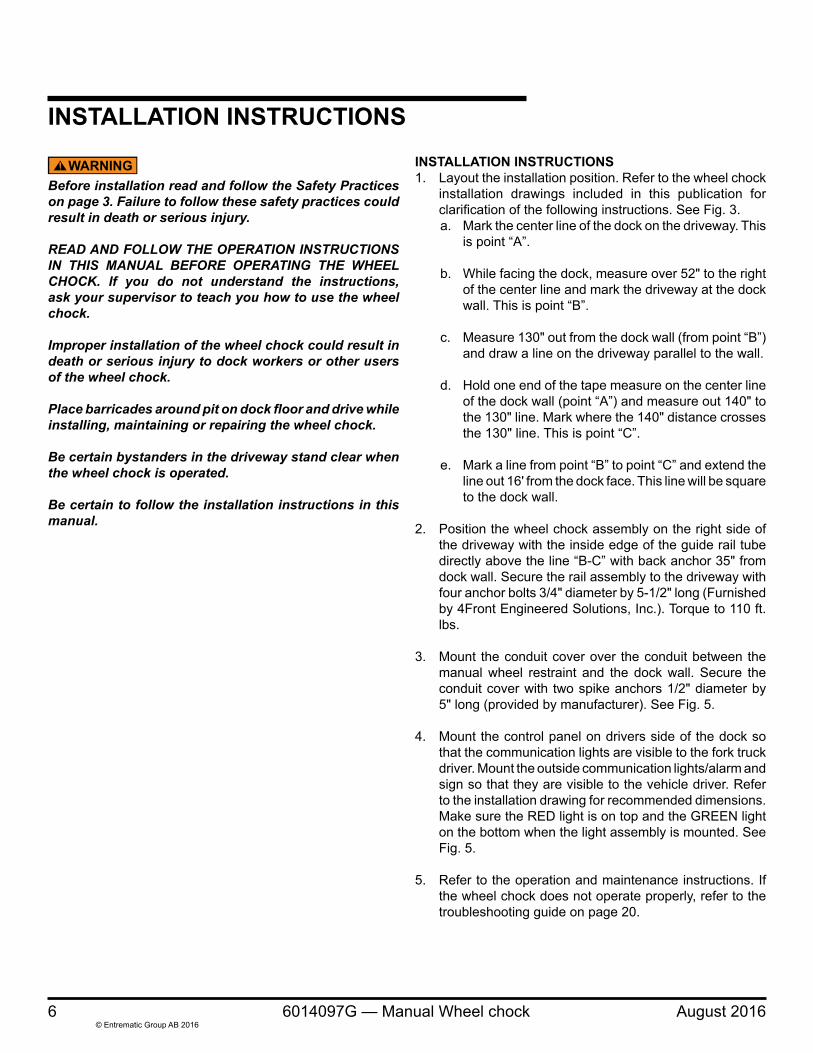
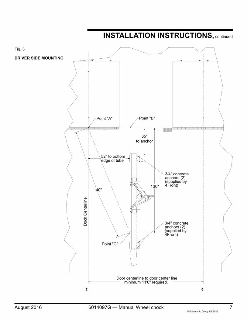
INSTALLATION INSTRUCTIONS1. Layout the installation position. Refer to the wheel chock
installation drawings included in this publication for clarification of the following instructions. See Fig. 3.a. Mark the center line of the dock on the driveway. This
is point “A”.
b. While facing the dock, measure over 52" to the right of the center line and mark the driveway at the dock wall. This is point “B”.
c. Measure 130" out from the dock wall (from point “B”) and draw a line on the driveway parallel to the wall.
d. Hold one end of the tape measure on the center line of the dock wall (point “A”) and measure out 140" to the 130" line. Mark where the 140" distance crosses the 130" line. This is point “C”.
e. Mark a line from point “B” to point “C” and extend the line out 16' from the dock face. This line will be square to the dock wall.
2. Position the wheel chock assembly on the right side of the driveway with the inside edge of the guide rail tube directly above the line “B-C” with back anchor 35" from dock wall. Secure the rail assembly to the driveway with four anchor bolts 3/4" diameter by 5-1/2" long (Furnished by 4Front Engineered Solutions, Inc.). Torque to 110 ft. lbs.
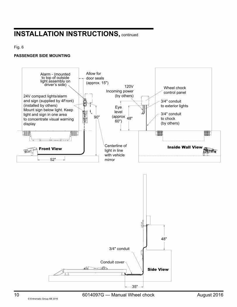
3. Mount the conduit cover over the conduit between the manual wheel restraint and the dock wall. Secure the conduit cover with two spike anchors 1/2" diameter by 5" long (provided by manufacturer). See Fig. 5.
4. Mount the control panel on drivers side of the dock so that the communication lights are visible to the fork truck driver. Mount the outside communication lights/alarm and sign so that they are visible to the vehicle driver. Refer to the installation drawing for recommended dimensions. Make sure the RED light is on top and the GREEN light on the bottom when the light assembly is mounted. See Fig. 5.
5. Refer to the operation and maintenance instructions. If the wheel chock does not operate properly, refer to the troubleshooting guide on page 20.
August 2016 6014097G — Manual Wheel chock 7© Entrematic Group AB 2016
INSTALLATION INSTRUCTIONS, continued
Fig. 3
DRIVER SIDE MOUNTING
35"to anchor
130"140"
Door centerline to door center lineminimum 11'6" required.
52" to bottomedge of tube
Doc
k C
ente
rline
Point "B"Point "A"
Point "C"
3/4" concreteanchors (2)(supplied by4Front)
3/4" concreteanchors (2)(supplied by4Front)
8 6014097G — Manual Wheel chock August 2016© Entrematic Group AB 2016
INSTALLATION INSTRUCTIONS, continued
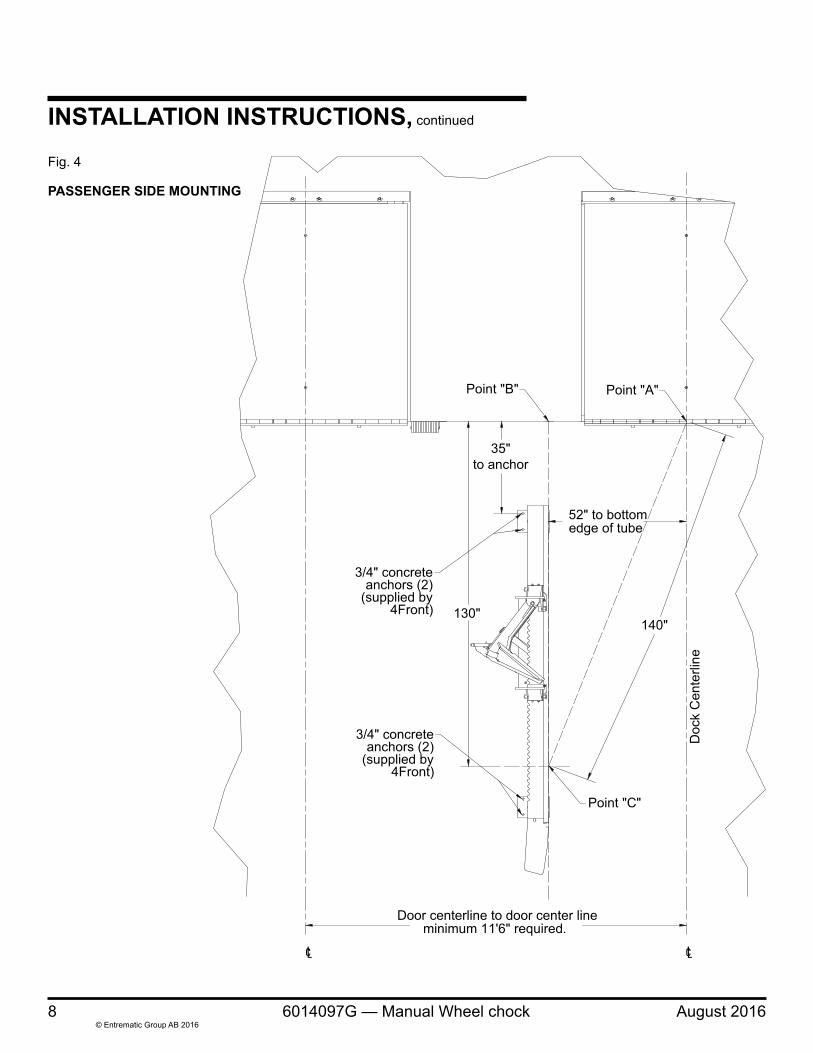
PASSENGER SIDE MOUNTING
35"to anchor
130"140"
Door centerline to door center lineminimum 11'6" required.
52" to bottomedge of tube
Doc
k C
ente
rline
Point "B" Point "A"
Point "C"
3/4" concreteanchors (2)
(supplied by4Front)
3/4" concreteanchors (2)
(supplied by4Front)
Fig. 4

August 2016 6014097G — Manual Wheel chock 9© Entrematic Group AB 2016
INSTALLATION INSTRUCTIONS, continued
90"
52"
Front View
35"
48"
3/4" conduit
Side View
24V compact lights/alarmand sign (supplied by 4Front)(installed by others)Mount sign below light. Keeplight and sign in one areato concentrate visual warningdisplay
48"
Eyelevel
(approx60”)
Inside Wall View
Wheel chockcontrol panel
120VIncoming power
(by others)
3/4" conduitto chock(by others)
3/4" conduitto exterior lights
Allow fordoor seals(approx. 15")
Centerline oflight in linewith vehiclemirror
Alarm - (mounted to top of outside
light assembly on driver’s side)
Conduit cover
Fig. 5
DRIVER SIDE MOUNTING
10 6014097G — Manual Wheel chock August 2016© Entrematic Group AB 2016
INSTALLATION INSTRUCTIONS, continued
Fig. 6
90"
Front View
35"
48"
3/4" conduit
Side View
24V compact lights/alarmand sign (supplied by 4Front)(installed by others)Mount sign below light. Keeplight and sign in one areato concentrate visual warningdisplay
48"
Eyelevel
(approx60")
Inside Wall View
Wheel chockcontrol panel
120VIncoming power
(by others)
3/4" conduitto chock(by others)
3/4" conduitto exterior lights
Allow fordoor seals(approx. 15")
Centerline oflight in linewith vehiclemirror52"
Alarm - (mounted to top of outside
light assembly on driver’s side)
Conduit cover
PASSENGER SIDE MOUNTING
August 2016 6014097G — Manual Wheel chock 11© Entrematic Group AB 2016
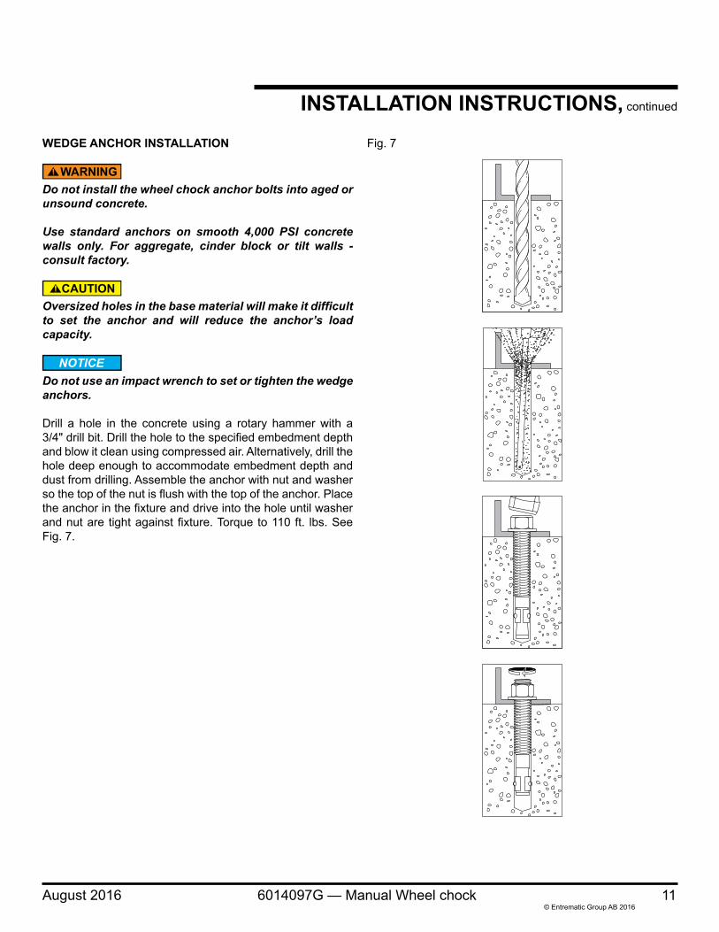
WEDGE ANCHOR INSTALLATION
Do not install the wheel chock anchor bolts into aged or unsound concrete.
Use standard anchors on smooth 4,000 PSI concrete walls only. For aggregate, cinder block or tilt walls - consult factory.
Oversized holes in the base material will make it difficult to set the anchor and will reduce the anchor’s load capacity.
Do not use an impact wrench to set or tighten the wedge anchors.
Drill a hole in the concrete using a rotary hammer with a 3/4" drill bit. Drill the hole to the specified embedment depth and blow it clean using compressed air. Alternatively, drill the hole deep enough to accommodate embedment depth and dust from drilling. Assemble the anchor with nut and washer so the top of the nut is flush with the top of the anchor. Place the anchor in the fixture and drive into the hole until washer and nut are tight against fixture. Torque to 110 ft. lbs. See Fig. 7.
Fig. 7
INSTALLATION INSTRUCTIONS, continued
12 6014097G — Manual Wheel chock August 2016© Entrematic Group AB 2016
INSTALLATION INSTRUCTIONS, continued
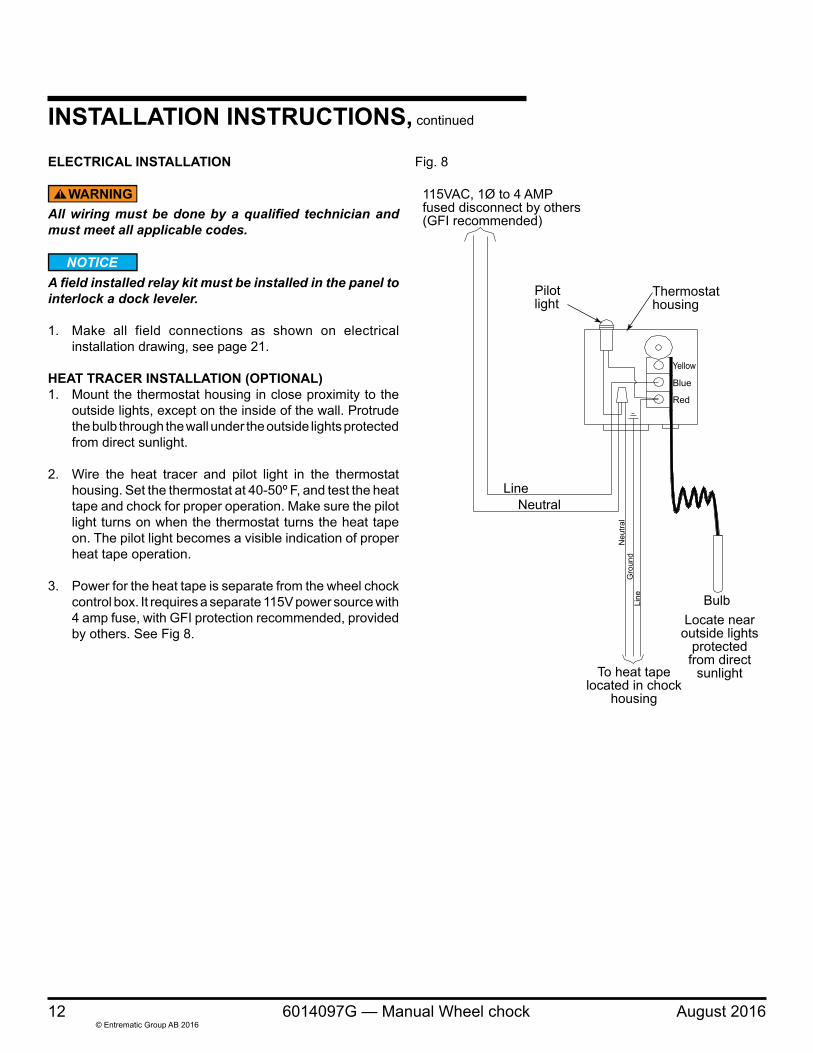
Fig. 8ELECTRICAL INSTALLATION
All wiring must be done by a qualified technician and must meet all applicable codes.
A field installed relay kit must be installed in the panel to interlock a dock leveler.
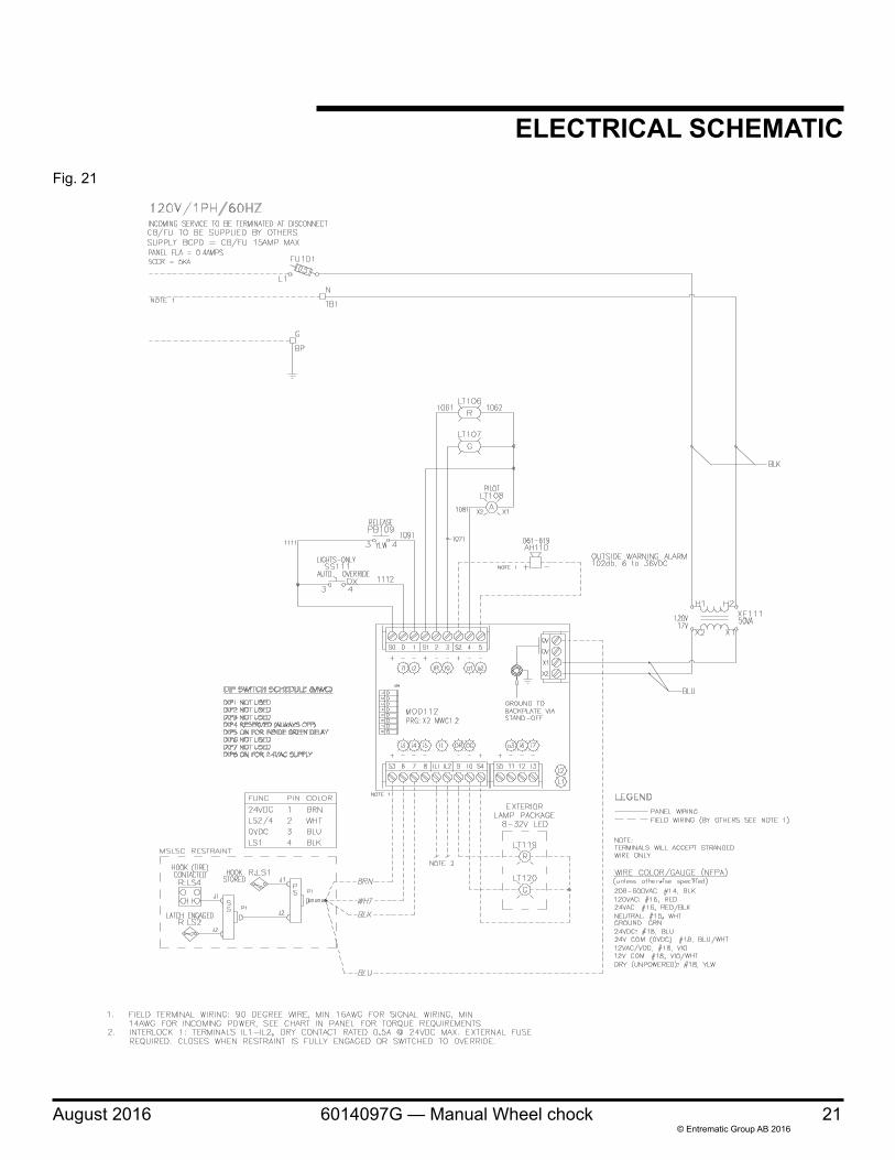
1. Make all field connections as shown on electrical installation drawing, see page 21.
HEAT TRACER INSTALLATION (OPTIONAL)1. Mount the thermostat housing in close proximity to the
outside lights, except on the inside of the wall. Protrude the bulb through the wall under the outside lights protected from direct sunlight.
2. Wire the heat tracer and pilot light in the thermostat housing. Set the thermostat at 40-50º F, and test the heat tape and chock for proper operation. Make sure the pilot light turns on when the thermostat turns the heat tape on. The pilot light becomes a visible indication of proper heat tape operation.
3. Power for the heat tape is separate from the wheel chock control box. It requires a separate 115V power source with 4 amp fuse, with GFI protection recommended, provided by others. See Fig 8.
Pilotlight
Thermostathousing
LineNeutral
Bulb
To heat tapelocated in chock
housing
Locate nearoutside lights
protectedfrom direct
sunlight
Yellow
Blue
Red
115VAC, 1Ø to 4 AMPfused disconnect by others(GFI recommended)
Line
Neu
tral
Gro
und
August 2016 6014097G — Manual Wheel chock 13© Entrematic Group AB 2016
OPERATING INSTRUCTIONSUse these instructions for normal operations.
Before operating the wheel chock, read and follow the Safety Practices, Warnings, and Operation instructions contained in this manual. Use by untrained people could result in death or serious injury.
Do not use the wheel chock if it looks broken or does not seem to work right. Tell your supervisor at once.
Do not load or unload any vehicle unless you make certain the wheel chock has securely engaged the tire and set the brakes. If the wheel chock will not chock the vehicle's tire for any reason, BE CERTAIN TO MANUALLY CHOCK THE VEHICLE WHEELS BEFORE LOADING OR UNLOADING.
Enter the vehicle only when the GREEN signal light on the control panel is on. You must check the GREEN signal light each time that the vehicle is entered. If the GREEN light goes off at any time during loading operations, immediately cease loading operations and check the wheel chock to ensure that it is securely hitched.
If the power to the wheel chock is interrupted, immediately cease operations and check the unit. consult the troubleshooting instructions to reset the lights when power resumes.
Vehicles leaving or moving when loading and unloading are in process could result in death or serious injury.
Do not press the release button or release the chock arm with dock leveler lip in trailer. Always return the dock leveler to its stored position at dock level before pressing the release push button or allowing the vehicle to leave.
Failure to follow these safety practices may result in death or serious injury.
14 6014097G — Manual Wheel chock August 2016© Entrematic Group AB 2016
OPERATING INSTRUCTIONS, continued
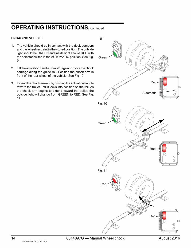
ENGAGING VEHICLE
1. The vehicle should be in contact with the dock bumpers and the wheel restraint in the stored position. The outside light should be GREEN and inside light should RED with the selector switch in the AUTOMATIC position. See Fig. 9.
2. Lift the activation handle from storage and move the chock carriage along the guide rail. Position the chock arm in front of the rear wheel of the vehicle. See Fig 10.
3. Extend the chock arm out by pushing the activation handle toward the trailer until it locks into position on the rail. As the chock arm begins to extend toward the trailer, the outside light will change from GREEN to RED. See Fig. 11.
Fig. 10
Fig. 11
Fig. 9
Green
Red
Automatic
Green
Red
Red
Red
August 2016 6014097G — Manual Wheel chock 15© Entrematic Group AB 2016
Fig. 13
Fig. 12
Red
Green
OPERATING INSTRUCTIONS, continued
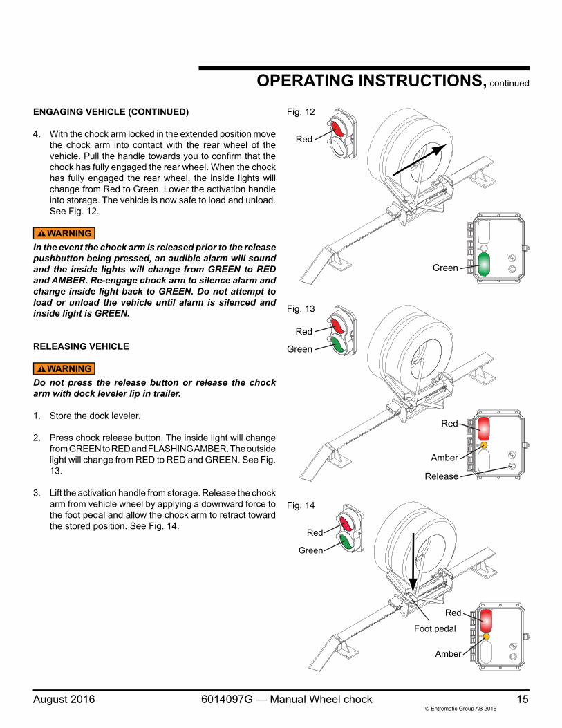
ENGAGING VEHICLE (CONTINUED)
4. With the chock arm locked in the extended position move the chock arm into contact with the rear wheel of the vehicle. Pull the handle towards you to confirm that the chock has fully engaged the rear wheel. When the chock has fully engaged the rear wheel, the inside lights will change from Red to Green. Lower the activation handle into storage. The vehicle is now safe to load and unload. See Fig. 12.
In the event the chock arm is released prior to the release pushbutton being pressed, an audible alarm will sound and the inside lights will change from GREEN to RED and AMBER. Re-engage chock arm to silence alarm and change inside light back to GREEN. Do not attempt to load or unload the vehicle until alarm is silenced and inside light is GREEN.
RELEASING VEHICLE
Do not press the release button or release the chock arm with dock leveler lip in trailer.
1. Store the dock leveler.
2. Press chock release button. The inside light will change from GREEN to RED and FLASHING AMBER. The outside light will change from RED to RED and GREEN. See Fig. 13.
3. Lift the activation handle from storage. Release the chock arm from vehicle wheel by applying a downward force to the foot pedal and allow the chock arm to retract toward the stored position. See Fig. 14.
Fig. 14
Foot pedal
Red
Green
Red
Amber
Red
Green
Red
Amber
Release
16 6014097G — Manual Wheel chock August 2016© Entrematic Group AB 2016
Fig. 15
Green
Red
OPERATING INSTRUCTIONS, continued
RELEASING VEHICLE (CONTINUED)
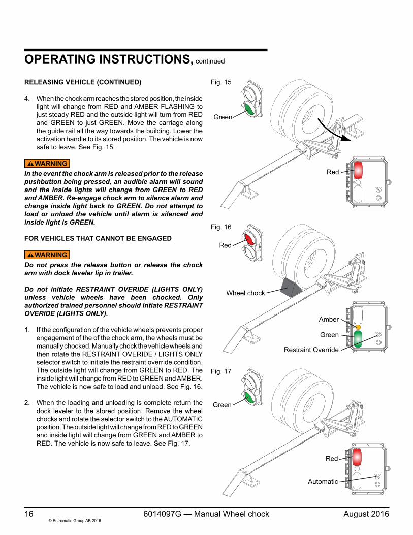
4. When the chock arm reaches the stored position, the inside light will change from RED and AMBER FLASHING to just steady RED and the outside light will turn from RED and GREEN to just GREEN. Move the carriage along the guide rail all the way towards the building. Lower the activation handle to its stored position. The vehicle is now safe to leave. See Fig. 15.
In the event the chock arm is released prior to the release pushbutton being pressed, an audible alarm will sound and the inside lights will change from GREEN to RED and AMBER. Re-engage chock arm to silence alarm and change inside light back to GREEN. Do not attempt to load or unload the vehicle until alarm is silenced and inside light is GREEN.
FOR VEHICLES THAT CANNOT BE ENGAGED
Do not press the release button or release the chock arm with dock leveler lip in trailer.
Do not initiate RESTRAINT OVERIDE (LIGHTS ONLY) unless vehicle wheels have been chocked. Only authorized trained personnel should intiate RESTRAINT OVERIDE (LIGHTS ONLY).
1. If the configuration of the vehicle wheels prevents proper engagement of the of the chock arm, the wheels must be manually chocked. Manually chock the vehicle wheels and then rotate the RESTRAINT OVERIDE / LIGHTS ONLY selector switch to initiate the restraint override condition. The outside light will change from GREEN to RED. The inside light will change from RED to GREEN and AMBER. The vehicle is now safe to load and unload. See Fig. 16.
2. When the loading and unloading is complete return the dock leveler to the stored position. Remove the wheel chocks and rotate the selector switch to the AUTOMATIC position. The outside light will change from RED to GREEN and inside light will change from GREEN and AMBER to RED. The vehicle is now safe to leave. See Fig. 17.
Fig. 16
Red
Wheel chock
Green
Amber
Restraint Override
Fig. 17
Green
Red
Automatic
August 2016 6014097G — Manual Wheel chock 17© Entrematic Group AB 2016
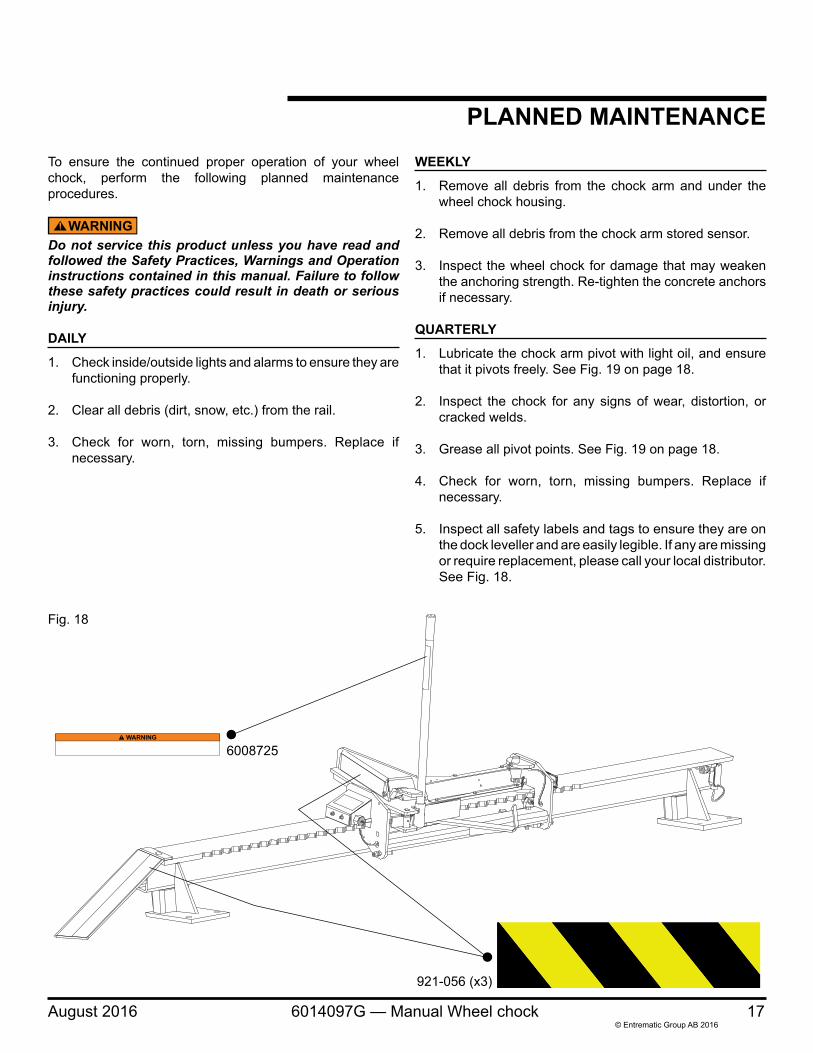
Fig. 18
PLANNED MAINTENANCE
921-056 (x3)
6008725
To ensure the continued proper operation of your wheel chock, perform the following planned maintenance procedures.
Do not service this product unless you have read and followed the Safety Practices, Warnings and Operation instructions contained in this manual. Failure to follow these safety practices could result in death or serious injury.
DAILY
1. Check inside/outside lights and alarms to ensure they are functioning properly.
2. Clear all debris (dirt, snow, etc.) from the rail.
3. Check for worn, torn, missing bumpers. Replace if necessary.
WEEKLY
1. Remove all debris from the chock arm and under the wheel chock housing.
2. Remove all debris from the chock arm stored sensor.
3. Inspect the wheel chock for damage that may weaken the anchoring strength. Re-tighten the concrete anchors if necessary.
QUARTERLY
1. Lubricate the chock arm pivot with light oil, and ensure that it pivots freely. See Fig. 19 on page 18.
2. Inspect the chock for any signs of wear, distortion, or cracked welds.
3. Grease all pivot points. See Fig. 19 on page 18.
4. Check for worn, torn, missing bumpers. Replace if necessary.
5. Inspect all safety labels and tags to ensure they are on the dock leveller and are easily legible. If any are missing or require replacement, please call your local distributor. See Fig. 18.
18 6014097G — Manual Wheel chock August 2016© Entrematic Group AB 2016
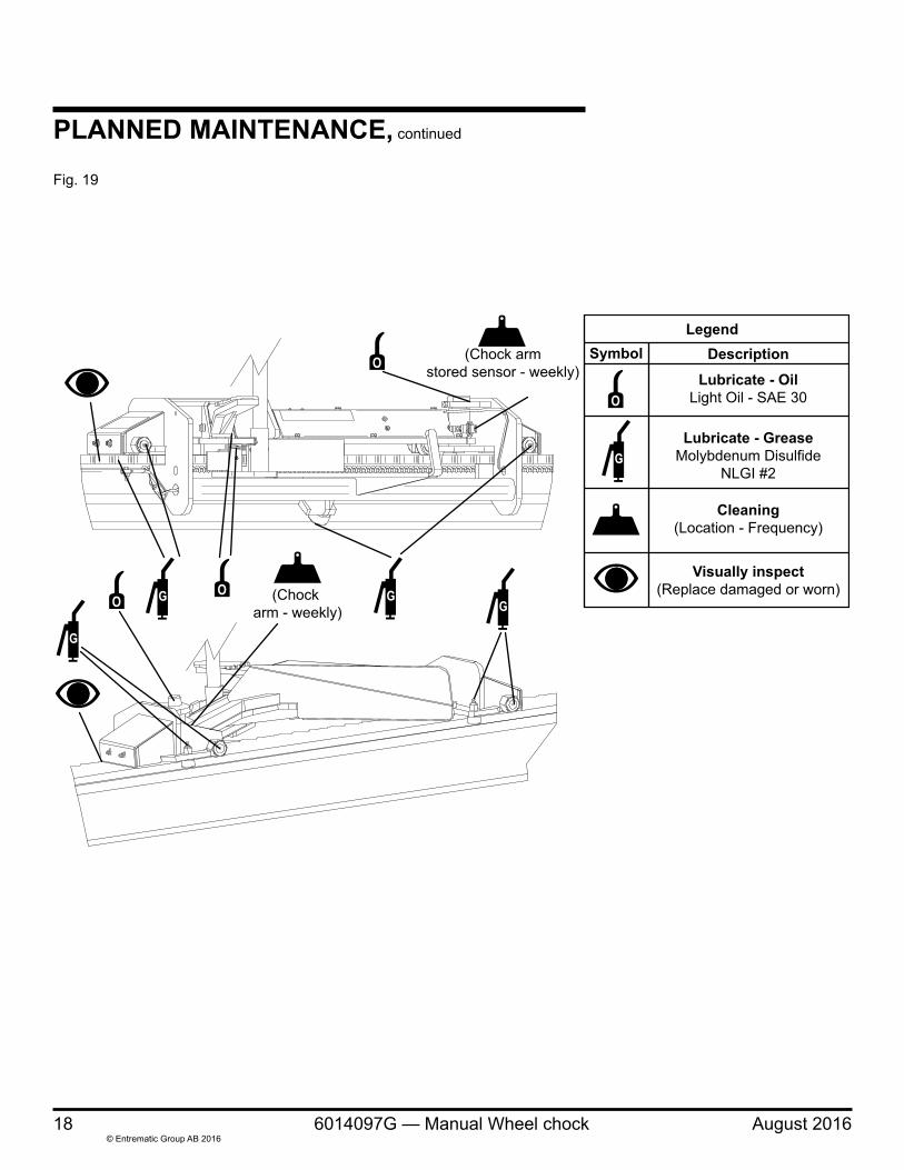
PLANNED MAINTENANCE, continued
LegendSymbol Description
Lubricate - OilLight Oil - SAE 30
Lubricate - GreaseMolybdenum Disulfide
NLGI #2
Cleaning(Location - Frequency)
Visually inspect(Replace damaged or worn)
(Chock armstored sensor - weekly)
(Chock arm - weekly)
Fig. 19
August 2016 6014097G — Manual Wheel chock 19© Entrematic Group AB 2016
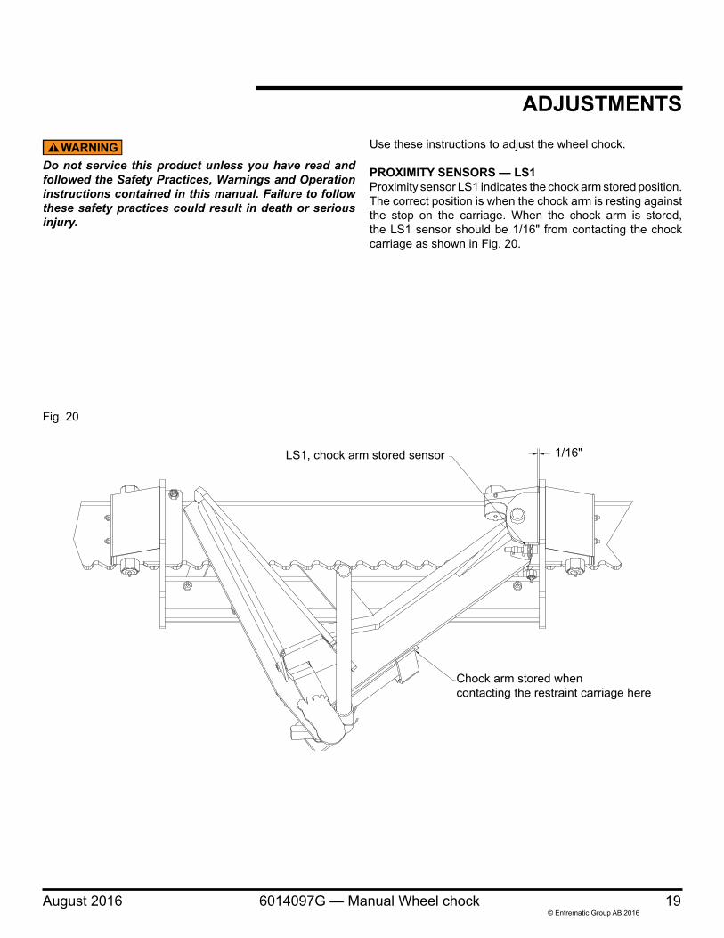
ADJUSTMENTS
Fig. 20
Do not service this product unless you have read and followed the Safety Practices, Warnings and Operation instructions contained in this manual. Failure to follow these safety practices could result in death or serious injury.
Use these instructions to adjust the wheel chock.
PROXIMITY SENSORS — LS1Proximity sensor LS1 indicates the chock arm stored position. The correct position is when the chock arm is resting against the stop on the carriage. When the chock arm is stored, the LS1 sensor should be 1/16" from contacting the chock carriage as shown in Fig. 20.
1/16"
Chock arm stored whencontacting the restraint carriage here
LS1, chock arm stored sensor
20 6014097G — Manual Wheel chock August 2016© Entrematic Group AB 2016
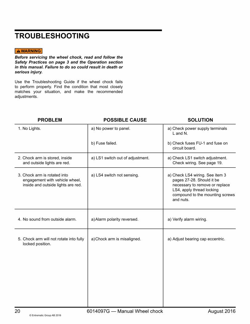
TROUBLESHOOTING
Before servicing the wheel chock, read and follow the Safety Practices on page 3 and the Operation section in this manual. Failure to do so could result in death or serious injury.
Use the Troubleshooting Guide if the wheel chock fails to perform properly. Find the condition that most closely matches your situation, and make the recommended adjustments.
PROBLEM POSSIBLE CAUSE SOLUTION 1. No Lights. a) No power to panel. a) Check power supply terminals L and N.
b) Fuse failed. b) Check fuses FU-1 and fuse on circuit board.
2. Chock arm is stored, inside a) LS1 switch out of adjustment. a) Check LS1 switch adjustment. and outside lights are red. Check wiring. See page 19.
3. Chock arm is rotated into a) LS4 switch not sensing. a) Check LS4 wiring. See item 3 engagement with vehicle wheel, pages 27-28. Should it be inside and outside lights are red. necessary to remove or replace LS4, apply thread locking compound to the mounting screws and nuts.
4. No sound from outside alarm. a) Alarm polarity reversed. a) Verify alarm wiring.
5. Chock arm will not rotate into fully a) Chock arm is misaligned. a) Adjust bearing cap eccentric. locked position.
August 2016 6014097G — Manual Wheel chock 21© Entrematic Group AB 2016
ELECTRICAL SCHEMATICFig. 21
22 6014097G — Manual Wheel chock August 2016© Entrematic Group AB 2016
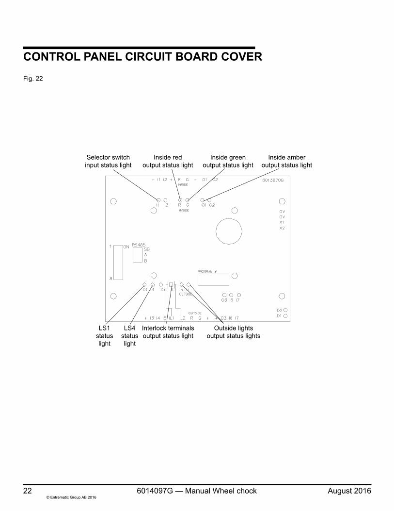
CONTROL PANEL CIRCUIT BOARD COVERFig. 22
Selector switchinput status light
LS1statuslight
LS4statuslight
Interlock terminalsoutput status light
Outside lightsoutput status lights
Inside redoutput status light
Inside greenoutput status light
Inside amberoutput status light
August 2016 6014097G — Manual Wheel chock 23© Entrematic Group AB 2016
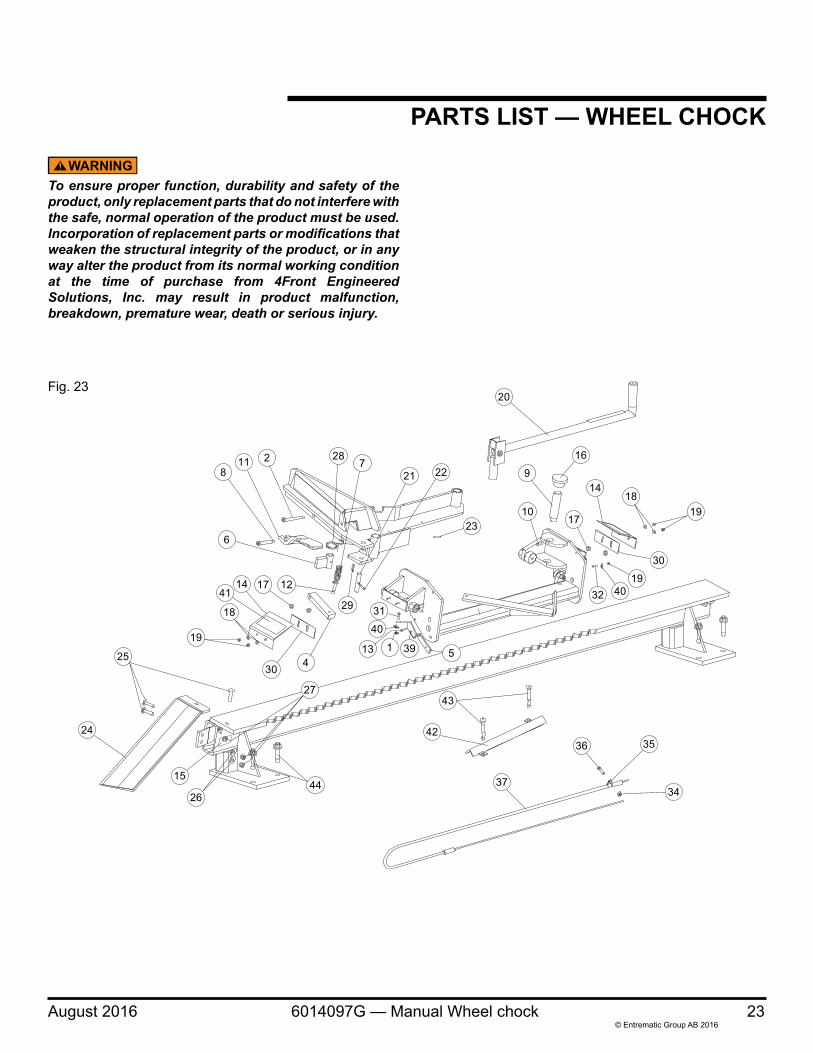
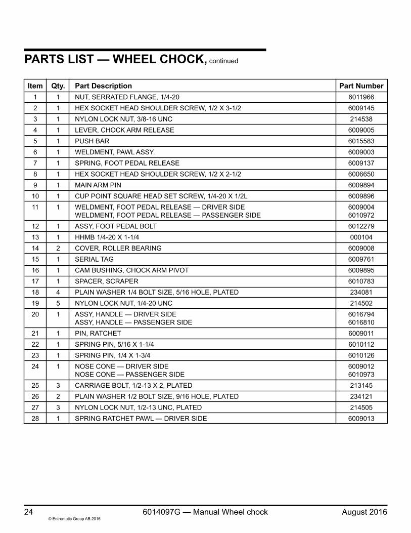
To ensure proper function, durability and safety of the product, only replacement parts that do not interfere with the safe, normal operation of the product must be used. Incorporation of replacement parts or modifications that weaken the structural integrity of the product, or in any way alter the product from its normal working condition at the time of purchase from 4Front Engineered Solutions, Inc. may result in product malfunction, breakdown, premature wear, death or serious injury.
PARTS LIST — WHEEL CHOCK
20
9
16
10
1418
19
30
32 4019
27
26
24
15
25
19
18
1441
12
29
17
6
30 4
23
22217
282118
34
3536
44
43
42
37
31
40
113 39 5
17
Fig. 23
24 6014097G — Manual Wheel chock August 2016© Entrematic Group AB 2016
PARTS LIST — WHEEL CHOCK, continued
Item Qty. Part Description Part Number 1 1 NUT, SERRATED FLANGE, 1/4-20 6011966 2 1 HEX SOCKET HEAD SHOULDER SCREW, 1/2 X 3-1/2 6009145 3 1 NYLON LOCK NUT, 3/8-16 UNC 214538 4 1 LEVER, CHOCK ARM RELEASE 6009005 5 1 PUSH BAR 6015583 6 1 WELDMENT, PAWL ASSY. 6009003 7 1 SPRING, FOOT PEDAL RELEASE 6009137 8 1 HEX SOCKET HEAD SHOULDER SCREW, 1/2 X 2-1/2 6006650 9 1 MAIN ARM PIN 6009894 10 1 CUP POINT SQUARE HEAD SET SCREW, 1/4-20 X 1/2L 6009896 11 1 WELDMENT, FOOT PEDAL RELEASE — DRIVER SIDE 6009004 WELDMENT, FOOT PEDAL RELEASE — PASSENGER SIDE 6010972 12 1 ASSY, FOOT PEDAL BOLT 6012279 13 1 HHMB 1/4-20 X 1-1/4 000104 14 2 COVER, ROLLER BEARING 6009008 15 1 SERIAL TAG 6009761 16 1 CAM BUSHING, CHOCK ARM PIVOT 6009895 17 1 SPACER, SCRAPER 6010783 18 4 PLAIN WASHER 1/4 BOLT SIZE, 5/16 HOLE, PLATED 234081 19 5 NYLON LOCK NUT, 1/4-20 UNC 214502 20 1 ASSY, HANDLE — DRIVER SIDE 6016794 ASSY, HANDLE — PASSENGER SIDE 6016810 21 1 PIN, RATCHET 6009011 22 1 SPRING PIN, 5/16 X 1-1/4 6010112 23 1 SPRING PIN, 1/4 X 1-3/4 6010126 24 1 NOSE CONE — DRIVER SIDE 6009012 NOSE CONE — PASSENGER SIDE 6010973 25 3 CARRIAGE BOLT, 1/2-13 X 2, PLATED 213145 26 2 PLAIN WASHER 1/2 BOLT SIZE, 9/16 HOLE, PLATED 234121 27 3 NYLON LOCK NUT, 1/2-13 UNC, PLATED 214505 28 1 SPRING RATCHET PAWL — DRIVER SIDE 6009013
August 2016 6014097G — Manual Wheel chock 25© Entrematic Group AB 2016
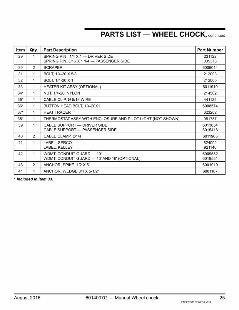
Item Qty. Part Description Part Number 29 1 SPRING PIN , 1/4 X 1 — DRIVER SIDE 231122 SPRING PIN, 3/16 X 1 1/4 — PASSENGER SIDE 035373 30 2 SCRAPER 6009014 31 1 BOLT, 1/4-20 X 5/8 212003 32 1 BOLT, 1/4-20 X 1 212005 33 1 HEATER KIT ASSY (OPTIONAL) 6011919 34* 1 NUT, 1/4-20, NYLON 214502 35* 1 CABLE CLIP, Ø 5/16 WIRE 441125 36* 1 BUTTON HEAD BOLT, 1/4-20X1 6008574 37* 1 HEAT TRACER 623202 38* 1 THERMOSTAT ASSY WITH ENCLOSURE AND PILOT LIGHT (NOT SHOWN) 061787 39 1 CABLE SUPPORT — DRIVER SIDE 6013634 CABLE SUPPORT — PASSENGER SIDE 6015418 40 2 CABLE CLAMP, Ø1/4 6011965 41 1 LABEL, SERCO 824002 LABEL, KELLEY 921140 42 1 WDMT, CONDUIT GUARD — 10' 6009532 WDMT, CONDUIT GUARD — 13' AND 16' (OPTIONAL) 6019531 43 2 ANCHOR, SPIKE, 1/2 X 5" 6001910 44 4 ANCHOR, WEDGE 3/4 X 5-1/2" 6001187
PARTS LIST — WHEEL CHOCK, continued
* Included in item 33.
26 6014097G — Manual Wheel chock August 2016© Entrematic Group AB 2016
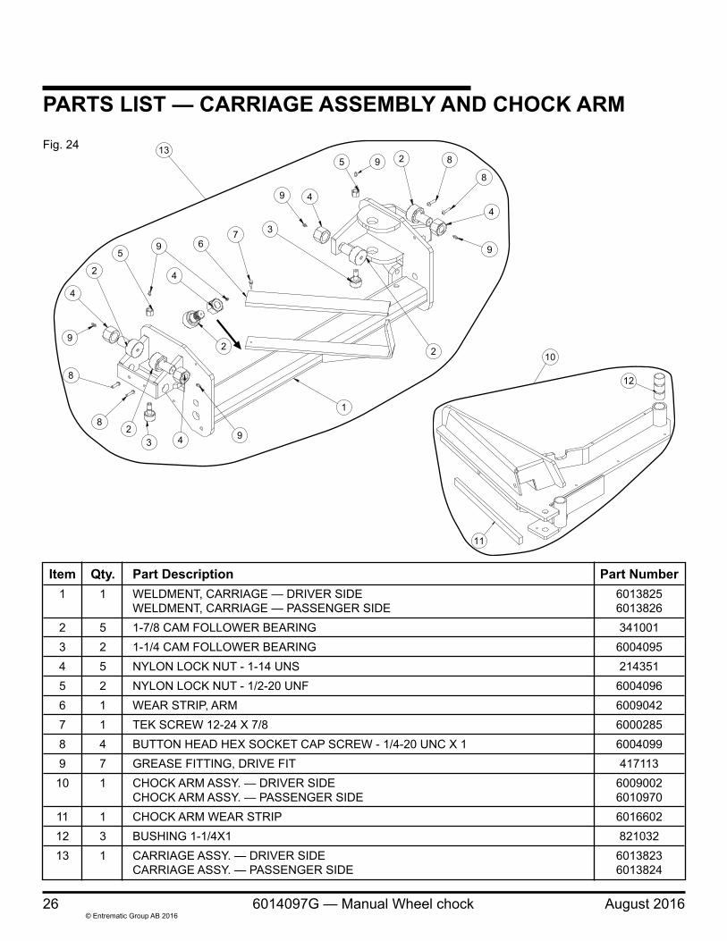
PARTS LIST — CARRIAGE ASSEMBLY AND CHOCK ARMFig. 24
Item Qty. Part Description Part Number 1 1 WELDMENT, CARRIAGE — DRIVER SIDE 6013825 WELDMENT, CARRIAGE — PASSENGER SIDE 6013826 2 5 1-7/8 CAM FOLLOWER BEARING 341001 3 2 1-1/4 CAM FOLLOWER BEARING 6004095 4 5 NYLON LOCK NUT - 1-14 UNS 214351 5 2 NYLON LOCK NUT - 1/2-20 UNF 6004096 6 1 WEAR STRIP, ARM 6009042 7 1 TEK SCREW 12-24 X 7/8 6000285 8 4 BUTTON HEAD HEX SOCKET CAP SCREW - 1/4-20 UNC X 1 6004099 9 7 GREASE FITTING, DRIVE FIT 417113 10 1 CHOCK ARM ASSY. — DRIVER SIDE 6009002 CHOCK ARM ASSY. — PASSENGER SIDE 6010970 11 1 CHOCK ARM WEAR STRIP 6016602 12 3 BUSHING 1-1/4X1 821032 13 1 CARRIAGE ASSY. — DRIVER SIDE 6013823 CARRIAGE ASSY. — PASSENGER SIDE 6013824
4
5 9 2 8
8
4
9
2
4
2
1
9432
8
8
9
4
2
59 6
7 3
9
13
12
11
10
August 2016 6014097G — Manual Wheel chock 27© Entrematic Group AB 2016
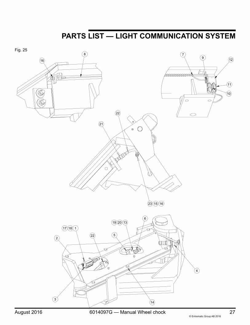
PARTS LIST — LIGHT COMMUNICATION SYSTEMFig. 25
16
8 79 12
11
10
17 18 1
22
19 1320
5
6
4
143
21
22
23 15 16
2
28 6014097G — Manual Wheel chock August 2016© Entrematic Group AB 2016
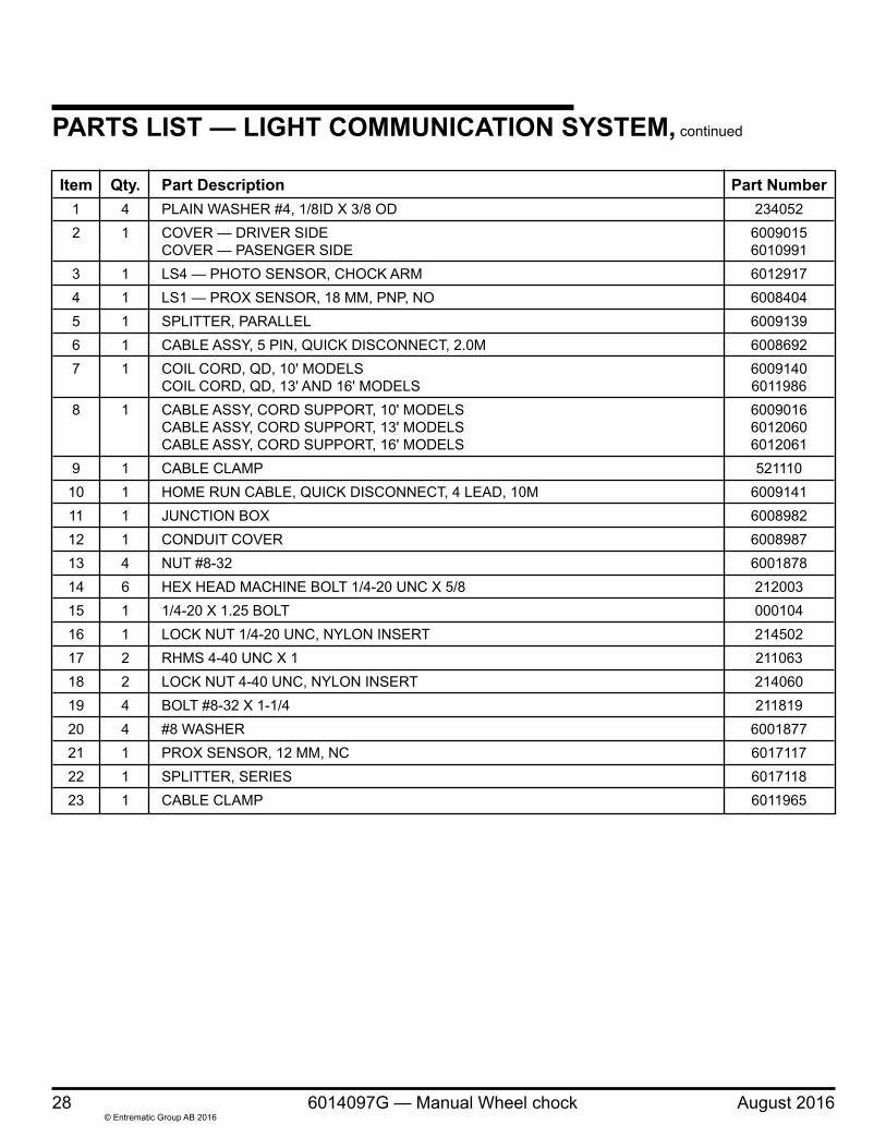
PARTS LIST — LIGHT COMMUNICATION SYSTEM, continued
Item Qty. Part Description Part Number 1 4 PLAIN WASHER #4, 1/8ID X 3/8 OD 234052 2 1 COVER — DRIVER SIDE 6009015 COVER — PASENGER SIDE 6010991 3 1 LS4 — PHOTO SENSOR, CHOCK ARM 6012917 4 1 LS1 — PROX SENSOR, 18 MM, PNP, NO 6008404 5 1 SPLITTER, PARALLEL 6009139 6 1 CABLE ASSY, 5 PIN, QUICK DISCONNECT, 2.0M 6008692 7 1 COIL CORD, QD, 10' MODELS 6009140 COIL CORD, QD, 13' AND 16' MODELS 6011986 8 1 CABLE ASSY, CORD SUPPORT, 10' MODELS 6009016 CABLE ASSY, CORD SUPPORT, 13' MODELS 6012060 CABLE ASSY, CORD SUPPORT, 16' MODELS 6012061 9 1 CABLE CLAMP 521110 10 1 HOME RUN CABLE, QUICK DISCONNECT, 4 LEAD, 10M 6009141 11 1 JUNCTION BOX 6008982 12 1 CONDUIT COVER 6008987 13 4 NUT #8-32 6001878 14 6 HEX HEAD MACHINE BOLT 1/4-20 UNC X 5/8 212003 15 1 1/4-20 X 1.25 BOLT 000104 16 1 LOCK NUT 1/4-20 UNC, NYLON INSERT 214502 17 2 RHMS 4-40 UNC X 1 211063 18 2 LOCK NUT 4-40 UNC, NYLON INSERT 214060 19 4 BOLT #8-32 X 1-1/4 211819 20 4 #8 WASHER 6001877 21 1 PROX SENSOR, 12 MM, NC 6017117 22 1 SPLITTER, SERIES 6017118 23 1 CABLE CLAMP 6011965
August 2016 6014097G — Manual Wheel chock 29© Entrematic Group AB 2016
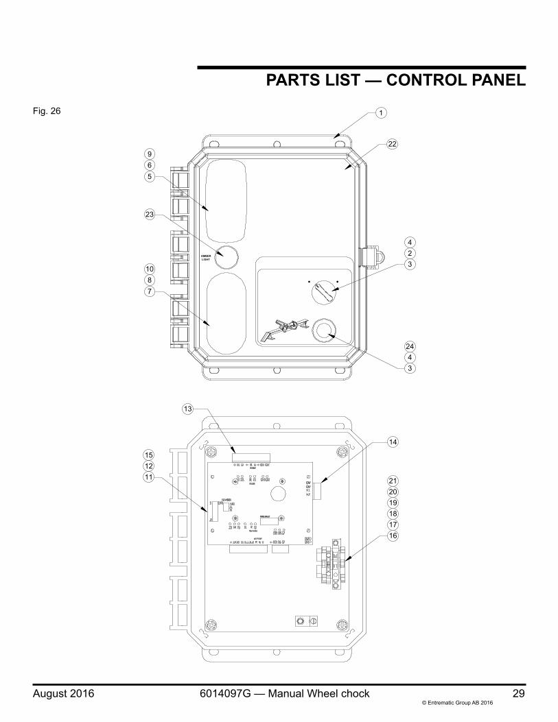
PARTS LIST — CONTROL PANEL
965
1087
23
1
22
423
2443
13
151211
14
212019181716
Fig. 26
30 6014097G — Manual Wheel chock August 2016© Entrematic Group AB 2016
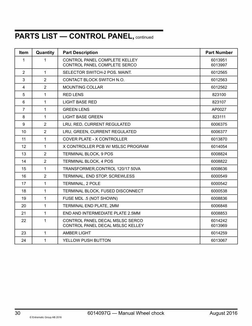
Item Quantity Part Description Part Number 1 1 CONTROL PANEL COMPLETE KELLEY 6013951 CONTROL PANEL COMPLETE SERCO 6013997
2 1 SELECTOR SWITCH-2 POS. MAINT. 6012565
3 2 CONTACT BLOCK SWITCH N.O. 6012563
4 2 MOUNTING COLLAR 6012562
5 1 RED LENS 823100
6 1 LIGHT BASE RED 823107
7 1 GREEN LENS AP0027
8 1 LIGHT BASE GREEN 823111
9 2 LRU, RED, CURRENT REGULATED 6006375
10 2 LRU, GREEN, CURRENT REGULATED 6006377
11 1 COVER PLATE - X CONTROLLER 6013870
12 1 X CONTROLLER PCB W/ MSLSC PROGRAM 6014054
13 2 TERMINAL BLOCK, 9 POS 6008824
14 2 TERMINAL BLOCK, 4 POS 6008822
15 1 TRANSFORMER,CONTROL 120/17 50VA 6008636
16 2 TERMINAL, END STOP, SCREWLESS 6000549
17 1 TERMINAL, 2 POLE 6000542
18 1 TERMINAL BLOCK, FUSED DISCONNECT 6000538
19 1 FUSE MDL .5 (NOT SHOWN) 6008836
20 1 TERMINAL END PLATE, 2MM 6006848
21 1 END AND INTERMEDIATE PLATE 2.5MM 6008853
22 1 CONTROL PANEL DECAL MSLSC SERCO 6014242 CONTROL PANEL DECAL MSLSC KELLEY 6013969
23 1 AMBER LIGHT 6014259
24 1 YELLOW PUSH BUTTON 6013067
PARTS LIST — CONTROL PANEL, continued
August 2016 6014097G — Manual Wheel chock 31© Entrematic Group AB 2016
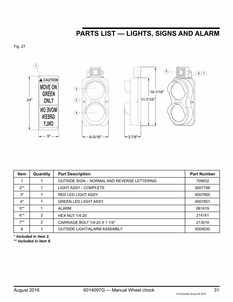
Item Quantity Part Description Part Number 1 1 OUTSIDE SIGN – NORMAL AND REVERSE LETTERING 709832
2** 1 LIGHT ASSY - COMPLETE 6007798
3* 1 RED LED LIGHT ASSY. 6007800
4* 1 GREEN LED LIGHT ASSY. 6007801
5** 1 ALARM 061619
6** 2 HEX NUT 1/4-20 214161
7** 2 CARRIAGE BOLT 1/4-20 X 1 1/4" 213019
8 1 OUTSIDE LIGHT/ALARM ASSEMBLY 6009530
* Included in item 2.** Included in item 8.
24"
9"
1
11-7/16"
3-7/8"6-5/16"
14-1/16"
2
3
4
56 7
Fig. 27
PARTS LIST — LIGHTS, SIGNS AND ALARM

32 6014097G — Manual Wheel chock August 2016© Entrematic Group AB 2016
NOTES

August 2016 6014097G — Manual Wheel chock 33© Entrematic Group AB 2016
NOTES

34 6014097G — Manual Wheel chock August 2016© Entrematic Group AB 2016
NOTES
August 2016 6014097G — Manual Wheel chock 35© Entrematic Group AB 2016
LIMITED WARRANTYTHIS LIMITED WARRANTY IS 4FRONT’S SOLE AND EXCLUSIVE WARRANTY WITH RESPECT TO THE WHEEL CHOCK AND IS IN LIEU OF ANY OTHER GUARANTEES OR WARRANTIES, EXPRESS OR IMPLIED.
4Front warrants that this WHEEL CHOCK will be free from flaws in material and workmanship under normal use for a period of one (1) year from the earlier of 1) 60 days after the date of initial shipment by 4Front, or 2) the date of installation of the WHEEL CHOCK by the original purchaser, provided that the owner maintains and operates the WHEEL CHOCK in accordance with this User’s Manual.
In the event that this WHEEL CHOCK proves deficient in material or workmanship within the applicable Limited Warranty period, owner shall so notify 4Front, and 4Front will, at its option:
1. Replace the WHEEL CHOCK, or the deficient portion(s) thereof, without charge to the owner; or
2. Alter or repair the WHEEL CHOCK, on site or elsewhere, without charge to the owner.
This Limited Warranty does not cover any failure caused by improper installation, abuse, improper operation, negligence, or failure to maintain and adjust the WHEEL CHOCK properly. Parts requiring replacement due to damage resulting from vehicle impact, abuse, or improper operation are not covered by this warranty. 4FRONT DISCLAIMS ANY RESPONSIBILITY OR LIABILITY FOR ANY LOSS OR DAMAGE OF ANY KIND (INCLUDING WITHOUT LIMITATION, DIRECT, INDIRECT, CONSEQUENTIAL OR PUNITIVE DAMAGES, OR LOST PROFITS OR LOST PRODUCTION) arising out of or related to the use, installation or maintenance of the WHEEL CHOCK (including premature product wear, product failure, property damage or bodily injury resulting from use of unauthorized replacement parts or modification of the WHEEL CHOCK). 4Front’s sole obligation with regard to a WHEEL CHOCK that is claimed to be deficient in material or workmanship shall be as set forth in this Limited Warranty. This Limited Warranty will be null and void if the original purchaser does not notify 4Front’s warranty department within ninety (90) days after the product deficiency is discovered.
THERE ARE NO WARRANTIES, EXPRESS OR IMPLIED, WHICH EXTEND BEYOND THE DESCRIPTION ON THE FACE HEREOF, INCLUDING, BUT NOT LIMITED TO, A WARRANTY OF MERCHANTABILITY OR OF FITNESS FOR A PARTICULAR PURPOSE, ALL OF WHICH 4Front HEREBY DISCLAIMS.
Your local 4Front Engineered Solutions, Inc. distributor is:
Please direct questions about your wheel chock to your local distributor or to 4Front Engineered Solutions, Inc.
Corporate Head Office:
1612 Hutton Dr. Suite 140Carrollton, TX. 75006Tel. (972) 466-0707Fax (972) 323-2661
Part No. 6014097G© Entrematic Group AB 2016
SAFETY-LOC®
SAFETY-CHOCK®
SURFACE CHOCK™
4Front Engineered Solutions®