Embed Size (px)
Citation preview

HWD0071 ÷ 0121
Unità terminali canalizzabili
idroniche Master-type.
MANUALE DI INSTALLAZIONE - USO - MANUTENZIONE
G R O U PHWD0071 ÷ 0121
INSTALLATION - OPERATING - SERVICE MANUAL
G R O U P
Unità terminali canalizzabiliidroniche Master-type.
IT
EN Master Duct ductable hydronicterminal units.


HWD 1Italiano 04/03
INDICE
Avvertenze generali 2
Regole fondamentali di sicurezza 2
Identificazione 3
Ricevimento prodotto e movimentazione 3
Descrizione unità standard 4
Disegni dimensionali 5
Installazione 5
Spazi funzionali 8
Collegamenti idraulici 8
Collegamenti elettrici 9
Dati tecnici generali 11
Curve prestazionali ventilatori 12
Prestazioni in raffreddamento 14
Prestazioni in riscaldamento 16
Accessori 19
Resa termica batteria aggiuntiva 22
Perdite di carico accessori 23
Messa in funzione 24
Modalità di taratura del ventilatore 25
Mautenzione ordinaria 26
Informazioni utili 27
A
I
U
Il costruttore si riserva di modificare i dati contenuti all’interno di questo manuale senza alcun preavviso.
Programma di certificazione Eurovent.
I A
I A
I A
I
A
A
I
I
I
I A
I A
A
A
A
A
I
I
A
A
I A
A
In alcune parti di questa pubblicazione e all’interno dell’apparecchiatura sono stati usati i seguenti simboli:
Utente
Installatore
Assistenza tecnica
Attenzione
Divieto
Pericolo Tensione
Pericolo pale in movimento
I
AAIU
AIU
U
U
I
I
U I
AU I
I

HWD2 Italiano 04/03
AVVERTENZE GENERALI
Le unità terminali HWD sono l’unità interna diun sistema idronico canalizzato. Abbinate a refrigera-tori d’acqua costituiscono un sistema per il solo raf-freddamento, abbinate a refrigeratori d’acqua reversi-bili a pompa di calore costituiscono un sistema per ilraffreddamento e il riscaldamento.È esclusa qualsiasi responsabilità contrattuale ed extra-contrattuale dell’Azienda per danni causati a persone,animali o cose, da errori di installazione, di regolazione edi manutenzione, da usi impropri o da installazioni effet-tuate da personale non qualificato. Tutti gli usi non espres-samente indicati in questo elenco non sono consentiti.Leggere attentamente il presente fascicolo,l’esecuzione di tutti i lavori deve essere effettuata dapersonale qualificato, secondo le norme vigenti inmateria nei diversi paesi.La validità della garanzia decade nel caso nonsiano rispettate le indicazioni sopra menzionate ese, all’atto della messa in funzione dell’unità, non siapresente il personale autorizzato dall’Azienda (oveprevisto nel contratto di fornitura) che dovrà redi-gere un verbale di avviamento.
La documentazione fornita con l’unità deveessere consegnata al proprietario affinché la conser-vi con cura per eventuali future consultazioni.Al momento della consegna della merce daparte del trasportatore, verificare l’integrità degliimballi e delle unità. Se si dovessero accertare danni,assenza di componenti, errori di spedizione, indicar-lo sulla bolla di consegna e tramite fax o raccoman-data da inoltrare entro 8 giorni dalla data di ricevi-mento merce un reclamo formale al Servizio PostVendita.Tutte le operazioni necessarie per la movimentazio-ne, installazione, avviamento e collaudo dell’unità edegli eventuali accessori devono essere effettuate dapersonale qualificato. La mancata osservanza di que-sta avvertenza potrebbe causare gravi danni.
Ricordiamo che l’utilizzo di prodotti che impiegano energiaelettrica ed acqua, comporta l’osservanza di alcune regolefondamentali di sicurezza quali:
È vietato l’uso dell’apparecchio ai bambini ealle persone inabili non assistite.È vietato toccare l’apparecchio se si è a piedinudi e con parti del corpo bagnate o umide.È vietata qualsiasi operazione di pulizia, primadi aver scollegato dalla rete di alimentazione elettri-ca posizionando l’interruttore generale dell’impian-to su “spento”.È vietato modificare i dispositivi di sicurezza o diregolazione senza l’autorizzazione e le indicazionidel costruttore dell’apparecchio.È vietato tirare, staccare, torcere i cavi elettricifuoriuscenti dall’apparecchio, anche se questo èscollegato dalla rete di alimentazione elettrica.È vietato aprire gli sportelli di accesso alle partiinterne dell’apparecchio.È vietato disperdere, abbandonare o lasciare allaportata di bambini il materiale dell’imballo (cartone,graffe, sacchetti di plastica, ecc.) in quanto può esserepotenziale fonte di pericolo.
Rispettare le distanze di sicurezza tra la macchi-na ed altre apparecchiature o strutture e garantire unsufficiente spazio di accesso all’unità per le operazio-ni di manutenzione e/o assistenza;L’unità deve essere installata in un vano tecni-co chiuso. Le mandate dei ventilatori devono essereprotette con canalizzazione o griglia che non permet-ta l’accessibilità alle giranti.Alimentazione della unità: i cavi elettrici devonoessere di sezione adeguata alla potenza della unità edi valori di tensione di alimentazione devono corri-spondere a quelle indicati per le rispettive macchine;tutte le macchine devono essere collegate a terracome da normativa vigente nei diversi paesi.Collegamento idraulico da eseguire come daistruzioni al fine di garantire il corretto funzionamen-to dell’unità. Movimentare l’unità con la massima cura (veditabella pagina 3) evitando di danneggiarla.
REGOLE FONDAMENTALI DI SICUREZZA
U AI
U AI

HWD 3Italiano 04/03
Dimensione A (mm) 550 550 550 550 550 550 550 550Dimensione B (mm) 1455 1455 1455 1455 1655 1655 1655 1655Dimensione C (mm) 595 680 595 680 710 795 710 795Peso netto (kg) 69,5 75 69,5 78 80 80 90 80Peso lordo (kg) 81 86 81 89 92,5 92 102,5 92
I terminali idronici HWD sono identificabili attraverso:
Etichetta imballoRiporta i dati identificativi del prodotto.
Targhetta tecnicaRiporta i dati tecnici e prestazionali dell’apparecchio.In caso di smarrimento richiedere un duplicato al Serviziopost vendita.
La manomissione, l’asportazione, la mancanza delletarghette di identificazione o quant’altro non per-metta la sicura identificazione del prodotto, rendedifficoltosa qualsiasi operazione di installazione emanutenzione.
IDENTIFICAZIONE
MODELLO:
TENSIONE:
CODICE:
De' Longhi S.p.a. - 31100 Treviso / ItaliaVia L.Seitz, 47 - tel. 04224131 fax 0422413659
RICEVIMENTO PRODOTTO E MOVIMENTAZIONE
I terminali idronici HWD sono forniti corredati di:- libretto d’istruzione;- certificato di garanzia;- dichiarazione CE;che sono inseriti in una busta di plastica fissata sopra l’unità.
La movimentazione deve essere effettuata da personalequalificato e con attrezzature idonee al peso dell’unità.
Il libretto d’istruzione è parte integrante dell’ap-parecchio e quindi si raccomanda di leggerlo e diconservarlo con cura.
È vietato disperdere nell’ambiente le parti dell’im-ballo, o lasciarle alla portata dei bambini in quantopotenziale fonte di pericolo/inquinamento.
I terminali ad espansione diretta, durante il tra-sporto devono essere movimentati con estrema cura.
C
A
B
12
12
Grandezza 0071 0091 0101 0121VENT. BATT. VENT. BATT. VENT. BATT. VENT. BATT.
U AI
POTENZA FRIGORIFERA ------------------- kWPOTENZA TERMICA ------------------- kWTIPO REFRIGERANTE -------------------CARICA REFRIGERANTE ------------------- KgPRESSIONE MASSIMA ------------------- barALIMENTAZIONE ELETTRICA DI POTENZA ------------------- V---HzALIMENTAZIONE ELETTRICA AUSILIARI ------------------- V---HzPOTENZA ELETTRICA MAX. ASSORBITA ------------------- kWCORRENTE MAX. ASSORBITA ------------------- ACORRENTE DI SPUNTO ------------------- ASCHEMA ELETTRICO ------------------- N°PESO IN FUNZIONAMENTO ------------------- KgANNO DI FABBRICAZIONE -------------------
U AI
CODICEA BARRE
A

HWD4 Italiano 04/03
DESCRIZIONE UNITÁ STANDARD
Le unità HWD sono destinate ad istallazione daincasso o a vista sia orizzontale che verticale.Abbinate ai numerosi accessori consentono la realizzazionedi impianti per la distribuzione dell’aria ed un controllo ter-moigrometrico ambientale ad elevate caratteristiche.
STRUTTURAStruttura in lamiera zincata a caldo, pannellatura verni-ciata con trattamento di cataforesi, raccordi per attaccoa canale e vaschetta raccogli condensa a scarico natura-le. Isolamento termoacustico interno in polietilene espanso acellule chiuse autoestinguente. Filtro rigenerabile in materialeacrilico autoestinguente di tipo smontabile (lateralmente od infe-riormente). Guarnizione isolante per attacco e canale.
BATTERIA DI SCAMBIORealizzata con tubi di rame ed alette in alluminio ad elevatasuperficie di scambio.
VENTILATOREElettroventilatore centrifugo a regolazione elettronica dellavelocità con girante bilanciata staticamente e dinamicamen-te. Elevate prevalenze utili disponibili.
QUADRO ELETTRICOQuadro elettrico di potenza e comando, costruito inconformità alle norme IEC 204-1/EN60204-1, completo diregolazione e di morsettiere per il collegamento all’alimen-tazione e al pannello ambiente PTH2 (optional).
ACCESSORI- Plenum di aspirazione a due vie con serranda- Modulo batteria di riscaldamento ad acqua calda con
attacchi destro o sinistro- Plenum di mandata ed aspirazione con uscite orientabili- Griglia di aspirazione- Griglia di mandata orientabile- PTH2 termostato ambiente, on-off, 3 velocità, estate-
inverno-ventilazione, manuale-automatico.- Staffe di fissaggio a soffitto, rondelle e bulloni di fissaggio.- Vaschetta aggiuntiva raccogli condensa.
AI
7
7
8
231
1
39
9
3
5
4
40
36
35
3042
38
41
37
34
34 32
6
33
1 Pannello copertura DX lato attacchi2 Pannello copertura SX3 Pannello copertura lungo (superiore)4 Pannello copertura corto (inferiore)5 Vaschetta raccogli condensa6 Batteria alettata7 Filtri aria8 Portellino laterale filtri
9 Portellino inferiore filtri30 Pannello copertura DX31 Pannallo copertura SX32 Pannello copertura lungo (inferiore)33 Pannello copertura corto (superiore)34 Cornice ventilatore35 Quadro elettrico36 Corpo quadro elettrico
37 Coperchio quadro elettrico38 Condensatore di spunto ventilatore39 Filtro antidisturbo40 Morsettiera41 Scheda elettronica42 Ventilatore centrifugo

HWD 5Italiano 04/03
Grandezze DimensioniA B H D F F1 G R R1 R2 R3 S V V1 V2 V3
20 B 129
V3
V1
=V
=V
2
GF1
R3
R2
G
1
8 7
6
R R1
S
48
30
F48
2
A 80
Ø 2
2
35
H
3
D
4 5
DISEGNI DIMENSIONALI
1 flangia canalizzabile e ventilatori
2 uscita acqua (0071-0091 1”1/4) (0101-0121 1”1/2)
3 ingresso acqua (0071-0091 1”1/4) (0101-0121 1”1/2)
4 accesso inferiore filtro aria
5 accesso laterale filtro aria
6 filtro aria (n° 2 moduli)
7 scarico condensa
8 quadro elettrico
0071-0091 1300 990 510 1139 1204 386 62 51 230 208 147 395 340 298 174 380101-0121 1500 1220 625 1369 1404 477 74 36 295 264 158 472 340 298 230 95
I
INSTALLAZIONE
AVVERTENZEPrima di procedere all’installazione osservare scrupolosa-mente le seguenti avvertenze:- leggere attentamente il presente fascicolo;- eseguire tutti i lavori secondo le normative vigenti in
materia nei diversi paesi;- rispettare le distanze di sicurezza tra la macchina ed altre appa-
recchiature o strutture e garantire un sufficiente spazio di acces-so all’unità per le operazioni di manutenzione e/o assistenza;
- alimentazione della unità: i cavi elettrici devono essere disezione adeguata alla potenza della unità ed i valori ditensione di alimentazione devono corrispondere a quelleindicati per le rispettive macchine;
- tutte le macchine devono essere collegate a terra comeda normativa vigente nei diversi paesi;
- validità garanzia: decade nel caso non siano rispettate leindicazioni sopra menzionate e se, all’atto della messa infunzione dell’unità, non sia presente il personale autoriz-zato dall’Azienda (ove previsto nel contratto di fornitura)che dovrà redigere un verbale di avviamento;
- movimentare l’unità con la massima cura evitando di danneggiarla;- la documentazione fornita con l’unità deve essere conse-
gnata al proprietario affinché la conservi con cura per eventuali future manutenzioni o assistenze.
SCELTA DEL LUOGO DI INSTALLAZIONEPrima di procedere all’installazione dell’unità concordarecon il cliente la posizione dove andrà collocata, ponendoattenzione ai punti seguenti:- verificare che i punti di fissaggio siano idonei a sostenere
il peso dell’unità;- rispettare scrupolosamente le distanze di sicurezza tra le unità ed
altre apparecchiature o strutture (vedi spazi funzionali pag. 8);- installare l’unità con una pendenza minima di 2 mm/m in
modo da assicurare lo scarico dell’acqua di condensa.
INSTALLAZIONE DELL’UNITÁPrima di ogni operazione di movimentazione dell’unità,verificare la capacità di sollevamento dei macchinari utiliz-zati, rispettando le indicazioni riportate sugli imballi. Per lamovimentazione della macchina su piani orizzontali, utilizza-re carrelli elevatori o similari nel modo più appropriato.
I

HWD6 Italiano 04/03
INSTALLAZIONE DELL’UNITÁ ORIZZONTALEL’unità viene fornita di due sezioni separate, un moduloventilatore ed un modulo batteria.I moduli sono predisposti per il montaggio in orizzontaledopo essere stati uniti fra di loro per mezzo delle viti forni-te in dotazione.L’accessibilità alle viti di fissaggio dei due moduli è datosmontando uno dei pannelli di copertura del ventilatore(vedi figura sotto riportata) togliendo le 4 viti con la testain plastica che lo fissano alla struttura.
Fra i due moduli deve essere inserita la guarnizione adesivadi tenuta fornita in dotazione.Viene fornito a richiesta un accessorio staffe di fissaggioche permettono una più semplice installazione dei duemoduli, le staffe si fissano agli attacchi filettati M6 presentisulla struttura (vedi figura sotto riportata).
7
2
1
4
5
36
1 modulo ventilatore2 modulo batteria3 pannello di copertura4 viti testa in plastica fissaggio pannello copertura5 viti e rosetta per unione moduli6 staffe di fissaggio a soffitto7 fori passanti per fissaggio staffe alla struttura del modulo
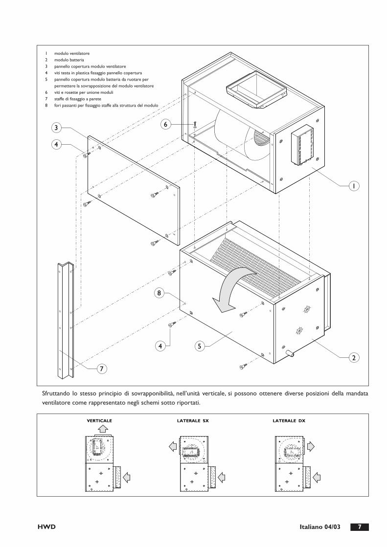
INSTALLAZIONE DELL’UNITÁ VERTICALELe due sezioni dell’unità, modulo ventilatore e modulo bat-teria, fornite per installazione orizzontale possono essereinstallate in verticale attraverso una semplice operazioneeseguibile in cantiere.L’operazione consiste nello spostare un pannello di coper-tura sia del modulo ventilatore che del modulo batteria(vedi figura sotto riportata). Una volta smontati i due pan-nelli si deve posizionare il modulo ventilatore sopra almodulo batteria e fissarli fra di loro mediante le appositevi-ti fornite in dotazione.
Fra i due moduli deve essere inserita la guarnizione adesivadi tenuta fornita in dotazione.Viene fornito a richiesta un accessorio staffe di fissaggioche permettono una più semplice installazione a parete deidue moduli già preassemblati, le staffe si fissano agli attacchifilettati M6 presenti sulla struttura (vedi figura paginaseguente).
HWD 7Italiano 04/03
2
3
4
8
54
7
1
6
1 modulo ventilatore2 modulo batteria3 pannello copertura modulo ventilatore4 viti testa in plastica fissaggio pannello copertura5 pannello copertura modulo batteria da ruotare per
permettere la sovrapposizione del modulo ventilatore 6 viti e rosette per unione moduli7 staffe di fissaggio a parete8 fori passanti per fissaggio staffe alla struttura del modulo
VERTICALE LATERALE SX LATERALE DX
Sfruttando lo stesso principio di sovrapponibilità, nell’unità verticale, si possono ottenere diverse posizioni della mandataventilatore come rappresentato negli schemi sotto riportati.

SPAZI FUNZIONALI
HWD8 Italiano 04/03
Min. 100 mm (*) Min. 400 mm
Nota: mantenere una inclinazione minima di 2 mm/m verso lo scarico condensa.
(*) Per smontaggio filtro inferiore - Min. 750 mm per smontaggio filtro laterale
AI
COLLEGAMENTI IDRAULICI
L’unità viene fornita con gli attacchi idraulici sul lato dx guardando lebocche di mandata aria. In caso di necessità gli attacchi si possonoportare sul lato sx ruotando la batteria con una operazione moltosemplice eseguibile in cantiere prima di installare la macchina.L’operazione prevede lo smontaggio del pannello ventilatore e dellavaschetta raccolta condensa per accedere alla batteria. Smontare quin-di la batteria dal basso, ruotarla di 180° sul piano orizzontale e rimon-tarla. Rimontare la vaschetta ed il pannello ventilatore. È possibile conla rotazione degli attacchi acqua spostare sullo stesso lato il quadroelettrico usufruendo delle forature già predisposte. La rotazione delquadro elettrico prevede la sistemazione del cablaggio del ventilatore.
COLLEGAMENTO TUBAZIONE ACQUAPrevedere il diametro delle tubazioni di collegamento idraulico dimen-sionato in modo adeguato al reale sviluppo delle tubazioni stesse ecomunque mai inferiore al diametro di attacco presente in macchina.
COLLEGAMENTO DELLO SCARICO DELLA CONDENSAOperazione molto importante da farsi con particolare cura daparte di personale specializzato. L’unità è provvista di bacinella scari-co condensa con attacco destro. Lo scarico previsto è di tipo natu-
rale. Il tubo consigliato è un tubo con diametro interno da 20 mmminimo: l’attacco per lo scarico ha un diametro esterno da 22 mm.
IMPORTANTE:lo scarico naturale può essere trasformato in forzatomediante l’utilizzo dell’accessorio pompa scarico condensa.Per la sequenza attenersi alle seguenti istruzioni: (vedi figura)1. Collegare il tubo di scarico della condensa allo scarico
della bacinella con una fascetta stringi tubo.2. Prevedere che il tubo di scarico mantenga una pendenza di
almeno 2 cm/m, senza presentare ostruzioni o strozzature.3. Prevedere un sifone che, eliminando la depressione provocata dal
ventilatore, impedisca l’aspirazione di gas dalla tubazione di scarico.4. Collegare lo scarico della condensa ad una rete di scari-
co pluviale. Non utilizzare scarichi di acque bianche onere onde evitare possibili aspirazioni di odori nel casodi evaporazione dell’acqua contenuta nel sifone.
5. Verificare a fine lavoro il regolare deflusso della conden-sa versando dell’acqua nella bacinella.
6. Se necessario prevedere un adeguato isolamento deltubo scarico condensa.
AI

COLLEGAMENTI ELETTRICI
HWD 9Italiano 04/03
B
E C
D
A
A Morsettiera alimentazione D Pressacavi RP1-4 Trimmer regolazione velocitàB Filtro rete E Condensatore ventilatoreC Scheda regolazione ventilatore FU1 Fusibile scheda
AI
PTH2 THERMOSTAT
3
1
5 6
BT
C$
2 3M
IN
MED
MAX
6 5 10987
IS3
IS4IS2
IS1
ST
7 0 4 6 5 8 9 3 2 1
4 7
N
N
QF
10
4
2
L
0
1
1198
A1U1L2
U3N4 A2
3
230V
ac1
PE L
OR
AN
GE
OR
AN
GE
WH
ITE
BRO
WN
BLAC
K
BRO
WN
BRO
WN
BLAC
K
BLU
E
C1
EV1
M1~
LAYOUT QUADRO ELETTRICO
SCHEMA ELETTRICO
Schema elettrico di principio, fare riferimento allo schema sul quadro elettrico dell’unità.
A1 Filtro antidisturbo ST Sensore di temperatura 1 A cura del cliente
A2 Controllore elettronico IS1 Interruttore acceso/spento 2 Uscita per comando estivo
BT Termostato ambiente IS2 Selettore estate/inverno 3 Uscita per comando invernale
C1 Condensatore di marcia ventilatore IS3 Selettore automatico/manuale
EV1 Ventilatore IS4 Selettore velocità ventilatore
QF Interruttore di protezione gruppo a carico del cliente

HWD10 Italiano 04/03
65
78
910
LN
12
39
85
64
07
STIS1
IS2
IS4
IS3
MAXMEDMIN
C
PTH
2
YV1
L1PE
QF2
N
HW
D 0
071-
0121
ELE
CT
RIC
AL
BOA
RD
65
78
910
LN
HO
T W
AT
ERH
EAT
EX
CA
NG
ER
MA
X L
OA
D F
OR
EXIT
N°5
=3A
230
V
YV
2
12
39
85
64
07
STIS1
IS2
IS4
IS3
MAXMEDMIN
C
PTH
2
YV1
QF2
PEN
L1
HW
D 0
071-
0121
ELE
CT
RIC
AL
BO
AR
D
65
78
910
LN
UV
W1
23
45
6
HW
D 0
071-
0121
ELE
CT
RIC
AL
BO
AR
D 0
071-
0121
�H
EAT
ER
�E
LEC
TR
ICA
L B
OA
RD
RD
PR
YV
1
70
46
58
93
21
MAXMEDMIN
IS3
IS1
QF2
QF4 Q
F1
°CST
IS2
IS4
PTH
2
PEL1
L2L3
N
65
78
910
LN
HEA
TER
KA1 R1
12
39
85
64
07
STIS1
IS2
IS4
IS3
MAXMEDMIN
C
PTH
2
YV1
L1PE
QF2
N
MA
X L
OA
D F
OR
EXIT
N°5
=3A
230
V
~
HW
D 0
071-
0121
ELE
CT
RIC
AL
BOA
RD
SCHEMI DI COLLEGAMENTO
BASE CON BATTERA AD ACQUA CALDA
CON BATTERIA ELETTRICA DI SERIE CON BATTERIA ELETTRICA GENERALE
PTH2 Termostato ambienteIS1 Interruttore on/offIS2 Selettore estate/invernoIS3 Selettore automatico/manualeIS4 Selettore velocita' ventilatore
ST Sensore di temperaturaKA1 Rele' ausiliario batteria resistenzePR Pulsante ripristino resistenze elttricheQF1 Interruttore di protezione gruppoQF2 Interruttore di protezione unita' interna
QF3 Interruttore di protezione batteria resistenzeR1 Batteria resistenzeRD Lampada di segnalazione allarmeYV1 Valvola batteria principaleYV2 Valvola batteria aggiuntiva acqua calda

DATI TECNICI GENERALI
HWD 11Italiano 04/03
Potenzialità frigorifera totale (1) kW 16,8 20,1 23,4 29,8Potenzialità frigorifera sensibile (1) kW 12,3 14,4 17,3 21,7Potenzialità termica (2) kW 16,3 19,6 23,0 29,8Potenza termica batteria aggiuntiva (3) kW 25,0 25,0 36,0 39,0
Grandezza 0071 0091 0101 0121
Attacchi idraulici batteria standard Gas 1”/1/4 1”/1/4 1”/1/2 1”/1/2Attacchi idraulici batteria aggiuntiva Gas 3/4” 3/4” 1” 1”
Peso kg 144,5 147,5 160 170
Pressione sonora (4) dB(A) 60 60 66 69
Alimentazione elettrica V-Ph-Hz 230/1/50
Dimensione (A) mm 1300 1300 1500 1500Dimensione (B) mm 990 990 1220 1220Dimensione (H) mm 510 510 625 625
Potenza assorbita kW 0,68 0,68 1,75 2,24Corrente assorbita alle condizioni nom. A 2,9 2,9 7,9 9,5Corrente assorbita alle condizioni max A 3,2 3,2 10,5 10,5
Perdite di carico batteria standard (1) kPa 24 22 12,3 12Perdite di carico batteria aggiuntiva (3) kPa 13 13 19 22
Numero giranti-diametro N°-mm 1-254 1-254 1-254 1-254Portata aria nominale m3/h 3200 3200 4400 5000Prevalenza utile (unità base con filtro) Pa 105 93 250 141
(1) Temperatura ambiente 27°C-50% U.R. ; temperatura acqua in/out 7/12°C (4) Rilevazione ad 1 m dal punto di uscita aria
(2) Temperatura ambiente 20°C - 50% U.R.,; temperatura acqua in/out 45°C Correzzione potenza termica/frigorifera:
(3) Temperatura ambiente 20°C - 50% U.R.,; temperatura acqua in/out 70/60°C velocità massima: 1,0 velocità media: 0,85 velocità minima: 0,76
AI

HWD12 Italiano 04/03
CURVE PRESTAZIONALI VENTILATORI
CURVE PRESTAZIONALI HWD 0071
CURVE PRESTAZIONALI HWD 0091
20
0
40
60
80
100
120
140
160
180
200
220
Pa
l/s
m3/h1750
486
2000
555
2250
625
2500
695
2750
764
3000
834
3250
903
3500
972
3750
1042
4000
1110
C B A D
Maxim
um
Medium
Minim
um
0
20
40
60
80
100
120
140
160
180
200
220
Pa
l/s
m3/h1750
111
2000
167
2250
222
2500
278
2750
333
3000
389
3250
444
3500
500
3750
556
4000
611
C B A D
Maxim
um
Medium
Minim
um
N.B.: Le prestazioni max. della curva “D” si riferiscono all’unità con minimo 1 metro di canale delle dimensioni della bocca del ventilatore
A

HWD 13Italiano 04/03
CURVE PRESTAZIONALI HWD 0101
CURVE PRESTAZIONALI HWD 0121
0
50
100
150
200
250
300
350
400
450
500
550
Pa
l/s
m3/h2500
635
3000
834
3500
972
4000
1110
4500
1250
5000
1389
5500
1228
C B A Maxim
um
Medium
Minim
um
D
0
50
100
150
200
250
300
350
400
450
500
550
Pa
l/s
m3/h2500
635
3000
834
3500
972
4000
1110
4500
1250
5000
1389
5500
1228
C B A
Medium
Maxim
um
Minim
um
D
N.B.: Le prestazioni max. della curva “D” si riferiscono all’unità con minimo 1 metro di canale delle dimensioni della bocca del ventilatore

HWD14 Italiano 04/03
PRESTAZIONI IN RAFFREDDAMENTO AI
15,1
10,1
13,4
9016
,911
,513
,889
20,0
13,6
13,8
8912
,89,
214
,690
14,2
10,4
15,0
8916
,912
,315
,189
10,2
8,2
16,0
9011
,39,
316
,389
13,4
11,0
16,4
897,
47,
217
,390
8,1
8,1
17,7
889,
69,
617
,788
6,0
6,0
18,9
826,
86,
819
,280
8,1
8,1
19,2
804,
94,
920
,474
5,5
5,5
20,7
736,
56,
520
,773
2583
19,4
2300
5,0
2898
24,4
2700
3430
34,2
3200
2186
13,7
2300
7,0
2438
17,1
2700
2888
24,0
3200
1753
8,8
2300
9,0
1936
10,7
2700
2298
15,1
3200
1275
4,6
2300
11,0
1399
5,5
2700
1653
7,7
3200
1041
3,0
2300
13,0
1177
3,9
2700
1391
5,4
3200
843
2,0
2300
15,0
952
2,5
2700
1126
3,5
3200
11,1
8,7
11,5
9012
,49,
911
,889
14,7
11,7
11,9
898,
97,
812
,790
9,9
8,8
13,0
8911
,710
,413
,189
6,8
6,8
14,0
887,
67,
614
,486
9,0
9,0
14,4
865,
45,
415
,878
6,1
6,1
16,1
777,
27,
216
,177
4,3
4,3
17,3
714,
94,
917
,570
5,8
5,8
17,5
703,
23,
218
,765
3,7
3,7
18,9
644,
34,
318
,964
13,0
9,4
12,4
9014
,610
,712
,889
17,3
12,7
12,9
8910
,88,
513
,790
12,0
9,7
14,0
8914
,211
,414
,189
8,4
7,5
14,9
909,
28,
615
,389
11,0
10,1
15,3
896,
36,
316
,584
7,1
7,1
16,9
828,
48,
416
,982
5,2
5,2
18,1
765,
85,
818
,375
6,9
6,9
18,4
754,
14,
119
,670
4,6
4,6
19,8
695,
45,
419
,869
17,2
10,8
14,4
9019
,312
,214
,890
22,9
14,4
14,9
8914
,89,
815
,790
16,5
11,2
16,1
8919
,613
,216
,189
12,1
8,8
17,0
9013
,410
,017
,489
15,9
11,8
17,5
899,
17,
818
,490
10,0
8,8
18,8
8911
,810
,418
,889
6,9
6,9
19,6
887,
87,
819
,986
9,2
9,2
20,0
865,
75,
721
,379
6,4
6,4
21,5
787,
67,
621
,678
19,4
11,3
15,5
9121
,812
,915
,990
25,8
15,2
16,0
9016
,910
,416
,890
18,9
11,8
17,2
9022
,414
,017
,389
14,1
9,4
18,1
9015
,610
,718
,589
18,6
12,6
18,6
8910
,88,
319
,690
11,9
9,4
20,0
8914
,111
,120
,189
8,4
7,5
20,7
909,
28,
621
,089
11,0
10,1
21,0
896,
56,
522
,185
7,4
7,4
22,4
838,
78,
722
,483
21,6
11,9
16,6
9124
,413
,517
,190
28,8
15,9
17,2
9019
,110
,917
,990
21,4
12,4
18,4
9025
,314
,718
,489
16,1
9,9
19,3
9017
,911
,319
,790
21,3
13,3
19,8
8912
,68,
820
,890
13,9
10,0
21,2
8916
,511
,821
,389
10,0
8,0
21,9
9011
,19,
122
,289
13,1
10,8
22,3
897,
57,
322
,990
8,3
8,3
23,2
889,
89,
823
,288
Twi
Qw
dPw
qa[˚C
][l/
h][k
Pa]
[m3 /h
]P
fP
fsTa
uU
R
[kW
][k
W]
[°C
][%
]P
fP
fsTa
uU
R
[kW
][k
W]
[°C
][%
]P
fP
fsTa
uU
R
[kW
][k
W]
[°C
][%
]P
fP
fsTa
uU
R
[kW
][k
W]
[°C
][%
]P
fP
fsTa
uU
R
[kW
][k
W]
[°C
][%
]P
fP
fsTa
uU
R
[kW
][k
W]
[°C
][%
]
Gra
ndez
za 0
071
TA
i 23°
C -
50%
UR
TA
i 25°
C -
50%
UR
TA
i 27°
C -
50%
UR
TA
i 29°
C -
50%
UR
TA
i 31°
C -
50%
UR
TA
i 33°
C -
50%
UR
17,9
11,8
11,1
9820
,113
,511
,598
23,6
15,9
11,6
9715
,310
,812
,598
17,1
12,3
12,9
9820
,114
,413
,097
12,5
9,7
14,0
9813
,811
,014
,497
16,2
13,0
14,4
979,
58,
515
,598
10,3
9,7
15,9
9712
,011
,415
,997
7,3
7,3
17,2
918,
28,
217
,689
9,7
9,7
17,6
885,
95,
919
,081
6,7
6,7
19,3
807,
97,
919
,479
3063
17,6
2300
5,0
3440
22,2
2700
4043
30,7
3200
2627
12,8
2300
7,0
2931
16,0
2700
3441
22,0
3200
2151
8,5
2300
9,0
2376
10,4
2700
2784
14,3
3200
1625
4,8
2300
11,0
1763
5,7
2700
2784
14,3
3200
1253
2,8
2300
13,0
1417
3,6
2700
1666
5,0
3200
1024
1,9
2300
15,0
1156
2,4
2700
1360
3,3
3200
13,2
10,2
9,6
9814
,811
,69,
997
17,3
13,7
10,0
9710
,79,
111
,098
11,9
10,4
11,3
9714
,012
,211
,497
8,1
8,0
12,4
989,
19,
112
,796
10,7
10,7
12,8
956,
66,
614
,386
7,4
7,4
14,7
848,
78,
714
,784
5,2
5,2
16,1
775,
95,
916
,475
6,9
6,9
16,4
753,
93,
917
,869
4,4
4,4
18,0
685,
25,
218
,068
15,5
11,0
10,3
9817
,412
,610
,798
20,4
14,8
10,8
9713
,010
,011
,798
14,5
11,3
12,1
9717
,013
,412
,297
10,3
8,9
13,1
9814
,511
,312
,197
13,3
11,9
13,6
977,
77,
714
,795
8,6
8,6
15,2
9210
,110
,115
,391
6,2
6,2
16,7
837,
07,
017
,082
8,3
8,3
17,0
824,
94,
918
,475
5,6
5,6
18,7
746,
56,
518
,773
20,4
12,6
11,9
9822
,914
,312
,498
26,9
16,9
12,5
9817
,711
,513
,498
19,8
13,1
13,8
9823
,315
,413
,997
14,8
10,4
14,9
9816
,411
,915
,398
19,3
14,0
15,4
9711
,69,
316
,498
12,6
10,5
16,8
9714
,712
,416
,997
8,5
8,2
17,8
989,
49,
418
,196
11,1
11,1
18,2
966,
96,
919
,688
7,8
7,8
20,0
869,
29,
220
,086
22,9
13,2
12,9
9825
,715
,113
,498
30,3
17,8
13,5
9820
,212
,214
,398
22,6
13,9
14,8
9826
,616
,414
,997
17,2
11,1
15,8
9819
,112
,616
,398
22,4
14,9
16,4
9713
,79,
917
,498
15,0
11,2
17,9
9817
,513
,218
,097
10,5
8,9
18,9
9811
,610
,219
,298
13,6
12,0
19,2
977,
97,
920
,195
9,0
9,0
20,6
9310
,510
,520
,692
25,4
13,8
13,9
9828
,715
,714
,598
33,7
18,5
14,6
989
22,7
12,8
15,3
9825
,514
,615
,898
29,9
17,2
16,0
9819
,611
,716
,898
21,8
13,3
17,3
9825
,615
,717
,497
16,0
10,5
18,5
9817
,511
,919
,098
20,4
14,0
19,1
9712
,59,
420
,098
13,8
10,8
20,3
9816
,212
,720
,397
9,6
8,6
21,1
9810
,59,
921
,498
12,3
11,6
21,5
97
Twi
Qw
dPw
qa[˚C
][l/
h][k
Pa]
[m3 /h
]P
fP
fsTa
uU
R
[kW
][k
W]
[°C
][%
]P
fP
fsTa
uU
R
[kW
][k
W]
[°C
][%
]P
fP
fsTa
uU
R
[kW
][k
W]
[°C
][%
]P
fP
fsTa
uU
R
[kW
][k
W]
[°C
][%
]P
fP
fsTa
uU
R
[kW
][k
W]
[°C
][%
]P
fP
fsTa
uU
R
[kW
][k
W]
[°C
][%
]
Gra
ndez
za 0
091
TA
i 23°
C -
50%
UR
TA
i 25°
C -
50%
UR
TA
i 27°
C -
50%
UR
TA
i 29°
C -
50%
UR
TA
i 31°
C -
50%
UR
TA
i 33°
C -
50%
UR
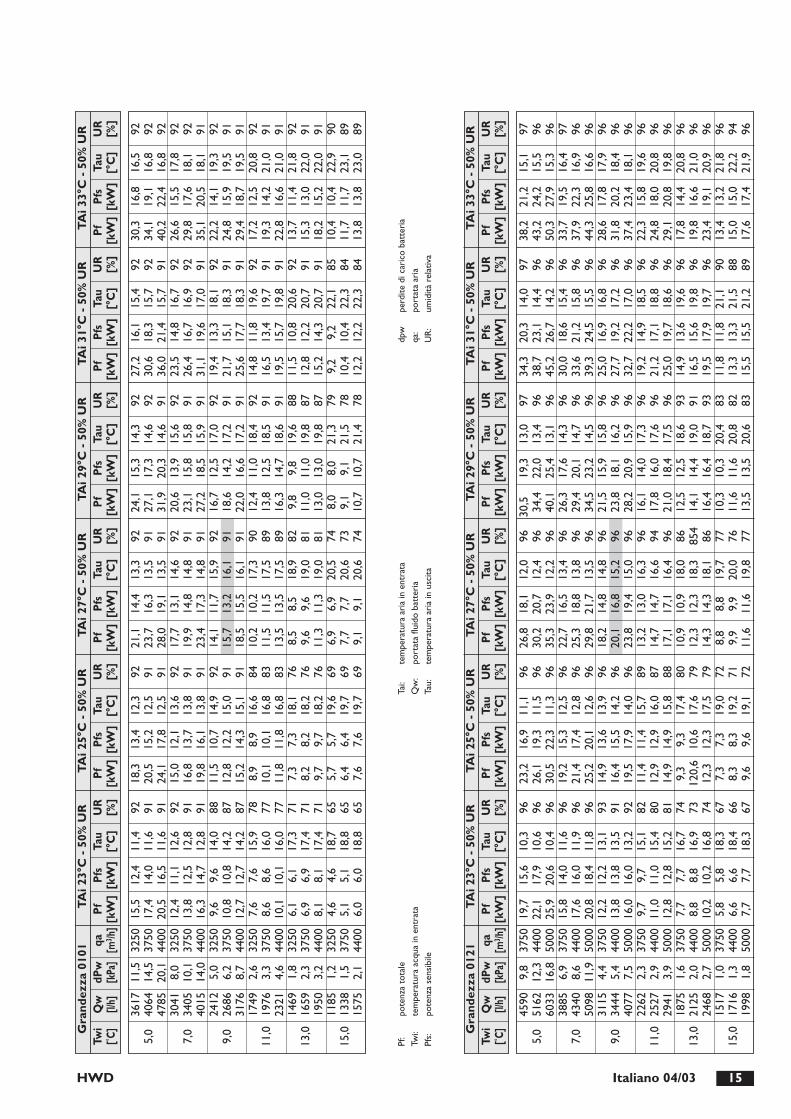
Pf:
pote
nza
tota
le
Twi:
tem
pera
tura
acq
ua in
ent
rata
Pfs:
pote
nza
sens
ibile
Tai:
tem
pera
tura
ari
a in
ent
rata
Qw
:po
rtat
a flu
ido
batt
eria
Ta
u:te
mpe
ratu
ra a
ria
in u
scita
dpw
perd
ite d
i car
ico
batt
eria
qa:
port
ata
aria
UR
:um
idità
rel
ativ
a
HWD 15Italiano 04/03
Pf:
pote
nza
tota
le
Twi:
tem
pera
tura
acq
ua in
ent
rata
Pfs:
pote
nza
sens
ibile
Tai:
tem
pera
tura
ari
a in
ent
rata
Qw
:po
rtat
a flu
ido
batt
eria
Ta
u:te
mpe
ratu
ra a
ria
in u
scita
dpw
perd
ite d
i car
ico
batt
eria
qa:
port
ata
aria
UR
:um
idità
rel
ativ
a
21,1
14,4
13,3
9223
,716
,313
,591
28,0
19,1
13,5
9117
,713
,114
,692
19,9
14,8
14,8
9123
,417
,314
,891
14,1
11,7
15,9
9215
,713
,216
,191
18,5
15,5
16,1
9110
,210
,217
,390
11,5
11,5
17,5
8913
,513
,517
,589
8,5
8,5
18,9
829,
69,
619
,081
11,3
11,3
19,0
816,
96,
920
,574
7,7
7,7
20,6
739,
19,
120
,674
3617
11,5
3250
5,0
4064
14,5
3750
4785
20,1
4400
3041
8,0
3250
7,0
3405
10,1
3750
4015
14,0
4400
2412
5,0
3250
9,0
2686
6,2
3750
3176
8,7
4400
1749
2,6
3250
11,0
1976
3,3
3750
2321
4,6
4400
1469
1,8
3250
13,0
1659
2,3
3750
1950
3,2
4400
1185
1,2
3250
15,0
1338
1,5
3750
1575
2,1
4400
15,5
12,4
11,4
9217
,414
,011
,691
20,5
16,5
11,6
9112
,411
,112
,692
13,8
12,5
12,8
9116
,314
,712
,891
9,6
9,6
14,0
8810
,810
,814
,287
12,7
12,7
14,2
877,
67,
615
,978
8,6
8,6
16,0
7710
,110
,116
,077
6,1
6,1
17,3
716,
96,
917
,471
8,1
8,1
17,4
714,
64,
618
,765
5,1
5,1
18,8
656,
06,
018
,865
18,3
13,4
12,3
9220
,515
,212
,591
24,1
17,8
12,5
9115
,012
,113
,692
16,8
13,7
13,8
9119
,816
,113
,891
11,5
10,7
14,9
9212
,812
,215
,091
15,2
14,3
15,1
918,
98,
916
,684
10,1
10,1
16,8
8311
,811
,816
,883
7,3
7,3
18,1
768,
28,
218
,276
9,7
9,7
18,2
765,
75,
719
,669
6,4
6,4
19,7
697,
67,
619
,769
24,1
15,3
14,3
9227
,117
,314
,692
31,9
20,3
14,6
9120
,613
,915
,692
23,1
15,8
15,8
9127
,218
,515
,991
16,7
12,5
17,0
9218
,614
,217
,291
22,0
16,6
17,2
9112
,411
,018
,492
13,8
12,5
18,5
9116
,314
,718
,691
9,8
9,8
19,6
8811
,011
,019
,887
13,0
13,0
19,8
878,
08,
021
,379
9,1
9,1
21,5
7810
,710
,721
,478
27,2
16,1
15,4
9230
,618
,315
,792
36,0
21,4
15,7
9123
,514
,816
,792
26,4
16,7
16,9
9231
,119
,617
,091
19,4
13,3
18,1
9221
,715
,118
,391
25,6
17,7
18,3
9114
,811
,819
,692
16,5
13,4
19,7
9119
,515
,719
,891
11,5
10,8
20,6
9212
,812
,220
,791
15,2
14,3
20,7
919,
29,
222
,185
10,4
10,4
22,3
8412
,212
,222
,384
30,3
16,8
16,5
9234
,119
,116
,892
40,2
22,4
16,8
9226
,615
,517
,892
29,8
17,6
18,1
9235
,120
,518
,191
22,2
14,1
19,3
9224
,815
,919
,591
29,4
18,7
19,5
9117
,212
,520
,892
19,3
14,2
21,0
9122
,816
,621
,091
13,7
11,4
21,8
9215
,313
,022
,091
18,2
15,2
22,0
9110
,410
,422
,990
11,7
11,7
23,1
8913
,813
,823
,089
Twi
Qw
dPw
qa[˚C
][l/
h][k
Pa]
[m3 /h
]P
fP
fsTa
uU
R
[kW
][k
W]
[°C
][%
]P
fP
fsTa
uU
R
[kW
][k
W]
[°C
][%
]P
fP
fsTa
uU
R
[kW
][k
W]
[°C
][%
]P
fP
fsTa
uU
R
[kW
][k
W]
[°C
][%
]P
fP
fsTa
uU
R
[kW
][k
W]
[°C
][%
]P
fP
fsTa
uU
R
[kW
][k
W]
[°C
][%
]
Gra
ndez
za 0
101
TA
i 23°
C -
50%
UR
TA
i 25°
C -
50%
UR
TA
i 27°
C -
50%
UR
TA
i 29°
C -
50%
UR
TA
i 31°
C -
50%
UR
TA
i 33°
C -
50%
UR
26,8
18,1
12,0
9630
,220
,712
,496
35,3
23,9
12,2
9622
,716
,513
,496
25,3
18,8
13,8
9629
,821
,713
,596
18,2
14,8
14,8
9620
,116
,815
,296
23,8
19,4
15,0
9613
,213
,016
,396
14,7
14,7
16,6
9417
,117
,116
,496
10,9
10,9
18,0
8612
,312
,318
,385
414
,314
,318
,186
8,8
8,8
19,7
779,
99,
920
,076
11,6
11,6
19,8
77
4590
9,8
3750
5,0
5162
12,3
4400
6033
16,8
5000
3885
6,9
3750
7,0
4340
8,6
4400
5098
11,9
5000
3115
4,4
3750
9,0
3444
5,4
4400
4077
7,5
5000
2262
2,3
3750
11,0
2527
2,9
4400
2941
3,9
5000
1875
1,6
3750
13,0
2125
2,0
4400
2468
2,7
5000
1517
1,0
3750
15,0
1716
1,3
4400
1998
1,8
5000
19,7
15,6
10,3
9622
,117
,910
,696
25,9
20,6
10,4
9615
,814
,011
,696
17,6
16,0
11,9
9620
,818
,411
,896
12,2
12,2
13,1
9313
,813
,813
,591
16,0
16,0
13,2
929,
79,
715
,182
11,0
11,0
15,4
8012
,812
,815
,281
7,7
7,7
16,7
748,
88,
816
,973
10,2
10,2
16,8
745,
85,
818
,367
6,6
6,6
18,4
667,
77,
718
,367
23,2
16,9
11,1
9626
,119
,311
,596
30,5
22,3
11,3
9619
,215
,312
,596
21,4
17,4
12,8
9625
,220
,112
,696
14,9
13,6
13,9
9616
,415
,514
,296
19,5
17,9
14,0
9611
,411
,415
,789
12,9
12,9
16,0
8714
,914
,915
,888
9,3
9,3
17,4
8012
0,6
10,6
17,6
7912
,312
,317
,579
7,3
7,3
19,0
728,
38,
319
,271
9,6
9,6
19,1
72
30,5
19,3
13,0
9734
,422
,013
,496
40,1
25,4
13,1
9626
,317
,614
,396
29,4
20,1
14,7
9634
,523
,214
,596
21,5
15,9
15,8
9623
,818
,116
,296
28,2
20,9
15,9
9616
,114
,017
,396
17,8
16,0
17,6
9621
,018
,417
,596
12,5
12,5
18,6
9314
,114
,419
,091
16,4
16,4
18,7
9310
,310
,320
,483
11,6
11,6
20,8
8213
,513
,520
,683
34,3
20,3
14,0
9738
,723
,114
,496
45,2
26,7
14,2
9630
,018
,615
,496
33,6
21,2
15,8
9639
,324
,515
,596
25,0
16,9
16,8
9627
,719
,217
,296
32,7
22,2
17,0
9619
,214
,918
,596
21,2
17,1
18,8
9625
,019
,718
,696
14,9
13,6
19,6
9616
,515
,619
,896
19,5
17,9
19,7
9611
,811
,821
,190
13,3
13,3
21,5
8815
,515
,521
,289
38,2
21,2
15,1
9743
,224
,215
,596
50,3
27,9
15,3
9633
,719
,516
,497
37,9
22,3
16,9
9644
,325
,816
,696
28,6
17,8
17,9
9631
,820
,218
,496
37,4
23,4
18,1
9622
,315
,819
,696
24,8
18,0
20,8
9629
,120
,819
,896
17,8
14,4
20,8
9619
,816
,621
,096
23,4
19,1
20,9
9613
,413
,221
,896
15,0
15,0
22,2
9417
,617
,421
,996
Twi
Qw
dPw
qa[˚C
][l/
h][k
Pa]
[m3 /h
]P
fP
fsTa
uU
R
[kW
][k
W]
[°C
][%
]P
fP
fsTa
uU
R
[kW
][k
W]
[°C
][%
]P
fP
fsTa
uU
R
[kW
][k
W]
[°C
][%
]P
fP
fsTa
uU
R
[kW
][k
W]
[°C
][%
]P
fP
fsTa
uU
R
[kW
][k
W]
[°C
][%
]P
fP
fsTa
uU
R
[kW
][k
W]
[°C
][%
]
Gra
ndez
za 0
121
TA
i 23°
C -
50%
UR
TA
i 25°
C -
50%
UR
TA
i 27°
C -
50%
UR
TA
i 29°
C -
50%
UR
TA
i 31°
C -
50%
UR
TA
i 33°
C -
50%
UR

HWD16 Italiano 04/03
PRESTAZIONI RISCALDAMENTO AI
2583 17,1 2300 12,8 30,5 11,8 31,3 10,8 32,2 9,9 33,0 8,9 33,8 7,9 34,640,0 2898 21,5 2700 14,5 29,9 13,4 30,8 12,3 31,7 11,1 32,5 10,0 33,4 8,9 34,2
3430 30,1 3200 17,2 29,9 15,9 30,8 14,6 31,7 13,3 32,6 11,9 33,4 10,6 34,32186 12,1 2300 15,0 33,3 14,1 34,3 13,1 35,1 12,1 36,0 11,2 36,9 10,2 37,7
45,0 2438 15,0 2700 17,0 32,6 15,9 33,6 14,8 34,5 13,7 35,4 12,6 36,3 11,5 37,22888 21,1 3200 20,2 32,7 18,9 33,6 17,6 34,6 16,3 35,5 15,0 36,4 13,7 37,31753 7,7 2300 17,0 35,8 16,0 36,8 15,1 37,7 14,1 38,7 13,2 39,6 12,3 40,5
50,0 1936 9,4 2700 19,1 34,9 18,1 36,0 17,0 36,9 15,9 37,9 14,9 38,9 13,8 39,82298 13,2 3200 22,8 35,0 21,5 36,0 20,2 37,0 19,0 38,0 17,7 39,0 16,4 39,91759 7,5 2300 22,0 42,3 21,0 43,3 20,1 44,3 19,1 45,2 18,2 46,2 17,2 47,2
60,0 1990 9,6 2700 24,9 41,2 23,8 42,3 22,7 43,3 21,6 44,3 20,6 45,3 19,5 46,32371 13,7 3200 29,6 41,4 28,3 42,4 27,0 43,4 25,8 44,5 24,5 45,5 23,2 46,42271 12,3 2300 27,8 49,7 26,8 50,8 25,8 51,8 24,8 52,8 23,8 53,8 22,8 54,7
70,0 2577 15,8 2700 31,5 48,5 30,4 49,6 29,3 50,6 28,1 51,7 27,0 52,7 25,9 53,73066 22,4 3200 37,5 48,7 36,2 49,7 34,8 50,8 33,5 51,8 32,2 52,8 30,8 53,82782 18,1 2300 33,5 57,1 32,5 58,2 31,5 59,3 30,5 60,3 29,5 61,3 28,5 62,3
80,0 3161 23,4 2700 38,1 55,7 36,9 56,8 35,8 57,9 34,6 58,9 33,5 60,0 32,3 61,03762 33,2 3200 45,3 55,9 44,0 57,0 42,6 58,1 41,2 59,1 39,9 60,2 38,5 61,2
Twi Qw dPw qa Pt Tau Pt Tau Pt Tau Pt Tau Pt Tau Pt Tau[˚C] [l/h] [kPa] [m3/h] [kW] [˚C] [kW] [˚C] [kW] [˚C] [kW] [˚C] [kW] [˚C] [kW] [˚C]
Grandezza 0071 Tai 14,0°C Tai 16,0°C Tai 18,0°C Tai 20,0°C Tai 22,0°C Tai 24,0°C
3063 15,5 2300 15,5 34,0 14,3 34,6 13,1 35,2 12,0 35,8 10,8 36,3 9,6 36,940,0 3440 16,9 2700 17,4 33,1 16,1 33,8 14,7 34,4 13,4 35,1 12,1 35,7 10,7 36,3
4043 27,0 3200 20,6 33,1 19,0 33,8 17,5 34,4 15,9 35,1 14,3 35,7 12,7 36,32627 11,3 2300 18,3 37,6 17,2 38,3 16,0 38,9 14,8 39,5 13,6 40,1 12,4 40,7
45,0 2931 14,0 2700 20,5 36,5 19,2 37,2 17,9 37,9 16,5 38,6 15,2 39,3 13,9 39,93441 19,3 3200 24,3 36,4 22,7 37,2 21,2 37,9 19,6 38,6 18,0 39,3 16,5 39,92151 7,5 2300 20,9 40,8 19,7 41,6 18,6 42,3 17,4 43,0 16,2 43,6 15,1 44,3
50,0 2376 9,1 2700 23,3 39,5 22,0 40,3 20,7 41,1 19,4 41,8 18,1 42,6 16,8 43,32784 12,5 3200 27,5 39,5 26,0 40,3 24,5 41,0 23,0 41,8 21,4 42,5 19,9 43,22160 7,3 2300 27,0 48,7 25,8 49,5 24,6 50,2 23,5 51,0 22,3 51,7 21,1 52,4
60,0 2412 9,1 2700 30,1 47,0 28,8 47,9 27,5 48,7 26,2 49,5 24,9 50,3 23,6 51,12857 12,8 3200 35,7 47,0 34,2 47,9 32,6 48,7 21,1 49,5 29,5 50,3 28,0 51,12761 11,7 2300 33,8 57,4 32,6 58,3 31,4 59,1 30,2 59,8 29,0 60,6 27,8 61,4
70,0 3094 14,8 2700 37,9 55,5 36,5 56,3 35,2 57,2 33,8 58,0 32,5 58,9 31,1 59,73673 20,8 3200 44,9 55,5 43,3 56,4 41,7 57,2 40,1 58,1 38,5 58,9 36,9 59,73361 17,1 2300 40,5 66,1 39,3 67,0 38,1 67,8 36,8 68,7 35,6 69,5 34,4 70,3
80,0 3777 21,6 2700 45,5 63,8 44,1 64,8 42,7 65,7 41,4 66,5 40,0 67,4 38,6 68,34481 30,4 3200 54,0 63,9 52,4 64,8 50,8 65,7 49,1 66,6 47,5 67,5 45,8 68,3
Twi Qw dPw qa Pt Tau Pt Tau Pt Tau Pt Tau Pt Tau Pt Tau[˚C] [l/h] [kPa] [m3/h] [kW] [˚C] [kW] [˚C] [kW] [˚C] [kW] [˚C] [kW] [˚C] [kW] [˚C]
Grandezza 0091 Tai 14,0°C Tai 16,0°C Tai 18,0°C Tai 20,0°C Tai 22,0°C Tai 24,0°C
3617 10,1 3250 18,3 30,7 16,9 31,5 15,5 32,4 14,1 33,2 12,7 34,0 11,3 34,740,0 4064 12,8 3750 20,5 30,2 18,9 31,0 17,3 31,9 15,8 32,8 14,2 33,6 12,6 64,4
4785 17,7 4400 24,3 30,4 22,5 31,2 20,6 32,1 18,7 32,9 16,9 33,7 15,0 34,53041 7,1 3250 21,5 33,5 20,1 34,4 18,7 35,3 17,3 36,2 15,9 37,0 14,6 37,9
45,0 3405 8,9 3750 24,0 32,9 22,4 33,9 20,9 34,8 19,4 35,7 17,8 36,6 16,3 37,44015 12,3 4400 28,5 33,2 26,7 34,1 24,8 35,0 23,0 35,9 21,2 36,8 19,3 37,62412 4,4 3250 24,1 36,0 22,8 36,9 21,5 37,9 20,1 38,8 18,8 39,7 17,5 40,6
50,0 2686 5,4 3750 26,9 35,2 25,4 36,2 23,9 37,2 22,4 38,2 21,0 39,1 19,5 40,13176 7,6 4400 32,0 35,5 30,2 36,5 28,5 37,5 26,7 38,4 24,9 39,4 23,1 40,32524 4,7 3250 31,5 42,7 30,2 43,7 28,8 44,7 27,4 45,6 26,1 46,6 24,7 47,5
60,0 2820 5,8 3750 35,2 41,8 33,7 42,8 32,2 43,8 30,6 44,8 29,1 45,8 27,6 46,83354 8,3 4400 41,9 42,2 40,1 43,2 38,3 44,2 36,5 45,2 34,7 46,1 32,8 47,13270 7,7 3250 40,0 50,4 38,6 51,4 37,2 52,4 35,7 53,4 34,3 54,4 32,9 55,3
70,0 3661 9,7 3750 44,8 49,3 43,2 50,3 41,6 51,4 40,0 52,4 38,4 53,4 36,8 54,44353 13,6 4400 53,2 49,8 51,4 50,8 49,5 51,8 47,6 52,8 45,7 53,8 43,8 54,84017 11,4 3250 48,4 58,0 46,9 59,1 45,5 60,1 44,0 61,1 42,5 62,1 41,1 63,1
80,0 4492 14,3 3750 54,2 56,7 52,5 57,8 50,9 58,9 49,3 59,9 47,6 60,9 46,0 61,95352 20,3 4400 64,5 57,3 62,5 58,4 60,6 59,4 58,6 60,5 56,7 61,5 54,7 62,5
Twi Qw dPw qa Pt Tau Pt Tau Pt Tau Pt Tau Pt Tau Pt Tau[˚C] [l/h] [kPa] [m3/h] [kW] [˚C] [kW] [˚C] [kW] [˚C] [kW] [˚C] [kW] [˚C] [kW] [˚C]
Grandezza 0101 Tai 14,0°C Tai 16,0°C Tai 18,0°C Tai 20,0°C Tai 22,0°C Tai 24,0°C
Pt: potenza termica Twi: temperatura acqua in entrataTai: temperatura aria in entrata
Qw: portata fluido batteria Tau: temperatura aria in uscitadpw perdite di carico batteria
qa: portata aria
BATTERIA PRINCIPALE

HWD 17Italiano 04/03
4590 8,6 3750 23,6 32,6 21,8 33,3 19,9 34,0 18,1 34,7 16,3 35,3 14,5 36,040,0 5162 10,9 4400 26,4 31,7 24,4 32,5 22,3 33,3 20,3 34,0 18,3 34,7 16,3 35,4
6033 14,8 5000 31,4 32,6 29,0 33,3 26,6 34,0 24,2 34,7 21,8 35,3 19,3 36,03885 6,1 3750 27,7 35,9 25,9 36,6 24,1 37,4 22,4 38,1 20,6 38,8 18,8 39,5
45,0 4340 7,6 4400 31,0 34,8 29,0 35,7 27,0 36,5 25,0 37,3 23,0 38,0 21,0 38,85098 10,5 5000 36,9 35,8 34,5 36,6 32,1 37,4 29,8 38,1 27,4 38,8 25,0 39,53115 3,9 3750 31,3 38,7 29,6 39,5 27,8 40,3 26,1 41,1 24,4 41,9 22,6 42,7
50,0 3444 4,7 4400 34,9 37,5 33,0 38,3 31,0 39,2 29,1 40,1 27,2 40,9 25,2 41,74077 6,6 5000 41,6 38,6 39,3 39,5 37,0 40,3 34,7 41,1 32,4 41,9 30,1 42,63273 4,2 3750 40,8 46,2 39,1 47,1 37,3 48,0 35,6 48,8 33,8 49,6 32,0 50,4
60,0 3660 5,2 4400 45,7 44,7 43,7 45,6 41,7 46,5 39,7 47,4 37,8 48,3 35,8 49,243,67 7,4 5000 54,5 46,2 52,1 47,1 49,8 48,0 47,4 48,8 45,1 49,6 42,7 50,44218 6,8 3750 51,6 54,7 49,7 55,6 47,9 56,4 46,1 57,3 44,2 58,2 42,4 59,0
70,0 4721 8,5 4400 57,8 52,9 55,8 53,8 53,7 54,7 51,6 55,6 49,6 56,5 47,5 57,45632 12,0 5000 68,9 54,8 66,5 55,7 64,0 56,5 61,5 57,4 59,1 58,2 56,6 59,15156 9,9 3750 62,1 63,0 60,3 64,0 58,4 64,9 56,5 65,8 54,6 66,7 52,7 67,5
80,0 5795 12,5 4400 69,8 60,9 67,7 61,9 65,6 62,9 63,5 63,8 61,4 64,8 59,3 65,76897 17,7 5000 83,1 63,2 80,6 64,1 78,1 65,0 75,6 65,9 73,1 66,8 70,6 67,7
Twi Qw dPw qa Pt Tau Pt Tau Pt Tau Pt Tau Pt Tau Pt Tau[˚C] [l/h] [kPa] [m3/h] [kW] [˚C] [kW] [˚C] [kW] [˚C] [kW] [˚C] [kW] [˚C] [kW] [˚C]
Grandezza 0121 Tai 14,0°C Tai 16,0°C Tai 18,0°C Tai 20,0°C Tai 22,0°C Tai 24,0°C
1094 3,8 2300 16,4 19,9 11,8 24,9 9,5 27,3 8,1 28,6 7,2 29,5 6,3 30,440,0 1217 4,7 2700 18,4 19,0 13,2 24,3 10,6 26,7 9,1 28,1 8,0 29,1 7,0 30,0
1366 5,9 3200 20,7 18,1 14,9 23,5 11,9 26,1 10,2 27,6 9,0 28,6 7,8 29,51534 7,3 2300 18,8 22,9 14,2 28,0 11,9 30,4 10,6 31,8 9,6 32,7 8,7 33,6
45,0 1722 9,3 2700 21,1 21,9 16,0 27,2 13,4 29,7 11,8 31,2 10,8 32,1 9,8 33,11929 11,6 3200 23,8 20,8 18,0 26,3 15,0 29,0 13,3 30,5 12,1 31,5 10,9 32,51949 11,7 2300 21,2 25,7 16,6 31,0 14,3 33,5 12,9 34,9 12,0 35,8 11,1 36,8
50,0 2177 14,6 2700 23,8 24,6 18,6 30,1 16,0 32,6 14,5 34,1 13,4 35,1 12,4 36,12454 18,5 3200 26,8 23,4 21,0 29,1 18,0 31,7 16,3 33,3 15,1 34,3 13,9 35,41237 4,6 2300 24,3 29,5 19,7 34,9 17,4 37,4 16,0 38,9 15,0 39,8 14,1 40,8
60,0 1380 5,7 2700 27,2 28,2 22,0 33,7 19,4 36,4 17,8 37,9 16,8 38,9 15,8 39,91549 7,2 3200 30,6 26,7 24,7 32,5 21,8 35,2 20,0 36,8 18,9 37,9 17,7 38,91667 8,2 2300 29,1 35,4 24,5 41,0 22,2 43,7 20,8 45,2 19,9 46,3 19,0 47,3
70,0 1868 10,3 2700 32,7 33,8 27,5 39,6 24,9 42,4 23,3 44,0 22,3 45,0 21,2 46,12097 13,0 3200 36,8 32,1 30,9 38,1 28,0 41,0 26,2 42,7 25,0 43,8 23,9 44,82102 12,8 2300 33,9 41,2 29,3 47,1 27,0 49,9 25,6 51,5 24,7 52,6 23,8 53,7
80,0 2355 16,0 2700 38,1 39,4 32,9 45,4 30,3 48,3 28,7 50,0 27,7 51,2 26,7 52,32651 20,3 3200 42,9 37,5 37,1 43,7 34,1 46,7 32,4 48,4 31,2 49,6 30,0 50,7
Twi Qw dPw qa Pt Tau Pt Tau Pt Tau Pt Tau Pt Tau Pt Tau[˚C] [l/h] [kPa] [m3/h] [kW] [˚C] [kW] [˚C] [kW] [˚C] [kW] [˚C] [kW] [˚C] [kW] [˚C]
Grandezza 0071 Tai 14,0°C Tai 16,0°C Tai 18,0°C Tai 20,0°C Tai 22,0°C Tai 24,0°C
1094 3,8 2300 16,4 19,9 11,8 24,9 9,5 27,3 8,1 28,6 7,2 29,5 6,3 30,440,0 1217 4,7 2700 18,4 19,0 13,2 24,3 10,6 26,7 9,1 28,1 8,0 29,1 7,0 30,0
1366 5,9 3200 20,7 18,1 14,9 23,5 11,9 26,1 10,2 27,6 9,0 28,6 7,8 29,51534 7,3 2300 18,8 22,9 14,2 28,0 11,9 30,4 10,6 31,8 9,6 32,7 8,7 33,6
45,0 1722 9,3 2700 21,1 21,9 16,0 27,2 13,4 29,7 11,8 31,2 10,8 32,1 9,8 33,11929 11,6 3200 23,8 20,8 18,0 26,3 15,0 29,0 13,3 30,5 12,1 31,5 10,9 32,51949 11,7 2300 21,2 25,7 16,6 31,0 14,3 33,5 12,9 34,9 12,0 35,8 11,1 36,8
50,0 2177 14,6 2700 23,8 24,6 18,6 30,1 16,0 32,6 14,5 34,1 13,4 35,1 12,4 36,12454 18,5 3200 26,8 23,4 21,0 29,1 18,0 31,7 16,3 33,3 15,1 34,3 13,9 35,41237 4,6 2300 24,3 29,5 19,7 34,9 17,4 37,4 16,0 38,9 15,0 39,8 14,1 40,8
60,0 1380 5,7 2700 27,2 28,2 22,0 33,7 19,4 36,4 17,8 37,9 16,8 38,9 15,8 39,91549 7,2 3200 30,6 26,7 24,7 32,5 21,8 35,2 20,0 36,8 18,9 37,9 17,7 38,91667 8,2 2300 29,1 35,4 24,5 41,0 22,2 43,7 20,8 45,2 19,9 46,3 19,0 47,3
70,0 1868 10,3 2700 32,7 33,8 27,5 39,6 24,9 42,4 23,3 44,0 22,3 45,0 21,2 46,12097 13,0 3200 36,8 32,1 30,9 38,1 28,0 41,0 26,2 42,7 25,0 43,8 23,9 44,82102 12,8 2300 33,9 41,2 29,3 47,1 27,0 49,9 25,6 51,5 24,7 52,6 23,8 53,7
80,0 2355 16,0 2700 38,1 39,4 32,9 45,4 30,3 48,3 28,7 50,0 27,7 51,2 26,7 52,32651 20,3 3200 42,9 37,5 37,1 43,7 34,1 46,7 32,4 48,4 31,2 49,6 30,0 510,7
Twi Qw dPw qa Pt Tau Pt Tau Pt Tau Pt Tau Pt Tau Pt Tau[˚C] [l/h] [kPa] [m3/h] [kW] [˚C] [kW] [˚C] [kW] [˚C] [kW] [˚C] [kW] [˚C] [kW] [˚C]
Grandezza 0091 Tai 14,0°C Tai 16,0°C Tai 18,0°C Tai 20,0°C Tai 22,0°C Tai 24,0°C
Pt: potenza termica Twi: temperatura acqua in entrataTai: temperatura aria in entrata
Qw: portata fluido batteria Tau: temperatura aria in uscitadpw perdite di carico batteria
qa: portata aria
BATTERIA AUSILIARIA
BATTERIA PRINCIPALE

HWD18 Italiano 04/03
Pt: potenza termica Twi: temperatura acqua in entrataTai: temperatura aria in entrata
Qw: portata fluido batteria Tau: temperatura aria in uscitadpw perdite di carico batteria
qa: portata aria
1627 5,4 3250 24,0 20,7 17,4 25,5 14,0 27,8 12,0 29,1 10,7 30,0 9,3 30,840,0 1794 6,6 3750 26,6 19,8 19,2 24,9 15,5 27,3 13,3 28,7 11,8 29,6 10,3 30,4
1991 8,1 4400 29,8 18,9 21,5 24,2 17,3 26,7 14,8 28,1 13,1 29,1 11,5 30,02263 10,4 3250 27,5 23,7 20,9 28,7 17,5 31,0 15,5 32,4 14,2 33,3 12,8 34,1
45,0 2511 12,8 3750 30,6 22,8 23,1 27,9 19,4 30,4 17,2 31,8 15,7 32,7 14,2 33,62795 15,9 4400 34,2 21,7 25,9 27,1 21,7 29,7 19,2 31,1 17,5 32,1 15,9 33,02857 16,3 3250 31,0 26,6 24,3 31,7 20,9 34,1 18,9 35,5 17,6 36,4 16,3 37,3
50,0 3166 20,1 3750 34,3 25,6 26,9 30,9 23,2 33,4 21,0 34,8 19,5 35,8 18,0 36,73537 25,0 4400 38,5 24,4 30,1 29,9 25,9 32,5 23,4 34,0 21,8 35,0 20,1 36,01825 6,5 3250 35,6 30,6 28,9 35,8 25,5 38,3 23,5 39,8 22,1 40,7 20,8 41,6
60,0 2016 7,9 3750 39,4 29,3 31,9 34,8 28,2 37,4 26,0 38,8 24,5 39,8 23,0 40,82245 9,8 4400 44,0 28,0 35,7 33,6 31,5 36,3 29,0 37,8 27,3 38,9 25,6 39,92446 11,5 3250 42,6 36,6 35,8 42,1 32,5 44,7 30,5 46,2 29,1 47,2 27,8 48,2
70,0 2708 14,0 3750 47,2 35,1 39,7 40,8 36,0 43,5 33,8 45,1 32,3 46,1 30,8 47,23024 17,5 4400 52,8 33,5 44,4 39,4 40,2 42,2 37,7 43,8 36,1 44,9 34,4 45,93067 17,7 3250 49,5 42,5 42,8 48,3 39,4 51,1 37,4 52,7 36,1 53,7 34,7 54,8
80,0 3401 21,7 3750 54,9 40,9 47,5 46,8 43,7 49,6 41,5 51,3 40,0 52,4 38,5 53,53809 27,3 4400 61,5 39,0 53,1 45,1 48,9 48,0 46,4 49,8 44,8 50,9 43,1 52,0
Twi Qw dPw qa Pt Tau Pt Tau Pt Tau Pt Tau Pt Tau Pt Tau[˚C] [l/h] [kPa] [m3/h] [kW] [˚C] [kW] [˚C] [kW] [˚C] [kW] [˚C] [kW] [˚C] [kW] [˚C]
Grandezza 0101 Tai 14,0°C Tai 16,0°C Tai 18,0°C Tai 20,0°C Tai 22,0°C Tai 24,0°C
1775 6,4 3750 26,4 19,7 19,1 24,8 15,4 27,2 13,2 28,6 11,7 29,5 10,2 30,340,0 1979 8,0 4400 29,6 18,8 21,3 24,1 17,2 26,6 14,7 28,0 13,0 29,0 11,4 29,9
2152 9,5 5000 32,3 18,0 23,2 23,5 18,7 26,1 16,0 27,6 14,2 28,6 12,4 29,62486 12,5 3750 30,3 22,6 22,9 27,8 19,2 30,2 17,0 31,7 15,6 32,6 14,1 33,5
45,0 2770 15,5 4400 33,9 21,5 25,6 27,0 21,5 29,5 19,0 31,0 17,4 32,0 15,7 32,93017 18,4 5000 37,0 20,7 28,0 26,3 23,5 28,9 20,7 30,5 18,9 31,5 17,1 32,53129 19,5 3750 34,1 25,4 26,7 30,7 23,0 33,2 20,8 34,7 19,3 35,6 17,8 36,6
50,0 3500 24,4 4400 38,1 24,2 29,9 29,7 25,7 32,4 23,2 33,9 21,6 34,9 19,9 35,93821 29,0 5000 41,7 23,3 32,6 29,0 28,1 31,7 25,4 33,3 23,5 34,5 21,7 35,31998 7,8 3750 39,1 29,1 31,7 34,6 28,0 37,2 25,7 38,7 24,3 39,6 22,8 40,6
60,0 2226 9,6 4400 43,7 27,7 35,4 33,4 31,2 36,1 28,7 37,7 27,1 38,7 25,4 39,72424 11,4 5000 47,7 26,6 38,63 32,4 34,0 35,2 31,3 36,8 29,5 37,9 27,6 39,02684 13,7 3750 46,8 34,8 39,4 40,5 35,7 43,3 33,5 44,9 32,0 45,9 30,5 46,9
70,0 2999 17,1 4400 52,4 33,2 44,1 39,1 39,9 41,9 37,4 43,6 35,7 44,7 34,1 45,73271 20,4 5000 57,2 31,9 48,1 38,0 43,5 40,9 40,8 42,6 39,0 43,7 37,2 44,83376 21,3 3750 54,5 40,6 47,1 46,5 43,4 49,4 41,2 51,0 39,7 52,1 38,2 53,2
80,0 3772 26,6 4400 61,0 38,7 52,7 44,8 48,5 47,8 46,0 49,5 44,4 50,6 42,7 51,84118 31,7 5000 66,6 37,2 57,5 43,5 530 46,5 50,3 48,3 48,4 49,4 46,6 50,6
Twi Qw dPw qa Pt Tau Pt Tau Pt Tau Pt Tau Pt Tau Pt Tau[˚C] [l/h] [kPa] [m3/h] [kW] [˚C] [kW] [˚C] [kW] [˚C] [kW] [˚C] [kW] [˚C] [kW] [˚C]
Grandezza 0121 Tai 14,0°C Tai 16,0°C Tai 18,0°C Tai 20,0°C Tai 22,0°C Tai 24,0°C
BATTERIA AUSILIARIA

HWD 19Italiano 04/03
Grandezza DimensioniA B H C C1 F F1
9 8
B 15 B 250 B
FF1 H C
1
A C
144 15 B 15 B
1
UNITÁ BASE CANALIZZABILE
7 2 3 6 5 4
1 modulo ventilatore (unità base) 5 plenum di aspirazione 10 modulo griglia mandata2 modulo batteria (unità base) 6 plenum aspirazione a due vie con serranda3 modulo filtro aria (unità base) 7 modulo batteria ad acqua per riscaldamento invernale4 modulo griglia aspirazione 9 plenum mandata
0071-0091 1300 495 510 1265 478 1204 3860101-0121 1500 610 625 1465 593 1404 501
ACCESSORIAI
D 15 B
A
E C
40 383
Grandezza Amm Bmm Cmm Dmm Emm0071-0091 1300 495 510 1267 4800101-0121 1500 610 625 1467 595
Tutti i modelli vengono forniti previsti per il fissaggio allaflangia di mandata dell’unità base, ad un altro modulo, oppu-re direttamente a canale. Prevedere sempre il montaggiodella guarnizione.
PLENUM ASPIRAZIONE A 2 VIE CON SERRANDAIl plenum di aspirazione a 2 vie con serranda permette dicollegare il canale di ripresa aria ambiente ed il canale diripresa aria esterna qualora l’impianto lo richieda.La regolazione avviene tramite una serranda manuale ditipo coniugato con possibilità di essere motorizzata previorimozione del volantino manuale (il comando motorizzato
non viene fornito). La sezione di passaggio del canale diripresa aria esterna è il 25% della sezione totale.Il montaggio è previsto direttamente accoppiato al modulobatteria.Nel caso di plenum di aspirazione a due vie montato, losmontaggio laterale del filtro è permesso togliendo il pan-nello fianco dal lato del volantino di regolazione serrande,oppure togliendo il pannello inferiore dello stesso modulo,per smontaggio inferiore.

HWD20 Italiano 04/03
BA30
C 150
DD
123 44 83
Grandezza Amm B1mm Dmm Emm Ø Att. Idr. Gas0071-0091 1300 250 510 180 3/4”0101-0121 1500 250 625 237,5 1”
MODULO BATTERIA AD ACQUA PER RISCAL-DAMENTO INVERNALEIl modulo batteria ad acqua per il riscaldamento invernaleviene impiegato negli impianti a 4 tubi qualora non vengautilizzato il riscaldamento ambiente tramite unità a pompadi calore. Può anche essere utilizzato come batteria di postriscaldamento estivo. Il montaggio del modulo batteria èprevisto per attacchi destro o sinistro.
La batteria è provvista di apposite valvole per lo sfiato del-l’aria o per l’eventuale scarico dell’acqua presente nellastessa qualora non venga utilizzata o per prevenire il gelo.Il modulo batteria può essere dotato di valvola di regola-zione on/off oppure modulante. La posizione di montaggioprevista è fra il modulo batteria principale ed il moduloventilatore sia nella configurazione macchina orizzontaleche verticale.
D 15 B
A
E C
Grandezza Amm Bmm Cmm Dmm Emm0071-0091 1300 495 510 1267 4800101-0121 1500 610 625 1467 595
PLENUM DI MANDATA (E ASPIRAZIONE)Il plenum di mandata e aspirazione è fornito qualora sia necessarioaspirare o mandare il flusso d’aria in basso. La parte maschio spor-gente 15 mm va accoppiata al modulo batteria nel caso di plenumdi aspirazione ed al modulo ventilatore o modulo resistenza elettri-ca nel caso di plenum di mandata. La modalità di montaggio almodulo batteria per il plenum aspirazione ed al modulo ventilatore
per il plenum di mandata sono le stesse per l’unione del modulobatteria e ventilatore. Nel caso di plenum di aspirazione montato, losmontaggio laterale del filtro è permesso togliendo il pannello fian-co dal lato attacchi del plenum, oppure togliendo il pannello interio-re dello stesso plenum, per smontaggio filtro inferiore.

HWD 21Italiano 04/03
4
3
C
B
A
2
1
5
3
C
GRIGLIE DI ASPIRAZIONE E MANDATAGli accessori griglie di aspirazione e mandata vengono for-niti per il montaggio diretto ai rispettivi plenum di aspira-zione e mandata, non è previsto il montaggio della griglia diaspirazione sul plenum a 2 vie con serranda. La griglia dimandata è dotata di alette orientabili in senso orizzontale everticale in modo indipendente. Gli accessori plenum diaspirazione e mandata abbinati alle rispettive griglie, nellaconfigurazione macchina verticale, consentono di ottenereuna soluzione di unità installabile in ambiente sulla tipologiadegli armadi, vedi disegno rappresentativo.
La composizione è possibile con le seguenti operazioni:- Sul modulo batteria spostare il pannello “A” nella posizio-
ne del filtro “B” e viceversa.- Spostare sul plenum di aspirazione il pannello “C” nella
posizione indicata e montare nel vano lasciato libero lagriglia di aspirazione.
- Spostare sul plenum di mandata il pannello “C” nella posi-zione indicata e montare nel vano lasciato libero la grigliadi mandata orientabile.
1 modulo ventilatore
2 modulo batteria
3 plenum di aspirazione/mandata
4 griglia di aspirazione
5 griglia di mandata
A pannello modulo batteria
B filtro
C pannello plenum aspirazione/mandata

RESA TERMICA BATTERIA AGGIUNTIVA
Twi: temperatura ingresso acqua Pt: potenzialità termica L’area tratteggiata si riferisce a condizioni di
Q: portata acqua Tau: temperatura uscita aria utilizzo di tipo industriale.
∅Pw: perdita di carico lato acqua Tai: temperatura ingresso aria Dati riferiti alle condizioni nominali.
Grandezza 0071-0091 Tai: -5°C Tai: 0°C Tai:10°C Tai:15°C Tai: 20°C Tai: 22°C
Grandezza 0101 Tai: -5°C Tai: 0°C Tai:10°C Tai:15°C Tai: 20°C Tai: 22°C
Grandezza 0121 Tai: -5°C Tai: 0°C Tai:10°C Tai:15°C Tai: 20°C Tai: 22°C
Twi Q ∅Pw Pt Tau Pt Tau Pt Tau Pt Tau Pt Tau Pt Tau°C l/h kPa kW °C kW °C kW °C kW °C kW °C kW °C
1370 5 29,8 22,9 27,6 25,8 23,3 31,7 20,9 34,6 18,7 37,4 17,9 38,760 1700 8 31,0 24,0 28,8 26,9 24,2 32,6 21,9 35,4 19,5 38,2 18,7 39,4
2200 13 32,3 25,2 30,0 28,0 25,2 33,5 22,8 36,3 20,3 39,0 19,4 40,01370 5 34,6 27,3 32,4 30,3 28,0 36,1 25,8 39,1 23,1 42,0 22,7 43,1
70 1700 8 36,0 28,7 33,8 31,5 29,2 37,3 26,9 40,1 24,0 42,9 23,6 44,02200 13 37,4 30,0 35,1 32,8 30,4 38,4 27,9 41,1 25,0 43,9 24,5 44,91370 5 39,3 31,7 37,2 34,8 32,8 40,6 30,6 43,6 28,2 46,3 27,4 47,6
80 1700 8 41,0 33,3 38,7 36,2 34,1 41,9 31,9 44,8 29,5 47,5 28,6 48,72200 13 44,3 36,4 40,2 37,6 35,5 43,2 33,1 45,9 30,6 48,7 29,8 49,8
Twi Q ∅Pw Pt Tau Pt Tau Pt Tau Pt Tau Pt Tau Pt Tau°C l/h kPa kW °C kW °C kW °C kW °C kW °C kW °C
1950 7 42,4 23,9 39,3 26,7 33,0 32,4 29,9 35,3 26,6 38,0 25,4 39,260 2450 11 44,3 35,4 41,0 27,8 34,4 33,4 31,2 36,1 27,7 38,8 26,5 39,9
3200 19 46,0 26,2 42,5 28,9 35,8 34,3 32,4 36,9 28,9 39,6 27,5 40,71950 7 49,2 28,4 46,0 31,3 39,8 37,0 36,7 39,9 33,5 42,7 32,2 43,9
70 2450 11 51,3 29,9 48,3 32,6 41,5 38,2 38,3 41,0 34,9 43,7 33,5 44,73200 19 53,2 31,1 49,8 33,9 43,1 39,3 39,7 42,0 36,0 44,5 34,9 45,61950 7 56,1 33,2 52,8 35,9 46,7 41,7 43,5 44,5 40,2 47,3 39,0 48,5
80 2450 11 58,2 34,6 55,0 37,4 48,6 43,0 45,3 45,8 42,1 48,6 40,7 49,63200 19 60,4 36,1 57,1 38,8 50,4 44,3 47,0 46,9 43,7 49,6 42,2 50,6
Twi Q ∅Pw Pt Tau Pt Tau Pt Tau Pt Tau Pt Tau Pt Tau°C l/h kPa kW °C kW °C kW °C kW °C kW °C kW °C
2050 8 45,5 22,2 42,2 25,2 35,5 31,2 32,0 34,1 28,6 37,1 27,3 38,360 2600 13 47,6 23,4 44,1 26,4 37,0 32,1 33,5 35,0 29,9 37,8 28,5 39,0
3400 22 49,5 24,6 45,9 27,4 38,6 33,0 34,9 35,8 31,2 38,6 29,7 39,72050 8 52,7 26,5 49,4 29,6 42,8 35,6 39,3 38,5 35,9 41,4 34,6 42,7
70 2600 13 55,1 27,9 51,6 30,9 44,7 36,7 41,2 39,6 37,5 42,4 36,1 43,63400 22 57,3 29,3 53,7 32,1 46,5 37,8 42,8 40,6 39,0 43,4 37,6 44,52050 8 60,0 30,9 56,7 33,9 50,1 39,9 46,6 42,8 43,3 45,9 41,9 47,0
80 2600 13 62,7 32,5 59,3 35,4 52,3 41,3 48,8 44,1 45,3 47,0 43,8 48,13400 22 65,1 33,9 61,5 36,8 54,3 42,5 50,7 45,3 47,0 48,0 45,5 49,2
AI
HWD22 Italiano 04/03
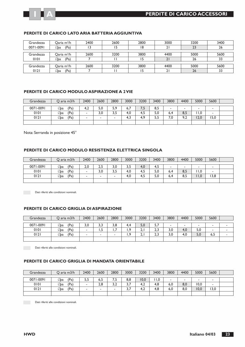
PERDITE DI CARICO ACCESSORI
HWD 23Italiano 04/03
Grandezza Qaria m3/h 2600 3200 3800 4400 5000 56000101 ∅pa (Pa) 7 11 15 21 26 33
Grandezza Qaria m3/h 2600 3200 3800 4400 5000 56000121 ∅pa (Pa) 7 11 15 21 26 33
Grandezza Q aria m3/h 2400 2600 2800 3000 3200 3400 3800 4400 5000 5600
PERDITE DI CARICO MODULO ASPIRAZIONE A 2 VIE
Nota: Serranda in posizione 45°
PERDITE DI CARICO LATO ARIA BATTERIA AGGIUNTIVA
PERDITE DI CARICO GRIGLIA DI ASPIRAZIONE
PERDITE DI CARICO MODULO RESISTENZA ELETTRICA SINGOLA
Grandezza Qaria m3/h 2400 2600 2800 3000 3200 34000071-0091 ∅pa (Pa) 13 15 18 21 23 26
Grandezza Q aria m3/h 2400 2600 2800 3000 3200 3400 3800 4400 5000 5600
Grandezza Q aria m3/h 2400 2600 2800 3000 3200 3400 3800 4400 5000 5600
Dati riferiti alle condizioni nominali.
0071-0091 ∅pa (Pa) 4,2 5,0 5,9 6,7 7,5 8,5 - - - -0101 ∅pa (Pa) - 3,0 3,5 4,0 4,5 5,0 6,4 8,5 11,0 -0121 ∅pa (Pa) - - - 4,3 4,9 5,5 7,0 9,2 12,0 15,0
0071-0091 ∅pa (Pa) 3,0 3,3 3,8 4,4 5,0 5,7 - - - - -0101 ∅pa (Pa) - 1,5 1,7 1,9 2,1 2,3 3,0 4,0 5,0 - -0121 ∅pa (Pa) - - - 1,9 2,1 2,3 3,0 4,0 5,0 6,5 -
0071-0091 ∅pa (Pa) 2,0 2,5 3,0 3,5 4,0 4,5 - - - -0101 ∅pa (Pa) - 3,0 3,5 4,0 4,5 5,0 6,4 8,5 11,0 -0121 ∅pa (Pa) - - - 4,0 4,5 5,0 6,4 8,5 11,0 13,8
Dati riferiti alle condizioni nominali.
PERDITE DI CARICO GRIGLIA DI MANDATA ORIENTABILE
Grandezza Q aria m3/h 2400 2600 2800 3000 3200 3400 3800 4400 5000 5600
Dati riferiti alle condizioni nominali.
0071-0091 ∅pa (Pa) 5,5 6,5 7,5 8,8 10,0 11,0 - - - -0101 ∅pa (Pa) - 2,8 3,2 3,7 4,2 4,8 6,0 8,0 10,0 -0121 ∅pa (Pa) - - - 3,7 4,2 4,8 6,0 8,0 10,0 13,0
AI

MESSA IN FUNZIONE
HWD24 Italiano 04/03
CONTROLLI PRELIMINARI1. Controllare il corretto posizionamento dell’unità inter-
na e il corretto allacciamento elettrico e frigorifero tral’unità esterna e quella interna;
2. Controllare che i valori di tensione e di frequenza rien-trino nei valori: 230V ± 10%.
3. Controllare che non ci siano allentamenti delle viti chefissano i conduttori ai componenti elettrici;
4. Verificare la connessione dello scarico condensa;5. Verificare che la mandata sia canalizzata6. Verificare la tenuta del circuito frigorifero mettendolo
in pressione.
AVVIAMENTOSe si è nei mesi estivi avviare l’unità esterna solo incondizio-namento, mentre nei mesi invernali solo in riscaldamento.
VERIFICHE DI PRIMA MESSA IN FUNZIONE1. Verificare che l’assorbimento dell’elettroventilatore sia infe-
riore alla corrente di spunto indicata in tabella a pag. 11;2. Verificare la corretta taratura delle velocità del ventila-
tore in funzione delle esigenze dell’impianto.
AI
DESCRIZIONE DEL COMANDO ELETTROMECCANICO
PTH2Il comando PTH2 funge da:1. selettore velocità ventilatore. Attraverso di esso si può
variare la velocità del ventilatore in minima, media emassima. Il valore di Set della sola velocità massima puòessere variata agendo sul potenziometro sito sulla sche-da elettronica a bordo macchina;
2. selettore Estate/Inverno/Ventilazione;3. termostato ambiente;4. seletore on/off5. selettore automatico/manuale

HWD 25Italiano 04/03
MODALITÁ DI TARATURA DEL VENTILATORE
Ogni modello di macchina viene fornito con le caratteristi-che di prestazione del ventilatore, velocità massima, mediae minima come indicato nei rispettivi diagrammi di ogniunità per le curve A, B e C (vedi pag. 12-13). Nella necessitàdi dover aumentare le prestazioni per vincere perdite dicarico aggiuntive e mantenere costante la portata d’arianominale, si ha a disposizione una prevalenza max residuariportata nella curva D. Un eventuale aumento della porta-ta max si ottiene agendo esclusivamente sul trimmer RP1posto sulla scheda di regolazione all’interno del quadroelettrico. L’accessibilità alla scheda è data smontando ilcoperchio del quadro elettrico. L’aumento della velocitàmax, (rotazione del trimmer RP1 in senso antiorario),porta all’aumento automatico delle velocità media e mini-ma in eguale entità. La diminuzione della velocità max(rotazione del trimmer RP1 in senso orario,) porta l’appiat-timento verso la velocità minima della velocità max stessa edella velocità media. Per comodità di scelta lo spostamento
tra la velocità max impostata (curva A) e la velocità maxdisponibile (curva D) è stato suddiviso in sette parti corri-spondenti alle curve indicate nei rispettivi diagrammi delleunità. L’incremento di tensione corrispondente ad ognicurva è dato dal rapporto:
V1= (230V - V) V1= incremento di tensione7 V = tensione velocità max
impostata (vedi tabella)
Quindi una volta individuata la curva corrispondente allaperdita di carico da vincere si ha anche la tensione allaquale tarare la velocità max attraverso il trimmer RP1 [ten-sione velocità max +(V1 x n° curva)]. Verificare sempre latensione al ventilatore una volta eseguita la nuova taratura.Di seguito diamo le tensioni di taratura delle velocità perogni macchina:
Modello HWD 0071 0091 0101 0121
Tensione alla velocità minima (V) 120 120 155 165Tensione alla velocità media (V) 135 135 165 190
Tensione alla velocità massima (V) 170 170 195 220
AI
Nota: Il metodo sopra descritto consente di ottenere una buona regolazione dell’impianto ma non precisa.È quindi buona norma eseguire un controllo sulla reale portata d’aria attraverso la misura della velocità d’aria nel canale.

HWD26 Italiano 04/03
IMPORTANTE:- Eseguire tutte le operazioni di manutenzione o pulizia
con la macchina non in tensione.- È consigliabile ad inizio stagione contattare Personale
qualificato per avvio stagionale.
Per garantire un corretto funzionamento nel tempo dell’u-nità, occorre eseguire alcune essenziali e semplici operazio-ni e controlli, che non necessitano dell’intervento di perso-nale specializzato e che possono essere eseguitidall’Utilizzatore finale:1. Controllo stato pulizia dei filtri aria;2. Controllo batteria;3. Controllo condizioni strutturali della macchina.
CONTROLLO STATO PULIZIA DEI FILTRI ARIAA seconda dell’ambiente in cui è installata l’unità interna,occorre periodicamente pulire i filtri aria. Il filtro può esse-re estratto dalla parte inferiore o dal lato attacchi dell’u-nità, operazione possibile anche in presenza di plenum aspi-razione o plenum aspirazione a 2 vie con serranda montati(vedi descrizione plenum).
Operazione di smontaggio e pulizia filtri1. Asportare la portina del lato interessato smontando le
viti che la fissano.2. Estrarre delicatamente il filtro aria dal basso del lato,
evitando di impolverare l’ambiente. (Il filtro è diviso in 2pezzi per facilitare l’estrazione).
3. Lavare il materassino filtrante con acqua tiepida e deter-gente comune, risciacquare e asciugare accuratamente.
MANUTENZIONE ORDINARIA
CONTROLLO BATTERIA1. Liberare la batteria da eventuali incrostazioni e sporco.2. Controllare che le alette in alluminio non siano piegate
e nel caso lo fossero “pettinare” con appositoattrezzoper ripristinare un corretto flusso dell’aria attraverso labatteria.
CONTROLLO CONDIZIONI STRUTTURALIDELLA MACCHINA1. Verificare lo stato di conservazione della macchina nel
suo complesso.2. Controllare che non ci siano ossidazioni in atto e, nel
caso ci fossero, trattare le parti con vernici antiruggine.3. Verificare il fissaggio della pannellatura esterna.4. Verificare lo stato del materiale isolante e fonoassor-
bente interno.5. Verificare che i fissaggi non siano origine di rumori e/o
vibrazioni inopportune6. Controllare il corretto scarico della condensa e che
non ci siano incrostazioni nella bacinella.7. Verificare che il cavo dell'alimentazione sia ben conser-
vato e non presenti screpolature e lacerazioni.
AIU

INFORMAZIONI UTILI
HWD 27Italiano 04/03
U I A
Per informazioni relative all’assistenza tecnica e al reperimento delle parti di ricambio potete contattare:
CLIMAVENETA S.P.A. UFFICIO POST VENDITA - SETTORE RESIDENZIALE
Via Duca d’Aosta 121 - 31031 Mignagola di Carbonera (TV) ITALIA
www.climaveneta.it – [email protected]
Numero Verde
800 019 190

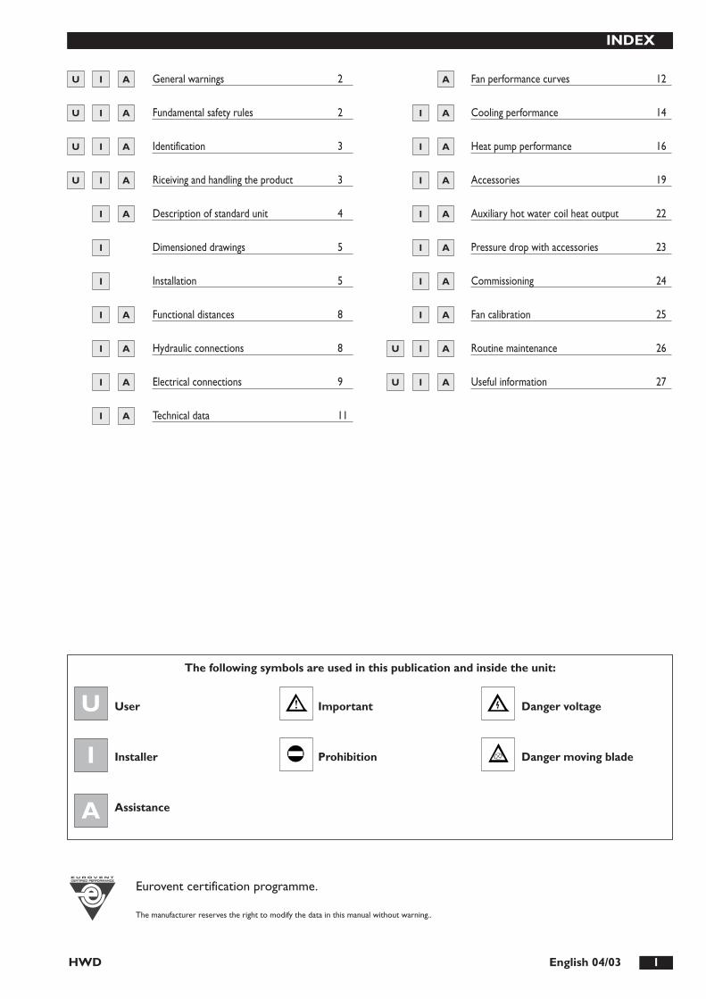
HWD 1English 04/03
INDEX
General warnings 2
Fundamental safety rules 2
Identification 3
Riceiving and handling the product 3
Description of standard unit 4
Dimensioned drawings 5
Installation 5
Functional distances 8
Hydraulic connections 8
Electrical connections 9
Technical data 11
Fan performance curves 12
Cooling performance 14
Heat pump performance 16
Accessories 19
Auxiliary hot water coil heat output 22
Pressure drop with accessories 23
Commissioning 24
Fan calibration 25
Routine maintenance 26
Useful information 27
I A
I A
I A
I
A
A
I
I
I
I A
I A
A
A
A
A
I
I
A
A
I A
A
I
AAIU
AIU
U
U
I
I
U I
AU I
I
A
I
U
The manufacturer reserves the right to modify the data in this manual without warning..
Eurovent certification programme.
The following symbols are used in this publication and inside the unit:
User
Installer
Assistance
Important
Prohibition
Danger voltage
Danger moving blade

HWD2 English 04/03
GENERAL WARNINGS
HWD terminals are the internal units of a ductedhydronic system. When used in combination withwater chillers, they form a cooling only system, whenused with reversible water chillers/heat pumps, theyform a cooling and heating system.Incorrect installation, regulation and maintenance,improper use or installation by unqualified personnelabsolves the manufacturer from all liability,whether contractual or otherwise, for personal inju-ries or property damage . Only those applicationsspecifically indicated in this list are allowed.Read this manual carefully. All work must be car-ried out by qualified personnel in conformity withcurrent legislation in the country concerned.The guarantee is invalidated if the above instruc-tions are not observed and if the unit is started upfor the first time without the presence of personnelauthorised by the Company (where specified in thesupply contract) who should draw up a “start-upreport”.
The documentation supplied with the unitmust be consigned to the owner who should keep itcarefully for future consultation.When the items are consigned by the transpor-ter, check that the packaging and the unit are unda-maged. If damage, missing components or consign-ment errors are noted, indicate this on the deliverynote. A formal complaint should be sent via fax orregistered post to the After Sales Service within eightdays from the date of receipt of the items.All the operations involved in handling, installing, star-ting up and testing the unit must be carried out byqualified personnel. Failure to observe this warningcould cause serious damage.
When using this unit, which requires electricity and water,a number of fundamental safety rules must be observed,namely:
The unit must not be used by children orwithout adult supervision.Do not touch the unit with bare feet or with wetor damp parts of the body.Do not carry out cleaning operations withoutdisconnecting the unit from the electricity supply byplacing the main switch of the electrical installationin the “off” position.Do not modify safety or regulation deviceswithout authorisation and instructions from themanufacturer.Do not pull, detach or twist the electrical cablescoming out of the unit, even when disconnectedfrom the mains electricity supply.Do not open doors or panels providing accessto the internal parts of the unit.Do not dispose of, abandon or leave within reachof children packaging materials (cardboard, staples,plastic bags, etc) as they may represent a hazard.
Respect safety distances between the unit andother equipment or structures. Guarantee suitablespace for access to the unit for maintenance and/orservice operations.The unit must be installed in a closed techni-cal room. The fan outlets must be protected withducts or grills preventing access to the impellers.Power supply: the cross section of the electricalcables must be adequate for the power of the unitand the power supply voltage must correspond withthe value indicated on the respective units. All unitsmust be earthed in conformity with current legisla-tion in the country concerned.Hydraulic connections should be carried out asindicated in the instructions to guarantee correctoperation of the unit.Handle the unit with the utmost care (see table onpage 3) and avoid damaging it.
FUNDAMENTAL SAFETY RULES
U AI
U AI

HWD 3English 04/03
Dimension A (mm) 550 550 550 550 550 550 550 550Dimension B (mm) 1455 1455 1455 1455 1655 1655 1655 1655Dimension C (mm) 595 680 595 680 710 795 710 795Net Weight (kg) 69,5 75 69,5 78 80 80 90 80Gross Weight (kg) 81 86 81 89 92,5 92 102,5 92
HWD hydronic terminals can be identified by the:
Packaging labelGiving the data identifying the product.
Rating plateGiving the technical and performance data of the unit.If this is lost, ask the After Sales Service for a replacement.
Tampering with or the removal or absence of ratingplates or other means enabling the unit to be iden-tified causes problems during installation and main-tenance.
IDENTIFICATION
MODEL:
VOLTAGE:
CODE:
De' Longhi S.p.a. - 31100 Treviso / ItaliaVia L.Seitz, 47 - tel. 04224131 fax 0422413659
RECEIVING AND HANDLING THE PRODUCT
HWD hydronic terminals are supplied accompanied with aplastic envelope fixed to the top of the unit containing:- instruction manual;- guarantee certificate;- CE declaration.
The unit should always be handled by qualified personnelusing equipment adequate for the weight of the hydronicterminal.
The instruction manual is an integral part of theunit and should thus be read and kept carefully.
Do not dispose of packaging materials in the envi-ronment or leave them within reach of children asthey may represent a hazard or a source of pollution.
During transport, the hydronic terminalsshould be handled with extreme care.
C
A
B
12
12
Grandezza 0071 0091 0101 0121FAN HEAT EX. FAN HEAT EX. FAN HEAT EX. FAN HEAT EX.
U AI
POTENZA FRIGORIFERA ------------------- kWPOTENZA TERMICA ------------------- kWTIPO REFRIGERANTE -------------------CARICA REFRIGERANTE ------------------- KgPRESSIONE MASSIMA ------------------- barALIMENTAZIONE ELETTRICA DI POTENZA ------------------- V---HzALIMENTAZIONE ELETTRICA AUSILIARI ------------------- V---HzPOTENZA ELETTRICA MAX. ASSORBITA ------------------- kWCORRENTE MAX. ASSORBITA ------------------- ACORRENTE DI SPUNTO ------------------- ASCHEMA ELETTRICO ------------------- N°PESO IN FUNZIONAMENTO ------------------- KgANNO DI FABBRICAZIONE -------------------
COOLING CAPACITYHEATING CAPACITY TYPE OF REFRIGERANTREFRIGERANT CONTENTMAXIMUM PRESSURE MAIN ELECTRICAL POWER SUPPLY AUXILIARY ELECTRICAL POWER SUPPLY MAX. POWER INPUTMAX. ABSORBED CURRENT START-UP CURRENT ELECTRICAL WIRING DIAGRAM OPERATING WEIGHT YEAR OF FABRICATION
U AI
BAR CODEA

HWD4 English 04/03
DESCRIZIONE UNITÁ STANDARD
HWD units are designed for horizontal or verticalflush or in-view mounting.In combination with the accessories available, they can beused to create high specification installations for air distribu-tion and environmental temperature and humidity control.
STRUCTUREMade from hot-galvanised cataphoretic coatedsteel complete with couplings for connection toducting and gravity condensate drain pan.Internal thermal and acoustic insulation in self-extinguishingclosed cell expanded polyethylene. Removable regenerablefilter in self-extinguishing acrylic material. Insulating gasketfor connection to ducting.
HEAT EXCHANGE COILWith copper tubes and high exchange surface area alumi-nium fins.
FANElectric centrifugal fan with electronic speed regulation.Statically and dynamically balanced impeller. High workinghead.
ELECTRICAL PANELPower and control electrical switchboard constructed inaccordance with IEC 204-1/EN60204-1, complete withregulator and terminal board for connection to power sup-ply room control panel PRH, PSH, PTH1 (optional).
ACCESSORIES- Two way intake plenum with damper- Hot water heating coil module with right or left connec-
tions- discharge and intake plenum with orientable outlets- Intake grill- Adjustable discharge grill- PTH2 room thermostat, on/off, summer/winter, room
thermostat, three fan speed selector, auxiliary controls.- Ceiling fixing brackets, nuts and washers.- Additional condensate drain pan.
AI
7
7
8
231
1
39
9
3
5
4
40
36
35
3042
38
41
37
34
34 32
6
33
1 Pipe connection side cover panel2 Left side cover panel3 Long cover panel (upper)4 Short cover panel (lower)5 Condensate drain pan6 Finned coil7 Air filter8 Filter side cover panel
9 Filter lower side cover panel30 Right side cover panel31 Left side cover panel32 Long cover panel (lower)33 Short cover panel (upper)34 Fan frame35 Electric switchboard36 Electric switchboard structure
37 Electric switchboard cover38 Fan start capacitor39 Radio interference suppresser40 Terminal41 Electronical board42 Centrifugal fan

HWD 5English 04/03
Models DimensionsA B H D F F1 G R R1 R2 R3 S V V1 V2 V3
20 B 129
V3
V1
=V
=V
2
GF1
R3
R2
G
1
8 7
6
R R1
S
48
30
F48
2
A 80
Ø 2
2
35
H
3
D
4 5
DISEGNI DIMENSIONALI
1 ductable flange and fans
2 water in (0071-0091 1”1/4) (0101-0121 1”1/2)
3 water in (0071-0091 1”1/4) (0101-0121 1”1/2)
4 air filter bottom access
5 air filter side access
6 air filter (no. 2 modules)
7 condensate drain
8 electrical switchboard
0071-0091 1300 990 510 1139 1204 386 62 51 230 208 147 395 340 298 174 380101-0121 1500 1220 625 1369 1404 477 74 36 295 264 158 472 340 298 230 95
I
INSTALLAZIONE
IMPORTANT WARNINGSBefore proceeding with installation, observe the followingwarnings scrupulously:- read this manual carefully;- carry out all work in accordance with legislation in force
in the country concerned;- respect safety distances between the unit and other equip-
ment or structures. Guarantee adequate space for accessto the unit for maintenance and/or service operations;
- power supply: the cross section of the electrical cablesmust be adequate for the power of the unit and thepower supply voltage must correspond with the valueindicated on the respective units;
- all units must be earthed in conformity with legislation inforce in the country concerned;
- the guarantee is invalidated if the above instructions arenot respected and if the unit is started up for the firsttime without the presence of personnel authorised bythe Company (where specified in the supply contract)who should draw up a commissioning report;
- handle the unit with the utmost care to avoid damage;- the documentation supplied with the unit must be consi-
gned to the owner who should keep it carefully for futuremaintenance or assistance.
CHECKING THE UNIT FOR DAMAGEWhen the items are consigned by the transporter, checkthat the packaging and the unit are undamaged. If damage ormissing components are noted, indicate this on the deliverynote. A formal complaint should be sent via fax or registe-red post to the After Sales Department within eight days.
CHOICE OF INSTALLATION SITEBefore installing the unit, agree the site where it will beinstalled with the customer, taking the following points intoconsideration:- check that the fixing points are adequate to support the
weight of the unit;- pay scrupulous respect to safety distances between the
unit and other equipment or structures (see FunctionalDistances page 8);
- Install the unit with a minimum slope of 2 mm/m to gua-rantee drainage of condensate.
INSTALLING THE UNITBefore handling the unit, check the capacity of the lift equip-ment used, respecting the instructions on the packaging.To move the unit horizontally, make appropriate use of lifttrucks or similar.
I

HWD6 English 04/03
HORIZONTAL UNIT INSTALLATION The unit is supplied in two separate sections, a fan moduleand a heat exchanger module.The modules are designed for horizontal mounting afterbeing joined together using the screws supplied. To access the screws fixing the two modules, remove oneof the fan cover panels (see figure below) by unscrewingthe four plastic-headed screws fixing it to the structure.
Insert the adhesive gasket supplied between the twomodules.A bracket mounting kit simplifying installation of the twomodules is available on request. The brackets are fixed tothe M6 threaded holes on the structure (see figure below).
7
2
1
4
5
36
1 fan module2 heat exchanger module3 cover panel4 cover panel plastic-headed fixing screws5 washers and screws for joining modules6 ceiling mounting brackets7 holes for fixing the brackets to the module structure.
VERTICAL UNIT INSTALLATION The same two sections of the unit (fan and heat exchangemodules) as supplied for horizontal installation can also beinstalled vertically following a simple operation to beperformed on site.This consists in moving one cover panel of both the fanand heat exchanger modules (see figure below). Once thetwo panels have been removed, position the fan module ontop of the heat exchanger module and join them togetherusing the screws supplied.
Insert the adhesive gasket supplied between the twomodules.A bracket mounting kit simplifying wall-mounting of thetwo pre-assembled modules is available on request. Thebrackets are fixed to the M6 threaded pins on the structu-re (see figure on next page).

HWD 7English 04/03
2
3
4
8
54
7
1
6
1 fan module2 heat exchanger module3 fan module cover panel4 cover panel plastic-headed fixing screws5 heat exchanger cover panel to be rotated to enable
top-mounting of the fan module 6 washers and screws for joining modules7 wall fixing brackets8 holes for fixing the brackets to the module structure
VERTICAL LEFT SIDE RIGHT SIDE
Exploiting the possibility of mounting one module on top of the other, in the vertical unit, various fan outlet positions can beobtained as shown in the diagrams below.

FUNCTIONAL DISTANCES
HWD8 English 04/03
Min. 100 mm (*) Min. 400 mm
Note: maintain a minimum slope of 2 mm/m towards the condensate drain.
(*) To remove filter downwards - 750 mm minimum for sideways removal of filter
AI
HYDRAULIC CONNECTIONS
The unit is supplied with the hydraulic connections on theright looking at the air outlets. If necessary, the connectionscan be brought to the left side by rotating the coil. This ope-ration can be carried out on site before installing the unit. Remove the fan panel and the condensate drain pan toaccess the coil. Remove the coil from the bottom, rotate ithorizontally through 180˚ and remount. Replace the drainpan and fan panel. After rotating the water connections, theelectrical switchboard can also be moved to the same sideby using the holes provided. When the electrical switch-board is rotated, the fan cabling must be re-arranged.
WATER PIPE CONNECTIONMake sure the diameter of the water pipes is adequate forthe actual length of the piping and in any case not less thanthe diameter of the connection on the unit.
CONDENSATE DRAIN CONNECTIONThis operation must be carried out with particular care.The unit is fitted with a gravity condensate drain pipe withright connection.
You are recommended to use a hose with a minimuminternal diameter of 20 mm: the drain connection has anexternal diameter of 22 mm.
IMPORTANTThe gravity drainage can be converted into forced drainageby using the condensate drain pump accessory.For the sequence, follow the instructions below (see figure).1. Connect the condensate drain pipe to the pan outlet
using a hose clamp.2. Make sure the drain pipe has a slope of at least 2 cm/m
without obstructions or bottlenecks.3. Fit a siphon. By eliminating the vacuum caused by the
fan, this prevents air being sucked up by the drain pipe.4. Connect the condensate drain pipe to a rainwater drai-
nage system. Do not connect to the sewage system asodours may be sucked up if the water in the siphonevaporates.
5. After connecting, check correct drainage of the con-densate by pouring water into the pan.
6. If necessary, insulate the condensate drainpipe adequately.
AI

POWER CONNECTIONS
HWD 9English 04/03
B
E C
D
A
A Power supply terminal board D Cable grips RP1 Speed regulation trimmerB Noise filter E Fan capacitorC Fan regulation board FU1 Board fuse
AI
PTH2 THERMOSTAT
3
1
5 6
BT
C$
2 3M
IN
MED
MAX
6 5 10987
IS3
IS4IS2
IS1
ST
7 0 4 6 5 8 9 3 2 1
4 7
N
N
QF
10
4
2
L
0
1
1198
A1U1L2
U3N4 A2
3
230V
ac1
PE L
OR
AN
GE
OR
AN
GE
WH
ITE
BRO
WN
BLAC
K
BRO
WN
BRO
WN
BLAC
K
BLU
E
C1
EV1
M1~
LAYOUT OF ELECTRICAL SWITCHBOARD
ELECTRICAL WIRING DIAGRAM
Basic wiring diagram, refer to the diagram on the electric control panel of the unit
A1 Radio interference suppresserA2 Electronic controllerBT Room thermostatC1 Compressor start capacitorEV1 FanQF Protection switchST Temperature sensor
IS1 ON/OFF switchIS2 Summer/winter selector IS3 Automatic/manual selectorIS4 Fan speed selector
1 Installer’s responsibility2 Output for chilling signal 3 Output for heating signal
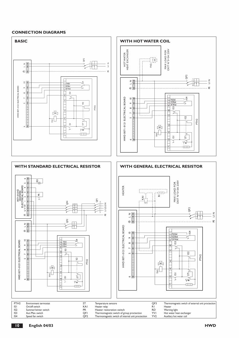
HWD10 English 04/03
65
78
910
LN
12
39
85
64
07
STIS1
IS2
IS4
IS3
MAXMEDMIN
C
PTH
2
YV1
L1PE
QF2
N
HW
D 0
071-
0121
ELE
CT
RIC
AL
BOA
RD
65
78
910
LN
HO
T W
AT
ERH
EAT
EX
CA
NG
ER
MA
X L
OA
D F
OR
EXIT
N°5
=3A
230
V
YV
2
12
39
85
64
07
STIS1
IS2
IS4
IS3
MAXMEDMIN
C
PTH
2
YV1
QF2
PEN
L1
HW
D 0
071-
0121
ELE
CT
RIC
AL
BO
AR
D
65
78
910
LN
UV
W1
23
45
6
HW
D 0
071-
0121
ELE
CT
RIC
AL
BO
AR
D 0
071-
0121
�H
EAT
ER
�E
LEC
TR
ICA
L B
OA
RD
RD
PR
YV
1
70
46
58
93
21
MAXMEDMIN
IS3
IS1
QF2
QF4 Q
F1
°CST
IS2
IS4
PTH
2
PEL1
L2L3
N
65
78
910
LN
HEA
TER
KA1 R1
12
39
85
64
07
STIS1
IS2
IS4
IS3
MAXMEDMIN
C
PTH
2
YV1
L1PE
QF2
N
MA
X L
OA
D F
OR
EXIT
N°5
=3A
230
V
~
HW
D 0
071-
0121
ELE
CT
RIC
AL
BOA
RD
CONNECTION DIAGRAMS
BASIC WITH HOT WATER COIL
WITH STANDARD ELECTRICAL RESISTOR WITH GENERAL ELECTRICAL RESISTOR
PTH2 Environment termostatIS1 On/off switchIS2 Summer/winter switchIS3 Aut./Man. switchIS4 Speed fan switch
ST Temperature sensoreKA1 Heater relayPR Heater restoration switchQF1 Thermomagnetic switch of group proctectionQF2 Thermomagnetic switch of internal unit proctection
QF3 Thermomagnetic switch of external unit proctectionR1 HeaterRD Warning lightYV1 Hot water heat exchangerYV2 Auxiliary hot water coil

TECHNICAL DATA
HWD 11English 04/03
AI
Total cooling capacity (1) kW 16,8 20,1 23,4 29,8Sensitive cooling capacity (1) kW 12,3 14,4 17,3 21,7Heat output (2) kW 16,3 19,6 23,0 29,8Heating capacity supplementary coil (3) kW 25,0 25,0 36,0 39,0
Model 0071 0091 0101 0121
Hydraulic connections standard coil gas Gas 1”/1/4 1”/1/4 1”/1/2 1”/1/2Hydraulic connections supplementary coil gas Gas 3/4” 3/4” 1” 1”
Weight kg 121 124 145 149
Sound pressure level (4) dB(A) 60 60 66 69
Electrical power supply V-Ph-Hz 230/1/50
Dimension (A) mm 1300 1300 1500 1500Dimension (B) mm 990 990 1220 1220Dimension (H) mm 510 510 625 625
Power input kW 0,68 0,68 1,75 2,24Absorbed current at nominal conditions A 2,9 2,9 7,9 9,5Current absorbed at maximum conditions A 3,2 3,2 10,5 10,5
Pressure drop standard coil (1) kPa 24 22 12,3 12Pressure drop auxiliary coil (3) kPa 13 13 19 22
Number impellers/diameter N°-mm 1-254 1-254 1-254 1-254Nominal air flow m3/h 3200 3200 4400 5000Useful head (basic unit with filter) Pa 105 93 250 141
(1) Room temperature 27°C-50% R.H.; water in/out temperature 7/12°C (4) Measured at 1 m from air discharge point
(2) Room temperature 20°C - 50% R.H.; water in/out temperature 45°C Heating/cooling capacity correction
(3) Room temperature 20°C - 50% R.H.; water in/out temperature 70/60°C Maximum speed: 1.0 Medium speed: 0.85 Minimum speed: 0.76

HWD12 English 04/03
FAN PERFORMANCE CURVES
PERFORMANCE CURVES HWD 0071
PERFORMANCE CURVES HWD 0091
20
0
40
60
80
100
120
140
160
180
200
220
Pa
l/s
m3/h1750
486
2000
555
2250
625
2500
695
2750
764
3000
834
3250
903
3500
972
3750
1042
4000
1110
C B A D
Maxim
um
Medium
Minim
um
0
20
40
60
80
100
120
140
160
180
200
220
Pa
l/s
m3/h1750
111
2000
167
2250
222
2500
278
2750
333
3000
389
3250
444
3500
500
3750
556
4000
611
C B A D
Maxim
um
Medium
Minim
um
N.B.: The max. performance of curve “D” refers to the unit with the minimum length of 1 m of ducting with the same dimensions as the fan outlet.
A
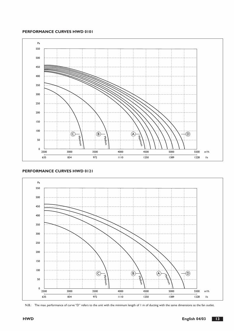
HWD 13English 04/03
PERFORMANCE CURVES HWD 0101
PERFORMANCE CURVES HWD 0121
0
50
100
150
200
250
300
350
400
450
500
550
Pa
l/s
m3/h2500
635
3000
834
3500
972
4000
1110
4500
1250
5000
1389
5500
1228
C B A Maxim
um
Medium
Minim
um
D
0
50
100
150
200
250
300
350
400
450
500
550
Pa
l/s
m3/h2500
635
3000
834
3500
972
4000
1110
4500
1250
5000
1389
5500
1228
C B A
Medium
Maxim
um
Minim
um
D
N.B.: The max. performance of curve “D” refers to the unit with the minimum length of 1 m of ducting with the same dimensions as the fan outlet.

HWD14 English 04/03
COOLING PERFORMANCE AI
15,1
10,1
13,4
9016
,911
,513
,889
20,0
13,6
13,8
8912
,89,
214
,690
14,2
10,4
15,0
8916
,912
,315
,189
10,2
8,2
16,0
9011
,39,
316
,389
13,4
11,0
16,4
897,
47,
217
,390
8,1
8,1
17,7
889,
69,
617
,788
6,0
6,0
18,9
826,
86,
819
,280
8,1
8,1
19,2
804,
94,
920
,474
5,5
5,5
20,7
736,
56,
520
,773
2583
19,4
2300
5,0
2898
24,4
2700
3430
34,2
3200
2186
13,7
2300
7,0
2438
17,1
2700
2888
24,0
3200
1753
8,8
2300
9,0
1936
10,7
2700
2298
15,1
3200
1275
4,6
2300
11,0
1399
5,5
2700
1653
7,7
3200
1041
3,0
2300
13,0
1177
3,9
2700
1391
5,4
3200
843
2,0
2300
15,0
952
2,5
2700
1126
3,5
3200
11,1
8,7
11,5
9012
,49,
911
,889
14,7
11,7
11,9
898,
97,
812
,790
9,9
8,8
13,0
8911
,710
,413
,189
6,8
6,8
14,0
887,
67,
614
,486
9,0
9,0
14,4
865,
45,
415
,878
6,1
6,1
16,1
777,
27,
216
,177
4,3
4,3
17,3
714,
94,
917
,570
5,8
5,8
17,5
703,
23,
218
,765
3,7
3,7
18,9
644,
34,
318
,964
13,0
9,4
12,4
9014
,610
,712
,889
17,3
12,7
12,9
8910
,88,
513
,790
12,0
9,7
14,0
8914
,211
,414
,189
8,4
7,5
14,9
909,
28,
615
,389
11,0
10,1
15,3
896,
36,
316
,584
7,1
7,1
16,9
828,
48,
416
,982
5,2
5,2
18,1
765,
85,
818
,375
6,9
6,9
18,4
754,
14,
119
,670
4,6
4,6
19,8
695,
45,
419
,869
17,2
10,8
14,4
9019
,312
,214
,890
22,9
14,4
14,9
8914
,89,
815
,790
16,5
11,2
16,1
8919
,613
,216
,189
12,1
8,8
17,0
9013
,410
,017
,489
15,9
11,8
17,5
899,
17,
818
,490
10,0
8,8
18,8
8911
,810
,418
,889
6,9
6,9
19,6
887,
87,
819
,986
9,2
9,2
20,0
865,
75,
721
,379
6,4
6,4
21,5
787,
67,
621
,678
19,4
11,3
15,5
9121
,812
,915
,990
25,8
15,2
16,0
9016
,910
,416
,890
18,9
11,8
17,2
9022
,414
,017
,389
14,1
9,4
18,1
9015
,610
,718
,589
18,6
12,6
18,6
8910
,88,
319
,690
11,9
9,4
20,0
8914
,111
,120
,189
8,4
7,5
20,7
909,
28,
621
,089
11,0
10,1
21,0
896,
56,
522
,185
7,4
7,4
22,4
838,
78,
722
,483
21,6
11,9
16,6
9124
,413
,517
,190
28,8
15,9
17,2
9019
,110
,917
,990
21,4
12,4
18,4
9025
,314
,718
,489
16,1
9,9
19,3
9017
,911
,319
,790
21,3
13,3
19,8
8912
,68,
820
,890
13,9
10,0
21,2
8916
,511
,821
,389
10,0
8,0
21,9
9011
,19,
122
,289
13,1
10,8
22,3
897,
57,
322
,990
8,3
8,3
23,2
889,
89,
823
,288
Twi
Qw
dPw
qa[˚C
][l/
h][k
Pa]
[m3 /h
]P
fP
fsTa
uU
R
[kW
][k
W]
[°C
][%
]P
fP
fsTa
uU
R
[kW
][k
W]
[°C
][%
]P
fP
fsTa
uU
R
[kW
][k
W]
[°C
][%
]P
fP
fsTa
uU
R
[kW
][k
W]
[°C
][%
]P
fP
fsTa
uU
R
[kW
][k
W]
[°C
][%
]P
fP
fsTa
uU
R
[kW
][k
W]
[°C
][%
]
Mo
del 0
071
TA
i 23°
C -
50%
UR
TA
i 25°
C -
50%
UR
TA
i 27°
C -
50%
UR
TA
i 29°
C -
50%
UR
TA
i 31°
C -
50%
UR
TA
i 33°
C -
50%
UR
17,9
11,8
11,1
9820
,113
,511
,598
23,6
15,9
11,6
9715
,310
,812
,598
17,1
12,3
12,9
9820
,114
,413
,097
12,5
9,7
14,0
9813
,811
,014
,497
16,2
13,0
14,4
979,
58,
515
,598
10,3
9,7
15,9
9712
,011
,415
,997
7,3
7,3
17,2
918,
28,
217
,689
9,7
9,7
17,6
885,
95,
919
,081
6,7
6,7
19,3
807,
97,
919
,479
3063
17,6
2300
5,0
3440
22,2
2700
4043
30,7
3200
2627
12,8
2300
7,0
2931
16,0
2700
3441
22,0
3200
2151
8,5
2300
9,0
2376
10,4
2700
2784
14,3
3200
1625
4,8
2300
11,0
1763
5,7
2700
2784
14,3
3200
1253
2,8
2300
13,0
1417
3,6
2700
1666
5,0
3200
1024
1,9
2300
15,0
1156
2,4
2700
1360
3,3
3200
13,2
10,2
9,6
9814
,811
,69,
997
17,3
13,7
10,0
9710
,79,
111
,098
11,9
10,4
11,3
9714
,012
,211
,497
8,1
8,0
12,4
989,
19,
112
,796
10,7
10,7
12,8
956,
66,
614
,386
7,4
7,4
14,7
848,
78,
714
,784
5,2
5,2
16,1
775,
95,
916
,475
6,9
6,9
16,4
753,
93,
917
,869
4,4
4,4
18,0
685,
25,
218
,068
15,5
11,0
10,3
9817
,412
,610
,798
20,4
14,8
10,8
9713
,010
,011
,798
14,5
11,3
12,1
9717
,013
,412
,297
10,3
8,9
13,1
9814
,511
,312
,197
13,3
11,9
13,6
977,
77,
714
,795
8,6
8,6
15,2
9210
,110
,115
,391
6,2
6,2
16,7
837,
07,
017
,082
8,3
8,3
17,0
824,
94,
918
,475
5,6
5,6
18,7
746,
56,
518
,773
20,4
12,6
11,9
9822
,914
,312
,498
26,9
16,9
12,5
9817
,711
,513
,498
19,8
13,1
13,8
9823
,315
,413
,997
14,8
10,4
14,9
9816
,411
,915
,398
19,3
14,0
15,4
9711
,69,
316
,498
12,6
10,5
16,8
9714
,712
,416
,997
8,5
8,2
17,8
989,
49,
418
,196
11,1
11,1
18,2
966,
96,
919
,688
7,8
7,8
20,0
869,
29,
220
,086
22,9
13,2
12,9
9825
,715
,113
,498
30,3
17,8
13,5
9820
,212
,214
,398
22,6
13,9
14,8
9826
,616
,414
,997
17,2
11,1
15,8
9819
,112
,616
,398
22,4
14,9
16,4
9713
,79,
917
,498
15,0
11,2
17,9
9817
,513
,218
,097
10,5
8,9
18,9
9811
,610
,219
,298
13,6
12,0
19,2
977,
97,
920
,195
9,0
9,0
20,6
9310
,510
,520
,692
25,4
13,8
13,9
9828
,715
,714
,598
33,7
18,5
14,6
989
22,7
12,8
15,3
9825
,514
,615
,898
29,9
17,2
16,0
9819
,611
,716
,898
21,8
13,3
17,3
9825
,615
,717
,497
16,0
10,5
18,5
9817
,511
,919
,098
20,4
14,0
19,1
9712
,59,
420
,098
13,8
10,8
20,3
9816
,212
,720
,397
9,6
8,6
21,1
9810
,59,
921
,498
12,3
11,6
21,5
97
Twi
Qw
dPw
qa[˚C
][l/
h][k
Pa]
[m3 /h
]P
fP
fsTa
uU
R
[kW
][k
W]
[°C
][%
]P
fP
fsTa
uU
R
[kW
][k
W]
[°C
][%
]P
fP
fsTa
uU
R
[kW
][k
W]
[°C
][%
]P
fP
fsTa
uU
R
[kW
][k
W]
[°C
][%
]P
fP
fsTa
uU
R
[kW
][k
W]
[°C
][%
]P
fP
fsTa
uU
R
[kW
][k
W]
[°C
][%
]
Mo
del 0
091
TA
i 23°
C -
50%
UR
TA
i 25°
C -
50%
UR
TA
i 27°
C -
50%
UR
TA
i 29°
C -
50%
UR
TA
i 31°
C -
50%
UR
TA
i 33°
C -
50%
UR
Pf:
tota
l cap
acity
Twi:
wat
er in
take
tem
pera
ture
Pfs:
sens
itive
cap
acity
Tai:
air
inta
ke t
empe
ratu
reQ
w:
fluid
flow
rat
e in
coi
lTa
u:ai
r ou
tput
tem
pera
ture
dpw
:pr
essu
re d
rop
coil
qa:
air
flow
UR
:re
lativ
e hu
mid
ity

HWD 15English 04/03
Pf:
tota
l cap
acity
Twi:
wat
er in
take
tem
pera
ture
Pfs:
sens
itive
cap
acity
Tai:
air
inta
ke t
empe
ratu
reQ
w:
fluid
flow
rat
e in
coi
lTa
u:ai
r ou
tput
tem
pera
ture
dpw
:pr
essu
re d
rop
coil
qa:
air
flow
UR
:re
lativ
e hu
mid
ity
21,1
14,4
13,3
9223
,716
,313
,591
28,0
19,1
13,5
9117
,713
,114
,692
19,9
14,8
14,8
9123
,417
,314
,891
14,1
11,7
15,9
9215
,713
,216
,191
18,5
15,5
16,1
9110
,210
,217
,390
11,5
11,5
17,5
8913
,513
,517
,589
8,5
8,5
18,9
829,
69,
619
,081
11,3
11,3
19,0
816,
96,
920
,574
7,7
7,7
20,6
739,
19,
120
,674
3617
11,5
3250
5,0
4064
14,5
3750
4785
20,1
4400
3041
8,0
3250
7,0
3405
10,1
3750
4015
14,0
4400
2412
5,0
3250
9,0
2686
6,2
3750
3176
8,7
4400
1749
2,6
3250
11,0
1976
3,3
3750
2321
4,6
4400
1469
1,8
3250
13,0
1659
2,3
3750
1950
3,2
4400
1185
1,2
3250
15,0
1338
1,5
3750
1575
2,1
4400
15,5
12,4
11,4
9217
,414
,011
,691
20,5
16,5
11,6
9112
,411
,112
,692
13,8
12,5
12,8
9116
,314
,712
,891
9,6
9,6
14,0
8810
,810
,814
,287
12,7
12,7
14,2
877,
67,
615
,978
8,6
8,6
16,0
7710
,110
,116
,077
6,1
6,1
17,3
716,
96,
917
,471
8,1
8,1
17,4
714,
64,
618
,765
5,1
5,1
18,8
656,
06,
018
,865
18,3
13,4
12,3
9220
,515
,212
,591
24,1
17,8
12,5
9115
,012
,113
,692
16,8
13,7
13,8
9119
,816
,113
,891
11,5
10,7
14,9
9212
,812
,215
,091
15,2
14,3
15,1
918,
98,
916
,684
10,1
10,1
16,8
8311
,811
,816
,883
7,3
7,3
18,1
768,
28,
218
,276
9,7
9,7
18,2
765,
75,
719
,669
6,4
6,4
19,7
697,
67,
619
,769
24,1
15,3
14,3
9227
,117
,314
,692
31,9
20,3
14,6
9120
,613
,915
,692
23,1
15,8
15,8
9127
,218
,515
,991
16,7
12,5
17,0
9218
,614
,217
,291
22,0
16,6
17,2
9112
,411
,018
,492
13,8
12,5
18,5
9116
,314
,718
,691
9,8
9,8
19,6
8811
,011
,019
,887
13,0
13,0
19,8
878,
08,
021
,379
9,1
9,1
21,5
7810
,710
,721
,478
27,2
16,1
15,4
9230
,618
,315
,792
36,0
21,4
15,7
9123
,514
,816
,792
26,4
16,7
16,9
9231
,119
,617
,091
19,4
13,3
18,1
9221
,715
,118
,391
25,6
17,7
18,3
9114
,811
,819
,692
16,5
13,4
19,7
9119
,515
,719
,891
11,5
10,8
20,6
9212
,812
,220
,791
15,2
14,3
20,7
919,
29,
222
,185
10,4
10,4
22,3
8412
,212
,222
,384
30,3
16,8
16,5
9234
,119
,116
,892
40,2
22,4
16,8
9226
,615
,517
,892
29,8
17,6
18,1
9235
,120
,518
,191
22,2
14,1
19,3
9224
,815
,919
,591
29,4
18,7
19,5
9117
,212
,520
,892
19,3
14,2
21,0
9122
,816
,621
,091
13,7
11,4
21,8
9215
,313
,022
,091
18,2
15,2
22,0
9110
,410
,422
,990
11,7
11,7
23,1
8913
,813
,823
,089
Twi
Qw
dPw
qa[˚C
][l/
h][k
Pa]
[m3 /h
]P
fP
fsTa
uU
R
[kW
][k
W]
[°C
][%
]P
fP
fsTa
uU
R
[kW
][k
W]
[°C
][%
]P
fP
fsTa
uU
R
[kW
][k
W]
[°C
][%
]P
fP
fsTa
uU
R
[kW
][k
W]
[°C
][%
]P
fP
fsTa
uU
R
[kW
][k
W]
[°C
][%
]P
fP
fsTa
uU
R
[kW
][k
W]
[°C
][%
]
Mo
del 0
101
TA
i 23°
C -
50%
UR
TA
i 25°
C -
50%
UR
TA
i 27°
C -
50%
UR
TA
i 29°
C -
50%
UR
TA
i 31°
C -
50%
UR
TA
i 33°
C -
50%
UR
26,8
18,1
12,0
9630
,220
,712
,496
35,3
23,9
12,2
9622
,716
,513
,496
25,3
18,8
13,8
9629
,821
,713
,596
18,2
14,8
14,8
9620
,116
,815
,296
23,8
19,4
15,0
9613
,213
,016
,396
14,7
14,7
16,6
9417
,117
,116
,496
10,9
10,9
18,0
8612
,312
,318
,385
414
,314
,318
,186
8,8
8,8
19,7
779,
99,
920
,076
11,6
11,6
19,8
77
4590
9,8
3750
5,0
5162
12,3
4400
6033
16,8
5000
3885
6,9
3750
7,0
4340
8,6
4400
5098
11,9
5000
3115
4,4
3750
9,0
3444
5,4
4400
4077
7,5
5000
2262
2,3
3750
11,0
2527
2,9
4400
2941
3,9
5000
1875
1,6
3750
13,0
2125
2,0
4400
2468
2,7
5000
1517
1,0
3750
15,0
1716
1,3
4400
1998
1,8
5000
19,7
15,6
10,3
9622
,117
,910
,696
25,9
20,6
10,4
9615
,814
,011
,696
17,6
16,0
11,9
9620
,818
,411
,896
12,2
12,2
13,1
9313
,813
,813
,591
16,0
16,0
13,2
929,
79,
715
,182
11,0
11,0
15,4
8012
,812
,815
,281
7,7
7,7
16,7
748,
88,
816
,973
10,2
10,2
16,8
745,
85,
818
,367
6,6
6,6
18,4
667,
77,
718
,367
23,2
16,9
11,1
9626
,119
,311
,596
30,5
22,3
11,3
9619
,215
,312
,596
21,4
17,4
12,8
9625
,220
,112
,696
14,9
13,6
13,9
9616
,415
,514
,296
19,5
17,9
14,0
9611
,411
,415
,789
12,9
12,9
16,0
8714
,914
,915
,888
9,3
9,3
17,4
8012
0,6
10,6
17,6
7912
,312
,317
,579
7,3
7,3
19,0
728,
38,
319
,271
9,6
9,6
19,1
72
30,5
19,3
13,0
9734
,422
,013
,496
40,1
25,4
13,1
9626
,317
,614
,396
29,4
20,1
14,7
9634
,523
,214
,596
21,5
15,9
15,8
9623
,818
,116
,296
28,2
20,9
15,9
9616
,114
,017
,396
17,8
16,0
17,6
9621
,018
,417
,596
12,5
12,5
18,6
9314
,114
,419
,091
16,4
16,4
18,7
9310
,310
,320
,483
11,6
11,6
20,8
8213
,513
,520
,683
34,3
20,3
14,0
9738
,723
,114
,496
45,2
26,7
14,2
9630
,018
,615
,496
33,6
21,2
15,8
9639
,324
,515
,596
25,0
16,9
16,8
9627
,719
,217
,296
32,7
22,2
17,0
9619
,214
,918
,596
21,2
17,1
18,8
9625
,019
,718
,696
14,9
13,6
19,6
9616
,515
,619
,896
19,5
17,9
19,7
9611
,811
,821
,190
13,3
13,3
21,5
8815
,515
,521
,289
38,2
21,2
15,1
9743
,224
,215
,596
50,3
27,9
15,3
9633
,719
,516
,497
37,9
22,3
16,9
9644
,325
,816
,696
28,6
17,8
17,9
9631
,820
,218
,496
37,4
23,4
18,1
9622
,315
,819
,696
24,8
18,0
20,8
9629
,120
,819
,896
17,8
14,4
20,8
9619
,816
,621
,096
23,4
19,1
20,9
9613
,413
,221
,896
15,0
15,0
22,2
9417
,617
,421
,996
Twi
Qw
dPw
qa[˚C
][l/
h][k
Pa]
[m3 /h
]P
fP
fsTa
uU
R
[kW
][k
W]
[°C
][%
]P
fP
fsTa
uU
R
[kW
][k
W]
[°C
][%
]P
fP
fsTa
uU
R
[kW
][k
W]
[°C
][%
]P
fP
fsTa
uU
R
[kW
][k
W]
[°C
][%
]P
fP
fsTa
uU
R
[kW
][k
W]
[°C
][%
]P
fP
fsTa
uU
R
[kW
][k
W]
[°C
][%
]
Mo
del 0
121
TA
i 23°
C -
50%
UR
TA
i 25°
C -
50%
UR
TA
i 27°
C -
50%
UR
TA
i 29°
C -
50%
UR
TA
i 31°
C -
50%
UR
TA
i 33°
C -
50%
UR
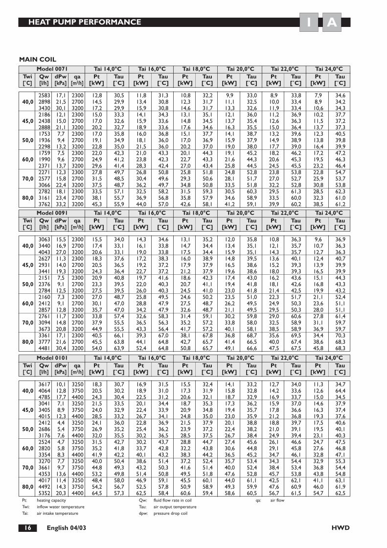
HWD16 English 04/03
HEAT PUMP PERFORMANCE AI
2583 17,1 2300 12,8 30,5 11,8 31,3 10,8 32,2 9,9 33,0 8,9 33,8 7,9 34,640,0 2898 21,5 2700 14,5 29,9 13,4 30,8 12,3 31,7 11,1 32,5 10,0 33,4 8,9 34,2
3430 30,1 3200 17,2 29,9 15,9 30,8 14,6 31,7 13,3 32,6 11,9 33,4 10,6 34,32186 12,1 2300 15,0 33,3 14,1 34,3 13,1 35,1 12,1 36,0 11,2 36,9 10,2 37,7
45,0 2438 15,0 2700 17,0 32,6 15,9 33,6 14,8 34,5 13,7 35,4 12,6 36,3 11,5 37,22888 21,1 3200 20,2 32,7 18,9 33,6 17,6 34,6 16,3 35,5 15,0 36,4 13,7 37,31753 7,7 2300 17,0 35,8 16,0 36,8 15,1 37,7 14,1 38,7 13,2 39,6 12,3 40,5
50,0 1936 9,4 2700 19,1 34,9 18,1 36,0 17,0 36,9 15,9 37,9 14,9 38,9 13,8 39,82298 13,2 3200 22,8 35,0 21,5 36,0 20,2 37,0 19,0 38,0 17,7 39,0 16,4 39,91759 7,5 2300 22,0 42,3 21,0 43,3 20,1 44,3 19,1 45,2 18,2 46,2 17,2 47,2
60,0 1990 9,6 2700 24,9 41,2 23,8 42,3 22,7 43,3 21,6 44,3 20,6 45,3 19,5 46,32371 13,7 3200 29,6 41,4 28,3 42,4 27,0 43,4 25,8 44,5 24,5 45,5 23,2 46,42271 12,3 2300 27,8 49,7 26,8 50,8 25,8 51,8 24,8 52,8 23,8 53,8 22,8 54,7
70,0 2577 15,8 2700 31,5 48,5 30,4 49,6 29,3 50,6 28,1 51,7 27,0 52,7 25,9 53,73066 22,4 3200 37,5 48,7 36,2 49,7 34,8 50,8 33,5 51,8 32,2 52,8 30,8 53,82782 18,1 2300 33,5 57,1 32,5 58,2 31,5 59,3 30,5 60,3 29,5 61,3 28,5 62,3
80,0 3161 23,4 2700 38,1 55,7 36,9 56,8 35,8 57,9 34,6 58,9 33,5 60,0 32,3 61,03762 33,2 3200 45,3 55,9 44,0 57,0 42,6 58,1 41,2 59,1 39,9 60,2 38,5 61,2
Twi Qw dPw qa Pt Tau Pt Tau Pt Tau Pt Tau Pt Tau Pt Tau[˚C] [l/h] [kPa] [m3/h] [kW] [˚C] [kW] [˚C] [kW] [˚C] [kW] [˚C] [kW] [˚C] [kW] [˚C]
Model 0071 Tai 14,0°C Tai 16,0°C Tai 18,0°C Tai 20,0°C Tai 22,0°C Tai 24,0°C
3063 15,5 2300 15,5 34,0 14,3 34,6 13,1 35,2 12,0 35,8 10,8 36,3 9,6 36,940,0 3440 16,9 2700 17,4 33,1 16,1 33,8 14,7 34,4 13,4 35,1 12,1 35,7 10,7 36,3
4043 27,0 3200 20,6 33,1 19,0 33,8 17,5 34,4 15,9 35,1 14,3 35,7 12,7 36,32627 11,3 2300 18,3 37,6 17,2 38,3 16,0 38,9 14,8 39,5 13,6 40,1 12,4 40,7
45,0 2931 14,0 2700 20,5 36,5 19,2 37,2 17,9 37,9 16,5 38,6 15,2 39,3 13,9 39,93441 19,3 3200 24,3 36,4 22,7 37,2 21,2 37,9 19,6 38,6 18,0 39,3 16,5 39,92151 7,5 2300 20,9 40,8 19,7 41,6 18,6 42,3 17,4 43,0 16,2 43,6 15,1 44,3
50,0 2376 9,1 2700 23,3 39,5 22,0 40,3 20,7 41,1 19,4 41,8 18,1 42,6 16,8 43,32784 12,5 3200 27,5 39,5 26,0 40,3 24,5 41,0 23,0 41,8 21,4 42,5 19,9 43,22160 7,3 2300 27,0 48,7 25,8 49,5 24,6 50,2 23,5 51,0 22,3 51,7 21,1 52,4
60,0 2412 9,1 2700 30,1 47,0 28,8 47,9 27,5 48,7 26,2 49,5 24,9 50,3 23,6 51,12857 12,8 3200 35,7 47,0 34,2 47,9 32,6 48,7 21,1 49,5 29,5 50,3 28,0 51,12761 11,7 2300 33,8 57,4 32,6 58,3 31,4 59,1 30,2 59,8 29,0 60,6 27,8 61,4
70,0 3094 14,8 2700 37,9 55,5 36,5 56,3 35,2 57,2 33,8 58,0 32,5 58,9 31,1 59,73673 20,8 3200 44,9 55,5 43,3 56,4 41,7 57,2 40,1 58,1 38,5 58,9 36,9 59,73361 17,1 2300 40,5 66,1 39,3 67,0 38,1 67,8 36,8 68,7 35,6 69,5 34,4 70,3
80,0 3777 21,6 2700 45,5 63,8 44,1 64,8 42,7 65,7 41,4 66,5 40,0 67,4 38,6 68,34481 30,4 3200 54,0 63,9 52,4 64,8 50,8 65,7 49,1 66,6 47,5 67,5 45,8 68,3
Twi Qw dPw qa Pt Tau Pt Tau Pt Tau Pt Tau Pt Tau Pt Tau[˚C] [l/h] [kPa] [m3/h] [kW] [˚C] [kW] [˚C] [kW] [˚C] [kW] [˚C] [kW] [˚C] [kW] [˚C]
Model 0091 Tai 14,0°C Tai 16,0°C Tai 18,0°C Tai 20,0°C Tai 22,0°C Tai 24,0°C
3617 10,1 3250 18,3 30,7 16,9 31,5 15,5 32,4 14,1 33,2 12,7 34,0 11,3 34,740,0 4064 12,8 3750 20,5 30,2 18,9 31,0 17,3 31,9 15,8 32,8 14,2 33,6 12,6 64,4
4785 17,7 4400 24,3 30,4 22,5 31,2 20,6 32,1 18,7 32,9 16,9 33,7 15,0 34,53041 7,1 3250 21,5 33,5 20,1 34,4 18,7 35,3 17,3 36,2 15,9 37,0 14,6 37,9
45,0 3405 8,9 3750 24,0 32,9 22,4 33,9 20,9 34,8 19,4 35,7 17,8 36,6 16,3 37,44015 12,3 4400 28,5 33,2 26,7 34,1 24,8 35,0 23,0 35,9 21,2 36,8 19,3 37,62412 4,4 3250 24,1 36,0 22,8 36,9 21,5 37,9 20,1 38,8 18,8 39,7 17,5 40,6
50,0 2686 5,4 3750 26,9 35,2 25,4 36,2 23,9 37,2 22,4 38,2 21,0 39,1 19,5 40,13176 7,6 4400 32,0 35,5 30,2 36,5 28,5 37,5 26,7 38,4 24,9 39,4 23,1 40,32524 4,7 3250 31,5 42,7 30,2 43,7 28,8 44,7 27,4 45,6 26,1 46,6 24,7 47,5
60,0 2820 5,8 3750 35,2 41,8 33,7 42,8 32,2 43,8 30,6 44,8 29,1 45,8 27,6 46,83354 8,3 4400 41,9 42,2 40,1 43,2 38,3 44,2 36,5 45,2 34,7 46,1 32,8 47,13270 7,7 3250 40,0 50,4 38,6 51,4 37,2 52,4 35,7 53,4 34,3 54,4 32,9 55,3
70,0 3661 9,7 3750 44,8 49,3 43,2 50,3 41,6 51,4 40,0 52,4 38,4 53,4 36,8 54,44353 13,6 4400 53,2 49,8 51,4 50,8 49,5 51,8 47,6 52,8 45,7 53,8 43,8 54,84017 11,4 3250 48,4 58,0 46,9 59,1 45,5 60,1 44,0 61,1 42,5 62,1 41,1 63,1
80,0 4492 14,3 3750 54,2 56,7 52,5 57,8 50,9 58,9 49,3 59,9 47,6 60,9 46,0 61,95352 20,3 4400 64,5 57,3 62,5 58,4 60,6 59,4 58,6 60,5 56,7 61,5 54,7 62,5
Twi Qw dPw qa Pt Tau Pt Tau Pt Tau Pt Tau Pt Tau Pt Tau[˚C] [l/h] [kPa] [m3/h] [kW] [˚C] [kW] [˚C] [kW] [˚C] [kW] [˚C] [kW] [˚C] [kW] [˚C]
Model 0101 Tai 14,0°C Tai 16,0°C Tai 18,0°C Tai 20,0°C Tai 22,0°C Tai 24,0°C
Pt: heating capacityTwi: inflow water temperatureTai: air intake temperature
Qw: fluid flow rate in coilTau: air output temperaturedpw: pressure drop coil
qa: air flow
MAIN COIL
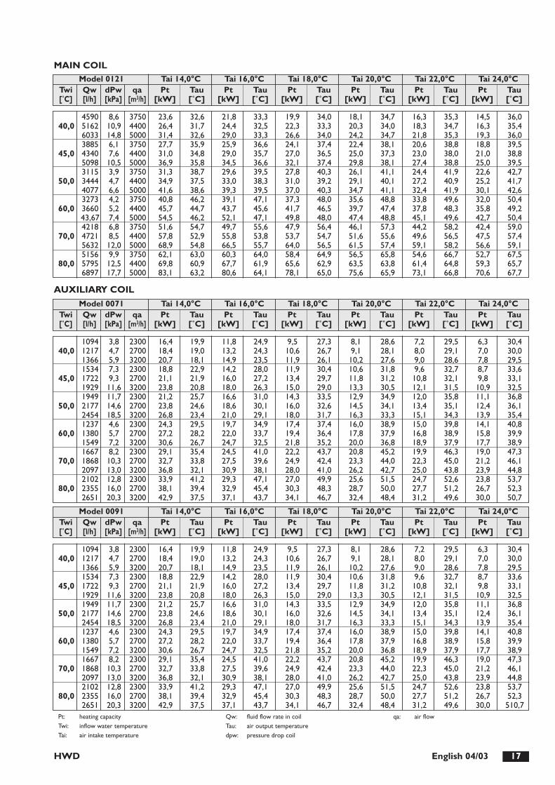
HWD 17English 04/03
4590 8,6 3750 23,6 32,6 21,8 33,3 19,9 34,0 18,1 34,7 16,3 35,3 14,5 36,040,0 5162 10,9 4400 26,4 31,7 24,4 32,5 22,3 33,3 20,3 34,0 18,3 34,7 16,3 35,4
6033 14,8 5000 31,4 32,6 29,0 33,3 26,6 34,0 24,2 34,7 21,8 35,3 19,3 36,03885 6,1 3750 27,7 35,9 25,9 36,6 24,1 37,4 22,4 38,1 20,6 38,8 18,8 39,5
45,0 4340 7,6 4400 31,0 34,8 29,0 35,7 27,0 36,5 25,0 37,3 23,0 38,0 21,0 38,85098 10,5 5000 36,9 35,8 34,5 36,6 32,1 37,4 29,8 38,1 27,4 38,8 25,0 39,53115 3,9 3750 31,3 38,7 29,6 39,5 27,8 40,3 26,1 41,1 24,4 41,9 22,6 42,7
50,0 3444 4,7 4400 34,9 37,5 33,0 38,3 31,0 39,2 29,1 40,1 27,2 40,9 25,2 41,74077 6,6 5000 41,6 38,6 39,3 39,5 37,0 40,3 34,7 41,1 32,4 41,9 30,1 42,63273 4,2 3750 40,8 46,2 39,1 47,1 37,3 48,0 35,6 48,8 33,8 49,6 32,0 50,4
60,0 3660 5,2 4400 45,7 44,7 43,7 45,6 41,7 46,5 39,7 47,4 37,8 48,3 35,8 49,243,67 7,4 5000 54,5 46,2 52,1 47,1 49,8 48,0 47,4 48,8 45,1 49,6 42,7 50,44218 6,8 3750 51,6 54,7 49,7 55,6 47,9 56,4 46,1 57,3 44,2 58,2 42,4 59,0
70,0 4721 8,5 4400 57,8 52,9 55,8 53,8 53,7 54,7 51,6 55,6 49,6 56,5 47,5 57,45632 12,0 5000 68,9 54,8 66,5 55,7 64,0 56,5 61,5 57,4 59,1 58,2 56,6 59,15156 9,9 3750 62,1 63,0 60,3 64,0 58,4 64,9 56,5 65,8 54,6 66,7 52,7 67,5
80,0 5795 12,5 4400 69,8 60,9 67,7 61,9 65,6 62,9 63,5 63,8 61,4 64,8 59,3 65,76897 17,7 5000 83,1 63,2 80,6 64,1 78,1 65,0 75,6 65,9 73,1 66,8 70,6 67,7
Twi Qw dPw qa Pt Tau Pt Tau Pt Tau Pt Tau Pt Tau Pt Tau[˚C] [l/h] [kPa] [m3/h] [kW] [˚C] [kW] [˚C] [kW] [˚C] [kW] [˚C] [kW] [˚C] [kW] [˚C]
Model 0121 Tai 14,0°C Tai 16,0°C Tai 18,0°C Tai 20,0°C Tai 22,0°C Tai 24,0°C
1094 3,8 2300 16,4 19,9 11,8 24,9 9,5 27,3 8,1 28,6 7,2 29,5 6,3 30,440,0 1217 4,7 2700 18,4 19,0 13,2 24,3 10,6 26,7 9,1 28,1 8,0 29,1 7,0 30,0
1366 5,9 3200 20,7 18,1 14,9 23,5 11,9 26,1 10,2 27,6 9,0 28,6 7,8 29,51534 7,3 2300 18,8 22,9 14,2 28,0 11,9 30,4 10,6 31,8 9,6 32,7 8,7 33,6
45,0 1722 9,3 2700 21,1 21,9 16,0 27,2 13,4 29,7 11,8 31,2 10,8 32,1 9,8 33,11929 11,6 3200 23,8 20,8 18,0 26,3 15,0 29,0 13,3 30,5 12,1 31,5 10,9 32,51949 11,7 2300 21,2 25,7 16,6 31,0 14,3 33,5 12,9 34,9 12,0 35,8 11,1 36,8
50,0 2177 14,6 2700 23,8 24,6 18,6 30,1 16,0 32,6 14,5 34,1 13,4 35,1 12,4 36,12454 18,5 3200 26,8 23,4 21,0 29,1 18,0 31,7 16,3 33,3 15,1 34,3 13,9 35,41237 4,6 2300 24,3 29,5 19,7 34,9 17,4 37,4 16,0 38,9 15,0 39,8 14,1 40,8
60,0 1380 5,7 2700 27,2 28,2 22,0 33,7 19,4 36,4 17,8 37,9 16,8 38,9 15,8 39,91549 7,2 3200 30,6 26,7 24,7 32,5 21,8 35,2 20,0 36,8 18,9 37,9 17,7 38,91667 8,2 2300 29,1 35,4 24,5 41,0 22,2 43,7 20,8 45,2 19,9 46,3 19,0 47,3
70,0 1868 10,3 2700 32,7 33,8 27,5 39,6 24,9 42,4 23,3 44,0 22,3 45,0 21,2 46,12097 13,0 3200 36,8 32,1 30,9 38,1 28,0 41,0 26,2 42,7 25,0 43,8 23,9 44,82102 12,8 2300 33,9 41,2 29,3 47,1 27,0 49,9 25,6 51,5 24,7 52,6 23,8 53,7
80,0 2355 16,0 2700 38,1 39,4 32,9 45,4 30,3 48,3 28,7 50,0 27,7 51,2 26,7 52,32651 20,3 3200 42,9 37,5 37,1 43,7 34,1 46,7 32,4 48,4 31,2 49,6 30,0 50,7
Twi Qw dPw qa Pt Tau Pt Tau Pt Tau Pt Tau Pt Tau Pt Tau[˚C] [l/h] [kPa] [m3/h] [kW] [˚C] [kW] [˚C] [kW] [˚C] [kW] [˚C] [kW] [˚C] [kW] [˚C]
Model 0071 Tai 14,0°C Tai 16,0°C Tai 18,0°C Tai 20,0°C Tai 22,0°C Tai 24,0°C
1094 3,8 2300 16,4 19,9 11,8 24,9 9,5 27,3 8,1 28,6 7,2 29,5 6,3 30,440,0 1217 4,7 2700 18,4 19,0 13,2 24,3 10,6 26,7 9,1 28,1 8,0 29,1 7,0 30,0
1366 5,9 3200 20,7 18,1 14,9 23,5 11,9 26,1 10,2 27,6 9,0 28,6 7,8 29,51534 7,3 2300 18,8 22,9 14,2 28,0 11,9 30,4 10,6 31,8 9,6 32,7 8,7 33,6
45,0 1722 9,3 2700 21,1 21,9 16,0 27,2 13,4 29,7 11,8 31,2 10,8 32,1 9,8 33,11929 11,6 3200 23,8 20,8 18,0 26,3 15,0 29,0 13,3 30,5 12,1 31,5 10,9 32,51949 11,7 2300 21,2 25,7 16,6 31,0 14,3 33,5 12,9 34,9 12,0 35,8 11,1 36,8
50,0 2177 14,6 2700 23,8 24,6 18,6 30,1 16,0 32,6 14,5 34,1 13,4 35,1 12,4 36,12454 18,5 3200 26,8 23,4 21,0 29,1 18,0 31,7 16,3 33,3 15,1 34,3 13,9 35,41237 4,6 2300 24,3 29,5 19,7 34,9 17,4 37,4 16,0 38,9 15,0 39,8 14,1 40,8
60,0 1380 5,7 2700 27,2 28,2 22,0 33,7 19,4 36,4 17,8 37,9 16,8 38,9 15,8 39,91549 7,2 3200 30,6 26,7 24,7 32,5 21,8 35,2 20,0 36,8 18,9 37,9 17,7 38,91667 8,2 2300 29,1 35,4 24,5 41,0 22,2 43,7 20,8 45,2 19,9 46,3 19,0 47,3
70,0 1868 10,3 2700 32,7 33,8 27,5 39,6 24,9 42,4 23,3 44,0 22,3 45,0 21,2 46,12097 13,0 3200 36,8 32,1 30,9 38,1 28,0 41,0 26,2 42,7 25,0 43,8 23,9 44,82102 12,8 2300 33,9 41,2 29,3 47,1 27,0 49,9 25,6 51,5 24,7 52,6 23,8 53,7
80,0 2355 16,0 2700 38,1 39,4 32,9 45,4 30,3 48,3 28,7 50,0 27,7 51,2 26,7 52,32651 20,3 3200 42,9 37,5 37,1 43,7 34,1 46,7 32,4 48,4 31,2 49,6 30,0 510,7
Twi Qw dPw qa Pt Tau Pt Tau Pt Tau Pt Tau Pt Tau Pt Tau[˚C] [l/h] [kPa] [m3/h] [kW] [˚C] [kW] [˚C] [kW] [˚C] [kW] [˚C] [kW] [˚C] [kW] [˚C]
Model 0091 Tai 14,0°C Tai 16,0°C Tai 18,0°C Tai 20,0°C Tai 22,0°C Tai 24,0°C
Pt: heating capacityTwi: inflow water temperatureTai: air intake temperature
Qw: fluid flow rate in coilTau: air output temperaturedpw: pressure drop coil
qa: air flow
AUXILIARY COIL
MAIN COIL

HWD18 English 04/03
Pt: heating capacityTwi: inflow water temperatureTai: air intake temperature
Qw: fluid flow rate in coilTau: air output temperaturedpw: pressure drop coil
qa: air flow
1627 5,4 3250 24,0 20,7 17,4 25,5 14,0 27,8 12,0 29,1 10,7 30,0 9,3 30,840,0 1794 6,6 3750 26,6 19,8 19,2 24,9 15,5 27,3 13,3 28,7 11,8 29,6 10,3 30,4
1991 8,1 4400 29,8 18,9 21,5 24,2 17,3 26,7 14,8 28,1 13,1 29,1 11,5 30,02263 10,4 3250 27,5 23,7 20,9 28,7 17,5 31,0 15,5 32,4 14,2 33,3 12,8 34,1
45,0 2511 12,8 3750 30,6 22,8 23,1 27,9 19,4 30,4 17,2 31,8 15,7 32,7 14,2 33,62795 15,9 4400 34,2 21,7 25,9 27,1 21,7 29,7 19,2 31,1 17,5 32,1 15,9 33,02857 16,3 3250 31,0 26,6 24,3 31,7 20,9 34,1 18,9 35,5 17,6 36,4 16,3 37,3
50,0 3166 20,1 3750 34,3 25,6 26,9 30,9 23,2 33,4 21,0 34,8 19,5 35,8 18,0 36,73537 25,0 4400 38,5 24,4 30,1 29,9 25,9 32,5 23,4 34,0 21,8 35,0 20,1 36,01825 6,5 3250 35,6 30,6 28,9 35,8 25,5 38,3 23,5 39,8 22,1 40,7 20,8 41,6
60,0 2016 7,9 3750 39,4 29,3 31,9 34,8 28,2 37,4 26,0 38,8 24,5 39,8 23,0 40,82245 9,8 4400 44,0 28,0 35,7 33,6 31,5 36,3 29,0 37,8 27,3 38,9 25,6 39,92446 11,5 3250 42,6 36,6 35,8 42,1 32,5 44,7 30,5 46,2 29,1 47,2 27,8 48,2
70,0 2708 14,0 3750 47,2 35,1 39,7 40,8 36,0 43,5 33,8 45,1 32,3 46,1 30,8 47,23024 17,5 4400 52,8 33,5 44,4 39,4 40,2 42,2 37,7 43,8 36,1 44,9 34,4 45,93067 17,7 3250 49,5 42,5 42,8 48,3 39,4 51,1 37,4 52,7 36,1 53,7 34,7 54,8
80,0 3401 21,7 3750 54,9 40,9 47,5 46,8 43,7 49,6 41,5 51,3 40,0 52,4 38,5 53,53809 27,3 4400 61,5 39,0 53,1 45,1 48,9 48,0 46,4 49,8 44,8 50,9 43,1 52,0
Twi Qw dPw qa Pt Tau Pt Tau Pt Tau Pt Tau Pt Tau Pt Tau[˚C] [l/h] [kPa] [m3/h] [kW] [˚C] [kW] [˚C] [kW] [˚C] [kW] [˚C] [kW] [˚C] [kW] [˚C]
Model 0101 Tai 14,0°C Tai 16,0°C Tai 18,0°C Tai 20,0°C Tai 22,0°C Tai 24,0°C
1775 6,4 3750 26,4 19,7 19,1 24,8 15,4 27,2 13,2 28,6 11,7 29,5 10,2 30,340,0 1979 8,0 4400 29,6 18,8 21,3 24,1 17,2 26,6 14,7 28,0 13,0 29,0 11,4 29,9
2152 9,5 5000 32,3 18,0 23,2 23,5 18,7 26,1 16,0 27,6 14,2 28,6 12,4 29,62486 12,5 3750 30,3 22,6 22,9 27,8 19,2 30,2 17,0 31,7 15,6 32,6 14,1 33,5
45,0 2770 15,5 4400 33,9 21,5 25,6 27,0 21,5 29,5 19,0 31,0 17,4 32,0 15,7 32,93017 18,4 5000 37,0 20,7 28,0 26,3 23,5 28,9 20,7 30,5 18,9 31,5 17,1 32,53129 19,5 3750 34,1 25,4 26,7 30,7 23,0 33,2 20,8 34,7 19,3 35,6 17,8 36,6
50,0 3500 24,4 4400 38,1 24,2 29,9 29,7 25,7 32,4 23,2 33,9 21,6 34,9 19,9 35,93821 29,0 5000 41,7 23,3 32,6 29,0 28,1 31,7 25,4 33,3 23,5 34,5 21,7 35,31998 7,8 3750 39,1 29,1 31,7 34,6 28,0 37,2 25,7 38,7 24,3 39,6 22,8 40,6
60,0 2226 9,6 4400 43,7 27,7 35,4 33,4 31,2 36,1 28,7 37,7 27,1 38,7 25,4 39,72424 11,4 5000 47,7 26,6 38,63 32,4 34,0 35,2 31,3 36,8 29,5 37,9 27,6 39,02684 13,7 3750 46,8 34,8 39,4 40,5 35,7 43,3 33,5 44,9 32,0 45,9 30,5 46,9
70,0 2999 17,1 4400 52,4 33,2 44,1 39,1 39,9 41,9 37,4 43,6 35,7 44,7 34,1 45,73271 20,4 5000 57,2 31,9 48,1 38,0 43,5 40,9 40,8 42,6 39,0 43,7 37,2 44,83376 21,3 3750 54,5 40,6 47,1 46,5 43,4 49,4 41,2 51,0 39,7 52,1 38,2 53,2
80,0 3772 26,6 4400 61,0 38,7 52,7 44,8 48,5 47,8 46,0 49,5 44,4 50,6 42,7 51,84118 31,7 5000 66,6 37,2 57,5 43,5 530 46,5 50,3 48,3 48,4 49,4 46,6 50,6
Twi Qw dPw qa Pt Tau Pt Tau Pt Tau Pt Tau Pt Tau Pt Tau[˚C] [l/h] [kPa] [m3/h] [kW] [˚C] [kW] [˚C] [kW] [˚C] [kW] [˚C] [kW] [˚C] [kW] [˚C]
Model 0121 Tai 14,0°C Tai 16,0°C Tai 18,0°C Tai 20,0°C Tai 22,0°C Tai 24,0°C
AUXILIARY COIL

HWD 19English 04/03
Models DimensionsA B H C C1 F F1
9 8
B 15 B 250 B
FF1 H C
1
A C
144 15 B 15 B
1
UNITÁ BASE CANALIZZABILE
7 2 3 6 5 4
1 fan module (basic unit) 5 intake plenum 10 discharge grill module2 heat exchange module (basic unit) 6 two way intake plenum with damper3 air filter module (basic unit) 7 hot water coil module for winter heating4 intake grill module 9 discharge plenum
0071-0091 1300 495 510 1265 478 1204 3860101-0121 1500 610 625 1465 593 1404 501
ACCESSORIESAI
D 15 B
A
E C
40 383
Model Amm Bmm Cmm Dmm Emm0071-0091 1300 495 510 1267 4800101-0121 1500 610 625 1467 595
All models are supplied ready for fixing to the dischargeflange of the basic unit, another module or directly to theducting. Always include the gasket between one moduleand another.
TWO WAY INTAKE PLENUM WITH DAMPERThe two way intake plenum with damper enables the roomair intake duct and the external air intake duct to be con-nected when required by the installation.The plenum is regulated by means of a manual damperwhich can be automated, following removal of the handwheel (the motorised control is not supplied).
The cross section of the external air intake duct is 25% thetotal cross section.It is mounted with a direct connection to the heat exchan-ger module.When the two way intake plenum is fitted, the filter can beremoved sideways by removing the side panel on the dam-per regulation hand wheel side. To remove the filterdownwards, the bottom panel of the module itself must beremoved.

HWD20 English 04/03
BA30
C 150
DD
123 44 83
Model Amm B1mm Dmm Emm Ø Att. Idr. Gas0071-0091 1300 250 510 180 3/4”0101-0121 1500 250 625 237,5 1”
AUXILIARY HOT WATER COIL MODULE FORWINTER HEATINGThe hot water coil module for winter heating is fitted infour-pipe installations when a heat pump unit is not usedfor room heating. It can also be used as a coil for summer after-heating. Thecoil module can be mounted using right or left hand con-nections.
The coil is fitted with special valves for venting the air ordraining the water in the coil when not in use or to pre-vent freezing. The coil module can also be fitted with on/offor modulating regulator valves. In both the horizontal and vertical configurations, the coilis mounted between the main heat exchanger module andthe fan module.
D 15 B
A
E C
Model Amm Bmm Cmm Dmm Emm0071-0091 1300 495 510 1267 4800101-0121 1500 610 625 1467 595
DISCHARGE (AND INTAKE) PLENUMThe discharge and intake plenum is used when the flow ofair must be diverted from the horizontal to the vertical.The male part protruding by 15 mm must be coupled to theheat exchanger module when used as an intake plenum andthe fan or electric resistor module when used as a dischargeplenum. The procedure for mounting as an intake plenum on
the heat exchanger module or as a discharge plenum on thefan module is the same as for joining the heat exchanger andfan modules. When an intake plenum is fitted, the filter can beremoved sideways by removing the panel from the connec-tions side of the plenum. The filter can be removed downwardsby removing the bottom panel of the plenum itself.

HWD 21English 04/03
4
3
C
B
A
2
1
5
3
C
INTAKE AND DISCHARGE GRILLSThe intake and discharge grills are designed for directmounting onto the respective intake and discharge ple-nums. A grill is not available for the two way intake plenumwith damper.The discharge grill has independently horizontally and ver-tically orientable slats.In the vertical configuration, the intake and discharge ple-nums together with their respective grills can be used toconstruct a cabinet type configuration for room installation(see drawing).
To obtain this configuration, proceed as follows:- On the heat exchanger module, move panel “A” into the
position of filter “B” and vice versa;- On the intake plenum, move panel “C” into the position
shown and mount the intake grill in the recess left empty.- On the discharge plenum, move panel “C” into the posi-
tion shown and mount the orientable discharge grill inthe recess left empty.
1 fan module
2 heat exchanger module
3 intake/discharge plenum
4 intake grill
5 discharge grill
A heat exchanger module panel
B filter
C intake/discharge plenum panel

HEAT OUTPUT OF AUXILIARY HOT WATER COIL AI
HWD22 English 04/03
Twi: intake water temperature Pt: heat output The area enclosed by the dotted line refers to
Q: water flow rate Tau: air outflow temperature industrial type operating conditions
∅Pw: pressure drop water side Tai: intake air temperature Data refer to rated conditions
Model 0071-0091 Tai: -5°C Tai: 0°C Tai:10°C Tai:15°C Tai: 20°C Tai: 22°C
Model 0101 Tai: -5°C Tai: 0°C Tai:10°C Tai:15°C Tai: 20°C Tai: 22°C
Model 0121 Tai: -5°C Tai: 0°C Tai:10°C Tai:15°C Tai: 20°C Tai: 22°C
Twi Q ∅Pw Pt Tau Pt Tau Pt Tau Pt Tau Pt Tau Pt Tau°C l/h kPa kW °C kW °C kW °C kW °C kW °C kW °C
1370 5 29,8 22,9 27,6 25,8 23,3 31,7 20,9 34,6 18,7 37,4 17,9 38,760 1700 8 31,0 24,0 28,8 26,9 24,2 32,6 21,9 35,4 19,5 38,2 18,7 39,4
2200 13 32,3 25,2 30,0 28,0 25,2 33,5 22,8 36,3 20,3 39,0 19,4 40,01370 5 34,6 27,3 32,4 30,3 28,0 36,1 25,8 39,1 23,1 42,0 22,7 43,1
70 1700 8 36,0 28,7 33,8 31,5 29,2 37,3 26,9 40,1 24,0 42,9 23,6 44,02200 13 37,4 30,0 35,1 32,8 30,4 38,4 27,9 41,1 25,0 43,9 24,5 44,91370 5 39,3 31,7 37,2 34,8 32,8 40,6 30,6 43,6 28,2 46,3 27,4 47,6
80 1700 8 41,0 33,3 38,7 36,2 34,1 41,9 31,9 44,8 29,5 47,5 28,6 48,72200 13 44,3 36,4 40,2 37,6 35,5 43,2 33,1 45,9 30,6 48,7 29,8 49,8
Twi Q ∅Pw Pt Tau Pt Tau Pt Tau Pt Tau Pt Tau Pt Tau°C l/h kPa kW °C kW °C kW °C kW °C kW °C kW °C
1950 7 42,4 23,9 39,3 26,7 33,0 32,4 29,9 35,3 26,6 38,0 25,4 39,260 2450 11 44,3 35,4 41,0 27,8 34,4 33,4 31,2 36,1 27,7 38,8 26,5 39,9
3200 19 46,0 26,2 42,5 28,9 35,8 34,3 32,4 36,9 28,9 39,6 27,5 40,71950 7 49,2 28,4 46,0 31,3 39,8 37,0 36,7 39,9 33,5 42,7 32,2 43,9
70 2450 11 51,3 29,9 48,3 32,6 41,5 38,2 38,3 41,0 34,9 43,7 33,5 44,73200 19 53,2 31,1 49,8 33,9 43,1 39,3 39,7 42,0 36,0 44,5 34,9 45,61950 7 56,1 33,2 52,8 35,9 46,7 41,7 43,5 44,5 40,2 47,3 39,0 48,5
80 2450 11 58,2 34,6 55,0 37,4 48,6 43,0 45,3 45,8 42,1 48,6 40,7 49,63200 19 60,4 36,1 57,1 38,8 50,4 44,3 47,0 46,9 43,7 49,6 42,2 50,6
Twi Q ∅Pw Pt Tau Pt Tau Pt Tau Pt Tau Pt Tau Pt Tau°C l/h kPa kW °C kW °C kW °C kW °C kW °C kW °C
2050 8 45,5 22,2 42,2 25,2 35,5 31,2 32,0 34,1 28,6 37,1 27,3 38,360 2600 13 47,6 23,4 44,1 26,4 37,0 32,1 33,5 35,0 29,9 37,8 28,5 39,0
3400 22 49,5 24,6 45,9 27,4 38,6 33,0 34,9 35,8 31,2 38,6 29,7 39,72050 8 52,7 26,5 49,4 29,6 42,8 35,6 39,3 38,5 35,9 41,4 34,6 42,7
70 2600 13 55,1 27,9 51,6 30,9 44,7 36,7 41,2 39,6 37,5 42,4 36,1 43,63400 22 57,3 29,3 53,7 32,1 46,5 37,8 42,8 40,6 39,0 43,4 37,6 44,52050 8 60,0 30,9 56,7 33,9 50,1 39,9 46,6 42,8 43,3 45,9 41,9 47,0
80 2600 13 62,7 32,5 59,3 35,4 52,3 41,3 48,8 44,1 45,3 47,0 43,8 48,13400 22 65,1 33,9 61,5 36,8 54,3 42,5 50,7 45,3 47,0 48,0 45,5 49,2

PRESSURE DROP WITH ACCESSORIES
HWD 23English 04/03
AI
Model Q Air m3/h 2600 3200 3800 4400 5000 56000101 ∅pa (Pa) 7 11 15 21 26 33
Model Q Air m3/h 2600 3200 3800 4400 5000 56000121 ∅pa (Pa) 7 11 15 21 26 33
Model Q Air m3/h 2400 2600 2800 3000 3200 3400 3800 4400 5000 5600
PRESSURE DROP AIR SIDE TWO WAY INTAKE MODULE
Note: damper in 45° position
PRESSURE DROP AIR SIDE AUXILIARY WATER COIL
PRESSURE DROP INTAKE GRILL
PRESSURE DROP SINGLE ELECTRIC RESISTOR MODULE
Model Q Air m3/h 2400 2600 2800 3000 3200 34000071-0091 ∅pa (Pa) 13 15 18 21 23 26
Model Q Air m3/h 2400 2600 2800 3000 3200 3400 3800 4400 5000 5600
Model Q Air m3/h 2400 2600 2800 3000 3200 3400 3800 4400 5000 5600
Data refer to rated conditions.
0071-0091 ∅pa (Pa) 4,2 5,0 5,9 6,7 7,5 8,5 - - - -0101 ∅pa (Pa) - 3,0 3,5 4,0 4,5 5,0 6,4 8,5 11,0 -0121 ∅pa (Pa) - - - 4,3 4,9 5,5 7,0 9,2 12,0 15,0
0071-0091 ∅pa (Pa) 3,0 3,3 3,8 4,4 5,0 5,7 - - - - -0101 ∅pa (Pa) - 1,5 1,7 1,9 2,1 2,3 3,0 4,0 5,0 - -0121 ∅pa (Pa) - - - 1,9 2,1 2,3 3,0 4,0 5,0 6,5 -
0071-0091 ∅pa (Pa) 2,0 2,5 3,0 3,5 4,0 4,5 - - - -0101 ∅pa (Pa) - 3,0 3,5 4,0 4,5 5,0 6,4 8,5 11,0 -0121 ∅pa (Pa) - - - 4,0 4,5 5,0 6,4 8,5 11,0 13,8
Data refer to rated conditions.
PRESSURE DROP ORIENTABLE DISCHARGE GRILL
Model Q Air m3/h 2400 2600 2800 3000 3200 3400 3800 4400 5000 5600
Data refer to rated conditions.
0071-0091 ∅pa (Pa) 5,5 6,5 7,5 8,8 10,0 11,0 - - - -0101 ∅pa (Pa) - 2,8 3,2 3,7 4,2 4,8 6,0 8,0 10,0 -0121 ∅pa (Pa) - - - 3,7 4,2 4,8 6,0 8,0 10,0 13,0

COMMISSIONING
HWD24 English 04/03
CHECKING THE COIL1. Check the internal unit is correctly positioned and that
electrical and hydraulic connections between the exter-nal and internal units are correct;
2. Check that the voltage and frequency are equal to230V ±10%;
3. Check that the screws fastening the conductors to theelectrical components have not worked loose;
4. Check the condensate drain connection;5. Check that the outlet is ducted;6. Check the tightness of the circuit by putting it under
pressure;
START-UPDuring the summer, start up the external unit in air condi-tioning only. During the winter, start it up in heating only.
FIRST START UP CHECKS1. Check that fan absorption is below the peak current
indicated in the table on page 11;2. Check correct fan speed calibration in relation to
system requirements.
AI
DESCRIPTION OF ELECTROMECHANICAL CONTROL UNIT
PTH2The PTH2 control unit acts as:1. fan speed selector to select a fan speed from minimum ,
medium and maximum. The set value of maximumspeed only can be modified by means of the potentio-meter on the electrical board of the unit.
2. Summer/Winter/Fan selector3. Room thermostat4. ON/OFF switch5. automatic/manual selector

HWD 25English 04/03
FAN CALIBRATION
Each model is supplied with the fan performance characte-ristics, max. speed, medium speed and minimum speed, asindicated in the respective diagrams of each unit for thecurves A, B and C (see page 12-13). If the performance needs to be increased to overcomeadditional pressure drop and keep the nominal air flowconstant, a residual head is available as shown in curve D. Maximum flow can be increased by using the trimmer RP1on the regulation board inside the switchboard. Access the board by removing the switchboard cover. Increasing maximum speed (by rotating trimmer RP1 anti-clockwise) automatically increases medium and minimumspeed by the same amount.Reducing maximum speed (by rotating the trimmer RP1clockwise) reduces the difference between maximum andmedium speeds and minimum speed. For convenience, the difference between the maximumspeed set (curve A) and the maximum speed available
(curve D) has been divided into seven equal parts as repre-sented in the respective diagrams. The voltage increase corresponding to each curve is givenby the formula:
V1= (230V - V) V1= voltage increase7 V = tension at maximum set speed
(see table)
Identifying the curve corresponding to the pressure dropto be overcome also gives the voltage for calibrating maxi-mum speed using trimmer RP1:[voltage at maximum speed +(V1 x no. curve)].Always verify the voltage to the fan after every new calibration.The calibration voltages for the various speeds for eachmodel are given below:
HWD model 0071 0091 0101 0121
Voltage at minimum speed (V) 120 120 155 165Voltage at medium speed (V) 135 135 165 190
Voltage at maximum speed (V) 170 170 195 220
AI
Note: the regulation obtained using the above method is adequate but not precise. It is therefore good practice to check the actual air flow by measuring the air speed in the duct.

HWD26 English 04/03
IMPORTANT:- Power to the unit must be disconnected before carrying
out maintenance or cleaning.- At the beginning of each season you are recommended
to contact qualified personnel for the seasonal start-up.
To maintain correct functioning over time, a number ofessential and simple operations and controls should be car-ried out. These do not require the intervention of qualifiedpersonnel and can be carried out by the user:1. Checking the state of cleanliness of the air filters;2. Checking the coil;3. Checking the structural condition of the unit.
CHECKING THE STATE OF CLEANLINESS OFTHE AIR FILTERSThe filter can be removed from the bottom or from theconnections side of the unit. This is also possible when anintake or two way intake plenum with damper is fitted (seeplenum description).
Removing and cleaning filters1. Remove the door from the relevant side by unscrewing
the fixing screws. 2. Remove the air filter gently from the bottom, avoiding
dispersion of dust in the atmosphere. The filter is divi-ded into two sections to facilitate removal.
3. Wash the filtrant layer with warm water and ordinarydetergent, rinse and dry carefully.
ROUTINE MAINTENANCE
CHECKING THE COIL1. Remove encrustation and dirt from the coil.2. Check that the aluminium fins are not bent. If neces-
sary, “comb” them straight with a special implement torestore correct air flow through the coil.
CHECKING THE STRUCTURAL STATE OF THE UNIT1. Check the state of preservation of the unit as a whole.2. Check there is no rust and if necessary, treat affected
parts with rust preventer paint.3. Check the fixing of external panels.4. Verify the condition of internal heat insulation and
soundproofing.5. Check that fixing elements do not produce undue noise
and/or vibrations.6. Check that the condensate is draining correctly and
that the pan is free from encrustation.7. Check that the power cable is in good condition and
that there are no cuts or cracks.
AIU

USEFUL INFORMATIONU I A
For information on technical assistance and obtaining spare parts, contact
CLIMAVENETA S.P.A.AFTER SALES DEPARTMENT - RESIDENTIAL BUSINESSVia Duca d’Aosta 121 - 31031 Mignagola di Carbonera (TV) ITALY
TEL: +39.0424.509500FAX: +39.0424.509563
www.climaveneta.com - [email protected]
www.climaveneta.com
Climaveneta S.p.A. Via Sarson 57/c36061 Bassano del Grappa (VI)ItalyTel +39 0424 509 500Fax +39 0424 509 [email protected]
Climaveneta France 3, Village d’EntreprisesZA de la Couronne des PrésAvenue de la Mauldre78680 EpôneFranceTel +33 (0)1 30 95 19 19Fax +33 (0)1 30 95 18 [email protected]
Climaveneta Deutschland GmbHLyrenstraße 13 44866 Bochum Germany Tel +49 2327-95428-0 Fax +49 2327-95428-99 [email protected] www.climaveneta.de
Climaveneta España - Top Clima Londres 67, 1 4 08036 BarcelonaSpainTel +34 934 195 600Fax +34 934 195 [email protected]
Climaveneta Chat Union Refrig. Equipment Co Ltd88 Bai Yun Rd, Pudong XinghuoNew dev. zone 201419 ShanghaiChinaTel 008 621 575 055 66Fax 008 621 575 057 97
Climaveneta Polska Sp. z o.o. Ul. Sienkiewicza 13A,05-120 Legionowo,PolandTel +48 22 766 34 55-57Fax +48 22 784 39 [email protected]
Climaveneta Climate Technologies (P) Ltd #3487, 14th Main, HAL 2nd stage,Indiranagar, Bangalore 560008IndiaTel:+91-80-42466900 - 949, Fax: [email protected]
Climaveneta UK LTD. Highlands Road,Shirley SolihullWest Midlands B90 4NLTel: +44 (0)871 663 0664Fax: +44 (0)871 663 1664Freephone: 0800 801 [email protected]
CO
D. 5
7690
1120
0 (0
7/20
13)