Embed Size (px)
Citation preview
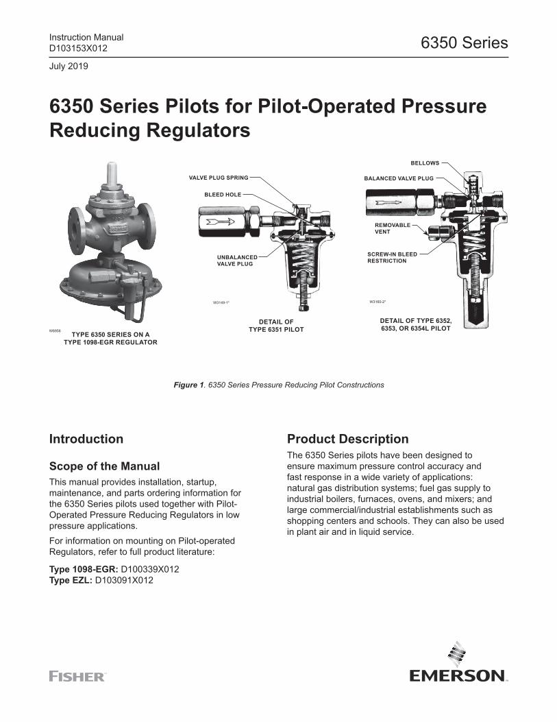
W6956
W3149-1* W3160-2*
6350 Series Pilots for Pilot-Operated Pressure Reducing Regulators
Figure 1. 6350 Series Pressure Reducing Pilot Constructions
TYPE 6350 SERIES ON A TYPE 1098-EGR REGULATOR
VALVE PLUG SPRING
BLEED HOLE
UNBALANCED VALVE PLUG
DETAIL OF TYPE 6351 PILOT
DETAIL OF TYPE 6352, 6353, OR 6354L PILOT
SCREW-IN BLEED RESTRICTION
REMOVABLE VENT
BALANCED VALVE PLUG
BELLOWS
Introduction
Scope of the ManualThis manual provides installation, startup, maintenance, and parts ordering information for the 6350 Series pilots used together with Pilot-Operated Pressure Reducing Regulators in low pressure applications.For information on mounting on Pilot-operated Regulators, refer to full product literature:
Type 1098-EGR: D100339X012Type EZL: D103091X012
Product DescriptionThe 6350 Series pilots have been designed to ensure maximum pressure control accuracy and fast response in a wide variety of applications: natural gas distribution systems; fuel gas supply to industrial boilers, furnaces, ovens, and mixers; and large commercial/industrial establishments such as shopping centers and schools. They can also be used in plant air and in liquid service.
Instruction ManualD103153X012
July 2019
6350 Series
Principle of OperationPilot-operated regulators use inlet pressure as the operating medium, which is reduced through pilot operation to load the actuator diaphragm. Outlet or downstream pressure opposes loading pressure in the actuator and also opposes the pilot control spring.In operation, assume that outlet pressure is below the pilot control setting. Control spring force on the pilot diaphragm thus opens the pilot valve plug providing additional loading pressure to the actuator diaphragm. This loading pressure forces the actuator stem forward, opening the main valve plug via a bump connection. The upward motion of the plug allows gas to flow through the cage into the downstream system.When downstream demand has been satisfied, outlet pressure will increase, acting on the pilot and actuator diaphragm. This pressure exceeds the pilot control spring setting, moving the pilot diaphragm away and
letting the valve plug spring (Type 6351) or bellows (Types 6352 through 6354M pilots) close the pilot valve plug (unbalanced in the Type 6351 but balanced in the Types 6352 through 6354M pilots). Excess loading pressure on the actuator diaphragm escapes downstream through the bleed hole (Type 6351 pilot) or restriction (Types 6352 through 6354M pilots). Reduced actuator loading pressure permits the main valve to close. The combination of main valve spring force and valve plug unbalance provides positive valve plug shutoff against the port and upper seals. All 6350 Series pilots have an internal check valve that allows loading pressure to bleed downstream at approximately 25 psig / 1.7 bar differential across the actuator diaphragm.
SpecificationsThe Specifications section lists pressure limitations and other specifications for various models of 6350 Series pilots. Please note that the pilot control spring range is displayed on the pilot spring case, and the pilot restriction code is stamped on the pilot body (S=standard gain, L=low gain, H=high gain).
Maximum Pilot Supply Pressure(1)(2)
600 psig / 41.4 bar
Outlet Pressure RangesSee Table 1
Process Temperature Capabilities(1) Standard Elastomers: -20 to 150°F / -29 to 66°C High-Temperature Elastomers: 0 to 300°F / -18 to 149°C, except 0 to 180°F / -18 to 82°C for water service
Pilot Restriction Code S - Standard gainL - Low GainH - High gain
Connections(3) 1/4 NPT internal
Approximate Weight 2 pounds / 1 kg
1. The pressure/temperature limits in this instruction manual or any applicable standard limitation should not be exceeded.2. For stability or overpressure protection, a reducing regulator may be installed upstream of the pilot according to the Installation section.3. Connections threaded to various national or international standards can usually be supplied. Contact your local Sales Office.
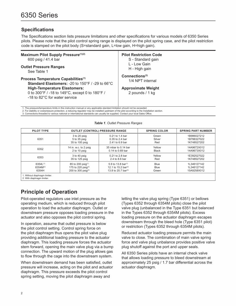
Table 1. Outlet Pressure Ranges
PILOT TYPE OUTLET (CONTROL) PRESSURE RANGE SPRING COLOR SPRING PART NUMBER
6351 3 to 20 psig 5 to 35 psig
35 to 100 psig
0.21 to 1.4 bar0.35 to 2.4 bar2.41 to 6.9 bar
GreenSilverRed
1B9860272121B7883270221K748527202
6352 14 in. w.c. to 2 psig 2 to 10 psig
35 mbar to 0.14 bar0.14 to 0.69 bar
YellowBlack
14A9672X01214A9673X012
6353 3 to 40 psig 35 to 125 psig
0.21 to 2.8 bar2.4 to 8.6 bar
YellowRed
1E3925270221K748527202
6354L(1)
6354M(2)
6354H
85 to 200 psig(1)
175 to 220 psig(2)
200 to 300 psig(2)
5.9 to 13.8 bar(1)
12.1 to 15.2 bar(2)
13.8 to 20.7 bar(2)
BlueBlue
Green
1L3461271421L34612714215A9258X012
1. Without diaphragm limiter.2. With diaphragm limiter.
2
6350 Series
!
!
!
Installation and Startup1. Use qualified personnel when installing, operating
and maintaining pilots. Before installing, inspect pilot and tubing, for any shipment damage or foreign material that may have collected during crating and shipment. Make certain that body is clean and the pipelines are free of foreign material.
In hazardous or flammable gas service, vented gas may accumulate, and cause personal injury, death, or property damage due to fire or explosion.Vent a regulator in hazardous gas service to a remote, safe location away from air intakes or any hazardous location. The vent line or stack opening must be protected against condensation or clogging.
2. To keep the pilot spring case vent from being plugged or the spring case from collecting moisture, corrosive chemicals, or other foreign material, point the vent down or otherwise protect it. To remotely vent the standard pilot, remove the vent and install obstruction-free tubing or piping into the 1/4 NPT vent tapping. Provide protection on a remote vent by installing a screened vent cap into the remote end of the vent pipe.
3. Run a 3/8 in. / 9.5 mm outer diameter or larger pilot supply line from the upstream pipeline to the filter inlet. Do not make the upstream pipeline connection in a turbulent area, such as near a nipple, swage, or elbow. If the maximum pilot inlet pressure could exceed the pilot rating, install a separate reducing regulator in the pilot supply line. Install a hand valve in the pilot supply line, and provide vent valves to properly isolate and relieve the pressure from the regulator.
Introduce pilot supply pressure into the regulator before introducing any downstream pressure, or internal damage may occur due to reverse pressurization of the pilot and main valve components.
4. Pressure setting of pilot control spring: Turning the adjusting screw clockwise into the spring case increases the spring compression and pressure setting. Turning the adjusting screw counterclockwise decreases the spring compression and pressure setting.
Pilot AdjustmentTo adjust standard 6350 Series pilots: loosen the locknut and turn the adjusting screw. Then tighten the locknut to maintain the adjustment position. A closing cap must be removed before adjustment and replaced afterward.
To avoid possible personal injury from a pressure-loaded pilot, carefully vent the spring case before removing the closing cap. Otherwise, trapped loading pressure could forcefully eject the freed closing cap.
MaintenancePilot parts are subject to normal wear and must be inspected and replaced as necessary. The frequency of inspection and replacement of parts depends upon the severity of service conditions or the requirements of local, state, and federal regulations. Due to the care Fisher™ takes in meeting all manufacturing requirements (heat treating, dimensional tolerances, etc.), use only replacement parts manufactured or furnished by Fisher.All O-rings, gaskets, and seals should be lubricated with a good grade of general purpose grease and installed gently rather than forced into position. Be certain that the nameplates are updated to accurately indicate any field changes in equipment, materials, service conditions, or pressure settings.
To avoid personal injury resulting from sudden release of pressure, isolate the regulator from all pressure and cautiously release trapped pressure from the regulator before attempting disassembly.
WARNING
WARNING
CAUTION WARNING
3
6350 Series
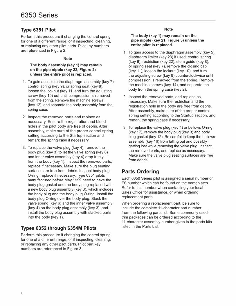
Type 6351 PilotPerform this procedure if changing the control spring for one of a different range, or if inspecting, cleaning, or replacing any other pilot parts. Pilot key numbers are referenced in Figure 2.
NoteThe body assembly (key 1) may remain on the pipe nipple (key 22, Figure 2) unless the entire pilot is replaced.
1. To gain access to the diaphragm assembly (key 7), control spring (key 9), or spring seat (key 8), loosen the locknut (key 11, and turn the adjusting screw (key 10) out until compression is removed from the spring. Remove the machine screws (key 12), and separate the body assembly from the spring case.
2. Inspect the removed parts and replace as necessary. Ensure the registration and bleed holes in the pilot body are free of debris. After assembly, make sure of the proper control spring setting according to the Startup section and remark the spring case if necessary.
3. To replace the valve plug (key 4), remove the body plug (key 3) to let the valve spring (key 6) and inner valve assembly (key 4) drop freely from the body (key 1). Inspect the removed parts, replace if necessary. Make sure the plug seating surfaces are free from debris. Inspect body plug O-ring, replace if necessary. Type 6351 pilots manufactured before May 1999 need to have the body plug gasket and the body plug replaced with a new body plug assembly (key 3), which includes the body plug and the body plug O-ring. Install the body plug O-ring over the body plug. Stack the valve spring (key 6) and the inner valve assembly (key 4) on the body plug assembly (key 3), and install the body plug assembly with stacked parts into the body (key 1).
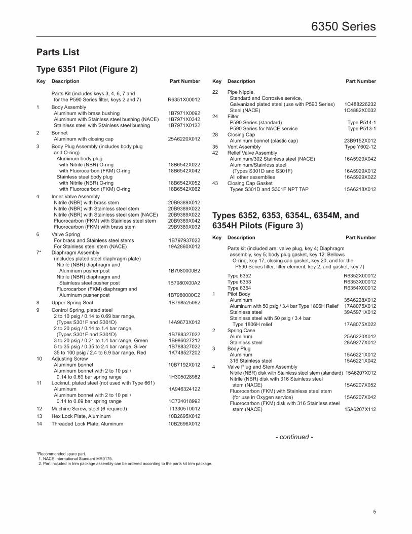
Types 6352 through 6354M PilotsPerform this procedure if changing the control spring for one of a different range, or if inspecting, cleaning, or replacing any other pilot parts. Pilot part key numbers are referenced in Figure 3.
NoteThe body (key 1) may remain on the pipe nipple (key 21, Figure 3) unless the entire pilot is replaced.
1. To gain access to the diaphragm assembly (key 5), diaphragm limiter (key 23) if used, control spring (key 6), restriction (key 22), stem guide (key 8), or spring seat (key 7), remove the closing cap (key 11), loosen the locknut (key 10), and turn the adjusting screw (key 9) counterclockwise until compression is removed from the spring. Remove the machine screws (key 14), and separate the body from the spring case (key 2).
2. Inspect the removed parts, and replace as necessary. Make sure the restriction and the registration hole in the body are free from debris. After assembly, make sure of the proper control spring setting according to the Startup section, and remark the spring case if necessary.
3. To replace the valve plug (key 4) or bellows O-ring (key 17), remove the body plug (key 3) and body plug gasket (key 12). Be careful to keep the bellows assembly (key 16) from falling out and possibly getting lost while removing the valve plug. Inspect the removed parts, and replace as necessary. Make sure the valve plug seating surfaces are free from debris.
Parts OrderingEach 6350 Series pilot is assigned a serial number or FS number which can be found on the nameplates. Refer to this number when contacting your local Sales Office for assistance, or when ordering replacement parts.When ordering a replacement part, be sure to include the complete 11-character part number from the following parts list. Some commonly used trim packages can be ordered according to the 11-character assembly number given in the parts kits listed in the Parts List.
4
6350 Series
Parts ListType 6351 Pilot (Figure 2)Key Description Part Number
Parts Kit (includes keys 3, 4, 6, 7 andfor the P590 Series filter, keys 2 and 7) R6351X00012
1 Body AssemblyAluminum with brass bushing 1B7971X0092Aluminum with Stainless steel bushing (NACE) 1B7971X0342Stainless steel with Stainless steel bushing 1B7971X0122
2 BonnetAluminum with closing cap 25A6220X012
3 Body Plug Assembly (includes body plug and O-ring)Aluminum body plugwith Nitrile (NBR) O-ring 18B6542X022with Fluorocarbon (FKM) O-ring 18B6542X042
Stainless steel body plugwith Nitrile (NBR) O-ring 18B6542X052with Fluorocarbon (FKM) O-ring 18B6542X062
4 Inner Valve AssemblyNitrile (NBR) with brass stem 20B9389X012Nitrile (NBR) with Stainless steel stem 20B9389X022Nitrile (NBR) with Stainless steel stem (NACE) 20B9389X022Fluorocarbon (FKM) with Stainless steel stem 20B9389X042Fluorocarbon (FKM) with brass stem 29B9389X032
6 Valve SpringFor brass and Stainless steel stems 1B797937022For Stainless steel stem (NACE) 19A2860X012
7* Diaphragm Assembly(includes plated steel diaphragm plate)Nitrile (NBR) diaphragm and Aluminum pusher post 1B7980000B2
Nitrile (NBR) diaphragm andStainless steel pusher post 1B7980X00A2
Fluorocarbon (FKM) diaphragm andAluminum pusher post 1B7980000C2
8 Upper Spring Seat 1B7985250629 Control Spring, plated steel
2 to 10 psig / 0.14 to 0.69 bar range, (Types S301F and S301D) 14A9673X012
2 to 20 psig / 0.14 to 1.4 bar range, (Types S301F and S301D) 1B788327022
3 to 20 psig / 0.21 to 1.4 bar range, Green 1B9860272125 to 35 psig / 0.35 to 2.4 bar range, Silver 1B78832702235 to 100 psig / 2.4 to 6.9 bar range, Red 1K748527202
10 Adjusting Screw Aluminum bonnet 10B7192X012Aluminum bonnet with 2 to 10 psi / 0.14 to 0.69 bar spring range 1H305028982
11 Locknut, plated steel (not used with Type 661)Aluminum 1A946324122Aluminum bonnet with 2 to 10 psi /0.14 to 0.69 bar spring range 1C724018992
12 Machine Screw, steel (6 required) T13305T001213 Hex Lock Plate, Aluminum 10B2695X01214 Threaded Lock Plate, Aluminum 10B2696X012
Key Description Part Number
22 Pipe Nipple,Standard and Corrosive service, Galvanized plated steel (use with P590 Series) 1C488226232Steel (NACE) 1C4882X0032
24 Filter P590 Series (standard) Type P514-1P590 Series for NACE service Type P513-1
28 Closing CapAluminum bonnet (plastic cap) 23B9152X012
35 Vent Assembly Type Y602-1242 Relief Valve Assembly
Aluminum/302 Stainless steel (NACE) 16A5929X042Aluminum/Stainless steel (Types S301D and S301F) 16A5929X012
All other assemblies 16A5929X02243 Closing Cap Gasket
Types S301D and S301F NPT TAP 15A6218X012
Types 6352, 6353, 6354L, 6354M, and 6354H Pilots (Figure 3)Key Description Part Number
Parts kit (included are: valve plug, key 4; Diaphragm assembly, key 5; body plug gasket, key 12; Bellows O-ring, key 17; closing cap gasket, key 20; and for the P590 Series filter, filter element, key 2; and gasket, key 7)
Type 6352 R6352X00012Type 6353 R6353X00012Type 6354 R6354X00012
1 Pilot BodyAluminum 35A6228X012Aluminum with 50 psig / 3.4 bar Type 1806H Relief 17A8075X012Stainless steel 39A5971X012Stainless steel with 50 psig / 3.4 barType 1806H relief 17A8075X022
2 Spring CaseAluminum 25A6220X012Stainless steel 28A9277X012
3 Body PlugAluminum 15A6221X012316 Stainless steel 15A6221X042
4 Valve Plug and Stem AssemblyNitrile (NBR) disk with Stainless steel stem (standard) 15A6207X012Nitrile (NBR) disk with 316 Stainless steel stem (NACE) 15A6207X052
Fluorocarbon (FKM) with Stainless steel stem(for use in Oxygen service) 15A6207X042
Fluorocarbon (FKM) disk with 316 Stainless steel stem (NACE) 15A6207X112
*Recommended spare part. 1. NACE International Standard MR0175. 2. Part included in trim package assembly can be ordered according to the parts kit trim package.
- continued -
5
6350 Series
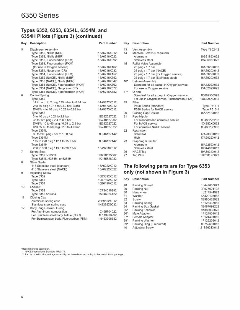
Types 6352, 6353, 6354L, 6354M, and 6354H Pilots (Figure 3) (continued) Key Description Part Number
5 Diaphragm AssemblyType 6352, Nitrile (NBR) 15A6216X012Type 6353, Nitrile (NBR) 15A6216X022Type 6353, Fluorocarbon (FKM) 15A6216X092Type 6353, Fluorocarbon (FKM)(for use in Oxygen service) 15A6216X162
Type 6354, Neoprene (CR) 15A6216X032Type 6354, Fluorocarbon (FKM) 15A6216X152Type 6352 (NACE), Nitrile (NBR) 15A6216X552Type 6353 (NACE), Nitrile (NBR) 15A6216X542Type 6353 (NACE), Fluorocarbon (FKM) 15A6216X562Type 6354 (NACE), Neoprene (CR) 15A6216X572Type 6354 (NACE), Fluorocarbon (FKM) 15A6216X582
6 Control SpringType 635214 in. w.c. to 2 psig / 35 mbar to 0.14 bar 14A9672X0122 to 10 psig / 0.14 to 0.69 bar, Black 14A9673X012DVGW 4 to 10 psig / 0.28 to 0.69 bar 14A9673X012
Type 63533 to 40 psig / 0.21 to 2.8 bar 1E39252702235 to 125 psig / 2.4 to 8.6 bar 1K748527202DVGW 10 to 40 psig / 0.69 to 2.8 bar 1E392527022DVGW 40 to 58 psig / 2.8 to 4.0 bar 1K748527022
Type 6354L85 to 200 psig / 5.9 to 13.8 bar 1L346127142
Type 6354M175 to 220 psig / 12.1 to 15.2 bar 1L346127142
Type 6354H200 to 300 psig / 13.8 to 20.7 bar 15A9258X012
7 Spring SeatType 6352 or 6353 1B798525062Type 6354L, 6354M, or 6354H 1K155828982
8 Stem Guide416 Stainless steel (standard) 15A6222X012410 Stainless steel (NACE) 15A6222X022
9 Adjusting ScrewType 6352 10B3692X012Type 6353 10B7192X012Type 6354 10B6190X012
10 LocknutType 6352 1C724018992Type 6353 or 6354 1A946324122
11 Closing CapAluminum spring case 23B9152X012Stainless steel spring case 1H2369X0032
12 Body Plug Gasket / O-ringFor Aluminum, composition 1C495704022For Stainless steel body, Nitrile (NBR) 1F113906992For Stainless steel body, Fluorocarbon (FKM) 1N463906382
Key Description Part Number
13 Vent Assembly Type Y602-1214 Machine Screw (6 required)
Aluminum 10B6189X022Stainless steel 1V4360X0022
15 Relief Valve Assembly25 psig / 1.7 bar 16A5929X05225 psig / 1.7 bar (NACE) 16A5929X04225 psig / 1.7 bar (for Oxygen service) 16A5929X03225 psig / 1.7 bar (Stainless steel) 16A5929X072
16* Bellows AssemblyStandard for all except in Oxygen service 15A6202X032For use in Oxygen service 15A6202X022
17* O-ringStandard for all except in Oxygen service 1D682506992For use in Oxygen service, Fluorocarbon (FKM) 1D6825X0012
19 FilterP590 Series (standard) Type P514-1P590 Series for NACE service Type P513-1
20 Closing Cap Gasket 15A6218X01221 Pipe Nipple
For standard and corrosive service 1C488226232For NACE service 1C4882X0032For corrosive NACE service 1C488238982
22 RestrictionStandard 17A2030X012High 17A2029X012
23 Diaphragm LimiterAluminum 15A9259X012Stainless steel 10B4407X012
26 NACE Tag 19A6034X01227 Tag Wire 1U7581X0022
The following parts are for Type 6353 only (not shown in Figure 3)Key Description Part Number
28 Packing Bonnet 1L44963507229 Packing Nut 0P07762410230 Handwheel 1L217544992 31 Washer 1A32912898232 Screw 1E98542898233 Packing Spring 1F12543701234 Packing Box Gasket 1B48709920235* Packing Follower 1K88503507236* Male Adaptor 1F12480101237* Female Adaptor 1F12440101238* Packing Washer 1F12523604239* Packing Ring (3 required) 1C75260101240 Adjusting Screw 21B5621X012
*Recommended spare part. 1. NACE International Standard MR0175. 2. Part included in trim package assembly can be ordered according to the parts kit trim package.
6
6350 Series
CB7988
34A6635-B
3
35A8889
35A6236
10
2
9
7
2224
1
12
8
11
46
42
23
3
9
20
6
22
4
16
17122119
10
7
5
8
13
11
2
14
15
1
3
23
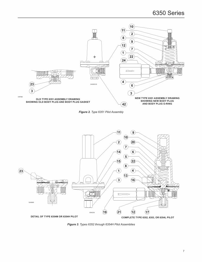
Figure 2. Type 6351 Pilot Assembly
OLD TYPE 6351 ASSEMBLY DRAWINGSHOWING OLD BODY PLUG AND BODY PLUG GASKET
NEW TYPE 6351 ASSEMBLY DRAWINGSHOWING NEW BODY PLUG
AND BODY PLUG O-RING
DETAIL OF TYPE 6354M OR 6354H PILOT
Figure 3. Types 6352 through 6354H Pilot Assemblies
COMPLETE TYPE 6352, 6353, OR 6354L PILOT
7
6350 Series
D103153X012 © 2008, 2019 Emerson Process Management Regulator Technologies, Inc. All rights reserved. 07/19. The Emerson logo is a trademark and service mark of Emerson Electric Co. All other marks are the property of their prospective owners. Fisher™ is a mark owned by Fisher Controls International LLC, a business of Emerson Automation Solutions.
The contents of this publication are presented for informational purposes only, and while every effort has been made to ensure their accuracy, they are not to be construed as warranties or guarantees, express or implied, regarding the products or services described herein or their use or applicability. All sales are governed by our terms and conditions, which are available upon request. We reserve the right to modify or improve the designs or specifications of such products at any time without notice.
Emerson Process Management Regulator Technologies, Inc does not assume responsibility for the selection, use or maintenance of any product. Responsibility for proper selection, use and maintenance of any Emerson Process Management Regulator Technologies, Inc. product remains solely with the purchaser.
6350 Series
Facebook.com/EmersonAutomationSolutions
LinkedIn.com/company/emerson-automation-solutions
Twitter.com/emr_automation
Fisher.com
Emerson Automation Solutions
Americas McKinney, Texas 75070 USA T +1 800 558 5853
+1 972 548 3574
Europe Bologna 40013, Italy T +39 051 419 0611
Asia Pacific Singapore 128461, Singapore T +65 6777 8211
Middle East and Africa Dubai, United Arab Emirates T +971 4 811 8100


![[A PILOTS PERSPECTIVE OF THE 1989 PILOTS DISPUTE ]apaterson/aviation/1989_pilot_dispute.pdf · flight.org Alex Paterson | . [A PILOTS PERSPECTIVE OF THE 1989 PILOTS DISPUTE ] ALEX](https://img.pdfslide.net/doc/110x75/5ad4c90f7f8b9aff228c436f/a-pilots-perspective-of-the-1989-pilots-dispute-apatersonaviation1989pilotdisputepdfflightorg.jpg)