Embed Size (px)
Citation preview

��������
������������������������������������� ������ ������ ������ �����
������������
��������� ������������ ������������ ������������ �����������
����� ������������������ ������������������ ������������������ ���������������������������������������������
����
����������������

�������� �� ���������� �� ���������� �� ���������� �� ����������
1. DISASSEMBLY AND REPLACEMENT (#1~ #22)
2. PARTS LIST
3. P.C.B. CIRCUIT DIAGRAM
4. C.P.U BLOCK DIAGRAM AND PIN ASSIGNMENT
5. MEASUREMENT
• VOLTAGE CHECK
• MOTOR OPERATION CHECK
• PRINT HEAD RESISTANCE MEASUREMENT
• SENSORS CIRCUIT
• CPU OPERATION
DISASSEMBLY AND REPLACEMNET 1
1. Remove front case.
2. Replace quartzose clock.
3. Replace Ribbon.
4. Remove Print Head.
5. Replace Fuse.
6. Remove back case.
7. Remove operation Panel block.
8. Remove the LCD.
9. Remove the Ribbon Drive Shaft.
10. Removing to LF reduction gears, mid gear and roller gear.
11. Removing the paper feed shaft and bearings.
12. Remove the cam gear, reduction gear, change gear and gear guide.
13. Remove the ribbon cam.
14. Remove the lead screw assembles, platen bearings and lead screw top.
15. Removing the card inlet and spacer and E-03&E-05 the sensor.
16. Removing the E-37 sensor.
17. Removing the E-30 sensor.
18. Removing the E-38 sensor.
19. Removing the switch lever and switch lever.
20. Remove the friction spring, friction shaft and friction roller.
21. Remove 2000UL PCB assembly.
22. Load NiCd battery.

1 Remove front case
1-1 1-2
1-3
1.Remove two screws M3 8
2.Two press place and push out direction
3. Remove front case

2. Replace quartzose Clock
2-1 2-2
2-3 2-4
2-5 2-6

2-7 2-8
2-9 2-10
1.Remmove one screw ST3 7 (2-1)
2.Remove active cover(2-2 2-3 2-4)
3.Remove time face Acryl 2-5
4.Remove second hand 2-6
5.Remove minute hand 2-7
6.Remove hour hand 2-8
7.Remove one screw 2-9
8.Remove quartzose clock 2-10
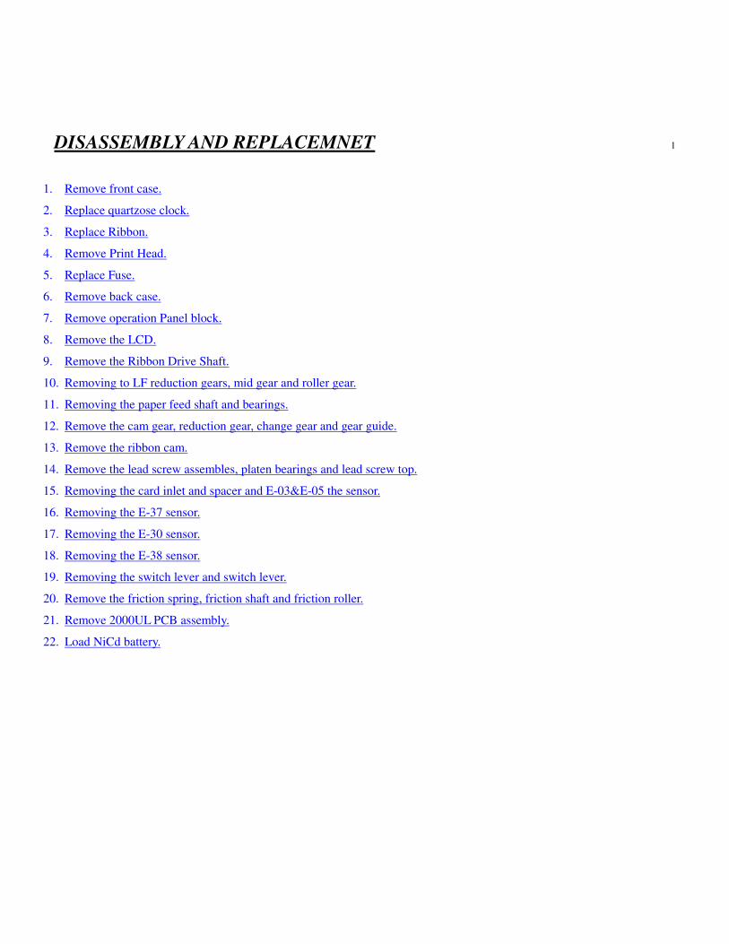
3. Replace Ribbon
3-1 3-2
3-3 3-4
1. Remove and discard two pin clip. 3-1 3-2
2. Pull the ribbon cassette by hand. 3-3 3-4
3. Load new Ribbon
4. Load two pin and clip and front case.
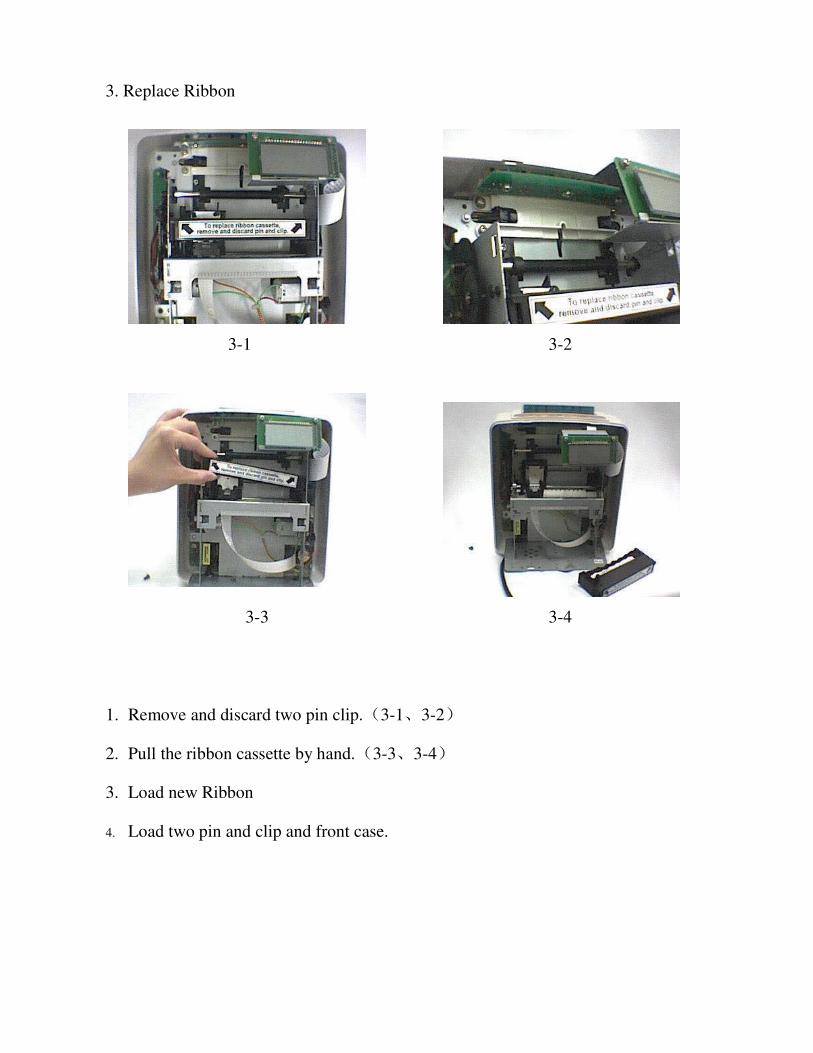
4. Remove Print Head
4-1 4-2
4-3 4-4
4-5 4-6

1.Remove the FPC guide using a standard type screwdriver.(4-2)
2.Disconnect the FPC cable from the connector (PCN8).(4-3 4-4)
3.Pull the head toward the front by hand. 4-5
4.Left it to remove. 4-6

5. Replace Fuse
5-1 5-2
5-3 5-4
1.Remove one screw M3 6(5-1)
2.Open the small back cover(5-2)
3.Remove the damage fuse(5-3)
4.Replace a new fuse into right place
5.Close the small back cover and install the screw(5-4)

6. Remove back case
6-1 6-2
6-3 6-4
1.Remove four screws M4 10(6-2)
2.Remove the back case by hand and disconnect operation panel block cable from
the connector on operation panel block.(6-3 6-4)

7. Remove operation Panel block 7-1
7-1 7-2
7-3
1.Remove three screws ST3 7 7-2
2.Remove the operation panel block 7-3

8. Remove the LCD
8-1 8-2
8-3
1.Disconnect the LCD cable from the connector (LCN10) on the 2000UL PCB
assembly.(8-1)
2.Disconnect the LCD cable from the connector on the 2003A PCB assembly.(8-1)
3.Remove two screws.(8-2)
4.Remove the LCD.(8-3)

9. Remove the Ribbon Drive Shaft
9-1 9-2
9-3 9-4
1.Remove the screw fixing the Ribbon Clutch Holding Plate. 9-2
2.Remove the Ribbon Drive shaft by hand.(9-3)

10. Removing to LF reduction gears, mid gear and roller gear
10-1 10-2
10-3 10-4
1.Remove three snap rings with a standard type screwdriver.(10-3)
2.Pullthe two LF reduction gears out of the shaft (Inset a standard type screwdriver
into the gap between the LF gear and frame, and lift the gear).(10-4)
3.Remove the mid gear in the same manner as shown second step.
4.Remove the roller gear in the same manner as shown second step.

11. Removing the paper feed shaft and bearings
11-1 11-2
11-3 11-4
11-5 11-6

1.Removing the LF Reduction gear.(11-1)
2.Removing the Roller gear.(11-2)
3.Turn the bearing with small pliers to match up the projections on the bearing with
the notches in the frame.(11-3)
4.Remove the bearings from the paper feed shaft to outside of the frame (There are
two bearings, on the right and left).(11-4)
5.More the paper feed shaft by hand.(11-5)
6.Detach it toward the front from inside the frame.(11-6)

12. Remove the cam gear, reduction gear, change gear and gear guide
12-1 12-2
12-3 12-4
1.Remove the motor gear.(12-1)
2.Remove one screw to remove the Lever Holding Spring(12-2)
3.Pull the cam gear out of the shaft , Inset a standard type screwdriver into the gap
between the cam gear and frame, and left the cam gear. Be careful mot to press the
screwdriver against the shaft from the side.
4.Remove the reduction gear in the same as shown in above step. The change gear
and gear guide are also remove with the reduction gear.
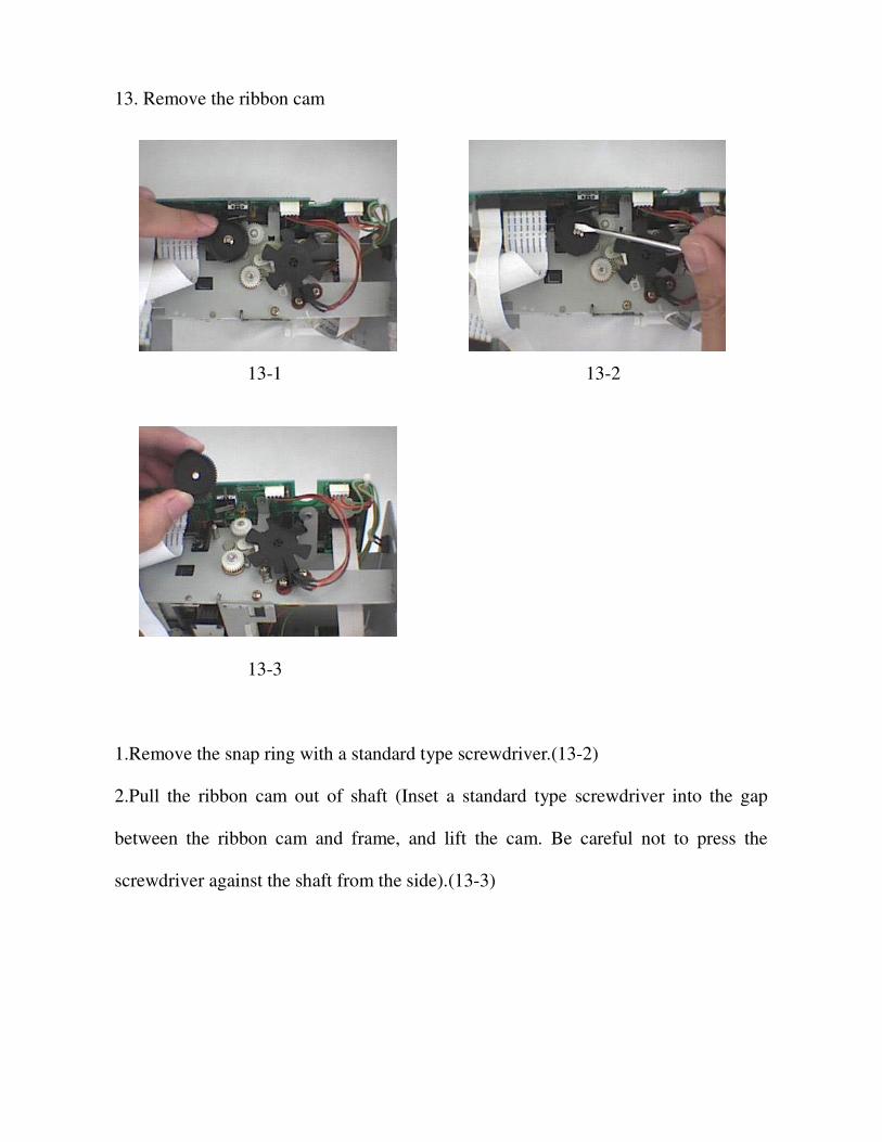
13. Remove the ribbon cam
13-1 13-2
13-3
1.Remove the snap ring with a standard type screwdriver.(13-2)
2.Pull the ribbon cam out of shaft (Inset a standard type screwdriver into the gap
between the ribbon cam and frame, and lift the cam. Be careful not to press the
screwdriver against the shaft from the side).(13-3)

14. Remove the lead screw assemble, platen bearings and lead screw top
14-1 14-2
14-3 14-4
14-5 14-6

14-7 14-8
14-9 14-10
14-11
14-12

14-13
1.Remove one screws.(14-3)
2. Remove platen bearing whirl stop screw from the right.(14-4 14-5)
3.Remove the LF gear and the motor gear and two screws to pull out the motor
A.(14-6 14-7 14-8 14-9)
3.Remove the lead screw assemble by hand.(14-10 14-11)
4.Turn the lead screw top to match up the projection on it with the notch in the carrier.
Pull the lead screw top below the carrier. 14-12 14-13

15. Removing the card inlet and spacer and E-0305 the sensor
20-1 20-2
20-3 20-4
20-5 20-6

20-7
Remove four screws fixing the card inlet.(20-1)
1. Remove the card inlet by hand.(20-2 20-3)
2. Press the hooks of the right and left sensors slightly outwards and pull out the
E-0305 sensors. Be careful not to break the hooks.(20-4 20-5)
3. Remove two screws fixing the spacer and pull out the spacer.(20-6 20-7)

16. Removing the E-37 sensor
21-1 21-2
21-3 21-4
1.Remove two screws to take out of the sensor holding plate.(21-1 21-2)
2.Remove another two screws to take out the sensor.(21-3 21-4)
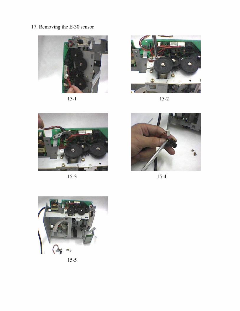
17. Removing the E-30 sensor
15-1 15-2
15-3 15-4
15-5

1.Disconnect the sensor harness assembly from the connector(LCN3)on the 2000UL
PCB assembly.(15-1)
2.Remove two screws to take out the screw holding plate.(15-2 15-3)
3.Remove another two screws to take out the sensor.(15-4 150-5)

18. Removing the E-38 Sensor
16-1 16-2
2
2
16-3 16-4
1.Dissconnect the sensor harness assembly from the connector(LCN9)on the 2000UL
PCB assembly.
2.Remove two screws(M3 8) to take out the sensor.
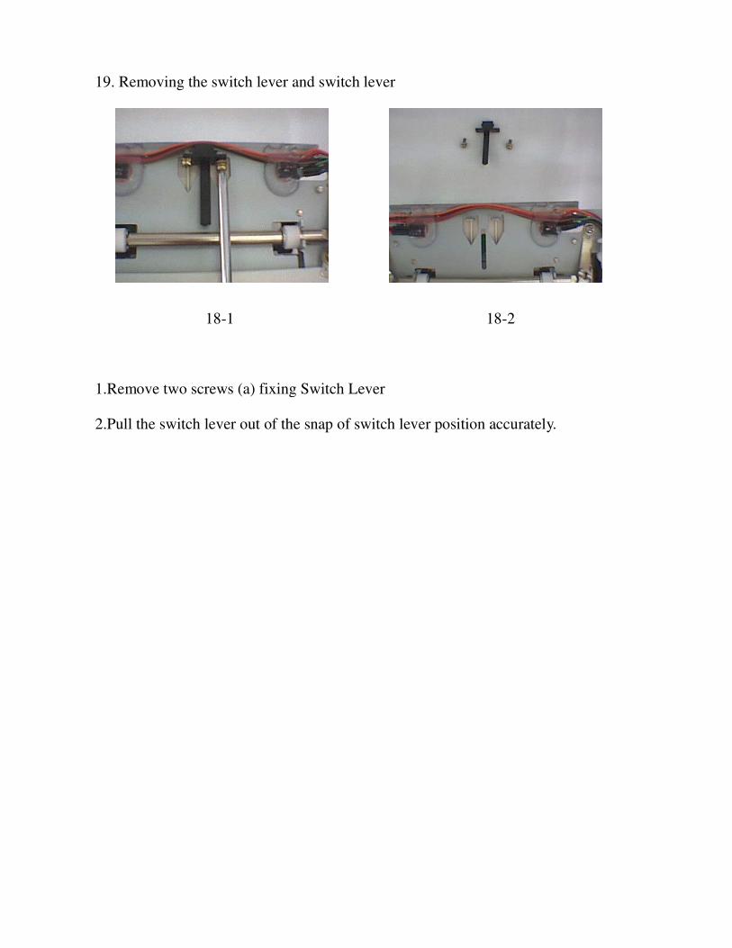
19. Removing the switch lever and switch lever
18-1 18-2
1.Remove two screws (a) fixing Switch Lever
2.Pull the switch lever out of the snap of switch lever position accurately.

20. Remove the friction spring, friction shaft and friction roller
19-1 19-2
19-3 19-4
19-5

1. Remove two screws fixing the right and left friction springs to remove the friction
springs. The friction shaft and friction roller are also removed.

21. Remove 2000UL PCB assembly
17-1 17-2
17-3 17-4
17-5 17-6

17-7
1.Disconnect all the sensor harness assembly, and LCD cable, and operation black
cable, and motor block, and FPC cable from the connectors on the 2000UL PCB
assembly 17-1 17-2
2.Remove two screws 17-3
3.Pull out the 2000UL PCB assembly by hand 17-4
4.Solder down the power supply wire to pull out the 2000UL PCB assembly. 17-5
17-6 17-7

22. Load NiCd battery
22-1 22-2
22-3 22-4
22-5 22-6

22-7 22-8
1. Place black sticker on the main body shelf.
2. Place white both sided sticker on the rechargeable battery.
3. Place rechargeable battery on the main body shelf.
4. Tighten the battery.
5. Tighten the inside wires.

PARTS LIST
Acroprint ATR120 Time recorder BOM
THE ELECTRON COMPONENT
Name Mode Place In ATR120 P/N Remarks
Multilayer CeramicCapacitor 0.1uF/50V PC21 PC22 PC14
Multilayer CeramicCapacitor 0.01uF/50V PC10 LC25 LC38
Multilayer CeramicCapacitor 1000PF/50V PC8 PC18 LC29 LC30 LC36
Multilayer CeramicCapacitor 100PF/50V LC26 LC28 LC37 LC39 LC40
LC41 LC42 LC43Ceramic Capacitor 0.1uF/50V PC19 PC23Multilayer CeramicCapacitor 18P/50V 5% LC33
Multilayer CeramicCapacitor 15PF/50V 5% LC34
Multilayer CeramicCapacitor 30PF/50V 5% LC31 LC32
Diode IN4007 PD2 PD3 PD4 PD5 PD6PD7 PD8 PD11 SD3
Diode IN4148 LD11 LD12 LD13 PD9
16K 1/4W 1% PR13
18K 1/4W 1% LR39
1 M 1/4W 1% LR26
4.7K 1/4W 1% PR14
100K 1/4W 5% LR19 LR41 LR42 LR76
10K 1/4W 5% LR27 LR32 LR33 LR47 LR49LR68 BR77
10R 1/4W 5% PR7
15K 1/4W 5% LR20 LR22 LR24 LR28 LR30LR70
1 K 1/4W 5%
PR2 LR45 LR46 LR48 LR50LR52 LR53 LR54 LR55 LR56LR57 LR58 LR59 LR60 LR61LR62 LR63 LR64 LR65 LR66LR67
2.2K 1/4W 5% PR11 PR15 LR21 LR23 LR25LR29 LR31 LR69
22R 1/4W 5% PR3

Name Mode Place In ATR120 P/N Remarks
270K 1/4W 5% LR18
33K 1/4W 5% PR9 PR10
620R 1/4W 5% LR37 LR38 LR44 LR51 LR71
820R 1/4W 5% PR8
9.1K 1/4W 5% LR40 LR72 LR73 LR74
D1866 Q5 Q6 Q7 Q8 Q9 Q10 Q11 Q12Q13
2000UL PCB
IC UC3842BN PU1
Opto-couple PC817 PU3
SCR TL431 PU2
IC TA7291 PU10 PU11
IC 78L05 PU4
IC 74HD404889 LU5 PN NBE-065
IC HD74HC14P LU6
IC HD74HC244P LU8 LU9
IC UL·N2003 LU7
MOSFET K2608 PQ1
Bridge-commuted KBL206 PD1
Dynatron C1815 Q3 Q4 Q15 Q17 BQ20
Dynatron C1015 Q18 Q19
X2 Capacitor 0.1UF/275V PC3
X2 Capacitor 0.33UF/275V PC1
Ceramic Disc Capacitor PC24Polyester Film Capacitor 0.047UF/100V PC9
Aluminum ElectrolyticCapacitor 1UF/50V PC12
Aluminum ElectrolyticCapacitor 10UF/16V LC35
Aluminum ElectrolyticCapacitor 47UF/25V PC7 PC16 PC17
Aluminum ElectrolyticCapacitor 100UF/25V PC15
Aluminum ElectrolyticCapacitor 1000UF/25V PC11

Name Mode Place In ATR120 P/N Remarks
Aluminum ElectrolyticCapacitor PC13
Aluminum ElectrolyticCapacitor PC1
Neilsbed 2PIN 180° PCN1
Neilsbed 4PIN 180° LCN3 LCN4 LCN8 PCN9
Neilsbed 4PIN 90° LCN0
Neilsbed 8PIN 90 LCN5
Flex. PCB Socket 10PIN 180° LCN12
Flex. PCB Socket 12PIN 180° PCN7
Flex. PCB Socket 21PIN 180° LCN10
100R 1W 5 PR16
270R 1W 5 PR12
360R 1W 5 LR35 LR36-1
0.5R 2W 5 PR1
51K 2W 5 PR5
270K 2W 5 PR6
Buzzer KC-1201 BZ1
Buzzer XHD RL1
Crystal 32.768KHZ LX1
Crystal 4.00MHZ LX2
CR2032 PBT1
Fuse DC12V 2A PF3
Fuse DC12V 1.5A PF1
Fuse AC240V 1A PF2
Fuse nip
Line Filter UU9.8 30mH PLF1
Filter 47uH
Choke Coil 15uH
Choke Coil 1.5A 48mH PL1
Transformer EI-28 PT1
Tact Switch TS1102P RESET
Mechanical switch SW/3P SW301 SW302
Switch SW/3P SW304

Radiating-flake Model E
Flame Assembly P/N NBD-980101
Plate Soleplate P/N NBD-980118
Switch Lever P/N NB-008
Switch Lever B P/N NB-015
Switch Lever Support P/N NB-019
Paper Feed Shaft P/N NBD-980108
Friction ShaftP/NNBD-980109
Friction Roller P/N NB-034
Friction Spring P/N NBD-980121
Lever Holding Spring 0.4mm P/N NBD-980113A
Lever Holding Spring 0.2mm P/N NBD-980113B
Guide Pillar P/N NBD-990107
Platen Bearing P/N NBL-980100
P/N NB-048
Carrier P/N NB-002
Lead Screw Top P/N TW102
Platen P/N NBD-980108
FPC Guide P/N NBD-980117
Print Head P/N YZCP-100
Cassette Holding Plate R P/N NB-006
Ribbon Cam Spring P/N NBD-980125
Ribbon Drive Shaft P/N NB-005
Ribbon Clutch Gear P/N NB-028
Ribbon Clutch Spring P/N NBD-980126
Ribbon Clutch HoldingPlate P/N NBD-980106
Carrier Auxiliary Board P/N NB-037
Reduction Gear P/N NB-029
Chang Gear P/N NB-032
Gear Guide P/N NB-037
Roller Gear P/N NB-003
Mid Gear P/N NB-004
LF Reduction(A) P/N NB-017
LF Reduction(B) P/N NB-039
Motor Gear P/N NB-035
Motor Gear P/N NB-011
Cam Gear P/N NB-033
Lead Screw Gear P/N NB-027
Ribbon Cam P/N NB-013/014
Card Guide(Left) P/N NB-009
Card Guide(Right) P/N NB-010
Card Inlet P/N NB-040
Bearing big P/N NB-018
Bearing small P/N NB-019
Motor(A) P/N TW-104
Motor(B) P/N TW-105
Motor Holding Plate P/N NBD-980105
Motor Block P/N NBE-090
E-03 05Sensor SG-205 P/N NBE-091
E-30 Sensor SG-23FF P/N NBE-092
E-37 38Sensor SG-289 P/N NBE-093
Sensor Signal Wire
Sensor Signal Wire
Tubing
Sensor Holding Plate E-30 Sensor P/N NDB-980114
Sensor Holding Plate E-37 Sensor P/N NDB-980115
Power Supply Wire P/N NBE-094
Insulating Bushings 5P-4 P/N NBE-095
Insulating Bushings 3F-2 P/N NBE-096
LCD P/N CDCP-062
LCD Holding Plate P/N NBD-980104
LCD Cable 170mm P/N NBE-097
Operation Panel Block P/N AJCP-064
Operation Panel BlockCable P/N NBE-098
Cushion(#1) 5.0×3.10×0.13 P/N DP-109
Cushion(#2) 9.0×6.35×0.13 P/N DP-110
Cushion(#3) 9.0×6.35×0.26 P/N DP-111
Cushion(#4) 9.0×6.35×0.50 P/N DP-112

Cushion(#5) 8.5×4.05×0.30 P/N DP-113
Red Cushion 1.0mm P/N DP-114
Red Cushion 1.6mm P/N DP-115
Snap Rings P/N DC-116
Snap Rings P/N ZC-117
Snap Rings P/N XC-118
Screws P/N NB-119
Screws P/N NB-120
Screws P/N NB-121
Screws M3 8 Phillips round head screws with SpringWasher
P/N NB-122
Screws M3 8 Phillips round head screws with SPW P/N NB-123
Screws P/N NB-124
Screws P/N NB-125
Screws M4×10Phillips round head screws P/N NB-126
Screws M4×8 Phillips round head screws with SPWs P/N NB-127
Screws ST4 19 P/N NB-128
Snap rings NDB-980124
Nut M3 P/N NB-129
Nut M4 P/N NB-130
ABS765A P/N NB-044
ABS765A P/N NB-001
Explain Label P/N NB-131
Dust Cover ABS765A P/N NB-021
Keyboard film P/N NB-132
Front Case ABS765A P/N NB-045/049/046
Active Cover ABS765A P/N NB-042
Time Face Acryl P/N NB-043
Small Acryl P/N NB-041
Clock P/N NB-052
Rubber Cushion P/N NB-053
Cuprum Cushion P/N NB-054
Nut P/N NB-055
Hour Hand white ATR120 P/N NB-056
Minute Hand white ATR120 P/N NB-057

Second Hand white ATR120 P/N NB-058
Clock face AluminumBoard P/N NB-059
Cell 1.5V P/N NB-133
button P/N TW-107
Ribbon SDCP-101
Underlay P/N NB-060
Pin and Clip P/N TW-108
Label P/N NB-136
P/N NB-137
Notebook ATR120 P/N NB-138
Wall Map P/N NB-139
8# Bag 250×180 P/N NB-140
0# Bag 70×50 P/N NB-141
Bag 450×360 P/N NB-142
Fix up Holding Plate P/N NBD-980107
Plastic Thimble P/N NB-143
battery 3V P/N NB-134
Carton ATR121 P/N NB-144
Carton ATR121 P/N NB-145
P/N NB-146
Time Card P/N NB-147
Serial Label P/N NB-148
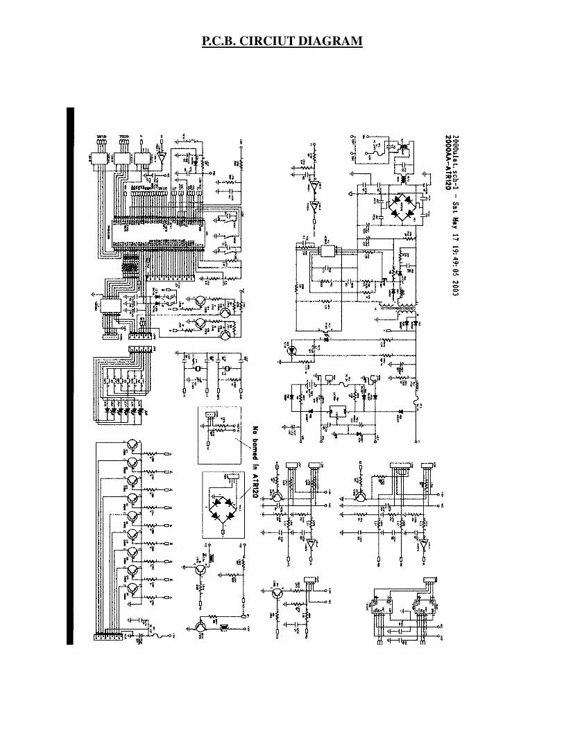
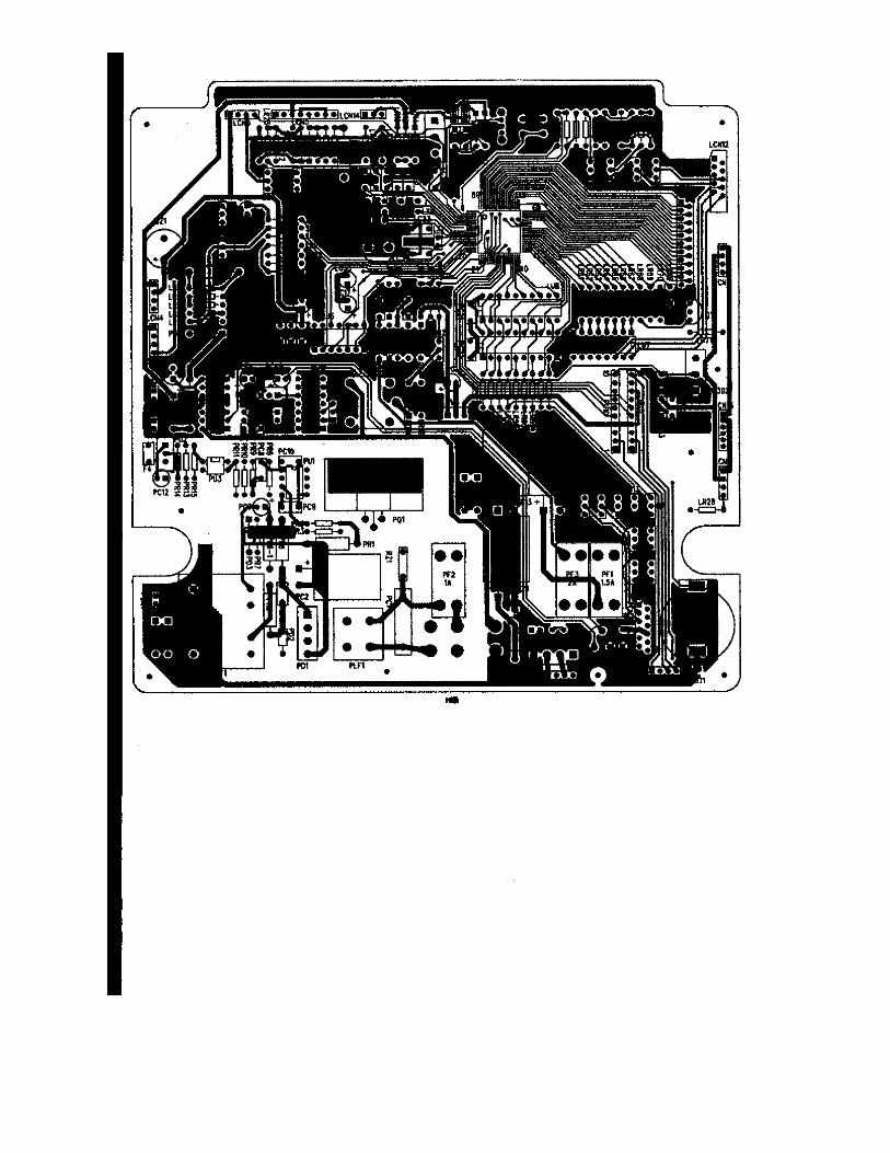
P.C.B. CIRCIUT DIAGRAM

BELOW:TOP LAYER
BOTTOM LAYER
BOTTOM LAYOUT
TOP LAYOUT


C.P.U BLOCK DIAGRAM AND PIN ASSIGNMENT
<PORT LIST>74HD404889port Name Function Description Logic
2 R70/AN0 IN NiCd battery change control signal3 R71 IN Mechanical switches L4 R72 IN Red/Black ribbon check switch L5 R73 IN Head position check sensor(E-30) L6 R80 IN Card right/back side check sensor H7 R81 IN Card right/back side check sensor H
17 D0/INT0 IN Head feed encoder sensor input(E-38)18 D1/INT1 IN Paper feed encoder sensor input(E-37)19 D2 OUT H20 D3 OUT Five sensors control H21 D4 IN AC Failure detection signal H22 D5 IN 5V monitoring H23 D6 OUT Time signal control H
24~26 D7~D9 OUT Six key and jumper wire scan control L27~28 D10~D11 OUT Six LED scan control L
29 R00 OUT Paper feed motor control(Pulling) H30 R01 OUT Paper feed motor control(Ejection) H31 R02 OUT Head feed motor control(Changing red and black ribbons) H32 R03 OUT Head feed motor control(Head feed) H33 R10 IN red or black ribbons control L34 R11/EVND No use35 R12/BUZZ OUT Piezoelectric buzzer control36 R13 OUT Printer head pin1 H37 R20 OUT Printer head pin2 H38 R21 OUT Printer head pin3 H39 R22 OUT Printer head pin4 H40 R23 OUT Printer head pin5 H41 R30 OUT Printer head pin6 H42 R31 OUT Printer head pin7 H43 R32 OUT Printer head pin8 H44 R33 OUT Printer head pin9 H
45~48 R40~R43 OUT Step motor control49~51 R50~R52 OUT Six LED SEG control H
52 R53 OUT Clock sensor control H53~55 R60~R62 IN Six key and jumper wire control L
56 R63 IN Clock sensor input H57~72 SEG17~SEG32 OUT LCD display SEG73~76 COM1~COM4 OUT LCD display COM

<ELECTRONIC TIME RECORDER CONTROL PANE >
Electronic Time Recorder Control Pane
CPUHD40489B33H
74HC244
Q5~13
PrinterPCN7
LCD (LCN10)
KEY1~6
ULN2003
LED1~6
SW301
SW30
TA7291P
MOTOR (PCN8)A and B
SW30
Q4
Buzzer1BQ2
Buzzer2DC12V
OCS2 (32.768 KHz)
OCS1 (4MHz)
Q2E-0305(LCN
E-37(LCN
Q3
E-30(LCN3)
E-38(LCN


MEASUREMENT1 Voltage check
Measuring point Voltage Description11V�GND 11.0V 5% AC plug should be connected5V�GND 5.0V 5% AC plug should be connected
Note: Measurement with no load is possible.
2 Motor operation check (PCN8.1~4)Apply the voltages shown below to the terminals of the harness connected to connector PCN8 on the 2000UL PCB ass’y to make surethat the motor runs properly.
Applied voltageMotor OperationPin 1(orange) Pin 2(green) Pin 3(red) Pin 4(green)
LF Motor(A motor) Pulling 4~9V GND ----- -----LF Motor(A motor) Ejection GND 4~9V ----- -----
CR Motor(B motor) Changing red and blackribbons.(Continuous) ----- ----- 4~9V GND
CR Motor(B motor) Head feed ----- ----- GND 4~9V
3 Head resistance measurement (PCN7.1~12)Measure the head resistance at the terminals of the harness connected to connector PCN7 on the 2000UL PCB ass’y.
Measuring point(PIN NO. of PCN7) Resistances1 82 83 84 85 86 87 89 8
10 811 812 8
Open3.03.03.03.03.0
Short3.03.03.03.0
Note If the head resistance is less then the values shown above the head pin drive circuit may also be defective Replace the head andrepair the 2000UL PCB ass’y.
4 Sensors circuitThere are five sensors their functions are show below:
Name CPU port FunctionsE-03 R80 Detects the right-up edge of an inserted time card.E-05 R81 Detects the left-up edge of an inserted time card.E-37 D1 Detects the operating condition of the LF motor.E-38 D0 Detects the operating condition of the CR motor.E-30 R73 Check whether the head is at the home position(left end of the machine).

(LCN5.1~8)DescriptionMeasuring point (Pin NO.) Signal name
Stand by Inserted time card and printing1 E-03-E 0 0 4.0V or more 02 E-03-C 5V 5V3 E-03-A 10.2V or more 10.0V or more4 E-03-K 9.5V or more 8.5V or more5 E-05-E 0 0 4.0V or more 06 E-05-C 5V 5V7 E-05-A 9.5V or more 8.5V nor more8 E-05-K 9.0V or more 7.5V or more
E-37 sensor (LCN4.1~4)DescriptionMeasuring point (Pin NO.) Signal name
Stand by Inserted time card and printing10.2V or more 10.0V or more
9.5V or more 8.5V or more
E-38 sensor (LCN9.1~4)DescriptionMeasuring point (Pin NO.) Signal name
Stand by Inserted time card and printing10.2V or more 10.0V or more
9.5V or more 8.5V or more
E-30 sensor (LCN3.1~4)DescriptionMeasuring point (Pin NO.) Signal name
Stand by Inserted time card and printing10.2V or more 10.0V or more
9.5V or more 8.5V or more4.0V or more 0 4.0V or more 0
or0 4.0V or more 0

The following table shows the operation modes and functions:
Mode A B C D
Operation
Normaloperation.. Allfunctions arevalid.
Power failure modewhere printing ispossible Same operationas in A mode.
Power failure mode.Time is updated. Datais saved in the memory.
Power failure mode.Time is updated. Datais saved in the memory.
AC powersupply
ON OFF OFF OFF
Printingbattery
Operable/dead Operable(guaranteesmechanism operation)
Operable(does notguarantees mechanismoperation)
Dead. Or, operable butsupplies voltage belowthe rated value.
Backlight(LED)
Yes NO NO NO
Batteryindicator
No display Full to half Should be replace.(flashes)
NO
CPU statusActive mode
�Watch mode
Active mode�
Watch mode
Active mode�
Watch modeWatch mode
<CONNECTOR PIN ASSIGHMENT>2000UL PCB Ass’y(1) PCN1
Pin No. Signal name
1 NiCd Battery Output
2 GND
(2) LCN3
Pin No. Signal name
1
2
3
4
(3)LCN4
Pin No. Signal name
1
2
3
4

(4)LCN9
Pin No. Signal name
1
2
3
4
(5)LCN0
Pin No. Signal name
1 +5V
2 GND
3 Card insertion
4 Panel open/close
(6)LCN5
Pin No. Signal name Pin No. Signal name
1 E-03-E 5 E-05-E
2 E-03-C 6 E-05-C
3 E-03-A 7 E-05-C
4 E-03-K 8 E-05-K
(7)LCN12
Pin No. Signal name Pin No. Signal name
1 R60 6 D9
2 R61 7 D10
3 R62 8 R50
4 D7 9 R51
5 D8 10 R52
(8)LCN10
Pin No. Signal name Pin No. Signal name
1 SEG17 12 SEG28
2 SEG18 13 SEG29
3 SEG19 14 SEG30
4 SEG20 15 SEG31
5 SEG21 16 SEG32
6 SEG22 17 COM1
7 SEG23 18 COM2
8 SEG24 19 COM3
9 SEG25 20 COM4
10 SEG26 21 No use
11 SEG27

(9)PCN8
Pin No. Signal name
1 R00(A motor)
2 R01(A motor)
3 R02(B motor)
4 R03(B motor)
(10).PCN7
Pin No Signal name. Pin No Signal name
1 GND 7 11V
2 PIN4 8 11V
3 PIN6 9 PIN3
4 PIN2 10 PIN9
5 PIN8 11 PIN5
6 PIN1 12 PIN7


![EIP Final 2 CCUS DRAFT - Oil and Gas Authority...&&6 SRWHQWLDO IRU QHW ]HUR &DUERQ FDSWXUH DQG VWRUDJH &&6 LV OLNHO\ WR SOD\ D VLJQLILFDQW UROH IRU 8. V QHW ]HUR %(,6 HVWLPDWHG FD](https://img.pdfslide.net/doc/110x75/60d916e341186e6dfd1bf224/eip-final-2-ccus-draft-oil-and-gas-authority-6-srwhqwldo-iru-qhw.jpg)