Embed Size (px)
Citation preview

twoand
rtly
d a
iece
be
illsg. 1.tenerye a
tivesidetingandero
CIRP Annals - Manufacturing Technology 61 (2012) 83–86
lling
for
heir
dge
ond,
rate
IRP.
Manufacture and application of ultra-small micro end mills
Jan C. Aurich (1)*, Ingo G. Reichenbach, Guido M. Schuler
Institute for Manufacturing Technology and Production Systems, University of Kaiserslautern, Germany
1. Introduction
The demand for micro products and related componentsincreases rapidly along with possible applications in optical,mechanical, electrical, medical, and biochemical devices. There-fore, micro manufacturing processes are a fast-evolving area ofresearch. Micro end milling provides the advantage of a relativelyhigh material removal rate and at the same time allows for themanufacture of complex three dimensional structures.
Micro end milling is a highly flexible manufacturing process. Itis for example used to machine small features in molds used formass production, to structure medical implants for betterbiocompatibility, to generate deep X-ray lithography masks, andto manufacture microfluidic devices [1,2]. Different from alter-native manufacturing processes, it is even possible to manufactureundercuts by using profiled milling tools [3]. The quality of themicro machined parts depends on the cutting parameters, themilling strategy, the work piece material, and to a large extend onthe micro end milling tool itself [4–6]. The tool may vary inmaterial, overall geometry, cutting edge radius, surface conditionsand coating. The tool design influences dimensional accuracy,surface quality, burr formation, and tool life [7]. Therefore, it is ofhigh importance for micro end milling.
Several researchers have reported the development of microend mills with various geometries and tool manufacturingprocesses. Vasile [8] used a focused ion beam to manufacturemicro end mills with 25 mm diameter. Schaller [9] described agrinding process to manufacture micro end mills with 50 mmdiameter whereas Egashira [10] reported the use of electricaldischarge machining to produce micro ball end mills with 10 mm
grinding, and the application of these micro end mills in
different material classes, a titanium alloy (Ti–6Al–7Nb)
polymethyl methacrylate (PMMA), are described.
2. Manufacture of micro end mills
2.1. Tool design
A good end mill tool design needs to fulfill various, paconflicting, specifications and requirements. The tool must:
– allow for good chip formation and removal,– have a sharp cutting edge leading to a low cutting force an
small minimal undeformed chip thickness,– have a flank geometry which prohibits contact to the workp
at the side walls, and– be manufactured by a robust and fast process in order to
economically feasible.
The main geometrical characteristics of the micro end mwhich have been developed during this study can be seen in FiThe overall choice is to use single-edge mills made of tungscarbide. They are well-suited to meet the specifications at vsmall diameters and at the same time can be used to machinlarge variety of materials.
The radii of the radial flank face are smaller than the effeccutting radius (R) to avoid contact between the tool and the
walls of the workpiece during cutting. A positive minor cutedge angle (xr
0) prohibits unwanted contact between the tool
the bottom surface. The cross-section with its oval profile and z
A R T I C L E I N F O
Keywords:
Milling
Micromachining
Cutting tool
A B S T R A C T
The use of micro parts and micro structured elements has constantly grown over the past decade. Mi
with micro end-mills belongs to the manufacturing technologies which offer a high potential
competitive micro machining. However, the design criteria for the micro end-mills and t
manufacture pose many challenges. In this paper, first the design and manufacture of single-e
micro end-mills with diameters between 10 and 50 mm and a variable helix angle is described. Sec
the use of these end-mills in titanium and polymethyl methacrylate (PMMA) is described to demonst
their potential.
� 2012 C
Contents lists available at SciVerse ScienceDirect
CIRP Annals - Manufacturing Technology
journal homepage: http: / /ees.elsevier.com/cirp/default .asp
theongfaceore,
radius. Goto [11] describes CBN micro end mills with 30 mmdiameter and their performance.
In this paper, a geometrically optimized tool design, themanufacture of micro end mills with diameters down to 10 mm by
ressting* Corresponding author.
E-mail address: [email protected] (J.C. Aurich).
0007-8506/$ – see front matter � 2012 CIRP.
http://dx.doi.org/10.1016/j.cirp.2012.03.012
axial and radial rake angles (g) are distinct characteristics oftools. Without a helix angle, material removal occurs at once althe entire cutting length lc, with high stress areas, poor surquality, burrs, and increased tool wear as result. Therefwhenever possible helical tools are used.
Fig. 2 shows the total deformation and the total stwith varying helix angles and otherwise identical cutconditions.

Fplacorthcuttboddistrmacbrittalsoflute
J.C. Aurich et al. / CIRP Annals - Manufacturing Technology 61 (2012) 83–8684
or the calculations, the cutting force vector (0.3 N) is alwaysed on the cutting tool corner, tangential to the tool radius, andogonal to the cutting edge helix. The helix angle influences theing conditions leading to greater bending strength of the tooly. A negative tool angle (�308) leads to an almost even stressibution. Variation of the axial tool rake (ga) is used to improvehinability for ductile materials with l and ga positive and forle materials with l and ga negative. The FEA-calculations have
been used to find an optimal relation between tool length, length and effective cutter diameter (lt:lf:D).
2.2. Manufacturing process of micro end mill
The manufacturing of the micro end mills is performed on adesktop 3-axis tool grinding machine. The machine is built up on avibration isolated granite base. Fig. 3 shows a detail of the machinewith the two grinding spindles mounted on the horizontal X–Y-table (resolution of 0.1 mm, repeating positioning accuracy of1 mm). The tool is fixed in a precision clamping device with a totalrun-out lower than 0.65 mm [12]. The clamping device itself ismounted in a spindle providing the rotation around the A-axis.
The selection of tool material is of high importance for millingperformance and tool life. As a result of extensive experimentalresults, tools with a hardness of 2000 HV 30 and a grain size of0.2 mm and a resulting bending strength of 4800 N/mm2 werechosen. The micro end mills are manufactured in a process withthree main sections (Fig. 4). The first section is blank grinding,which is carried out on a separate machine. A peak with a coneangle of 408 is ground onto the cylindrical blank. Sections two andthree are carried out in the tool grinding machine. The tungstencarbide shank is clamped on the A-axis of the grinding machineand tool pre-grinding is carried out. In this second section, asintered diamond blade mounted on a ball bearing spindle is usedto machine a cylinder with high removal rate. Afterwards, the toollength (lt) with stock allowance for the following section is defined.Section three, fine-grinding, is carried out using a thin diamondgrinding blade with a grain size of 1 mm mounted on an air bearingspindle. This process is of high importance for good surface qualityand high precision.
In the first step of fine-grinding, a slant is ground depending onthe desired minor cutting edge angle (xr
0). The following steps varydepending on the helix angle. If the helix angle is zero (l = 08) thefacets are ground with a rigid A-axis. The axis only rotates to thenext position after a complete facet has been finished. If a helixangle different than zero is to be manufactured, the A-axis rotateswhile the grinding blade moves in Y-direction. During the facetingprocess all radial characteristics such as the effective cutter radius
Fig. 1. Customized single-edge micro end mill.
Fig. 3. Tool grinding machine.
Fig. 2. FEA analysis of micro end mills with varying helix angle. Fig. 4. Schematic of the tool manufacturing process.
(see
ionn aork
air is
es am.
andereing,
ills) to
Ti–
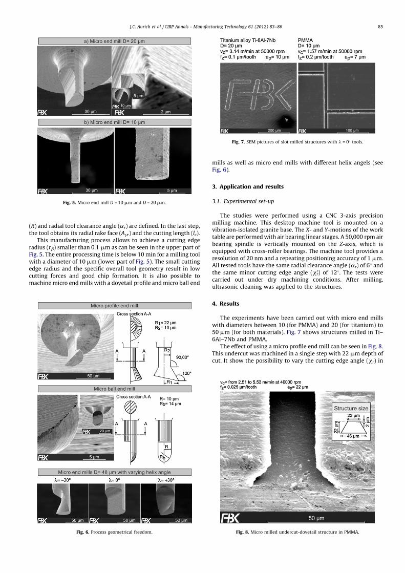
g. 8.h of) in
J.C. Aurich et al. / CIRP Annals - Manufacturing Technology 61 (2012) 83–86 85
(R) and radial tool clearance angle (ar) are defined. In the last step,the tool obtains its radial rake face (Agr) and the cutting length (lc).
This manufacturing process allows to achieve a cutting edgeradius (rb) smaller than 0.1 mm as can be seen in the upper part ofFig. 5. The entire processing time is below 10 min for a milling toolwith a diameter of 10 mm (lower part of Fig. 5). The small cuttingedge radius and the specific overall tool geometry result in lowcutting forces and good chip formation. It is also possible tomachine micro end mills with a dovetail profile and micro ball end
mills as well as micro end mills with different helix angels
Fig. 6).
3. Application and results
3.1. Experimental set-up
The studies were performed using a CNC 3-axis precismilling machine. This desktop machine tool is mounted ovibration-isolated granite base. The X- and Y-motions of the wtable are performed with air bearing linear stages. A 50,000 rpmbearing spindle is vertically mounted on the Z-axis, whichequipped with cross-roller bearings. The machine tool providresolution of 20 nm and a repeating positioning accuracy of 1 mAll tested tools have the same radial clearance angle (ar) of 68
the same minor cutting edge angle (xr0) of 128. The tests w
carried out under dry machining conditions. After millultrasonic cleaning was applied to the structures.
4. Results
The experiments have been carried out with micro end mwith diameters between 10 (for PMMA) and 20 (for titanium50 mm (for both materials). Fig. 7 shows structures milled in6Al–7Nb and PMMA.
The effect of using a micro profile end mill can be seen in FiThis undercut was machined in a single step with 22 mm deptcut. It show the possibility to vary the cutting edge angle (xr
Fig. 5. Micro end mill D = 10 mm and D = 20 mm.
Fig. 7. SEM pictures of slot milled structures with l = 08 tools.
Fig. 6. Process geometrical freedom. Fig. 8. Micro milled undercut-dovetail structure in PMMA.
orde908
TmacTo cside
Fburracrohelixnegaformdowrouga po
5. C
Ithe
J.C. Aurich et al. / CIRP Annals - Manufacturing Technology 61 (2012) 83–8686
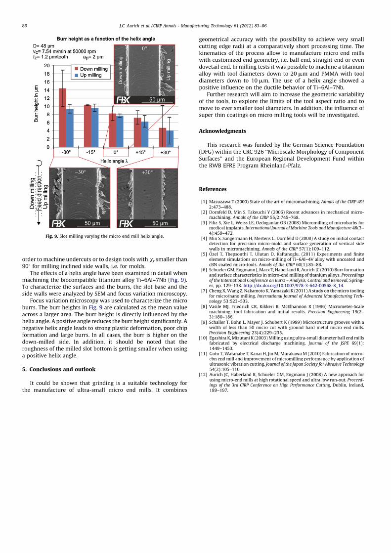
r to machine undercuts or to design tools with xr smaller thanfor milling inclined side walls, i.e. for molds.he effects of a helix angle have been examined in detail whenhining the biocompatible titanium alloy Ti–6Al–7Nb (Fig. 9).haracterize the surfaces and the burrs, the slot base and the
walls were analyzed by SEM and focus variation microscopy.ocus variation microscopy was used to characterize the micros. The burr heights in Fig. 9 are calculated as the mean valuess a larger area. The burr height is directly influenced by the
angle. A positive angle reduces the burr height significantly. Ative helix angle leads to strong plastic deformation, poor chipation and large burrs. In all cases, the burr is higher on then-milled side. In addition, it should be noted that thehness of the milled slot bottom is getting smaller when usingsitive helix angle.
onclusions and outlook
t could be shown that grinding is a suitable technology formanufacture of ultra-small micro end mills. It combines
geometrical accuracy with the possibility to achieve very smallcutting edge radii at a comparatively short processing time. Thekinematics of the process allow to manufacture micro end millswith customized end geometry, i.e. ball end, straight end or evendovetail end. In milling tests it was possible to machine a titaniumalloy with tool diameters down to 20 mm and PMMA with tooldiameters down to 10 mm. The use of a helix angle showed apositive influence on the ductile behavior of Ti–6Al–7Nb.
Further research will aim to increase the geometric variabilityof the tools, to explore the limits of the tool aspect ratio and tomove to ever smaller tool diameters. In addition, the influence ofsuper thin coatings on micro milling tools will be investigated.
Acknowledgments
This research was funded by the German Science Foundation(DFG) within the CRC 926 ‘‘Microscale Morphology of ComponentSurfaces’’ and the European Regional Development Fund withinthe RWB EFRE Program Rheinland-Pfalz.
References
[1] Masuzawa T (2000) State of the art of micromachining. Annals of the CIRP 49/2:473–488.
[2] Dornfeld D, Min S, Takeuchi Y (2006) Recent advances in mechanical micro-machining. Annals of the CIRP 55/2:745–768.
[3] Filiz S, Xie L, Weiss LE, Ozdoganlar OB (2008) Micromilling of microbarbs formedical implants. International Journal of Machine Tools and Manufacture 48(3–4):459–472.
[4] Min S, Sangermann H, Mertens C, Dornfeld D (2008) A study on initial contactdetection for precision micro-mold and surface generation of vertical sidewalls in micromachining. Annals of the CIRP 57(1):109–112.
[5] Ozel T, Thepsonthi T, Ulutan D, Kaftanoglu. (2011) Experiments and finiteelement simulations on micro-milling of Ti–6Al–4V alloy with uncoated andcBN coated micro-tools. Annals of the CIRP 60(1):85–88.
[6] Schueler GM, Engmann J, Marx T, Haberland R, Aurich JC (2010) Burr formationand surface characteristics in micro-end milling of titanium alloys. Proceedingsof the International Conference on Burrs – Analysis, Control and Removal, Spring-er, pp. 129–138. http://dx.doi.org/10.1007/978-3-642-00568-8_14.
[7] Cheng X, Wang Z, Nakamoto K, Yamazaki K (2011) A study on the micro toolingfor micro/nano milling. International Journal of Advanced Manufacturing Tech-nology 53:523–533.
[8] Vasile MJ, Friedrich CR, Kikkeri B, McElhannon R (1996) Micrometer-Scalemachining: tool fabrication and initial results. Precision Engineering 19(2–3):180–186.
[9] Schaller T, Bohn L, Mayer J, Schubert K (1999) Microstructure grooves with awidth of less than 50 micro cut with ground hard metal micro end mills.Precision Engineering 23(4):229–235.
[10] Egashira K, Mizutani K (2003) Milling using ultra-small diameter ball end millsfabricated by electrical discharge machining. Journal of the JSPE 69(1):1449–1453.
[11] Goto T, Watanabe T, Kanai H, Jin M, Murakawa M (2010) Fabrication of micro-cbn end mill and improvement of micromilling performance by application ofultrasonic vibration cutting. Journal of the Japan Society for Abrasive Technology54(2):105–110.
[12] Aurich JC, Haberland R, Schueler GM, Engmann J (2008) A new approach forusing micro-end mills at high rotational speed and ultra low run-out. Proceed-ings of the 3rd CIRP Conference on High Performance Cutting, Dublin, Ireland,189–197.
Fig. 9. Slot milling varying the micro end mill helix angle.