Embed Size (px)
Citation preview

Manufacturing Model using Pro/MANUFACTURING
INTRODUCTION Before creating the manufacturing model, the part for manufacturing should be ready for use. Basic procedure for creating manufacturing model is as following:
1. Create work piece that contains the part. 2. Setup operation and machining sequences. 3. Cutter location simulation and/or shaded material removal
simulation. 4. Create NC code using NC-POST.
After creating the NC code, the file will be saved as partname.tap.
CREATING MANUFACTURING MODEL
[A] Creating Work Piece
1. Launch Pro/E and click on [File] > [Set Working Directory] , change the working directory to the directory that you save your part. You can skip this step if you are already done it.
2. Click on [File] > [New] > Select [Manufacturing] type and [NC Assembly] as sub-type > Enter file name (e.g. Moon1) > Click [OK]
1

3. Under the Manufacturing Menu select: Mfg Model>
Assemble>Ref Model. The open file window will display on the screen. Select the part you want to machine. (e.g. moon1.prt) and click [Open].
2

Select “Coord Sys” on the dashboard to assemble your reference part to the assembly coordinate.
Click on the coordinate system of the part and then click on the coordinate system of the assembly as shown below:
The STATUS will show “Fully Constrained”. Click
4. After assembling your reference part, under [MFG MDL], select [Create] > [Workpiece] on the pull-down menu at the right hand side.
5. Enter a file name for your work piece (e.g. Moonwk1) on bottom
of the screen and hit ENTER.
6. Under the FEAT CLASS sub-menu, click on [Solid] > [Protrusion].
3

7. Under Create-SOLID OPTS, [Extrude]>[Solid] are highlighted.
Select [Done].
8. Select [Placement] > [Define]
9. Select or create a SKETCHING PLANE. Click on the top of the circle as sketching plane.
10. Keep default “Reference” selection and “Click” on the Sketch
button.
11. Click on four sides of the block as references. Close the References window.
4

12. Select the Rectangular button from the tool bar menu.
13. Click on the up-left corner of your piece and then move your mouse to the down-right corner and click left mouse button again to form a rectangular.
14. Click the CHECK mark when you are done.
15. Enter depth at the bottom of the screen. (enter 0.75 inch as
depth). Hit Return.
16. Use Preview button to see your work piece. Change direction as necessary to have your work piece cover the reference part.
5

17. Click on when done. Your workpiece is created. You can
rotate the assembly and see the green rectangle block.
18. Select [Done/Return] in MFG MDL menu.
[B] Define Workcells, Operations, Fixture
1. Click on [Mfg Setup] under MANUFACTURING menu. 2. Give an operation name (e.g. moon1).
6

3. Click on the button on the right of NC Machine, , and setup machine properties. Click OK when it’s done.
4. Select Reference>Machine Zero to setup coordinate system. 5. Now you need to create a coordinate system. Select Datum
Coordinate System on the right-side tool button.
7

6. Highlight and click on the lower-left corner of the workpiece.
7. Click on Orientation Tab. Highlight the first “Use” and select the horizontal edge as X. Select second “Use” and select the side edge as Y. Flip the direction as needed. Make sure your Z direction is pointed UP.
8. Click OK when it’s done.
9. Click on Retract>Surface selection button in the Operation Setup window. Then click the Along Z axis and type in 0.5 for the position of reaction plane. Click OK when it’s done.
8

10. Click OK in the Operation Setup window. Then Click
[Done/Return]
11. Select Machining under Manufacture menu. [Machining] >[NC Sequence]> [Volume] > [3 Axis]>[Done].
12. Under SEQ SETUP, make sure [Tool], [Parameters],
[Volume] are check marked and then click [Done].
13. Under Tool Setup window, set Name to T0001, Diameter to 0.5, Length to 1. Then click on [Apply], and click OK. This will set up the first tool for you.
9

14. Under MFG PARAMS menu, click on [Set]. Enter parameters
as the followings:
10
15. After entering all parameters, click on [File] > [Exit], and then click on [Done] in the MFG PARAMS menu.
16. Click [Mill Volume Tool] in tool-bar menu 17. Select Extrude Tool, 18. Click on [Placement] > [Define]
19. Select the top of the workpiece as sketching plane.
20. Make sure the direction arrow is pointed down then click
[Sketch]. 21. Select four sides of the workpiece as references then click
CLOSE in the References window.
22. In SKETCH mode, select Rectangle and click and drag a rectangle that is slightly larger than the workpiece. Dimensions are shown below: (5.5"x4.5"). Click on the Selection arrow and then double click the dimension to change it as following.
11

12

23. Click the CHECK mark when you are done.
24. Enter depth of 0.25 inch on top of the screen; change direction of extrusion as necessary, and then hit Enter.
25. Click on the Dashboard.
26. Under pull-down menu, select [Edit] and then select the [Trim] then click on the reference parts to trim. Then click .
27. Rotate your assembly to the angle that you can see the
simulation.
28. Select [Play Path] > [NC Check].
29. After calculations, click on [Run] to see the simulation.
13
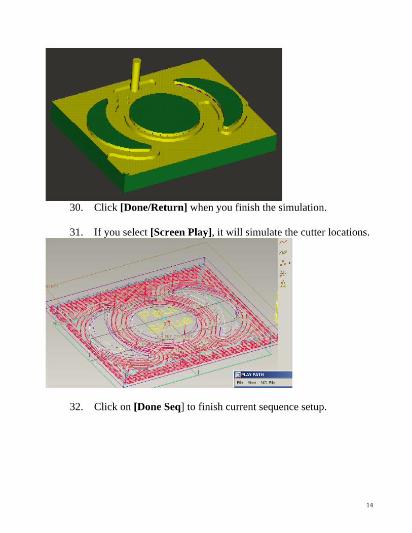
30. Click [Done/Return] when you finish the simulation.
31. If you select [Screen Play], it will simulate the cutter locations.
32. Click on [Done Seq] to finish current sequence setup.
14

SETTING UP THE 2nd SEQUENCE: (Holemaking)
1. Click [NC Sequence] > [New Sequence] > [Holemaking] > [3 Axis]>[Done].
2. Select [Drill] > [Standard] > [Done].
3. If you are not using the same tool, make sure [Tool] is selected,
and then select [Done] under SEQ SETUP menu. Then you can setup your tool.
4. Set up Tool, make sure the Tool Number is 2.
Click [Apply] and then [OK]
5. Select [Set] in MFG PARAMS menu and enter parameters as followings:
15

6. Click on [File] > [Exit] in parameter setting window. 7. Select [Done] in MFG PARAMS menu.
8. In Hole Selection window, select [Pattern] > [Add] under Axes
Tab.
9. Click on one of the axis of holes (e.g. A_5 & A_22) . Click [OK] under Select window
10. The axes selected will show in the window.
16

11. (Optional) Select [Depth] > [Blind].
12. (Optional) Click [Surface] > [Select] in the Start Surface
frame and select the top surface of the hole. (You can use Query Select.)
13. (Optional) Click [Z-Depth] and enter 0.25 in the End Surface
frame
14. Click [OK].
17

15. Click [OK] in the Hole Selection window.
16. Click [Done/Return] in HOLES menu.
17. Select [Play Path] > [NC Check].
18. Run simulation. Click [Done/Return] when finished.
19. Click [Done Seq].
18

CREATING THE 3RD SEQUENCE (Profiling):
1. Click on MANUFACTUR > Machining > [NC Sequence] > [New Sequence] > [Profile] > [Done].
2. Under SEQ Setup menu, select the [Tool] and leave others as
default, then click [Done].
3. Under Tool Setup window, set Name to T0003 Diameter to 0.125, Type as Ball Mill; Change Tool Number to 3 under Settings tab. Click on [Apply], and click on [OK]. This will set up the Third tool for you.
4. In MFG PARAMS menu, click [Set] and type in all parameters as
following:
19

5. Click on [File] > [Exit].
6. Click [Done] in MFG PARAMS menu.
7. Under SURF PICK menu, click [Model] > [Done].
8. Select the round corners of the moon shape and click [OK] when
finished.
20

9. Under SURF/LOOP menu: Surface > Done 10. Click [Show] to see if selections are correct.
11. Click [Done/Return].
12. Click [Play Path] > [NC Check] or [Screen Play].
13. Click [Done/Return] when finished.
14. Click [Done Seq] to finish this sequence.
15. Repeat Steps 1-15 but select the chamfer around the circle as
surfaces.
16. Repeat Steps 1-15 but select the round corner of another moon shape.
View the shaded simulation of whole operation:
1. Click [CL Data] > [NC Check] > [Run] > [Create] > [Operation] > [moon1].
2. Under Save As window, just click [OK]. You will see the shaded
simulation of the whole operation.
21

Generating NC Code:
1. Click [CL Data] > [Output] > [Operation] , then select your operation. (Moon1).
2. Click [File] under PATH menu.
3. Check the [CL file] and [MCD File] > [Done].
4. Type in a CL file name. (Default is OP010) (e.g. Moon1)
5. Click [OK] when done.
6. Click [Done] in PP OPTIONS menu.
7. Select [Fadal01] (or UNCX01.P14) from PP List
8. After process, a Moon1.tap file will be created under the working
directory.
22
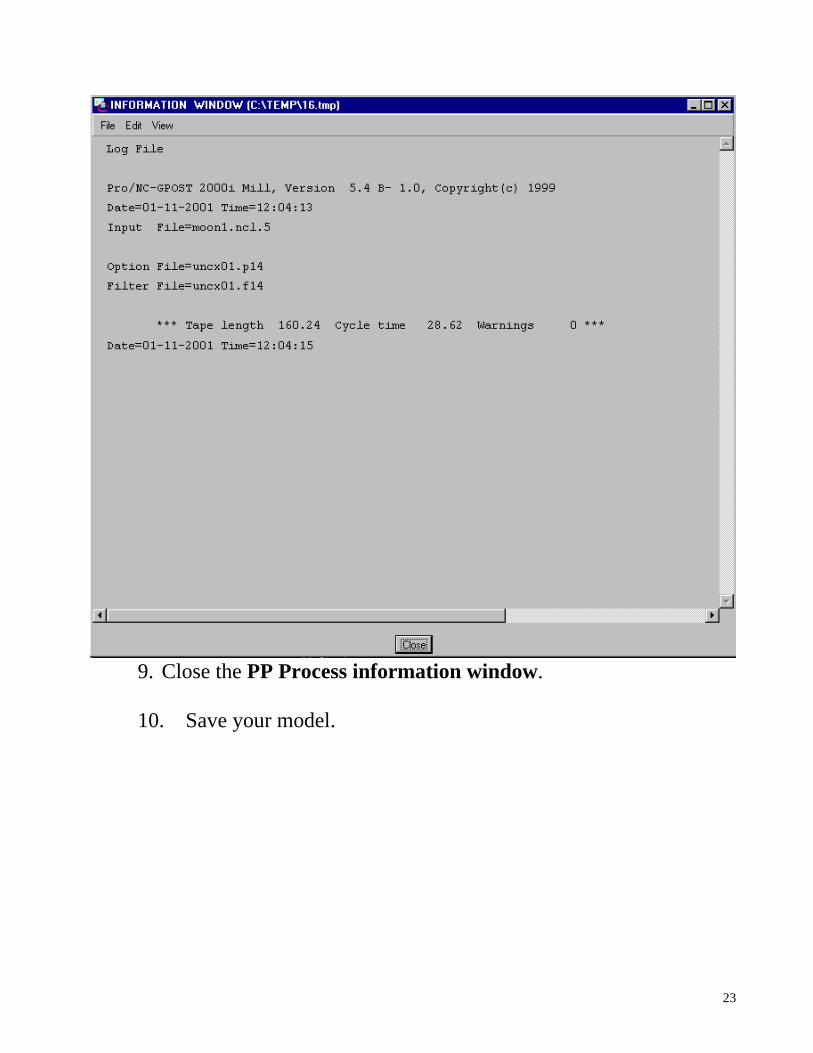
9. Close the PP Process information window.
10. Save your model.
23