Embed Size (px)
Citation preview

i
ii
MANUFACTURING PROCESS
ARTICLE
2019
By: Rino Andias Anugraha and Assistant Team
School of Industrial Engineering
TelkomUniversity

iii
INTRODUCTION
Praise be to Allah Subhanahu wa Ta'ala, because with His grace and mercy, the writer and the
team were given the opportunity to complete the Article Module for the implementation of
the manufacturing process practicum in the 2019/2020 educational year.
In this module the authors and team re-designed our masterpiece of practicum products
namely Stirling Engine, where we added 2 pistons and enlarged the scale of parts that were
made in the previous version for the needs of integrated practicum activities in the Faculty of
Industrial and System Engineering
Prosman Laboratory Adviser
Rino Andias Anugraha, ST., MM
NIP : 99750032

iv
MANUFACTURING PROCESS LABORATORY ASSITANTS 2019/2020
Aldyan Nurfaizi B. Tau
Alia Agistina
Anak Agung Sri Nandini
Anggit Pratama
Bagas Arganto P.
Bela Pitria Hakim
Damario Haznam
Farras Burhanuddin
Gitanjali Widayu Diatri
Mario Adiprana Muki
Nafisha Herma Hanifha
Pangestu Rizky Purnama
Satria Rahmadani Putra
Sri Yuzarnimar
Tri Maisyah Nugrah Samudro
Zakaria Gunada
Abdurrahman Rashif
Annastasya Septiani
Aquilla Yunma Imaristha
Arief Tri Hendrayanto
Corie Ariesta Arbay
Dhiya Shafa Azizah
Dimas Rayhandika
Elisa Intan Puspitasari
Gamaliel Situmeang
Indah Ekanurhayati
Irfanul Zuhdi Nufrinal
Kholiq Giffari
M. Fachri Husamuddin
M. Arash Arisiah
M. Raihan Arrafi
M. Sohibul Wafa
Nisri Husna Faadhilah
Rafi Pragiwaka Gani
Tirza Ayu Nursazabillah

5
MANUFACTURING PROCESS
LABORATORY
Document
Number
MODULE 2.2 Form
Number
Valid 2019
Module Machining Process
Labwork NC Code Turning
Student Outcomes SO2. Able to apply mathematics, science and engineering
principles to solve complex engineering problems in
integrated systems (including human, material, equipment,
energy, and information)
Learning Outcomes LO14. Students are able to make a process plan for a given
product

6
A. Tools and Requirements
Tools & Software Requirements
1. HAAS Control Simulator 1. Labwork of Module 2.2
2. Guideline of Module 2.2
3. Stationary
B. References
Autodesk CAM . (2014). Fundamentals of CNC Machining. Autodesk CAM. (2014). Fundamentals of Machining. CNC Programming Basics, Tutorials, and Example Code. (2019, March 2019 19th). Retrieved from http://www.helmancnc.com/fanuc-g71-turning-cycle/ HAAS Automation Inc. (2015). Lathe Series Training Manual: HAAS CNC Lathe Programming. USA: Productivity inc. Manufacturing Process Laboratory. (2018). Manufacturing Process Training Module. Telkom University. Manufacturing Process Laboratory. (2018). Modul Pelatihan NC Code Milling dan Turning Novice 1.0. Bandung: Universitas Telkom. Manufacturing Process Laboratory. (2018). Modul Pelatihan Proses Manufaktur . Bandung: Universitas Telkom. Manufacturing Process Laboratory. (2018). NC Code Milling and Turning Training Module. Bandung: Telkom University.

7
C. Labwork Steps
Flow Process Charts Process Description
1. Read the study case well. Because the study
case contained information that will be done
in the labwork.
2. Pay attention to detail case and instruction
specifications for each process.
3. Create NC Code and input it on to HAAS
Control Simulator.
4. Simulate NC Code that has been created on
HAAS Control Simulator according to the
tutorial on the labwork.
START
Read the study
case
Pay attention to
the
specifications
of each process
Create NC
Code
Simulate NC
Code
END

8
MODULE 2.2
MACHINING PROCESS: NC CODE LATHE
1.1 Students are able to understand about Lathe/Turning Machining Processes.
1.2 Students are able to understand about NC Code Lathe.
1.3 Students are able to create and simulate NC Code of Lathe Processes.
1.4 Students are able to operate HAAS Control Simulator.
2.1 Overview CNC Turning.
2.2 Lathe Components.
2.3 Lathe Coordinate System.
2.4 2-Axis Lathe CNC Machine.
2.5 Tool Nose Compensation.
2.6 Part Datum.
2.7 Tools and Tool Holders.
2.8 Program Structure of NC Code Lathe.
2.9 Setup.
2.10 G71 O.D./I.D. Stock Removal.
2.11 G70 0.D./I.D. Finishing Cycle.
2.12 G75 O.D./I.D. Grooving Cycle.
2.13 G75 Cut Off.
2.14 G81 Drill Canned Cycle.
2.15 G83 Normal Peck Drilling Canned.
1. OBJECTIVES
2. OUTLINES

9
3.1 Overview CNC Turning
CNC Turning is a manufacturing process in which bars of material are held in a
chuck and rotated while a tool is fed to the piece to remove material to create the
desired shape. A turret (shown center), with tooling attached is programmed to
move to the bar of raw material and remove material to create the programmed
result.
Figure 2.2.1 Turning Machine (Autodesk CAM, 2014)
There are many different configurations of CNC lathes. Some have two
spindles, some two tool turrets, and some even integrate milling or grinding in the
same machine. There is also variation between similar machines.
3.2 Lathe Components
Major components of a CNC Lathe.
Figure 2.2.2 Lathe Components (Autodesk CAM , 2014)
3. BASIC THEORY
1. Sheetmetal
2. Door
3. Spindle
4. Turret
5. Control

10
1. Sheetmetal
Protective housing that contain cutting chips and capture coolant for recycling.
2. Door
Door is closed during operation. Lathes can be dangerous if the part is thrown
or a tool breaks during machining. The window is made from a special high impact
glass. The lathe should not be operated if this glass is cracked.
3. Spindle
Spindle is attached at one end the machine drive system. The other end
attaches the chuck, which grips the part.
Figure 2.2.3 Spindle Detail (Autodesk CAM , 2014)
4. Turret
Turret holds and moves the tools. Tools are bolted to the turret using a variety
of specialized holders, depending on the type of the tool. The turret indexes to
present the tool to the workpiece.
Figure 2.2.4 Turret Details (Autodesk CAM , 2014)
1. Spindle
2. Chuck
3. Jaws
4. Part
1. Tool Station
2. Tool Block
3. Face/Turn Tool
4. Face Groove Tool
5. Turret
6. Boring Bar Tool
7. Live Tool (Radial Mount)
8. Live Tool (Axial Mount)

11
5. Control
CNC control used to operate the machine, includes functions to make
programming easier.
3.3 Lathe Coordinate System
Most lathes are 2D machines based on a Z-X Coordinate System. As shown in
figure 2.2.5, the Z-axis is parallel to the machine spindle and the X-axis is
perpendicular to the spindle. Normal spindle rotation is counterclockwise, though
direction can be reversed for left-handed threads just like with a mill by commanding
the proper G-code.
Figure 2.2.5 Lathe Coordinate System (Autodesk CAM , 2014)

12
3.4 Axis Lathe CNC Machine
The definition of lathe is a machine that shapes objects by rotating them while a
shaping tool such as a chisel is applied to its surface or in other reference it called
turning process. A lathe is a machine tool which turn cylindrical material, touches a
cutting tool to it and cuts the material. The lathe is one of the machine tools most
well used by machining. A lathe machine can be used to create symmetrical shapes
into a piece of wood metal or other material.
Figure 2.2.6 Lathe Operations (Autodesk CAM , 2014)

13
3.5 Tool Nose Compensation
The corners of lathe tools are radii. The imaginary tool tip is where vertical and
horizontal lines tangent to the cutting edge of the tool intersect. This point is found
by touching off the tool in the Z and X directions on the part or using a tool probe.
Because the imaginary tool tip can be found with great precision, it is used to control
the tool. That is, all the Z-X coordinates in the G-code program are in reference to
this point. Tool positions are easy to calculate parallel to the machine axes, but more
complex for arcs and chamfers.
Figure 2.2.7 Tool Nose Compensation (Autodesk CAM , 2014)

14
3.6 Part Datum
The part datum is usually set as the center-face of the finished part.
Figure 2.2.8 Part Datum (Autodesk CAM , 2014)
Lathe tools have two tool offsets: Z and X, which is the distance from the
imaginary tool tip at home position to the part datum. There are two ways to set
lathe tool offsets. The first involves making a small cut (try cut) on the OD and face
of the stock material. The diameter is measured and entered in the control for the
X-axis offset. Subsequent tool offsets are found in reference to these faces.
Figure 2.2.9 Tool Offsets (Autodesk CAM , 2014)

15
3.7 Tools and Tool Holders
While lathes use some of the same tools that mills use, including spot drills, drills,
and taps, most turning is done using carbide inserts. Inserts are gripped in holders,
which in turn are bolted to the lathe turret.
Figure 2.2.10 Typical Lathe Tool Holders (Autodesk CAM , 2014)
3.8 Program Structure of NC Code Lathe
The table below is the structure of NC Code Lathe:
Table 2.2 1 Program Structure of NC Code Lathe
No. Structure Explanation
1. Program Number Contains the number of the program that will be or have been made. Consists of 5 digits. Examples of writing is ‘O00111’.
2. Homing Tool Tool is located in machine home, where initial tool is located.
3. Tool Selection Choosing the appropriate tool with the machining process.
4. Setting Spindle Turning on the spindle, set the spindle speed and the spindle direction.
5. Rapid Move To Starting Point
Tool moves quickly to the point of initial coordinates that have been determined prior to machining or before feeding workpiece.
6. Machining Program (G70/G71/G81/G83)
Contains machining program that will be or have been made according to the shape of the workpiece to be made.
7. Content of Program Contains a machining program according with the shape of the workpiece shape or part. Consisting of [P] the starting block and [Q] ending block.
8. Homing Tool Tool back toward machine home, applying a rapid move.
9. Spindle Off Turning off the spindle.
10. Ending Process Ending of running program.

16
3.9 Setup
The part is gripped in hard jaws, soft jaws, or collet. Part datum is usually the
center-face of the finished part. Provide enough excess stock to securely grip the
part. The back side of the part should be as close to the jaws as possible while
providing clearance for the cut off tool.
Figure 2.2.11 Setup
3.10 G71 O.D./I.D. Stock Removal
G71 Removal Stock is a program used for rough-material removal from
a CNC Lathe component. Cutting can be done in simple straight line or a
complex contour can also machine easily.
Machining Program:
D = Depth of cut for each pass of stock removal, positive radius.
F = Feed rate to use throughout G71 PQ block (the unit is in
mm/revolution).
I = X-Axis size and direction of G71 rough pass allowance, radius.
K = Z-Axis size and direction of G71 rough pass allowance.
P = Starting block number of path to rough.
Q = Ending block number of path to rough.
S = Spindle speed to use throughout G71 PQ block.
T = Tool and offset to use throughout G71 PQ block.
(G71 P……Q…...U…...W…...D…...F)
1. Jaw
2. Chuck
3. Stock
4. Extra Stock for
Grip/Cut Off
5. Part Datum
6. Extra Stock for
Facing

17
U = X-Axis size and direction of G71 finish allowance, diameter.
W = Z-Axis size and direction of G71 finish allowance.
Programming Example G71 (O.D. Turning)
In this case, G71 using tool number 1, with spindle speed is 1000 rpm.
The finishing allowance of X-axis and Z-axis in G71 is 0.1 mm and 0.1 mm, and
the depth of cut is 0.2 mm and while the feed rate is 0.15 mm/rev with starting
point at X = 41 and Z = 2.
Figure 2.2.12 G71 O.D. Example
Therefore, these are the NC Code that fulfill that case:
O01111 (O.D. Turning); Program Number
G28 U0; Homing Tool
G28 W0; Homing Tool
T101; Selection Tool No. 1 (T101)
G97 S1000 M03; Setting Spindle
G00 G54 Z2.; Rapid Move to Start Point
X41.;
G71 P1 Q2 U0.1 W0.1 D0.2 F0.15; Machining Program
N1 G00 X10.; Program Content
G01 Z-5.;
G03 X20. Z-10. R5.;
G01 Z-15.;
Z-20. X30.;
Z-25.;
G02 X40. Z-30. R5.;
G01 Z-32.;
N2 X41.;

18
Notes:
[1] Black font is used as the standard form of code structure.
[2] Blue font is used as the movement of tool that follows the shape of the
geometry.
[3] Red font is used as the tool movement in G Code.
Programming Example G71 (I.D. Turning)
In this case, G71 using tool number 1, with spindle speed is 1000 rpm.
The finishing allowance of X-axis and Z-axis in G71 is 0.1 mm and 0.1 mm,
and the depth of cut is 0.2 mm and while the feed rate is 0.15 mm/rev with
starting point at X=0 and Z=2.
Figure 2.2.13 G71 I.D. Example
Therefore, these are the NC Code that fulfill that case:
O02222 (I.D. Turning); Program Number
G28 U0; Homing Tool
G28 W0; Homing Tool
T101; Selection Tool No. 1 (T101)
G97 S1000 M03; Setting Spindle
G00 G54 X0. Z2.; Rapid Move to Start Point
X0.;
G71 P1 Q2 U0.1 W0.1 D0.2 F0.15; Machining Program
G28 U0; Homing Tool
G28 W0; Homing Tool
M05; Spindle Off
M30; End of Program
19
N1 G00 X45.; Program Content
G01 Z-5.;
X35. Z-10.;
Z-15.;
X23.;
G03 X13. Z-20. R5.;
G01 Z-23.;
N2 X0.;
G28 U0; Homing Tool
G28 W0; Homing Tool
M05; Spindle Off
M30; End of Program
Notes:
[1] Black font is used as the standard form of code structure.
[2] Blue font is used as the movement of tool that follows the shape of the
geometry.
[3] Red font is used as the tool movement in G Code.

20
3.11 G70 O.D./I.D. Finishing Cycle
G70 finishing cycle is a phase consist of a pass along the programmed
tool path to remove excess material left by roughing phase, it makes the
workpiece smoother. G70 is used after the removal cycles such as G71, G72,
and G73. But it can also be used alone.
Machining Program:
P = Starting block number of routine to execute.
Q = Ending block number of routine to execute.
F = Feed rate (mm/rev).
Figure 2.2.14 G70 Finishing Cycle
(G70 P…...Q…...F…...)

21
Programming Example (G70)
In this case, G70 using tool number 1, with 1200 rpm spindle speed,
while the feed rate is 0.15 mm/rev.
Figure 2.2.15 G70 Example
Therefore, these are the NC Code that fulfill that case:
O03333 (Finishing Cycle); Program Number
G28 U0; Homing Tool
G28 W0; Homing Tool
T101; Selection Tool No. 1 (T101)
G97 S1200 M03; Setting Spindle
G00 G54 Z2.; Rapid Move to Start Point
X41.;
G71 P1 Q2 U0.1 W0.1 D0.2 F0.15; Machining Program
N1 G00 X10.; Program Content
G01 Z-5.;
G03 X20. Z-10. R5.;
G01 Z-15.;
Z-20. X30.;
Z-25.;
G02 X40. Z-30. R5.;
G01 Z-32.;
N2 X41.; Program Number
S1200;
G70 P1 Q2 F0.1;
G28 U0; Homing Tool

22
G28 W0; Homing Tool
M05; Spindle Off
M30; End of Program
Notes:
[1] Black font is used as the standard form of code structure.
[2] Blue font is used as the movement of tool that follows the shape of the
geometry.
[3] Red font is used as the tool movement in G Code.
3.12 G75 O.D./I.D. Grooving Cycle
G75 Grooving cycle is used for external or internal grooving.
Machining Program:
X = Axis absolute grooving depth, diameter value (mm).
Z = Axis absolute location to the furthest peck (mm).
I = X-Axis size of increment between pecks in a cycle (radius measure).
K = Z-Axis size of increment between peck cycles.
F = Feed rate (mm/rev).
Figure 2.2.16 G75 Grooving Cycle (Autodesk CAM , 2014)
(G75 X…...Z…...I…...K…...F…...)

23
Programming Example (G75 O.D.)
In this case, G75 O.D. using tool number 2 (tool diameter 2 mm), with
spindle speed is 800 rpm. The X-axis pecking depth is 0.2 mm and Z-axis
pecking depth is 1.5 mm and while the feed rate is 0.15 mm/rev with starting
point at X = 18 and Z = -20.
Figure 2.2.17 G75 O.D. Example
Therefore, these are the NC Code that fulfill that case:
O04444 (OD Grooving); Program Number
G28 U0; Homing Tool
G28 W0; Homing Tool
T202; Selection Tool No. 2 (T202)
G97 S800 M03; Setting Spindle
G00 G54 Z-20.; Rapid Move to Start Point
X18.;
G75 X10. Z-12. I0.2 K1.5 F0.15; Program Content
G28 U0; Homing Tool
G28 W0; Homing Tool
M05; Spindle Off
M30; End of Program

24
Notes:
[1] Black font is used as the standard form of code structure.
[2] Blue font is used as the movement of tool that follows the shape of the
geometry.
[3] Red font is used as the tool movement in G Code.
Programming Example (G75 I.D.)
In this case, G75 I.D. using tool number 3 (tool diameter 2 mm), with
spindle speed is 800 rpm. The X-axis pecking depth is 0.2 mm and the Z-axis
pecking depth is 1.5 mm and while the feed rate is 0.15 mm/rev with starting
point at X=0 and Z= 5.
Figure 2.2.18 G75 I.D. Example
Therefore, these are the NC Code that fulfill that case:
O05555 (ID Grooving); Program Number
G28 U0; Homing Tool
G28 W0; Homing Tool
T303; Selection Tool No. 3 (T303)
G97 S800 M03; Setting Spindle
G00 G54 Z5.; Rapid Move to Start Point
X0.;
G01 Z-20. F1.;
G75 X30. Z-12. I0.2 K1.5 F0.15; Program Content
G28 U0; Homing Tool
G28 W0; Homing Tool
25
M05; Spindle Off
M30; End of Program Notes:
[1] Black font is used as the standard form of code structure.
[2] Blue font is used as the movement of tool that follows the shape of the
geometry.
[3] Red font is used as the tool movement in G Code.
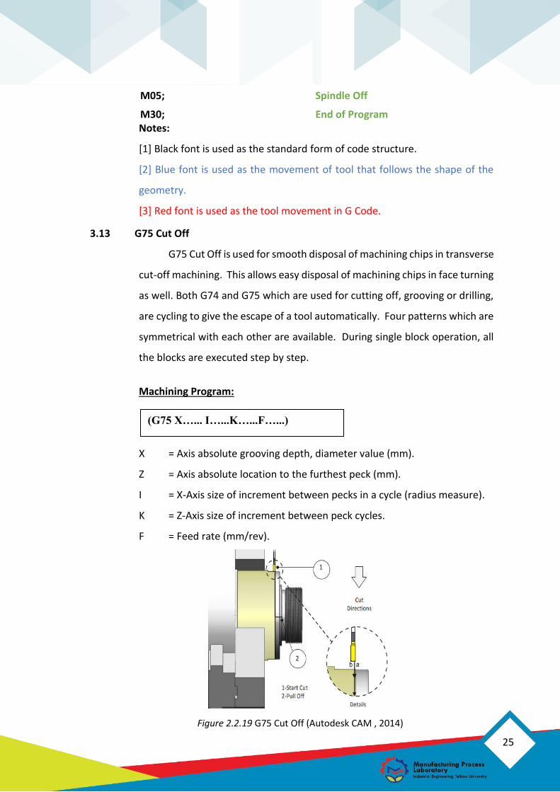
3.13 G75 Cut Off
G75 Cut Off is used for smooth disposal of machining chips in transverse
cut-off machining. This allows easy disposal of machining chips in face turning
as well. Both G74 and G75 which are used for cutting off, grooving or drilling,
are cycling to give the escape of a tool automatically. Four patterns which are
symmetrical with each other are available. During single block operation, all
the blocks are executed step by step.
Machining Program:
X = Axis absolute grooving depth, diameter value (mm).
Z = Axis absolute location to the furthest peck (mm).
I = X-Axis size of increment between pecks in a cycle (radius measure).
K = Z-Axis size of increment between peck cycles.
F = Feed rate (mm/rev).
Figure 2.2.19 G75 Cut Off (Autodesk CAM , 2014)
(G75 X…... I…...K…...F…...)

26
Programming Example (G75 Cut Off)
In this case, G75 Cut Off using tool number 2 (tool diameter 2 mm), with
spindle speed is 500 rpm. The X-axis pecking depth is 0.2 mm and while the
feed rate is 0.08 mm/rev with starting point at X = 42 and Z= 2.
Figure 2.2.20 G75 Cut Off Example
Therefore. These are the NC Code that fulfill that case:
O06666 (OD Grooving); Program Number
G28 U0; Homing Tool
G28 W0;
T202; Selection Tool No. 2 (T202)
G97 S500 M03; Setting Spindle
G00 G54 Z2.; Rapid Move to Start Point
X42.;
G01 Z-22. F1.;
G75 X0. I0.2 F0.08; Program Content
G28 U0; Homing Tool
G28 W0; Homing Tool
M05; Spindle Off
M30; End of Program
Notes:
[1] Black font is used as the standard form of code structure.
[2] Blue font is used as the movement of tool that follows the shape of the
geometry.

27
[3] Red font is used as the tool movement in G Code.
3.14 G81 Drill Canned Cycle
G81 Drill Canned Cycle is the machining process to make prefix hole as
a mark so that the further process still on its axis.
Machining Program:
Z = Absolute Z-Depth (feeding to Z-Depth from R-Plane) (mm)
R = Rapid to R-Plane (where you rapid, to start feeding) (mm)
F = Feed rate (mm/rev)
Figure 2.2.21 G81 Drill Canned Cycle
3.15 G83 Normal Peck Drilling Canned
G83 Normal Peck Drilling Canned Cycle is a program to make a hole by
drilling with pecking.
Machining Program:
Z = Absolute Z-Depth (feeding to Z-Depth from R-Plane) (mm).
Q = Pecking Depth Amount, always incremental (if I, J, K are not used) (mm).
R = Rapid to R-Plane (where you rapid, to start feeding) (mm).
F = Feed rate (mm/rev).
(G81 Z…...R…...F…...)
(G83 Z…...Q…...R…...F…...)

28
Programming Example (G81 & G83)
In this case, G81 using tool number 4, with spindle speed is 500 rpm.
The hole depth is 3 mm and rapid to R-Plane is 5 mm while the feed rate is 0.05
mm/rev with starting point at X = 0 and Z = 10.
G83 using tool number 5, with spindle speed is 500 rpm. The hole depth
is 15 mm and the amount of pecking depth is 2 mm and rapid to R-Plane is 5
mm while the feed rate is 0.05 mm/rev with starting point at X = 0 and Z = 10.
Figure 2.2.22 G81 and G83 Example

29
Therefore, these are the NC Code that fulfill that case:
O07777 (Drilling) ; Program Number
G28 U0; Homing Tool
G28 W0;
T404; Selection Tool No. 4 (T404)
G97 S500 M03; Setting Spindle
G00 G54 Z10.; Rapid Move to Start Point
X0.;
G81 Z-3. R5. F0.05; Machining Program
G80 G01 Z10. F1.;
G28 U0; Homing Tool
G28 W0;
M05; Spindle Off
T505; Selection Tool No. 5 (T505)
G97 S500 M03; Setting Spindle
G00 G54 Z10.; Rapid Move to Start Point
X0.;
G83 Z-15. Q2. R5. F0.05; Machining Program
G80 G01 Z10. F1.;
G28 U0; Homing Tool
G28 W0; Homing Tool
M05; Spindle Off
M30; End of Program
Notes:
[1] Black font is used as the standard form of code structure.
[2] Blue font is used as the movement of tool that follows the shape of the
geometry.
[3] Red font is used as the tool movement in G Code.

30

31
Autodesk CAM . (2014). Fundamentals of CNC Machining.
CNC Programming Basics, Tutorials, and Example Code. (2019, March 2019 19th).
Retrieved from http://www.helmancnc.com/fanuc-g71-turning-cycle/
HAAS Automation Inc. (2015). Lathe Series Training Manual: HAAS CNC Lathe
Programming. USA: Productivity inc.
Manufacturing Process Laboratory. (2018). Manufacturing Process Training Module.
Telkom University.
Manufacturing Process Laboratory. (2018). NC Code Milling and Turning Training Module.
Bandung: Telkom University.
4. REFERENCES