Embed Size (px)
Citation preview

Mohammad Amir, Lecturer, Department of Mechanical Engineering., BHCET 1
Notes also available on the blog for downloading: aamirbhcet.spaces.live.com
Manufacturing Technology, ME-202-E Unit- 2 (Cores and Patterns) 05 February 2010
Syllabus:
• Cores: Types of cores, core prints, chaplets, and chills.
• Gating Systems: Gates and gating systems risers.
• Melting Furnaces: Cupola, charge calculations.
• Casting Defects & Cleaning: Fettling, defects in castings and their remedies, methods of testing of castings for
their soundness.
Cores:
These are the materials used for making cavities and hollow projections which cannot normally be produced by the
pattern alone. Any complicated contour or cavity can be made by means of cores so that really intricate shapes can be
easily obtained. These are generally made of sand and are even used in permanent moulds. In general, cores are
surrounded on all sides by the molten metal and are therefore subjected to much more severe thermal and mechanical
conditions and as a result, the core sand should be of higher strength than the moulding sand.
The normal characteristics desired of a core are:
1) Green strength: A core made of green sand should be strong enough to retain the shape till it goes for baking.
2) Dry strength: It should have adequate dry strength so that when the core is placed in the mould, it should be able to
resist the metal pressure acting on it.
3) Refractoriness: Since in most cases, the core is surrounded all around it is desirable that the core material should
have higher refractoriness.
4) Permeability: Some of the gases evolving from the molten metal and generated from the mould may have to go
through the core to escape out of the mould. Hence cores are required to have higher permeability.
5) Collapsibility: As the casting cools, it shrinks, and unless the core has good collapsibility (ability to decrease in size) it
is likely to provide resistance against shrinkage and thus can cause hot tears.
6) Friability: After the casting is completely cooled, the core should be removed from the casting before it is processed
further. Hence the friability (the ability to crumble) should also be a very important consideration.
7) Smoothness: The surface of the core should be smooth so as to provide a good finish to the casting.
8) Low gas emission: Because of the high temperatures to which a core is subjected to, it should allow only a minimal
amount of gases to be evolved such that voids in the castings can be eliminated.
Core Sands: The core sand should contain the sand grains, binders
and other additives to provide specific properties:
1) Sand: The silica sand which is completely devoid of
clay is generally used for making core sands. Coarse
silica, because o f its higher refractoriness is used in
steel foundries whereas the finer sands are used for
cast irons and non-ferrous alloys.
2) Binders: As explained earlier, core sands need to be
stronger than the moulding sand and therefore the
clay binder used in moulding sands is not enough
but somewhat better binders need to be used. The
normal binders are organic in nature, because these
would be burnt away by the heat of the molten
metal and thus make the core collapsible during the
cooling of the casting. The amount of binder
required depends to a great extent on the fineness
of the sand grains. Also, the amount of clay left in
the sand increases the consumption of the binder.
The binders generally used are, linseed oil, core oil,
resins, dextrin, molasses, etc. Core oils are mixtures
of linseed, soy, fish and petroleum oils and coal tar.
The general composition of a core sand mixture
could be core oil (1%) and water (2.5 to 6%). The
actual composition to be used depends on the size
and shape of the care and the alloy being cast.

Mohammad Amir, Lecturer, Department of Mechanical Engineering., BHCET 2
Notes also available on the blog for downloading: aamirbhcet.spaces.live.com
Manufacturing Technology, ME-202-E Unit- 2 (Cores and Patterns) 05 February 2010
Types of Cores: Various types of cores of different designs and sizes are
employed in different ways, in foundry work. A general
way of classify them is to do so according to their
shapes and positions in the prepared moulds. The main
types of these are described below:
1) Horizontal Core. It is the most common and simple
type of core. It is assembled in the mould with its
axis horizontal. Depending upon the shape of the
cross-section of the hole to be made in the casting,
It may have any shape of its cross-section but the
most commonly used, shape is cylindrical. This core
is supported in the mould at its both ends. Unless it
has a non-uniform cross-section, it is held in the
mould on the parting line such that its one half
remains in the cope and the remaining half in the
drag.
2) Vertical core. It is quite similar to a horizontal core
except that it is fitted in the mould with its axis
vertical, as shown in Fig. It rests on the seat made at
the bottom of the mould by the core print and is
further supported by being located in a similar seat
made in the cope. The top end of the core is
provided with more taper in order to have a smooth
fitting of the cope on the core. A major portion of
the core usually remains in the drag part of the
mould.
3) Balanced core. It is used to produce a blind hole
along a horizontal axis in a casting. As a matter of
fact it is nothing but a horizontal core with the
exception that it is supported only on one end. The
other end remaining free in the mould cavity. It is,
thus a sort of Cantilever- Since it has to support the
weight of the overhanging portion. The core print
provided on the pattern should be long enough so
that sufficient length of the core may be embedded
in the sand to balance the weight of the overhung.
However, if the overhung is too much, such
balancing will not be enough and the overhanging
length of the core will have to be supported by
means of Chaplets.
4) Hanging or Cover Core. A core which hangs
vertically in the mould and has no support at its
bottom is known as a hanging core. In such a case it
is obvious that the entire mould cavity will be
contained in the drag only. A good many green sand
cores formed in the cope by the pattern are of
hanging type. Even otherwise, dry sand cores can
also be suspended from copes by being suitably
fastened to them by means of wires or rods etc.,
extending from within the core body to the top of
the cope. Unlike this, a hanging core may be
supported on a seat made on the parting surface in
the drag, as shown in Fig below It is then known as
a Cover Core.
5) Wire core. It is also known as a Stop-off-Core. It is
employed when the hole is desired to be produced
in the casting at such a position that its axis falls
either above or below the parting line. In such a
core, its one side remains flush with the inner
surface of the mould and the core, thus, acts as a
stop-off. The back surface of this core is provided.
With enough taper for its easy location. Many other

Mohammad Amir, Lecturer, Department of Mechanical Engineering., BHCET 3
Notes also available on the blog for downloading: aamirbhcet.spaces.live.com
Manufacturing Technology, ME-202-E Unit- 2 (Cores and Patterns) 05 February 2010
names like Tail Core and Saddle Core etc. are also given to this type of core according to its shape and use.
Apart from the above there are a few other types also,
but they are not so commonly used. One such rarely
used type is a Ram-up Core, which is embedded in the
mould. Such a need arises when placement of core is
not possible after ramming. Similarly, when such a
pattern is to be used which carries no core prints, the
core is held between cope and drag simply due to the
pressure put by the former. It is known as a Kiss core.
Core Prints: The core prints are provided so that the cores are securely and correctly positioned in the mould cavity. The design of
core prints is such as to take care of the weight of the core before pouring and the upward metallostatic pressure of the
molten metal after pouring. The core prints should also ensure that the core is not shifted during the entry of the metal
into the mould cavity. The main force acting on the core when metal is poured into the mould cavity is due to buoyancy.
The buoyant force can be calculated as the difference in the weight of the liquid metal to that of the core material of the
same volume as that of the exposed core. It can be written as
P=V(ρ - d)
where
P = buoyant force, (N)
V = volume of the core in the mould cavity, cm3
ρ = weight density of the liquid metal, N/cm3
d = weight density of the core material = 1.65 x 10⁻²
N/cm3
Chaptets: Chaplets are metallic supports often kept inside the mould cavity to support the cores. These are of the, same
composition as that of the pouring metal so that the molten metal would provide enough heat to completely melt them
and thus fuse with it during solidification. Some of the types of chaplets normally used are shown in Fig. below.
Though the chaplet is supposed to fuse with the parent metal, in practice it is difficult to achieve and normally it forms a
weak joint in the casting. The other likely problem encountered in chaplets is the condensation of moisture which finally
ends up as blow holes. Generally the chaplets before they are placed in the mould, should be thoroughly cleaned of any
dirt, oil or grease. Because of the problem associated with chaplets, it is desirable to redesign the castings, as far as
possible. In order to calculate the required chaplet area, we need to know that what the unsupported load is.

Mohammad Amir, Lecturer, Department of Mechanical Engineering., BHCET 4
Notes also available on the blog for downloading: aamirbhcet.spaces.live.com
Manufacturing Technology, ME-202-E Unit- 2 (Cores and Patterns) 05 February 2010
Chills: In a casting, metallic chills are used in order to provide
progressive solidification or to avoid the shrinkage
cavities. Chills are essentially large heat sinks.
Whenever, it is not possible to provide a riser for a part
of the casting which is heavy, a chill is placed close to it
as shown in Fig., so that more heat is quickly absorbed
by the chill from the larger mass making the cooling
rate equal to that of the thin sections. Thus, this does
not permit the formation of a shrinkage cavity. But use
of a chill means essentially providing higher cooling rate
which is also likely to form a hard spot at the contact
area with the chill and may therefore cause a problem if
that area needs further processing by way of machining.
Elements of a Gating system: A gating systems refer to all those elements which are connected with the flow of molten metal from the ladle to the
mould cavity. The various elements that are connected with a gating system are shown in fig. the mainelements of a
gating system are as follows:
• Pouring basin
• Sprue
• Sprue base well
• Runner
• Runner extension
• Ingate
• Riser
Any gating system designed should aim at providing a defect free casting. This can be achieved by making provision for
certain requirements while designing the gating system. These are as follows:
1. The mould should be completely filled in the smallest time possible without having to raise metal temperature nor
use higher metal heads.
2. The metal should flow-smoothly into the mould without any turbulence. A turbulent metal flow tends to form dross
in the mould.
3. Unwanted material such as slag, dross and other mould material should not be allowed to enter the mould cavity.
4. The metal entry into the mould cavity should be properly controlled in such a way that aspiration of the atmospheric
air is prevented.
5. A proper thermal gradient should be maintained so that the casting is cooled without any shrinkage cavities of
distortion.
6. Metal flow should be maintained in such a way that no gating or mould erosion take place.
7. The gating system should ensure that enough molten metal reaches the mould cavity.
8. The gating system design should be economical and easy to implement and remove after casting solidification.
9. Ultimately, the casting yield should be maximized.
To have all these requirements together is a tall order, still a mould designer should strive to achieve as many of the
above objectives as possible.
Pouring Basin: The molten metal is not directly poured into the mould cavity because it may cause mould erosion. Molten metal is
poured into a pouring basin which acts as a reservoir from which it moves smoothly into the sprue. The pouring basin is
also able to stop the slag from entering the mould cavity by means of a skimmer or skim core as shown in Fig. It holds

Mohammad Amir, Lecturer, Department of Mechanical Engineering., BHCET 5
Notes also available on the blog for downloading: aamirbhcet.spaces.live.com
Manufacturing Technology, ME-202-E Unit- 2 (Cores and Patterns) 05 February 2010
back the slag and dirt which floats on the top and only allows the clean metal underneath it into the sprue. The pouring
basin may be cut into the cope portion directly or a separated dry sand pouring basin may be prepared and used as
shown in Fig. The molten metal in the pouring basin should be full during the pouring operation, otherwise a funnel is
likely to form through which atmospheric air and slag may enter the mould cavity. One of the walls of the pouring basin
is made inclined at about 45" to the horizontal. The molten metal is poured on this face such that metal momentum is
absorbed and vortex formation is avoided. In some special cases the pouring basin may consist of partitions to allow for
the trapping of the slag and maintaining constant metal height in the basin.
Sprue: Sprue is the channel through which the molten metal is brought into the parting plane where it enters the runners and
gates to ultimately reach the mould cavity. The molten metal when moving from top of the cope to the parting plane
gains in velocity and as a consequence requires a smaller area of cross section for the same amount of metal to flow at
the top. If the sprue were to be straight cylindrical as shown in Fig. then the metal flow would not be full at the bottom,
but some low pressure area would be created around the metal in the sprue. Since the sand mould is permeable,
atmospheric air would be breathed into this low pressure area which would then he carried to the mould cavity. To
eliminate this problem of air aspiration the sprue is tapered to gradually reduce the cross section as it moves away from
the top of the cope as shown in Fig. below.
Sprue base well: This is a reservoir for metal at the bottom of the sprue to reduce the momentum of the molten metal. The molten metal
as it moves down the sprue gains in velocity, some of which is lost in the sprue base well by which the mould erosion is
reduced. This molten metal then changes direction and flows into the runners in a more uniform way.
Runner: It is generally located in the horizontal plane (parting plane) which connects the sprue to its ingates, thus letting the
metal enter the mould cavity. The runners are normally made trapezoidal in cross section. It is a general practice for
ferrous metals to cut the runners in the cope and the in-gates in the drag. The main reason for this is to trap the slag
and dross which are lighter and thus trapped in the upper portion of the runners. For effective trapping of the slag,
runners should flow full as shown in the Fig. When the amount of molten metal coming from the down sprue is more

Mohammad Amir, Lecturer, Department of Mechanical Engineering., BHCET 6
Notes also available on the blog for downloading: aamirbhcet.spaces.live.com
Manufacturing Technology, ME-202-E Unit- 2 (Cores and Patterns) 05 February 2010
than the amount flowing through the ingates, the runner would always be full and thus slag trapping would take place.
But when the metal flowing through the ingates is more than that flowing through the runners then the runner would
be filled only partially as shown in Fig. and the slag would then enter the mould cavity.
Runner Extension: The runner is extended a little further after it encounters the ingate. This extension is provided to trap the slag in the
molten metal. The metal initially comes along with the slag floating at the top of the ladle and these flows straight, going
beyond the ingate and then trapped in the runner extension.
Gates: They are also called the ingates, these are the openings through which the molten metal enters the mould cavity. The
shape and the cross section of the ingate should be such that it can readily be broken off after casting solidification and
also allow the metal to enter quietly into the mould cavity. Depending on the application, various types of gates are
used in the casting design. They are:
• Top gate:
This is the type of gating through which the molten metal enters the
mould cavity from the top as shown in Fig. Since the first metal entering
the gate reaches the bottom and hotter metal is at the top, a favourable
temperature gradient towards the gate is achieved. Also, the mould is
filled very quickly. But as the metal falls directly into the mould cavity
through a height, it is likely to cause mould erosion. Also, because it
causes turbulence in the mould cavity, it is prone to form dross and as
such top gate is not advisable for those materials which are likely to form
excessive dross. It is not suggested for non-ferrous materials and is
suggested only for ferrous alloys. It is suitable only for simple casting
shapes which are essentially shallow in nature. To reduce the mould
erosion pencil gates are provided in the pouring cup. This type of gate
requires minimum of additional runners to lead the liquid metal into the
cavity, and as such provides higher casting yield.
• Bottom gate:
When molten metal enters the mould cavity slowly as shown in Fig., it
would not cause any mould erosion. Bottom gate is generally used for
very deep moulds. It takes somewhat higher time for filling of the mould
and also generates a very unfavourable temperature gradient. The
preparation of the gating also requires special sprue as shown or special
cores for locating the sprue in the drag. These gates may cause
unfavourable temperature gradients compared to the top gating. Thus
the system may have to use additional padding of sections towards risers
and large riser sizes to compensate for the unfavourable temperature
distribution. Bottom gating may sometimes be preferable in conjunction-
with the use of side risers
since the metal enters the
riser directly without going
through the mould cavity.

Mohammad Amir, Lecturer, Department of Mechanical Engineering., BHCET 7
Notes also available on the blog for downloading: aamirbhcet.spaces.live.com
Manufacturing Technology, ME-202-E Unit- 2 (Cores and Patterns) 05 February 2010
• Parting gate:
This is the most widely used gate in sand castings. A s the name implies,
the metal enters the mould at the parting plane when port of the casting
is in the cope and part in the drag as in Fig. For the mould cavity in the
drag, it is a top gate and for the cavity in cope it is a bottom gate. Thus
this type of gating tries to derive the best of both the types of gates, i.e.
top and bottom gates. Of all the gates this is also the easiest and most
economical in preparation. However, if the drag portion of the mould
cavity is deep, it is likely to cause mould erosion and aggravate dross
formation and air entrapment in the case of nonferrous alloys. This can
be somewhat reduced by making the gate area large such that the liquid
metal velocity is minimised and it flows slowly along the walls into the
mould cavity.
• Step gate:
Such gates are used for heavy and large castings. The molten metal
enters mould cavity through a number of ingates which are arranged in
vertical steps. The size of ingates are normally increased from top to
bottom such that metal enters the mould cavity from the bottommost
gate and then progressively moves to the higher gates. This ensures a
gradual filling of the mould without any mould erosion and produces a
sound casting. In designing a casting, it is essential to choose a suitable
gate, considering the casting material, casting shape and size so as to
produce a sound casting.
Riser: Most of the foundry alloys shrink during solidification. Table 10.1 shows the various volumetric shrinkages for typical
materials. As a result of this volumetric shrinkage during solidification, voids are likely to form in the castings as shown in
Fig. unless additional molten metal is fed into these places which are termed as hot spots since they remain hot till the
end. Hence a reservoir of molten metal is to be maintained from which the metal can flow readily into the casting when
the need arises. These reservoirs are called risers. As shown in Table, different materials have different shrinkages and
hence the risering requirements vary for the materials. In grey cast iron, because of graphitization during solidification,
there may be an increase in volume sometimes. This of course, depends on the degree of graphitization in grey cast iron
which is controlled by the silicon content.
In order to make them effective, the risers should be designed keeping the following in mind.
• The metal in the riser should solidify in the end.
• The riser volume should be sufficient for compensating the shrinkage in the casting.
In order to satisfy the above requirements, risers of large diameters are generally used. But it proves to be a very
expensive solution since the solidified metal in the riser is to be cut off from the main casting and is to be melted for
reuse. Higher the riser volume, lower is the casting yield and as such it is very uneconomical. The risers are normally
of the following types, top risers which are open to the atmosphere; blind risers which are completely concealed
inside the mould cavity itself and internal risers which are enclosed on all sides by the casting.
Mohammad Amir, Lecturer, Department of Mechanical Engineering., BHCET 8
Notes also available on the blog for downloading: aamirbhcet.spaces.live.com
Manufacturing Technology, ME-202-E Unit- 2 (Cores and Patterns) 05 February 2010
The top riser is the most conventional and convenient to make. But the position where it can be placed is limited. The
top being open loses heat to the atmosphere by radiation and convection. To reduce this, often insulation it provided on
the top such as plaster of Paris, asbestos sheet. The blind riser since it is surrounded by the moulding sand would lose
heat slowly and thus would be more effective. Also it can be located more conveniently than an open riser. The best is
the internal riser which is surrounded on all sides by the casting such that heat from the casting keeps the metal in the
riser hot for a longer time. These are normally used for castings which are cylindrically shaped or have a hollow
cylindrical portion.
Melting Practice: After moulding, melting is the major factor which controls the quality of the casting. There are a number of methods
available for melting foundry alloys such as pit furnace, open hearth furnace, rotary furnace, cupola furnace, etc. The
choice-of the furnace depends, on the amount and the type of alloy being melted. For melting cast iron, cupola in its
various forms is extensively used basically because of its lower initial and melting cost.
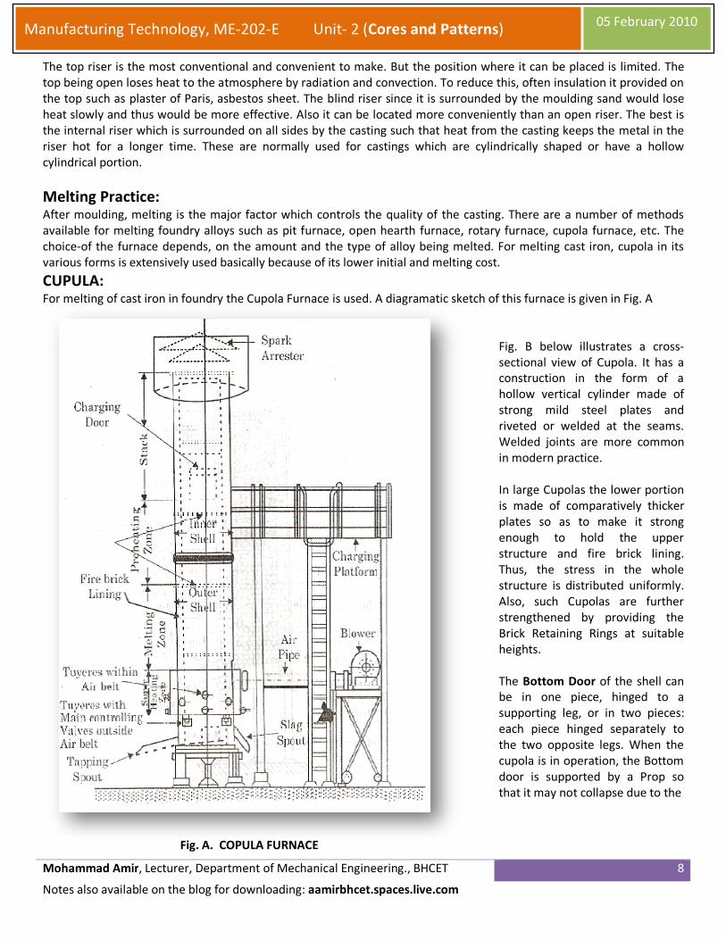
CUPULA: For melting of cast iron in foundry the Cupola Furnace is used. A diagramatic sketch of this furnace is given in Fig. A
Fig. A. COPULA FURNACE
Fig. B below illustrates a cross-
sectional view of Cupola. It has a
construction in the form of a
hollow vertical cylinder made of
strong mild steel plates and
riveted or welded at the seams.
Welded joints are more common
in modern practice.
In large Cupolas the lower portion
is made of comparatively thicker
plates so as to make it strong
enough to hold the upper
structure and fire brick lining.
Thus, the stress in the whole
structure is distributed uniformly.
Also, such Cupolas are further
strengthened by providing the
Brick Retaining Rings at suitable
heights.
The Bottom Door of the shell can
be in one piece, hinged to a
supporting leg, or in two pieces:
each piece hinged separately to
the two opposite legs. When the
cupola is in operation, the Bottom
door is supported by a Prop so
that it may not collapse due to the

Mohammad Amir, Lecturer, Department of Mechanical Engineering., BHCET 9
Notes also available on the blog for downloading: aamirbhcet.spaces.live.com
Manufacturing Technology, ME-202-E Unit- 2 (Cores and Patterns) 05 February 2010
large weight of the charge and coke, etc., it carries. When we do not need the
COPULA for further operation, the charge feeding is stopped, air supply cut
off and the Prop is removed. As soon as the Prop is removed the Door drops
down providing a clear space for the coke fire, residue of the molten metal
with slag and the sand bed to fall down and thus the fire inside ceases
gradually.
Fig. B Cross-sectional view of COPULA Furnace
A Wind Chamber or Wind Belt, as
it is more commonly known,
encircles the cupola shell at a
place little above the bottom of
the shell. This belt is connected to
the furnace blower by means of a
Blast Pipe. The amount of air
required is forced into the
chamber by the blower, which
enters the furnace through
openings called Tuyeres. These
Tuyeres are provided all around
the shell and have a definite
number and size depending upon
the amount of air required.
Charging Door is located at a
suitable height above the charging
platform. This platform is of
robust mild steel construction,
supported on four strong steel
legs, and is provided with a
Ladder. Weighed quantities of
Metal, Coke, Scrap and Flux are
collected on this platform, which
is charged into the COPULA as and
when required.
The top of the COPULA is provided
with a Mesh Screen and a Spark
Arrester. It is a cone shaped
construction, as shown in the
diagram. This attachment
facilitates a free escape of the
waste gases at the same
time deflects the spark and the
dust back into the furnace. In
some COPULAS the upper portion
is made tapered with the top
diameter as about half of the
inside diameter of the cupola at
the smelting zone.
Small Cupola say from 500 kg to
1000 kg capacity, are better
known as Cupolettes. They are
quite self-sufficient in operation
and have almost all the
accessories which a large cupola
possesses except the Spark
Arrester and Charging Door. Since
the height of these Cupolettes is
very small, say 2.5 meters to 4

Mohammad Amir, Lecturer, Department of Mechanical Engineering., BHCET 10
Notes also available on the blog for downloading: aamirbhcet.spaces.live.com
Manufacturing Technology, ME-202-E Unit- 2 (Cores and Patterns) 05 February 2010
meters, charging is done from the top of the Cupolette. They are fixed on two reunions inside the bearings, mounted on
the supporting legs, so that they can be tilted to become horizontal for providing the fire Brick lining. This lining is
provided in all cupolas, irrespective of the size to withstand the high temperature produced inside the furnace.
Other Furnaces: • Reverberatory Furnace:
In these furnaces the fuel burners fire within a refractory hood above the metal bath. These are generally used to
melt large amounts of metal for example, aluminium to supply to holding furnaces such as those used with pressure
die casting machines. These use gas fired burners located generally high in the furnace transferring the heat by
radiation to the walls and roof. As the walls and roof become incandescent they radiate the heat to the metal bath.
These furnaces are simple and have relatively low capital cost. Thus these are generally used for melting large
volumes of metal.
• Crucible Furnace:
Smaller foundries generally prefer the crucible furnace. The crucible is generally heated by electric resistance or gas
flame. In these the metal is placed in a crucible of refractory metal and the heating is done to the crucible thus there
is no direct contact between the flame and the metal charge. This type of melting is very flexible since it suits a
variety of casting alloys. Degassing and any metal treatment can be completed in the crucible before it is removed
for pouring. Melt quality and temperature can also be controlled reasonably well.
• Induction Furnace:
The induction furnaces are used for all types of materials, the chief advantage being the heat source is isolated from
the charge and the slag and flux would be getting the necessary heat directly from the charge instead of the heat
source. The stirring effect of the electric current would cause fluxes to be entrained in the melt if they are mixed
along with the charge. So flux is generally added after switching off the current to the furnace. Then sufficient time
must be allowed for the oxides to be removed by the flux as slag before transferring the metal for pouring. High
frequencies help in stirring the molten metal and thus help in using the metal dwarf (chips). Low cost raw materials
could, therefore, be used and at the same time better control of temperature and composition can be achieved.
Ladles:
The molten metal from the furnace is tapped into the ladles at requisite intervals and then poured into the moulds.
Depending on the amount of metal to be handled, there are different sizes of ladles. They may range between 50 kg to
30 tones depending upon the casting size. For grey cast iron, since the slag can be easily separated, top pouring ladles
would be enough. But for steels; to separate the slag effectively, the metal is to be poured from the bottom with the
help of the bottom pour ladle. The bottom pour ladle has an opening in the bottom that is fitted with a refractory
nozzle. A stopper rod, suspended inside the ladle, pulls the stopper head up from its position thus allowing the molten
alloy to flow from the ladle. As the metal in the ladle loses a large amount of heat to the surrounding atmosphere by
radiation it is necessary to account for this drop in the temperature of the casting metal.
Fettling: The complete process of the cleaning of castings, called 'fettling', involves the removal of the cores, gates and risers,
cleaning of the casting surface and chipping of any of the unnecessary projections on surfaces.
The dry sand cores can be removed simply by knocking off with an iron bar, by means of a core vibrator, or by means of
hydro blasting. The method depends on the size, complexity and the core material used.
The gates and risers can be removed by hammering, chipping, hack sawing, abrasive cutoff or by flame or arc cutting.
Removal of gates and risers can be simplified by providing a reduced metal section at the casting joints. For brittle
materials such as grey cast iron, the gates can easily be broken by hitting with a hammer. For steel and other similar
materials, sawing with any metal cutting saw like hack saw or band saw would be more convenient. For large size gates
and risers, it may be necessary to use flame or arc cutting to remove them. Similarly, abrasive cut off may also be used

Mohammad Amir, Lecturer, Department of Mechanical Engineering., BHCET 11
Notes also available on the blog for downloading: aamirbhcet.spaces.live.com
Manufacturing Technology, ME-202-E Unit- 2 (Cores and Patterns) 05 February 2010
for removal of gates. Most of the abrasive cut off can be carried out by portable grinding machines with an angled
grinding head. Typical wheel speeds used are in the range of 45 to 80 m/s. The casting surface after removal of the gates
may still contain some rough surfaces left at the time of removal of gates, or sand that is fused with the surface, or some
fins and other projections on the surface near the parting line. These need to be cleaned thoroughly before the casting is
put to use. The fins and other small projections may easily be chipped off with the help of either hand tools or
pneumatic tools. For smoothening the rough cut gate edges either the pedestal or swing frame grinder is used
depending on the size of the casting. For cleaning the sand particles sticking to the casting surface, sand blasting is
normally used. The casting is kept in a closed box and a jet of compressed air with a blast of sand grains or steel grit is
directed against the casting surface, which thoroughly cleans the casting surface. The typical shot speeds reached of the
order of 80 m/s. The shots used are either chilled cast iron grit or steel grit. Chilled iron is less expensive but is likely to
be lost quickly by fragmentation. In this operation, the operators mould be properly protected. Another useful method
for cleaning the casting surface is the tumbling. Here the castings are kept in a barrel which is completely closed and
then slowly rotated on a horizontal axis at 30 to 40 rpm. The barrel is reasonably packed, with enough room for castings
to move so that they will be able to remove the sand and unwanted fins and projections. However one precaution to be
taken for tumbling is that, the castings should all be rigid with no frail or overhung segments which may get knocked off
during the tumbling operation.
Defects in Castings: Any irregularity in the moulding process causes defects in castings which may sometimes be tolerated, sometimes
eliminated with proper moulding practice or repaired using methods such as welding and metallization. The following
are the major defects which are likely to occur in sand castings:
• Gas defects.
• Shrinkage cavities.
• Moulding material defects.
• Pouring metal defects.
• Metallurgical defects.
Gas defects: The defects in this category can be classified into blow holes and open blows, air inclusion and pin-hole porosity. All
these defects are caused to a great extent by the lower gas passing tendency of the mould which may be due to lower
venting, lower permeability of the mould and/or improper design of the casting. The lower permeability of the mould is,
in turn, caused by finer grain size of the sand, finer clay, higher moisture, or by excessive ramming of the moulds
Blow holes and open blows: These are the. Spherical, flattened, or elongated cavities present inside the casting or on
the surface as shown in the Fig. On the surface they are called as the open blows and inside, they are called blow holes.
These are caused by the moisture left in the mould and the core. Because of the heat in the molten metal, the moisture
is converted into steam; part of this steam is entrapped in the casting ends up as blow hole or ends up as open holes
when it reaches the surface. Apart from the presence of moisture they occur due to the lower venting and lower
permeability of the mould. Thus in green sand moulds it is very difficult to get rid of the blow holes, unless venting is
provided.
Air inclusions: The atmospheric and other gases absorbed by the molten metal in the furnace, in the ladle, and during
the flow in the mould, when not allowed to escape, would be trapped inside the casting and weaken it. The main
reasons for this defect are the higher pouring temperatures which increase the amount of gas absorbed; poor gating
design such as straight sprues in unpressurised gating, abrupt bends and other turbulence causing practices in the
gating, which increases the air aspiration and finally the low permeability of the mould itself. Remedies would be to
choose the appropriate pouring temperature and improve gating practices by reducing the turbulence.

Mohammad Amir, Lecturer, Department of Mechanical Engineering., BHCET 12
Notes also available on the blog for downloading: aamirbhcet.spaces.live.com
Manufacturing Technology, ME-202-E Unit- 2 (Cores and Patterns) 05 February 2010
Pin Hole Porosity: This is caused by hydrogen in the molten metal. This could have been picked up in the furnace or by
the dissociation of water inside the mould cavity. As the molten metal gets solidified it loses the temperature which
decreases the solubility of gases and thereby expelling the dissolved gases. The hydrogen while leaving the solidifying
metal would cause very small diameter and long pin holes showing the path of escape. These series of pin holes cause
the leakage of fluids under high operating pressures. The main, reason for this is the high pouring temperature which
increases the gas pick-up.
Shrinkage Cavities: These are caused by the liquid shrinkage occurring during the solidification of the castings, to compensate this proper
feeding of liquid metal is required as also proper casting design also has a very large impact towards these sorts of
defects.
Moulding Material defects: Under this category are those defects which are caused because of the characteristics of the moulding materials. The
defects that can be put in this category are: cuts and washes, metal penetration, fusion, run out, rat tails and buckets,
swells and drop. These defects occur essentially because the moulding materials are not of requisite properties or due to
improper ramming.
Cuts and washes: These appear as rough spots and areas of excess metal, and are caused by the erosion of moulding
sand by the blowing molten metal. This may be caused by the moulding sand not having enough strength or the molten
metal flowing at high velocity' The former can be remedied by the proper change of moulding sand and using
appropriate moulding method. The latter can be taken care of by altering the gating design to reduce the turbulence in
the metal, by increasing the size of gates or by using multiple ingates.
Metal penetration: When the molten metal enters the gaps between the sand grains, the result would be a rough
casting surface. The main reason for this is that, either the grain size of the sand is too coarse, or no mould wash has
been applied to the mould cavity. This can also be caused by higher pouring temperatures. Choosing appropriate grain
size, together with a proper mould wash should be able to eliminate this defect.
Fusion: This is caused by the fusion of sand grains with the molten metal, giving a brittle, glassy appearance on the
casting surface. The main reason for this defect is that the clay in the moulding sand is of lower refractoriness or that the
pouring temperature is too high, The choice of an appropriate type and amount of Bentonite would cure this defect.
Run out: A run out is caused when the molten metal leaks out of the mould. This may be caused either due to faulty
mould making or because of the faulty moulding flask.
Shift: A shift is a misalignment between two mating surfaces leaving a small clearance between them and changing their
relative location. This may occur at the parting surface between the two parts of the mould called a Mould shift, or at
the core prints, providing a gap between the core and core seat. This is known as a Core shift. They result in a mismatch
of the casting at the parting line and an incorrect dimension or incorrect location of hole. The clearance left between the
mating surfaces is filled up by the molten metal and is found to be attached to the casting in the form of a thin
projection of metal called Fin. The Mould shift is a result of misalignment of the moulding boxes due to worn out or bent
clamping pins or due to improper alignment of the two halves of the pattern. The core shift is due to improper
supporting of core improper location of core and faulty core boxes producing oversized or undersized cores. The above
shifts may also occur due to improper clamping of boxes and placement of inadequate weights over the cope, resulting
in the lifting of cope.
Rat tails and buckles: Rat tail is caused by the compression failure of the skin of the mould cavity because of the
excessive heat in the molten metal. Under the influence of the heat, the sand expands, thereby moving the mould wall

Mohammad Amir, Lecturer, Department of Mechanical Engineering., BHCET 13
Notes also available on the blog for downloading: aamirbhcet.spaces.live.com
Manufacturing Technology, ME-202-E Unit- 2 (Cores and Patterns) 05 February 2010
backwards and in the process when the wall gives away, the casting surface may have this marked as a small line, as
shown in Fig. With a number of such failures, the casting surface may have a number of crisscrossing small lines. Buckles
are the rat tails which are severe.
The main causes for these defects are: the moulding sand has got poor expansion properties and hot strength or the
heat in the pouring metal is too high. Also, the facing sand applied does not have enough carbonaceous material to
provide the necessary cushioning effect. Proper choice of facing sand ingredients and the pouring temperature are the
measures to reduce the incidence of these defects.
Swell: Under the influence of the metallostatic forces, the mould wall may move back causing a swell in the dimensions
of the casting. As a result of the swell, the feeding requirements of castings increase which should be taken care of by
the proper choice of risering. The main cause of this is the faulty mould making procedure adopted. A proper ramming
of the mould should correct this defect.
Drop: The dropping of loose moulding sand or lumps normally from the cope surface into the mould cavity is
responsible for this defect. This is essentially, due to improper ramming of the cope flask.
Warpage: It is an undesirable deformation in the casting which may occur during or after solidification. The deformation
takes place due to the internal stresses developed in the casting due to differential solidification in different sections.
Such stresses are also developed and differential solidification occurs in case of castings having very large and wide flat
surfaces. Both the causes can be attributed to faulty design of the casting which needs modification to ensure proper
directional solidification.
Pouring metal defects: The likely defects in this category are mis-runs and cold shuts and slag inclusions.
Mis-runs and cold shuts: Mis-run is caused when the metal is unable to fill the mould cavity completely and thus leaves
unfilled cavities. A cold shut is caused when two metal streams while meeting in the mould cavity, do not fuse together
properly, thus causing a discontinuity or weak spot in the casting. Sometimes a condition leading to cold shuts can be
observed when no sharp corners exist in a casting. These defects are caused essentially, by the lower fluidity of the
molten metal or when the section thickness of the casting is too small. The latter can be rectified by proper casting
design. The remedy available is to increase the fluidity of the metal by changing the composition or rising the pouring
temperature. This defect can also be caused when the heat removal capacity is increased such as in the case of green
sand moulds. The castings with large surface area to volume ratio are more likely to be prone to these defects. Further
cause of this defect-is the back pressure due to gases in the mould which is not properly vented. The remedies are
basically improving the mould design.
Slag inclusions: During the melting process, flux is added to remove the undesirable oxides and impurities present in the
metal. At the time of tapping, the slag should be properly removed from the ladle before the metal is poured into the
mould. Otherwise any slag entering the mould cavity will be weakening the casting and also spoil the surface of the
casting. This can be eliminated by some of the slag trapping methods such as pouring basin screens or runner
extensions.
Metallurgical defects: The defects that can be grouped under this category are hot tears and hot spots.
Hot Tears: Since metal has low strength at higher temperatures, any unwanted cooling stress may cause the rupture of
the casting. The mainly cause for this is the poor casting design.

Mohammad Amir, Lecturer, Department of Mechanical Engineering., BHCET 14
Notes also available on the blog for downloading: aamirbhcet.spaces.live.com
Manufacturing Technology, ME-202-E Unit- 2 (Cores and Patterns) 05 February 2010
Hot Spots: These are caused by the chilling of the casting. For example, with grey cast iron having small amounts of
silicon, very hard cast iron may result at the chilled surface. This hot spot will interfere with the subsequent machining of
this region. Proper metallurgical control and chilling practices are essential for eliminating the hot spots.
Assignment for the students: • Write about the various Casting cleaning processes?
• What are the various ways of inspecting a casting?
Last date for the submission of assignment: 23rd
February 2010