Embed Size (px)
Citation preview
Mapping Fundamental Business
Process Modelling Language
to a Semantic Web Based Language
Gayathri Nadarajan
TH
E
U N I V E RS
IT
Y
OF
ED I N B U
RG
H
Master of Science
School of Informatics
University of Edinburgh
2005
Abstract
The need for more sophisticated web-based support tools has become apparent with the fast-
advancement of the World Wide Web and the Semantic Web (Berners-Lee et al., 2001) tech-
nologies. Enterprise Modelling methods, such as Business Process Modelling (BPM) methods,
on the other hand, are more established and have been successfully used in practice for describ-
ing organisational needs. It would therefore be most fitting for the more mature BPM methods
to be extended to Semantic Web Services so as to facilitate communication between appli-
cations and to enable further cooperation between them. This project lays out a conceptual
mapping framework between a formal and visually rich BPM language, Fundamental Busi-
ness Process Modelling Language (FBPML), to the Web Services Ontology (OWL-S), thus
narrowing the gap between Enterprise Modelling methods and Semantic Web Services. The
framework is divided into a data model (ontology) mapping and a process model mapping. An
implementation of the process model mapping is demonstrated, along with a theoretical evalu-
ation of the translated models. Suggestions for improvement and future directions for OWL-S
are also provided.
i

Acknowledgements
I thank most Dr Jessica Chen-Burger for her guidance, generosity and selflessness; without
which this work would not have been possible.
I also thank my family who have always been behind me, Yun Mi Hwang and Angie Sveda
for bringing me out of my shell, all fellow Appleton Tower lab livers and ping-pongers, for the
company in an otherwise dreary place.
Special thanks to Li Wen Kuok, Wai Leng Say and Sunnhild Bertz for being my lifelong inspi-
rations.
Much appreciation also goes to Leonidas Koutsoumpos and Ian Brazil for giving insightful
feedback on the dissertation.
ii

Declaration
I declare that this thesis was composed by myself, that the work contained herein is my own
except where explicitly stated otherwise in the text, and that this work has not been submitted
for any other degree or professional qualification except as specified.
(Gayathri Nadarajan)
iii

Table of Contents
List of Figures vii
List of Tables viii
1 Introduction 1
1.1 Statement of Problem - the Gap . . . . . . . . . . . . . . . . . . . . . . . . . . 1
1.2 The Mapping Approach . . . . . . . . . . . . . . . . . . . . . . . . . . . . . . 2
1.3 Overview and Chapter Organisation . . . . . . . . . . . . . . . . . . . . . . . 3
2 Background 4
2.1 Enterprise and Process Modelling . . . . . . . . . . . . . . . . . . . . . . . . 4
2.2 Emerging technologies for the Semantic Web . . . . . . . . . . . . . . . . . . 5
2.2.1 BPEL4WS . . . . . . . . . . . . . . . . . . . . . . . . . . . . . . . . 6
2.2.2 OWL-S . . . . . . . . . . . . . . . . . . . . . . . . . . . . . . . . . . 6
2.2.3 WSMO . . . . . . . . . . . . . . . . . . . . . . . . . . . . . . . . . . 6
2.3 Fundamental Business Process Modelling Language . . . . . . . . . . . . . . . 7
2.4 OWL-S: The Web Services Ontology . . . . . . . . . . . . . . . . . . . . . . . 8
2.4.1 OWL . . . . . . . . . . . . . . . . . . . . . . . . . . . . . . . . . . . 9
2.4.2 SWRL and SWRL FOL . . . . . . . . . . . . . . . . . . . . . . . . . 10
2.5 Rationale . . . . . . . . . . . . . . . . . . . . . . . . . . . . . . . . . . . . . 11
3 Data Model Mapping 13
3.1 FBPML Data Language . . . . . . . . . . . . . . . . . . . . . . . . . . . . . . 14
3.1.1 Concepts . . . . . . . . . . . . . . . . . . . . . . . . . . . . . . . . . 14
3.1.2 Functions . . . . . . . . . . . . . . . . . . . . . . . . . . . . . . . . . 15
3.1.3 Logical Quantification . . . . . . . . . . . . . . . . . . . . . . . . . . 15
3.1.4 Predicates . . . . . . . . . . . . . . . . . . . . . . . . . . . . . . . . . 15
3.1.5 Meta-predicates . . . . . . . . . . . . . . . . . . . . . . . . . . . . . . 15
3.2 OWL-S Data Language: OWL . . . . . . . . . . . . . . . . . . . . . . . . . . 15
3.2.1 Syntax . . . . . . . . . . . . . . . . . . . . . . . . . . . . . . . . . . 17
iv

3.2.2 Class Elements . . . . . . . . . . . . . . . . . . . . . . . . . . . . . . 17
3.2.3 Instances . . . . . . . . . . . . . . . . . . . . . . . . . . . . . . . . . 17
3.2.4 Property Elements . . . . . . . . . . . . . . . . . . . . . . . . . . . . 17
3.2.5 Property Restrictions . . . . . . . . . . . . . . . . . . . . . . . . . . . 17
3.2.6 Quantification and Cardinality Restrictions . . . . . . . . . . . . . . . 18
3.2.7 Special Properties . . . . . . . . . . . . . . . . . . . . . . . . . . . . . 18
3.2.8 Boolean Combinations . . . . . . . . . . . . . . . . . . . . . . . . . . 18
3.2.9 Data types . . . . . . . . . . . . . . . . . . . . . . . . . . . . . . . . . 18
3.3 Mapping from FBPML DL to OWL . . . . . . . . . . . . . . . . . . . . . . . 19
3.3.1 Mapping of Concepts . . . . . . . . . . . . . . . . . . . . . . . . . . . 19
3.3.2 Mapping of Instances . . . . . . . . . . . . . . . . . . . . . . . . . . . 20
3.3.3 Mapping of Relations . . . . . . . . . . . . . . . . . . . . . . . . . . . 20
3.3.4 Mapping of Datatype Properties . . . . . . . . . . . . . . . . . . . . . 21
3.4 Discussion . . . . . . . . . . . . . . . . . . . . . . . . . . . . . . . . . . . . . 21
4 Process Model Mapping 23
4.1 FBPML Process Components . . . . . . . . . . . . . . . . . . . . . . . . . . . 23
4.1.1 Main Process Model Components . . . . . . . . . . . . . . . . . . . . 23
4.1.2 Additional Primitives . . . . . . . . . . . . . . . . . . . . . . . . . . . 26
4.1.3 FBPML Formal Definition . . . . . . . . . . . . . . . . . . . . . . . . 26
4.2 OWL-S Process components . . . . . . . . . . . . . . . . . . . . . . . . . . . 26
4.2.1 Process . . . . . . . . . . . . . . . . . . . . . . . . . . . . . . . . . . 27
4.2.2 Parameter . . . . . . . . . . . . . . . . . . . . . . . . . . . . . . . . . 29
4.2.3 Result . . . . . . . . . . . . . . . . . . . . . . . . . . . . . . . . . . . 29
4.2.4 Control Constructs . . . . . . . . . . . . . . . . . . . . . . . . . . . . 29
4.2.5 Bindings (DataFlow specifications) . . . . . . . . . . . . . . . . . . . 31
4.2.6 Expression . . . . . . . . . . . . . . . . . . . . . . . . . . . . . . . . 31
4.3 Mapping FBPML PL with OWL-S . . . . . . . . . . . . . . . . . . . . . . . . 32
4.3.1 Mapping of primitives . . . . . . . . . . . . . . . . . . . . . . . . . . 32
4.3.2 Mapping of Typical (Simple) Models . . . . . . . . . . . . . . . . . . 34
4.3.3 Methodology for Process Model Mapping for More Complex Models . 43
4.3.4 Examples of More Complex Models Mapping . . . . . . . . . . . . . . 44
4.4 Discussion . . . . . . . . . . . . . . . . . . . . . . . . . . . . . . . . . . . . . 51
5 Implementation and Analysis 53
5.1 System Architecture . . . . . . . . . . . . . . . . . . . . . . . . . . . . . . . . 53
5.2 Process Model Translator . . . . . . . . . . . . . . . . . . . . . . . . . . . . . 54
5.3 Design . . . . . . . . . . . . . . . . . . . . . . . . . . . . . . . . . . . . . . . 55
v

5.3.1 Typical (Simple) Process Model Translator . . . . . . . . . . . . . . . 56
5.3.2 Complex Process Model Translator . . . . . . . . . . . . . . . . . . . 57
5.3.3 Main Predicates . . . . . . . . . . . . . . . . . . . . . . . . . . . . . . 58
5.4 Theoretical Analysis . . . . . . . . . . . . . . . . . . . . . . . . . . . . . . . 59
6 Conclusions and Future Work 63
6.1 Continued Utilisation of Business Process Technologies . . . . . . . . . . . . . 63
6.2 Recommendations for OWL-S . . . . . . . . . . . . . . . . . . . . . . . . . . 64
6.2.1 Provision forOr control construct . . . . . . . . . . . . . . . . . . . . 64
6.2.2 Complete formalism for rules and conditions . . . . . . . . . . . . . . 64
6.2.3 Combining OWL-S with WSMO . . . . . . . . . . . . . . . . . . . . 64
6.3 Future Work . . . . . . . . . . . . . . . . . . . . . . . . . . . . . . . . . . . . 65
6.3.1 Bidirectional Mapping . . . . . . . . . . . . . . . . . . . . . . . . . . 65
A Appendix 67
A.1 OWL header file . . . . . . . . . . . . . . . . . . . . . . . . . . . . . . . . . . 67
A.2 General syntax for Sequences . . . . . . . . . . . . . . . . . . . . . . . . . . . 68
A.3 General syntax for Split, Split-Join and Choice control constructs . . . . . . . . 69
Bibliography 70
vi

List of Figures
1.1 The FBPML to OWL-S conceptual mapping framework . . . . . . . . . . . . . 3
2.1 The slightly extended Semantic Web layering cake by Berners-Lee . . . . . . . 9
2.2 The rise of three Semantic Web based languages . . . . . . . . . . . . . . . . . 11
4.1 FBPML notation . . . . . . . . . . . . . . . . . . . . . . . . . . . . . . . . . 24
4.2 The OWL-S Process Model ontology (OWL-S 2004). . . . . . . . . . . . . . . 27
4.3 The properties of theResult class. . . . . . . . . . . . . . . . . . . . . . . . . 29
4.4 Process diagram of a sequence of activities in FBPML. . . . . . . . . . . . . . 34
4.5 FBPML And-Joint Junction (with barrier synchronisation). . . . . . . . . . . . 36
4.6 FBPML And-Split Junction (with barrier synchronisation). . . . . . . . . . . . 39
4.7 FBPML Xor-Split Junction. . . . . . . . . . . . . . . . . . . . . . . . . . . . . 41
4.8 FBPML And-And Junction. . . . . . . . . . . . . . . . . . . . . . . . . . . . . 44
4.9 Decomposition of FBPML process model containing the And-And Junction. . . 45
4.10 A complex FBPML process model. . . . . . . . . . . . . . . . . . . . . . . . . 47
4.11 Decomposition of the complex process model. . . . . . . . . . . . . . . . . . . 48
5.1 An architectural overview of FBPML to OWL-S Mapping Engine. . . . . . . . 54
5.2 Main screen shot of program when consulted and queried in SICStus Prolog. . 55
6.1 A bidirectional mapping example; FBPML to OWL-S and OWL-S to FBPML . 66
vii

List of Tables
3.1 FBPML core predicates examples and their descriptions. . . . . . . . . . . . . 16
4.1 Summary of mapping between FBPML and OWL-S primitives . . . . . . . . . 32
5.1 process map.pl: Some general predicates. . . . . . . . . . . . . . . . . . . . 59
5.2 process map.pl: Sequence-specific predicates. . . . . . . . . . . . . . . . . . 59
5.3 process map.pl: Simple Junction-specific predicates. . . . . . . . . . . . . . 59
5.4 process map.pl: Coupled Junction predicates. . . . . . . . . . . . . . . . . . 59
5.5 process map.pl: Complex model predicates. . . . . . . . . . . . . . . . . . . 60
5.6 Analysis of mapping between FBPML and OWL-S data and process model
components. . . . . . . . . . . . . . . . . . . . . . . . . . . . . . . . . . . . . 61
viii

Chapter 1
Introduction
The need for more sophisticated web-based support tools has become apparent with the evolve-
ment and advancement of the World Wide Web and the Semantic Web vision (Berners-Lee
et al., 2001)1. The Semantic Web is an augmentation of the existing web which aims to enable
the interoperability of various dynamic-enhanced capabilities not yet possessed by web appli-
cations today. One key technology is web services, which offer a relatively new and evolving
paradigm for building distributed web applications and are a significant step towards realis-
ing the Semantic Web (Cerami, 2002). For organisations with business goals, the automation
of business processes as web services is increasingly important, especially with many busi-
ness transactions taking place within the web today. The existence of established Enterprise
Modelling (EM) methods, such as Business Process Modelling (BPM) methods suggests that
they could be exploited by emerging technologies such as Semantic Web Services to provide
a more mature framework incorporating both business-specific and web application-specific
technologies. In a wider context this aims to bring business-oriented and technical-oriented
communities closer in order to achieve common organisational goals. In the following section
we provide the motivation for ”bridging this gap” and introduce a method in which this could
be done. We also outline the organisation of the rest of the dissertation.
1.1 Statement of Problem - the Gap
Web services are trendy amongst many business organisations today with the pervasiveness of
the World Wide Web and the advent in web technology. Business-to-Business (B2B) Electronic
Commerce is fast becoming the most important application area of Semantic Web technology
in terms of market volume (Fensel et al., 2003). Thus there is a pressing need to bring both
business and technology together for the realisation of virtual organisations.
1Coined by Tim Berners-Lee, the inventor of the Web and Director of the World Wide Web Consortium (W3C)
1

Chapter 1. Introduction 2
However, a main obstacle in bridging EM methods and web services is the lack of direct
mapping from EM methods to web services. This is to a large extent due to the informal or
semi-formal nature of enterprise modelling methods. Some efforts have been channelled to
overcome this pitfall (BPEL4WS, 2003), (Chen-Burger and Stader, 2003), (Guo et al., 2004)).
In this project we seek to find means to bridge the gap that exists between enterprise modelling
methods and web services by attempting to map a semantic based process modelling language,
Fundamental Business Process Modelling Language (FBPML) (Chen-Burger et al., 2002)2 to
a Semantic Web compliant language, OWL-S (OWL-S, 2003). By narrowing the gap between
EM methods and Semantic Web Services, we hope to provide an opportunity for the former to
be utilised by the latter in order to boost and enrich its development and expansion.
1.2 The Mapping Approach
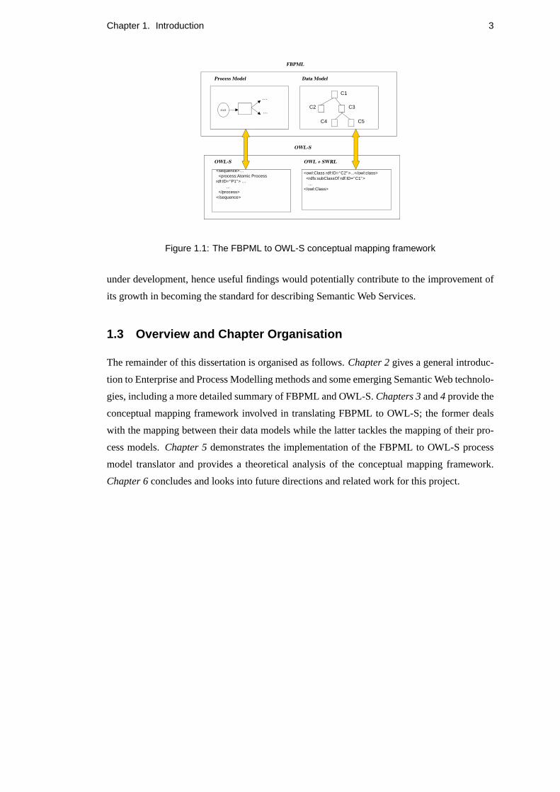
The approach adopted for mapping the two languages is a conceptual mapping framework.
Several closely related work, such as conceptual comparisons and formal mapping procedures
between OWL-S and other technologies, have been conducted recently ((Scicluna et al., 2004),
(Lara et al., 2005)). The motivation for performing a conceptual mapping between FBPML and
OWL-S comes from the fact that both languages have a clear separation between their data and
process schemas. FBPML’s data model is described in the FBPML Data Language while OWL-
S is described in the Web Ontology Language (OWL) (McGuinness and van Harmelen, 2004)
and the Semantic Web Rule Language (SWRL) (Horrocks et al., 2004). FBPML’s process
model is described by the FBPML Process Language while OWL-S contains its own classes to
describe its process model. Thus the mapping framework has been divided into a data model
part and a process model part. Figure 1.1. illustrates this distinction and the general approach
undertaken for this work.
The two clearly defined mapping parts constitute the main essence of this work. We also
demonstrate a simulation of the process model mapping by providing an automated system that
performs a one-way translation from the FBPML process language to the OWL-S process lan-
guage. This implementation is based on the methodology outlined by the conceptual mapping
framework (see Section 4.3.3). We then evaluate the outcome of this mapping exercise in the
aspects of correctness of translation and degree of mapping, i.e. direct, partial or none. As a
result, a critical analysis and justification for the successes and failures of the translated mod-
els are provided. We conclude by probing into the limitations of OWL-S and suggest ways to
improve its structure and representation so that its expressive power would better suit FBPML,
and business process modelling languages in general. This is a timely effort as OWL-S is still
2Artificial Intelligence Applications Institute (AIAI), University of Edinburgh, U.K.
Chapter 1. Introduction 3
FBPML
OWLS
Process Model Data Model
start
…
…
C1
C2 C3
C4 C5
OWL + SWRLOWLS
<sequence>… <process:Atomic Process rdf:ID=“P1”> …
... </process></sequence>
<owl:Class rdf:ID=“C2”>...</owl:class> <rdfs:subClassOf rdf:ID=“C1”> ...</owl:Class>
Figure 1.1: The FBPML to OWL-S conceptual mapping framework
under development, hence useful findings would potentially contribute to the improvement of
its growth in becoming the standard for describing Semantic Web Services.
1.3 Overview and Chapter Organisation
The remainder of this dissertation is organised as follows.Chapter 2gives a general introduc-
tion to Enterprise and Process Modelling methods and some emerging Semantic Web technolo-
gies, including a more detailed summary of FBPML and OWL-S.Chapters 3and4 provide the
conceptual mapping framework involved in translating FBPML to OWL-S; the former deals
with the mapping between their data models while the latter tackles the mapping of their pro-
cess models.Chapter 5demonstrates the implementation of the FBPML to OWL-S process
model translator and provides a theoretical analysis of the conceptual mapping framework.
Chapter 6concludes and looks into future directions and related work for this project.
Chapter 2
Background
This chapter presents the general information that sets the context for the central work that is
described in the proceeding chapters. Firstly it gives an overview of Enterprise and Process
Modelling methods, followed by an introduction to several cutting edge Semantic Web tech-
nologies. Then it gives an overview of the two languages selected for the manipulation of this
work (FBPML and OWL-S) and provides a rationale for choosing OWL-S as the Semantic
Web based language over its competitors.
2.1 Enterprise and Process Modelling
Enterprise Modelling (EM) methods are mature, established procedures that are commonly
used as an analysis tool for describing and redesigning businesses by entrepreneurs. The goal
of applying an enterprise modelling method is to seek ways to improve an organisation’s effec-
tiveness, efficiency and profitability. EM methods are typically informal or semi-formal. They
provide notations which enable entrepreneurs to describe aspects of their business operations.
The notation is normally complemented with semi-formal or natural language descriptions
which allows details of the business operations to be described. Thus EM methods have been
recognised for their value in providing a more organised way to describe complex, informal
domain.
Many EM methods have emerged to describe and redesign businesses, namely business
process modelling, business system modelling and organisational context modelling methods
(Chen-Burger and Robertson, 2004). Business Process Modelling (BPM) methods are able
to formally express informally practised procedures. More importantly, actions and effects of
these processes can be demonstrated using simulation techniques. Some examples of business
process modelling (BPM) methods representations include Process Specification Language
(PSL) (Schlenoff et al., 1997), Integration DEFinition Language (IDEF3) (Mayer et al., 1995),
4

Chapter 2. Background 5
extended UML’s Activity Diagram (Rumbaugh et al., 1998) and Petri-Nets (Reisig, 1985).
In the course of half a decade ago, new process languages and models have been devel-
oped to promote the understanding and interoperability ofprocess semanticsover the Web,
with the extensibility of operating over the Semantic Web. They are characterised by XML and
XML-based languages, such as the Resource Description Framework (RDF) (Klyne and Car-
roll, 2004) and the Web Ontology Language (OWL). Some of these languages include Business
Process Execution Language for Web Services (BPEL4WS), Business Process Modelling Lan-
guage (BPML), Web Service Ontology (OWL-S), and more recently, Web Services Modelling
Ontology (WSMO).
2.2 Emerging technologies for the Semantic Web
The Semantic Web is a collaborative effort led by the World Wide Web Consortium (W3C)1
with participation from a large number of researchers and industrial partners. Since its in-
troduction, the Semantic Web has become the buzzword among communities across many
related disciplines; from knowledge engineers to human-computer specialists to business en-
trepreneurs. It is envisioned to be an extension of the current web, in which information is
annotated with meaning, so as to provide for better machine-processability and automated rea-
soning. Such provision, ultimately, would enable better cooperation between computers and
people (Berners-Lee et al., 2001).
One key technology to the Semantic Web initiative is web services. The static World Wide
Web allows interaction between the user and applications, web services allow applications to
connect to other applications. Therefore, web services enable business paradigms to move from
Business to Consumer-based (B2C) to Business to Business-based (B2B). They represent the
future way of doing business and research (e.g. e-Commerce, e-Science and Grid). The goal of
Semantic Web Services then is to provide an ”intelligent” support (and automation, if possible)
for aspects such as service discovery, selection, composition, simulation, validation, execution,
monitoring and auditing.
Another interesting area that has emerged and flourished in the past decade is the field of
ontological engineering (Gomez-Perez et al., 2003). In line with the aims of the Semantic Web
to provide more explicit representation and support for automated reasoning, ontologies help
a knowledge engineer better reason about a domain by providing precise conceptualisations.
Ontologies are widely used in knowledge management and engineering, e-commerce, infor-
1http://www.w3.org/

Chapter 2. Background 6
mation retrieval and also in the newly emerging Semantic Web. More details on ontologies are
provided in Chapter 3.
Since the Semantic Web is a cutting edge research area, some emerging technologies and
standards are being developed to realise it. Three key competing technologies that have been
selected for discussion here - BPEL4WS, OWL-S and WSMO.
2.2.1 BPEL4WS
Business Process Execution Language for Web Services (BPEL4WS, 2003) is an industrial
effort2 which is a formal specification that models the behavior of web services in business
processes. By doing so, it extends the web services interaction model and enables it to sup-
port business transactions. It defines an interoperable integration model that should facilitate
the expansion of automated process integration within corporations and in business-to-business
spaces.
BPEL4WS builds on and extends XML and web services specifications. The BPEL4WS
process model is layered on top of several XML specifications, is expressed entirely in XML,
uses and extends Web Services Description Language (WSDL) (Christensen et al., 2001), and
uses WSDL and XML Schema for the data model. All external resources and partners are rep-
resented as WSDL services. Heavily influenced by WSDL, BPEL4WS provides extensibility
to accommodate future versions of these standards. In short, a BPEL4WS business process
definition can be thought of as a template for creating business process instances.
2.2.2 OWL-S
OWL-S (OWL-S, 2003)3 is a web service ontology written in OWL (McGuinness and van
Harmelen, 2004) and, more recently, Semantic Web Rule Language (SWRL) (Horrocks et al.,
2004). It provides a core set of mark-up constructs for describing service properties and capa-
bilities in unambiguous, computer-interpretable forms. It provides a language for describing
Web Services as discussed further in section 2.4. This technology is fast becoming thede facto
standard for describing web services as recommended by the W3C and has been the language
of choice for the purpose of this project.
2.2.3 WSMO
Web Services Modelling Ontology (WSMO) (Lausen et al., 2005b), is a recent initiative that
aims to provide an ontology for the description of Semantic Web Services with the intention
2Contributors include IBM, BEA Systems, Microsoft, SAP AG, Siebel Systems3formerly known as DARPA Agent Markup Language (DAML-S)
Chapter 2. Background 7
that it will become the global standard. Its main modelling elements are Ontologies, Goals,
Web Services and Mediators and is described in the Web Service Modeling Language (WSML)
(Lausen et al., 2005a). WSMO also has the aim of building editing tools and reference imple-
mentation. Current effort ((Lara et al., 2005), (Scicluna et al., 2004), (Paolucci et al., 2004))
has been focused on comparing WSMO to OWL-S, with the intention of incorporating the two
technologies together. A discussion on this is provided in Chapter 6.
2.3 Fundamental Business Process Modelling Language
The Fundamental Business Process Modelling Language (FBPML) (Chen-Burger et al., 2002)
was designed to support today’s ever changing workflow environment and that meets diversi-
fied requirements. It is an integration of concepts from several standard modelling languages
including IDEF3 (Mayer et al., 1995), PSL (Schlenoff et al., 1997), PIF (Lee et al., 1998), Com-
monKADS CML (Waern et al., 1993), IBM’s Business System Development Method (BSDM,
1992) and RAD (Ould, 1995). In particular, FBPML adapts and merges two of these modelling
languages, PSL and IDEF3. PSL provides formal semantics for process modelling concepts but
does not provide visual notations or model development methods. IDEF3, on the other hand,
provides visual notations and a rich modelling method, but its semantics is informal. FBPML
merges the visual capabilities of IDEF3 and the formal specification for semantics and theories
provided by PSL. As a result, FBPML is an inherited, specialised and combined version of
these standard modelling languages.
However, as with most BPM languages, FBPML could not be used directly with software
systems, including web services. To work around this problem, FBPML could be incorporated
in a workflow system. A workflow is defined as
”The automation of a business process, in whole or part, during which documents,information or tasks are passed from one participant to another for action, accord-ing to a set of procedural rules (Fischer, 2001).”
The main aim of FBPML is to provide support for virtual organisations, which are be-
coming more and more pervasive with the advancement of web technology and services. It
ultimately seeks to provide distributed knowledge- and semantic-based manipulation and col-
laboration. Most importantly, people with different responsibilities and capabilities could work
together to accomplish tasks and goals without technological or communication barriers caused
by the differences in their roles.
FBPML has been applied successfully in several projects and tools, such as Knowledge
Based Support Tool for Business Models (KBST-EM)4, Knowledge Based Support Tool for En-
4AIAI, University of Edinburgh, U.K.

Chapter 2. Background 8
terprise Models (KBST-BM)5 and Advanced Knowledge Technologies (AKT)6. The FBPML
Graph tool (Kartsouni-Fourli, 2004) is an application that creates and verifies FBPML data
and process models. Some characteristics of FBPML that make it ideal for semantic based
workflow are (Chen-Burger et al., 2002):
• Contains process and data (ontology description) modelling languages.
• Provides an abstraction that is separated from the actual implementation.
• Has precise execution semantics (that is grounded in data semantics) thatsupports generations of a workflow virtual machine at run time (this is dif-ferent from many existing BPMs).
• Provides a visual presentation of the process model that is different frommany existing process modelling languages (PML).
• Provides a visual presentation for the underlying ontology (most BPMLs andPMLs do not have this). Visual data modelling languages may be Entity-Relationship, UML Data Diagram, etc.
• Has a notion of time that may be synchronised.
• Suitable for a distributed environment.
• Is knowledge based, therefore methods and data are grounded by ontology.
• Can be linked to an organisation, business or goal model.
• Provides a suitable foundation for automatic validation & verification, modelcritiquing, inferencing (e.g. dependencies), confirming with ontology, plan-ning, scheduling, etc.
FBPML can express business processes in conventional first order predicate logic. It has two
sections to provide theories and formal representations for describing processes and data, the
Data Language and Process Language, described in more detail in Chapters 3 and 4. The main
notations and formal definitions are provided in Section 4.1.
2.4 OWL-S: The Web Services Ontology
OWL-S is a web service ontology which supplies web service providers with a core set of
markup language constructs for describing the properties and capabilities of their web services
in an unambiguous, computer-intepretable form (OWL-S, 2003). Two other competitors to
OWL-S are briefly introduced in Section 2.2. OWL-S markup of web services facilitates the
automation of web service tasks, including automated web service discovery, execution, com-
position and interoperation. Following the layered approach to markup language development,
the current version of OWL-S builds on OWL, which in turn, is built on top of the Resource
Description Framework (RDF) (Klyne and Carroll, 2004), which is an XML-based data model.
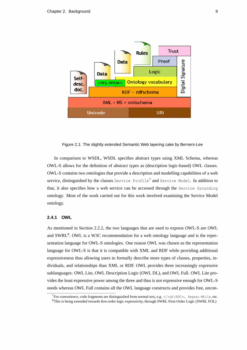
Figure 2.1 illustrates this layering approach.
5AIAI, University of Edinburgh, U.K.6AIAI, University of Edinburgh and collaborators
Chapter 2. Background 9
Figure 2.1: The slightly extended Semantic Web layering cake by Berners-Lee
In comparison to WSDL, WSDL specifies abstract types using XML Schema, whereas
OWL-S allows for the definition of abstract types as (description logic-based) OWL classes.
OWL-S contains two ontologies that provide a description and modelling capabilities of a web
service, distinguished by the classesService Profile7 andService Model. In addition to
that, it also specifies how a web service can be accessed through theService Grounding
ontology. Most of the work carried out for this work involved examining the Service Model
ontology.
2.4.1 OWL
As mentioned in Section 2.2.2, the two languages that are used to express OWL-S are OWL
and SWRL8. OWL is a W3C recommendation for a web ontology language and is the repre-
sentation language for OWL-S ontologies. One reason OWL was chosen as the representation
language for OWL-S is that it is compatible with XML and RDF while providing additional
expressiveness thus allowing users to formally describe more types of classes, properties, in-
dividuals, and relationships than XML or RDF. OWL provides three increasingly expressive
sublanguages: OWL Lite, OWL Description Logic (OWL DL), and OWL Full. OWL Lite pro-
vides the least expressive power among the three and thus is not expressive enough for OWL-S
needs whereas OWL Full contains all the OWL language constructs and provides free, uncon-
7For convenience, code fragments are distinguished from normal text, e.g.</rdf:RDF>, Repeat-While, etc.8This is being extended towards first-order logic expressivity, through SWRL First-Order Logic (SWRL FOL)
Chapter 2. Background 10
strained use of RDF constructs but is undecidable. OWL DL provides maximum expressive-
ness while retaining computational completeness and decidability and thus lays the foundation
for efficient reasoning support for the Semantic Web9. Although the OWL adds considerable
expressive power to the Semantic Web it does have expressive limitations, particularly with
respect to what can be said about properties. Therefore an extension to OWL that overcomes
many of these limitations has been proposed, as discussed in the following subsections.
2.4.2 SWRL and SWRL FOL
The Semantic Web Rule Language (SWRL) (Horrocks et al., 2004) is a Horn clause rules ex-
tension to OWL that provides it with more expressive power when expressing rules and axioms.
It is a rule language that combines OWL with the rule markup language (RuleML, 2005) pro-
viding a rule language compatible with OWL. SWRL provides expressions that may be used
in OWL-S preconditions, process control conditions (such asIf-Then-Else), and in effects
expressions. SWRL expressions may also mention process inputs and outputs as variables thus
linking the two languages together. It comes in several syntaxes; abstract (human-friendly) and
XML/RDF concrete (machine-readable). The OWL-S use of SWRL remains in OWL DL (by
quoting SWRL rules and thus considering them to be XML Literals). This connection with
SWRL makes the OWL-S ontologies more powerful since it uses the expressive power of rules
in a potential emerging standard. It also serves as an example of how one can use a rule lan-
guage and stay within OWL DL, thus preserving efficient reasoning options.
However, the authors of SWRL have demonstrated that the language is undecidable. This
undecidability is mainly caused by allowing existential quantification in the head of the rule
(inherited from OWL), combined with chaining variables over predicates (inherited from Horn
logic) (Lara et al., 2005). A recent initiative is to extend this formalismtowardsfirst-order
logic, in Semantic Web Rule Language First-Order Logic (SWRL FOL) (Patel-Schneider,
2005). SWRL-FOL extends SWRL by adding the standard logical connectives such as nega-
tion and disjunction from first order logic (FOL) which allows certain additional ontologies or
knowledge bases to be formally expressed. It also extends the set of OWL axioms to include an
axiom for arbitrary first-order formula over unary and binary predicates. It presently comes in
abstract and XML concrete syntax. However, its use within OWL-S has not been made explicit,
and this poses uncertainty for those who wish to use it.
9Any discussion on OWL hereafter refers to OWL DL, unless explicitly stated otherwise
Chapter 2. Background 11
2.5 Rationale
Several reasons have contributed to the selection of OWL-S over BPEL4WS and WSMO for
the purpose of this work, although all three technologies are being rapidly developed to operate
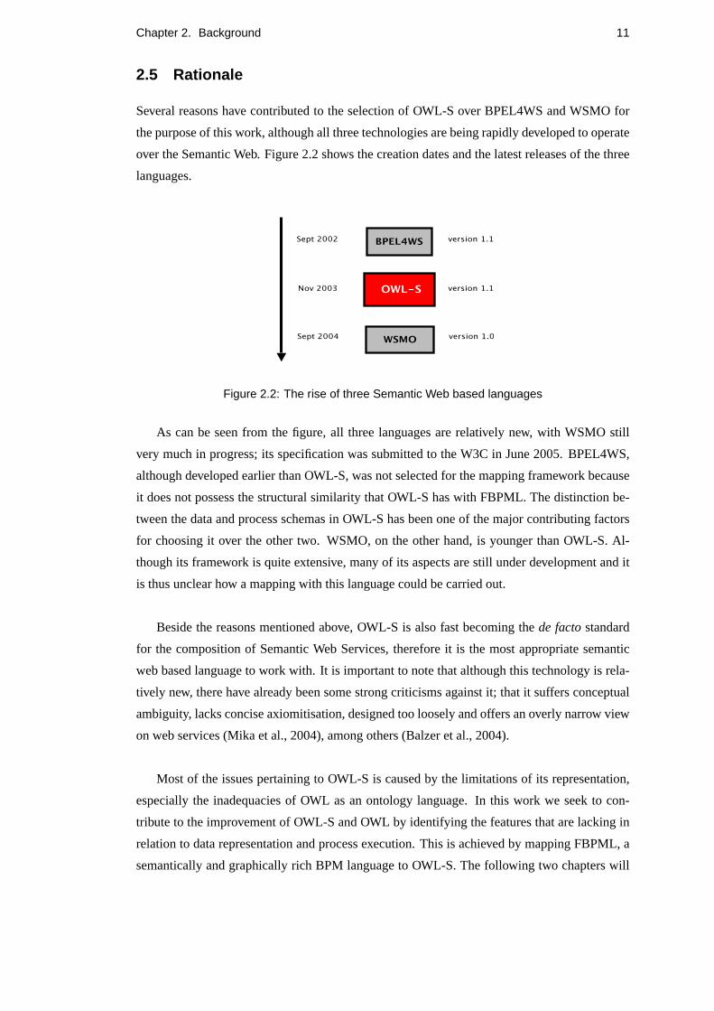
over the Semantic Web. Figure 2.2 shows the creation dates and the latest releases of the three
languages.
Figure 2.2: The rise of three Semantic Web based languages
As can be seen from the figure, all three languages are relatively new, with WSMO still
very much in progress; its specification was submitted to the W3C in June 2005. BPEL4WS,
although developed earlier than OWL-S, was not selected for the mapping framework because
it does not possess the structural similarity that OWL-S has with FBPML. The distinction be-
tween the data and process schemas in OWL-S has been one of the major contributing factors
for choosing it over the other two. WSMO, on the other hand, is younger than OWL-S. Al-
though its framework is quite extensive, many of its aspects are still under development and it
is thus unclear how a mapping with this language could be carried out.
Beside the reasons mentioned above, OWL-S is also fast becoming thede factostandard
for the composition of Semantic Web Services, therefore it is the most appropriate semantic
web based language to work with. It is important to note that although this technology is rela-
tively new, there have already been some strong criticisms against it; that it suffers conceptual
ambiguity, lacks concise axiomitisation, designed too loosely and offers an overly narrow view
on web services (Mika et al., 2004), among others (Balzer et al., 2004).
Most of the issues pertaining to OWL-S is caused by the limitations of its representation,
especially the inadequacies of OWL as an ontology language. In this work we seek to con-
tribute to the improvement of OWL-S and OWL by identifying the features that are lacking in
relation to data representation and process execution. This is achieved by mapping FBPML, a
semantically and graphically rich BPM language to OWL-S. The following two chapters will

Chapter 2. Background 12
demonstrate the conceptual mapping framework (illustrated by Figure 1.1) in more detail.
Chapter 3
Data Model Mapping
A data model describes how the relevant facts pertaining to a specific application are related
logically, namely the concepts, instances, relations between them and their properties. An on-
tology is asemanticallyenhanced data model; apart from providing a means for representation,
they also provide support for reasoning about the entities in a domain. A well known definition
for ontology is given by (Gruber, 1993), then slightly modified by (Borst, 1997):
”Ontologies are defined as a formal specification of a shared conceptualisation.”
Ontologies that are taxonomies orlightweightare distinguished fromheavyweightontologies
that model the domain in a deeper way and provide more restrictions on domain semantics
(Gomez-Perez et al., 2003). Lightweight ontologies include concepts, instances, relationships
between concepts and properties that describe concepts, whereas heavyweight ontologies add
axioms and constraints to the lightweight ontologies. Since both the data models of FBPML
and OWL-S are ontology-driven, the terms data model and ontology can be used interchange-
ably in this context, thus the data model mapping is equivalent to the ontology mapping be-
tween the two specifications1.
An ontology is used as a means for providing a shared understanding of common domains
and to promote reusability. However, in distributed environments such as the web, many differ-
ent ontologies for the same or similar domain have emerged, thus sparking a need for ontology
sharing. In order for ontologies to have maximum impact, they need to be widely shared. They
also need to be re-used in order to minimize the intellectual effort involved in developing them.
For example, one might wish to adopt a date ontology from one source and a physical location
ontology from another and then extend the notion of location to include the time period during
which it holds.
1The termsdata modelandontologyare used interchangeably hereafter.
13

Chapter 3. Data Model Mapping 14
This section illustrates the mapping of data models between FBPML and OWL-S which
involves the translation of concepts (classes), instances (of the concepts) and relations from one
language to the other. The data models are represented in FBPML Data Language (FBPML
DL)(Chen-Burger, 2002) for FBPML and OWL for OWL-S. This mapping primarily involves
translation of concepts, instances and relations from FBPML DL to OWL. It also entails the
translation of properties, such as transitivity and symmetry, of the applicable classes.
The procedure for data model mapping could be summarised in the following steps adopted
from (Scicluna et al., 2004):
1. Pre-processing (if any). E.g. organise file into Prolog readable syntax.
2. Mapping of ontologies.
- Mapping of concepts.
- Mapping of instances.
- Mapping of relations (between concepts).
- Mapping of properties (of concepts).
3. Mapping for rules/axioms (applicable forheavyweightontologies).
3.1 FBPML Data Language
The FBPML Data Language (FBPML DL) (Chen-Burger, 2002) is first-ordered. The syntac-
tic convention that has been used in Prolog has been adopted for its representation. The four
main parts that constitute FBPML DL are the foundational model, the core data language, the
extension data language and the meta-predicates of FBPML. The foundational model includes
the use of logic and set theory to represent concepts, primitive predicates and functions (rela-
tions) and mathematical theory on the manipulation of integer, rational and real numbers. The
core data language includes the fundamental predicates and functions that are common to all
applications of the language while the extension data language contains predicates and func-
tions that are additional to the core data language. They are usually user-defined and are often
application and domain-specific. Meta-predicates give definitions for other predicates and may
define axioms of an application model. The following subsections define the components of
FBPML DL in Prolog syntactic convention.
3.1.1 Concepts
Concepts in the Foundational Model include the classes of things that could occur in a context
or domain in question. The concepts include numbers, variables, constants, lists, strings and

Chapter 3. Data Model Mapping 15
terms.
3.1.2 Functions
Functions in FBPML DL include those that evaluate boolean expressions, such as if a term is
an atom, atomic, a compound or a list. There are functions that manipulate logical expressions
such asnotandor, as well as arithmetic boolean expressions, such as the symbolic representa-
tions of equals, greater than, less than and their variations.
3.1.3 Logical Quantification
FBPML provides for full first order logic expressiveness whereby quantification play an impor-
tant role in determining the scope of the variables within a statement. Quantification expres-
sions includeforall andexist. Constantstrue andfalsealso provide for conditions that remain
always true and false, respectively.
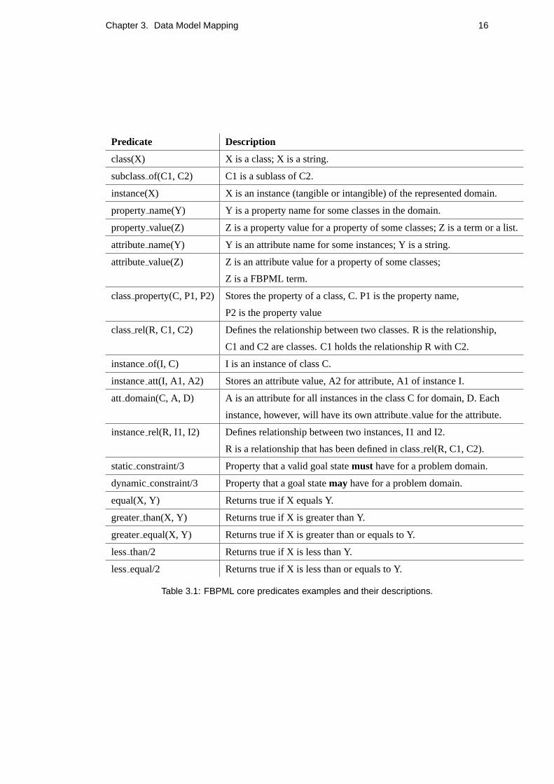
3.1.4 Predicates
The core predicates for the data language include classes, subclasses, instances, attributes,
properties constraints and relations; some which have been represented symbolically as func-
tions (Section 3.1.2), such as boolean arithmetic functionsequal, greater than, lessequaland
so on. Below is the table of the main predicates contained within the FBPML Data Language:
3.1.5 Meta-predicates
Meta-predicates define additional predicates to the core data language. Two such predicates in-
cludedef predicate(Pred, Def) andaxiom(Conclusion, Hypothesis). Def predicate
introduces anewpredicate,Pred and its definition,Def from exisitng predicates, whileaxiom
defines properties ofexistingpredicates; ifHypothesis is true, thenConclusion is true.
3.2 OWL-S Data Language: OWL
As mentioned previously, OWL can be used in conjunction with OWL-S to provide a method to
describe its data. The Web Ontology Language (OWL) was developed to allow users to write
explicit, formal conceptualisations of domain models. The main requirements for ontology
languages that is aimed by OWL are possessing a well-defined syntax and formal semantics,
providing efficient reasoning support and containing sufficient expressive power (Antoniou and
vanHarmelen, 2004). The main reason for defining such a language is to overcome the lim-
itations of RDF Schema which does not express properties such as disjointness, intersection,
union, complement, cardinality restrictions and special characteristics of properties such as
Chapter 3. Data Model Mapping 16
Predicate Description
class(X) X is a class; X is a string.
subclassof(C1, C2) C1 is a sublass of C2.
instance(X) X is an instance (tangible or intangible) of the represented domain.
propertyname(Y) Y is a property name for some classes in the domain.
propertyvalue(Z) Z is a property value for a property of some classes; Z is a term or a list.
attributename(Y) Y is an attribute name for some instances; Y is a string.
attributevalue(Z) Z is an attribute value for a property of some classes;
Z is a FBPML term.
classproperty(C, P1, P2) Stores the property of a class, C. P1 is the property name,
P2 is the property value
classrel(R, C1, C2) Defines the relationship between two classes. R is the relationship,
C1 and C2 are classes. C1 holds the relationship R with C2.
instanceof(I, C) I is an instance of class C.
instanceatt(I, A1, A2) Stores an attribute value, A2 for attribute, A1 of instance I.
att domain(C, A, D) A is an attribute for all instances in the class C for domain, D. Each
instance, however, will have its own attributevalue for the attribute.
instancerel(R, I1, I2) Defines relationship between two instances, I1 and I2.
R is a relationship that has been defined in classrel(R, C1, C2).
static constraint/3 Property that a valid goal statemust have for a problem domain.
dynamicconstraint/3 Property that a goal statemay have for a problem domain.
equal(X, Y) Returns true if X equals Y.
greaterthan(X, Y) Returns true if X is greater than Y.
greaterequal(X, Y) Returns true if X is greater than or equals to Y.
lessthan/2 Returns true if X is less than Y.
lessequal/2 Returns true if X is less than or equals to Y.
Table 3.1: FBPML core predicates examples and their descriptions.

Chapter 3. Data Model Mapping 17
transitivity, symmetry and inverse. One flavour of OWL, OWL DL, has been chosen to form
the basis for the semantic web standard ontology language as it is a compromise between a lan-
guage with sufficient expressive power and reasoning support. Often, the more expressive the
language, the less efficient it is at providing reasoning support, as it becomes less computable,
as possessed by OWL Full.
3.2.1 Syntax
OWL builds on RDF and RDF Schema and uses RDF’s XML-based syntax. Since such syntax
is generally not easy to read, some more intuitive syntactic forms for OWL have been intro-
duced. These include an abstract syntax, a graphical syntax based on the conventions of UML
and an XML-based syntax that does not follow the RDF-style conventions. The subsequent
subsections provide a quick reference for some of the main constructs in OWL (Antoniou and
vanHarmelen, 2004).
3.2.2 Class Elements
Classes are defined using theowl:Class element. Section 3.3.1 contains an example of how a
class is defined in OWL. There are two predefined classes,owl:Thing, which defines the most
general class that contains everything, andowl:Nothing, which is the empty class. Hence,
every class is a subclass ofowl:Thing and a superset ofowl:Nothing.
3.2.3 Instances
Instances, as in FBPML and many conventional programming languages, are actual occur-
rences of the classes or objects that in turn represent an abstraction for them. Instances in
OWL are declared in RDF. Section 3.3.2. provides the syntax for instances expressed in OWL.
3.2.4 Property Elements
Two kinds of properties are relevant to OWL; object properties and data type properties. An
object property relates (all) instances of a class to (all) instances of another class while a data
type property relates (all) instances of a class to datatype values, such as integers, strings and
so on. Sections 3.3.3 and 3.3.4. contain the syntax for object property and data type property
in OWL.
3.2.5 Property Restrictions
One can specify constraints or restrictions on properties using therdfs:subClassOf element.
In general, anowl:Restriction element contains anowl:onProperty element and one or
more restriction declarations. An example depicting the restriction that ”Course A is taught by
Chapter 3. Data Model Mapping 18
lecturer b” is as follows:
<owl:Class rdf:about="#courseA">
<rdfs:subClassOf>
<owl:Restriction>
<owl:onProperty rdf:resource="#isTaughtBy"/>
<owl:hasValue rdf:resource="#b"/>
</owl:Restriction>
</rdfs:subClassOf>
</owl:Class>
3.2.6 Quantification and Cardinality Restrictions
The elementsowl:allValuesFrom andowl:someValuesFrom provide for logicaluniversal
andexistentialquantification respectively. However, the notion of quantification within OWL
is still limited and is being extended by logical formalisms such as SWRL. Cardinality restric-
tions can also be expressed using similar conventions for property restrictions, the restriction
declaration would containowl:minCardinality and/orowl:maxCardinality elements to
define the range of cardinality allowed.
3.2.7 Special Properties
Some properties that are often useful to be expressed in any system that supports automated
reasoning are transitivity, symmetry and inverse. These properties can be expressed directly in
OWL using the elementsowl:TransitiveProperty, owl:SymmetricProperty andowl:in-
verseOf, respectively.
3.2.8 Boolean Combinations
Union, intersection and complement of classes are some binary relations that can be expressed
directly in OWL-S using the constructsowl:unionOf, owl:intersectionOf andowl:com-
plementOf elements. Other boolean combinations are also possible. For example, if we want
to express that ”a is disjoint with b”, the following syntax could be used:
<owl:Class rdf:about="#a">
<owl:disjointWith rdf:ID="#b"/>
</owl:Class>
3.2.9 Data types
OWL does not have any predefined data types, but it allows one to use XML Schema’s prede-
fined data types. Although XML Schema provides for a mechanism to construct user-defined

Chapter 3. Data Model Mapping 19
data types, these cannot be used in OWL. Furthermore, only some of the predefined data types
can be used in OWL, such as string, integer, Boolean, time and date. Thus it could be argued
that the use of data types within OWL is still limited.
3.3 Mapping from FBPML DL to OWL
Since the underlying languages for OWL and FBPML DL differ, a mapping is first needed
between them in order to reuse more complex expressions and the domain ontologies refer-
enced. A mapping of how the two languages correspond are provided in this section. OWL is
an RDF (which is based on XML) based language which utilises tags and tree-like structures
for its representation; whereas FBPML DL is first-ordered. In the following section, syntax for
concepts, instances and relations in FBPML DL and their corresponding translations in OWL
(if any) are provided.
3.3.1 Mapping of Concepts
1. Concrete Class
FBPML DL:
concrete class(Name, Description, Example, Rules, CrossReferences, ObjectAttributes).
e.g. concrete class(myClass, ’A comment’, Example, Rules, CrossReferences, Object-
Attributes).
OWL:
A concrete class in OWL-S has the following (basic) syntax:
<owl:Class rdf:ID="myClass">
<rdfs:comment>A comment</rdfs:comment>
</owl:Class>
2. Abstract Class
FBPML DL:
abstract class(Name, Description, Example, Rules, CrossReferences, ObjectAttributes).
e.g. abstract class(abstractBookBuy, ’A comment’, Example, Rules, CrossReferences,
ObjectAttributes).
OWL:
An abstract class of the example provided above has the following (basic) syntax in OWL-S :
<owl:Class rdf:ID="abstractBookBuy">
<rdfs:comment>A comment</rdfs:comment>
</owl:Class>

Chapter 3. Data Model Mapping 20
Note that FBPML DL distinguishes between concrete and abstract classes (for modelling pur-
poses), but OWL does not have this distinction.
3.3.2 Mapping of Instances
Instances or individuals (in OWL terms) are actual entities of a class.
FBPML DL:
instance(Name, ParentName).
e.g.instance of("949318", lecturer).
OWL:
The same instance described in FBPML example above can be translated to an OWL individual
in the following syntax:
<Lecturer rdf:ID="949318" />
Where the classLecturer has been defined (as in Section 3.3.1).
3.3.3 Mapping of Relations
Relations can be divided into several types. In FBPML, relationships between classes are
distinguished from relationships between instances. OWL-S distinguishes object (instance-to-
instance) and datatype (instance-to-datatype) properties. The FBPMLclass rel/3 predicate
corresponds to theowl:ObjectProperty element in OWL.
FBPML DL:
class rel(Relation, Class 1, Class 2).
Example:Classa has relationshiprel1 with classb.
class rel(rel1, a, b).
OWL:
Therel1 relation above is declared as an object property before it is used. The translated OWL
syntax is as follows:
<owl:ObjectProperty rdf:ID="rel1">
<rdfs:domain rdf:resource="#a"/>
<rdfs:range rdf:resource="#b"/>
</owl:ObjectProperty>
The elementsrdfs:domain andrdfs:range specify the class of those resources that may
appear as subjects and values in a triple with with predicaterel1, which are classesa and
b, respectively. Note that OWL-S describes the term ”instance” as all instances of a class,
while FBPML distinguishes an instance relation from a class relation by providing separate
predicates for each (class rel/3 andinstance rel/3).

Chapter 3. Data Model Mapping 21
3.3.4 Mapping of Datatype Properties
Datatype properties relate classes to types, such as strings, integers, etc. In OWL, all these
datatypes are defined in their respective URIs. The FBPMLclass property/3 predicate
corresponds to theowl:DatatypeProperty element in OWL-S.
FBPML DL:
class property(Class, Property name, Property value).
e.g.class property(academicStaff, teaches, ’Course B’).
OWL:
The ’teaches’ Datatype property, could be expressed in OWL-S as follows:
<owl:DatatypeProperty rdf:ID="teaches">
<rdfs:domain rdf:resource="#academicStaff"/>
<rdfs:range rdf:resource="&xsd;string"/>
</owl:DatatypeProperty>
Note that in OWL-S, theowl:DatatypeProperty element defines the range of the prop-
erty to be of a valid datatype. In this case, ’Course B’ is taken to be of typestring (denoted by
the Uniform Resource Identifier (URI) for the XML Schema predefined string,&xsd;string,
which is equivalent tohttp://www.w3.org/2001/XMLSchema#string). FBPML DL’s class -
property can contain a constant value or a a list of values (see Table 3.1 for further clarification
on its syntax and semantics).
3.4 Discussion
From performing the conceptual mapping between FBPML DL and OWL, it can be seen that
concepts and instances described in FBPML DL can be mapped relatively directly to OWL.
This is due to the similarity in the construction of their underlying languages. OWL is built on
the foundation of (description) logic, thus essentially the concepts and instances that are de-
scribed in first order logic (which is the basis for FBPML DL), are transformed to RDF-based
OWL tags. Although the tags themselves do not resemble first order predicate logic or Prolog
predicates, the OWL/RDF elements do correspond to the predicates described in FBPML DL,
making the translation procedure straightforward in that the predicates and their values can be
enclosed in OWL/RDF tags without further manipulation.
For relations and properties, however, the mapping procedure is slightly more complicated,
as FBPML DL does not have a separate predicate to explicitly describe a particular relation
or property, whereas OWL provides elements to differentiate between object and data type
properties. Thus, to perform the translation, one has to extract the property names from the
class or instance property. In FBPMLclass property, theproperty name is translated to
Chapter 3. Data Model Mapping 22
be contained within therdfs:domain tag and theproperty value is translated to be con-
tained within therdfs:range tag. However, it should be noted thatproperty value refers to
a term or a list of possible values (in Prolog), e.g. an absolute value of an integer, real, string,
etc, butrdfs:range refers to the class of those resources that may appear as values in a triple
with predicateP (Antoniou and vanHarmelen, 2004). Section 3.3.4 illustrates an example of
this. As a result, the OWL equivalent should be more accurately represented as a restriction
on a property withhasValue restriction declaration to refer to a list of values of a particular
property.
An obvious difference between FBPML DL and OWL is that in OWL, all distinct objects
(classes, instances, data types, etc) have unique Uniform Resource Identifiers (URI), which
avoids ambiguity when referring to objects with the same name over the web but may not be
equivalent. FBPML is a BPM language which is at present not directly compatible with web
services, thus it does not support URI based naming conventions. However, a default URI
(such as a student’s homepage or project’s local URL) could be used as the base URI when the
translation takes place.
The mapping of logical expressions is not performed as the logical language SWRL FOL,
which is used for expressing rules, conditions and effects in OWL-S is still under development
and it is thus unclear how rules from FBPML DL can be translated to SWRL FOL, which will
be embedded within OWL.

Chapter 4
Process Model Mapping
In this section, we provide a mapping between FBPML Process Language (FBPML PL) and
OWL-S. First the main process components of both languages are described, then we attempt to
map the primitives as closely as possible. Next we translate the execution of a process described
in FBPML PL to its equivalent in OWL-S. Typical and complex process model mappings are
demonstrated. Finally we discuss the issues pertaining to the translations and provide a critical
analysis on the advantages and disadvantages of the features of both languages with respect to
the execution of processes.
4.1 FBPML Process Components
FBPML has a visual representation of its process models, which makes it intuitive for humans
to understand the execution of processes described by it. This is adapted from the IDEF3
process language, which provides a rich diagrammatic representation for its process models.
Apart from that, it also supports full first order predicate logic. Thus, it provides powerful and
expressive semantics for describing process execution.
4.1.1 Main Process Model Components
In FBPML, the terms process, activity and task are used interchangeably. A model described
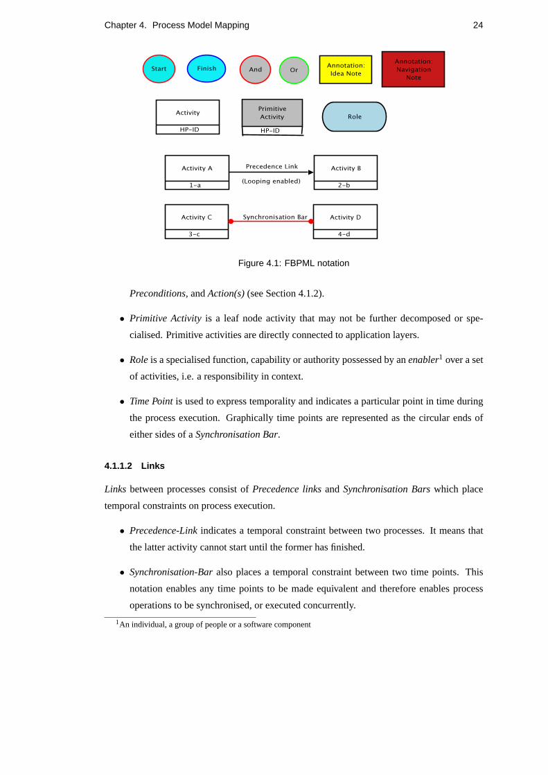
in FBPML is made up ofMain Nodes, Junctions, LinksandAnnotations. Figure 4.1 illustrates
the graphical notation for the main constructs of FBPML.
4.1.1.1 Nodes
The main Nodes are summarised as follows:
• Activity is the main concept to denote a process which may be further decomposed or
specialised into subprocesses. The three main components of an activity areTrigger(s),
23
Chapter 4. Process Model Mapping 24
Figure 4.1: FBPML notation
Preconditions,andAction(s)(see Section 4.1.2).
• Primitive Activity is a leaf node activity that may not be further decomposed or spe-
cialised. Primitive activities are directly connected to application layers.
• Roleis a specialised function, capability or authority possessed by anenabler1 over a set
of activities, i.e. a responsibility in context.
• Time Pointis used to express temporality and indicates a particular point in time during
the process execution. Graphically time points are represented as the circular ends of
either sides of aSynchronisation Bar.
4.1.1.2 Links
Links between processes consist ofPrecedence linksandSynchronisation Barswhich place
temporal constraints on process execution.
• Precedence-Linkindicates a temporal constraint between two processes. It means that
the latter activity cannot start until the former has finished.
• Synchronisation-Baralso places a temporal constraint between two time points. This
notation enables any time points to be made equivalent and therefore enables process
operations to be synchronised, or executed concurrently.
1An individual, a group of people or a software component
Chapter 4. Process Model Mapping 25
4.1.1.3 Junctions
Junctionsare used to connect multiple activities. They also define the temporal constraints and
control the initiation and finishing of parallel processes. The four types ofJunctionsin FBPML
areStart, Finish, AndandOr. Each use of a junction is a type of one-to-many (split junction)
or many-to-one (joint junction) relationships. The two most commonly used junctions in the
split and joint contexts areAndandOr. A subset of theOr construct is theXor, which imposes
that only one process is selected for execution. Their semantics are equivalent to the logical
operators ’and’ (∧), ’or’ (∨) and ’exclusive or’ (not-biconditional).
• And-Jointor Or-Joint indicates that there is more than one process preceding theAndor
Or junction but there is only one process following the junction. Section 4.3.2.2 provides
an example of the process diagram and formal description for theAnd-Jointconstruct.
• And-Splitor Or-Splitmeans that only one process will proceed to theAndor Or junction,
but more than one process will follow the junction. Section 4.3.2.3 provides an example
of the process diagram and formal description for theAnd-Splitconstruct.
• Startandfinishdenote the commencement and completion of a process model execution.
• Combinations ofAnd-And, And-Or, Or-AndandOr-Or constructs are also used to rep-
resent more complicated models. Section 4.3.5.1 illustrates an example that contains the
And-Andconstruct.
4.1.1.4 Annotations
AnnotationsincludeIdea NoteandNavigation Note. Neither of them contribute to the formal
semantics of the process model. Instead, they are used to help users to understand the processes
more clearly from an intuitive point of view.
• Idea Noterecords information which is related to the processes but not part of the process
model.
• Navigation Noterecords the relationships between diagrams in a model.
4.1.1.5 Action/Process Decomposition
• Task decomposition allows a process described at a higher level of abstraction to be de-
composed into more detailed sub-processes that are more explicit for its implementation
procedures.
• Alternative decomposition defines alternative ways of decomposing a higher level pro-
cess into different sets of subtasks; where only one set of those sub-tasks needs to be
finished to finish the higher level process (Chen-Burger and Lin, 2005).

Chapter 4. Process Model Mapping 26
4.1.2 Additional Primitives
Apart from the primitives described above, FBPML also provides some additional primitives
such as time and its manipulation;Trigger is one related construct. This is because it possesses
full first-order logic expressiveness, thus temporal behaviour could be expressed adequately.
It also describes conditions and rules very well;Preconditions, Postconditionsare used in
conjunction with conditional statements that are equivalent toif-then-elseconstructs in con-
ventional programming terms. FBPML also describes event and process life status and cycles.
Each node (or process) in FBPML has its attributes, such asProcess: InstanceId, Processtype,
Life status, Priority, Averagetime cost, Begin/Endtime, ServiceRequester/ServiceProvider,
Trigger, Preconditions, Actions, Postconditions.
4.1.3 FBPML Formal Definition
While the FBPML graphical representation provides intuitive reasoning, the FBPML formal
definition allows for machine processability. The following definition has been extracted from
(Chen-Burger et al., 2002), (Kuo et al., 2004) and (Kartsouni-Fourli, 2004)2.
4.1.3.1 Main Nodes
activity(ID, Name, Trigger, Precondition, Postcondition, Action, Description).
primitive activity(ID, Name, Trigger, Precondition, Postcondition, Action, Description).
4.1.3.2 Action
action(ActionType, Class, Instance).
4.1.3.3 Junctions
start(ActivityName).
junction(JunctionType, PreActivities, PostActivities).
4.1.3.4 Precedence Link
link(PrecedingActivity, ProceedingActivity).
4.2 OWL-S Process components
The basic properties that describe an OWL-S process are Input, Output, Precondition and Ef-
fects. OWL-S is made up of four main ontologies or classes;Service, Service Profile,
2The initial definition foractivity/6 andprimitive activity/6 have been extended toactivity/7 andprimitive activity/7by the inclusion ofDescription.

Chapter 4. Process Model Mapping 27
Service Model andGrounding. For the purpose of the process model mapping, we focus
our attention to a subclass ofService Model, the classProcess, which most appropriately
defines the execution of a process. Most of the following information is an extraction from the
Figure 4.2: The OWL-S Process Model ontology (OWL-S 2004).
specification of the latest OWL-S release (version 1.1)3.
4.2.1 Process
The classProcess draws upon well-established work in a variety of fields, including work in
AI on standardisations of planning languages, work in programming languages and distributed
systems, emerging standards in process modelling and workflow technology such as Process
Specification Language (PSL) and the Workflow Management Coalition effort (WfMC, 1995),
work on verb semantics and event structure, previous work on action-inspired Web service
markup, work in AI on modelling complex actions and work in agent communication lan-
guages.
Figure 4.2 provides a graphical view of the Process ontology. Note that not all the possible
constructs, classes, object properties and datatype properties pertaining to theProcess class
are shown. For instance, the classesResultVar (sublcass ofParameter) andEffect (defined
in Expression) are missing. The sublass relationship between the classPerform (invocations
3http://www.daml.org/services/owl-s/1.1/

Chapter 4. Process Model Mapping 28
of Atomic Processes) is also not shown. This is possibly due to the fact that OWL-S is still
under development and is constantly undergoing changes.
However, most of the main classes and relations that contribute to the execution of a
process are included. Subclasses ofProcess areAtomic Process, Simple Process and
Composite Process, described in the next three subsections.
4.2.1.1 Atomic Process
Atomic processes are directly invocable (by passing them the appropriate messages). Atomic
processes have no subprocesses and execute in a single step. That is, they take an input mes-
sage, process it, and then return their output message. For each atomic process, there must be
provided a grounding that enables a service requester to construct messages to the process from
its inputs and deconstruct replies.
4.2.1.2 Simple Process
Simple processes are not invocable and are not associated with a grounding, but, like atomic
processes, they are conceived of as having single-step executions. Simple processes are used as
elements of abstracton; a simple process may be used either to provide a view of (a specialised
way of using) some atomic process, or a simplified representation of some composite process
(for purposes of planning and reasoning). In the former case, the simple process isrealizedBy
the atomic process; in the latter case, the simple processexpandsTo the composite process.
Simple processes provide an abstraction mechanism to provide multiple views of the same
process.
4.2.1.3 Composite Process
Composite processes are decomposable into other (non-composite or composite) processes;
their decomposition can be specified by using control constructs such asSequence andIf-
Then-Else. A composite process is not a behaviour a service will do, but a behavior (or set
of behaviors) the client can perform by sending and receiving a series of messages. If the
composite process has an overall effect, then the client must perform the entire process in or-
der to achieve that effect. A precise specification of what it means to perform a process has
not yet been given, but it applies that if a composite is aSequence, then the client sends a
series of messages that invoke every step in order. One crucial feature of a composite pro-
cess is its specification of how its inputs are accepted by particular subprocesses, and how its
various outputs are produced by particular subprocesses. ACompositeProcess must have
a composedOf property by which is indicated the control structure of the composite, using a

Chapter 4. Process Model Mapping 29
ControlConstruct (see Section 4.2.4).
4.2.2 Parameter
Parameter stores inputs, outputs and results. It is a subclass of the Semantic Web Rule Lan-
guage’sswrl:Variable construct with a type description (an XML literal) and an optional
value expression, whereby the value of a constant parameter could be stored, for instance.
Input, Output, Local andResultVar are subclasses of Parameter. Local Parameters may
only be used with Atomic Processes. Their function is to identify variables whose scope is the
process as a whole, so that when they are bound in preconditions, they can be referenced in
outputs and effects.
Outputs are process parameters that are associated with descriptions byOutputBindings (see
Section 4.2.5) associated with particular result conditions.
4.2.3 Result
Result has zero or moreinCondition properties,withOutput properties,hasResultVar
properties andhasEffect properties. A diagrammatic representation of these properties are as
below:
Figure 4.3: The properties of the Result class.
4.2.4 Control Constructs
Control constructs govern the flow of execution of a process. Control constructs make up a
composite process - each composite process iscomposedOf control constructs, thus they play
an important role in characterising an OWL-S web service. The following are descriptions of
the major control constructs in OWL-S.
4.2.4.1 Sequence
A sequence is a list of control constructs to be done in order. Generally, process models that
are composed of a series of subprocesses are enclosed within a sequence construct in OWL-S.

Chapter 4. Process Model Mapping 30
4.2.4.2 Split
The components of aSplit process are a bag of process components to be executed concur-
rently. Split completes as soon as all of its component processes have been scheduled for
execution, which means that all processes within theSplit construct bag muststart for this
control construct to terminate successfully.
4.2.4.3 Split-Join
This control construct is used when a process consists of concurrent execution of a bunch
of process components with barrier synchronisation.Split-Join completes when all of its
components processes havecompleted. Note that this control construct complements theSplit
control construct. When used together,Split andSplit-Join can be used to define processes
that are partially synchronised.
4.2.4.4 Choice
This calls for the execution of a single control construct from a given bag of control constructs.
Any one of the given control constructs can be chosen for execution. Note that this is similar
to the Split control construct except that it imposes that onlyone process is selected for
execution over a bag of processes.
4.2.4.5 Any-Order
This control construct allows the process components (specified as a bag) to be executed in
some unspecified order but not concurrently. All components are required to execute and com-
plete. The execution of processes in anAny-Order construct cannot overlap, i.e. atomic pro-
cesses cannot be executed concurrently and composite processes cannot be interleaved. All
components must be executed, and as withSplit-Join, completion of all components is re-
quired.
4.2.4.6 If-Then-Else
This class has propertiesifCondition, then andelse holding different aspects of theIf-Then-Else.
Its semantics is intended to correspond to theIf, Then, Else constructs in conventional pro-
gramming language terms.
4.2.4.7 Iterate
This construct does require the number of iterations to be specified; the initiation, termination
or maintenance could be specified with thewhileCondition or anuntilCondition. It is an

Chapter 4. Process Model Mapping 31
abstractclass in the sense that it is not detailed enough to be instantiated in a process model. It
is defined to serve as the common superclass ofRepeat-While, Repeat-Until and potentially
other specific control constructs that might be needed in the future.
4.2.4.8 Repeat-While and Repeat-Until
These control constructs iterate until a condition becomes false or true, as in most programming
language conventions. Thus,Repeat-While may never act, whereasRepeat-Until always
acts at least once.
4.2.5 Bindings (DataFlow specifications)
Bindings are used to specify how output parameters are specified in different result conditions
for Atomic Processes, and they are used to specify how input parameters acquire values when
invoked by Perform’s in composite process descriptions. In each case, a binding takes a refer-
ence to a parameter being ’set’ - the#toParam, and one of several ways of describing a value.
However, with relation to the conceptual mapping task of this project, this construct is not
applicable, and will not be further investigated.
4.2.6 Expression
Expression contains ontology elements for capturing conditions and effects, it is the super-
class ofCondition andEffect. Conditions, (preconditions in FBPML terms), is defined as a
class of logical expressions, whose truth value can be determined for further action, for instance
it could be used with theIf-Then-Else control construct. Expressions can be in any allowed
logical language, and use parameters (primarily input and local) variables. Logical expressions
for preconditions, effects and result conditions are represented in a logical formalism, such as
Semantic Web Rule Language (SWRL), Declarative RDF System (DRS)(McDermott, 2004) or
Knowledge Interchange Format (KIF) (KIF, 1998) that are ’quoted’ by their encapsulation as
XMLLiterals. Among the three formalisms, SWRL has been the choice of extension for OWL
as it is the only one with well formed semantics .
Process.hasPrecondition andResult.inCondition properties refer to conditions that
are tested in specific contexts. Preconditions are evaluated with respect to the client environ-
ment before the process is invoked, result conditions are effectively meant to be ’evaluated’ in
the server context after the process has executed.

Chapter 4. Process Model Mapping 32
4.3 Mapping FBPML PL with OWL-S
4.3.1 Mapping of primitives
Primitive FBPML OWL-S Remarks
Main Nodes Activity Composite Process
Primitive Activity Atomic Process
Role Participant Only partial mapping. See Note 1.
Time Point No Mapping Limited notion of time in OWL-S.
See Note 2.
Links Precedence Links (part of)Sequence See Note 3.
Synchronisation Bar No Mapping
Junctions Start No Mapping Implied inSequence construct.
Finish No Mapping Implied inSequence construct.
And-Joint Split-Join See Note 4.
Or-Joint No mapping
And-Split Split
Or-Split Repeat-While, Only partial mapping. See Note 5.
Repeat-Until
Xor-Junction Choice See Note 6.
Annotations Idea Note No Mapping Does not contribute to process execution.
Navigation Note No Mapping Used for browsing purposes. Does not
contribute to the execution of a process.
Process Precondition Precondition Only partial mapping. See Note 7.
Components Trigger No mapping See Note 7.
Postcondition Effect Only partial mapping. See Note 8.
Precondition,
Trigger and Input/Output See Note 9.
Postcondition
Action Atomic Process Only partial mapping. See Note 10.
Conditional Action If-Then-Else
Table 4.1: Summary of mapping between FBPML and OWL-S primitives
Chapter 4. Process Model Mapping 33
4.3.1.1 Notes
1. In FBPML, aRole (adapted from RAD), is a responsibility in context; usually in the form
of aProvideror aRequester. In OWL-S theParticipant instances includeTheClient
and TheServer. Thus theRequesterrole corresponds toTheClient in OWL-S and
theProviderrole corresponds toTheServer OWL-S. FBPML’s notion ofRole is much
richer and could refer to an individual, a group of people or software components or a
combination of the above (Chen-Burger et al., 2002).
2. The time ontology (version 1.0) is used currently in very limited ways in the process
specification in OWL-S (described intime-entry.owl4).
3. Although there is no construct that maps to FBPML’sPrecedence Link, OWL-S denotes
the order of execution of processes within a sequence enclosed by<objList:first>...
</objList:first> and<objList:rest>...</objList:rest>. Appendix A2 pro-
vides a general syntax for an OWLSequence process.
4. TheAnd-Split is slightly modified to correspond to the OWL-SSplit construct where
the processes that branch into the junctions are synchronised. See Section 4.3.2.3.
5. Apart from theChoice construct which selects one process for execution, OWL-S does
not provide a direct equivalent for theOR construct. One usage of theOR construct can
be seen in the use of loops, which corresponds to theRepeat-While or Repeat-Until
construct in OWL-S.
6. Apart fromAnd andOr that describe the main junctions of a FBPML process model, a
less used construct is the Xor junction which indicates thatexactly oneout of a collection
of activites is selected for execution. This is described by theChoice control construct in
OWL-S. The Xor junction is subsumed by the Or junction and has been utilised by more
recent applications to make it more explicit for automation when bridging to (semantic
web or web service) methods that do not have Or junctions (Chen-Burger and Lin, 2005).
7. Since OWL-S does not support the notion of trigger, the combination ofPrecondition
andTrigger in FBPML approximately map toPrecondition in OWL-S.
8. Postcondition in FBPML describes the effectsand conditions which must hold true
after the execution of a process.
9. Input and output are not explicitly defined in FBPML, they are extracted from Precon-
dition, Trigger and Postcondition. Having explicit definitions for input and output could
be a placeholder for future work in FBPML PL.
4Seehttp://www.isi.edu/ pan/damltime/time-entry.owl
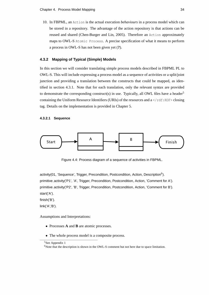
Chapter 4. Process Model Mapping 34
10. In FBPML, anAction is the actual executionbehavioursin a process model which can
be stored in a repository. The advantage of the action repository is that actions can be
reused and shared (Chen-Burger and Lin, 2005). Therefore anAction approximately
maps to OWL-SAtomic Process. A precise specification of what it means to perform
a process in OWL-S has not been given yet (?).
4.3.2 Mapping of Typical (Simple) Models
In this section we will consider translating simple process models described in FBPML PL to
OWL-S. This will include expressing a process model as a sequence of activities or a split/joint
junction and providing a translation between the constructs that could be mapped, as iden-
tified in section 4.3.1. Note that for each translation, only the relevant syntax are provided
to demonstrate the corresponding construct(s) in use. Typically, all OWL files have a header5
containing the Uniform Resource Identifiers (URIs) of the resources and a</rdf:RDF> closing
tag. Details on the implementation is provided in Chapter 5.
4.3.2.1 Sequence
Figure 4.4: Process diagram of a sequence of activities in FBPML.
activity(01, ’Sequence’, Trigger, Precondition, Postcondition, Action, Description6).
primitive activity(’P1’, ’A’, Trigger, Precondition, Postcondition, Action, ’Comment for A’).
primitive activity(’P2’, ’B’, Trigger, Precondition, Postcondition, Action, ’Comment for B’).
start(’A’).
finish(’B’).
link(’A’,’B’).
Assumptions and Interpretations:
• ProcessesA andB are atomic processes.
• The whole process model is a composite process.
5See Appendix 16Note that the description is shown in the OWL-S comment but not here due to space limitation.
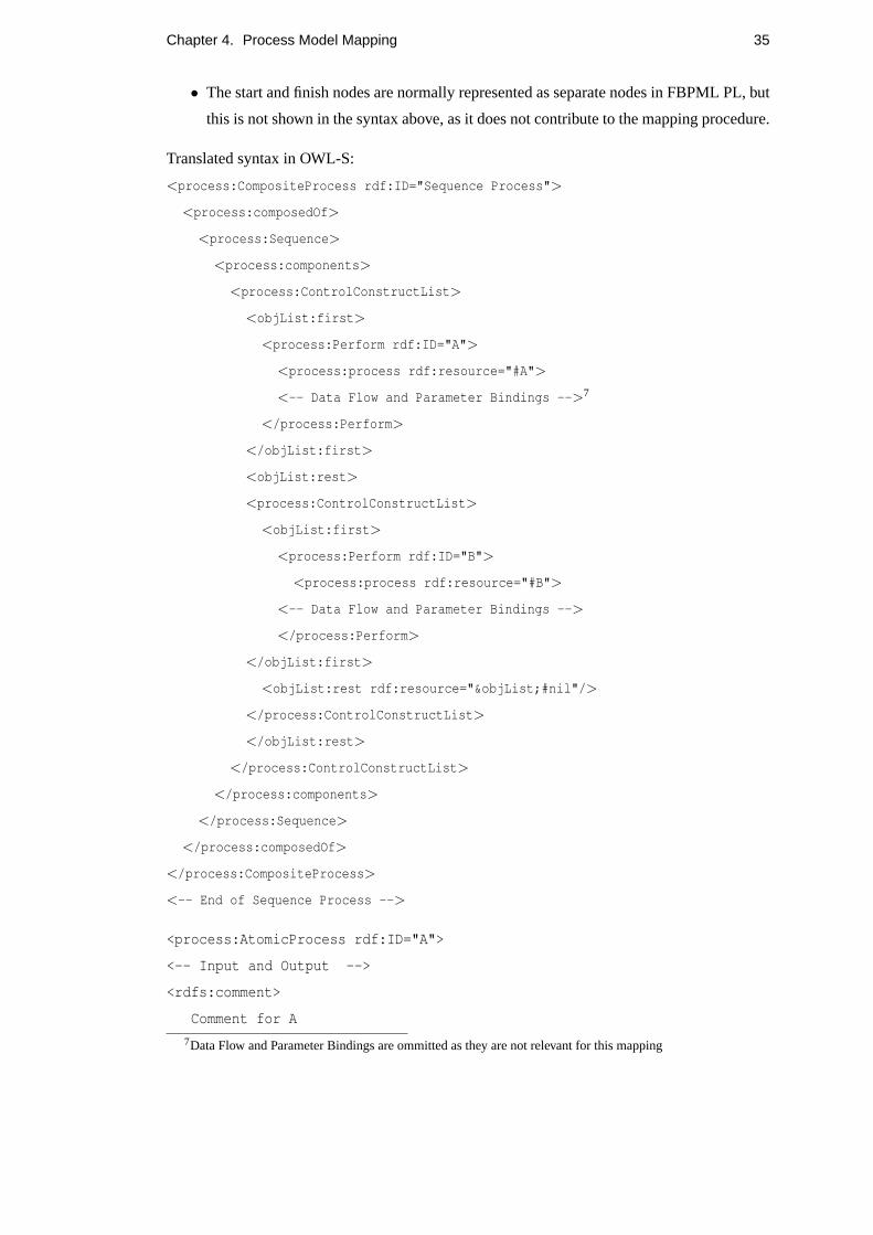
Chapter 4. Process Model Mapping 35
• The start and finish nodes are normally represented as separate nodes in FBPML PL, but
this is not shown in the syntax above, as it does not contribute to the mapping procedure.
Translated syntax in OWL-S:
<process:CompositeProcess rdf:ID="Sequence Process">
<process:composedOf>
<process:Sequence>
<process:components>
<process:ControlConstructList>
<objList:first>
<process:Perform rdf:ID="A">
<process:process rdf:resource="#A">
<-- Data Flow and Parameter Bindings -->7
</process:Perform>
</objList:first>
<objList:rest>
<process:ControlConstructList>
<objList:first>
<process:Perform rdf:ID="B">
<process:process rdf:resource="#B">
<-- Data Flow and Parameter Bindings -->
</process:Perform>
</objList:first>
<objList:rest rdf:resource="&objList;#nil"/>
</process:ControlConstructList>
</objList:rest>
</process:ControlConstructList>
</process:components>
</process:Sequence>
</process:composedOf>
</process:CompositeProcess>
<-- End of Sequence Process -->
<process:AtomicProcess rdf:ID="A">
<-- Input and Output -->
<rdfs:comment>
Comment for A
7Data Flow and Parameter Bindings are ommitted as they are not relevant for this mapping
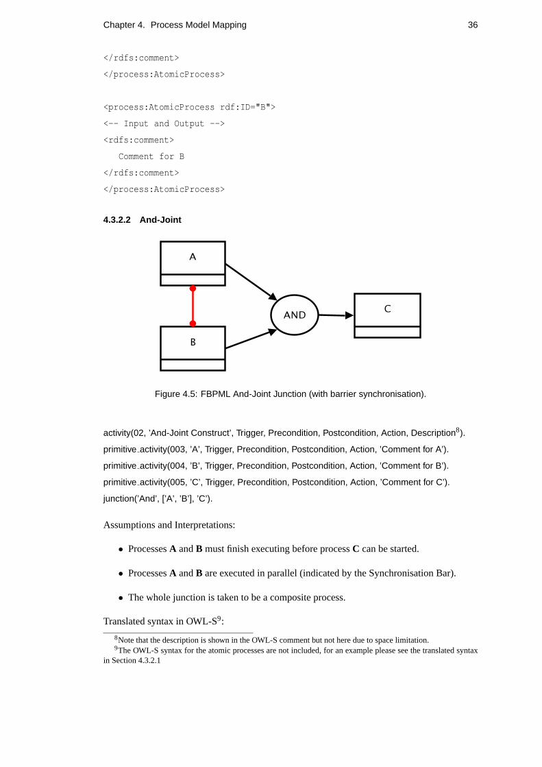
Chapter 4. Process Model Mapping 36
</rdfs:comment>
</process:AtomicProcess>
<process:AtomicProcess rdf:ID="B">
<-- Input and Output -->
<rdfs:comment>
Comment for B
</rdfs:comment>
</process:AtomicProcess>
4.3.2.2 And-Joint
Figure 4.5: FBPML And-Joint Junction (with barrier synchronisation).
activity(02, ’And-Joint Construct’, Trigger, Precondition, Postcondition, Action, Description8).
primitive activity(003, ’A’, Trigger, Precondition, Postcondition, Action, ’Comment for A’).
primitive activity(004, ’B’, Trigger, Precondition, Postcondition, Action, ’Comment for B’).
primitive activity(005, ’C’, Trigger, Precondition, Postcondition, Action, ’Comment for C’).
junction(’And’, [’A’, ’B’], ’C’).
Assumptions and Interpretations:
• ProcessesA andB must finish executing before processC can be started.
• ProcessesA andB are executed in parallel (indicated by the Synchronisation Bar).
• The whole junction is taken to be a composite process.
Translated syntax in OWL-S9:
8Note that the description is shown in the OWL-S comment but not here due to space limitation.9The OWL-S syntax for the atomic processes are not included, for an example please see the translated syntax
in Section 4.3.2.1

Chapter 4. Process Model Mapping 37
<process:CompositeProcess rdf:ID="AND-Joint Construct">
<process:composedOf>
<-- Input and Output -->
<rdfs:comment>
This AND-Joint Construct is a composite process made up of the conjunction
of processes B and C and the Atomic Process A.
</rdfs:comment>
<process:Sequence>
<process:components>
<process:ControlConstructList>
<objList:first>
<process:Perform rdf:ID="And-Joint Process">
<process:process rdf:resource="#And-Joint Process">
<-- Data flow and Parameter bindings -->
</process:Perform>
</objList:first>
<objList:rest>
<process:ControlConstructList>
<objList:first>
<process:Perform rdf:ID="C">
<process:process rdf:resource="#C">
<-- Data flow and Parameter bindings -->
</process:Perform>
</objList:first>
<objList:rest rdf:resource="&objList;#nil"/>
</process:ControlConstructList>
</objList:rest>
</process:ControlConstructList>
</process:components>
</process:Sequence>
</process:composedOf>
</process:CompositeProcess>
<-- End of And-Joint Construct -->
<process:CompositeProcess rdf:ID="And-Joint Process">
<process:composedOf>
<process:Split-Join>

Chapter 4. Process Model Mapping 38
<process:components>
<process:ControlConstructBag>
<objList:first>
<process:Perform rdf:ID="A">
<process:process rdf:resource="#A">
<-- Data flow and Parameter bindings -->
</process:Perform>
</objList:first>
<objList:rest>
<process:ControlConstructBag>
<objList:first>
<process:Perform rdf:ID="B">
<process:process rdf:resource="#B">
<-- Data flow and Parameter bindings -->
</process:Perform>
</objList:first>
<objList:rest rdf:resource="&objList;#nil"/>
</process:ControlConstructBag>
</objList:rest>
</process:ControlConstructBag>
</process:components>
</process:Split-Join>
</process:composedOf>
</process:CompositeProcess>
<-- End of AND-Joint Process -->
This junction is equivalent to the OWL-SSplit-Join construct, a similar representation of
the use of theSplit-Join construct is provided by the And-And Junction (Section 4.3.4.1).
4.3.2.3 And-Split
activity(04, ’And-Split Construct’, Trigger, Precondition, Postcondition, Action, Description10).
primitive activity(001, ’A’, Trigger, Precondition, Postcondition, Action, ’Comment for A’).
primitive activity(002, ’B’, Trigger, Precondition, Postcondition, Action, ’Comment for B’).
primitive activity(003, ’C’, Trigger, Precondition, Postcondition, Action, ’Comment for C’).
junction(’And’, ’A’, [’B’, ’C’]).
Assumptions and Interpretations:
10Note that the description is shown in the OWL-S comment but not here due to space limitation.

Chapter 4. Process Model Mapping 39
Figure 4.6: FBPML And-Split Junction (with barrier synchronisation).
• ProcessA must finish executing before processesB andC can be started.
• ProcessesB andC are executed in parallel (indicated by the Synchronisation Bar).
• The whole junction is taken to be a composite process.
Translated syntax in OWL-S:
<process:CompositeProcess rdf:ID="And-Split Construct">
<process:composedOf>
<-- Input and Output -->
<rdfs:comment>
This AND_Split Construct is a composite process made up of an Atomic
Process A, followed by the conjunction of atomic processes B and C.
</rdfs:comment>
<process:Sequence>
<process:components>
<process:ControlConstructList>
<objList:first>
<process:Perform rdf:ID="A">
<process:process rdf:resource="#A">
<-- Data flow and Parameter bindings -->
</process:Perform>
</objList:first>
<objList:rest>
<process:ControlConstructList>
<objList:first>
<process:Perform rdf:ID="And-Split Process">
<process:process rdf:resource="#And-Split Process">

Chapter 4. Process Model Mapping 40
<-- Data flow and Parameter bindings -->
</process:Perform>
</objList:first>
<objList:rest rdf:resource="&objList;#nil"/>
</process:ControlConstructList>
</objList:rest>
</process:ControlConstructList>
</process:components>
</process:Sequence>
</process:composedOf>
</process:CompositeProcess>
<-- End of And-Split Construct -->
<process:CompositeProcess rdf:ID="And-Split Process">
<process:composedOf>
<process:Split>
<process:components>
<process:ControlConstructBag>
<objList:first>
<process:Perform rdf:ID="B">
<process:process rdf:resource="#B">
<-- Data flow and Parameter bindings -->
</process:Perform>
</objList:first>
<objList:rest>
<process:ControlConstructBag>
<objList:first>
<process:Perform rdf:ID="C">
<process:process rdf:resource="#C">
<-- Data flow and Parameter bindings -->
</process:Perform>
</objList:first>
<objList:rest rdf:resource="&objList;#nil"/>
</process:ControlConstructBag>
</objList:rest>
</process:ControlConstructBag>
</process:components>

Chapter 4. Process Model Mapping 41
</process:Split>
</process:composedOf>
</process:CompositeProcess>
<-- End of AND_SplitProcess -->
This junction is approximately equivalent to theSplit construct in OWL-S.
4.3.2.4 Xor-Split
Figure 4.7: FBPML Xor-Split Junction.
activity(06, ’Xor-Split Construct’, Trigger, Precondition, Postcondition, Action, Description11).
primitive activity(001, ’A’, Trigger, Precondition, Postcondition, Action, ’Comment for A’).
primitive activity(002, ’B’, Trigger, Precondition, Postcondition, Action, ’Comment for B’).
primitive activity(003, ’C’, Trigger, Precondition, Postcondition, Action, ’Comment for C’).
junction(’Xor’, ’A’, [’B’, ’C’]).
Assumptions and Interpretations:
• ProcessA must finish executing before processesB or C can start.
• The whole junction is taken to be a composite process.
• Exactly one of the processesB or C will be triggered and executed properly, after the
preceding processA is finished.
Translated syntax in OWL-S:
<process:CompositeProcess rdf:ID="Xor-Split Construct">
<process:composedOf>
<-- Input and Output -->
<rdfs:comment>
11Note that the description is shown in the OWL-S comment but not here due to space limitation.

Chapter 4. Process Model Mapping 42
This Xor-Split Construct is a composite process made up of an Atomic
Process A, followed by either ONE of atomic processes B and C.
</rdfs:comment>
<process:Sequence>
<process:components>
<process:ControlConstructList>
<objList:first>
<process:Perform rdf:ID="A">
<process:process rdf:resource="#A">
<-- Data flow and Parameter bindings -->
</process:Perform>
</objList:first>
<objList:rest>
<process:ControlConstructList>
<objList:first>
<process:Perform rdf:ID="Xor-Split Process">
<process:process rdf:resource="#Xor-Split Process">
<-- Data flow and Parameter bindings -->
</process:Perform>
</objList:first>
<objList:rest rdf:resource="&objList;#nil"/>
</process:ControlConstructList>
</objList:rest>
</process:ControlConstructList>
</process:components>
</process:Sequence>
</process:composedOf>
</process:CompositeProcess>
<-- End of XOR_Split_Construct -->
<process:CompositeProcess rdf:ID="Xor-Split Process">
<process:composedOf>
<process:Choice>
<process:components>
<process:ControlConstructBag>
<objList:first>
<process:Perform rdf:ID="B">
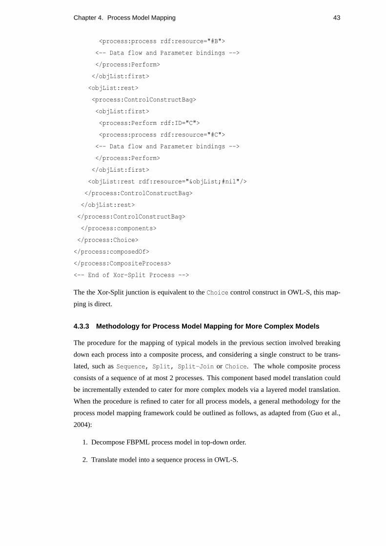
Chapter 4. Process Model Mapping 43
<process:process rdf:resource="#B">
<-- Data flow and Parameter bindings -->
</process:Perform>
</objList:first>
<objList:rest>
<process:ControlConstructBag>
<objList:first>
<process:Perform rdf:ID="C">
<process:process rdf:resource="#C">
<-- Data flow and Parameter bindings -->
</process:Perform>
</objList:first>
<objList:rest rdf:resource="&objList;#nil"/>
</process:ControlConstructBag>
</objList:rest>
</process:ControlConstructBag>
</process:components>
</process:Choice>
</process:composedOf>
</process:CompositeProcess>
<-- End of Xor-Split Process -->
The the Xor-Split junction is equivalent to theChoice control construct in OWL-S, this map-
ping is direct.
4.3.3 Methodology for Process Model Mapping for More Complex Models
The procedure for the mapping of typical models in the previous section involved breaking
down each process into a composite process, and considering a single construct to be trans-
lated, such asSequence, Split, Split-Join or Choice. The whole composite process
consists of a sequence of at most 2 processes. This component based model translation could
be incrementally extended to cater for more complex models via a layered model translation.
When the procedure is refined to cater for all process models, a general methodology for the
process model mapping framework could be outlined as follows, as adapted from (Guo et al.,
2004):
1. Decompose FBPML process model in top-down order.
2. Translate model into a sequence process in OWL-S.

Chapter 4. Process Model Mapping 44
3. All activities betweenstart andfinish nodes are composite components of the se-
quence process.
4. Exhaustively decompose each composite component into a sequence of its basic process
component, until as far as a simple process construct.
4.3.4 Examples of More Complex Models Mapping
More complex process models include the use of combinational branching junctions; the four
basic cases of these junctions are And-And, And-Or, Or-And and Or-Or. Since OWL does
not provide for the OR control construct, the only coupled junction that can be mapped is the
And-And and is illustrated below.
4.3.4.1 Example 1: Combinational And-And Junction
Figure 4.8: FBPML And-And Junction.
activity(06, ’And-And Junction’, Trigger, Precondition, Postcondition, Action, ’Desc’).
junction(’And’, ’A’, [’B’, ’C’, ’D’]).
junction(’And’, [’B’, ’C’, ’D’], ’E’).
primitive activity(001, ’A’, Trigger, Precondition, Postcondition, Action, ’Comment for A’).
primitive activity(002, ’B’, Trigger, Precondition, Postcondition, Action, ’Comment for B’).
primitive activity(003, ’C’, Trigger, Precondition, Postcondition, Action, ’Comment for C’).
primitive activity(004, ’D’, Trigger, Precondition, Postcondition, Action, ’Comment for D’).
primitive activity(005, ’E’, Trigger, Precondition, Postcondition, Action, ’Comment for E’).
The And-And Junction utilises the combination of the And-Split and And-Joint junctions as
shown in Figure 4.8. Following the methodology provided in Section 4.3.3, the process model
contained in this figure could be decomposed as follows:
Taking the And-And junction as an OWL-SSplit-Join, the order of execution is given by
the prefix notation:

Chapter 4. Process Model Mapping 45
Figure 4.9: Decomposition of FBPML process model containing the And-And Junction.
Sequence(A, Split-Join(B,C,D), E).
The translated syntax in OWL-S:
<process:CompositeProcess rdf:ID="And-And Process">
<process:composedOf>
<-- Input and Output -->
<rdfs:comment>
Desc
</rdfs:comment>
<process:Sequence>
<process:components>
<process:ControlConstructList>
<objList:first>
<process:Perform rdf:ID="A">
<process:process rdf:resource="#A">
<-- Data flow and Parameter bindings -->
</process:Perform>
</objList:first>
<objList:rest>
<process:ControlConstructList>
<objList:first>
<process:Perform rdf:ID="And-And Junction">
<process:process rdf:resource="#And-And Junction">
<-- Data flow and Parameter bindings -->
</process:Perform>
</objList:first>
<objList:rest>

Chapter 4. Process Model Mapping 46
<process:ControlConstructList>
<objList:first>
<process:Perform rdf:ID="E">
<process:process rdf:resource="#E">
<-- Data flow and Parameter bindings -->
</process:Perform>
</objList:first>
<objList:rest rdf:resource="&objList;#nil"/>
</process:ControlConstructList>
</objList:rest>
</process:ControlConstructList>
</objList:rest>
</process:ControlConstructList>
</process:components>
</process:Sequence>
</process:composedOf>
</process:CompositeProcess>
<-- End of And-And Process -->
<process:CompositeProcess rdf:ID="And-And Junction">
<process:composedOf>
<process:Split-Join>
<process:components>
<process:ControlConstructBag>
<objList:first>
<process:Perform rdf:ID="B">
<process:process rdf:resource="#B">
<-- Data flow and Parameter bindings -->
</process:Perform>
</objList:first>
<objList:rest>
<process:ControlConstructBag>
<objList:first>
<process:Perform rdf:ID="C">
<process:process rdf:resource="#C">
<-- Data flow and Parameter bindings -->
</process:Perform>
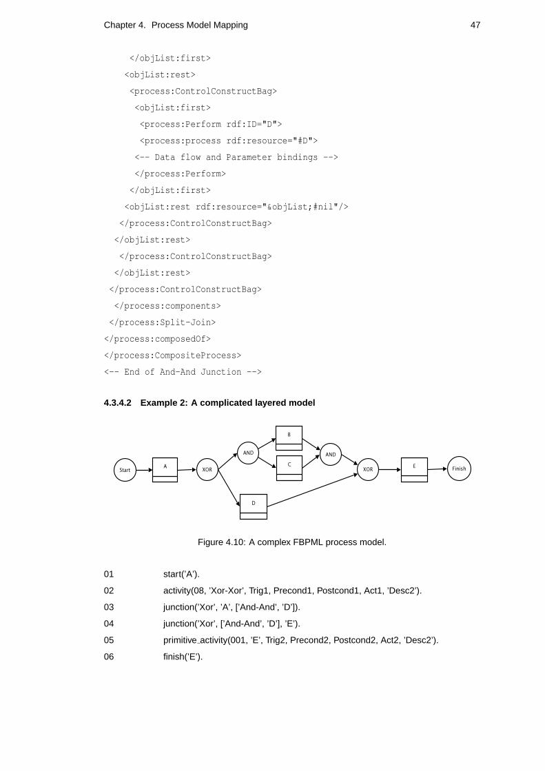
Chapter 4. Process Model Mapping 47
</objList:first>
<objList:rest>
<process:ControlConstructBag>
<objList:first>
<process:Perform rdf:ID="D">
<process:process rdf:resource="#D">
<-- Data flow and Parameter bindings -->
</process:Perform>
</objList:first>
<objList:rest rdf:resource="&objList;#nil"/>
</process:ControlConstructBag>
</objList:rest>
</process:ControlConstructBag>
</objList:rest>
</process:ControlConstructBag>
</process:components>
</process:Split-Join>
</process:composedOf>
</process:CompositeProcess>
<-- End of And-And Junction -->
4.3.4.2 Example 2: A complicated layered model
Figure 4.10: A complex FBPML process model.
01 start(’A’).
02 activity(08, ’Xor-Xor’, Trig1, Precond1, Postcond1, Act1, ’Desc2’).
03 junction(’Xor’, ’A’, [’And-And’, ’D’]).
04 junction(’Xor’, [’And-And’, ’D’], ’E’).
05 primitive activity(001, ’E’, Trig2, Precond2, Postcond2, Act2, ’Desc2’).
06 finish(’E’).

Chapter 4. Process Model Mapping 48
07 activity(09, ’And-And’, Trig3, Precond3, Postcond3, Act3, ’Desc3’).
08 junction(’And’, ’J1’, [’B’, ’C’]).
09 junction(’And’, [’B’, ’C’], ’J2’).
10 primitive activity(002, ’A’, Trig4, Precond4, Postcond4, Act4, ’Desc4’).
11 primitive activity(003, ’B’, Trig5, Precond5, Postcond5, Act5, ’Desc5’).
12 primitive activity(004, ’C’, Trig6, Precond6, Postcond6, Act6, ’Desc6’).
13 primitive activity(005, ’D’, Trig7, Precond7, Postcond7, Act7, ’Desc7’).
Assumptions and Interpretations:
• Ordering of junctions are from top-most (outer) to down-most (inner). For example the
Xor-Xor definition (lines 3-4) appears before theAnd-And definition (lines 8-9).
• The branches coming out and going into the Xor junctions are called ’J1’ and ’J2’ re-
spectively.
Following the methodology provided in Section 4.3.4, the process model could be decomposed
in the following manner:
Figure 4.11: Decomposition of the complex process model.
• The whole process is a composite process made up of aSequence consisting of an atomic
process A, a composite process containing both the outer most XOR junctions, called
XOR-XOR, and an atomic process, D.
• The Composite process XOR-XOR is aChoice process of either atomic process D or a
Split-Join of B and C (the AND-AND junction).
To improve readability, the order of execution in prefix notation is as follows:
Sequence(A, Xor(And(B, C), D), E)
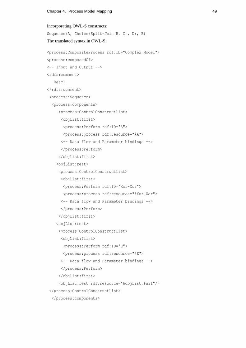
Chapter 4. Process Model Mapping 49
Incorporating OWL-S constructs:
Sequence(A, Choice(Split-Join(B, C), D), E)
The translated syntax in OWL-S:
<process:CompositeProcess rdf:ID="Complex Model">
<process:composedOf>
<-- Input and Output -->
<rdfs:comment>
Desc1
</rdfs:comment>
<process:Sequence>
<process:components>
<process:ControlConstructList>
<objList:first>
<process:Perform rdf:ID="A">
<process:process rdf:resource="#A">
<-- Data flow and Parameter bindings -->
</process:Perform>
</objList:first>
<objList:rest>
<process:ControlConstructList>
<objList:first>
<process:Perform rdf:ID="Xor-Xor">
<process:process rdf:resource="#Xor-Xor">
<-- Data flow and Parameter bindings -->
</process:Perform>
</objList:first>
<objList:rest>
<process:ControlConstructList>
<objList:first>
<process:Perform rdf:ID="E">
<process:process rdf:resource="#E">
<-- Data flow and Parameter bindings -->
</process:Perform>
</objList:first>
<objList:rest rdf:resource="&objList;#nil"/>
</process:ControlConstructList>
</process:components>

Chapter 4. Process Model Mapping 50
</process:Sequence>
</process:composedOf>
</process:CompositeProcess>
<-- End of Complex Model -->
<process:CompositeProcess rdf:ID="Xor-Xor">
<process:composedOf>
<process:Choice>
<process:components>
<process:ControlConstructBag>
<objList:first>
<process:Perform rdf:ID="And-And">
<process:process rdf:resource="#And-And">
<-- Data flow and Parameter bindings -->
</process:Perform>
</objList:first>
<objList:rest>
<process:ControlConstructBag>
<objList:first>
<process:Perform rdf:ID="D">
<process:process rdf:resource="#D">
<-- Data flow and Parameter bindings -->
</process:Perform>
</objList:first>
<objList:rest rdf:resource="&objList;#nil"/>
</process:ControlConstructBag>
</objList:rest>
</process:ControlConstructBag>
</process:components>
</process:Choice>
</process:composedOf>
</process:CompositeProcess>
<-- End of Xor-Xor -->
<process:CompositeProcess rdf:ID="And-And">
<process:composedOf>
<process:Split-Join>

Chapter 4. Process Model Mapping 51
<process:components>
<process:ControlConstructBag>
<objList:first>
<process:Perform rdf:ID="B">
<process:process rdf:resource="#B">
<-- Data flow and Parameter bindings -->
</process:Perform>
</objList:first>
<objList:rest>
<process:ControlConstructBag>
<objList:first>
<process:Perform rdf:ID="C">
<process:process rdf:resource="#C">
<-- Data flow and Parameter bindings -->
</process:Perform>
</objList:first>
<objList:rest rdf:resource="&objList;#nil"/>
</process:ControlConstructBag>
</objList:rest>
</process:ControlConstructBag>
</process:components>
</process:Split-Join>
</process:composedOf>
</process:CompositeProcess>
<-- End of And-And -->
4.4 Discussion
From the application of the conceptual mapping methodology on the process model compo-
nents, it can be seen that unlike the data model mapping, the process model mapping is less
straightforward and poses some difficulties and challenges. This is interesting as it brings forth
the capabilities and limitations of the two process model languages. It also highlights the dif-
ferences between FBPML and OWL-S that were not revealed by the data model mapping.
As of yet, OWL-S does not facilitate theOr control construct. It does, however, provide for
a subset ofOr, theXor, through theChoice control construct. One can simulateOr by using
a bunch ofXor statements but it wouldn’t be very practical. Thus the mapping of the FBPML

Chapter 4. Process Model Mapping 52
Or junctions was not performed.
The closest form of the use of theOr control construct within OWL-S can be traced in the
use of iterations or loops. A loop in FBPML is represented using an activity which is connected
to anOR-Split, and one of the branches from the split connects back to the same activity. The
mechanism in OWL-S to control loops is provided by the control constructIteration and its
subclassesRepeat-While andRepeat-Until.
Conditional actions are expressed using theIf-Then-Else control construct in OWL-S.
As stated previously, OWL does not provide full expressivity to describe rules and conditions,
hence SWRL is used as a logical formalism to extend the set of OWL DL axioms to include
Horn-like rules. However, SWRL is being extended towards first-order logic via SWRL FOL,
which is still under rapid development. It is unclear how the rule constructs will change over
time and built into OWL. Thus the mapping between FBPML’sConditionalactionand OWL-
S’s If-Then-Else was not performed. The mapping of iterations was also not performed for
the same reason; they involve the evaluation of conditions, which are expressed using SWRL
FOL.
In relation to their suitability for describing process model execution, FBPML PL is richer
as it has both visual and formal representations for its process model while OWL-S only con-
tains the latter. The FBPML Process Diagram is intuitive and promotes human reasoning;
OWL-S’s RDF-based tags, on the contrary, aims to provide improved machine-processability.
This clash is vital as it suggests that there may never be a complete mapping between the two
languages, nevertheless it would be fitting to allow for the newer and developing technology
to benefit from the more mature language by narrowing the gap between them as much as
possible.
Chapter 5
Implementation and Analysis
A system to automate the conceptual mapping provided in the preceding chapter was imple-
mented using a Prolog parser. We start by providing an architectural diagram for the overall
system, clearly separating the data schema from the process schema for both languages. We
then discuss the design rationale and criteria for the process model mapper which was built on
an incremental approach. Next, the predicates that constitute the main workings of the system
program are examined closer. The correctness of the translated models and an evaluation are
given in theTheoretical Analysissection. The mapping procedure, algorithm and difficulties
are discussed rigorously to conclude.
5.1 System Architecture
The overall system architecture is depicted in figure 5.1, which has been adapted from the
Knowledge Based Support Tool for Business Models (KBST-BM) modelling support.
As depicted by the figure, the data model and process model translation components are dis-
tinctly separate and thus could be developed independently. Adopting this approach, a process
model translator was developed independently. The reasons for focusing the implementation
on the process model mapping only are due to time limitation and the existence of an imple-
mentation of a data model mapping tool of FBPML DL to OWL, which is part of a different
project1, for a different domain. Furthermore, as pointed out in Section 4.4, the process model
mapping constitutes the most important aspect of the whole conceptual mapping framework.
1Advanced Knowledge Technologies (AKT) for Support Ontology, AIAI, University of Edinburgh and collabo-rators
53

Chapter 5. Implementation and Analysis 54
Figure 5.1: An architectural overview of FBPML to OWL-S Mapping Engine.
5.2 Process Model Translator
The process model translator was developed using SICStus2 Prolog 3.10.1 on (Red Hat) Linux
9, the design was based on parsing first-order logic (Horn) clauses into hierarchical OWL and
RDF tree-like tags. A general algorithm is provided in Section 4.3.3, based on process decom-
positioning. However, the implementation was based on more specific procedures which were
built up incrementally as the complexity of the process model increased. The main aim of the
process model translator was to cater for any general process model described in FBPML PL to
be converted to OWL syntax. As pointed out in Section 4.4, the process model mapping does
not encompass all the possible primitives and process constructs, and is thus limited. Hence
the system was implemented to perform the translation as closely, accurately and directly as
possible, taking into account some viable assumptions and interpretations.
The main program is contained within the fileprocess map.pl. The program loads a pre-
defined library,library.pl which contains functions commonly used by the main program
such as standard list processing routines, and a preprocessing fileutility.pl which trans-
forms FBPML data models to Prolog compatible syntax before they could be manipulated by
the main program.
2An implementation by Intelligent Systems Laboratory, Swedish Institute of Computer Science that conformsto the ISO Prolog standard.
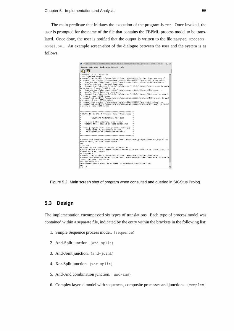
Chapter 5. Implementation and Analysis 55
The main predicate that initiates the execution of the program isrun. Once invoked, the
user is prompted for the name of the file that contains the FBPML process model to be trans-
lated. Once done, the user is notified that the output is written to the filemapped-process-
model.owl. An example screen-shot of the dialogue between the user and the system is as
follows:
Figure 5.2: Main screen shot of program when consulted and queried in SICStus Prolog.
5.3 Design
The implementation encompassed six types of translations. Each type of process model was
contained within a separate file, indicated by the entry within the brackets in the following list:
1. Simple Sequence process model.(sequence)
2. And-Split junction.(and-split)
3. And-Joint junction.(and-joint)
4. Xor-Split junction.(xor-split)
5. And-And combination junction.(and-and)
6. Complex layered model with sequences, composite processes and junctions.(complex)

Chapter 5. Implementation and Analysis 56
Each type of process model translation will be examined in turn.
5.3.1 Typical (Simple) Process Model Translator
5.3.1.1 Sequence
A simple sequence process consists of a series of activites bound by the ’start’ and ’finish’
nodes. The conceptual mapping and the representations in FBPML and OWL-S of this type
are provided in Section 4.3.3.1. The procedure involved identifying the start node, inserting it
as the first element of a sequence and adding subsequent connected nodes into the sequence
until the end node is encountered. This implementation is straightforward, as the processes are
enclosed within the OWL<Sequence> ... </Sequence> tag. This is the basic construc-
tion of all processes described by FBPML. See Appendix A.2 for a general concrete syntax for
describing sequences in OWL-S.
5.3.1.2 And-Joint
The And-Joint junction denotes that more than one process are flowing into the junction and
all processes must complete before the process proceeding the junction can start. The con-
ceptual mapping and the representations in FBPML and translated OWL-S syntax of this type
are provided in Section 4.3.3.2. The procedure is slightly more complicated in that it involved
breaking the whole process into a sequence of two processes, the first is the process containing
the two processes branching into the junction and the second is the process that follows the
junction. The first process is then further defined as composed of aSplit-Join with the ele-
ments being the two processes within it. Note that these two processes had to be synchronised
for this (FBPML And-Joint to OWL-S Split-Joint) mapping to be accurate. A general concrete
syntax is provided in Appendix 3.
5.3.1.3 And-Split
This junction is approximately the complement of the And-Joint junction. Following a similar
procedure as the one provided for the And-Joint; the first process within the sequence is taken
to be the process going into the junction and the second a composite process, which is then
defined as the composition of aSplit with the proceeses branching out of the junction as its
elements. Note that these two processes had to be synchronised for this (FBPML And-Split to
OWL-S Split) mapping to be accurate. Its general concrete syntax is similar toSplit-Join’s,
provided in Appendix A.3.

Chapter 5. Implementation and Analysis 57
5.3.1.4 Xor-Split
This junction is similar to the And-Split, except that it selects onlyoneprocess for execution.
Again, the process is decomposed into a sequence with two procceses; the first is the process
preceding the junction and the second being the composite process containing the two processes
branching out of the junction, enclosed within an OWL-SChoice. The general concrete syntax
is also similar toSplit-Join andSplit, given in Appendix A.3.
5.3.2 Complex Process Model Translator
5.3.2.1 And-And Junction
The And-And junction, as its name suggests, has two And junctions coupled to form a com-
binational junction. The example FBPML process diagram, syntax and OWL-S translation
are provided in Section 4.3.4.1. It can be seen as the combination of an And-Split and and
And-Joint. The procedure for translating this model is more complicated as it required the
program to identify the ’And-And’ construct given twojunction predicates. This is done by
checking for equality between the list of processes branching out of the And-Split junction and
those branching into the And-Split junction. Once the And-And junction is identified, it is then
added into a sequence with the process preceding the junction as the process previous to it and
the process proceeding the junction as the process following it. This junction corresponds to
the OWL-SSplit-Join. Once again, the processes within the junction are synchronised to
denote concurrency.
This may cause confusion as the And-Joint junction (Section 5.3.1.2) was also implemented
as the Split-Join. It should be noted that the translations of the simple models (apart from
the Sequence) were performed to demonstrate component or primitive mapping, rather than a
complete process model mapping. Therefore, while the And-Joint junction is a valid construct
within a FBPML process model, its use on its own as depicted by the example provided in
Section 4.3.3.2 is not practical. Usually it is coupled with the And-Split in the more practical
And-And junction, which translates to the OWL-SSplit-Join. Using a similar argument, the
Xor-Xor junction could be defined as aChoice.
5.3.2.2 Complex layered model
The component based translation procedures discussed so far could be extended incrementally
to cater for more complicated layered process models. This is given by the application of the
methodology given in Section 4.3.3. An example of a complicated process model is illustrated
in Section 4.3.4.2. The implementation has parsed the process as a sequence and decomposed
each distinct process component it has identified for each member of the sequence, (where a

Chapter 5. Implementation and Analysis 58
component can be any one of the five types discussed above). Each of these components, in
turn, if not atomic already, is decomposed into a sequence, and so on recursively, thus exhaus-
tive decompositioning. The workings of the main predicates are discussed in the next section.
The translation of the complex model mapping has been implemented successfully, al-
though it is limited to components of type sequences, atomic processes and junctions. A more
complete system would incorporate iterations (loops) and conditional statements (if-then-else),
which play important roles for process execution. However, it is currently not feasible to im-
plement these constructs, for reasons and justifications provided in Section 4.4.
5.3.3 Main Predicates
This section provides the main predicates in the programprocess map.pl. The top most pred-
icate which launches the program execution isrun. The algorithm that follows this predicate
consists of the following:
1. Read process model filename from user.
2. Open output file(mapped-process-model.owl) for writing.
3. Write OWL header (example in Appendix 1).
4. Write process header (for a Composite Process).
5. Write Input/Output and Comments.
6. Parse the process type (one of 5.3.1.1-5.3.1.4, 5.3.2.1) and perform specific translation.
7. Define atomic processes.
8. End the OWL file (enclose with</rdf:RDF> tag).
The specific translationin item 6 above refer to the procedures discussed in their respective
sections prior to this. General predicates which are commonly used by most process types
were defined withinprocess map.pl. Some of the most useful are listed below:
For sequences, their specific predicates and descriptions are as follows:
For junctions, the predicates mostly involve determining the type of junction (Split/Joint), and
list processing for dealing with elements in branches in and out of junctions.
For more complex models, involving the And-And junction for instance, a separate predicate
for junction manipulation was written because the nature of the junction is more complicated
than a simple (single) split or joint junction. However, it utilises some predicates from the sim-
ple junctions, such asdecompose junction/3 andclose junction/3. For more complex
models, the procedure is close to the simple sequence process decomposition, additionally it
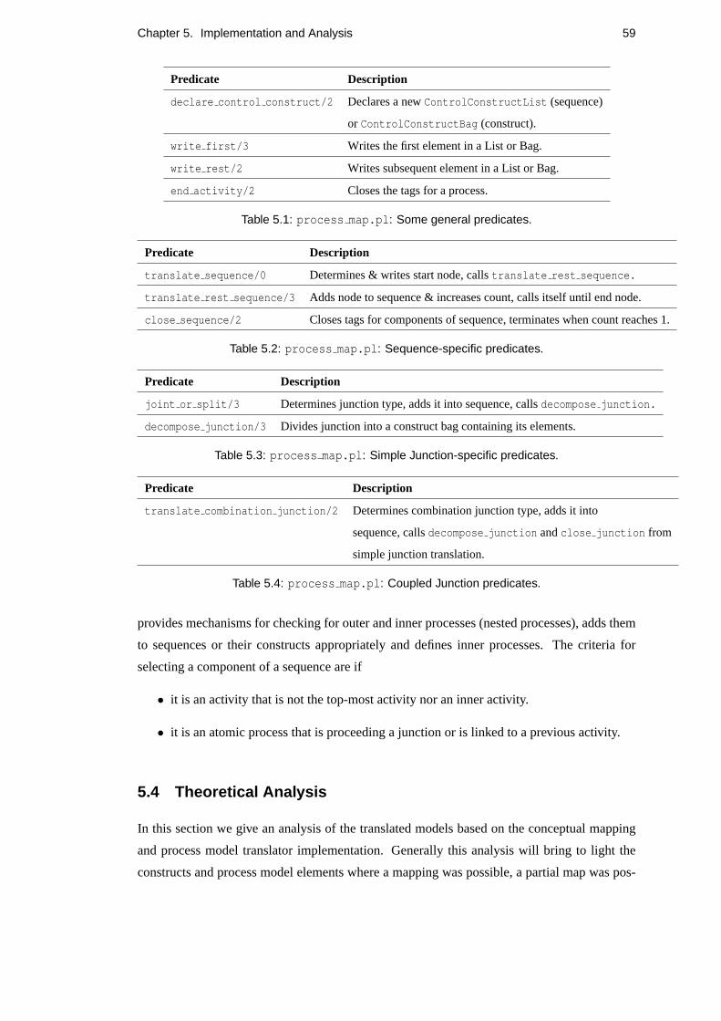
Chapter 5. Implementation and Analysis 59
Predicate Description
declare control construct/2 Declares a newControlConstructList (sequence)
or ControlConstructBag (construct).
write first/3 Writes the first element in a List or Bag.
write rest/2 Writes subsequent element in a List or Bag.
end activity/2 Closes the tags for a process.
Table 5.1: process map.pl: Some general predicates.
Predicate Description
translate sequence/0 Determines & writes start node, callstranslate rest sequence.
translate rest sequence/3 Adds node to sequence & increases count, calls itself until end node.
close sequence/2 Closes tags for components of sequence, terminates when count reaches 1.
Table 5.2: process map.pl: Sequence-specific predicates.
Predicate Description
joint or split/3 Determines junction type, adds it into sequence, callsdecompose junction.
decompose junction/3 Divides junction into a construct bag containing its elements.
Table 5.3: process map.pl: Simple Junction-specific predicates.
Predicate Description
translate combination junction/2 Determines combination junction type, adds it into
sequence, callsdecompose junction andclose junction from
simple junction translation.
Table 5.4: process map.pl: Coupled Junction predicates.
provides mechanisms for checking for outer and inner processes (nested processes), adds them
to sequences or their constructs appropriately and defines inner processes. The criteria for
selecting a component of a sequence are if
• it is an activity that is not the top-most activity nor an inner activity.
• it is an atomic process that is proceeding a junction or is linked to a previous activity.
5.4 Theoretical Analysis
In this section we give an analysis of the translated models based on the conceptual mapping
and process model translator implementation. Generally this analysis will bring to light the
constructs and process model elements where a mapping was possible, a partial map was pos-

Chapter 5. Implementation and Analysis 60
Predicate Description
translate complex model/2 Determines & writes start node, callstranslate rest complex.
translate rest complex/3 Looks for valid subactivities to be added into sequence.
inner process/2 Determines if a process with a coupled junction is contained within another.
define inner junctions/0 Looks for inner junctions and parses them according to their types.
Table 5.5: process map.pl: Complex model predicates.
sible or a mapping was not possible. Table 5.6 summarises the evaluation of the translated
constructs and process models.

Chapter 5. Implementation and Analysis 61
Category Component Correct Translation Mapping Category
Data Model Class Yes Direct
Components Instance Yes Direct
Class relations Partial Partial
Instance relations Yes Direct
Roles Partial Partial
Main Nodes Activity Yes Direct
Primitive Activity Yes Direct
Role Partial Partial
Time Point N/A N/A
Links Precedence Links Partial Partial
Synchronisation Bar No No
Junctions Start Yes No
Finish Yes No
And-Joint Partial Partial
And-Split Partial Partial
Or-Joint No No
Or-Split No No
Xor Yes Direct
And-And Yes Direct
Xor-Xor Yes Direct
Iteration N/A N/A
Annotations Idea Note N/A N/A
Navigation Note N/A N/A
Process Precondition Partial Partial
Components Trigger No No
Postcondition Partial Partial
Action Partial Partial
Conditional Action N/A N/A
Table 5.6: Analysis of mapping between FBPML and OWL-S data and process model compo-
nents.
N/A (Not Applicable) implies that the mapping was not attempted.
From the table of analysis, it can be observed that most of the date model components can be
mapped directly, while the process model components, in particular the junctions, could only
be partially mapped or not mapped at all. Those that were not applicable meant that there was
insufficient information to proceed (e.g. temporal constructs), incomplete or missing constructs
Chapter 5. Implementation and Analysis 62
(e.g.Or junction).
Discussions and justifications for issues relating to data model mapping are given in Section
3.4 while those specific to process model mapping are provided in Section 4.4. The analysis
suggests that the mapping between FBPML and OWL-S is both partial and incomplete. Partial
because there are some elements that exist in FBPML but not in OWL-S (e.g.Trigger, Or) and
incomplete because some of the mapping cannot be conducted due to lack of knowledge about
an element that is still in progress (e.g. rules cannot be mapped because the status of SWRL
FOL is still unclear).
The reason for this problem lies in the fact that OWL-S uses programming-like control
constructs as its basic building blocks, which is inadequate for all process execution modelling
(Guo et al., 2004). This problem is also a common problem for BPEL4WS (Section 2.2.1).
One workaround, as suggested byGuo et al. is by redrawing the FBPML model to allow it
to be decomposed to an OWL-S acceptable way without affecting its meaning. However, this
does not guarantee that the re-drawn model is equivalent to the original one, it also poses syn-
chronisation problems.
The implementation of the process model translator, although limited, decomposes the se-
quences and combination junctions in a methodical manner. The problem will arise if loops,
which may cause partly overlapped processes, are added to the process model. When this hap-
pens, the process model may not be decomposed, thus causing mapping problems.
Thus, we can conclude that the formal mapping between FBPML and OWL-S is very chal-
lenging and will require more insight and exploration before a reasonable mapping framework
could be formulated. The essence of the analysis is that a much thorough understanding for
both languages has been gained and this can work as the groundwork towards future directions.

Chapter 6
Conclusions and Future Work
In this work we have demonstrated a conceptual mapping framework between two formal lan-
guages, FBPML and OWL-S. The former is traditionally used in the context of business pro-
cess modelling and the latter in the domain of Semantic Web Services. We have also attempted
to automate the translation of the process modelling aspect between the two languages. The
conceptual mapping exercise and implementation have brought to light some vital differences
between the construction of the two languages which suggests that the mapping between them
is partial. Furthermore, the specification of some aspects of OWL-S are still in progress and,
hence, the mapping is not complete. By critically analysing and evaluating the translated pro-
cess models, we have identified several problems with the OWL-S process constructs. In this
chapter we conclude by pointing out the major issues pertaining to Business Process Technolo-
gies and Semantic Web Services. We also recommend a few directions for OWL-S to pursue,
along with future work that could be continued from here.
6.1 Continued Utilisation of Business Process Technologies
From the introduction and background provided on BPM methods, it can be seen that they
provide a mature way to describe organisational needs and process flow execution for business
establishments. One BPM language that has been examined in this work is FBPML. This lan-
guage is unique in that it has adapted and merged visual and formal capabilities from several
standard BPM languages to form a rich language that supports both human understandability
and machine processability. These features are important as they have significant implications
for emerging technologies such as Semantic Web Services that strife for versatility and uni-
versality from applications that provide them. In order to bridge the gap that exists between
BPM methods and Semantic Web Services, a conceptual mapping framework has been devised
and implemented in this work. Narrowing the gap between business process technologies and
Semantic Web Services has opened a window of opportunity for the more established BPM
63
Chapter 6. Conclusions and Future Work 64
methods to be utilised by the less mature and ever evolving Semantic Web technologies. It is
hoped that the growth of Semantic Web standards such as OWL-S could be strengthened and
enriched by manipulating more mature technologies such as BPM methods.
6.2 Recommendations for OWL-S
Based on the theoretical analysis of the conceptual mapping exercise, provided in Chapter 5,
it is clear that OWL-S still lacks some fundamental constructs that a viable language should
have. The most obvious shortcoming is it does not facilitate theOr control construct which
is essential for process execution. The status of the use of the logical formalism SWRL FOL
within OWL should also be made clearer and more explicit. It is hoped that other missing
constructs should also be assessed for suitability to be incorporated within OWL-S (e.gTrigger)
to provide for a richer formalism.
6.2.1 Provision for Or control construct
As of now, the mapping of FBPML’sOr to OWL-S could be made possible by making use of a
series ofXor constructs (which maps to OWL-S’sChoice), but this could get complicated and
is thus impractical. Therefore to better suit FBPML, OWL-S should incorporate theOr control
construct (see Section 4.4 for more explanation). This would also strenghten it structurally as
a process modelling and semantic web compatible language.
6.2.2 Complete formalism for rules and conditions
Secondly, we have highlighted the inadequacy of OWL as a language for expressing logical
rules and conditions (Section 2.4.1). As a result, it has been extended to include SWRL con-
structs, which also come in concrete syntax as SWRL tags embedded within OWL (Section
2.4.2). However, as SWRL is moving towards SWRL FOL, it is still unclear as to when this
new formalism will be ready for use. Providing expressivity close to first order logic would
be very beneficial on the long run, thus this step is of crucial importance to the development
of OWL-S. It is hoped that once SWRL FOL is complete, OWL-S will provide a more com-
plete formalism for expressing rules and conditions. The mapping for loops and conditional
statements from FBPML to OWL-S could also be performed.
6.2.3 Combining OWL-S with WSMO
After a thorough examination of OWL-S from the data and process modelling aspects, and its
current status as a leading semantic web service technology, it remains unclear what its future
direction will be. Recent research suggests that it is being compared to (Lara et al., 2005) and
Chapter 6. Conclusions and Future Work 65
mapped with Scicluna et al. (2004) the Web Services Modelling Ontology (WSMO), intro-
duced briefly in Section 2.2.3. WSMO roots to the Semantic Web Services Inititative (SWSI),
a collaborative international effort towards the development of Semantic Web Services Tech-
nology. Currently this initiative is working towards converging OWL-S with the products of
the WSMO research effort.
The comparison effort has found that WSMO is conceptually stronger, more intuitive and
presents better dynamics than OWL-S. However, it is strill very new and as such, many of
its aspects are still under development. It is hoped that the development of both technologies
could flourish in parallel and the incorporation of the two could finally provide a stability within
Semantic Web technologies in the search for a global standard.
6.3 Future Work
The conceptual mapping framework attempted to map as many components as possible be-
tween FBPML and OWL-S. However, due to time limitation, the data model mapping was not
implemented. This could be one aspect worth looking at as it would provide a better under-
standing on the structures of the ontologies in the two different technologies, it may also bring
forth some suggestions for improving the ontology representation. The process model mapping
implementation could also be further refined and extended to cater for loops and conditional
statements, either by using SWRL FOL’s XML-concrete syntax, taking into account that it may
change rapidly in due course.
Another extension that would contribute towards a more complete mapping procedure is a
framework for a bidirectional mapping, as described below.
6.3.1 Bidirectional Mapping
As with any formal mapping procedure, a complete mapping should be a two-way mechanism.
This would involve the translation of FBPML to OWL-S models, and vice-versa; from OWL-
S to FBPML. This would constitute a more accurate method to verify the consistency of the
mapping procedure. One can compare if the original data or process model, after undergoing
two transformations, results in an equivalent of itself.
In the example provided in Figure 6.1,O represents the original model in FBPML and
O’ represents the translated model in OWL-S, whileO” represents the translation ofO’ from
OWL-S back to FBPML. In this case,O andO” are tested for equivalence as proof of a com-
plete, bidirectional mapping.

Chapter 6. Conclusions and Future Work 66
Figure 6.1: A bidirectional mapping example; FBPML to OWL-S and OWL-S to FBPML

Appendix A
Appendix
A.1 OWL header file
title(’<?xml version="1.0" encoding="ISO-8859-1"?>
<!DOCTYPE uridef[
<!ENTITY owl "http://www.w3.org/2002/07/owl">
<!ENTITY rdf "http://www.w3.org/1999/02/22-rdf-syntax-ns">
<!ENTITY rdfs "http://www.w3.org/2000/01/rdf-schema">
<!ENTITY xsd "http://www.w3.org/2001/XMLSchema">
<!ENTITY dc "http://purl.org/dc/elements/1.1/">
<!ENTITY dct "http://purl.org/dc/terms/">
<!ENTITY expr "http://www.daml.org/services/owl-s/1.1/generic/Expression.owl">
<!ENTITY swrl "http://www.w3.org/2003/11/swrl">
<!ENTITY service "http://www.daml.org/services/owl-s/1.1/Service.owl">
<!ENTITY process "http://www.daml.org/services/owl-s/1.1/Process.owl">
<!ENTITY objList "http://www.daml.org/services/owl-s/1.1/ObjectList.owl">
<!ENTITY DEFAULT "http://homepages.inf.ed.ac.uk/s0450937">
<!ENTITY THIS
"http://homepages.inf.ed.ac.uk/s0450937">
]>
<rdf:RDF xmlns:owl="&owl;#"
xmlns:rdf="&rdf;#"
xmlns:rdfs="&rdfs;#"
xmlns:dc="&dc;#"
xmlns:dct="&dct;#"
67

Appendix A. Appendix 68
xmlns:xsd="&xsd;#"
xmlns:base="http://homepages.inf.ed.ac.uk/s0450937;">
<owl:Ontology rdf:about="http://homepages.inf.ed.ac.uk/s0450937">
<dc:title xml:lang="en"> FBPML PL to OWL-S
Process Model Translator </dc:title>
<dc:description xml:lang="en"> This file contains the OWL-S
representation of typical constructs defined using FBPML
Process Language. </dc:description>
<dc:rights> Relevant information can be found at
"http://homepages.inf.ed.ac.uk/s0450937"
</dc:rights>
<owl:versionInfo>1.1</owl:versionInfo>
A.2 General syntax for Sequences
<process:CompositeProcess rdf:ID="...">
<process:composedOf>
<process:Sequence>
<process:components>
<process:ControlConstructList>
<objList:first>
<process:Perform rdf:ID="...">
<process:process rdf:resource="..">
<-- Data flow and Parameter bindings -->
</process:Perform>
</objList:first>
<objList:rest>
<process:ControlConstructList>
<objList:first>
<process:Perform rdf:ID="...">
...
</objList:first>
<objList:rest rdf:resource="&objList;#nil"/>
</process:ControlConstructList>

Appendix A. Appendix 69
</objList:rest>
</process:ControlConstructList>
</process:components>
</process:Sequence>
</process:composedOf>
</process:CompositeProcess>
A.3 General syntax for Split, Split-Join and Choice control con-
structs
<process:CompositeProcess rdf:ID="...">
<process:composedOf>
<process:CONTROL_CONSTRUCT>
<process:components>
<process:ControlConstructBag>
<objList:first>
<process:Perform rdf:ID="...">
<process:process rdf:resource="..">
<-- Data flow and Parameter bindings -->
</process:Perform>
</objList:first>
<objList:rest>
<process:ControlConstructBag>
<objList:first>
<process:Perform rdf:ID="...">
...
</objList:first>
<objList:rest rdf:resource="&objList;#nil"/>
</process:ControlConstructBag>
</objList:rest>
</process:ControlConstructBag>
</process:components>
</process:CONTROL_CONSTRUCT>
</process:composedOf>
</process:CompositeProcess>

Bibliography
Antoniou, G. and vanHarmelen, F. (2004).A Semantic Web Primer. MIT Press, Cambridge,
MA, USA.
Balzer, S., Liebig, T., and Wagner, M. (2004). Pitfalls of owl-s?a practical semantic web use
case. In2nd international conference on Service Oriented Computing, New York, NY, USA.
Berners-Lee, T., Hendler, J., and Lassila, O. (2001). The semantic web.Scientific American,
284(5).
Borst, W. (1997).Construction of Engineering Ontologies. Centre for Telematica and Infor-
mation Technology, University of Tweenty, Enshende, The Netherlands.
BPEL4WS (2003).Business Process Execution Language for Web Services Version 1.1. IBM,
BEA Systems, Microsoft, SAP AG, Siebel Systems.
BSDM (1992).Business System Development Method: Business Mapping Part1: Entities, 2nd
edn. IBM, UK.
Cerami, E. (2002).Web Services Essentials. O’Reilly & Associates, Inc., Sebastopol, CA,
USA.
Chen-Burger, Y. and Lin, F. (2005). A semantic-based workflow choreography for integrated
sensing and processing. InThe 9th IEEE International Workshop on Cellular Neural Net-
works and their Applications, Hsin-chu, Taiwan, May 28-30, 2005.
Chen-Burger, Y.-H. (2002). Informal semantics for the fbpml data language. School of Infor-
matics, University of Edinburgh.
Chen-Burger, Y.-H. and Robertson, D. (2004).Automating Business Modelling. Springer-
Verlag.
Chen-Burger, Y.-H. and Stader, J. (2003).Workflow Handbook 2003, Editor Layna Fischer,
chapter Formal Support for Adaptive Workflow Systems in a Distributed Environment. Fu-
ture Strategies Inc. in association with Workflow Management Coalition.
70
Bibliography 71
Chen-Burger, Y.-H., Tate, A., and Robertson, D. (2002). Enterprise modelling: A declara-
tive approach for fbpml. InIn Proceedings European Conference of Artificial Intelligence,
Knowledge Management and Organisational Memories Workshop.
Christensen, E., Curbera, F., Meredith, G., and Weerawarana, S. (2001).Web Services Descrip-
tion Language (WSDL) 1.1. W3C Note.
Fensel, D., Hendler, J. A., Lieberman, H., and Wahlster, W., editors (2003).Spinning the
Semantic Web: Bringing the World Wide Web to Its Full Potential. MIT Press.
Fischer, L., editor (2001).Workflow Handbook. Future Strategies Inc.
Gomez-Perez, A., Fernandex-Lopez, M., and Corcho, O. (2003).Ontological Engineering:
with examples from the areas of Knowledge Management, e-Commerce and the Semantic
Web. Springer-Verlag.
Gruber, T. (1993). A translation approach to portable ontology specification. Knowledge
Acquisition.
Guo, L., Chen-Burger, and Robertson, D. (2004). Mapping a business process model to a
semantic web service model. InThird IEEE International Conference on Web Services.
Horrocks, I., Patel-Schneider, P. F., Boley, H., Tabet, S., Grosof, B., and Dean, M. (2004).
SWRL: A Semantic Web Rule Language Combining OWL and RuleML. National Research
Council of Canada, Network Inference, and Stanford University.
Kartsouni-Fourli, F. (2004). Intelligent support for context-sensitive workflow. Master’s thesis,
School of Informatics, University of Edinburgh.
KIF (1998). Knowledge Interchange Format. ARPA Knowledge Sharing Effort public library,
Stanford University.
Klyne, G. and Carroll, J., editors (2004).Resource Description Framework (RDF): Concepts
and Abstract Syntax. W3C Recommendation.
Kuo, H.-L., Chen-Burger, Y.-H., and Robertson, D. (2004).AKT Selected Papers, chapter
Knowledge Management using Business Process Modeling and Workflow Techniques. .
Lara, R., Polleres, A., Lausen, H., Roman, D., de Bruijn, J., and Fensel, D. (2005). A concep-
tual comparison between wsmo and owl-s.WSMO Final Draft.
Lausen, H., de Bruijn, J., Polleres, A., and Fensel, D. (2005a). Wsml - a language framework
for semantic web services. InPosition Paper for the W3C rules workshop, Washington DC,
USA.

Bibliography 72
Lausen, H., Polleres, A., and Roman, D. (2005b).Web Service Modeling Ontology (WSMO).
W3C Member Submission.
Lee, J., Gruninger, M., Jin, Y., Malone, T., Tate, A., and Yost, G. (1998). The pif interchange
format and framework.The Knowledge Engineering Review.
Mayer, R., Menzel, C., Painter, M., Witte, P., Blinn, T., and Perakath, B. (1995).Information
Integration for Concurrent Engineering (IICE) IDEF3 Process Description Capture Method
Report. Knowledge Based Systems Inc. (KBSI).
McDermott, D. (2004). DRS: A Set of Conventions for Representing Logical Languages in
RDF. .
McGuinness, D. and van Harmelen, F. (2004).OWL Web Ontology Language. World Wide
Web Consortium (W3C).
Mika, P., Sabou, M., Oberie, D., and Gangemi, A. (2004). Foundations for service ontologies:
Aligning owl-s to dolce. InProceedings International WWW Conference, New York, USA.
Ould, M. (1995).Business Processes: Modelling and Analysis for Reengineering and Improve-
ment. John Wiley and Sons.
OWL-S (2003).Semantic Markup for Web Services, Release 1.1. World Wide Web Consortium
(W3C).
Paolucci, M., Srinivasan, N., and Sycara, K. (2004). Expressing wsmo mediators in owl-s. In
Semantic Web Services Workshop at ISWC.
Patel-Schneider, P. (2005).Semantic Web Rule Language First-Order Logic (SWRL FOL).
National Research Council of Canada, Network Inference, and Stanford University.
Reisig, W. (1985). Petri nets, an introduction. InEATCS, Monographs on Theoretical Com-
puter Science.
RuleML (2005).Rule Markup Language. Rule Markup Language Initiative.
Rumbaugh, J., Jacobson, I., and Booch, G. (1998).The Unified Modeling Language Reference
Manual. Addison-Wesley.
Schlenoff, C., Knutila, A., and Ray, S., editors (1997).Proceedings of the First Process
Specification Language (PSL) Roundtable. National Institute of Standards and Technology,
Gaithersburg, MD.
Scicluna, J., Lara, R., Polleres, A., and Lausen, H. (2004). Formal mapping and tool to owl-s.
WSMO Working Draft.

Bibliography 73
Waern, A., Hook, K., Gustavsson, R., and Holm, P. (1993).The common-kads communica-
tion model, Kads-ii/m3/sics/tr/006/v2.0. Swedish Institute of Computer Science, Stockholm,
Sweden.
WfMC (1995). The Workflow Reference Model. Workflow Management Coalition.