Embed Size (px)
Citation preview

S Y S C O N M E
MAR / 04
VERSION 5.22
FOUNDATION

web: www.smar.comsmar Specifications and information are subject to change without notice.For the latest updates, please visit the SMAR website above.
BRAZILSmar Equipamentos Ind. Ltda.Rua Dr. Antonio Furlan Jr., 1028Sertãozinho SP 14170-480Tel.: +55 16 3946-3510Fax: +55 16 3946-3554e-mail: [email protected]
ARGENTINASmar ArgentinaSoldado de La Independencia, 1259(1429) Capital Federal – ArgentinaTelefax: 00 (5411) 4776 -1300 / 3131e-mail: [email protected]
CHINASmar China Corp.3 Baishiqiao Road, Suite 30233Beijing 100873, P.R.C.Tel.: +86 10 6849-8643Fax: +86-10-6894-0898e-mail: [email protected]
FRANCESmar France S. A. R. L.42, rue du Pavé des GardesF-92370 ChavilleTel.: +33 1 41 15-0220Fax: +33 1 41 15-0219e-mail: [email protected]
GERMANYSmar GmbHRheingaustrasse 955545 Bad KreuznachGermanyTel: + 49 671-794680Fax: + 49 671-7946829e-mail: [email protected]
MEXICOSmar MéxicoCerro de las Campanas #3 desp 119Col. San Andrés AtencoTlalnepantla Edo. Del Méx - C.P. 54040Tel.: +53 78 46 00 al 02Fax: +53 78 46 03e-mail: [email protected]
SINGAPORESmar Singapore Pte. Ltd.315 Outram Road#06-07, Tan Boon Liat BuildingSingapore 169074Tel.: +65 6324-0182Fax: +65 6324-0183e-mail: [email protected]
USASmar International Corporation6001 Stonington Street, Suite 100Houston, TX 77040Tel.: +1 713 849-2021Fax: +1 713 849-2022e-mail: [email protected]
Smar Laboratories Corporation10960 Millridge North, Suite 107Houston, TX 77070Tel.: +1 281 807-1501Fax: +1 281 807-1506e-mail: [email protected]
Smar Research Corporation4250 Veterans Memorial Hwy.Suite 156Holbrook , NY 11741Tel: +1-631-737-3111Fax: +1-631-737-3892e-mail: [email protected]

Introduction
III
Introduction
SYSCON - System Configurator - is a software tool especially developed to configure,maintain and operate the newest SMAR Fieldbus products line, by a Personal Computer witha Fieldbus interface.
The friendly Man-Machine Interface (MMI) of the SYSCON provides an efficient andproductive interaction with the user, without previous knowledge of the software. The use ofthe Fieldbus protocol provides interoperability between the system and each piece ofequipment. The physical interface with the field network - the PCI (Process Control Interface)Board or the DFI (Fieldbus Universal Bridge) - is connected to a PC bus: equipment especiallydeveloped by SMAR for its Fieldbus line.
SYSCON runs on Microsoft® Windows NT™ Operating System, version 4.0 or later, orWindows 2000.
This manual refers to the version 5.22 of SYSCON.
This new version intends to improve the robustness and the stability of SYSCON.

SYSCON - User’s Manual
IV
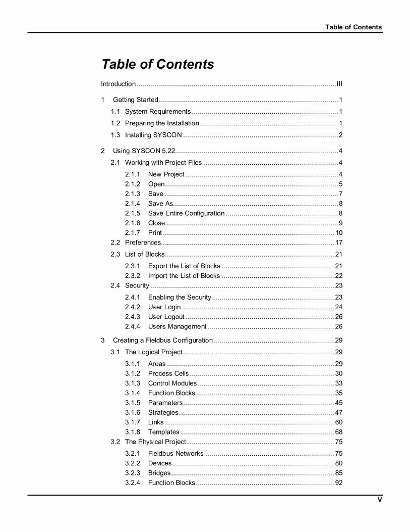
Table of Contents
V
Table of ContentsIntroduction ...................................................................................................III
1 Getting Started.........................................................................................1
1.1 System Requirements.........................................................................1
1.2 Preparing the Installation.....................................................................1
1.3 Installing SYSCON .............................................................................2
2 Using SYSCON 5.22.................................................................................4
2.1 Working with Project Files ...................................................................4
2.1.1 New Project ............................................................................42.1.2 Open......................................................................................52.1.3 Save ......................................................................................72.1.4 Save As..................................................................................82.1.5 Save Entire Configuration........................................................82.1.6 Close......................................................................................92.1.7 Print ..................................................................................... 10
2.2 Preferences...................................................................................... 17
2.3 List of Blocks.................................................................................... 21
2.3.1 Export the List of Blocks ........................................................ 212.3.2 Import the List of Blocks ........................................................ 22
2.4 Security ........................................................................................... 23
2.4.1 Enabling the Security............................................................. 232.4.2 User Login............................................................................ 242.4.3 User Logout .......................................................................... 262.4.4 Users Management ............................................................... 26
3 Creating a Fieldbus Configuration............................................................ 29
3.1 The Logical Project ........................................................................... 29
3.1.1 Areas ................................................................................... 293.1.2 Process Cells........................................................................ 303.1.3 Control Modules.................................................................... 333.1.4 Function Blocks..................................................................... 353.1.5 Parameters........................................................................... 453.1.6 Strategies............................................................................. 473.1.7 Links .................................................................................... 603.1.8 Templates ............................................................................ 68
3.2 The Physical Project ......................................................................... 75
3.2.1 Fieldbus Networks ................................................................ 753.2.2 Devices ................................................................................ 803.2.3 Bridges................................................................................. 853.2.4 Function Blocks..................................................................... 92

SYSCON - User’s Manual
VI
3.2.5 Parameters........................................................................... 983.2.6 Topology Window ................................................................. 983.2.7 Topology Link ..................................................................... 107
4 Communication .................................................................................... 110
4.1 Introduction .................................................................................... 110
4.2 Initializing Communication............................................................... 110
4.2.1 Associating Devices' IDs...................................................... 1114.2.2 Tags Assignment ................................................................ 1124.2.3 Error Log Registry............................................................... 1124.2.4 Downloading the Configuration............................................. 1134.2.5 Uploading the Configuration................................................. 1154.2.6 Live List.............................................................................. 1174.2.7 Block List............................................................................ 1194.2.8 Exporting Tags.................................................................... 1224.2.9 Exporting the Configuration.................................................. 1234.2.10 Consolidating the OPC Database ........................................ 125
5 Search Menu........................................................................................ 128
6 Properties ............................................................................................ 130
6.1 Drawing Properties ......................................................................... 130
6.2 Object Properties............................................................................ 134
7 Toolbars............................................................................................... 140
8 Device Support..................................................................................... 163
8.1 Including New DD and Capabilities File............................................ 163
8.2 Defining Manufacturers and Device Names ...................................... 164
8.3 Creating a new Capabilities File....................................................... 165
8.4 Defining a Block Mnemonic ............................................................. 165
9 Troubleshoot ........................................................................................ 167
Appendix: Step-by-Step Configuration.......................................................... 169

Syscon
1
1 Getting Started
1.1 System Requirements
1.1.1 Minimum:Operational System Windows NT 4.0 - Service Pack 6a
or Windows 2000 - Service Pack 3
Processor Pentium 233 MHz
RAM 64 MB
Free HDD Space 20 MB
Display 800x600 - 64 KColors
CD-ROM
1.1.2 Recommended:Operational System Windows NT 4.0 - Service Pack 6a
or Windows 2000 - Service Pack 3
Processor Pentium 350 MHz
RAM 128 MB
Free HDD Space 20 MB
Display 1280x1024 - True Color
CD-ROM
1.2 Preparing the Installation
It is recommended to uninstall any older versions of SYSCON before installing new versions.
Follow these steps to remove the application:
1. From the Start menu, select Settings - Control Panel.
2. Double-click the Add/Remove Programs icon. The Add/Remove Programs Propertiesdialog box will open.
3. Select the item Syscon from the list of programs.
4. Click Add/Remove.

SYSCON - Users’ Manual
2
5. Click Yes to confirm that SYSCON is to be removed.
Figure 1.1. Confirm File Deletion
6. Wait a few minutes for the uninstall program to indicate that the process is complete.Click Ok.
Figure 1.2. Uninstall Completed
1.3 Installing SYSCON
Place the SYSTEM302 CD installation at the CD-ROM drive. The Installation dialog box willopen automatically.
Click the System302 button.
Follow the instructions in the dialog boxes to complete the installation. It will install SYSCONand other programs that compound System302, such as Device Support and OLE Server.
To initialize SYSCON click the Windows Start button, at the Task Bar, point the cursor to theitem Programs, then point it to the item System302. Finally, click the item Syscon, as indicatedin the next figure:

Getting Started
3
Figure 1.3. Starting SYSCON
At the first time working with SYSCON, the License Information dialog box will appear:
Figure 1.4. License Information Dialog Box
Run the Get License software, click the Generate FaxBack button and fill in the form. Fax thecompleted FAX-BACK form to SMAR using the Fax number listed on the FaxBack.txt file.SMAR will issue the user a License Key to authorize the installed product.
Type the license key in the Syscon License Key box and click the Grant License Keys button.After the user finished granting the License Keys, click Exit.
Now, the user can finally start using SYSCON 5.22.

SYSCON - Users’ Manual
4
2 Using SYSCON 5.22
2.1 Working with Project Files
2.1.1 New Project
To create a Project File, go to the Project File menu and click New, as the following figureshows:
Figure 2.1. Project File Menu: New
The Document Type box will appear. Click the option Projects, as indicated below:
Figure 2.2. Select the File Type
The New Project dialog box will open:
1. Choose the folder where the project will be saved.
2. Type the name for the project in the File Name box.
3. Click Save. If the new project is not to be created, click Cancel.
See the following figure:
Figure 2.3. New Project Dialog Box

Using Syscon
5
SYSCON will automatically create a folder with the name the user typed for the project insidethe folder selected.
Shortcuts:
Toolbar:
Since the new project has been created, the Project window will open:
Figure 2.4. Project Window
This window contains icons for the Logical Plant - named as Area1, and for the Physical Plant- named as Fieldbus Networks. In order to begin working in the project, read first one of thesections: Creating a Logical Project or Creating a Physical Project.
2.1.2 Open
To open an existing Project, go to the File menu and click Open, as in the following figure:
Figure 2.5. Project File Menu: Open
The Open dialog box will open:
1. In the Look in box, select the folder that contains the project file to be opened.
2. Click on the project file icon or type its name in the File name box.
3. Click Open to conclude this task.

SYSCON - Users’ Manual
6
Figure 2.6. Open Project Dialog Box
Shortcuts:
Toolbar:
Checking the version
Starting from version 5.10, SYSCON verifies if the configuration file was generated by previousor later versions.
If the user is trying to open a configuration file that was generated in an older version ofSYSCON, the following message will open:
Figure 2.7. Version Mismatch Message Box
To upgrade the configuration, go to the Project File menu and click Save as, typing a newname for the project or using the same name to override the old project.
If the user upgrades the configuration converting it to the new file format, it won't be possible toopen the configuration in an older version of SYSCON again.
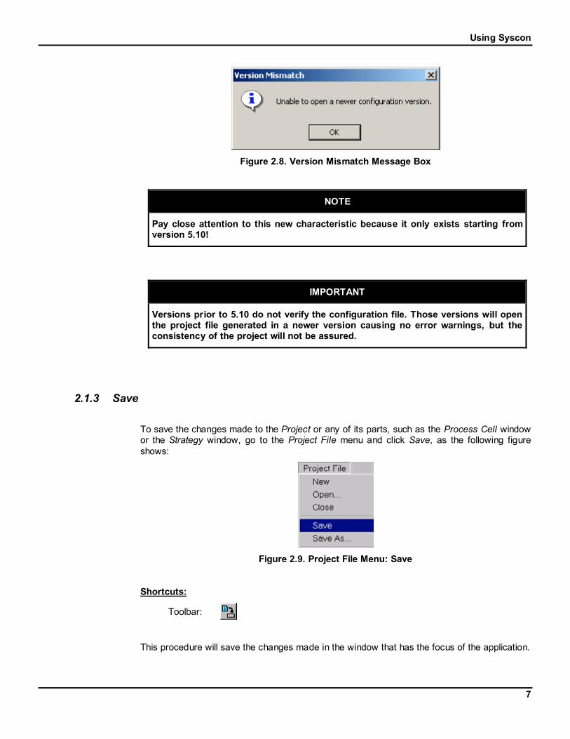
If SYSCON detects that the user is trying to open a configuration file that was generated in anewer version, the following message will open:
Using Syscon
7
Figure 2.8. Version Mismatch Message Box
NOTE
Pay close attention to this new characteristic because it only exists starting fromversion 5.10!
IMPORTANT
Versions prior to 5.10 do not verify the configuration file. Those versions will openthe project file generated in a newer version causing no error warnings, but theconsistency of the project will not be assured.
2.1.3 Save
To save the changes made to the Project or any of its parts, such as the Process Cell windowor the Strategy window, go to the Project File menu and click Save, as the following figureshows:
Figure 2.9. Project File Menu: Save
Shortcuts:
Toolbar:
This procedure will save the changes made in the window that has the focus of the application.

SYSCON - Users’ Manual
8
REMEMBER
Anytime the Project configuration changes, do not forget to save.
2.1.4 Save As
To save the Project with another name, go to the Project File menu and click Save as, as inthe following figure:
Figure 2.10. Project File Menu: Save As
The Save As dialog box will open:
Figure 2.11. Save As Dialog Box
Type a new name for the Project and click Save. A new folder will be created with the name ofthe Project file and the files related to the Project will be stored in this folder.
2.1.5 Save Entire Configuration
Use this option to save the entire plant project configuration. Go to the Project File menu andclick Save Entire Configuration, as in the following figure:

Using Syscon
9
Figure 2.12. Project File Menu: Save Entire Configuration
Shortcuts:
Toolbar:
NOTE
A Template is not part of the plant project configuration. It is necessary to set thefocus on the Template window and click the Save button, , to save the changesmade to the template configuration.
2.1.6 Close
To close the Project, click on the Project window, in case the focus is on another applicationwindow, go to the File menu and click Close, as in the following figure:
Figure 2.13. Project File Menu: Close
Or go to the Window menu and click Close All, as the following figure shows:
Figure 2.14. Window Menu: Close All

SYSCON - Users’ Manual
10
A quick way of closing a Project is to click on the Close button, , in the upper right corner ofthe Project window.
Do not forget to save the Project before closing.
2.1.7 Print
This section will show SYSCON’s printing options. These options can be found at the ProjectFile menu. See the following figure:
Printing Options
Figure 2.15. Project File Menu: Print Options
Printer Setup
This option is available to the Project window, to the Strategy window and to the Topologywindow. The user can configure page and printer options.
Click this item to open the Page Setup dialog box. See the following figure:

Using Syscon
11
Figure 2.16. Page Setup Dialog Box
At the top of the dialog box there’s an example that shows how the page layout will look like.As the options change, the page layout example will change.
Paper:
Select the size of the paper or envelope to be used in the Size box.
Select where the paper to be used is located in the printer in the Source box. Differentprinter models support different paper sources, such as the upper tray, envelope feed,and manual feed.
Orientation: select the page orientation and how the document is positioned on the page. Tosee a preview on the example page at the top of the dialog box, check the Portrait box or theLandscape box.
Margins (inches): set the printing area of the page, typing a value for the left, right, top andbottom margin.
Click on the Ok button to close the Page Setup dialog box and save the changes.
Click on the Cancel button to close the Page Setup dialog box without saving any changes.
Click on the Printer button to open the Printer Setup dialog box and change the printer options.See the following figure:

SYSCON - Users’ Manual
12
Figure 2.17. Printer Setup Dialog Box
At the Printer rectangle, select the printer in the Name box. Click the Properties button to setup options for the printer. The Printer rectangle also shows information about the selectedprinter.
Click on the Ok button to close the dialog box and save the changes.
Click on the Cancel button to close the dialog box without saving any changes.
Printing the Project Configuration
When the user clicks on the Project window and selects the option Print, or clicks the Print
button, , on the General Operation toolbar, the Print Configuration dialog box will open. Theitems of the project to be printed can be chosen. See the following figure:
Figure 2.18. Print Configuration Dialog Box
Process Control Configuration: Select this item to print the information about the ProcessControl Configuration.
General Information: prints the general information about the configuration.
Blocks: prints the information about the blocks, listed by Control Modules.

Using Syscon
13
FB Links: prints the information about the links between those blocks.
Other Components: prints further information about the Process ControlConfiguration.
Multi Link Topology: Select this item to print the information about the topology, with theBridges and Fieldbuses.
Fieldbus Configuration: Select this item to print the information about the FieldbusConfiguration.
General Information: prints the information about the configuration.
Blocks: prints the information about the blocks, listed by Devices.
FB Links: prints the information about the links between those blocks.
Other Components: prints further information about the Fieldbus Configuration.
Device List: Select this item to print the information about the Devices and their attributes.
Block List: Select this item to print the information about the Blocks.
General Information: prints the information about Blocks, their attributes and location.
Parameter Values: prints the information about the parameters configured for theBlocks.
FB Links: prints the information about the connected parameters.
FB Link List: Select this item to print the list with all of the links in the configuration.
General Information: prints the general information about the links.
Connected Parameter: prints the information about the parameters.
Schedule: Select this item to print the information about the Schedule, including both FunctionBlock Execution Schedule and Traffic Schedule.
Click on the Ok button to close this dialog box and print the project configuration.
Click on the Cancel button to close the dialog box without printing the project configuration.
Click on the Help button to open the Help window.
Printing the Strategy Drawing
When the user clicks on the Strategy window and selects the option Print, or clicks the Print
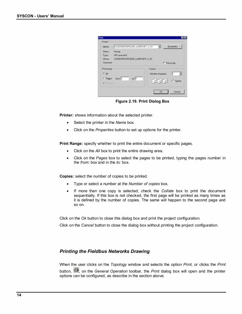
button, , on the General Operation toolbar, the Print dialog box will open and the printeroptions can be configured. See the following figure:
SYSCON - Users’ Manual
14
Figure 2.19. Print Dialog Box
Printer: shows information about the selected printer.
Select the printer in the Name box.
Click on the Properties button to set up options for the printer.
Print Range: specify whether to print the entire document or specific pages.
Click on the All box to print the entire drawing area.
Click on the Pages box to select the pages to be printed, typing the pages number inthe from: box and in the to: box.
Copies: select the number of copies to be printed.
Type or select a number at the Number of copies box.
If more than one copy is selected, check the Collate box to print the documentsequentially. If this box is not checked, the first page will be printed as many times asit is defined by the number of copies. The same will happen to the second page andso on.
Click on the Ok button to close this dialog box and print the project configuration.
Click on the Cancel button to close the dialog box without printing the project configuration.
Printing the Fieldbus Networks Drawing
When the user clicks on the Topology window and selects the option Print, or clicks the Print
button, , on the General Operation toolbar, the Print dialog box will open and the printeroptions can be configured, as describe in the section above.

Using Syscon
15
Figure 2.20. Print Dialog Box
Print to File
This option is only available on the Project window. When the user clicks this item, the PrintConfiguration dialog box will open. The user can choose the items of the project to be printed.(See the section Printing the Project Configuration above.)
When the user clicks Ok, the Save As dialog box will open:
1. In the Save in box, choose the folder where the file will be saved.
2. Type the name for the file in the File name box. The file will be saved as a Report File(*.txt).
3. Click Save to conclude this task
See the following figure:
Figure 2.21. Save As Dialog Box
To print this file, open the folder that contains the file in My Computer or Windows Explorer.Select the file icon and right-click on it to activate the popup menu. Click the option Print. Theproject configuration will be printed.

SYSCON - Users’ Manual
16
Print Preview
This option is available to the Project window, to the Strategy window, and to the Topologywindow. It allows the user to view the report before printing it. Use the Project File menu, item
Print Preview, or click the Print Preview button, , on the General Operation toolbar.
When the user clicks on the Project window and selects this item, the Print Configurationdialog box appears. The user can choose the items of the project to be printed. (See thesection Printing the Project Configuration above.)
Click Ok and the Preview window will open. See the following figure:
Figure 2.22. Print Preview: Project Window
The Preview window has its own toolbar:
Figure 2.23. Print Preview Toolbar
Read a brief explanation about the buttons:
Click this button to view the anterior page.
Click this button to view the next page.
Click this button to view the entire page in the screen.
Click this button to view two pages, at the same time, in thescreen.

Using Syscon
17
Click this button to activate the Zoom tool. Click over the pageto increase the visualization size.
Click this button to deactivate the Zoom tool. Click over thepage to decrease the visualization size.
This box shows the page(s) that are being visualized at themoment.
Click this button to print the report. It will open the Print dialogbox.
Click this button to close the Preview window and return to theSYSCON browser.
When the user clicks on the Strategy window and selects this item, the Preview windowautomatically appears. See the following figure:
Figure 2.24. Print Preview: Strategy Window
When the user clicks the Print button, , the Print dialog box appears. Click Ok to print theStrategy drawing. (See the section Printing the Strategy Drawing above.)
2.2 Preferences
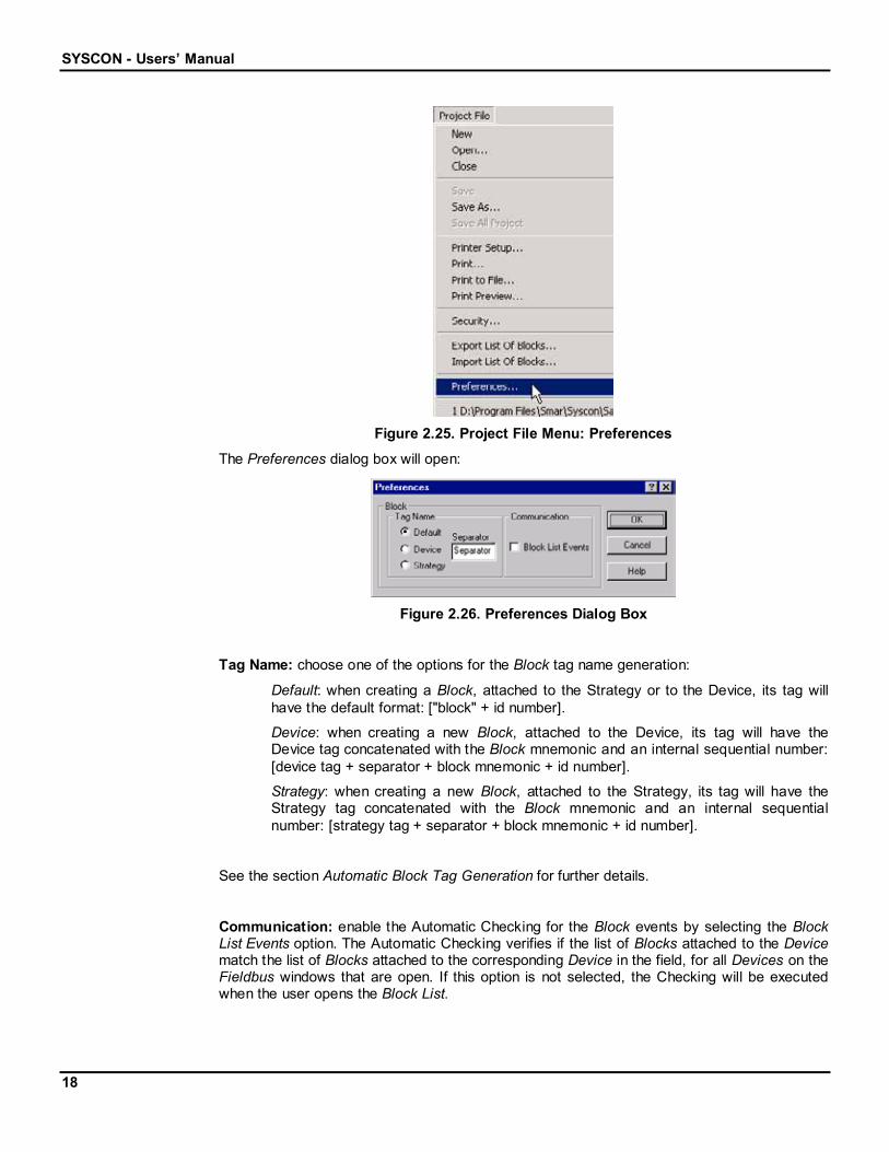
To set the Project preferences, go to the Project File menu and click Preferences, as thefollowing figure shows:
SYSCON - Users’ Manual
18
Figure 2.25. Project File Menu: Preferences
The Preferences dialog box will open:
Figure 2.26. Preferences Dialog Box
Tag Name: choose one of the options for the Block tag name generation:
Default: when creating a Block, attached to the Strategy or to the Device, its tag willhave the default format: ["block" + id number].
Device: when creating a new Block, attached to the Device, its tag will have theDevice tag concatenated with the Block mnemonic and an internal sequential number:[device tag + separator + block mnemonic + id number].
Strategy: when creating a new Block, attached to the Strategy, its tag will have theStrategy tag concatenated with the Block mnemonic and an internal sequentialnumber: [strategy tag + separator + block mnemonic + id number].
See the section Automatic Block Tag Generation for further details.
Communication: enable the Automatic Checking for the Block events by selecting the BlockList Events option. The Automatic Checking verifies if the list of Blocks attached to the Devicematch the list of Blocks attached to the corresponding Device in the field, for all Devices on theFieldbus windows that are open. If this option is not selected, the Checking will be executedwhen the user opens the Block List.

Using Syscon
19
NOTE
It is necessary to re-initialize the communication every time the Preferences for theBlock List Events option change, so the changes will take effect.
2.2.1 Automatic Block Tag Generation
When the user creates a new Block and does not define a tag to it, the tag is automaticallygenerated and assigned to the Block, based on the Preferences settings.
Default Block TagThe default tag for a new Block is describe as follow:
["Block" + id number]
Where:
Block: the default text for a Block.
id number: a sequential number that identifies the Block internally in theProject.
Block Tag Based On Device TagWhen the tag generation is based on the Device tag, if a new Block is created in a Device andthe user does not define a tag to it, then the Block tag will have the following format:
[device tag + separator + block mnemonic + id number]
Where:
device tag: the tag of the Device where the Block is attached to.
separator: a set of alphanumeric characters that separates the name ofthe Device from the name of the Block.
block mnemonic: a set of characters related to the Block type.
id number: a sequential number that identifies the Block internally in theProject.
NOTE
If the user changes the Device tag, the tag of all Blocks attached to this Device willbe updated based on the new Device tag.
If the Block is moved from one Device to another, its tag will be automaticallyupdated based on the tag of the destination Device.
SYSCON - Users’ Manual
20
If a new Block is created in the Strategy and the user does not define a tag to it, the Block tagwill be generated based on the Strategy tag since the Block is not attached to any Device yet.Once the user attaches the Block to a Device, the Block tag will be automatically updatedbased on this Device tag.
Yet, if a Block is detached from a Device, the Block tag will be updated again based on theStrategy tag.
NOTE
The general rule is if the Block is not attached to a Device but is attached to aStrategy, the Block tag will be automatically generated based on the Strategy tag,even if the tag generation method chosen is based on Device tag.
Block Tag Based On Strategy TagWhen the tag generation is based on the Strategy tag, if a new Block is created in a Strategyand the user does not define a tag to it, then the Block tag will have the following format:
[strategy tag + separator + block mnemonic + id number]
Where:
strategy tag: the tag of the Strategy where the Block is attached to.
separator: a set of alphanumeric characters that separates the nameof the Strategy from the name of the Block.
block mnemonic: a set of characters related to the Block type.
id number: sequential number that identifies the Block internally in theProject.
NOTE
If the user changes the Strategy tag, the tag of all Blocks attached to this Strategywill be updated based on the new Strategy tag.
If the Block is moved from one Strategy to another, its tag will be automaticallyupdated based on the tag of the destination Strategy.
If a new Block is created in the Device and the user does not define a tag to it, the Block tagwill be generated based on the Device tag since the Block is not attached to any Strategy yet.Once the user attaches the Block to a Strategy, the Block tag will be automatically updatedbased on this Strategy tag.
Yet, if a Block is detached from a Strategy, the Block tag will be updated again based on theDevice tag.
NOTE

Using Syscon
21
The general rule is if the Block is not attached to a Strategy but is attached to aDevice, the Block tag will be automatically generated based on the Device tag, evenif the tag generation method chosen is based on Strategy tag.
2.3 List of Blocks
SYSCON can export and import a list of Blocks in the Exchange File Format.
The user must provide the file to be exported, or imported, with the tags of the Blocks.
2.3.1 Export the List of Blocks
To export the list of Blocks, go to the Project File menu and click Export List of Blocks, as thefollowing figure shows:
Figure 2.27. Project File Menu: Export List of Blocks
The dialog box will open:
Figure 2.28. Export List of Blocks dialog box

SYSCON - Users’ Manual
22
Click the Browse button to search for the Export Template File, assuming that the user haspreviously created the file with the tags of the Blocks.
Select the option Export into a new file to create a new file for the list of Blocks. Then selectthe destination file clicking the corresponding Browse button.
Click Ok to export the list of Blocks and conclude this task.
2.3.2 Import the List of Blocks
To import the list of Blocks, go to the Project File menu and click Import List of Blocks, as thefollowing figure shows:
Figure 2.29. Project File Menu: Import List of Blocks
The dialog box will open:
Figure 2.30. Export List of Blocks dialog box
Click the Browse button to search for the Import Template File.
Click Ok to import the list of Blocks and conclude this task.

Using Syscon
23
2.4 Security
With SYSCON 5.22, it is possible to prevent the configuration file to be open by unauthorizedusers.
The users database must be installed with the application.
Only the user “Administrator” can change and configure the user’s database. TheAdministrator is the default user of the Security Manager. It can’t be removed from the list, butthe password can be changed.
2.4.1 Enabling the Security
Only the Administrator can activate and deactivate the Security Manager.
Go to the Project File menu and click Security, as the following figure shows:
Figure 2.31. Project File Menu: Security
The Security dialog box will open:
1. Type Administrator as the User Name.
2. Type the Password.
3. Click the Login button.
SYSCON - Users’ Manual
24
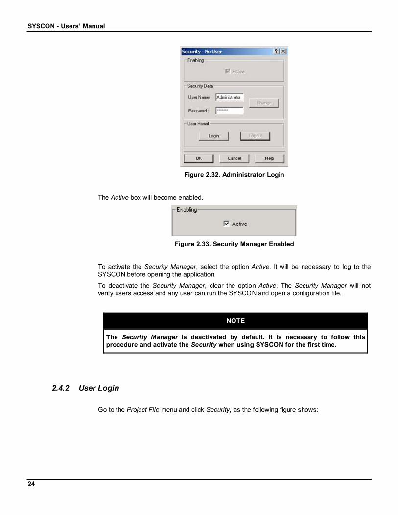
Figure 2.32. Administrator Login
The Active box will become enabled.
Figure 2.33. Security Manager Enabled
To activate the Security Manager, select the option Active. It will be necessary to log to theSYSCON before opening the application.
To deactivate the Security Manager, clear the option Active. The Security Manager will notverify users access and any user can run the SYSCON and open a configuration file.
NOTE
The Security Manager is deactivated by default. It is necessary to follow thisprocedure and activate the Security when using SYSCON for the first time.
2.4.2 User Login
Go to the Project File menu and click Security, as the following figure shows:

Using Syscon
25
Figure 2.34. Project File Menu: Security
The Security dialog box will open:
Figure 2.35. Security dialog box
1. Type the User Name.
2. Type the Password.
3. Click the Login button.
If the information is correct, the user will be logged in the application. Click Ok to close theSecurity dialog box and start using SYSCON.
REMEMBER
The User Name and the Password are case sensitive.

SYSCON - Users’ Manual
26
2.4.3 User Logout
To logout from the Security Manager, go to the Project File menu and click Security, to openthe dialog box.
Click the button Logout. A message box will open to confirm the operation.
2.4.4 Users Management
The user with the Administrator profile can change any attribute of a user.
The user with the User profile can only change the password.
To manage the users in the database, click the Change button in the Security dialog box.
Figure 2.36. Security dialog box
The dialog box will expand:
Figure 2.37. Security dialog box: User Attributes

Using Syscon
27
The Change Password area is used to change the user’s password. The password must haveat least four alphanumeric characters.
The User List displays the users that can log to the SYSCON application.
The option Enabled is used to enable or disable an user account. When an user account isdisabled, the account still exist in the database but the user will not be able to log in or run theSYSCON application.
Creating a User
Only an user with the Administrator profile can add users to the Security Manager.
To add a new user to the User List:
1. Type the login name for the user in the User Name text box.
2. Type the new password in the New text box and re-type the password in the Repeattext box.
3. Type the full name of the user in the Name text box.
4. Type a description of the user in the Descr text box.
5. Click Add to include the new user.
User Profile
The Profile option determines the type of access for the user.
Figure 2.38. Profile Options
The Adm profile allows the user to create, update or remove users from the database. It is notpossible to change the information about the Administrator.
The Mng profile allows the user to modify the password and verify the information about theother users. It is not allowed to create, update or remove users from the database.
The Usr profile allows the user to log and run the SYCON application. This user doesn’t haveaccess to the information about the other users. The Change button will be disabled.

SYSCON - Users’ Manual
28
Updating the Attributes for the User
The user with the Administrator profile can change any attribute of a user.
The user with the User profile can only change the password.
To update the attributes for a user, select the name from the User List. The information aboutthe user will be displayed in the Security dialog box.
The password, the profile, the name, the description and also the user name can be changed.
Enter the new information about the user and click the button Update to save the values.
Changing the Password
To change the password:
1. Select the name of the user in the User List.
2. Type the new password in the New text box.
3. Re-type the password in the Repeat text box.
4. Click Confirm.
5. Click Yes to apply the changes to the password.
Removing a User
Only an user with the Administrator profile can remove users from the Security Manager.
To remove a user from the database, select the user name in the User List and click the buttonRemove.
A message box will be displayed to confirm this operation. Click Yes to remove the user orclick No to cancel.
NOTE
It is not possible to remove a user that is logged to the system.

The Logical Project
29
3 Creating a Fieldbus Configuration3.1 The Logical Project
3.1.1 Areas
Changing Area Attributes
To change the Area tag, select the Area icon, go to the Edit menu and click Attributes. Oractivate the Area popup menu right-clicking its icon. Click the item Attributes. See the followingfigures:
OR
Figure 3.1. Edit Menu & Popup Menu: Area Attributes
NOTE
Using the mouse with left hand, check whether the Right Button Configuration ofthe mouse, on the Mouse Properties window, is set to open the “Context Menu”. Ifnot, use the Left Mouse Button to open the “Popup Menu”, instead of the RightMouse Button.
The Area Attributes dialog box will open. Type the new Area tag and click OK.
Figure 3.2. Area Attributes Dialog Box

SYSCON - Users’ Manual
30
3.1.2 Process Cells
Creating Process Cells
To create a Process Cell, select the Area icon, go to the Edit menu and click New ProcessCell. Or activate the Area popup menu right-clicking its icon. Click the item New Process Cell.See the following figures:
OR
Figure 3.3. Edit Menu & Popup Menu: New Process Cell
The Process Cell dialog box will open. Type the Process Cell tag and click OK.
Figure 3.4. Process Cell Dialog Box
NOTE
If a new Tag is not typed, Process Cell n will be the default, where n is a sequentialnumber for the Process Cells.
After creating the Process Cell, the Project window will look like the following figure:
Figure 3.5. Project Window

The Logical Project
31
The Process Cell has its own window: click the Process Cell icon, go to the View menu andclick Expand to activate this window. Or activate the Process Cell popup menu right-clicking itsicon. Click the item Expand, as indicated in the following figures:
OR
Figure 3.6. View Menu & Popup Menu: Expand Process Cell Window
The Process Cell window will open:
Figure 3.7. Process Cell Window
Another easy way of opening the Process Cell window is to double-click the Process Cell iconon the Project window.
Changing Process Cell Attributes
To change the Process Cell attributes, select the Process Cell icon on the Process Cellwindow, go to the Edit menu and click Attributes. Or activate the Process Cell popup menu,right-clicking its icon on the Process Cell window. Click the item Attributes. See the followingfigures:
OR
Figure 3.8. Edit Menu & Popup Menu: Process Cell Attributes
The Process Cell dialog box will open. Type the new Process Cell tag and click OK.

SYSCON - Users’ Manual
32
Figure 3.9. Process Cell Dialog Box
Deleting Process Cells
To remove a Process Cell, select its icon on the Project window, go to the Edit menu and clickDelete Process Cell. Or activate the Process Cell popup menu, right-clicking its icon andselecting the item Delete Process Cell. See the following figures:
OR
Figure 3.10. Edit Menu & Popup Menu: Delete Process Cell
A quick way of removing a Process Cell is to select its icon on the Project window and pressthe Delete key, on the keyboard.
The Warning dialog box will open. To confirm the deletion, click Yes.
Figure 3.11. Confirm Deletion Dialog Box
NOTE
It isn’t necessary to close the Process Cell window to remove it from the Project.

The Logical Project
33
3.1.3 Control Modules
Creating Control Modules
To create a Control Module, open the Process Cell window and select the Process Cell icon.Go to the Edit menu and click New Control Module. Or activate the Process Cell popup menu,right-clicking its icon on the Process Cell window. Click the item New Control Module. See thefollowing figures:
OR
Figure 3.12. Edit Menu & Popup Menu: New Control Module
The Control Module dialog box will open. Type the Control Module tag and click OK.
Figure 3.13. Control Module Dialog Box
NOTE
If a new Tag is not typed, Control Module n will be the default, where n is asequential number for the Control Modules.
The Process Cell window will look like the following figure:
Figure 3.14. Process Cell Window

SYSCON - Users’ Manual
34
Changing Control Module Attributes
To change the Control Module attributes, select its icon, go to the Edit menu and clickAttributes. Or activate the Control Module popup menu right-clicking its icon and selecting theitem Attributes. See the following figures:
OR
Figure 3.15. Edit Menu & Popup Menu: Control Module Attributes
The Control Module dialog box will open:
Figure 3.16. Control Module Attributes Dialog Box
Type the new Control Module tag.
The user can also set a value for the Stale Count. The Stale Count is the number ofMacrocycles used to signal that the data was not updated in the Link.
Click OK to close this dialog box.
Deleting Control Modules
To remove a Control Module from a Process Cell, select its icon, go to the Edit menu and clickDelete Control Module. Or activate the Control Module popup menu right-clicking its icon. Clickthe item Delete Control Module. See the following figures:

The Logical Project
35
OR
Figure 3.17. Edit Menu & Popup Menu: Delete Control Module
A quick way of removing a Control Module is to select its icon on the Process Cell window andpress the Delete key, on the keyboard.
The Warning dialog box will open. To confirm the deletion, click Yes.
Figure 3.18. Confirm Deletion Dialog Box
3.1.4 Function Blocks
Creating Blocks
To create a Function Block, select the Control Module icon on the Process Cell window, go tothe Edit menu and click New Block. Or activate the Control Module popup menu right-clickingits icon. Click the item New Block. See the following figures:
OR
Figure 3.19. Edit Menu & Popup Menu: New Block

SYSCON - Users’ Manual
36
The New Block dialog box will open:
1. Select a Block Manufacturer from the list.
2. Select a Device Type provided by the manufacturer that has been selected.
3. Select the Device Revision.
4. Select the DD Revision.
5. Select the CF Revision.
6. Select a Block Type.
7. Type a related tag for the Block.
8. Click OK.
Figure 3.20. Function Block Dialog Box
NOTE
If a new Tag is not typed, Block n will be the default, where n is a sequentialnumber for the Blocks created in the project configuration.
SYSCON uses the latest revision of the Device Revision, the DD Revision and the CFRevision as the default values for the new Block. Change these values according to theDevice being used in the plant and its revision.
The Process Cell window will look like the figure below:

The Logical Project
37
Figure 3.21. Process Cell Window
Changing Block Attributes
The only Block attribute that can be changed is the tag.
To change the Block tag, select the Block icon, go to the Edit menu and click Attributes. Oractivate the Block popup menu right-clicking its icon. Click the item Attributes. See thefollowing figures:
OR
Figure 3.22. Edit Menu & Popup Menu: Function Block Attributes
The Block Attributes dialog box will open.
Type the new Block tag and click OK.

SYSCON - Users’ Manual
38
Figure 3.23. Function Block Attributes Dialog Box
Deleting Blocks
To remove a Block from the Project, select its icon, go to the Edit menu and click Delete Block.Or activate the Block popup menu right-clicking its icon. Click the item Delete Block. See thefollowing figures:
OR
Figure 3.24. Edit Menu & Popup Menu: Delete Function Block
A quick way of removing a Block is to select its icon on the Process Cell window and press theDelete key, on the keyboard.
The Warning dialog box will open. To confirm the deletion, click Yes.
Figure 3.25. Confirm Deletion Dialog Box

The Logical Project
39
NOTE
When deleting a Block, it will be removed from the Project, even if it is attached toa Fieldbus or drawn at the Strategy window.
Attaching Blocks to the Control Module
If at least one Block has been added to the Physical Project (see section Creating Blocks inthe Physical Project), that Block can be attached to the Control Module.
On the Process Cell window, select the Control Module icon and attach the Block. Go to theEdit menu and click Attach Block. Or activate the Control Module popup menu right-clicking itsicon. Click the item Attach Block. See the following figures:
OR
Figure 3.26. Edit Menu & Popup Menu: Attach Block
The Attach Block dialog box will open. Click the down arrow to select the Block that will beattached and click OK to add the Block to the Logical Project:
Figure 3.27. Attach Block Dialog Box
Detaching Blocks from the Control Module
A Block can be only detached if it exists in the Control Module and in the Device.
SYSCON - Users’ Manual
40
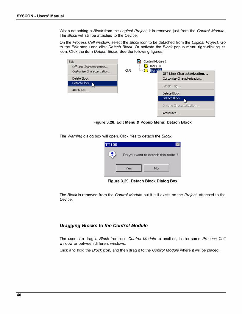
When detaching a Block from the Logical Project, it is removed just from the Control Module.The Block will still be attached to the Device.
On the Process Cell window, select the Block icon to be detached from the Logical Project. Goto the Edit menu and click Detach Block. Or activate the Block popup menu right-clicking itsicon. Click the item Detach Block. See the following figures:
OR
Figure 3.28. Edit Menu & Popup Menu: Detach Block
The Warning dialog box will open. Click Yes to detach the Block.
Figure 3.29. Detach Block Dialog Box
The Block is removed from the Control Module but it still exists on the Project, attached to theDevice.
Dragging Blocks to the Control Module
The user can drag a Block from one Control Module to another, in the same Process Cellwindow or between different windows.
Click and hold the Block icon, and then drag it to the Control Module where it will be placed.

The Logical Project
41
Figure 3.30. Dragging Blocks to the Control Module
Observe the following figure:
Figure 3.31. Process Cell Window
Before dragging a Block from a Process Cell window to the other, remember to tile thewindows to facilitate the process. In the Window menu, click Tile.
Block Off Line Characterization
Select the Block to be parameterized by clicking its icon. Go to the Edit menu and click OffLine Characterization. Or activate the Block popup menu right-clicking its icon. Click the itemOff Line Characterization. See the following figures:
OR
Figure 3.32. Edit Menu & Popup Menu: Off Line Characterization
Double-clicking the Block icon also activates the Block Characterization dialog box.
SYSCON - Users’ Manual
42
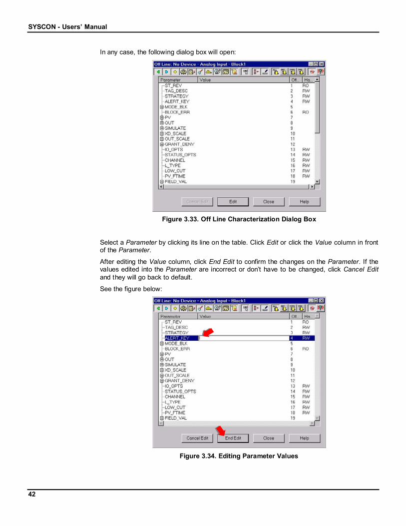
In any case, the following dialog box will open:
Figure 3.33. Off Line Characterization Dialog Box
Select a Parameter by clicking its line on the table. Click Edit or click the Value column in frontof the Parameter.
After editing the Value column, click End Edit to confirm the changes on the Parameter. If thevalues edited into the Parameter are incorrect or don’t have to be changed, click Cancel Editand they will go back to default.
See the figure below:
Figure 3.34. Editing Parameter Values

The Logical Project
43
After finishing the edits, click Close to exit the Block Characterization dialog box and go backto the Process Cell window.
For further information about the Parameters from the Blocks manufactured by SMAR, see theFunction Blocks Instruction Manual.
Customize Characterization
The user can customize the Parameters list of the Block Characterization dialog box.
Select the Block icon, at the Process Cell or Fieldbus window. Got to the Edit menu and clickCustomize Characterization. Or activate the popup menu by right-clicking the Block icon. Clickthe item Customize Characterization. See the following figures:
OR
Figure 3.35. Edit Menu & Popup Menu: Customize Characterization
The Customization dialog box will open.
Figure 3.36. Customization Dialog Box
At the Default tab, select the Parameters that are shown for the Block from the same type as
the one selected, when the user clicks the Customization by Type (Default) button, , fromthe Characterization toolbar. This customization will affect all project configurations.

SYSCON - Users’ Manual
44
At the Type tab, select the Parameters that are shown for the Block from the same type as the
one selected, when the user clicks the Customization by Type button, , from theCharacterization toolbar. This customization will affect just the current configuration.
At the Tag tab, select the Parameters that are shown just for the Block selected, when the
user clicks the Customization by Tag button, , from the Characterization toolbar. Thiscustomization will affect just the current configuration.
Block On Line Characterization
To change the Block Parameter values directly in the Devices, the user will have to proceedwith the Init Communication command first. (See the section Communication for furtherinformation)
If SYSCON is already communicating with the Plant, select the Block to be parameterized, goto the Communication menu and click On Line Characterization. Or activate the Block popupmenu right-clicking its icon and selecting the item On Line Characterization:
OR
Figure 3.37. Edit Menu & Popup Menu: On Line Characterization
The Block Characterization dialog box will open.

The Logical Project
45
Figure 3.38. On Line Characterization Dialog Box
All of the Parameters will be shown in the On Line Characterization. Use the same proceduredescribed for the Off Line Characterization to edit the Parameters values. If any Parameter isaltered, it also will be altered in the corresponding Device.
If the user changes the value for the Parameters, these Parameters will be marked with a V inthe Changed column.
To save a Parameter value that has not been edited, click the Mark to save button, , onthe Characterization toolbar. The Parameter will be marked with a V in the Changed column.Or use the Mark to save button to unmark a Parameter whose value has been changed butthe changes are not to be saved.
Click Close to exit the Block Characterization dialog box, and the following dialog box willopen:
Figure 3.39. Save Parameters Dialog Box
Click Yes to save the changes to the Configuration file.
3.1.5 Parameters
Ordering Parameters

SYSCON - Users’ Manual
46
Only Block Parameters can be ordered at the Process Cell window.
Select one Parameter icon and drag it over the other Parameter icon. The Parameter selectedfirst will be placed above the second one on the list. See the following figure:
Mouse Cursor
Figure 3.40. Ordering Parameters at the Process Cell Window
The Process Cell window will look like the following figure:
Figure 3.41. Process Cell Window
The changes made to the Parameters list at the Process Cell window will be reflected in theFieldbus window.
Deleting Parameters
To remove a Block Parameter, select the Parameter icon, go to the Edit menu and click DeleteParameter. Or activate the Parameter popup menu, by right-clicking its icon. Click the itemDelete Parameter. See the following figures:
OR
Figure 3.42. Edit Menu & Popup Menu: Delete Parameter

The Logical Project
47
A quick way of removing a Parameter is to select its icon on the Process Cell window andpress the Delete key, on the keyboard.
The Warning dialog box will open. To confirm the deletion, click Yes.
Figure 3.43. Confirm Deletion Dialog Box
3.1.6 Strategies
Creating Strategies
There will be a Strategy window for every Control Module created for a Process Cell.
To initialize a Strategy window, select the Control Module icon, go to the View menu and clickStrategy. Or activate the Control Module popup menu by right-clicking its icon. Click the itemStrategy. See the following figures:
OR
Figure 3.44. View Menu & Popup Menu: View Strategy
Double-clicking the Control Module icon also opens the Strategy window.

SYSCON - Users’ Manual
48
Figure 3.45. Strategy Window
Opening Existing Strategies
If changes have been made on a Strategy window and saved, use the steps described in thesection above to open the existing Strategy.
Then, the Strategy window should look like the example below:
Existing Strategy Window
Figure 3.46. Strategy Window
Saving Strategies
A Strategy can be saved after modifying the drawing area, for example, adding a Block.
To save a Strategy window, go to the Project File menu and click Save, as the following figureshows:

The Logical Project
49
Figure 3.47. Project File Menu: Save Strategy
Or click the Save button, , on the General Operation toolbar, under the Menu bar.
Anytime the drawing is changed, do not forget to save it.
Closing and Exiting Strategies
As the Strategy window is not an independent one, there is no exiting command. To close it,go to the Project File menu and click Close (since the focus is on this window), as the figureshows:
Figure 3.48. Project File Menu: Close Strategy
Or click the Close button, , on the upper right corner of the Strategy window.
Adding Blocks to the Strategy
There are three ways of adding Blocks to the Strategy window:
a) Dragging Blocks from the Process Cell Window
Once all Blocks have been inserted at the Control Module, the user can drag them to theStrategy window to start the linking process.

SYSCON - Users’ Manual
50
In this case, the user will work with two different windows: the Process Cell window and theStrategy window.
To organize things and make them easy to be used, the user can display the windows side byside: go to the Window menu, click Tile, and it will organize the opened windows inside theapplication.
If more than three windows are opened remember that some can be minimized and the usercan tile just the windows being worked with.
Figure 3.49. Window Menu: Tile
Now, select a Block icon, in the Process Cell window, and drag it to where it will be placed, inthe Strategy window drawing area, using the left mouse button. Observe the followingdiagram:
Selected Block
Figure 3.50. Dragging Blocks to the Strategy Window
NOTE
If the Block is dropped very close to one already added to the Strategy window, theBlock will not be drawn. It will be necessary to move the Blocks in order toorganize the Project, after they have been dropped in the Strategy window. Lookfor details in the following sections.
The figure below is an example of two dragged Blocks inside the Strategy window:

The Logical Project
51
Figure 3.51. Blocks inside the Strategy Window
The user can create more than one graphical representation of the Block in the Strategywindow by dragging the Block icon, but only one Block is attached to the Control Module.
b) Creating Blocks in the Strategy Window
In the previous case, the user already had Blocks in the Control Module. Now, a new Blockcan be created in the Strategy window.
First, click on the Strategy window and check the Strategy toolbar to be sure it is open. If it isnot, go to the Tools menu and point to the item ToolBoxes. The option Strategy should bechecked ( ).
Click the Function Block button, , on the Strategy toolbar.
When the cursor is placed in the Strategy window drawing area, it will turn into a cross. Usethe cursor to click on the drawing area.
The New Block dialog box will open:
1. Select a Block Manufacturer from the list.
2. Select a Device Type provided by the manufacturer that has been selected.
3. Select the Device Revision.
4. Select the DD Revision.
5. Select the CF Revision.
6. Select a Block Type.
7. Type a related tag for the Block.
8. Click OK.

SYSCON - Users’ Manual
52
Figure 3.52. New Block Dialog Box
The new Block will be drawn in the Strategy window and attached to the correspondingControl Module.
Figure 3.53. New Block in the Strategy Window
If another Block is to be added, from the same Manufacturer and Device Type as the previousone, right-click the drawing area. A list of Blocks types will open:
Mouse Cursor
Figure 3.54. List of Block Types

The Logical Project
53
c) Using a Template File
It is possible to use a ready Strategy, to add Blocks to the Control Module. The user will importa Template file to the Strategy window.
Open the Strategy window of the Control Module where the user will want to add the Blocks,and click the Import Template button, , on the Strategy toolbar.
If the Strategy toolbar is not open, go to the Tools menu, item Strategy, and click the optionImport Strategy Template, as indicated in the following figure:
Figure 3.55. Tools Menu: Strategy Options
The Open dialog box will open:
1. Select the folder in the Look in box.
2. Click the Template file icon or type its name in the File name box.
3. Click Open.
Observe the following figure:
Figure 3.56. Open Strategy Dialog Box
The Template will be added to the Strategy window. The user will be asked to confirm if theTemplate is to be imported to the Strategy. See the example below:

SYSCON - Users’ Manual
54
Figure 3.57. Import Strategy Template: Example
Click Ok to import the Template to the Strategy window. The Blocks, Links and Parameters willbe attached to the corresponding Control Module.
Figure 3.58. Example of a Strategy Attached to the Control Module
Click Cancel to abort the operation. The Template will not be imported to the Strategy.
NOTE
In SYSCON 5.22, a Block created or imported from a template file in the Strategywindow is automatically attached to the corresponding Control Module.
If the user is opening a configuration file from a previous version of SYSCON andthis file contains Block templates in the Strategy, these Blocks will appear in theStrategy window but will not be attached to the Control Module. Right-click theBlock in the Strategy window and select the option Attach to Model.

The Logical Project
55
Removing Blocks from the Strategy
Be very careful when removing a Block from the Strategy window! The user can remove theBlock only from the Strategy window, or the Block from the project.
Click the Select button, , on the Strategy toolbar, and select the Block to be removed, in theStrategy window. More than one Block can be selected.
Right-click the Block and select Delete from the menu:
Figure 3.59. Deleting a Block
Or press the Delete key, on the keyboard.
The Function Block Deletion dialog box will open. If more than one Block is selected, a dialogbox will open to confirm the deletion of each Block. Observe the following figure:
SelectedBlock
Figure 3.60. Function Block Deletion
Click Yes to remove the Block from the Project. Attention: clicking this button will remove theBlock from the Strategy window, from the Control Module and from the Device. Therefore, theuser will lose the Block Parameters and Links. The Block will no longer exist in the project.
In case the user wants to remove the Block only from the Strategy window, click No. Later, theuser can drag the Block again and restore Links. (See the section Restoring Links)
If the Block is not to be deleted, click Cancel.

SYSCON - Users’ Manual
56
Selecting Objects at the Strategy Windowa) Selecting One Object
To select only one object in the Strategy window, click the Select button, , on the Strategytoolbar, then click on the object.
Mouse Cursor
Figure 3.61. Selecting One Object
b) Selecting a Group of ObjectsTo select two or more objects in the Strategy window, there are two options:
Click the Select button, , on the Strategy toolbar and click on one object. Press andhold the Shift key, on the keyboard, then click each object to be selected.
Or click anywhere in the blank area of the Strategy window. While dragging themouse, a rubber band appears around the objects selected.
Mouse Cursor
Starting Point
Figure 3.62. Selecting a Group of Objects
c) Selecting All ObjectsTo select all objects drawn in the Strategy window, go to the Edit menu and click Select All. Oruse Ctrl+A, on the keyboard, to select the entire drawing area.
Changing Blocks Appearances
Changing the Block Tag

The Logical Project
57
It is possible to change the Block tag in the Strategy window. The new tag will automatically bechanged in the Process Cell window.
Follow these steps to change the Block tag:
1. Click the Strategy Modify button, , on the Strategy toolbar.
2. The mouse cursor will turn into a cross. Click on the Block label.
3. Type a new tag for the Block.
4. Click the drawing area to finish this procedure.
See the following diagram:
Mouse Cursor
Figure 3.63. Changing Block Tag
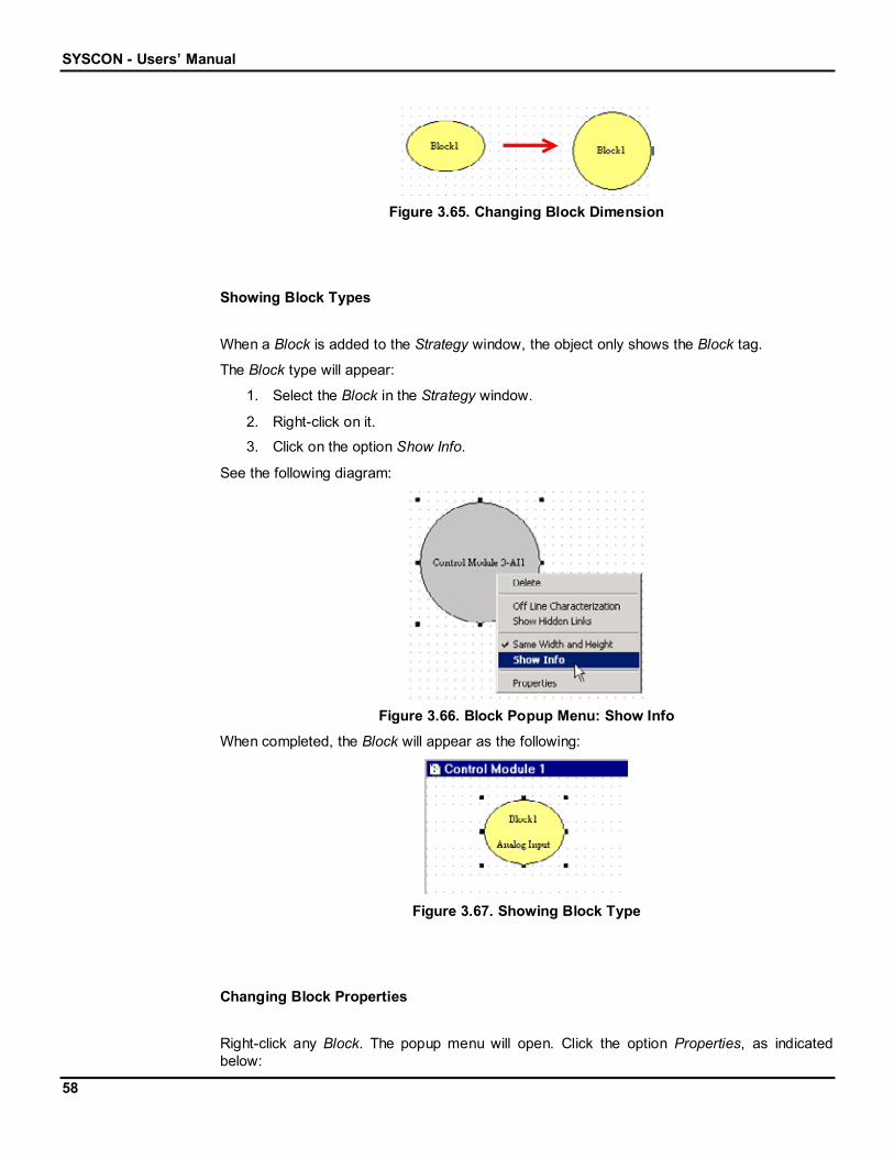
Changing Block Dimension Attributes
It is possible to make a Block have its height equal to its width:
1. Click the Select button, on the Strategy toolbar.
2. Select the Block.
3. Right-click on it and the popup menu will open.
4. Click the option Same Width and Height.
See the following figure:
Figure 3.64. Block Popup Menu: Same Width and Height
The Block will be changed as this diagram shows:
SYSCON - Users’ Manual
58
Figure 3.65. Changing Block Dimension
Showing Block Types
When a Block is added to the Strategy window, the object only shows the Block tag.
The Block type will appear:
1. Select the Block in the Strategy window.
2. Right-click on it.
3. Click on the option Show Info.
See the following diagram:
Figure 3.66. Block Popup Menu: Show Info
When completed, the Block will appear as the following:
Figure 3.67. Showing Block Type
Changing Block Properties
Right-click any Block. The popup menu will open. Click the option Properties, as indicatedbelow:

The Logical Project
59
Figure 3.68. Block Popup Menu: Properties
The following dialog box will open:
Figure 3.69. Object Properties Dialog Box
In each tab, the user can change different properties. For example, the line color can bechanged at the Line tab, item Color, and the fill color can be changed at the Fill tab, itemColor:
Figure 3.70. Changing Block Properties
Changing the Block Default Format
When a Block is added to the Strategy window, an ellipse (more exactly a circle) containingthe Block tag will represent it.
To change this representation, go to the Option menu and point to the item Function BlockIcon. Select a new format, as indicated in the figure below:

SYSCON - Users’ Manual
60
Figure 3.71. Options Menu: Function Block Icon
The next figure shows the different Block formats:
Ellipses Rectangles RoundedRectangles
Figure 3.72. Block Formats
3.1.7 Links
Creating Links
Blocks can only be linked inside the Strategy window.
To link one Block to another, click the Link button, , on the Strategy toolbar, and click on theBlock.
Mouse Cursor
Figure 3.73. Linking Blocks - Output Parameter
The Output Parameter Selection dialog box will open:

The Logical Project
61
Figure 3.74. Output Parameter Selection Dialog Box
When the cursor is placed over the OUT Parameter, a short explanation can be read, at theParameter Description text box. Click on the OUT Parameter to select it then click OK.
Return to the Strategy window, and the cursor will draw a line to represent the Link. Place themouse over the target Block and click on it.
Mouse Cursor
Figure 3.75. Linking Blocks - Input Parameter
The Input Parameter Selection dialog box will open:
Figure 3.76. Input Parameter Selection Dialog Box
When the cursor is placed on an Input Parameter, the user will read a short explanation aboutit, at the Parameter Description text box. Select the Input Parameter by clicking on it then clickOK.
SYSCON - Users’ Manual
62
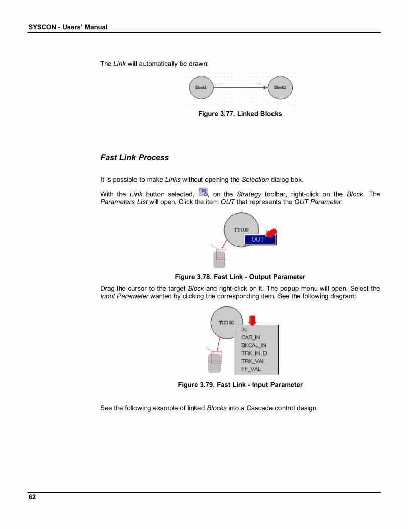
The Link will automatically be drawn:
Figure 3.77. Linked Blocks
Fast Link Process
It is possible to make Links without opening the Selection dialog box.
With the Link button selected, , on the Strategy toolbar, right-click on the Block. TheParameters List will open. Click the item OUT that represents the OUT Parameter:
Figure 3.78. Fast Link - Output Parameter
Drag the cursor to the target Block and right-click on it. The popup menu will open. Select theInput Parameter wanted by clicking the corresponding item. See the following diagram:
Figure 3.79. Fast Link - Input Parameter
See the following example of linked Blocks into a Cascade control design:

The Logical Project
63
Figure 3.80. Cascade Control Example
Link Attributes
A Link has several attributes, and can be changed. Use the Select Button, , on the Strategytoolbar, to select a Link. Right-click on the Link to activate its popup menu.
On the Labels submenu, there are three options:
Show Link Label: shows the Link label if the option has been checked.
Show Output Parameter: shows the Link Output Parameter label if the option hasbeen checked.
Show Input Parameter: shows the Link Input Parameter label if the option has beenchecked.
The following figure indicates the Labels submenu options:
Figure 3.81. Labels Menu
On the Reference Point submenu, select the reference point for the Modifying tool. There arethree options:
Ref. On Current Point: the selected handle is the reference itself.
Ref. On Previous Point: the selected handle will be placed based on the position of theprevious handle.
Ref. On Next Point: the selected handle will be placed based on the position of thenext handle.
The following figure indicates the Reference Point submenu options:

SYSCON - Users’ Manual
64
Figure 3.82. Reference Point Menu
When clicking the item Properties, the Object Properties dialog box will open. The user canchange the line and fill colors, for example.
Removing Links
To remove a Link from the Strategy window, select the Link using the Select button, , onthe Strategy toolbar. Right-click the Link and select the option Delete.
Figure 3.83. Link Menu: Delete
Or press the Delete key, on the keyboard. The Link Deletion dialog box will open:
SelectedLink
Figure 3.84. Link Deletion Dialog Box

The Logical Project
65
Be careful! Clicking Yes will remove the Link and Parameters from the drawing area and alsofrom the project. The Link will no longer exist in the Control Module or in the Device.
Click No to remove the Link only from the drawing area. In this case, it can be restored later ifnecessary. (Section Restoring Links)
If it is not to be removed, click Cancel.
Restoring Links
Consider the following Strategy:
Figure 3.85. Example of Control Strategy
As can be seen, this Strategy has two Feedback Links: one from the Block3 to the Block2 andthe second Link from the Block2 to itself.
Suppose they were deleted from the Strategy window only.
To restore those Links, follow these steps:
1. Select the Block that had its Link deleted.
2. Activate the Block popup menu, by right-clicking on it.
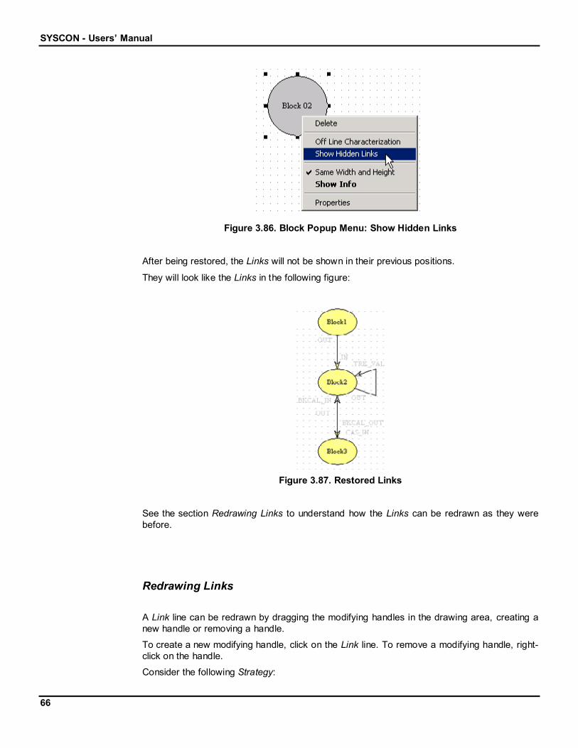
3. Click the item Show Hidden Links.
See the following diagram:
SYSCON - Users’ Manual
66
Figure 3.86. Block Popup Menu: Show Hidden Links
After being restored, the Links will not be shown in their previous positions.
They will look like the Links in the following figure:
Figure 3.87. Restored Links
See the section Redrawing Links to understand how the Links can be redrawn as they werebefore.
Redrawing Links
A Link line can be redrawn by dragging the modifying handles in the drawing area, creating anew handle or removing a handle.
To create a new modifying handle, click on the Link line. To remove a modifying handle, right-click on the handle.
Consider the following Strategy:
The Logical Project
67
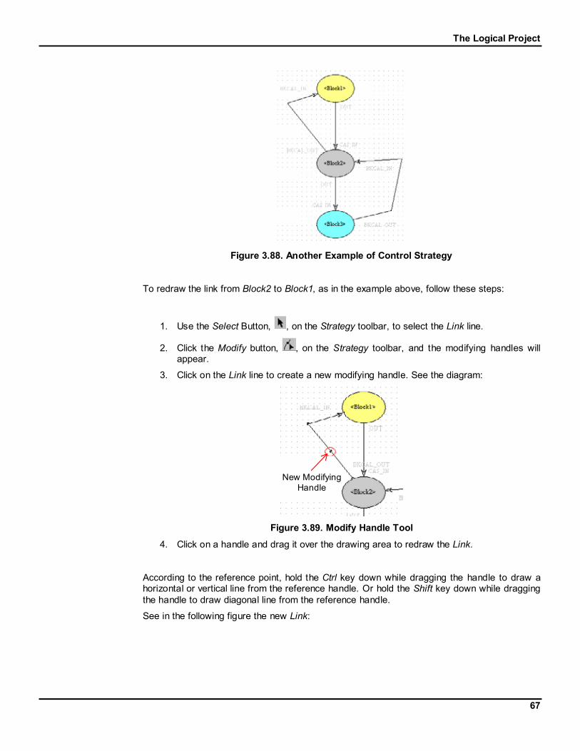
Figure 3.88. Another Example of Control Strategy
To redraw the link from Block2 to Block1, as in the example above, follow these steps:
1. Use the Select Button, , on the Strategy toolbar, to select the Link line.
2. Click the Modify button, , on the Strategy toolbar, and the modifying handles willappear.
3. Click on the Link line to create a new modifying handle. See the diagram:
New ModifyingHandle
Figure 3.89. Modify Handle Tool
4. Click on a handle and drag it over the drawing area to redraw the Link.
According to the reference point, hold the Ctrl key down while dragging the handle to draw ahorizontal or vertical line from the reference handle. Or hold the Shift key down while draggingthe handle to draw diagonal line from the reference handle.
See in the following figure the new Link:

SYSCON - Users’ Manual
68
Figure 3.90. Redrawn Links
3.1.8 Templates
It is possible to use a ready Strategy or part of it, in another project file or even in anotherProcess Cell. It is necessary to create a Template file from a Strategy Configuration. Afterwhich, just import the Template into the Control Module, change the tags and assign theBlocks to the Devices.
Using templates can speed up the Strategy development work tremendously. This will make itvery productive at the same time as the boring repetitive work is eliminated. Engineering timeand costs are reduced.
At the same time the configurations become more consistent and neater looking, and thereforeeasier to troubleshoot. Pre-configured templates also eliminate many chances of mistakes.The tedious process of instantiating Block after Block, and the agony of that forgottenParameter is a thing of the past.
Creating Templates
To create a Strategy Template file, go to the Project File menu and click New, as the followingfigure shows:
Figure 3.91. Project File Menu: New
Or click the New button, , on the General Operation toolbar, under the Menu bar.
The Logical Project
69
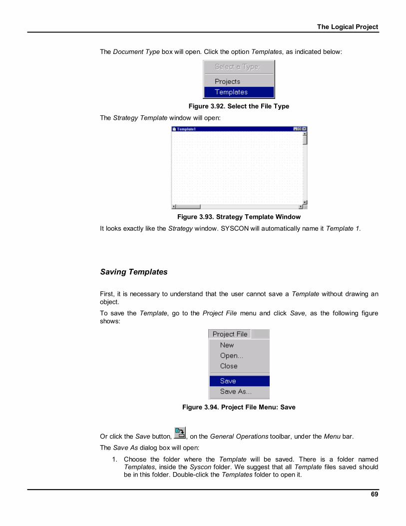
The Document Type box will open. Click the option Templates, as indicated below:
Figure 3.92. Select the File Type
The Strategy Template window will open:
Figure 3.93. Strategy Template Window
It looks exactly like the Strategy window. SYSCON will automatically name it Template 1.
Saving Templates
First, it is necessary to understand that the user cannot save a Template without drawing anobject.
To save the Template, go to the Project File menu and click Save, as the following figureshows:
Figure 3.94. Project File Menu: Save
Or click the Save button, , on the General Operations toolbar, under the Menu bar.
The Save As dialog box will open:
1. Choose the folder where the Template will be saved. There is a folder namedTemplates, inside the Syscon folder. We suggest that all Template files saved shouldbe in this folder. Double-click the Templates folder to open it.

SYSCON - Users’ Manual
70
2. Type the name for the Template in the File name box.
3. Click Save.
See the following figure:
Figure 3.95. Save As Dialog Box
Anytime a change is made to the Template drawing, do not forget to save it.
Opening Template Files
To open an existing Template, go to the File menu and click Open, as in the following figure:
Figure 3.96. Project File Menu: Open
Or click the Open button, , on the General Operations toolbar, under the Menu bar.
The Open dialog box will open:
1. In the Look in box, select the folder that contains the Template file to be opened.
2. In the Files of type box, select the Templates (.FFT) type.
3. Click the Template file icon or type its name in the File name box.
4. Click Open to conclude this task.
See the following figure:

The Logical Project
71
Figure 3.97. Open Template Dialog Box
Closing Template Files
To close the Template, click on its window, in case the focus is on another application window,go to the Project File menu and click Close, as in the following figure:
Figure 3.98. Project File Menu: Close
A quick way of closing a Template is to click on the Close button, , in the upper right cornerof the Template window.
Do not forget to save the Template before closing.
Editing Templates
The Template window has the same properties as in the Strategy window. The user can drawBlocks and Links, and can also configure Blocks Attributes. The only difference is that theBlocks will not be attached to a Control Module or a Device.
Creating BlocksTo start the editing process, add the Blocks to the drawing area, using the Function BlockTemplate button, , on the Strategy toolbar. Follow the steps described in the sectionCreating new Blocks in the Strategy window. The only difference is that it will not attach theBlocks to a Control Module.

SYSCON - Users’ Manual
72
Changing Block AttributesThe user can change Block tags, typing names related to the Block type or function. Use the
Strategy Modify button, , on the Strategy toolbar. Follow the steps described in the sectionChanging the Block Tag.
Creating LinksThen, use the Fast Link process to link the Blocks. The user can also change the Link label.(See the section Using Links)
Block CharacterizationDouble-click on a Block to open the Off-line Characterization dialog box. The user will be ableto edit the Parameters. (See the section Block Off Line Characterization)
Importing Templates into a Strategy Window
The user can only import Templates in the Strategy window. Double-click the Control Moduleicon to open the Strategy window.
To import a Template, click the Import Template button, , on the Strategy toolbar. The Opendialog box will open:
1. In the Look in box, select the folder that contains the Template file desired.
2. Click the Template file icon or type its name in the File name box.
3. Click Open to conclude this task.
See the following figure:
Figure 3.99. Open Template Dialog Box
The Template drawing will be added to the Strategy window. The user will be asked to confirmif the Template is to be imported to the Strategy. See the example below:

The Logical Project
73
Figure 3.100. Importing Template File
Click Ok to import the Template to the Strategy window. The Blocks, Links and Parameters willbe attached to the corresponding Control Module.
Exporting Templates from the Strategy Window
Select a ready Strategy, or part of it, and save it as a Template file.
In order to do this, select the Blocks and the Links that will be part of the Template. Observethe following diagram:
SelectedObjects
Figure 3.101. Selecting Blocks and Links
Click the Export Template button, , on the Strategy toolbar. The Save As dialog box willopen:
1. Choose the folder where the Template will be saved. We suggest that the Templatefile be saved in the folder Template.
2. Type the name for the Template in the File Name box.
3. Click Save.
See the following figure:

SYSCON - Users’ Manual
74
Figure 3.102. Save As Dialog Box
The Strategy selected will be saved in a file and it can be used at another time in anotherproject configuration.

The Physical Project
75
3.2 The Physical Project
3.2.1 Fieldbus Networks
Creating Fieldbuses
To create a Fieldbus, select the Fieldbus Networks icon, go to the Edit menu and click NewFieldbus. It is also possible to activate the Fieldbus Networks popup menu right-clicking itsicon. Click the item New Fieldbus. See the following figures:
OR
Figure 3.1. Edit Menu & Popup Menu: New Fieldbus
The New Fieldbus dialog box will open. Select the communication port for the Fieldbus andtype the tag in the Tag text box, and then click OK.
Figure 3.2. Fieldbus Dialog Box
NOTE
If the user does not type a Tag, the default one will be Fieldbus n, where n is asequential number for the Fieldbuses. The Fieldbus Network doesn’t have a directcorrespondence to one of the existing Process Cells.
When the user is finished creating the Fieldbus, the Project window should look like thefollowing figure:

SYSCON - Users’ Manual
76
Figure 3.3. Project Window
The Fieldbus has its own window: click the Fieldbus icon, go to the View menu and clickExpand to activate this window. Or activate the Fieldbus popup menu, right-clicking its icon.Click the item Expand, as seen in the following figures:
OR
Figure 3.4. View Menu & Popup Menu: Expand Fieldbus Window
The Fieldbus window will open:
Figure 3.5. Fieldbus Window
Another easy way to open the Fieldbus window is to double-click the Fieldbus icon on theProject window.
Changing Fieldbus Attributes
To change the Fieldbus attributes, select the Fieldbus icon on the Fieldbus window, go to theEdit menu and click Attributes. Or activate the Fieldbus popup menu, right-clicking its icon onthe Fieldbus window. Click the item Attributes. See the following figures:

The Physical Project
77
OR
Figure 3.6. Edit Menu & Popup Menu: Fieldbus Attributes
The Fieldbus dialog box will open.
Figure 3.7. Fieldbus Dialog Box
Type the new Fieldbus tag.
The user is now able to determine the time dedicated to the Background Traffic. TheBackground Traffic (in ms) will affect the refreshing time of the variables under supervision.The minimum value is 100 ms. The macrocycle is automatically updated.
To set the macrocycle:
1. Type the new value for the macrocycle.
2. Click Override.
The values for the Background Traffic and the Foreground Traffic are calculated.
Click Ok to accept these values and conclude this task.

SYSCON - Users’ Manual
78
In case the user wants to restore the macrocycle to the default value, click Default and thenclick Ok, as the following figure shows:
Figure 3.8. Fieldbus Macrocycle Default Value
After clicking Override or Default (before closing the Fieldbus dialog) the previous value of themacrocycle can be restored by clicking Cancel.
Figure 3.9. Cancel Button
NOTE
Click the button Cancel to quit the dialog box without applying the changes to theFieldbus. All modifications will be discarded, and all Fieldbus parameters will berestored to the initial state.

The Physical Project
79
Changing Information
To change the Fieldbus, select its icon on the Fieldbus window, go to the Edit menu and clickChange Info. Or activate the Fieldbus popup menu, right-clicking its icon and selecting theoption Change Info. See the following figures:
OR
Figure 3.10. Edit Menu & Popup Menu: Change Info
The Change Info dialog box will open. Select the communication port for the Fieldbus and typethe tag in the Tag text box, and then click OK.
Figure 3.11. Change Info Dialog Box
Deleting Fieldbuses
To remove a Fieldbus, select its icon on the Project window, go to the Edit menu and clickDelete Fieldbus. Or activate the Fieldbus popup menu right-clicking its icon. Click the itemDelete Fieldbus. See the following figures:
OR
Figure 3.12. Edit Menu & Popup Menu: Delete Fieldbus
A quick way of removing a Fieldbus is to select its icon on the Project window and press theDelete key, on the keyboard.
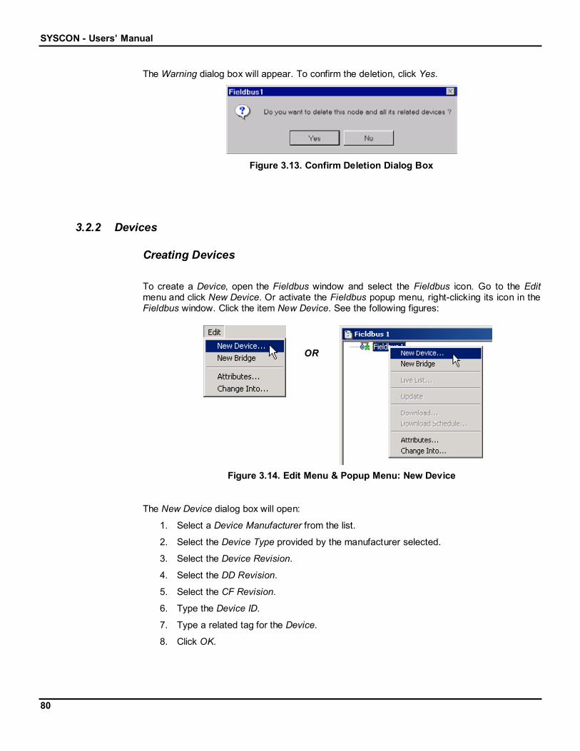
SYSCON - Users’ Manual
80
The Warning dialog box will appear. To confirm the deletion, click Yes.
Figure 3.13. Confirm Deletion Dialog Box
3.2.2 Devices
Creating Devices
To create a Device, open the Fieldbus window and select the Fieldbus icon. Go to the Editmenu and click New Device. Or activate the Fieldbus popup menu, right-clicking its icon in theFieldbus window. Click the item New Device. See the following figures:
OR
Figure 3.14. Edit Menu & Popup Menu: New Device
The New Device dialog box will open:
1. Select a Device Manufacturer from the list.
2. Select the Device Type provided by the manufacturer selected.
3. Select the Device Revision.
4. Select the DD Revision.
5. Select the CF Revision.
6. Type the Device ID.
7. Type a related tag for the Device.
8. Click OK.

The Physical Project
81
Figure 3.15. Device Dialog Box
NOTE
If the user does not type a Tag, Device n will be the default, where n is a sequentialnumber for the Devices.
The Fieldbus window should look like the following figure:
Figure 3.16. Fieldbus Window
Changing Device Attributes
To change the Device attributes, select its icon, go to the Edit menu and click Attributes. Oractivate the Device popup menu by right-clicking its icon. Click the item Attributes. See thefollowing figures:

SYSCON - Users’ Manual
82
OR
Figure 3.17. Edit Menu & Popup Menu: Device Attributes
The Device Attributes dialog box will open. Change the attributes of the Device and click OK:
Figure 3.18. Device Attributes Dialog Box
Master Backup Device
To make a Device work as a Master Backup, a Link Master should be selected:
1. Click the down arrow of the BOF Class box.
2. Select the option Link Master.
3. Click Ok.
See the following figure:

The Physical Project
83
Figure 3.19. Configuring the Link Master Device
When SYSCON is online, activate the Device menu and select the option Change BOF Class.SYSCON will promptly show a message asking to re-initialize the Device. The Device willoperate as a Link Master.
NOTE
During the download, all Master Backups in the Fieldbus Network will beconfigured with the Traffic Schedule.
Deleting Devices
To remove a Device from the Fieldbus window, select its icon, go to the Edit menu and clickDelete Device. Or activate the Device popup menu by right-clicking its icon. Click the itemDelete Device. See the following figures:
OR
Figure 3.20. Edit Menu & Popup Menu: Delete Device
A quick way of removing a Device is to select its icon on the Fieldbus window and press theDelete key, on the keyboard.
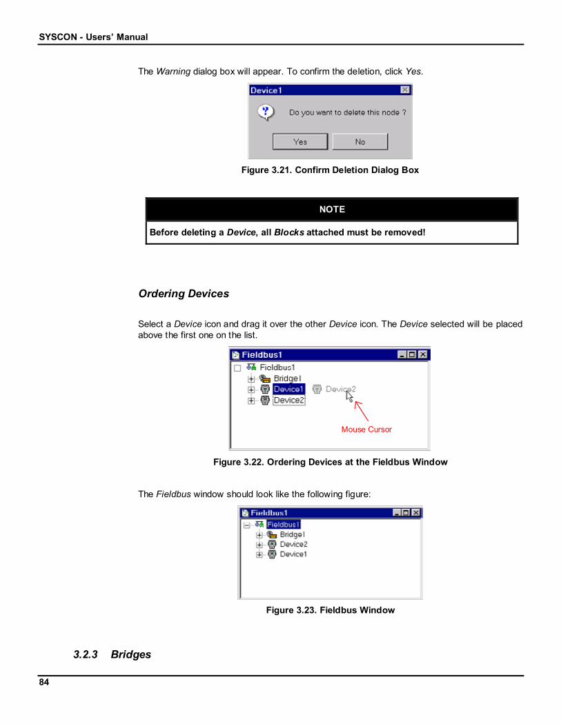
SYSCON - Users’ Manual
84
The Warning dialog box will appear. To confirm the deletion, click Yes.
Figure 3.21. Confirm Deletion Dialog Box
NOTE
Before deleting a Device, all Blocks attached must be removed!
Ordering Devices
Select a Device icon and drag it over the other Device icon. The Device selected will be placedabove the first one on the list.
Mouse Cursor
Figure 3.22. Ordering Devices at the Fieldbus Window
The Fieldbus window should look like the following figure:
Figure 3.23. Fieldbus Window
3.2.3 Bridges

The Physical Project
85
Use Bridges when the user wants a Block to supply a value to another Block but these Blocksare inside different Fieldbus Links.
Creating Bridges
To create a Bridge, select the Fieldbus icon, on the Fieldbus window, go to the Edit menu andclick New Bridge. Or activate the Fieldbus popup menu by right-clicking its icon. Click the itemNew Bridge. See the following figures:
OR
Figure 3.24. Edit Menu & Popup Menu: New Bridge
The New Bridge dialog box will open:
1. Select a Bridge Manufacturer from the list.
2. Select the Device Type provided by the manufacturer selected.
3. Select the Device Revision.
4. Select the DD Revision.
5. Select the CF Revision.
6. Type the Device ID.
7. Type a related tag for the Bridge.
8. Click OK.

SYSCON - Users’ Manual
86
Figure 3.25. Bridge Dialog Box
NOTE
If the user does not type a Tag, the default one will be Bridge n, where n is asequential number for the Bridges.
When the user is finished creating the Bridge, the Project and Fieldbus window should looklike the following figure:
Figure 3.26. Project and Fieldbus Window
In the Project window, the Bridge contains the Fieldbus.
Changing Bridge Attributes
To change the Bridge attributes, select the Bridge icon, go to the Edit menu and clickAttributes. Or activate the Bridge popup menu by right-clicking its icon. Click the itemAttributes. See the following figures:
OR
Figure 3.27. Edit Menu & Popup Menu: Bridge Attributes
The Bridge dialog box will open. Change the Bridge attributes and click Ok to conclude.
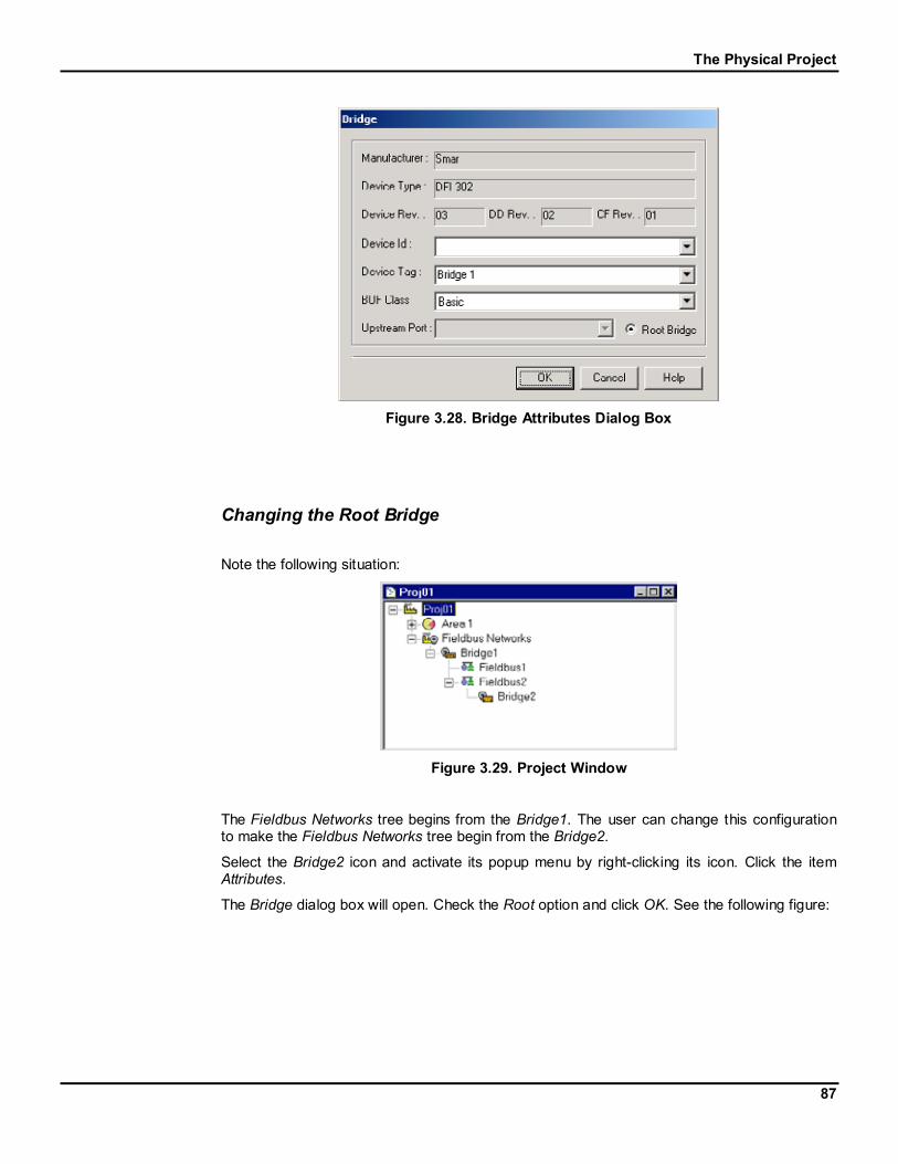
The Physical Project
87
Figure 3.28. Bridge Attributes Dialog Box
Changing the Root Bridge
Note the following situation:
Figure 3.29. Project Window
The Fieldbus Networks tree begins from the Bridge1. The user can change this configurationto make the Fieldbus Networks tree begin from the Bridge2.
Select the Bridge2 icon and activate its popup menu by right-clicking its icon. Click the itemAttributes.
The Bridge dialog box will open. Check the Root option and click OK. See the following figure:

SYSCON - Users’ Manual
88
Figure 3.30. Changing the Root Bridge
Now, the Bridge2 is the root of the Fieldbus Networks tree:
Figure 3.31. Project Window
Deleting Bridges
To remove a Bridge, select its icon on the Fieldbus window, go to the Edit menu and clickDelete Bridge. Or activate the Bridge popup menu by right-clicking its icon. Click the itemDelete Bridge. See the following figures:
OR
Figure 3.32. Edit Menu & Popup Menu: Delete Bridge

The Physical Project
89
A quick way of removing a Bridge is to select its icon and press the Delete key, on thekeyboard.
The Warning dialog box will open. To confirm the deletion, click Yes.
Figure 3.33. Confirm Deletion Dialog Box
NOTE
When a Bridge is deleted, all of the connections will also be deleted.
Connecting a Bridge to a Fieldbus
Note the following situation:
Figure 3.34. Project Window
If there have been at least two Fieldbuses added to the Physical Project, and a Bridge to oneFieldbus, the user can connect this Bridge to the other one.
Select the Bridge icon on the Project window, go to the Edit menu and click Connect to. Oractivate the Bridge popup menu by right-clicking its icon. Click the item Connect to. See thefollowing figures:

SYSCON - Users’ Manual
90
OR
Figure 3.35. Edit Menu & Popup Menu: Connect to Fieldbus
The Connect Bridge to dialog box will open:
1. Select the Fieldbus in the Tag box.
2. Select the port to connect the Fieldbus, in the Upstream Port.
3. Click Ok.
Figure 3.36. Connect Bridge Dialog Box
The following figure shows the project tree after the connection:
Figure 3.37. Project Window
The Fieldbus1 and the Fieldbus2 icon will be attached to the Bridge icon.
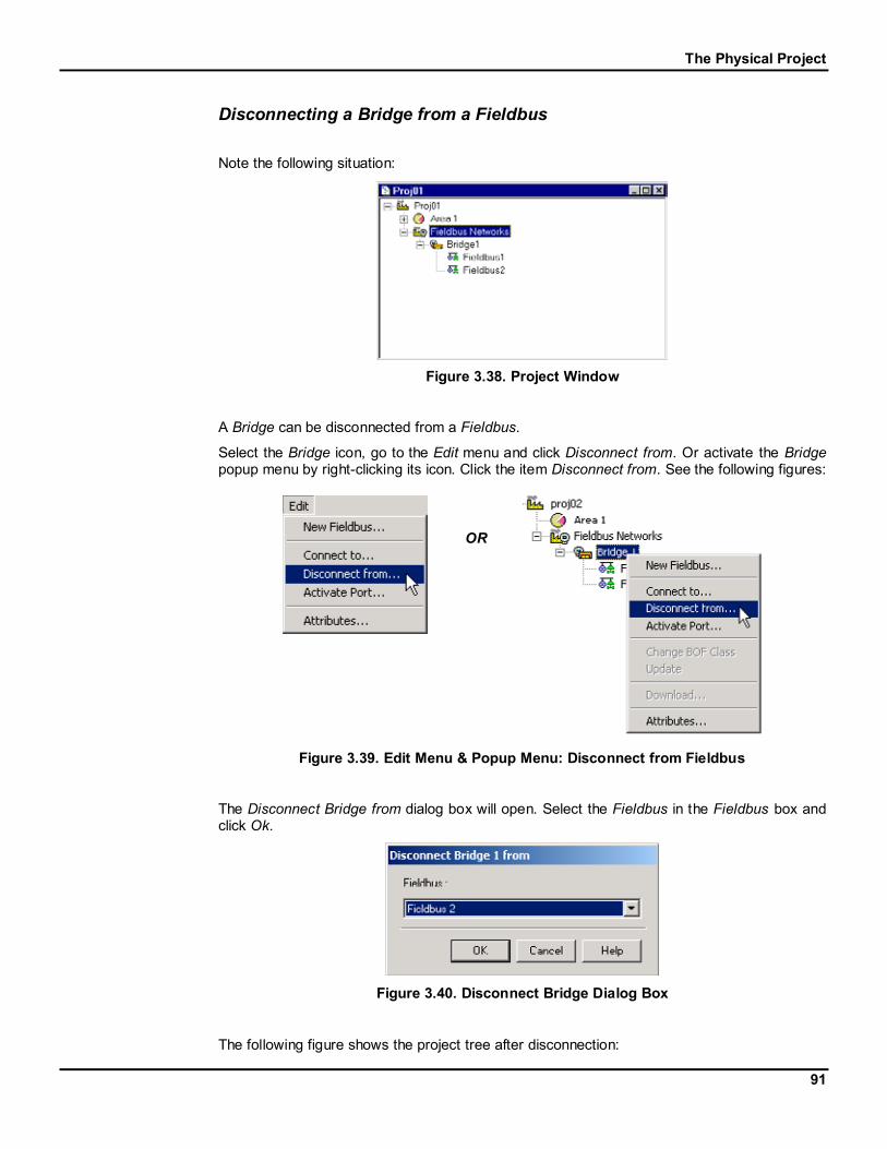
The Physical Project
91
Disconnecting a Bridge from a Fieldbus
Note the following situation:
Figure 3.38. Project Window
A Bridge can be disconnected from a Fieldbus.
Select the Bridge icon, go to the Edit menu and click Disconnect from. Or activate the Bridgepopup menu by right-clicking its icon. Click the item Disconnect from. See the following figures:
OR
Figure 3.39. Edit Menu & Popup Menu: Disconnect from Fieldbus
The Disconnect Bridge from dialog box will open. Select the Fieldbus in the Fieldbus box andclick Ok.
Figure 3.40. Disconnect Bridge Dialog Box
The following figure shows the project tree after disconnection:

SYSCON - Users’ Manual
92
Figure 3.41. Project Window
The Fieldbus2 icon will no longer be attached to the Bridge icon.
3.2.4 Function Blocks
Creating Blocks
To create a Function Block when at least one Device has already been added to theconfiguration, click the Device expansion sign, , and select the FB icon. Go to the Editmenu and click New Block. Or activate the FB popup menu, right-clicking its icon. Click theitem New Block. See the following figures:
OR
Figure 3.42. Edit Menu & Popup Menu: New Block

The Physical Project
93
The New Block dialog box will open:
1. Select a Block type.
2. Type a related tag for the Block.
3. Click OK.
Figure 3.43. Function Block Dialog Box
NOTE
If a new Tag is not typed, Block n will be the default, where n is a sequentialnumber for the Blocks created in the project configuration.
The Fieldbus window should look like the figure below:
Figure 3.44. Fieldbus Window
Once the Blocks are added, they can be attached to the Logical Project. (See sectionAttaching a Block to the Control Module)
Double-click the Block icon to open the Block Characterization dialog box and edit theParameters. (See section Block Off Line Characterization)

SYSCON - Users’ Manual
94
Changing Block Attributes
To change the Block attributes, select the Block icon, go to the Edit menu and click Attributes.Or activate the Block menu, by right-clicking its icon. Click the item Attributes. See thefollowing figures:
OR
Figure 3.45. Edit Menu & Popup Menu: Function Block Attributes
The Block Attributes dialog box will open. Type the new Block tag and click OK.
Figure 3.46. Function Block Attributes Dialog Box
Deleting Blocks
To remove a Block from a Fieldbus, select its icon, go to the Edit menu and click Delete Block.Or activate the Block popup menu, by right-clicking its icon. Click the item Delete Block. Seethe following figures:

The Physical Project
95
OR
Figure 3.47. Edit Menu & Popup Menu: Delete Function Block
A quick way of removing a Block is to select its icon and press the Delete key, on thekeyboard.
The Warning dialog box will open. To confirm the deletion, click Yes.
Figure 3.48. Confirm Deletion Dialog Box
Attaching Blocks to the Device
If at least one Block has been added to the Logical Project (see section Creating Blocks in theLogical Project), that Block can be attached to the Device.
On the Fieldbus window, select the FB icon to be attached to the Block. Go to the Edit menuand click Attach Block. Or activate the FB popup menu, by right-clicking its icon. Click the itemAttach Block. See the following figures:
OR
Figure 3.49. Edit Menu & Popup Menu: Attach Block

SYSCON - Users’ Manual
96
The Attach Block dialog box will open. Click the down arrow to select the Block to be attached.Click OK to add the Block to the Physical Project:
Figure 3.50. Attach Block Dialog Box
If no Block is to be attached, click Cancel.
Detaching Blocks from the Device
A Block can only be detached if it exists in the Control Module and in the Device.
When a Block is detached from the Physical Project, it is removed from the Device. The Blockwill still be attached to the Control Module.
On the Fieldbus window, select the Block icon to be detached from the Physical Project. Go tothe Edit menu and click Detach Block. Or activate the Block popup menu, right-clicking its icon.Click the item Detach Block. See the following figures:
OR
Figure 3.51. Edit Menu & Popup Menu: Detach Block
The Warning dialog box will open. If the Block is to be detached, click Yes.
Figure 3.52. Detach Block Dialog Box

The Physical Project
97
The Block is removed from the Device but it still exists on the Project, attached to the ControlModule.
Ordering Blocks
NOTE
The user can define the download sequence, by ordering the Devices, the Blocks,and the Parameters at the Fieldbus window.
Select a Block icon and drag it over the other Block icon. The Block selected will be placedabove the other one on the list.
Mouse Cursor
Figure 3.53. Ordering Blocks at the Fieldbus Window
The Fieldbus window should look like the following figure:
Figure 3.54. Fieldbus Window

SYSCON - Users’ Manual
98
3.2.5 Parameters
Ordering Parameters
Select a Parameter icon and drag it over the other Parameter icon. The Parameter selectedwill be placed above the other one on the list.
Mouse Cursor
Figure 3.55. Ordering Parameters at the Fieldbus Window
The Fieldbus window should look like the following figure:
Figure 3.56. Fieldbus Window
The changes made to the Parameters list at the Fieldbus window will reflect in the ProcessCell window.
3.2.6 Topology Window
Creating the Topology Drawing
To initialize the Topology window, select the Fieldbus Networks icon, go to the View menu andclick Expand. Or activate the Fieldbus Networks popup menu by right-clicking its icon. Clickthe item Expand. See the following figures:

The Physical Project
99
OR
Figure 3.57. View Menu & Popup Menu: Expand Topology Window
Double-clicking the Fieldbus Networks icon also opens the Topology window.
Figure 3.58. Topology Window
Opening Existing Topologies
If changes have been made on a Topology window and saved, use the steps described in thesection above to open the existing Topology.
Then, the Topology window should look like the example below:
Figure 3.59. Topology Window

SYSCON - Users’ Manual
100
Saving Topologies
The Topology can be saved after modifying the drawing area, for example, adding a Bridge.
To save the Topology window, go to the Project File menu and click Save, as the followingfigure shows:
Figure 3.60. Project File Menu: Save Topology
Or click the Save button, , on the General Operation toolbar, under the Menu bar.
Anytime the drawing is changed, do not forget to save it.
Closing and Exiting the Topology Window
As the Topology window is not an independent one, there is no exiting command. To close it,go to the Project File menu and click Close (since the focus is on this window), as the figureshows:
Figure 3.61. Project File Menu: Close Topology
Or click the Close button, , on the upper right corner of the Topology window.
Adding Bridges to the Topology
There are two ways of adding Bridges to the Topology window:

The Physical Project
101
a) Dragging Bridges from the Project Window
Once a Bridge has been added to the project, the user can drag it to the Topology window tostart the linking process.
In this case, the user will work with two different windows: the Project window and theTopology window.
Use the option Tile on the Window menu to organize the windows and make them easy to beused.
Figure 3.62. Window Menu: Tile
Now, click the Bridge icon, in the Project window, and drag it to where it will be placed, in theTopology window drawing area. Observe the following diagram:
Figure 3.63. Dragging Bridges to the Topology Window
b) Creating Bridges in the Topology Window
In the previous case, the user already had Bridges added to the project. Now, a new Bridgecan be created in the Topology window.
First, click on the Topology window and check the Topology toolbar to be sure it is open. If it isnot, go to the Tools menu and point to the item ToolBoxes. The option Topology should bechecked ( ).
Click the Bridge button, , on the Topology toolbar.
When the cursor is placed in the Topology window drawing area, it will turn into a cross. Usethe cursor to click on the drawing area.

SYSCON - Users’ Manual
102
The New Bridge dialog box will open:
1. Select the Bridge Manufacturer from the list.
2. Select a Device Type provided by the manufacturer that has been selected.
3. Select the Device Revision.
4. Select the DD Revision.
5. Select the CF Revision.
6. Type a related tag for the Bridge.
7. Click OK.
Figure 3.64. New Bridge Dialog Box
The graphical representation of the Bridge will be drawn in the Topology window.
Figure 3.65. New Bridge in the Topology Window
Removing Bridges from the Topology
Be very careful when removing a Bridge from the Topology window! The Bridge will beremoved from the Topology window and from the project.
Click the Select button, , on the Topology toolbar, and select the Bridge to be removed, inthe Topology window. More than one Bridge can be selected.

The Physical Project
103
Go to the Edit menu and click Delete. Or press the Delete key, on the keyboard.
The Bridge Deletion dialog box will open. If more than one Bridge is selected, a dialog box willopen to confirm the deletion of each Bridge. Observe the following figure:
Figure 3.66. Bridge Deletion
Click Ok to remove the Bridge from the Project. Attention: clicking this button will remove theBridge from the Topology window and from the Project. The Bridge will no longer exist in theproject.
If the Bridge is not to be deleted, click Cancel.
Adding a Fieldbus to the Topology
a) Creating a Fieldbus in the Topology Window
Click on the Topology window and check the Topology toolbar to be sure it is open. If it is not,go to the Tools menu and point to the item ToolBoxes. The option Topology should bechecked ( ).
Click the Fieldbus button, , on the Topology toolbar.
When the cursor is placed in the Topology window drawing area, it will turn into a cross. Usethe cursor to click on the drawing area.
The New Fieldbus dialog box will open:
1. Select the Type for the Fieldbus.
2. Type a related tag for the Fieldbus.
3. Click OK.
Figure 3.67. New Fieldbus Dialog Box

SYSCON - Users’ Manual
104
The graphical representation of the Fieldbus will be drawn in the Topology window andattached to the Fieldbus Networks icon in the Project window.
Figure 3.68. New Fieldbus in the Topology Window
b) Dragging Fieldbus from the Project Window
Once a Fieldbus has been added to the project, the user can drag it to the Topology window.
The user will work with two different windows: the Project window and the Topology window.Use the option Tile on the Window menu to organize the windows and make them easy to beused.
Figure 3.69. Window Menu: Tile
Click the Fieldbus icon, in the Project window, and drag it to where it will be placed, in theTopology window drawing area. Observe the following diagram:
Figure 3.70. Dragging a Fieldbus to the Topology Window

The Physical Project
105
Removing Fieldbuses from the Topology
When removing a Fieldbus from the Topology window, it will be removed from the Projectwindow also.
Click the Select button, , on the Topology toolbar, and select the Fieldbus to be removed, inthe Topology window. More than one Fieldbus can be selected.
Go to the Edit menu and click Delete. Or press the Delete key, on the keyboard.
The Fieldbus Deletion dialog box will open. If more than one Fieldbus is selected, a dialog boxwill open to confirm the deletion of each Fieldbus. Observe the following figure:
Figure 3.71. Fieldbus Deletion
Click Ok to remove the Fieldbus from the Project. Attention: clicking this button will removethe Fieldbus from the Topology window and from the Project. The Fieldbus will no longer existin the project.
If the Fieldbus is not to be deleted, click Cancel.
Selecting Objects at the Topology Window
a) Selecting One Object
To select only one object in the Topology window, click the Select button, , on the Topologytoolbar, then click on the object.
b) Selecting a Group of ObjectsTo select two or more objects in the Topology window, there are two options:
Click the Select button, , on the Topology toolbar and click on one object. Press and holdthe Shift key, on the keyboard, then click each object to be selected.
Or click anywhere in the blank area of the Topology window. While dragging the mouse, arubber band appears around the objects selected.

SYSCON - Users’ Manual
106
c) Selecting All ObjectsTo select all objects drawn in the Topology window, go to the Edit menu and click Select All.Or use Ctrl+A, on the keyboard, to select the entire drawing area.
Changing Properties
Right-click the Bridge or the Fieldbus and the popup menu will open. Click the optionProperties, as indicated below:
Figure 3.72. Bridge Menu: Properties
The following dialog box will open:
Figure 3.73. Object Properties Dialog Box
In each tab, the user can change different properties. See the section Object Properties.
3.2.7 Topology Link
Creating Links
To link a Bridge to a Fieldbus, click the Topology Link button, , on the Topology toolbar,and click on the Bridge. The menu will open showing the ports available for thecommunication:

The Physical Project
107
Figure 3.74. Example for the Bridge menu
Select the Port for the link. Drag the cursor to the target Fieldbus and click on it.
The Link will automatically be drawn:
Figure 3.75. Topology Link
Link Attributes
A Link has several attributes, and can be changed. Use the Select Button, , on theTopology toolbar, to select the Link. Right-click on the Link to activate its popup menu.
Select the option Show Connection Label to show the link label.
On the Reference Point submenu, select the reference point for the Modifying tool. There arethree options:
Ref. On Current Point: the selected handle is the reference itself.
Ref. On Previous Point: the selected handle will be placed based on the position of theprevious handle.
Ref. On Next Point: the selected handle will be placed based on the position of thenext handle.

SYSCON - Users’ Manual
108
When clicking the item Properties, the Object Properties dialog box will open. The user canchange the line and fill colors, for example.
Removing Links
To remove the Link, select the Link using the Select button, .
Go to the Edit menu and click Delete. Or press the Delete key, on the keyboard.
The Topology Link Deletion dialog box will open. If more than one Link is selected, a dialogbox will open to confirm the deletion of each Link. Observe the following figure:
Figure 3.76. Topology Link Deletion
Click Ok to remove the Link. If the Link is not to be deleted, click Cancel.
Redrawing Links
A Link line can be redrawn by dragging the modifying handles in the drawing area, creating anew handle or removing a handle.
To create a new modifying handle, click on the Link line. To remove a modifying handle, right-click on the handle.
According to the reference point, hold the Ctrl key down while dragging the handle to draw ahorizontal or vertical line from the reference handle. Or hold the Shift key down while draggingthe handle to draw diagonal line from the reference handle.
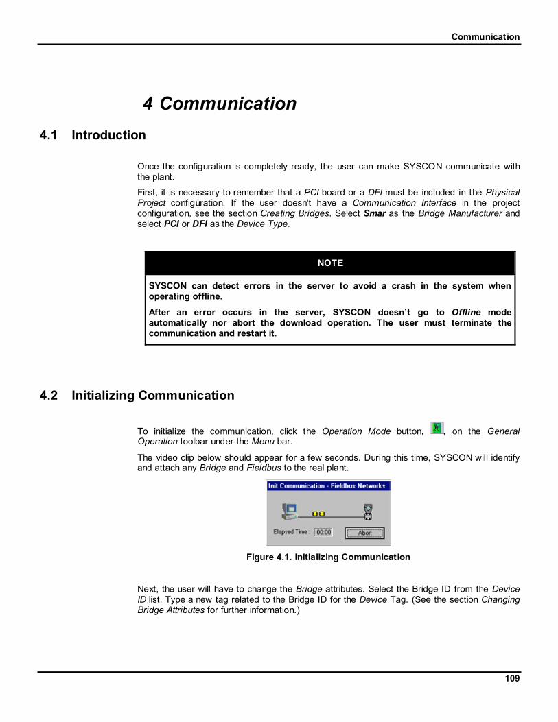
Communication
109
4 Communication4.1 Introduction
Once the configuration is completely ready, the user can make SYSCON communicate withthe plant.
First, it is necessary to remember that a PCI board or a DFI must be included in the PhysicalProject configuration. If the user doesn't have a Communication Interface in the projectconfiguration, see the section Creating Bridges. Select Smar as the Bridge Manufacturer andselect PCI or DFI as the Device Type.
NOTE
SYSCON can detect errors in the server to avoid a crash in the system whenoperating offline.
After an error occurs in the server, SYSCON doesn’t go to Offline modeautomatically nor abort the download operation. The user must terminate thecommunication and restart it.
4.2 Initializing Communication
To initialize the communication, click the Operation Mode button, , on the GeneralOperation toolbar under the Menu bar.
The video clip below should appear for a few seconds. During this time, SYSCON will identifyand attach any Bridge and Fieldbus to the real plant.
Figure 4.1. Initializing Communication
Next, the user will have to change the Bridge attributes. Select the Bridge ID from the DeviceID list. Type a new tag related to the Bridge ID for the Device Tag. (See the section ChangingBridge Attributes for further information.)

SYSCON - Users’ Manual
110
NOTE
Once the Bridge attributes match the installed Bridge attributes, this step will nolonger be necessary. SYSCON will automatically do the association.
When the Fieldbus window is opened, the following video clip should appear for a fewseconds:
Figure 4.2. Initializing Fieldbuses Communication
The user can check the Devices communicating on the channel. Click on the Fieldbus icon, goto the View menu and click Live List. The user can also right-click the Fieldbus icon to activateits popup menu. Click the item Live List.
OR
Figure 4.3. View Menu & Popup Menu: Live List
Each Fieldbus has its own Live List.
4.2.1 Associating Devices' IDs
After initializing the communication with the Fieldbuses, it is necessary to associate theDevices that are configured in the Project to the Devices in the Live List.
Open the Device dialog box to change its attributes and select the Device ID from the list. (Seethe section Changing Device Attributes for further information)
Repeat this procedure for each Device in every Fieldbus, if the Device hasn't been associatedas yet.

Communication
111
NOTE
Once the Device tag or the Device ID matches any node in the Live List, SYSCONwill automatically do the association.
4.2.2 Tags Assignment
In the previous section, one address was automatically assigned to each Device. Now, it isnecessary to assign the tags to each one of these Devices and Interfaces.
On the Fieldbus window, click on each Bridge and Device, go to the Communication menu andclick Assign Tag. The user can also activate the popup menu by right-clicking on their iconsand selecting Assign Tag. See the following figure:
Figure 4.4. Communication Menu: Assign Tag
The tag written in the configuration will be sent to the Device, see the following clip:
Figure 4.5. Assigning Tags
NOTE
To make sure that the tag assignment was successful, open the Live List of theFieldbus (or segment) and see if the tag from the Device is the one that was sent.
4.2.3 Error Log Registry
The Error Log button will be enabled if an error has been reported to SYSCON during thecommunication.
It is important to clear the Error Log Registry before downloading the configuration, becauseany eventual error that might occur during the download process will be easily detected as theError Log window pops up automatically at the occurrence of its first error.

SYSCON - Users’ Manual
112
Click the Error Log button, . It will open the Error Log window (This step will not benecessary in case this button is not enabled).
Right-click inside this window to activate the popup menu and select the option Clear Log. Seethe following figure:
Figure 4.6. Error Log Window
4.2.4 Downloading the Configuration
Configuration Download
Since the communication at the Fieldbus Networks has been initialized by clicking theOperation Mode button, it is time to download the configuration.
In the Fieldbus window, click the Fieldbus icon, go to the Communication menu and click theitem Download. Or right-click on the Fieldbus icon to activate its popup menu and select theitem Download. See the following figures:
OR
Figure 4.7. Communication Menu & Popup Menu: Download
While the configuration is being downloaded to the plant, the following dialog will be prompted:

Communication
113
Figure 4.8. Downloading the Configuration
It is necessary to repeat this procedure for each Fieldbus (or segment).
Partial Download
In case a Device failed or after replacing a Device, the user can run a partial download for thisDevice, provided that it doesn’t change the configuration. When the configuration is changed,it's up to the user to run a partial download for all Devices affected by the change. Otherwise,the partial download can produce unpredictable results.
Note that changes in one Device may affect others. If the user changes an external link forinstance, it is affecting at least two Devices besides the LAS.
The partial download speeds up the download process. However, in case of doubts, it isstrongly recommended using the complete download.
In the Fieldbus window, click on the Device icon, go to the Communication menu and click theitem Update. Or right-click on the Device icon to activate its popup menu and select the itemUpdate. See the following figures:
OR
Figure 4.9. Communication Menu & Popup Menu: Update
The replaced Device tag will get out of the Live List and the new Device tag will appear.
Now the user can run the partial download.

SYSCON - Users’ Manual
114
In the Fieldbus window, click on the Device icon, go to the Communication menu and click theitem Download. Or right-click on the Device icon to activate its popup menu and select the itemDownload. See the following figures:
OR
Figure 4.10. Communication Menu & Popup Menu: Download
4.2.5 Uploading the Configuration
Configuration Upload
This section describes the steps to upload the configuration from the Field Devices to theProject File. It is necessary to initialize the communication, before executing the Upload.
In the Project window, click on the Fieldbus Networks icon, go to the Communication menuand click the item Upload. Or right-click on the Fieldbus Networks icon to activate its popupmenu and select the item Upload. See the following figures:
OR
Figure 4.11. Communication Menu & Popup Menu: Upload
The Upload dialog box will open:
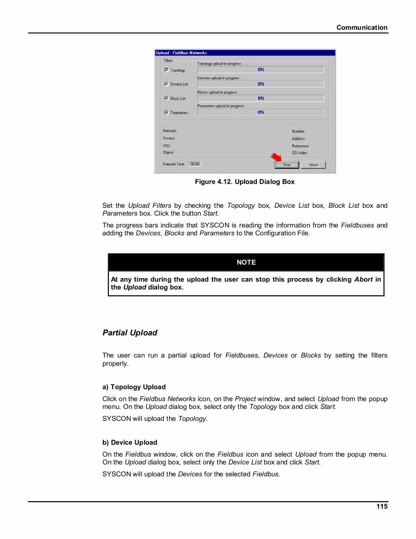
Communication
115
Figure 4.12. Upload Dialog Box
Set the Upload Filters by checking the Topology box, Device List box, Block List box andParameters box. Click the button Start.
The progress bars indicate that SYSCON is reading the information from the Fieldbuses andadding the Devices, Blocks and Parameters to the Configuration File.
NOTE
At any time during the upload the user can stop this process by clicking Abort inthe Upload dialog box.
Partial Upload
The user can run a partial upload for Fieldbuses, Devices or Blocks by setting the filtersproperly.
a) Topology Upload
Click on the Fieldbus Networks icon, on the Project window, and select Upload from the popupmenu. On the Upload dialog box, select only the Topology box and click Start.
SYSCON will upload the Topology.
b) Device Upload
On the Fieldbus window, click on the Fieldbus icon and select Upload from the popup menu.On the Upload dialog box, select only the Device List box and click Start.
SYSCON will upload the Devices for the selected Fieldbus.
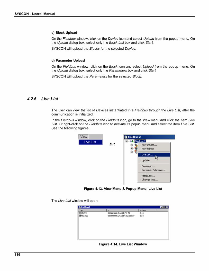
SYSCON - Users’ Manual
116
c) Block Upload
On the Fieldbus window, click on the Device icon and select Upload from the popup menu. Onthe Upload dialog box, select only the Block List box and click Start.
SYSCON will upload the Blocks for the selected Device.
d) Parameter Upload
On the Fieldbus window, click on the Block icon and select Upload from the popup menu. Onthe Upload dialog box, select only the Parameters box and click Start.
SYSCON will upload the Parameters for the selected Block.
4.2.6 Live List
The user can view the list of Devices instantiated in a Fieldbus through the Live List, after thecommunication is initialized.
In the Fieldbus window, click on the Fieldbus icon, go to the View menu and click the item LiveList. Or right-click on the Fieldbus icon to activate its popup menu and select the item Live List.See the following figures:
OR
Figure 4.13. View Menu & Popup Menu: Live List
The Live List window will open:
Figure 4.14. Live List Window
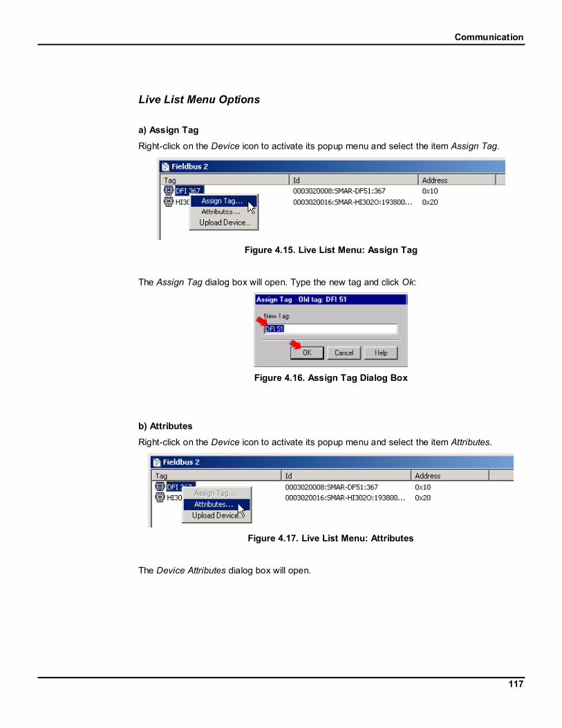
Communication
117
Live List Menu Options
a) Assign Tag
Right-click on the Device icon to activate its popup menu and select the item Assign Tag.
Figure 4.15. Live List Menu: Assign Tag
The Assign Tag dialog box will open. Type the new tag and click Ok:
Figure 4.16. Assign Tag Dialog Box
b) Attributes
Right-click on the Device icon to activate its popup menu and select the item Attributes.
Figure 4.17. Live List Menu: Attributes
The Device Attributes dialog box will open.

SYSCON - Users’ Manual
118
Figure 4.18. Device Attributes Dialog Box
c) Upload Device
Right-click on the Device icon to activate its popup menu and select the item Upload Device.
Figure 4.19. Live List Menu: Upload Device
The following dialog box will open while the Device is being uploaded.
Figure 4.20. Uploading Device
4.2.7 Block List
The user can view the list of Blocks instantiated in a Device through the Block List, after thecommunication is initialized.
In the Fieldbus window, click on the FB icon, go to the View menu and click the item Block List.Or right-click on the FB icon to activate its popup menu and select the item Block List. See thefollowing figures:

Communication
119
OR
Figure 4.21. View Menu & Popup Menu: Block List
The Block List window will open:
Figure 4.22. Block List Window
Block List Menu Options
a) Assign Tag
Right-click on the Block icon to activate its popup menu and select the item Assign Tag.
Figure 4.23. Block List Menu: Assign Tag
The Assign Tag dialog box will open. Type the new tag and click Ok:
Figure 4.24. Assign Tag Dialog Box
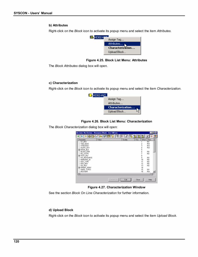
SYSCON - Users’ Manual
120
b) Attributes
Right-click on the Block icon to activate its popup menu and select the item Attributes.
Figure 4.25. Block List Menu: Attributes
The Block Attributes dialog box will open.
c) Characterization
Right-click on the Block icon to activate its popup menu and select the item Characterization.
Figure 4.26. Block List Menu: Characterization
The Block Characterization dialog box will open:
Figure 4.27. Characterization Window
See the section Block On Line Characterization for further information.
d) Upload Block
Right-click on the Block icon to activate its popup menu and select the item Upload Block.

Communication
121
Figure 4.28. Block List Menu: Upload Block
The Block will be created in the corresponding Device.
4.2.8 Exporting Tags
To enable the on-line communication with the Parameters of the Function Blocks, the user willhave to generate a file containing all tags (Devices and Function Blocks) present in theconfiguration.
On the Project window, click on the Project icon, go to the Export menu and click Tags. Oractivate the popup menu by right-clicking on the Project icon. Click the item Export Tags.
Figure 4.29. Export Menu: Export Tags
The Save Tag Info dialog box will open. Select the Taginfo.ini file and click Save.
Figure 4.30. Save Tag Info Dialog Box

SYSCON - Users’ Manual
122
NOTE
Every time any tag is changed in the configuration, it is necessary to repeat theExport Tag procedure. Otherwise, the supervision of the new tag will not beallowed.
To automatically update the Taginfo.ini file, click on the Project icon, go to the Export menuand click Update OPC Database. Or activate the popup menu, right-clicking on the Projecticon. Click the item Update OPC Database.
Figure 4.31. Export Menu: Update OPC Database
The file promptly will be updated.
NOTE
If there are two or more configuration files, the tag lists from these sources mustbe consolidated in a single list, so the OPC Server can use the entire list of tags toprovide the information requested by any OPC client application.
The user must assure that the tags used in all of the configuration files are unique. If there areduplicated tags, only one tag will be exported to the Taginfo.ini file.
When the user exports the tags or updates the OPC database of a configuration that has aconsolidated tag list, the consolidated list will be updated with the tag list corresponding to theconfiguration current open.
4.2.9 Exporting the Configuration
The user can export the project configuration to an existing database.
On the Project window, click the Project icon. Go to the Export menu and click Configuration.Or activate the popup menu, by right-clicking the project icon. Click the item ExportConfiguration.

Communication
123
Figure 4.32. Export Menu: Export Configuration
The Select Data Source dialog box will open.
On the File Data Source tab, select the source that describes the driver that is to beconnected. The user can use any file data source that refers to an ODBC driver, which isinstalled on the machine.
Double-click the data source icon to select the driver. See the following figure:
Figure 4.33. Select Data Source Dialog Box
Or the user can also use the Machine Data Source tab.
The Machine Data Source is specific to the machine, and cannot be shared. According to theType column: "User" data sources are specific to a user on the machine; "System" datasources can be used by all users on the machine, or by a system-wide service.
Double-click the data source name to select the machine. See the following figure:

SYSCON - Users’ Manual
124
Figure 4.34. Select Data Source Dialog Box
The Select Workbook dialog box will appear:
Figure 4.35. Select Workbook Dialog Box
Select the folder where the data file is and double-click the workbook icon.
The project configuration will be saved to the workbook file.
4.2.10 Consolidating the OPC Database
If the user is working with two or more configuration files, the tag lists from these source filesmust be consolidated in a single list.
On the Project window, click on the Project icon, go to the Export menu and click ConsolidateOPC Database. Or activate the popup menu right-clicking on the Project icon. Click the itemConsolidate OPC Database.

Communication
125
OR
Figure 4.36. Export Menu & Popup Menu: Consolidate OPC Database
The Consolidate OPC Database dialog box will open.
Figure 4.37. Consolidate OPC Database dialog box
Adding a Configuration
To add the current configuration to the consolidate list, click Add This. A dialog box will open toconfirm the operation. Click Yes to include the tag list of the current configuration to the tag listof the OPC Server. The name of the configuration will be added to the list of configurations.
To add another configuration to the list, it is necessary to open the configuration in theSYSCON application and repeat this procedure.
Removing a Configuration
To remove a configuration from the consolidate list, select the name of the configuration in theConfigurations list and click Remove. A dialog box will open to confirm the operation. Click Yesto remove the selected configuration from the tag list of the OPC Server. The name of theconfiguration will be removed from the list of configurations.

SYSCON - Users’ Manual
126
Updating a Configuration
If the tag list of a configuration that has been consolidated changes, it will be necessary toupdate the tag list of the OPC Server.
Open the configuration file that had the tag list updated. Right-click the Project icon and selectthe item Consolidate OPC Database to open the dialog box.
Click the button Update This. A dialog box will open to confirm the operation. Click Yes toupdate the tag list in the OPC Server.
NOTE
This procedure has the same functionality of the Export Tags and Update OPCDatabase options, in the Export menu.
Clearing the Consolidated List
To reset the list of consolidated configurations and remove all of the tag lists from the OPCServer, open any configuration file in the SYSCON application. Right-click the Project icon andselect the item Consolidate OPC Database to open the dialog box.
The list of configurations that have been consolidated will be displayed.
Click the button Clear All. A dialog box will open to confirm the operation. Click Yes to resetthe consolidated tag list of the OPC Server.

SYSCON - Users’ Manual
128
5 Search MenuThe user can search for Devices and Blocks on the project configuration.
Go to the Search menu and click Find. See the following figure:
Figure 5.1. Search Menu: Find
The Find Tags dialog box will open:
Figure 5.2. Find Tags Dialog Box
To search for a Device, click the Device tab, and type its tag on the Tag to Find text box, orselect the tag on the Tags box. The Device‘s location will be shown on the Fieldbus NetworksLocation box.
See the following example:
1. Type the tag of the Device.
2. The Fieldbus Networks location will be indicated.

Search Menu
129
Figure 5.3. Searching for Devices
3. Click Ok to open the Fieldbus window and localize the Device.
To search for a Block, click the Block tab, and type its tag on the Tag to Find text box, or selectthe tag on the Tags box. The Block‘s location will be shown on the Fieldbus Networks Locationbox. The Physical Location box shows to which Process Cell and Control Module the Block isattached. See the following example:
Block Location
Figure 5.4. Searching for Blocks
Click Ok to open the Fieldbus window and localize the Block.

SYSCON - Users’ Manual
130
6 Properties6.1 Drawing Properties
This section presents a brief explanation about the drawing properties. For example, the usercan change the number of pixels that represents a logical measure unit, the background andthe grid colors, or can choose a background image to be placed at the drawing area at theStrategy window.
To change the drawing properties go to the Options menu and click Drawing Properties. Oractivate the popup menu, right-clicking on the drawing area on the Strategy window. Click theitem Drawing Properties.
Figure 6.1. Options Menu: Drawing Properties
The Drawing Properties dialog box will open:
Figure 6.2. Drawing Properties Dialog Box
The Apply button is used to apply the changes to the object, so the user can have a preview ofhow the changes affected it.
Click Ok, the changes will be made and the dialog box will be closed.
If the user clicks Cancel before clicking the Apply button, the changes will be lost.
In each tab, different properties can be changed. They are explained in the following sections.

Properties
131
General Tab
At the General tab, the user can change the drawing visualization and the total extents of thedrawing.
Figure 6.3. Drawing Properties Dialog Box: General Tab
The Logical Units per Pixel Relationship rectangle defines:
How many X units will correspond to a determined number of pixels, increasing ordecreasing the numbers at the X boxes. This will increase the width view.
How many Y units will correspond to a determined number of pixels, increasing ordecreasing the numbers at the Y boxes. This will increase the height view.
Selecting the Same X and Y Relationship box, any change done to the X variable, concerningthe number of pixels that will represent a logical measure unit, will also be done automaticallyto the Y variable. This will maintain the correct proportion.
At the Total Extents rectangle choose to represent the drawing:
In Units: the user will be working in a determined area independently from the papersize, except when printing the drawing. In this case, the software will make acorrespondence, independent of the number of pages it will take. Increase ordecrease the number of horizontal and vertical units, typing or selecting a number atthe X and Y boxes.
In Printable Pages: the drawing will be presented in a page format, according to thePrint Setup definitions and pre-defined Units size. Define how many side-by-sidepages there will be at the Horz box, and how many pages, one after the othervertically, there will be at the Vert box.
Colors Tab
At the Colors tab, the user can change the background and the grid colors of the drawing area.

SYSCON - Users’ Manual
132
Figure 6.4. Drawing Properties Dialog Box: Colors Tab
At the Background rectangle, click the filled rectangle to select the background color. TheColor box will open. Click the color at the palette and click OK.
At the Grid rectangle, click the filled rectangle to select the grid color. The Color box will open.Click the color at the palette and click OK.
Helper Tools Tab
At the Helper Tools tab, the user can enable or disable gridlines, change the spacing betweengridlines and type the zoom factor for the drawing view.
Figure 6.5. Drawing Properties Dialog Box: Helper Tools Tab
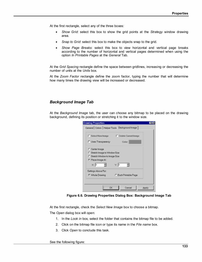
Properties
133
At the first rectangle, select any of the three boxes:
Show Grid: select this box to show the grid points at the Strategy window drawingarea.
Snap to Grid: select this box to make the objects snap to the grid.
Show Page Breaks: select this box to view horizontal and vertical page breaksaccording to the number of horizontal and vertical pages determined when using theoption In Printable Pages at the General Tab.
At the Grid Spacing rectangle define the space between gridlines, increasing or decreasing thenumber of units at the Units box.
At the Zoom Factor rectangle define the zoom factor, typing the number that will determinehow many times the drawing view will be increased or decreased.
Background Image Tab
At the Background Image tab, the user can choose any bitmap to be placed on the drawingbackground, defining its position or stretching it to the window size.
Figure 6.6. Drawing Properties Dialog Box: Background Image Tab
At the first rectangle, check the Select New Image box to choose a bitmap.
The Open dialog box will open:
1. In the Look in box, select the folder that contains the bitmap file to be added.
2. Click on the bitmap file icon or type its name in the File name box.
3. Click Open to conclude this task.
See the following figure:

SYSCON - Users’ Manual
134
Figure 6.7. Open Image Dialog Box
Check the Delete Current Image box to delete the bitmap currently used on the drawing.
Check the Uses Transparency box to make one color of the bitmap transparent. Click theColor rectangle to open the palette and select a color.
At the second rectangle, the user defines the view properties, such as placing image at adetermined position, or stretching it to the window size.
Select one of the options:
Center Image: places the bitmap at the center of the drawing area.
Stretch Image to Window Size: stretches the bitmap until it fits to the window size.
Stretch Window to Image Size: stretches the document window until it fits the bitmap.
Place Image At: defines a position for the bitmap inside the drawing area. To definethe horizontal position, type or select a value at the X: box. To define the verticalposition, type or select a value at the Y: box.
At the Settings Above For: rectangle, the user can apply the bitmap position to the wholedrawing area, checking the Whole Drawing box, or to each printable page, checking the EachPrintable Page box.
6.2 Object Properties
This section presents a brief explanation about the object properties. For example, the usercan change the position, the size, the line color, the fill color and the text attributes of a Blockdrawn at the Strategy window.
To change the properties of an object, select the object at the Strategy window, go to theOptions menu and click Object Properties. Or activate the object menu, by right-clicking on it.Click the item Properties.

Properties
135
Figure 6.8. Options Menu & Popup Menu: Object Properties
The Object Properties dialog box will open:
Figure 6.9. Object Properties Dialog Box
The Apply button will be used to apply the changes to the object, so the user can have apreview of how the changes affected it.
Click Ok, the changes will be made and the dialog box will be closed.
If the user clicks Cancel before clicking the Apply button, the changes will be lost.
The Line, Fill and Text Attributes tabs have three additional buttons:
Inherit: this button turns back the default configuration.
Revert: this button turns back the anterior configuration.
Set As Default: this button makes the current configuration the default.
Those buttons will be available when changing at least one object attribute.
In each tab, different properties can be changed. They are explained in the following sections.
General Tab
At the General tab, the user can precisely change the position and the size of the selectedobject. The Status bar, at the bottom of the SYSCON window, displays information about thelocation of the cursor, while moving the cursor on the Strategy window.

SYSCON - Users’ Manual
136
Figure 6.10. Object Properties Dialog Box: General Tab
At the Position rectangle define:
The horizontal position of the object, typing or selecting a number at the X box.
The vertical position of the object, typing or selecting a number at the Y box.
At the Size rectangle define:
The width of the object, typing or selecting a number of horizontal units at the Widthbox. (The minimum width is 75 units)
The height of the object, typing or selecting a number of vertical units at the Heightbox. (The minimum height is 44 units)
Line Tab
At the Line tab, the user can change all line attributes of the selected object.
Figure 6.11. Object Properties Dialog Box: Line Tab

Properties
137
At the Thickness rectangle, the user can define the line thickness, typing or selecting anumber. See the following examples of line thickness:
Thickness 1 Thickness 4
Figure 6.12. Line Thickness Examples
At the Style rectangle, click the down arrow to select the line style. Choose a dashed line, adoted line, a dashed-dot line, a dashed-dot-dot line, or a solid line, which is the SYSCONdefault. See the following examples of line styles:
Solid Line Dashed-DotLine
Figure 6.13. Line Style Examples
At the Color rectangle, click the filled rectangle to select the line color. The Color box will open.Click the color at the palette then click OK. See the following examples of line colors:
Black Line Red Line
Figure 6.14. Line Color Examples
Fill Tab
At the Fill tab, the user can change all fill attributes of the selected object.

SYSCON - Users’ Manual
138
Figure 6.15. Object Properties Dialog Box: Fill Tab
Select one of the fill effects: Hollow, Solid or Hatched.
The Style rectangle will be available when selecting the Hatched fill style. Choose a horizontal,a vertical, a f diagonal, a d diagonal, a cross, or a diagonal cross hatch. See the followingexamples of line styles:
Hollow Solid FDiagonal
DiagonalCross
Figure 6.16. Fill Effects Examples
The Color rectangle will be available for the Solid and Hatched fill style. Click the filledrectangle. The Color box will open. Click the color at the palette then click OK. See thefollowing examples of fill colors:
Figure 6.17. Fill Color Examples
Text Attributes Tab
At the Text Attributes tab, the user can change the text attributes of the selected object.

Properties
139
Figure 6.18. Object Properties Dialog Box: Text Attributes Tab
Select one of these options:
Full Quality: this option limits the text to work with Windows restricted attributes. Theuser won’t be able to treat the text as if it were an object, resizing it any way or evenchanging its line or fill attributes.
Fully Resizable: this option allows the user to modify any text attribute as if it were anobject.
Choose the background style for the text:
Transparent: set a transparent background for the text.
Opaque: set a filled background for the text.
The Background Color rectangle is available for the Opaque option. Click the color rectangleand the Color box will open. Choose the color and click Ok. See the following example:
TransparentBackground
Opaque WhiteBackground
Figure 6.19. Background Style Examples
The Font button opens the Font dialog box. The user can change the type, style, and size ofthe text.
Choose the alignment of the text: click Left to align the text left; or click Center to align the textat the center; or click Right to align the text right.

SYSCON - Users’ Manual
140
7 ToolbarsTo activate a toolbar, go to the Tool menu and point to the item Tool Boxes. Click one of thetoolbars shown on the list. A check mark appears next to the toolbar when it has been opened.
The toolbars are placed at the left side of the SYSCON window. The user can drag the toolbarto any location in the window.
The user can select the tools through the Tools menu and its submenus. When pointing thecursor on a submenu, a list of items will open, and the items have the same functionality asthe toolbar buttons. The check will show the selected tool.
7.1 Strategy Toolbar
The Strategy toolbar will activate with the Strategy window. In case it’s not activated, go to theTools menu, item Tool Boxes, and the option Strategy should be checked.
Figure 7.1. Tools Menu: Strategy Toolbar
The Strategy toolbar will open:
Figure 7.2. Strategy Toolbar
This toolbar has tools to create and manipulate new Blocks, Links and Templates.
- Select Button
Click this button to activate the Select tool. With this button clicked, it is possible to select anyobject(s) at the Strategy window for further operations, like moving, resizing etc.
To select only one object at the Strategy window, click the Select button, , then click theobject.
With the Select button activated, the user has two options to select more than one object atthe Strategy window. The first one is to press and hold down the Shift key, on the keyboard,while clicking each object to be selected.

Toolbars
141
The second one is to click anywhere in the blank area of the Strategy window. While draggingthe cursor, a box appears around the objects to be selected.
- Strategy Modify ButtonClick this button to activate the Modify tool. This tool is used to change an object’s shape, asseen below:
Original Ring Modified Ring
To use this tool, first select the object. After clicking the Modify button, click any Modify cornerthen, drag the cursor to obtain the new figure. See the following illustration:
Modifying Corners
Cursor
Modified Ring
Use this tool to redraw a Link. Use the Select Button, , on the Strategy toolbar, to select aLink. The Modifying corners will appear.
Click the Link line to create a Modifying corner. Or right-click a Modifying corner to remove itfrom the Link line.
New ModifyingCorner
Click one corner and drag it onto the drawing area to redraw the Link.
If the current corner is set as the reference point, hold down the Ctrl key while dragging thecorner to draw it at the same horizontal direction or at the same vertical direction. Or holddown the Shift key while dragging the corner to draw it at a diagonal direction.
If the previous corner is set as the reference point, hold down the Ctrl key while dragging thecorner to draw a horizontal or vertical line from the previous corner. Or hold down the Shift keywhile dragging the corner to draw a diagonal line from the previous corner.
If the first corner is set as the reference point, hold down the Ctrl key while dragging the cornerto draw a horizontal or vertical line from the next corner. Hold down the Shift key whiledragging the first corner to draw a diagonal line from the next corner.
See in the following figure the new Link:

SYSCON - Users’ Manual
142
Also, use this button to modify a Parameter label, a Link label or a Block label.
Click the Modify button then click on the label to be changed. Type the new label then click thedrawing area, or click another label to be changed.
When a Block label changes, the Block tag will automatically be updated in the Process Cellwindow and in the Fieldbus window. The Parameter label does not change in these windows.
- Function Block ButtonClick this button to create new Function Blocks. Just click the drawing area with this buttonselected and the New Block dialog box will open. Choose the Block attributes and it willautomatically draw after clicking the Ok button.
See the section Creating New Blocks at the Strategy Window for further information.
- Link Button
Click this button to create Links between the Function Blocks. Click one of the Blocks, choosethe Output Parameter then, click another Block, choosing the Input Parameter.
See the section Creating a Link for further information.
- Import Strategy Template Button
Click this button to add a Template to the Strategy window. When clicking this button, theOpen dialog box will appear. Select the file that contains the Template and click Open. TheTemplate will automatically be added to the Strategy window.
See the section Using Templates for further information.

Toolbars
143
- Export Selected Strategy as Template Button
Click this button to create a Template file. Select the Blocks and Links that will be part of theTemplate, and select this button. The Save dialog box will open. Type a name for theTemplate file and click Save.
See the section Using Templates for further information.
- Forward Path Definition Button
Allows defining the forward path definition of a given control strategy. Toggles the state of agiven link.
- On Line Monitoring Button
Click this button to put control strategy into the online mode.
7.2 Drawing Toolbar
To activate the Drawing toolbar, go to the Tools menu, item Tool Boxes, and check the optionDrawing.
Figure 7.3. Tools Menu: Drawing Toolbar
The Drawing toolbar will open:
Figure 7.4. Drawing Toolbar
This toolbar has tools to draw, manipulate, and format drawing objects.
- Select Button
See the item Select Button at the Strategy toolbar section.

SYSCON - Users’ Manual
144
- Drawing Modify ButtonSee the item Strategy Modify Button at the Strategy toolbar section.
- Rectangle ButtonClick this button to activate the Rectangle tool. To draw a rectangle, click the drawing area anddrag the cursor diagonally in the direction desired, to obtain the desired figure. To draw asquare, press and hold down the Shift key while dragging the cursor. See the figure:
- Rounded Rectangle ButtonClick this button to activate the Rounded Rectangle tool. To draw a rounded-corned rectangle,click the drawing area and drag the cursor diagonally in the desired direction, to obtain thedesired figure. To draw a rounded-corned square, press and hold down the Shift key whiledragging the cursor. See the figure:
- Ellipse ButtonClick this button to activate the Ellipse tool. To draw an ellipse, click the drawing area and dragthe cursor diagonally, to obtain the desired figure. To draw a perfect circle, press and holddown the Shift key while dragging the cursor. See the figure:
- Arc ButtonClick this button to activate the Arc tool. To draw an arc, click the drawing area and drag thecursor to obtain the desired figure. To draw an arc that has its height equal to its width, pressand hold down the Shift key while dragging the cursor. See the figure:

Toolbars
145
- Pie ButtonClick this button to activate the Pie tool. To draw a pie, click the drawing area and drag thecursor to obtain the desired figure. To draw a pie that has its height equal to its width, pressand hold down the Shift key while dragging the cursor. See the figure:
- Chord ButtonClick this button to activate the Chord tool. To draw a chord, click the drawing area and dragthe cursor to obtain the desired figure. To draw a chord that has its height equal to its width,press and hold down the Shift key while dragging the cursor. See the figure:
- Ring ButtonClick this button to activate the Ring tool. To draw a ring, click the drawing area and drag thecursor to obtain the desired figure. To draw a ring that has its height equal to its width, pressand hold down the Shift key while dragging the cursor. See the figure:
- Line ButtonClick this button to activate the Line tool. To draw a line, click the drawing area and drag thecursor to obtain the desired figure. To draw a perfectly horizontal or vertical line, press andhold down the Ctrl key while dragging the cursor. To draw a perfectly 45-degree diagonal line,press and hold down the Shift key while dragging the cursor. See the figure:
- Pipe ButtonClick this button to activate the Pipe tool. To draw a pipe, click the drawing area and drag thecursor to obtain the desired figure. To draw a perfectly horizontal or vertical pipe, press andhold down the Ctrl key while dragging the cursor. To draw a perfectly 45-degree diagonal pipe,press and hold down the Shift key while dragging the cursor. See the figure:
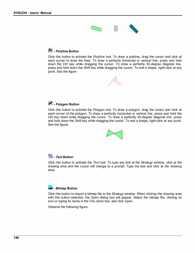
SYSCON - Users’ Manual
146
- Polyline ButtonClick this button to activate the Polyline tool. To draw a polyline, drag the cursor and click ateach corner to draw the lines. To draw a perfectly horizontal or vertical line, press and holddown the Ctrl key while dragging the cursor. To draw a perfectly 45-degree diagonal line,press and hold down the Shift key while dragging the cursor. To end a shape, right-click at anypoint. See the figure:
- Polygon ButtonClick this button to activate the Polygon tool. To draw a polygon, drag the cursor and click ateach corner of the polygon. To draw a perfectly horizontal or vertical line, press and hold theCtrl key down while dragging the cursor. To draw a perfectly 45-degree diagonal line, pressand hold down the Shift key while dragging the cursor. To end a shape, right-click at any point.See the figure:
- Text ButtonClick this button to activate the Text tool. To type any text at the Strategy window, click at thedrawing area and the cursor will change to a prompt. Type the text and click at the drawingarea.
- Bitmap ButtonClick this button to import a bitmap file to the Strategy window. When clicking the drawing areawith this button selected, the Open dialog box will appear. Select the bitmap file, clicking itsicon or typing its name in the File name box, and click Open.
Observe the following figure:
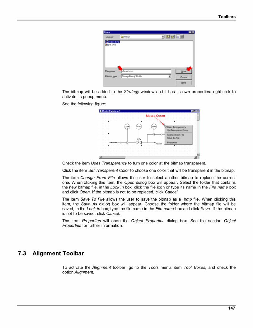
Toolbars
147
The bitmap will be added to the Strategy window and it has its own properties: right-click toactivate its popup menu.
See the following figure:
Mouse Cursor
Check the item Uses Transparency to turn one color at the bitmap transparent.
Click the item Set Transparent Color to choose one color that will be transparent in the bitmap.
The item Change From File allows the user to select another bitmap to replace the currentone. When clicking this item, the Open dialog box will appear. Select the folder that containsthe new bitmap file, in the Look in box; click the file icon or type its name in the File name boxand click Open. If the bitmap is not to be replaced, click Cancel.
The item Save To File allows the user to save the bitmap as a .bmp file. When clicking thisitem, the Save As dialog box will appear. Choose the folder where the bitmap file will besaved, in the Look in box; type the file name in the File name box and click Save. If the bitmapis not to be saved, click Cancel.
The item Properties will open the Object Properties dialog box. See the section ObjectProperties for further information.
7.3 Alignment Toolbar
To activate the Alignment toolbar, go to the Tools menu, item Tool Boxes, and check theoption Alignment.

SYSCON - Users’ Manual
148
Figure 7.5. Tools Menu: Alignment Toolbar
The Alignment toolbar will open:
Figure 7.6. Alignment Toolbar
This toolbar has tools to arrange (or distribute) drawing objects so they are equal distancesfrom each other (vertically or horizontally), or they are aligned by their edges or centers(vertically or horizontally).
- Left Button
Click this button to align the left side of the selected object(s) with the left side of the anchor.
First, select the object (or objects) to be aligned. Then click the button and when the cursor isplaced on the drawing area, it will change to an Indication cursor. Click the object that will bethe anchor. See the figure:
Indication Cursor Aligned Blocks
- Center Button
Click this button to align the horizontal center of the selected object(s) with the horizontalcenter of the anchor.
First, select the object (or objects) to be aligned. Then click the button and when the cursor isplaced on the drawing area, it will change to an Indication cursor. Click the object that will bethe anchor. See the figure:
Indication Cursor Aligned Blocks

Toolbars
149
- Right Button
Click this button to align the right side of the selected object(s) with the right side of theanchor.
First, select the object (or objects) to be aligned. Then click the button and when the cursor isplaced on the drawing area, it will change to an Indication cursor. Click the object that will bethe anchor. See the figure:
Indication Cursor Aligned Blocks
- Top Button
Click this button to align the top of the selected object(s) with the top of the anchor.
First, select the object (or objects) to be aligned. Then click the button and when the cursor isplaced on the drawing area, it will change to an Indication cursor. Click the object that will bethe anchor. See the figure:
Indication Cursor Aligned Blocks
- Middle Button
Click this button to align the vertical center of the selected object(s) with the vertical center ofthe anchor.
First, select the object (or objects) to be aligned. Then click the button and when the cursor isplaced on the drawing area, it will change to an Indication cursor. Click the object that will bethe anchor. See the figure:
Indication Cursor Aligned Blocks

SYSCON - Users’ Manual
150
- Bottom Button
Click this button to align the bottom of the selected object(s) with the bottom of the anchor.
First, select the object (or objects) to be aligned. Then click the button and when the cursor isplaced on the drawing area, it will change to an Indication cursor. Click the object that will bethe anchor. See the figure:
Indication Cursor Aligned Blocks
- Center Points Button
Click this button to align the center of the selected object(s) with the center of the anchor.
First, select the object (or objects) to be aligned. Then click the button and when the cursor isplaced on the drawing area, it will change to an Indication cursor. Click the object that will bethe anchor. See the figure:
Indication Cursor Aligned Blocks
- Evenly Spaced - Horizontal Button
Click this button to distribute the selected objects horizontally, so there is equal horizontaldistance between the edges of all the objects. This button works only for three or moreobjects.
First, select all of the objects to be aligned, and then click the button. The objects will bepromptly aligned. See the figure:
Aligned BlocksSelected Blocks
- Evenly Spaced - Vertical Button
Click this button to distribute the selected objects vertically, so there is equal vertical distancebetween the edges of all the objects. This button works only for three or more objects.

Toolbars
151
First, select all of the objects to be aligned, and then click the button. The objects will bepromptly aligned. See the figure:
Aligned BlocksSelected Blocks
7.4 Ordering Toolbar
To activate the Ordering toolbar, go to the Tools menu, item Tool Boxes, and check the optionOrdering.
Figure 7.7. Tools Menu: Ordering Toolbar
The Ordering toolbar will open:
Figure 7.8. Ordering Toolbar
This toolbar has tools to overlap as many drawing objects as desired and rearrange them inthe stack.
- To Front Button
Click this button to place the selected object in front of other overlapping objects. Select theobject to be moved and click the button. See the figure:
Selected Object After Ordering

SYSCON - Users’ Manual
152
- To Back Button
Click this button to place the selected object behind other overlapping objects. Select theobject to be moved and click the button. See the figure:
Selected Object After Ordering
- Forward One Button
Click this button to move the selected object one position forward in the stacking order. Selectthe object to be moved and click the button. See the figure:
Selected Object After Ordering
- Backward One Button
Click this button to move the selected object one position backward in the stacking order.Select the object to be moved and click the button. See the figure:
Selected Object After Ordering
- Reverse Order Button
Click this button to reverse the stacking order of two selected objects. To select two objects,click the first object. Hold the key Shift pressed and click the second object. Click the buttonand the stacking order will be reversed. See the figure:

Toolbars
153
Selected Objects After Ordering
- In Front Of Button
Click this button to place the selected object in front of another object that will be the anchor.Select the object to be moved and click the button. When the cursor is placed in the drawingarea, it will change to an Indication cursor with a plus sign, +. Click on the anchor object toconclude this task. See the figure:
Selected Object After Ordering
+
IndicationCursor
- Behind Button
Click this button to place the selected object behind another object that will be the anchor.Select the object to be moved and click the button. When the cursor is placed in the drawingarea, it will change to an Indication cursor with a minus sign, -. Click on the anchor object toconclude this task. See the figure:
Selected Object After Ordering
-
IndicationCursor
7.5 Copy Attributes Toolbar
To activate the Copy Attributes toolbar, go to the Tools menu, item Tool Boxes, and check theoption Copy Attributes.

SYSCON - Users’ Manual
154
Figure 7.9. Tools Menu: Copy Attributes Toolbar
The Copy Attributes toolbar will open:
Figure 7.10. Copy Attributes Toolbar
This toolbar has tools that make an object(s) appearance equal to another object.
- Same Width Button
Click this button to copy the width from one object to another. Select the object that will haveits width changed, and click the button. The cursor will change to an Indication cursor. Clickthe anchor object to copy its width and conclude this task. See the figure:
After Copying WidthIndication Cursor
- Same Height Button
Click this button to copy the height from one object to another. Select the object that will haveits height changed, and click the button. The cursor will change to an Indication cursor. Clickthe anchor object to copy its height and conclude this task. See the figure:
After Copying HeightIndication Cursor

Toolbars
155
- Same Dimensions Button
Click this button to copy the width and the height from one object to another. Select the objectthat will have its dimensions changed, and click the button. The cursor will change to anIndication cursor. Click the anchor object to copy its dimensions and conclude this task. Seethe figure:
After Copying DimensionsIndication Cursor
- Same Pen & Brush Button
Click this button to copy the line and the fill color from one object to another. Select the objectthat will have its colors changed, and click the button. The cursor will change to an Indicationcursor. Click the anchor object to copy its colors and conclude this task. See the figure:
After Copying Line andFill Colors
Indication Cursor
- Same Font & Colors Button
Click this button to copy the text font and colors from one object to another. Select the objectthat will have its font and color changed, and click the button. The cursor will change to anIndication cursor. Click the anchor object to copy its colors and conclude this task. See thefigure:
After Copying Text Fontand ColorsIndication Cursor
- Same Text Attributes Button
Click this button to copy the text font, size and colors, from one object to another. Select theobject that will have its text attributes changed, and click the button. The cursor will change toan Indication cursor. Click the anchor object to copy its colors and conclude this task. See thefigure:

SYSCON - Users’ Manual
156
After Copying TextAttributesIndication Cursor
- Set Attributes As Default Ones Button
Click this button to set the objects attributes as default. Select the object that will have itsattributes set as default and click the button. The objects will be drawn with the same linecolor, fill color, text font and text size as the object selected.
7.6 Topology Toolbar
The Topology toolbar is activated with the Fieldbus Networks window. In case it’s notactivated, go to the Tools menu, item Tool Boxes, and the option Topology should be checked.
Figure 7.11. Tools Menu: Topology Toolbar
The Topology toolbar will open:
Figure 7.12. Topology Toolbar
- Select Button
Click this button to activate the Select tool. With this button selected, it is possible to select anyobject(s) at the Fieldbus Networks window for further operations, such as moving, resizing etc.

Toolbars
157
- Topology Modify ButtonClick this button to activate the Modify tool. This tool is used to change an object’s shape.
Use this tool to redraw Links: when the user selects a Link, the Modifying Corners appears.Drag them onto the drawing area to redraw the Link.
- Dummy Bridge ButtonClick this button to create new Bridges. Click the drawing area with this button selected andthe New Bridge dialog box will open.
Select the Bridge Manufacturer and Type, clicking the down arrows, and type the Bridge tag.The Bridge will be drawn after clicking Ok.
- Fieldbus ButtonClick this button to create a new Fieldbus. Click the drawing area with this button selected andthe New Fieldbus dialog box will open.
Select the communication port for the Fieldbus and type the tag. The Fieldbus will be drawnafter clicking Ok.

SYSCON - Users’ Manual
158
- Topology Link ButtonClick this button to create Links between a Fieldbus and a Bridge. Click the Bridge, select theport, and then click the Fieldbus. The Link will be drawn.
7.7 Characterization Toolbar
The Characterization toolbar is displayed in the Block Characterization dialog box.
Figure 7.13. Characterization Toolbar
- Input Button
Click this button to display the Input Parameters of the Block. An Input Parameter obtains itsvalue from a source external to the Block.
- Output Button
Click this button to display the Output Parameters of the Block. An Output Parameter is aParameter that may be linked to an Input Parameter of another Function Block.
- Contained ButtonClick this button to display the Contained Parameters of the Block. A Contained Parameter is aParameter whose value is configured, set by an operator, higher-level device or calculated.
- Dynamic ButtonClick this button to display the Dynamic Parameters of the Block. Dynamic Parameter valuesare calculated by the Block algorithm and therefore do not need to be restored after a powerfailure.
- Diagnostic ButtonClick this button to display the Diagnostic Parameters of the Block.

Toolbars
159
- Service ButtonClick this button to display the Service Parameters of the Block.
- Operate ButtonClick this button to display the Operate Parameters of the Block.
- Alarm Button
Click this button to display the Alarm Parameters of the Block. Alarms and events, known asalerts, represent state changes within Function Block applications.
- Tune ButtonClick this button to display the Tune Parameters of the Block.
- Local ButtonClick this button to display the Local Parameters of the Block.
- Confirmed Edition ButtonIf this button is highlighted, the user will change the Parameter value then click the End Editbutton at the bottom of the Characterization window, or press the Enter key on the keyboard,to confirm the edition and accept the changes.
If this button is not highlighted, the user will change the Parameter value then click the EndEdit button at the bottom of the Characterization window, press the Enter key on the keyboard,or click on another Parameter line, to confirm the edition and accept the changes.
- Column Relative Index ButtonClick this button to display the Relative Index column.
- Column Handling ButtonClick this button to display the Handling column.
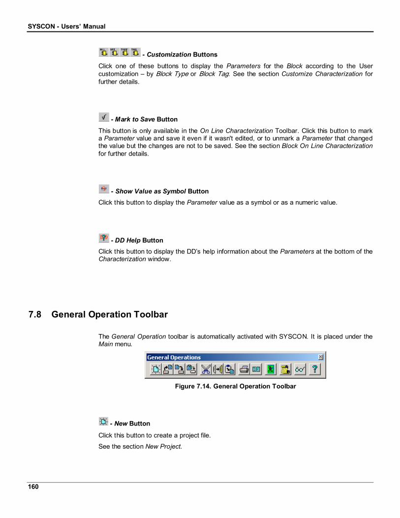
SYSCON - Users’ Manual
160
- Customization Buttons
Click one of these buttons to display the Parameters for the Block according to the Usercustomization – by Block Type or Block Tag. See the section Customize Characterization forfurther details.
- Mark to Save Button
This button is only available in the On Line Characterization Toolbar. Click this button to marka Parameter value and save it even if it wasn't edited, or to unmark a Parameter that changedthe value but the changes are not to be saved. See the section Block On Line Characterizationfor further details.
- Show Value as Symbol ButtonClick this button to display the Parameter value as a symbol or as a numeric value.
- DD Help ButtonClick this button to display the DD’s help information about the Parameters at the bottom of theCharacterization window.
7.8 General Operation Toolbar
The General Operation toolbar is automatically activated with SYSCON. It is placed under theMain menu.
Figure 7.14. General Operation Toolbar
- New Button
Click this button to create a project file.
See the section New Project.

Toolbars
161
- Open ButtonClick this button to open a project file. See the section Open.
- Save ButtonClick this button to save the project or any of its parts, such as the Process Cell window or theStrategy window. See the section Save.
- Save All ButtonClick this button to save the entire plant project configuration. See the section Save EntireConfiguration.
- Cut Button
Click this button to remove the selection from the project and place it on the clipboard.
- Copy Button
Click this button to copy the selection to the clipboard.
- Paste Button
Click this button to insert the contents of the clipboard at the insertion point. This command isavailable only if the user has cut or copied an object.
- Print ButtonClick this button to print the project configuration, or the drawing objects at the Strategywindow, or the drawing objects at the Topology window. See the section Printing the ProjectConfiguration.
- Print Preview Button
Click this button to see how the project will be printed. The user can change the printerconfiguration and select the objects to be printed. See the section Print Preview.

SYSCON - Users’ Manual
162
- Operation Mode Button
Click this button to toggle between the Operation Modes. If the button is clicked, SYSCON isoperating in the On Line mode. Otherwise, it’s in the Off Line mode.
- Error Log ButtonClick this button to open the Error Log window. This button will be activated if there was anerror during a communication procedure.
- Show/Hide ButtonClick this button to show or hide detailed information about Blocks types, Blocks Parameters,Devices types and Fieldbus MacroCycle.
- Contents Button
Click this button to open the SYSCON Help Contents.

Device Support
163
8 Device Support
8.1 Including New DD and Capabilities File
The Device Description for a particular Device is provided by the Device‘s manufacturer anddistributed by Fieldbus Foundation. If it is not currently available from the Fieldbus Foundation,the user may need to contact the manufacturer and get a copy of the DD.
There is a DD for each Device type, and it consists of the files whose extensions are “.ffo” and“.sym”.
The Capabilities File is used to define the Device capabilities – e.g., dynamic blockinstantiation capability - and the resources available for creating Function Block Applications,Resource Blocks, Transducer Blocks, and Function Blocks.
There is a Capabilities File for each Device type. It consists of the files where the extensionsare “.cff”, and then are placed together with the DD files.
The files are organized in the manufacturers’ folder as the following figure shows:
SYSCON needs DD and Capabilities Files in order to configure a Device.
Follow the steps below to add a new DD and Capabilities File to SYSCON:
1. Go to the Device Support installation folder.
2. Inside the Device Support folder, create a new folder for the manufacturer, if it is notyet there.
3. The folder name should be a 6 hexadecimal digits manufacturer’s code, e.g., 000302for SMAR.
4. Inside the manufacturer’s folder, create the Device Type folder.
5. The name for this folder should be the 4 hexadecimal digits of the Device Type code,e.g., 0001 for the LD302.
6. Copy the DD and the Capabilities Files for the new Device from the correspondingfolder to the newly created manufacturer and Device Type folders, inside the DeviceSupport folder.

SYSCON - Users’ Manual
164
After that, SYSCON will be able to reference the new DDs in the dialog boxes for creation ofDevices and Blocks, showing the Manufacturer ID and the Device Type code.
However, SYSCON will not be able to show the manufacturer name or the Device name. Toshow those names on SYSCON, the user must define them in the “Device Support.ini“ file.See the section Defining Manufacturers and Device names.
If the Device supports dynamic instantiation of Function Blocks, the user must define theFunction Block Mnemonics. See the section Defining a Block Mnemonic.
If the Capabilities File is not provided, the user can define it since the necessary information isavailable. See the section Creating a new Capabilities File.
8.2 Defining Manufacturers and Device Names
The file “Device Support.ini” in the folder Device Support maintains all definitions for themanufacturers’ and Devices’ names. The user may need to add definitions.
SYSCON gives the user the opportunity to define manufacturers’ and Devices’ names in orderto show them in the dialog boxes when adding new Devices or new Blocks to the FieldbusConfiguration.
Follow the steps below to add new definitions:
1. Open the “Device Support.ini” file.
2. Create the new manufacturer in the [Manufacturers By Id] section.
The definition of the name for a particular manufacturer has the following format:
<manufacturer_id> = <manufacturer_name>
where
“manufacturer_id“ is the 6 hexadecimal digits manufacturer’s code;
“manufacturer_name“ is the manufacturer’s name that will appear in the dialogboxes.
Example:
[Manufacturers By Id]
000302=Smar
3. Create a section to maintain the new manufacturer’s Devices.
The definition of the section for a particular manufacturer has the following format:[<manufacturer_id> Devices By Code]
where
“manufacturer_id“ is the 6 hexadecimal digits manufacturer’s code.

Device Support
165
Example:
[000302 Devices By Code]
4. Define the Devices’ names in this new section.
The definition of the name for a particular Device has the following format:
<device_type_code>=<device_name>
where
“device_type_code“ is the 4 hexadecimal digits of the Device Type code;
“device_name” is the Device’s name that will appear in the dialog boxes.
Example:0001=LD 302
8.3 Creating a new Capabilities File
If the Capabilities File is not provided, it can still be defined since the user already has thenecessary information.
The source of information may be the Device Manufacturer, the Device itself or the old “.ini “or “.drf “ Resource Files.
Follow these steps to define a Capabilities File:
1. Copy the template file “Capabilities.cff” at the SYSCON folder.
2. Go to the Device Support installation folder and paste it in the Device foldercorresponding to the Device being created in the Capabilities File.
3. Rename the file to match the corresponding DD files.
4. Edit the template file and provide all of the necessary information.
5. If the Device supports dynamic instantiation of Function Blocks, the Function BlockMnemonics will still have to be defined in the file “Device Support.ini”.
If there is any Block Mnemonic missing, then add its definition to the “Device Support.ini” file.See the section Defining a Block Mnemonic.
8.4 Defining a Block Mnemonic
When defining a Capabilities File for a Device that can dynamically create instances ofFunction Blocks, the user must create a section for each one of these Blocks in the “.cff “ file.
The Function Block Mnemonic names those sections. Therefore, the user should define eachof the Function Blocks Mnemonics, so that SYSCON can identify the Blocks.
SYSCON - Users’ Manual
166
Blocks Mnemonics are defined in the file “Device Support.ini”, located in the Device Supportfolder, in a section named “[Block Type Mnemonics]”.
Inside this section, the definition of the Mnemonic for a particular Function Block has thefollowing format:
[Block Type Mnemonics]
<m_id> <d_type> <d_revision> <dd_revision><block_dditemid>=<block_mnemonic>
where:
<m_id> is the 6 hexadecimal digits manufacturer’s code;
<d_type> is the 4 hexadecimal digits of the Device Type;
<d_revision> is the Device Revision;
<dd_revision> is the DD Revision;
<block_dditemid> is the DDItemId;
<block_mnemonic> is the mnemonic for the Block.
Example:
[Block Type Mnemonics]
000302 0001 01 02 800202B0=PID
where:
000302 is the SMAR manufacturer code;
0001 is LD302 Device Type code;
01 is the Device Revision;
02 is the DD Revision;
800202B0 is the DDItemId for the Block PID.
Just follow this pattern to add new definitions.

Troubleshoot
167
9 Troubleshoot1. Version Mismatch
Converting from an older configuration version.For discarding, close without saving.
This is a message, not an exception. It means that the user is trying to open a configurationfile, which was generated in an older version of the tool that had an old-fashioned file format. Ifthe user accepts to upgrade, the configuration is going to be converted to the new file formatand the user won't be able to open the configuration in a version of the tool, which supportsthe old file format again. This message is only issued by SYSCON from version 5.10 on.
2. Version MismatchUnable to open a newer configuration version.
This is a message, not an exception. It means that the user is trying to open a configurationfile, which was generated in an earlier version of the tool that has a new file format. SYSCONcannot perform configuration downgrade. This message is only issued by SYSCON fromversion 5.10 on.
3. DD ExceptionStandard Dictionary Not Found!
This means that the Standard.dct file is missing in the Device Support and can generallyhappen because of problems during the system installation.
4. FF ExceptionBlock with Profile 0x#### and Profile Revision 0x#### could not be found.DD and CF: ######\####\####(##).DDItem = 0x########
This happens because some block type could not be recognized. It means there wereproblems with DDs or CFs installation. During the opening of a configuration file it has aspecial meaning, and it can easily be identified by the null Profile and Profile Revisionnumbers. In this case SYSCON is trying to upgrade a configuration generated with an oldversion of SYSCON (4.x or earlier) that didn't work - therefore did not retain the numbers.During the configuration file upgrade, SYSCON tries to get the Profile and Profile Revision forthe blocks in the configuration by searching the CF given the DDItemID for the block. This FFexception occurs because the CF is not present or, in case the CF exists, the exception occursbecause the CF might be inconsistent. It is very common when a configuration is generated inone machine and moved to another one that maintains a different set of DDs and CFs from theoriginal machine. The DD and CF information in the message identifies which CF file has beensearched.

SYSCON - Users’ Manual
168
5. Maximum number of Blocks has been exceeded.License Violation
It means that the user is trying to open a configuration that has more blocks than the SYSCONlicense allows. This usually happens when the project file has been generated with a SYSCONversion that supports the number of blocks configured in the project, but the user is trying toopen the project with another SYSCON version with a license that allows less blocks than hasbeen configured in the project file.
6. DD Not Found
If SYSCON tries to use a DD file that is missing or corrupted, the Device Description Errormessage will be sent to the user through the Error Log window. This message indicates theDD file that is missing or corrupted and reports the details about the error.
There is one situation that a missing DD will stop the application. When a configuration file isgenerated with SYSCON version 4.x, or previous versions, and the user attempts to open thefile with SYSCON version 5.22, the application will generate an exception indicating theinformation that is missing and will abort after the user acknowledgement.
7. The HSE port of the DFI has address 0
This problem may occur when:
The address wasn’t read because the Bridge was not found in the Live List.
The Bridge was not in the Live List during the Init Communication.
These conditions mean that the problem occurs rarely. If it occurs, it will be necessary toterminate the communication and restart it.
8. Multilink Topology Request
This dialog box will open when SYSCON tries to re-initialize the communication after an eventoccurs, for example, when the Bridge stop communicating for a moment and then return tonormal operation.

Appendix
169
Appendix: Step-by-Step Configuration
The first example starts the configuration from the Logical Project.
The second example starts the configuration from the Physical Project.
It is recommended that the user start with the Logical Project Configuration and then importTemplates files to the Strategy window. This way the user can easily add Blocks to the projectto be more productive.
In this Fieldbus configuration example, the Analog Input, the PID Control and the AnalogOutput Blocks will be used to build the following Cascade Control configuration:

SYSCON - Users’ Manual
170
Creating the Project File
To create a new Fieldbus project, click the New button, , on the General Operation toolbar.
The Document Type box will appear. Click the option Projects, as indicated below:
The New Project dialog box will open:
Type the name for the new project at the File Name box, and then click Save. The Projectwindow will open.
Starting with the Process Control Configuration
At the Project window, right-click the Area1 icon and click the item New Process Cell. TheProcess Cell dialog box will open.

Appendix
171
Type the Process Cell tag and click Ok.
Double-click the Process Cell icon to open its own window. To organize the screen view, go tothe Window menu and click Tile.
Now add the Control Module. Select the Process Cell icon, on the Process Cell window, andright-click it. Click the item New Control Module. The Control Module dialog box will open.
Type the Control Module tag and click OK.
Adding Blocks
Now add the Blocks that will be used at the design configuration.
Right-click the Control Module icon and select the item New Block. The New Block dialog boxwill open:
1. Select Smar in the Manufacturer box.
2. Select the TT302 Device in the Device Type box.
3. Select Analog Input in the Block Type box.
4. Type the tag TT100, or any other related tag, in the Block Tag box.
5. Click OK.
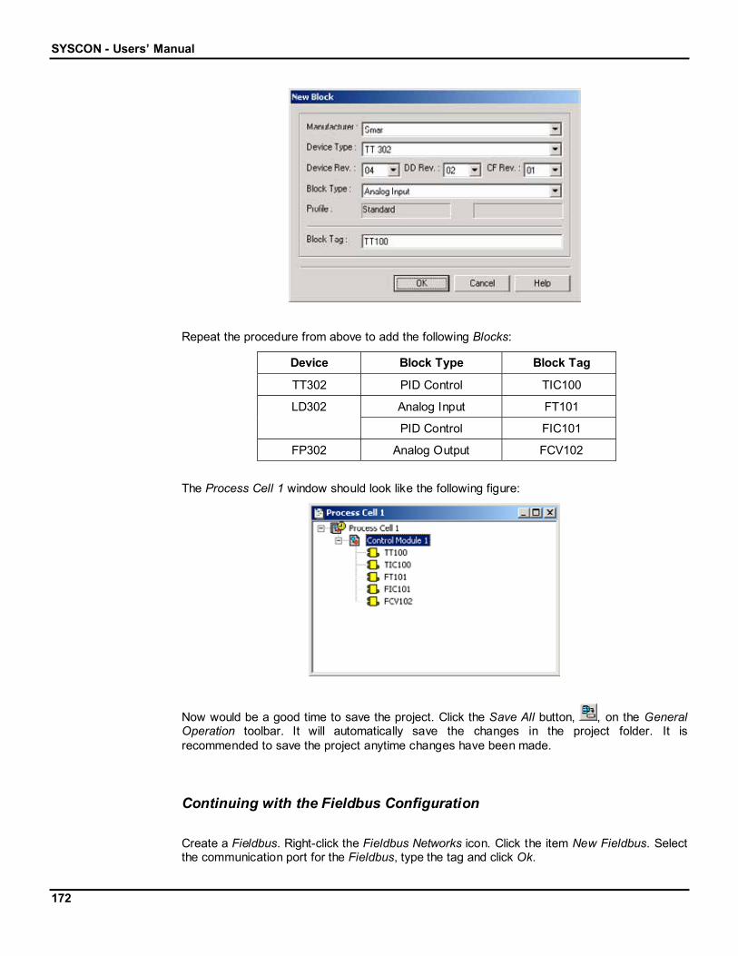
SYSCON - Users’ Manual
172
Repeat the procedure from above to add the following Blocks:
Device Block Type Block Tag
TT302 PID Control TIC100
Analog Input FT101LD302
PID Control FIC101
FP302 Analog Output FCV102
The Process Cell 1 window should look like the following figure:
Now would be a good time to save the project. Click the Save All button, , on the GeneralOperation toolbar. It will automatically save the changes in the project folder. It isrecommended to save the project anytime changes have been made.
Continuing with the Fieldbus Configuration
Create a Fieldbus. Right-click the Fieldbus Networks icon. Click the item New Fieldbus. Selectthe communication port for the Fieldbus, type the tag and click Ok.

Appendix
173
Double-click the Fieldbus icon to open its window.
To add the Devices, select the Fieldbus icon, on the Fieldbus window, and right-click it. Clickthe item New Device.
First, add the Smar Temperature Transmitter – TT302.
1. Select Smar in the Device Manufacture box.
2. Select the TT302 Device in the Device Type box.
3. Type the tag Temperature, or any other related tag, in the Device Tag box.
4. Click OK.
Follow the same procedure to add the Smar Flow Transmitter – LD302, and the Smar FlowValve Controller – FP302.
The next step will be to attach the Blocks, from the Control Module to the Devices.
Open the Fieldbus window and the Process Cell window. Arrange these windows side by sideby clicking the item Tile at the Window menu.
At the Process Cell window, click on the Block that will be attached and drag it to thecorresponding Device, at the Fieldbus window.
Selected Block
The Block will be attached to the Device.
Repeat this operation to attach all Blocks to the Devices, according to the table below:
Device Block Tag
TT100Temperature
TIC100
FT101Flow
FIC101
Flow Valve FCV102
When all of the blocks are attached, the user will have to drag the Blocks to the Strategywindow to start the design configuration.

SYSCON - Users’ Manual
174
Starting with the Fieldbus Configuration
At the Project window, right-click the Fieldbus Networks icon and click the item New Fieldbus.The New Fieldbus dialog box will open. Select the communication port for the Fieldbus, typethe tag and click Ok.
Double-click the Fieldbus 1 icon to open its window. To organize the screen view, go to theWindow menu and click Tile.
Now add the Devices that will be used in this project.
First, add the Smar Temperature Transmitter – TT302.
At the Fieldbus 1 window, right-click the Fieldbus1 icon, then click the item New Device. TheDevice dialog box will open:
1. Select Smar in the Device Manufacture box.
2. Select the TT302 Device in the Device Type box.
3. Type the tag Temperature, or any other related tag, in the Device Tag box.
4. Click OK.
Follow the same procedure to add the Smar Flow Transmitter – LD302, and the Smar FlowValve Controller – FP302.
After finishing this process, the Fieldbus 1 window should look like the following figure:

Appendix
175
Adding Blocks
Now add the Blocks that will be used at the design configuration.
To add a new Block, click the Device expansion sign, , select the FB icon and right-click it.Click the item New Block.
The New Block dialog box will open. Add the first Block:
1. Select Analog Input in the Block Type box.
2. Type the tag TT100, or any other related tag, in the Block Tag box.
3. Click OK.
Repeat the procedure from above to add the following Blocks:
Device Block Type Block Tag
Temperature PID Control TIC100
Analog Input FT101Flow
PID Control FIC101
Flow Valve Analog Output FCV102
The Fieldbus window should look like the following figure:

SYSCON - Users’ Manual
176
Remember to save the project.
Continuing with the Process Control Configuration
Create a Process Cell. Right-click the Area icon. Click the item New Process Cell. Type theProcess Cell tag and click OK.
Double-click the Process Cell 1 icon to open the window.
To create a Control Module select the Process Cell icon, on the Process Cell window, andright-click it. Click the item New Control Module. Type the Control Module tag and click OK.
The next step will be to attach the Blocks, from the Devices to the Control Module.
Open the Fieldbus window and the Process Cell window. Arrange these windows side by sideby clicking the item Tile at the Window menu.
At the Fieldbus window, click on the Block that will be attached and drag it to the Process Cellwindow, on the Control Module icon.
The Block will be attached to the Control Module.
Repeat this operation to attach all Blocks to the Control Module.
When all of the blocks are attached, the user will have to drag the Blocks to the Strategywindow to start the design configuration.
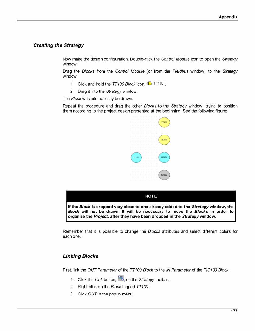
Appendix
177
Creating the Strategy
Now make the design configuration. Double-click the Control Module icon to open the Strategywindow.
Drag the Blocks from the Control Module (or from the Fieldbus window) to the Strategywindow:
1. Click and hold the TT100 Block icon, .
2. Drag it into the Strategy window.
The Block will automatically be drawn.
Repeat the procedure and drag the other Blocks to the Strategy window, trying to positionthem according to the project design presented at the beginning. See the following figure:
NOTE
If the Block is dropped very close to one already added to the Strategy window, theBlock will not be drawn. It will be necessary to move the Blocks in order toorganize the Project, after they have been dropped in the Strategy window.
Remember that it is possible to change the Blocks attributes and select different colors foreach one.
Linking Blocks
First, link the OUT Parameter of the TT100 Block to the IN Parameter of the TIC100 Block:
1. Click the Link button, , on the Strategy toolbar.
2. Right-click on the Block tagged TT100.
3. Click OUT in the popup menu.

SYSCON - Users’ Manual
178
4. Drag the cursor to the Block tagged TIC100.
5. Right-click on the Block.
6. Select IN from the Parameters List.
The linking process is complete.
Follow the steps above to link the OUT Parameter of the TIC100 Block to the CAS_INParameter of the FIC101 Block.

Appendix
179
Repeat the process and link the OUT Parameter of the FT101 Block to the IN Parameter of theFIC101 Block.
Then, link the OUT Parameter of the FIC101 Block to the CAS_IN Parameter of the FCV102Block. The Strategy window should look like the following figure:
To create the Feedback Link between FIC101 and TIC100, follow these steps:
1. Right-click on the FIC101 Block.
2. Select BKCAL_OUT from the Parameters List.
3. Drag the cursor diagonally to the left side of the middle.
4. Click on the drawing area.
5. Continue dragging the cursor vertically until the Link line is near the TIC100 Block.
6. Click on the drawing area.
7. Drag the Link line horizontally until it reaches the TIC100 Block.

SYSCON - Users’ Manual
180
ModifyingHandles
Mouse Cursor
To conclude the Link:
8. Right-click on the TIC100 Block.
9. Select BKCAL_IN from the Parameters List.
The design configuration should look like the following figure:
Follow these steps above to link the BKCAL_OUT Parameter of the FCV102 Block to theBKCAL_IN Parameter of the FIC101 Block.
At the end of the linking process, the Strategy window should look like the following figure:
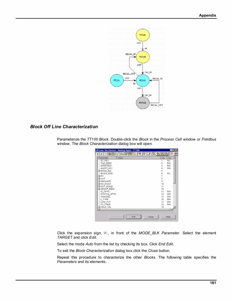
Appendix
181
Block Off Line Characterization
Parameterize the TT100 Block. Double-click the Block in the Process Cell window or Fieldbuswindow. The Block Characterization dialog box will open:
Click the expansion sign, , in front of the MODE_BLK Parameter. Select the elementTARGET and click Edit.
Select the mode Auto from the list by checking its box. Click End Edit.
To exit the Block Characterization dialog box click the Close button.
Repeat this procedure to characterize the other Blocks. The following table specifies theParameters and its elements:

SYSCON - Users’ Manual
182
Block Parameter Element Mode
MODE_BLK TARGET Auto
EU_100 600
EU_0 0PV_SCALE
UNITS_INDEX °C
EU_100 200
EU_0 0
TIC100
OUT_SCALE
UNITS_INDEX kg/h
MODE_BLK TARGET Auto
EU_100 200
EU_0 0XD_SCALE
UNITS_INDEX inH2O
EU_100 200
EU_0 0OUT_SCALE
UNITS_INDEX kg/h
FT-101
L_TYPE Indirect Sq Root
MODE_BLK TARGET Cas
EU_100 200
EU_0 0PV_SCALE
UNITS_INDEX kg/h
EU_100 100
EU_0 0
FIC-101
OUT_SCALE
UNITS_INDEX %
MODE_BLK TARGET Cas
EU_100 100
EU_0 0PV_SCALE
UNITS_INDEX %
EU_100 15
EU_0 3
FCV-102
XD_SCALE
UNITS_INDEX psi
It would be a good idea to save the project file before continuing with the configuration.