Embed Size (px)
Citation preview

Published in: Stahlbau, Volume 85, Issue 9 (9/2016). Copyright © 2016 Ernst & Sohn Verlag für Architektur und technische Wissenschaften GmbH & Co. KG, Berlin
Structural design of offshore wind turbine support structures is a complex process, which has many challenges. In
particular in the early phase of a project it is difficult to select the appropriate structural concept and to determine
structural masses with reasonable accuracy, without having to go through a time-consuming iterative process. In the
more advanced stages, care must be taken that required data for an optimized design has been collected earlier and
that the right software tools are available such that all parties involved can execute the design work. In this paper,
practical advice is given how this process can be organized and which methods can be used. Furthermore, common
mistakes are highlighted, such that those can be avoided.
Entwurfsprozess für Tragstrukturen von Offshore-Windenergieanlagen – Praktische Vorgehensweisen und
Fallstricke während unterschiedlicher Phasen. Der Entwurf von Tragstrukturen für Offshore-Windenergieanlagen
ist eine anspruchsvolle Aufgabe. Insbesondere in der frühen Entwurfsphase ist es oft schwierig, die richtige Ent-
scheidung für das Konzept der Tragstruktur zu treffen und die strukturellen Massen mit angemessener Genauigkeit
zu bestimmen, da dies häufig in einem zeitaufwendigen Iterationsprozess mündet. Im weiteren Verlauf muss sicher-
gestellt sein, dass alle notwendigen Eingangsdaten für ein optimiertes Design vorliegen und die beteiligten Parteien
über die notwendige Software verfügen. In dieser Veröffentlichung werden praktische Hinweise gegeben, wie dieser
Prozess durchgeführt werden kann und welche Methoden in welcher Phase angemessen sind. Außerdem werden
häufige Fehler beschrieben, damit diese vermieden werden können.
Keywords: Offshore wind turbine, Monopile, Jacket, Design process, Fatigue design, Offshore-WEA, Entwurf-
sprozess, Ermüdung
Published in: Stahlbau, Volume 85, Issue 9 (9/2016). Copyright © 2016 Ernst & Sohn Verlag für Architektur und
technische Wissenschaften GmbH & Co. KG, Berlin
Marc Seidel
Sven Voormeeren
Jan-Bart van der Steen
State-of-the-art design processes for offshore
wind turbine support structures
Practical approaches and pitfalls during different stages in the design process

Published in: Stahlbau, Volume 85, Issue 9 (9/2016). Copyright © 2016 Ernst & Sohn Verlag für Architektur und technische Wissenschaften GmbH & Co. KG, Berlin
1 Introduction
As projects go through different phases, support structure designs with varying levels of detail are re-
quired. In the initial stages, the support structure concept needs to be developed and overall mass is of
interest. This is typically achieved with simplified methods and for selected positions of a wind farm
only. Towards the final design, the design and masses are refined and transferred to all individual posi-
tions. Approaches suitable for each phase, for both monopiles and jackets, are summarized graphically in
Fig. 1 and described in Table 1.
Bild 1. Flussdiagramm für die Entwicklungsstufen
Fig. 1. Flow-chart summarizing different phases
Tabelle 1. Beschreibung der Entwicklungsstufen
Table 1. Description of design phases
Stage Description
Conceptual
Design
Determination of the initial support structure dimensions such as pile diameters, wall thicknesses and pile
length. Conceptual layout of secondary structures needs to be defined for the load calculations (e.g. boat
landing orientation). Purpose is to define a suitable support structure for the site, provide input to financial
models and to define a starting point for detailed load simulations.
Basic
Design
Basic design of the support structure for the selected load-design positions in the wind farm, based on detailed
time domain load simulations. Basic design is performed in an iterative process between load calculations and
structural design; typically 2-3 iterations are performed. Purpose is to obtain well-defined structures for at least
the extreme positions and often a few additional representative positions in the wind farm. Overall steel mass
can be estimated based on this.
Detailed
Design
Detailed design for all positions within the wind farm, using interpolated loads from the load-design positions.
This allows position specific optimization of the primary structure. Furthermore, all other design items (e.g.
secondary structures, corrosion protection) are finalized at this stage.

Published in: Stahlbau, Volume 85, Issue 9 (9/2016). Copyright © 2016 Ernst & Sohn Verlag für Architektur und technische Wissenschaften GmbH & Co. KG, Berlin
2 Design approaches for Monopiles
Monopile and Transition Piece dimensions are dominated by wave induced fatigue loads for the current
turbine size of 6-8MW and water depths typically in the range of 20-40m. Only parts of the design are
driven by extreme loads, this typically applies to the tower top region, flanges and other connections
(grouted joints) and the pile embedment length. As “wind only loads” are fairly well and easily predicta-
ble based on the wind conditions at site, the main effort is on wave induced loads.
2.1 Design Basis
The Design Basis should thoroughly cover met-ocean conditions; in particular the following should be
included:
For calculation of FLS (Fatigue Limit State) design load cases:
Omnidirectional scatter tables for VHub-HS and HS-TP for initial design stages (VHub: Wind
speed at hub height, HS: Significant wave height, TP: Peak period).
Full directional information on wave conditions as a function of wind speed and wind direc-
tion, i.e. HS-TP-scatter diagrams for 12 wind directions (30° intervals), 12 wave directions and
~35 wind speeds (up to ~35m/s in 1m/s intervals). This results in ~5040 scatter tables. Oppo-
site directions can be added, reducing the number of wind and wave directions to 6 each, re-
sulting in ~1260 scatter tables in total.
For calculation of ULS (Ultimate Limit State) design load cases:
Extreme sea states (ESS) and extreme wave heights (EWH) should also be included for 12 di-
rections. This is beneficial, as appurtenances like boat landings can increase wave loads signif-
icantly and taking into account their locations vs. directional wave heights reduces extreme
loads.
In cases where wave breaking might occur, extreme sea states should be specified conditional
on direction and water level. For sites with relatively shallow water, the lowest water level of-
ten drives extreme wave loads.
2.2 Conceptual Design
2.2.1 General remarks
For the conceptual design, the initial question is about feasibility of the monopile, considering current
weight limits for fabrication and installation. In order to arrive at a reasonable estimate of fatigue (FLS)
and extreme (ULS) loads, the following steps need to be completed:
1) Firstly, it is extremely important to realize that the wind turbine manufacturer cannot a priori
deliver any sensible “generic loads” which are combined wind-wave loads applicable to the
site. In particular fatigue loads are too dependent on site conditions. Any combined wind-wave
load set which does not take soil and wave conditions from the site into account can thus only
be termed “arbitrary” loads and any reasonable design process must involve calculation of site
specific combined wind and wave loads.
2) The most important input for support structure load calculations concerns soil stiffness / soil-
structure-interaction. It is therefore not a good approach to start with conservative values of
soil strength parameters and stiffness models. Such conservatism can lead to unrealistically
high support structure masses, resulting in incorrect conclusions about monopile feasibility /
economics. It is therefore important to apply state-of-the-art methods for soil-structure-
interaction, see e.g. Versteijlen et al. [1].

Published in: Stahlbau, Volume 85, Issue 9 (9/2016). Copyright © 2016 Ernst & Sohn Verlag für Architektur und technische Wissenschaften GmbH & Co. KG, Berlin
3) If monopile feasibility is deemed to be on the verge, minimizing hub height is one of the im-
portant levers to limit masses.
2.2.2 First steps of the design process
To initiate the design, a starting point is needed. This is done with the following steps.
4) Based on experience, a first support structure geometry is created.
5) The first natural frequency of wind turbine and support structure is calculated and compared
with the allowable frequency band (given by the turbine manufacturer, e.g. to avoid resonance
with the blade passing frequency). Furthermore, modal damping for the first fundamental
eigenmode is calculated / estimated. If passive damping devices are used, their damping con-
tribution is also determined.
6) FLS and ULS loads are then estimated as described in the following and used for refinement of
the structure.
During this stage, no load simulations in the time domain are required.
2.2.3 Estimation of fatigue loads (FLS loads)
The initial structure is used in the following to estimate fatigue loads (FLS loads). Those are at this stage
presented as “Damage equivalent loads” (DELs), i.e. load spectra with one load range only.
7) Wind turbine manufacturer (WTM) provides “wind only” loads, based on hub height, wind
conditions and natural frequency. It is important to note that such loads are not very sensitive
to natural frequency, unlike wave induced loads.
8) Furthermore, WTM needs to provide information on fore-aft and side-side aerodynamic damp-
ing during production and idling. This can be done in a simplified manner, lumped over all
wind speeds and directions, or in a more sophisticated way (e.g. dependent on wind speed and
direction).
9) As idling conditions typically result in the highest loads for the support structure, the technical
availability of the wind turbine needs to be agreed upon.
Foundation designer (FD) needs to calculate wave induced fatigue loads. This can be done by time do-
main simulations, but this is time consuming. It is much more practical, yet still very accurate, to use
frequency domain methods to determine wave induced fatigue loads. Depending on available tools,
simplified approaches as described by Seidel [2] or full frequency domain calculations can be used. At
this stage, the omnidirectional HS-TP scatter diagram can be used as input.
Superposition of wave induced loads with wind only loads needs to be performed. A simplified approach
assuming a “representative misalignment” angle Misalignment has proven to give sufficiently accurate
results at this stage, see Fig 2.

Published in: Stahlbau, Volume 85, Issue 9 (9/2016). Copyright © 2016 Ernst & Sohn Verlag für Architektur und technische Wissenschaften GmbH & Co. KG, Berlin
Bild 2. Verwendung einer repräsentativen Abweichung zwischen Wind- und Wellenrichtung für die Ermittlung der welleninduzierten
Ermüdungslasten
Fig. 2. “Representative misalignment” approach for superposition of wind and wave induced fatigue loads
The following steps are required:
10) During both production and idling, the wave load is distributed according the representative
misalignment angle:
ntMisalignmeWaveodaftForeWaveod WaveLoadWaveLoad cos,Pr,,Pr (1)
ntMisalignmeWaveodsideSideWaveod WaveLoadWaveLoad sin,Pr,,Pr (2)
In time domain simulations, the wave can also be applied at an angle, if different damping ra-
tions can be implemented in the two directions. In the frequency domain, separate calculations
are needed, where the distribution of wave loads is considered in the hydrodynamic transfer
function.
11) Wave induced fatigue loads (life-time equivalent loads) are calculated for different directions
and damping levels:
a. Fore-aft direction during production
b. Side-side direction during production
c. Fore-aft direction during idling
d. Side-side direction during idling
12) Wind and wave induced fatigue loads for both directions are superimposed using Kühn’s rule
[3], e.g. for production:
2,,Pr
2,,Pr,,Pr AftForeWaveodAftForeWindodAftForecombinedod DELDELDEL (3)
This calculation is done for both production and idling and for both directions.
13) Finally, loads are combined according to relative occurrence of normal production and idling.
The mean inverse slope of the S-N-curve (typically m=4) is used for this combination:
m mIdlingIdling
mododtot DELOccDELOccDEL PrPr (4)
OccProd and OccIdling are percentages of normal operation and idling during lifetime, e.g. 0.90
and 0.10, if 10% unavailability is assumed.
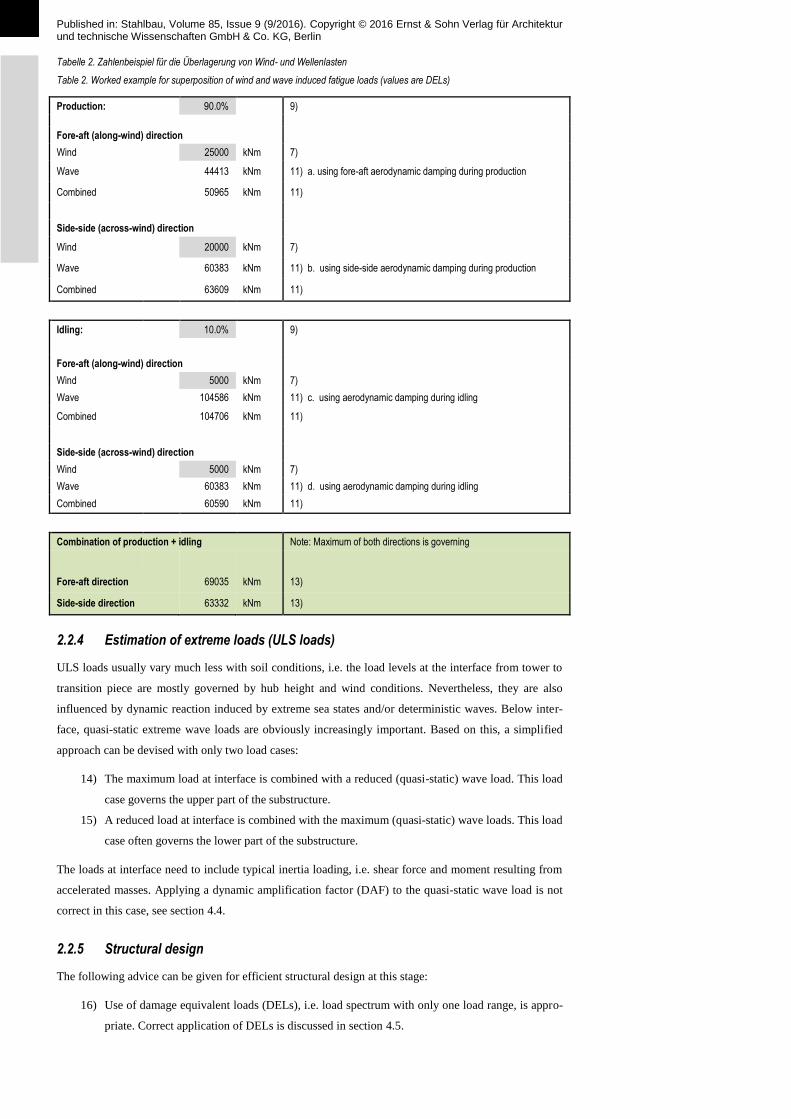
A complete example is given in Table 2. The last column refers to the numbered steps as described be-
fore.
Published in: Stahlbau, Volume 85, Issue 9 (9/2016). Copyright © 2016 Ernst & Sohn Verlag für Architektur und technische Wissenschaften GmbH & Co. KG, Berlin
Tabelle 2. Zahlenbeispiel für die Überlagerung von Wind- und Wellenlasten
Table 2. Worked example for superposition of wind and wave induced fatigue loads (values are DELs)
Production: 90.0%
9)
Fore-aft (along-wind) direction
Wind
25000 kNm 7)
Wave
44413 kNm 11) a. using fore-aft aerodynamic damping during production
Combined
50965 kNm 11)
Side-side (across-wind) direction
Wind
20000 kNm 7)
Wave
60383 kNm 11) b. using side-side aerodynamic damping during production
Combined
63609 kNm 11)
Idling: 10.0%
9)
Fore-aft (along-wind) direction
Wind
5000 kNm 7)
Wave
104586 kNm 11) c. using aerodynamic damping during idling
Combined
104706 kNm 11)
Side-side (across-wind) direction
Wind
5000 kNm 7)
Wave
60383 kNm 11) d. using aerodynamic damping during idling
Combined
60590 kNm 11)
Combination of production + idling Note: Maximum of both directions is governing
Fore-aft direction 69035 kNm 13)
Side-side direction 63332 kNm 13)
2.2.4 Estimation of extreme loads (ULS loads)
ULS loads usually vary much less with soil conditions, i.e. the load levels at the interface from tower to
transition piece are mostly governed by hub height and wind conditions. Nevertheless, they are also
influenced by dynamic reaction induced by extreme sea states and/or deterministic waves. Below inter-
face, quasi-static extreme wave loads are obviously increasingly important. Based on this, a simplified
approach can be devised with only two load cases:
14) The maximum load at interface is combined with a reduced (quasi-static) wave load. This load
case governs the upper part of the substructure.
15) A reduced load at interface is combined with the maximum (quasi-static) wave loads. This load
case often governs the lower part of the substructure.
The loads at interface need to include typical inertia loading, i.e. shear force and moment resulting from
accelerated masses. Applying a dynamic amplification factor (DAF) to the quasi-static wave load is not
correct in this case, see section 4.4.
2.2.5 Structural design
The following advice can be given for efficient structural design at this stage:
16) Use of damage equivalent loads (DELs), i.e. load spectrum with only one load range, is appro-
priate. Correct application of DELs is discussed in section 4.5.

Published in: Stahlbau, Volume 85, Issue 9 (9/2016). Copyright © 2016 Ernst & Sohn Verlag für Architektur und technische Wissenschaften GmbH & Co. KG, Berlin
17) ULS is usually only relevant for tower top, flanges, grouted connection and embedment depth.
ULS checks can be omitted otherwise.
18) Overall dimensions and mass are governed by FLS. Therefore, FLS checks need to be per-
formed with good accuracy. The following items are important:
a. Estimate of stress concentration factors for relevant attachment (e.g. boat landings)
b. Consideration of stress concentration factors for girth welds (thickness transitions)
c. Appropriate choice of S-N-curves depending on corrosion protection concept
2.3 Basic Design
Based on the conceptual design geometry, load simulations are performed to refine the previously esti-
mated load levels. The focus of the design work is therefore to optimize all relevant input for fatigue load
simulations, mainly the setup of FLS loads cases, damping estimates and soil stiffness modelling, in
order to accurately predict natural frequency and mode shape.
2.3.1 Fatigue Limit State (FLS) loads
During Basic Design, fatigue loads are determined through time domain simulations. For the fatigue load
cases according to IEC 61400-3, up to 30000 time series are being simulated per load iteration for one
load position. In order to arrive at optimized load levels, it is important to consider full directionality and
all misalignment situations, as already discussed in section 2.1. Simplifications can be made, e.g. by
omitting separate simulations for opposite wind / wave directions and lumping occurrences in post-
processing.
Furthermore, it is important that all items that attract wave loading are defined (e.g. boat landings, anode
cages). Relevant properties to define are:
Dimensions and elevations
Positions on circumference
Areas and hydrodynamic coefficients for wave load calculations
Frequency domain calculations are still valuable at this stage, as they can be used to cross-check time
domain results and to estimate the sensitivity to considered changes in geometry, natural frequency, soil
stiffness assumptions, etc.
2.3.2 Ultimate Limit State (ULS) loads
For ULS, the estimates used in the Conceptual Design are replaced by the full load case table acc. to IEC
61400-3. For exposed sites, extreme wave loads are important and the following should be considered:
Appurtenances (like boat landings) increase extreme wave loads significantly. It is therefore
beneficial to take into account directional extreme waves, if major appurtenances are not
placed such that they are hit from the worst direction.
The worst case wave load has to consider all parameters: Water level, contemporaneous current
speeds, wave height and wave period. The governing combination of these parameters can in
most cases be determined with quasi-static wave load calculations. In cases with very steep
waves, additional checks on significance of dynamic reaction with varying wave periods might
be required.
2.3.3 Structural design
For the structural design, the following refinements are made:
Fatigue loads are now processed as load spectra or Markov matrices. Using DELs is not appro-

Published in: Stahlbau, Volume 85, Issue 9 (9/2016). Copyright © 2016 Ernst & Sohn Verlag für Architektur und technische Wissenschaften GmbH & Co. KG, Berlin
priate any more at this stage.
Stress concentration factors (SCFs) for appurtenances and other attachments are confirmed by
detailed Finite Element Analysis (FEA).
Additional geotechnical design checks (e.g. accumulation of permanent displacements and pore
pressure) are carried out.
The corrosion protection concept is detailed to such a level that all aspects affecting structural
design are defined.
The functional concept (e.g. location of electrical components) is fixed, such that locations of
platforms, flanges, etc. are known.
2.4 Detailed Design
Detailed Design is mainly a continuation of Basic Design, amending minor details. For structural design,
the outstanding item might be interpolation from the limited number of load design positions to all posi-
tions within the wind farm. This interpolation needs to take into account all relevant parameters:
Water depth
Soil stiffness
Natural frequency and mode shape
Damping (if assumed differently across the site)
A method how this can be achieved is described by Seidel [4].
3 Design approaches for Jackets
Jacket design differs significantly from Monopile design, as jackets are governed by wind / turbulence
induced loads for both FLS and ULS. Extreme wave loading is in most cases only relevant for the lower
part of the jacket and the foundations (piles or suction buckets).
3.1 Conceptual Design
For the conceptual design, “wind only” loads at interface are sufficient. These can be determined by the
wind turbine manufacturer based on site parameters and estimated natural frequency.
For FLS analysis, the use of DELs is possible, but requires some simplifications and comparison / expe-
rience with full designs is needed to make this a reliable process. Generally, the following can be applied
(for both FLS and ULS):
Jacket legs are dominated by shear / moment at interface and good results can be achieved by
simultaneous application of these loads for assessment.
Bracings and nodes are dominated by torsion, but also some in-plane bending (IPB) originates
from shear / moment. As torsion and shear / moment are uncoupled load effects, a simplified
assessment can be justified where e.g. the following is applied:
o 100% shear/moment + 50% torsion
o 50% shear/moment + 100% torsion
o The maximum of the above combinations is used for design
For superposition of wind and wave loads (for overturning force/moment) a practical approach
is presented in [5]. Based on statistical considerations, a superposition following “Turkstra’s
rule” is suggested, where mean loads of one source are combined with maximum loads from
the other source.
Waves are mostly irrelevant for FLS. This can be checked separately and if significant contri-
bution from waves is found, then some margin should be left.

Published in: Stahlbau, Volume 85, Issue 9 (9/2016). Copyright © 2016 Ernst & Sohn Verlag für Architektur und technische Wissenschaften GmbH & Co. KG, Berlin
For long and slender bracings, local vibrations can be a significant contribution to fatigue
loads. This is difficult to assess at this stage and estimates based on experience need to be
made. It is useful to compare natural frequencies of the local brace modes with excitation fre-
quencies from the turbine, in particular multiples of the rotational and blade passing frequen-
cies, and try to avoid those.
Based on the conceptual design results, the main design parameter can be fixed, i.e.:
Three legged or four legged jacket
Number of bays
Brace layout
Foundation concept
3.2 Basic Design
During Basic Design, a major step is to move towards integrated load simulations. It is important to note
that only the following methods are acceptable:
1. Model the jacket by means of superelements with sufficient number of internal modes (conver-
gence), see [6].
2. Fully coupled models – those are not practical due to the excessive simulation time needed.
The superelement method is equivalent in accuracy, yet much faster.
In case of coupling the WTG and tower model to a jacket superelement, special care should be taken to
maintain model consistency during the process. It is not acceptable to e.g. use different software packag-
es for generation of superelements and recovery of internal forces, as those will always have differences,
which can have a major impact, even though they might be perceived as minor.
The availability of suitable software to the jacket designer is therefore essential. Such software must have
the following features:
1. Capability to generate superelements and associated generalized loading
2. Cluster-based computation to process a large number of time series (i.e. no license restrictions)
3. Ability to perform recovery runs to generate internal member forces, mostly by transient re-
covery runs using interface forces/moments or displacements/rotations. The latter is preferred,
as using forces/moments is more sensitive to small modelling discrepancies.
4. The most robust and time efficient method (but requiring exchange of larger data sets between
turbine manufacturer and foundation designer) is direct expansion of superelement results. This
requires converged superelements (i.e. including many modes). The superelements need to be
created by the FD, such that he has access to the reduction basis. This is visualized in Fig. 3.
Bild 3. Modale Superposition
Fig. 3. Modal superposition

Published in: Stahlbau, Volume 85, Issue 9 (9/2016). Copyright © 2016 Ernst & Sohn Verlag für Architektur und technische Wissenschaften GmbH & Co. KG, Berlin
3.3 Detailed Design
During detailed design, the final decision is made on grouping of locations and jacket heights. Also,
individual design for foundations is performed – at least in case of piles, while grouping might be more
suitable for suction buckets.
4 Important design aspects / pitfalls
4.1 Lumping of sea states
Often, correlations are used for the sea states to correlate HS-Vhub and HS-TP. This is possible, but it
should be noted that correct lumping of sea states is frequency dependent, see Seidel [4].
When selecting representative sea states for simulation, it needs to be realized that spectral energy varies
rapidly with frequency. As an example a sea state with a peak frequency of TP=4.5s is shown in Fig. 4. If
that sea state is applied to a structure with f0=0.222Hz, then the spectral energy is more than 3 times
higher compared to applying it to structures with f0=0.20Hz and f0=0.25Hz.
Bild 4. Beispiel für ein JONSWAP-Spektrum für HS=2.0m und TP=4.5s - die vertikalen Linien markieren Frequenzen von 0.2Hz,
0.222Hz and 0.25Hz
Fig. 4. Example of JONSWAP spectrum for a significant wave height of HS=2.0m and a peak period of TP=4.5s – vertical lines
mark frequencies of 0.2Hz, 0.222Hz and 0.25Hz
Based on this, an “equivalent spectral energy” S(0)eq can be calculated as follows, see [2] for details:
2/1
0,,
0
||
m
n
m
n
nPnS
eqnp
npTHS
S
(5)
This equivalent spectral energy can easily be computed and is a good indication of how much fatigue
loads vary with first natural frequency of the structure.

Published in: Stahlbau, Volume 85, Issue 9 (9/2016). Copyright © 2016 Ernst & Sohn Verlag für Architektur und technische Wissenschaften GmbH & Co. KG, Berlin
4.2 Effect of stiffness changes for monopiles
Stiffness changes due to structural changes and/or changes in soil stiffness assumptions have a severe
impact on resulting loads levels. This effect has two main sources:
Effect of equivalent spectral energy with decreasing natural frequency (see previous section) –
typically, the equivalent spectral energy at the first natural frequency increases with decreasing
frequency (see Fig. 5).
Effect of the mode shape – a larger (relative to hub height) mode shape amplitude around mean
sea level (MSL) causes higher generalized loading, which leads to higher loads even for un-
changed natural frequency. This is often the governing effect.
Bild 5. Äquivalente (gewichtete) spektrale Energie in Abhängigkeit der ersten Eigenfrequenz
Fig. 5. Equivalent (weighted) spectral energy vs. first natural frequency
4.3 Wave load generation
For time domain simulations, the wave spectrum is discretized into a finite number of individual wave-
lets, and structural response occurs at the frequencies of the individual wavelets. For monopile structures
with low damping, the response occurs almost exclusively around the first natural frequency of the struc-
ture, as the dynamic amplification function (DAF) is very steep, with a maximum of DAF=50 at the first
natural frequency for a damping of 1% of critical damping (see Fig. 6). It is therefore important that
wavelets around the first natural frequencies are sufficiently closely spaced to accurately capture this
narrow peak. This can be achieved by refinement of wavelet density around the first natural frequency.
Note that the dynamic amplification factor should not be used as a multiplier for use with quasi-static
loads, but only as an indication where structural response occurs, also see next section.
When generating time series of wave loads, care should be exercised regarding the discretization of line
loads and treatment of partially wetted members. This usually requires a sufficiently small element size
within the wave loaded zones to avoid step changes in wave loading.

Published in: Stahlbau, Volume 85, Issue 9 (9/2016). Copyright © 2016 Ernst & Sohn Verlag für Architektur und technische Wissenschaften GmbH & Co. KG, Berlin
Bild 6. Wellenenergiespektrum (blaue Kurve, recht y-Achse) und dynamischer Überhöhungsfaktor (rote Kurve, linke y-Achse)
Fig. 6. Wave spectrum (blue curve, right y-axis) and dynamic amplification factor (red curve, left y-axis)
4.4 Inappropriate calculation methods
Sometimes, calculation methods are used by designers which are not appropriate. A prominent example
is the application of “Dynamic Amplification Factors” (DAFs) to wave loads. Such DAFs are meaningful
if the general shape of the bending moment line is similar for external loading and inertia (acceleration)
induced loads. This is e.g. the case for a chimney under wind load. For general offshore structures, this
concept is already questionable, but due to the limited impact this concept is still sometimes applied. For
offshore wind turbines, this method delivers completely erroneous results, as the moment shapes from
wave loading and inertia induced loads are different:
Quasi-static wave loading creates moments only below wave crest.
Inertia induced loading, originating from vibrations in the fundamental mode, is dominated by
the inertia forces from the nacelle mass. This results in a moment line which increases almost
linearly from tower top to mudline (some contribution from the support structures masses
makes the shape slightly curved).
It is obvious that any factor on the quasi-static wave loading will not result in the correct contribution
from inertia. This principle is illustrated in Fig. 7.
Bild 7. Falsche Anwendung des dynamischen Überhöhungsfaktors [4]
Fig. 7. Incorrect DAF concept application [4]

Published in: Stahlbau, Volume 85, Issue 9 (9/2016). Copyright © 2016 Ernst & Sohn Verlag für Architektur und technische Wissenschaften GmbH & Co. KG, Berlin
4.5 Correct use of damage equivalent loads (DELs)
Another mistake which has repeatedly been made in the past is incorrect application of damage equiva-
lent loads (DELs). DELs are calculated based on the assumption of a single slope S-N-curve, often m=4
or m=5 for steel. Therefore, also the design checks need to be performed with the same single slope!
Applying DELs together with codified S-N-curves (which often have slopes of m=3 and m=5), leads to
incorrect results.
In Fig. 8 two options are shown how S-N-curves can be chosen to arrive at meaningful results:
A conservative approach is to use DELs for m=5 together with an S-N-curve where the m=5
part of the curve is extended “backwards” (i.e. towards smaller number of cycles). Difference
in S-N-curves between Eurocode and DNV-GL with different number of cycles at the knee
point must be observed.
A practical approach, which is less conservative, is to use DELs for m=4 with an S-N-curve
(with m=4), which intersects the codified S-N-curve at N=2E6 (this is the reference number of
cycles in Eurocode 3).
DELs can easily be converted to different number of reference cycles if needed:
)/1(
2
1
1,2,
m
ref
ref
NrefeqNrefeqN
NMM
(6)
Note that conversion to another S-N-curve slope m is not possible!
Bild 8. Ermüdungsfestigkeitskurven (S-N-Kurve) für die Verwendung mit Einstufenkollektiven
Fig. 8. S-N-curve to be used with DELs

Published in: Stahlbau, Volume 85, Issue 9 (9/2016). Copyright © 2016 Ernst & Sohn Verlag für Architektur und technische Wissenschaften GmbH & Co. KG, Berlin
5 Summary
In this paper, methods have been described which can be used during different stages of the design pro-
cess of support structures of offshore wind turbines. The authors hope that the publication of this
knowledge enables project owners and designers to organize their design processes more efficiently and
to avoid common mistakes.
References
[1] Versteijlen, W.G. et al.: A method for identification of an effective Winkler foundation for large-
diameter offshore wind turbine support structures based on in-situ measured small-strain soil re-
sponse and 3D modelling. Engineering Structures (2016), pp. 221-236.
DOI: 10.1016/j.engstruct.2016.06.007
[2] Seidel, M.: Wave induced fatigue loads - Insights from frequency domain calculations. Stahlbau 83
(2014), p. 535-541. doi: 10.1002/stab201410184
[3] Kühn, M.: Dynamics and Design Optimisation of Offshore Wind Energy Conversion Systems.
Ph.D. thesis, Delft 2001.
[4] Seidel, M.: Wave induced fatigue loads on monopiles – New approaches for lumping of scatter
tables and site specific interpolation of fatigue loads. Hannover: IWEC conference proceedings
2014.
[5] Seidel, M.; Kelma, S.: Stochastic modelling of wind and wave induced loads on jacket piles.
Stahlbau, 81: 705–710. doi: 10.1002/stab.201201599
[6] Van der Valk, P.; Voormeeren, S.N.: Dynamic models for load calculation procedures of offshore
wind turbine support structures: Overview, assessment and outlook. Journal of Computational and
Nonlinear Dynamics, 2014. DOI:10.1115/1.4028136
Autoren dieses Beitrages:
Dr.-Ing. Marc Seidel
Siemens AG
Beim Strohhause 17-31
20097 Hamburg
Email: [email protected]
Dr. Sven Voormeeren, Jan-Bart van der Steen (MSc)
Siemens Nederland N.V.
Prinses Beatrixlaan 800
2595 BN Den Haag, Netherlands