Embed Size (px)
Citation preview
ISDBT WorkshopMarch 12, 2015
Manila, Philippines
Copyright © 2015 GatesAir, Inc. All rights reserved.
FeaturingGatesAir’s
Martyn HorspoolProduct Manager,TV Transmission
Proprietary and confidential. | 1
Connecting What’s Next
Connecting What’s Next
ISDBT Workshop
Manila, Philippines, March 12, 2015
Martyn HorspoolProduct Manager, TV TransmissionGatesAir
Manila, Philippines

Proprietary and confidential. | 2
Connecting What’s Next
Welcome/Introductions GatesAir… Brief Introduction and History Review of COFDM Modulation Characteristics (on thumb drive only) ISDB-T Overview/Training ISDB-T Single Frequency Network (SFN) and GatesAir Solution ISDB-T Coverage and Planning New High-Efficiency Transmitter Products for ISDB-T:
– High Power Liquid-Cooled Solid State (ULXT)– Low and Medium Power Air-Cooled Solid State (UAXT & UAXT Ultra Compact)
GA experience and Site References for ISDB-T Deployments Challenges and Lessons Learned Q&A and lucky draw for prizes
Today’s Agenda

Proprietary and confidential. | 3
Connecting What’s Next
Connecting What’s Next
Brief Overview and History
Quincy IL, USA
GatesAir
Proprietary and confidential. | 4
Connecting What’s Next
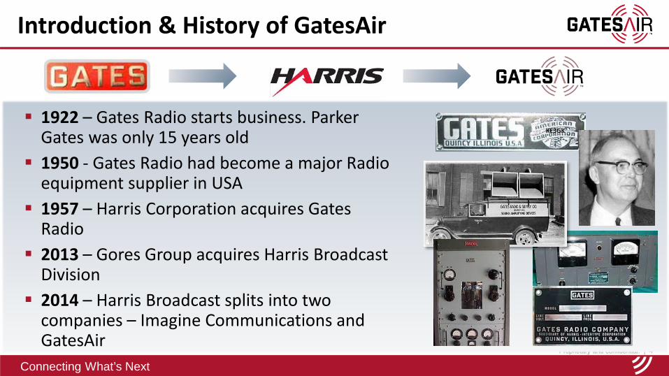
1922 – Gates Radio starts business. Parker Gates was only 15 years old
1950 - Gates Radio had become a major Radio equipment supplier in USA
1957 – Harris Corporation acquires Gates Radio
2013 – Gores Group acquires Harris Broadcast Division
2014 – Harris Broadcast splits into two companies – Imagine Communications and GatesAir
Introduction & History of GatesAir
Proprietary and confidential. | 5
Connecting What’s Next
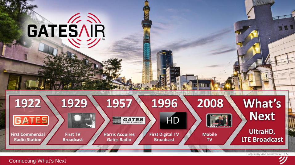
1929
First TV Broadcast
First Digital TVBroadcast
1996
UltraHD,LTE Broadcast
What’sNext
Mobile TV
2008
Harris AcquiresGates Radio
19571922
First CommercialRadio Station
Proprietary and confidential. | 6
Connecting What’s Next6
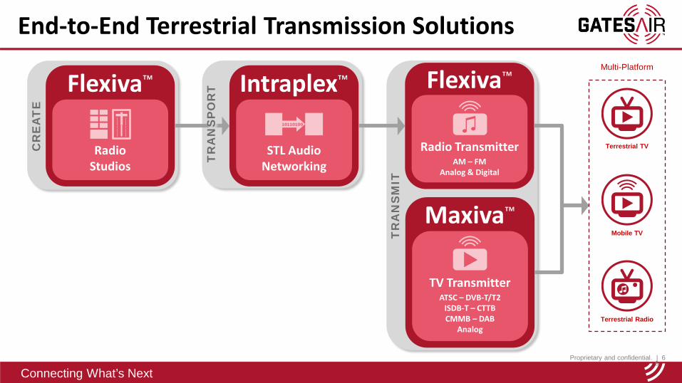
End-to-End Terrestrial Transmission Solutions
Flexiva™
Radio Studios
Intraplex™
STL Audio Networking
Maxiva™
TV TransmitterATSC – DVB-T/T2
ISDB-T – CTTBCMMB – DAB
Analog
Flexiva™
Radio TransmitterAM – FM
Analog & Digital
CR
EA
TE
TR
AN
SM
IT
Terrestrial TV
Mobile TV
Terrestrial Radio
Multi-Platform
TR
AN
SP
OR
TT
RA
NS
PO
RT
Proprietary and confidential. | 7
Connecting What’s Next7
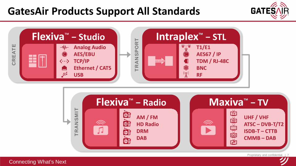
GatesAir Products Support All Standards
Flexiva™ − Studio Intraplex™ − STL
Flexiva™ − Radio
CR
EA
TE
TR
AN
SP
OR
T
TR
AN
SM
IT
Maxiva™ − TV
Analog AudioAES/EBUTCP/IPEthernet / CAT5USB
AM / FMHD RadioDRMDAB
UHF / VHFATSC – DVB-T/T2ISDB-T – CTTBCMMB – DAB
T1/E1AES67 / IPTDM / RJ-48CBNCRF

Proprietary and confidential. | 8
Connecting What’s Next
Market leader in transmission solutions for core broadcasters, network operators and government-sponsored broadcast networks Lowest transmission total cost of ownership
(TCO) for broadcasters worldwide Innovative, world class products that solve
evolving customer needs Exceptional pre- and post-sales services Unique capability to deliver transmission
solutions that enable new revenue
Best-In-Class Transmission Solutions
Proprietary and confidential. | 9
Connecting What’s Next
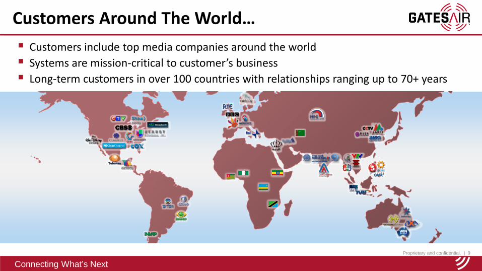
Customers Around The World… Customers include top media companies around the world Systems are mission-critical to customer’s business Long-term customers in over 100 countries with relationships ranging up to 70+ years

Proprietary and confidential. | 10
Connecting What’s Next
Committed to Providing the Best Service
We do what it takes to help our customers succeed 24/7 service with training centers, repair centers,
and parts depots around the world Our support teams consist of innovative technical
experts who can offer project planning and management, on-site service, and commissioning
Support situations involving product performance, integration, and operational processing
Superior, industry-competitive warranties Service package options are available
Proprietary and confidential. | 11
Connecting What’s Next
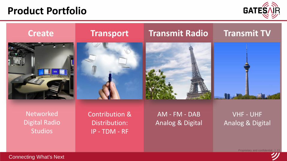
Product Portfolio
Create
Networked Digital Radio
Studios
Transport
Contribution & Distribution:IP - TDM - RF
Transmit Radio
AM - FM - DABAnalog & Digital
VHF - UHFAnalog & Digital
Transmit TV
Proprietary and confidential. | 12
Connecting What’s Next12
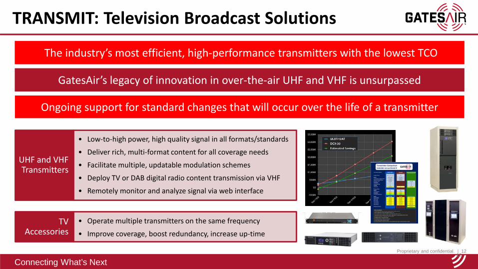
UHF and VHF Transmitters
• Low-to-high power, high quality signal in all formats/standards
• Deliver rich, multi-format content for all coverage needs
• Facilitate multiple, updatable modulation schemes
• Deploy TV or DAB digital radio content transmission via VHF
• Remotely monitor and analyze signal via web interface
TV Accessories
• Operate multiple transmitters on the same frequency
• Improve coverage, boost redundancy, increase up-time
TRANSMIT: Television Broadcast Solutions
The industry’s most efficient, high-performance transmitters with the lowest TCO
GatesAir’s legacy of innovation in over-the-air UHF and VHF is unsurpassed
Ongoing support for standard changes that will occur over the life of a transmitter
Proprietary and confidential. | 13
Connecting What’s Next
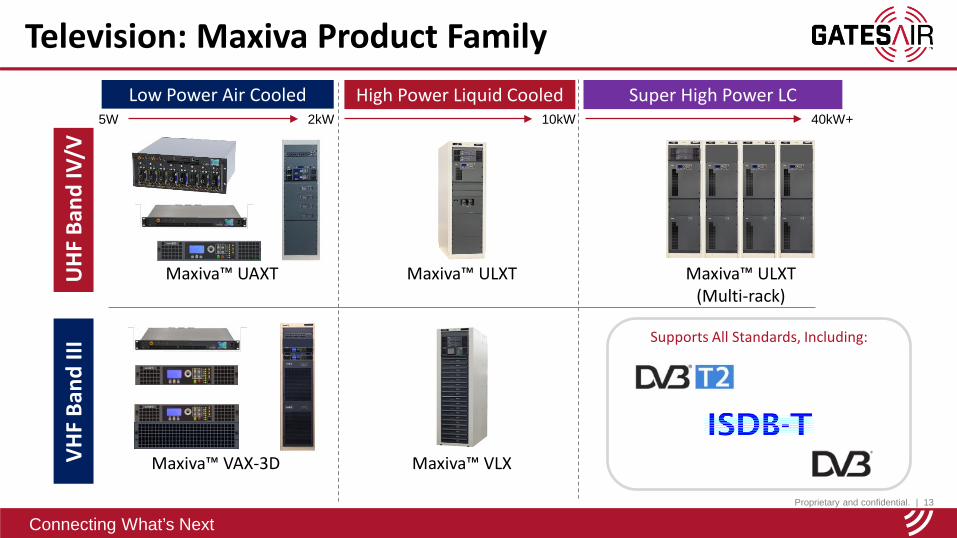
Television: Maxiva Product Family
Supports All Standards, Including:
UH
F Ba
nd IV
/VSuper High Power LC
Maxiva™ ULXT(Multi-rack)
Maxiva™ ULXTMaxiva™ UAXT
Low Power Air Cooled High Power Liquid CooledVH
F Ba
nd II
I
Maxiva™ VLXMaxiva™ VAX-3D
40kW+10kW2kW5W
Proprietary and confidential. | 14
Connecting What’s Next
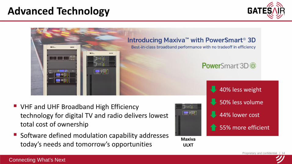
Advanced Technology
VHF and UHF Broadband High Efficiency technology for digital TV and radio delivers lowest total cost of ownership Software defined modulation capability addresses
today’s needs and tomorrow’s opportunitiesMaxiva ULXT
40% less weight
50% less volume
44% lower cost
55% more efficient
Proprietary and confidential. | 15
Connecting What’s Next
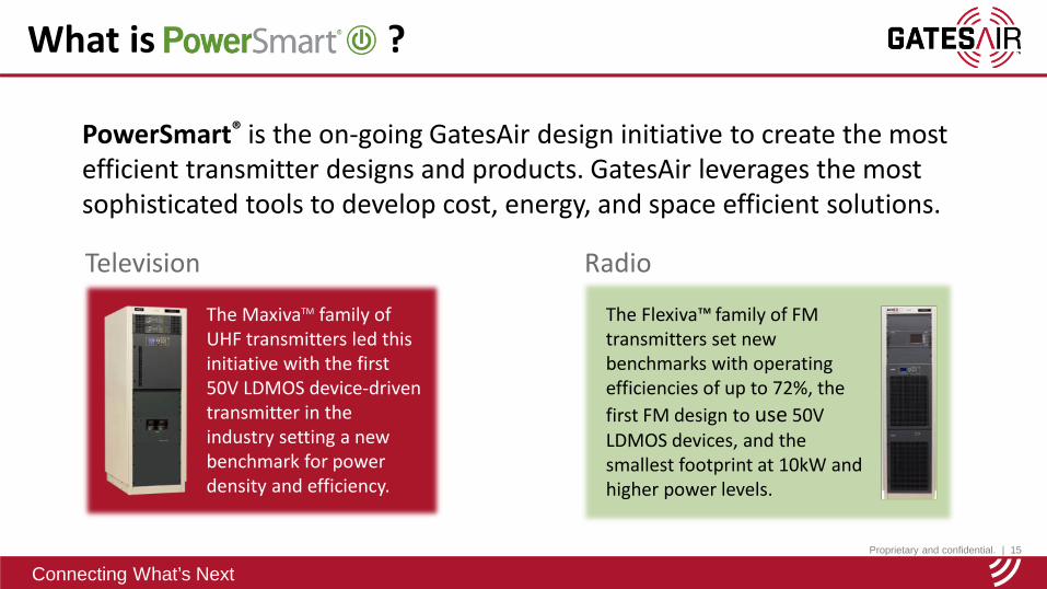
PowerSmart® is the on-going GatesAir design initiative to create the most efficient transmitter designs and products. GatesAir leverages the most sophisticated tools to develop cost, energy, and space efficient solutions.
What is ?
Radio
The Flexiva™ family of FM transmitters set new benchmarks with operating efficiencies of up to 72%, the first FM design to use 50V LDMOS devices, and the smallest footprint at 10kW and higher power levels.
Television
The MaxivaTM family of UHF transmitters led this initiative with the first 50V LDMOS device-driven transmitter in the industry setting a new benchmark for power density and efficiency.
Proprietary and confidential. | 16
Connecting What’s Next
Actively Defining the Future of Broadcasting
GatesAir is an active member, partneredwith, or sponsors: ATSC DVB Project Office World DMB DRM Consortium Ibiquity (HD Radio) Mackenzie University, São Paulo, Brazil ABU, Asia-Pacific Broadcast Union
Proprietary and confidential. | 17
Connecting What’s Next
Connecting What’s Next
Review of COFDM Modulation Characteristics
Hundred Islands National Park - Philippines
Proprietary and confidential. | 21
Connecting What’s Next
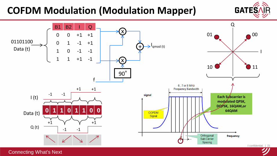
COFDM Modulation (Modulation Mapper) B1 B2 I Q
0 0 +1 +1
0 1 -1 +1
1 0 -1 -1
1 1 +1 -1
90°
Data (t)Iqmod (t)
x
x
+01101100
Data (t) 0 1 1 0 1 1 0 0
I (t)-1
-1
+1 +1
+1
-1
-1+1
Q (t)
Each Subcarrier is modulated QPSK, DQPSK, 16QAM,or
64QAM
f
Q
I
0001
10 11

Proprietary and confidential. | 22
Connecting What’s Next
Modulation (Visualization of COFDM Modulation)
time(n-2) (n-1)
... 0 1 1 0 0 0 1 0 1 1 0 1 1 0 0 1 0 1 0 1 0 1 0 0 1 1 0 0 0 1 0 1 ... Data Stream
0 1 1 0 0 0 1 0Separationinto Symbols
COFDMModulation
Guard Interval
1 1 0 1 1 0 0 1
(n)
Useful Symbol Duration
(n+1)
1 1 0 1 1 0 0 1 1 1 0 1 1 0 0 1
(n+2)
Proprietary and confidential. | 23
Connecting What’s Next
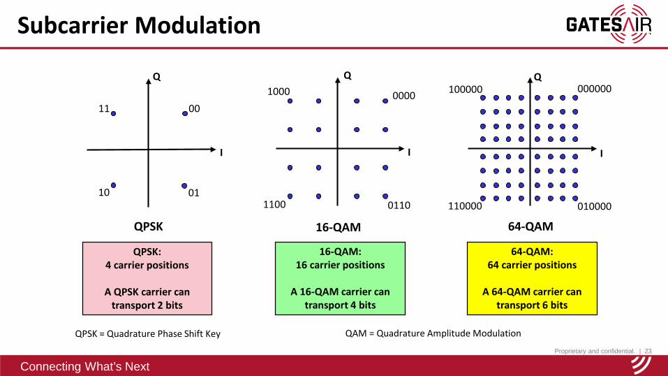
Subcarrier Modulation
I
Q
QPSK
00
0110
11
QPSK: 4 carrier positions
A QPSK carrier can transport 2 bits
I
Q
16-QAM
0000
1100 0110
1000
16-QAM: 16 carrier positions
A 16-QAM carrier can transport 4 bits
I
Q
64-QAM
64-QAM: 64 carrier positions
A 64-QAM carrier can transport 6 bits
QPSK = Quadrature Phase Shift Key QAM = Quadrature Amplitude Modulation
100000 000000
110000 010000
Proprietary and confidential. | 24
Connecting What’s Next
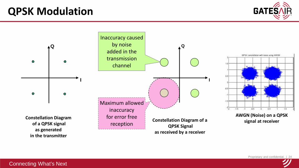
QPSK Modulation
Constellation Diagram of a QPSK signal
as generated in the transmitter
Constellation Diagram of a QPSK Signal
as received by a receiver
I
Q
Inaccuracy causedby noise
added in the transmission
channel
Maximum allowedinaccuracy
for error freereception
I
Q
AWGN (Noise) on a QPSK signal at receiver
Proprietary and confidential. | 25
Connecting What’s Next
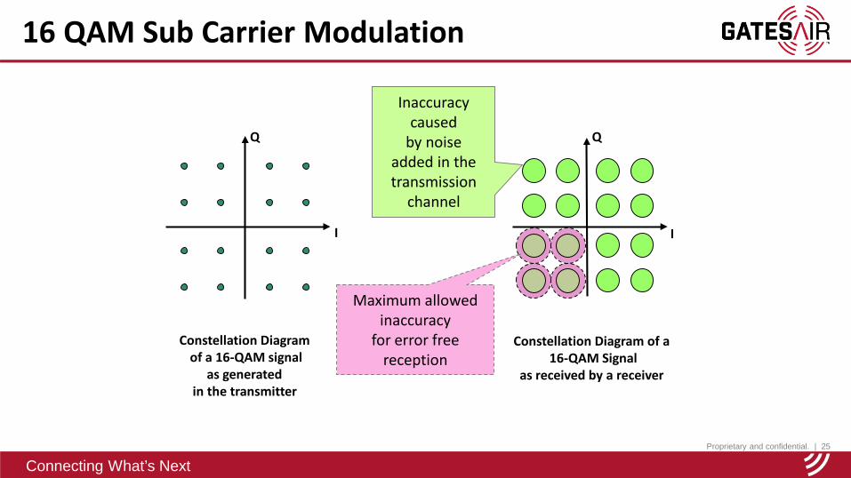
16 QAM Sub Carrier Modulation
I
Q
Constellation Diagram of a 16-QAM signal
as generated in the transmitter
Constellation Diagram of a 16-QAM Signal
as received by a receiver
Inaccuracy caused
by noiseadded in the transmission
channel
I
Q
Maximum allowedinaccuracy
for error freereception
Proprietary and confidential. | 26
Connecting What’s Next
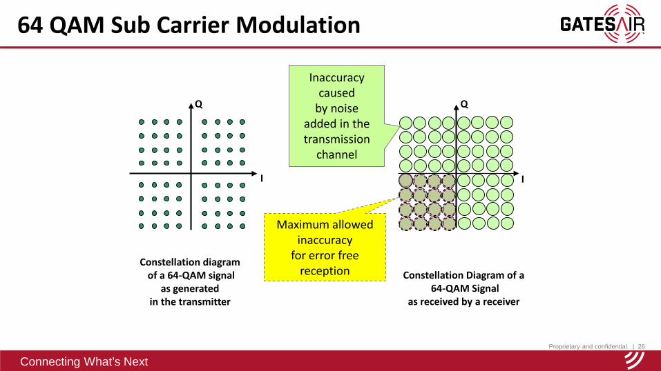
64 QAM Sub Carrier Modulation
I
Q
I
Q
Inaccuracy caused
by noiseadded in the transmission
channel
Maximum allowedinaccuracy
for error freereception Constellation Diagram of a
64-QAM Signalas received by a receiver
Constellation diagram of a 64-QAM signal
as generated in the transmitter
Proprietary and confidential. | 27
Connecting What’s Next
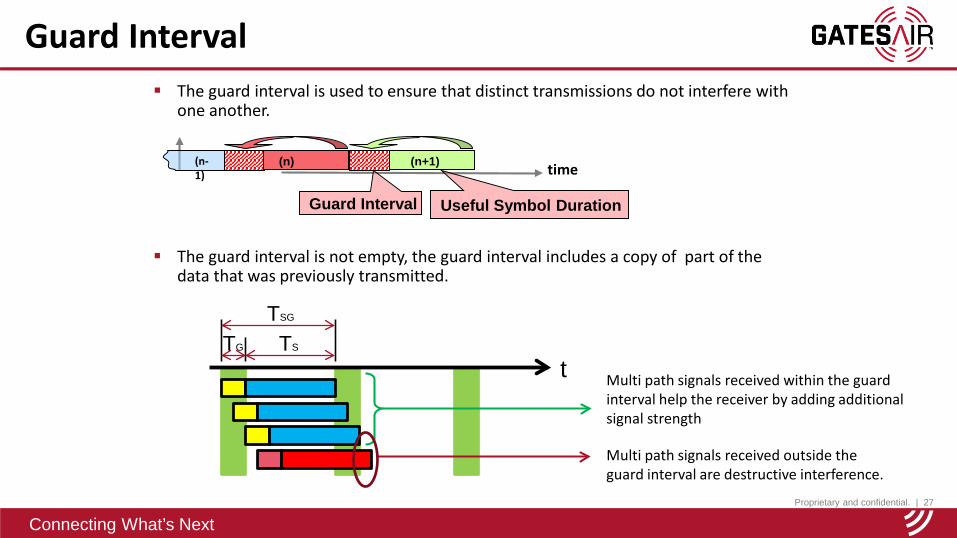
Guard Interval The guard interval is used to ensure that distinct transmissions do not interfere with
one another.
The guard interval is not empty, the guard interval includes a copy of part of the data that was previously transmitted.
time(n-1)
(n)
Guard Interval
(n+1)
Useful Symbol Duration
TSG
TG TS
t Multi path signals received within the guard interval help the receiver by adding additional signal strength
Multi path signals received outside the guard interval are destructive interference.

Proprietary and confidential. | 28
Connecting What’s Next
COFDM Modulation (No Interleaving) Position of sub symbols in the incoming bit streamu
t1 2 6 n-2 n0 3 4 5 n-1............
............u
t0 1 2 3 4 5 6 n-2 n-1 n............
............
Position of sub symbols assigned to the sub carriers in the OFDM signal is the same as their position in the incoming data stream
f
............
If several adjacent sub carriers are attenuated, as could happen with multipath or other types of interference, the adjacent data will be corrupted. This type of error is difficult for the forward error correction circuits to correct.
Proprietary and confidential. | 29
Connecting What’s Next
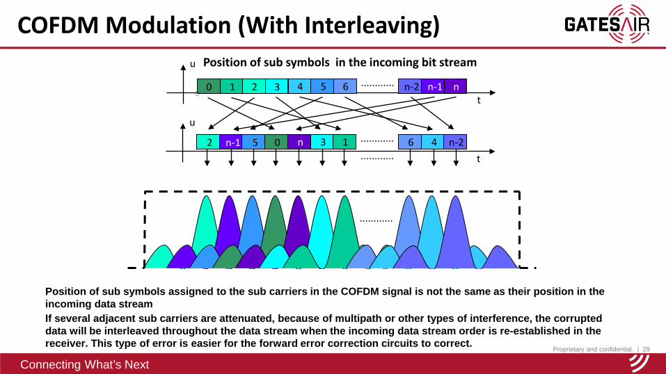
COFDM Modulation (With Interleaving)u
t0 1 2 3 4 5 6 n-2 n-1 n............
u
t2 n-1 5 0 n 3 1 6 4 n-2............
............
Position of sub symbols assigned to the sub carriers in the COFDM signal is not the same as their position in the incoming data streamIf several adjacent sub carriers are attenuated, because of multipath or other types of interference, the corrupted data will be interleaved throughout the data stream when the incoming data stream order is re-established in the receiver. This type of error is easier for the forward error correction circuits to correct.
............
Position of sub symbols in the incoming bit stream
Proprietary and confidential. | 30
Connecting What’s Next
Connecting What’s Next
ISDB-T Overview / Training
Philippines
Proprietary and confidential. | 31
Connecting What’s Next
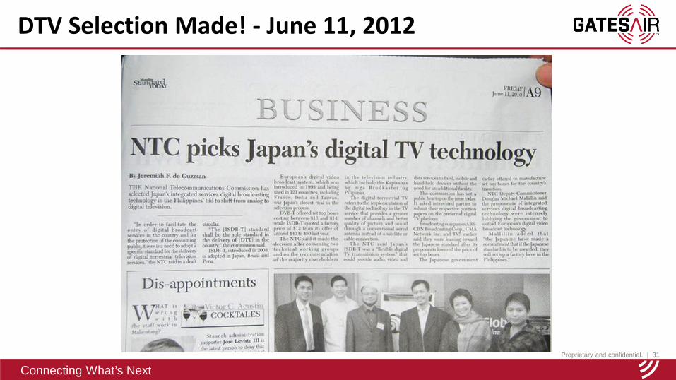
DTV Selection Made! - June 11, 2012

Proprietary and confidential. | 32
Connecting What’s Next
ISDB-Tb is derived from the Japanese ISDB-T digital terrestrial television standard. Also called ISDBT International Integrated Services Digital Broadcasting - Terrestrial brazil Defined by standard ABNT NBR 15601 It is very similar to the Japanese version Main differences are the use of a more efficient H.264/MPEG-4 HE AAC
video/audio Codec and new Middleware (Ginga) It is suitable for MFN and SFN applications It can transmit up to three hierarchical layers
ISDB-Tb – What is it?

Proprietary and confidential. | 33
Connecting What’s Next
ISDB-T Basic Transmission Parameters
Mode 1 Mode 2 Mode 3
Proprietary and confidential. | 34
Connecting What’s Next
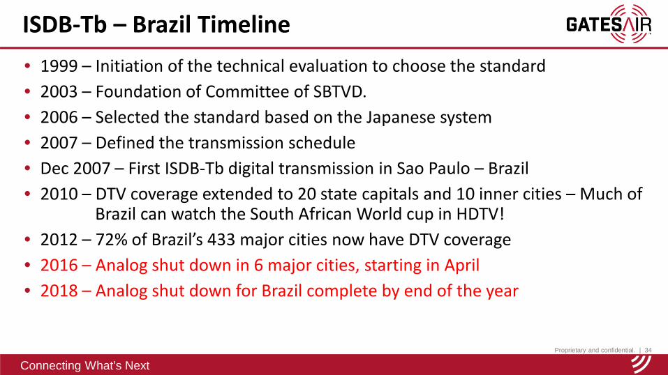
• 1999 – Initiation of the technical evaluation to choose the standard• 2003 – Foundation of Committee of SBTVD.• 2006 – Selected the standard based on the Japanese system • 2007 – Defined the transmission schedule• Dec 2007 – First ISDB-Tb digital transmission in Sao Paulo – Brazil• 2010 – DTV coverage extended to 20 state capitals and 10 inner cities – Much of
Brazil can watch the South African World cup in HDTV!• 2012 – 72% of Brazil’s 433 major cities now have DTV coverage• 2016 – Analog shut down in 6 major cities, starting in April• 2018 – Analog shut down for Brazil complete by end of the year
ISDB-Tb – Brazil Timeline

Proprietary and confidential. | 35
Connecting What’s Next
ISDB-Tb / InternationalBrazil, Argentina, Philippines, PeruChile, Botswana, OthersFull SegVideo: H264 – MPEG4 Part 10.Audio: HE-AAC (AAC+) 2.0 or 5.1One SegVideo: H264 a 30fpsAudio: HE-AAC v2 (Parametric stereo)MiddlewareGinga
ISDB-T Compared to ISDB-Tb/International
ISDB-TJapan
Full SegVideo: MPEG2Audio: MPEG2 Layer 3One SegVideo: H264 a 15fpsAudio: HE-AAC v1MiddlewareBML
Proprietary and confidential. | 36
Connecting What’s Next
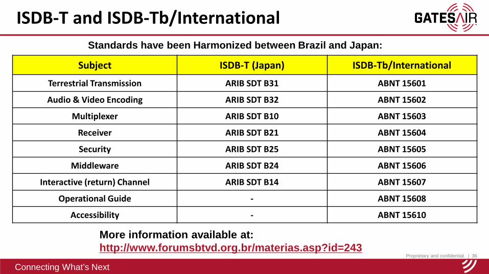
Subject ISDB-T (Japan) ISDB-Tb/International
Terrestrial Transmission ARIB SDT B31 ABNT 15601
Audio & Video Encoding ARIB SDT B32 ABNT 15602
Multiplexer ARIB SDT B10 ABNT 15603
Receiver ARIB SDT B21 ABNT 15604
Security ARIB SDT B25 ABNT 15605
Middleware ARIB SDT B24 ABNT 15606
Interactive (return) Channel ARIB SDT B14 ABNT 15607
Operational Guide - ABNT 15608
Accessibility - ABNT 15610
ISDB-T and ISDB-Tb/International
More information available at: http://www.forumsbtvd.org.br/materias.asp?id=243
Standards have been Harmonized between Brazil and Japan:

Proprietary and confidential. | 37
Connecting What’s Next
ISDB-Tb - Structure
Encoder HDAudioVídeo
Encoder SDAudioVídeo
Encoder LDAudioVídeo
M
U
X
TransportStream
Transport Stream
Transport Stream
TRANSMITTER
BTS **
Basic System Structure – High Level View
** Broadcast Transport Stream
RF
DATA

Proprietary and confidential. | 38
Connecting What’s Next
ISDB-Tb - Structure
Basic System Structure - Video and Audio Paths
Encoder HDAudioVídeo
Encoder SDAudioVídeo
Encoder LDAudioVídeo
Transport Stream
Transport Stream
Transport Stream
Audio: HE-AAC – 128Kbps
Vídeo: 1080i 16:9
Audio: HE-AAC – 128Kbps
Vídeo: 720p or 420p 16:9
Audio: HE-AAC v2 (parametric stereo) – 32Kbps
Vídeo: 320 x 240 QVGA 4:3

Proprietary and confidential. | 39
Connecting What’s Next
ISDB-Tb - Structure
Basic System Structure – TS – Transport Stream
Encoder HD MPEG4AudioVideo
Encoder SD MPEG4AudioVideo
Encoder LD MPEG4AudioVideo
Transport Stream
Transport Stream
Transport Stream
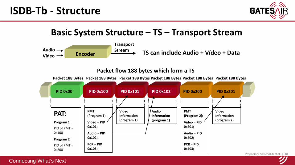
Each TS packet flow is compressed data derived from the transport layer of MPEG (Moving Picture Expert Group).
Each Packet Contains 188 Bytes.
Each packet of 188 bytes in the TS is identified with a PID (Packet IDentifier)
To identify the contents of each packet to the transport layer utilizes a set of MPEG tables:
– PAT (Program Association Table)
– PMT (Program Map Table)
– In addition the PCR (Program Clock Reference) is added
Proprietary and confidential. | 40
Connecting What’s Next
ISDB-Tb - Structure
EncoderAudioVídeo
Transport Stream TS can include Audio + Vídeo + Data
Packet flow 188 bytes which form a TS
PID 0x00
Packet 188 Bytes
PID 0x100
Packet 188 Bytes
PAT:Program 1
PID of PMT = 0x100
Program 2
PID of PMT = 0x200
PMT (Program 1):
Vídeo = PID 0x101;
Audio = PID 0x102;
PCR = PID 0x103;
Video Information (program 1)
Audio Information (program 1)
PID 0x101
Packet 188 Bytes
PID 0x102
Packet 188 Bytes
PMT (Program 2):
Vídeo = PID 0x201;
Audio = PID 0x202;
PCR = PID 0x203;
Video Information (program 2)
PID 0x200
Packet 188 Bytes
PID 0x201
Packet 188 Bytes
Basic System Structure – TS – Transport Stream
Proprietary and confidential. | 41
Connecting What’s Next
ISDB-Tb - Structure
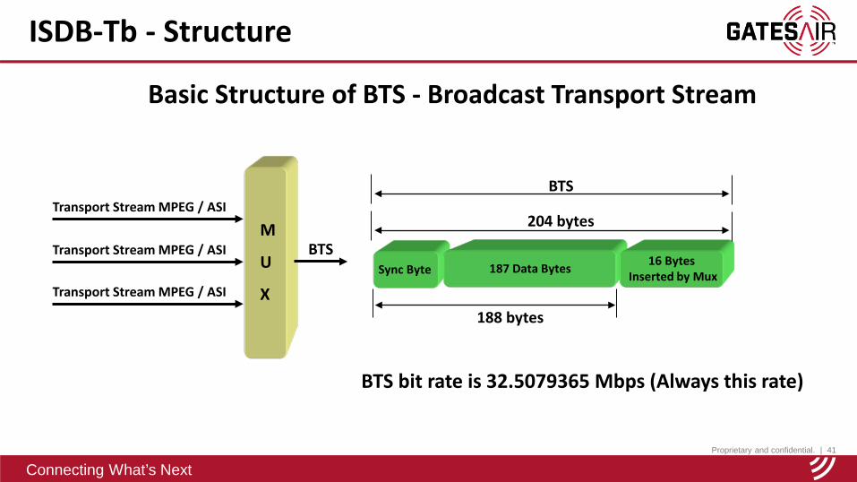
Basic Structure of BTS - Broadcast Transport Stream
M
U
X
Transport Stream MPEG / ASI
BTS Transport Stream MPEG / ASI
Transport Stream MPEG / ASI
Sync Byte 187 Data Bytes 16 Bytes Inserted by Mux
188 bytes
204 bytes
BTS
BTS bit rate is 32.5079365 Mbps (Always this rate)

Proprietary and confidential. | 42
Connecting What’s Next
ISDB-Tb - Structure
Sync Byte 187 Data Bytes 16 Bytes Inserted by Mux
188 bytes
204 bytes
BTS
Tables added by the MUX: NIT (Network Information Table) - Carries Network Information and Programs TOT (Time Offset Table) - Carries information from the current day and time to
update the Set-top box EIT (Event Information Table) - Carries data for program schedule
Basic Structure of BTS - Broadcast Transport Stream
Proprietary and confidential. | 43
Connecting What’s Next
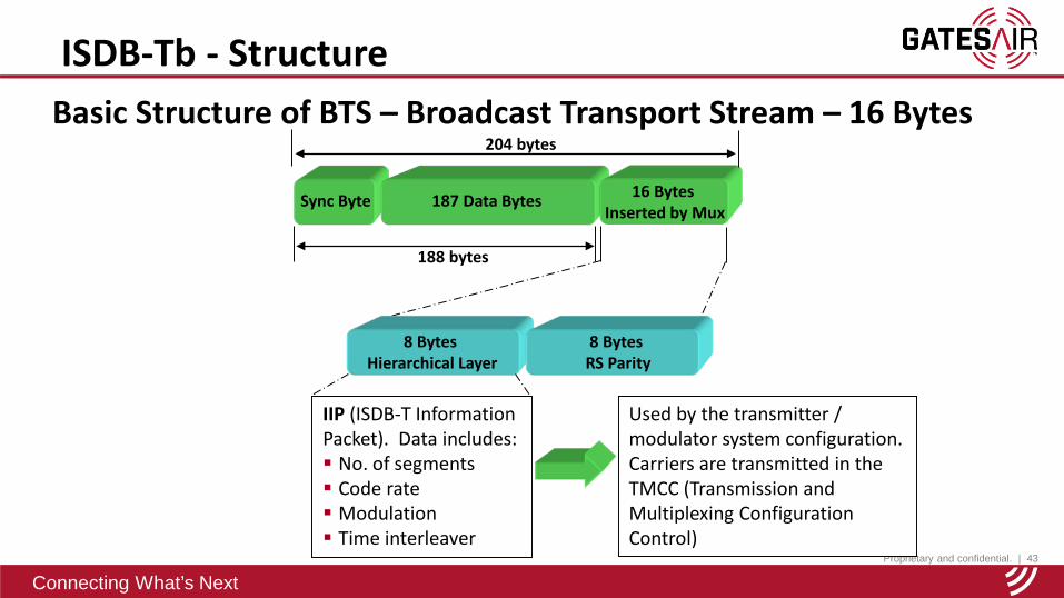
ISDB-Tb - StructureBasic Structure of BTS – Broadcast Transport Stream – 16 Bytes
Sync Byte 187 Data Bytes 16 Bytes Inserted by Mux
188 bytes
204 bytes
8 Bytes Hierarchical Layer
8 Bytes RS Parity
IIP (ISDB-T Information Packet). Data includes: No. of segments Code rate Modulation Time interleaver
Used by the transmitter / modulator system configuration.Carriers are transmitted in the TMCC (Transmission and Multiplexing Configuration Control)
Proprietary and confidential. | 44
Connecting What’s Next
ISDB-Tb - Structure
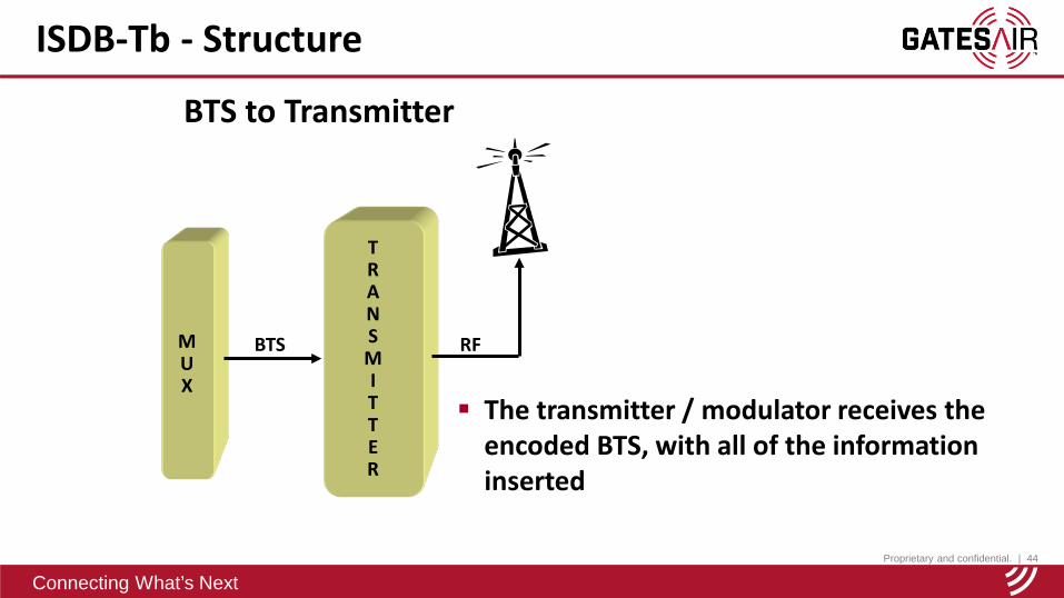
BTS to Transmitter
MUX
TRANSMITTER
BTS RF
The transmitter / modulator receives the encoded BTS, with all of the information inserted
Proprietary and confidential. | 45
Connecting What’s Next
ISDB-Tb - Structure
TRANSMITTER
RF
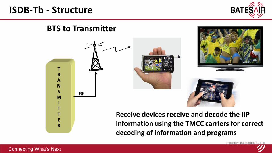
Receive devices receive and decode the IIP information using the TMCC carriers for correct decoding of information and programs
BTS to Transmitter

Proprietary and confidential. | 46
Connecting What’s Next
ISDB-Tb - Structure
M
U
X
BTS **
SYNC 187 Bytes 16 Bytes
188 bytes
204 bytes
Encoder HDAudioVídeo
Encoder SDAudioVídeo
Encoder LDAudioVídeo
Transport Stream
Transport Stream
Transport Stream
PID 0x00
PID 0x100
PID 0x101
PID 0x102
PID 0x200
PID 0x201
TS
Tables: PSI / SI ( Program Specific Information / Service Information)
- PAT (Program Association Table)
- PMT (Program Map Table)
- NIT (Network Information Table)
- TOT (Time Offset Table)
- EIT (Event Information Table)
- CAT (Conditional Access Table)
- SDT (Service Description Table)
Proprietary and confidential. | 47
Connecting What’s Next
ISDB-Tb – RF Channel
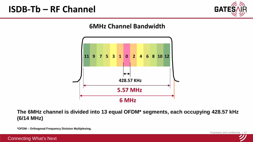
6MHz Channel Bandwidth
The 6MHz channel is divided into 13 equal OFDM* segments, each occupying 428.57 kHz (6/14 MHz)
*OFDM – Orthogonal Frequency Division Multiplexing.
11 29 7 5 3 1 0 4 6 8 10 12
6 MHz
5.57 MHz428.57 KHz
Proprietary and confidential. | 48
Connecting What’s Next
ISDB-Tb – RF Channel
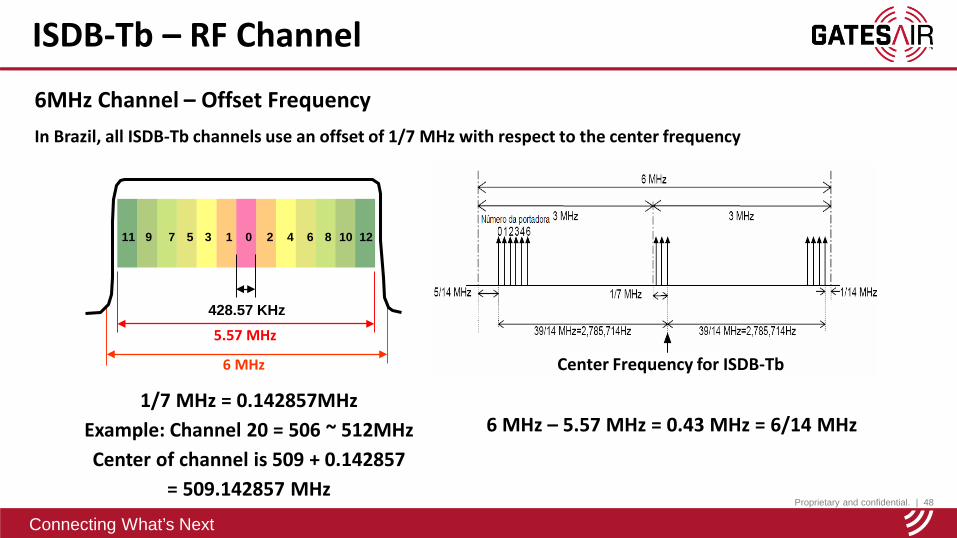
6MHz Channel – Offset FrequencyIn Brazil, all ISDB-Tb channels use an offset of 1/7 MHz with respect to the center frequency
6 MHz – 5.57 MHz = 0.43 MHz = 6/14 MHz1/7 MHz = 0.142857MHz
Example: Channel 20 = 506 ~ 512MHzCenter of channel is 509 + 0.142857
= 509.142857 MHz
Center Frequency for ISDB-Tb
11 29 7 5 3 1 0 4 6 8 10 12
6 MHz
5.57 MHz428.57 KHz
Proprietary and confidential. | 49
Connecting What’s Next
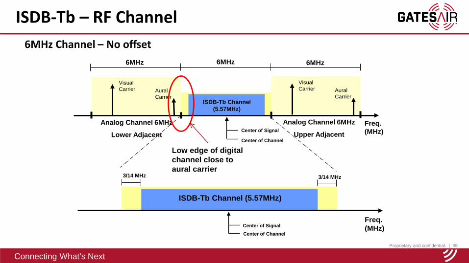
ISDB-Tb – RF Channel6MHz Channel – No offset
Visual Carrier Aural
Carrier
Analog Channel 6MHz
Lower Adjacent
Visual Carrier Aural
Carrier
Analog Channel 6MHz
Upper Adjacent
Freq. (MHz)
ISDB-Tb Channel (5.57MHz)
6MHz 6MHz 6MHz
Center of Signal
Center of Channel
Freq. (MHz)
ISDB-Tb Channel (5.57MHz)
Center of Signal
Center of Channel
3/14 MHz 3/14 MHz
Low edge of digital channel close to aural carrier
Proprietary and confidential. | 50
Connecting What’s Next
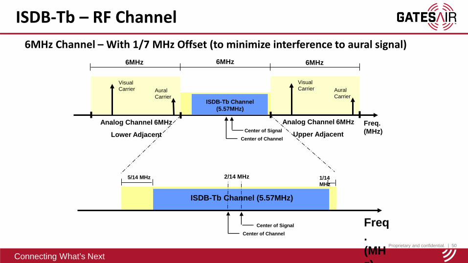
ISDB-Tb – RF Channel6MHz Channel – With 1/7 MHz Offset (to minimize interference to aural signal)
ISDB-Tb Channel (5.57MHz)
6MHz 6MHz 6MHz
Center of Signal
Center of Channel
Freq. (MHz)
ISDB-Tb Channel (5.57MHz)
Center of Signal
Center of Channel
5/14 MHz 1/14 MHz
2/14 MHz
Visual Carrier Aural
Carrier
Analog Channel 6MHz
Lower Adjacent
Visual Carrier Aural
Carrier
Analog Channel 6MHz
Upper Adjacent
Freq. (MHz)
Proprietary and confidential. | 51
Connecting What’s Next
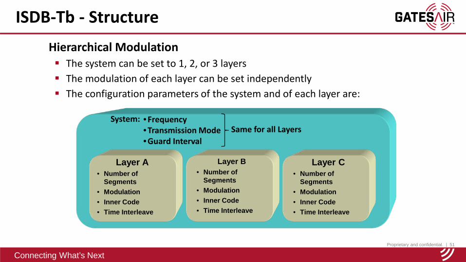
System: • Frequency• Transmission Mode• Guard Interval
Layer A• Number of
Segments• Modulation• Inner Code• Time Interleave
Layer B• Number of
Segments• Modulation• Inner Code• Time Interleave
ISDB-Tb - StructureHierarchical Modulation The system can be set to 1, 2, or 3 layers The modulation of each layer can be set independently The configuration parameters of the system and of each layer are:
Layer C• Number of
Segments• Modulation• Inner Code• Time Interleave
Same for all Layers
Proprietary and confidential. | 52
Connecting What’s Next
ISDB-Tb - Structure
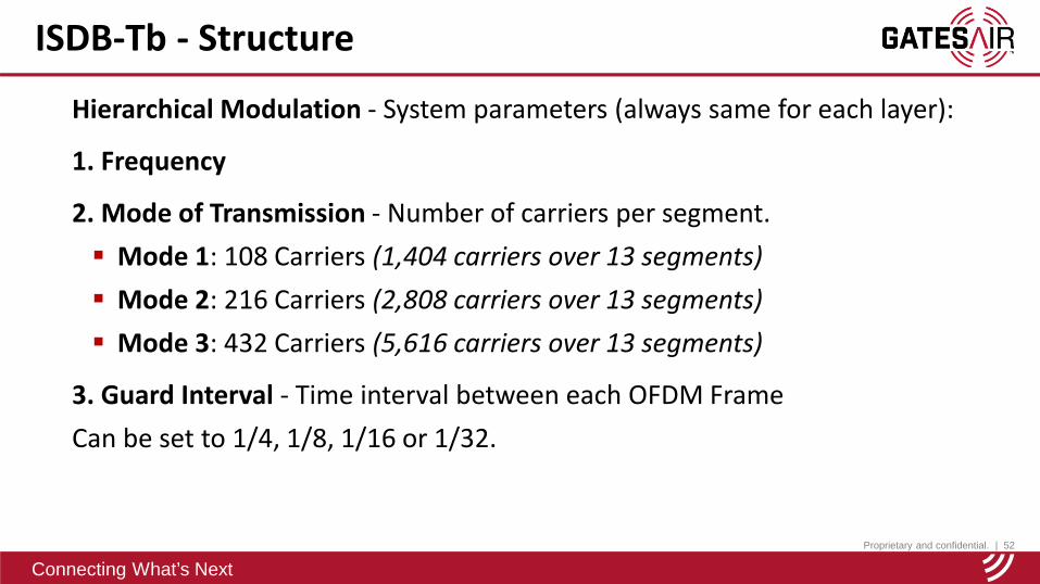
Hierarchical Modulation - System parameters (always same for each layer):
1. Frequency
2. Mode of Transmission - Number of carriers per segment. Mode 1: 108 Carriers (1,404 carriers over 13 segments) Mode 2: 216 Carriers (2,808 carriers over 13 segments) Mode 3: 432 Carriers (5,616 carriers over 13 segments)
3. Guard Interval - Time interval between each OFDM FrameCan be set to 1/4, 1/8, 1/16 or 1/32.
Proprietary and confidential. | 53
Connecting What’s Next
ISDB-Tb - Structure
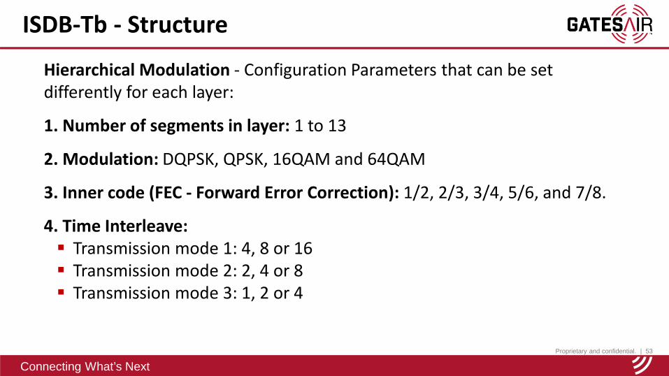
Hierarchical Modulation - Configuration Parameters that can be set differently for each layer:
1. Number of segments in layer: 1 to 13
2. Modulation: DQPSK, QPSK, 16QAM and 64QAM
3. Inner code (FEC - Forward Error Correction): 1/2, 2/3, 3/4, 5/6, and 7/8.
4. Time Interleave: Transmission mode 1: 4, 8 or 16 Transmission mode 2: 2, 4 or 8 Transmission mode 3: 1, 2 or 4

Proprietary and confidential. | 54
Connecting What’s Next
ISDB-Tb - Structure
Example # 1 – Hierarchical Modulation – 3 Layers
System: Frequency: 545,142857MHzTransmission Mode: 3Guard Interval: 1/8
Layer ANo. of Segments: 1Modulation: QPSKInner Code: 2/3Time Interleave: 4
Mobile Program: 400Kbps
Layer BNo. of Segments: 8Modulation: 64QAMInner Code: 3/4Time Interleave: 4
HD Program: 11.2Mbps
Layer CNo. of Segments: 4Modulation: 16QAMInner Code: 7/8Time Interleave: 4
SD Program: 4.3Mbps

Proprietary and confidential. | 55
Connecting What’s Next
ISDB-Tb - Structure
Example # 1 – Maximum Data Rate per SegmentLayer A - QPSK, 2/3
1 Segment - 400Kbps
Maximum: 416.08kbps
Layer B – 64QAM, 3/4
8 Segments – 11.2Mbps
Maximum: 8 x 1404.29 = 11.23Mbps
Layer C – 16QAM, 7/8
4 Segments – 4.3Mbps
Maximum: 4 x 1092.22 = 4.37Mbps
Modulation
Data Rate kbpsNumber of TSP
transmitted per segment (Mode 1/2/3)
Code Rate
GI 1/4 GI 1/8 GI 1/16 GI 1/32
Proprietary and confidential. | 56
Connecting What’s Next
ISDB-Tb - Structure
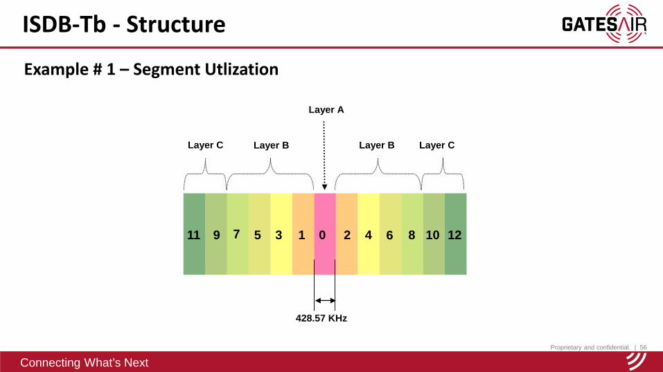
Example # 1 – Segment Utlization
11 29 7 5 3 1 0 4 6 8 10 12
428.57 KHz
Layer A
Layer C Layer CLayer BLayer B
Proprietary and confidential. | 57
Connecting What’s Next
ISDB-Tb - Structure
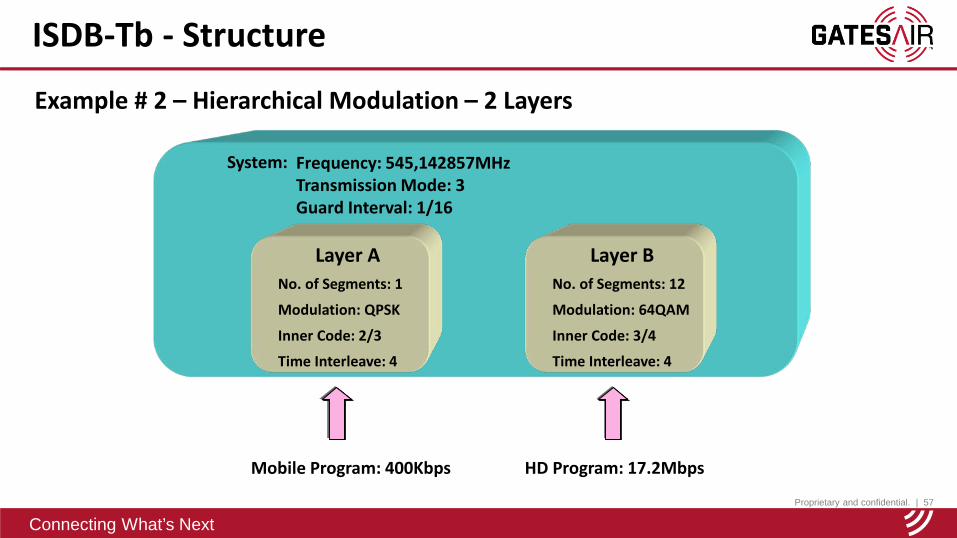
Example # 2 – Hierarchical Modulation – 2 Layers
System: Frequency: 545,142857MHzTransmission Mode: 3Guard Interval: 1/16
Layer ANo. of Segments: 1
Modulation: QPSK
Inner Code: 2/3
Time Interleave: 4
Mobile Program: 400Kbps
Layer BNo. of Segments: 12
Modulation: 64QAM
Inner Code: 3/4
Time Interleave: 4
HD Program: 17.2Mbps

Proprietary and confidential. | 58
Connecting What’s Next
ISDB-Tb - Structure
Example # 2 – Segment Utilization
11 29 7 5 3 1 0 4 6 8 10 12
428.57 KHz
Layer A
Layer BLayer B
Proprietary and confidential. | 59
Connecting What’s Next
ISDB-Tb - Structure
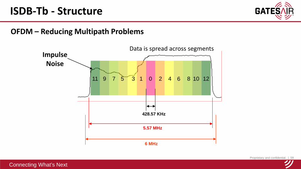
11 29 7 5 3 1 0 4 6 8 10 12
6 MHz
5.57 MHz
428.57 KHz
Impulse Noise
OFDM – Reducing Multipath Problems
Data is spread across segments
Proprietary and confidential. | 60
Connecting What’s Next
ISDB-Tb - Structure
TRANSMITTER
RF
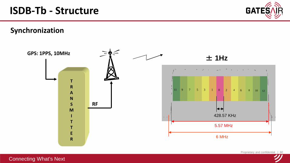
GPS: 1PPS, 10MHz
11 29 7 5 3 1 0 4 6 8 10 12
6 MHz
5.57 MHz
428.57 KHz
± 1Hz
Synchronization
Proprietary and confidential. | 61
Connecting What’s Next
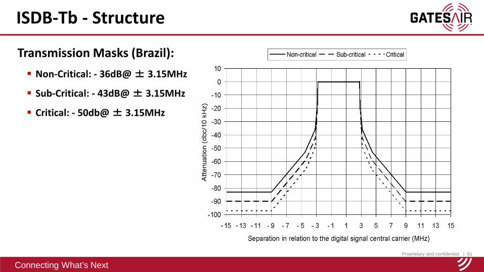
ISDB-Tb - Structure
Transmission Masks (Brazil): Non-Critical: - 36dB@ ± 3.15MHz
Sub-Critical: - 43dB@ ± 3.15MHz
Critical: - 50db@ ± 3.15MHz
Proprietary and confidential. | 62
Connecting What’s Next
ISDB-Tb - Structure
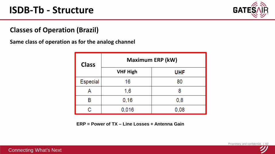
Classes of Operation (Brazil)Same class of operation as for the analog channel
ERP = Power of TX – Line Losses + Antenna Gain
Maximum ERP (kW)
VHF HighClass
Proprietary and confidential. | 63
Connecting What’s Next
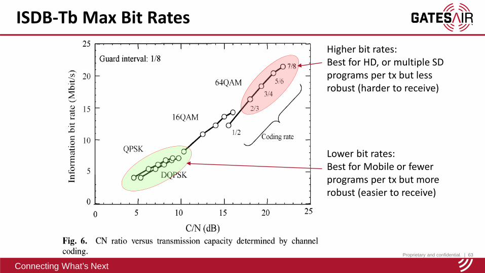
ISDB-Tb Max Bit RatesHigher bit rates:Best for HD, or multiple SD programs per tx but less robust (harder to receive)
Lower bit rates:Best for Mobile or fewer programs per tx but more robust (easier to receive)
Proprietary and confidential. | 64
Connecting What’s Next
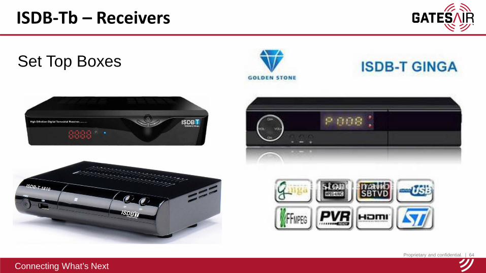
ISDB-Tb – Receivers
Set Top Boxes
Proprietary and confidential. | 65
Connecting What’s Next
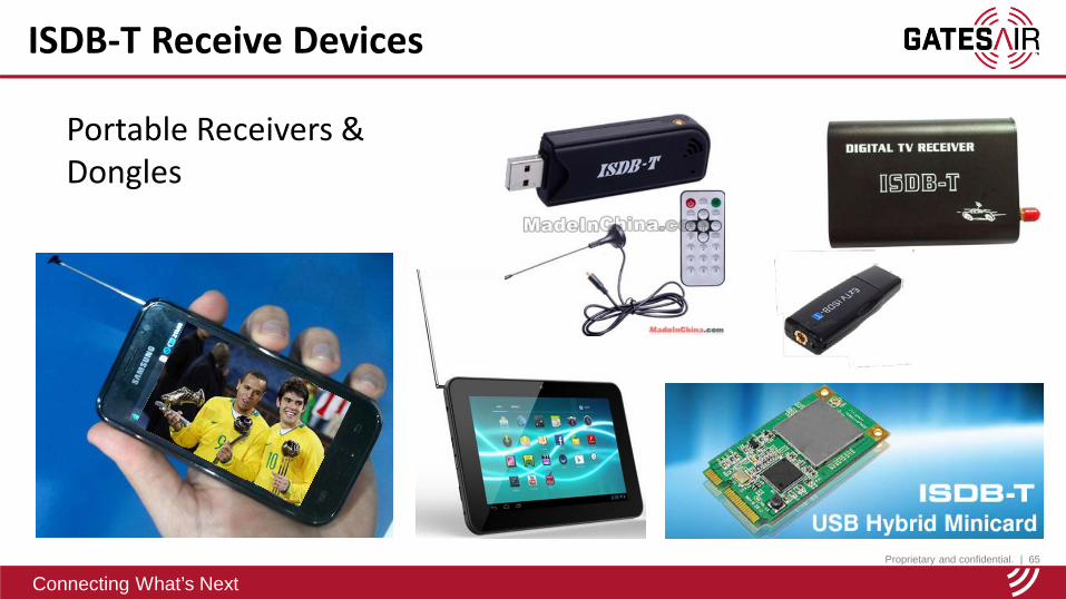
ISDB-T Receive Devices
Portable Receivers & Dongles
Proprietary and confidential. | 66
Connecting What’s Next
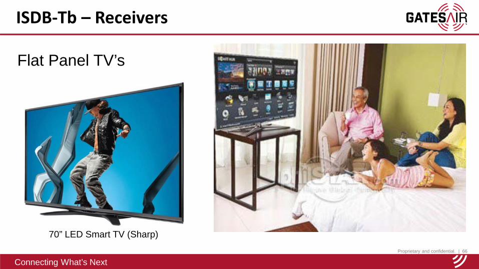
ISDB-Tb – Receivers
Flat Panel TV’s
70” LED Smart TV (Sharp)
Proprietary and confidential. | 67
Connecting What’s Next
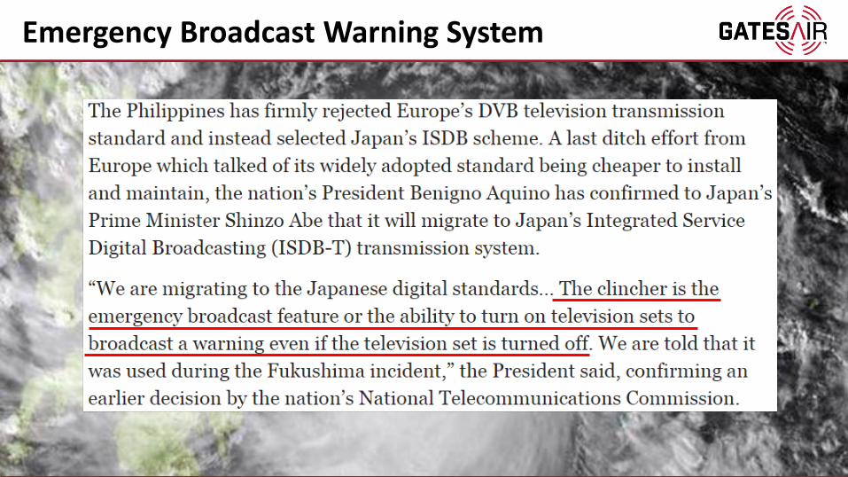
Emergency Broadcast Warning System
Proprietary and confidential. | 68
Connecting What’s Next
Connecting What’s Next
ISDB-TSingle Frequency Network(SFN) and GatesAir Solution
Mayon Volcano, Albay Povince, Philippines
Proprietary and confidential. | 69
Connecting What’s Next
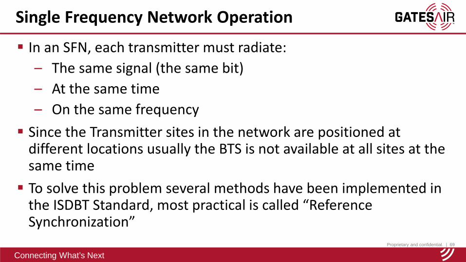
In an SFN, each transmitter must radiate:– The same signal (the same bit)– At the same time– On the same frequency
Since the Transmitter sites in the network are positioned at different locations usually the BTS is not available at all sites at the same time To solve this problem several methods have been implemented in
the ISDBT Standard, most practical is called “Reference Synchronization”
Single Frequency Network Operation
Proprietary and confidential. | 70
Connecting What’s Next
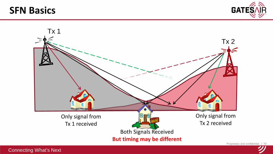
SFN Basics
Only signal from Tx 1 received
Tx 1
Tx 2
Only signal from Tx 2 received
Both Signals ReceivedBut timing may be different
Proprietary and confidential. | 71
Connecting What’s Next
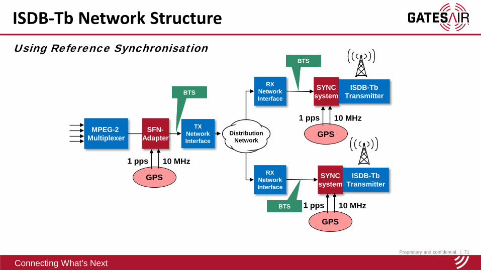
ISDB-Tb Network Structure
MPEG-2 Multiplexer
SYNCsystem
SFN-Adapter
GPS
1 pps 10 MHz
GPS
1 pps 10 MHz
SYNCsystem
GPS
1 pps 10 MHz
TXNetworkInterface
RXNetworkInterface
RXNetworkInterface
Using Reference Synchronisation
ISDB-Tb Transmitter
ISDB-Tb Transmitter
BTS
BTS
BTS
DistributionNetwork
Proprietary and confidential. | 72
Connecting What’s Next
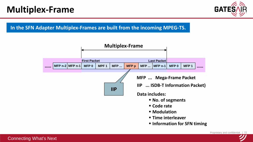
Multiplex-Frame
In the SFN Adapter Multiplex-Frames are built from the incoming MPEG-TS.
MFP 0 MPF 1 MFP ... MFP p MFP ... MFP n-1 MFP 0 MFP 1 .....First Packet Last Packet
Multiplex-Frame
MFP n-2 MFP n-1.....
MFP ... Mega-Frame PacketIIP ... ISDB-T Information Packet)
Data includes: No. of segments Code rate Modulation Time interleaver Information for SFN timing
IIP
Proprietary and confidential. | 73
Connecting What’s Next
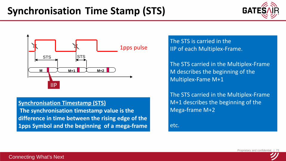
Synchronisation Time Stamp (STS)
Synchronisation Timestamp (STS) The synchronisation timestamp value is the difference in time between the rising edge of the 1pps Symbol and the beginning of a mega-frame
1pps pulseSTS STS
M M+1 M+2
IIP
The STS is carried in the IIP of each Multiplex-Frame.
The STS carried in the Multiplex-Frame M describes the beginning of the Multiplex-Fame M+1
The STS carried in the Multiplex-Frame M+1 describes the beginning of the Mega-frame M+2
etc.

Proprietary and confidential. | 74
Connecting What’s Next
TXNetworkAdapter
RXNetworkAdapter
DistributionNetwork
SYNCsystem
MPEG-2 Multiplexer
SFN-Adapter
ISDB-TbTransmitter
GPS
1 pps 10 MHz
GPS
1 pps 10 MHz
Maximum delay
Maximum delay: (reference synchronisation)The maximum delay describes the difference in time between a specific Multiplex-Frame leaving the SFN adapter and the corresponding COFDM Mega-frame available at the antenna output of each Transmitter in the SFN.
The maximum delay is a value adjustable in the SFN-Adapter. The set value has to be always higher than the longest actual network delay. The value is transported in each IIP
Maximum Network Delay
Proprietary and confidential. | 75
Connecting What’s Next
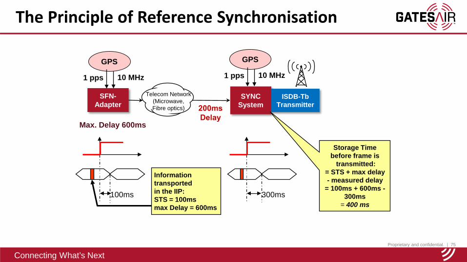
The Principle of Reference Synchronisation
Telecom Network(Microwave, Fibre optics)
SFN-Adapter
SYNCSystem
Max. Delay 600ms
100ms 300ms
Information transported in the IIP:STS = 100msmax Delay = 600ms
ISDB-Tb Transmitter
Storage Time before frame is
transmitted:= STS + max delay - measured delay
= 100ms + 600ms -300ms
= 400 ms
GPS
1 pps 10 MHz
GPS
1 pps 10 MHz
Proprietary and confidential. | 76
Connecting What’s Next
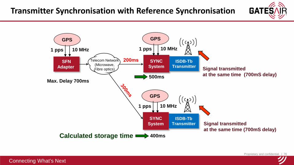
Transmitter Synchronisation with Reference Synchronisation
Telecom Network(Microwave, Fibre optics)
SFNAdapter
Max. Delay 700ms500ms
400ms
Signal transmittedat the same time (700mS delay)
Calculated storage time
SYNCSystem
ISDB-Tb Transmitter
GPS
1 pps 10 MHz
GPS
1 pps 10 MHz
SYNCSystem
ISDB-Tb Transmitter
GPS
1 pps 10 MHz
Signal transmittedat the same time (700mS delay)
Proprietary and confidential. | 77
Connecting What’s Next
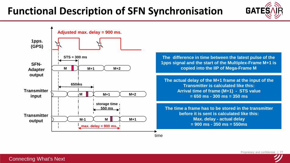
Functional Description of SFN Synchronisation
The time a frame has to be stored in the transmitter before it is sent is calculated like this:
Max. delay - actual delay= 900 ms - 350 ms = 550ms
The actual delay of the M+1 frame at the input of the Transmitter is calculated like this:
Arrival time of frame (M+1) - STS value = 650 ms - 300 ms = 350 ms
time
M M+1 M+2
650ms
SFN-Adapteroutput
Transmitterinput
1pps.(GPS)
Transmitteroutput
Adjusted max. delay = 900 ms.
The difference in time between the latest pulse of the 1pps signal and the start of the Multiplex-Frame M+1 is
copied into the IIP of Mega-Frame M
M M+1 M+2
max. delay = 900 ms.
M+1M-1 M
STS = 300 ms
storage time550 ms
Proprietary and confidential. | 78
Connecting What’s Next
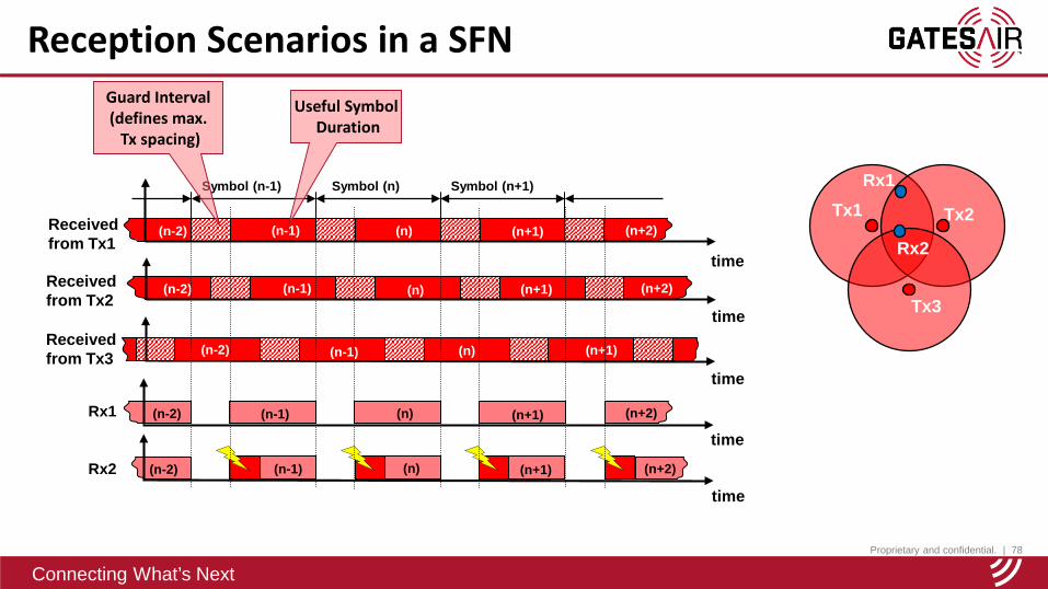
Reception Scenarios in a SFN
Symbol (n-1) Symbol (n) Symbol (n+1)
time
(n+1) (n+2)(n)(n-1)(n-2)
time
(n-1) (n) (n+1) (n+2)(n-2)Rx1
(n) (n+1) (n+2)(n-1)(n-2)Rx2
time
Guard Interval(defines max.
Tx spacing)
Useful SymbolDuration
(n-1) (n) (n+1)
time
(n-2) (n+2)
Receivedfrom Tx1
Receivedfrom Tx2
time
(n-2) (n-1) (n) (n+1)Receivedfrom Tx3
Tx1 Tx2
Tx3
Rx1
Rx2
Proprietary and confidential. | 79
Connecting What’s Next
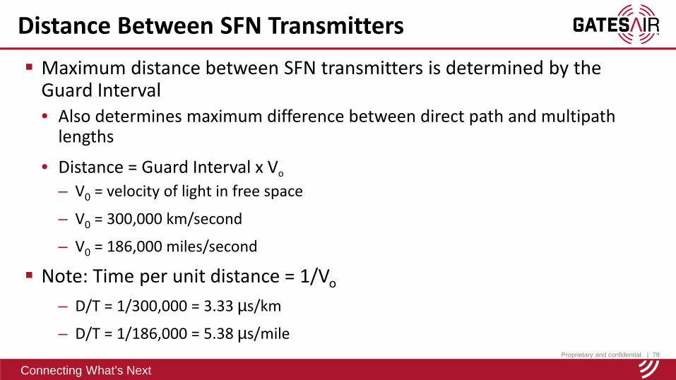
Maximum distance between SFN transmitters is determined by the Guard Interval• Also determines maximum difference between direct path and multipath
lengths
• Distance = Guard Interval x Vo
– V0 = velocity of light in free space
– V0 = 300,000 km/second
– V0 = 186,000 miles/second
Note: Time per unit distance = 1/Vo
– D/T = 1/300,000 = 3.33 µs/km
– D/T = 1/186,000 = 5.38 µs/mile
Distance Between SFN Transmitters
Proprietary and confidential. | 80
Connecting What’s Next
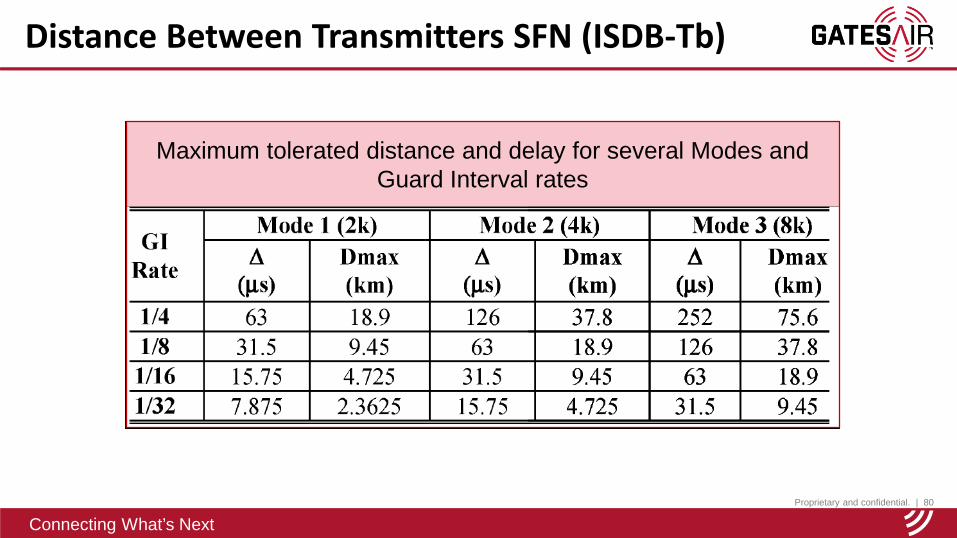
Distance Between Transmitters SFN (ISDB-Tb)
Maximum tolerated distance and delay for several Modes and Guard Interval rates
Proprietary and confidential. | 82
Connecting What’s Next
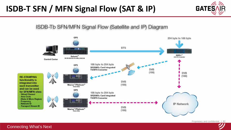
ISDB-T SFN / MFN Signal Flow (SAT & IP)

Proprietary and confidential. | 83
Connecting What’s Next
ASI-IP and Satellite Rx Modules
Space for Optional Modules
Satellite Receiver/Decoder Module(SRD, SRZ)
ASI over IP Module(IPA / IPZ)
Rear of Apex M2X, UAXT, or UAX Compact Series Tx
Proprietary and confidential. | 84
Connecting What’s Next
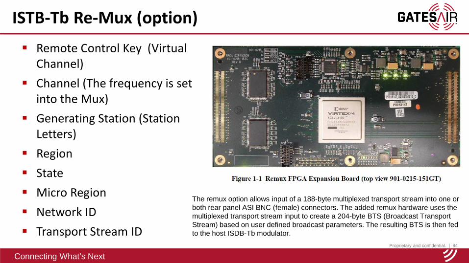
Remote Control Key (Virtual Channel)
Channel (The frequency is set into the Mux)
Generating Station (Station Letters)
Region State Micro Region Network ID Transport Stream ID
ISTB-Tb Re-Mux (option)
The remux option allows input of a 188-byte multiplexed transport stream into one or both rear panel ASI BNC (female) connectors. The added remux hardware uses the multiplexed transport stream input to create a 204-byte BTS (Broadcast Transport Stream) based on user defined broadcast parameters. The resulting BTS is then fed to the host ISDB-Tb modulator.
Proprietary and confidential. | 85
Connecting What’s Next
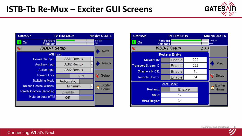
ISTB-Tb Re-Mux – Exciter GUI Screens
GatesAir TV TEM CH19 Maxiva ULXT-63.0 kW0%
GatesAir TV TEM CH19 Maxiva ULXT-63.0 kW0%
Proprietary and confidential. | 86
Connecting What’s Next
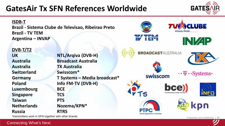
ISDB-TBrazil - Sistema Clube de Televisao, Ribeirao PretoBrazil - TV TEMArgentina – INVAP
DVB-T/T2UK NTL/Arqiva (DVB-H)Australia Broadcast Australia Australia TX AustraliaSwitzerland Swisscom*Germany T Systems – Media broadcast*Poland Info FM-TV (DVB-H)Luxembourg BCESingapore TCSTaiwan PTSNetherlands Nozema/KPN*Russia RTRS*transmitters work in SFN together with other brands
GatesAir Tx SFN References Worldwide
Proprietary and confidential. | 87
Connecting What’s Next
Connecting What’s Next
ISDB-T Coverage& Planning
Chocolate Hills, Bohol Province, Philippines

Proprietary and confidential. | 88
Connecting What’s Next
Propagation Models For Coverage Estimation Gaussian Channel
• The Gaussian channel is often used as a channel model in which the only impairment to communication is a linear addition of wideband or white noise with a constant spectral density (expressed as Watts per Hertz of bandwidth) and a Gaussian distribution of amplitude.
Ricean Fading Channel• Rician fading is a stochastic model for TV/Radio propagation anomalies caused by partial
cancellation of a TV/Radio signal by itself — the signal arrives at the receiver by several different paths (hence exhibiting multipath interference), and at least one of the paths is changing (lengthening or shortening). Rician fading occurs when one of the paths, typically a line of sight signal, is much stronger than the others.
Rayleigh Fading Channel• Rayleigh fading is viewed as a reasonable model for tropospheric and ionospheric signal
propagation as well as the effect of heavily built-up urban environments on radio signals. Rayleigh fading is most applicable when there is no dominant propagation along a line of sight between the transmitter and receiver.

Proprietary and confidential. | 89
Connecting What’s Next
Garden Weekly News 10
Gaussian Channel
Directly received Signal
Directional antenna used Direct reception
Directional receive antenna
Proprietary and confidential. | 90
Connecting What’s Next
Garden Weekly News 10
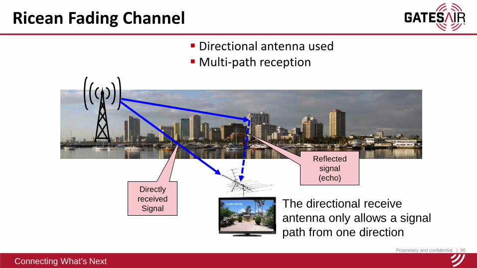
Ricean Fading Channel
Directly received Signal
Directional antenna usedMulti-path reception
The directional receive antenna only allows a signal path from one direction
Reflected signal(echo)

Proprietary and confidential. | 91
Connecting What’s Next
Garden Weekly News 10
Rayleigh Fading Channel Non-directional antenna usedMulti-path reception No direct path reception
The non-directional receive antenna allows multi-path from multiple directions
Reflected signal
(echoes)
Reflected signal
(echoes)
No direct line of sight between tx
and receiver.
Proprietary and confidential. | 92
Connecting What’s Next
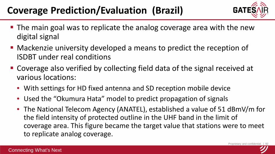
Coverage Prediction/Evaluation (Brazil) The main goal was to replicate the analog coverage area with the new
digital signal Mackenzie university developed a means to predict the reception of
ISDBT under real conditions Coverage also verified by collecting field data of the signal received at
various locations:• With settings for HD fixed antenna and SD reception mobile device• Used the “Okumura Hata” model to predict propagation of signals• The National Telecom Agency (ANATEL), established a value of 51 dBmV/m for
the field intensity of protected outline in the UHF band in the limit of coverage area. This figure became the target value that stations were to meet to replicate analog coverage.
Proprietary and confidential. | 93
Connecting What’s Next
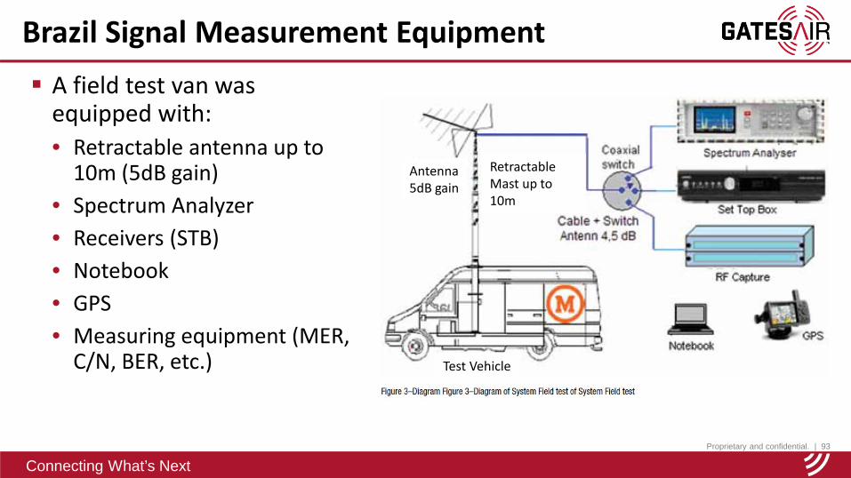
Brazil Signal Measurement Equipment A field test van was
equipped with:• Retractable antenna up to
10m (5dB gain)• Spectrum Analyzer• Receivers (STB)• Notebook• GPS• Measuring equipment (MER,
C/N, BER, etc.) Test Vehicle
RetractableMast up to 10m
Antenna5dB gain

Proprietary and confidential. | 94
Connecting What’s Next
Measured signal strength vs. predicted
ISDB-T/TbISDB-T/Tb network coverage planning
Lichtenau, Germany
Proprietary and confidential. | 96
Connecting What’s Next
Copyright (c) 2015 by LS telcom AG
This document must neither be copied wholly or partly, nor published or re-sold without prior written permission of LStelcom. The information contained in this document is proprietary to LS telcom. The information shall only serve fordocumentation purposes or as support for education and training purposes and for the operation and maintenance of LStelcom software. It must be treated strictly confidential and must neither be disclosed to any third party nor be used forother purposes, e.g. software development, without the written consent of LS telcom.This document may contain product names, e. g. MS Windows, MS Word, MS Excel and MS Access, which areprotected by copyright or registered trademarks / brand names in favour of their respective owners.LS telcom makes no warranty or representation relating to this document and the information contained herein. LStelcom is not responsible for any costs incurred as a result of the use of this document and the information containedherein, including but not limited to, lost profits or revenue, loss of data, costs of recreating data, the cost of any substituteequipment or program, or claims by any third party.
Disclaimer
Proprietary and confidential. | 97
Connecting What’s Next
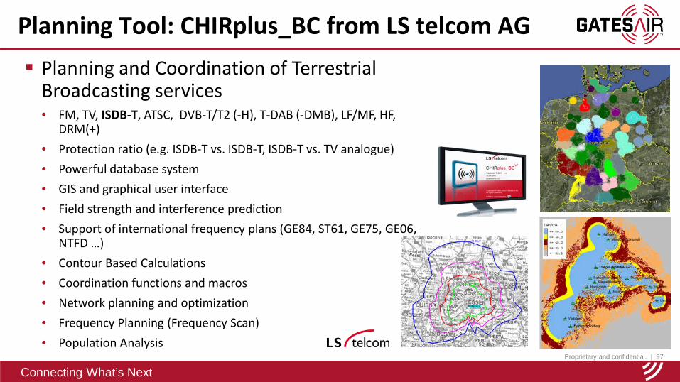
Planning and Coordination of Terrestrial Broadcasting services• FM, TV, ISDB-T, ATSC, DVB-T/T2 (-H), T-DAB (-DMB), LF/MF, HF,
DRM(+)• Protection ratio (e.g. ISDB-T vs. ISDB-T, ISDB-T vs. TV analogue)• Powerful database system• GIS and graphical user interface• Field strength and interference prediction• Support of international frequency plans (GE84, ST61, GE75, GE06,
NTFD …)• Contour Based Calculations • Coordination functions and macros• Network planning and optimization• Frequency Planning (Frequency Scan)• Population Analysis
Planning Tool: CHIRplus_BC from LS telcom AG

Proprietary and confidential. | 98
Connecting What’s Next
Planning Parameter – TX data Transmitter data quality
Proprietary and confidential. | 99
Connecting What’s Next
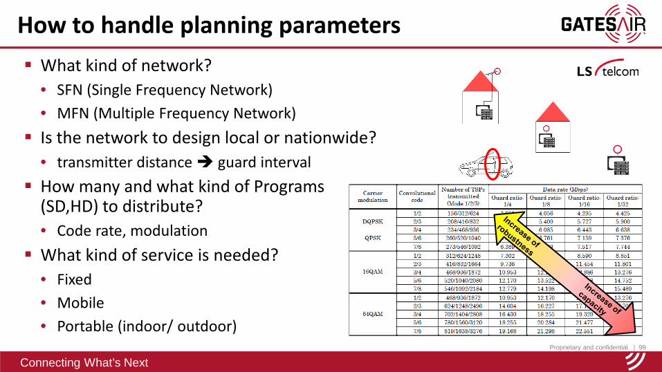
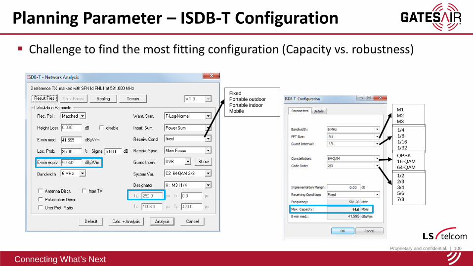
How to handle planning parameters What kind of network?
• SFN (Single Frequency Network)• MFN (Multiple Frequency Network)
Is the network to design local or nationwide?• transmitter distance guard interval
How many and what kind of Programs (SD,HD) to distribute?• Code rate, modulation
What kind of service is needed?• Fixed• Mobile• Portable (indoor/ outdoor)
Proprietary and confidential. | 100
Connecting What’s Next
M1M2M3
1/41/81/161/32
QPSK16-QAM64-QAM
1/22/33/45/67/8
FixedPortable outdoorPortable indoorMobile
Challenge to find the most fitting configuration (Capacity vs. robustness)
Planning Parameter – ISDB-T Configuration
Proprietary and confidential. | 101
Connecting What’s Next
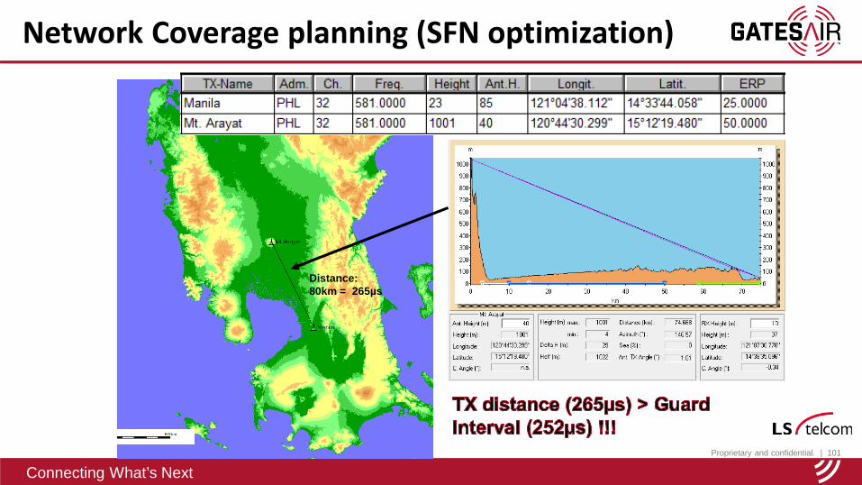
Distance: 80km = 265µs
Network Coverage planning (SFN optimization)
Proprietary and confidential. | 102
Connecting What’s Next
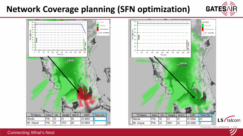
Network Coverage planning (SFN optimization)
Proprietary and confidential. | 103
Connecting What’s Next
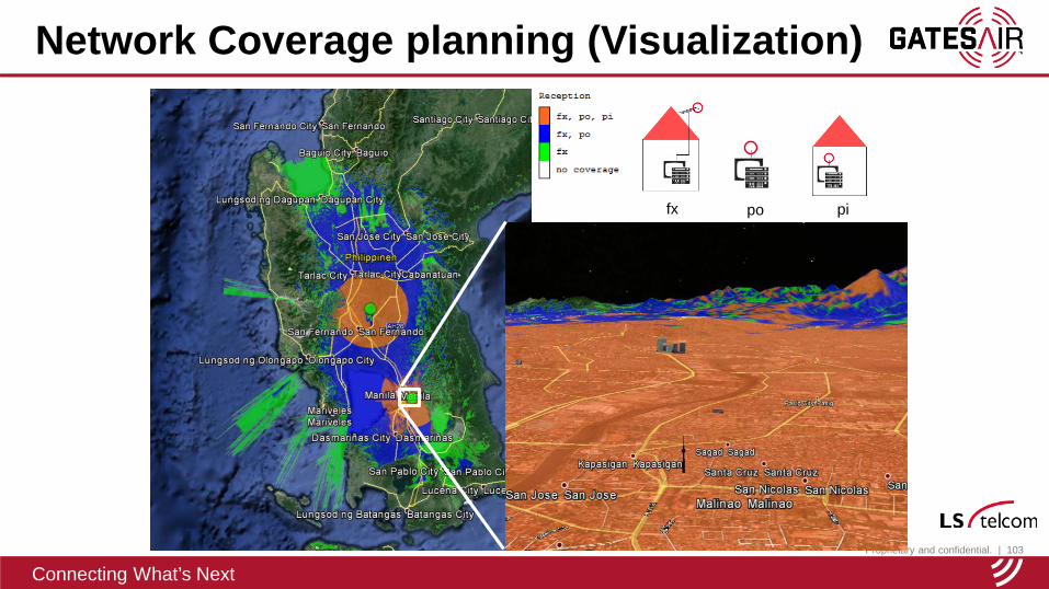
Network Coverage planning (Visualization)
fx po pi
Proprietary and confidential. | 104
Connecting What’s Next
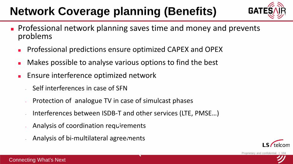
Professional network planning saves time and money and prevents problems Professional predictions ensure optimized CAPEX and OPEX
Makes possible to analyse various options to find the best
Ensure interference optimized network- Self interferences in case of SFN
- Protection of analogue TV in case of simulcast phases
- Interferences between ISDB-T and other services (LTE, PMSE…)
- Analysis of coordination requirements
- Analysis of bi-multilateral agreements
Network Coverage planning (Benefits)
Proprietary and confidential. | 105
Connecting What’s Next
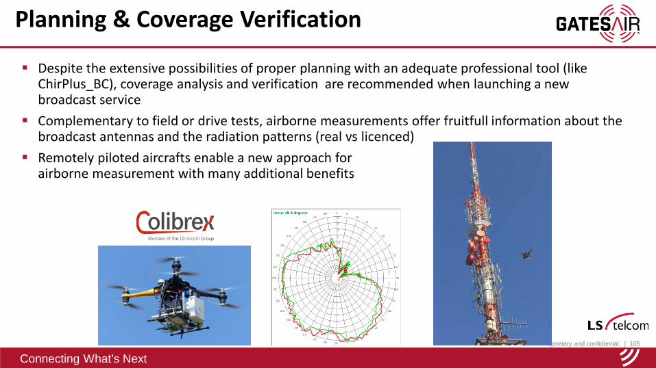
Planning & Coverage Verification
Despite the extensive possibilities of proper planning with an adequate professional tool (like ChirPlus_BC), coverage analysis and verification are recommended when launching a new broadcast service
Complementary to field or drive tests, airborne measurements offer fruitfull information about the broadcast antennas and the radiation patterns (real vs licenced)
Remotely piloted aircrafts enable a new approach for airborne measurement with many additional benefits
Proprietary and confidential. | 106
Connecting What’s Next
Your Contacts at LS telcom
LS telcom AGMilos PavlovicSales Manager BroadcastIm Gewerbegebiet 31-33D-77839 Lichtenau
Phone: +49 7227 9535-493Mobile: +49 172 7471-734e-mail: [email protected]
Colibrex GmbH (LS telcom Group)Luc HaeberléManaging DirectorVictoria Boulevard B 109D-77836 Rheinmünster
Phone: +49 7227 9535-921Mobile: +49 172 2008668e-mail: [email protected] / www.LStelcom.com
Proprietary and confidential. | 107
Connecting What’s Next
Connecting What’s Next
New High-Efficiency Transmitters For
Proprietary and confidential. | 108
Connecting What’s Next108
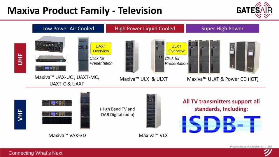
Maxiva Product Family - TelevisionU
HF
Super High Power
Maxiva™ ULXT & Power CD (IOT)Maxiva™ ULX & ULXTMaxiva™ UAX-UC , UAXT-MC, UAXT-C & UAXT
Low Power Air Cooled High Power Liquid CooledVH
F
Maxiva™ VLXMaxiva™ VAX-3D
(High Band TV andDAB Digital radio)
All TV transmitters support all standards, Including:
ULXT Overview
UAXT Overview
Click for Presentation
Click for Presentation
Proprietary and confidential. | 109
Connecting What’s Next
Connecting What’s Next
GA experience and Site References for ISDB-T Deployments
Proprietary and confidential. | 110
Connecting What’s Next110
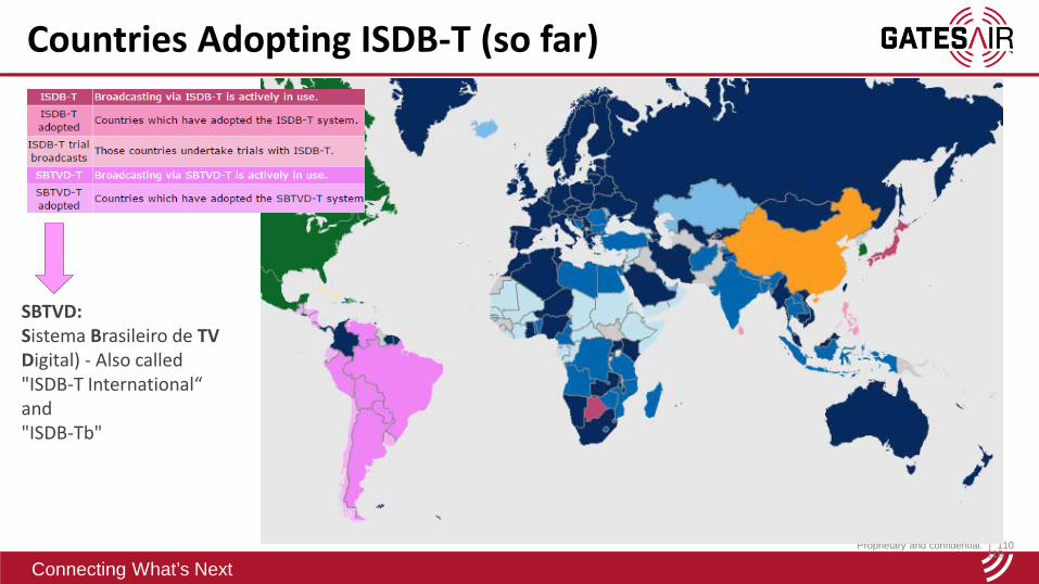
Countries Adopting ISDB-T (so far)
SBTVD: Sistema Brasileiro de TVDigital) - Also called"ISDB-T International“and"ISDB-Tb"
Proprietary and confidential. | 111
Connecting What’s Next
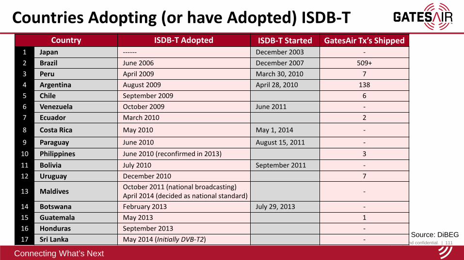
Countries Adopting (or have Adopted) ISDB-TCountry ISDB-T Adopted ISDB-T Started GatesAir Tx’s Shipped
1 Japan ------ December 2003 -2 Brazil June 2006 December 2007 509+3 Peru April 2009 March 30, 2010 74 Argentina August 2009 April 28, 2010 1385 Chile September 2009 66 Venezuela October 2009 June 2011 -7 Ecuador March 2010 2
8 Costa Rica May 2010 May 1, 2014 -
9 Paraguay June 2010 August 15, 2011 -10 Philippines June 2010 (reconfirmed in 2013) 311 Bolivia July 2010 September 2011 -12 Uruguay December 2010 7
13 Maldives October 2011 (national broadcasting)April 2014 (decided as national standard) -
14 Botswana February 2013 July 29, 2013 -15 Guatemala May 2013 116 Honduras September 2013 -17 Sri Lanka May 2014 (Initially DVB-T2) - Source: DiBEG
Proprietary and confidential. | 112
Connecting What’s Next
ANALOG
ATSC
DVB-TDVB-H
DVB-T2
ISDBTFLO
CTTB
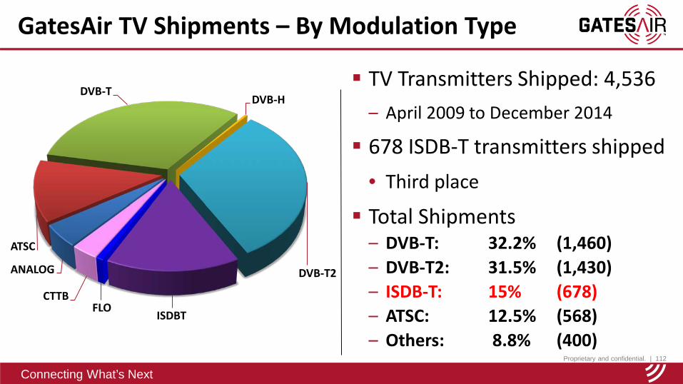
TV Transmitters Shipped: 4,536– April 2009 to December 2014
678 ISDB-T transmitters shipped• Third place
Total Shipments– DVB-T: 32.2% (1,460)– DVB-T2: 31.5% (1,430)– ISDB-T: 15% (678)– ATSC: 12.5% (568)– Others: 8.8% (400)
GatesAir TV Shipments – By Modulation Type
Proprietary and confidential. | 113
Connecting What’s Next
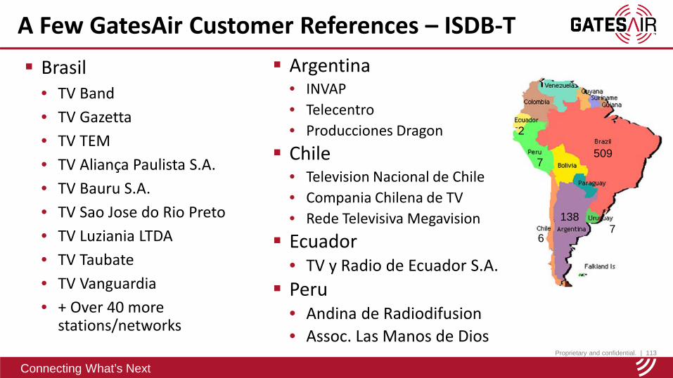
Brasil• TV Band• TV Gazetta• TV TEM• TV Aliança Paulista S.A.• TV Bauru S.A.• TV Sao Jose do Rio Preto• TV Luziania LTDA• TV Taubate• TV Vanguardia• + Over 40 more
stations/networks
A Few GatesAir Customer References – ISDB-T Argentina
• INVAP• Telecentro• Producciones Dragon Chile
• Television Nacional de Chile• Compania Chilena de TV• Rede Televisiva Megavision Ecuador
• TV y Radio de Ecuador S.A. Peru
• Andina de Radiodifusion• Assoc. Las Manos de Dios
509
138
6
7
2
7

Proprietary and confidential. | 114
Connecting What’s Next
Case Study – TV TEM, Brazil
Background information:• TV TEM is a major Rede Globo affiliate in Brazil: 318 cities in São
Paulo state– Project – to increase coverage to 8 million viewers
Why they chose GatesAir:• Met stringent technical requirements• GatesAir guaranteed that the SFN will work flawlessly• Competitive commercial package• Excellent pre- and post-sales support• A excellent long-term customer relationship – repeat buyer!
Anchor products:• Maxiva ULX, UAX, high-efficiency ULXT

Proprietary and confidential. | 115
Connecting What’s Next
Connecting What’s Next
Challenges and Lessons Learned
Super Typhoon Haiyan

Proprietary and confidential. | 116
Connecting What’s Next
A lot of testing and planning was done before the roll out of ISDB-T Field tests conducted in Rio de Janeiro to test the robustness of the 1-
Seg mobile system Public awareness was key to the success
• By 2012 there were DTV transmissions in 433 municipalities across Brazil• Coverage to almost 45.5% of the population Analog switch-off plans for Brazil
• Analog shut down in 2 cities – April 3rd, 2016 (Brasilia and Rio verde)• Four more cities will shut off analog by end of 2016• Entire country shuts off analog by end of 2018
Brazil Experience
Proprietary and confidential. | 117
Connecting What’s Next
Coverage planning was a good approximation…. However, there were “holes” in the coverage areas with received signals
below the predicted levels• Some additional low power transmitters, transposers, or on-channel gap
fillers were needed to reduce these coverage gaps Many early receivers and STB’s did not correctly apply tables (Like PID,
PAT, etc.)• This resulted in receivers not having correct channel or program information• If a broadcaster made changes, added a program, etc. the receiver did not
recognize this unless all channels were re-scanned Early STB’s and receivers were very expensive but prices have since
greatly reduced• Limited affordability for early viewers of ISDB-T
Lessons Learned (Brazil)
Proprietary and confidential. | 118
Connecting What’s Next
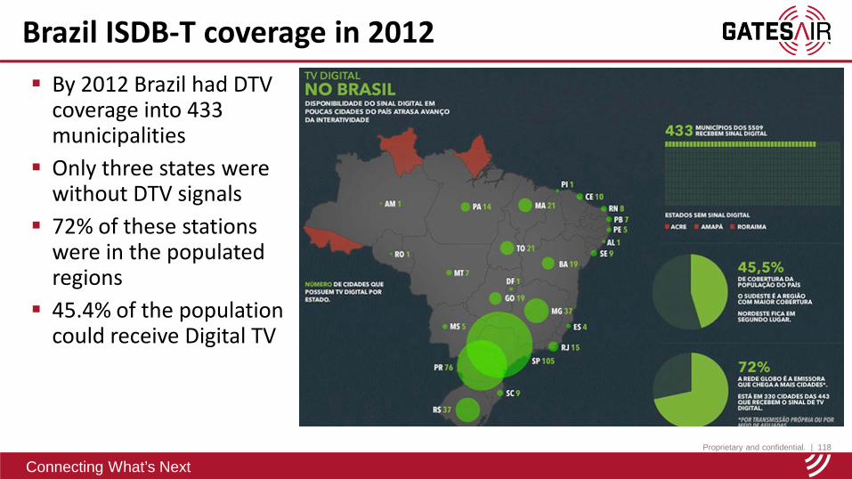
By 2012 Brazil had DTV coverage into 433 municipalities
Only three states were without DTV signals
72% of these stations were in the populated regions
45.4% of the population could receive Digital TV
Brazil ISDB-T coverage in 2012

Proprietary and confidential. | 119
Connecting What’s Next
Connecting What’s Next
The End –Questions?
Martyn HorspoolGatesAir El Nido, Palawan, Philippines