Embed Size (px)
Citation preview

MARCH 14, 2009 Telecom Engineering Research Lab, INHA University, Korea S.M.R. Islam
Channel Estimation Techniques Based on Pilot Arrangement in OFDM Systems
Authors: Sinem Coleri, Mustafa Ergen
MARCH 14, 2009 Telecom Engineering Research Lab, INHA University, Korea S.M.R. Islam
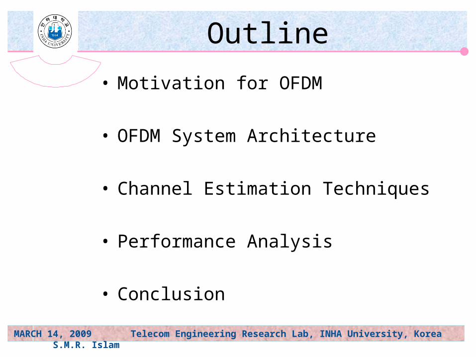
Outline
• Motivation for OFDM
• OFDM System Architecture
• Channel Estimation Techniques
• Performance Analysis
• Conclusion
MARCH 14, 2009 Telecom Engineering Research Lab, INHA University, Korea S.M.R. Islam
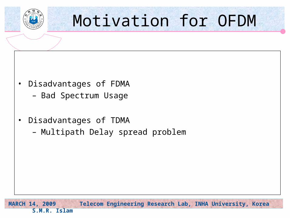
Motivation for OFDM
• Disadvantages of FDMA– Bad Spectrum Usage
• Disadvantages of TDMA– Multipath Delay spread problem
MARCH 14, 2009 Telecom Engineering Research Lab, INHA University, Korea S.M.R. Islam
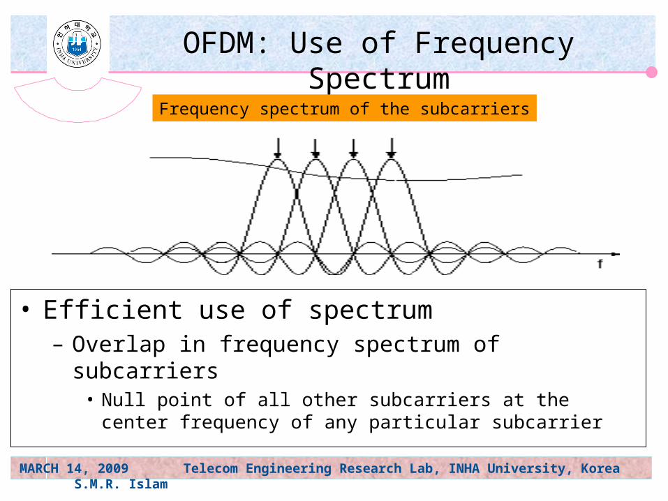
OFDM: Use of Frequency Spectrum
• Efficient use of spectrum– Overlap in frequency spectrum of subcarriers
• Null point of all other subcarriers at the center frequency of any particular subcarrier
Frequency spectrum of the subcarriers
MARCH 14, 2009 Telecom Engineering Research Lab, INHA University, Korea S.M.R. Islam
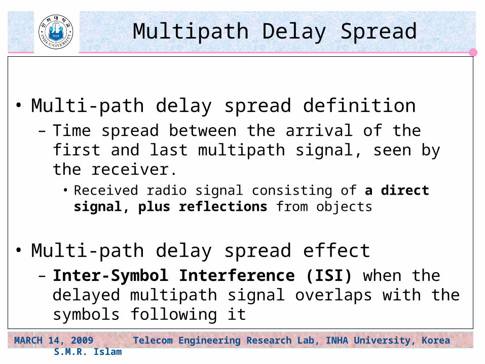
Multipath Delay Spread
• Multi-path delay spread definition– Time spread between the arrival of the first and last
multipath signal, seen by the receiver.• Received radio signal consisting of a direct signal, plus
reflections from objects
• Multi-path delay spread effect– Inter-Symbol Interference (ISI) when the delayed
multipath signal overlaps with the symbols following it
MARCH 14, 2009 Telecom Engineering Research Lab, INHA University, Korea S.M.R. Islam
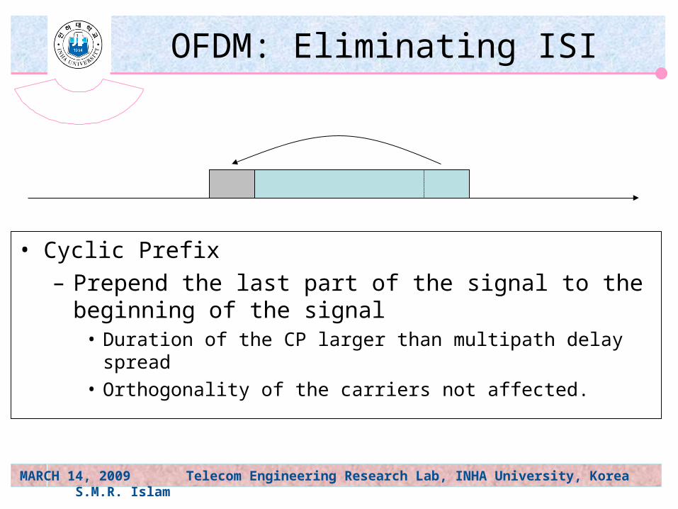
OFDM: Eliminating ISI
• Cyclic Prefix– Prepend the last part of the signal to the beginning of the
signal• Duration of the CP larger than multipath delay spread• Orthogonality of the carriers not affected.
MARCH 14, 2009 Telecom Engineering Research Lab, INHA University, Korea S.M.R. Islam
OFDM Overview
• Divides high-speed serial information signal into multiple lower-speed sub-signals.– Transmits simultaneously at different frequencies in
parallel.
• Modulation ( BPSK, PSK,QPSK,16QAM, …).
• Pilot subcarriers used to prevent frequency and phase shift errors.
MARCH 14, 2009 Telecom Engineering Research Lab, INHA University, Korea S.M.R. Islam
Benefits of OFDM
• Higher data rates– Overlap of subcarriers
• Lower bandwidth than spread spectrum.– High spectral efficiency
• Lower multi-path distortion– Usage of cyclic prefix
MARCH 14, 2009 Telecom Engineering Research Lab, INHA University, Korea S.M.R. Islam
Our OFDM System Assumptions
Usage of cyclic Prefix
Impulse response of the channel shorter than Cyclic Prefix.
Slow fading effects so that the channel is time-invariant over the symbol interval.
Rectangular Windowing of the transmitted pulses
Perfect Synchronization of transmitter and receiver
Additive, white, Gaussian channel noise

MARCH 14, 2009 Telecom Engineering Research Lab, INHA University, Korea S.M.R. Islam
System Architecture-1
MARCH 14, 2009 Telecom Engineering Research Lab, INHA University, Korea S.M.R. Islam
1,...,2,1,0
Nn
kXIDFTnx
1,...,1,0,
1,...,1,,
Nnnx
NNnnNxnx gg
f nwnhnxy ff
1,...,1,0 Nnnyny f
1,...,2,1,0
Nk
nyDFTkY
1,...,1,0
Nk
kWkIkHkXkY 1,...,1,0 NkkH
kYkX
ee
1
76
54
32
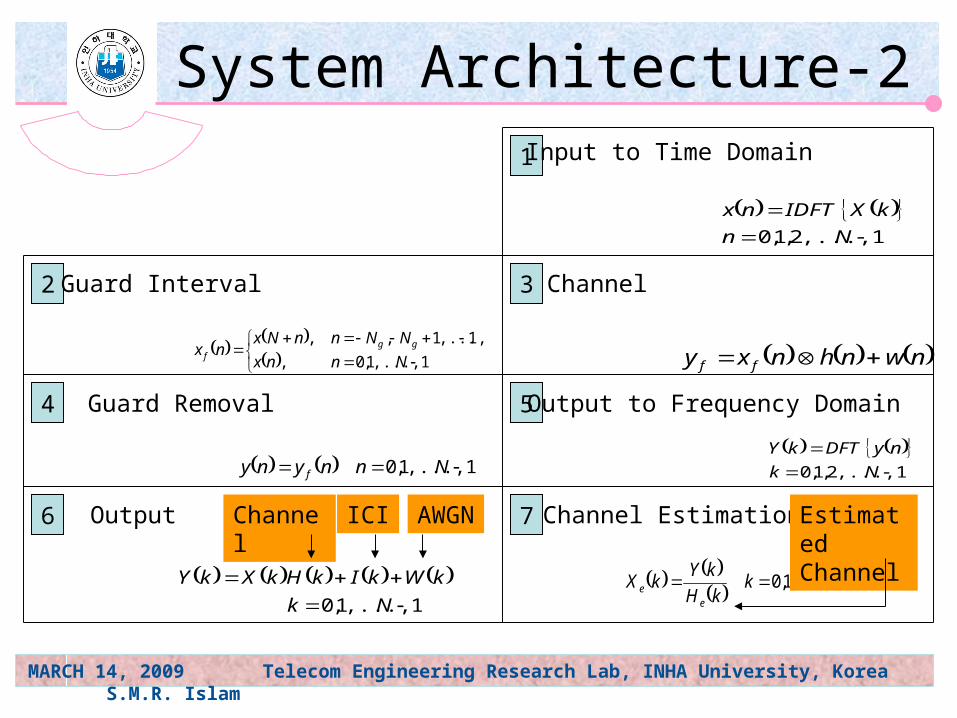
System Architecture-2Input to Time Domain
Guard Interval Channel
Guard Removal Output to Frequency Domain
Output Channel EstimationICI AWGNChannel Estimated Channel
MARCH 14, 2009 Telecom Engineering Research Lab, INHA University, Korea S.M.R. Islam
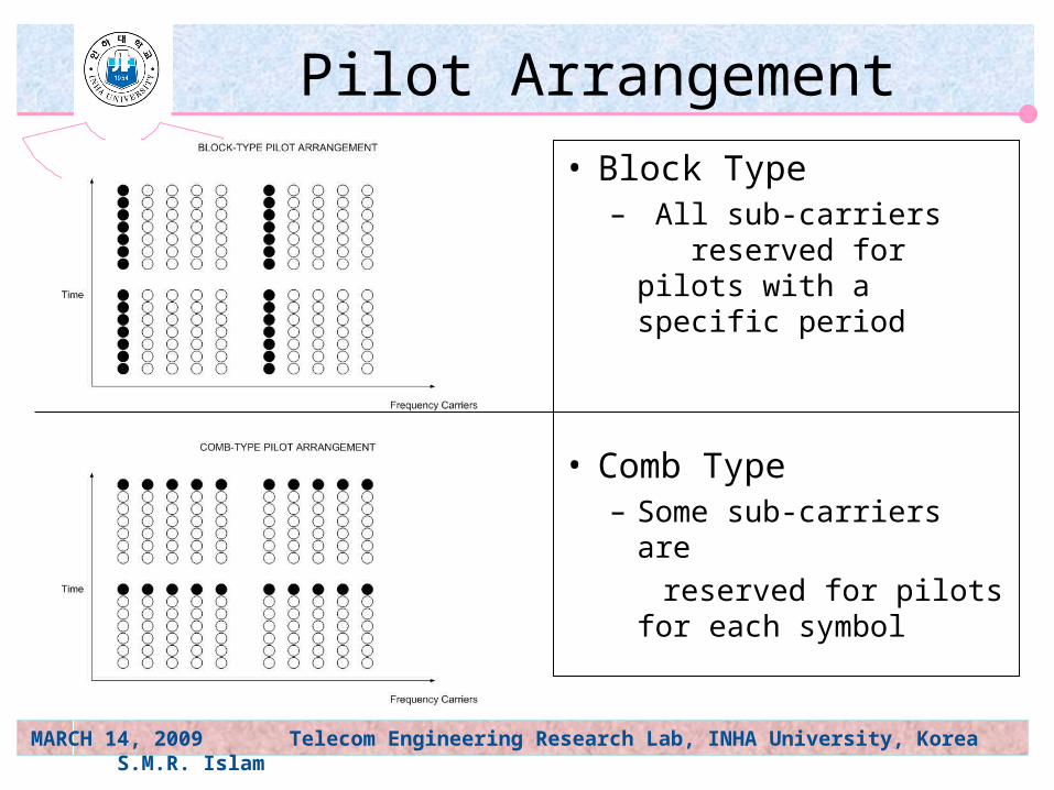
Pilot Arrangement
• Block Type– All sub-carriers
reserved for pilots with a specific period
• Comb Type– Some sub-carriers are
reserved for pilots for each symbol
MARCH 14, 2009 Telecom Engineering Research Lab, INHA University, Korea S.M.R. Islam
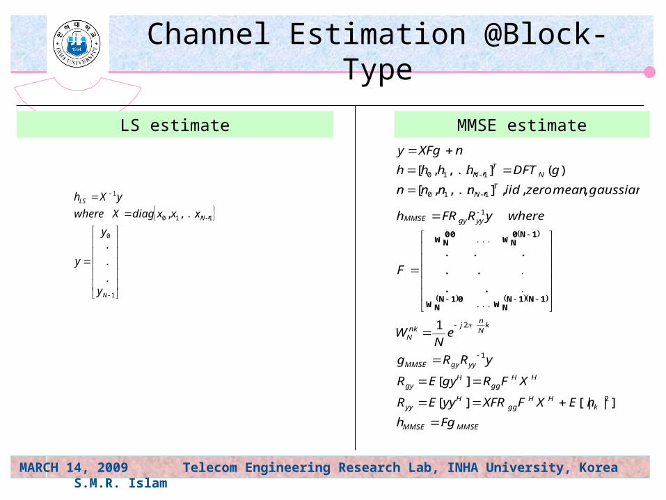
Channel Estimation @Block-Type
1
0
110
1
.
.
.
,...,,
N
N
LS
y
y
y
xxxdiagXwhere
yXh
LS estimate MMSE estimate
MMSEMMSE
kHH
ggH
yy
HHgg
Hgy
yygyMMSE
kN
nj
nkN
yygyMMSE
TN
NT
N
Fgh
nEXFXFRyyER
XFRgyER
yRRg
eN
W
F
whereyRFRh
gaussianmeanzeroiidnnnn
gDFThhhh
nXFgy
]|[|][
][
1
.
.
.
.
.
.
.
,,,],...,,[
)(],...,,[
2
1
2
1
110
110
...
.
.
...
1N1NNW
01NNW
1N0NW
00NW
MARCH 14, 2009 Telecom Engineering Research Lab, INHA University, Korea S.M.R. Islam
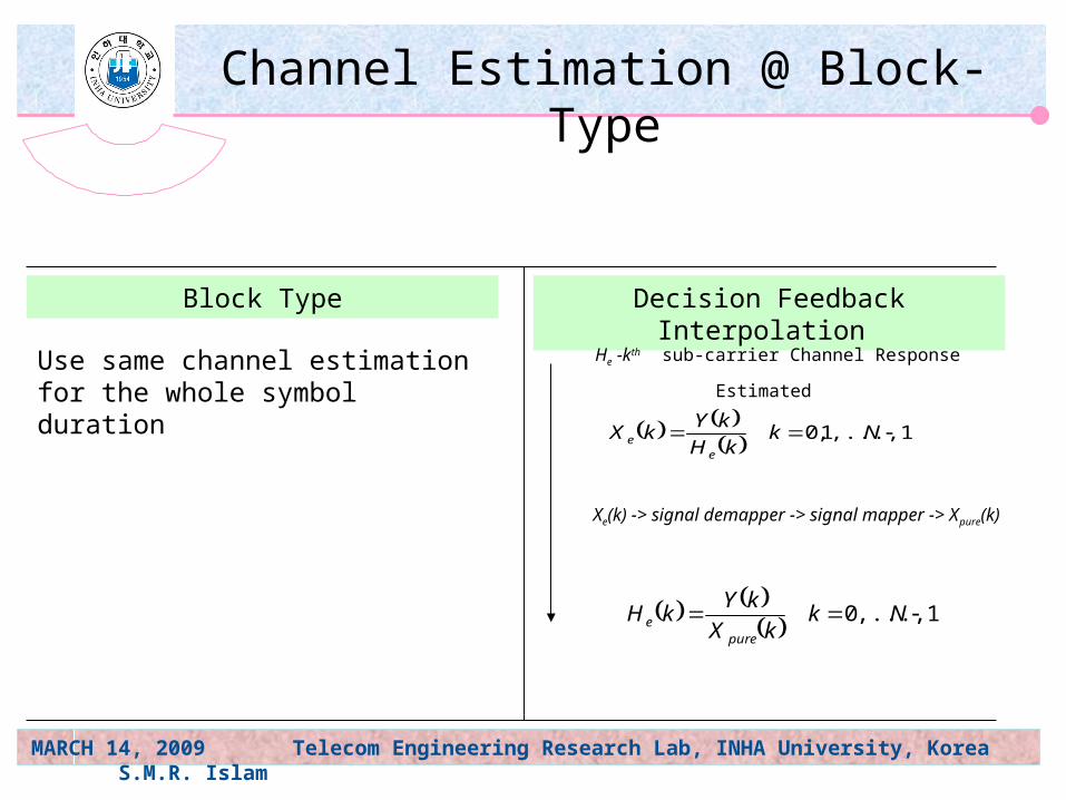
Channel Estimation @ Block-Type
Block Type Decision Feedback Interpolation
1,...,1,0 NkkH
kYkX
ee
1,...,0 NkkX
kYkH
puree
He -kth sub-carrier Channel Response Estimated
Xe(k) -> signal demapper -> signal mapper -> Xpure(k)
Use same channel estimation for the whole symbol duration
MARCH 14, 2009 Telecom Engineering Research Lab, INHA University, Korea S.M.R. Islam
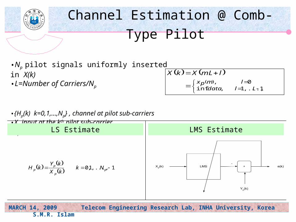
Channel Estimation @ Comb-Type Pilot
•Np pilot signals uniformly inserted in X(k)•L=Number of Carriers/Np
•{Hp(k) k=0,1,…,Np} , channel at pilot sub-carriers•Xp input at the kth pilot sub-carrier•Yp output at the kth pilot sub-carrier
LMS EstimateLS Estimate
0,
1,...,1,.inflmpx
Lldata
lmLXkX
1,...,1,0 p
p
pp Nk
kX
kYkH
MARCH 14, 2009 Telecom Engineering Research Lab, INHA University, Korea S.M.R. Islam
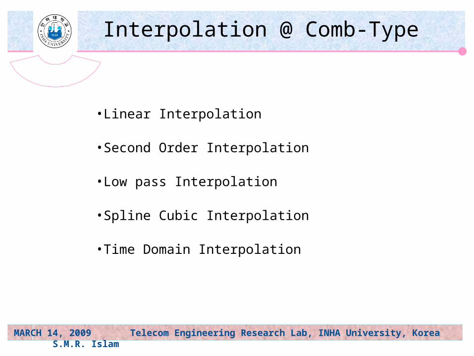
Interpolation @ Comb-Type
•Linear Interpolation
•Second Order Interpolation
•Low pass Interpolation
•Spline Cubic Interpolation
•Time Domain Interpolation
MARCH 14, 2009 Telecom Engineering Research Lab, INHA University, Korea S.M.R. Islam
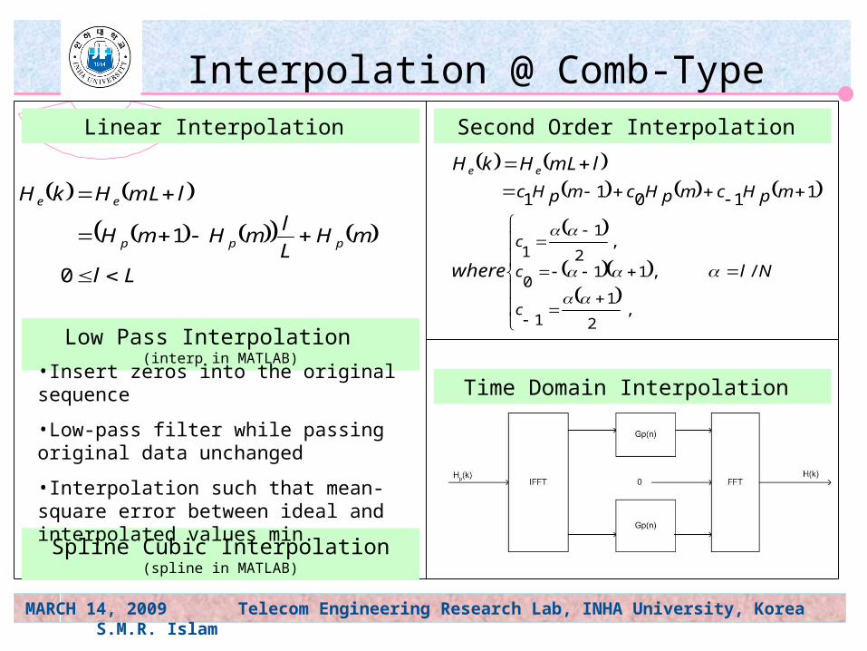
Ll
mHL
lmHmH
lmLHkH
ppp
ee
0
1
Linear Interpolation Second Order Interpolation
Nl
mpHcmpHcmpHc
c
c
c
where
lmLHkH ee
/
11011
,2
1
1
,110
,2
1
1
Low Pass Interpolation (interp in MATLAB)
Interpolation @ Comb-Type
Time Domain Interpolation
Spline Cubic Interpolation (spline in MATLAB)
•Insert zeros into the original sequence
•Low-pass filter while passing original data unchanged
•Interpolation such that mean-square error between ideal and interpolated values min.
MARCH 14, 2009 Telecom Engineering Research Lab, INHA University, Korea S.M.R. Islam
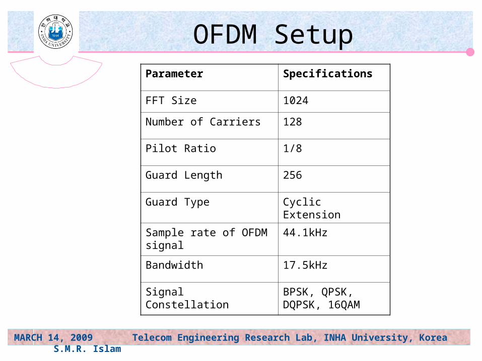
OFDM SetupParameter Specifications
FFT Size 1024
Number of Carriers 128
Pilot Ratio 1/8
Guard Length 256
Guard Type Cyclic Extension
Sample rate of OFDM signal
44.1kHz
Bandwidth 17.5kHz
Signal Constellation BPSK, QPSK, DQPSK, 16QAM
MARCH 14, 2009 Telecom Engineering Research Lab, INHA University, Korea S.M.R. Islam
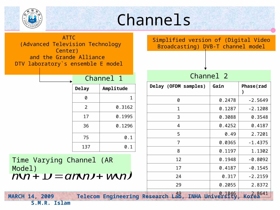
Channels
Delay (OFDM samples) Gain Phase(rad)
0 0.2478 -2.5649
1 0.1287 -2.1208
3 0.3088 0.3548
4 0.4252 0.4187
5 0.49 2.7201
7 0.0365 -1.4375
8 0.1197 1.1302
12 0.1948 -0.8092
17 0.4187 -0.1545
24 0.317 -2.2159
29 0.2055 2.8372
49 0.1846 2.8641
Delay Amplitude
0 1
2 0.3162
17 0.1995
36 0.1296
75 0.1
137 0.1
Channel 1 Channel 2
nwnahnh 1
Time Varying Channel (AR Model)
ATTC (Advanced Television Technology Center)
and the Grande Alliance DTV laboratory`s ensemble E model
Simplified version of (Digital Video Broadcasting) DVB-T channel model

MARCH 14, 2009 Telecom Engineering Research Lab, INHA University, Korea S.M.R. Islam
Simulation-1
Modulation BPSK
Channel Rayleigh Fading
H(n) Channel 1
Doppler Frequency
70Hz
MARCH 14, 2009 Telecom Engineering Research Lab, INHA University, Korea S.M.R. Islam
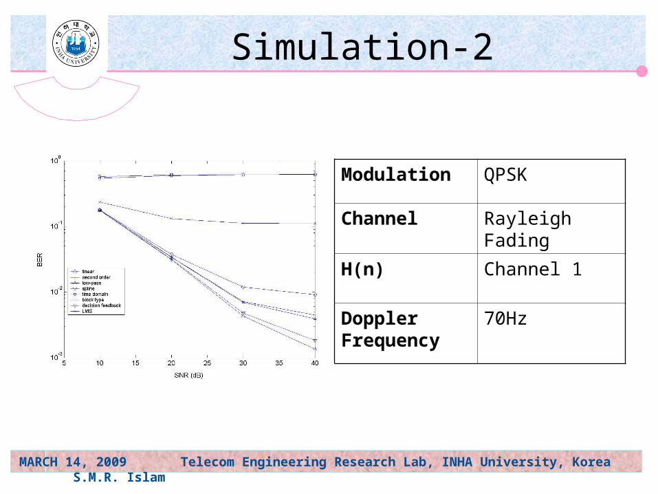
Modulation QPSK
Channel Rayleigh Fading
H(n) Channel 1
Doppler Frequency
70Hz
Simulation-2
MARCH 14, 2009 Telecom Engineering Research Lab, INHA University, Korea S.M.R. Islam
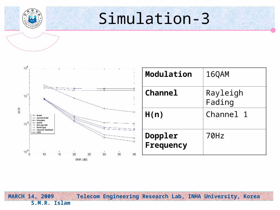
Modulation 16QAM
Channel Rayleigh Fading
H(n) Channel 1
Doppler Frequency
70Hz
Simulation-3
MARCH 14, 2009 Telecom Engineering Research Lab, INHA University, Korea S.M.R. Islam
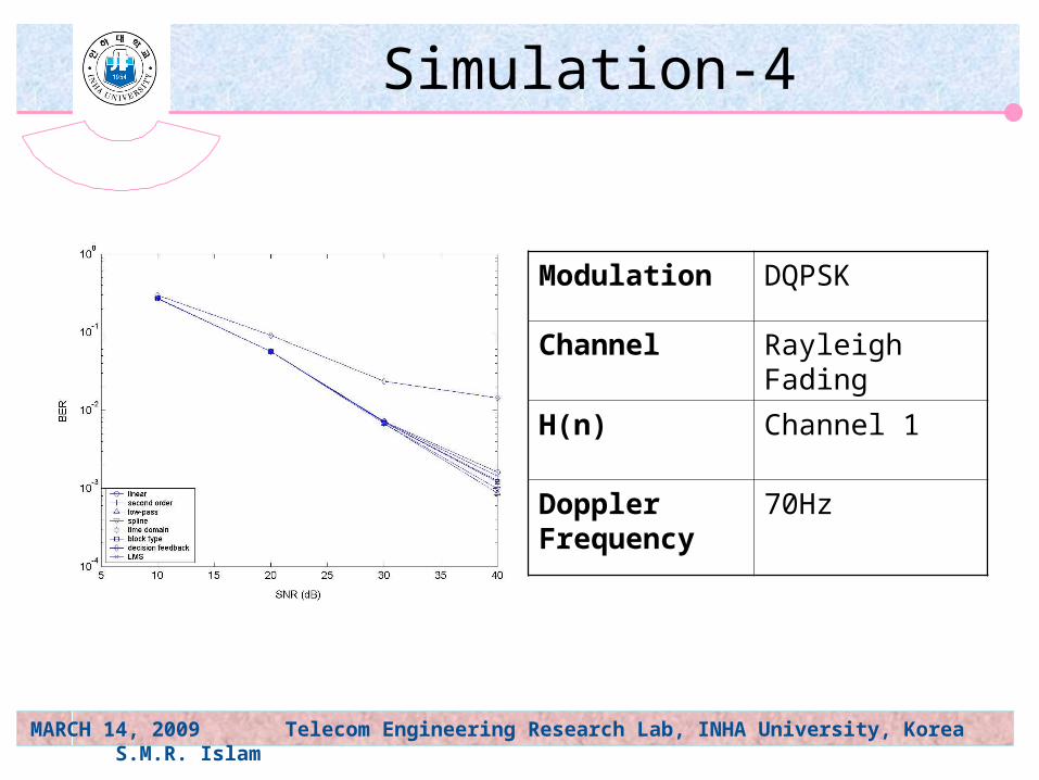
Modulation DQPSK
Channel Rayleigh Fading
H(n) Channel 1
Doppler Frequency
70Hz
Simulation-4
MARCH 14, 2009 Telecom Engineering Research Lab, INHA University, Korea S.M.R. Islam
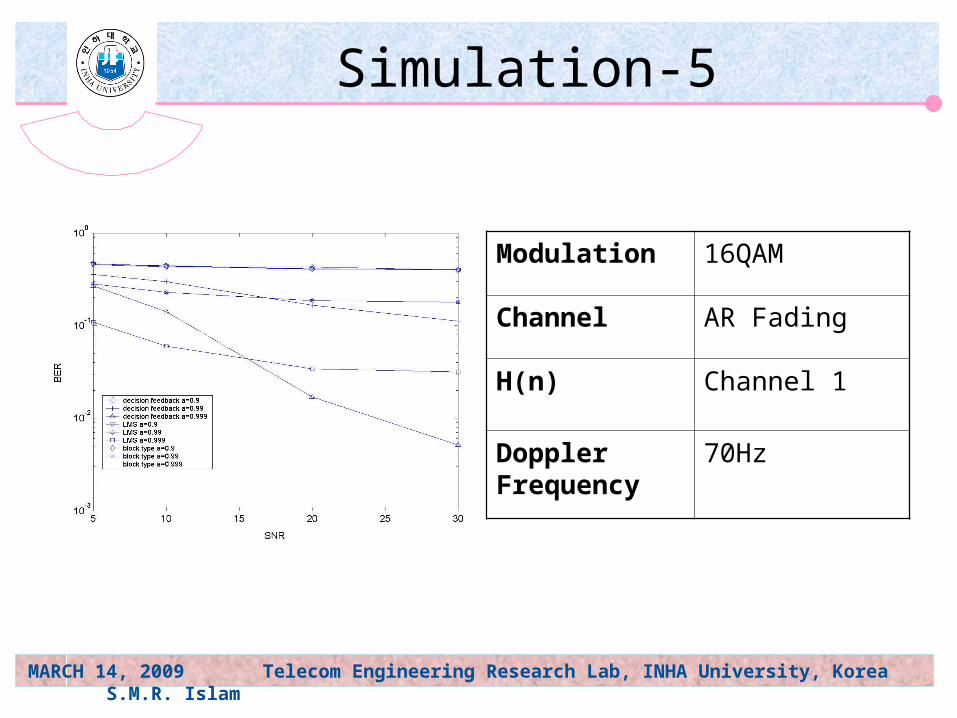
Simulation-5
Modulation 16QAM
Channel AR Fading
H(n) Channel 1
Doppler Frequency
70Hz
MARCH 14, 2009 Telecom Engineering Research Lab, INHA University, Korea S.M.R. Islam
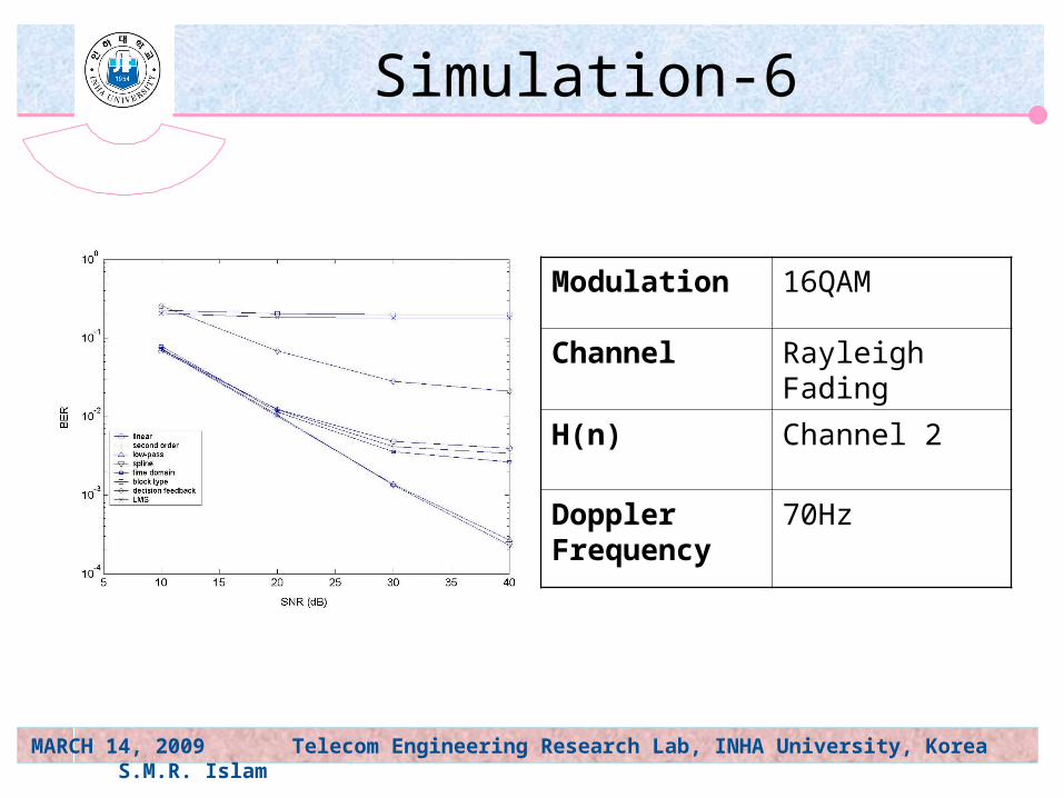
Modulation 16QAM
Channel Rayleigh Fading
H(n) Channel 2
Doppler Frequency
70Hz
Simulation-6
MARCH 14, 2009 Telecom Engineering Research Lab, INHA University, Korea S.M.R. Islam
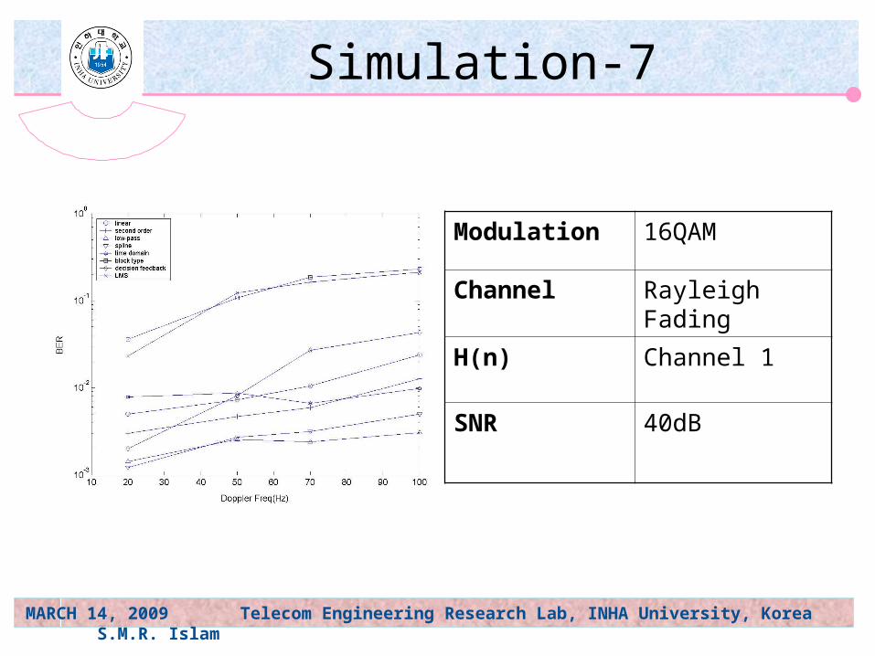
Modulation 16QAM
Channel Rayleigh Fading
H(n) Channel 1
SNR 40dB
Simulation-7
MARCH 14, 2009 Telecom Engineering Research Lab, INHA University, Korea S.M.R. Islam
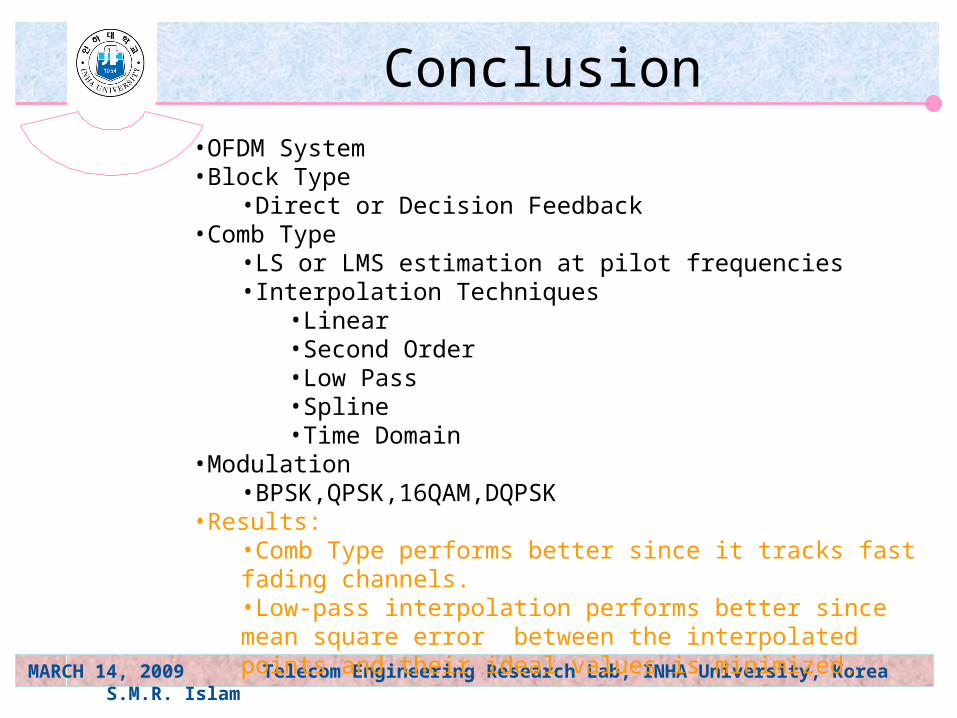
Conclusion•OFDM System•Block Type
•Direct or Decision Feedback•Comb Type
•LS or LMS estimation at pilot frequencies•Interpolation Techniques
•Linear•Second Order•Low Pass•Spline•Time Domain
•Modulation •BPSK,QPSK,16QAM,DQPSK
•Results:•Comb Type performs better since it tracks fast fading channels.•Low-pass interpolation performs better since mean square error between the interpolated points and their ideal values is minimized.