Embed Size (px)
Citation preview
MARCH PLASMA SYSTEMS GAS PLASMA SYSTEMS
Installation, Operation, and Maintenance Manual
PWB-SERIES C-SERIES RIE-SERIES PCB-SERIES
Computer Controlled Models with P²CIM


NOTICE This is a March Plasma publication which is protected by copyright. Original copyright date 2002. No part of this document may be photocopied, reproduced, or translated to another language without the prior written consent of March Plasma Systems. The information contained in this publication is subject to change without notice.
Contact Us March welcomes requests for information, comments, and inquiries about its products. Please contact us as follows:
March Plasma Systems 1000 112th Circle North Ste.1200
St. Petersburg, Florida 33716
Phone: (727) 573-4567 Fax: (727) 573-0333
Email: [email protected] Website: www.MarchPlasma.com
Trademarks The March corporate logo is a registered trademark of March Plasma Systems.
Rev. .3/2007

ii
WARRANTY The products manufactured by March Plasma Systems (MPS) are warranted against defects in material and workmanship for the periods specified at the bottom of this document. MPS’s liability under this warranty is limited, at the option of MPS, to repair or replacement of the product. Items expendable through normal use are not covered by this warranty. All warranty replacement or repair of parts shall be limited to equipment malfunction(s) which, in the sole opinion of MPS, are due or traceable to defects in the original materials or workmanship. All obligations of MPS under this warranty shall cease in the event of abuse, accident, alteration, misuse, or neglect of the equipment. In warranty repairs or replacement, all parts are warranted for only the remaining non expired portion of the original warranty period, applicable to the repaired or replaced parts. After expiration of the applicable warranty period, the customer will be charged at the then current prices for parts, labor, and transportation.
Reasonable care must be used to avoid hazards to the equipment. MPS expressly disclaims responsibility for loss or damage caused by the use of its products in ways other than in accordance with proper operating procedures.
EXCEPT AS STATED HEREIN, MPS MAKES NO WARRANTY, EXPRESSED OR IMPLIED, OF MERCHANTABILITY OR FITNESS FOR A PARTICULAR PURPOSE OR OTHERWISE. Statements made by any person, including representatives of MPS, which are inconsistent or in conflict with the terms of this warranty shall not be binding upon MPS unless specified in writing and approved by an officer of MPS.
All claims under warranty must be made promptly after the occurrence of circumstances giving rise thereto, and must be received within the applicable warranty period by MPS or its authorized representative. Such claims should include the product serial number, the date of shipment, and a full description of the circumstances giving rise to the claim. Before any products are returned for repair and/or adjustment, written authorization from MPS or its authorized representative for the return and instructions as to how and where these products should be returned, must be obtained. Any product returned to MPS for examination shall be sent freight prepaid via the means of transportation indicated as acceptable to MPS. MPS reserves the right to reject any warranty claim not promptly reported and any warranty claim on any item that has been altered or has been returned by non-acceptable means of transportation. When any product is returned for examination and/or inspection, or for any other reason, the customer shall be responsible for all damage resulting from improper packing or handling, and for loss in transit, notwithstanding any defect or nonconformity in the product. In all cases, MPS has the sole responsibility for determining the cause and nature of the failure; MPS’s determination with regard thereto shall be final.
If it has been found that the product has been returned without cause and is still serviceable, the customer will be notified and the product returned at its expense; in addition, a charge for testing and examination may be made to the products so returned.
WARRANTY PERIODS
Note: The system’s Date of manufacture (DOM) marks the beginning of the warranty period.
Electrodes, Chamber, Frame: 12 Months
Electronics: Pass Through
Vacuum Pump: 1 year (through manufacturer)
Wear items such as o-rings, oil, bushings, filters, and bearings are not covered under warranty.
iii
CUSTOMER SERVICE Field Service Engineer Rates
Service will be rendered to any customer for the repair, modification, or exchange of any equipment manufactured by March Plasma Systems or included as a purchased part of any equipment manufactured by March Plasma Systems.
In order for a request for service to be honored under warranty, a purchase order must accompany the request. The purchase order will cover travel and subsistence expenses only.
Under non-warranty work, the purchase order will cover travel expenses and travel time, including subsistence expenses, labor, and replacement parts.
Charges will be determined at the time of service and are subject to the conditions stated in the warranty.
Any work performed by field service personnel, either completed or continuing, will be reported to March Plasma Systems on the appropriate forms provided, dated, and signed by the customer and counter signed by the field service technician.

iv
Table of Contents 1 - Introduction ........................................................................................................... 1-1
1.1 General ...................................................................................................................................1-1 1.2 Conventions and Pictograms Used in this Manual.................................................................1-2 1.3 Pictograms Placed on the Equipment ....................................................................................1-2 1.4 Safety Considerations ............................................................................................................1-3
1.4.1 General ......................................................................................................................1-3 1.5 De-Commissioning and Disposal ...........................................................................................1-4
1.5.1 General ......................................................................................................................1-4 1.5.2 Oil/waste Disposal .....................................................................................................1-4 1.5.3 Other Considerations.................................................................................................1-4
2 - System Overview .................................................................................................. 2-1 2.1 General ...................................................................................................................................2-1 2.2 Major Equipment Parts ...........................................................................................................2-1
2.2.1 Vacuum Chamber......................................................................................................2-1 2.2.2 Manifold Unit..............................................................................................................2-2 2.2.3 Vacuum Pump ...........................................................................................................2-2 2.2.4 Blower Unit (Option) ..................................................................................................2-2 2.2.5 Power Distribution Box ..............................................................................................2-2 2.2.6 Mass Flow Controllers ...............................................................................................2-2 2.2.7 RF Power Supply.......................................................................................................2-3 2.2.8 Modular OPTO Interface System ..............................................................................2-3 2.2.9 P²CIM.........................................................................................................................2-3
2.3 System Operation Overview...................................................................................................2-3 2.4 Operator Controls (Power Panel Mounted) ............................................................................2-5
3 - Installation ............................................................................................................. 3-1 3.1 Site Selection..........................................................................................................................3-1
3.1.1 Floor Space ...............................................................................................................3-1 3.1.2 Other Considerations.................................................................................................3-1 3.1.3 Customer Installation Checklist .................................................................................3-3
3.2 Equipment Unloading and Positioning ...................................................................................3-4 3.3 Utility Connections..................................................................................................................3-4
3.3.1 Electrical Connections ...............................................................................................3-5 3.3.2 Gas and Air Connections...........................................................................................3-7 3.3.3 Exhaust Connections.................................................................................................3-8 3.3.4 Exhaust Lines ............................................................................................................3-8 3.3.5 Cooling Water Connections.....................................................................................3-10
4 - P²CIM2000 W2K Software................................................................................... 4-1 4.1 Introduction.............................................................................................................................4-1 4.2 System Requirements ............................................................................................................4-1
4.2.1 Running OptoMux Scan Program .............................................................................4-2 4.2.2 Adding Support Programs, Printer Drivers or Accessing Clocks Etc. .......................4-2
5 - P²CIM for Windows Operations Manual .............................................................. 5-1 5.1 Introduction.............................................................................................................................5-1 5.2 Computer Startup ...................................................................................................................5-1
5.2.1 System Access Levels...............................................................................................5-2 5.2.2 Main Menu.................................................................................................................5-2
5.3 Process Control ......................................................................................................................5-3 5.3.1 Automatic Process Mode...........................................................................................5-3 5.3.2 Manual Process Mode.............................................................................................5-10 5.3.3 Hibernate .................................................................................................................5-13 5.3.4 Wake-Up (Unhibernate)...........................................................................................5-13
v
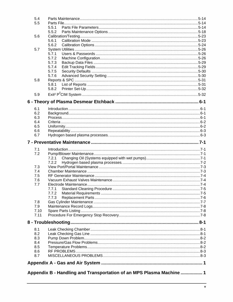
5.4 Parts Maintenance................................................................................................................5-14 5.5 Parts File...............................................................................................................................5-14
5.5.1 Parts File Parameters..............................................................................................5-14 5.5.2 Parts Maintenance Options .....................................................................................5-18
5.6 Calibration/Testing................................................................................................................5-23 5.6.1 Calibration Mode .....................................................................................................5-23 5.6.2 Calibration Options ..................................................................................................5-24
5.7 System Utilities .....................................................................................................................5-26 5.7.1 Users & Passwords .................................................................................................5-26 5.7.2 Machine Configuration.............................................................................................5-26 5.7.3 Backup Data Files ...................................................................................................5-29 5.7.4 Edit Tracking Fields .................................................................................................5-29 5.7.5 Security Defaults .....................................................................................................5-30 5.7.6 Advanced Security Setting ......................................................................................5-30
5.8 Reports & SPC .....................................................................................................................5-31 5.8.1 List of Reports .........................................................................................................5-31 5.8.2 Printer Set-Up..........................................................................................................5-32
5.9 Exit² P²CIM System ..............................................................................................................5-32 6 - Theory of Plasma Desmear Etchback ................................................................. 6-1
6.1 Introduction.............................................................................................................................6-1 6.2 Background.............................................................................................................................6-1 6.3 Process...................................................................................................................................6-1 6.4 Criteria ....................................................................................................................................6-2 6.5 Uniformity................................................................................................................................6-2 6.6 Repeatability ...........................................................................................................................6-3 6.7 Hydrogen based plasma processes. ......................................................................................6-3
7 - Preventative Maintenance .................................................................................... 7-1 7.1 Introduction.............................................................................................................................7-1 7.2 Pump/Blower Maintenance.....................................................................................................7-1
7.2.1 Changing Oil (Systems equipped with wet pumps)...................................................7-1 7.2.2 Hydrogen based plasma processes. .........................................................................7-2
7.3 View Port/Portal Maintenance ................................................................................................7-3 7.4 Chamber Maintenance ...........................................................................................................7-3 7.5 RF Generator Maintenance....................................................................................................7-4 7.6 Vacuum Exhaust Valves Maintenance...................................................................................7-4 7.7 Electrode Maintenance...........................................................................................................7-4
7.7.1 Standard Cleaning Procedure ...................................................................................7-5 7.7.2 Material Requirements ..............................................................................................7-5 7.7.3 Replacement Parts ....................................................................................................7-6
7.8 Gas Cylinder Maintenance .....................................................................................................7-7 7.9 Maintenance Record Logs......................................................................................................7-8 7.10 Spare Parts Listing .................................................................................................................7-8 7.11 Procedure For Emergency Stop Recovery.............................................................................7-8
8 - Troubleshooting.................................................................................................... 8-1 8.1 Leak Checking Chamber ........................................................................................................8-1 8.2 Leak Checking Gas Line ........................................................................................................8-1 8.3 Pump Down Problem..............................................................................................................8-2 8.4 Pressure/Gas Flow Problems.................................................................................................8-2 8.5 Temperature Problems...........................................................................................................8-2 8.6 RF PROBLEMS......................................................................................................................8-3 8.7 MISCELLANEOUS PROBLEMS............................................................................................8-3
Appendix A - Gas and Air System ............................................................................... 1
Appendix B - Handling and Transportation of an MPS Plasma Machine ................. 1

vi
Appendix C - Dry Pump Information............................................................................ 2

1-1
1 - Introduction
1.1 General
This manual covers the installation, operation, and maintenance for the PWB-Series, PCB-Series, and C-Series platforms and is applicable to older B-Series Plasma Systems manufactured by March Plasma Systems, St. Petersburg, Florida formerly known as Advanced Plasma Systems, Inc. herein referred to as MPS.
The MPS PWB, PCB and C Series Desmear/Etchback Systems are designed to remove resin smear from single, double, and multi-layer printed circuit boards, or any other product requiring surface treatment. MPS’s method is a dry process involving gases rather than liquids to treat products. The gases are excited to a plasma state by a RF generator, producing free radicals and ions. The resulting chemical reaction changes the resin smear into ash which is then removed by the continuous flow of gases during the remaining plasma treatment. Additional removal of contaminants from the waste gases can be accomplished by simple scrubber units. At no time during the plasma desmear/etchback process is the operator exposed to toxic hazards or harmful RF emissions. Plasma desmear/etchback also does not present the waste disposal problems inherent in chemical desmear/etchback systems.
This manual is intended for use by operator/service personnel having electro-mechanical experience or training. Service personnel must have knowledge of valves, pumps, and plumbing associated with systems using vacuum and high pressure gases, and have an understanding of wiring diagrams and schematics. They must also know how to use a multimeter and be able to remove and replace relays and similar electrical components using common tools. Knowledge of electronics, however, beyond the removal of major components, is not required.
This entire manual should be read by service/maintenance personnel. Operators should read sections I, II and IV completely. This manual must be kept near the plasma machine at all times.
Manuals are also provided which cover equipment used on the plasma desmear/etchback system, but are not manufactured by MPS. Refer to the manufacturer's manual for warranty information, parts or other specific information regarding a particular piece of equipment.
1

1-2
1.2 Conventions and Pictograms Used in this Manual Certain words or phrases may be in bold type to place emphasis on the word. Computer keyboard keys are shown in <Key> small brackets and is to be taken in that context.
Screen shots representing the computer screen are for reference only and may not show the exact information that is currently showing on your screen.
WARNING! These messages, marked with the triangular pictogram and printed in bold type, identify hazards which could result in severe bodily injury or death. Extreme caution therefore must be used by all operators and service personnel.
CAUTION! These messages, marked with the triangular icon and printed in bold type, identify possible dangers or procedures which could result in bodily harm to personnel or damage to the equipment. Caution is warranted regarding these situations.
1.3 Pictograms Placed on the Equipment Some or all of the following labels/signs may appear at different locations on the plasma machine or pumping equipment.
Label Description
Warning Label Color: varies. May appear anywhere on the machine to point out possible hazards. Hot Surfaces - Burns to fingers or hands Color: black on yellow background. Warning that surfaces may be hot enough to cause discomfort or burns.
Read Operator’s Manual Color: black on yellow background. Points out areas of the equipment that may require specific instructions.
Gloves must be worn Color: white on blue background. Gloves need to be worn during machine operation or handling of products.
High Voltage Color: black on yellow background. Warning of possible electric shock hazard areas.
1-3
1.4 Safety Considerations
1.4.1 General
MPS Plasma Machines are designed and intended for very specific usage and no attempt should be made to modify or use the machines for any other purpose. To do so could cause hazardous results. While the machines are designed with operator and service technician safety in mind, normal care must be observed as with any production machinery.
The maintenance section of this manual contains daily, weekly and periodic checks that must be made to insure proper safety and longevity to this equipment. Forms are provided to record these maintenance checks and should be used for that purpose.
CAUTION! Never operate these machines with skins or guards or safety devices removed or disabled. The cautions and warnings labeled on the machines and used in this manual are intended to prevent personal injury and/or equipment damage.
Vacuum chamber: These machines produce a very low pressure (vacuum) inside the chamber, manifolds, pumps and gas lines and should never be worked on or tampered with while a vacuum is present. No attempt should be made to release the vacuum outside of the normal operation of the machine.
CAUTION! No material or items except that which the machine was designed to process should ever be placed inside the vacuum chamber. The use of hydrocarbon oils inside the chamber or pumps can cause explosive reactions.
Fires or Emergencies: In the event of fire/smoke or electrical discharge the machine should be immediately stopped by depressing the “Emergency Stop” button. Power and gas supplies should be shut off at their source if possible without endangering personnel. Fires in or around the plasma machine may be chemical or electrical in nature and should be addresses as such.
When the emergency stop button is used while the machine is in operation all mechanical motion will stop but a vacuum will remain in the chamber and voltages will still be present in some electrical components. Electrical power boxes will still contain high voltages. Only qualified personnel should re-start the machine at this point and then in accordance with procedures outlined in Section 7 - Preventative Maintenance.
NOTE: Some arcing inside of the plasma chamber may be normal and harmless.
However severe arcing may destroy parts being treated or damage electrodes.
Arcing itself is not usually cause for an emergency stop. Operators must be trained to know when to abort a process run and to take appropriate action.
1-4
Exhaust: Gases produced by these machines may contain harmful components.
CAUTION! Exhaust gases MUST be vented at all times in accordance with the installation requirements in this manual.
Voltages: The electrical power boxes, RF generators and pumping systems contain possible harmful voltages and access panels should NEVER be opened except by qualified personnel. The feed (supply) lines to the main power panels remain energized even though the main disconnect may be in the OFF position.
WARNING! The RF generators produce very high voltages at possible lethal levels and personnel must avoid working on or tampering with these machines while RF generators are in operation.
Temperatures: During operation of this machine the inherent action of the plasma may cause parts inside the chamber to reach high temperatures.
CAUTION! Parts inside the vacuum chamber may be hot enough to cause burns right after the doors are opened. Use caution when removing parts or racks, the wearing of gloves is recommended.
1.5 De-Commissioning and Disposal
1.5.1 General
De-commissioning the plasma machine should be done in accordance with individual company policy and procedure. If the machine is to be stored or sold MPS service department should be contacted for help and advice before the machine is dismantled.
NOTE: See Appendix B - Appendix B - Handling and Transportation of an MPS Plasma Machine in this manual for more information on dismantling. Any further information regarding storage or dismantling is beyond the scope of this manual.
1.5.2 Oil/waste Disposal
The oil used in the vacuum pumps and blowers is a synthetic type (non-hydrocarbon) and is very expensive and cannot be disposed of like other oils. It should be cleaned and re-cycled or sold back to the manufacturer. See the Material Safety Data sheets in the back of this manual for more information or contact the oil distributor or manufacturer.
1.5.3 Other Considerations
Parts/pumps/exhaust hoses etc. that have been treated with plasma or discharge may contain acids or corrosive species and should be cleaned or safely disposed of. The inside of pumps or blowers may contain harmful materials and should be worked on only by qualified personnel with safety considerations in mind.

2-1
2 - System Overview
2.1 General The MPS Plasma System is comprised of eight (8) major units. These are:
Vacuum Chamber Power Distribution Box Manifold Unit RF Power Supply Vacuum Pump Modular Opto Interface System Blower Unit Computerized Controller
This section provides an overview of each of these major units. In the forthcoming discussions, the products being desmeared are printed circuit boards, although any manufactured items requiring plasma etching are suitable for this system. The following sections describe the individual units comprising the system. The information presented in this section pertains to all models unless specifically stated otherwise.
2.2 Major Equipment Parts 2.2.1 Vacuum Chamber
The vacuum chamber is the large, aluminum holding container in which the actual plasma process takes place. The chamber’s patented design is specially designed to enhance uniformity by keeping the flow of gases continuous and constant. The chamber is made up of four major parts that are described below.
1. Electrodes
The electrodes are the paired aluminum assemblies located inside the chamber. During the plasma cycle, these assemblies are excited by the RF generator (see 2.2.7 RF Power Supply), creating the actual plasma used to treat the products.
2. Purge Inlet Port
The purge inlet port is a high-pressure feed located on the side of the chamber. At the end of the process, it removes residual reactant gases from the chamber before breaking vacuum.
3. Vacuum Break
The vacuum break allows the chamber to return to atmospheric pressure after the completion of a plasma cycle. The chamber can then be opened and the products removed.
4. Chamber Door Assembly
The door assembly allows the chamber to be accessed.
2
2-2
2.2.2 Manifold Unit
The manifold contains all the inlet and exhaust equipment to vent gases to and from the chamber. This allows a periodic reversal of flow of gases through the chamber during the process cycle, insuring uniformity in the finished product. In some applications, the process gas is conducted to the center of the chamber by special manifolds. In this case, the right and left inlets and exhausts are all open simultaneously during process.
1. Right and Left Gas Inlets
The right and left gas inlets are on/off valves that allow the mixed gases to flow into the chamber. They are located on the vacuum piping on both sides of the chamber.
2. Right and Left Exhaust Valves
The right and left exhaust valves are located on the manifolds on both sides of the chamber. The valves are opened to allow the gases to be evacuated from the chamber.
2.2.3 Vacuum Pump
The vacuum pump unit is a two-stage mechanical pump that removes gases from the chamber, insuring a continuous flow. Table 3-1 provides the pump specifications.
The vacuum pump requires nitrogen ballasting while it is running in order to purify the oil and minimize the buildup of corrosive acids and moisture.
The waste gases and reaction products created during the plasma process are exhausted from the pump through a PVC 40 scheduled connection.
2.2.4 Blower Unit (Option)
The blower assists the vacuum pump to produce faster pump down time.
2.2.5 Power Distribution Box
The power distribution box is mounted on the frame below the vacuum chamber. It contains the motor starters and overload heaters for the pump and blower. It also contains the primary power disconnect, the OPTO digital I/O board and relays used in the process and interlock circuits.
The handle on the door of the box operates the primary power disconnect and is also used to open the door. Mounted on the door are the PUMP ON-OFF and BLOWER ON-OFF push-buttons. See 2.4 Operator Controls (Power Panel Mounted) for explanation of operator controls.
2.2.6 Mass Flow Controllers
The mass flow controllers regulate the flow of gas into the chamber.

2-3
2.2.7 RF Power Supply
This unit supplies the RF energy to the electrodes. Depending on the model, the RF power supply provides power ranging from 300 to 20,000 watts. The standard power units are listed in Table 3-1.
2.2.8 Modular OPTO Interface System
This system of interface electronics monitors machine operation and passes computer commands/control to and from the mechanical systems.
2.2.9 P²CIM
The P²CIM system consists of the following equipment:
1. A state-of-the-art computer system complete with a CD ROM drive, hard disk drive, printer and all the necessary software to operate the peripheral equipment of the system.
2. Uninteruptable power supply and interface board assemblies.
3. A line conditioner for 115 VAC to protect the computer equipment from power transients.
2.3 System Operation Overview
This section describes the system during an operational cycle, starting from the initial conditions prior to a cycle to final shutdown.
1. The Vacuum Pump is running.
2. The Nitrogen Ballast Valve is open.
3. The Right and Left Exhaust Valves are open.
4. Air in the chamber is evacuated through exhaust ports by the vacuum pump until the pressure is at or below the minimum pressure.
5. At minimum pressure, the Right Exhaust closes, the Left Exhaust remains open, but with central inlet manifolding both exhausts remain open (both inlets open in the next step).
6. The Right Gas Inlet opens and gases begin to flow.
7. When the pressure reaches the desired level, the RF Power Supply activates, and energy is applied to the Electrodes in the chamber. The gases are ionized, and the resulting plasma floods the surface and holes of the products.
8. Active species are produced in the plasma and diffused throughout the chamber. The new compounds formed by the reactants are continually evacuated through the manifold by the Vacuum Pump. Particulates can be removed from the pump oil by an optional filter system.
9. After an amount of time specified in the parameters (gas cycle time), the chamber’s Left Exhaust and Right Inlet Valves close and the Right Exhaust and Left Inlet Valves open. The gases are now drawn through the chamber in the opposite direction by the pull of the vacuum pump. With
2-4
central inlet manifolding, all inlets and exhausts remain open during processing.
10. This cycle is reversed at each interval, as selected above. The flow alternates so that the gases flow back and forth, over and through the suspended products, providing uniformity as the final results.
11. The RF Power Supply deactivates.
12. When the process is completed, the Gas Inlet Valves close and the Exhaust Valves open (or stay open).
13. The Purge Valve opens for a period of one second, venting purge gas into the chamber. As the chamber continues to be evacuated, this cycle is repeated a number of times, thus flushing the chamber.
14. After the purge is completed, the chamber is pumped down to minimum pressure.
15. All valves close and the Vacuum Break Valve opens, letting air into the chamber.
16. The chamber door is opened and the products are removed from the chamber. New products are then loaded for continued processing.
2-5
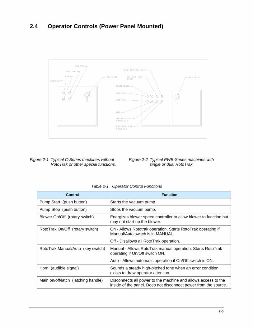
2.4 Operator Controls (Power Panel Mounted)
Figure 2-1 Typical C-Series machines without RotoTrak or other special functions.
Figure 2-2 Typical PWB-Series machines with single or dual RotoTrak.
Table 2-1 Operator Control Functions
Control Function
Pump Start (push button) Starts the vacuum pump.
Pump Stop (push button) Stops the vacuum pump.
Blower On/Off (rotary switch) Energizes blower speed controller to allow blower to function but may not start up the blower.
RotoTrak On/Off (rotary switch) On - Allows Rototrak operation. Starts RotoTrak operating if Manual/Auto switch is in MANUAL.
Off - Disallows all RotoTrak operation.
RotoTrak Manual/Auto (key switch) Manual - Allows RotoTrak manual operation. Starts RotoTrak operating if On/Off switch ON.
Auto - Allows automatic operation if On/Off switch is ON.
Horn (audible signal) Sounds a steady high-pitched tone when an error condition exists to draw operator attention.
Main on/off/latch (latching handle) Disconnects all power to the machine and allows access to the inside of the panel. Does not disconnect power from the source.


3-1
3 - Installation
3.1 Site Selection
The selection of an appropriate installation site for the PCB, PWB or C-Series system should be made from both the general recommendations given below and the customer’s individual needs. Careful installation and site selection eases installation problems, reduces costs, and improves operational efficiency.
3.1.1 Floor Space
NOTE: Refer to Figure 3-1. See Appendix B - Appendix B - Handling and Transportation of an MPS Plasma Machine for information on handling and transportation.
1. The site floor should be level, with no irregularities, and should be capable of supporting the appropriate weight of the system. See Table 3-1 for a listing of the MPS Plasma machine weights and measurements.
2. The system should be placed as near as possible to the required utilities specified in this section.
3. Sufficient workspace should be provided around the system as well as space for the storing, loading, and unloading of compressed gas cylinders.
4. Sufficient floor area around the system is also needed to accommodate a fork lift during equipment installation.
3.1.2 Other Considerations
1. During operation, MPS Plasma’s machines can give off up to 28,000 BTUs per hour. This can create uncomfortable working conditions and if extreme enough may cause the system to malfunction. Humidity levels may have little or no effect on the machine but may affect pump down times, therefore sites should be equipped with the proper air conditioning equipment.
2. The electrical components, such as the RF generator and front panel controllers, should neither be exposed to temperatures exceeding 900 degrees F (320 C), nor caustic fumes of any type; both can affect the electrical and electronic circuitry.
3. Process gases/compressed gas cylinders need to be placed as close as possible to the rear of the plasma machine and connected with approved fittings/tubing. Gas lines should to be placed above machine level or below floor level so access ways are not blocked and to protect them from damage by carts, trucks, service personnel etc.
3
3-2
4. A separate and dedicated grounding connection is required to eliminate RF noise. Install this ground wire with the 3-phase power feed as per National Electric Code and per local codes and regulations
5. A compressed air supply 60-100 psi (4.2-7bar/kg/cm2) is required. Air must be dried and filtered to remove all particles over 5 microns. A pressure regulator should be used if necessary to maintain the required pressure.
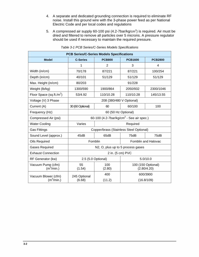
Table 3-1 PCB Series/C-Series Models Specifications
PCB Series/C-Series Models Specifications Model C-Series PCB800 PCB1600 PCB2800
1 2 3 4
Width (in/cm) 70/178 87/221 87/221 100/254
Depth (in/cm) 40/101 51/129 51/129 51/129
Max. Height (in/cm) 80/203 91/228
Weight (lb/kg) 1300/590 1900/864 2050/932 2300/1046
Floor Space (sq.ft./m2) 53/4.92 110/10.28 110/10.28 145/13.55
Voltage (V) 3 Phase 208 (380/480 V Optional)
Current (A) 30 (60 Optional) 60 60/100 100
Frequency (Hz) 60 (50 Hz Optional)
Compressed Air (psi) 60-100 (4.2-7bar/kg/cm2 - See air spec.)
Water Cooling Varies Required
Gas Fittings Copper/brass (Stainless Steel Optional)
Sound Level (approx.) 45dB 65dB 75dB 75dB
Oils Required Fomblin Fomblin and Halovac
Gases Required N2, O, plus up to 5 process gases
Exhaust Connection 2 in. (5 cm) PVC
RF Generator (kw) 2.5 (5.0 Optional) 5.0/10.0
Vacuum Pump (cfm) (m3/min.)
55 (1.54)
100 (2.80)
100 (150 Optional) (2.80/4.20)
Vacuum Blower (cfm) (m3/min.)
245 Optional (6.68)
400
(11.2)
600/3900
(16.8/109)

3-3
3.1.3 Customer Installation Checklist
The Customer Installation Checklist is forwarded to every customer prior to machine delivery along with a floor plan drawing showing the suggested location of all components.
This document explains exactly what utilities and services are required at the proposed location of the plasma machine and the locations of all related equipment.
The purpose of the Customer Installation Checklist is so all hook-ups and installation requirements may be completed by the time the machine arrives.
It is important that these pre-installation requirements are correctly done by the time the machine arrives so our field service Engineers can complete the installation in a timely manner. To this end we ask that the Customer Installation Checklist be signed and returned to MPS Customer Service when the work has been completed.
Questions regarding hook-ups and/or the placing of equipment may be directed to Customer Service (727-573-4567 ext. 268) or the Engineering dept. at MPS.
3-4
2” /5cm Exhaust Connection
Gas/Air Connections
Pump
Pump Water In
Pump Water Out
Water In/Out
Main Electrical
Enclosure
Electrical Power Supply
ConnectionsTOP VIEWMACHINE FRONT
2” /5cm Exhaust Connection
Gas/Air Connections
Pump
Pump Water In
Pump Water Out
Water In/Out
Main Electrical
Enclosure
Electrical Power Supply
ConnectionsTOP VIEWMACHINE FRONT
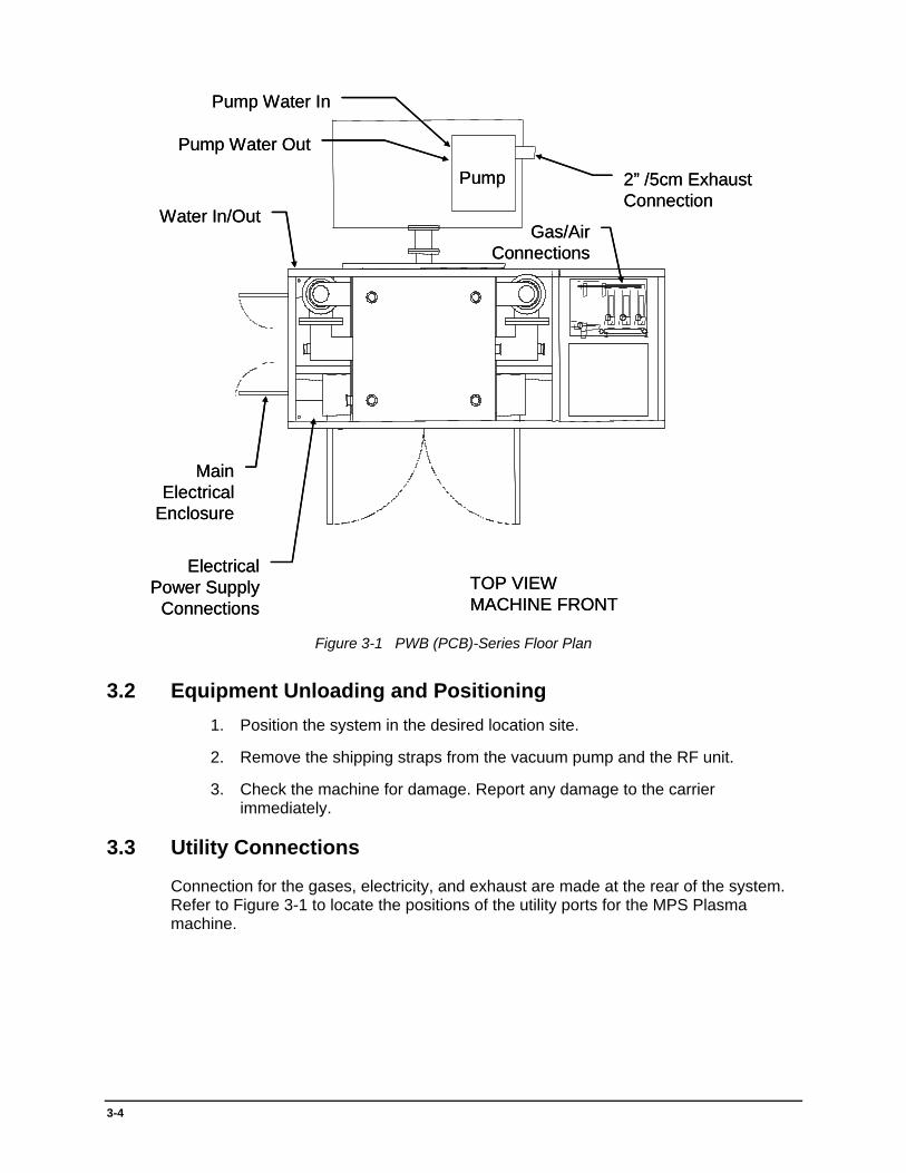
Figure 3-1 PWB (PCB)-Series Floor Plan
3.2 Equipment Unloading and Positioning 1. Position the system in the desired location site.
2. Remove the shipping straps from the vacuum pump and the RF unit.
3. Check the machine for damage. Report any damage to the carrier immediately.
3.3 Utility Connections
Connection for the gases, electricity, and exhaust are made at the rear of the system. Refer to Figure 3-1 to locate the positions of the utility ports for the MPS Plasma machine.

3-5
3.3.1 Electrical Connections
WARNING! Before making any electrical connections, make sure that the primary power is OFF. Lethal voltages are present when the primary power is active. Serious injury or death may result from contact with these voltages. Comply with all local and national electrical codes when installing wiring.
1. Materials Needed:
a. Recommended wire type for power leads:
#10 gauge AWG(UL)FR-1 for 30 amp service
# 6 gauge AWG(UL)FR-1 for 60 amp service
# 2 gauge AWG(UL)FR-1 for 100 amp service
Note: The wiring should be run from the primary power source to the system through a separate, approved conduit for protection.
b. Power Requirements from external source:
208/380 volts (see machine specific transformer requirements).
3 phase
30 amps (60 or 100 amps with some options)
2. Connections at the Power Distribution Box:
Note: Refer to Figure 3-2.
a. The electrical connections are made through the top of the Power Distribution Box.
b. Slip the wires running from the primary power source through the hole (not provided).
c. Open the door on the Power Distribution Box. Locate the three (3) set screw terminals attached to the Power Disconnect at the upper right of the box.
d. Connect the ground wire to the set screw terminal near the upper left corner of the disconnect in the Power Distribution Box.
e. Connect each of the three-phase leads running into the system from the power source to the set screw terminal connectors on the power disconnect.
f. Some applications may require a neutral wire also.
Note: All wire connections are made by slipping the wire into the top of the set screw. Secure the wire to the terminal by tightening the screw on the front.
3-6
3-Phase 4-Wire Power Source
Top of Power Distribution Box
Set Screw Terminals
Power Disconnect
Ground Wire
Circuit Breaker
3-Phase 4-Wire Power Source
Top of Power Distribution Box
Set Screw Terminals
Power Disconnect
Ground Wire
Circuit Breaker
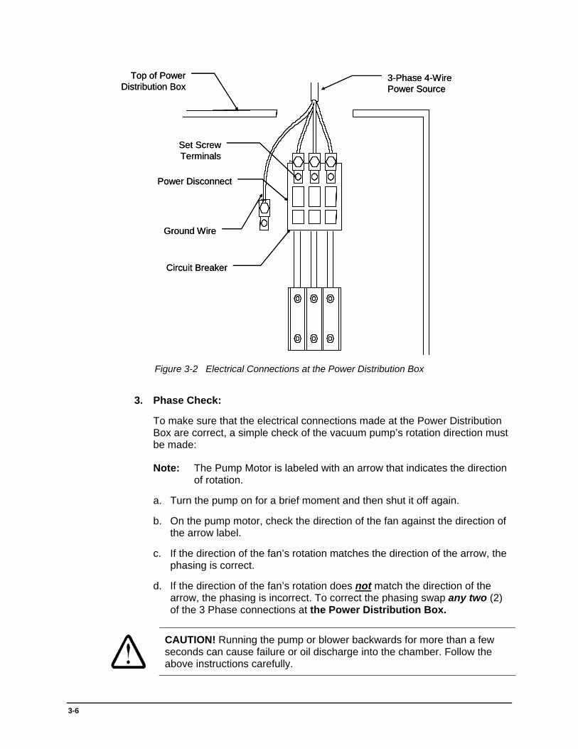
Figure 3-2 Electrical Connections at the Power Distribution Box
3. Phase Check:
To make sure that the electrical connections made at the Power Distribution Box are correct, a simple check of the vacuum pump’s rotation direction must be made:
Note: The Pump Motor is labeled with an arrow that indicates the direction of rotation.
a. Turn the pump on for a brief moment and then shut it off again.
b. On the pump motor, check the direction of the fan against the direction of the arrow label.
c. If the direction of the fan’s rotation matches the direction of the arrow, the phasing is correct.
d. If the direction of the fan’s rotation does not match the direction of the arrow, the phasing is incorrect. To correct the phasing swap any two (2) of the 3 Phase connections at the Power Distribution Box.
CAUTION! Running the pump or blower backwards for more than a few seconds can cause failure or oil discharge into the chamber. Follow the above instructions carefully.

3-7
3.3.2 Gas and Air Connections
CAUTION! Compressed gas cylinders must be safely secured to the wall and should be protected from accidental impact from loading carts, fork lifts, etc.
MPS strongly urges the customer to post all proper safety signs at the installation site according to local and regional standards.
Note: Refer to Table 3-2 for specifications on some of the compressed gases used in the MPS Plasma machines.
1. Connections are made to the machine with ¼” dia. (US) compression fittings. Adapters are available to connect ¼” dia. (US) to 6mm or 8mm tubing.
2. Use the following steps to properly install the compression fittings.
a. Insert the tubing into the compression fitting. Make sure that the tubing rests firmly on the shoulder of the fitting and that the nut is finger-tight.
b. Before tightening the nut, scribe the nut at the six o’clock position.
c. Hold the fitting body steady with a back-up wrench. Tighten the nut one-and-one-quarter turns (The scribe mark will make one revolution and continue to the nine o’clock position).
Note: To prevent leaks in the gas line, MPS recommends the use of Swagelok brand compression fittings exclusively.
3. All gas and air connections are made at the bulkhead panel on the rear of the system.
> Refer to Figure 3-1 for location of the gas connection port.
a. Connect the industrial nitrogen supply to the purge and ballast coupling.
b. Connect the process gases to the appropriate coupling.
c. Connect the compressed air supply to the compressed air coupling.
Note: MPS recommends that all of the information on gases should be thoroughly read and understood.
CAUTION! Gas and air pressures must be regulated to conform to the guidelines in 3.1.2 Other Considerations and Table 3-1 in this manual. Be sure sources are turned OFF before connecting or disconnecting gas/air lines.

3-8
3.3.3 Exhaust Connections
1. A 2-inch/5cm schedule 40 PVC outlet should be installed to vent the reaction products from the vacuum pump. The PVC should extend 10 feet/3.5 m above the roof, and should be placed away from both air intake vents (such as air conditioning vents) and exhaust vents for any other systems. Rain protection (or point opening down) is also required. A condensation trap with drain should be installed at the lowest point in the exhaust line.
Note: PVC is the preferred material for the exhaust line. Other materials, such as galvanized steel, have a tendency to corrode when used to vent plasma systems. This can be extremely hazardous if exhaust lines are to be installed over electrical components or wiring.
WARNING! The plasma system’s exhaust line should NEVER be used in conjunction with exhaust lines from other systems. The exhaust should be a dedicated line unique to this machine. The high oxygen content of the exhaust could present a fire hazard if mixed with other vented gases or materials (especially exhaust with a high oil content).
2. A buildup of hydrofluoric acid and other waste materials can occur if exhaust lines must run horizontally over long distances. Do not allow a low spot (trap) to occur between the pump and the point where the piping exits the building. Condensation drains should be installed into the piping at the lowest point to alleviate this buildup.
3. The pressure in the exhaust line used to vent waste materials from the system must not exceed the maximum back pressure the vacuum pump can handle. Therefore, special consideration should be made in the design of the exhaust line to ensure that the pump will operate properly under the pressure of the gases. These considerations should include such matters as the length of the exhaust line, the positioning of the machinery within the facility, and the diameter of the piping to be used.
Note: The maximum back pressure for Stokes pumps used on MPS Plasma Systems is 3 psi.(.21bar/kg/cm2).
3.3.4 Exhaust Lines
1. Connect the exhaust line to the exhaust outlet on the oil mist separator. Refer to Figure 3-1 for the position of the exhaust port.
2. Drop the exhaust pipe down into the system at the rear. Attach the end of the exhaust pipe to the oil mist separator with a hose clamp. Replace the back panel if necessary.
CAUTION! Be sure to allow the epoxy used to assemble the exhaust line at least twenty-four hours to dry before running exhaust through the line. Most epoxies give off heat while drying and could present a fire hazard if combined with the high oxygen content and the contaminants of the exhaust.

3-9
Table 3-2 Some Recommended Compressed Gases with Regulators
OXYGEN (Process Gas) Industrial Grade Cylinder
Size Cylinder Dimension
in./cm Contents
(cu.ft./dm3) (lbs./kg.) Gross Weight
(lbs./kg.) A 9 x 55 (23 x 140) (336/9,519) (27.9/12.6) (170/77.11) Regulator: Contact your local gas supplier Inlet Connection: CGA-540 Delivery range: 0 - 30 psig (0 - 2.11 bar/kg/cm
2)
Outlet shutoff valve: ¼” Swagelok connection Consumption: 1 Cylinder per week for two shifts operating per day
Impurities Analysis: AR: 10-20 ppm CF
4: .0 ppm THC: .0 ppm
CO: .0 ppm CO2: .5 ppm WATER: .0 ppm
N2: 10-40 ppm N
2O: .1 ppm DEW POINT: -1050F /-770C
FREON-14
CF4 TETRAFLUOROMETHANE (Process Gas) Ultrapure Carrier Grade
Cylinder Size
Cylinder Dimension in./cm
Contents (cu.ft./dm3) (lbs./kg.)
Gross Weight (lbs./kg.)
B 10 x 56 (26 x 143) (308/8,726) (70/31.75) (193/87.54) Regulator: Contact your local gas supplier Inlet Connection: CGA-540 Delivery range: 0 - 30 psig (0 - 2.11 bar/kg/cm
2)
Outlet shutoff valve: ¼” Swagelok connection Consumption: 1 Cylinder per two months for two shifts operating per day
NITROGEN (Process Gas) Industrial Grade
Cylinder Size
Cylinder Dimension in./cm
Contents (cu.ft./dm3) (lbs./kg.)
Gross Weight (lbs./kg.)
A 9 x 55 (23 x 140) (301/8,527) (22/9.98) (163/73.94) Regulator: Contact your local gas supplier Inlet Connection: CGA-580 Delivery range: 0 - 30 psig (0 - 2.11 bar/kg/cm
2)
Outlet shutoff valve: ¼” Swagelok connection Consumption: 1 Cylinder per two months for two shifts operating per day
Impurities Analysis: AR: 0 ppm O
2: 1.0 ppm THC: .5 ppm
CO: .0 ppm CO2: 5 ppm WATER: .0 ppm
H2: .0 ppm N2O .1 ppm DEW POINT: -1050F / -770C
NITROGEN (Purging and Ballasting Gas) Industrial Grade
Cylinder Size
Cylinder Dimension in./cm
Contents (cu.ft./dm3) (lbs./kg.)
Gross Weight (lbs./kg.)
A 9 x 55 (23 x 140) (301/8,527) (162/73.48) (162/73.48) Regulator: Contact your local gas supplier Inlet Connection: CGA-580 Delivery range: 0 - 30 psig (0 - 2.11 bar/kg/cm
2)
Outlet shutoff valve: ¼” Swagelok connection Consumption: 2-3 Cylinders per week for two (2) shifts operating per day
(Higher with some pump packages or adverse conditions)
3-10
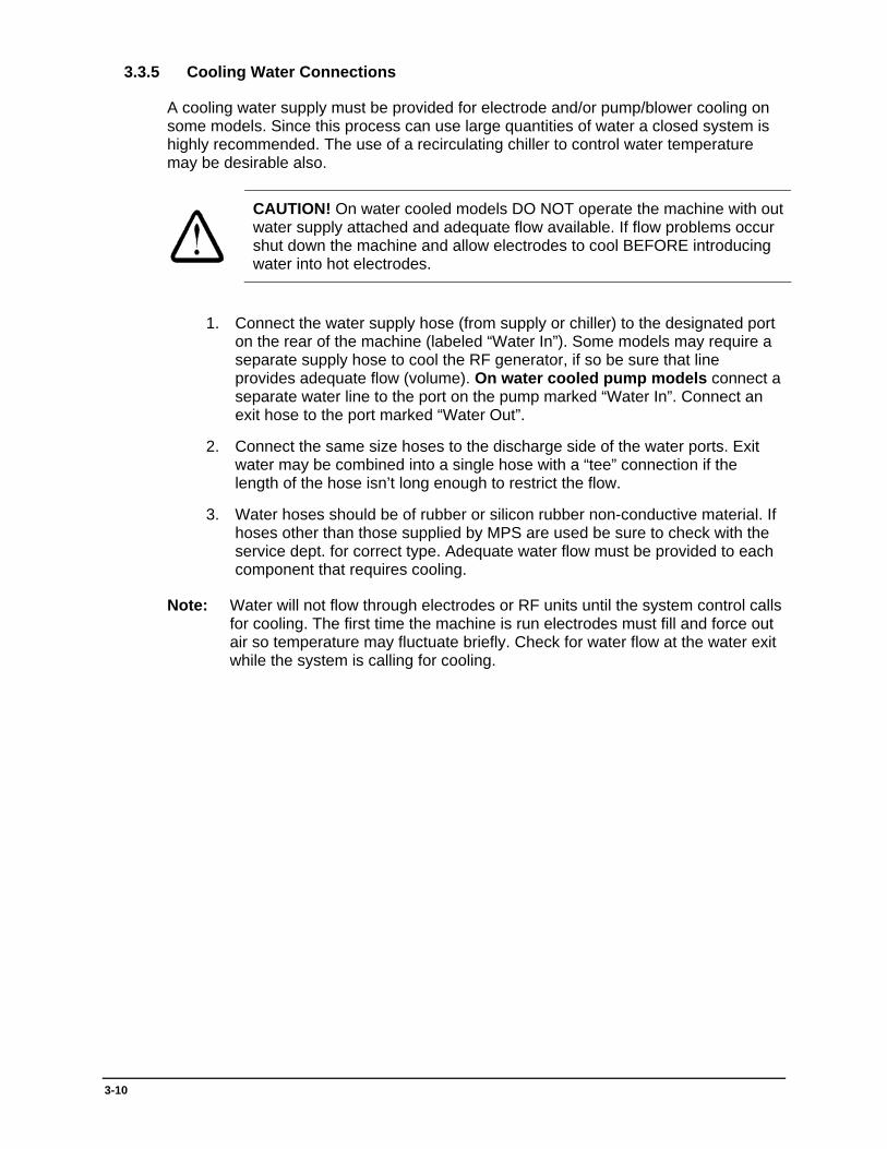
3.3.5 Cooling Water Connections
A cooling water supply must be provided for electrode and/or pump/blower cooling on some models. Since this process can use large quantities of water a closed system is highly recommended. The use of a recirculating chiller to control water temperature may be desirable also.
CAUTION! On water cooled models DO NOT operate the machine with out water supply attached and adequate flow available. If flow problems occur shut down the machine and allow electrodes to cool BEFORE introducing water into hot electrodes.
1. Connect the water supply hose (from supply or chiller) to the designated port on the rear of the machine (labeled “Water In”). Some models may require a separate supply hose to cool the RF generator, if so be sure that line provides adequate flow (volume). On water cooled pump models connect a separate water line to the port on the pump marked “Water In”. Connect an exit hose to the port marked “Water Out”.
2. Connect the same size hoses to the discharge side of the water ports. Exit water may be combined into a single hose with a “tee” connection if the length of the hose isn’t long enough to restrict the flow.
3. Water hoses should be of rubber or silicon rubber non-conductive material. If hoses other than those supplied by MPS are used be sure to check with the service dept. for correct type. Adequate water flow must be provided to each component that requires cooling.
Note: Water will not flow through electrodes or RF units until the system control calls for cooling. The first time the machine is run electrodes must fill and force out air so temperature may fluctuate briefly. Check for water flow at the water exit while the system is calling for cooling.

4-1
4 - P²CIM2000 W2K Software
4.1 Introduction
This document will step you through the process of installing the P²CIM 2000 Operating System onto a March Plasma Systems Inc.’s machine. This software is licensed for use by customers of March Plasma Systems, Inc. only. Any unauthorized use is prohibited.
Note: If the software is already installed and running please skip to page 27 for operating instructions.
4.2 System Requirements Pentium IBM compatible computer 200MHz or higher
Windows 2000 PROFESSIONAL with latest Service Pack installed
128Mb RAM (minimum)
40 Gig hard disk drive (minimum)
CD ROM drive
3.5” floppy disk drive
1 available RS-232 Serial Port (2 if Bar Code Reader Installed)
External OptoMux Network Adapter (APS, Inc. supplied)
4
4-2
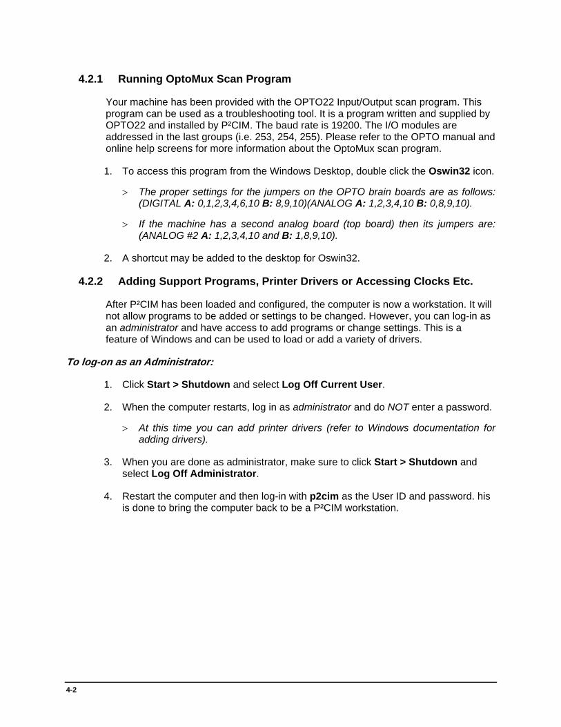
4.2.1 Running OptoMux Scan Program
Your machine has been provided with the OPTO22 Input/Output scan program. This program can be used as a troubleshooting tool. It is a program written and supplied by OPTO22 and installed by P²CIM. The baud rate is 19200. The I/O modules are addressed in the last groups (i.e. 253, 254, 255). Please refer to the OPTO manual and online help screens for more information about the OptoMux scan program.
1. To access this program from the Windows Desktop, double click the Oswin32 icon.
> The proper settings for the jumpers on the OPTO brain boards are as follows: (DIGITAL A: 0,1,2,3,4,6,10 B: 8,9,10)(ANALOG A: 1,2,3,4,10 B: 0,8,9,10).
> If the machine has a second analog board (top board) then its jumpers are: (ANALOG #2 A: 1,2,3,4,10 and B: 1,8,9,10).
2. A shortcut may be added to the desktop for Oswin32.
4.2.2 Adding Support Programs, Printer Drivers or Accessing Clocks Etc.
After P²CIM has been loaded and configured, the computer is now a workstation. It will not allow programs to be added or settings to be changed. However, you can log-in as an administrator and have access to add programs or change settings. This is a feature of Windows and can be used to load or add a variety of drivers.
To log-on as an Administrator:
1. Click Start > Shutdown and select Log Off Current User.
2. When the computer restarts, log in as administrator and do NOT enter a password.
> At this time you can add printer drivers (refer to Windows documentation for adding drivers).
3. When you are done as administrator, make sure to click Start > Shutdown and select Log Off Administrator.
4. Restart the computer and then log-in with p2cim as the User ID and password. his is done to bring the computer back to be a P²CIM workstation.
5-1
5 - P²CIM for Windows Operations Manual
5.1 Introduction
Operation of the plasma system is fully automated by a self-contained computer controller. The computer eliminates guesswork from process control by providing consistent results in the final product. Tests can easily be performed in order to determine the most efficient operating parameters (such as temperature, pressure, and percentage of gases) for processing the product to the desired specifications. Once these parameters are found, they are stored as files in the computer. The system can then be operated automatically, using the stored parameters (parts files) to process the parts to the same specifications repeatedly.
Operating personnel need not have a detailed knowledge of computer operations nor programming to operate this system. Complicated operations are replaced with simple menu selections. Although the menus make the system operation as “friendly” as possible, the operator should read and understand all the information provided in this section of the manual before attempting to operate the system for the first time.
Note: To cancel an action and return to the previous screen press <ESC>.
5.2 Computer Startup
The system is set up so that the computer controller automatically turns on when the primary power is activated. The computer, however, is equipped with a backup power supply which allows it to be turned on and off independently of the primary power. If at any time the main computer stops communicating with the Optomux network the safety shutdown procedure activates, and all devices are returned to Power Down state.
Upon power up, the computer system will initialize and will be operating the Microsoft Windows NT operating system. Users who are familiar with Windows 95 will be able to navigate Windows NT in a similar manner.
5
5-2
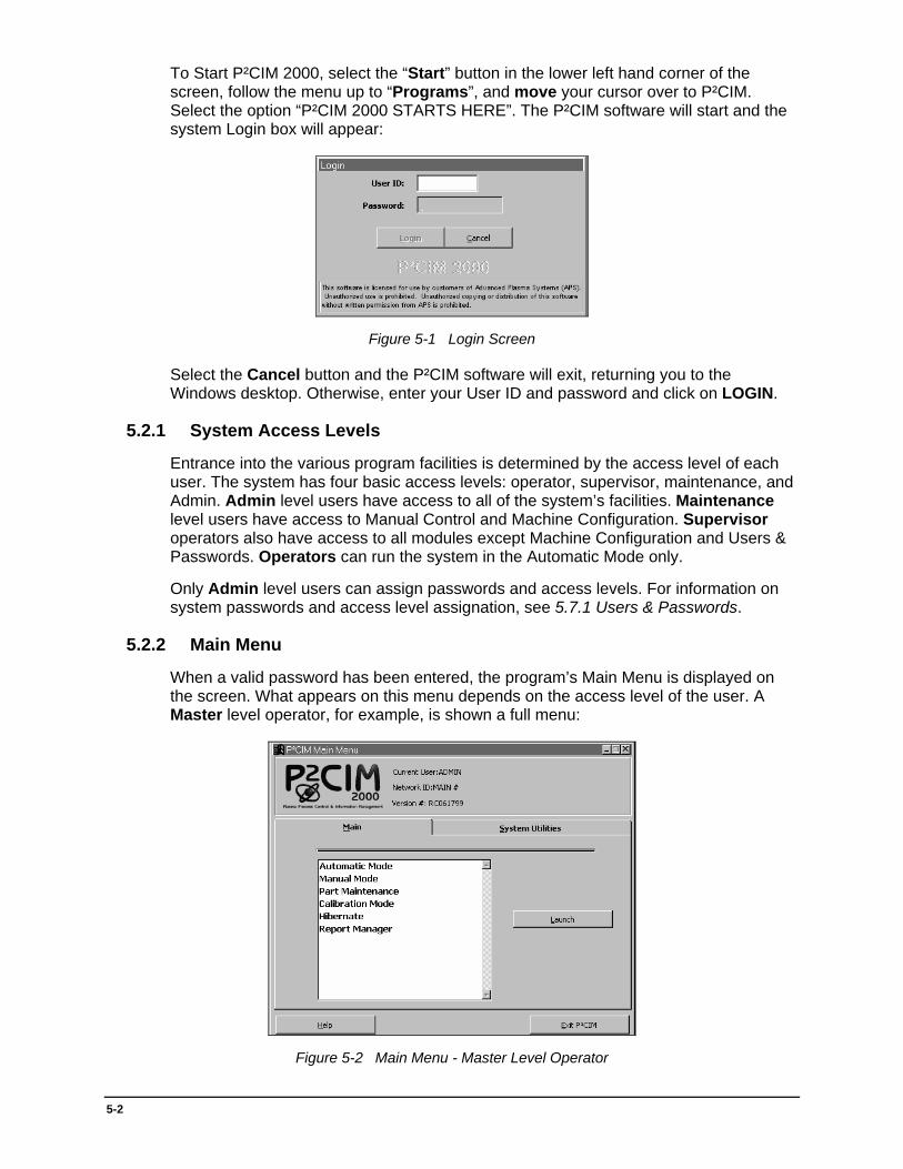
To Start P²CIM 2000, select the “Start” button in the lower left hand corner of the screen, follow the menu up to “Programs”, and move your cursor over to P²CIM. Select the option “P²CIM 2000 STARTS HERE”. The P²CIM software will start and the system Login box will appear:
Figure 5-1 Login Screen
Select the Cancel button and the P²CIM software will exit, returning you to the Windows desktop. Otherwise, enter your User ID and password and click on LOGIN.
5.2.1 System Access Levels
Entrance into the various program facilities is determined by the access level of each user. The system has four basic access levels: operator, supervisor, maintenance, and Admin. Admin level users have access to all of the system’s facilities. Maintenance level users have access to Manual Control and Machine Configuration. Supervisor operators also have access to all modules except Machine Configuration and Users & Passwords. Operators can run the system in the Automatic Mode only.
Only Admin level users can assign passwords and access levels. For information on system passwords and access level assignation, see 5.7.1 Users & Passwords.
5.2.2 Main Menu
When a valid password has been entered, the program’s Main Menu is displayed on the screen. What appears on this menu depends on the access level of the user. A Master level operator, for example, is shown a full menu:
Figure 5-2 Main Menu - Master Level Operator
5-3
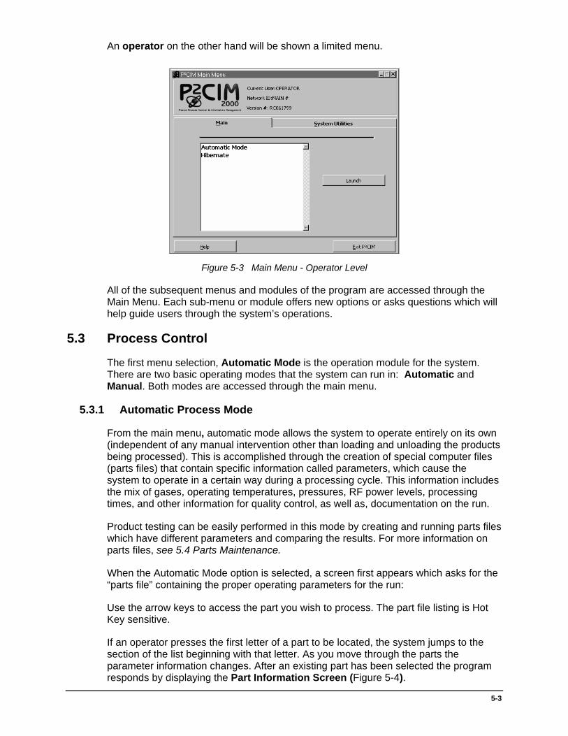
An operator on the other hand will be shown a limited menu.
Figure 5-3 Main Menu - Operator Level
All of the subsequent menus and modules of the program are accessed through the Main Menu. Each sub-menu or module offers new options or asks questions which will help guide users through the system’s operations.
5.3 Process Control
The first menu selection, Automatic Mode is the operation module for the system. There are two basic operating modes that the system can run in: Automatic and Manual. Both modes are accessed through the main menu.
5.3.1 Automatic Process Mode
From the main menu, automatic mode allows the system to operate entirely on its own (independent of any manual intervention other than loading and unloading the products being processed). This is accomplished through the creation of special computer files (parts files) that contain specific information called parameters, which cause the system to operate in a certain way during a processing cycle. This information includes the mix of gases, operating temperatures, pressures, RF power levels, processing times, and other information for quality control, as well as, documentation on the run.
Product testing can be easily performed in this mode by creating and running parts files which have different parameters and comparing the results. For more information on parts files, see 5.4 Parts Maintenance.
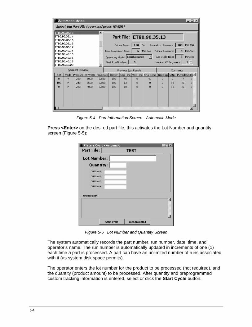
When the Automatic Mode option is selected, a screen first appears which asks for the “parts file” containing the proper operating parameters for the run:
Use the arrow keys to access the part you wish to process. The part file listing is Hot Key sensitive.
If an operator presses the first letter of a part to be located, the system jumps to the section of the list beginning with that letter. As you move through the parts the parameter information changes. After an existing part has been selected the program responds by displaying the Part Information Screen (Figure 5-4).
5-4
Figure 5-4 Part Information Screen - Automatic Mode
Press <Enter> on the desired part file, this activates the Lot Number and quantity screen (Figure 5-5):
Figure 5-5 Lot Number and Quantity Screen
The system automatically records the part number, run number, date, time, and operator’s name. The run number is automatically updated in increments of one (1) each time a part is processed. A part can have an unlimited number of runs associated with it (as system disk space permits).
The operator enters the lot number for the product to be processed (not required), and the quantity (product amount) to be processed. After quantity and preprogrammed custom tracking information is entered, select or click the Start Cycle button.
5-5
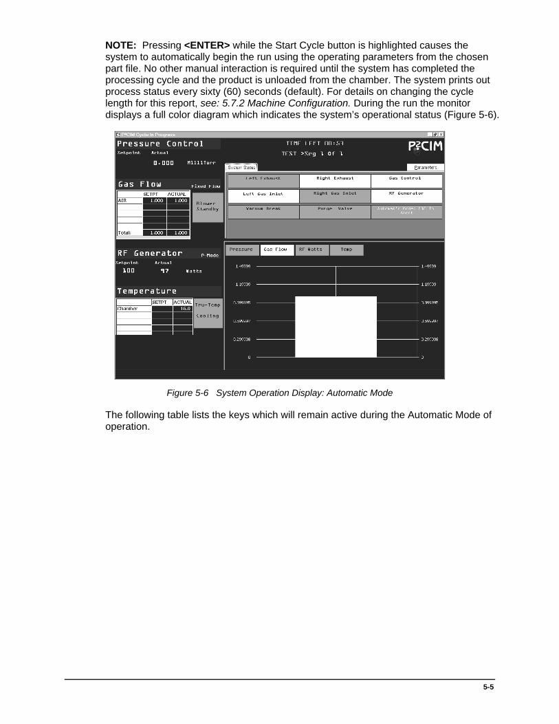
NOTE: Pressing <ENTER> while the Start Cycle button is highlighted causes the system to automatically begin the run using the operating parameters from the chosen part file. No other manual interaction is required until the system has completed the processing cycle and the product is unloaded from the chamber. The system prints out process status every sixty (60) seconds (default). For details on changing the cycle length for this report, see: 5.7.2 Machine Configuration. During the run the monitor displays a full color diagram which indicates the system’s operational status (Figure 5-6).
Figure 5-6 System Operation Display: Automatic Mode
The following table lists the keys which will remain active during the Automatic Mode of operation.
5-6
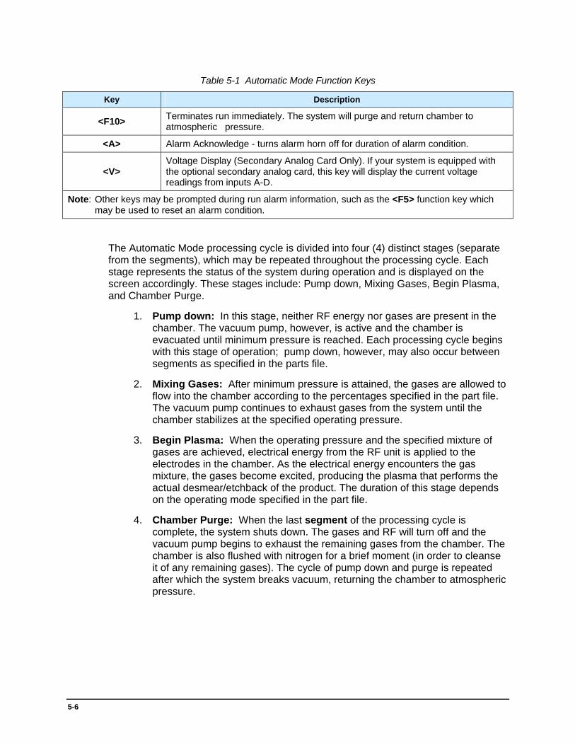
Table 5-1 Automatic Mode Function Keys
Key Description
<F10> Terminates run immediately. The system will purge and return chamber to atmospheric pressure.
<A> Alarm Acknowledge - turns alarm horn off for duration of alarm condition.
<V> Voltage Display (Secondary Analog Card Only). If your system is equipped with the optional secondary analog card, this key will display the current voltage readings from inputs A-D.
Note: Other keys may be prompted during run alarm information, such as the <F5> function key which may be used to reset an alarm condition.
The Automatic Mode processing cycle is divided into four (4) distinct stages (separate from the segments), which may be repeated throughout the processing cycle. Each stage represents the status of the system during operation and is displayed on the screen accordingly. These stages include: Pump down, Mixing Gases, Begin Plasma, and Chamber Purge.
1. Pump down: In this stage, neither RF energy nor gases are present in the chamber. The vacuum pump, however, is active and the chamber is evacuated until minimum pressure is reached. Each processing cycle begins with this stage of operation; pump down, however, may also occur between segments as specified in the parts file.
2. Mixing Gases: After minimum pressure is attained, the gases are allowed to flow into the chamber according to the percentages specified in the part file. The vacuum pump continues to exhaust gases from the system until the chamber stabilizes at the specified operating pressure.
3. Begin Plasma: When the operating pressure and the specified mixture of gases are achieved, electrical energy from the RF unit is applied to the electrodes in the chamber. As the electrical energy encounters the gas mixture, the gases become excited, producing the plasma that performs the actual desmear/etchback of the product. The duration of this stage depends on the operating mode specified in the part file.
4. Chamber Purge: When the last segment of the processing cycle is complete, the system shuts down. The gases and RF will turn off and the vacuum pump begins to exhaust the remaining gases from the chamber. The chamber is also flushed with nitrogen for a brief moment (in order to cleanse it of any remaining gases). The cycle of pump down and purge is repeated after which the system breaks vacuum, returning the chamber to atmospheric pressure.

5-7
In addition to these four (4) stages there is also a Holding status. Holding occurs during the Begin Plasma stage if the conditions in the chamber go out of tolerance from the parameters specified in the parts file (pump or board temperature too high, improper gas flow, or too high/low pressure). The system then suspends plasma processing by shutting off RF energy, and attempts to stabilize conditions inside the chamber. If stabilization is achieved, the RF is reactivated and processing continues. If conditions cannot be stabilized, the operator may terminate the processing cycle by pressing <F10> key or try to stabilize again by pressing <F5> key.
When the system has completed the operating cycle an End Process Report is generated. This report contains the results of the run. In particular, it will contain the part number, run number, date, time of processing, operator name, lot number, quantity of parts, the minimum pressure achieved, pump down time during the first segment, the total run time for all segments, and the final temperature achieved at the end of the last segment. It also provides a list of numeric error codes corresponding to any errors that may have occurred during the run.
At the end of the run, the time and existing conditions when the error occurred will be printed automatically.
After the cycle is complete, the program asks for a Run Description. At this time any information needed to describe the run may be entered. When a description has been typed, the operator must press the <TAB> key to exit the run description box. The system will print an end of cycle report (default). The operator can either start another run of the same part by simply re-selecting the Start Cycle button or the operator can select Lot Complete and return to the part selection screen.
Hint: Pressing <Esc> will function as if Lot Complete has been selected. The indicator LEDs on the printer should be checked to make sure it is ready to print. When any key is pressed, the program prints a report similar to the following sample:
Figure 5-7 Sample Report

5-8
The program then returns to the initial Process Part screen where a new part number can be selected for processing. Table 5-2 provides definitions for terms used in End Process Report.

5-9
Table 5-2 - End Process Report Keywords
Item Description
Part number
The name assigned to the parts file. A part name may be up to fifteen (15) characters in length. Note: Use only alphanumeric characters to name parts files. Other characters, such as @ ! # $ % ^ will not be accepted as valid characters for part names.
Run Number A numeric record of the processing runs where the parts file was used to control the system. The program automatically increases the number by one (1) each time the part file is used.
Date Automatically supplied by the computer.
Time The time the run was started. Automatically supplied by the computer.
Operator The current operator’s name is automatically keyed to all appropriate process information through the user’s password.
Lot Number Reserved for product record keeping. The information is entered optionally by the operator during the creation of the parts file.
5-10
Table 5-2 - End Process Report Keywords (Continued)
Item Description
Quantity The amount of product that is processed. This number is supplied by the operator during the creation of the parts file.
Error Codes Numerical listing of any processing errors encountered during system operation. See 5.8.1 List of Reports to print a list of error messages which correspond to the numeric codes.
Minimum Pressure (expressed in
millitorr)
The lowest pressure the system achieves before releasing the gases into the chamber. The system initially pumps down to this pressure in order to rid the chamber of any atmospheric or processing gases that may be left from previous operating runs. In effect, this initial pump down cleans out the chamber and creates a fresh starting point for each batch. The pressure, however, will change as processing continues, as specified by the operating pressure of each segment.
Pump Time During first segment, amount of time the vacuum pump takes to exhaust the chamber to minimum pressure.
Run Time The amount of time that RF energy is present in the chamber.
Final Temperature (in Celsius degrees)
The temperature of the chamber (at the end of the last segment) of the operating run. This figure is included in order to determine the etch rate of the product by comparing this temperature to the initial chamber temperature. Heat rise is critical to etch rate.
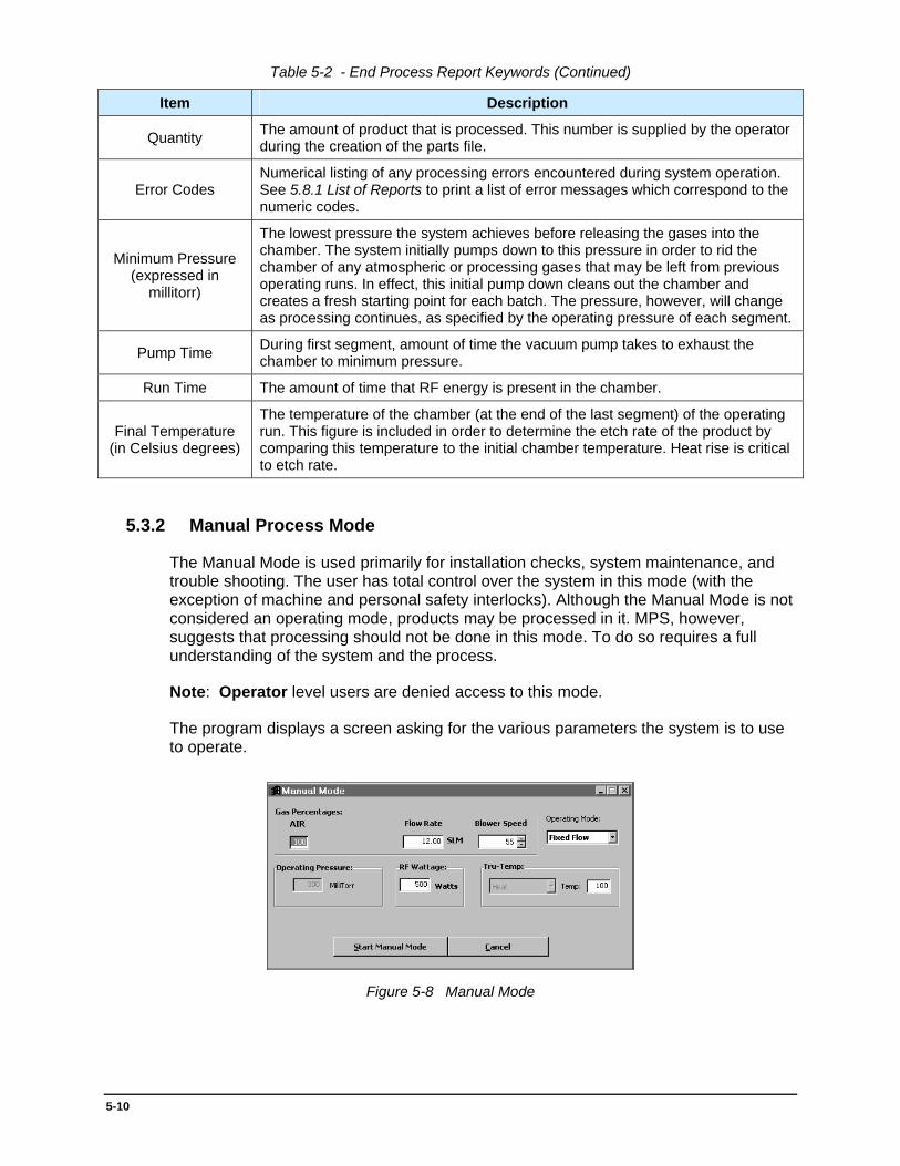
5.3.2 Manual Process Mode
The Manual Mode is used primarily for installation checks, system maintenance, and trouble shooting. The user has total control over the system in this mode (with the exception of machine and personal safety interlocks). Although the Manual Mode is not considered an operating mode, products may be processed in it. MPS, however, suggests that processing should not be done in this mode. To do so requires a full understanding of the system and the process.
Note: Operator level users are denied access to this mode.
The program displays a screen asking for the various parameters the system is to use to operate.
Figure 5-8 Manual Mode

5-11
The first parameters entered are the gas percentages. These are merely the amounts of each gas to be used during a processing run. The total percentage for all gases must equal 100%. The operator keys in the percentage for each gas and presses the <Enter> key. If invalid percentages are entered, the program displays an appropriate error message and asks for the percentage of the gases to be re-entered.
The operating mode is the next parameter to be entered. The operating mode specifies how both the pressure and flow of gases are to be maintained in the chamber during processing.
The options that are displayed for this parameter depend on whether or not the system is equipped with a blower speed controller.
If the “M” mode is specified for Mass Flow, the system will maintain a constant operating pressure during processing by varying the amount of gases entering the chamber at the flow controllers. When selected the program responds by asking for the operating pressure and the amount of RF energy to be applied to the electrodes.
If “F” is specified for Fixed Flow, the system will maintain a fixed rate of flow (SLM) for each gas by varying the chamber pressure. When this option is chosen the program asks for an amount of RF power and the total SLM of flow for the gases.
If “C” Conductance Mode is selected (systems equipped with a speed controller only), the system maintains a constant pressure and SLM of gas flow by varying the percent speed of the blower speed controller, thus varying the amount of total gas flow being evacuated from the chamber. When this option is selected, the program responds by asking for the operating pressure, RF power, and total SLM of flow to the chamber.
The operating pressure parameter (in millitorr) represents the pressure maintained in the chamber during processing. The maximum pressure which can be entered is 500mT.
The RF power parameter represents the amount of electrical energy applied to the electrodes during processing. The maximum amount of RF power that can be entered depends on the model of the system. In general, the system is seldom run at greater than 80% of full power. If an excessively high power level is entered, the program will flash an error message and prompt the user to re-enter that parameter.
The Total SLM parameter specifies the total flow of gas into the chamber through the mass flow controllers in standard liters per minute. The maximum amount of flow which can be entered varies with the model and pump configuration. If an excessive amount is entered, the system will display an error message and ask for the SLM flow to be re-entered.
When the Start Manual Mode button is pressed, the system begins processing run in the Manual Mode. During the run the monitor displays a full color diagram indicating the system’s operational status (Figure 5-9).

5-12
Figure 5-9 System Operation Display - Manual Mode
The box at the right top side of the screen (under “System Status”) refers to the function keys on the keyboard. By manipulating these keys, the various system operations may be checked out quickly and easily for troubleshooting or maintenance. When a key is pressed, its corresponding numbered box on the screen lights up in green, indicating the particular function that has been chosen. The affected area of the system (which the key controls) is also displayed on the screen. Table 5-3 lists the functions of each key.
Hint: The items may also be clicked with the mouse to activate the desired function.
Table 5-3 Manual Mode Function Keys
Function Key Description
<F1> Opens/closes left exhaust valve.
<F2> Opens/closes right exhaust valve.
<F3> Opens/closes left gas inlet.
<F4> Opens/closes right gas inlet.
<F5> Turns RF power on or off.
<F6> Turns On or Off gas flow.
<F7> Tests alarm.
<F8> Opens/closes gas supply used to purge the chamber.
<F9> Opens/closes vacuum break.
<F10> or <END> Exits manual mode.
5-13
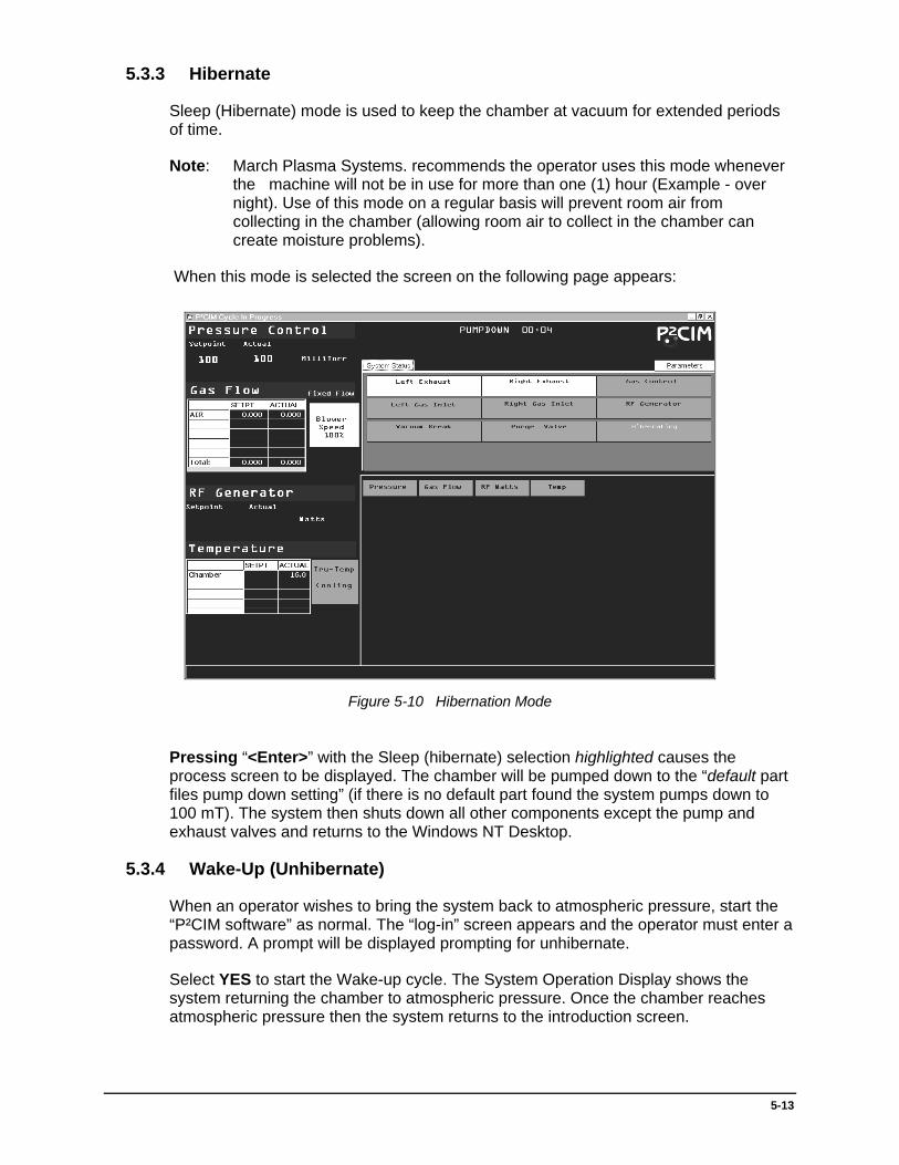
5.3.3 Hibernate
Sleep (Hibernate) mode is used to keep the chamber at vacuum for extended periods of time.
Note: March Plasma Systems. recommends the operator uses this mode whenever the machine will not be in use for more than one (1) hour (Example - over night). Use of this mode on a regular basis will prevent room air from collecting in the chamber (allowing room air to collect in the chamber can create moisture problems).
When this mode is selected the screen on the following page appears:
Figure 5-10 Hibernation Mode
Pressing “<Enter>” with the Sleep (hibernate) selection highlighted causes the process screen to be displayed. The chamber will be pumped down to the “default part files pump down setting” (if there is no default part found the system pumps down to 100 mT). The system then shuts down all other components except the pump and exhaust valves and returns to the Windows NT Desktop.
5.3.4 Wake-Up (Unhibernate)
When an operator wishes to bring the system back to atmospheric pressure, start the “P²CIM software” as normal. The “log-in” screen appears and the operator must enter a password. A prompt will be displayed prompting for unhibernate.
Select YES to start the Wake-up cycle. The System Operation Display shows the system returning the chamber to atmospheric pressure. Once the chamber reaches atmospheric pressure then the system returns to the introduction screen.

5-14
5.4 Parts Maintenance
The Parts File Maintenance module controls the display, creation and maintenance of process control information. This is information that specifies how the equipment has operated or will operate during a processing cycle. The information is stored in computer files called Parts Files. A parts file is usually created for each type of product to be processed and may be used for an unlimited number of runs. Besides containing process control information, parts files also assist in quality control by automatically keeping a record on each run where the part was used. When chosen, the Part File Maintenance (Figure 5-11) menu first appears:
Figure 5-11 Part File Maintenance Menu
Note: Only Admin, Maintenance and Supervisor level operators can access the delete part file option. Operator level users are permitted to view the parts directory and view a part and its runs. A limited menu showing only these options appears for such operators.
5.5 Parts File
5.5.1 Parts File Parameters
1. Part Number
The name assigned to the parts file. It can be up to fifteen (15) characters in length, and contain any alphanumeric letters or numbers.
Note: Use ONLY alphanumeric characters to name parts files. Other characters, such as @ ! # $ % ^ will not be accepted as valid characters for part names.
CAUTION! Under NO circumstance should a comma (,) be used in a part name. The presence of a comma in a parts file can cause PROGRAM FAILURE when the part is used during a processing cycle!
2. Critical Temperature (expressed in centigrade)

5-15
The highest temperature the part is allowed to reach during processing. The final temperature should always be lower than the critical temperature.
When a part reaches this setting, the system will sound an alarm to warn the operator and begin a five (5) minute cool down cycle. During this cycle the RF shuts off. After five (5) minutes the alarm is reset, the RF is re-activated and plasma continues (the alarm horn sounds during the entire five (5) minute cool down - to shut off horn, for this alarm, press the <A> key).
3. Pump Down (expressed in millitorr; 1 millitorr = 1 micron)
The lowest pressure the system achieves before releasing gases into the chamber. The system initially pumps down to this pressure in order to rid the chamber of any atmospheric or processing gases. In effect, this initial pump down cleans out the chamber and creates a fresh starting point for each batch to be processed. The pressure, however, will change as processing continues (as specified by the operating pressure for each processing segment).
4. Maximum Pump Time (expressed in minutes)
The time allotted for the vacuum pump to exhaust the chamber to minimum pressure. If the time allotted is exceeded, an error message is displayed and the alarm sounds. The error message asks if the process is to continue. Pressing <F5> starts the processing run at the pressure achieved to that point. <F10> aborts the run.
5. Gas Cycle Time (expressed in minutes or seconds)
The time allotted for the gases to flow through the chamber in one direction before being reversed. The gas flow is reversed periodically during the processing cycle to ensure uniform results in the etch of the product. Some chambers are constructed with gas manifolds in the chamber. In this case, both inlets and exhausts are “ON” simultaneously. Refer to 5.7.2 Machine Configuration for instructions to change between minutes and seconds.
6. Operating Mode
The operating mode specifies how both the pressure and flow of gases are to be maintained in the chamber during processing. There are three (3) operating modes which the system can run in:
• F - Fixed Flow - A fixed SLM for each gas is maintained by varying the chamber pressure. The program requests the total SLM of flow to be specified when this option is chosen.
• M - Mass Flow - In this mode, a constant operating pressure is maintained by using the flow controllers to vary the amount of gases entering the chamber. When this option is selected the program requests the operating pressure for each segment displayed.
Note: On systems equipped with a blower speed controller the blower will be fixed at 100% for both Fixed and Mass Flow modes.
• C - Conductance Mode. This mode applies ONLY to systems equipped with a blower speed controller. Here, a constant pressure and SLM of gas flow are specified. The pressure is maintained by varying the blower speed, thus controlling the chamber pressure.

5-16
7. Number Of Segments
Processing runs may be divided into a total of ten (10) segments, each segment containing different processing parameters. Dividing runs allows increased flexibility in the way the products are to be processed. For example, the first segment may be used as a simple warm-up run (in order to bring the products to the proper processing temperature). Here the system is run in the “V” mode allowing the chamber to heat to the temperature specified in the segment. When this temperature is achieved, the system automatically moves to the next segment where the actual processing of the boards begins (with new gas percentages and a new operating pressure). Other segments might contain entirely new processing parameters to further enhance the final results of the product.
8. Next Run Number
Run numbers are sequentially numbered for each run beginning with the number 1 for the first run on any part. When creating a new part an operator may choose to change this beginning number for that part. The field cannot be changed once runs have been made on a part. This feature is intended to be used by operators who have archived and deleted a part and wish to re-create the same part for continued use, thus allowing them to continue with the previous number scheme.
After the “Number Of Segments” section has been entered the operator is automatically presented the Segment Editor (Figure 5-12). Since there are many functions P²CIM has the capacity for, the wizard will walk the user through configuring the segments one by one to ensure proper desired segment operation. The options presented within this wizard are described below in detail.
Figure 5-12 Segment Editor
9. Gas Percentages

5-17
The system has the option of including up to five (5) gases. However, there are three (3) basic gases which are almost always used in the process: oxygen (O2) nitrogen (N2), and tetrafluoromethane (CF4). Any percentage for any gas may be entered, but the total percentage for all the gases must equal 100%. Gas percentages are entered for each segment and may be changed as required for each phase of the processing run.
10. Operating Pressure
Specifies the pressure the chamber will maintain in each segment of an operating run. This parameter is specified when the operating mode is set to either "M" or "C" (the latter setting pertaining to blower speed controller systems only but is not specified in the "F" mode).
11. Control Mode
Specifies how the power level and final temperature are to be maintained during each segment of the run. Control mode settings include:
P - Power Mode. In this setting, a specific power level is maintained in the chamber. This option is used mainly to achieve a certain etch rate in the final product (since the amount of RF energy present in the chamber determines the degree to which the product is etched and desmeared). The final temperature is not specified in this mode. The power level is maintained over a fixed interval as specified in each segment. The segment ends when the time interval has elapsed.
O - Power Mode (operator entered run time). This setting is nearly identical to the “P” mode of operation (with the exception that the operator is prompted for the segment time before the segment begins).
V - Variable Mode. In this setting the system attempts to run at a specified power level until the final temperature is achieved. No time interval is specified. Once the temperature is achieved the system moves on to the next segment. This mode is particularly useful for warm-up runs.
D - Dwell Mode. The system will maintain vacuum without RF energy (no plasma). This mode is used to hold parts at vacuum for a segment or to "soak" parts in a gas prior to processing.
C - Custom Mode (Secondary Analog Card Only). If your system is equipped with a secondary analog card, this option allows you to trigger the end of the segment based upon external voltage readings, time, and/or temperature. For example, an end of roll signal may send 5VDC when the end of material has been reached. This input can be used to trigger the end of the segment.
12. TRU-Temp
Specifies the desired control mode for the “Tru-Temp” electrode control circuit. To use this option, your system must be equipped with Tru-Temp electrodes and have the option enabled under “Machine Set-Up” (Section 4.5.2). Valid options are: “C” for cooling mode, “H” for heating mode, and “D” for the disable mode.
13. Temp Set
Specifies the temperature for Tru-Temp control (if enabled). If Tru-Temp is disabled, this option is skipped.
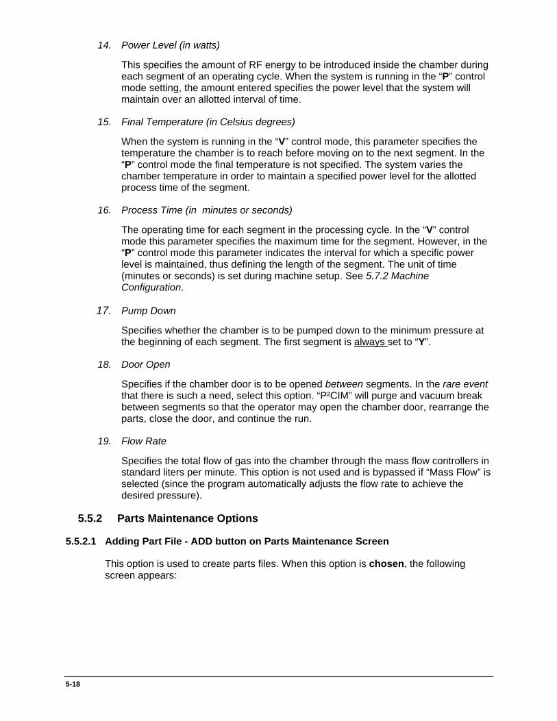
5-18
14. Power Level (in watts)
This specifies the amount of RF energy to be introduced inside the chamber during each segment of an operating cycle. When the system is running in the “P” control mode setting, the amount entered specifies the power level that the system will maintain over an allotted interval of time.
15. Final Temperature (in Celsius degrees)
When the system is running in the “V” control mode, this parameter specifies the temperature the chamber is to reach before moving on to the next segment. In the “P” control mode the final temperature is not specified. The system varies the chamber temperature in order to maintain a specified power level for the allotted process time of the segment.
16. Process Time (in minutes or seconds)
The operating time for each segment in the processing cycle. In the “V” control mode this parameter specifies the maximum time for the segment. However, in the “P” control mode this parameter indicates the interval for which a specific power level is maintained, thus defining the length of the segment. The unit of time (minutes or seconds) is set during machine setup. See 5.7.2 Machine Configuration.
17. Pump Down
Specifies whether the chamber is to be pumped down to the minimum pressure at the beginning of each segment. The first segment is always set to “Y”.
18. Door Open
Specifies if the chamber door is to be opened between segments. In the rare event that there is such a need, select this option. “P²CIM” will purge and vacuum break between segments so that the operator may open the chamber door, rearrange the parts, close the door, and continue the run.
19. Flow Rate
Specifies the total flow of gas into the chamber through the mass flow controllers in standard liters per minute. This option is not used and is bypassed if “Mass Flow” is selected (since the program automatically adjusts the flow rate to achieve the desired pressure).
5.5.2 Parts Maintenance Options
5.5.2.1 Adding Part File - ADD button on Parts Maintenance Screen
This option is used to create parts files. When this option is chosen, the following screen appears:

5-19
Figure 5-13 Adding a Part File
To create a part the operator enters a unique part name and presses the <Enter> key. A part name can have up to fifteen (15) alphanumeric characters.
NOTE: Use ONLY alphanumeric characters to name parts files. Other characters, such as @ ! # $ % ^ will not be accepted as valid characters for part names.
The system then checks the name entered to make sure it is unique and an error message displays if the part name already exists. The user may begin to step through the configuration options for this new part file and modify them as necessary. The user should press the Save button to save the new part file to disk. The Cancel button may also be used to discard the add operation.
Choosing the Copy option allows the parameters from an existing parts file to be used to create a new file (the current highlighted part file is used for the copy). Any existing parts file can be used to supply the parameters. When this is selected the system copies the parameters from the currently selected part onto the Part Information screen.
Note: For more information on the parameters used in parts files, see Table 5-5.
When the last parameter has been edited or bypassed, press the “SAVE” button at the top left corner of the part file screen. The screen then returns to the view part file screen. The operator may choose to enter another new part to or exit to the parts maintenance main menu. To exit the screen press the <ESC> key.
5.5.2.2 Delete Part File(s)
Selecting Delete Part File(s) from the Part Maintenance Screen allows parts files to be deleted. Only Admin and Supervisor operator level users can delete parts files. When this option is selected the program displays a Confirm Delete box (Figure 5-14) confirming the part file to delete.

5-20
Figure 5-14 Confirm Delete
CAUTION! All stored runs associated with this part will also be deleted. Consider using the archive option before deleting Part File(s).
To delete several part files, hold down the “SHIFT” key and select a part. Then release the “SHIFT” key. The Parts Maintenance Screen will now enter ‘Multi-Select Mode’. You may then hold down the <CTRL> key and click the individual part file(s) to delete. When you have made your selections, press the “DELETE” button to remove them from the system.
5.5.2.3 View/Edit Parts
From the Parts Maintenance Menu, View mode is the initial mode of this screen. Parts files with no associated runs can also be edited from this screen by selecting the Edit button or pressing the <Enter> key when the desired part is highlighted. When selected, the following screen appears:
Figure 5-15 Parts File Maintenance Screen
If a user attempts to edit a part with runs attached, the following message appears:
Figure 5-16 Edit Error Message
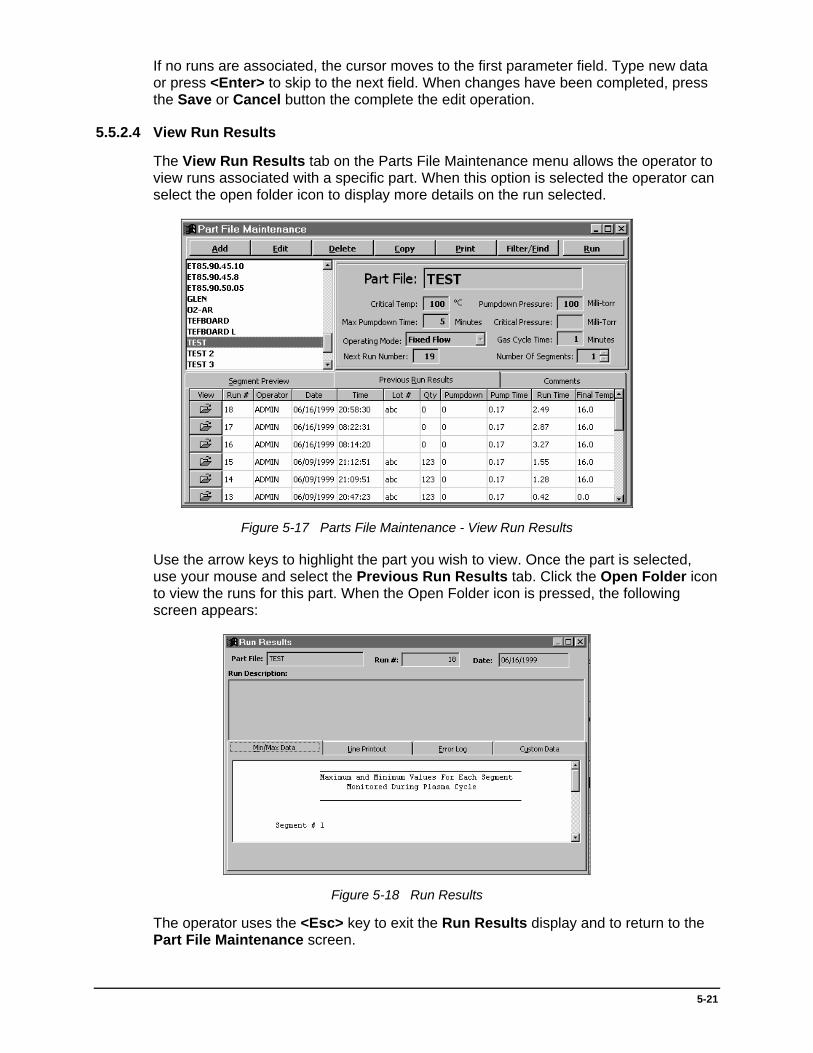
5-21
If no runs are associated, the cursor moves to the first parameter field. Type new data or press <Enter> to skip to the next field. When changes have been completed, press the Save or Cancel button the complete the edit operation.
5.5.2.4 View Run Results
The View Run Results tab on the Parts File Maintenance menu allows the operator to view runs associated with a specific part. When this option is selected the operator can select the open folder icon to display more details on the run selected.
Figure 5-17 Parts File Maintenance - View Run Results
Use the arrow keys to highlight the part you wish to view. Once the part is selected, use your mouse and select the Previous Run Results tab. Click the Open Folder icon to view the runs for this part. When the Open Folder icon is pressed, the following screen appears:
Figure 5-18 Run Results
The operator uses the <Esc> key to exit the Run Results display and to return to the Part File Maintenance screen.

5-22
5.5.2.5 Archive Part File (s)
Archive Part File(s) allows the operator to save part files and their associated runs to another drive. When this option is selected the following screen appears:
Figure 5-19 Parts File Archive/Restore
After selecting the Next button, the following Part File selection box appears:
Figure 5-20 Parts File Selection Screen
The operator may select only the parts to be archived by filling in the Value field with only the Part File name to be archived and selecting Query to the desired part(s). After pressing query the operator may choose to archive run file(s). These files contain the line-by-line report used to generate the end of process graph. Each graph log is stored separately by date and time of run. Select Finish and the archive process begins. The archive process may take a long time depending on the volume of run information. When complete, the operator will be prompted for a destination directory for the archive file.
Any available drive and directory may be selected (Example- A:, B:, or a network drive). The archived file created has the name ARCHIVE.ZIP. Each time parts are archived a new directory should be created by the operator to avoid overwriting an existing archive.
The operator may choose to place either a pre-formatted floppy disk in the A: or B: drives or have the system format the disk (My Computer, Right Click “A”, select Format).

5-23
This archived file is a copy of those on the system. The parts and runs still remain on the hard drive. See 5.5.2.2 Delete Part File(s) to remove parts from the system.
5.5.2.6 Restore from Archives
Restore from Archives allows parts (which have been archived) to be restored to the hard drive. This option works directly opposite of the Archive function. When Restore is selected, the operator is prompted for the location of the ARCHIVE.ZIP file that the archive function created.
Select the drive and directory where the archived parts are stored. The system will bring up the query box described in 5.5.2.5 Archive Part File (s). If the operator selects the All button, then all archive parts are extracted for restoring. The operator may define limiting criteria to restore only a single part or a limited set of parts.
The system will display a list of the archived parts selected for restore before the operation begins. Once the operator selects the Finish button, the restore process begins.
Note: The part files to be restored must not match the name of an existing part file on the system. If this occurs a brief message will appear on the screen stating that “the part was skipped” and the system will go on to the next part to be restored. However, run information (if selected) will be restored, provided that it does not conflict with existing entries.
When all parts have been restored, the system displays the message Restore Complete. Press <Enter> to clear this message and return to the main menu.
5.6 Calibration/Testing
From the main menu, Calibration Mode allows the operator to perform system calibration. Only personnel with Admin and Maintenance level passwords may access this mode.
Note: Calibration adjustment values cannot exceed +/- 10 percent of factory calibration (20% for pressure). If system is more than 10% off factory calibration this indicates a problem. Do not adjust system calibration to solve these problems, contact an MPS Service Technician.
5.6.1 Calibration Mode
When Calibration Mode is selected, the “last set manual mode parameters” are displayed on screen:
Press <Enter> to Start Calibration Mode. The system operation display appears. At the left of the screen is a list of function keys for manual control of the machine.
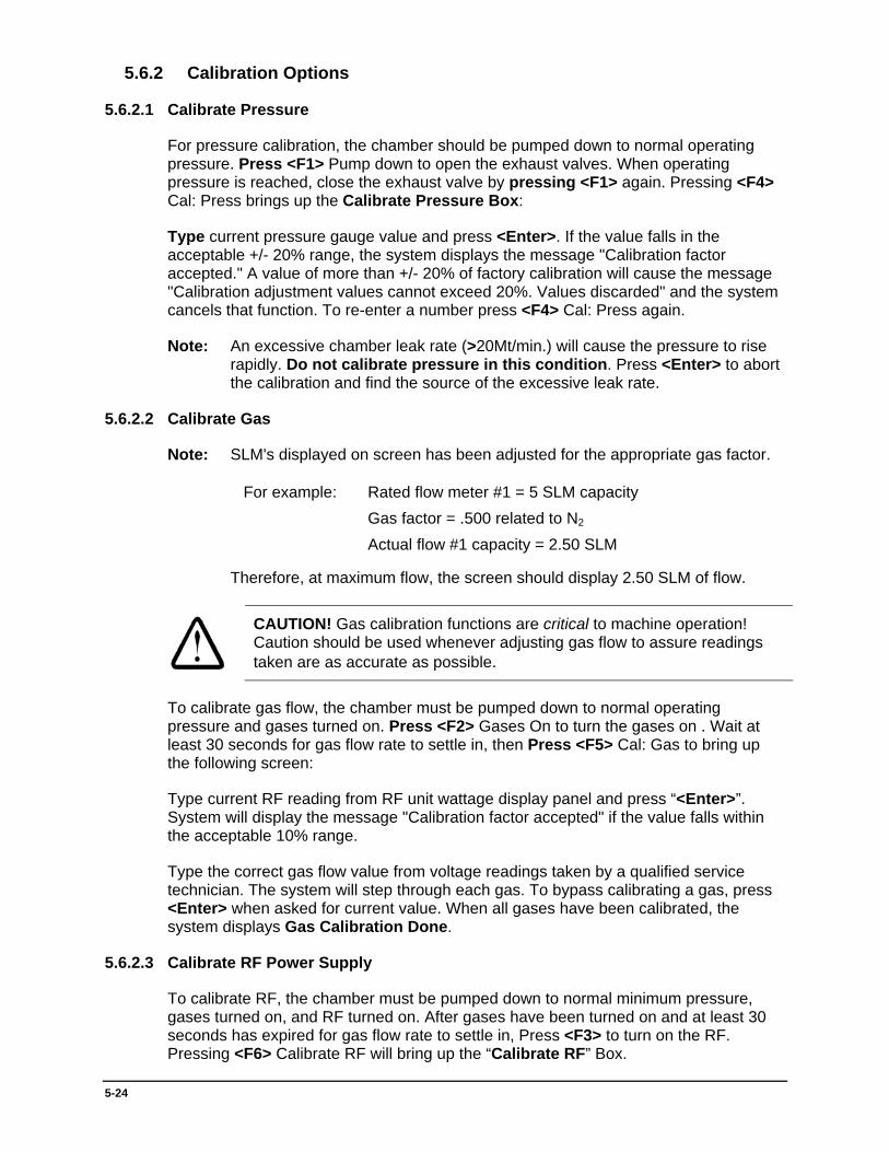
5-24
5.6.2 Calibration Options
5.6.2.1 Calibrate Pressure
For pressure calibration, the chamber should be pumped down to normal operating pressure. Press <F1> Pump down to open the exhaust valves. When operating pressure is reached, close the exhaust valve by pressing <F1> again. Pressing <F4> Cal: Press brings up the Calibrate Pressure Box:
Type current pressure gauge value and press <Enter>. If the value falls in the acceptable +/- 20% range, the system displays the message "Calibration factor accepted." A value of more than +/- 20% of factory calibration will cause the message "Calibration adjustment values cannot exceed 20%. Values discarded" and the system cancels that function. To re-enter a number press <F4> Cal: Press again.
Note: An excessive chamber leak rate (>20Mt/min.) will cause the pressure to rise rapidly. Do not calibrate pressure in this condition. Press <Enter> to abort the calibration and find the source of the excessive leak rate.
5.6.2.2 Calibrate Gas
Note: SLM's displayed on screen has been adjusted for the appropriate gas factor.
For example: Rated flow meter #1 = 5 SLM capacity Gas factor = .500 related to N2 Actual flow #1 capacity = 2.50 SLM
Therefore, at maximum flow, the screen should display 2.50 SLM of flow.
CAUTION! Gas calibration functions are critical to machine operation! Caution should be used whenever adjusting gas flow to assure readings taken are as accurate as possible.
To calibrate gas flow, the chamber must be pumped down to normal operating pressure and gases turned on. Press <F2> Gases On to turn the gases on . Wait at least 30 seconds for gas flow rate to settle in, then Press <F5> Cal: Gas to bring up the following screen:
Type current RF reading from RF unit wattage display panel and press “<Enter>”. System will display the message "Calibration factor accepted" if the value falls within the acceptable 10% range.
Type the correct gas flow value from voltage readings taken by a qualified service technician. The system will step through each gas. To bypass calibrating a gas, press <Enter> when asked for current value. When all gases have been calibrated, the system displays Gas Calibration Done.
5.6.2.3 Calibrate RF Power Supply
To calibrate RF, the chamber must be pumped down to normal minimum pressure, gases turned on, and RF turned on. After gases have been turned on and at least 30 seconds has expired for gas flow rate to settle in, Press <F3> to turn on the RF. Pressing <F6> Calibrate RF will bring up the “Calibrate RF” Box.

5-25
Type current RF reading from RF unit wattage display panel and press <Enter>. System will display the message "Calibration factor accepted." if the value falls within the acceptable 10% range.
5.6.2.4 Calibrate Temperature
Temperature calibration may be performed at any time (it is not necessary to have the chamber pumped down, gases turned on, or RF turned on). Pressing <F6> Calibrate Temp will bring up the Calibrate Temp Box. Type current temperature and press <Enter>.
Note: Actual temperature obtained for calibration should only be referenced from a factory certified manual temperature indicator.
5.6.2.5 N2 Purge
<F8> N2 Purge allows the operator to purge the chamber while in calibration mode. Press <F8> once to begin Nitrogen Purge. Press <F8> again to turn Purge off. Purging is not mandatory. An operator may exit the system without performing this operation.
5.6.2.6 Vacuum Break
<F9> Vac Break will break vacuum in the chamber. This is also a toggle function. Press <F9> once to begin vacuum break, again to stop.
5.6.2.7 Exit
<F10> Exit allows the operator to exit calibration mode. It is not necessary to purge the system or break vacuum before exiting. When this key is pressed, the system displays a box, asking the operator to save changes. Select “No” to discard changes or “Yes” to accept. System returns to the main menu.
NOTE: If the operator exits calibration mode with Gases or RF still on, the system safety procedure will be performed 10 seconds after exiting, returning all devices to Power Down state.
5.6.2.8 Reset Calibration
Reset calibration will allow the operator to reset all factors to factory calibrated settings. When selected the factory settings will appear on the screen.
Press “<Enter>” to set calibration factors back to factory calibrations shown on screen. When all factors have been reset the system returns to the main menu.
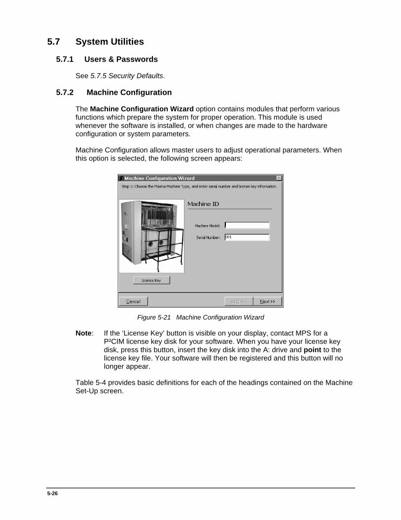
5-26
5.7 System Utilities
5.7.1 Users & Passwords
See 5.7.5 Security Defaults.
5.7.2 Machine Configuration
The Machine Configuration Wizard option contains modules that perform various functions which prepare the system for proper operation. This module is used whenever the software is installed, or when changes are made to the hardware configuration or system parameters.
Machine Configuration allows master users to adjust operational parameters. When this option is selected, the following screen appears:
Figure 5-21 Machine Configuration Wizard
Note: If the ‘License Key’ button is visible on your display, contact MPS for a P²CIM license key disk for your software. When you have your license key disk, press this button, insert the key disk into the A: drive and point to the license key file. Your software will then be registered and this button will no longer appear.
Table 5-4 provides basic definitions for each of the headings contained on the Machine Set-Up screen.

5-27
Table 5-4 System Master Keywords
Item Description
Machine Model Number
Machine Model number can be found on the plate attached to the side of the system.
Serial Number Serial Number can be found on the plate attached to the side of the machine
RF Capable Power The maximum RF power is the total amount of power the RF unit will output (as specified by the unit itself). See Table 5-5 for a list of maximum power levels for the RF units.
RF Cut-off Level
The RF cutoff is used to set an upper limit on the amount of RF power that can be entered during the creation of a parts file. The RF cutoff number entered here must be less than or equal to the maximum RF power. For example, if the RF cutoff is set for nine (9) kilowatts, any amount entered above this figure will cause the system to display an error message and prompts the user. o enter a new value (any number below nine (9) kilowatts will be accepted). Table 5-5 provides guidelines for setting the RF cutoff number.
Arc Count Level (1 - 90)
Specifies the number of RF arcs that are acceptable during the Arc timeframe period before an alarm condition is triggered.
NOTE: If these conditions occur, an alarm 27 Excessive RF arcing is registered. The RF is turned off, the alarm horn sounds, and the system waits for an operator response. The operator may press <F5> (retry) to continue the cycle or <F10> (abort).
Arc Timeframe (1 - 90) Timeframe in seconds after which the arc count level is reset.
Number of Gases Number of gas inlets connected to the system (must be configured for one to five (1-5) gases).
Number of Purges Number of purges to be performed at the end of an “Automatic Run” (this field may be set to zero (0) and the system will not perform a purge).
Purge Valve Open Time Length of time the purge valve should be opened.
Vacuum Break Time Length of time allowed for system to bring chamber back to atmospheric pressure.
End of Cycle Signal (Y/N)
System will sound three (3) beeps and at the end of the automatic cycle if set to yes.
Process Time In Determines what unit of measure is used for process time. Toggles between minutes and seconds.
Gas Type Type of gas attached to each flow controller.
Flow Rating (SLM) Factory Standard Liters per Minute is stamped on the side of each flow meter.
Gas Factor
A gas-dependent constant that is used for determining the actual volumetric flow rate of a gas through a controller. This constant depends on the density, specific heat, and molecular structure of the gas. The constant for nitrogen (N2) is “1.00”. The gas factor for other gases are relative to nitrogen. If additional gases are added, their conversion factors must be entered here as well. The “MKS Flow Controller Manual” includes a gas flow conversion chart (pages 6-3 and 6-4) which lists the conversion factors for a wide variety of gases.
Deviation Allowance Length of time (seconds) system will allow parameters to be out of tolerance before the alarm.

5-28
Table 5-4 System Master Keywords (Continued)
Item Description
Alarm Mode Tolerance
Percent deviation from tolerance before the alarm condition occurs (10% is recommended).
NOTE: If value is set too low the system will have false alarms. Setting the value too high will cause alarms not to sound when conditions go out of tolerance.
Blower Attached? Select 'Y' if system has a blower attached to the pump. The sensitivity of the Mass Flow mode is adjusted depending upon the selection of this option.
Blower On Pressure Used to set at what pressure the blower will start (in Torr).
Blower Speed Controller Determines if system has a Blower Speed Controller.
Tru-Temp Electrodes?
Select 'Y' if the system is equipped with Water Cooled/Heated electrodes and P²CIM will be maintaining the temperature. If chiller will be controlling the temperature, set to 'N' (Example - if chiller temperature is set to 15oC and desired electrode temperature is 30oC, the control valves would be required and this setting should be 'Y').
Temp Probe for Tru-Temp
Selects which thermocouple the program uses for Tru-Temp control. Systems may be equipped with up to four (4) thermocouples.
NOTE: The thermocouple selected must physically exist and be in working order, otherwise Tru-Temp control is automatically disabled.
Temperature Deadband
In order to eliminate constant cycling of the Tru-Temp control, the temperature will be allowed to operate within +/- degrees Celsius of this value.
Printer Detail On? Set 'Y' to print line by line report during process.
Printer Summary On? Prints Min./Max. Average and End of Run reports (if set to 'Y').
Disk Report On? Copies the “Automatic Process” line by line report to disk for storage. This report will be used to build the process graph.
Report Print Time This is the length of time between print cycles during a plasma process.
Disk Log Time Length of time between disk log entries (used for Autograph graphing).
Post Cycle Purges Post cycle purge is an option that helps cleanse the chamber of residual gases before the chamber door is opened.
Purge Count Controls the number of Post Cycle Purges.
Vacuum Break (Seconds)
To save time the chamber will not completely return to atmospheric pressure. Instead, P²CIM will only open the vacuum break valve for the number of seconds entered here to provide enough atmosphere into the chamber to help remove residual gases.
Blower Delay (Seconds)
For systems with the blower speed controller, the process of Post Cycle Purges can stress the blower and cause it to overload. This delay allows the blower enough time to settle before the Post Cycle Purge pump down begins. Setting this time too low may cause the blower to overload. If this problem occurs, increase the time specified in this field.
Pump down (Torr)
As with Vacuum Break, the system will not pump all the way down to save time. Instead, P²CIM will only evacuate the chamber to this value before beginning the next Post Cycle Purge. Once the last Post Cycle Purge has completed, the chamber is returned to atmospheric pressure and the door may be opened.
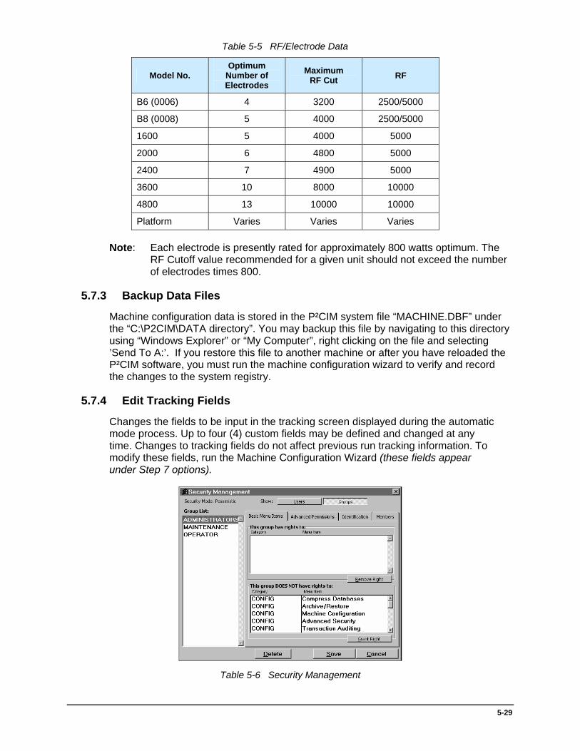
5-29
Table 5-5 RF/Electrode Data
Model No. Optimum
Number of Electrodes
Maximum RF Cut RF
B6 (0006) 4 3200 2500/5000
B8 (0008) 5 4000 2500/5000
1600 5 4000 5000
2000 6 4800 5000
2400 7 4900 5000
3600 10 8000 10000
4800 13 10000 10000
Platform Varies Varies Varies
Note: Each electrode is presently rated for approximately 800 watts optimum. The RF Cutoff value recommended for a given unit should not exceed the number of electrodes times 800.
5.7.3 Backup Data Files
Machine configuration data is stored in the P²CIM system file “MACHINE.DBF” under the “C:\P2CIM\DATA directory”. You may backup this file by navigating to this directory using “Windows Explorer” or “My Computer”, right clicking on the file and selecting ’Send To A:’. If you restore this file to another machine or after you have reloaded the P²CIM software, you must run the machine configuration wizard to verify and record the changes to the system registry.
5.7.4 Edit Tracking Fields
Changes the fields to be input in the tracking screen displayed during the automatic mode process. Up to four (4) custom fields may be defined and changed at any time. Changes to tracking fields do not affect previous run tracking information. To modify these fields, run the Machine Configuration Wizard (these fields appear under Step 7 options).
Table 5-6 Security Management

5-30
Type a name (up to 15 characters) for each field you wish to have entered in the tracking screen (lot number and quantity will appear in addition to the new fields). Any operator who has a tracking screen set to custom in their password set-up will be asked to enter these fields.
5.7.5 Security Defaults
This feature allows master level operators to change P²CIM's menu appearance and function. When Security Defaults is selected from the Utilities section of the Main Menu, the Configuration Options screen (Figure 5-22) opens.
Figure 5-22 Configuration Options
5.7.5.1 Pessimistic Security
Under this option new users will automatically be denied every access in P²CIM. A Master (ADMIN) level user must then log-in and explicitly give the user access to those modules that they deem necessary.
5.7.5.2 Optimistic Security
This option works the opposite of Pessimistic. When a new user is added to P²CIM they will be given system wide access to all modules (not recommended).
5.7.6 Advanced Security Setting
P²CIM now has a more powerful Security Manager than ever before. Users may be organized into groups and also may be assigned access based on individual qualifications.
5.7.6.1 Basic Menu Items
This option controls access to the individual screens and reports available. Each entry represents a module in P²CIM that the ‘group’ or ‘user’ has access to (depending on the currently selected Show option). To grant or revoke a module from a user, find the module in the box labeled ‘This group has rights to’ or ‘This group DOES NOT have rights to’. Select the option and press either the Grant Right or Remove Right button. The option then moves into the opposite category.

5-31
5.7.6.2 Advanced Permissions
This option configures powerful advanced security settings available within the modules themselves. This differs from ‘Basic Menu Items’ (in that it denies or grants access to the entire module). This option can grant or deny access to individual functions within the module. For example, give the user access to the part maintenance screen but deny deleting part files.
5.7.6.3 Identification
This option allows you to record notes about the user or group and enter a name that is recorded for your administrative purposes only. P²CIM does not use this information for any purpose.
5.7.6.4 Members
Users can be members of Groups. This eases administration, since users can be ‘grouped’ into categories and access rights may be assigned to the entire group. This is the default configuration of P²CIM. For example, users of the Operator group can only run the system in Automatic Mode. Any security changes you make to the Operator group affect every P²CIM who logs in and belongs to that group. Users may be members of several groups. The user rights are then combined when that user logs into the system.
5.8 Reports & SPC
From the Main Menu, Reports & SPC allows the operator to print System, Operation, and Statistical Process Control reports. When this option is selected the following screen will appear:
Figure 5-23 Report Options
5.8.1 List of Reports
Allows the operator to choose from a list of reports to be displayed on screen or sent to the printer. When selected the following screen appears:
Select desired report and press <Enter>. All reports have an output choice of printer or screen. Use the arrow keys to select printer or screen option. If screen is selected, the report will appear on the screen only.
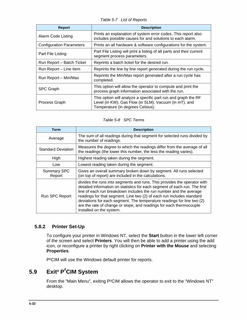
5-32
Table 5-7 List of Reports
Report Description
Alarm Code Listing Prints an explanation of system error codes. This report also includes possible causes for and solutions to each alarm.
Configuration Parameters Prints an all hardware & software configurations for the system.
Part File Listing Part File Listing will print a listing of all parts and their current segment process parameters.
Run Report – Batch Ticket Reprints a batch ticket for the desired run. Run Report – Line Item Reprints the line by line report generated during the run cycle.
Run Report – Min/Max Reprints the Min/Max report generated after a run cycle has completed.
SPC Graph This option will allow the operator to compute and print the process graph information associated with the run.
Process Graph This option will analyze a specific part run and graph the RF Level (in KW), Gas Flow (in SLM), Vacuum (in mT), and Temperature (in degrees Celsius).
Table 5-8 SPC Terms
Term Description
Average The sum of all readings during that segment for selected runs divided by the number of readings.
Standard Deviation Measures the degree to which the readings differ from the average of all the readings (the lower this number, the less the reading varies).
High Highest reading taken during the segment. Low Lowest reading taken during the segment.
Summary SPC Report
Gives an overall summary broken down by segment. All runs selected (on top of report) are included in the calculations.
Run SPC Report
divides the runs into segments and runs. This provides the operator with detailed information on statistics for each segment of each run. The first line of each run breakdown includes the run number and the average readings for that segment. Line two (2) of each run includes standard deviations for each segment. The temperature readings for line two (2) are the rate of change or slope, and readings for each thermocouple installed on the system.
5.8.2 Printer Set-Up
To configure your printer in Windows NT, select the Start button in the lower left corner of the screen and select Printers. You will then be able to add a printer using the add icon, or reconfigure a printer by right clicking on Printer with the Mouse and selecting Properties.
P²CIM will use the Windows default printer for reports.
5.9 Exit² P²CIM System From the “Main Menu”, exiting P²CIM allows the operator to exit to the “Windows NT” desktop.

6-1
6 - Theory of Plasma Desmear Etchback
6.1 Introduction
This section provides background on the development of plasma desmearing technology and describes how the gas plasma desmearing system works. It is not necessary for operators or service personnel to read this section to operate and/or maintain the system. However, an understanding of the reactions of the system parameters (gases, RF energy, temperature, and time) and the manner of controlling these through the operations run is important (in order to get the best results from the system).
6.2 Background
Desmearing multi-layer printed circuits with plasma is the preferred method. Prior to the 1970’s, desmearing was accomplished through a wet process using sulfuric or chromic acid. The process was expensive, time consuming, and required the disposal of hazardous waste chemicals. The wet process involves at least six (6) operations, including an acid bath, a neutralizing bath, and a number of rinses. These operations were replaced by the dry plasma process.
6.3 Process
Plasma desmearing is also a chemical process but is referred to as a dry process (due to there are no liquids involved). RF energy generates highly active metastable free radicals from stable gases. Tetrafluoromethane is mixed with oxygen and fed into a vacuum chamber, where it is excited to a plasma state by RF power. The gas molecules are disassociated and their constituent atoms are ionized by electron impact.
Recombination of electrons, ions, atoms, and molecules result in a great variety of new species in the plasma (more than thirty-six (36) different chemical species have been identified).
These chemical species become the cleaning agents for removing the contaminants in the desmearing process. The main reaction products are water, hydrofluoric acid, and carbon dioxide. Bits of glass bundles and broken pieces of polymer chains remain in the PCB holes. These are referred to as “ash”. The ash is removed with a scrubber or high pressure water rinse. Exposed glass bundles may be removed with a quick dip in an ammonium bifluoride solution.
6

6-2
6.4 Criteria
A plasma desmearing system used in a production environment must meet certain criteria and must produce uniform results. Every hole, in every board, must experience the same level of smear removal and etchback. The failure of a single hole can result in the rejection of an entire board.
The performance of the system must also be repeatable. It is essential to get the same results every time the system is operated with the same parameters. The system must be subject to sensitive and accurate control. The operator must be able to modify the process to achieve desired results.
6.5 Uniformity
The uniformity criteria is achieved when every hole, in every board, is exposed to the same concentration of active species, for the same length of time, and the same temperature. The radicals must be generated and distributed uniformly throughout the chamber. The gas pressure, RF power density, and temperature must be uniform throughout the chamber.
The gases are mixed thoroughly to assure homogeneity and distributed uniformly in the active volume of the chamber. This is accomplished by providing a conic or pyramidal transition area that allows the gas to diffuse evenly into the active volume. As the gases move through the chamber, active species are created in the plasma and are consumed in the reactions.
During operation, the reaction products contaminate the plasma and the constituents of the active species are consumed. The result is a non uniform etch rate along the direction of the gas flow. This is corrected by periodically reversing the direction of the gas flow. The time interval between reversals is short enough to assure uniformity but long enough to minimize wear and tear on valves, solenoids, and other components.
The active species are metastable and must be produced in close proximity to the boards. They are consumed in the reaction and must be regenerated to produce a uniform concentration throughout the active volume of the chamber. The multiple paired electrode system is effective. Closely spaced aluminum panels are attached to power ground to form electrode pairs. A separation of 4in/10cm or 5in/12cm inches between pairs provides adequate regeneration and room to insert boards.
The RF power density is applied uniformly to generate active species in uniform concentration. To avoid the many inherent problems of a high frequency power supply, MPS uses a low frequency supply that operates in the kilohertz range. Resonance conditions are virtually impossible to establish in systems operating at such low frequencies.
Impedance matching is independent of board loading and is accomplished with a transformer. Using the multiple paired electrode design, the energy is coupled to the plasma in the narrow region separating the plates that form electrode pairs. As a result of the greater separation between pairs of electrodes, only a small portion of the energy is coupled into the region occupied by the boards. FCC regulations are favorable for low frequency systems.
6-3
Temperature is a major factor in obtaining uniform reaction. High temperatures are required to operate the system; however, a temperature must be selected that will not damage the boards.
A number of factors contribute to the increase in board temperature. RF energy is dissipated in the plasma and the entire system is heated by energetic electron and ion impact. This process produces the greatest temperatures at the electrodes. The boards are electrically insulated from ground to prevent them from actively participating in the discharge.
The reaction itself is exothermic and contributes to board heating. Most boards are poor thermal conductors and cannot effectively transfer heat to their mechanical supports. Boards are protected from overheating in the multiple paired electrode system by locating them in the secondary discharge region, where the energy density is lower. The plasma is contaminated by the reaction products in the gas phase. These products contribute to the system pressure (and heat load) but diminish the reaction rate.
The vacuum system, with a high pumping speed, decreases the concentration of contaminants in the plasma and promotes high reaction rates at a low system pressure.
6.6 Repeatability
Repeatability is obtained by measuring all process parameters with precision. If the parameters are reproduced the process will produce the same results. The key to repeatability is the history of the boards. The best results are achieved when boards are baked to remove water and volatile solvents immediately before processing.
6.7 Hydrogen based plasma processes.
To ensure controlled release of hydrogen from the process, March Plasma Systems requires that all system exhausts are diluted below the flammability limit of hydrogen. Two controls within the system are required:
1) A nitrogen purge of the process pump and,
2) An automatic system cycle purge between the pre and post-hydrogen process segments.
For purging of the pump a regulated supply of nitrogen (N2) to the pump casing is required. Wet pumps require 2 SLM of nitrogen (N2) and dry pumps require 18 SLM of nitrogen (N2).
(Contact March Plasma Systems for upgrade options if the pump on your system does not have a nitrogen valve installed).

7-1
7 - Preventative Maintenance
7.1 Introduction
The following are periodic maintenance checks to help keep the equipment running at maximum efficiency. For detailed maintenance, refer to the sub-manuals or individual components literature provided.
All maintenance tasks MUST be performed by qualified personnel. Some tasks may be performed by operators purely at the discretion of the customer and this manual makes no attempt to make that determination.
All MPS plasma machines should have an annual factory preventative maintenance check-up by our factory service personnel. Consult your MPS Representative for details.
See Table 7-2 for frequency of maintenance procedures. Maintenance log forms, which can be duplicated, are also included in this manual.
7.2 Pump/Blower Maintenance
WARNING! The correct oil must be used in the pump for safety, as well as, for proper operation. Substituting a hydrocarbon based oil may result in an EXPLOSION!
A clogged oil filter or oil mist device (if so equipped) can also cause a hazard and/or damage to the pump equipment. Change the filter when required per the manufacturer’s instructions.
Never change the filters or oil with equipment running or under vacuum.
Check the level and condition of the oil in the pump and blower daily. Use the inspection portholes on the sides or ends of the pump. If the oil level is 1/4 or less, add oil to the 1/2 mark.
7.2.1 Changing Oil (Systems equipped with wet pumps)
If the machine operates on average 8 hrs daily then change the pump oil every 3 months. If the machine operates multiple shifts change the oil every 520 hours of actual operation (don’t count pump idle time).
7

7-2
Also change the oil if any of the following conditions exist:
1. If the oil is contaminated (appears dark or burned).
2. If the oil is cloudy (with condensate) and will not turn clear when pump is running on gas ballast for two hours.
3. Unable to attain low pressure blank off.
4. When the pump will not be run for an extended period of time (two weeks or more).
Some models are equipped with oil purifiers. If so the filter must be checked bi-monthly and replaced as required. Refer to the pump/blower sub-manuals for correct oil type.
Pumps should run all the time, except when being serviced, to keep oil continuously flowing. This will prevent the oil from becoming too viscous causing difficulty in starting. Some of the older pumps are equipped with electric oil heaters. If the pump is shut down over night the oil heater should be left on to aid in re-starting.
Synthetic oils must be cleaned and recycled. Refer to manufacturer’s recommendations and Material Safety Data sheets.
Oil mist separator: Drain the oil mist separator every two (2) weeks or as required.
Some models are equipped with an MPS fume scrubber unit.
Some systems are equipped with dry pumping systems (no oil in the vacuum path pumps). These units require special attention to the nitrogen and water supplies and other considerations. See appendix “C” for more information.
7.2.2 Hydrogen based plasma processes.
To ensure controlled release of hydrogen from the process, March Plasma Systems requires that all system exhausts are diluted below the flammability limit of hydrogen. Two controls within the system are required:
1) A nitrogen purge of the process pump and,
2) An automatic system cycle purge between the pre and post-hydrogen process segments.
For purging of the pump a regulated supply of nitrogen (N2) to the pump casing is required. Wet pumps require 2 SLM of nitrogen (N2) and dry pumps require 18 SLM of nitrogen (N2).
(Contact March Plasma Systems for upgrade options if the pump on your system does not have a nitrogen valve installed).

7-3
7.3 View Port/Portal Maintenance
The glass used in the chamber view ports is made of heat treated Pyrex® .50”(12.7mm) thick.. When it needs replacing use only a replacement part from MPS.
The O-rings need periodic replacement to prevent leakage or damage to the portal glass and should be inspected or replaced when the door seals are replaced.
7.4 Chamber Maintenance
The chamber should be checked daily for any dirt and foreign material. Completely vacuum out the chamber once a week. Remove the electrodes every six (6) months and completely vacuum out the chamber.
1. Water hoses should be inspected for cracks or leaks monthly. Replace hoses when required ONLY with non-conductive rubber or silicon type hose. Refer to MPS parts dept.
2. Check the electrodes and their screws once a week (to make sure the electrical connections are tight). Check for broken or cracked ceramics (if your model is so equipped) and insulators.
CAUTION! If the electrodes are equipped with ceramic insulators or spacers do not over tighten the screws. They should be hand tight only when electrodes are cold.
3. Clean and inspect the door seal once a week for dirt, nicks, and other defects. Replace the door seal if it’s found to be defective.
Note: Door seals are available from MPS. Keep spares on hand.

7-4
7.5 RF Generator Maintenance 1. Periodically check the back of the unit for dust. Vacuum as necessary.
2. Every six (6) months open the unit and completely vacuum it out.
7.6 Vacuum Exhaust Valves Maintenance
The shaft seal and seal plate o-rings should be replaced every three (3) to six (6) months depending on machine use. Order repair kits from MPS service dept.
7.7 Electrode Maintenance
Electrodes are a wear item. With proper maintenance, the life of the electrodes may be extended to the maximum expected usage. It is recommended that water-cooled electrodes use a dedicated closed loop cooling system. The heat transfer fluid should be single distilled water. This will reduce the amount of sediment deposits that can cause a corrosive reaction with the aluminum.
When plasma is used to process hydrocarbon based materials, a thin coating of residue tends to build up on the electrodes over a period of time. In the early stages of development, this coating does not affect the operation of the equipment or the final product. After continuous operation however, subtle but significant changes can be detected.
To ensure proper operation of your equipment, MPS recommends the electrodes be cleaned every six (6) months or 1,000 hours/operation to remove any contamination. Use the following procedures to remove the contamination without affecting the electrode’s performance.
Note: Contact MPS for additional cleaning methods.

7-5
7.7.1 Standard Cleaning Procedure
7.7.2 Material Requirements
Sodium Hydroxide (See Caution below)
Sulfuric Acid (See Caution below)
City and Distilled Water
CAUTION! These materials are caustic, poisonous and dangerous. Use only after proper safety precautions have been taken and personnel are trained accordingly. Do not use any mechanical means to clean the electrodes, such as wire brushes, sandpaper, or abrasive shot blasting as this will cause leaks and/or shorten their life.
1. Remove the water and power feed connections from the inside of the chamber and remove the power and ground electrodes.
Note: Keep track of each electrode so they can be reinstalled in the same position when cleaning is completed.
2. Cap water inlets and outlets on water cooled models and immerse the disassembled electrodes into a 10% by weight solution of sodium hydroxide at room temperature (70o-80oF). Check the electrodes every two (2) minutes during immersion until the residue is completely removed. The actual cleaning time will depend on the amount of residue that has accumulated on each electrode.
WARNING! The sodium hydroxide solution reacts vigorously with aluminum. Care should be taken to ensure the electrodes remain in the solution for only the amount of time needed to remove the deposits. Potentially explosive hydrogen gas is also produced by the reaction. The working area should therefore be well ventilated.
3. Rinse the electrodes thoroughly in city water for three (3) minutes.
4. Dip the electrodes in a solution of sulfuric acid and water (5% by weight) for one (1) minute (do not allow to dry), go immediately to the next step.
5. Double rinse the electrodes in distilled water for three (3) minutes per rinse.
6. Allow electrodes to stand until completely dry.
7. Reassemble the electrodes in the exact same position (as before), replacing the insulators as required.
8. Reassemble water lines and power connections inside the chamber.
9. Select “Manual Mode” and pump down the chamber.
10. Close both left and right exhaust valves.

7-6
11. Check leak rate and verify that it does not exceed 20Mt/Min.
12. If leaking occurs, seal off the water inlet and outlet fittings. If leak stops, the leak is in the electrode/plumbing assembly.
13. When the leak procedure is complete, attach the water lines to the KF-40 water inlets and outlets.
14. It is recommended to do a “burn-in” procedure after re-installing the electrodes as described below:
A) Oxygen at 100%: Time:10 - minutes RF: 2000 watts
B) Oxygen at 100%: Time:10 - minutes RF: 4000 watts
C) Oxygen at 100%: Time:10 - minutes RF: 6000 watts
D) Oxygen at 100%: Time:10 - minutes RF: 8000 watts
15. The system is ready for standard production.
7.7.3 Replacement Parts
A listing of major replacement parts is includes in the rear section of this manual. When ordering parts please include the machine serial and model numbers. These numbers can be found on the S/N plate located on the front of the main electrical panel.
Machine Serial Number _________________ Model _____________________
If your machine S/N and model information isn’t shown above please find it on the S/N label located on the main electrical panel and fill it in above.
MPS carries thousands of parts in stock ready to ship, however, because many machines are custom made it isn’t possible to provide a complete list of every part available.
All parts used in our machines are available from MPS however certain “uncommon” parts may have to be ordered or manufactured and part prices may change frequently due to suppliers and other costs.
A list of standard “common” parts may be obtained by calling MPS parts or service dept.
Feel free to call MPS parts or service dept. with questions regarding replacement parts, upgrades or current part prices.

7-7
7.8 Gas Cylinder Maintenance
Check the gas cylinder pressure daily. If pressure falls below 100 psi (7bar/kg/cm2), change the cylinder. Material Safety Data Sheets are provided in the back of this manual for common process gases. Add new sheets as required for gases not mentioned in this manual.
7-8
7.9 Maintenance Record Logs
Master forms are provided on the following pages for recording and maintaining your plasma machine maintenance records. Make copies of these forms (as needed).
7.10 Spare Parts Listing
A “recommended replacement parts listing” can be provided for your model plasma machine. This list has been prepared from experience, and is designed to prevent or greatly minimize down time.
Contact MPS Parts Dept. for more information. Please refer to this list and provide the part numbers when ordering replacement or spare parts from MPS.
7.11 Procedure For Emergency Stop Recovery
CAUTION! If the emergency stop is depressed when running in manual or automatic mode of operation with P²CIM the following sequence of steps should be followed to help protect personnel and equipment from injury or damage during restart.
Note: Do not pull the emergency stop button out to its normal operating position until it is called for in the following procedure.
To power down after an emergency stop:
1. After the emergency stop button as been depressed the operator should end the process cycle by pushing the <F10> key (abort for automatic operation) (exit for manual operation) and performing the following steps:
2. Power down the RF power supply.
3. Shut down power to the computer, monitor and battery back-ups.
4. Place main disconnect for the machine in the OFF position.
5. Address the issue for the emergency stop.
To restart the machine:
1. Return emergency stop button to the normal operating position.
2. Turn main disconnect to the on position.
3. Turn on the battery back-up and computer.
4. Turn RF power supply to on position.
5. Start pump and blower.
6. Create a part file for an automatic run. This file should run a dwell mode with 100% nitrogen for approximately five minutes.

7-9
Table 7-1 Machine Maintenance Log
MACHINE MAINTENANCE LOG
MACHINE:
OPERATOR DATE ITEMS TIME PERIOD ADDS/CHANGES
Week One
Gas Leak Check - Oil Levels - Pump Down Daily
Gas Leak Check - Oil Levels - Pump Down Daily
Gas Leak Check - Oil Levels - Pump Down Daily
Gas Leak Check - Oil Levels - Pump Down Daily
Gas Leak Check - Oil Levels - Pump Down Daily
Exhaust Valve Oilers (if installed)
Weekly
Week Two
Gas Leak Check - Oil Levels - Pump Down Daily
Gas Leak Check - Oil Levels - Pump Down Daily
Gas Leak Check - Oil Levels - Pump Down Daily
Gas Leak Check - Oil Levels - Pump Down Daily
Gas Leak Check - Oil Levels - Pump Down
Oil Filter
Exhaust Valve Oilers (if installed)
Daily
Bi-Monthly
Weekly
Week Three
Gas Leak Check - Oil Levels - Pump Down Daily
Gas Leak Check - Oil Levels - Pump Down Daily
Gas Leak Check - Oil Levels - Pump Down Daily
Gas Leak Check - Oil Levels - Pump Down Daily
Gas Leak Check - Oil Levels - Pump Down Daily
Exhaust Valve Oilers (if installed)
Weekly
Week Four Gas Leak Check - Oil Levels - Pump Down Daily
Gas Leak Check - Oil Levels - Pump Down Daily
Gas Leak Check - Oil Levels - Pump Down Daily
Gas Leak Check - Oil Levels - Pump Down Daily
Gas Leak Check - Oil Levels - Pump Down Daily
Exhaust Valve Oilers(if installed)
Fume Scrubbers
Seals
Thermocouples
Weekly
Monthly
Monthly
Monthly

7-10
Table 7-2 Maintenance Schedule
MAINTENANCE SCHEDULE
Item Frequency Maintenance To Perform
Gas Leak Check Daily (A.M.) Check all gas bottles, tubing & fittings for leaks
Oil Level Daily (A.M.) Check oil level in pump and blower. If below halfway mark in sight glass, add appropriate oil to bring level up.
Pump Down Daily (A.M.) Check chamber pressure and record value. If pressure changes by more than 5% from previous day, investigate for leaks.
Exhaust Valve Weekly
Check oil level. If oil is not visible in the sight glass, add appropriate amount to bring level up. If oil needs to be added more than once a week or air bubbles are visible in the sight glass, replace valve seals.
Oil Filters
Bi-Monthly (A.M.) Check Oil filters. If dirty or plugged with oil, replace.
Fume Scrubbers Monthly Check pH. If pH is three (3) or below, neutralize and replace with new solution. See fume scrubber manual for safety procedures.
Seals Monthly Check door and sight glass seals. If worn, cut, or damage affecting vacuum performance, replace.
Thermocouples Monthly Check Teflon sheath on thermocouple. If worn and thermal couple wire is at risk of being exposed, replace.
NOTE: Part racks and carts manufactured by March Plasma Systems have been supplied for the purpose of inserting and restraining product within the chamber/electrode assembly during the plasma process. They have been adjusted specifically for the chamber/electrode assembly for which they were provided. In most cases the racks were designed to keep the product electrically neutral during process. Careful consideration to this aspect of product placement must be taken, when modifications are made to existing part racks, or part racks that were not provided with a particular chamber are inserted into another chamber. Failure to maintain sufficient space between the part racks and RF power or ground will likely result in process failure, and could result in damage to the product, part rack, electrodes, or RF unit.
8-1
8 - Troubleshooting
NOTE: The following procedures in this section are intended for qualified personnel experienced with this type of equipment. Contact MPS service department if additional service is required.
8.1 Leak Checking Chamber
1. Pump the chamber down to base pressure in the manual mode.
2. Burn 100% oxygen for five (5) minutes. Turn off RF and continue pumping down for ten (10) minutes.
3. Seal off the chamber by closing the left and right exhaust valves.
4. Monitor any increase in pressure. It should be less than 20 mT/minute. If not, check all seals to the chamber.
8.2 Leak Checking Gas Line
1. Select manual mode, select even percentage of all gas mass flow controllers.
2. Open left <F1> and right <F2> exhaust valves to allow the chamber to pump down to base pressure.
3. Close the regulator output valves on all gas tanks or gas supply valves.
4. Open left <F3> and right <F4> gas inlets and then again allow chamber to pump down to base pressure.
5. Start gas flow <F6>. Let the system pump until the chamber reaches its base pressure. The base pressure should be same as above. If it is higher then there is a gas line leak. Spray alcohol on all fittings one at a time to find leak. When alcohol enters chamber, then the chamber will spike up in pressure.
8

8-2
8.3 Pump Down Problem
Problem Possible Cause
Chamber will not pump down, exhaust valves don’t open
Door switch, low air supply, E-stop relay, or I/O system failure
Chamber will not pump down to minimum pressure, blower is OFF
Blower (vacuum) switch, vacuum gauge failure, motor starter (contactor), fuse, massive vacuum leak, pump oil level, water leak, gas leak (inlet, purge valve)
Chamber will not pump down to minimum pressure, blower is ON
Vacuum leak, faulty pump or blower, water leak, gas leak (inlet, purge valve)
Pump down alarm happens sometimes, not always
Pump oil level, intermittent leak (door O-ring, N2 purge valve, vacuum break valve, exhaust valve
Blower motor starter is tripping when blower comes on
Blower (vacuum) switch adjustment, faulty vacuum gauge tube, bad heater in motor starter, blower oil level or mechanical problem
8.4 Pressure/Gas Flow Problems
Problem Possible Cause
Pressure alarms all through process. Pressure is “in” and “out” of tolerance many times during the process
Exhaust valve leak, exhaust valve failure, vacuum leak, I/O system, flow controller problem
Gas flow alarm on gas that is not requested at the time Flow controller zero (0) set, I/O system
Gas flow alarm, no gas flow on only one (1) flow controller, all others are okay
Gas supply, loose wire, I/O system faulty flow controller
Gas flow alarm, no gas flow on all flow controllers Loose wire, faulty 15V supply, I/O system inlet valve
Pressure fluctuates when RF comes on (beyond typical rise)
Loose wire, noise to computer through T/C, missing GND, GND loop
8.5 Temperature Problems
Problem Possible Cause
Board Temperature Alarm (critical temperature)
Chamber too hot, thermocouple calibration, improper thermocouple placement, faulty thermocouple, loose or open wire
Temperature goes down when chamber heats up
Thermocouple cable (reverse polarity)
Temperature reading is stuck at zero (0) or another low number
Short circuit, faulty thermocouple, I/O system
Temperature reading is stuck at a very high number
Open circuit, faulty thermocouple, I/O system
Temperature jumps up or jumps around when RF comes on
Loose wire, missing GND, GND loop, thermocouple end may be exposed and ungrounded
Temperature will not reach set point temperature
Thermocouple calibration, thermocouple placement, or faulty thermocouple

8-3
8.6 RF PROBLEMS
Problem Possible Cause
RF will not turn on, front panel lights will not come on Fuse, loose wire, incorrect voltage
RF will not stay on, RF goes off after a short time, RF will not output, front panel lights are on, no flashing lights
Missing control signal, open circuit to electrode, vacuum pressure is too high, incorrect switch settings (local, remote switches)
RF will not output, ARC light is always flashing Faulty generator, faulty inverter module
RF will not output, ARC light flashes when trying to make it output
Electrode short, faulty matching module, bad inverter module, cable short, dirty electrodes
RF will not output, interlock light flashes when trying to make it output
Door switch, 110V (Interlock) relay, loose wire, feed-through cover switch, water pressure switch
RF will not reach set point, set point light starts flashing
Impedance mismatch, chamber pressure is too high, bad inverter module, loose wire, dirty electrode, faulty matching module
8.7 MISCELLANEOUS PROBLEMS
Problem Possible Cause
Computer will not boot up Faulty back-up power supply, incorrect line voltage, faulty computer hardware, back-up power supply connection to power strip on machine.
Computer or Optomux communication problems
Possible Causes: Line voltage fluctuations, loose cabling, bad Opto brain board
Note: This equipment is very sensitive to minor fluctuations in line voltage. A slight variation in incoming voltage will be magnified in the transformers and break communications to the Opto brain boards. Monitor the line voltage to the plasma machine. Reboot the entire system to re-establish communications.
Moisture building up in pump Faulty exhaust line plumbing, cold water running through pump when it’s not running, insufficient N2 Ballast, chamber water leak.
Pump oil level going down Improper suction on exhaust line, massive vacuum leak, faulty oil mist separator, leak in pump or drain.
Excessive CF4 odor Leak in exhaust line or oil mist separator, insufficient N2 purge.
No etch or reduced etch rate Contaminated or low gas supply, faulty flow controller, faulty vacuum gauge, dirty electrodes. Loose ground on electrodes (on systems with isolated RF grounds the connections and the electrodes must not short to the chamber or chassis ground). Possible chamber leak.

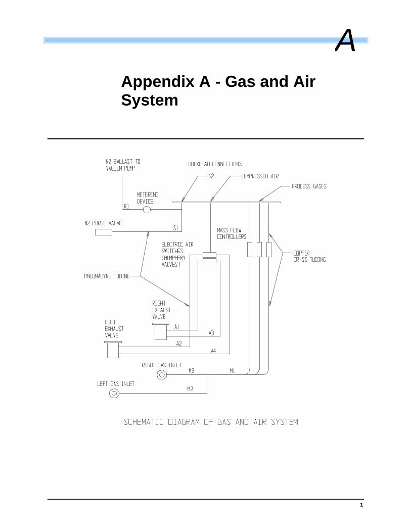
1
Appendix A - Gas and Air System
A
2
Required Reading
Before performing the following tasks, read the listed sections in their entirety.
1. Required reading for all personnel involved:
Section 1 - Introduction
Section 2 - System Overview
2. Before installing an MPS plasma machine:
Section 1 - Introduction
Section 2 - System Overview
Section 3 - Installation
3. Before operating an MPS plasma machine:
Section 1 - Introduction
Section 2 - System Overview
Section 4 - P²CIM2000 W2K Software
4. Before servicing or repairing an MPS plasma machine:
Section 1 - Introduction
Section 2 - System Overview
Section 3 - Installation
Section 7 - Preventative Maintenance
Section 8 - Troubleshooting
5. Before dismantling, storing or transporting an MPS plasma machine:
1.5 De-Commissioning and Disposal
Also read Appendix B in this manual.
6. Before handling gases or materials used in plasma treatment:
1.4 Safety Considerations
3.1.2 Other Considerations
3.3 Utility Connections
3.3.2 Gas and Air Connections
Table 3-2 Some Recommended Compressed Gases with Regulators
Also read the “Material Data Safety Sheets” in the rear of this manual specific to those process gases and materials that you intend to use in plasma treatment.

3

1
Appendix B - Handling and Transportation of an MPS Plasma Machine
MPS plasma machines should only be moved or transported by professional movers or workers skilled in the handling of heavy equipment.
Initial shipment of these machines is done by sub-contracted professional movers and responsibility for safe transportation rests with the moving company. Any problems or damage should be dealt with accordingly.
Once the machine is set-up and leveled no attempt should be made to move or re-align the machine while the manifolds are connected. Serious damage, resulting in leakage, will be done to the connecting manifolds and/or bellows.
If the plasma machine must be moved follow these guidelines and contact your MPS field service representative for assistance.
1. Disconnect electrical power, air, water and gas supplies at the sources. Disconnect the pump unit wires and hoses at the pump end. Mark the ends of the wires before disconnection.
2. Roll up and secure all wires and hoses above the bottom of the machine frame so they will not become tangled or damaged.
3. Mark the location of the manifold pipes on the ends with a black marker then unbolt and remove the bellows and manifolds completely. Immediately cover the openings in the blower/pumps and chamber to avoid introduction of foreign objects.
4. Remove all racks and parts. Block the electrode assemblies inside the chamber. Secure all doors, hoses and loose parts. Move the main machine only with a forklift making sure forks are completely under the frame below the chamber area. Support the machine back and front evenly. Twisting the frame or setting down on an uneven surface will damage the chamber and doors.
5. The pump unit may now be fork lifted from the sides or from the end closest to the pump.
CAUTION! These machines and especially the pump units have a very high center of gravity with most of the weight in the upper portion and therefore must be handled with extreme care to avoid tipping. Do not move up or down steep slopes.
B
2
Appendix C - Dry Pump Information
The pump and blower must have nitrogen and water flow supplied at all times. Flow switches are provided for safety. The Nitrogen supply is to be regulated to 1 bar (14 psi) at the pump in order to provide the appropriate supply pressure to the seal mechanism. The corresponding mass flow of nitrogen is approximately 15-18 SLM. Refer Vacuum Pump Instruction Manual for more detail on the shaft seal.
Dry Pump Start Up and Shut Down:
Start up:
Follow recommended start up procedures as detailed in the Vacuum Pump Instruction Manual. Typical start-up running time is required to warm up the pump is to ensure the vacuum pump is warmed up to running temperature before allowing process gases and vapors to enter the pump. This time will vary with the ambient environment.
Shut down:
Follow recommended shut down procedures as detail in the Vacuum Pump Instruction Manual. The pump requires a 30 minute purge shut down cycle, with shaft seal purge on. This is recommended to allow process gases and vapors to be swept from the vacuum pump and associated vacuum system. If shutdown is going to be a short PM then turn Nitrogen and the water cooling off to the pump while the pump is off to make sure it stays hot.
MPS recommends venting the vacuum system with nitrogen when ever possible. Allowing the vacuum system pump to run for 30 minutes after plasma process will help “dry” the vacuum pump. Ideally, a separate nitrogen purge fitted to the inlet of the vacuum system will assist significantly in sweeping the vacuum system of process gases and vapors prior to shut down. Once complete, the vacuum system contains an inert environment of dry nitrogen.
Summation:
It is recommended that the pump run all of the time. The Nitrogen supply to be regulated to 1 bar (14 psi) at 15-18 SLM to the pump in order to provide the appropriate supply pressure to the seal mechanism. The pump requires a 30 minute purge shut down cycle, with shaft seal purge on. This is recommended to allow process gases and vapors to be swept from the vacuum pump and associated vacuum system.
C
I-1
Index
A Active Species................................................ 2-3 Adding Part File............................................ 5-16 Alarm Tolerance........................................... 5-26 Archive Part File........................................... 5-20 Automatic Mode ............................................. 5-3
function keys .............................................. 5-5
B Backup
machine configuration .............................. 5-27 Blower Delay ................................................ 5-26 Blower Speed................................................. 5-9 Blower Speed Controller .............................. 5-26 Blower Unit ..................................................... 2-2
C Calibration
reset ......................................................... 5-23 Calibration Mode .......................................... 5-21 Calibration Options
calibrate gas............................................. 5-22 calibrate pressure..................................... 5-22 calibrate RF power supply........................ 5-23 calibrate temperature ............................... 5-23
CF4 .................................................................. 5-15 Chamber Door Assembly ............................... 2-1 Chamber Purge.............................................. 5-6 Cleaning Procedure ....................................... 7-4 Compressed Air ............................................. 3-2 Compressed Gases ....................................... 3-7 Computer Startup........................................... 5-1 Conductance Mode ............................... 5-9, 5-14 Configuration Options
security ..................................................... 5-28 Control Mode................................................ 5-15
custom mode............................................ 5-15 dwell mode ............................................... 5-15 power mode.............................................. 5-15 variable mode........................................... 5-15
Cooling Water .............................................. 3-10 Critical Temperature..................................... 5-13 Customer Installation Checklist...................... 3-3
D De-commissioning.......................................... 1-4 Delete Part File ............................................ 5-17 Desmear/Etchback......................................... 1-1 Deviation allowance ..................................... 5-25 Disposal.......................................................... 1-4
E Edit Tracking Fields ......................................5-27 Electrical Connections ............................ 3-5, 7-2 Electrodes ............................................... 2-1, 7-4 Emergencies ...................................................1-3 Emergency Stop
recovery ......................................................7-6 End Process Report........................................5-6
error codes................................................. 5-8 minimum pressure ..................................... 5-8 pump time .................................................. 5-8
Exhaust Connections......................................3-8 Exit P²CIM.....................................................5-30 Expert Operators.............................................5-2
F Final Temperature.........................................5-16 Fixed Flow.......................................................5-9 Fixed Flow Mode...........................................5-13 Floor Space.....................................................3-1 Flow Rate......................................................5-16 Flow Rating (SLM) ........................................5-25 Freon-14 .........................................................3-9
G Gas and Air Connections................................3-7 Gas Cycle Time ............................................5-13 Gas Factor .......................................... 5-22, 5-25 Gas Percentages .................................. 5-9, 5-14 Groups ..........................................................5-29
H Hibernate Mode ............................................5-11
unhibernate ...............................................5-11 Holding............................................................5-6 Hydrogen processes ....................................6.3
I Industrial Nitrogen...........................................3-7 Inlet Valves .....................................................2-3 Installation
materials needed ........................................3-5
K Key Switch ......................................................2-5
L Leak Checking
chamber ......................................................8-1

I-2
gas line ....................................................... 8-1 Login............................................................... 4-3 Lot Complete.................................................. 5-7 Lot number ................................................... 5-28
M Machine Configuration Data
backup...................................................... 5-27 Machine Configuration Wizard............ 5-24, 5-27 Maintenance
chamber ..................................................... 7-2 electrode..................................................... 7-3 gas cylinder ................................................ 7-5 ppump/blower............................................. 7-1 RF Generator ............................................. 7-3 vacuum exhaust valves.............................. 7-3 view port/portal ........................................... 7-2
Maintenance Level ......................................... 5-2 Maintenance Log............................................ 7-6 Manifold Unit .................................................. 2-2 Manual Mode ................................................. 5-8 Mass Flow ...................................................... 5-9 Mass Flow Controllers.................................... 2-2 Mass Flow Mode .......................................... 5-13 Master Level.......................................... 5-2, 5-28 Maximum Pump Time .................................. 5-13 Mixing Gases ................................................. 5-6 Model Number.............................................. 5-25 Modular OPTO Interface System................... 2-3
N N2Purge........................................................ 5-23 Nitrogen.......................................................... 2-2 Number of Segments ................................... 5-14
O Operating Mode .................................... 5-9, 5-13 Operating Pressure ..................................5-9, 5-15 Operator Controls........................................... 2-5 Operator Level ............................................... 5-2
P P2CIM ............................................................. 2-3 P²CIM
exiting ....................................................... 5-23 installation .................................................. 4-2 main menu.................................................. 5-2 starting........................................................ 5-2
Part Number................................................. 5-12 Parts File Parameters .................................. 5-12 Parts Maintenance ....................................... 5-12 Password........................................................ 4-3 Phase Check.................................................. 3-6 Post cycle purges......................................... 5-26 Power Distribution Box................................... 2-2 Power Level ................................................. 5-16
Power Requirements ......................................3-5 Print
print detail .................................................5-26 printer summary ........................................5-26 report print time.........................................5-26
Printer print setup .................................................5-30
Process Control ..............................................5-3 Process Segments........................................5-14 Process Time...................................... 5-16, 5-25 Pump Down ........................5-6, 5-13, 5-16, 5-26 Purge Count..................................................5-26 Purge Inlet Port ...............................................2-1 PWB-Series Floor Plan...................................3-4
R Recommended Compressed Gases.............. 3-9 Repeatability ...................................................6-3 Replacement Parts .........................................7-5 Reports .........................................................5-29 Required Reading.......................................... A-2 Reset Calibration ..........................................5-23 Restore from Archives ..................................5-21 RF Capable Power........................................5-25 RF Cut-off Level............................................5-25 RF power ........................................................6-1 RF Power Supply ............................................2-3 Roto-Trak ........................................................2-5 Run Description ..............................................5-7 Run Numbers................................................5-14
S Safety Considerations.....................................1-3 Serial Number ...............................................5-25 Site Selection ..................................................3-1 Spare Parts .....................................................7-6 Start Cycle ......................................................5-7 System Access Levels
admin level..................................................5-2 maintenance level .......................................5-2 master level.................................................5-2
System Master Keywords ...................5-25, 5-26
T Temperature Deadband................................5-26 Temperature Set ...........................................5-16 Tetrafluoromethane ........................................6-1 Total SLM........................................................5-9 Troubleshooting
gas flow...................................................... 8-2 leaks............................................................8-1 pumpdown ................................................. 8-2 RF .............................................................. 8-3 temperature................................................ 8-2
TRU-Temp ....................................................5-15

I-3
U Uniformity ....................................................... 6-2 Utility Connections ......................................... 3-4
V Vacuum Break..............................2-1, 5-23, 5-26 Vacuum Break Time..................................... 5-25 Vacuum Chamber ................................... 1-3, 2-1
Vacuum Pump ................................................2-2 View Run Results..........................................5-19 View/Edit Parts..............................................5-18
W Warning Labels ...............................................1-2 Warranty ............................................................ ii Warranty Periods ............................................... ii Windows NT..................................................5-30