Embed Size (px)
Citation preview

Master thesis on energy efficiency in rotating equipment L O V E F R I M O D I G l o v e f r i @ k t h . s e 0 7 3 7 - 2 6 8 0 6 5 Course: Master thesis Date: Reviewed by:
09/05-2012 Birger Cederlund, Jakob Kuttenkeuler and Martin Karlsson
Marina system Centre for Naval Architecture

2
SAMMANFATTNING Denna rapport beskriver en studie om hur effektiviteten i en centrifugalpump påverkas av impellerns excentricitet. Geometrin för pumpen är baserad på en centrifugalpump från ERCOFTAC som tidigare har använts för att validera olika fluid dynamiska programvaror genom att jämföra med experimentella resultat. Pumpen är modellerad med hjälp av CFD koden Comsol multiphysics (tm) för att beräkna tryck och hastighetsfält för pumpen i drift. Från tryck och hastighetsfältet beräknas pumpens uteffekt och verkningsgrad. Uteffekt och verkningsgrad jämförs för samma pump med olika mycket statisk excentricitet. För att validera CFD-modellen har resultatet jämförts med tidigare genomförda CFD beräkningar för samma pump samt med experimentella resultat. Jämförelsen visar att resultaten är jämförbara och mycket lika de experimentella resultaten. Studien visar att energiförlusterna ökar med ökad excentricitet på rotorn. Förlusterna vid 10 % excentrisk rotor uppgår till 0.5 % av den producerade energin. Det största bidraget till förlusterna är den införda asymmetrin, som skapar ett ostadigt flöde och ökar krafterna på rotor och lager. Vidare visar studien att interaktionen mellan rotor och statorblad har ett litet inflytande på energiförlusterna. Slutsatsen att rotordynamisk design kan förbättra energieffektiviteten i en process som involverar roterande delar dras. Fortsatt forskning på dynamisk excentricitet, experimentell verifikation av resultatet och mer detaljerade simuleringar föreslås.

3
ABSTRACT This paper reports the findings of the first stage of a study on how the efficiency of a centrifugal pump depends on the eccentricity of the impeller (rotor). The geometry of the pump is based on the ERCOFTAC centrifugal pump that has been used to validate computational fluid dynamics software with laboratory measurements. The pump is modelled using the CFD-code Comsol multi physics (tm) in order to get the pressure and velocity field. From the pressure and velocity field the efficiency and output power for the pump is calculated. The energy efficiency of the same pump with different static eccentricities is then compared, showing the effect of eccentricity To validate the CFD-model the velocity and pressure field for the pump is compared to results from another simulation of the same pump and an experiment. The comparison shows that the results are comparable and shows good agreement with experimental data. It is showed that the energy losses of the pump increase with increased static eccentricity of the impeller. The losses at 10% eccentricity are about 0.5% of the produced energy. The main contribution to the losses is the introduced asymmetry, eccentricity, of the pump, which causes an unsteady flow and also increases the total unbalance force on the rotor. It is further noted that rotor-stator interactions of the impeller and the stator blades have small influence on the energy losses. It is concluded that rotordynamic design can improve the energy efficiency of the process that the rotating equipment is involved in. Further research is suggested on whirling eccentric motion, experimental verification and more detailed simulation models.
INTRODUCTION Common for many rotating machinery is the ability to transfer power from one side of a shaft to the opposite side. The power is usually generated by a turbine or a motor, which is then transferred via a shaft to load units such as generators, process machines such as fiber refiners, fans, pumps, propellers, drills etc. All rotating machinery to different degree suffers from loss of energy. Dissipative mechanisms (damping, friction etc.) convert mechanical energy to thermal energy. In addition to dissipation, there are other forms of energy leakage in rotating machinery transforming the rotating energy to other forms of mechanical energy, which results in vibration of the rotor system, the supporting structure and interactions with electromagnetic fields and surrounding fluids. Since energy is expensive an important engineering challenge is to reduce the energy leakage, both in form of dissipation and vibrations. In addition, vibrations lead to other problems in the mechanical equipment such as stress, fatigue, friction, wear out, impacts, noise and damage. Dynamics of rotating machinery i.e. rotordynamics, is normally considered as a separate area within dynamics [1, 2]. The two major differences from structural dynamics are that in rotating machinery, the Eigen frequencies depend on the whirling speed due to the gyroscopic effect and the direction of the vibrations is important (forward and backward whirl). In addition, interactions with bearings, seals, electromagnetic equipment and process equipment must be considered when modeling rotordynamic systems. These interactions are often multiphysical e.g. fluid-rotor, rotor-structure or electromechanical interactions. There exists a lot of research on such interactions where the early research was focused on analytical models and empirical testing [3]. Today, state-of-the-art finite element and finite volume computer software’s are used to calculate rotordynamical coefficients for the multiphysical interactions [4]. Muszynska [5] stated that one reason to decrease the vibrations in rotating system is to reduce energy losses due to vibrations. Losses in bearings are straight forward calculate and monitor. However there are no published reports on how vibration affects the process equipment (i.e. turbine, compressor, fan or pump) or the electric machine. Hence, the overall aim for an ongoing project at ÅF is to facilitate decrease of energy losses in rotating process machineries through
4
understanding of how vibrations in rotating machinery affects the flow in process equipment as well as the magnetic field in electrical machines. This study will focus on the flow in a centrifugal pump and aims to determine how, and to what extent, static eccentricity affect the flow and the efficiency of the machine, the research in this paper is guided by the question: How is the efficiency in a centrifugal pump coupled to static eccentricity of the impeller?
2. METHOD In order to understand how the energy efficiency of the ERCOFTAC centrifugal pump, described in [6], is affected by static eccentricity the power output and efficiency factor for the pump is calculated for two cases. Case one is the pump with a centred impeller and case two is the same pump but with 5 different static eccentricities, 5, 10, 15, 20, 25 % of the clearance between the impeller and stator blades. A 2D model of the pump is built up in Comsol multiphysics (tm) where the incompressible unsteady Reynolds averaged Navier stokes equations, URANS, are solved in order to obtain the pressure and velocity field for the centrifugal pump. The pressure and velocity field is then used to calculate the output power for each case of the pump. The power output for each case is then compared, showing how the efficiency is affected by the eccentricity.
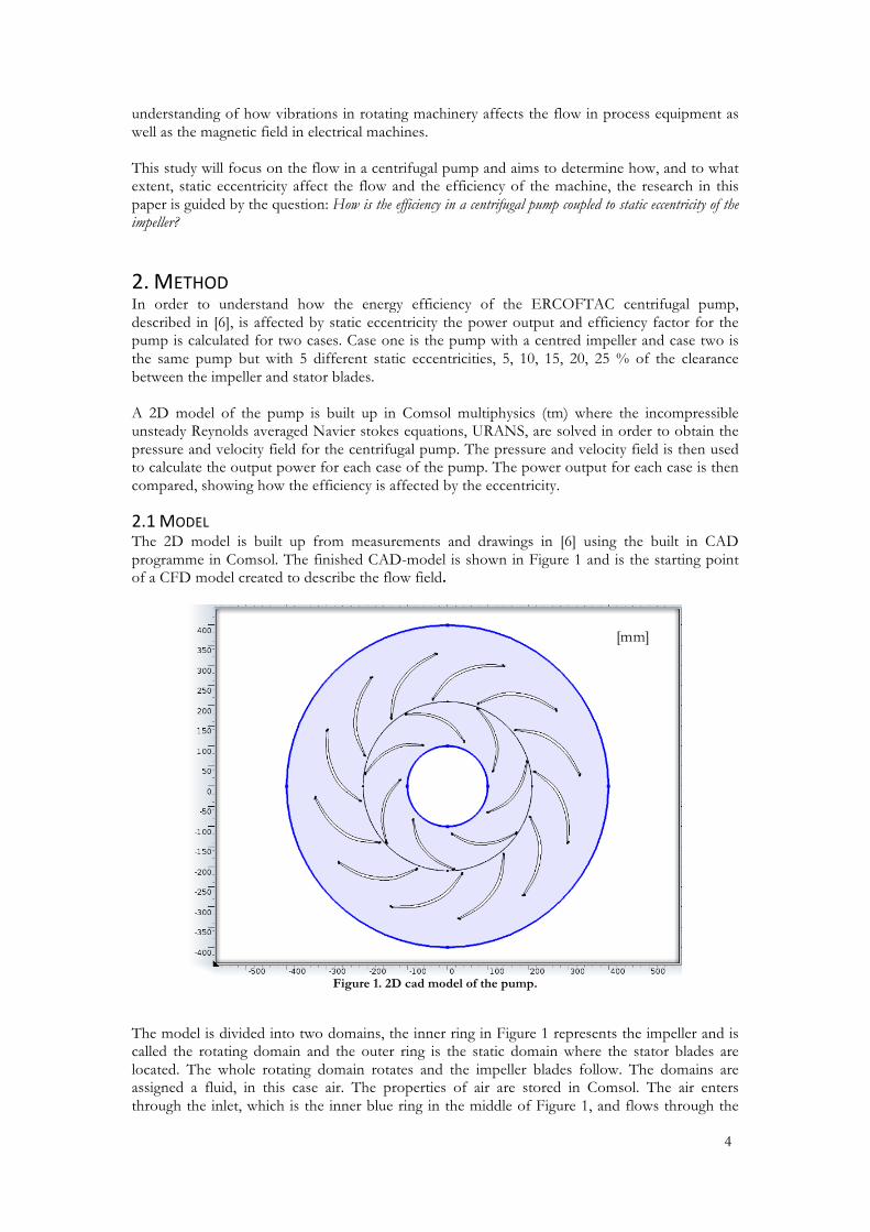
2.1 MODEL The 2D model is built up from measurements and drawings in [6] using the built in CAD programme in Comsol. The finished CAD-model is shown in Figure 1 and is the starting point of a CFD model created to describe the flow field.
Figure 1. 2D cad model of the pump.
The model is divided into two domains, the inner ring in Figure 1 represents the impeller and is called the rotating domain and the outer ring is the static domain where the stator blades are located. The whole rotating domain rotates and the impeller blades follow. The domains are assigned a fluid, in this case air. The properties of air are stored in Comsol. The air enters through the inlet, which is the inner blue ring in the middle of Figure 1, and flows through the
[mm]
5
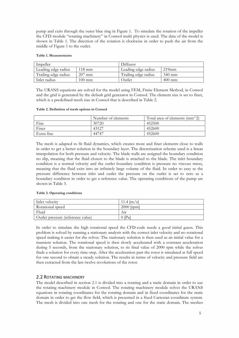
pump and exits through the outer blue ring in Figure 1. To simulate the rotation of the impeller the CFD module “rotating machinery” in Comsol multi physics is used. The data of the model is shown in Table 1. The direction of the rotation is clockwise in order to push the air from the middle of Figure 1 to the outlet. Table 1. Measurements
Impeller Diffusor Leading edge radius 118 mm Leading edge radius 219mm Trailing edge radius 207 mm Trailing edge radius 340 mm Inlet radius 100 mm Outlet 400 mm The URANS equations are solved for the model using FEM, Finite Element Method, in Comsol and the grid is generated by the default grid generator in Comsol. The element size is set to finer, which is a predefined mesh size in Comsol that is described in Table 2. Table 2. Definition of mesh options in Comsol
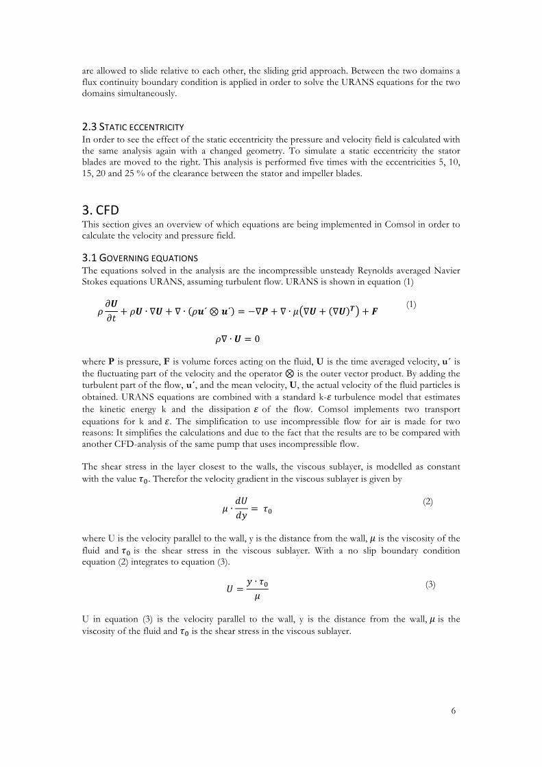
Number of elements Total area of elements (mm^2) Fine 30720 452500 Finer 43127 452600 Extra fine 44747 452600 The mesh is adapted to fit fluid dynamics, which creates more and finer elements close to walls in order to get a better solution in the boundary layer. The discretization scheme used is a linear interpolation for both pressure and velocity. The blade walls are assigned the boundary condition no slip, meaning that the fluid closest to the blade is attached to the blade. The inlet boundary condition is a normal velocity and the outlet boundary condition is pressure no viscous stress, meaning that the fluid exits into an infinitely large volume of the fluid. In order to easy se the pressure difference between inlet and outlet the pressure on the outlet is set to zero as a boundary condition in order to get a reference value. The operating conditions of the pump are shown in Table 3. Table 3. Operating conditions
Inlet velocity 11.4 [m/s] Rotational speed 2000 [rpm] Fluid Air Outlet pressure (reference value) 0 [Pa] In order to simulate the high rotational speed the CFD-code needs a good initial guess. This problem is solved by running a stationary analysis with the correct inlet velocity and no rotational speed making it easier for the solver. The stationary solution is then used as an initial value for a transient solution. The rotational speed is then slowly accelerated with a constant acceleration during 5 seconds, from the stationary solution, to its final value of 2000 rpm while the solver finds a solution for every time-step. After the acceleration part the rotor is simulated at full speed for one second to obtain a steady solution. The results in terms of velocity and pressure field are then extracted from the last twelve revolutions of the rotor.
2.2 ROTATING MACHINERY The model described in section 2.1 is divided into a rotating and a static domain in order to use the rotating machinery module in Comsol. The rotating machinery module solves the URANS equations in rotating coordinates for the rotating domain and in fixed coordinates for the static domain in order to get the flow field, which is presented in a fixed Cartesian coordinate system. The mesh is divided into one mesh for the rotating and one for the static domain. The meshes
6
are allowed to slide relative to each other, the sliding grid approach. Between the two domains a flux continuity boundary condition is applied in order to solve the URANS equations for the two domains simultaneously.
2.3 STATIC ECCENTRICITY In order to see the effect of the static eccentricity the pressure and velocity field is calculated with the same analysis again with a changed geometry. To simulate a static eccentricity the stator blades are moved to the right. This analysis is performed five times with the eccentricities 5, 10, 15, 20 and 25 % of the clearance between the stator and impeller blades.
3. CFD This section gives an overview of which equations are being implemented in Comsol in order to calculate the velocity and pressure field.
3.1 GOVERNING EQUATIONS The equations solved in the analysis are the incompressible unsteady Reynolds averaged Navier Stokes equations URANS, assuming turbulent flow. URANS is shown in equation (1)
𝜌𝜕𝑼𝜕𝑡
+ 𝜌𝑼 ∙ ∇𝑼 + ∇ ∙ 𝜌𝒖´⊗ 𝒖´ = −∇𝑷 + ∇ ∙ 𝜇 ∇𝑼 + ∇𝑼 𝑻 + 𝑭
(1)
𝜌∇ ∙ 𝑼 = 0
where P is pressure, F is volume forces acting on the fluid, U is the time averaged velocity, u´ is the fluctuating part of the velocity and the operator ⊗ is the outer vector product. By adding the turbulent part of the flow, u´, and the mean velocity, U, the actual velocity of the fluid particles is obtained. URANS equations are combined with a standard k-𝜀 turbulence model that estimates the kinetic energy k and the dissipation 𝜀 of the flow. Comsol implements two transport equations for k and 𝜀. The simplification to use incompressible flow for air is made for two reasons: It simplifies the calculations and due to the fact that the results are to be compared with another CFD-analysis of the same pump that uses incompressible flow. The shear stress in the layer closest to the walls, the viscous sublayer, is modelled as constant with the value 𝜏!. Therefor the velocity gradient in the viscous sublayer is given by
𝜇 ∙𝑑𝑈𝑑𝑦
= 𝜏! (2)
where U is the velocity parallel to the wall, y is the distance from the wall, 𝜇 is the viscosity of the fluid and 𝜏! is the shear stress in the viscous sublayer. With a no slip boundary condition equation (2) integrates to equation (3).
𝑈 =𝑦 ∙ 𝜏!𝜇
(3)
U in equation (3) is the velocity parallel to the wall, y is the distance from the wall, 𝜇 is the viscosity of the fluid and 𝜏! is the shear stress in the viscous sublayer.
7
4 POWER AND EFFICIENCY When the pressure and velocity field is known the power output performed by the impeller can be calculated. The actual power from the impeller, the energy put into the system via a shaft per time, can be calculated with equation (4).
𝑀 ∙ 𝜔 (4)
In equation (4) 𝑀 is the moment applied on the impeller and 𝜔 is the rotational speed. By integrating the pressure times the area along the impeller blades the force acting on the blades is obtained. When the force is known the moment on the impeller can be calculated. The useful work performed by the impeller can be derived using the first law of thermodynamics for an open system with one inlet and one outlet described in [7]. Work is performed on the surrounding fluid at the inlet and at the outlet stated in [7]. By adding the work performed at the inlet and at the outlet the total work from the system is obtained. If the process is considered to be adiabatic and the medium is incompressible, the useful work from the impeller can be calculated with equation (5) as the total work performed by the system i.e. the impeller.
𝑊!"#$%%$& = Δ𝑝 ∙ 𝑉!"#$% ∙ 𝐴!"#$%
(5)
In equation (5) 𝑝 is the pressure, 𝑊!"#$%%$& is the work from the impeller, 𝑉!"#$% and 𝐴!"#$% is the velocity and area at the inlet. When the useful work and the actual work are known equation (4) and (5) can be combined to calculate the efficiency factor according to equation (6).
𝜂 = Δ𝑝 ∙ 𝑉!"#$% ∙ 𝐴!"#$%
𝑀 ∙ 𝜔
(6)
Equation (6) is based on the fact work is performed by the fluid at the inlet and the outlet of the volume which is the total “good” work performed by the impeller. The efficiency factor for each rotor case is calculated from RMS-values of the pressure difference, velocities and moment based on twelve revolutions in steady state.
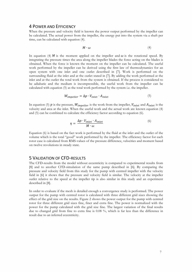
5 VALIDATION OF CFD‐RESULTS The CFD-results from the model without eccentricity is compared to experimental results from [8] and to another CFD-simulation of the same pump described in [6]. By comparing the pressure and velocity field from this study for the pump with centred impeller with the velocity field in [6] it shows that the pressure and velocity field is similar. The velocity at the impeller outlet relative to the speed at the impeller tip is also similar in this study and an experiment described in [8]. In order to evaluate if the mesh is detailed enough a convergence study is performed. The power output for the pump with centred rotor is calculated with three different grid sizes showing the effect of the grid size on the results. Figure 2 shows the power output for the pump with centred rotor for three different grid sizes fine, finer and extra fine. The power is normalized with the power for the pump calculated with the grid size fine. The largest variation of the final results due to changed grid from fine to extra fine is 0.08 %, which is far less than the difference in result due to an inferred eccentricity.
8
Figure 2.Normalized power output for the pump with centred impeller as a function of grid size.
The definition of fine, finer and extra fine in Figure 2 is described in Table 2.
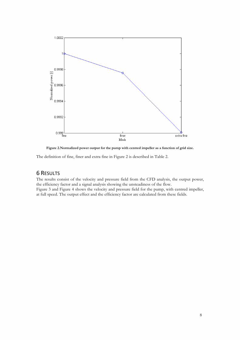
6 RESULTS The results consist of the velocity and pressure field from the CFD analysis, the output power, the efficiency factor and a signal analysis showing the unsteadiness of the flow. Figure 3 and Figure 4 shows the velocity and pressure field for the pump, with centred impeller, at full speed. The output effect and the efficiency factor are calculated from these fields.
9
Figure 3. Velocity field of the pump with centred impeller showing the velocity magnitude.
The colours in Figure 3 represents the absolute value of the velocity and the black arrows shows the direction of the fluid.
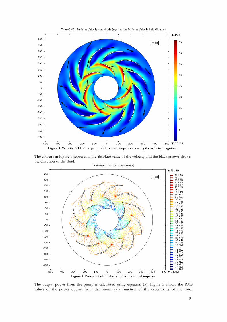
Figure 4. Pressure field of the pump with centred impeller.
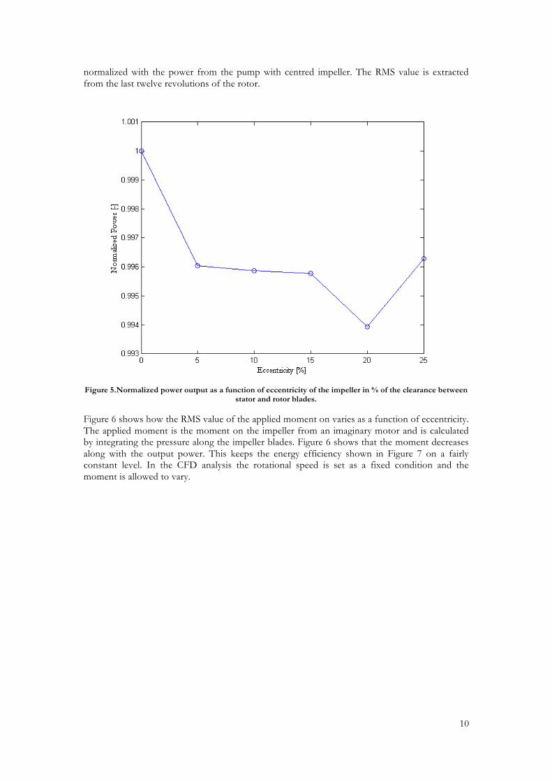
The output power from the pump is calculated using equation (5). Figure 5 shows the RMS values of the power output from the pump as a function of the eccentricity of the rotor
[mm]
[mm]
10
normalized with the power from the pump with centred impeller. The RMS value is extracted from the last twelve revolutions of the rotor.
Figure 5.Normalized power output as a function of eccentricity of the impeller in % of the clearance between
stator and rotor blades.
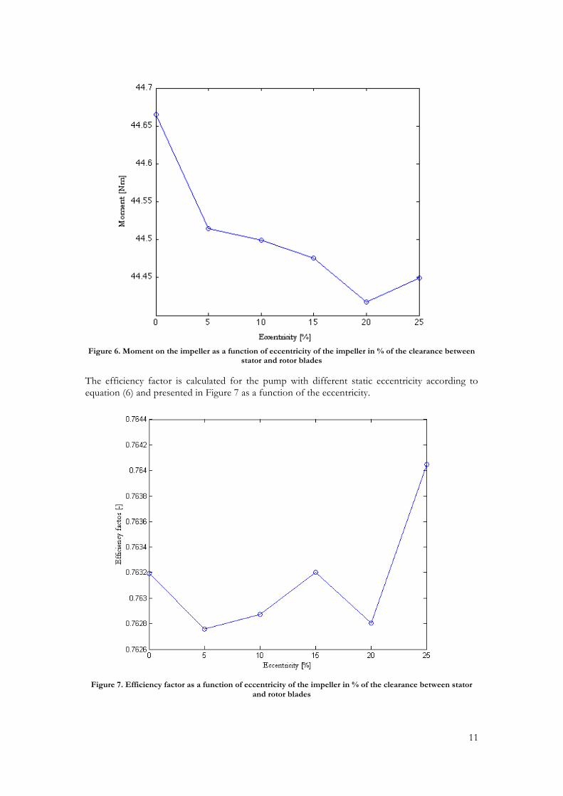
Figure 6 shows how the RMS value of the applied moment on varies as a function of eccentricity. The applied moment is the moment on the impeller from an imaginary motor and is calculated by integrating the pressure along the impeller blades. Figure 6 shows that the moment decreases along with the output power. This keeps the energy efficiency shown in Figure 7 on a fairly constant level. In the CFD analysis the rotational speed is set as a fixed condition and the moment is allowed to vary.
11
Figure 6. Moment on the impeller as a function of eccentricity of the impeller in % of the clearance between
stator and rotor blades
The efficiency factor is calculated for the pump with different static eccentricity according to equation (6) and presented in Figure 7 as a function of the eccentricity.
Figure 7. Efficiency factor as a function of eccentricity of the impeller in % of the clearance between stator
and rotor blades
12
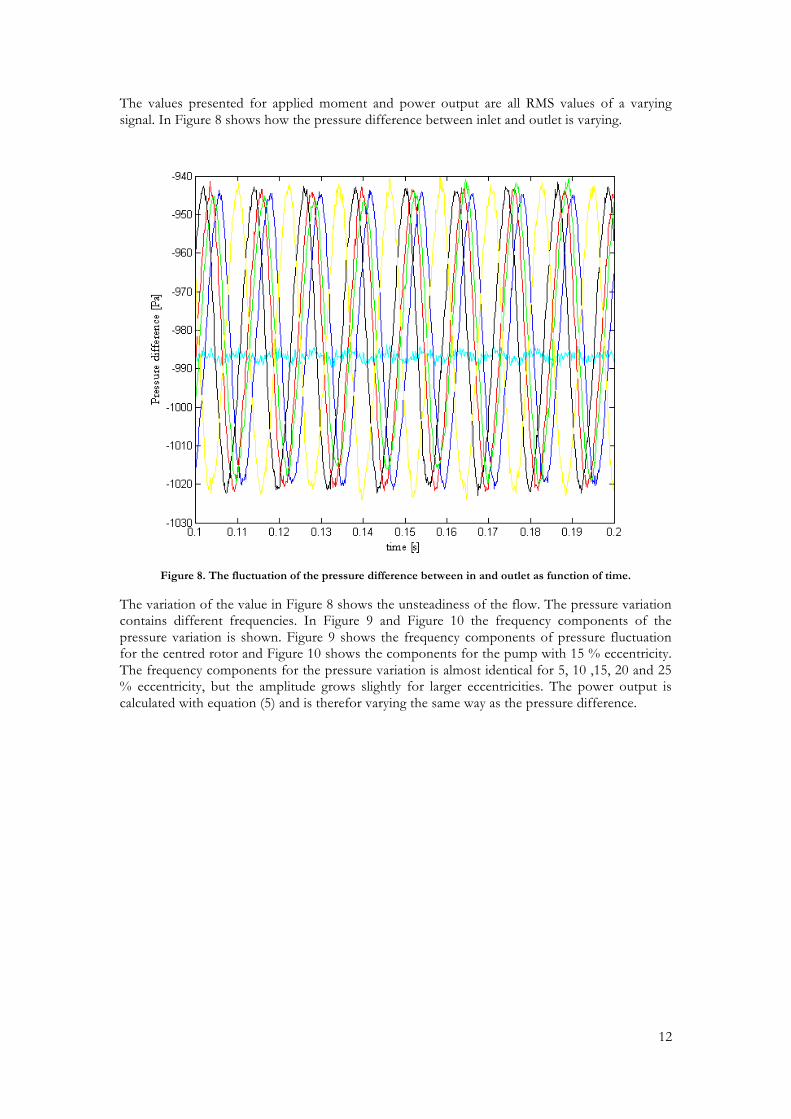
The values presented for applied moment and power output are all RMS values of a varying signal. In Figure 8 shows how the pressure difference between inlet and outlet is varying.
Figure 8. The fluctuation of the pressure difference between in and outlet as function of time.
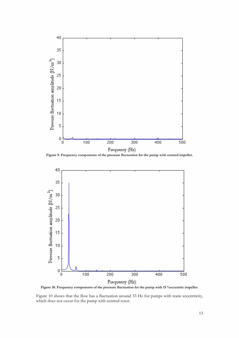
The variation of the value in Figure 8 shows the unsteadiness of the flow. The pressure variation contains different frequencies. In Figure 9 and Figure 10 the frequency components of the pressure variation is shown. Figure 9 shows the frequency components of pressure fluctuation for the centred rotor and Figure 10 shows the components for the pump with 15 % eccentricity. The frequency components for the pressure variation is almost identical for 5, 10 ,15, 20 and 25 % eccentricity, but the amplitude grows slightly for larger eccentricities. The power output is calculated with equation (5) and is therefor varying the same way as the pressure difference.
13
Figure 9. Frequency components of the pressure fluctuation for the pump with centred impeller.
Figure 10. Frequency components of the pressure fluctuation for the pump with 15 %eccentric impeller.
Figure 10 shows that the flow has a fluctuation around 33 Hz for pumps with static eccentricity, which does not occur for the pump with centred rotor.
14
7 DISCUSSION There is always an error in a CFD analysis depending on the accepted error, residual, and errors due to a to rough grid. The convergence study shown in Figure 2 shows that the change in the result due to the grid is less than 1‰, which is small compared to the differences in output power due to the static eccentricity. More accurate methods to evaluate the error due to the grid exist, but a rough estimation of the error is considered to be sufficient in this study. The fact that the results from this study shows good agreement with other studies makes it reasonable to believe that the results are correct. Systematic errors such as geometry differences from the original pump do not affect the result since it is the comparison between the different eccentricities that is important. This study settles that a static eccentricity could decrease the output effect of a centrifugal pump with about 0.5 % and that even a small eccentricity can cause an unsteady flow that leads to a decrease of the effect. This implies that the design of the rotor can improve the efficiency of a rotating machinery. By knowing how much a static eccentricity affects the output power one can decide whether it is worth fixing or not. This could be a grate benefit to power plants where even a small increase in effect is worth a lot. The fluctuation of the flow is dominated by the frequency 33 Hz, which is presented in Figure 10. This is the same frequency as the revolutions per second, which leads to the conclusion that it is asymmetry of the pump and not the blade interactions that causes most energy leakage. This asymmetry will also contribute to the total unbalance of the rotor. The CFD analysis has the rotational speed as a fixed condition. This fact combined with the result from Figure 5 shows that the power output decreases with increased eccentricity. However in many real applications it is the moment and not the rotational speed that is constant. Therefor it would be interesting to preform a study with constant moment instead of constant speed. The moment applied by the impeller also decrease as a function of the eccentricity as seen in Figure 6. The effect of this is that the efficiency factor, shown in Figure 7, does not change much when the eccentricity is inferred into this model. This is another reason to preform the simulation with a constant applied moment instead of constant speed and se how the efficiency factor varies. In this study the air is modelled as incompressible in order to simplify the calculations and to get a better comparison to the study in [6] that modelled the air as incompressible. This simplification will generate an error that is assumed to be small and systematic. Further research is suggested on dynamic eccentricity and whirling along with experimental confirmation of the results. This study is a pre-study with the aim to investigate if, and how, a static eccentricity affects the energy efficiency in order to see if there is any use in further studies. From the results presented in this paper it is concluded that there is a clear connection between eccentricity and unsteady flow causing a less efficient pump. Further research is therefore recommended.
8 REFERENCES [1] Childs, D., Turbomachinery Rotordynamics – Phenomena, Modeling, & Analysis, New York 1993 [2] Yamamoto, T., Ishida, Y., Linear and Non-linear Rotordynamics. Wiley-Intersciences, New-York, 2003 [3] Black, H., Effects of Fluid-Filled Clearance Spaces on Centrifugal Pump and Submerged Motor Vibrations, In the Proceedings of the Eight Turbomachinery Symposium, Texas A&M University, pp. 29-38 [4] Karlsson, M., Modelling and analysis of multiphysical interactions in hydropower rotor systems, Doctoral Thesis, Luleå University of Technology, Luleå 2008 [5] Muszynska, A, Rotordynamics, Taylor & Francis Group,Boca Raton, 2005 [6] O Petite, M Page, M Beaudoin, H Nilsson. The ERCOFTAC centrifugal pump OpenFOAM case-study

15
[7] T Burden. Thermo dynamics and compressible flow, Stockholm, KTH 2009 [8] M. Ubaldi. An experimental investigation of stator induced un steadiness on a centrifugal impeller
16
APPENDIX 1. PERSONAL REFLECTION
PERSONAL REFLECTION ON PROGRAM-LEVEL LEARNING OBJECTIVES INSTRUCTIONS: Please consider the list of intended learning outcomes for the master program (and specialization in your civilingenjörsprogram) and reflect on your status in relation to them. Your task is to
• Estimate your proficiency using the numbered levels according to the Feisel-Schmitz taxonomy (at the yyy inside the table). See description below the table.
• Write a few lines on each outcome to indicate your status (at the Xxx inside the table). Try to indicate what learning activities you have been engaged in that made you climb the taxonomy.
Program Learning Objectives The main objective of this program is to educate skilled engineers for industry and research institutions. The field is broad and multi-disciplinary with strong emphasis on systems engineering. A naval architect needs a variety of skills, knowledge and abilities to contribute to the complete processes of design, implementation and operation of marine vessels/systems which can be very large and complex systems, as well as deep understanding in some subjects. The program offers specialization within the predefined profiles Lightweight Structures, Fluid Mechanics, Sound & Vibration, Management, and Sustainable Development, as well as the possibility to individually tailor the profile. The subject hence is attractive also for students who are not devoted to work in the maritime sector and relevant for careers also in other fields.
Knowledge and understanding: A Master of Science in Naval Architecture shall demonstrate:
1
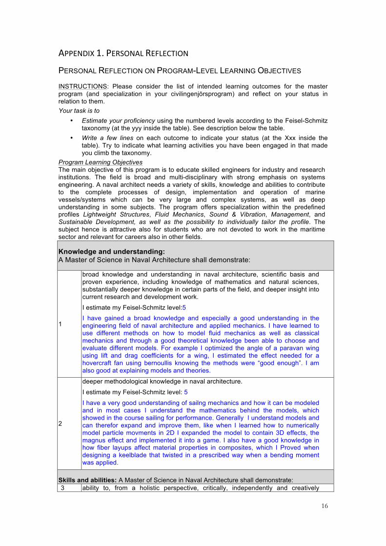
broad knowledge and understanding in naval architecture, scientific basis and proven experience, including knowledge of mathematics and natural sciences, substantially deeper knowledge in certain parts of the field, and deeper insight into current research and development work.
I estimate my Feisel-Schmitz level:5 I have gained a broad knowledge and especially a good understanding in the engineering field of naval architecture and applied mechanics. I have learned to use different methods on how to model fluid mechanics as well as classical mechanics and through a good theoretical knowledge been able to choose and evaluate different models. For example I optimized the angle of a paravan wing using lift and drag coefficients for a wing, I estimated the effect needed for a hovercraft fan using bernoullis knowing the methods were “good enough”. I am also good at explaining models and theories.
2
deeper methodological knowledge in naval architecture.
I estimate my Feisel-Schmitz level: 5
I have a very good understanding of sailng mechanics and how it can be modeled and in most cases I understand the mathematics behind the models, which showed in the course sailing for performance. Generally I understand models and can therefor expand and improve them, like when I learned how to numerically model particle movments in 2D I expanded the model to contain 3D effects, the magnus effect and implemented it into a game. I also have a good knowledge in how fiber layups affect material properties in composites, which I Proved when designing a keelblade that twisted in a prescribed way when a bending moment was applied.
Skills and abilities: A Master of Science in Naval Architecture shall demonstrate: 3 ability to, from a holistic perspective, critically, independently and creatively
17
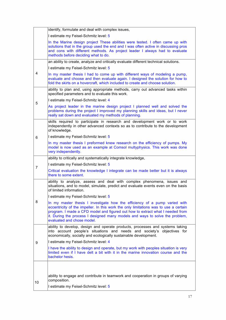
identify, formulate and deal with complex issues,
I estimate my Feisel-Schmitz level: 5
In the Marine design project These abilities were tested. I often came up with solutions that in the group used the end and I was often active in discussing pros and cons with different methods. As project leader I always had to evaluate methods before deciding what to do.
4
an ability to create, analyze and critically evaluate different technical solutions.
I estimate my Feisel-Schmitz level: 5
In my master thesis I had to come up with different ways of modeling a pump, evaluate and choose and then evaluate again. I designed the solution for how to fold the skirts on a hovercraft, which included to create and choose solution.
5
ability to plan and, using appropriate methods, carry out advanced tasks within specified parameters and to evaluate this work.
I estimate my Feisel-Schmitz level: 4
As project leader in the marine design project I planned well and solved the problems during the project I improved my planning skills and ideas, but I never really sat down and evaluated my methods of planning.
6
skills required to participate in research and development work or to work independently in other advanced contexts so as to contribute to the development of knowledge.
I estimate my Feisel-Schmitz level: 5
In my master thesis I preformed knew research on the efficiency of pumps. My model is now used as an example at Comsol multyphysics. This work was done very independently.
7
ability to critically and systematically integrate knowledge,
I estimate my Feisel-Schmitz level: 5
Critical evaluation the knowledge I integrate can be made better but it is always there to some extent.
8
ability to analyze, assess and deal with complex phenomena, issues and situations, and to model, simulate, predict and evaluate events even on the basis of limited information.
I estimate my Feisel-Schmitz level: 5
In my master thesis I investigate how the efficiency of a pump varied with eccentricity of the impeller. In this work the only limitations was to use a certain program. I made a CFD model and figured out how to extract what I needed from it. During the process I designed many models and ways to solve the problem, evaluated and chose model.
9
ability to develop, design and operate products, processes and systems taking into account people’s situations and needs and society’s objectives for economically, socially and ecologically sustainable development.
I estimate my Feisel-Schmitz level: 4
I have the ability to design and operate, but my work with peoples situation is very limited even if I have delt a bit with it in the marine innovation course and the bachelor hesis.
10
ability to engage and contribute in teamwork and cooperation in groups of varying composition. I estimate my Feisel-Schmitz level: 5
18
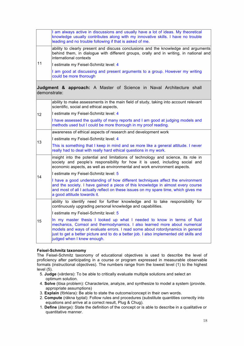
I am always active in discussions and usually have a lot of ideas. My theoretical knowledge usually contributes along with my innovative skills. I have no trouble leading and no trouble following if that is asked of me.
11
ability to clearly present and discuss conclusions and the knowledge and arguments behind them, in dialogue with different groups, orally and in writing, in national and international contexts I estimate my Feisel-Schmitz level: 4
I am good at discussing and present arguments to a group. However my writing could be more thorough
Judgment & approach: A Master of Science in Naval Architecture shall demonstrate:
12
ability to make assessments in the main field of study, taking into account relevant scientific, social and ethical aspects, I estimate my Feisel-Schmitz level: 4
I have assessed the quality of many reports and I am good at judging models and methods used but I could be more thorough in my proof reading.
13
awareness of ethical aspects of research and development work
I estimate my Feisel-Schmitz level: 4 This is something that I keep in mind and se more like a general attitude. I never really had to deal with really hard ethical questions in my work.
14
insight into the potential and limitations of technology and science, its role in society and people’s responsibility for how it is used, including social and economic aspects, as well as environmental and work environment aspects.
I estimate my Feisel-Schmitz level: 5 I have a good understanding of how different techniques affect the environment and the society. I have gained a piece of this knowledge in almost every course and most of all I actually reflect on these issues on my spare time, which gives me a good attitude towards it.
15
ability to identify need for further knowledge and to take responsibility for continuously upgrading personal knowledge and capabilities.
I estimate my Feisel-Schmitz level: 5 In my master thesis I looked up what I needed to know in terms of fluid mechanics, Comsol and thermodynamics. I also learned more about numerical models and ways of evaluate errors. I read some about rotordynamics in general just to get a better picture and to do a better job. I also implemented old skills and judged when I knew enough.
Feisel-Schmitz taxonomy The Feisel-Schmitz taxonomy of educational objectives is used to describe the level of proficiency after participating in a course or program expressed in measurable observable formats (instructional objectives). The numbers range from the lowest level (1) to the highest level (5).
5. Judge (värdera): To be able to critically evaluate multiple solutions and select an optimum solution.
4. Solve (lösa problem): Characterize, analyze, and synthesize to model a system (provide. appropriate assumptions)
3. Explain (förklara): Be able to state the outcome/concept in their own words. 2. Compute (räkna typtal): Follow rules and procedures (substitute quantities correctly into
equations and arrive at a correct result, Plug & Chug). 1. Define (återge): State the definition of the concept or is able to describe in a qualitative or
quantitative manner.

19