Embed Size (px)
Citation preview

Copyrig
ht
©, W
eber
Ma
rkin
g S
yste
ms G
mb
H
Translation of the original operating manual
Markoprint Integra Quadro
Part number of documentation 40065945
(GB) English
Version: 04.07.2018
Weber Marking Systems GmbH
Maarweg 33
D-53619 Rheinbreitbach
E-Mail: [email protected]
http://www.webermarking.de

Blank page

Contents 40065945 Markoprint Integra Quadro
Page 3 of 118 GB
Table of contents
General ........................................................................................................................... 5
Explanation of Technical Terms ........................................................................................ 8
Safety Regulations ...................................................................................................... 11
Behavior in Case of an Emergency ................................................................................. 11 Explanation of Danger Degrees....................................................................................... 11 Special hazards ............................................................................................................... 14
Technical data .............................................................................................................. 19
Performance data ............................................................................................................ 21
Transport, Packaging and Storage ............................................................................ 23
Transport ......................................................................................................................... 23 Packaging ....................................................................................................................... 25 Storage control system .................................................................................................... 26
Assembly and function ............................................................................................... 27
Brief description .............................................................................................................. 27 Controller ........................................................................................................................ 27 System versions .............................................................................................................. 28 Overview Markoprint Integra Quadro Steuergerät ........................................................... 29 Nameplate ....................................................................................................................... 30
Installation and initial operation ................................................................................. 31 Installation .................................................................................................................................... 33 Requirements to the Site of Installation ....................................................................................... 33 Placing the control system ........................................................................................................... 33
Positioning the Control System........................................................................................ 34 Installation of the print heads ........................................................................................... 35 Connecting the control system ........................................................................................ 36
Connecting of the Print heads ...................................................................................................... 37 Connecting the optional Shaft Encoder ....................................................................................... 38 Connecting the optional Product Sensor ..................................................................................... 38
Configuration of the print technology ............................................................................... 41
Operation ...................................................................................................................... 43
Switch on ........................................................................................................................ 43 Switch off ........................................................................................................................ 43 Menu structure ................................................................................................................ 48 Print start ......................................................................................................................... 53 Variable input .................................................................................................................. 53 Input counter start value .................................................................................................. 54 Print start delay ............................................................................................................... 55 To set the encoder resolution .......................................................................................... 59 To set the Zoom .............................................................................................................. 61 Print direction .................................................................................................................. 62 Upside down ................................................................................................................... 64 Head adjustment ............................................................................................................. 65 USB-Stick ........................................................................................................................ 67 Date / Time ..................................................................................................................... 68 Select sensor .................................................................................................................. 69 IP-address and NET-mask .............................................................................................. 70 Gate-Way and MAC address ........................................................................................... 71

Contents 40065945 Markoprint Integra Quadro
Page 4 of 118 GB
Set language at the system ............................................................................................. 72 Reset ink counter ............................................................................................................ 73 To rinse the nozzles manually ......................................................................................... 74 Warming .......................................................................................................................... 75 Set ink type ..................................................................................................................... 77
idesign8 ........................................................................................................................ 79
Installation idesign8 ......................................................................................................... 79
Faults ............................................................................................................................ 80
Safety .............................................................................................................................. 80 Staff .............................................................................................................................................. 80
Table of faults .................................................................................................................. 82 Boot-error messages ....................................................................................................... 83 Boot-LED messages ....................................................................................................... 84
Disassembly ................................................................................................................. 85
Safety .............................................................................................................................. 85 Staff .............................................................................................................................................. 85
Disposal .......................................................................................................................... 86
List of accessories and spare parts ........................................................................... 87
Mounting brackets ........................................................................................................... 87 Other ............................................................................................................................... 88
Appendix ...................................................................................................................... 91
Save parameter to a label ............................................................................................... 91 Ink chart .......................................................................................................................... 93 Software-Update ............................................................................................................. 94
Software update with USB-Stick .................................................................................................. 94
Software-Upgrade ........................................................................................................... 94 USB-Stick files ................................................................................................................ 95 Plugs and sockets ........................................................................................................... 96
Sensor .......................................................................................................................................... 96 Encoder ........................................................................................................................................ 97 External Output .......................................................................................................................... 100 USB A / B ................................................................................................................................... 112 Ethernet ...................................................................................................................................... 112 Mac addresses ........................................................................................................................... 112
Technical drawings........................................................................................................ 113 Controller .................................................................................................................................... 113
Instruction sheet ............................................................................................................ 115 Parameter list ................................................................................................................ 116

General 40065945 Markoprint Integra Quadro
Page 5 of 118 GB
General
General Survey
Congratulations! You have purchased a high-quality print system. Our concern is to make sure that you profit from this system to your entire satisfaction over many years. In order to ensure this, we strongly recommend you to let our experienced specialists perform the installation.
Limitation of Liability
All pieces of information and notes of this manual have been arranged in consideration of applicable standards and regulations, state-of-the-art technology as well as our cognition and experiences over many years. The manufacturer assumes no liability for damages caused by:
Non-observance of this manual
Non-observance of the intended use
Use of unqualified personnel
Manipulations at the system
Technical changes
Use of spare parts that are not approved by the manufacturer
Soiling of the system
Improper storage The actual scope of delivery may differ from the explanations and illustrations provided herein in the case of special designs, additional order options or after recent technical changes. The obligations of the supply contract the General Trading Conditions as well as the Terms of Delivery of the manufacturer and the valid legal regulations at the moment of conclusion of a contract generally apply. Technical changes within the scope of improvement and development are subject to change without notice.
Warranty Clause
The warranty conditions are conform to the valid General Trading Conditions of the manufacturer at the moment of purchase. Warranty or repair claims against the manufacturer will be rejected if it is established that the device has not been stored, installed, handled and serviced as intended. Soiling of the system, improper use or unauthorized modification or repair of the device are excluded from the warranty.

General 40065945 Markoprint Integra Quadro
Page 6 of 118 GB
Cleaning and Maintenance
There are no moving parts in the system's print head that require regular maintenance. When print on packaging (e. g. cartons, trays, sacks, etc.), however, it must be expected that dust and fibre particles that are carried along will loosen and adhere to the wet nozzle plate of the print head. This can lead to a degradation of the print quality over time ( Chapter Faults, page 80). If the soiling proves to be too stubborn and cannot be removed by a rinsing process, please return the unit to the manufacturer for professional cleaning. Please note that this service is free of charge even during the warranty period.
Copyright Protection
This documentation or parts of this documentation may only be copied, photocopied, reproduced or translated into other languages for personal use. Without previous expressed written permission of Weber Marking Systems GmbH a reproduction for circulation to a third party is not permitted.

General 40065945 Markoprint Integra Quadro
Page 7 of 118 GB
Purpose and Scope of this service manual
This manual enables safe and effective use of the Markoprint Integra Quadro. The Operating manual is a component of the device and must be stored close to the device to be accessible to the staff at all times. The staff must have read this manual thoroughly and understand the content before starting any work. Compliance with all safety notes and instructions given in this manual is a basic prerequisite to safe operation. Furthermore, the local accident prevention regulations and general safety provisions for the area of application of the device are applicable. Images in this manual serve to provide a basic understanding and may differ from the actual device version. In addition to this manual, the instructions in the annexure on the components included are also applicable.
Hints for Use of this Manual
Please find in the following a detailed explanation of the notations and representations as used in this manual. Keys and buttons which you must push appear in squared brackets.
Example: Push [Start] - button to save changes...
Procedures which should be followed in a specific order are listed in numbered paragraphs.
Step Procedure
1 Disconnect power plug
Important messages are written in bold text and/or highlighted in grey.
This is an example for an important message! Special notes:
… refers to a chapter or document.
Figures and drawings are numbered serially. Images in this manual serve to provide a basic understanding and may differ from the actual system version. Figures may be stated without protection device for clarification.

General 40065945 Markoprint Integra Quadro
Page 8 of 118 GB
Explanation of Technical Terms
Technical Term Explanation
CartClip HP cartridge holder for storage of already opened cartridges to protect them against leaking or drying out of nozzle plate
Cartridge See ink cartridge
Conveyor The conveyor transports the products, which should be printed and pass them by the print head
DPI Dots Per Inch 1 Inch = 25,4mm
Encoder See shaft encoder
HP Hewlett Packard - Manufacturer for ink cartridges
HP print head
HP 2.5 print head
Print head with HP cartridge from the CompactLine family, which can be connected to the Markoprint Integra Quadro.
Ink cartridge Original HP cartridge TIJ 2.5 , model type 45 Original Lexmark cartridge
Ink system System for the ink bottle and ink supply of the MX print heads
LED Light emitting diode
LX Lexmark – Manufacturer for ink cartridges
LX cartridge Ink cartridge of Lexmark
Maintenance station Includes power supply, vacuum pump and catch tank for the MX print head
MX Print system with MX print heads 50 and 100mm
MX print head Print head with Trident print head module Multiline MX family, which can be connected to the Markoprint Integra Quadro.
MX 50 Print head with Trident print head module Multiline MX family with 50mm print height
MX 100 Print head with Trident print head module Multiline MX family with 100mm print height
Nozzle plate On the nozzle plate are a double-row arrangement of 300 nozzles each row, from which ink is ejected.
Piezo A piezo crystal changes its length with voltage.
Piezo-print head A print head, which ejects ink by a piezo crystal.
ppi Pulse per inch
Print direction Print direction indicates the direction of movement of the product on the conveyor belt viewed from the controller in the print direction
Contents 40065945 Markoprint Integra Quadro
Page 9 of 118 GB
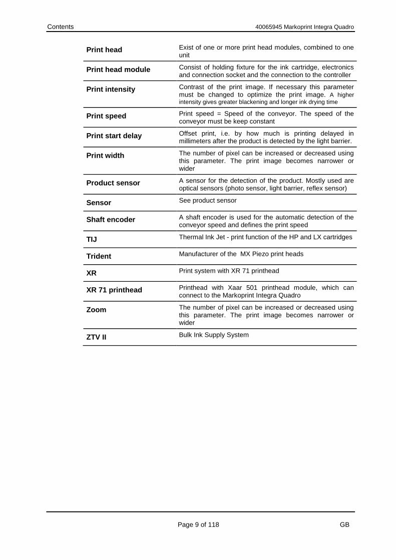
Print head Exist of one or more print head modules, combined to one unit
Print head module Consist of holding fixture for the ink cartridge, electronics and connection socket and the connection to the controller
Print intensity Contrast of the print image. If necessary this parameter must be changed to optimize the print image. A higher
intensity gives greater blackening and longer ink drying time
Print speed Print speed = Speed of the conveyor. The speed of the conveyor must be keep constant
Print start delay Offset print, i.e. by how much is printing delayed in millimeters after the product is detected by the light barrier.
Print width The number of pixel can be increased or decreased using this parameter. The print image becomes narrower or wider
Product sensor A sensor for the detection of the product. Mostly used are optical sensors (photo sensor, light barrier, reflex sensor)
Sensor See product sensor
Shaft encoder A shaft encoder is used for the automatic detection of the conveyor speed and defines the print speed
TIJ Thermal Ink Jet - print function of the HP and LX cartridges
Trident Manufacturer of the MX Piezo print heads
XR Print system with XR 71 printhead
XR 71 printhead Printhead with Xaar 501 printhead module, which can connect to the Markoprint Integra Quadro
Zoom The number of pixel can be increased or decreased using this parameter. The print image becomes narrower or wider
ZTV II Bulk Ink Supply System

General 40065945 Markoprint Integra Quadro
Page 10 of 118 GB
Customer Service
Please contact your local distributor for technical information. If failures at the print system occur, you should be prepared with the following information:
Detailed error description.
All information on the name plate of the print system.
Version number of the system software and of the iDesign Software
Configuration (Print, Basic, Advanced, Pro)
Special functions of the software or hardware
When did the error occur for the first time? Prior to call our hotline service, please have a look at the manual ( Chapter Faults, page 80) for potential references to eliminate the error. Furthermore, our staffs are always interested in new information and experiences with the use of the product and which may be valuable for improvements to our products.

Safety Regulations 40065945 Markoprint Integra Quadro
Page 11 of 118 GB
Safety Regulations
Behavior in Case of an Emergency
The operating personnel have to be familiar with the operation and the location of safety, accident notification-, first aid- and rescue devices. What to do in Case of an Emergency?
Initiate immediately all required emergency measures for injured persons. Observe valid safety regulations in any case in order to avoid further damages to persons.
Call medical attendance for injured persons.
Eliminate all accident causes.
General Safety Regulations
Safety regulations provide information in written and symbol form in order to warn you against dangers and to instruct you to avoid any damage to persons or to properties. Safety regulations are started by signal words indicating the level of danger. Safety regulations may be placed directly at the print system or in documents about this print system.
Explanation of Danger Degrees
This symbol indicates a hazardous situation which, if not avoided, will result in death or serious injury. All safety regulations have to be observed to avoid any damage to persons.
This symbol indicates a hazardous situation which, if not avoided, could result in death or serious injury. All safety regulations have to be observed to avoid any damage to persons.
This symbol indicates a hazardous situation which, if not avoided, may result in minor or moderate injury. All safety regulations have to be observed to avoid any damage to persons.
This symbol indicates a hazardous situation which, if not avoided, may result in damage to properties. All safety regulations have to be observed to avoid any damage to properties.

Safety Regulations 40065945 Markoprint Integra Quadro
Page 12 of 118 GB
Intended Use
The working reliability of the print system is ensured only with intended use. The Markoprint Integra Quadro has been designed, built and must be used exclusively for the intended purpose described. The Markoprint Integra Quadro serves to create print images and print them from the top or side to smooth and absorbent product surfaces. The product must pass the print head, i.e. by a conveyor belt. All working conditions and instructions, prescribed in this manual, will be observed. Any use beyond the intended use or any alternative use of the equipment is regarded as misuse and may lead to hazardous situations. Misuse of the device may lead to hazardous situations. Refrain, in particular, from subjecting the apparatus to the following: Modification, retrofitting or alteration of the apparatus or individual sub-assemblies. Any claims arising from damages due to undesignated use are rejected.

Safety Regulations 40065945 Markoprint Integra Quadro
Page 13 of 118 GB
Reasonably Foreseeable Misuse
Another use as fixed in the „Intended Use“ or even more applies as not intended! For damages caused by not intended use
The operator bears the complete responsibility,
The manufacturer assumes no liability. If you do not use the system according to the regulations, risks may occur! Not intended uses are e.g.:
operation in explosive atmosphere
the print system comes in contact with food …
Retrofitting and Changes at the Print System
Unauthorized retrofitting and changes at the system lead to an immediate expiration of liability and warranty covered so far by the manufacturer! This is also valid for interventions and program changes at programmable control systems as well as program changes at control units as far as they are not described in this Manual. The electromagnetic performance of the system can be affected by amendments or changes of any kind. Do not arrange any changes or amendments at the systems without consultation and written approval of the manufacturer.
Warning Notices at Print System
Particular sources of danger at the print system are marked by yellow labels. The used pictograms point out to following dangers:
Danger to Life

Safety Regulations 40065945 Markoprint Integra Quadro
Page 14 of 118 GB
Special hazards
The following section identifies the remaining risks, determined following a risk analysis. Observe the safety notes listed here and the warnings in other chapters of the manual to minimize health hazards and avert hazardous situations.
Danger to life through electric shock!
DANGER TO LIFE!
Contact with live parts poses imminent danger to life. Damaged insulation or individual components can be lethal.
Therefore:
– Immediately switch off the power supply and initiate repairs if the insulation is damaged.
– Work on the electrical system may only be performed by electricians.
– Before working on the electrical system, disconnect from the mains (remove mains plug) and check that power is off.
– Always disconnect mains before performing cleaning and repair tasks.
– Keep moisture from live parts. Moisture may cause a short-circuit.
Risk of injury through incorrect handling of batteries!
RISK OF INJURY!
Rechargeable and primary batteries contain toxic heavy metals. They must be treated as special refuse and deposited at municipal collection points or be disposed of by a specialized company. Batteries must be handled with particular care.
Therefore:
– Never throw batteries into a fire or subject batteries to high temperatures. Explosion hazard.
– Do not charge batteries. Explosion hazard.
– Fluid escaping through incorrect use may cause skin irritations. Avoid contact with the fluid. In case of contact with the fluid, rinse with ample water. If the fluid comes into contact with the eyes, rinse immediately with water for 10 minutes and consult a doctor without delay.

Safety Regulations 40065945 Markoprint Integra Quadro
Page 15 of 118 GB
Edges and corners pose risk of injury!
RISK OF INJURY!
Sharp edges and pointed corners may cause abrasions and cuts to the skin.
Therefore:
– Be cautious when working near sharp edges and pointed corners.
– If in doubt, wear protective gloves.
Risk of stumbling posed by dirt, objects lying about and connecting lines!
RISK OF INJURY!
Dirt, objects lying about and connecting lines for power, data- and signal lines may cause slipping and stumbling resulting in severe injuries.
Therefore:
– Always keep working area clean.
– Remove objects no longer required.
– Mark stumbling areas with yellow-black marking tape.
– Non tension connecting lines to system and pass it that no places of danger do arise.

Safety Regulations 40065945 Markoprint Integra Quadro
Page 16 of 118 GB
Remaining Risks
The print system is constructed for a safe operation. Hazards that are not preventable due to construction purposes are limited as far as possible by protection devices. A certain amount of risk is always existent! The knowledge about the remaining risks assists you to arrange your work safer and to avoid incidents. In order to avoid the dangers, please observe additionally the particular security advice in the single chapters.
Disposal
This print system complies with the RoHS EU-Regulation 2011/65/EU with observance of the fixed using prohibitions and avoiding pollutants.
Authorized persons
Work at the print system should only be performed by reliable personnel. Please comply with the legal age! Only trained personnel are allowed to operate the print system. Trainees, apprentices etc. must be supervised by an experienced person while working at the print system. Prior to start running the labeler the operator has to ensure that the manual of the labeler is available to all users of the machine and that the users have read and understood the manual. Only then the system may be put in operation. The responsibility for the different tasks at the print system must be clearly specified and kept. There must be no ambiguous authorities for this may put the safety of the users at risk. Arrange a detailed work schedule if several persons work on the machine. All work on the electrical equipment must be carried out by skilled electricians only. Failures may be eliminated by authorized personnel only. All work associated with the assembly, adjustment and maintenance at the machine may be carried out only by trained or instructed personnel. The operator of the machine must ensure that the personnel are trained in dealing with the integrated control system prior to fix machine errors or maintain the system.

Safety Regulations 40065945 Markoprint Integra Quadro
Page 17 of 118 GB
Personal protective equipment
Wear following protective equipment when performing work at the system:
SAFETY SHOES
Wear for protection against falling off parts and slipping.
PROTECTIVE CLOTHING
Are tight-fitting clothes with low tensile strength, with tight sleeve
and without distant parts
Wear a hairnet if applicable
Do not wear jewelry or wrist watches
PROTECTIVE GOGGLES
For protection against splashes of detergents and flying parts
SAFETY GLOVES
For protection against sharp-edged items
Personal Protective Equipment for the following tasks
Protective Clothing
Safety Shoes
Safety Gloves
Protective Goggles
Transport x x x
Setting up and connecting of the system
x x x x
Maintenance Work x x x
The documentation of the manufacturer of the single system components has to be observed!

Safety Regulations 40065945 Markoprint Integra Quadro
Page 18 of 118 GB
Working Places Operator Personnel
The print system is an automatic working system and does not require any operation for the print procedure.

Technical data 40065945 Markoprint Integra Quadro
Page 19 of 118 GB
Technical data
General specifications
Weight 1045 g
Length 130 mm
Width 208 mm
Height behind 73,3 mm
* all specifications excl. bracket and connections
Connection parameters electrical
Input voltage 24 V DC
Current consumption, maximum
4 A
Power consumption, maximum
100 W
Protection class IP 40D
Standby power input <10 W
Power supply Electrical
Input voltage at the power supply
90 to 240 V AC
Frequency power supply 50 to 60 Hz
Power consumption, maximum
0,5 A
Current consumption, maximum
80 W
Protection class IP 40D
Standby power input <18 W

Contents 40065945 Markoprint Integra Quadro
Page 20 of 118 GB
Data interfaces
USB USB A
USB USB B
Ethernet RJ45
RS 232 Sub-D 9-Pol Stecker
Sensor 24V ±10% < 100mA
Encoder 24V ±10% < 100mA
USB 5V ±10% < 100mA
Supply voltage 24V +- 10%
The switching threshold of the inputs is 12V ± 2V. The sensors / encoders must be designed for 24V operating voltage. E.g. 24V + - 10% or 10V – 30V The inputs are NPN as standard, but can be rejumpered to PNP with the iDesign software.

Technical data 40065945 Markoprint Integra Quadro
Page 21 of 118 GB
Performance data
Cable length Power supply
(other lengths on request)
Cable length for print head
Max. Length of the head cable HP
Max. Length of the head cable LX
Max. Length of the head cable MX or XR
Max. Length LAN
2
3
13
50
50
50
m
m
m
m
m
m
Text layout Software iDesign
Parameter input iLOGIK at the device / Software idesign8
Screen OLED display 128 x 68 pixel self-illuminated, 2,5“ diagonal
Fonts
(optional)
all available Windows fonts
print fonts for variable data
customer-specific fonts
Print height with HP print heads, LX-print heads
1 to 50 mm
Print height with MX print heads 3 to 400 mm
Print height with XR print heads 1 to 284 mm
Max. horizontal resolution with HP print heads or LX print heads
900 dpi
Max. horizontal resolution with MX or XR print heads
600 dpi
Vertical print resolution in dpi
HP / LX print heads:
MX print heads:
XR print heads:
300 / 600
192 / 64 (channel)
180
User language
Device:
Software:
German, English, French, further on request
German, English, French, further on request
Barcodes 2D-Codes
EAN 8, EAN 13, EAN 128, 2/5 ITF, 2/5 with check Code 128, UPC A, UPC E
GS1-Datamatrix, Datamatrix, QR-Code
Technical data 40065945 Markoprint Integra Quadro
Page 22 of 118 GB
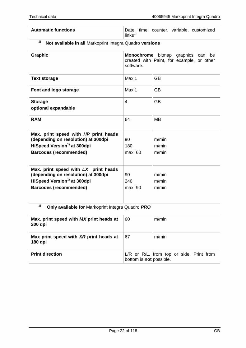
Automatic functions Date, time, counter, variable, customized links1)
1) Not available in all Markoprint Integra Quadro versions
Graphic Monochrome bitmap graphics can be created with Paint, for example, or other software.
Text storage Max.1 GB
Font and logo storage Max.1 GB
Storage
optional expandable
4 GB
RAM 64 MB
Max. print speed with HP print heads (depending on resolution) at 300dpi
HiSpeed Version1) at 300dpi
Barcodes (recommended)
90
180
max. 60
m/min
m/min
m/min
Max. print speed with LX print heads (depending on resolution) at 300dpi
HiSpeed Version1) at 300dpi
Barcodes (recommended)
90
240
max. 90
m/min
m/min
m/min
1) Only available for Markoprint Integra Quadro PRO
Max. print speed with MX print heads at 200 dpi
60 m/min
Max print speed with XR print heads at 180 dpi
67 m/min
Print direction L/R or R/L, from top or side. Print from bottom is not possible.

Transport, Packaging and Storage 40065945 Markoprint Integra Quadro
Page 23 of 118 GB
Transport, Packaging and Storage
Transport
Check the delivery for completeness and transport damages immediately upon receipt. Proceed as follows in case of externally visible transport damage:
Decline delivery or accept with reservation only.
Record extent of damage in the transport documentation or on the delivery note of the carrier.
Initiate complaint.
Scope of delivery
The scope of delivery of the Markoprint Integra Quadro depends on the ordered options and the customer’s application. Please control the scope of delivery when receiving the systems on the basis of the delivery note. Scope of Delivery - Basic:
1x Markoprint Integra Quadro control system
1x CD, content: Chapter USB-Stick , page 95
1x Operation manual (CD)
1x iDesign-Software (CD)
1x USB-cable A-B
1x Grounding cable
Optional:
Power supply
Print head: HP-print head, LX-print head, MX-print head or XR print head
Print head cable
Mounting bracket
Photo sensor
Shaft encoder
Alarm light

Transport, Packaging and Storage 40065945 Markoprint Integra Quadro
Page 24 of 118 GB
Symbols on packaging
As part of the installation and further use it may happen that the operator put user or maintenance personnel in charge of handling of packages. Therefore note the following important notes.
This way up
The arrowheads indicate the top of the package. They must always face upward to avoid damage to the content.
Fragile
Identifies packages with fragile or sensitive contents. Handle the package with care, do not drop or subject to impacts.
Keep dry
Keep packages away from moisture and keep dry.
Protect from heat
Protect packages from heat and direct sunlight.
Transport und Unpacking
Safety Instructions
Material damage due to incorrect transport!
Remove the packaging material and the transportation safety devices on installation site and transport the print system in its original packaging to the place of installation.
Danger due falling parts!
– Wear safety shoes!

Transport, Packaging and Storage 40065945 Markoprint Integra Quadro
Page 25 of 118 GB
Packaging
On packaging
The individual packages are packed in accordance with the expected transport conditions. Only environmentally-friendly materials were used for packaging. Packaging serves to protect the individual components against transport damage, corrosion and other damage, up to the assembly stage. Do not, therefore, damage the packaging - remove shortly before assembly only.
Original packaging is available from the manufacturer to ensure optimal dispatch of the device. Please contact your local distributor.
Handling of packaging materials
Dispose of packaging material in accordance with the applicable statutory provisions and local regulations.
Environmental damage!
Packaging materials are valuable raw materials and can, in many cases, be re-used or profitably recycled and re-used.
Therefore:
– Dispose of packaging materials in an environmentally-responsible manner.
– Observe the locally applicable disposal regulations. If necessary, commission a specialized company for disposal.

Transport, Packaging and Storage 40065945 Markoprint Integra Quadro
Page 26 of 118 GB
Storage control system
Store the controller under the following conditions:
Do not store outdoors.
Keep dry and free of dust.
Do not expose to aggressive media.
Keep away from direct sunlight.
Avoid mechanical shock.
Storage temperature: 5°C to 45°C.
Relative humidity: maximum 60 %.

Assembly and function 40065945 Markoprint Integra Quadro
Page 27 of 118 GB
Assembly and function
Brief description
The Markoprint Integra Quadro, of Weber Marking Systems GmbH is a controller, which can drive ink jet print heads for product identification. The Markoprint Integra Quadro can control both thermal and piezoelectric print heads. The Markoprint Integra Quadro permit a wide range of print images on products, i.e. product descriptions, graphics, quantities, best before dates, barcodes and serial number. Print layouts can be created with the included iDesign software and can send via network connection or USB interface or USB stick to the Markoprint Integra Quadro.
Controller
The Markoprint Integra Quadro controller consists of:
The electronics inside the housing
The iLOGIK controller for parameter input and settings
Four membrane keys for print head selection and to make settings
One OLED display
The connectors on the system back for power supply, encoder, photo sensor and other in-/outputs
The Markoprint Integra Quadro can be used as a built-in device (e.g. control cabinets) and can also be mounted directly on a system. The existing 24V power supply can be used in the control cabinet. An additional 24V power supply unit is required for installation on the production line.
.

Assembly and function 40065945 Markoprint Integra Quadro
Page 28 of 118 GB
System versions
The Markoprint Integra Quadro is available as standard version Advanced and as Pro-Version with extended functions. Functions Markoprint Integra Quadro Advanced: Print speed up to 90m/min with HP at 300dpi, counter, date with best before, variable input, 2D barcodes, 1m print length (up to 2 m at 300 dpi without zoom optimization), data backup with USB-Stick, interface functions, data base connection. Functions Markoprint Integra Quadro Pro: Like Markoprint Integra Quadro Advanced extra: Hi-Speed adjustable with print speed up to 240 m/min with LX at 300 dpi, up to 3m text length (up to 2 m at 300 dpi without zoom optimization), password protection. The Markoprint Integra Quadro control systems will be delivered as Advanced version standard. If the requirements exceed the scope of services of the Advanced version, an upgrade with costs to the Pro version is available. See also Chapter Software-Upgrade, page 94.

Assembly and function 40065945 Markoprint Integra Quadro
Page 29 of 118 GB
Overview Markoprint Integra Quadro Steuergerät
Fig. 1: Controller
No. Description
1 DISPLAY
2 INDICATOR LIGHTS
3 BUTTONS FOR HEAD SELECTION
4 ILOGIK BUTTON
5 USB A SOCKET
6 USB B SOCKET
7 ETHERNET SOCKET
8 RS232 SOCKET
9 24V DC VOLTAGE INPUT
10 OPTIONAL IN-/OUTPUTS
11 PRINTHEAD CONNECTIONS
12 ALARM CONNECTIONS
13 SENSOR INPUTS
14 ENCODER INPUTS
2
5
4
3
11
12
13
14
10 1
6
7 8
9

Assembly and function 40065945 Markoprint Integra Quadro
Page 30 of 118 GB
Nameplate
Fig. 2: Name plate
The nameplate is attached to the bottom of the device and displays the following:
System type
Serial number
MAC-address
Article number
Supply voltage
Power consumption
Address of manufacturer

Installation and initial operation 40065945 Markoprint Integra Quadro
Page 31 of 118 GB
Installation and initial operation
Safety notes
Danger to life through electric shock!
DANGER TO LIFE!
Contact with live parts poses imminent danger to life. Damaged insulation or individual components can be lethal.
Therefore:
– Immediately switch off the power supply and initiate repairs if the insulation is damaged.
– Work on the electrical system may only be performed by electricians.
– Before working on the electrical system, disconnect from the mains (remove mains plug) and check that power is off.
– Always disconnect mains before performing cleaning and repair tasks.
– Keep moisture from live parts. Moisture may cause a short-circuit.
Risk of stumbling posed by dirt, objects lying about and connecting lines!
RISK OF INJURY!
Dirt, objects lying about and connecting lines for power, data- and signal lines may cause slipping and stumbling resulting in severe injuries.
Therefore:
– Always keep working area clean.
– Remove objects no longer required.
– Mark stumbling areas with yellow-black marking tape.
– Non tension connecting lines to system and pass it that no places of danger do arise.

Installation and initial operation 40065945 Markoprint Integra Quadro
Page 32 of 118 GB
Edges and corners pose risk of injury!
RISK OF INJURY!
Sharp edges and pointed corners may cause abrasions and cuts to the skin.
Therefore:
– Be cautious when working near sharp edges and pointed corners.
– If in doubt, wear protective gloves.

Installation and initial operation 40065945 Markoprint Integra Quadro
Page 33 of 118 GB
Installation
Only an optimally aligned installation of the system can ensure a continuous operation with a low rate of failures and a minimum wear. For an optimized installation of the system, fine tunings adapted to environmental conditions are essential. For the fine tunings, a complex expert knowledge is required basing on experience with print technique. The complexity of a wear-optimized installation requires a high measure of specialized knowledge and experience, which cannot be obtained completely by reading this manual. Therefore the installation of the print system must be made by a technician from your local distributor or examined by a final inspection. Damage or damages based on an incorrect installation, represent no case of warranty.
Requirements to the Site of Installation
When choosing the installation location the following conditions apply:
Consider the generally accepted ergonomic criteria in accordance with workplace ordinances as well as country-specific legislation.
The installation location must be a dry and dust-free room, ideally with an ambient temperature of approx. 18…25 °C.
The installation location may not be subject to fast temperature fluctuations (condensation!).
Do not set up the controller directly next to or above hot surfaces, since this will affect cooling of the controller.
If the controller is operated on a tripod (accessory), the stability of the tripod on an even foundation must be ensured.
The controller may not be exposed to flammable, explosive, corrosive gases or chemical vapors.
The controller may not be installed in the vicinity of high voltage equipment or power supplies.
The controller may not be subjected to direct vibrations or shocks.
Keep controller away from oil or water.
The controller may not be exposed to strong magnetic or electric fields.
Placing the control system
The installation position has to provide sufficient access for user and service technician. The power plugs must be easy to access to cut the voltage anytime.
Observe that all mounting parts are fixed sufficiently.
Consider all points of the "Intended Use" in the chapter safety regulations.
To achieve a clean, sharp print result the distance from the product to be printed to the cartridge nozzle plate is important. The optimum distance is 0 to 4 mm between the deflector and the product. A greater distance will adversely affect the print result, particularly at high conveyor belt speeds. The higher the print speed the shorter must be the distance. At speeds of less than 20 m/min a distance of up to 4 mm between the nozzle plate and the product may still be acceptable.

Installation and initial operation 40065945 Markoprint Integra Quadro
Page 34 of 118 GB
Positioning the Control System
Material damage due to improper print system installation!
With the print system switched on, a defect may occur in the system electronics.
Therefore:
– Only install the system when it is switched off.
– Network cables only connect or disconnect if the power supply is dead voltage.
Material damage due to induced currents!
If the connection cables of the controller run close to high voltage or heavy current cables in the cable duct, induction may cause malfunctioning or damage.
Therefore:
– Lay all connection cables of the controller spatially separate from high voltage and heavy current cables.
Material damage due to an incorrect control system installation!
Faults on the control system can happen by potential differences between control system and conveyor belt.
Therefore:
– An electro-conductive connection between control system and conveyor belt must be established.
Material damage due to not properly installed connecting cables!
Improper installation of the connecting cables can cause damages to these.
Therefore:
– When laying the cables, ensure that cables are not tripping hazards and do not lay them around corners and sharp edges. Avoid abrasive surfaces.

Installation and initial operation 40065945 Markoprint Integra Quadro
Page 35 of 118 GB
Required Resources Setscrew wrench (Allen key®) SW5 Instruction Please install the control system as follows:
Step Procedure
1 Set up the controller …
on an even and adequately load-bearing surface
Install it on a production line
Fasten to a top-hat rail in the control cabinet
Install it on a wall
For mounting the control on a production line or wall mounting, flanges with holes are provided on the sides.
2 Connect the control system with the conveyor belt electro-conductive.
Installation of the print heads
For information on mounting the print heads, refer to the respective operating instructions of the print head.

Installation and initial operation 40065945 Markoprint Integra Quadro
Page 36 of 118 GB
Connecting the control system
The Print system needs electricity for its functions. Please find more details in the chapter “Technical Data“.
Connecting to Supply Voltage
Requirements 24V power supply 4A or power supply with M12 socket available. Instruction Please connect the control system with voltage connection as follows:
Step Procedure
1 Compare the mains data with the technical data of the control system. Chapter Technical data, page 19 Make electrical connections only if they match!
2 Connect the M12 socket to the M12 connection of the control unit.
Fig. 3: Voltage connection control unit

Installation and initial operation 40065945 Markoprint Integra Quadro
Page 37 of 118 GB
Connecting of the Print heads
Requirements The print head is mounted on a production line.
Instruction Please connect the print head with the control system as follows:
Step Procedure
1 Connect the print head cable of the first head (top head in a cascaded installation) to the HEAD 1 socket and tighten.
Fig. 4: Print head connection socket at the front of the control system
2 Optional: connect the printhead cable of the second head and further heads to the corresponding sockets and screw them tight.
If you only want to print with one print head, the other connections remain unassigned.

Installation and initial operation 40065945 Markoprint Integra Quadro
Page 38 of 118 GB
Connecting the optional Shaft Encoder
Requirements
The optional shaft encoder is mounted at the production line.
Ideally runs the measuring wheel of the shaft encoder on the conveyor belt, near the print system.
The encoder is activated in the system menu.
Instruction Please connect the optional shaft encoder with the control system as follows:
Step Procedure
1 If necessary install the optional shaft encoder on the production line and connect it to the Encoder socket.
Fig. 5: Encoder socket (M8 4-pole) at the front of the control system
In addition, a second encoder can be connected to the Markoprint Integra Quadro. This allows two different speeds to be used by two different lines. To do this, connect the second encoder to the Encoder 3+4 connector.
Connecting the optional Product Sensor
Requirements
The optional shaft encoder is mounted at the production line.
Between the sensor and the nozzle plate is maximum a product, because another print activation is otherwise ignored.
Instruction Please connect the optional product sensor with the control system as follows:
Step Procedure
1 If necessary install the optional shaft encoder on the production line and connect it to the Sensor socket.
Fig. 6: Sensor socket (M8 4-pole) at the front of the control system
In addition, it is possible to connect a second product sensor to the Markoprint Integra Quadro. As a result, two different products from two different lines can be used. To do this, connect the second product sensor to the connection sensor 3+4.

Installation and initial operation 40065945 Markoprint Integra Quadro
Page 39 of 118 GB
Connecting the optional Alarm Light
Requirements The optional alarm light is mounted at the production line. Instruction Please connect the optional alarm light with the control system as follows:
Step Procedure
1 If an alarm light (accessory) is installed, connect the alarm light cable to the Alarm socket and tighten.
Fig. 7: Alarm socket (M12) at the front of the control system
In addition, it is possible to connect a second alarm light to the Markoprint Integra Quadro. As a result, two different products from two different lines can be used. To do this, connect the second alarm light to the connection Alarm 3+4.

Installation and initial operation 40065945 Markoprint Integra Quadro
Page 40 of 118 GB
Connection for optional Inputs / Outputs
Requirements The cabling of the socket is connected according the requirements.
Instruction Please connect the optional inputs with the control system as follows:
Step Procedure
1 Connect and tighten the input cable to the Extern socket, if external inputs are installed.
Fig. 8: Extern socket (Sub-D 25-pole) on the side of the control system
Connection to a network
A RJ-45-connection allows a connection of the print system to the customer LAN (Local Aera Network). The LED on the top of the system lights green if a network is available. The LED flashes yellow with data communication. Instruction Please connect the control system with the network as follows:
Step Procedure
1 If required connect the print system to the network by a RJ45 socket.
Fehler! Es ist nicht möglich, durch die Bearbeitung von Feldfunktionen Objekte zu erstellen.
Fig. 9: Ethernet socket (RJ 45) on the side of the control system
Each IP address can place in a network once only. Otherwise there is an address conflict and the system can’t address. Please contact your system administrator.

Installation and initial operation 40065945 Markoprint Integra Quadro
Page 41 of 118 GB
Configuration of the print technology
The Markoprint Integra Quadro can control the print technologies HP, LX and MX. The Markoprint Integra Quadro has two channels, which provide a combination of the different print technologies. After the system has been installed, the configuration of the print technologies is shown and can set up with the first switch on ( Chapter Switch on, page 43). The configuration of the selectable print technologies is possible like shown in the following list.
Configuration of channels
1+2 – 3+4 Description
HP – HP The device controls at only HP print head modules. Up to four print head modules can be controlled.
HP – MX The device controls up to two HP print head modules and up to two MX print head modules.
HP - XR The device controls up to two HP print head modules and up to two XR print head modules.
MX – MX The device controls at only MX print head modules. Up to four print head modules can be controlled.
MX – LX The device controls up to two MX print head modules and up to two LX print head modules.
MX - XR The device controls up to two MX print head modules and up to two XR print head modules.
LX – LX The device controls at only LX print head modules. Up to four print head modules can be controlled.
LX - HP The device controls up to two LX print head modules and up to two HP print head modules.
LX - XR The device controls up to two LX print head modules and up to two XR print head modules.
The Markoprint Integra Quadro control system is configured to HP – HP standard by the delivery and can customize to the desired configuration if needed.
Requirements
The print system is correct installed.
The print system is connected to the power supply.
Instruction
Please adjust the configuration of the print technology as follows:
Step Procedure
1 Switch the system on. Chapter Switch on / Switch off, page 43
2 The display shows the company logo and changes to the configuration menu.

Installation and initial operation 40065945 Markoprint Integra Quadro
Page 42 of 118 GB
Fig. 10: Configuration menu print technology
3 Set the desired print technology for channel 1 (Chan1) by the iLOGIK and confirm the selection by pressing the iLOGIK.
4 S Set the desired print technology for channel 2 (Chan2) by the iLOGIK and confirm the selection by pressing the iLOGIK.
5 The selection is on Ok? after the desired configuration. Set the value to Yes by rotating the iLOGIK and confirm by pressing.
6 The system restarts and reboot in the adjusted configuration.
If a system is false configured or should be reconfigured, the start display can be reactivated for the configuration of the print technology.
Instruction
Please call up the print technology configuration as follows:
Step Procedure
1 Touch the iLOGIK once in one of the status menus. The Label Submenu is displayed.
2 Call the System Submenu by rotating the iLOGIK. The System Submenu is displayed.
3 Press the head selection-button [1] and the iLOGIk at the same time. The display shows a waiting picture shortly and returns to the System Submenu automatically.
4 Switch the system off. Chapter Fehler! Verweisquelle konnte nicht gefunden werden. /
Switch off, page Fehler! Textmarke nicht definiert.
5 Switch the system on. Chapter Fehler! Verweisquelle konnte nicht gefunden werden. /
Switch off, page 43
6 Configure the system like described above.

Operation 40065945 Markoprint Integra Quadro
Page 43 of 118 GB
Operation
Switch on
Requirements
The print system is connected with power.
Instruction
Please switch the print system on as follows:
Step Procedure
1 Switch on the power supply.
2 The controller must conduct a self-test and briefly indicates the unit version number after the company logo has passed through the display. After approx. 20 seconds the status menu-1 appears on the display.
When starting the system unit the progress of the starting process can be monitored on the LED’s. If errors occur during booting, an error code is transmitted via the LED’s and can be analysed in more detail. Chapter Fehler! Verweisquelle konnte nicht gefunden werden., page Fehler! Textmarke nicht definiert. The configuration of the print technology must be set with the initial operation. Here the system doesn’t boot up completely for now, first the configuration of the print technology must performed. Chapter Configuration of the print technology, page 41
Switch off
Requirements
The print system is connected with power and switched on
Instruction
Please switch the print system off as follows:
Step Procedure
1 Switch off the power supply.
If MX print heads are used, they can be switched off separately at the maintenance station. When the control unit is switched off, the MX print heads are also switched off, only the maintenance station must be switched off separately.

Operation 40065945 Markoprint Integra Quadro
Page 44 of 118 GB
iLOGIK operation
The iLOGIK is a turn and press switch which enables the operator to move within the menu and make adjustments. The menu functions are shown on a display located above the iLOGIK.
Turn: Moving in the menu structure tree and changing set values and parameters after the selection is made.
Press: A short press on the iLOGIK calls a selected function and sets / actuates the previously set value. Longer pressing (> 1 sec.) of the iLOGIK enables the operator to jump back to the previous menu level.
After two minutes without input, the unit automatically switches to status display. After a further five minutes, the screen saver is activated. The display returns to status menu-1 by pressing or rotating the iLOGIK
Fig. 11: Operating the iLOGIK

Operation 40065945 Markoprint Integra Quadro
Page 45 of 118 GB
Print head module selection
The separate print head modules can be selected by the buttons 1 to 4, underneath the display. It’s possible to scan the status of the respective print head module and to set up the parameters of the respective ink cartridges / print head modules. The selected print head module will be shown by a LED in the respective button field. The LED glows green. Is the print head made up of multi-print head modules, the LED buttons of the corresponding print head modules will lighten yellow. The LED buttons of the other print head modules, which are not a part of the print head, are lapsed. Example: Two Twin print heads are connected to the controller. If one print head module is selected, the LED glow green and the LED of the other print head module yellow. The LED of the second Twin print head is lapsed.

Bedienung 4006594516 Markoprint X4JET
Page 46 of 118 GB
Indicator lights
LED’s, which light up in different colours according to the operating mode, are located on the right and underneath the display. The LED’s for status sensor and network are characterized with symbols. The meaning of the different coloured messages is explained in the table below.
Fig. 12: Indicator lights
No. Description
1 STATUS SENSOR 1 & 2
2 STATUS SENSOR 3 & 4
3 NETWORK
4 STATUS PRINT HEAD 1 TO 4
5 SELECTION PRINT HEAD MODULE
1
2
3
4
5

Bedienung 4006594516 Markoprint X4JET
Page 47 of 118 GB
Symbol Function Description Reason
Sensor-LED 1+2 3+4
GREEN: Busy YELLOW: Start signal present RED: Failure Flashing
Lights from start to print end No print text No encoder signal Encoder too fast
Network-LED GREEN: O.K. YELLOW: Busy RED: Failure
Connected Data transfer
Head status-LED
GREEN: O.K. YELLOW: Busy RED: Failure
Ready Prints i.e. empty cartridge
Head selection-LED
GREEN: Selected cartridge YELLOW: Print head related cartridge/-s
Select Display print head belonging

Operation 40065945 Markoprint Integra Quadro
Page 48 of 118 GB
Menu structure

Operation 40065945 Markoprint Integra Quadro
Page 49 of 118 GB
Display Menu Description
Status menu 1
Cartridges
The ink filling level in the ink cartridge and the name of the currently loaded print image (her: cow) is displayed. If the print status is set to pause, the text name >>Pause<< appears instead.
Display/Setting for selected print head module
Status menu 2
Act. Prints: Number of prints actually printed
Text/Cart.: Number of prints of the loaded text per ink cartridge
Display/Setting for selected print head module
Print image preview
The text currently loaded can be viewed in the print preview. To do this: Rotate iLOGIK button until the print preview appears and confirm by pressing. The entire print image can now be observed by scrolling.
Display/Setting for selected print head module
Label Texts stored in the memory can be selected for printing in this menu of the Markoprint Integra Quadro and a print pause can be set.
Chapter Fehler! Verweisquelle konnte nicht gefunden werden., Page Fehler! Textmarke nicht definiert.
Display/Setting for selected print head module
Select label In this submenu the desired text can be selected from the list of stored texts by turning and briefly pressing the iLOGIK.
Printing? Confirming the selected text by briefly pressing the iLOGIK or by switching to pause mode by turning the iLOGIK.
Pause? Confirming the pause mode by briefly pressing the iLOGIK.
Parameter Print start delay, print speed, intensity, print width, print direction, selection of nozzle row and upside down print can be set in this menu
Print Delay The print start delay can be set in this menu, i.e. by how much is printing delayed in millimetres after the product is detected by the light barrier
Chapter Print start delay, Page 55
Speed If the product speed is extremely uniform, the use of the rotary encoder may be dispensed with. For this purpose, the speed can be set in the Speed submenu by setting Encoder Intern in the system menu.
NOTE: This menu is just available when Encoder Intern is set in the menu.
Chapter speed, Page 57
Operation 40065945 Markoprint Integra Quadro
Page 50 of 118 GB
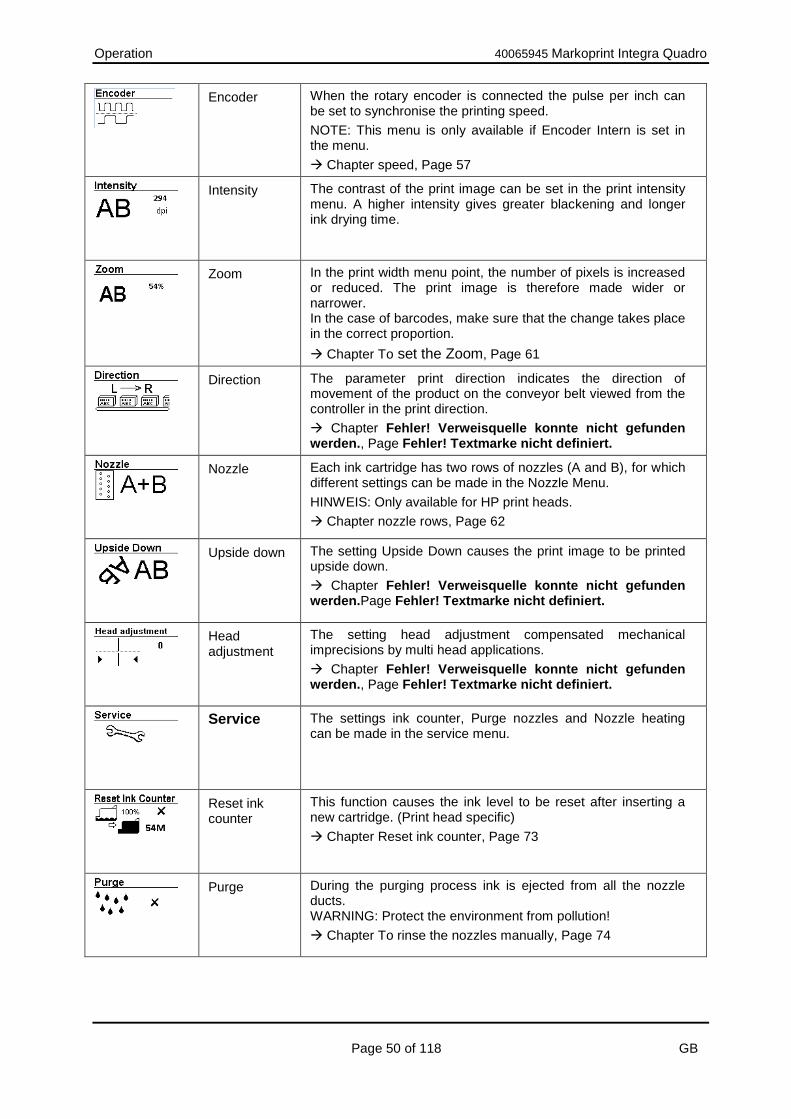
Encoder When the rotary encoder is connected the pulse per inch can be set to synchronise the printing speed.
NOTE: This menu is only available if Encoder Intern is set in the menu.
Chapter speed, Page 57
Intensity The contrast of the print image can be set in the print intensity menu. A higher intensity gives greater blackening and longer ink drying time.
Zoom In the print width menu point, the number of pixels is increased or reduced. The print image is therefore made wider or narrower. In the case of barcodes, make sure that the change takes place in the correct proportion.
Chapter To set the Zoom, Page 61
Direction The parameter print direction indicates the direction of movement of the product on the conveyor belt viewed from the controller in the print direction.
Chapter Fehler! Verweisquelle konnte nicht gefunden werden., Page Fehler! Textmarke nicht definiert.
Nozzle Each ink cartridge has two rows of nozzles (A and B), for which different settings can be made in the Nozzle Menu.
HINWEIS: Only available for HP print heads.
Chapter nozzle rows, Page 62
Upside down The setting Upside Down causes the print image to be printed upside down.
Chapter Fehler! Verweisquelle konnte nicht gefunden werden.Page Fehler! Textmarke nicht definiert.
Head adjustment
The setting head adjustment compensated mechanical imprecisions by multi head applications.
Chapter Fehler! Verweisquelle konnte nicht gefunden werden., Page Fehler! Textmarke nicht definiert.
Service The settings ink counter, Purge nozzles and Nozzle heating can be made in the service menu.
Reset ink counter
This function causes the ink level to be reset after inserting a new cartridge. (Print head specific)
Chapter Reset ink counter, Page 73
Purge During the purging process ink is ejected from all the nozzle ducts. WARNING: Protect the environment from pollution!
Chapter To rinse the nozzles manually, Page 74
Operation 40065945 Markoprint Integra Quadro
Page 51 of 118 GB
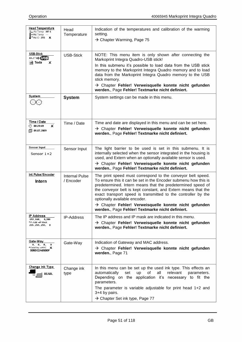
Head Temperature
Indication of the temperatures and calibration of the warming setting.
Chapter Warming, Page 75
USB-Stick NOTE: This menu item is only shown after connecting the Markoprint Integra Quadro-USB stick!
In this submenu it’s possible to load data from the USB stick memory to the Markoprint Integra Quadro memory and to load data from the Markoprint Integra Quadro memory to the USB stick memory.
Chapter Fehler! Verweisquelle konnte nicht gefunden werden., Page Fehler! Textmarke nicht definiert.
System System settings can be made in this menu.
Time / Date Time and date are displayed in this menu and can be set here.
Chapter Fehler! Verweisquelle konnte nicht gefunden werden., Page Fehler! Textmarke nicht definiert.
Sensor Input The light barrier to be used is set in this submenu. It is internally selected when the sensor integrated in the housing is used, and Extern when an optionally available sensor is used.
Chapter Fehler! Verweisquelle konnte nicht gefunden werden., Page Fehler! Textmarke nicht definiert.
Internal Pulse / Encoder
The print speed must correspond to the conveyor belt speed. To ensure this it can be set in the Encoder submenu how this is predetermined. Intern means that the predetermined speed of the conveyor belt is kept constant, and Extern means that the exact transport speed is transmitted to the controller by the optionally available encoder.
Chapter Fehler! Verweisquelle konnte nicht gefunden werden., Page Fehler! Textmarke nicht definiert.
IP-Address The IP address and IP mask are indicated in this menu.
Chapter Fehler! Verweisquelle konnte nicht gefunden werden., Page Fehler! Textmarke nicht definiert.
Gate-Way Indication of Gateway and MAC address.
Chapter Fehler! Verweisquelle konnte nicht gefunden werden., Page 71
Change ink type
In this menu can be set up the used ink type. This effects an automatically set up of all relevant parameters. Depending on the application it’s necessary to fit the parameters.
The parameter is variable adjustable for print head 1+2 and 3+4 by pairs.
Chapter Set ink type, Page 77

Operation 40065945 Markoprint Integra Quadro
Page 52 of 118 GB
Select language
In this menu can be set the desired menu language of the system.
Chapter Set language at the system, page 72

Operation 40065945 Markoprint Integra Quadro
Page 53 of 118 GB
Print start
The iLOGIK button and display can be used to select print images directly. To do this, perform the following steps. Contains the selected print image a variable field, the input option of the variable text is shown after the print image selection. Chapter Variable input, Page 53
Instruction
Please activate a print start for a print image without variable fields etc. as follows:
Step Procedure
1 Touch the iLOGIK once in one of the status menus. The Label Submenu is displayed
3 Call the selection of the print images in the memory by pressing the iLOGIK
4 Call the desired print image by rotating the iLOGIK and select by pressing.
5 Confirm the text selected for printing by pressing the iLOGIK, or set a printing pause by rotating the iLOGIK and confirm by pressing
Variable input
If a print layout is selected, which contains a variable field, an input option is shown after the print image selection on the display. The required number, character or special sign can be inserted by turning the iLOGIK. It is also possible to insert a space character, which sits in the edit line between the right arrow and the zero. You can jump up and down between the single digits in the variable text by the arrow signs. The previous digit can delete by the X. The variable text will be confirmed and inserted by the check mark.

Operation 40065945 Markoprint Integra Quadro
Page 54 of 118 GB
Input counter start value
When printing images, in which a counter field is mentioned, there are two ways to start value-generation selection. First, the initial value entered in the printed image to be taken, on the other hand, the start value at Markoprint Integra Quadro- control unit can be entered. The setting of the start value input / take-over is made in the iDesign. For this purpose, make the desired setting in iDesign under Functions \ System Settings \ Advanced Settings \ counter start value in the drop-down menu. To store the start value, select "From text" from the print image and select "User input" for input on the control unit. Enter the start value at the Markoprint Integra Quadro-controller: If a printed image, in which a counter field is included, selected, appears after confirmation of the print image selection, the request to enter the counter start value in the display. Enter the desired start value by turning the iLOGIK and insert it by pressing. Use the arrow symbols in the variable text can be between various authorities to jump back and forth. With the X, the previous site will be deleted. With the check, the counter start value is confirmed and added to the image.

Operation 40065945 Markoprint Integra Quadro
Page 55 of 118 GB
Print start delay
The print start delay can be set in this menu, i.e. by how much is printing delayed in millimetres after the product is detected by the light barrier. The delay can be selected between 0 and 999 millimetres. About iDesign the operator can adjust the left or right edge of the print image as a reference point for print position. The parameter can be set under button "System Settings" tab "Advanced Settings" submenu "Extra configuration" menu "Delay reverse print". By this setting, potential problems are solved in reverse print. The left edge of a short print image would be, under the mentioned conditions in Example 2, at another location on the product, than the left edge of a longer print image, if no adjustment of the printing position would be made. Example 3 shows, that no adjustment of the print position is necessary, to print different long print images at the same position.
Example 1: Product direction from right to left and the left edge of print image as reference point.
Delay Text12345
Delay Text12 Example 2 Product direction from left to right and the right edge of print image as reference point.
Text12345 Delay
Text12 Delay
Example 3: Product direction from left to right and the left edge of print image as reference point. (With calculation of the print start). Delay
Text12345
Delay
Text12
Please note that the print start delay must be set up bigger than the text length. If the print start delay is set up to small the print layout would be print complete. For example: by a text length of 25 mm the set up of the delay between 0 and 25 mm has no effect.

Operation 40065945 Markoprint Integra Quadro
Page 56 of 118 GB
Instruction
Please set up the print start delay in the control system as follows:
Step Procedure
1 Touch the iLOGIK once in one of the status menus. The Label Submenu is displayed
2 Call the Parameter Submenu by rotating the iLOGIK and select by pressing. The Print Delay Submenu is displayed.
3 The Print Delay submenu is called by pressing the iLOGIK. Set the desired value by rotating the iLOGIK and confirm by briefly pressing.

Operation 40065945 Markoprint Integra Quadro
Page 57 of 118 GB
To set constant print speed
The print speed of the print heads must match the conveyor belt speed; otherwise print images may be distorted. There are 2 ways to match the print speed to the conveyor belt speed:
Internal constant print speed
External variable print speed via rotary encoder
If no rotary encoder is connected to the controller, the conveyor belt speed must be measured or estimated and the determined value entered as a parameter. A test image can then be used for fine-tuning the print speed.
The following parameters must be entered:
Print speed Print speed = Conveyor belt speed. The conveyor belt speed must remain constant!
Print intensity Print image contrast. If necessary, this parameter may have to be changed to optimise the print image to the product surface. Higher intensity means increased density and slower drying of the ink. Default value for HP and LX is 300dpi, 192 – 200 dpi for MX.
Zoom This parameter enables an increase or decrease of the number of pixels. This renders the print image wider or narrower. The printed image is widened or narrowed even if the DPI setting is changed. This can be prevented when the zoom is in the advanced settings set to "fixed zoom = yes". Then it is printing always 1:1,if setting on the image is 100%, regardless of the DPI setting. This setting should not be used with bar codes, because it can cause distortion. The default is "fixed zoom = No“. About the iDesign software the operator can adjust to the fixed zoom. The setting is the iDesign software under the button "System Settings" tab "Advanced Settings" submenu “periphery" menu item "fixed zoom“.
The maximum speed depends on the intensity: At 600 dpi the print speed may be up to 30 m/min. At 300 dpi the print speed may be up to 60 m/min. At 200 dpi the print speed may be up to 90 m/min. At 150 dpi the print speed may be up to 120 m/min.
A print speed 50% higher can be obtained with a rotary transducer. This setting lies outside the specification and must be carefully tested! A double speed can be reached with the High Speed function by the Markoprint Integra Quadro Pro version. At a resolution up to 300x300dpi the print speed may up to 180 m/min with HP and up to 240 m/min with LX print heads. The text length is up to 3 times longer.

Operation 40065945 Markoprint Integra Quadro
Page 58 of 118 GB
Parameter Min. Max. Unit
Print speed 1 400 m/min
Print intensity 50 900 dpi
Zoom 10 900 %
Instruction
Please set the print speed on the control system as follows:
Step Procedure
1 Touch the iLOGIK once in one of the status menus. The Label submenu is displayed.
2 Call the System submenu by rotating the iLOGIK and select by pressing. The System submenu is displayed.
3 Call the Internal pulse/Encoder submenu by rotating the iLOGIK and select by briefly pressing.
4 Set the value to Intern by rotating the iLOGIK and confirm by brief pressing.
5 Jump a level back by pressing the iLOGIK slightly longer and call the parameter submenu by rotating, then confirm by briefly pressing. The System submenu Print delay is displayed.
6 Call the Speed menu point by rotating and select by pressing.
7 Set the desired value by rotating and confirm by pressing.
8 Call the Intensity menu by rotating and confirm by touching. Set the value and confirm by pressing.
9 Call the menu Zoom by rotating the iLOGIK and select by pressing. Set the desired value by rotating and confirm by pressing.

Operation 40065945 Markoprint Integra Quadro
Page 59 of 118 GB
To set the encoder resolution
If a rotary encoder is connected to the controller, the print speed is automatically matched to the conveyor belt speed through the impulses of the rotary encoder. The following parameters must be entered:
Rotary encoder resolution The resolution is the number of pulses per inch (ppi).
Intensity The intensity in dpi (dots per inch).
Printing width The number of pixel can be increased or decreased using this parameter. The print image becomes narrower or wider.
Calculation example of rotary encoder resolution: The standard rotary encoder has a friction wheel circumference of 200 mm and generates 5 000 impulses per revolution. If the friction wheel of the rotary encoder runs directly on the belt, the calculation is as follows:
1. Conversion to inches: 200 mm / 25.4 mm = 7.874 inches 2. Resolution of the rotary encoder: 5000 impulses / 7.874 inches = 635
impulses/inch = 635 dpi 3. To get even finer settings, the pulse will be doubled internal. 4. If you set a divider of 4, you will get a resolution of 318 dpi (635x2/4). This value
must be entered for the intensity. If a standard rotary encoder is mounted directly onto a shaft, the distance to be measured is the distance covered by a product on the conveyor belt during a single rotary encoder revolution (e.g. 300 mm).
5. Conversion to inches: 300 mm / 25.4 mm = 11.81 inches 6. Resolution of the rotary encoder:
5000 impulses / 11.81 inches = 423 impulses/inch = 423 dpi x2 = 846 dpi. The result of divider 2 is 426 dpi.
he calculated value must be then fine-tuned, using the test image. (Speedtest.00I).
Parameter Min. Max. Unit
Encoder 50 5000 ppi
Print intensity 50 900 dpi
Zoom 10 900 %

Operation 40065945 Markoprint Integra Quadro
Page 60 of 118 GB
Instruction
Please set up the variable print speed as follows:
Step Procedure
1 Touch the iLOGIK once in one of the status menus. The Label submenu is displayed.
2 Call the System submenu by rotating the iLOGIK and select by pressing. The Clock / Date submenu is displayed.
3 Call the Internal pulse / Encoder submenu by rotating the iLOGIK and select by briefly pressing.
4 Set the value to Intern by rotating the iLOGIK and confirm by brief pressing.
5 Jump a level back by pressing the iLOGIK slightly longer and call the parameter submenu by rotating and confirm by briefly pressing. The System submenu Print delay is displayed.
6 Call the Ecoder menu point by rotating and select by pressing.
7 Set the desired value by rotating and confirm by pressing.
8 Call the Intensity menu by rotating and confirm by touching. Set the value and confirm by pressing.
The intensity setting for the Weber Marking Systems GmbH encoder is optimized to 600 dpi. The intensity value changes automatically when the divider encoder value is changed. If another encoder is used, the intensity must be adapted to the encoder.

Operation 40065945 Markoprint Integra Quadro
Page 61 of 118 GB
To set the Zoom
The width of the print image can be varied with the zoom value. At a zoom of 100%, the print image is printed 1:1 as displayed in the iDesign. With this parameter a change in the size of the print image is achieved. If the parameter is reduced the print image becomes narrower by delaying individual pixel gaps. This compresses the pint image and enables the ink consumption to be reduced. By printing of barcodes you must look out for print optimal with 300 dpi and 100%. Other dpi values or an enlarging or narrowing can cause deformations. By default, the image will be printed in different widths dependent on the adjusted intensity (dpi). The print width can be adjusted by the zoom. The print image is in the width 1:1 with a resolution of 600 dpi. With a resolution of 300 dpi, the print image is more than twice the width 1:2, caused of the halved intensity. Change the zoom to 10% - 900% with the iLOGIK. The value can be changed in 1% steps. Pay attention, that a widening or narrowing of barcode prints have the right measure. Follow the chart!
Barcode width Allowed Zoom factors with fixed zoom.
1 100 200 300 400 500 600 …
2 50 100 150 200 250 300 350 …
3 33 66 100 133 166 200 233 266 …
4 25 50 75 100 125 150 175 200 225 …
5 40 60 80 100 120 140 160 180 200 …
6 33 50 66 83 100 116 133 150 166 183 …

Operation 40065945 Markoprint Integra Quadro
Page 62 of 118 GB
Print direction
The parameter print direction indicates the direction of movement of the product on the conveyor belt viewed from the controller in the print direction. The setting options are from left to right or from right to left.
Instruction
Please set up the print direction as follows:
Step Procedure
1 Touch the iLOGIK once in one of the status menus. The Label submenu is displayed.
2 Call the Parameter submenu by rotating the iLOGIK and select by pressing. The Print Delay submenu is displayed.
3 Call the Direction submenu by rotating the iLOGIK and select by pressing.
4 Make the desired setting by rotating the iLOGIK and select by pressing.
To set the nozzle rows
The setting of the nozzle rows is only possible for using HP or LX print heads. Each ink cartridge has two nozzle rows (A and B). One nozzle row has 150 nozzles. The nozzles in row A print the uneven numbers 1, 3, 5, 7 The nozzles in nozzle row B print the even numbers 2, 4, 6, 8 Per nozzle row A or B, 300dpi are printed. In this mode, the nozzles are uniformly stressed and the speed setting is not as critical as with A + B. If, for instance, using A ~ B, every second print image is of poor quality, nozzle row A; or nozzle row B can be activated. To print with the good nozzle row only.
Fig. 13: Nozzle plate ink cartridge
If A + B is set, the print simultaneously with all nozzles in both nozzle rows is printed. The speed must be synchronized exactly, so that the ink drops lay exactly one upon the other. Otherwise a shadow is on the print image.

Operation 40065945 Markoprint Integra Quadro
Page 63 of 118 GB
Nozzle row Description
A ~ B Printing with both nozzle rows, alternating. The first print image is printed with nozzle row A and the second text with nozzle row B. Vertical resolution: 300 dpi
A + B Printing with both nozzle rows together. Vertical resolution: 600 dpi
A Printing only with nozzle row A. Vertical resolution: 300 dpi
B Printing only with nozzle row B. Vertical resolution: 300 dpi
With setting A + B, the print speed or intensity of the encoder must be set accurately, to produce a good print result. Otherwise the print image is blurred.
Instruction
Please select a nozzle row as follows:
Step Procedure
1 Touch the iLOGIK once in one of the status menus. The Label submenu is displayed.
2 Call the Parameter submenu by rotating the iLOGIK and select by pressing. The Print Delay submenu is displayed.
3 Call the Nozzle submenu by rotating the iLOGIK and select by pressing. The Nozzle submenu is displayed.
4 Make the desired setting by rotating the iLOGIK and select by pressing.
In the Hi-Speed mode (only Markoprint Integra Quadro Pro version) the setting of the nozzle rows A~B cannot vary!

Operation 40065945 Markoprint Integra Quadro
Page 64 of 118 GB
Upside down
Instruction Please set up the upside down print as follows:
Step Procedure
1 Touch the iLOGIK once in one of the status menus. The Label submenu is displayed.
2 Call the Parameter submenu by rotating the iLOGIK and select by pressing. The Print Delay submenu is displayed.
3 Call the Upside Down submenu by rotating the iLOGIK and select by pressing. The Upside Down submenu is displayed.
4 Make the desired setting by rotating the iLOGIK and select by pressing.

Operation 40065945 Markoprint Integra Quadro
Page 65 of 118 GB
Head adjustment
A mechanical imprecision between the print head modules / cartridges by multi-head systems can be compensated in this menu. It is maximal +-1 – 2mm, which must be compensated. A value from -50 to +50 can be entered to adjust the respective print head rightward or leftward. The respective print head goes rightward with a + value and leftward with a - value.
Requirements: The print head must be installed horizontally. There may not be an overlap or gap between the cartridges. It’s the best to check this with a layout, which goes over all print heads. The print speed must set up optimal. The nozzles A+B must be correct in one row by prints with two nozzle rows. This can be checked with a loupe. There may not be a “shadow print”. Divider and intensity must be set up optimal by printing. The nozzles A+B must be correct in one row by prints with two nozzle rows. This can be checked with a loupe. There may not be a “shadow print”.
Instruction
Please proceed as follows to set up a head correction:
Step Procedure
1 Set all values for the head adjustment to „0“.
2 I.e. by a quad head all values for head 1 will set to „0“. Than a test print will made, which goes over all print heads.
3 If there is a horizontally stowing between the first and the second print head module, it can be compensated with the head adjustment of print head 2.
4 Proceed the same way with print head 3 and 4.
5 If there is a stowing after changing the cartridge, correct only the stowing of this cartridge.

Operation 40065945 Markoprint Integra Quadro
Page 66 of 118 GB
Instruction Please set the head adjustment as follows:
Step Procedure
1 Touch the iLOGIK once in one of the status menus. The Label submenu is displayed.
2 Call the Parameter submenu by rotating the iLOGIK and select by pressing. The Print Delay submenu is displayed.
3 Call the Head adjustment submenu by rotating the iLOGIK and select by pressing. The Head adjustment submenu is displayed.
4 Make the desired setting by rotating the iLOGIK and select by pressing.

Operation 40065945 Markoprint Integra Quadro
Page 67 of 118 GB
USB-Stick
Load data from the USB stick to the memory of the Markoprint Integra Quadro or save data from the Markoprint Integra Quadro to the USB stick in the USB stick menu. This menu is only busy with an connected USB stick. Instruction: Please change data between USB-stick and control system as follows:
Step Procedure
1 Connect the USB stick to the USB-A sleeve on the side
2 Touch the iLOGIK once in one of the status menu. The Label submenu is displayed.
3 Call the Service submenu by rotating the iLOGIK and select it by pressing. The Reset ink counter submenu is displayed.
4 Call the USB-Stick submenu by rotating the iLOGIK and select it by pressing. The display USB Markoprint Integra Quadro is shown
5 Select how you like to store by rotating the iLOGIK USB Markoprint Integra Quadro or Markoprint Integra Quadro USB
6 The following storage options are displayed by rotating the iLOGIK: Texts Fonts (types) Parameter (settings) Backup (Data backup) Confirm the selection by pressing the iLOGIK.
7 Place the check box to the tick by rotating the iLOGIK and confirm it by pressing.

Operation 40065945 Markoprint Integra Quadro
Page 68 of 118 GB
Date / Time
In this menus time and date can be adjusted.
Instruction: Please set the date / time as follows:
Step Procedure
1 Touch the iLOGIK once in one of the status menus. The Label submenu is displayed.
2 Call the System submenu by rotating the iLOGIK and select by pressing. The Date/Time submenu is displayed.
3 Touch the iLOGIK once and set up to print by rotating, select by pressing, or tick that the time and date will be retained.
4 Adjust the respective positions, i.e. adjust the hours by rotating the iLOGIK and select by touching. The minutes and the date will be set by the same procedure.
5 After all the settings have been carried out set the check box to tick for confirmation and accept by touching the iLOGIK.

Operation 40065945 Markoprint Integra Quadro
Page 69 of 118 GB
Select sensor
In this menu the used sensor can be adjusted. Following settings are possible:
Sensor 1+2
Sensor 1+2 inverse
Sensor 3+4
Sensor 3+4 inverse
There are 2 sensor inputs „Sensor 1+2“ and „Sensor 3+4“. Standard is Pin 4 for the output of the sensor. Some sensors send the inverse signal on Pin 2. This can be used with the parameter “Sensor 1+2 inverse“. Chapter Sensor, Page 96
Instruction
Please select the sensor as follows:
Step Procedure
1 Touch the iLOGIK once in one of the status menus. The Label submenu is displayed.
2 Call the System submenu by rotating the iLOGIK and select by pressing. The Date/Time submenu is displayed.
3 Call the Sensor input submenu by rotating the iLOGIK and select it by pressing.

Operation 40065945 Markoprint Integra Quadro
Page 70 of 118 GB
IP-address and NET-mask
In this sub menu the IP-address is displayed, or can set here. Additionally, the NET mask can be set.
Instruction
Please show / adjust the IP address or NET-mask in the menu as follows:
Step Procedure
1 Touch the iLOGIK once in one of the status menus. The Label submenu is displayed.
2 Call the System submenu by rotating the iLOGIK and select by pressing. The Time / Date submenu is displayed.
3 Call the IP-Addr. submenu by rotating the iLOGIK and select by pressing. A check box is displayed.
4 Set the box to write by rotating the iLOGIK and confirm by pressing.
5 Set the IP address by rotating and confirm by touching or jump to the next input field. In this case also run the input facility of the IP mask.
6 After all the settings have been carried out set the check box to tick for confirmation and accept by touching the iLOGIK.

Operation 40065945 Markoprint Integra Quadro
Page 71 of 118 GB
Gate-Way and MAC address
In this sub menu the Gate-Way-address is displayed, or can set here. Additionally, the MAC address can be displayed.
Instruction
Please show / set the Gate-Way-address in the menu as follows:
Step Procedure
1 Touch the iLOGIK once in one of the status menus. The Label submenu is displayed.
2 Call the System submenu by rotating the iLOGIK and select by pressing. The Time / Date submenu is displayed.
3 Call the Gate-Way submenu by rotating the iLOGIK and select by pressing. A check box is displayed.
4 Set the box to write by rotating the iLOGIK and confirm by pressing.
5 Set the Gate-Way address by rotating and confirm by touching or jump to the next input field.
6 After all the settings have been carried out set the check box to tick for confirmation and accept by touching the iLOGIK.
The MAC address is displayed in this submenu.

Operation 40065945 Markoprint Integra Quadro
Page 72 of 118 GB
User language
It is possible to switch the user language of the Markoprint Integra Quadro to English, German, or French. Set the menu language via the software iDesign, web browser or on the control system. iDesign
Below: Functions System settings Advanced settings Language, afterwards confirm with the send-button. Finally complete it by a step up-/downwards in the menu structure of the Markoprint Integra Quadro. WEB-Browser:
Below: Settings Advanced settings Language, afterwards confirm with the send-button. Finally complete it by a step up-/downwards in the menu structure of the Markoprint Integra Quadro.
Set language at the system
Instruction
Please set the user language at the system as follows:
Step Procedure
1 Touch the iLOGIK in one of the status menu. The Label submenu is displayed.
2 Call up the System submenu by rotating the iLOGIK and select it by pressing. The Time / Date submenu is displayed.
3 Call the Language submenu by rotating the iLOGIK and select by pressing.
4 Set the favored Language by rotating the iLOGIK and confirm it by pressing.

Operation 40065945 Markoprint Integra Quadro
Page 73 of 118 GB
Reset ink counter
The reset of the ink counter is only possible for using HP print heads. In HP MK2 and LX cartridges the ink level is detected automatically. This menu isn’t available by using MX print heads. Reset the ink counter after inserting a new ink cartridge.
Each ink cartridge is displayed in main menu with its current ink level as a percentage.
Instruction
Please reset the ink counter as follows:
Step Procedure
1 Touch the iLOGIK in one of the status menu. The Label submenu is displayed.
2 Call the Service submenu by rotating the iLOGIK and select it by pressing. The Reset ink counter submenu is displayed.
3 Touch the iLOGIK button once. The Reset ink counter submenu is displayed. A check box is displayed.
4 By turning the iLOGIK button a tick appears in the box.
5 Touch the iLOGIK button once. The ink counter is reset.
In LX cartridges, the ink level is stored in an internal memory of the cartridge and does not need a reset if new cartridge is used. The controller knows the current ink level of the cartridge. The ink is stored in 7% increments. The exactly value of the actual used cartridge will be saved in the control system related to the print head module. This can result an inaccuracy by an inserting in different print head modules. In HP MK2 cartridges, the ink level is stored in the SmartCard Chip of the cartridge and does not need a reset if new cartridge is used. The controller knows the current ink level of the cartridge. The ink is stored in 1% increments. The automatic storage of the ink level works only with ink cartridges by Weber Marking Systems. Only ink cartridges by Weber Marking Systems are supported by the print heads.

Operation 40065945 Markoprint Integra Quadro
Page 74 of 118 GB
To rinse the nozzles manually
Material damage due to squirting ink!
The spitting can result in unwanted contamination of the environment.
Therefore:
– Hold a moist cloth in front of the ink cartridge nozzle plate.
After extended periods of no printing, it may be necessary to rinse the ink cartridges to open up clogged nozzle ducts again. During rinsing (purging), all ink cartridge nozzle ducts are addressed to eject some ink. The rinse process takes max. 2 seconds or rather so long as the button will be pressed and hold.
Requirements
Absorbent cloth
Or paper / cardboard
Instruction
Please rinse the nozzle channels as follows:
Step Procedure
1 Keep an absorbent cloth or paper in front of the nozzle plate of the ink cartridge!
2 Touch the iLOGIK once in one of the status menus. The Label submenu is displayed.
3 Call the Service submenu by rotating the iLOGIK and select by pressing. The Reset Ink Cnt. submenu is displayed.
4 Call the Purge submenu by rotating the iLOGIK and select by printing. The Purge submenu is displayed.
5 Hold a damp cloth in front of the nozzle plate of the ink cartridge!
6 Place a tick for Purge/Rinse by rotating the iLOGIK and initiate the rinsing process by pressing. The rinsing (purging) process continues as long as the iLOGIK is pressed and kept pressed, but a maximum of two seconds.

Operation 40065945 Markoprint Integra Quadro
Page 75 of 118 GB
Warming
Material damages due to false settings of the warming function!
It is important to ensure that the warming is not turned on accidentally, as this can cause damage to the cartridge or a defective printed image.
Therefore:
– Do not set the warming accidentally.
Warming can be used to increase the print quality and enhance the restart printing. It is important to ensure that the warming is not turned on accidentally, as this can cause damage to the cartridge or a defective printed image. The Warming can be activated by the iDESIGN software. The adjustment is in the iDesign software under button „System settings“ tab „Advanced settings“ sub menu „Warming“ menu „Warming“. If the warming is activated, the cartridges must be calibrated. The calibration of the cartridge (temperature sensor in the cartridge) is necessary because the sensors in the cartridge have large tolerances. The calibration is only necessary when the cartridges are changed. The calibration of the warming is only necessary when HP print heads are used. When the warming function for LX- print heads is switched on, the correction is made automatically. The Warming menu serves only to display the temperature.
The calibration is performed by Markoprint Integra Quadro in the Service menu.
Configuration Description
Ambient temperature – Temperature of the HP-Board in the head housing.
Head temperature – Temperature of the nozzle plate.
Head-ID – Identification number is used for service.

Operation 40065945 Markoprint Integra Quadro
Page 76 of 118 GB
In the line head temperature (Hd. Temp) the current temperature in the cartridge is displayed. If a value over 100 (149 or similar) is displayed there is no cartridge or a defective cartridge is inserted. After the calibration, the head temperature (Hd. Temp) shows the same value as the ambient temperature (Ab. Temp) which reference sensor is located on the HP board in the print head module. The temperature of the HP board is about 5 ° C higher than the actual ambient temperature because the board warms up in the print head housing. While the Warming menu is open, the warming is turned off. When the menu is left, the warming will be reactivated. Only calibrate cartridges with ambient temperature. Very cold or warm cartridges falsify the result. It is the best to observe the temperature for a while (about a minute) if the temperature is stable. By every cartridge replacement (using a new cartridge), you have to reset the ink level, so that the ink calculation / ink warning is working properly and calibration must be performed.
Instruction
Please calibrate the head temperature as follows:
Step Procedure
1 Touch the iLOGIK once in one of the status menus. The Label submenu is displayed.
2 Call the Service submenu by rotating the iLOGIK and select by pressing. The Reset Ink Cnt. submenu is displayed.
3 Call the Head Temp. submenu by rotating the iLOGIK and select by pressing. The Head Temp. submenu is displayed.
4 Place a tick for the calibration by rotating the iLOGIK and confirm by pressing.

Operation 40065945 Markoprint Integra Quadro
Page 77 of 118 GB
Set ink type
Depending on the application is the use of a specific ink type necessary. The different characteristics of the inks need an individual setting of the Markoprint Integra Quadro. If HP MK2 or LX print heads are used, the ink type will be detected by the control system automatically and takes the ink specific settings. The automatic setting of the ink type works only with ink cartridges sold by Weber Marking Systems! Ink cartridges, which are not distributed by Weber Marking Systems will not supported by the print heads. If HP print heads are used, the setting must be done from the user directly on the Markoprint Integra Quadro- control system. Therefore the Markoprint Integra Quadro have under the menu item select ink type the possibility to choose basic settings. Certainly it’s necessary to adapt special settings, dependent on the application. The setting of the ink type must accord with the ink type of the used cartridge. Otherwise there are incorrect presentations of print images. Instruction Please set the ink type as follows:
Step Procedure
1 Touch the iLOGIK in one of the status menu. The Label submenu is displayed.
2 Call the System submenu by rotating the iLOGIK and select it by pressing. The Time / Date submenu is displayed.
3 Call the Select ink type submenu by rotating the iLOGIK and select it by pressing.
4 Set the favoured ink type by rotating the iLOGIK and confirm it by pressing.

Operation 40065945 Markoprint Integra Quadro
Page 78 of 118 GB
Configurable Inputs and Outputs
The Markoprint Integra Quadro-controller offers the possibility of the M12 (ALARM) and the 15-pin SUB-D connector (EXTERNAL) to use as additional inputs / outputs. The used pins of the pin assignment see Chapter Fehler! Verweisquelle konnte nicht gefunden werden., page Fehler! Textmarke nicht definiert. for further details. A variety of configurations are possible and so the connectors for output of status messages (OK, Warning, Error), cartridge level messages (5% low / empty), print ready and print pulse are possible to use. On the input side signals for heating, spitting, print direction, upside print, stop and text selection are possible.
The setting can be done with iDesign Software in System Settings features Advanced Settings Config Input / Output.
Fig. 14: Desktop surface of iDesign

iDesign 40065945 Markoprint Integra Quadro
Page 79 of 118 GB
idesign8
Please note the delivered iDesign manual!
Installation idesign8
Double click the setup.exe file on the DVD. The software will be installed to the folder C:\User\Official\iDesign. To start iDesign click on the iDesign desktop button.
Connection to the control system
USB
Ethernet
EIA232
Faults 40065945 Markoprint Integra Quadro
Page 80 of 118 GB
Faults
The following chapter describes possible causes of malfunctions and how to remedy these. In case of frequent faults, reduce the service intervals depending on the actual work load.
Please contact your local distributor with regard to faults that cannot be remedied with the information provided below.
Safety
Staff
The fault remediation work described here, unless specified otherwise, can be performed by the operator.
Some tasks may only be performed by specially trained specialised staff or exclusively by the manufacturer; this is specifically pointed out in the description of the individual faults.
Work on the electrical system may only be performed by electricians.
Danger to life through electric shock!
DANGER TO LIFE!
Contact with live parts poses imminent danger to life. Damaged insulation or individual components can be lethal.
Therefore:
– Immediately switch off the power supply and initiate repairs if the insulation is damaged.
– Work on the electrical system may only be performed by electricians.
– Before working on the electrical system, disconnect from the mains (remove mains plug) and check that power is off.
– Always disconnect mains before performing cleaning and repair tasks.
– Keep moisture from live parts. Moisture may cause a short-circuit.

Operation 40065945 Markoprint Integra Quadro
Page 81 of 118 GB
Risk of injury caused by improper disassembly!
WARNING!
Improper fault remediation may cause severe injury to persons, or material damage.
Therefore:
– Ensure adequate working space before starting any work.
– Keep the working area clean and tidy! Loosely stacked or scattered components and tools are potential causes of accidents.

Faults 40065945 Markoprint Integra Quadro
Page 82 of 118 GB
Table of faults
Disorder Possible cause Troubleshooting Recovered by
Controller does not start
No power supply Check power supply Electrician
No screen display
No signal from the system Start system Instructed person
Print system does not produce a print image
No start pulse Check photocell and connection cable
Electrician
Print parameter incorrect Check print parameter, adjust if necessary
Instructed person
Fault in the electronics of the print system
Send print system in for repairs
Manufacturer
Faulty rotary encoder or incorrect rotary encoder settings
Check rotary encoder and encoder settings
Instructed person
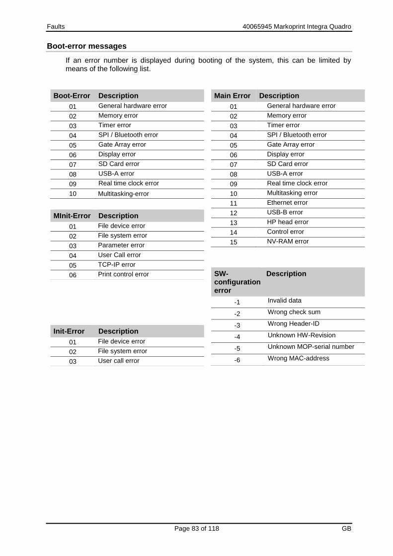
Faults 40065945 Markoprint Integra Quadro
Page 83 of 118 GB
Boot-error messages
If an error number is displayed during booting of the system, this can be limited by means of the following list.
Boot-Error Description
01 General hardware error
02 Memory error
03 Timer error
04 SPI / Bluetooth error
05 Gate Array error
06 Display error
07 SD Card error
08 USB-A error
09 Real time clock error
10 Multitasking-error
Main Error Description
01 General hardware error
02 Memory error
03 Timer error
04 SPI / Bluetooth error
05 Gate Array error
06 Display error
07 SD Card error
08 USB-A error
09 Real time clock error
10 Multitasking error
11 Ethernet error
12 USB-B error
13 HP head error
14 Control error
15 NV-RAM error
MInit-Error Description
01 File device error
02 File system error
03 Parameter error
04 User Call error
05 TCP-IP error
06 Print control error
Init-Error Description
01 File device error
02 File system error
03 User call error
SW-configuration error
Description
-1 Invalid data
-2 Wrong check sum
-3 Wrong Header-ID
-4 Unknown HW-Revision
-5 Unknown MOP-serial number
-6 Wrong MAC-address

Faults 40065945 Markoprint Integra Quadro
Page 84 of 118 GB
Boot-LED messages
During booting of the system progress can be determined by means of the LED. If the system stops during booting the cause can be determined by means of the LED. FC means flashing. An error can be determined on the basis of the number of flashes.
Status-LED
Fehler! Es ist nicht möglich,
durch die Bearbeitung
von Feldfunktionen
Objekte zu erstellen.
Sensor-LED
Description
ye ye Write 64MB memory
rd — Read/ invert 64MB memory
— rd Read/ test 64MB memory
ye — Test ok / Load BootMain from SPI
— ye Programming and start of BootMain
ye rd BootMain initialization
— — Fatal error
rd rd Boot error 4x = SPI; 5x = GA; 6x = Displ; 7x = SD-Card; 8x = USB; 9x = RTC; 10x = Task
rd FC: rd Init error 1x = Dev; 2x = FS; 3x= UsrCl
rd FC: gn SD card read
ye gn Wait for stick
ye rd / gn No boot data
ye rd / — Write 64MB memory
ye ye / gn Booting from stick?
ye ye / rd Copy from stick?
ye gn / — Copy Ok
gn — Main program loaded and started

Disassembly 40065945 Markoprint Integra Quadro
Page 85 of 118 GB
Disassembly
When end of the useful life expires, the system must be disassembled and disposed in an environmentally-friendly manner.
Safety
Staff
Danger to life through electric shock!
DANGER TO LIFE!
Contact with live parts poses imminent danger to life. Damaged insulation or individual components can be lethal.
Therefore:
– Immediately switch off the power supply and initiate repairs if the insulation is damaged.
– Work on the electrical system may only be performed by electricians.
– Before working on the electrical system, disconnect from the mains (remove mains plug) and check that power is off.
– Always disconnect mains before performing cleaning and repair tasks.
– Keep moisture from live parts. Moisture may cause a short-circuit.
Risk of injury caused by improper disassembly!
WARNING!
Stored residual energy, sharp-edged components, points and corners on and inside the apparatus or on the required tools may cause injuries.
Therefore:
– Ensure adequate space before starting any work.
– Handle exposed sharp-edged components with care.
– Keep the work area clean and tidy! Loosely stacked or scattered components and tools are potential causes of accidents.
– Secure components to prevent falling down or falling over.
– Consult the manufacturer if uncertain.

Disassembly 40065945 Markoprint Integra Quadro
Page 86 of 118 GB
Disassembly may only be performed by specially trained specialized staff.
Work on the electrical system may only be performed by electricians.
Disposal
Environmental damage due to incorrect disposal!
Electrical scrap, electronic components, lubricants and other auxiliary materials are subject to hazardous waste treatment regulations and may only be disposed of by approved specialized companies!
Unless return or disposal agreements were made, submit disassembled components for recycling:
Scrap metals.
Submit plastic components for recycling.
Dispose of other components according to material composition. The local municipal authorities or specialized disposal companies provide information on environmentally compatible disposal.

List of accessories and spare parts 40065945 Markoprint Integra Quadro
Page 87 of 118 GB
List of accessories and spare parts
Safety hazard due to incorrect spare parts!
Incorrect or faulty spare parts may affect safety and cause damage, malfunctions or failure.
Therefore:
– Only use original spare parts from the manufacturer.
Procure spare parts via contracted dealers or directly from the manufacturer.
Mounting brackets
No. Figure Article Description Order no.
1
Mounting bracket controller MX print head
For a fixing on a conveyor from the side.
71800027
2
Mounting bracket HP print head
For a fixing on a conveyor from the side, with quick fastener to take the head out of the mounting bracket without technical tools. Model „Dovetail“
72801010
3
Mounting bracket HP print head TOP
For a fixing on a conveyor from the top, with quick fastener to take the head out of the mounting bracket without technical tools. Model „Dovetail“
72801011
4
Mounting bracket MX print head TOP
For a fixing on a conveyor from the top.
71800029
5
Floor stand for 1 or 2 print heads
For a fixing on a conveyor from the top.
71800034

List of accessories and spare parts 40065945 Markoprint Integra Quadro
Page 88 of 118 GB
Other
No. Figure Subassembly Description Order no.
1
Light barrier NPN, 10…30V DC Standard M18
including 5.0 m connecting and adapter cable (M12 to M8) and universal holder
72801012
2
Light barrier NPN, 10…30V DC M8
including 0.6 m connecting cable and VA holder, for direct mounting of the print head from the side
72801013
3
Light barrier NPN, 10…30V DC, external 32x15mm
for mounting behind the front panel, including 0.6 m connecting cable
72801014
4
Sensor (NPN), 10-30V DC, Integra Quadro MX
Including. 5,0m connecting cable (M8 to M8) and bracket for print head mounting
72801074
5
Sensor (NPN), 10-30V DC, Integra Quadro with protection plate
Including 5,0m connecting cable (M8 to M8) and protection plate for MX 50
72801077
6
Sensor (NPN), 10-30V DC, Integra Quadro with protection plate
Including 5,0m connecting cable (M8 to M8) and protection plate for MX 100
72801079
7
Rotary encoder (600dpi) Spring arm holder
Rotary encoder with spring arm and aluminium friction wheel (600dpi), including connecting and adapter cable (M12 to M8)
72801018
8
Rotary encoder Spring arm holder
Rotary encoder with spring arm and plastic friction wheel, including connecting and adapter cable (M12 to M8)
72801018

Operation 40065945 Markoprint Integra Quadro
Page 89 of 118 GB
No. Figure Subassembly Description Order no.
9
Rotary encoder (600dpi) Angle holder
Rotary encoder with angle holder and aluminium friction wheel (600dpi), including connecting and adapter cable (M12 to M8)
72801019
10
Rotary encoder Angle holder
Rotary encoder with angle holder and plastic friction wheel, including connecting and adapter cable (M12 to M8)
72801016
11
USB-data-stick Version 1 72901202
12 CartClip for retaining ink cartridges type 15/45
72900074
13 Ink-Aktivator for de-aerating and cleaning the ink cartridges
72900108
14 CartClip for retaining LX ink cartridges 72902026
15 Fehler! Es ist nicht möglich, durch die Bearbeitung von Feldfunktionen
Objekte zu erstellen.
Measuring wheel Measuring wheel for encoder, optimized for 600 dpi
72900454
16
O-Ring O-ring for encoder measuring wheel (600 dpi) Dimensions: 55x5; NBR
72900455
17
Alarm light „Alarm light“ (red/yellow/green) for an optical display of the operation
22702287
18 Cable Connecting cable 1m 72900225
19 Cable Connecting cable 3m Standard accessories with every print head
72900053
20 Cable Connecting cable 5m 72900085
21 Cable Connecting cable 10m 72900226
22 Cable Connecting cable 25m 72900228

Operation 40065945 Markoprint Integra Quadro
Page 90 of 118 GB
No. Figure Subassembly Description Order no.
23 Cable Extension cable 5m 72900086
24 Cable Extension cable 10m 72900227
25 Cable Adapter M8 connector to M12 socket 0,6m
72901035
26
Cleaning stick Cleaning stick to clean the nozzle plate
40007189

Appendix 40065945 Markoprint Integra Quadro
Page 91 of 118 GB
Appendix
Save parameter to a label
There is the possibility to save parameter settings to a desired print label. The function is advantageous if frequently changing products should be print and these have different measurements and print positions. The menu item is in the control system available if the function „Save parameter“ is activated by iDesign software.
Requirements
The control system is connected via Ethernet or USB with a PC, on which the iDesign software is installed. Instruction Please activate the function „Save parameter“ in the iDesign software as follows:
Step Procedure
1 Activate the function „Save parameter to a label“ in the iDesign software below Functions -> System settings -> Advanced settings.
After the function „Save parameter“ is activated in the iDesign software, select the menu item „Save parameter“ in the menu structure of the control system.
If a print label with saved parameter is selected, the saved parameter will be used. If a print label without saved parameter is selected, the last settings will be used. After changes were made to the parameter, this can saved to the print label, as described below. The next time the print label is selected, it will be print with the saved parameter.
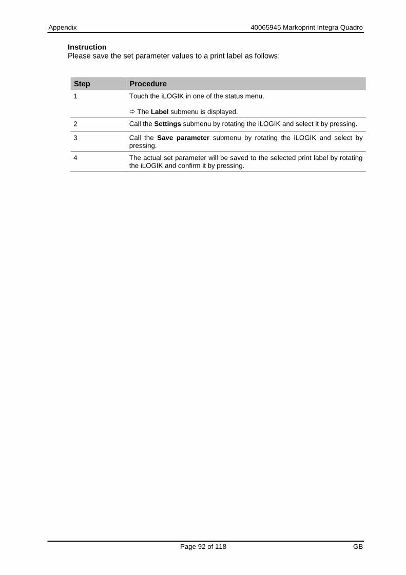
Appendix 40065945 Markoprint Integra Quadro
Page 92 of 118 GB
Instruction Please save the set parameter values to a print label as follows:
Step Procedure
1 Touch the iLOGIK in one of the status menu. The Label submenu is displayed.
2 Call the Settings submenu by rotating the iLOGIK and select it by pressing.
3 Call the Save parameter submenu by rotating the iLOGIK and select by pressing.
4 The actual set parameter will be saved to the selected print label by rotating the iLOGIK and confirm it by pressing.

Appendix 40065945 Markoprint Integra Quadro
Page 93 of 118 GB
Ink chart
The Markoprint Integra Quadro has a deposit ink chart. From this one the optimal parameters are taken over for the selected ink automatically. If the parameters were changed in the iDesign software, the changed parameters stay active till a new ink type will be select on the Markoprint Integra Quadro. Die Tinten-Tabelle ist im HMI Verzeichnis als Excel Tabelle abgelegt: „InkPar.csv“. The ink chart is discarded in the HMI index as excel sheet: “InkPar.csv“. The chart can be adapted customized with an HMI update and can transferred to the Markoprint Integra Quadro.
Changes of the ink parameter can cause bad print images.
„InkPar.csv“ (for HP systems):
„InkParLX.csv“ (for LX systems):
„InkParMX.csv“ (for MX systems):
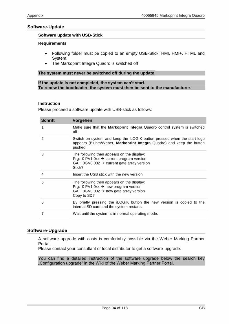
Appendix 40065945 Markoprint Integra Quadro
Page 94 of 118 GB
Software-Update
Software update with USB-Stick
Requirements
Following folder must be copied to an empty USB-Stick: HMI, HMI+, HTML and System.
The Markoprint Integra Quadro is switched off
The system must never be switched off during the update. If the update is not completed, the system can’t start. To renew the bootloader, the system must then be sent to the manufacturer.
Instruction
Please proceed a software update with USB-stick as follows:
Schritt Vorgehen
1 Make sure that the Markoprint Integra Quadro control system is switched off.
2 Switch on system and keep the iLOGIK button pressed when the start logo appears (Bluhm/Weber, Markoprint Integra Quadro) and keep the button pushed.
3 The following then appears on the display: Prg: 0 PV1.0xx current program version GA.: 0GV0.032 current gate array version Stick?
4 Insert the USB stick with the new version
5 The following then appears on the display: Prg: 0 PV1.0xx new program version GA.: 0GV0.032 new gate array version Copy to SD?
6 By briefly pressing the iLOGIK button the new version is copied to the internal SD card and the system restarts.
7 Wait until the system is in normal operating mode.
Software-Upgrade
A software upgrade with costs is comfortably possible via the Weber Marking Partner Portal. Please contact your consultant or local distributor to get a software-upgrade. You can find a detailed instruction of the software upgrade below the search key „Configuration upgrade“ in the Wiki of the Weber Marking Partner Portal.

Appendix 40065945 Markoprint Integra Quadro
Page 95 of 118 GB
USB-Stick files
Following files are saved on the USB-stick:
iDesign-Software
Manual Markoprint Integra Quadro
Manual iDesign Software
Leaflet The required files for software updates:
HMI-directory
HMI+ -directory
HTML-directory
System-directory
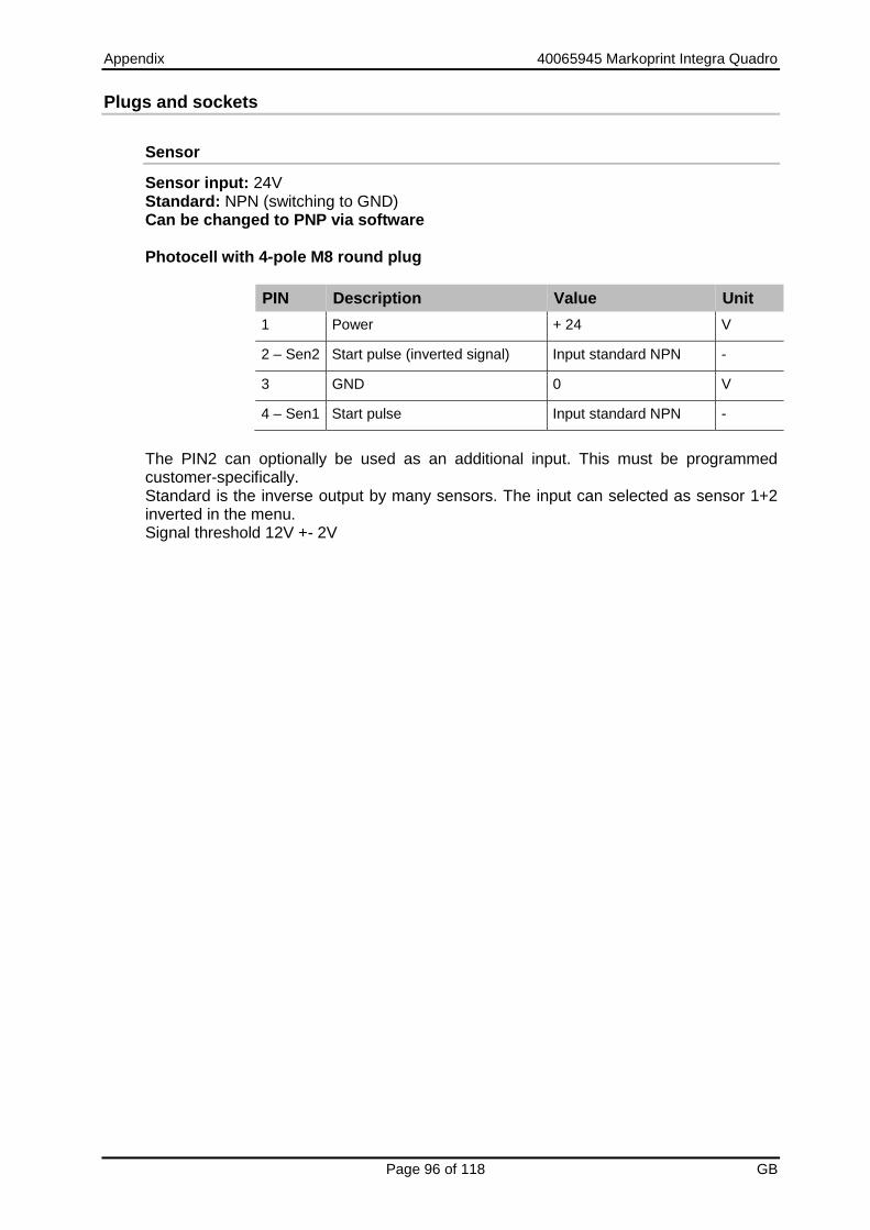
Appendix 40065945 Markoprint Integra Quadro
Page 96 of 118 GB
Plugs and sockets
Sensor
Sensor input: 24V Standard: NPN (switching to GND) Can be changed to PNP via software Photocell with 4-pole M8 round plug
PIN Description Value Unit
1 Power + 24 V
2 – Sen2 Start pulse (inverted signal) Input standard NPN -
3 GND 0 V
4 – Sen1 Start pulse Input standard NPN -
The PIN2 can optionally be used as an additional input. This must be programmed customer-specifically. Standard is the inverse output by many sensors. The input can selected as sensor 1+2 inverted in the menu. Signal threshold 12V +- 2V

Operation 40065945 Markoprint Integra Quadro
Page 97 of 118 GB
Encoder
Encoder input: 24V Standard: NPN or push-pull max. 100 kHz Rotary encoder with 4-pole M8 round plug
PIN Description Value Unit
1 Power, max. 10mA + 24 V
2
3 GND 0 V
4 Encoder signal Standard: NPN or push-pull
-
If using a PNP encoder or a PNP Signal as encoder the encoder input must be pulled to GND with an 1KOhm resistor. The resistor must be for min.1W and the load is about 25mA.
Cable colours
PIN Cable colour
1 Brown 24V
2 White input
3 Blue 0V (ground)
6 Black input
When using the splitter cable are both inputs / outputs clearly separated. The output is on a socket on PIN4 (siehe Fehler! Verweisquelle konnte nicht gefunden werden.).
PIN 1 BN (brown)
PIN 2 WH (white) PIN 4 BK (black)
PIN 3 BU (blue)
View on plug back side
Fig. 15: Socket 4-pole M8 plug

Operation 40065945 Markoprint Integra Quadro
Page 98 of 118 GB
Fig. 16: Splitter cable and whose pin assignment
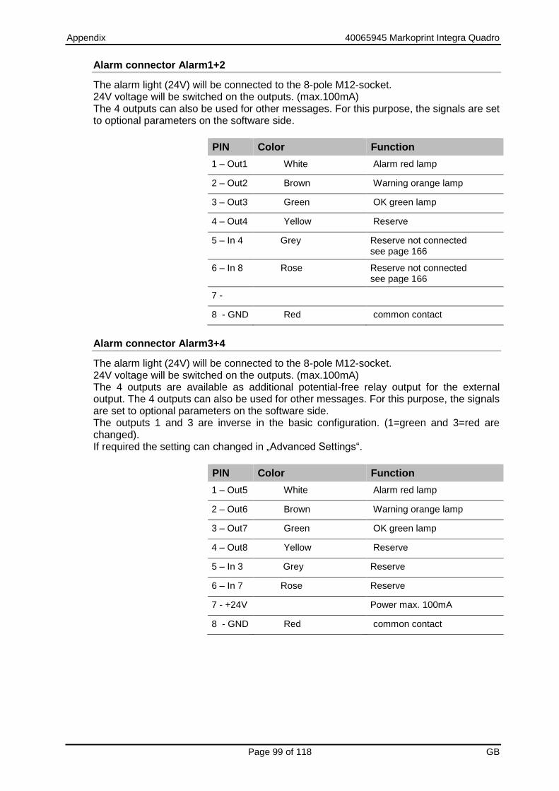
Appendix 40065945 Markoprint Integra Quadro
Page 99 of 118 GB
Alarm connector Alarm1+2
The alarm light (24V) will be connected to the 8-pole M12-socket. 24V voltage will be switched on the outputs. (max.100mA) The 4 outputs can also be used for other messages. For this purpose, the signals are set to optional parameters on the software side.
PIN Color Function
1 – Out1 White Alarm red lamp
2 – Out2 Brown Warning orange lamp
3 – Out3 Green OK green lamp
4 – Out4 Yellow Reserve
5 – In 4 Grey Reserve not connected see page 166
6 – In 8 Rose Reserve not connected see page 166
7 -
8 - GND Red common contact
Alarm connector Alarm3+4
The alarm light (24V) will be connected to the 8-pole M12-socket. 24V voltage will be switched on the outputs. (max.100mA) The 4 outputs are available as additional potential-free relay output for the external output. The 4 outputs can also be used for other messages. For this purpose, the signals are set to optional parameters on the software side. The outputs 1 and 3 are inverse in the basic configuration. (1=green and 3=red are changed). If required the setting can changed in „Advanced Settings“.
PIN Color Function
1 – Out5 White Alarm red lamp
2 – Out6 Brown Warning orange lamp
3 – Out7 Green OK green lamp
4 – Out8 Yellow Reserve
5 – In 3 Grey Reserve
6 – In 7 Rose Reserve
7 - +24V Power max. 100mA
8 - GND Red common contact

Appendix 40065945 Markoprint Integra Quadro
Page 100 of 118 GB
External Output
The outputs are potential-free. The relay is designed for 24V. Relay output: max 24 V and max. 100 mA. Standard: Closing contact.
Connection 15-pole Sub-D-socket.
Input NPN input, can be changed to PNP via software.
Standard NPN (to GND switching)
Input voltage for PNP 10 V…24 V
PIN Name Beschreibung Potenzial
1 Out 5 Relay 1 OK
2 Out 5 Relay 1
3 Out 6 Relay 2 Warn
4 Out 6 Relay 2
5 Out 7 Relay 3 Alarm
6 Out 7 Relay 3
7 Out 8 Relay 4 Reserve
8 Out 8 Relay 4
9 max.100 mA
24V internal +24 V
10 GND 0 V
11 In 1 Input 1
12 In 2 Input 2
13 In 5 Input 5
14 In 6 Input 6
15 NC

Appendix 40065945 Markoprint Integra Quadro
Page 101 of 118 GB
Inputs 1, 2, 5 and 6 on 15-pin SubD plug with examples
By default, the standard wiring is NPN. Inputs 1-4 and inputs 5-8 can be set to PNP as groups, software-side.
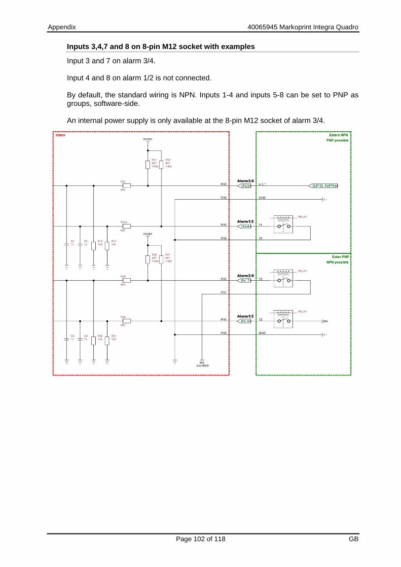
Appendix 40065945 Markoprint Integra Quadro
Page 102 of 118 GB
Inputs 3,4,7 and 8 on 8-pin M12 socket with examples
Input 3 and 7 on alarm 3/4. Input 4 and 8 on alarm 1/2 is not connected. By default, the standard wiring is NPN. Inputs 1-4 and inputs 5-8 can be set to PNP as groups, software-side. An internal power supply is only available at the 8-pin M12 socket of alarm 3/4.

Appendix 40065945 Markoprint Integra Quadro
Page 103 of 118 GB
Outputs 5-8 on 15-pin SubD socket with examples
The outputs 5-8 can be supplied externally (potential-free) and internally with voltage.

Appendix 40065945 Markoprint Integra Quadro
Page 104 of 118 GB
Encoder 1/2 and Encoder 3/4 on 4-pin M8 plug with example

Appendix 40065945 Markoprint Integra Quadro
Page 105 of 118 GB
Sensor 1/2 and Sensor 3/4 on 4-pin M8 plug with example
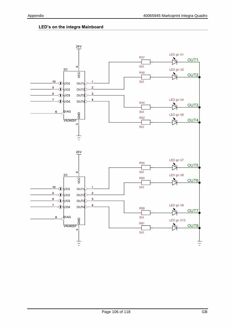
Appendix 40065945 Markoprint Integra Quadro
Page 106 of 118 GB
LED’s on the integra Mainboard

Appendix 40065945 Markoprint Integra Quadro
Page 107 of 118 GB

Appendix 40065945 Markoprint Integra Quadro
Page 108 of 118 GB

Appendix 40065945 Markoprint Integra Quadro
Page 109 of 118 GB
Outputs IN4 and IN8 connecting on the flange plate: On the mainboard you can find a connector with IN4 and IN8:
These three pins must be connected with the M12 connector to reach the signals from the outside.
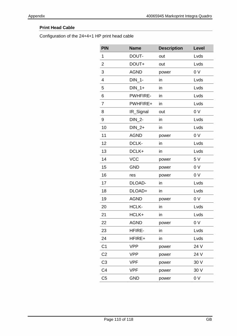
Appendix 40065945 Markoprint Integra Quadro
Page 110 of 118 GB
Print Head Cable
Configuration of the 24+4+1 HP print head cable
PIN Name Description Level
1 DOUT- out Lvds
2 DOUT+ out Lvds
3 AGND power 0 V
4 DIN_1- in Lvds
5 DIN_1+ in Lvds
6 PWHFIRE- in Lvds
7 PWHFIRE+ in Lvds
8 IR_Signal out 0 V
9 DIN_2- in Lvds
10 DIN_2+ in Lvds
11 AGND power 0 V
12 DCLK- in Lvds
13 DCLK+ in Lvds
14 VCC power 5 V
15 GND power 0 V
16 res power 0 V
17 DLOAD- in Lvds
18 DLOAD+ in Lvds
19 AGND power 0 V
20 HCLK- in Lvds
21 HCLK+ in Lvds
22 AGND power 0 V
23 HFIRE- in Lvds
24 HFIRE+ in Lvds
C1 VPP power 24 V
C2 VPP power 24 V
C3 VPF power 30 V
C4 VPF power 30 V
C5 GND power 0 V
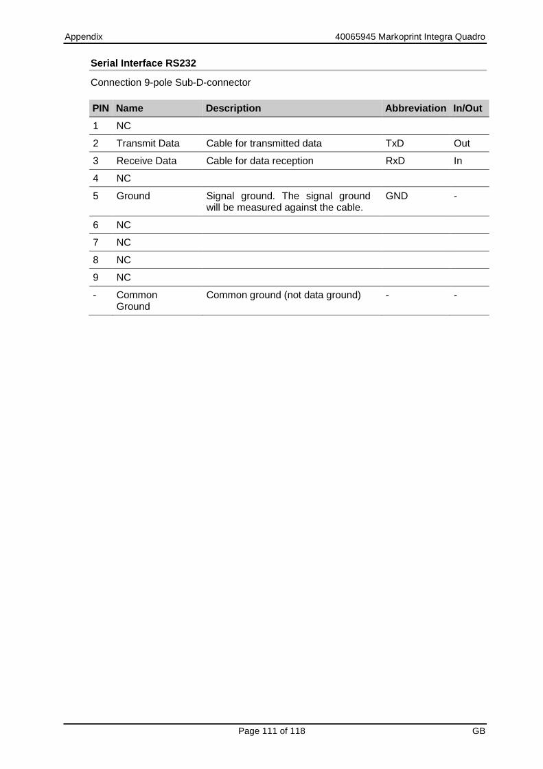
Appendix 40065945 Markoprint Integra Quadro
Page 111 of 118 GB
Serial Interface RS232
Connection 9-pole Sub-D-connector
PIN Name Description Abbreviation In/Out
1 NC
2 Transmit Data Cable for transmitted data TxD Out
3 Receive Data Cable for data reception RxD In
4 NC
5 Ground Signal ground. The signal ground will be measured against the cable.
GND -
6 NC
7 NC
8 NC
9 NC
- Common Ground
Common ground (not data ground) - -

Appendix 40065945 Markoprint Integra Quadro
Page 112 of 118 GB
USB A / B
The USB sockets are standard sockets, as used in commercial PCs and USB devices. Insert the USB plug vertically into the USB socket without using force.
PIN Name Colour Description
1 VCC Red +5 V
2 D- White Data -
3 D+ Green Data +
4 GND Black Mass
Ethernet
Connection Network input RJ 45
PIN Description
1 Transmit+
2 Transmit-
3 Receive+
6 Receive-
Mac addresses
The MAC address of the respective Markoprint Integra Quadro an be seen on the system directly. Chapter Gate-Way and MAC address, page 71
Range from: To:
00-50-C2-A6-50-00 00-50-C2-A6-5F-FF
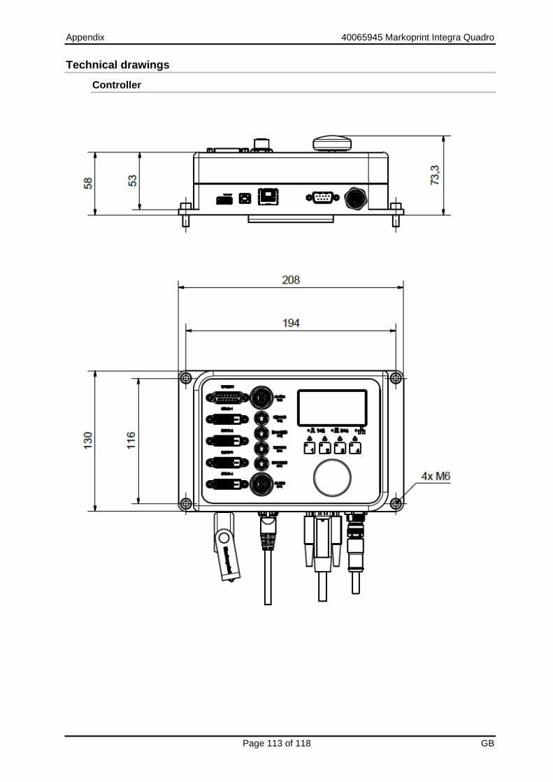
Appendix 40065945 Markoprint Integra Quadro
Page 113 of 118 GB
Technical drawings
Controller

Operation 40065945 Markoprint Integra Quadro
Page 114 of 118 GB

Appendix 40065945 Markoprint Integra Quadro
Page 115 of 118 GB
Instruction sheet
Copy the instruction sheet before completing.
Date Name Type of instruction Instruction by Signature

Appendix 40065945 Markoprint Integra Quadro
Page 116 of 118 GB
Parameter list
Parameter After Reset Min. Max. Actual value
Unit
Pulse Internal Head2 from head 1
Speed 15,0 1,0 400 m/min
Encoder 600 50 5000 ppi
Print direction
RL LR RL
Upside down
No No Yes
Reflect Not used
Print delay 25 0 999 mm
Print repeat distance
0 0 9999 mm
Number of print repeats:
0 0 999
Intensity 50 300 900 DPI
Print width 100 10 900 %
Nozzle rows A~B A,B A+B
Head voltage
110 V
Fire time 190 0,01µs
Fire pause 190 0,01µs
Barcode correction
0 Pixel
Ink warning 5 0 100 %
Spitting mode
OFF BEFORE INTERVALL
Number of spit ripping
20 0 100
Spit delay 10 0 999 s
Spit interval 600 0 999 s
Auto Off 60 0 999 min.
Head correction
0 -50 +50 Pixel
Offset bi directional
0 -20 +20
Warming OFF OFF ON
Warming Temp.
45 20 80 °C

Operation 40065945 Markoprint Integra Quadro
Page 117 of 118 GB
Parameter After Reset Min. Max. Actual value
Unit
Warming timer 0 0 999 s
Counter start value Not used
Language German -
Head type 1111 1000 4000
Ink type STABL -
User 1 Not used -
User 2 Not used
User 3 Not used
Print mode Not used
Save variable fields
Not used
Sensor 1+2 1+2 3+4
Turning display Not used
Sensor I/O Not used
Encoder I/O Not used
Trigger output delay
Not used
Impulse length output
Not used
HiSpeed NO YES NO
Fixed print width YES NO YES
EIA232 Not used
Polarity input 0000
Input 1,2 0000
Input 3,4 0000
Input 5,6 0000
Input 7,8 0000
Output 1,2 3020
Output 3,4 1000
Output 5,6 1020
Output 7,8 3000

Appendix 40065945 Markoprint Integra Quadro
Page 118 of 118 GB
The Markoprint Integra Quadro will be reseted to the basic configuration after sending these commands.
<ESC>K1<CR> <ESC>M*;0000;0150;0004;0000;0000;0000;0025;0000;0000;0300;0100;0000;0110;0190;0190;0000;0005;0000;0020;0010;0600;0060;0000;0000;0000;0045;0000;0000;0000;1111;0001;0000;0000;0000;0000;0000;0000;0000;0000;0000;0000;0000;0000;0000;0000;0000;0000;0000;0000;0000;3020;1000;1020;3000<CR> <ESC>K2<CR> <ESC>M*;0000;0150;0004;0000;0000;0000;0025;0000;0000;0300;0100;0000;0110;0190;0190;0000;0005;0000;0020;0010;0600;0060;0000;0000;0000;0045;0000;0000;0000;1111;0001;0000;0000;0000;0000;0000;0000;0000;0000;0000;0000;0000;0000;0000;0000;0000;0000;0000;0000;0000;3020;1000;1020;3000<CR> <ESC>K3<CR> <ESC>M*;0002;0150;0004;0000;0000;0000;0025;0000;0000;0300;0100;0000;0110;0190;0190;0000;0005;0000;0020;0010;0600;0060;0000;0000;0000;0045;0000;0000;0000;1111;0001;0000;0000;0000;0000;0000;0000;0000;0000;0000;0000;0000;0000;0000;0000;0000;0000;0000;0000;0000;3020;1000;1020;3000<CR> <ESC>K4<CR> <ESC>M*;0002;0150;0004;0000;0000;0000;0025;0000;0000;0300;0100;0000;0110;0190;0190;0000;0005;0000;0020;0010;0600;0060;0000;0000;0000;0045;0000;0000;0000;1111;0001;0000;0000;0000;0000;0000;0000;0000;0000;0000;0000;0000;0000;0000;0000;0000;0000;0000;0000;0000;3020;1000;1020;3000<CR>