Embed Size (px)
Citation preview

KARDAN MİLİ
TAHRİK MİLİ ve
MAFSALLAR
Yrd. Doç. Dr. Abdullah DEMİR
HAZIRLAYAN:
Yrd. Doç. Dr. Abdullah DEMİR
MARMARA ÜNİVERSİTESİ TEKNOLOJİ FAKÜLTESİ

KARDAN MİLİ

FRONT WHEEL DRIVE
http://www.procarcare.com/includes/content/resourcecenter/encyclopedia/ch22/22Fig8.html

REAR WHEEL DRIVE

FOUR-WHEEL DRIVE

ALL-WHEEL DRIVE
KARDAN MİLİ
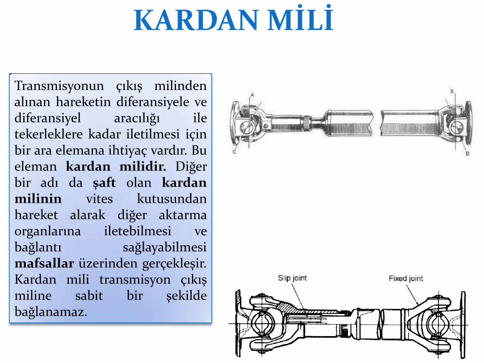
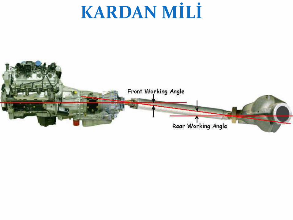
Transmisyonun çıkış milinden alınan hareketin diferansiyele ve diferansiyel aracılığı ile tekerleklere kadar iletilmesi için bir ara elemana ihtiyaç vardır. Bu eleman kardan milidir. Diğer bir adı da şaft olan kardan milinin vites kutusundan hareket alarak diğer aktarma organlarına iletebilmesi ve bağlantı sağlayabilmesi mafsallar üzerinden gerçekleşir. Kardan mili transmisyon çıkış miline sabit bir şekilde bağlanamaz.

Drive Shaft Purposes
Automotive Technology, Nelson, Prepared by Martin Restoule Algonquin College, 2007
Görevleri: Hareketi vites kutusundan
diferansiyel iletir Vites kutusu ile arka köprünün
farklı yüksekliklerde konuşlandırılabilmesine imkan sağlar
Arka aksın yukarı aşağı hareket etmesini sağlar
• Transmits power from the transmission to the differential
• Allows the transmission and the rear axle assembly to be at different heights
• Allows the rear axle to move up and down while maintaining a connection to the transmission

KARDAN MİLİ
Şaftlar genellikle içleri boş millerden imal edilirler. İçi boş olarak yapılan şaftların dayanımı artmakta ve hafiflemektedir. Şaftlar kaliteli çeliklerden yapılırlar, ucuna mafsal çatalları kaynakla bağlanmıştır.
Can be made of steel, aluminum, or composite material

KARDAN MİLİ
Ref.: James E. Duffy, Modern Automotive Tech. - Drive Shaft and Transfer Case Technology

KARDAN MİLİ
Ref.: James E. Duffy, Modern Automotive Tech. - Drive Shaft and Transfer Case Technology

KARDAN MİLİ Burulma ve titreşimlere karşı kauçuk damperli takozlarla takviye edilirler. Titreşimlerden etkilenmemesi ve yüksek devirlerde dönen şaftın merkezkaç kuvvetlere karşı koyabilmesi için çok iyi dengelenmiş olmaları gerekir. Bazı şaftların üzerindeki kaynakla bağlanmış parçacıklar, denge ağırlıklarıdır.

KARDAN MİLİ
Drive Shaft Balance • Drive shaft must be perfectly balanced,
with its weight evenly distributed around its centerline
• Drive shaft balancing weights –Welded to shaft to reduce vibration
• Drive shaft vibration damper –Large, ring shaped weight mounted on rubber –Helps keep shaft spinning smoothly by absorbing torsional vibration
Ref.: James E. Duffy, Modern Automotive Tech. - Drive Shaft and Transfer Case Technology

KARDAN MİLİ
KARDAN MİLİ

KARDAN MİLİ

KARDAN MİLİ
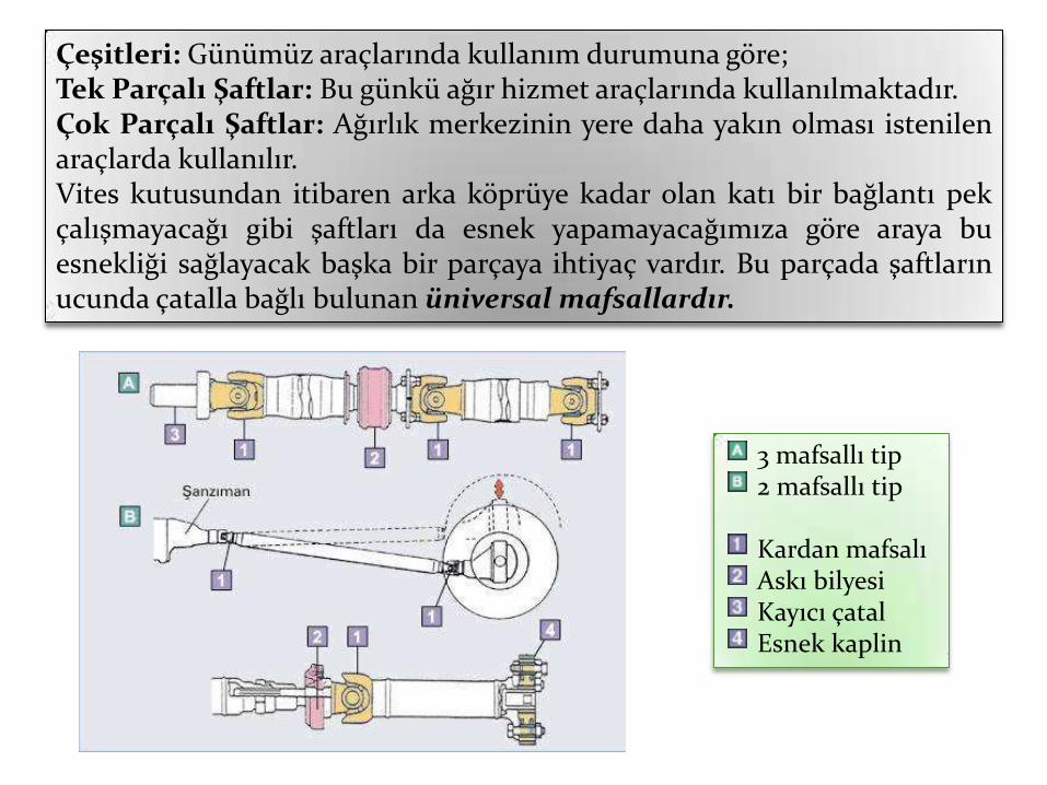
mafsallı tip mafsallı tip
Kardan mafsalı Askı bilyesi Kayıcı çatal Esnek kaplin
Çeşitleri: Günümüz araçlarında kullanım durumuna göre; Tek Parçalı Şaftlar: Bu günkü ağır hizmet araçlarında kullanılmaktadır. Çok Parçalı Şaftlar: Ağırlık merkezinin yere daha yakın olması istenilen araçlarda kullanılır. Vites kutusundan itibaren arka köprüye kadar olan katı bir bağlantı pek çalışmayacağı gibi şaftları da esnek yapamayacağımıza göre araya bu esnekliği sağlayacak başka bir parçaya ihtiyaç vardır. Bu parçada şaftların ucunda çatalla bağlı bulunan “niversal mafsallardır.
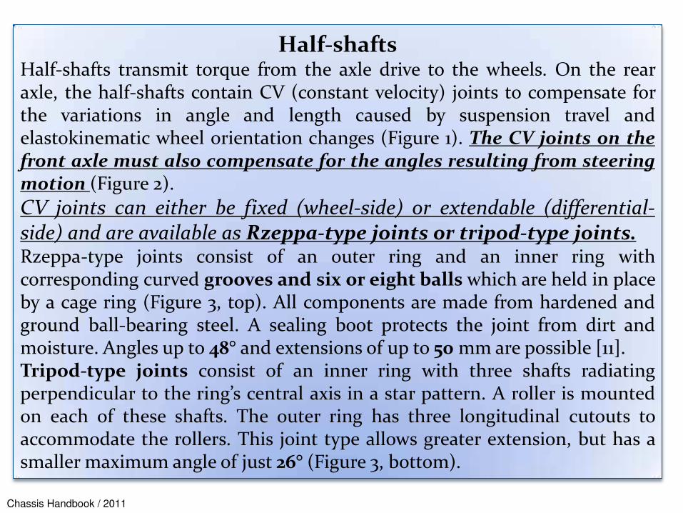
Half-shafts Half-shafts transmit torque from the axle drive to the wheels. On the rear axle, the half-shafts contain CV (constant velocity) joints to compensate for the variations in angle and length caused by suspension travel and elastokinematic wheel orientation changes (Figure 1). The CV joints on the front axle must also compensate for the angles resulting from steering motion (Figure 2).
CV joints can either be fixed (wheel-side) or extendable (differential-side) and are available as Rzeppa-type joints or tripod-type joints. Rzeppa-type joints consist of an outer ring and an inner ring with corresponding curved grooves and six or eight balls which are held in place by a cage ring (Figure 3, top). All components are made from hardened and ground ball-bearing steel. A sealing boot protects the joint from dirt and moisture. Angles up to 48° and extensions of up to 50 mm are possible [11]. Tripod-type joints consist of an inner ring with three shafts radiating perpendicular to the ring’s central axis in a star pattern. A roller is mounted on each of these shafts. The outer ring has three longitudinal cutouts to accommodate the rollers. This joint type allows greater extension, but has a smaller maximum angle of just 26° (Figure 3, bottom).
Chassis Handbook / 2011

Fig. 1: Half-shafts for a driven rear axle
Fig. 2: Half-shafts for a driven front axle [11] Chassis Handbook / 2011

Fig. 3: Fixed and extendable CV joints (top) and a constant-velocity tripod-type joint (bottom) [11] Chassis Handbook / 2011

MAFSALLAR Üniversal Mafsal: Vites kutusunun çıkış mili ile arka köprü arasında yol şartlarından doğan açıyı karşılamak için üniversal mafsal kullanılır. En çok kullanılanı istavroz tipidir. İstavroz tipi üniversal mafsal bir istavroz ile istavrozun kolları üzerindeki iğne masuralı yataklardan meydana gelir. Masuralı yataklar kardan milinin ve karşılığı olan kayıcı mafsalın üzerindeki yuvalarına sıkı geçerler ve yerlerinde birer tespit segmanı tarafından tutulurlar. Bu şekildeki bir düzenleme ile kayıcı mafsal ve kardan mili çatallarının istavroz üzerinde bir mafsal hareketi yapmalarına imkan verir.
Universal Joint Components • Cross and trunnions
• Seals
• Bearings
• Caps
• Snap rings

Üniversal Mafsallar Çeşitleri Mafsallar kullanım şekillerine ve kullanıldığı durumlarına göre şu şekilde sınıflandırılırlar. Üniversal Mafsallar: Dairesel gelen hareketi açılı olarak iletmekte kullanılır. 1. Adi Tip Üniversal Mafsallar: Şaftlarda ve direksiyon sistemlerinde kullanılır. 2. Sabit Hız Üniversal Mafsalları: Akslarda kullanılır. 3. Rzeppa Sabit Hız Mafsalı: Otomobil gibi hızlı ancak güçsüz araçlarda kullanılır. 4. Bendiks-Weiss Sabit Hız Mafsalı: Otomobilden daha güçlü kamyonetlerde
kullanılır. 5. Tracka Sabit Hız Mafsalı: Güçlü arazi araçları, kamyon ve otobüs vb. araçlarda
kullanılır.
Kardan mafsalı Çatal İstavroz zarfı İstavroz

Fig. Front-wheel output shaft of GKN Automotive. A constant-velocity sliding joint is used on the gearbox side and a constant-velocity fixed joint is used on the wheel side. The maximum bending angles are 22 for the sliding joint and for the fixed joint. For reasons of weight, the sliding joint is placed directly into the differential and fixed axially by a circlip. A central nut secures attachment on the wheel side. The intermediate shaft is designed as a carburized, shaped hollow shaft. / Ref. The Automotive Chassis

Tatsuro Sugiyama,Yuichi Asano, “Lightweight and High-efficiency Drive Shafts for Rear-wheel-drive Cars”, NTN TECHNICAL REVIEW,
Construction of drive shaft for FWD cars

Ref.: James E. Duffy, Modern Automotive Tech. - Drive Shaft and Transfer Case Technology
Constant Velocity Universal Joint

Ref.: James E. Duffy, Modern Automotive Tech. - Drive Shaft and Transfer Case Technology
Center Support Bearing • Center support bearing
–Holds middle of two-piece drive shaft • Center bearing bolts to vehicle’s frame or underbody • Supports center of drive shaft where two shafts come
together

MAFSALLAR
Ref.: James E. Duffy, Modern Automotive Tech. - Drive Shaft and Transfer Case Technology
Cross-and-Roller Universal Joint

MAFSALLAR
Kayıcı Mafsallar: Arkadan itişli seyir sırasında arka aks yoldan gelen etkiler nedeniyle aşağı yukarı hareket eder. Bu durum vites kutusu ile diferansiyel arasındaki mesafeyi sürekli değiştirir. Bu nedenle şafttın boyunun uzaması veya kısalması gereklidir. Ancak şaftlar elastiki bir malzemeden yapılmadıkları için uzama veya kısalma imkânsızdır. Şaftın boyunda yol şartlarına göre değişim olmazsa araç zıplayarak engelleri aşacaktır. Bu durumda da içerdeki yolcu/lar/ rahatsız olacak veya taşınacak malzeme de zarar görebilecektir.

MAFSALLAR
Kayıcı Mafsallar (dvm.) Aracın hareketi esnasında arka köprü bir tümseğe veya bir çukura gelmesi durumunda şaftın boyunda değişim ihtiyacı doğar. Şaftın yapısı nedeniyle boyunun değişmesi mümkün değildir. Boyundaki değişim ihtiyacı kayıcı mafsal yardımıyla sağlanır. Vites kutusu çıkış mili üzerine kamalar açılmıştır. Şaft flanşının iç kısmına da aynı kamlardan açılmıştır. Yol şartları nedeniyle şaftın boyunun değişmesi gerektiğinde, şaft flanşı vites kutusu çıkış mili üzerinde kayarak şaftın boyunun kısalmasını veya uzamasını sağlar.

Ref.: James E. Duffy, Modern Automotive Tech. - Drive Shaft and Transfer Case Technology
• Slip yoke, or slip joint • Splined to transmission
output shaft • Allows for changes in
driveline length by sliding in and out of transmission
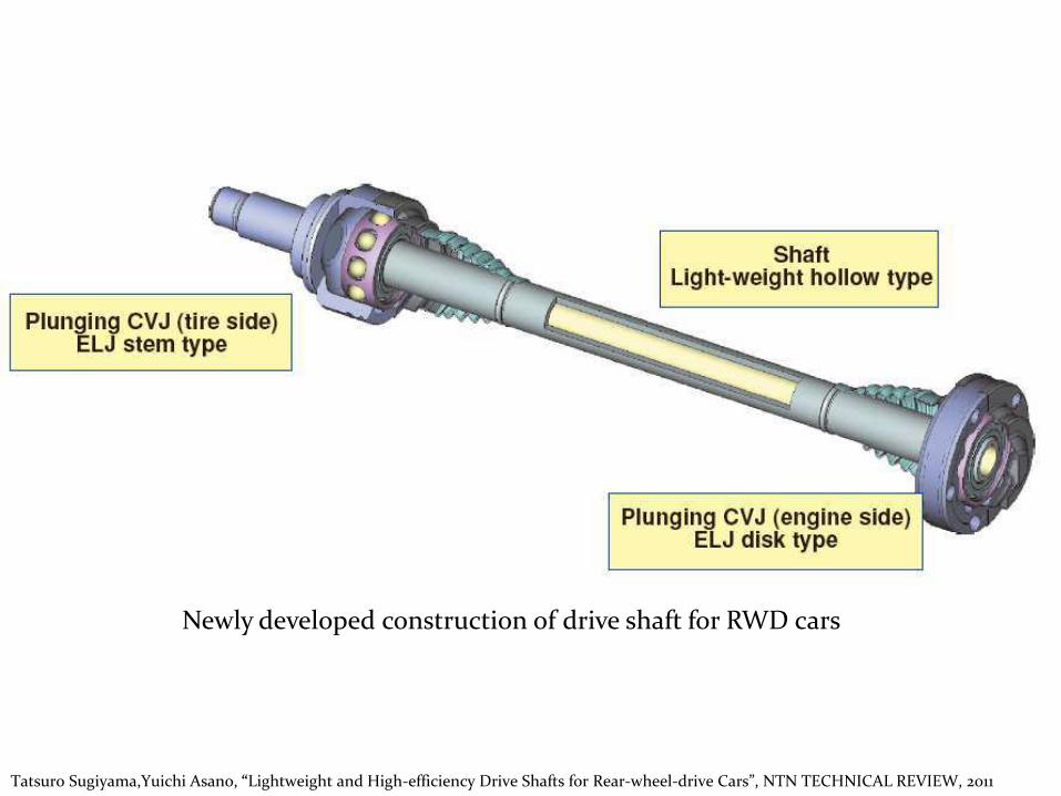
Tatsuro Sugiyama,Yuichi Asano, “Lightweight and High-efficiency Drive Shafts for Rear-wheel-drive Cars”, NTN TECHNICAL REVIEW,
Newly developed construction of drive shaft for RWD cars
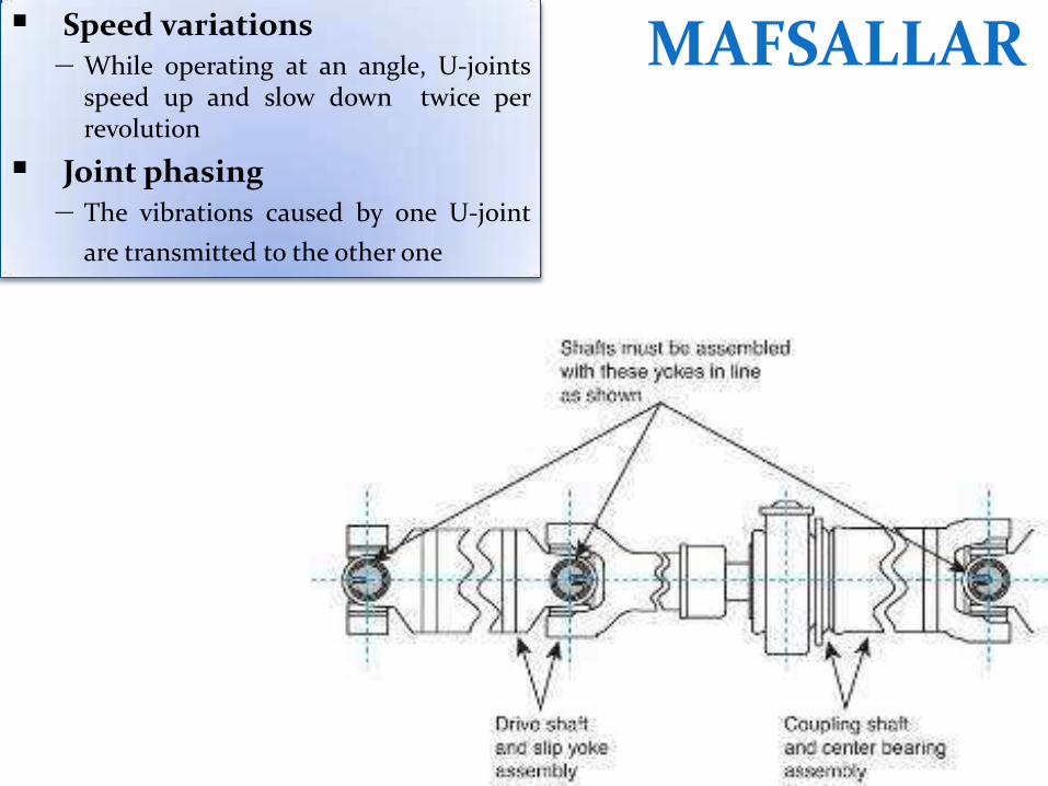
MAFSALLAR Speed variations – While operating at an angle, U-joints
speed up and slow down twice per revolution Joint phasing
– The vibrations caused by one U-joint
are transmitted to the other one

MAFSALLAR Canceling angles – The angle of the front U-joint is offset by
the rear one
– The correct angle must be maintained to
minimize vibration
U-Joint Operation Vibration may be felt if the U-
joint angles are too steep or are unequal.
U-joints must be in phase with each other to reduce noise and vibration.

Automotive Technology, Nelson, Prepared by Martin Restoule Algonquin College, 2007
U-Joint Operation The U-joint normally speeds up and slows down twice per revolution.
MAFSALLAR

MAFSALLAR
Single Hooke’s joint: (a) Geometry (b) Speed fluctuation

MAFSALLAR
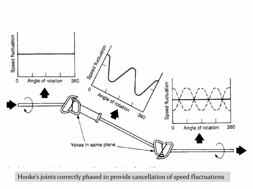
Hooke’s joints correctly phased to provide cancellation of speed fluctuations

Conditions for constant-velocity drive with two Hooke’s joints
Ref.: James E. Duffy, Modern Automotive Tech. - Drive Shaft and Transfer Case Technology
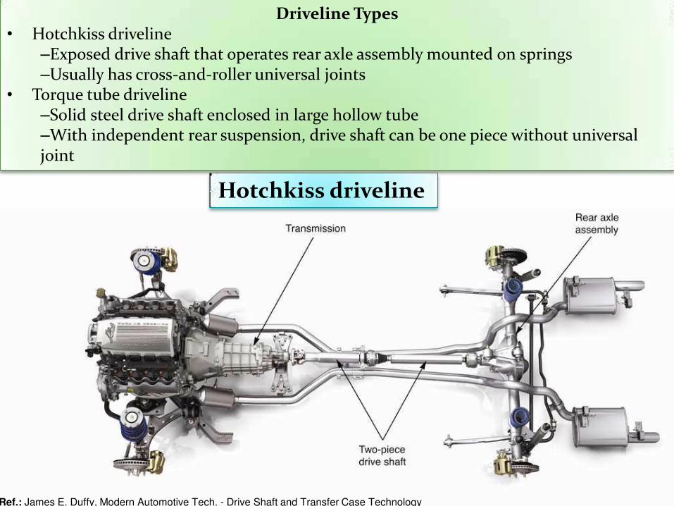
Driveline Types • Hotchkiss driveline
–Exposed drive shaft that operates rear axle assembly mounted on springs –Usually has cross-and-roller universal joints
• Torque tube driveline –Solid steel drive shaft enclosed in large hollow tube –With independent rear suspension, drive shaft can be one piece without universal joint
Hotchkiss driveline

Şaftlarda Hareket İletim Sistemleri Motorun gücü, döndürme momenti biçiminde arka tekerleklere uygulanıp, tekerlek yerin göstermiş olduğu dirence karşı döndürülmeye zorlanınca, Newton Kanunu gereğince, bir karşı tepki görür. Ortaya çıkan reaksiyon torku köprüyü tekerleğin dönüş yönünün tersine döndürmeye çalışır. Bu hareketin sonucu olarak meydana gelen torka arka köpr“ torku denir. Arka köprünün, özellikle diferansiyel muhafazasının bulunduğu bölgenin, oluşan arka köprü torkunun oluşturacağı aşırı hareketlerden korunabilmesi için arka köprü torkunun şasiye faydalı bir şekilde iletilmesi gerekir. Şasiye iletilen bu kuvvet itici olarak aracı yürütür. Arka köprü döndürme torkunun aracın şasisine iletilmesi üç şekilde olur.
1. Hoçkis Sistemi Arka köprü üzerindeki moment yaylar tarafından şasiye iletilirse, bu sisteme Hoçkis sistemi denir. Özellikle yaprak yaylı sistemlerde bu görülür. Yaylar arka köprüye cıvatalarla bağlanmıştır. Yay uçları ise küpelerle şasiyi tutarlar. Kamyon ve kamyonetlerde bu sistem daha yaygın olarak görülür.

Şaftlarda Hareket İletim Sistemleri (dvm)
2. Tork/Moment Kontrol Çubuklu Sistem Arka köprü momenti aracın şasesine ve arka köprüye tespit edilmiş moment kolları aracılığı ile şaseye iletilir. Moment kolları her iki ucundan da cıvatalarla bağlı olmalarına rağmen salınım yapmalarına müsaade edilmiştir. Genellikle bu günkü otomobillerde kullanılan sistemdir.
3. Tork Tüpü Sistemi Arka köprü torkunun şaftı örten bir boruyla şasiye iletildiği sistemdir. Tork tüpü bir ucundan şasiye diğer ucundan ise küresel bir muhafaza ile vites kutusu çıkışına bağlanmıştır. Bir bakıma arka taraf sabit ön taraf ise hareketlidir.

Ekler

MAFSALLAR Universal Joint Are sometimes referred to as Cardan, Spicer, or Hooke joints Allow for angle changes between the drive shaft, the transmission output shaft, and the rear axle housing

MAFSALLAR Universal Joint Designs
• Single universal joint – Sometimes known as single
Cardan/Spicer Universal joint
– Consists of a cross and four needle bearings
• Double Cardan joint – Consists of two single U-joints
joined by a center yoke and a ball
and socket

MAFSALLAR Universal Joint Designs • Slip joint
– Allows for changes in driveshaft length caused by suspension travel
– Components include:
• Transmission output shaft
• The slip joint
• A yoke and U-joint
• The driveshaft

Automotive Technology, Nelson, Prepared by Martin
Restoule Algonquin College, 2007
CV Joint Types Outer joint types
Rzeppa or fixed ball joint
Fixed tripod joint
Inner joint types Double-offset joint
Plunging tripod joint
Cross-groove plunge joint

Axle drive systems for four-wheel platforms in standard vehicle architecture With this concept in vehicles in which the engine is arranged in the longitudinal direction, the transfer box distributes the power to the axle drives from where the power is transferred to the wheels. ZF supplies axle drive systems consisting of the front and rear axle drive units and, where required, the associated CV and prop-shafts. Optionally, an electromechanically locked rear axle drive unit or the VECTOR DRIVE® can be employed. With modern vehicles in this category, the axle drives must satisfy very high performance and quality demands, whilst being optimised for weight and compact packaging. These are the normal demands on a tailor-made axle drive solution from ZF.
ZF - Driving Dynamics

Axle drive systems for four-wheel platforms with front transverse architecture The engine transmission unit arranged transversly above the front axle lends its name to this design. The four-wheel variant is usually derived from a front-wheel drive basic vehicle and includes the additional items of power take-off, rear axle drive unit, prop-shaft and CV-shafts. Within these systems, one can differentiate between variants with a central differential, i.e. Permanent four-wheel drive, and in the meantime dominating versions with a controlled variable coupling which is usually fitted to the rear axle drive unit (torque on demand). The assemblies and system modules developed by ZF are closely orientated to customer requirements and matched to the specific demands of the relevant application. At the same time, the typical product features of ZF axle drives are maintained.
ZF - Driving Dynamics
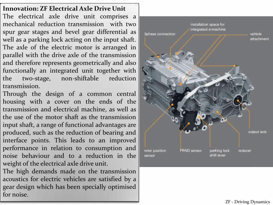
Innovation: ZF Electrical Axle Drive Unit The electrical axle drive unit comprises a mechanical reduction transmission with two spur gear stages and bevel gear differential as well as a parking lock acting on the input shaft. The axle of the electric motor is arranged in parallel with the drive axle of the transmission and therefore represents geometrically and also functionally an integrated unit together with the two-stage, non-shiftable reduction transmission. Through the design of a common central housing with a cover on the ends of the transmission and electrical machine, as well as the use of the motor shaft as the transmission input shaft, a range of functional advantages are produced, such as the reduction of bearing and interface points. This leads to an improved performance in relation to consumption and noise behaviour and to a reduction in the weight of the electrical axle drive unit. The high demands made on the transmission acoustics for electric vehicles are satisfied by a gear design which has been specially optimised for noise.
ZF - Driving Dynamics

Innovation: ZF AWD-Disconnect System ZF has developed a new AWD-Driveline with AWD-disconnect function, which results in fuel-economy improvement between 3 to 5 percent. The new ZF AWD-Disconnect System is solving the target conflict between AWD performance and additional fuel-consumption due to AWD. Disconnect means that always when no AWD function is required, there will not just be no torque transferred to the secondary axle, but also the speed-dependent losses due to friction and oil churning will be avoided. Compared to a conventional AWD system the disconnect system can therefore reduce the friction losses by up to 90 percent. The mode change between 2WD and 4WD is performed by an operation strategy on the move, fast and seamless for the driver. Thanks to an RDU with a twin-clutch, traction and driving-dynamics are improved as the drive-torque can be distributed between the rear wheels as appropriate. Alternatively to the high-end system with synchronizer in the PTU and a twin-clutch RDU, ZF also offers less complex and therefore more cost-efficient systems with AWD-Disconnect function.

The VECTOR DRIVE® rear axle drive really comes into its own on corners, when the drive torque in distributed asymmetrically between the two drive shafts by the electromechanically actuated multidisk brake of the modulation transmission. The right- and left-hand wheels then accelerate at different speeds which adds to the effectiveness of the steering function. This can increase the amount of steering on corners in order to compensate for understeer (top picture). Alternatively, it can be used to prevent breakaway of the rear of the vehicle (bottom picture).

Drive Shaft Features
Can be made of steel, aluminum, or composite material
May have cardboard liner to reduce noise
Has a yoke welded to each end
Universal joints are used to connect to pinion flange yoke and sleeve yoke
May have balance weights attached
KARDAN MİLİ
Automotive Technology, Nelson, Prepared by Martin Restoule
Algonquin College, 2007
Hotchkiss design
Can be one piece or two piece
The shaft and joints are external
Torque tube
Uses rigid tube with no universal joints
Flexible type
A flexible steel rope; rarely used today