Embed Size (px)
Citation preview

MARS PATHFINDER AIRBAG IMPACT ATTENUATION SYSTEM*
Donald E. Wayet and J. Kenneth Cole# Sandia National Laboratories§
Albuquerque, NM 87185
Tommaso P. Rivellinifi Jet Propulsion Laboratory
California Institute of Technology Pasadena, CA 91109
I
Abstract
The Mars Pathfinder spacecraft, scheduled for launch in November 1996, is designed to validate a low cost Entry, Descent, and Landing system and to perform scientific surface operations. The Jet Pro- pulsion Laboratory and Sandia National Laboratories teamed to design, fabricate, test and validate a proto- type 0.38 scale model of an airbag impact attenua- tion system.
A computer code was developed to predict the performance of the airbag system. A test program in Sandia's High Altitude Chamber was performed to validate the code and demonstrate the feasibility of the airbag concept and design. In addition, freefall tests were performed at representative velocities to demonstrate the structural integrity of the airbag system design. The feasibility program demon- strated that the airbag impact attenuation design will protect the lander upon impact with the Martian surface.
Nomenclature
a i a* A AFP BVfala
k m n
linear acceleration of payload ( d s 2 ) speed of sound in gas ( d s ) area (m2) area of bottom bag footprint (m2) acceIeration of gravity on ~ a r s (m/s2) discharge coefficient for an orifice mass of the payload (kg) pressure ratio for scaling
This work sponsored by Jet Propulsion Laboratory, California InslitUte of Technology, Pasadena. CA under project NASA DPR WO-9004. t Senior Member of Technical S a Fluidlstructure hteractions Department, Senior Member of AIAk $ Senior Member of Technical S a Thermophysics Department, Associate Fellow of AIM 7 Member of Technical Mechanical System Development Section,MemberofAIAA. 8 This work performed at Sandia National Laboratories supported by the U.S. Department of Energy under contract number DE-ACOC 94AL85000.
This paper is declared a work of the U.S. Govemment and is not subject to copyright protection in the UNted States
M P &As T t
U V W
Y h P
U
X
C2.j Mach nwnber &?R 17 lads
o STJ pressure c~asca~~, newtondrn') gas constant (Jouleskg K) gas temperature (K) time (seconds) velocity of gas ( d s ) velocity of the payload ( d s ) voIume (1n3) mass of gas contained in airbag (kg) distance (m) ratio of qxxific heats, (CJG), 1.4 for N2 geometric scaling factor density of gas (kg/m3)
Introduction
The Mars Pathfinder spacecraft, scheduled to be launched in November 1996, will be the first lander launched to Mars since the Viking missions in the early 1970':;. This mission, the first of a series of low cost Discovery cIass missions, is a "pathfinder" for NASA's engineering design methodology of "faster, better, cheaper." The mission is designed to demonstrate and validate a low cost Entry, Discent, and Landing GDL) system and to perform state-of-the-art scientific surface operations. The Entry and Descent designs are based on the Viking lander heat shield and parachute designs, respectively. The Landing portion of the spacecraft consist!; of a bridal mounted retro-rocket system and an airhag impact attenuation system.
The Jet Propulsion Laboratory teamed with Sandia National Laboratories to design, fabricate, test, and validati: a 0.38 scale prototype airbag impact attenuation system as a proof of concept for the Pathfinder spacecraft. This paper will describe the airbag design, the computer model used for pre- dicting airbag performance, and the tests conducted at Sandia in the High Altitude Chamber and the Coyote Canyon Tixt Facility. The airbags and tests were designed to validate the computer model as well as to demonstrate the structural integrity and dynamic characteristics of the system.
1 American Institute of Aeronautics and Astronautic; MASTER

DISCLAIMER
This report was prepared as an account of work sponsored by an agency of the United States Government. Neither t h e United States Government nor any agency thereof, nor any of their employees, make any warranty, express or implied, or assumes any legal liability 'or responsibility for the accuracy, completeness, or usefulness of any information, apparatus, product, or process disclosed, or represents that its use would not infringe privately owned rights. Reference herein to any specific commercial product, process, or service by trade name, trademark, manulacturer, or otherwise does not necessarily constitute o r imply its endorsement, recommendation, or favoring by the United States Government or any agency thereof. The views and opinions of authors expressed herein do not necessarily state or reflect those of the United States Government or any agency thereof.
DISCLAIMER
Portions of this document may be illegible ih electronic image products. Images are produced from the best available original document.
I
ConceDts Tmplact Environment
Several concepts were examined for the descent and landing phase of the Pathfinder mission. A sys- tem, modeled on the Viking system, with rockets actively controlling the vertical and horizontal com- ponents of velocity was considered. This system would have required complex components which became impractical given the schedule and budget available.
The driving design parameters were that the lander be able to deploy a rover onto the surface and also take a panoramic picture of the surface. Equally as important was that the lander not experience more than 50 g's deceleration on impact. The decision was made to use an inflatable impact attenuation system that could tolerate both vertical and horizon- tal velocities on impact. Since the horizontal veloc- ity component at impact was estimated to be quite severe, a system with omnidirectional impact capability was required.
Spherical airbags were considered. Their downfall was that the inflatable membrane com- pletely surrounds the payload and the task of deploy- ing the rover and instruments becomes very com- plex. Systems where multiple spherical airbags were simply clustered around the payload proved to be very inefficient. Non-spherical airbags of various geometric shapes were also considered and ruled out since they were structurally inefficient. The configu- ration selected consists of a tetrahedral lander with an airbag on each of its four sides. Each airbag is made up of spherical lobes merged together to form a single larger volume. The airbags are tethered to the lander via stn~ctural tendons integrated into each airbag. The system is inflated with hot gas genera- tors approximately 3-8 seconds prior to impact.
The tetrahedral lander with four individual airbags allows access to the lander when the airbags deflate after the impact event. The rover and the scientific instrumentation are subsequently deployed by folding out three of the four tetrahedron panels, like a flower blossoming. This "self righting" method of opening eliminates the requirement to control the orientation of the lander as it comes to rest &er landing. With the basic concept selected, the task of designing the airbags became a function of the actual impact conditions.
The surface ambient conditions for the landing sites under consideration include a nighttime tem- perature of appr0:uimately -75OC and a pressure of .approximately 1 kPa (about 1/100 that of Earth). Due to this rarefied atmosphere, a practically sized parachute can only decelerate the spacecraft to a terminal velocity of about 35 mls. Previously col- lected data indicate that 90th percentile surface winds are appr0:cimately 35 mls. Thdse winds, combined with the vertical velocity, create a maxi- mum impact Velocity of 50 m / ~ at an angle of 45'. Rocks at the landing sites are predicted to be about 0.5 meters high:
Airbag Design
The original airbag design concept was derived from the "airbag impact attenuator" work per- formed at JPL in the mid 1960's [l]. The fundamen- tal concept, which is that of a ''lumpy'' sphere, implies a high elastic modulus inflatable membrane with preloaded tendons. The tendons are used to transfer the pneutnatic load from the membrane to the rigid body beirig decelerated.
Basic Sizing
The first generation Pathfinder airbag was sized to decelerate a 230 kg lander from 35 ds to zero and limit the lander deceleration to less than 50 g's. The first consideration in sizing the airbags was to determine the required deceleration stroke. Assuming a constant deceleration the required stroke is 1.25 meters. "lie mission requirement to d v e impact on 0.5 meter rocks brings the minimum allowable airbag height to 1.75 meters.
Load transfer was maximized by minimizing relative movement between the airbag system and the lander. This was done by sizing and spacing the lobes of the airbags such that the center to center distance between any two adjacent lobes in the entire system is identical. Figure 1 shows the geometry for an airbag with three lobes, each with a radius of 1.2 meters and a lobe to lobe spacing of 1.92 meters. A single airbag is composed of three spherical lobes as seen from the outside. Internally, however, the airbag is one open volume with no internal mem- branes or septums. Figure 2 shows the geometry of the entire airbag system.
2 American Institute of Aeronautics and Astronautics.

Once the basic configuration was selected, analyses were performed to characterize the per- formance. Internal vents were added to allow the "bottom" bag to vent to each of the three top bags so that all of the airbag volume could be acted upon during impact. This resulted in three ducts emerging from 'the bottom bag, each connecting to one of the top airbags.
4 . 0 6 4
Figure 1 - Three-lobe airbag design
Further analysis of the difference between the constant deceleration profile assumption made ear- lier and more refined performance analyses showed that the 2.4m diameter of the airbag was not sufli- cient to provide an adequate clearance margin for a nominal impact. This led to the second design enhancement: external venting. Controlled venting of the gas from the bottom bag to the ambient at- mosphere allowed a higher initial pressure to be used without exceeding the deceleration requirement. The original venting scheme called for the maximum pressure condition to exist prior to impact. On impact the external vents would be permanently opened. The vents were sized so that the mass flow leaving the airbags matched the decrease in volume
during an impact, thus yielding a nearly constant pressure profile.
An additional lightweight, gas-tight, internal diaphragm was LnstalIed in the bottom airbag (see figure 7). The diaphragm is inflated into the bottom bag by gas from the three top bags during the first bounce, halts the external venting, and insures that the airbag system remains inflated for subsequent bounces.
Figure 2 - Airbag system with lander
Construction
Polyurethane coated 3.0 o*d2 Kevlar fabric was selected for the proof of concept 0.38 scale pro- -totype airbag (figure 3). The lobes were created by a
3 American Institute of Aeronautics and Astronautics
combination of fabric patterning and tensioning of the tendons anchored to the lander. The fabric patterns were joined using simple lap joint seams, formed by pressure fusion welding the urethane coating on the Kevlar fabric.
The airbag fabric was not directly attached to the lander at any location. As shown in figures 1 and 2, six tendons originate at each of six hardpoints on the lander, follow the external d a c e of the bag, and then pair up at a confluence point approximately 1/3 the way around the bag. Three tendons then follow the valley between lobes up to the cusp. At the cusp, the tendons pass through the fabric and once again divide into six different tendons that pass through the fabric again and attach at each of the six hardpoints. The preload in the tendons, generated by the inflation pressure, transfers nearly all of the deceleration forces to the lander and are particularly important in transferring the shear force reactions during oblique impacts to the lander. Therefore, it was'important to maximize the m e s s of the tendons. This was accomplished by using Kevlar, a high elastic modulus material.
Second Generation Airbag Desim
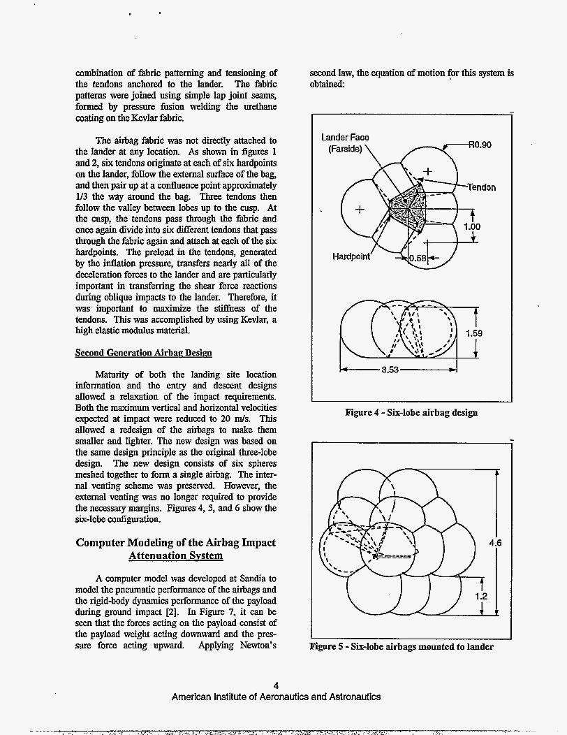
Maturity of both the landing site location information and the entry and descent designs allowed a relaxation of the impact requirements. Both the maximum vertical and horizontal velocities expected at impact were reduced to 20 d s . This allowed a redesign of the airbags to make them smaller and lighter. The new design was based on the same design principle as the original three-lobe design. The new design consists of six spheres meshed together to form a single airbag. The inter- nal venting scheme was preserved. However, the external venting was no longer required to provide the necessary margins. Figures 4,5, and 6 show the six-lobe configuration.
Computer Modeling of the Airbag Impact Attenuation System
A computer model was developed at Sandia to model the pneumatic performance of the airbags and the rigid-body dynamics performance of the payload during ground impact [2]. In Figure 7, it can be Seen that the forces acting on the payload consist of the payload weight acting downward and the pres- sure force acting upward. Applying Newton's
second law, the equation of motion for this system is obtained:
Lander Face
(Farside) \
Hardpoint
L - 3 . 5 3 , 1
Figure 4 - Six-lobe airbag design
I I
Figure 5 - Six-lobe airbags mounted to lander
4 American Institute of Aeronautics a n d Astronautic;

Riid Body Lander Elottom Aihags
Z
Figure 6 - Exploded view of Dyna-3D finite element model, six-lobe airbag design (Model created by Marc Collier and John McKinney of Rockwell Aerospm: Space Systems Division)
The nitrogen gas that was contained in all of the bags was assumed to perform as a perf& gas. The mass of gas contained in each bag was calcu- lated from the known gas pressure, temperature, and bag volume.
+X. Direction
Gravitational nde Orifiie Acceleiation
External t
Figure 7 - Impact Attenuation System Sketch
Because all of the top bags communicated pneumatically with the bottom bag, the gas con- tained within them was assumed to be at the same
5
pressure and temperature before impact. Just before impact, external orifices could be opened in the bottom bag and gas could start flowing out to the local environment from the bottom bag. At impact, the volume of the bottom bag began to decrease. If the external orifices were not too large, the gas pressure in the bottom bag would begin to increase forcing gas back into the top bags as well as to the outside. If the external orifices were too large, the pressure in the bottom bag would continue to decrease and the gas in the top bags would continue to flow into the bottom bag until the diaphragm expanded to fill the remaining volume of the bottom bag. At that time, gas would cease flowing from the external orifices.
Gas flow through an orifice can be subsonic or sonic depending on the static pressure ratio of the gas downstream to that of the gas upstream. For a diatomic gas, such as nitrogen, if the static pressure ratio is greater than 0.5283, the flow is subsonic up to and through the smallest flow area, the orifice. If the ratio is smaller than 0.5283, the flow is subsonic as it approaches, but sonic in the orifice [3].
To slow the impacting payload, its kinetic energy must be transferred into the potential energy of the compressed gas. Thus, the airbags must
American Institute of Aeronautics and Astronautic;
.. _- .,. ,, .:: ,,'_ 2. .P",>*' :i: I ' - : - ' > ' - ?.-m-M,.-,: -%r' 7 ~. .-

operate with an absolute internal pressure that is greater than the local atmospheric pressure to generate a force which, acting through the deflection of the bag, does work on the payload, An airbag impact attenuation system intended for use on Mars can be tested ip the earth's atmospheric pressure with the intended initial pressure differential from the bag interior to the atmosphere, but the external orifices will not perform as they would on Mars since the pressure ratio across them is significantly Werent.
The mass of gas discharged through the exter- nal orifices and the mass of gas remaining in the bag directly af fec t the rebound of the payload, so an atmospheric test on earth would not exhibit the same initial rebound speed as would actually occur on Mars.
The mass flow rate at the orifice throat (subscript th) is:
dw dt - = Mthpthuth
The gas density at the throat of the orifice is:
(3)
and the gas velocity at the throat in terms of sonic conditions is:
where:
When equations 3-5 are factored into equation 2, the mass flow rate is expressed in terms of the pressure and temperature in the orifice throat.
Since the average gas flow within a bag is nearly zero, the static pressure and the stagnation pressure in the bag are essentially equal. Hence the static pressure in the orifice throat as a function of the pressure upstream of the orifice is [4]:
Y - p.++ ( y - l ) M i 1 ' 1-Y . P U
0
When equation 7' is solved for M and substituted along with the adiabatic equation into equation 6, the equation for rhe mass flow rate through a sub- sonic orifice is obitained
For sonic flow in the orifice, M=l.O, and equation 7 reduces to:
(9)
Substituting the adiabatic equation and equation 9 into equation 6 and rearranging produces the equation for the nms flow through a sonic orifice.
Discharpe Coefficient
Both equations 8 and 10 depend upon the value of the orifice discharge coefficient, k. Experiments have been perfonned [5] in which the pressure dif- ferential across a sharp-edged orifice was varied to obtain subcritical (subsonic) and critical (sonic) flow conditions. Experimental values of k measured as a function of the ratio of downstream to upstream pressure for the range from 0.0 to 1.0 were included in the model.
Each top bag can exchange gas only with the bottom bag through its internal orifices. The mass flow rate, dW/dt, is determined by equation 8 or 10 depending on whether the orifice flow is subsonic or sonic. If the pressure differential causes flow from the bottom bag into the three top bags, that flow rate is considered to be negative and the mass of gas in the top bags increases.
6 American Institute of Aeronautics and Astronautics

The bottom bag can exchange gas with the three top bags through the internal orifices and also with the outside through the external orifices. Gas flow out of the bottom bag, whether through the internal or external orifices, is considered to be nega- tive. Thus, flow into the top bags and to the atmos- phere will decrease the mass of gas contained in the bottom bag.
ChanPe in Bottom Bag Area and Volume
The airbags proposed for the lander were con- structed of fabric and restrained with external and internal tendons so that each appeared to consist of three or more spherical bags merged together.
As shown in equation 1, the force that acts to decelerate the payload depends directly upon the area of the footprint (Am) of the bag with the ground. The internal pressure in the bottom bag which is being crushed also depends directly upon the change in the bag’s volume. Note that an implicit assump- tion made in developing the area and volume equations for each bag design was that the parts of the bottom bag not in contact with the ground did not move nor flex relative to the lander. The area of the footprint as a function of the bag crushup was calculated for each bag configuration based strictly upon the bag geometry and the area of the bag that would be intersected by the plane of the ground during crushup.
The computational technique used to solve for the bag crushup and pneumatic changes of the system were adopted fiom those described in reference 6.
Bounce Eauations
Since the gas remaining in the bags after the payload has been successfully stopped is sti l l at a pressure greater than the local atmospheric pressure, the payload experiences some rebound (bounce). The same governing equation which calculates the transfer of the payload’s kinetic energy into potential energy stored in the compression of the gas also cal- culates the reverse transfer of energy fiom the gas to the payload. The maximum velocity for a rebound is achieved at the instant the airbag ceases to push on the payload. This occurs when the airbag has rein- flated to its original shape or when the pressure in the bag reaches the local atmospheric pressure. The height of the bounce, assuming no aerodynamic drag, is found by simply equating the payload‘s
7
kinetic energy at the start of the rebound with its potential energy at the top of the r&und.
Modeling
The feasibility of using airbags to cushion the lander payload during ground impact on Mars had to be proven through testing on Earth. A modeling study was made to determine what test conditions were required to obtain meaningfd data.
The Buckingham Pi Theorem [7] states that the number of non-dimensional numbers required to define a problem is equal to the total number of vari- ables minus the total number of dimensions in- volved. There are: 19 variables and four dimensions; mass, length, time and temperature in this problem. Thus, 15 non-dimensional numbers are needed.
These non-dimensional numbers can be obtained in many ways that often seem somewhat arbitrary. Once generated, they can be modified by multiplication or division with any combination of the other non-dimensional numbers that are involved. In this case, the more complicated non- dimensional numbers were chosen fiom the coefficients in the non-dimensional governing differential equations. Note that the product of the gas constant and the temperature was considered as one variable sino: they were the only ones in this problem that contained the dimension of temperature. Doing this did not af€& the quantity of non-dimensional numbers required, because both the number of variables and the number of dimensions were decrease by one. Fifteen non- dimensional numbers were obtained.
Let the system being tested on Earth be the “prototype77, denoted by the subscript, P, and the system that is to impact on another planet be the “full-scale system”, denoted by the subscript, F. For the results of a pxototype test to be very meaningful a l l of the prototype non-dimensional numbers must equal their counterparts for the full-scale. When this occurs the modeling is called “~ndistorted.~’
Assume that the geometric scaling factor between the prototype and the full-scale is:

and that the pressure ratio between the prototype and the full-scale is:
n=-. PP
PF Then equating the non-dimensional numbers between the prototype and the full-scale produces the following relationships between the variables:
ap = (+).aF
The last equation shows the relationship that must be preserved between all of the prototype and full-scale accelerations. Hence, for the modeling to be undistorted:
The gravitational acceleration for the prototype is that of Earth, and for the full-scale, that of Mars where the lander will impact. Therefore, the ratio of the gravitational acceleration between Earth and Mars prescribes the model scale, h = 0.38, for undistorted model testing in full Earth gravity.
The feature, n, was added to the modeling equations to free the prototype mass from having to be exactly h3 times the full-scale mass. his proved useful during the design of the High Altitude Chamber impact apparatus and in the development of the test program parameters.
These modeling relationships also prescribe how the measurements made during prototype impact tests can be used to predict the full-scale impact on Mars. Full-scale velocities are equal to prototype velocities. Full-scale accelerations are h times prototype accelerations. If the same gas at the same initial temperature is used in the full-scale and prototype, then temperature variations will be the same between the full scale and prototype impacts.
Prototvne Airbag Test Program
Hhh Altitude Chamber Test Series #l.
A test series of the original design was per- formed in May 1993 in the Sandia High Altitude Chamber (HAC). The impact test apparatus shown in Figure 8 was designed, fabricated, and assembled in the HAC for these tests [SI. Because accelerating the airbag system itself was impractical in the lim- ited space of the HAC the "ground" was accelerated into the statiomy, inverted, lander/ airbag system, which was mounted on a strut. To perform a test the impact plate was elevated and attached to a restramn - ' gcable. AfterthepressureintheHACwas brought to test conditions the bungee cords were stretched to equal tension and the impact plate was released through initiation of an explosive cable cutter. The impact plate was then accelerated towards the stationary airbag system by the bungee cords. Just before impact the bungee cords went slack and the velocity of the impact plate was measured by an optical velocity trap. Instnunenta- tion on the impact plate and in each of the airbags
'measured the deceleration and pressure-time history of the event [9].
The impact plate was designed for minimal mass, but still exceeded the scaled mass of the MI- scale system by a factor of two. The scaling model therefore required that the pressures (both internal and external) be doubled to provide a suitable simu- lation of deceleration. The tests were performed at a pressure of 2.0 lcPa (0.290 psi) external pressure, about twice that of the Martian atmosphere. The airbags were tested with initial internal pressures of 8.0 kPa (1.16 psi) and 12.0 kPa (1.74 psi).
Eighteen impact tests were performed with variations in impact velocity (maximum of 20 d s ) , external orifice areas, and internal orifice areas. The tests validated the mathematical computer model and demonstrated that the timing for external vent opening was critical. These tests also showed that due to the location of the external vents the opening of the vents was severely affected by the crushup of the bags and not repeatable. A modified code that tailored the external orifice area as a function of stroke as measured in the video documentation was prepared and used to model the airbag system. Very good correlation between the simulation and the test data was obtained.
8 American Institute of Aeronautics a n d Astronautics

The results of these tests indicated that the per- formance of the airbag system was marginal for pro- tecting the lander to less than the 50 g deceleration limit without the external vents. A decision was made to add the retro-rocket system to the descent
Impact Plate \
TOP VIEW
k
and landing system in lieu of the extfmal vents. The retro-rocket systcm decreases the vertical velocity component and slllowed the airbags to be decreased in size.
Impact Plate B Beam '
w-1 / Cutter
Vertical Channels
Vertical Channets
/
Figure 8 - Mars Impact Test Apparatus (top bags removed for clarity)
Covote Canvon Test Series
A test series was required to evaluate the struc- tural integrity of the airbag impact attenuation system and demonstrate system feasibility. Free fall drops of the system were needed at representative velocities to meet this requirement.
The Coyote Canyon Test Facility at Sandia National Laboratories, which consists of a cable sus- pended across a valley between two mountain ridges, was chosen as the site for this test series. The cable facility pr0vides.a drop height of approximately 183 meter (600 feet) at the highest point above the valley floor. In the initial test series the airbags were dropped vertically from the cable. A 147 kg (325 lb) mass was attached to the bottom of the airbag system to accelerate the system to a desired impact velocity.
At impact the cable attaching the weight was severed so that the airbag system could rebound naturally.
The first test of the system at 12 m/s impact velocity was successful; however, the second 20 m/s impact test caused substantial damage to the airbag structure. It should be noted, however, that the lander was still protected during this impact and did not exceed the 50 g deceleration limit. The two pri- mary causes for the damage to the airbags were inadequate strain relief in the basic construction and faulty load paths at the tendon passthroughs. This problem was alleviated in the second prototype by creating a more direct tendon load path and by using nylon fabric locally around the passthroughs. The flight design is avoiding this problem completely by creating an enlarged inverted fabric boot to form the passthrough. The boot prevents any membrane loading in the vicinity of the hardpoint.
9 American Institute of Aeronautics and Astronautics

The second prototype bag was tested with both vertical and horizontal components of velocity. This test was conducted by accelerating the airbag system down an inclined wire on a trolley designed by JPL. Five tests were conducted at velocities up to 25.6 mls total velocity. For the last test, a simulated Martian rocky surface w k prepared. The airbags and lander survived all of these tests with the only damage being a four-inch tear in the fabric on the iinal test. Figure 9 shows an impact sequence from these tests.
Figure 9 - Canyon Test Airbag Impact
HAC Test Series #2.
A second HAC test series was conducted in mid-September 1994. The purpose of this series was to demonstrate performance of the second generation airbag design under the same conditions 'as the original design and to validate the mathematical predictions used to size and design this second gen- eration system. One of the major performance pa- rameters investigated in th is test series was the size of the internal orifices. The computer model pre-
10
dicts an optimal size that minimizes the deceleration and also .the rebound. In addition, tests were conducted to demonstrate performance of the airbags when impact occufs on a top bag or on three bags at an apex'
The same impact apparatus used for the first test series in the HAC was reused for this series of tests. In addition, a tripod stand was constructed to support the lantier/airbag system with an apex pointed upward. This allowed investigation of an impact on the "apex" of the airbags where the foot- print area impacting the ground is smallest.
The impact 'test results were then compared to the computer model. The results were not consistent with the computer model; however, examination of the test video showed that flexing of the airbags invalidated one of the code assumptions. A pneu- matic volume module was added to the code to com- pensate for the main bag flexing below the original bottom plane of &le lander. Also the footprint area and volume of the impact bag were calculated from the impact data and inserted into the computer model. These dah more accurately modeled the area and volume of the: system as it flexed away from the impact plate. Finally, the flow through the internal orifices of the sxond generation airbags did not appear to be properly modeled by a sharp edged orifice. A constarit flow coefficient of 0.98 was used to model th is flow. This modified code more accu- rately models the impact attenuation system results. Figures 10 and 11. illustrate the bottom bag pressure and deceleration test data and the code simulation curve.
L
v) a,
5 150 175 200 225 250 275 WO
Time(msec) . Figure 10 -Pressure versus Time

I b
25
n
- ! 0 cn C 0
a
U
.- 3 -25
2 -50
-
-75 150 175 200 225 250 275 300
Time (msec) Figure 11 - Acceleration vs. Time
FIiPht System Testing
The test program described in this paper was considered proof of concept work to demonstrate the feasibility of using an airbag system for a planetary lander. In support of the flight article to be sent to Mars, JPL and ILC Dover Inc. have designed and are performing a much more extensive and 'detailed series of tests. These tests are all conducted with full scale airbags under Mars pressure conditions. The tests include, but are not limited to; retraction testing, rapid inflation testing at Mars temperature and pressure, and full speed drop testing onto a 60' slanted platform with 0.5 meter high rocks. The results of these tests will validate and qualify the flight airbag and gas generator designs.
Conclusions and Recommendations
An impact attenuation system for the Mars Pathfinder spacecraft has been designed, a prototype 0.38 scale model fabricated, a computer model pre- pared, and tests conducted. This feasibility program has demonstrated that the Airbag Impact Attenuation design will protect the Mars Pathfinder lander upon impact with the Martian surface. A contract for the flight test bag fabrication and dem- onstration program has been issued to ILC Dover Inc. as part of the preparations for the November 1996 launch.
The computer code developed and validated for performance of the airbag system provides a tool for investigating performance of the full-scale system in the Martian environment. Parametric studies can be
performed to investigate variations in impact velocity, internal .and external pressire, internal vent areas, and lander mass. Also, modifications to the airbag system geometry can be investigated by changing the area and volume inputs in the code. The computer a l e is currently limited, however, to 3nvestigation of vertical impacts on the bottom bag.
&knowledgments
The authors wish to acknowledge the contribu- tions and support of Bob Croll, John Henfling, Don McKenzie, and Ed Clark for the High Altitude Chamber test; Ed Constantineau for the design and fabrication of the impact apparatus; Lany Whinery and Dan Luna for fabrication of the prototype airbags; and Mark Garrett and Jim Calderone for the Coyote Canyon test series.
References
[l] Ross, R.G. Jr., Layman, W.E., The Design and Test- ing of an Inflated Sphere Impact Limiter, NASA TR
[2] Cole, J. K. and Waye, D. E., BAG: A Code for Pre- dicting the Pefonnance of a Gas Bag Impact Attenuation System for the PAi'HELWm Lunder, Sandia National Laboratories, Albuquerque, NM, SAND93-2133, November 1993.
[3] Liepmann, IE. W. and Roshko, A, Elements of Gas Qmmics , John Wiley & Sons, 1957.
[4] Ames Research S W , Equations, Tables and Charts for Compressible Flow, National Advisory Committee for Aeronautics, Ames Aeronautical Laboratory Report 1135.
[5] Perry, J. A., Jr., Critical Flow Through Sharp-Edged Onijces, Transactions of the American Society of Mechanical Engineers, October 1949, pp. 757-764.
[6] Esgar, Jack B. and Morgan, William C., Analytical Study of Soft bhdings on Gas-Filled Bags, NASA Lewis Research Center, Cleveland, OH, Technical
[q Murphy, Glenn, Similitude in Engineering, The Ronald Press Company, New York, NY, 1950.
[8] Cole, J. IC., Waye, D. E., Croll, R. H., and Constanheau, E. J., An Apparnius for Testing the PATHFluDER Lander Gas Bag Impact Attenuation System, Sandia National Laboratories, Albuquerque, NM, to be published.
[9] Clark, E. L., "Data Acquisition, Conversion, and Analysis for the MESUR Pathfinder High 'Altitude Chamber Test, 1994," Sandia National Laboratories, Albuquerque, NM, in possession of author.
NO 32-1037, December 15,1966.
.
Report R-75, I h C h 16,1960.