Embed Size (px)
Citation preview

Martin® Air Cleaner
Operator’s Manual M3918

Martin Engineering M3918-02/15 i Martin® Air Cleaner
Table of Contents
Section PageList of Figures . . . . . . . . . . . . . . . . . . . . . . . . . . . . . . . . . . . . . . . . . . . . . . . . . . . . . . . . . . . . ii
Introduction . . . . . . . . . . . . . . . . . . . . . . . . . . . . . . . . . . . . . . . . . . . . . . . . . . . . . . . . . . . . . . 1General . . . . . . . . . . . . . . . . . . . . . . . . . . . . . . . . . . . . . . . . . . . . . . . . . . . . . . . . . . . . . . . . . . . . . . 1
Location requirements for transfer point installations . . . . . . . . . . . . . . . . . . . . . . . . . . . . . . . . . . 1
References . . . . . . . . . . . . . . . . . . . . . . . . . . . . . . . . . . . . . . . . . . . . . . . . . . . . . . . . . . . . . . . . . . . 1
Safety . . . . . . . . . . . . . . . . . . . . . . . . . . . . . . . . . . . . . . . . . . . . . . . . . . . . . . . . . . . . . . . . . . . . . . . 2
Materials required . . . . . . . . . . . . . . . . . . . . . . . . . . . . . . . . . . . . . . . . . . . . . . . . . . . . . . . . . . . . . 2
Before Installing Air Cleaner. . . . . . . . . . . . . . . . . . . . . . . . . . . . . . . . . . . . . . . . . . . . . . . . . 3
Installing Air Cleaner. . . . . . . . . . . . . . . . . . . . . . . . . . . . . . . . . . . . . . . . . . . . . . . . . . . . . . . 4Electrical connections . . . . . . . . . . . . . . . . . . . . . . . . . . . . . . . . . . . . . . . . . . . . . . . . . . . . . . . . . . 9
Installing timer enclosure. . . . . . . . . . . . . . . . . . . . . . . . . . . . . . . . . . . . . . . . . . . . . . . . . . . . . . . . 10
Initial Operation of Air Cleaner. . . . . . . . . . . . . . . . . . . . . . . . . . . . . . . . . . . . . . . . . . . . . . . 13
Maintenance. . . . . . . . . . . . . . . . . . . . . . . . . . . . . . . . . . . . . . . . . . . . . . . . . . . . . . . . . . . . . . 14Replacing Filters . . . . . . . . . . . . . . . . . . . . . . . . . . . . . . . . . . . . . . . . . . . . . . . . . . . . . . . . . . . . . . 16
Part Numbers . . . . . . . . . . . . . . . . . . . . . . . . . . . . . . . . . . . . . . . . . . . . . . . . . . . . . . . . . . . . . 17
Tab
le o
f C
onte
nts
Martin Engineering M3918-02/15 ii Martin® Air Cleaner
List of Figures
Figure Title Page1 Lifting Air Cleaner . . . . . . . . . . . . . . . . . . . . . . . . . . . . . . . . . . . . . . . . . . . . . . . . 4
2 Dimensions for Martin® Air Cleaner, P/N DFAC-10XXXXXX . . . . . . . . . . . . . 5
3 Dimensions for Martin® Air Cleaner, P/N DFAC-15XXXXXX . . . . . . . . . . . . . 6
4 Dimensions for Martin® Air Cleaner, P/N DFAC-20XXXXX. . . . . . . . . . . . . . . 7
5 Dimensions for Martin® Air Cleaner, P/N DFAC-30XXXXX. . . . . . . . . . . . . . . 8
6 Electrical and Plumbing Detail . . . . . . . . . . . . . . . . . . . . . . . . . . . . . . . . . . . . . . . 9
7 Solenoid Enclosure . . . . . . . . . . . . . . . . . . . . . . . . . . . . . . . . . . . . . . . . . . . . . . . . 10
8 Solenoid Wiring Schematic . . . . . . . . . . . . . . . . . . . . . . . . . . . . . . . . . . . . . . . . . 11
9 Solenoid Enclosure Heater Option Wiring Schematic . . . . . . . . . . . . . . . . . . . . . 11
10 Timer Enclosure Electrical Connections. . . . . . . . . . . . . . . . . . . . . . . . . . . . . . . . 12
11 Replacing Filters . . . . . . . . . . . . . . . . . . . . . . . . . . . . . . . . . . . . . . . . . . . . . . . . . . 16
12 Martin® Air Cleaner, P/N DFAC-10XXXXXX . . . . . . . . . . . . . . . . . . . . . . . . . . 19
13 Martin® Air Cleaner, P/N DFAC-15XXXXXX . . . . . . . . . . . . . . . . . . . . . . . . . . 22
14 Martin® Air Cleaner, P/N DFAC-20XXXXX . . . . . . . . . . . . . . . . . . . . . . . . . . . 25
15 Martin® Air Cleaner, P/N DFAC-30XXXXX . . . . . . . . . . . . . . . . . . . . . . . . . . . 28
List of Tables
Table Title PageI Pressure Settings . . . . . . . . . . . . . . . . . . . . . . . . . . . . . . . . . . . . . . . . . . . . . . . . . . 13
II Replacement Parts List . . . . . . . . . . . . . . . . . . . . . . . . . . . . . . . . . . . . . . . . . . . . . 18
III Martin® Air Cleaner Part Numbers and Quantities . . . . . . . . . . . . . . . . . . . . . . . 21
IV Martin® Air Cleaner Part Numbers and Quantities . . . . . . . . . . . . . . . . . . . . . . . 24
V Martin® Air Cleaner Part Numbers and Quantities . . . . . . . . . . . . . . . . . . . . . . . 27
VI Martin® Air Cleaner Part Numbers and Quantities . . . . . . . . . . . . . . . . . . . . . . . 30
Lis
t of
Fig
ures
& T
able
s
Martin Engineering M3918-02/15 1 Martin® Air Cleaner
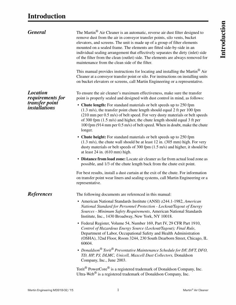
Introduction
General The Martin® Air Cleaner is an automatic, reverse air dust filter designed to remove dust from the air in conveyor transfer points, silo vents, bucket elevators, and screens. The unit is made up of a group of filter elements mounted on a sealed frame. The elements are fitted side-by-side in an individual sealing arrangement that effectively separates the dirty (inlet) side of the filter from the clean (outlet) side. The elements are always removed for maintenance from the clean side of the filter.
This manual provides instructions for locating and installing the Martin® Air Cleaner at a conveyor transfer point or silo. For instructions on installing units on bucket elevators or screens, call Martin Engineering or a representative.
Location requirements for transfer point installations
To ensure the air cleaner’s maximum effectiveness, make sure the transfer point is properly sealed and designed with dust control in mind, as follows:
• Chute length: For standard materials or belt speeds up to 250 fpm(1.3 m/s), the transfer point chute length should equal 2 ft per 100 fpm (210 mm per 0.5 m/s) of belt speed. For very dusty materials or belt speeds of 300 fpm (1.5 m/s) and higher, the chute length should equal 3 ft per 100 fpm (914 mm per 0.5 m/s) of belt speed. When in doubt, make the chute longer.
• Chute height: For standard materials or belt speeds up to 250 fpm (1.3 m/s), the chute wall should be at least 12 in. (305 mm) high. For very dusty materials or belt speeds of 300 fpm (1.5 m/s) and higher, it should be at least 24 in. (610 mm) high.
• Distance from load zone: Locate air cleaner as far from actual load zone as possible, and 1/3 of the chute length back from the chute exit point.
For best results, install a dust curtain at the exit of the chute. For information on transfer point wear liners and sealing systems, call Martin Engineering or a representative.
References The following documents are referenced in this manual:
• American National Standards Institute (ANSI) z244.1-1982, American National Standard for Personnel Protection - Lockout/Tagout of Energy Sources - Minimum Safety Requirements, American National Standards Institute, Inc., 1430 Broadway, New York, NY 10018.
• Federal Register, Volume 54, Number 169, Part IV, 29 CFR Part 1910, Control of Hazardous Energy Source (Lockout/Tagout); Final Rule, Department of Labor, Occupational Safety and Health Administration (OSHA), 32nd Floor, Room 3244, 230 South Dearborn Street, Chicago, IL 60604.
• Donaldson® Torit® Preventative Maintenance Schedule for DF, DFT, DFO, TD, HP, PJ, DLMC, Unicell, Maxcell Dust Collectors, Donaldson Company, Inc., June 2003.
Torit® PowerCore® is a registered trademark of Donaldson Company, Inc.Ultra-Web® is a registered trademark of Donaldson Company, Inc.
Intr
oduc
tion
Martin Engineering M3918-02/15 2 Martin® Air Cleaner
Safety All safety rules defined in the above documents and all owner/employer safety rules must be strictly followed when working on this equipment.
Materials required In addition to standard hand tools, a hoist is required to install this equipment.
Intr
oduc
tion

Martin Engineering M3918-02/15 3 Martin® Air Cleaner
Before Installing Air Cleaner
IMPORTANTThe delivery service is responsible for damage occurring in transit. Martin Engineering CANNOT enter claims for damages. Contact your transportation agent for more information.
1. Inspect shipping container for damage. Report damage to delivery service immediately and fill out delivery service’s claim form. Keep any damaged goods subject to examination.
2. Remove air cleaner from shipping container. Equipment in container should include air cleaner and controller.
3. If anything is missing, contact Martin Engineering or representative.
WARNING!
Before installing equipment, turn off and lock out/tag out energy source to conveyor and conveyor accessories.
4. Turn off and lock out/tag out energy source according to ANSI standards (see “References”).
WARNING!
If equipment will be installed in an enclosed area, gas level or dust content must be tested before using a cutting torch or welding. Using a cutting torch or welding in an area with gas or dust may cause an explosion.
5. If using a cutting torch or welding, test atmosphere for gas level or dust content. Cover conveyor belt with fire retardant cover.
Bef
ore
Inst
alla
tion
Martin Engineering M3918-02/15 4 Martin® Air Cleaner
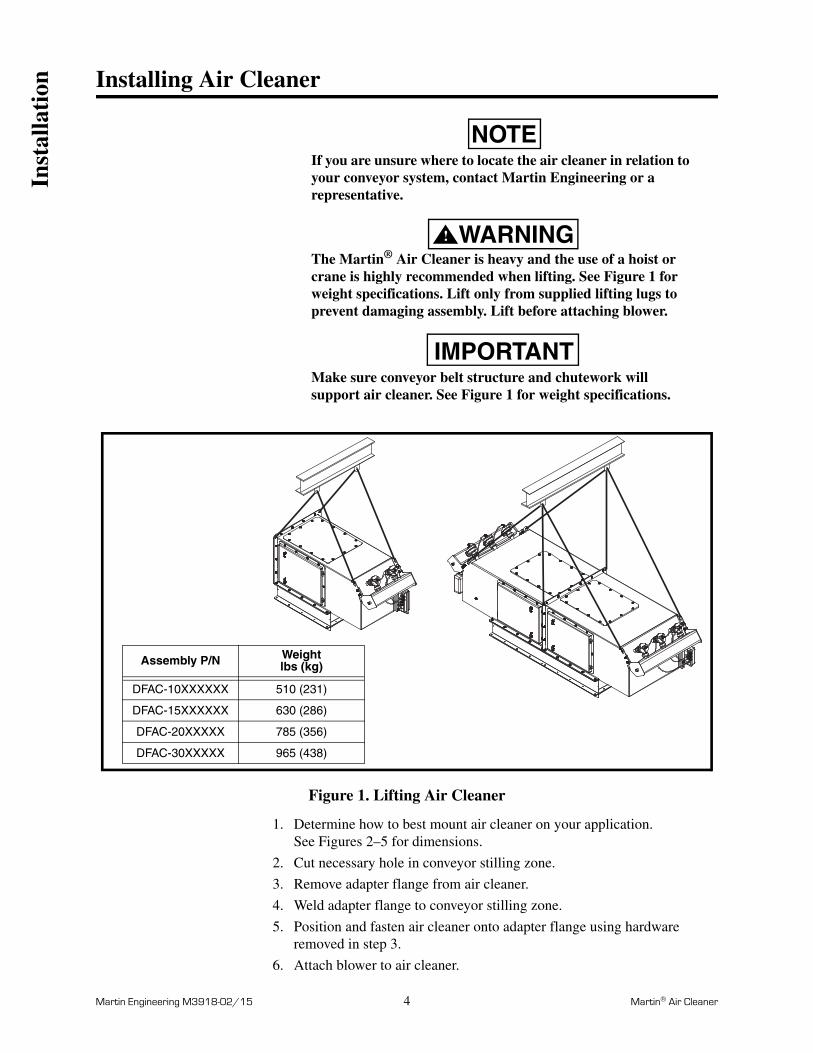
Installing Air Cleaner
NOTEIf you are unsure where to locate the air cleaner in relation to your conveyor system, contact Martin Engineering or a representative.
WARNING!
The Martin® Air Cleaner is heavy and the use of a hoist or crane is highly recommended when lifting. See Figure 1 for weight specifications. Lift only from supplied lifting lugs to prevent damaging assembly. Lift before attaching blower.
IMPORTANTMake sure conveyor belt structure and chutework will support air cleaner. See Figure 1 for weight specifications.
Figure 1. Lifting Air Cleaner
1. Determine how to best mount air cleaner on your application. See Figures 2–5 for dimensions.
2. Cut necessary hole in conveyor stilling zone.
3. Remove adapter flange from air cleaner.
4. Weld adapter flange to conveyor stilling zone.
5. Position and fasten air cleaner onto adapter flange using hardware removed in step 3.
6. Attach blower to air cleaner.
Assembly P/N Weightlbs (kg)
DFAC-10XXXXXX 510 (231)
DFAC-15XXXXXX 630 (286)
DFAC-20XXXXX 785 (356)
DFAC-30XXXXX 965 (438)
Inst
alla
tion
Martin Engineering M3918-02/15 5 Martin® Air Cleaner
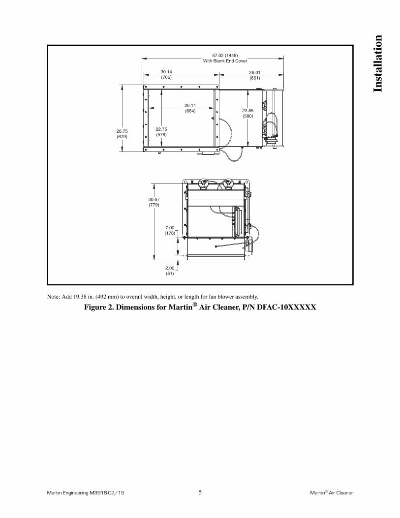
Note: Add 19.38 in. (492 mm) to overall width, height, or length for fan blower assembly.
Figure 2. Dimensions for Martin® Air Cleaner, P/N DFAC-10XXXXX
22.75(578)
26.14(664)
26.75(679)
22.85(580)
30.14(766)
26.01(661)
57.02 (1448)With Blank End Cover
30.67(779)
7.00(178)
2.00(51)
Inst
alla
tion

Martin Engineering M3918-02/15 6 Martin® Air Cleaner
Note: Add 27.25 in. (692 mm) to overall width, height, or length for fan blower assembly.
Figure 3. Dimensions for Martin® Air Cleaner, P/N DFAC-15XXXXX
32.75(832)
26.14(664)
36.75(933) 32.85
(834)
30.14(766)
26.01(661)
57.02 (1448)With Blank End Cover
30.67(779)
7.00(178)
2.00(51)
Inst
alla
tion
Martin Engineering M3918-02/15 7 Martin® Air Cleaner
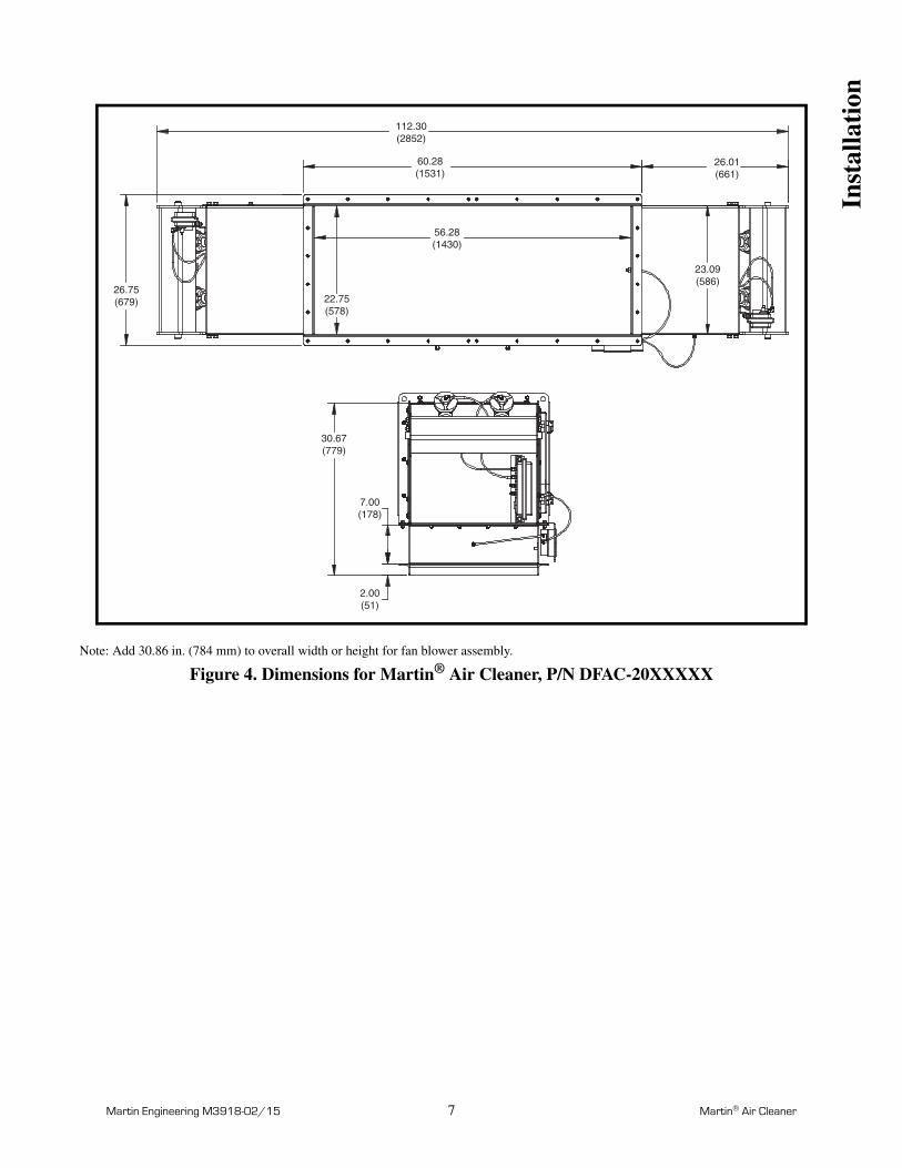
Note: Add 30.86 in. (784 mm) to overall width or height for fan blower assembly.
Figure 4. Dimensions for Martin® Air Cleaner, P/N DFAC-20XXXXX
22.75(578)
23.09(586)
56.28(1430)
26.01(661)
112.30(2852)
26.75(679)
60.28(1531)
30.67(779)
7.00(178)
2.00(51)
Inst
alla
tion

Martin Engineering M3918-02/15 8 Martin® Air Cleaner
Note: Add 33.16 in. (842 mm) to overall width or height for fan blower assembly.
Figure 5. Dimensions for Martin® Air Cleaner, P/N DFAC-30XXXXX
32.75(832)
33.09(840)
56.28(1430)
26.01(661)
112.30(2852)
36.75(933)
60.28(1531)
30.67(779)
7.00(178)
2.00(51)
Inst
alla
tion
Martin Engineering M3918-02/15 9 Martin® Air Cleaner
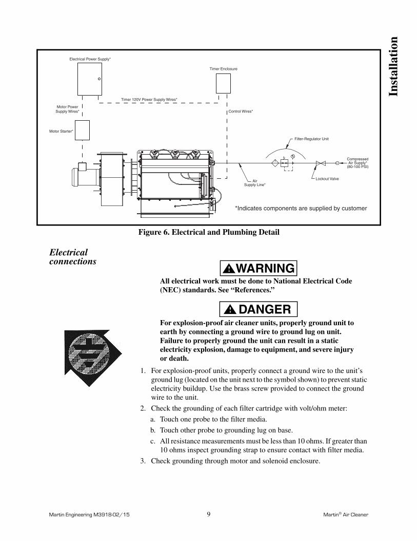
Figure 6. Electrical and Plumbing Detail
Electrical connections
WARNING!
All electrical work must be done to National Electrical Code (NEC) standards. See “References.”
DANGER!
For explosion-proof air cleaner units, properly ground unit to earth by connecting a ground wire to ground lug on unit. Failure to properly ground the unit can result in a static electricity explosion, damage to equipment, and severe injury or death.
1. For explosion-proof units, properly connect a ground wire to the unit’s ground lug (located on the unit next to the symbol shown) to prevent static electricity buildup. Use the brass screw provided to connect the ground wire to the unit.
2. Check the grounding of each filter cartridge with volt/ohm meter:
a. Touch one probe to the filter media.
b. Touch other probe to grounding lug on base.
c. All resistance measurements must be less than 10 ohms. If greater than 10 ohms inspect grounding strap to ensure contact with filter media.
3. Check grounding through motor and solenoid enclosure.
Electrical Power Supply*
Timer Enclosure
Control Wires*
Motor Starter*
Timer 120V Power Supply Wires*
Motor PowerSupply Wires*
*Indicates components are supplied by customer
Filter-Regulator Unit
CompressedAir Supply*
(80-100 PSI)
Lockout ValveAirSupply Line*
Inst
alla
tion
Martin Engineering M3918-02/15 10 Martin® Air Cleaner
WARNING!
Before making any connections, lock out/tag out electrical supply to control system according to ANSI standards (see “References”).
4. Connect blower motor to power supply:
a. Determine power requirements for motor.
b. Install a motor starter (not included) per local requirements and codes.
c. Interlock motor and timer enclosure and control per plant PLC.
Installing timer enclosure
CAUTION!
Do not mount enclosure in area subject to shock, vibration, temperatures exceeding 130°F (55°C), or explosion. Damage to control system circuitry could result.
1. Determine location for timer enclosure.
2. Mount onto wall with fasteners.
3. Drill conduit holes in enclosure for solenoid and power wires. Use care not to damage internal components. Drill in most weather-proof location available on enclosure.
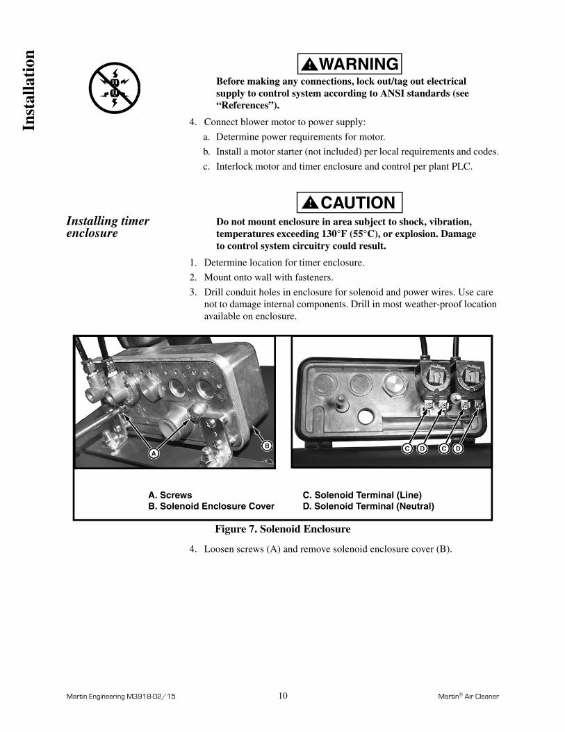
Figure 7. Solenoid Enclosure
4. Loosen screws (A) and remove solenoid enclosure cover (B).
A. ScrewsB. Solenoid Enclosure Cover
C. Solenoid Terminal (Line)D. Solenoid Terminal (Neutral)
Inst
alla
tion
Martin Engineering M3918-02/15 11 Martin® Air Cleaner
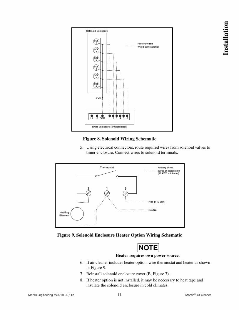
Figure 8. Solenoid Wiring Schematic
5. Using electrical connectors, route required wires from solenoid valves to timer enclosure. Connect wires to solenoid terminals.
Figure 9. Solenoid Enclosure Heater Option Wiring Schematic
NOTEHeater requires own power source.
6. If air cleaner includes heater option, wire thermostat and heater as shown in Figure 9.
7. Reinstall solenoid enclosure cover (B, Figure 7).
8. If heater option is not installed, it may be necessary to heat tape and insulate the solenoid enclosure in cold climates.
SOL6
SOL5
SOL4
SOL3
SOL2
SOL1
L1 L2 COM 1 63 4 52
COM
Factory WiredWired at Installation
Timer Enclosure Terminal Block
Solenoid Enclosure
Thermostat
HeatingElement
Hot (110 Volt)
Neutral
2 1 3
Factory WiredWired at Installation(16 AWG minimum)
Inst
alla
tion
Martin Engineering M3918-02/15 12 Martin® Air Cleaner
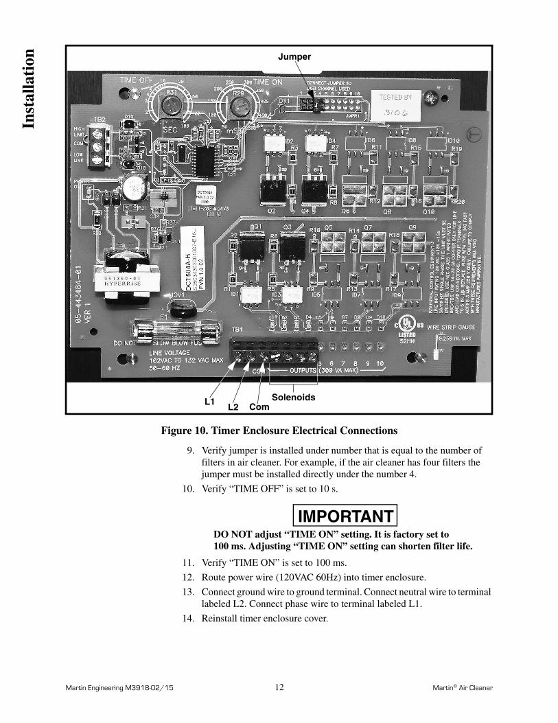
Figure 10. Timer Enclosure Electrical Connections
9. Verify jumper is installed under number that is equal to the number of filters in air cleaner. For example, if the air cleaner has four filters the jumper must be installed directly under the number 4.
10. Verify “TIME OFF” is set to 10 s.
IMPORTANTDO NOT adjust “TIME ON” setting. It is factory set to 100 ms. Adjusting “TIME ON” setting can shorten filter life.
11. Verify “TIME ON” is set to 100 ms.
12. Route power wire (120VAC 60Hz) into timer enclosure.
13. Connect ground wire to ground terminal. Connect neutral wire to terminal labeled L2. Connect phase wire to terminal labeled L1.
14. Reinstall timer enclosure cover.
L1L2 Com
Solenoids
Jumper
Inst
alla
tion

Martin Engineering M3918-02/15 13 Martin® Air Cleaner
Initial Operation of Air Cleaner
IMPORTANTRead entire section before beginning work.
WARNING!
Air cleaner may produce loud noise when mounted on structure. See OSHA 1910.95 for guidelines. If required, wear ear protection to avoid impairment or loss of hearing.
1. If air cleaner produces loud noise according to OSHA 1910.95, wear ear protection.
WARNING!
Failure to remove tools from installation area and conveyor belt before turning on energy source can cause serious injury to personnel and damage to belt.
2. Remove all tools and fire retardant cover from installation area and conveyor belt.
DANGER!
Do not touch or go near conveyor belt or conveyor accessories when conveyor belt is running. Body or clothing can get caught and pull body into conveyor belt, causing severe injury or death.
3. Make sure filter retention brackets are properly tightened to achieve proper filter seal.
4. Close all access doors.
5. Turn power ON at the source.
6. Start blower fan for one second, then stop.
7. Check motor and fan for the correct rotation by referencing the rotation sticker located on the motor mounting plate. Check for smooth operations of fan wheel and motor. If motor is not rotating in correct direction, lock out/tag out energy source and reverse rotation.
8. Ensure damper is set in completely closed position.
9. Turn the blower fan ON.
10. Open damper until the pressure gauge on the side of the collector matches the pressure readings in Table I.
Table I. Pressure Settings
11. Ensure fan outlet is guarded.
12. Operate and maintain air cleaner according to instructions in this manual.
13. Ensure collector is reverse pulse cleaning every ten seconds.
Material Pressure” w.g.
Cement 0.45
All other Materials 0.54
Ope
rati
on
Martin Engineering M3918-02/15 14 Martin® Air Cleaner
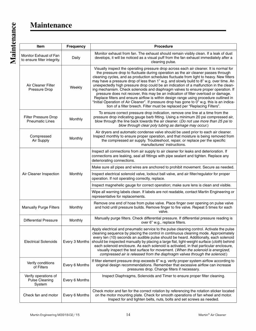
Maintenance
Item Frequency Procedure
Monitor Exhaust of Fan to ensure filter integrity. Daily
Monitor exhaust from fan. The exhaust should remain visibly clean. If a leak of dust develops, it will be noticed as a visual puff from the fan exhaust immediately after a
cleaning pulse.
Air Cleaner FilterPressure Drop Weekly
Visually inspect the operating pressure drop across each air cleaner. It is normal for the pressure drop to fluctuate during operation as the air cleaner passes through
cleaning cycles, and as production schedules fluctuate from light to heavy. New filters may have a pressure drop of less than 1” w.g. and slowly build to 8” w.g. over time. An unexpectedly high pressure drop could be an indication of a malfunction in the clean-ing mechanism. Check solenoids and diaphragm valves to ensure proper operation. If
pressure does not recover, this may be an indication of filter overload or damage. Replace filters and ensure airflow is within design range using procedure outlined in
“Initial Operation of Air Cleaner”. If pressure drop has gone to 0” w.g. this is an indica-tion of a filter breech. Filter must be replaced per “Replacing Filters”.
Filter Pressure Drop Pneumatic Lines Monthly
To ensure correct pressure drop indication, remove one line at a time from the pressure drop indicating gauge barb fitting. Using a minimum 20 psi compressed air, blow through the line back towards the air cleaner. (Do not use more than 25 psi to
blow through clear poly tubing as damage may occur.)
CompressedAir Supply Monthly
Air dryers and automatic condense valve should be used prior to each air cleaner. Inspect monthly to ensure proper operation, and that moisture is being removed from
the compressed air supply. Troubleshoot, repair, or replace per the specific manufactures’ instructions.
Air Cleaner Inspection Monthly
Inspect all connections from air supply to air cleaner for leaks and deterioration. If connections are leaking, seal all fittings with pipe sealant and tighten. Replace any deteriorating connections.
Make sure all pipes and wires are anchored to prohibit movement. Secure as needed.
Inspect electrical solenoid valve, lockout ball valve, and air filter/regulator for proper operation. If not operating correctly, replace.
Inspect magnehelic gauge for correct operation; make sure lens is clean and visible.
Wipe all warning labels clean. If labels are not readable, contact Martin Engineering or representative for replacements.
Manually Purge Filters MonthlyRemove one end of hose from pulse valve. Place finger over opening on pulse valve and hold until pressure builds. Remove finger to fire valve. Repeat 5 times for each
valve.
Differential Pressure Monthly Manually purge filters. Check differential pressure. If differential pressure reading is over 6” w.g., replace filters.
Electrical Solenoids Every 3 Months
Apply electrical and pneumatic service to the pulse cleaning control. Activate the pulse cleaning sequence by placing the control in continuous cleaning mode. Approximately every ten (10) seconds an audible pulse should be heard. Additionally, each solenoid
should be inspected manually by placing a large flat, light-weight surface (cloth) behind each solenoid enclosure. As each solenoid is activated, in that particular enclosure,
visually inspect the test surface for movement. (When the solenoid is energized, compressed air is released from the diaphragm valves through the solenoid.)
Verify conditionsof Filters Every 6 Months
If filter element pressure drop exceeds 6” w.g. verify proper system airflow according to original design recommendations. Remember that excessive airflow can increase
pressures drop. Change filters if necessary.
Verify operations of Pulse Cleaning
SystemEvery 6 Months
Inspect Diaphragms, Solenoids and Timer to ensure proper filter cleaning.
Check fan and motor Every 6 MonthsCheck motor and fan for the correct rotation by referencing the rotation sticker located
on the motor mounting plate. Check for smooth operations of fan wheel and motor. Inspect for and tighten belts, nuts, bolts and set screws as needed.
Mai
nten
ance

Martin Engineering M3918-02/15 15 Martin® Air Cleaner
Adjust exhaust Damper as needed Every 6 Months Airflow should be adjusted to match design recommendations. Excessive airflow can
shorten filter life and cause fan motor failure.
Install filters correctly During filter changes
Install new filters correctly and adequately tightened to prevent dust leakage. Improperly installed or inadequately tightened filters can allow dust to pass
through the air cleaner.
Adjust exhaust DamperImmediately
after filter changes
Because the pressure drop or restriction to airflow through the filters will decrease when new filters are installed, airflow through the air cleaner will increase. Because of
this it is necessary to adjust the fan damper to restrict the airflow through the air cleaner to the recommended level immediately after installation of new filters. As the fil-ters age and the pressure drop or restrictions to air increases, you may need to open
the damper to reach design conditions.
Item Frequency Procedure
Mai
nten
ance
Martin Engineering M3918-02/15 16 Martin® Air Cleaner
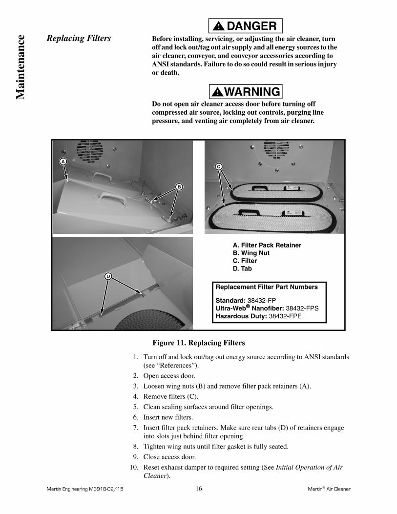
Replacing FiltersDANGER!
Before installing, servicing, or adjusting the air cleaner, turn off and lock out/tag out air supply and all energy sources to the air cleaner, conveyor, and conveyor accessories according to ANSI standards. Failure to do so could result in serious injury or death.
WARNING!
Do not open air cleaner access door before turning off compressed air source, locking out controls, purging line pressure, and venting air completely from air cleaner.
Figure 11. Replacing Filters
1. Turn off and lock out/tag out energy source according to ANSI standards (see “References”).
2. Open access door.
3. Loosen wing nuts (B) and remove filter pack retainers (A).
4. Remove filters (C).
5. Clean sealing surfaces around filter openings.
6. Insert new filters.
7. Insert filter pack retainers. Make sure rear tabs (D) of retainers engage into slots just behind filter opening.
8. Tighten wing nuts until filter gasket is fully seated.
9. Close access door.
10. Reset exhaust damper to required setting (See Initial Operation of Air Cleaner).
A. Filter Pack RetainerB. Wing NutC. FilterD. Tab
Replacement Filter Part Numbers
Standard: 38432-FPUltra-Web® Nanofiber: 38432-FPSHazardous Duty: 38432-FPE
Mai
nten
ance

Martin Engineering M3918-02/15 17 Martin® Air Cleaner
Part NumbersSee the following tables for Martin® Air Cleaner unit assembly part numbers. For replacement filter elements, manifold valves, and solenoid valves, call Martin Engineering at 800-544-2947.
10 = 1000 CFM 15 = 1500 CFM
3. The next X indicates solenoid valve type: S = Non-explosion proof service duty
E = Explosion proof service and NEMA 9 solenoid enclosure H = Same as “E” with heaters in solenoid enclosure
4. The next X indicates right side item*: F = Blower D = Door Ø = Cover Plate
5. The next X indicates top item: F = Blower
Ø = Cover Plate6. The next X indicates left side item**:
F = Blower D = Door Ø = Cover Plate
7. The next X indicates end item: F = Blower D = Door Ø = Cover Plate
A = 380V 50 Hz 3 Phase C = 220/480V 60 Hz 3 Phase F = 575V 60 Hz 3 Phase N07 = No Blower with 7.00 ID Fan Spool Flange N08 = No Blower with 8.00 ID Fan Spool Flange N13 = No Blower with 13.00 ID Fan Spool Flange N14 = No Blower with 14.00 ID Fan Spool Flange N16 = No Blower with 16.00 ID Fan Spool Flange N18 = No Blower with 18.00 ID Fan Spool Flange
NOMENCLATURE — DFAC-XX X X X X X X1 2 3 4 5 6 7 8
20 = 2000 CFM 30 = 3000 CFM
3. The next X indicates solenoid valve type: S = Non-explosion proof service duty
E = Explosion proof service and NEMA 9 solenoid enclosure H = Same as “E” with heaters in solenoid enclosure
4. The next X indicates right side item*: F = Blower D = Door Ø = Cover Plate
5. The next X indicates top item: F = Blower
Ø = Cover Plate6. The next X indicates left side item**:
F = Blower D = Door Ø = Cover Plate
A = 380V 50 Hz 3 Phase C = 220/480V 60 Hz 3 Phase F = 575V 60 Hz 3 Phase N07 = No Blower with 7.00 ID Fan Spool Flange N08 = No Blower with 8.00 ID Fan Spool Flange N13 = No Blower with 13.00 ID Fan Spool Flange N14 = No Blower with 14.00 ID Fan Spool Flange N16 = No Blower with 16.00 ID Fan Spool Flange N18 = No Blower with 18.00 ID Fan Spool Flange
NOMENCLATURE — DFAC-XX X X X X X1 2 3 4 5 6 7
DFAC-10ED0FC
DFAC-30EF0DC
*Right Side of Assembly
**Left Side of Assembly
*Right Side of Assembly
**Left Side of Assembly
Par
t N
umbe
rs
Martin Engineering M3918-02/15 18 Martin® Air Cleaner
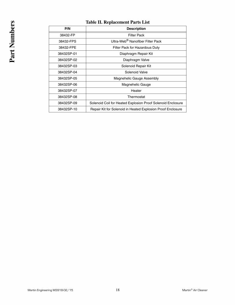
Table II. Replacement Parts ListP/N Description
38432-FP Filter Pack
38432-FPS Ultra-Web® Nanofiber Filter Pack
38432-FPE Filter Pack for Hazardous Duty
38432SP-01 Diaphragm Repair Kit
38432SP-02 Diaphragm Valve
38432SP-03 Solenoid Repair Kit
38432SP-04 Solenoid Valve
38432SP-05 Magnehelic Gauge Assembly
38432SP-06 Magnehelic Gauge
38432SP-07 Heater
38432SP-08 Thermostat
38432SP-09 Solenoid Coil for Heated Explosion Proof Solenoid Enclosure
38432SP-10 Repair Kit for Solenoid in Heated Explosion Proof Enclosure
Par
t N
umbe
rs

Martin Engineering M3918-02/15 19 Martin® Air Cleaner
Figure 12. Martin® Air Cleaner, P/N DFAC-10XXXXXX
1
2
3
4
5,6,7,8
9
10
11
12
13,14,15,16
17
18
19
22
23
24
26
27
28,29
30
31
3233
343536 40
37
38
39View with End Door
Section B–B
Enclosure Opening
Par
t N
umbe
rs
Martin Engineering M3918-02/15 20 Martin® Air Cleaner
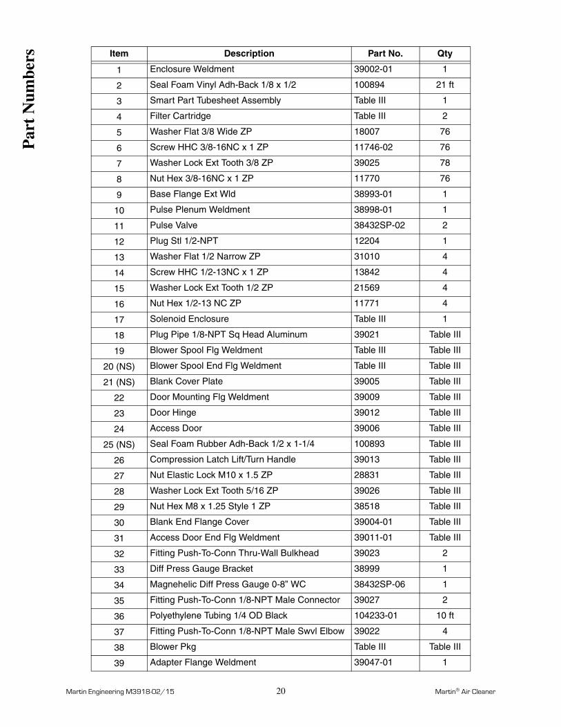
Item Description Part No. Qty
1 Enclosure Weldment 39002-01 1
2 Seal Foam Vinyl Adh-Back 1/8 x 1/2 100894 21 ft
3 Smart Part Tubesheet Assembly Table III 1
4 Filter Cartridge Table III 2
5 Washer Flat 3/8 Wide ZP 18007 76
6 Screw HHC 3/8-16NC x 1 ZP 11746-02 76
7 Washer Lock Ext Tooth 3/8 ZP 39025 78
8 Nut Hex 3/8-16NC x 1 ZP 11770 76
9 Base Flange Ext Wld 38993-01 1
10 Pulse Plenum Weldment 38998-01 1
11 Pulse Valve 38432SP-02 2
12 Plug Stl 1/2-NPT 12204 1
13 Washer Flat 1/2 Narrow ZP 31010 4
14 Screw HHC 1/2-13NC x 1 ZP 13842 4
15 Washer Lock Ext Tooth 1/2 ZP 21569 4
16 Nut Hex 1/2-13 NC ZP 11771 4
17 Solenoid Enclosure Table III 1
18 Plug Pipe 1/8-NPT Sq Head Aluminum 39021 Table III
19 Blower Spool Flg Weldment Table III Table III
20 (NS) Blower Spool End Flg Weldment Table III Table III
21 (NS) Blank Cover Plate 39005 Table III
22 Door Mounting Flg Weldment 39009 Table III
23 Door Hinge 39012 Table III
24 Access Door 39006 Table III
25 (NS) Seal Foam Rubber Adh-Back 1/2 x 1-1/4 100893 Table III
26 Compression Latch Lift/Turn Handle 39013 Table III
27 Nut Elastic Lock M10 x 1.5 ZP 28831 Table III
28 Washer Lock Ext Tooth 5/16 ZP 39026 Table III
29 Nut Hex M8 x 1.25 Style 1 ZP 38518 Table III
30 Blank End Flange Cover 39004-01 Table III
31 Access Door End Flg Weldment 39011-01 Table III
32 Fitting Push-To-Conn Thru-Wall Bulkhead 39023 2
33 Diff Press Gauge Bracket 38999 1
34 Magnehelic Diff Press Gauge 0-8” WC 38432SP-06 1
35 Fitting Push-To-Conn 1/8-NPT Male Connector 39027 2
36 Polyethylene Tubing 1/4 OD Black 104233-01 10 ft
37 Fitting Push-To-Conn 1/8-NPT Male Swvl Elbow 39022 4
38 Blower Pkg Table III Table III
39 Adapter Flange Weldment 39047-01 1
Par
t N
umbe
rs

Martin Engineering M3918-02/15 21 Martin® Air Cleaner
Table III. Martin® Air Cleaner Part Numbers and Quantities
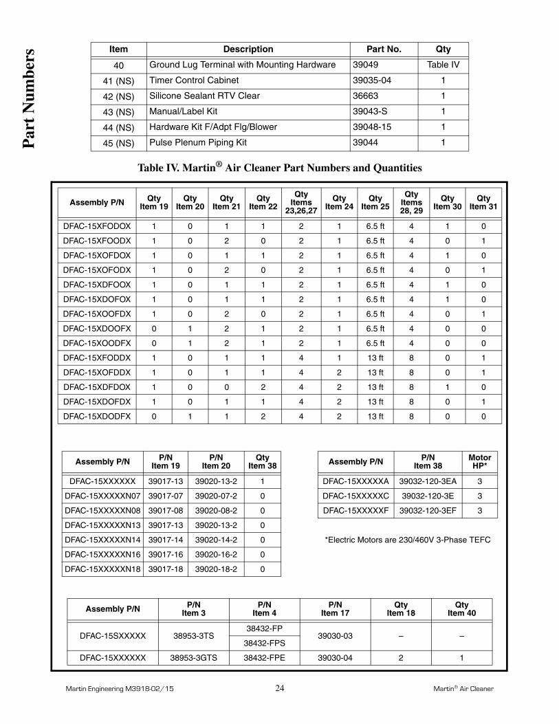
40 Ground Lug Terminal with Mounting Hardware 39049 Table III
41 (NS) Timer Control Cabinet 39035-04 1
42 (NS) Silicone Sealant RTV Clear 36663 1
43 (NS) Manual/Label Kit 39043-S 1
44 (NS) Hardware Kit F/Adpt Flg/Blower 39048-15 1
45 (NS) Pulse Plenum Piping Kit 39044 1
Assembly P/N QtyItem 19
QtyItem 20
QtyItem 21
QtyItem 22
QtyItems
23,26,27
QtyItem 24
QtyItem 25
QtyItems28, 29
QtyItem 30
QtyItem 31
DFAC-10XFODOX 1 0 1 1 2 1 6.5 ft 4 1 0
DFAC-10XFOODX 1 0 2 0 2 1 6.5 ft 4 0 1
DFAC-10XOFDOX 1 0 1 1 2 1 6.5 ft 4 1 0
DFAC-10XOFODX 1 0 2 0 2 1 6.5 ft 4 0 1
DFAC-10XDFOOX 1 0 1 1 2 1 6.5 ft 4 1 0
DFAC-10XDOFOX 1 0 1 1 2 1 6.5 ft 4 1 0
DFAC-10XOOFDX 1 0 2 0 2 1 6.5 ft 4 0 1
DFAC-10XDOOFX 0 1 2 1 2 1 6.5 ft 4 0 0
DFAC-10XOODFX 0 1 2 1 2 1 6.5 ft 4 0 0
DFAC-10XFODDX 1 0 1 1 4 1 13 ft 8 0 1
DFAC-10XOFDDX 1 0 1 1 4 2 13 ft 8 0 1
DFAC-10XDFDOX 1 0 0 2 4 2 13 ft 8 1 0
DFAC-10XDOFDX 1 0 1 1 4 2 13 ft 8 0 1
DFAC-10XDODFX 0 1 1 2 4 2 13 ft 8 0 0
Assembly P/N P/NItem 19
P/NItem 20
QtyItem 38 Assembly P/N P/N
Item 38MotorHP*
DFAC-10XXXXXX 39017-07 39020-07-2 1 DFAC-10XXXXXA 39031-12-3EA 3
DFAC-10XXXXXN07 39017-07 39020-07-2 0 DFAC-10XXXXXC 39031-12-3E 3
DFAC-10XXXXXN08 39017-08 39020-08-2 0 DFAC-10XXXXXF 39031-12-3EF 3
DFAC-10XXXXXN13 39017-13 39020-13-2 0
DFAC-10XXXXXN14 39017-14 39020-14-2 0 *Electric Motors are 230/460V 3-Phase TEFC
DFAC-10XXXXXN16 39017-16 39020-16-2 0
DFAC-10XXXXXN18 39017-18 39020-18-2 0
Assembly P/N P/NItem 3
P/NItem 4
P/NItem 17
QtyItem 18
QtyItem 40
DFAC-10SXXXXX 38953-2TS38432-FP
39030-03 – –38432-FPS
DFAC-10XXXXXX 38953-2GTS 38432-FPE 39030-04 4 1
Item Description Part No. Qty
Par
t N
umbe
rs

Martin Engineering M3918-02/15 22 Martin® Air Cleaner
Figure 13. Martin® Air Cleaner, P/N DFAC-15XXXXXX
26
19
31
39
9
30
28,2923
27
3
4
2
22
24
3433
117
10
12
11
13,14,15,16
35403632
18
5,6,7,8
37
38
View with End Door
Section B–B
Enclosure Opening
Par
t N
umbe
rs

Martin Engineering M3918-02/15 23 Martin® Air Cleaner
Item Description Part No. Qty
1 Enclosure Weldment 39002-02 1
2 Seal Foam Vinyl Adh-Back 1/8 x 1/2 100894 21 ft
3 Smart Part Tubesheet Assembly Table IV 1
4 Filter Cartridge Table IV 3
5 Washer Flat 3/8 Wide ZP 18007 86
6 Screw HHC 3/8-16NC x 1 ZP 11746-02 86
7 Washer Lock Ext Tooth 3/8 ZP 39025 88
8 Nut Hex 3/8-16NC x 1 ZP 11770 86
9 Base Flange Ext Wld 38993-02 1
10 Pulse Plenum Weldment 38998-02 1
11 Pulse Valve 38432SP-02 3
12 Plug Stl 1/2-NPT 12204 1
13 Washer Flat 1/2 Narrow ZP 31010 4
14 Screw HHC 1/2-13NC x 1 ZP 13842 4
15 Washer Lock Ext Tooth 1/2 ZP 21569 4
16 Nut Hex 1/2-13 NC ZP 11771 4
17 Solenoid Enclosure Table IV 1
18 Plug Pipe 1/8-NPT Sq Head Aluminum 39021 Table IV
19 Blower Spool Flg Weldment Table IV Table IV
20 (NS) Blower Spool End Flg Weldment Table IV Table IV
21 (NS) Blank Cover Plate 39005 Table IV
22 Door Mounting Flg Weldment 39009 Table IV
23 Door Hinge 39012 Table IV
24 Access Door 39006 Table IV
25 (NS) Seal Foam Rubber Adh-Back 1/2 x 1-1/4 100893 Table IV
26 Compression Latch Lift/Turn Handle 39013 Table IV
27 Nut Elastic Lock M10 x 1.5 ZP 28831 Table IV
28 Washer Lock Ext Tooth 5/16 ZP 39026 Table IV
29 Nut Hex M8 x 1.25 Style 1 ZP 38518 Table IV
30 Blank End Flange Cover 39004-02 Table IV
31 Access Door End Flg Weldment 39011-02 Table IV
32 Fitting Push-To-Conn Thru-Wall Bulkhead 39023 2
33 Diff Press Gauge Bracket 38999 1
34 Magnehelic Diff Press Gauge 0-8” WC 38432SP-06 1
35 Fitting Push-To-Conn 1/8-NPT Male Connector 39027 2
36 Polyethylene Tubing 1/4 OD Black 104233-01 14 ft
37 Fitting Push-To-Conn 1/8-NPT Male Swvl Elbow 39022 6
38 Blower Pkg Table IV Table IV
39 Adapter Flange Weldment 39047-02 1
Par
t N
umbe
rs
Martin Engineering M3918-02/15 24 Martin® Air Cleaner
Table IV. Martin® Air Cleaner Part Numbers and Quantities
40 Ground Lug Terminal with Mounting Hardware 39049 Table IV
41 (NS) Timer Control Cabinet 39035-04 1
42 (NS) Silicone Sealant RTV Clear 36663 1
43 (NS) Manual/Label Kit 39043-S 1
44 (NS) Hardware Kit F/Adpt Flg/Blower 39048-15 1
45 (NS) Pulse Plenum Piping Kit 39044 1
Assembly P/N QtyItem 19
QtyItem 20
QtyItem 21
QtyItem 22
QtyItems
23,26,27
QtyItem 24
QtyItem 25
QtyItems28, 29
QtyItem 30
QtyItem 31
DFAC-15XFODOX 1 0 1 1 2 1 6.5 ft 4 1 0
DFAC-15XFOODX 1 0 2 0 2 1 6.5 ft 4 0 1
DFAC-15XOFDOX 1 0 1 1 2 1 6.5 ft 4 1 0
DFAC-15XOFODX 1 0 2 0 2 1 6.5 ft 4 0 1
DFAC-15XDFOOX 1 0 1 1 2 1 6.5 ft 4 1 0
DFAC-15XDOFOX 1 0 1 1 2 1 6.5 ft 4 1 0
DFAC-15XOOFDX 1 0 2 0 2 1 6.5 ft 4 0 1
DFAC-15XDOOFX 0 1 2 1 2 1 6.5 ft 4 0 0
DFAC-15XOODFX 0 1 2 1 2 1 6.5 ft 4 0 0
DFAC-15XFODDX 1 0 1 1 4 1 13 ft 8 0 1
DFAC-15XOFDDX 1 0 1 1 4 2 13 ft 8 0 1
DFAC-15XDFDOX 1 0 0 2 4 2 13 ft 8 1 0
DFAC-15XDOFDX 1 0 1 1 4 2 13 ft 8 0 1
DFAC-15XDODFX 0 1 1 2 4 2 13 ft 8 0 0
Assembly P/N P/NItem 19
P/NItem 20
QtyItem 38 Assembly P/N P/N
Item 38MotorHP*
DFAC-15XXXXXX 39017-13 39020-13-2 1 DFAC-15XXXXXA 39032-120-3EA 3
DFAC-15XXXXXN07 39017-07 39020-07-2 0 DFAC-15XXXXXC 39032-120-3E 3
DFAC-15XXXXXN08 39017-08 39020-08-2 0 DFAC-15XXXXXF 39032-120-3EF 3
DFAC-15XXXXXN13 39017-13 39020-13-2 0
DFAC-15XXXXXN14 39017-14 39020-14-2 0 *Electric Motors are 230/460V 3-Phase TEFC
DFAC-15XXXXXN16 39017-16 39020-16-2 0
DFAC-15XXXXXN18 39017-18 39020-18-2 0
Assembly P/N P/NItem 3
P/NItem 4
P/NItem 17
QtyItem 18
QtyItem 40
DFAC-15SXXXXX 38953-3TS38432-FP
39030-03 – –38432-FPS
DFAC-15XXXXXX 38953-3GTS 38432-FPE 39030-04 2 1
Item Description Part No. Qty
Par
t N
umbe
rs
Martin Engineering M3918-02/15 25 Martin® Air Cleaner
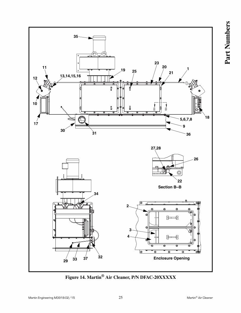
Figure 14. Martin® Air Cleaner, P/N DFAC-20XXXXX
4
3
2
29 33 37 32
34
22
26
27,28
18
36
9
5,6,7,8
121
2023
2519
35
3130
17
10
12
11
13,14,15,16
Section B–B
Enclosure Opening
Par
t N
umbe
rs
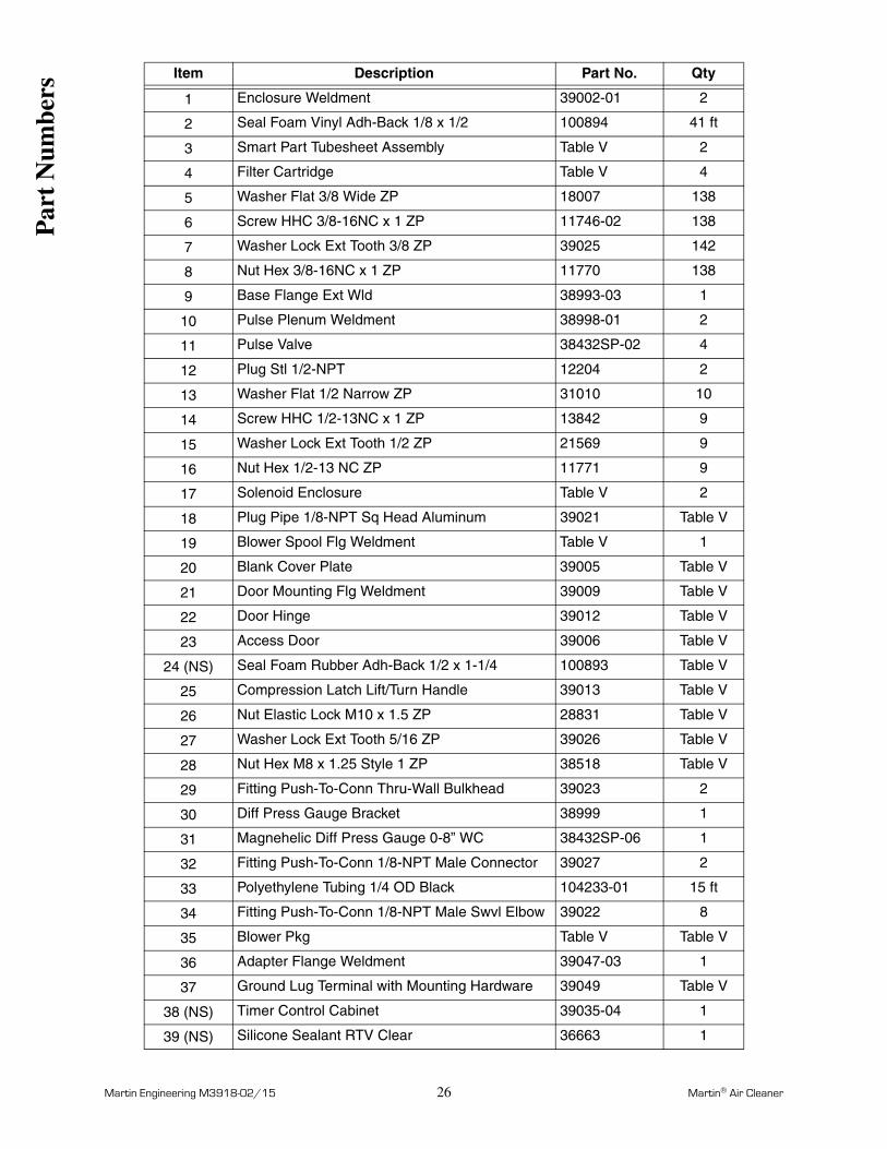
Martin Engineering M3918-02/15 26 Martin® Air Cleaner
Item Description Part No. Qty
1 Enclosure Weldment 39002-01 2
2 Seal Foam Vinyl Adh-Back 1/8 x 1/2 100894 41 ft
3 Smart Part Tubesheet Assembly Table V 2
4 Filter Cartridge Table V 4
5 Washer Flat 3/8 Wide ZP 18007 138
6 Screw HHC 3/8-16NC x 1 ZP 11746-02 138
7 Washer Lock Ext Tooth 3/8 ZP 39025 142
8 Nut Hex 3/8-16NC x 1 ZP 11770 138
9 Base Flange Ext Wld 38993-03 1
10 Pulse Plenum Weldment 38998-01 2
11 Pulse Valve 38432SP-02 4
12 Plug Stl 1/2-NPT 12204 2
13 Washer Flat 1/2 Narrow ZP 31010 10
14 Screw HHC 1/2-13NC x 1 ZP 13842 9
15 Washer Lock Ext Tooth 1/2 ZP 21569 9
16 Nut Hex 1/2-13 NC ZP 11771 9
17 Solenoid Enclosure Table V 2
18 Plug Pipe 1/8-NPT Sq Head Aluminum 39021 Table V
19 Blower Spool Flg Weldment Table V 1
20 Blank Cover Plate 39005 Table V
21 Door Mounting Flg Weldment 39009 Table V
22 Door Hinge 39012 Table V
23 Access Door 39006 Table V
24 (NS) Seal Foam Rubber Adh-Back 1/2 x 1-1/4 100893 Table V
25 Compression Latch Lift/Turn Handle 39013 Table V
26 Nut Elastic Lock M10 x 1.5 ZP 28831 Table V
27 Washer Lock Ext Tooth 5/16 ZP 39026 Table V
28 Nut Hex M8 x 1.25 Style 1 ZP 38518 Table V
29 Fitting Push-To-Conn Thru-Wall Bulkhead 39023 2
30 Diff Press Gauge Bracket 38999 1
31 Magnehelic Diff Press Gauge 0-8” WC 38432SP-06 1
32 Fitting Push-To-Conn 1/8-NPT Male Connector 39027 2
33 Polyethylene Tubing 1/4 OD Black 104233-01 15 ft
34 Fitting Push-To-Conn 1/8-NPT Male Swvl Elbow 39022 8
35 Blower Pkg Table V Table V
36 Adapter Flange Weldment 39047-03 1
37 Ground Lug Terminal with Mounting Hardware 39049 Table V
38 (NS) Timer Control Cabinet 39035-04 1
39 (NS) Silicone Sealant RTV Clear 36663 1
Par
t N
umbe
rs
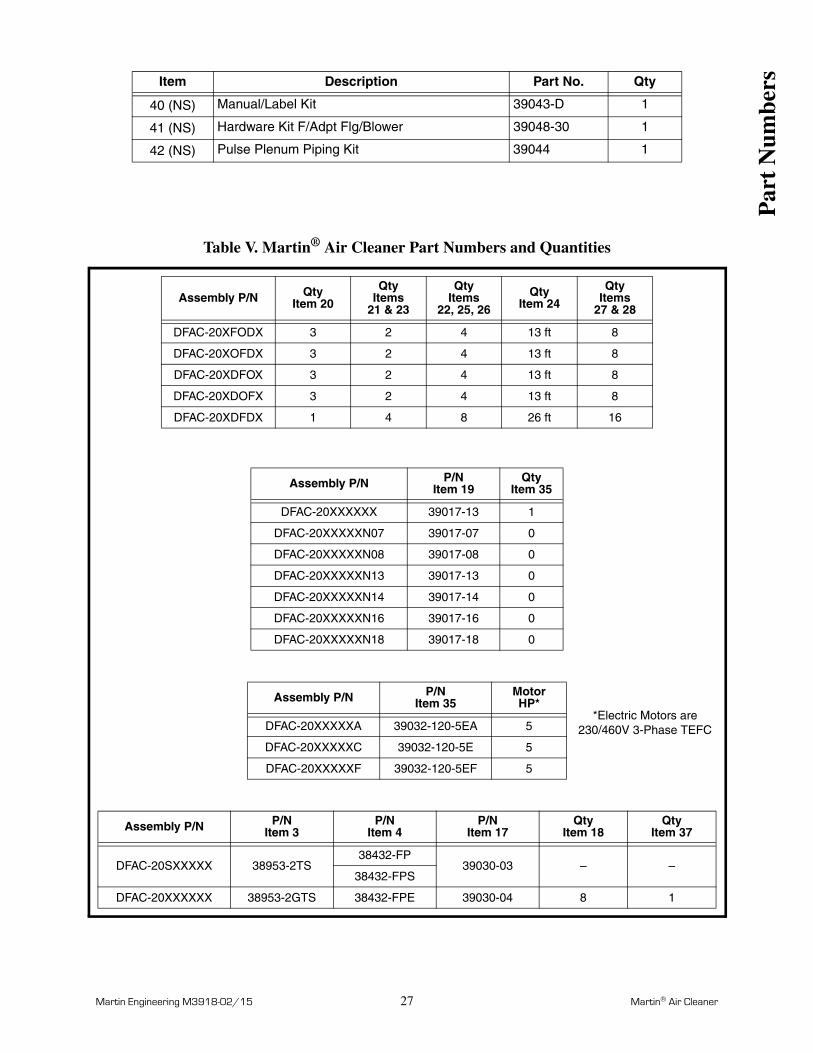
Martin Engineering M3918-02/15 27 Martin® Air Cleaner
Table V. Martin® Air Cleaner Part Numbers and Quantities
40 (NS) Manual/Label Kit 39043-D 1
41 (NS) Hardware Kit F/Adpt Flg/Blower 39048-30 1
42 (NS) Pulse Plenum Piping Kit 39044 1
Assembly P/N QtyItem 20
QtyItems
21 & 23
QtyItems
22, 25, 26
QtyItem 24
QtyItems
27 & 28
DFAC-20XFODX 3 2 4 13 ft 8
DFAC-20XOFDX 3 2 4 13 ft 8
DFAC-20XDFOX 3 2 4 13 ft 8
DFAC-20XDOFX 3 2 4 13 ft 8
DFAC-20XDFDX 1 4 8 26 ft 16
Assembly P/N P/NItem 19
QtyItem 35
DFAC-20XXXXXX 39017-13 1
DFAC-20XXXXXN07 39017-07 0
DFAC-20XXXXXN08 39017-08 0
DFAC-20XXXXXN13 39017-13 0
DFAC-20XXXXXN14 39017-14 0
DFAC-20XXXXXN16 39017-16 0
DFAC-20XXXXXN18 39017-18 0
Assembly P/N P/NItem 35
MotorHP*
DFAC-20XXXXXA 39032-120-5EA 5
DFAC-20XXXXXC 39032-120-5E 5
DFAC-20XXXXXF 39032-120-5EF 5
Assembly P/N P/NItem 3
P/NItem 4
P/NItem 17
QtyItem 18
QtyItem 37
DFAC-20SXXXXX 38953-2TS38432-FP
39030-03 – –38432-FPS
DFAC-20XXXXXX 38953-2GTS 38432-FPE 39030-04 8 1
Item Description Part No. Qty
Par
t N
umbe
rs
*Electric Motors are 230/460V 3-Phase TEFC
Martin Engineering M3918-02/15 28 Martin® Air Cleaner
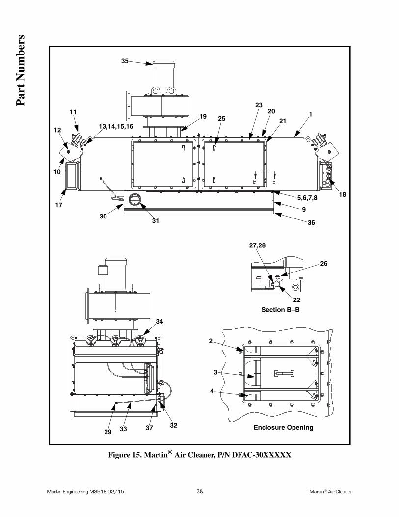
Figure 15. Martin® Air Cleaner, P/N DFAC-30XXXXX
4
3
2
29 33 37 32
34
22
26
27,28
18
36
9
5,6,7,8
121
2023
2519
35
3130
17
10
12
11
13,14,15,16
Section B–B
Enclosure Opening
Par
t N
umbe
rs
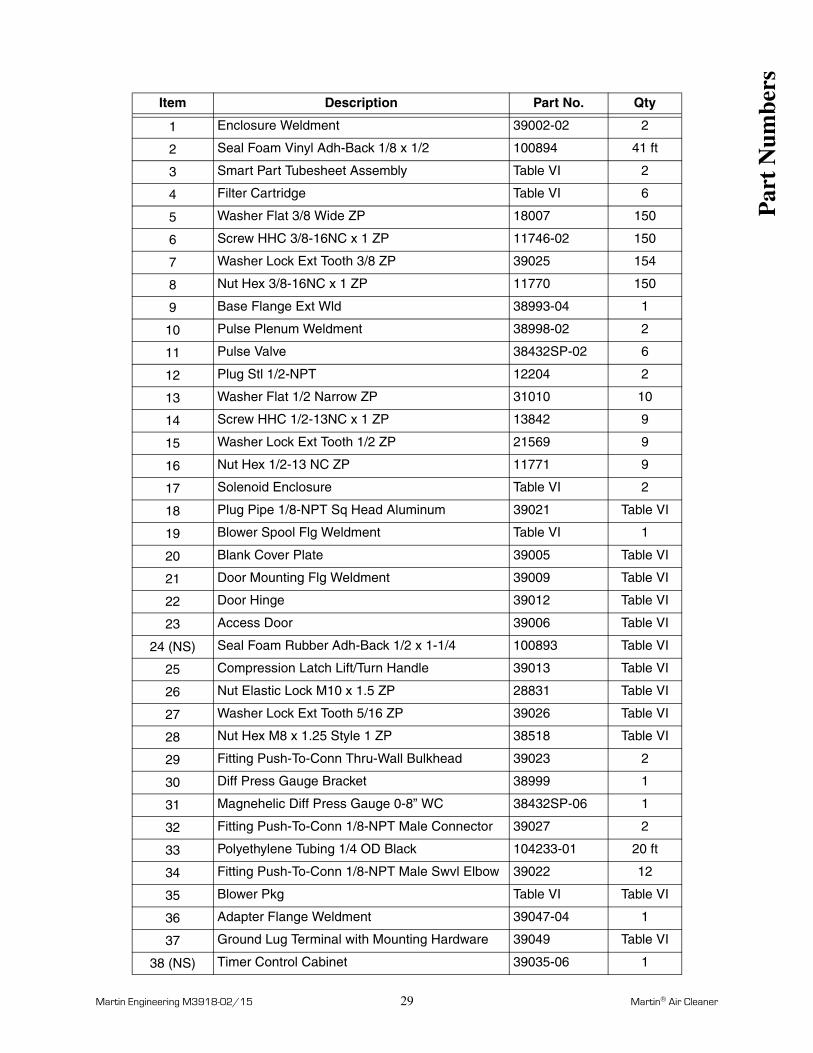
Martin Engineering M3918-02/15 29 Martin® Air Cleaner
Item Description Part No. Qty
1 Enclosure Weldment 39002-02 2
2 Seal Foam Vinyl Adh-Back 1/8 x 1/2 100894 41 ft
3 Smart Part Tubesheet Assembly Table VI 2
4 Filter Cartridge Table VI 6
5 Washer Flat 3/8 Wide ZP 18007 150
6 Screw HHC 3/8-16NC x 1 ZP 11746-02 150
7 Washer Lock Ext Tooth 3/8 ZP 39025 154
8 Nut Hex 3/8-16NC x 1 ZP 11770 150
9 Base Flange Ext Wld 38993-04 1
10 Pulse Plenum Weldment 38998-02 2
11 Pulse Valve 38432SP-02 6
12 Plug Stl 1/2-NPT 12204 2
13 Washer Flat 1/2 Narrow ZP 31010 10
14 Screw HHC 1/2-13NC x 1 ZP 13842 9
15 Washer Lock Ext Tooth 1/2 ZP 21569 9
16 Nut Hex 1/2-13 NC ZP 11771 9
17 Solenoid Enclosure Table VI 2
18 Plug Pipe 1/8-NPT Sq Head Aluminum 39021 Table VI
19 Blower Spool Flg Weldment Table VI 1
20 Blank Cover Plate 39005 Table VI
21 Door Mounting Flg Weldment 39009 Table VI
22 Door Hinge 39012 Table VI
23 Access Door 39006 Table VI
24 (NS) Seal Foam Rubber Adh-Back 1/2 x 1-1/4 100893 Table VI
25 Compression Latch Lift/Turn Handle 39013 Table VI
26 Nut Elastic Lock M10 x 1.5 ZP 28831 Table VI
27 Washer Lock Ext Tooth 5/16 ZP 39026 Table VI
28 Nut Hex M8 x 1.25 Style 1 ZP 38518 Table VI
29 Fitting Push-To-Conn Thru-Wall Bulkhead 39023 2
30 Diff Press Gauge Bracket 38999 1
31 Magnehelic Diff Press Gauge 0-8” WC 38432SP-06 1
32 Fitting Push-To-Conn 1/8-NPT Male Connector 39027 2
33 Polyethylene Tubing 1/4 OD Black 104233-01 20 ft
34 Fitting Push-To-Conn 1/8-NPT Male Swvl Elbow 39022 12
35 Blower Pkg Table VI Table VI
36 Adapter Flange Weldment 39047-04 1
37 Ground Lug Terminal with Mounting Hardware 39049 Table VI
38 (NS) Timer Control Cabinet 39035-06 1
Par
t N
umbe
rs
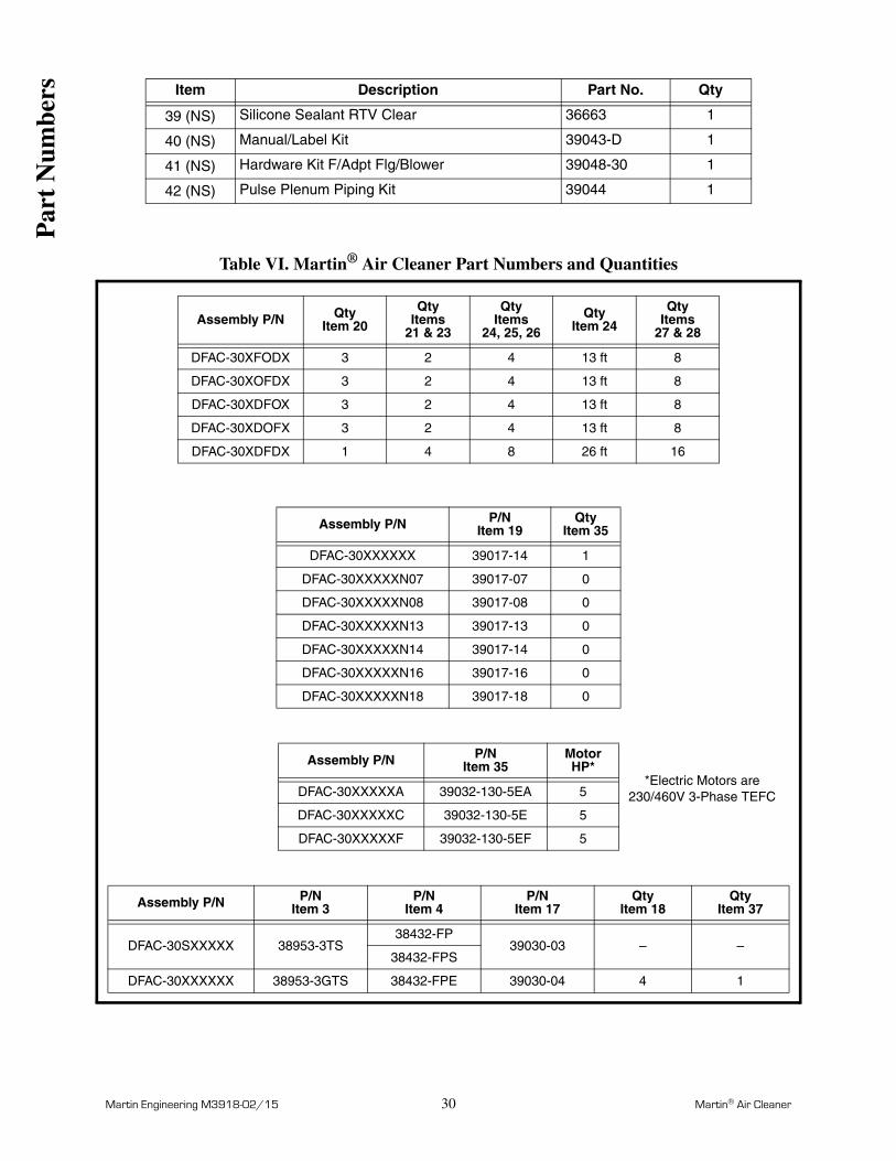
Martin Engineering M3918-02/15 30 Martin® Air Cleaner
Table VI. Martin® Air Cleaner Part Numbers and Quantities
39 (NS) Silicone Sealant RTV Clear 36663 1
40 (NS) Manual/Label Kit 39043-D 1
41 (NS) Hardware Kit F/Adpt Flg/Blower 39048-30 1
42 (NS) Pulse Plenum Piping Kit 39044 1
Assembly P/N QtyItem 20
QtyItems
21 & 23
QtyItems
24, 25, 26
QtyItem 24
QtyItems
27 & 28
DFAC-30XFODX 3 2 4 13 ft 8
DFAC-30XOFDX 3 2 4 13 ft 8
DFAC-30XDFOX 3 2 4 13 ft 8
DFAC-30XDOFX 3 2 4 13 ft 8
DFAC-30XDFDX 1 4 8 26 ft 16
Assembly P/N P/NItem 19
QtyItem 35
DFAC-30XXXXXX 39017-14 1
DFAC-30XXXXXN07 39017-07 0
DFAC-30XXXXXN08 39017-08 0
DFAC-30XXXXXN13 39017-13 0
DFAC-30XXXXXN14 39017-14 0
DFAC-30XXXXXN16 39017-16 0
DFAC-30XXXXXN18 39017-18 0
Assembly P/N P/NItem 35
MotorHP*
DFAC-30XXXXXA 39032-130-5EA 5
DFAC-30XXXXXC 39032-130-5E 5
DFAC-30XXXXXF 39032-130-5EF 5
Assembly P/N P/NItem 3
P/NItem 4
P/NItem 17
QtyItem 18
QtyItem 37
DFAC-30SXXXXX 38953-3TS38432-FP
39030-03 – –38432-FPS
DFAC-30XXXXXX 38953-3GTS 38432-FPE 39030-04 4 1
Item Description Part No. Qty
Par
t N
umbe
rs
*Electric Motors are 230/460V 3-Phase TEFC


Form No. M3918-02/15 © Martin Engineering Company 2012, 2015