Embed Size (px)
Citation preview
PRODUCT GUIDE
Structural, Fire and Acoustic Victoria
Masonry Blocks & Bricks
2
Structural, Fire and AcousticMASONRY BLOCKS AND BRICKS
Product Disclaimer: Concrete Blocks, Bricks, Pavers and Retaining Wall products supplied by National Masonry® are manufactured using raw materials that inherently vary in nature. Whilst all effort is made to produce uniformity in our range of products, variation in colour, texture, and finish can be present. The dimensional characteristics of all products are nominal and variations in length, height, and width can occur from unit to unit which needs to be taken into consideration when installing these products.
About National Masonry®
National Masonry® has quickly established itself as the industry leader with exceptional product quality and outstanding customer service with a clear vision of customers for life. We are obsessed with ensuring every customer has a memorable experience with us and to leave you with no doubt that you have made the right choice.
National Masonry®, the new benchmark in masonry.
Pallet ReturnAll pallets remain the property of National Masonry®
NATIONAL MASONRYCall to Arrange Pickup
Call your local branch during office hours.
(03) 9361 6443 or (03) 9361 6400
Online Booking Pickup
Use our Pallet Collection Form on our website.
www.nationalmasonry.com.au
2
Products Overview ....................................................................................... 4
National Masonry® Construction Solutions .................................................. 4
What’s in this Guide .................................................................................. 4
Additional Assistance and Information ........................................................ 4
National Masonry® Products ......................................................................... 4
Planning and Design .................................................................................... 5
Introduction to the Structural Design of Masonry ......................................... 5
Robustness of Walls .................................................................................. 5
Robustness of Isolated Piers ...................................................................... 5
Strength ................................................................................................... 6
Bending .................................................................................................... 6
Shear ....................................................................................................... 6
Durability .................................................................................................. 6
Movement ................................................................................................ 7
External Control Joints ............................................................................... 7
Internal Control Joints .............................................................................. 7
Energy Efficiency for Buildings in Victoria .................................................. 7
R-Values for Typical Wall Construction ........................................................ 7
Design of Core Filled and Steel Reinforced Masonry Retaining Walls ........... 8
Construction Recommendations ................................................................. 8
Reinforced Masonry Lintels ........................................................................ 9
Moment and Shear Capacities for Series 200 Blocks (190mm leaf) ............. 9
Backfill Drainage .................................................................................... 10
Structural Design Guidelines ................................................................... 10
Fire Design ................................................................................................ 17
Masonry Design for Fire Resistance ........................................................ 17
Masonry Design for Structural Adequacy FRL .......................................... 17
Masonry Design for Integrity FRL ............................................................ 17
Effect of Chases on Fire Rated Masonry .................................................. 18
How to Select National Masonry® Units for Fire Rated Walls ..................... 18
Material Attributes (Victoria) .................................................................... 18
National Masonry® Structural Adequacy Selection Graphs and Tables ....... 20
Scoria Blend (SB) High Fire Rated Block — Srf = 22.6 ............................. 21
Scoria Blend (SB) High Fire Rated Block - Srf = 21.5 ................................ 22
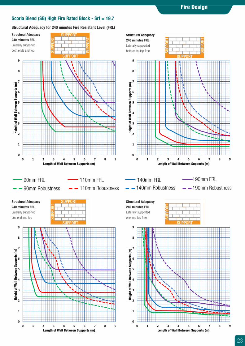
Scoria Blend (SB) High Fire Rated Block - Srf = 19.7 ................................ 23
Ash Grey (AG) - Basalt > 45% - Srf = 22.5 ............................................. 24
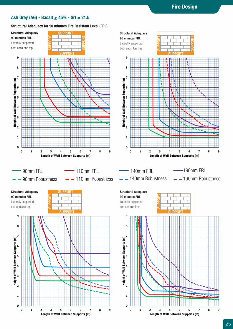
Ash Grey (AG) - Basalt > 45% - Srf = 21.5 ............................................. 25
Designer Range - Srf = 18.0 ................................................................... 26
Designer Range - Srf = 17.0 ................................................................... 27
Reinforced Masonry Walls ....................................................................... 28
Walls Restrained at Top (Unrestrained Ends) ............................................. 29
Acoustic Design ......................................................................................... 30
Acoustic Performance Ratings ................................................................. 30
Masonry with Plasterboard Systems ......................................................... 30
Masonry with Plasterboard on Furring Channels ....................................... 30
Masonry with Plasterboard on Stud Framing ............................................. 30
Designing Masonry Walls for Acoustic Performance .................................. 30
Sound Insulation ..................................................................................... 30
Guidelines for Optimum Performance ....................................................... 31
Acoustic Performance On-Site ................................................................. 32
Acoustic Systems....................................................................................... 33
Rw+Ctr Masonry Walls ............................................................................ 33
STC and Acoustic Systems Data with Lining Systems ................................ 33
Fire Rated Block - Scoria Blend .............................................................. 34
Ash Grey Block (AG) Standard & Core Fill ................................................. 35
Scoria Quick Brick FR (SB) ...................................................................... 36
USG Boral Acoustic Upgrades - Internal Walls ........................................... 37
USG Boral Acoustic Upgrades - Shaft/Stair Walls ...................................... 39
Contents
3
4
National Masonry® Construction SolutionsNational Masonry® offers a comprehensive range of proven products and systems including Masonry Blocks, Masonry Bricks, Fire and Acoustic Wall Systems, Segmental Block Retaining Walls and Segmental Paving Products.
What’s in this GuideNational Masonry® Structural, Fire and Acoustic guide (this book), provides a summary of important design information for structural, fire and acoustic masonry applications and an extensive range of fire and/or acoustic systems to cater for many design scenarios.
Planning & Design SectionDesign issues relevant to the selection of Natural Masonry products for structural adequacy, based on appropriate wall design criteria.
Fire Design Section
The relevant design processes for the selection of National Masonry® Products for fire rated applications. The fire resistance performance of National Masonry® concrete blocks is determined as per AS3700 : 2018 Section 6. This section includes a step-by-step selection guide and a series of selection graphs which can greatly speed up the preliminary selection and comparison of suitable designs and products.
Acoustic Design SectionA brief overview of acoustic rating methods, relevant considerations for acoustic design and guidelines for good acoustic design and detailing methods.
Acoustic Systems Section
Provides an extensive range of fire and acoustic wall system solutions supported by test results and acoustic performance estimates.
Please Note:This guide has been prepared as a comprehensive Product Reference Guide. It does not attempt to cover all the requirements of the Codes and Standards which apply to masonry construction for structural, fire or acoustic applications. All structural, fire and acoustic detailing should be checked and approved by appropriately qualified engineers before construction. National Masonry® reserves the right to change the contents of this guide without notice.
This guide is based on products available at the time of publication from the National Masonry® Victoria sales region. Different products and specifications may apply to National Masonry® products sourced from other regions..
Additional Assistance and Information• Contact Details: Please refer to the outside back cover of this publication for
National Masonry® contact details.• Colour and Texture Variation: The supply of raw materials can vary over time. In
addition, variation can occur between product types and production batches. Also please recognise that the printed colours in this brochure are only a guide. Please, always ask to see a sample of your colour/texture choice before specifying or ordering.
• Terms and Conditions of Sale: For a full set of Terms and Conditions of Sale please contact your nearest National Masonry® sales office.
For technical support and sales office details please refer to the outside back cover.
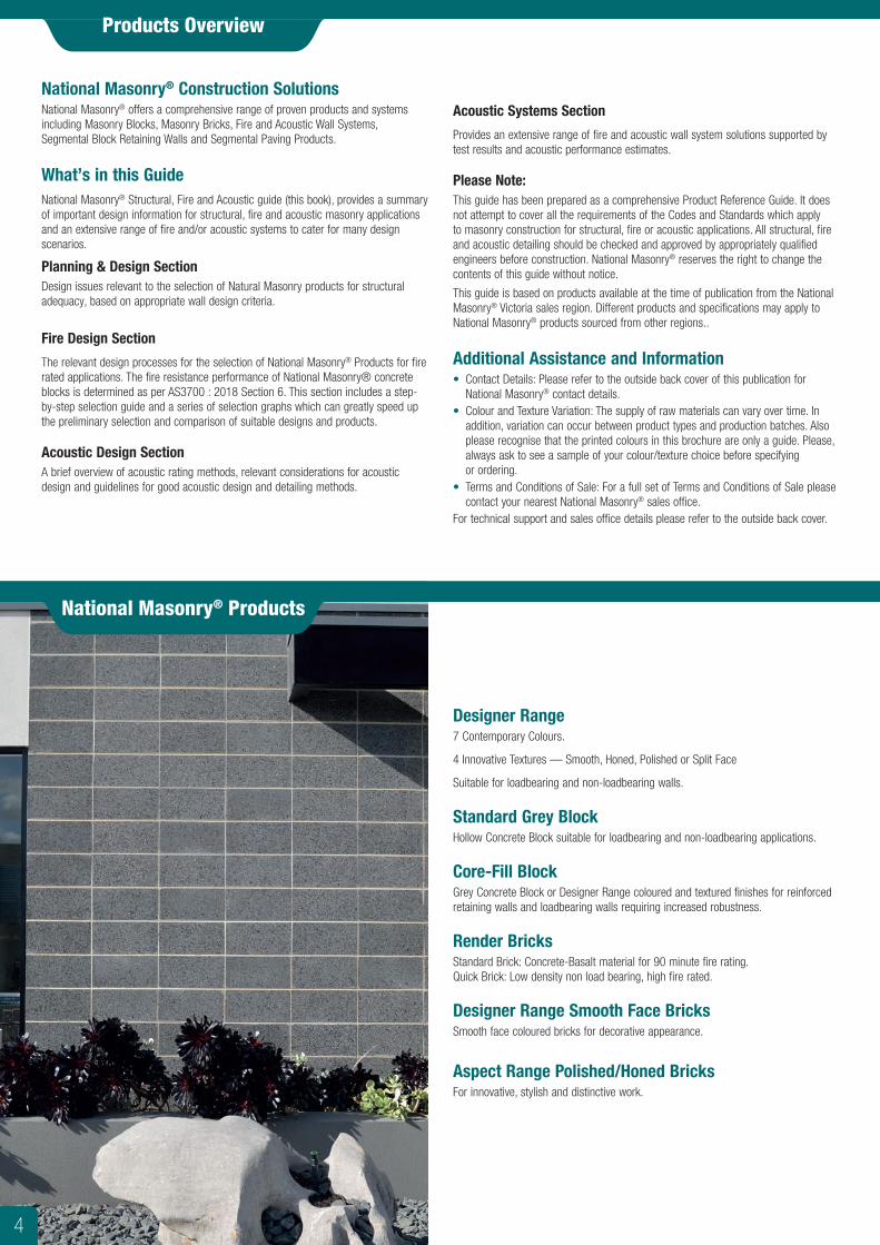
Designer Range7 Contemporary Colours.
4 Innovative Textures — Smooth, Honed, Polished or Split Face
Suitable for loadbearing and non-loadbearing walls.
Standard Grey BlockHollow Concrete Block suitable for loadbearing and non-loadbearing applications.
Core-Fill BlockGrey Concrete Block or Designer Range coloured and textured finishes for reinforced retaining walls and loadbearing walls requiring increased robustness.
Render BricksStandard Brick: Concrete-Basalt material for 90 minute fire rating. Quick Brick: Low density non load bearing, high fire rated.
Designer Range Smooth Face Bricks Smooth face coloured bricks for decorative appearance.
Aspect Range Polished/Honed BricksFor innovative, stylish and distinctive work.
Products Overview
National Masonry® Products
4
Planning and Design
Introduction to the Structural Design of Masonry The following design information is based on Australian Standard AS3700:2018 Masonry Structures. Reference to ‘Clauses’ and ‘Formulae’ are those used in AS3700. This information is provided as a guide only to the processes involved in designing masonry. All masonry should be designed by a suitably qualified structural engineer.
Robustness of WallsWalls are to have an adequate degree of Robustness proportioned to resist an ultimate uniformly distributed load of 0.5 kPa as outlined and referenced in AS3700: 2018 Clause 4.6.2.
The minimum design requirement may be overridden by Fire, Wind, Snow, Earthquake, Live and Dead Load requirements.
Should the initial product/design chosen not provide a suitable solution, then a thicker National masonry product more suited to the application should be evaluated, or alternatively, add extra restraints or reinforcement.
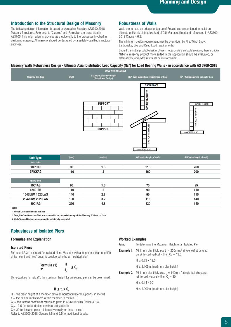
Masonry Walls Robustness Design - Ultimate Axial Distributed Load Capacity (Nc*) for Load Bearing Walls - in accordance with AS 3700-2018 WALL WITH FREE ENDS
Masonry Unit Type Width Maximum Allowable Height (Robustness Design) Nc*- Wall supporting Timber Floor or Roof Nc*- Wall supporting Concrete Slab
Unit Type (mm) (metres) (kN/metre length of wall) (kN/metre length of wall)
Solid Units
1031DR 90 1.6 210 260BRICKAG 110 2 160 200
Hollow Units
1001AG 90 1.6 75 9512401FR 110 2 90 110
1542UNV, 1520LWS 140 2.3 95 1152042UNV, 2020LWS 190 3.2 115 140
3001AG 290 4.8 120 140Notes
1. Mortar Class assumed as Min M3
2. Floor, Roof and Concrete Slab are assumed to be supported on top of the Masonry Wall not on face
3. Walls Top and Bottom are assumed to be laterally supported
Formulae and Explanation
Isolated Piers Formula 4.6.3 (1) is used for isolated piers. Masonry with a length less than one fifth of its height and ‘free’ ends, is considered to be an ‘isolated pier’.
Formula (1) is:
H≤ Cvtr
By re-working formula (1), the maximum height for an isolated pier can be determined:
H ≤ tr x Cv
H = the clear height of a member between horizontal lateral supports, in metrestr = the minimum thickness of the member, in metres Cv = robustness coefficient, values as given in AS3700:2018 Clause 4.6.3 Cv= 13.5 for isolated piers unreinforced verticallyCv= 30 for isolated piers reinforced vertically or pres-tressedRefer to AS3700:2018 Clauses 8.6 and 9.5 for additional details.
Worked Examples Aim: To determine the Maximum Height of an Isolated Pier
Example 1: Minimum pier thickness tr = 230mm A single leaf structure, unreinforced vertically, then Cv = 13.5
H ≤ 0.23 x 13.5
H ≤ 3.105m (maximum pier height)
Example 2: Minimum pier thickness, tr = 140mm A single leaf structure, reinforced, vertically then Cv = 30
H ≤ 0.14 x 30
H ≤ 4.200m (maximum pier height)
Robustness of Isolated Piers
SUPPORT
SUPPORT
5
Planning and Design
StrengthCompressive strength is resistance to load, measured by the amount of pressure to crush a masonry unit. The pressure, usually measured in megapascals (MPa), is the force in kilonewtons (kN) x 1000, divided by the loaded area in square mm.
Unconfined compressive strength is compressive strength, multiplied by an aspect ratio, Ka (see AS4456.4, Table 1). The unit height divided by its thickness is used to determine the aspect ratio.
A solid brick will give a lower compressive strength if crushed on its end rather than on its flat, as normally laid. In theory, the aspect ratio will convert both tests to the same unconfined compressive strength.
The strength of hollow blocks is calculated by dividing the force by the face shells only. A 90mm hollow and 90mm solid block are both 10MPa, but since the area of the face shells on the hollow block is about half the area of the solid block, the hollow will only carry half the load of the solid.
Characteristic Unconfined Compressive Strength of masonry UNITS is ƒ ’ uc.ƒ ’uc is the average of crushing forces divided by loaded areas, multiplied by the aspect ratio, minus the standard deviation x 1.65.
Characteristic Compressive Strength of a masonry WALL is ƒ ’ m.ƒ ’m is the square root of ƒ ’uc, multiplied by Km (a mortar strength factor), multiplied by Kh (a factor for the amount of mortar joints) as per AS3700, 3.3.2.
The Km factor is 1.4 for M3 mortar on solid and cored units and is 1.6 for the face shells of hollow units. For the richer M4 mortar it is 1.5 (Table 3.1).
The Kh factor is 1 for 76mm high units with 10mm mortar beds and is 1.3 for 190mm units with 10mm mortar beds.
In other words, a wall of 190mm high units is 30% stronger than a wall of 76mm high units of the same ƒ ’uc.
Bending
Characteristic Flexural Tensile Strength is ƒ ’ mt. Masonry is good in compression but poor in tension. Mortar joint strength is generally zero or 0.2MPa for loads from wind, earthquake etc. Higher bending forces may require masonry to be partially reinforced.
Shear
Characteristic Shear Strength is ƒ ’ ms.At damp course, it is zero unless tested. Elsewhere, mortar joints have ƒ ’ms values of between 0.15 and 0.35MPa.
As with tension, high shear loads may require partially reinforced masonry.
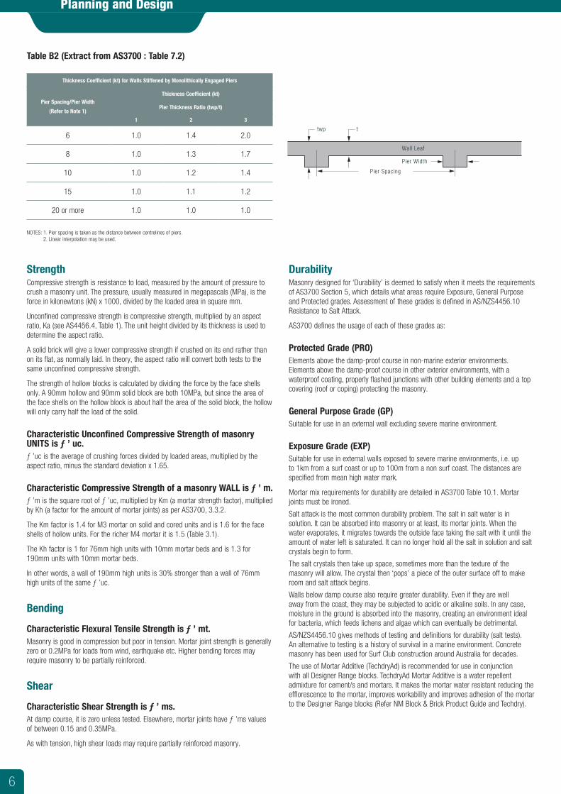
Table B2 (Extract from AS3700 : Table 7.2)
Thickness Coefficient (kt) for Walls Stiffened by Monolithically Engaged Piers
Pier Spacing/Pier Width
(Refer to Note 1)
Thickness Coefficient (kt)
Pier Thickness Ratio (twp/t)
1 2 3
6 1.0 1.4 2.0
8 1.0 1.3 1.7
10 1.0 1.2 1.4
15 1.0 1.1 1.2
20 or more 1.0 1.0 1.0
NOTES: 1. Pier spacing is taken as the distance between centrelines of piers. 2. Linear interpolation may be used.
Pier Spacing
Pier Width
Wall Leaf
twp t
DurabilityMasonry designed for ‘Durability’ is deemed to satisfy when it meets the requirements of AS3700 Section 5, which details what areas require Exposure, General Purpose and Protected grades. Assessment of these grades is defined in AS/NZS4456.10 Resistance to Salt Attack.
AS3700 defines the usage of each of these grades as:
Protected Grade (PRO)Elements above the damp-proof course in non-marine exterior environments. Elements above the damp-proof course in other exterior environments, with a waterproof coating, properly flashed junctions with other building elements and a top covering (roof or coping) protecting the masonry.
General Purpose Grade (GP)Suitable for use in an external wall excluding severe marine environment.
Exposure Grade (EXP)Suitable for use in external walls exposed to severe marine environments, i.e. up to 1km from a surf coast or up to 100m from a non surf coast. The distances are specified from mean high water mark.
Mortar mix requirements for durability are detailed in AS3700 Table 10.1. Mortar joints must be ironed.
Salt attack is the most common durability problem. The salt in salt water is in solution. It can be absorbed into masonry or at least, its mortar joints. When the water evaporates, it migrates towards the outside face taking the salt with it until the amount of water left is saturated. It can no longer hold all the salt in solution and salt crystals begin to form.
The salt crystals then take up space, sometimes more than the texture of the masonry will allow. The crystal then ‘pops’ a piece of the outer surface off to make room and salt attack begins.
Walls below damp course also require greater durability. Even if they are well away from the coast, they may be subjected to acidic or alkaline soils. In any case, moisture in the ground is absorbed into the masonry, creating an environment ideal for bacteria, which feeds lichens and algae which can eventually be detrimental.
AS/NZS4456.10 gives methods of testing and definitions for durability (salt tests). An alternative to testing is a history of survival in a marine environment. Concrete masonry has been used for Surf Club construction around Australia for decades.
The use of Mortar Additive (TechdryAd) is recommended for use in conjunction with all Designer Range blocks. TechdryAd Mortar Additive is a water repellent admixture for cement/s and mortars. It makes the mortar water resistant reducing the efflorescence to the mortar, improves workability and improves adhesion of the mortar to the Designer Range blocks (Refer NM Block & Brick Product Guide and Techdry).
6
Planning and Design
MovementIn general, concrete units contract as they cure while clay units will expand. They both expand as they take up water and contract as they dry. They both expand as they get hot and contract as they cool.
Curing Movement in Concrete UnitsAS/NZS4456.12 gives methods for determining coefficients of curing contraction and coefficients of drying contraction for concrete units.
Drying ContractionThe drying contraction test on masonry units is an indication of their maximum amount of movement from totally saturated to ambient dry. A typical result is 0.5mm/m but can be as high as 1mm/m for lightweight units that are more absorptive. For example, a drying contraction of 0.5mm/m, in an 8m panel of masonry, has the potential to shrink 4mm from saturated condition to dry.
External Control JointsAS3700, Clause 4.8 requires control joint spacing to limit panel movement to:
• 10mm maximum for opening of control joints (4.8.2.2b)• 15mm maximum for closing of control joints (4.8.3.2 b)• 5mm minimum when closed (4.8.3.2 c)Because of temperature variations and the shrinkage in a concrete masonry wall construction, it is necessary to provide control joints in blockwork at a maximum spacing of 6m and at points of potential cracking e.g. beside openings and at large steps in wall or footing.
Spacing should be measured around corners, not from corners. Ideally, the control joint is located near the corner, concealed behind a down pipe.
External control joints should be finished with a flexible sealant.
Control joints create a ‘free end’ in terms of ‘robustness’ and FRLs for structural adequacy, so their positioning is critical to the overall design of the structure.
In portal frame construction, the control joint is positioned at a column so that both ends can be tied to the column flanges. The mason and renderer must keep the control joint clean, otherwise, bridging mortar or render will induce cracks from those points as the masonry moves. If ties are used over control joints, they must be sleeved to allow movement.
Adding extra cement to mortar or render causes more shrinkage. Some Lightweight units can be as low as 5MPa, so are susceptible to cracking if laid in rich mortar or rendered with a cement-rich mix.
Internal Control JointsThe spacing of internal control joints for concrete units is recommended at 5.5m minimum.
Energy Efficiency for Buildings in Victoria
Basic Information guided by NCC 2019 Building Code of Australia (BCA) Volume 1 and Volume 2(Reference website: http://www.abcb.gov.au/)Buildings fall into Different Building Classifications from 1 to 10 as defined at: https://www.vba.vic.gov.au/building/regulatory-framework/building-classes.
In Victoria the Thermal Design Climate Zones are 4,6 and 7 as per locations listed in NCC 2019 Building Code of Australia Page 646.
The minimum wall R value requirements for different Climate Zones can be assessed in J1.5a Vol 1 NCC 2019 Page 369 for Class 2 to 9 Buildings.
Vol 2 NCC 2019 provides the requirements for Class 1 and Class 10a,b,c Buildings.
Table 2a on Page 388 0f Vol 1 NCC 2019 lists the thermal conductivities of concrete blocks.
The R-Value (thermal resistance, Kelvin square meters per watt, K.m2/W) of a material can be determined by dividing the thickness of the material in metres by the thermal conductivity in W/m.K.
Total R-Value means the sum of R values of wall components including air spaces and associated surfaces.
Masonry R-Values (Typical)• 90mm hollow (10.01) = 0.09• 110mm bricks = 0.12• 140mm hollow (15.20, 15.42) = 0.15• 190mm hollow (20.20, 20.42) = 0.20• 0mm render to concrete masonry wall increase the R-Values by 0.02.
Options for Increasing R-ValuesThe insulating properties of masonry walls may be increased by the following means:
• The addition of polyester or glass wool insulation between studs for masonry veneer construction.
• The addition of polystyrene sheets between wall ties for cavity masonry construction.
• The addition of polyester or glass wool insulation behind plasterboard, between battens on inside face of masonry.
• (Battens eliminate the need for chasing for plumbing and electrical services).• Incorporating reflective insulation within the cavity.• Incorporating foam insulation, pumice or vermiculite within the cores of the units or
in the cavity.• Using masonry units with a rough surface. (This traps a thicker air film at the
surface).• Using masonry units made from less dense material. (Tiny air pockets within the
material disrupt the flow of heat energy through the wall).• Using thicker walls.
R-Values for Typical Wall Construction
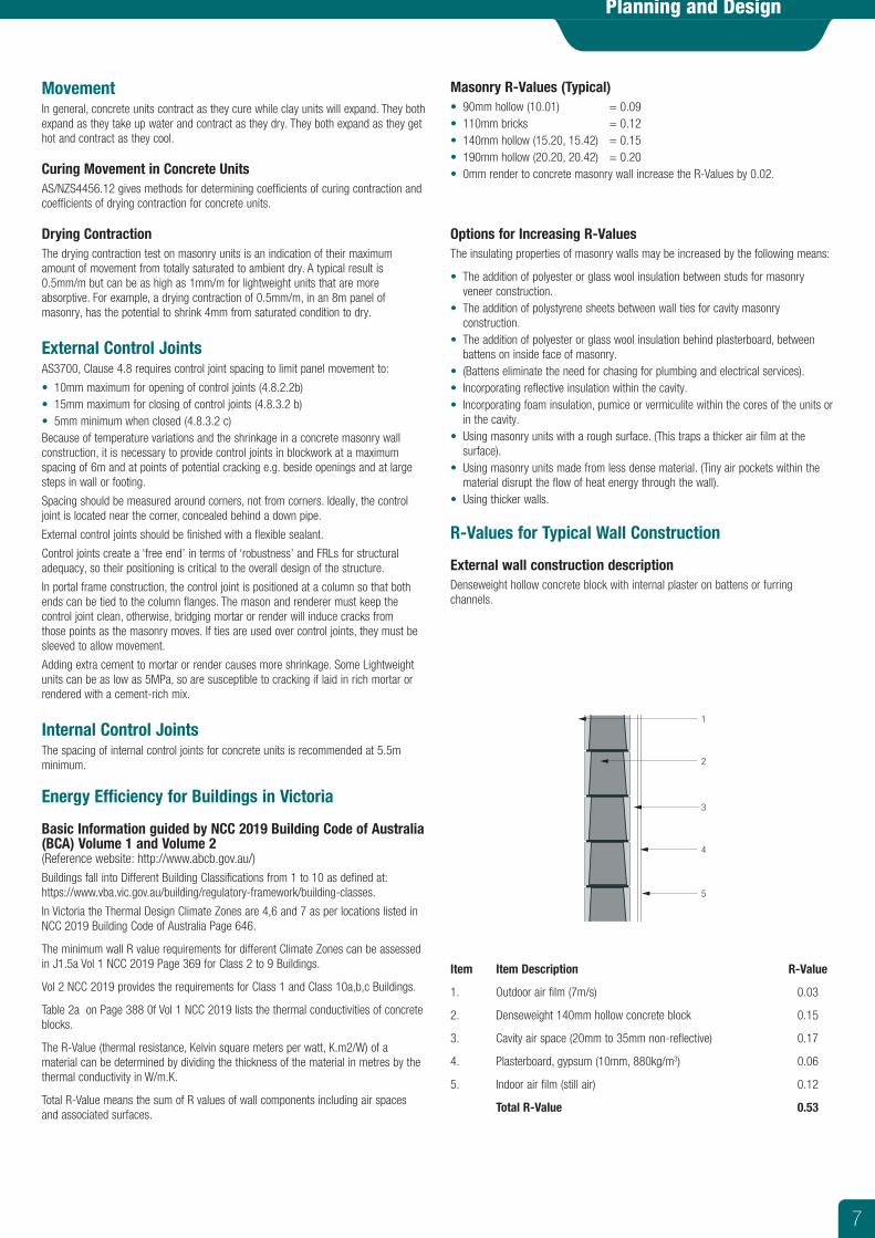
External wall construction description Denseweight hollow concrete block with internal plaster on battens or furring channels.
Item Item Description R-Value
1. Outdoor air film (7m/s) 0.03
2. Denseweight 140mm hollow concrete block 0.15
3. Cavity air space (20mm to 35mm non-reflective) 0.17
4. Plasterboard, gypsum (10mm, 880kg/m3) 0.06
5. Indoor air film (still air) 0.12
Total R-Value 0.53
1
2
3
4
5
7
Planning and Design
Construction Recommendations
GeneralRecommendations specifically applicable to reinforced masonry retaining walls include:
• The provision of clean-out openings in the bottom course to permit removal of mortar droppings and other debris and to allow vertical reinforcement to be positioned and tied. These openings should be closed (generally done with form work) before grouting.
• The use of H blocks above the first course. These blocks are easier to fill with grout which provides the required continuous protection to the reinforcement. If rebated flush-ended blocks are used in lieu of H blocks, they should be laid with alternate courses inverted to provide grout cover to horizontal reinforcement, which should be supported 20mm clear of the webs of flush-ended blocks.
• The forming of weep holes by leaving out mortar in the vertical joints at the required locations. Where H blocks are used, and weep holes are required, they may be provided by placing 25mm diameter PVC pipes through the vertical joint at the required locations. Alternatively, flush-ended blocks may be placed on either side of the required weep hole location so a mortar-free joint may be formed.
• The accurate positioning of reinforcement to give a minimum of 55mm of cover to the face of the bar and its secure tying before placing concrete or grout.
• The removal of mortar dags protruding into cores before grouting. • The use, whenever available, of ready-mixed grout to workability specifications
given in AS3700 should be used. Site-mixed grout, if used, should be mixed thoroughly in a tilting-drum mixer to the same specification as ready-mixed grout.
• The filling of all cores with grout, whether reinforced or not. This is essential to bond and protect horizontal reinforcement, to provide a full barrier against water penetration and to give maximum weight for stability.
• The thorough compaction of the grout so voids are not left. Compaction may be achieved with a high-frequency pencil vibrator, used carefully. (The main vertical reinforcing bars should not be used to compact the grout). Control joints should be built into the masonry at all points of potential cracking.
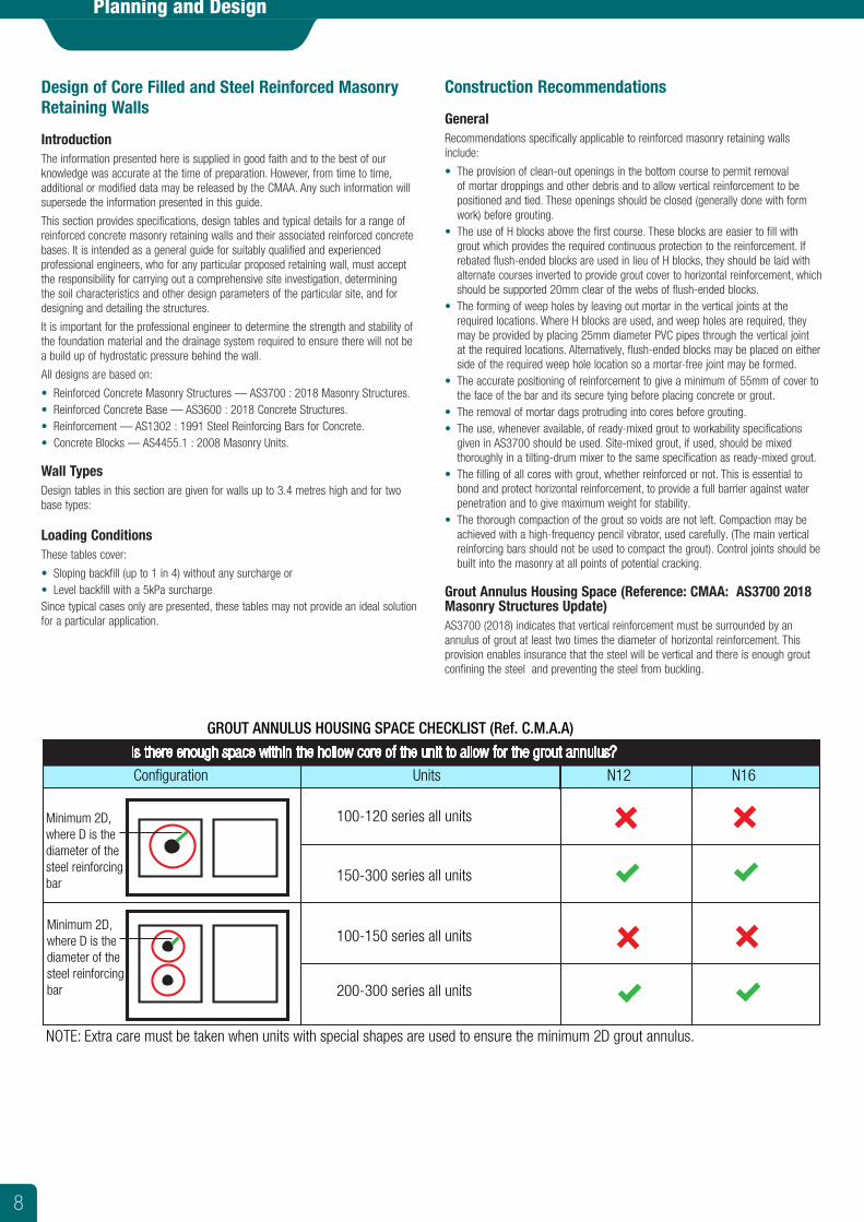
Grout Annulus Housing Space (Reference: CMAA: AS3700 2018 Masonry Structures Update)AS3700 (2018) indicates that vertical reinforcement must be surrounded by an annulus of grout at least two times the diameter of horizontal reinforcement. This provision enables insurance that the steel will be vertical and there is enough grout confining the steel and preventing the steel from buckling.
Design of Core Filled and Steel Reinforced Masonry Retaining Walls
Introduction The information presented here is supplied in good faith and to the best of our knowledge was accurate at the time of preparation. However, from time to time, additional or modified data may be released by the CMAA. Any such information will supersede the information presented in this guide.
This section provides specifications, design tables and typical details for a range of reinforced concrete masonry retaining walls and their associated reinforced concrete bases. It is intended as a general guide for suitably qualified and experienced professional engineers, who for any particular proposed retaining wall, must accept the responsibility for carrying out a comprehensive site investigation, determining the soil characteristics and other design parameters of the particular site, and for designing and detailing the structures.
It is important for the professional engineer to determine the strength and stability of the foundation material and the drainage system required to ensure there will not be a build up of hydrostatic pressure behind the wall.
All designs are based on:
• Reinforced Concrete Masonry Structures — AS3700 : 2018 Masonry Structures. • Reinforced Concrete Base — AS3600 : 2018 Concrete Structures. • Reinforcement — AS1302 : 1991 Steel Reinforcing Bars for Concrete. • Concrete Blocks — AS4455.1 : 2008 Masonry Units.
Wall Types Design tables in this section are given for walls up to 3.4 metres high and for two base types:
Loading Conditions These tables cover:
• Sloping backfill (up to 1 in 4) without any surcharge or • Level backfill with a 5kPa surcharge Since typical cases only are presented, these tables may not provide an ideal solution for a particular application.
Is there enough space within the hollow core of the unit to allow for the grout annulus?
Configuration Units N12 N16
Minimum 2D, where D is the diameter of the steel reinforcing bar
Minimum 2D, where D is the diameter of the steel reinforcing bar
GROUT ANNULUS HOUSING SPACE CHECKLIST (Ref. C.M.A.A)
NOTE: Extra care must be taken when units with special shapes are used to ensure the minimum 2D grout annulus.
100-120 series all units
150-300 series all units
100-150 series all units
200-300 series all units
8
Planning and Design
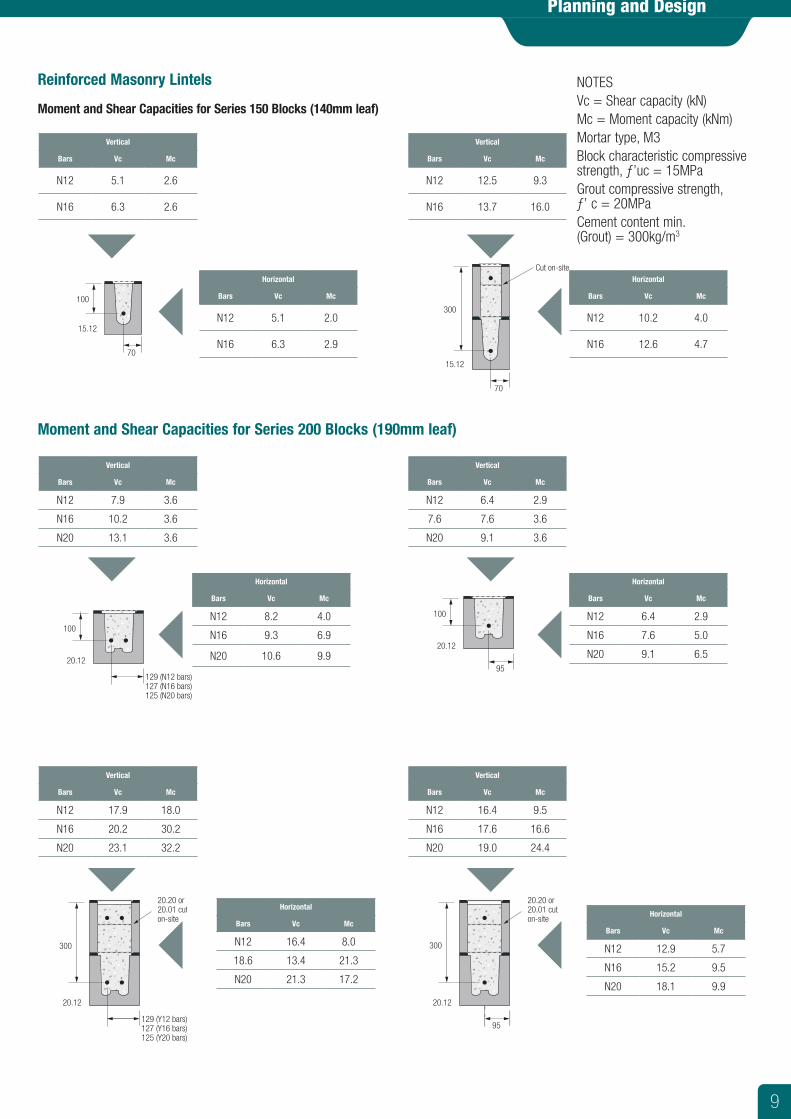
Reinforced Masonry Lintels
Moment and Shear Capacities for Series 150 Blocks (140mm leaf)
Moment and Shear Capacities for Series 200 Blocks (190mm leaf)
15.12
70
100
100
129 (N12 bars)127 (N16 bars)125 (N20 bars)
20.12
Cut on-site
15.12
70
300
Vertical
Bars Vc Mc
N12 5.1 2.6
N16 6.3 2.6
Vertical
Bars Vc Mc
N12 7.9 3.6
N16 10.2 3.6
N20 13.1 3.6
Vertical
Bars Vc Mc
N12 17.9 18.0
N16 20.2 30.2
N20 23.1 32.2
Vertical
Bars Vc Mc
N12 12.5 9.3
N16 13.7 16.0
Vertical
Bars Vc Mc
N12 6.4 2.9
7.6 7.6 3.6
N20 9.1 3.6
Vertical
Bars Vc Mc
N12 16.4 9.5
N16 17.6 16.6
N20 19.0 24.4
NOTESVc = Shear capacity (kN)Mc = Moment capacity (kNm)Mortar type, M3Block characteristic compressive strength, ƒ’uc = 15MPaGrout compressive strength, ƒ’ c = 20MPaCement content min. (Grout) = 300kg/m3
100
95
20.12
129 (Y12 bars)127 (Y16 bars)125 (Y20 bars)
20.20 or20.01 cuton-site
300
20.12
95
300
20.12
20.20 or20.01 cuton-site
Horizontal
Bars Vc Mc
N12 5.1 2.0
N16 6.3 2.9
Horizontal
Bars Vc Mc
N12 10.2 4.0
N16 12.6 4.7
Horizontal
Bars Vc Mc
N12 8.2 4.0
N16 9.3 6.9
N20 10.6 9.9
Horizontal
Bars Vc Mc
N12 6.4 2.9
N16 7.6 5.0
N20 9.1 6.5
Horizontal
Bars Vc Mc
N12 16.4 8.0
18.6 13.4 21.3
N20 21.3 17.2
Horizontal
Bars Vc Mc
N12 12.9 5.7
N16 15.2 9.5
N20 18.1 9.9
9
Backfill Drainage
Planning and Design
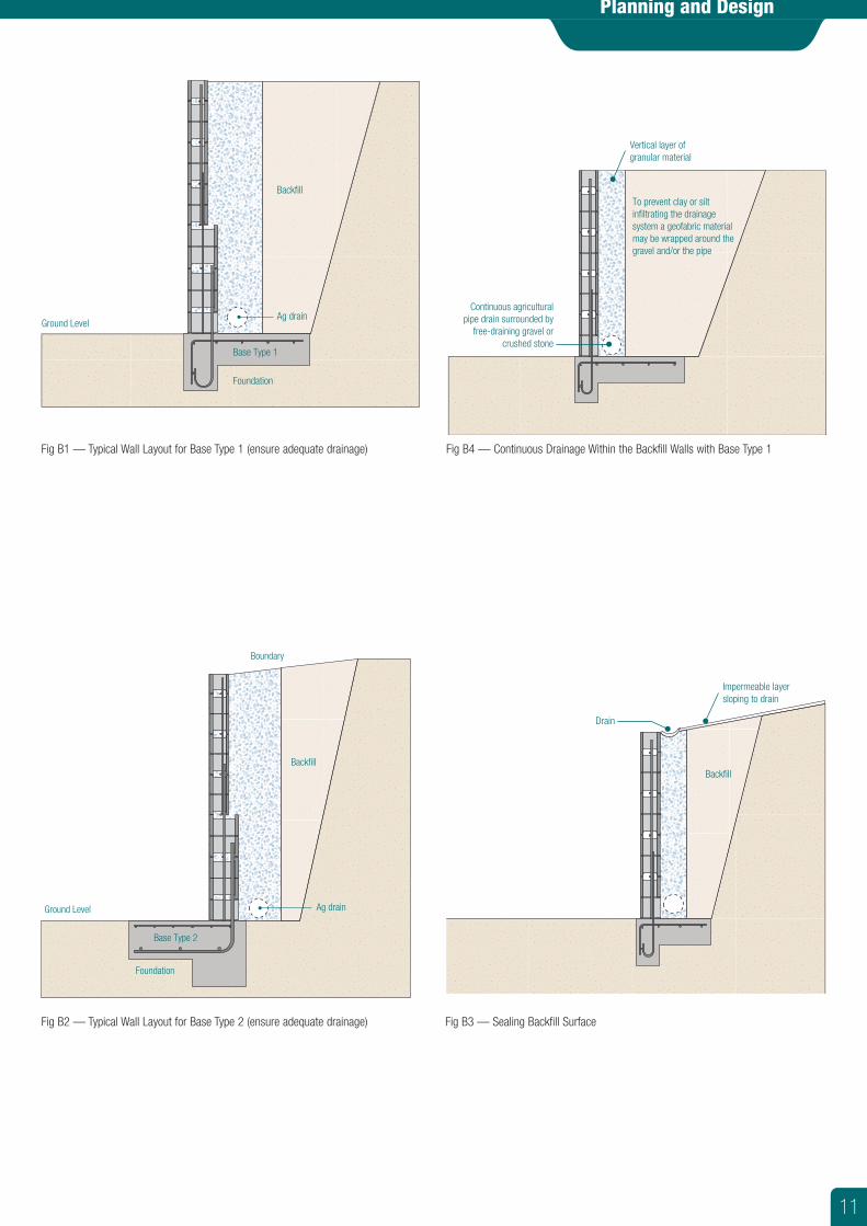
It is essential that steps be taken to prevent the backfill behind the wall from becoming saturated. These steps should include:
Sealing Backfill Surface To prevent saturation of backfill by surface run-off, the surface of the backfill should be sealed by covering it with a compacted layer of low permeability material. The surface should be sloped towards an open drain.
Continuous Drainage Within the Backfill This can be achieved by placing free-draining gravel or crushed stone to a width of approximately 300mm immediately behind the wall with a continuous agricultural pipe located at the base of the wall. The outlets of the pipe must be beyond the ends of the wall unless the pipe is connected to a proper storm water drainage system.
For higher walls, or in cases where excessive groundwater exists, it may be necessary to provide another agricultural pipe drain at mid-height of the wall.
Care must be taken to ensure that clay and silt do not infiltrate the drainage material or agricultural pipe. The use of a geofabric envelope around the gravel and/or a geofabric sock over the pipe will assist.
Weep holes Weep holes should be provided above the finished ground level. A drain should be provided in front of the wall to prevent saturation of the ground.
The horizontal spacing of the weep holes depends on the provisions made for directing water towards the holes. The simplest, but most effective, method is to place one or two buckets of free-draining gravel or crushed stone around the intake end of each hole. In this case, the horizontal spacing should not exceed 1.5 metres. If the layers of draining material are continuous for the full length of the wall, weep hole spacing may be increased to an extent depending on the quantity of water expected.
Note: For walls higher than 2200mm, a second row of weep holes may be required. However, staining of the wall could result.
Water Penetration If it is considered necessary to reduce the passage of moisture through the wall, for aesthetic or other reasons such as aggressive groundwater, the earth face of the wall should be treated with an appropriate sealer such as water-resistant render or water-resistant paint, or by tanking with bituminous materials.
Structural Design Guidelines
Acceptable Soil Combinations • For retaining walls founded on sand (Type A soil), the retained material must be
similar and with a friction angle of 38° or greater, e.g. Type A soil — clean sand or gravel.
• For retaining walls founded on other soils, the retained material must be a free draining material with a friction angle of 27° or greater, e.g. Type B soil — coarse grained with silt or some clay.
10
Planning and Design
Ground Level
Backfill
Ag drain
Foundation
Base Type 1
Fig B1 — Typical Wall Layout for Base Type 1 (ensure adequate drainage) Fig B4 — Continuous Drainage Within the Backfill Walls with Base Type 1
Vertical layer ofgranular material
To prevent clay or silt infiltrating the drainage system a geofabric materialmay be wrapped around the gravel and/or the pipe
Continuous agricultural pipe drain surrounded by
free-draining gravel or crushed stone
Fig B2 — Typical Wall Layout for Base Type 2 (ensure adequate drainage) Fig B3 — Sealing Backfill Surface
Ground Level
Boundary
Backfill
Foundation
Base Type 2
Ag drain
Drain
Backfill
Impermeable layer sloping to drain
11
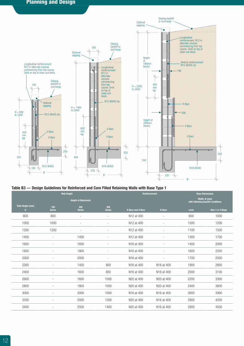
190
400
230
B
B
250
550
330
300
600minlap
H = 1400 to 2000
H = 2200 to 3400
Heightof190mmblocks
Height of 290mmblocks
450minlap
Longitudinalreinforcement:N12 in alternatecoursescommencingfrom top course. Omit on top of clean-outblock
Longitudinalreinforcement: N12 in alternate courses commencing from top course. Omit on top of clean-out block
Slopingbackfill or surcharge
Sloping backfill or surchargeOptional
capping
Vertical reinforcement: N12 @400 cts
N12 @400 cts
N16 @400N16 @400
V Bars
X Bars
V Bars
X Bars
K Bars
Optionalcapping
290
190
140
350
180
B
200
450minlap
H = 800 to 1200
Longitudinal reinforcement: N12 in alternate courses commencing from top course. Omit on top of clean-out block
Slopingbackfill or surcharge
N12 @400 cts
N12 @400
V Bars
X Bars
Optionalcapping
Table B3 — Design Guidelines for Reinforced and Core Filled Retaining Walls with Base Type 1 Wall Height Reinforcement Base Dimensions
Total Height (mm)
H
Height of Blockwork
X-Bars and V-Bars K-Bars
Width, B (mm) with following backfill conditions
150 Series
200 Series
300 Series Level Max 1 in 4 Slope
800 800 - - N12 at 400 - 800 1000
1000 1000 - - N12 at 400 - 1000 1200
1200 1200 - - N12 at 400 - 1100 1500
1400 - 1400 - N12 at 400 - 1300 1700
1600 - 1600 - N16 at 400 - 1400 2000
1800 - 1800 - N16 at 400 - 1600 2200
2000 - 2000 - N16 at 400 - 1700 2500
2200 - 1400 800 N16 at 400 N16 at 400 1900 2800
2400 - 1600 800 N16 at 400 N16 at 400 2000 3100
2600 - 1600 1000 N20 at 400 N20 at 400 2200 3300
2800 - 1800 1000 N20 at 400 N20 at 400 2400 3600
3000 - 2000 1000 N16 at 400 N16 at 400 2600 3900
3200 - 2000 1200 N20 at 400 N16 at 400 2800 4200
3400 - 2000 1400 N20 at 400 N16 at 400 2900 4500
Planning and Design
12
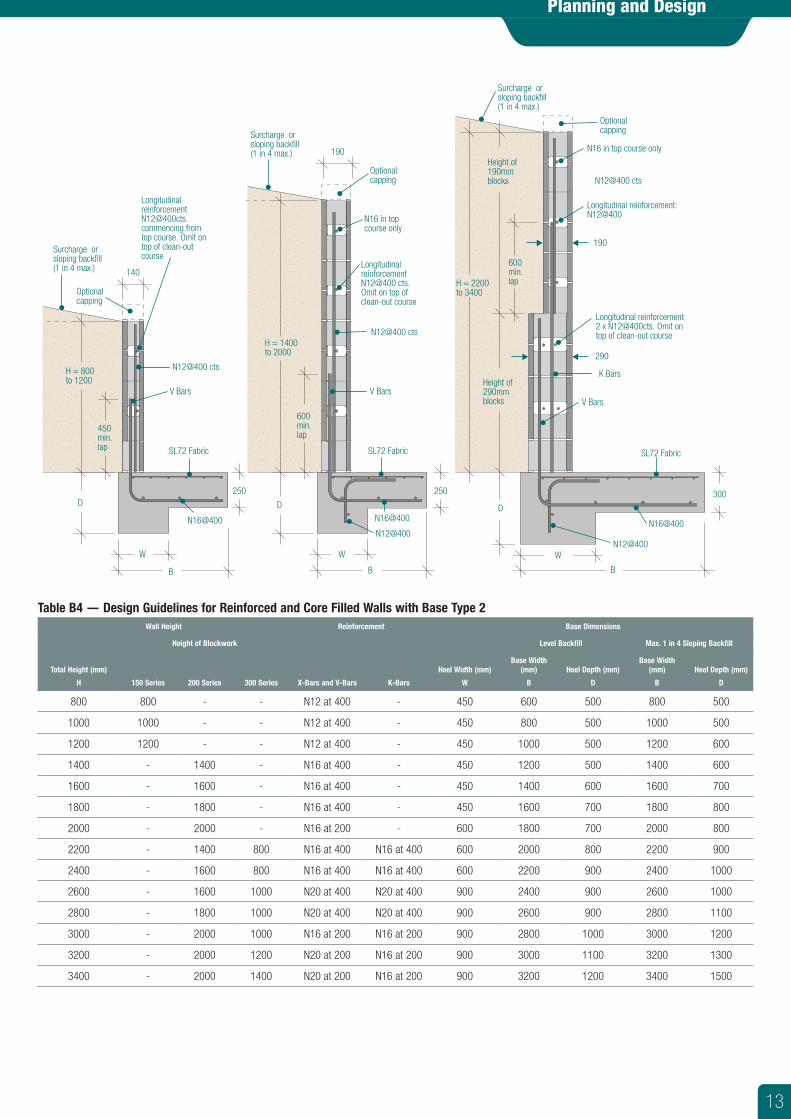
Table B4 — Design Guidelines for Reinforced and Core Filled Walls with Base Type 2 Wall Height Reinforcement Base Dimensions
Total Height (mm)
H
Height of Blockwork
X-Bars and V-Bars K-Bars
Heel Width (mm)
W
Level Backfill Max. 1 in 4 Sloping Backfill
150 Series 200 Series 300 Series
Base Width (mm)
B
Heel Depth (mm)
D
Base Width (mm)
B
Heel Depth (mm)
D
800 800 - - N12 at 400 - 450 600 500 800 500
1000 1000 - - N12 at 400 - 450 800 500 1000 500
1200 1200 - - N12 at 400 - 450 1000 500 1200 600
1400 - 1400 - N16 at 400 - 450 1200 500 1400 600
1600 - 1600 - N16 at 400 - 450 1400 600 1600 700
1800 - 1800 - N16 at 400 - 450 1600 700 1800 800
2000 - 2000 - N16 at 200 - 600 1800 700 2000 800
2200 - 1400 800 N16 at 400 N16 at 400 600 2000 800 2200 900
2400 - 1600 800 N16 at 400 N16 at 400 600 2200 900 2400 1000
2600 - 1600 1000 N20 at 400 N20 at 400 900 2400 900 2600 1000
2800 - 1800 1000 N20 at 400 N20 at 400 900 2600 900 2800 1100
3000 - 2000 1000 N16 at 200 N16 at 200 900 2800 1000 3000 1200
3200 - 2000 1200 N20 at 200 N16 at 200 900 3000 1100 3200 1300
3400 - 2000 1400 N20 at 200 N16 at 200 900 3200 1200 3400 1500
190
D
W
B B
250250
290
D
W
300
190
600min.lap
H = 1400 to 2000
H = 2200 to 3400
Height of 190mmblocks
Height of 290mmblocks
600min.lap
Longitudinal reinforcement: N12@400
N16 in top course only
N16 in top course only
Optionalcapping
N12@400 cts
N12@400 cts
V Bars
SL72 Fabric
N16@400N16@400 N16@400
V Bars
K Bars
Optionalcapping
SL72 Fabric
140
D
W
B
450min.lap
H = 800 to 1200
[email protected] from top course. Omit on top of clean-out course
Surcharge or sloping backfill (1 in 4 max.)
Surcharge or sloping backfill (1 in 4 max.)
Surcharge or sloping backfill (1 in 4 max.)
N12@400 cts
V Bars
SL72 Fabric
Optionalcapping
Longitudinal reinforcement 2 x N12@400cts. Omit on top of clean-out course
LongitudinalreinforcementN12@400 cts. Omit on top of clean-out course
N12@400N12@400
Planning and Design
13
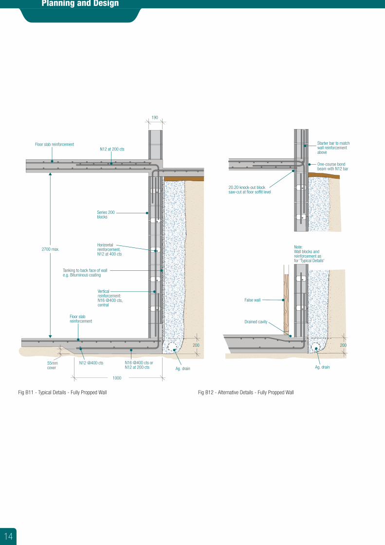
200
55mmcover
1000
N16 @400 cts or N12 at 200 cts
N12 @400 cts
2700 max.
Floor slab reinforcement
Floor slab reinforcementN12 at 200 cts
Ag. drain
Vertical reinforcement:N16 @400 cts, central
Tanking to back face of wall e.g. Bituminous coating
Series 200 blocks
Horizontalreinforcement,N12 at 400 cts
Starter bar to match wall reinforcement above
One-course bond beam with N12 bar
Note:Wall blocks and reinforcement as for 'Typical Details'
200
Drained cavity
False wall
Ag. drain
190
20.20 knock-out block saw-cut at floor soffit level
Planning and Design
Fig B11 - Typical Details - Fully Propped Wall Fig B12 - Alternative Details - Fully Propped Wall
14
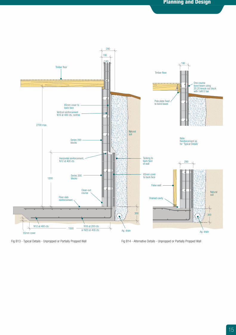
300 300
55mm cover
1500N16 at 200 ctsN12 at 400 cts
2700 max.
1200
Timber floor
Ag. drain
Vertical reinforcement N16 at 400 cts, central
65mm cover to back face
65mm cover to back face
Tanking to back face of wall
Series 200 blocks
Horizontal reinforcement, N12 at 400 cts
Note:Reinforcement as for ‘Typical Details’
Drained cavity
False wall
Ag. drain
Series 300 blocks
190
190
290
290
140
Timber floor
Pole plate fixed to bond beam
One-coursebond beam using 20.20 knock-out block with 1xN12 bar
or N20 at 400 cts
Floor slab reinforcement
Naturalsoil
Naturalsoil
Clean-outcourse
Planning and Design
Fig B13 - Typical Details - Unpropped or Partially Propped Wall Fig B14 - Alternative Details - Unpropped or Partially Propped Wall
15
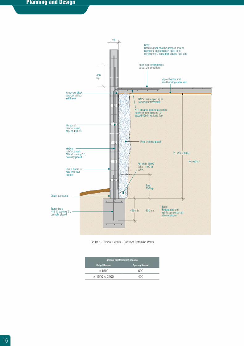
450 min.
Bars450 lap
'H' (2200 max.)
600 min.
Ag. drain 65mØ fall at 1:100 to outlet
Free-draining gravel
Note:Footing size and reinforcement to suit site conditions
Note:Retaining wall shall be propped prior to backfilling and remain in place for a minimum of 7 days after placing floor slab
Vertical reinforcement:N12 at spacing 'S', centrally placed
Horizontal reinforcement,N12 at 400 cts
Knock-out block saw-cut at floor soffit level
Starter bars,N12 @ spacing 'S',centrally placed
Use H blocks for sub-floor wall section
Clean-out course
190
Floor slab reinforcementto suit site conditions
Vapour barrier and sand bedding under slab
Natural soil
450lap
N12 at same spacing as vertical reinforcement (spacing 'S') lapped 450 in wall and floor
N12 at same spacing as vertical reinforcement
Vertical Reinforcement Spacing
Height H (mm) Spacing S (mm)
≤ 1500 600
> 1500 ≤ 2200 400
Planning and Design
Fig B15 - Typical Details - Subfloor Retaining Walls
16
Fire Design
Masonry Design for Fire Resistance
Fire Resistance Levels (FRL) FRL come from the Building Code of Australia’s (BCA) tables for Type A, B or C construction. The Type of construction depends on the Class of building and the number of stories or floors.
There are 3 figures in the Fire Resistance Level. e.g.: FRL 60/120/120 meaning Structural Adequacy for 60 minutes / Integrity for 120 minutes / Insulation for 120 minutes.
Structural Adequacy This governs the wall height, length, thickness and restraints. Masonry unit suppliers do not control the wall height, length or restraints, therefore do not control Structural Adequacy. However, information that is useful in the design of masonry walls is the maximum Slenderness ratio (Srf). National Masonry® provides Srf information for all of its masonry units, and its use is discussed in more detail later.
Integrity This is the resistance to the passage of flame or gas. To provide ‘integrity’, masonry walls must be structurally adequate because cracks that form when it bows can allow flame through the wall. Since the masonry unit supplier does not control Structural Adequacy, they cannot control ‘integrity’ either.
Insulation This is resistance to the passage of heat. Insulation is governed by the type and thickness of the material used to produce the masonry unit. This is controlled by the masonry unit manufacturer. In relation to FRL, masonry must always provide ‘Insulation’ to an equal or better level than is required for ‘Integrity’.
Robustness Wall design must take into account whether Robustness governs (Refer to FRL Graphs and Page 5 of this guide)
Masonry Design for Structural Adequacy FRL
Legend for the following formulae Srf - the slenderness ratio in design for fire resistance for structural adequacy. See
table C2 for maximum Srf.
avf - 0.75 if the member is laterally supported along its top edge.
- 2.0 if the member is not laterally supported along its top edge.
H - the clear height of a member between horizontal lateral supports; or
- for a member without top horizontal support, the overall height from the bottom lateral support.
t - the overall thickness of the member cross-section perpendicular to the principal axis under consideration; for members of cavity wall construction, the wall thickness assessed is in accordance with Clause 6.3.2.1(a) and (b).
ah - 1.0 if the member is laterally supported along both its vertical edges.
- 2.5 if the member is laterally supported along one vertical edge.
L - The clear length of a wall between vertical lateral supports; or
- for a wall without vertical support at one end or at a control joint or for walls containing openings, the length to that unsupported end or control joint or edge of opening.
NOTE: A control joint in a wall, or an edge to an opening in a wall, shall be regarded as an unsupported edge to the wall unless specific measures are taken to provide adequate lateral support at the edge.
Structural Adequacy may be overridden by design for robustness; wind; live or earthquake loads.
A fire on one side of a wall will heat that side, making it expand and lean towards the fire. When the lean or bow reaches half the thickness of the original wall, the wall becomes structurally inadequate. The formulae in AS3700, Clause 6.3.2.2 limits masonry panel size, depending on its restraints and thickness.
The Slenderness ratio (Srf) of the proposed wall is calculated as per Clause 6.3.2.2. If this value is less than the maximum Srf in Table 6.1 [or the Srf calculated from Fire Tests and Clause 6.3.3(b)(ii)], then the wall complies. If the Srf of the wall is greater than the maximum permissible, it is recalculated for an increased thickness and/or extra restraints.
There are 4 formulae for calculating Srf: 6.3.2.2 (1) and (2) are the HEIGHT formulae.
Formula 1 & 2 is: Srf =avf H
t
6.3.2.2 (3) is the PANEL ACTION formula.
Formula 3 is: Srf =0.7 √t avf H ah L
6.3.2.2 (4) is the LENGTH formula.
Formula 4 is: Srf =ah L
t
The actual Srf is the lesser of the resulting figures.
Formula (1) and (2) always govern where there is no end restraint, and often govern where walls are long, relative to their height. Projects with multiple wall lengths (e.g.: home units) can use this formula as a ‘one size fits all’ method of calculating the masonry thickness.
Formula (3) allows a wall to exceed the height given by formula (1) and (2) provided at least one end is restrained as well as the top.
Formula (4) governs the wall length, often where there is no top restraint (e.g.: portal frame factories) and where walls are short, relative to their height (e.g.: a lift well or vent shaft).
From a suppliers perspective, it is helpful to be able to calculate the maximum height* for a given thickness (masonry unit),
e.g. H =Srf tAvf
and calculate the thickness from a given wall size.
t =Avf HSrf
where ‘t’ is the OVERALL thickness, whether the units are solid or hollow.
NOTE:* Refer to the Structural Adequacy Selection Graphs on pages 21 to 27 for maximum height values.
For cavity walls, two thirds of the total thickness can be used for t, provided that BOTH leaves are restrained in the same positions (e.g.: external leaf stops at slab also). If the external leaf is a veneer to the slab edge, the internal leaf must provide the Structural Adequacy FRL on its own.
For reinforced masonry, the Srf of 36, from Table 6.1 AS3700 may be used. Reinforcement can be horizontal, as bond beams when spanning between columns. Reinforcement can be vertical, as filled cores when spanning between slabs. In either case, reinforcement can be spaced up to 2m apart, depending on span. This reinforcement stiffens the masonry and resists bowing. Reinforced walls with Srf < 36 have a 240 minute FRL for Structural Adequacy.
All calculations should be checked by an engineer. Other loads may supersede Structural Adequacy requirements.
Masonry Design for Integrity FRL
(The resistance to the passage of flame or gas). It is impractical to provide test results for all possible masonry wall designs, and therefore ‘Integrity’ must be proved in some other way. With masonry wall design, the most practical way to prove ‘Integrity’ is to prove ‘Structural Adequacy’ and ‘Insulation’ equal to or better than the ‘Integrity’ requirement. (Logically, if the wall is designed to minimise ‘bowing’ it will not crack and therefore resist the passage of flame and gas for the specified time).
This method is also the best way to prove ‘integrity’ even when a wall may not be required to comply with a ‘structural adequacy’ FRL value, such as is the case with non loadbearing walls. e.g.: if the BCA requires an FRL of -/90/90, the wall has no actual ‘structural adequacy’ requirement, but to prove integrity of 90 minutes, the wall must be structurally adequate for 90 minutes.
Masonry Design for Insulation FRL Insulation is the one FRL component that a masonry unit manufacturer does control. It is governed by the ‘type of material’ and the ‘material thickness’.
17
‘Material thickness’ is defined in AS3700, Clause 6.5.2 as the overall thickness for solid and grouted units and units with cores not more than 30% of the unit’s overall volume.
For hollow units (cores > 30%), the material thickness is the net volume divided by the face area.
For cavity walls, t = the sum of material thicknesses in both leaves. (not two thirds as for the Structural Adequacy FRL).
Options for Increasing FRLs The Structural Adequacy FRL can be increased by adding wall stiffeners, by increasing the overall thickness, by adding reinforcement or by protecting the wall with USG Boral Plasterboard ‘FireStop’ board, fixed to furring channels (on both sides of the wall if a fire rating is required from both sides).
Integrity FRLs are increased by increasing the other two FRL values to the required Integrity FRL.
Insulation FRLs can be increased by core filling, by adding another leaf of masonry, by rendering both sides of the wall if the fire can come from either side. NOTE: Only ONE thickness of render is added to the material thickness and that must be on the ‘cold’ side because the render on the exposed face will drop off early in a fire). USG Boral ‘FireStop’ plasterboard on furring channels can increase the Insulation FRL from either side. Unlike render, the USG Boral FireStop and furring system does not drop off the hot side so quickly due to the board’s fire resistance, the mechanical fixing of the board to furring and the furring to the wall.
Effect of Chases on Fire Rated Masonry
Structural Adequacy FRL To assess the effect of chases on Structural Adequacy FRLs, the direction in which the wall spans must be taken into account.
Walls spanning vertically may be chased vertically. The horizontal chase is limited to 4 times the wall thickness.
Walls spanning vertically and horizontally may be chased horizontally up to half the wall length. Horizontal chases should be kept to a bare minimum. Walls spanning vertically and horizontally may be chased vertically up to half the wall height.
If these limits are exceeded, the masonry design thickness must be reduced by the depth of the recess or, in the case of vertical chases, designed as 2 walls with unsupported ends at the chase.
Integrity and Insulation FRLs Maximum depth of recess is 30mm. Maximum area is 1,000mm2. Total maximum area on both sides of any 5m2 of wall is 100,000mm2
If these limits are exceeded, the masonry design thickness must be reduced by the depth of the recess.
Recesses for Services Recesses that are less than half of the masonry thickness and are less than 10,000mm2 for both sides within any 5m2 of the masonry, do not have an effect on fire ratings.
If these limits are exceeded, the masonry design thickness must be reduced by the depth of the recess.
How to Select National Masonry® Units for Fire Rated Walls All design information, table data and graphs in this guide are derived from formulae in AS3700 : 2018 Masonry Structures, Part 6.3 for Structural Adequacy Fire Resistance Levels (FRL) and Part 4.6 for Robustness.
Tables and graphs assume all walls are built on concrete slabs or broad footings and have adequate restraints. Piers, cavity walls, freestanding walls, earthquake, wind and other loads are not addressed in this guide. All fire rated walls should be designed by a suitably qualified engineer.
Fire Design
Step 1 Determine required wall FRL from the Building Code of Australia (BCA).
The Building Code of Australia (BCA), Section C defines the CLASS and TYPE of building and designates the required Fire Resistant Level (FRL) in terms of three criteria.
e.g. 120/60/60
Structural Adequacy = 120/ Integrity=60 / Insulation = 60
NOTE: For masonry wall design, the FRL for any given wall must comply with:
Structural Adequacy ≥ Integrity ≤ Insulation
e.g. If the BCA required FRL is: -/120/60
Then the chosen wall design must have an actual FRL of: 120/120/120 or better.
Refer to the section ‘Masonry Design for Integrity FRL’ for additional explanation.
Worked Example
A 6m high, 6m long fire rated, non-loadbearing wall in 3 storey warehouse. BCA specifies Class 7, Type b Construction.
BCA Volume 1, Table 4 specifies an FRL 240/240/240
Step 2 Select an appropriate National Masonry® Unit based on the FRL ‘Insulation Requirement’.
The third figure in an FRL rating is the ‘Insulation’.
Table C1 provides the ‘Insulation’ values for the various National Masonry® units.
Check the ‘Materials Attributes’ (see notes below the table) to ensure the selection is fit for its purpose.
Worked Example From Table C1, the following units all achieve 240 minutes FRL for ‘Insulation’:—
• 12.401, 15.401, 15.483 and 20.401 • Grout Filled Masonry (190mm) 20.42 and 20.48 (however the use of Scoria Blend
may be more cost effective if the wall is non-loadbearing).
Material Attributes (Victoria) Concrete-Basalt Brick ƒ’uc=10MPa (BRICKAG) MPa Concrete-Basalt is a dense weight, load-bearing material. The 45% basalt content of these bricks allows the use of the higher Slenderness ratios AS3700, Table 6.1. Its Insulation FRLs are slightly higher than clay units. The material is slightly more dense than clay so acoustic performance is slightly higher for rendered walls (mass law). Acoustic performance with plasterboard is better than clay because resonances are dampened by its higher porosity.Designer Range ƒ’uc=10MPa, f’uc=15MPa(140mm,190mm) Blocks provide a 60 or 90 minute Insulation FRL. Suitable for LOADBEARING applications. Standard Grey Block(AG, UNV) ƒ’uc=15MPa Made as hollow, reduced core and solid units for 60, 90 and 120-minute Insulation FRLs. Used for loadbearing and non-loadbearing masonry, 140 and 190mm thick units can be partially reinforced for walls of portal frame buildings and houses in cyclonic areas. Standard Grey block fire rating is significantly improved by core filling.Core Fill Block(H Block AG) ƒ’uc=15MPa Made with recessed webs to accommodate horizontal steel. Used for cantilever-design retaining walls, basement walls and for large, loadbearing walls requiring 120 or 240-minute Insulation FRLs. Scoria Blend Non-Load High Fire Rated Block(FR) ƒ ’uc = 8 MPa Offers excellent Insulation and Structural Adequacy FRLs for NONLOADBEARING fire rated walls. 10% lighter than Standard Ash Grey units. Scoria Blend is hard, durable and suitable for paint or render. Acoustic performance with plasterboard linings is excellent. Acoustic performance with render is medium range. Scoria Blend Load High Fire Rated Block(LWS) ƒ ’uc = 15 MPa Offers excellent Insulation and Structural Adequacy FRLs for LOADBEARING fire rated walls. 10% lighter than Standard Ash Grey units. Scoria Blend is hard, durable and suitable for paint or render. Acoustic performance with plasterboard linings is excellent. Acoustic performance with render is medium range.LWS block walls can go higher than AG/UNV walls due to AS3700 fire test results.The incorporation of Victorian LWS (Light Weight Structural) units has seen an increase in the use of stiffeners and partial core fill that this high strength 15MPa fire rated unit offers i.e. Less core fill, more competitive walling.Scoria Quick Brick SB(FR) ƒ ’uc = 4 MPa Insulation FRL of 240 minutes. High slenderness ratio (Srf) for Structural Adequacy FRL. Suitable for NON LOADBEARING fire rated walls. Light weight, 20% lighter than Standard Ash Grey units. Acoustic performance with plasterboard linings is excellent.
18
Fire Design
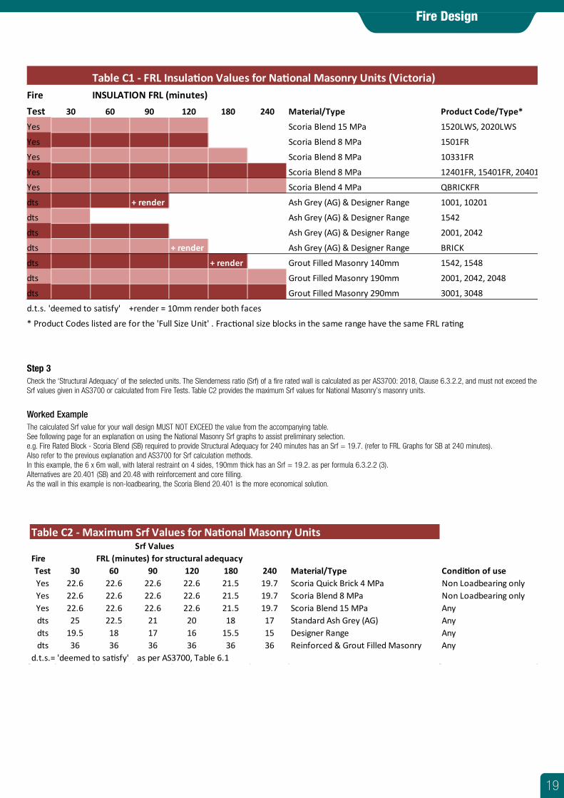
Step 3Check the ‘Structural Adequacy’ of the selected units. The Slenderness ratio (Srf) of a fire rated wall is calculated as per AS3700: 2018, Clause 6.3.2.2, and must not exceed the Srf values given in AS3700 or calculated from Fire Tests. Table C2 provides the maximum Srf values for National Masonry’s masonry units.
Worked ExampleThe calculated Srf value for your wall design MUST NOT EXCEED the value from the accompanying table.See following page for an explanation on using the National Masonry Srf graphs to assist preliminary selection.e.g. Fire Rated Block - Scoria Blend (SB) required to provide Structural Adequacy for 240 minutes has an Srf = 19.7. (refer to FRL Graphs for SB at 240 minutes).Also refer to the previous explanation and AS3700 for Srf calculation methods.In this example, the 6 x 6m wall, with lateral restraint on 4 sides, 190mm thick has an Srf = 19.2. as per formula 6.3.2.2 (3).Alternatives are 20.401 (SB) and 20.48 with reinforcement and core filling.As the wall in this example is non-loadbearing, the Scoria Blend 20.401 is the more economical solution.
Srf ValuesFire FRL (minutes) for structural adequacyTest 30 60 90 120 180 240 Material/Type Condi�on of useYes 22.6 22.6 22.6 22.6 21.5 19.7 Scoria Quick Brick 4 MPa Non Loadbearing onlyYes 22.6 22.6 22.6 22.6 21.5 19.7 Scoria Blend 8 MPa Non Loadbearing onlyYes 22.6 22.6 22.6 22.6 21.5 19.7 Scoria Blend 15 MPa Anydts 25 22.5 21 20 18 17 Standard Ash Grey (AG) Anydts 19.5 18 17 16 15.5 15 Designer Range Anydts 36 36 36 36 36 36 Reinforced & Grout Filled Masonry Any
d.t.s.= 'deemed to sa�sfy' as per AS3700, Table 6.1
Table C2 - Maximum Srf Values for Na�onal Masonry Units
Table C1 - FRL Insula�on Values for Na�onal Masonry Units (Victoria)Fire INSULATION FRL (minutes)Test 30 60 90 120 180 240 Material/Type Product Code/Type*
Yes Scoria Blend 15 MPa 1520LWS, 2020LWS
Yes Scoria Blend 8 MPa 1501FR
Yes Scoria Blend 8 MPa 10331FR
Yes Scoria Blend 8 MPa 12401FR, 15401FR, 20401FR
Yes Scoria Blend 4 MPa QBRICKFR
dts + render Ash Grey (AG) & Designer Range 1001, 10201
dts Ash Grey (AG) & Designer Range 1542
dts Ash Grey (AG) & Designer Range 2001, 2042
dts + render Ash Grey (AG) & Designer Range BRICK
dts + render Grout Filled Masonry 140mm 1542, 1548
dts Grout Filled Masonry 190mm 2001, 2042, 2048
dts Grout Filled Masonry 290mm 3001, 3048
d.t.s. 'deemed to sa�sfy' +render = 10mm render both faces
* Product Codes listed are for the 'Full Size Unit' . Frac�onal size blocks in the same range have the same FRL ra�ng
19
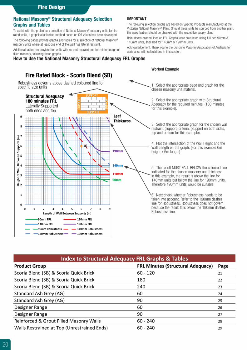
IMPORTANT The following selection graphs are based on Specific Products manufactured at the Victorian National Masonry® Plant. Should these units be sourced from another plant, the specification should be checked with the respective supply plant.
Robustness dashed lines on FRL Graphs were calculated using full bed 90mm & 110mm units, shell bed for 140mm & 190mm units.
Acknowledgement: Thank you to the Concrete Masonry Association of Australia for assistance with calculations in this section.
Fire Design
National Masonry® Structural Adequacy Selection Graphs and Tables To assist with the preliminary selection of National Masonry® masonry units for fire rated walls, a graphical selection method based on Srf values has been developed.
The following pages provide graphs and tables for a selection of National Masonry® masonry units where at least one end of the wall has lateral restraint.
Additional tables are provided for walls with no end restraint and for reinforced/grout filled masonry, following these graphs.
How to Use the National Masonry Structural Adequacy FRL Graphs
Worked Example
1. Select the appropriate page and graph for the chosen masonry unit material.
2. Select the appropriate graph with Structural Adequacy for the required minutes. (180 minutes for this example).
3. Select the appropriate graph for the chosen wall restraint (support) criteria. (Support on both sides, top and bottom for this example).
4. Plot the intersection of the Wall Height and the Wall Length on the graph. (For this example 6m height x 6m length).
5. The result MUST FALL BELOW the coloured line indicated for the chosen masonry unit thickness. In this example, the result is above the line for 140mm units but below the line for 190mm units. Therefore 190mm units would be suitable.
6. Next check whether Robustness needs to be taken into account. Refer to the 190mm dashes line for Robustness. Robustness does not govern because the result falls below the 190mm dashes Robustness line.
0
1
2
3
4
5
6
7
8
9
0 1 2 3 4 5 6 7 8 9
Heig
ht o
f Wal
l Bet
wee
n Su
ppor
ts (m
)
Length of Wall Between Supports (m)0
1
2
3
4
5
6
7
8
9
0 1 2 3 4 5 6 7 8 9
Hei
ght o
f Wal
l Bet
wee
n Su
ppor
ts (m
)
Length of Wall Between Supports (m)
90mm FRL 110mm FRL140mm FRL 190mm FRL90mm Robustness 110mm Robustness140mm Robustness 190mm Robustness
LeafThickness
190mm
140mm
110mm
90mm
SUPPORT
SUPPORT
SUPP
ORT
SUPP
ORTStructural Adequacy
180 minutes FRLLaterally Supportedboth ends and top
Fire Rated Block - Scoria Blend (SB)Robustness governs above dashed coloured line forspecific size units
Product Group FRL Minutes (Structural Adequacy) PageScoria Blend (SB) & Scoria Quick Brick 60 - 120 21
Scoria Blend (SB) & Scoria Quick Brick 180 22
Scoria Blend (SB) & Scoria Quick Brick 240 23
Standard Ash Grey (AG) 60 24
Standard Ash Grey (AG) 90 25
Designer Range 60 26
Designer Range 90 27
Reinforced & Grout Filled Masonry Walls 60 - 240 28
Walls Restrained at Top (Unrestrained Ends) 60 - 240 29
Index to Structural Adequacy FRL Graphs & Tables
20
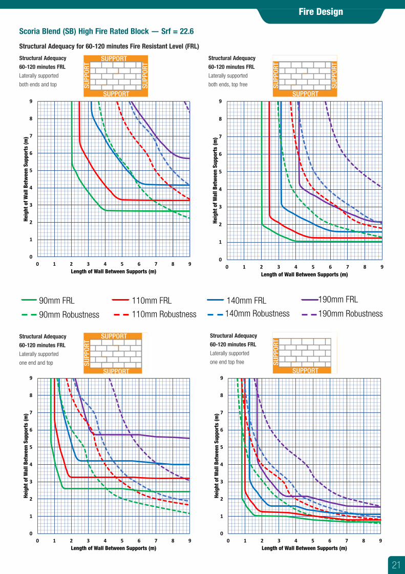
Scoria Blend (SB) High Fire Rated Block — Srf = 22.6
Structural Adequacy for 60-120 minutes Fire Resistant Level (FRL)
Fire Design
Structural Adequacy
60-120 minutes FRL
Laterally supported
both ends and top
Structural Adequacy
60-120 minutes FRL
Laterally supported
both ends, top free
SUPPORT
SUPPORTSU
PPOR
T
SUPP
ORT
SUPPORT
SUPPORT
SUPP
ORT
SUPP
ORT
Structural Adequacy
60-120 minutes FRL
Laterally supported
one end and top
Structural Adequacy
60-120 minutes FRL
Laterally supported
one end top free
SUPPORT
SUPPORT
SUPP
ORT
SUPP
ORT
SUPPORT
SUPPORT
SUPP
ORT
SUPP
ORT
90mm FRL 110mm FRL 140mm FRL 190mm FRL
90mm Robustness 110mm Robustness 140mm Robustness 190mm Robustness
0
1
2
3
4
5
6
7
8
9
0 1 2 3 4 5 6 7 8 9
Heig
ht o
f Wal
l Bet
wee
n Su
ppor
ts (m
)
Length of Wall Between Supports (m)
0
1
2
3
4
5
6
7
8
9
0 1 2 3 4 5 6 7 8 9
Heig
ht o
f Wal
l Bet
wee
n Su
ppor
ts (m
)
Length of Wall Between Supports (m)
0
1
2
3
4
5
6
7
8
9
0 1 2 3 4 5 6 7 8 9
Heig
ht o
f Wal
l Bet
wee
n Su
ppor
ts (m
)
Length of Wall Between Supports (m)
0
1
2
3
4
5
6
7
8
9
0 1 2 3 4 5 6 7 8 9
Heig
ht o
f Wal
l Bet
wee
n Su
ppor
ts (m
)
Length of Wall Between Supports (m)
21
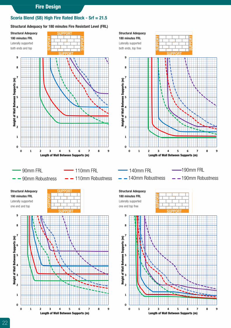
Scoria Blend (SB) High Fire Rated Block - Srf = 21.5
Structural Adequacy for 180 minutes Fire Resistant Level (FRL)
Fire Design
Structural Adequacy
180 minutes FRL
Laterally supported
both ends and top
Structural Adequacy
180 minutes FRL
Laterally supported
both ends, top free
SUPPORT
SUPPORTSU
PPOR
T
SUPP
ORT
SUPPORT
SUPPORT
SUPP
ORT
SUPP
ORT
0
1
2
3
4
5
6
7
8
9
0 1 2 3 4 5 6 7 8 9
Heig
ht o
f Wal
l Bet
wee
n Su
ppor
ts (m
)
Length of Wall Between Supports (m)
0
1
2
3
4
5
6
7
8
9
0 1 2 3 4 5 6 7 8 9
Heig
ht o
f Wal
l Bet
wee
n Su
ppor
ts (m
)
Length of Wall Between Supports (m)
90mm FRL 110mm FRL 140mm FRL 190mm FRL
90mm Robustness 110mm Robustness 140mm Robustness 190mm Robustness
Structural Adequacy
180 minutes FRL
Laterally supported
one end and top
Structural Adequacy
180 minutes FRL
Laterally supported
one end top free
SUPPORT
SUPPORT
SUPP
ORT
SUPP
ORT
SUPPORT
SUPPORT
SUPP
ORT
SUPP
ORT
0
1
2
3
4
5
6
7
8
9
0 1 2 3 4 5 6 7 8 9
Heig
ht o
f Wal
l Bet
wee
n Su
ppor
ts (m
)
Length of Wall Between Supports (m)
0
1
2
3
4
5
6
7
8
9
0 1 2 3 4 5 6 7 8 9
Heig
ht o
f Wal
l Bet
wee
n Su
ppor
ts (m
)
Length of Wall Between Supports (m)
22
Fire Design
Scoria Blend (SB) High Fire Rated Block - Srf = 19.7
Structural Adequacy for 240 minutes Fire Resistant Level (FRL)
Structural Adequacy
240 minutes FRL
Laterally supported
both ends and top
Structural Adequacy
240 minutes FRL
Laterally supported
both ends, top free
SUPPORT
SUPPORTSU
PPOR
T
SUPP
ORT
SUPPORT
SUPPORT
SUPP
ORT
SUPP
ORT
0
1
2
3
4
5
6
7
8
9
0 1 2 3 4 5 6 7 8 9
Heig
ht o
f Wal
l Bet
wee
n Su
ppor
ts (m
)
Length of Wall Between Supports (m)
0
1
2
3
4
5
6
7
8
9
0 1 2 3 4 5 6 7 8 9
Heig
ht o
f Wal
l Bet
wee
n Su
ppor
ts (m
)
Length of Wall Between Supports (m)
90mm FRL 110mm FRL 140mm FRL 190mm FRL
90mm Robustness 110mm Robustness 140mm Robustness 190mm Robustness
Structural Adequacy
240 minutes FRL
Laterally supported
one end and top
Structural Adequacy
240 minutes FRL
Laterally supported
one end top free
SUPPORT
SUPPORT
SUPP
ORT
SUPP
ORT
SUPPORT
SUPPORT
SUPP
ORT
SUPP
ORT
0
1
2
3
4
5
6
7
8
9
0 1 2 3 4 5 6 7 8 9
Heig
ht o
f Wal
l Bet
wee
n Su
ppor
ts (m
)
Length of Wall Between Supports (m)
0
1
2
3
4
5
6
7
8
9
0 1 2 3 4 5 6 7 8 9
Heig
ht o
f Wal
l Bet
wee
n Su
ppor
ts (m
)
Length of Wall Between Supports (m)
23
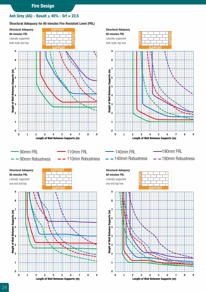
Ash Grey (AG) - Basalt > 45% - Srf = 22.5
Structural Adequacy for 60 minutes Fire Resistant Level (FRL)
Fire Design
Structural Adequacy
60 minutes FRL
Laterally supported
both ends and top
Structural Adequacy
60 minutes FRL
Laterally supported
both ends, top free
SUPPORT
SUPPORTSU
PPOR
T
SUPP
ORT
SUPPORT
SUPPORT
SUPP
ORT
SUPP
ORT
0
1
2
3
4
5
6
7
8
9
0 1 2 3 4 5 6 7 8 9
Heig
ht o
f Wal
l Bet
wee
n Su
ppor
ts (m
)
Length of Wall Between Supports (m)
0
1
2
3
4
5
6
7
8
9
0 1 2 3 4 5 6 7 8 9
Heig
ht o
f Wal
l Bet
wee
n Su
ppor
ts (m
)
Length of Wall Between Supports (m)
90mm FRL 110mm FRL 140mm FRL 190mm FRL
90mm Robustness 110mm Robustness 140mm Robustness 190mm Robustness
Structural Adequacy
60 minutes FRL
Laterally supported
one end and top
Structural Adequacy
60 minutes FRL
Laterally supported
one end top free
SUPPORT
SUPPORT
SUPP
ORT
SUPP
ORT
SUPPORT
SUPPORT
SUPP
ORT
SUPP
ORT
0
1
2
3
4
5
6
7
8
9
0 1 2 3 4 5 6 7 8 9
Heig
ht o
f Wal
l Bet
wee
n Su
ppor
ts (m
)
Length of Wall Between Supports (m)
0
1
2
3
4
5
6
7
8
9
0 1 2 3 4 5 6 7 8 9
Heig
ht o
f Wal
l Bet
wee
n Su
ppor
ts (m
)
Length of Wall Between Supports (m)
24
Fire Design
Ash Grey (AG) - Basalt > 45% - Srf = 21.5
Structural Adequacy for 90 minutes Fire Resistant Level (FRL)
Structural Adequacy
90 minutes FRL
Laterally supported
both ends and top
Structural Adequacy
90 minutes FRL
Laterally supported
both ends, top free
SUPPORT
SUPPORTSU
PPOR
T
SUPP
ORT
SUPPORT
SUPPORT
SUPP
ORT
SUPP
ORT
0
1
2
3
4
5
6
7
8
9
0 1 2 3 4 5 6 7 8 9
Heig
ht o
f Wal
l Bet
wee
n Su
ppor
ts (m
)
Length of Wall Between Supports (m)
0
1
2
3
4
5
6
7
8
9
0 1 2 3 4 5 6 7 8 9
Heig
ht o
f Wal
l Bet
wee
n Su
ppor
ts (m
)
Length of Wall Between Supports (m)
90mm FRL 110mm FRL 140mm FRL 190mm FRL
90mm Robustness 110mm Robustness 140mm Robustness 190mm Robustness
Structural Adequacy
90 minutes FRL
Laterally supported
one end and top
Structural Adequacy
90 minutes FRL
Laterally supported
one end top free
SUPPORT
SUPPORT
SUPP
ORT
SUPP
ORT
SUPPORT
SUPPORT
SUPP
ORT
SUPP
ORT
0
1
2
3
4
5
6
7
8
9
0 1 2 3 4 5 6 7 8 9
Heig
ht o
f Wal
l Bet
wee
n Su
ppor
ts (m
)
Length of Wall Between Supports (m)
0
1
2
3
4
5
6
7
8
9
0 1 2 3 4 5 6 7 8 9
Heig
ht o
f Wal
l Bet
wee
n Su
ppor
ts (m
)
Length of Wall Between Supports (m)
25
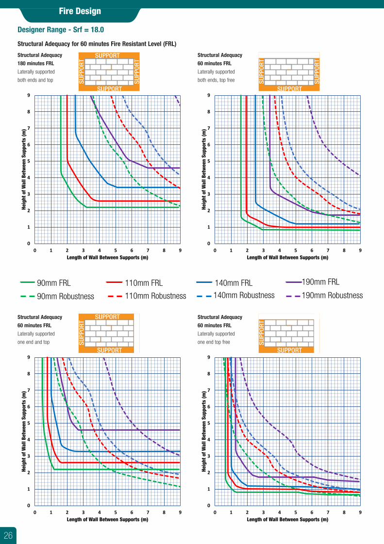
Designer Range - Srf = 18.0
Structural Adequacy for 60 minutes Fire Resistant Level (FRL)
Fire Design
Structural Adequacy
180 minutes FRL
Laterally supported
both ends and top
Structural Adequacy
60 minutes FRL
Laterally supported
both ends, top free
SUPPORT
SUPPORTSU
PPOR
T
SUPP
ORT
SUPPORT
SUPPORT
SUPP
ORT
SUPP
ORT
0
1
2
3
4
5
6
7
8
9
0 1 2 3 4 5 6 7 8 9
Heig
ht o
f Wal
l Bet
wee
n Su
ppor
ts (m
)
Length of Wall Between Supports (m)
0
1
2
3
4
5
6
7
8
9
0 1 2 3 4 5 6 7 8 9
Heig
ht o
f Wal
l Bet
wee
n Su
ppor
ts (m
)
Length of Wall Between Supports (m)
90mm FRL 110mm FRL 140mm FRL 190mm FRL
90mm Robustness 110mm Robustness 140mm Robustness 190mm Robustness
Structural Adequacy
60 minutes FRL
Laterally supported
one end and top
Structural Adequacy
60 minutes FRL
Laterally supported
one end top free
SUPPORT
SUPPORT
SUPP
ORT
SUPP
ORT
SUPPORT
SUPPORT
SUPP
ORT
SUPP
ORT
0
1
2
3
4
5
6
7
8
9
0 1 2 3 4 5 6 7 8 9
Heig
ht o
f Wal
l Bet
wee
n Su
ppor
ts (m
)
Length of Wall Between Supports (m)
0
1
2
3
4
5
6
7
8
9
0 1 2 3 4 5 6 7 8 9
Heig
ht o
f Wal
l Bet
wee
n Su
ppor
ts (m
)
Length of Wall Between Supports (m)
26
Fire Design
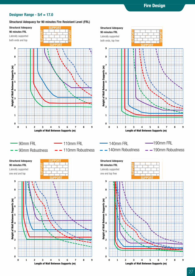
Designer Range - Srf = 17.0
Structural Adequacy for 90 minutes Fire Resistant Level (FRL)
Structural Adequacy
90 minutes FRL
Laterally supported
both ends and top
Structural Adequacy
90 minutes FRL
Laterally supported
both ends, top free
SUPPORT
SUPPORTSU
PPOR
T
SUPP
ORT
SUPPORT
SUPPORT
SUPP
ORT
SUPP
ORT
0
1
2
3
4
5
6
7
8
9
0 1 2 3 4 5 6 7 8 9
Heig
ht o
f Wal
l Bet
wee
n Su
ppor
ts (m
)
Length of Wall Between Supports (m)
0
1
2
3
4
5
6
7
8
9
0 1 2 3 4 5 6 7 8 9
Heig
ht o
f Wal
l Bet
wee
n Su
ppor
ts (m
)
Length of Wall Between Supports (m)
90mm FRL 110mm FRL 140mm FRL 190mm FRL
90mm Robustness 110mm Robustness 140mm Robustness 190mm Robustness
Structural Adequacy
90 minutes FRL
Laterally supported
one end and top
Structural Adequacy
90 minutes FRL
Laterally supported
one end top free
SUPPORT
SUPPORT
SUPP
ORT
SUPP
ORT
SUPPORT
SUPPORT
SUPP
ORT
SUPP
ORT
0
1
2
3
4
5
6
7
8
9
0 1 2 3 4 5 6 7 8 9
Heig
ht o
f Wal
l Bet
wee
n Su
ppor
ts (m
)
Length of Wall Between Supports (m)
0
1
2
3
4
5
6
7
8
9
0 1 2 3 4 5 6 7 8 9
Heig
ht o
f Wal
l Bet
wee
n Su
ppor
ts (m
)
Length of Wall Between Supports (m)
27
Fire Design
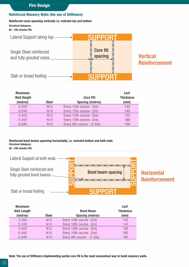
Reinforced Masonry Walls (the use of Stiffeners)
Reinforced cores spanning vertically i.e. restraint top and bottomStructural Adequacy
60 - 240 minutes FRL
Reinforced bond beams spanning horizontally, i.e. restraint bottom and both endsStructural Adequacy
60 - 240 minutes FRL
SUPPORT
SUPPORTSU
PPOR
T
SUPP
ORT
Core fillspacing
Lateral Support along top
Single Steel reinforcedand fully grouted cores
Slab or broad footing
SUPPORT
SUPPORT
SUPP
ORT
SUPP
ORT
Bond beam spacing
Slab or broad footing
Single Steel reinforced andfully grouted bond beams
Lateral Support at both ends
Vertical Reinforcement
Horizontal Reinforcement
Note: The use of Stiffeners implementing partial core fill is the most economical way to build masonry walls.
Maximum Leaf Wall Height Core Fill Thickness (metres) Steel Spacing (metres) (mm)
4.000 N12 Every 10th course- (2m) 1405.040 N16 Every 10th course- (2m) 1404.800 N12 Every 10th course- (2m) 1906.400 N16 Every 10th course- (2m) 1906.840 N16 Every 8th course - (1.6m) 190
Maximum Leaf Wall Length Bond Beam Thickness
(metres) Steel Spacing (metres) (mm) 4.000 N12 Every 10th course- (2m) 1405.040 N16 Every 10th course- (2m) 1404.800 N12 Every 10th course- (2m) 1906.400 N16 Every 10th course- (2m) 1906.840 N16 Every 8th course - (1.6m) 190
28
Fire Design
Walls Restrained at Top (Unrestrained Ends)Walls without restraint to the ends, but with lateral restraint along their top have maximum heights irrespective of their length as detailed in the following table. (Most doorways and windows create free ends).
SUPPORT
SUPPORT
SUPP
ORT
SUPP
ORT
Material Thickness
60 90 120 180 240Fire Rated Block - Scoria Blend (SB) 90mm 2.430 2.430 2.430 2.430 2.364
110mm 2.970 2.970 2.970 2.970 2.889140mm 3.780 3.780 3.780 3.780 3.677
Scoria Quick Brick (SB) 190mm 5.130 5.130 5.130 5.130 4.991
90mm 2.430 2.430 2.400 2.160 2.040110mm 2.970 2.970 2.933 2.640 2.493140mm 3.780 3.780 3.733 3.360 3.173190mm 5.130 5.130 5.067 4.560 4.307
90mm 2.160 2.040 1.920 1.860 1.800Designer Range 140mm 3.360 3.173 2.987 2.893 2.800
190mm 4.560 4.307 4.053 3.927 3.800
140mm 5.040 5.040 5.040 5.040 5.040190mm 6.840 6.840 6.840 6.840 6.840
*Governed by Robustness. Can be higher if supporting a slab. These heights can be exceeded when one or both ends are restrained as well as the top.
Maximum Wall Height (metres)Structural Adequacy (FRL minutes)
&
Ash Grey (AG)
Reinforced & Grout Filled
29
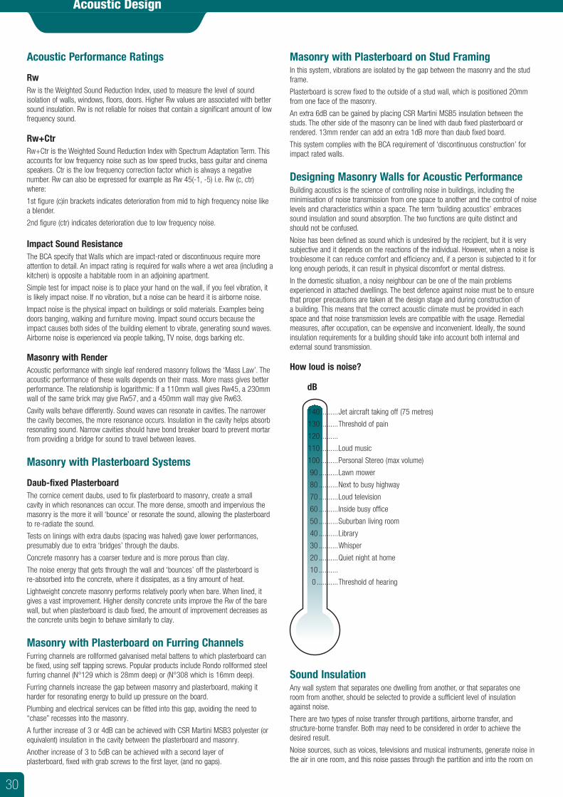
Acoustic Performance Ratings
RwRw is the Weighted Sound Reduction Index, used to measure the level of sound isolation of walls, windows, floors, doors. Higher Rw values are associated with better sound insulation. Rw is not reliable for noises that contain a significant amount of low frequency sound.
Rw+CtrRw+Ctr is the Weighted Sound Reduction Index with Spectrum Adaptation Term. This accounts for low frequency noise such as low speed trucks, bass guitar and cinema speakers. Ctr is the low frequency correction factor which is always a negative number. Rw can also be expressed for example as Rw 45(-1, -5) i.e. Rw (c, ctr) where:
1st figure (c)in brackets indicates deterioration from mid to high frequency noise like a blender.
2nd figure (ctr) indicates deterioration due to low frequency noise.
Impact Sound ResistanceThe BCA specify that Walls which are impact-rated or discontinuous require more attention to detail. An impact rating is required for walls where a wet area (including a kitchen) is opposite a habitable room in an adjoining apartment.
Simple test for impact noise is to place your hand on the wall, if you feel vibration, it is likely impact noise. If no vibration, but a noise can be heard it is airborne noise.
Impact noise is the physical impact on buildings or solid materials. Examples being doors banging, walking and furniture moving. Impact sound occurs because the impact causes both sides of the building element to vibrate, generating sound waves. Airborne noise is experienced via people talking, TV noise, dogs barking etc.
Masonry with RenderAcoustic performance with single leaf rendered masonry follows the ‘Mass Law’. The acoustic performance of these walls depends on their mass. More mass gives better performance. The relationship is logarithmic: If a 110mm wall gives Rw45, a 230mm wall of the same brick may give Rw57, and a 450mm wall may give Rw63.
Cavity walls behave differently. Sound waves can resonate in cavities. The narrower the cavity becomes, the more resonance occurs. Insulation in the cavity helps absorb resonating sound. Narrow cavities should have bond breaker board to prevent mortar from providing a bridge for sound to travel between leaves.
Masonry with Plasterboard Systems
Daub-fixed PlasterboardThe cornice cement daubs, used to fix plasterboard to masonry, create a small cavity in which resonances can occur. The more dense, smooth and impervious the masonry is the more it will ‘bounce’ or resonate the sound, allowing the plasterboard to re-radiate the sound.
Tests on linings with extra daubs (spacing was halved) gave lower performances, presumably due to extra ‘bridges’ through the daubs.
Concrete masonry has a coarser texture and is more porous than clay.
The noise energy that gets through the wall and ‘bounces’ off the plasterboard is re-absorbed into the concrete, where it dissipates, as a tiny amount of heat.
Lightweight concrete masonry performs relatively poorly when bare. When lined, it gives a vast improvement. Higher density concrete units improve the Rw of the bare wall, but when plasterboard is daub fixed, the amount of improvement decreases as the concrete units begin to behave similarly to clay.
Masonry with Plasterboard on Furring ChannelsFurring channels are rollformed galvanised metal battens to which plasterboard can be fixed, using self tapping screws. Popular products include Rondo rollformed steel furring channel (N°129 which is 28mm deep) or (N°308 which is 16mm deep).
Furring channels increase the gap between masonry and plasterboard, making it harder for resonating energy to build up pressure on the board.
Plumbing and electrical services can be fitted into this gap, avoiding the need to “chase” recesses into the masonry.
A further increase of 3 or 4dB can be achieved with CSR Martini MSB3 polyester (or equivalent) insulation in the cavity between the plasterboard and masonry.
Another increase of 3 to 5dB can be achieved with a second layer of plasterboard, fixed with grab screws to the first layer, (and no gaps).
Masonry with Plasterboard on Stud FramingIn this system, vibrations are isolated by the gap between the masonry and the stud frame.
Plasterboard is screw fixed to the outside of a stud wall, which is positioned 20mm from one face of the masonry.
An extra 6dB can be gained by placing CSR Martini MSB5 insulation between the studs. The other side of the masonry can be lined with daub fixed plasterboard or rendered. 13mm render can add an extra 1dB more than daub fixed board.
This system complies with the BCA requirement of ‘discontinuous construction’ for impact rated walls.
Designing Masonry Walls for Acoustic PerformanceBuilding acoustics is the science of controlling noise in buildings, including the minimisation of noise transmission from one space to another and the control of noise levels and characteristics within a space. The term ‘building acoustics’ embraces sound insulation and sound absorption. The two functions are quite distinct and should not be confused.
Noise has been defined as sound which is undesired by the recipient, but it is very subjective and it depends on the reactions of the individual. However, when a noise is troublesome it can reduce comfort and efficiency and, if a person is subjected to it for long enough periods, it can result in physical discomfort or mental distress.
In the domestic situation, a noisy neighbour can be one of the main problems experienced in attached dwellings. The best defence against noise must be to ensure that proper precautions are taken at the design stage and during construction of a building. This means that the correct acoustic climate must be provided in each space and that noise transmission levels are compatible with the usage. Remedial measures, after occupation, can be expensive and inconvenient. Ideally, the sound insulation requirements for a building should take into account both internal and external sound transmission.
How loud is noise?
dB
140 .........Jet aircraft taking off (75 metres)
130 .........Threshold of pain
120 .........
110 .........Loud music
100 .........Personal Stereo (max volume)
90 ..........Lawn mower
80 ..........Next to busy highway
70 ..........Loud television
60 ..........Inside busy office
50 ..........Suburban living room
40 ..........Library
30 ..........Whisper
20 ..........Quiet night at home
10 ..........
0 ...........Threshold of hearing
Sound InsulationAny wall system that separates one dwelling from another, or that separates one room from another, should be selected to provide a sufficient level of insulation against noise.
There are two types of noise transfer through partitions, airborne transfer, and structure-borne transfer. Both may need to be considered in order to achieve the desired result.
Noise sources, such as voices, televisions and musical instruments, generate noise in the air in one room, and this noise passes through the partition and into the room on
Acoustic Design
30
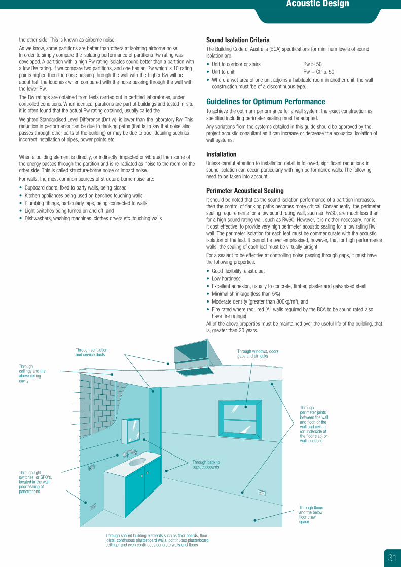
the other side. This is known as airborne noise.
As we know, some partitions are better than others at isolating airborne noise. In order to simply compare the isolating performance of partitions Rw rating was developed. A partition with a high Rw rating isolates sound better than a partition with a low Rw rating. If we compare two partitions, and one has an Rw which is 10 rating points higher, then the noise passing through the wall with the higher Rw will be about half the loudness when compared with the noise passing through the wall with the lower Rw.
The Rw ratings are obtained from tests carried out in certified laboratories, under controlled conditions. When identical partitions are part of buildings and tested in-situ, it is often found that the actual Rw rating obtained, usually called the
Weighted Standardised Level Difference (Dnt,w), is lower than the laboratory Rw. This reduction in performance can be due to flanking paths (that is to say that noise also passes through other parts of the building) or may be due to poor detailing such as incorrect installation of pipes, power points etc.
When a building element is directly, or indirectly, impacted or vibrated then some of the energy passes through the partition and is re-radiated as noise to the room on the other side. This is called structure-borne noise or impact noise.
For walls, the most common sources of structure-borne noise are:
• Cupboard doors, fixed to party walls, being closed• Kitchen appliances being used on benches touching walls• Plumbing fittings, particularly taps, being connected to walls• Light switches being turned on and off, and• Dishwashers, washing machines, clothes dryers etc. touching walls
Sound Isolation CriteriaThe Building Code of Australia (BCA) specifications for minimum levels of sound isolation are:
• Unit to corridor or stairs Rw ≥ 50• Unit to unit Rw + Ctr ≥ 50• Where a wet area of one unit adjoins a habitable room in another unit, the wall
construction must ‘be of a discontinuous type.’
Guidelines for Optimum PerformanceTo achieve the optimum performance for a wall system, the exact construction as specified including perimeter sealing must be adopted.
Any variations from the systems detailed in this guide should be approved by the project acoustic consultant as it can increase or decrease the acoustical isolation of wall systems.
InstallationUnless careful attention to installation detail is followed, significant reductions in sound isolation can occur, particularly with high performance walls. The following need to be taken into account.
Perimeter Acoustical SealingIt should be noted that as the sound isolation performance of a partition increases, then the control of flanking paths becomes more critical. Consequently, the perimeter sealing requirements for a low sound rating wall, such as Rw30, are much less than for a high sound rating wall, such as Rw60. However, it is neither necessary, nor is it cost effective, to provide very high perimeter acoustic sealing for a low rating Rw wall. The perimeter isolation for each leaf must be commensurate with the acoustic isolation of the leaf. It cannot be over emphasised, however, that for high performance walls, the sealing of each leaf must be virtually airtight.
For a sealant to be effective at controlling noise passing through gaps, it must have the following properties.
• Good flexibility, elastic set• Low hardness• Excellent adhesion, usually to concrete, timber, plaster and galvanised steel• Minimal shrinkage (less than 5%)• Moderate density (greater than 800kg/m3), and• Fire rated where required (All walls required by the BCA to be sound rated also
have fire ratings)All of the above properties must be maintained over the useful life of the building, that is, greater than 20 years.
Through windows, doors, gaps and air leaks
Throughceilings and the above ceiling cavity
Through floors and the below floor crawl space
Through light switches, or GPO's, located in the wall, poor sealing at penetrations
Through shared building elements such as floor boards, floor joists, continuous plasterboard walls, continuous plasterboard ceilings, and even continuous concrete walls and floors
Throughperimeter joints between the wall and floor, or the wall and ceiling (or underside of the floor slab) or wall junctions
Through ventilation and service ducts
Through back to back cupboards
Acoustic Design
31
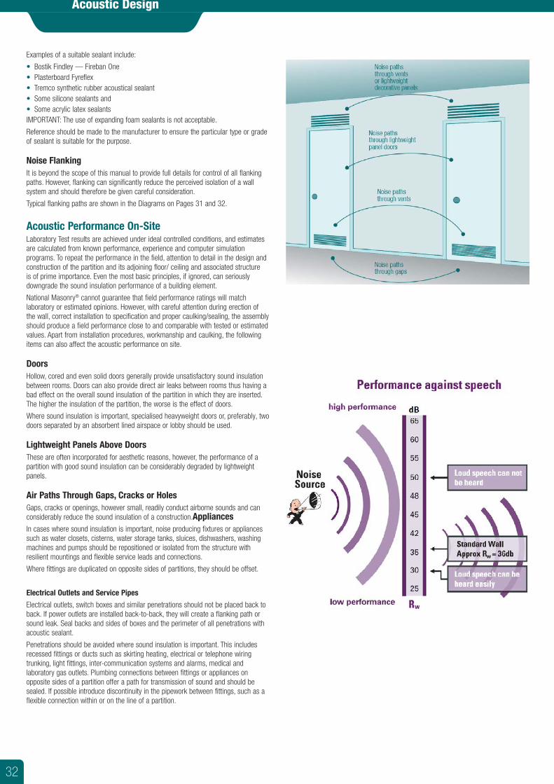
Examples of a suitable sealant include:
• Bostik Findley — Fireban One• Plasterboard Fyreflex• Tremco synthetic rubber acoustical sealant• Some silicone sealants and• Some acrylic latex sealantsIMPORTANT: The use of expanding foam sealants is not acceptable.
Reference should be made to the manufacturer to ensure the particular type or grade of sealant is suitable for the purpose.
Noise FlankingIt is beyond the scope of this manual to provide full details for control of all flanking paths. However, flanking can significantly reduce the perceived isolation of a wall system and should therefore be given careful consideration.
Typical flanking paths are shown in the Diagrams on Pages 31 and 32.
Acoustic Performance On-SiteLaboratory Test results are achieved under ideal controlled conditions, and estimates are calculated from known performance, experience and computer simulation programs. To repeat the performance in the field, attention to detail in the design and construction of the partition and its adjoining floor/ ceiling and associated structure is of prime importance. Even the most basic principles, if ignored, can seriously downgrade the sound insulation performance of a building element.
National Masonry® cannot guarantee that field performance ratings will match laboratory or estimated opinions. However, with careful attention during erection of the wall, correct installation to specification and proper caulking/sealing, the assembly should produce a field performance close to and comparable with tested or estimated values. Apart from installation procedures, workmanship and caulking, the following items can also affect the acoustic performance on site.
DoorsHollow, cored and even solid doors generally provide unsatisfactory sound insulation between rooms. Doors can also provide direct air leaks between rooms thus having a bad effect on the overall sound insulation of the partition in which they are inserted. The higher the insulation of the partition, the worse is the effect of doors.
Where sound insulation is important, specialised heavyweight doors or, preferably, two doors separated by an absorbent lined airspace or lobby should be used.
Lightweight Panels Above DoorsThese are often incorporated for aesthetic reasons, however, the performance of a partition with good sound insulation can be considerably degraded by lightweight panels.
Air Paths Through Gaps, Cracks or HolesGaps, cracks or openings, however small, readily conduct airborne sounds and can considerably reduce the sound insulation of a construction.AppliancesIn cases where sound insulation is important, noise producing fixtures or appliances such as water closets, cisterns, water storage tanks, sluices, dishwashers, washing machines and pumps should be repositioned or isolated from the structure with resilient mountings and flexible service leads and connections.
Where fittings are duplicated on opposite sides of partitions, they should be offset.
Electrical Outlets and Service Pipes
Electrical outlets, switch boxes and similar penetrations should not be placed back to back. If power outlets are installed back-to-back, they will create a flanking path or sound leak. Seal backs and sides of boxes and the perimeter of all penetrations with acoustic sealant.
Penetrations should be avoided where sound insulation is important. This includes recessed fittings or ducts such as skirting heating, electrical or telephone wiring trunking, light fittings, inter-communication systems and alarms, medical and laboratory gas outlets. Plumbing connections between fittings or appliances on opposite sides of a partition offer a path for transmission of sound and should be sealed. If possible introduce discontinuity in the pipework between fittings, such as a flexible connection within or on the line of a partition.
Acoustic Design
32
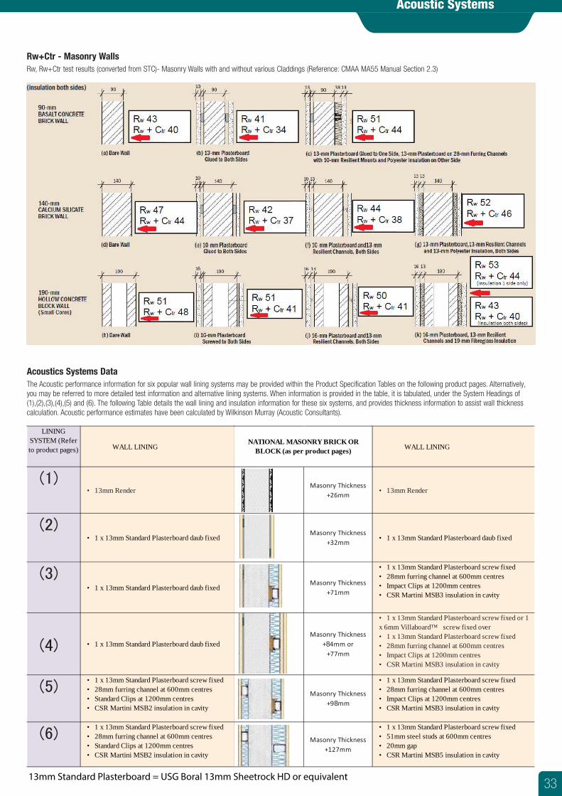
Acoustic Systems
Acoustics Systems DataThe Acoustic performance information for six popular wall lining systems may be provided within the Product Specification Tables on the following product pages. Alternatively, you may be referred to more detailed test information and alternative lining systems. When information is provided in the table, it is tabulated, under the System Headings of (1),(2),(3),(4),(5) and (6). The following Table details the wall lining and insulation information for these six systems, and provides thickness information to assist wall thickness calculation. Acoustic performance estimates have been calculated by Wilkinson Murray (Acoustic Consultants).
LINING SYSTEM (Refer to product pages) WALL LINING WALL LINING
(1)• 13mm Render
Masonry Thickness+26mm
• 13mm Render
(2)• 1 x 13mm Standard Plasterboard daub fixed
Masonry Thickness+32mm
• 1 x 13mm Standard Plasterboard daub fixed
(3)• 1 x 13mm Standard Plasterboard daub fixed
Masonry Thickness+71mm
• 1 x 13mm Standard Plasterboard screw fixed• 28mm furring channel at 600mm centres• Impact Clips at 1200mm centres• CSR Martini MSB3 insulation in cavity
(4) • 1 x 13mm Standard Plasterboard daub fixedMasonry Thickness
+84mm or+77mm
• 1 x 13mm Standard Plasterboard screw fixed or 1 x 6mm Villaboard™ screw fixed over• 1 x 13mm Standard Plasterboard screw fixed• 28mm furring channel at 600mm centres• Impact Clips at 1200mm centres• CSR Martini MSB3 insulation in cavity
(5)• 1 x 13mm Standard Plasterboard screw fixed• 28mm furring channel at 600mm centres• Standard Clips at 1200mm centres• CSR Martini MSB2 insulation in cavity
Masonry Thickness+98mm
• 1 x 13mm Standard Plasterboard screw fixed• 28mm furring channel at 600mm centres• Impact Clips at 1200mm centres• CSR Martini MSB3 insulation in cavity
(6)• 1 x 13mm Standard Plasterboard screw fixed• 28mm furring channel at 600mm centres• Standard Clips at 1200mm centres• CSR Martini MSB2 insulation in cavity
Masonry Thickness+127mm
• 1 x 13mm Standard Plasterboard screw fixed• 51mm steel studs at 600mm centres• 20mm gap• CSR Martini MSB5 insulation in cavity
NATIONAL MASONRY BRICK OR BLOCK (as per product pages)
13mm Standard Plasterboard = USG Boral 13mm Sheetrock HD or equivalent
Rw+Ctr - Masonry WallsRw, Rw+Ctr test results (converted from STC)- Masonry Walls with and without various Claddings (Reference: CMAA MA55 Manual Section 2.3)
33
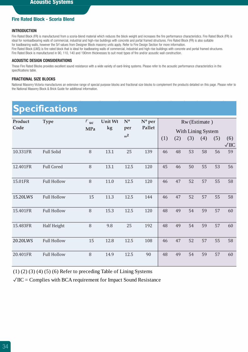
Acoustic Systems
Fire Rated Block - Scoria Blend
INTRODUCTIONFire Rated Block (FR) is manufactured from a scoria-blend material which reduces the block weight and increases the fire performance characteristics. Fire Rated Block (FR) is ideal for nonloadbearing walls of commercial, industrial and high-rise buildings with concrete and portal framed structures. Fire Rated Block (FR) is also suitablefor loadbearing walls, however the Srf values from Designer Block masonry units apply. Refer to Fire Design Section for more information.Fire Rated Block (LWS) is fire rated block that is ideal for loadbearing walls of commercial, industrial and high-rise buildings with concrete and portal framed structures. Fire Rated Block is manufactured in 90, 110, 140 and 190mm thicknesses to suit most types of fire and/or acoustic wall construction.
ACOUSTIC DESIGN CONSIDERATIONSThese Fire Rated Blocks provides excellent sound resistance with a wide variety of oard-lining systems. Please refer to the acoustic performance characteristics in the specifications table.
FRACTIONAL SIZE BLOCKSNational Masonry Victoria manufactures an extensive range of special purpose blocks and fractional size blocks to complement the products detailed on this page. Please refer to the National Masonry Block & Brick Guide for additional information.
(1) (2) (3) (4) (5) (6)✓IIC
(1) (2) (3) (4) (5) (6) Refer to preceding Table of Lining Systems✓IIC = Complies with BCA requirement for Impact Sound Resistance
48 49 54 59 57 6020.401FR Full Hollow 8 14.9 12.5 90
46 47 52 57 55 5820.20LWS Full Hollow 15 12.8 12.5 108
48 49 54 59 57 6015.483FR Half Height 8 9.8 25 192
48 49 54 59 57 6015.401FR Full Hollow 8 15.3 12.5 120
46 47 52 57 55 5815.20LWS Full Hollow 15 11.3 12.5 144
46 47 52 57 55 5815.01FR Full Hollow 8 11.0 12.5 120
45 46 50 55 53 5612.401FR Full Cored 8 13.1 12.5 120
53 58 56 59
With Lining System
10.331FR Full Solid 8 13.1 25 139 46 48
SpecificationsProduct Code
Type ƒ’ ucMPa
Unit Wt kg
Nºper
m2
Nº per Pallet
Rw (Estimate )
34
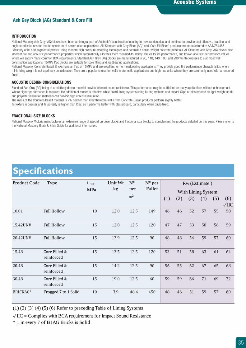
Acoustic Systems
Ash Gey Block (AG) Standard & Core Fill
INTRODUCTIONNational Masonry Ash Grey (AG) blocks have been an integral part of Australia’s construction industry for several decades, and continue to provide cost effective, practical and engineered solutions for the full spectrum of construction applications. All ‘Standard Ash Grey Block (AG)’ and ‘Core Fill Block’ products are manufactured to AS/NZS4455‘Masonry units and segmental pavers’ using modern high pressure moulding techniques and controlled dense-weight concrete materials. All Standard Ash Grey (AG) blocks haveinherent fire and acoustic performance properties which automatically allocates them ‘deemed-to-satisfy’ values for ire performance, and known acoustic performance values which will satisfy many common BCA requirements. Standard Ash Grey (AG) blocks are manufactured in 90, 110, 140, 190, and 290mm thicknesses to suit most wall construction applications. 15MPa f’uc blocks are suitable for core filling and loadbearing applications.National Masonry Concrete Basalt Bricks have an f’uc of 10MPa and are excellent for non-loadbearing applications. They provide good fire performance characteristics where minimising weight is not a primary consideration. They are a popular choice for walls in domestic applications and high rise units where they are commonly used with a rendered finish.
ACOUSTIC DESIGN CONSIDERATIONSStandard Ash Grey (AG) being of a relatively dense material provide inherent sound resistance. This performance may be sufficient for many applications without enhancement.Where higher performance is required, the addition of render is effective while board-lining systems using furring systems and Impact Clips or plasterboard on light-weight studsand polyester insulation materials can provide high acoustic insulation. The mass of the Concrete-Basalt material is 7% heavier than Clay therefore walls from Concrete-Basalt products perform slightly better.Its texture is coarser and its porosity is higher than Clay, so it performs better with plasterboard, particularly when daub-fixed.
FRACTIONAL SIZE BLOCKSNational Masonry Victoria manufactures an extensive range of special purpose blocks and fractional size blocks to complement the products detailed on this page. Please refer to the National Masonry Block & Brick Guide for additional information.
(1) (2) (3) (4) (5) (6)✓IIC
10.01 Full Hollow 10 12.0 12.5 149 46 46 52 57 55 58
15.42UNV Full Hollow 15 12.8 12.5 120 47 47 53 58 56 59
20.42UNV Full Hollow 15 13.9 12.5 90 48 48 54 59 57 60
15.48 Core Filled & reinforced
15 13.5 12.5 120 53 51 58 63 61 64
20.48 Core Filled & reinforced
15 14.2 12.5 90 56 55 62 67 65 68
30.48 Core Filled & reinforced
15 19.0 12.5 60 59 59 66 71 69 72
BRICKAG* Frogged 7 to 1 Solid 10 3.9 48.4 450 48 46 51 59 57 60
(1) (2) (3) (4) (5) (6) Refer to preceding Table of Lining Systems✓IIC = Complies with BCA requirement for Impact Sound Resistance* 1 in every 7 of B1AG Bricks is Solid
SpecificationsProduct Code Type ƒ’ uc
MPaUnit Wt
kgNºper
m2
Nº per Pallet
Rw (Estimate )
With Lining System
35
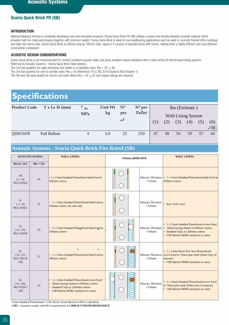
Acoustic Systems
Scoria Quick Brick FR (SB)
INTRODUCTIONNational Masonry Victoria is constantly developing new and innovative products. Scoria Quick Brick FR (SB) utilises a unique low-density blended concrete material which provides high fire rated performance together with minimum weight. Scoria Quick Brick is ideal for non-loadbearing applications such as walls in concrete framed office buildings and high-rise home units. Scoria Quick Brick is 230mm long by 162mm high, equal to 2 courses of standard brick with mortar, making them a highly efficient and cost-effective construction component.
ACOUSTIC DESIGN CONSIDERATIONSScoria Quick Brick is not recommended for cement rendered acoustic walls, but gives excellent sound resistance with a wide variety of tested board-lining systems. Referring to Acoustic Systems - Scoria Quick Brick Table (below) :The 2nd test qualifies for walls enclosing vent shafts in a habitable room: Rw + Ctr > 40.The 3rd test qualifies for unit-to-corridor walls: Rw > 50 (Reference: F5.5, NC 2019 Guide to BCA Volume 1}The 4th and 5th tests qualify for unit-to-unit walls where Rw + Ctr > 50 and impact ratings are required.
(1) (2) (3) (4) (5) (6)✓IIC
QBRICKFR Full Hollow 4 6.8 25 250 47 48 56 59 57 60
With Lining System
SpecificationsProduct Code T x Lx H (mm) ƒ’ uc
MPaUnit Wt
kgNºper
m2
Nº per Pallet
Rw (Estimate )
WALL LINING WALL LINING
Rw (c, ctr) Rw + Ctr
48(-1, -6)
T621-05S2242 • 1 x 13mm Standard Plasterboard daub fixed at
500mm centresMasonry Thickness
+142mm• 1 x 13mm Standard Plasterboard daub fixed at 500mm centres
47(-1, -6)
T621-05S2141 • 1 x 13mm Standard Plasterboard daub fixed at
500mm centres one side onlyMasonry Thickness
+126mm • Bare Wall (vent)
55(-4, -10)
T621-05S2045 • 1 x 13mm Standard Plasterboard daub fixed at
500mm centresMasonry Thickness
+169mm
• 1 x 13mm Standard Plasterboard screw fixed• 28mm furring channel at 600mm centres• Standard Clips at 1200mm centres• CSR Martini MSB3 insulation in cavity
61(-4, -11)
T621-05S19✓IIC
51 • 1 x 13mm Standard Plasterboard daub fixed at 500mm centres
Masonry Thickness +229mm
• 1 x 13mm Boral Wet Area Plasterboard screw fixed to 70mm pine studs 20mm clear of masonry• CSR Martini MSB6 insulation in cavity
62(-4, -10)
T621-05S17✓IIC
52
• 1 x 13mm Standard Plasterboard screw fixed• 28mm furring channel at 600mm centres• Standard Clips at 1200mm centres• CSR Martini MSB2 insulation in cavity
Masonry Thickness +256mm
• 1 x 13mm Standard Plasterboard screw fixed to 70mm pine studs 20mm clear of masonry• CSR Martini MSB6 insulation in cavity
13mm Standard Plasterboard = USG Boral 13mm Sheetrock HD or equivalent✓IIC = Systems comply with BCA requirements for IMPACT SOUND RESISTANCE
ACOUSTIC RATING 110mm QBRICKFR
Acoustic Systems - Scoria Quick Brick Fire Rated (SB)
36
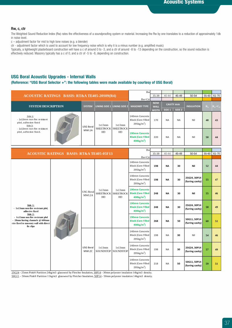
Acoustic Systems
Rw, c, ctrThe Weighted Sound Reduction Index (Rw) rates the effectiveness of a soundproofing system or material. Increasing the Rw by one translates to a reduction of approximately 1db in noise level.c – adjustment factor for mid to high tone noises (e.g. a blender)ctr - adjustment factor which is used to account for low frequency noise which is why it is a minus number (e.g. amplified music)Typically, a lightweight plasterboard construction will have a c of around 0 to -3, and a ctr of around -8 to -13 depending on the construction, so the sound reduction is effectively reduced. Masonry typically has a c of 0, and a ctr of -5 to -8, depending on construction.
USG Boral Acoustic Upgrades - Internal Walls (Reference: “USG Boral Selector +”: the following tables were made available by courtesy of USG Boral)
Rw35-39 40-44 45-49 50-54 55-60 61-70
Rw+Ctr
SIDE 1 SIDE 2
140mm Concrete Block (Core Filled
295kg/m2)170 NA NA Nil 48 43
190mm Concrete Block (Core Filled
400kg/m2)220 NA NA Nil 50 44
Rw35-39 40-44 45-49 50-54 55-60 61-70
Rw+Ctr
140mm Concrete Block (Core Filled
295kg/m2)198 NA 30 Nil 52 44
140mm Concrete Block (Core Filled
295kg/m2)198 NA 30
25G24, 30P14(furring cavity)
55 47
190mm Concrete Block (Core Filled
400kg/m2)248 NA 30 Nil 55 46
190mm Concrete Block (Core Filled
400kg/m2)248 NA 30
25G24, 30P14(furring cavity)
58 49
190mm Concrete Block (Core Filled
400kg/m2)268 NA 50
50G11, 50P14(furring cavity)
60 51
140mm Concrete Block (Core Filled
295kg/m2)198 NA 30 Nil 54 46
140mm Concrete Block (Core Filled
295kg/m2)198 NA 30
25G24, 30P14(furring cavity)
57 49
140mm Concrete Block (Core Filled
295kg/m2)218 NA 50
50G11, 50P14(furring cavity)
59 51
25G24 - 25mm Pink® Partition 24kg/m3 glasswool by Fletcher Insulation, 30P14 - 30mm polyester insulation 14kg/m3 density.50G11 – 50mm Pink® Partition 11kg/m3 glasswool by Fletcher Insulation, 50P14 - 50mm polyester insulation 14kg/m3 density.
ACOUSTIC RATINGS BASIS: RT&A TE405-20S09(R4)
SYSTEM DESCRIPTION SYSTEM LINING SIDE 1 LINING SIDE 2 MASONRY TYPENOM WALL
WIDTH
CAVITY mmINSULATION Rw Rw+Ctr
Side 1:- 1x13mm non fire resistant pbd, adhesive fixed Side 2:- 1x13mm non fire resistant pbd, adhesive fixed.
USG Boral MWI.1A
1x13mm SHEETROCK
HD
1x13mm SHEETROCK
HD
USG Boral MWI.2C
1x13mm SOUNDSTOP
1x13mm SOUNDSTOP
ACOUSTIC RATINGS BASIS: RT&A TE405-05F13
Side 1:- 1x13mm non-fire resistant pbd,
adhesive fixedSide 2:
- 1x13mm non fire resistant pbd- 28mm furring channels @ 600mm
ctrs fixed to masonry wall with direct fix clips
USG Boral MWI.2A
1x13mm SHEETROCK
HD
1x13mm SHEETROCK
HD
37
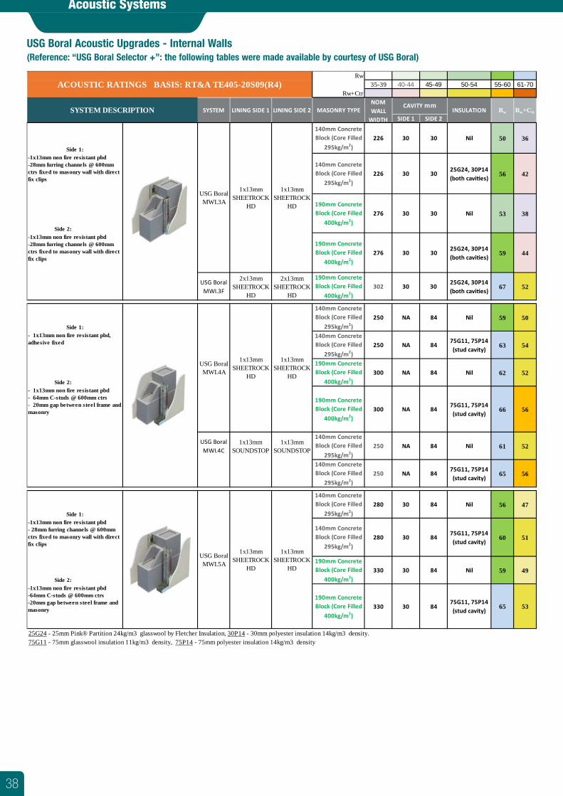
Acoustic Systems
USG Boral Acoustic Upgrades - Internal Walls (Reference: “USG Boral Selector +”: the following tables were made available by courtesy of USG Boral)
Rw35-39 40-44 45-49 50-54 55-60 61-70
Rw+Ctr
SIDE 1 SIDE 2
140mm Concrete Block (Core Filled
295kg/m2)226 30 30 Nil 50 36
140mm Concrete Block (Core Filled
295kg/m2)226 30 30
25G24, 30P14(both cavi�es)
56 42
Side 2:
190mm Concrete Block (Core Filled
400kg/m2)276 30 30 Nil 53 38
190mm Concrete Block (Core Filled
400kg/m2)276 30 30
25G24, 30P14(both cavi�es)
59 44
USG Boral MWI.3F
2x13mm SHEETROCK
HD
2x13mm SHEETROCK
HD
190mm Concrete Block (Core Filled
400kg/m2)302 30 30
25G24, 30P14(both cavi�es)
67 52
140mm Concrete Block (Core Filled
295kg/m2)250 NA 84 Nil 59 50
140mm Concrete Block (Core Filled
295kg/m2)250 NA 84
75G11, 75P14(stud cavity)
63 54
Side 2:
190mm Concrete Block (Core Filled
400kg/m2)300 NA 84 Nil 62 52
190mm Concrete Block (Core Filled
400kg/m2)300 NA 84
75G11, 75P14(stud cavity)
66 56
USG Boral MWI.4C
1x13mm SOUNDSTOP
1x13mm SOUNDSTOP
140mm Concrete Block (Core Filled
295kg/m2)250 NA 84 Nil 61 52
140mm Concrete Block (Core Filled
295kg/m2)250 NA 84
75G11, 75P14(stud cavity)
65 56
140mm Concrete Block (Core Filled
295kg/m2)280 30 84 Nil 56 47
140mm Concrete Block (Core Filled
295kg/m2)280 30 84
75G11, 75P14(stud cavity)
60 51
Side 2:
190mm Concrete Block (Core Filled
400kg/m2)330 30 84 Nil 59 49
190mm Concrete Block (Core Filled
400kg/m2)330 30 84
75G11, 75P14(stud cavity)
65 53
25G24 - 25mm Pink® Partition 24kg/m3 glasswool by Fletcher Insulation, 30P14 - 30mm polyester insulation 14kg/m3 density.75G11 - 75mm glasswool insulation 11kg/m3 density, 75P14 - 75mm polyester insulation 14kg/m3 density
1x13mm SHEETROCK
HD
-1x13mm non fire resistant pbd- 28mm furring channels @ 600mm ctrs fixed to masonry wall with direct fix clips
-1x13mm non fire resistant pbd-64mm C-studs @ 600mm ctrs-20mm gap between steel frame and masonry
Side 1:
USG Boral MWI.5A
1x13mm SHEETROCK
HD
Side 1:
USG Boral MWI.4A
1x13mm SHEETROCK
HD
1x13mm SHEETROCK
HD
- 1x13mm non fire resistant pbd, adhesive fixed
- 1x13mm non fire resistant pbd- 64mm C-studs @ 600mm ctrs- 20mm gap between steel frame and masonry
-1x13mm non fire resistant pbd-28mm furring channels @ 600mm ctrs fixed to masonry wall with direct fix clips
CAVITY mmINSULATION Rw Rw+Ctr
Side 1:
USG Boral MWI.3A
1x13mm SHEETROCK
HD
1x13mm SHEETROCK
HD
-1x13mm non fire resistant pbd-28mm furring channels @ 600mm ctrs fixed to masonry wall with direct fix clips
SYSTEM DESCRIPTION SYSTEM LINING SIDE 1 LINING SIDE 2 MASONRY TYPENOM WALL
WIDTH
ACOUSTIC RATINGS BASIS: RT&A TE405-20S09(R4)
38
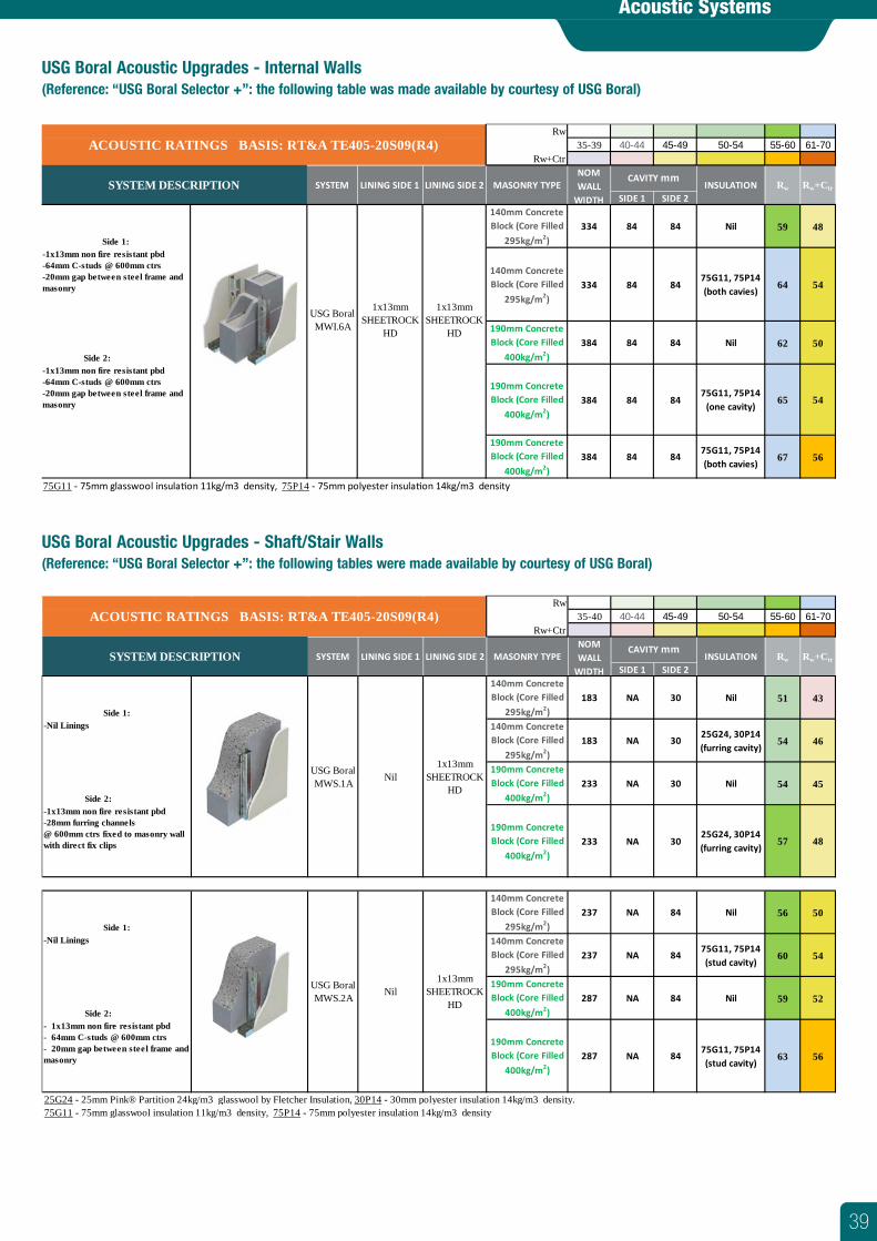
Acoustic Systems
USG Boral Acoustic Upgrades - Internal Walls (Reference: “USG Boral Selector +”: the following table was made available by courtesy of USG Boral)
Rw35-39 40-44 45-49 50-54 55-60 61-70
Rw+Ctr
SIDE 1 SIDE 2140mm Concrete Block (Core Filled
295kg/m2)334 84 84 Nil 59 48
140mm Concrete Block (Core Filled
295kg/m2)334 84 84
75G11, 75P14(both cavies)
64 54
Side 2:
190mm Concrete Block (Core Filled
400kg/m2)384 84 84 Nil 62 50
190mm Concrete Block (Core Filled
400kg/m2)384 84 84
75G11, 75P14(one cavity)
65 54
190mm Concrete Block (Core Filled
400kg/m2)384 84 84
75G11, 75P14(both cavies)
67 56
75G11 - 75mm glasswool insula�on 11kg/m3 density, 75P14 - 75mm polyester insula�on 14kg/m3 density
NOM WALL
WIDTH
CAVITY mmINSULATION Rw Rw+Ctr
ACOUSTIC RATINGS BASIS: RT&A TE405-20S09(R4)
SYSTEM DESCRIPTION SYSTEM LINING SIDE 1 LINING SIDE 2 MASONRY TYPE
Side 1:
USG Boral MWI.6A
1x13mm SHEETROCK
HD
1x13mm SHEETROCK
HD
-1x13mm non fire resistant pbd-64mm C-studs @ 600mm ctrs-20mm gap between steel frame and masonry
-1x13mm non fire resistant pbd-64mm C-studs @ 600mm ctrs-20mm gap between steel frame and masonry
USG Boral Acoustic Upgrades - Shaft/Stair Walls (Reference: “USG Boral Selector +”: the following tables were made available by courtesy of USG Boral)
Rw35-40 40-44 45-49 50-54 55-60 61-70
Rw+Ctr
SIDE 1 SIDE 2140mm Concrete Block (Core Filled
295kg/m2)183 NA 30 Nil 51 43
140mm Concrete Block (Core Filled
295kg/m2)183 NA 30
25G24, 30P14(furring cavity)
54 46
Side 2:
190mm Concrete Block (Core Filled
400kg/m2)233 NA 30 Nil 54 45
190mm Concrete Block (Core Filled
400kg/m2)233 NA 30
25G24, 30P14(furring cavity)
57 48
140mm Concrete Block (Core Filled
295kg/m2)237 NA 84 Nil 56 50
140mm Concrete Block (Core Filled
295kg/m2)237 NA 84
75G11, 75P14(stud cavity)
60 54
Side 2:
190mm Concrete Block (Core Filled
400kg/m2)287 NA 84 Nil 59 52
190mm Concrete Block (Core Filled
400kg/m2)287 NA 84
75G11, 75P14(stud cavity)
63 56
25G24 - 25mm Pink® Partition 24kg/m3 glasswool by Fletcher Insulation, 30P14 - 30mm polyester insulation 14kg/m3 density.75G11 - 75mm glasswool insulation 11kg/m3 density, 75P14 - 75mm polyester insulation 14kg/m3 density
Side 1:
USG Boral MWS.2A Nil
1x13mm SHEETROCK
HD
-Nil Linings
- 1x13mm non fire resistant pbd- 64mm C-studs @ 600mm ctrs- 20mm gap between steel frame and masonry
Side 1:
USG Boral MWS.1A Nil
1x13mm SHEETROCK
HD
-Nil Linings
-1x13mm non fire resistant pbd-28mm furring channels@ 600mm ctrs fixed to masonry wall with direct fix clips
MASONRY TYPENOM WALL
WIDTH
CAVITY mmINSULATION Rw Rw+Ctr
ACOUSTIC RATINGS BASIS: RT&A TE405-20S09(R4)
SYSTEM DESCRIPTION SYSTEM LINING SIDE 1 LINING SIDE 2
39
Victoria
Riding Boundary Road, Deer Park
Melbourne VIC 3023
Phone: (03) 9361 6400 Fax: (03) 9363 6008
South Queensland
62 Industrial Avenue, Wacol
Brisbane QLD 4076
Phone: (07) 3271 9292 Fax: (07) 3271 1815
Gold Coast
663 Pine Ridge Road, Biggera Waters
Gold Coast QLD 4216
Phone: (07) 5552 3300 Fax: (07) 5552 3399
New South Wales
65 Burleigh Street, Toronto
Lake Macquarie NSW 2283
Phone: (02) 4088 1888 Fax: (02) 4088 1899
Victoria
Riding Boundary Road, Deer Park
Melbourne VIC 3023
Phone: (03) 9361 6400 Fax: (03) 9363 6008
All pallets remain the property of National Masonry®
Online Booking Pickup
Use our Pallet Collection Form on our website.
www.nationalmasonry.com.au
Call to Arrange Pickup
Call your local branch during office hours.
(03) 9361 6443 or (03) 9361 6400
To find your closest National Masonry® stockist, to receive brochures or to learn more about our products, call us or visit our website at www.nationalmasonry.com.au
Colour variations occur from batch to batch. Colours shown are indicative only and should not be used for final selection. Products ordered should be chosen from actual samples current at the time of order and are subject to availability. Photographs in this brochure are only representative of National Masonry® products and the appearance and effect that may be achieved by their use. Samples, brochures and displays should be viewed as a guide only. Customers should ensure all delivered products are acceptable, and any concerns about products are made prior to laying. All prices are subject to availability and can be withdrawn or varied without notice. © Copyright National Masonry® Pty Ltd– all rights reserved 2013. Gardenwall® & Keystone Elite133® are registered trademarks of Keystone® Retaining Wall Systems Inc, use under licence by National Masonry®. National Masonry®, the National Masonry® logo, nationalmasonry.com.au, If these and other National Masonry® Pty Ltd trade marked terms are marked on their first occurrence in this information with a trade mark symbol (® or ™), these symbols indicate Australian registered or common law trade marks owned by National Masonry® Pty Ltd at the time this information was published. Such trade marks may also be registered or common law trade marks in other countries. Other product, company or service names may be trade marks or service marks of others. National Masonry® Pty Ltd ABN 94 155 064 136. Correct as at 04/08/2021. NAT0159 VIC Design Guide - Structural - Fire and Acoustic v17.