Embed Size (px)
Citation preview
MASS AND BALANCE
IN AIRCRAFT
KADİR BUHARALI
1
MASS AND BALANCE
INTRODUCTION
Deals with the loading of aircraft
Ensure that they are not overloaded or misloaded
2
MASS AND BALANCE
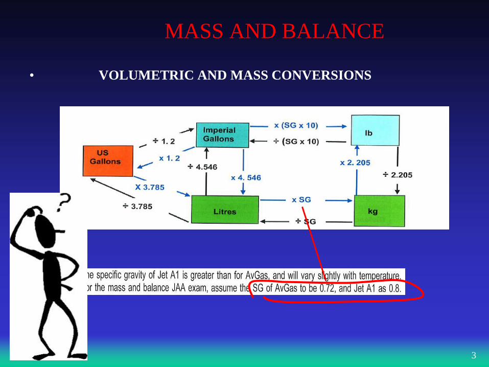
• VOLUMETRIC AND MASS CONVERSIONS
3
MASS AND BALANCE THEORY
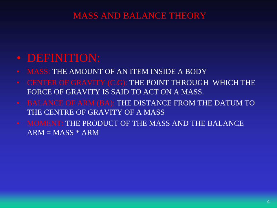
• DEFINITION: • MASS: THE AMOUNT OF AN ITEM INSIDE A BODY
• CENTER OF GRAVITY (C.G): THE POINT THROUGH WHICH THE
FORCE OF GRAVITY IS SAID TO ACT ON A MASS.
• BALANCE OF ARM (BA): THE DISTANCE FROM THE DATUM TO
THE CENTRE OF GRAVITY OF A MASS
• MOMENT: THE PRODUCT OF THE MASS AND THE BALANCE
ARM = MASS * ARM
4
MASS AND BALANCE THEORY
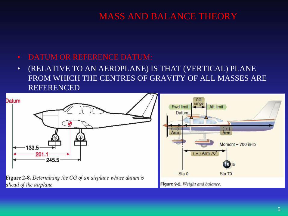
• DATUM OR REFERENCE DATUM:
• (RELATIVE TO AN AEROPLANE) IS THAT (VERTICAL) PLANE
FROM WHICH THE CENTRES OF GRAVITY OF ALL MASSES ARE
REFERENCED
5
FACTORS AFFECTING MASS AND BALANCE IN
AIRCRAFT
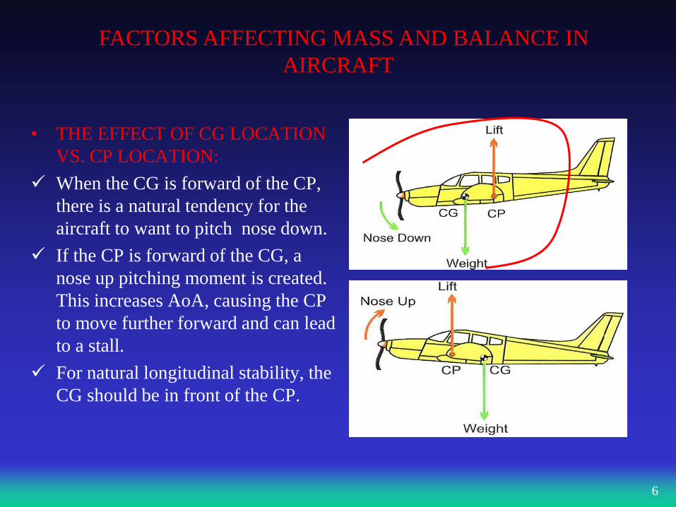
• THE EFFECT OF CG LOCATION
VS. CP LOCATION:
When the CG is forward of the CP,
there is a natural tendency for the
aircraft to want to pitch nose down.
If the CP is forward of the CG, a
nose up pitching moment is created.
This increases AoA, causing the CP
to move further forward and can lead
to a stall.
For natural longitudinal stability, the
CG should be in front of the CP.
6
FACTORS AFFECTING MASS AND BALANCE IN
AIRCRAFT
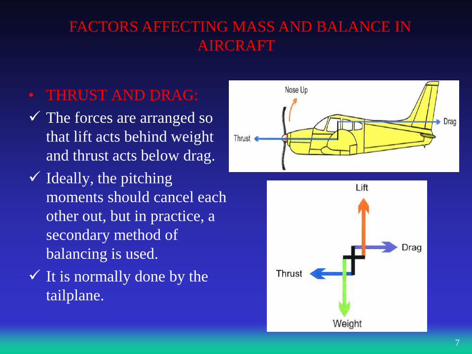
• THRUST AND DRAG:
The forces are arranged so
that lift acts behind weight
and thrust acts below drag.
Ideally, the pitching
moments should cancel each
other out, but in practice, a
secondary method of
balancing is used.
It is normally done by the
tailplane.
7

FACTORS AFFECTING MASS AND BALANCE IN
AIRCRAFT
• TAILPLANE:
• It supplies the force necessary to
balance any residual pitching
moment.
• Long Momemt Arm requires
smaller aerodynamic surface.
• It creates either a down force or
up force. At slow speed the force
is insufficient to balance.
• In these cases, the elevator is
deflected to increase or reduce the
forces. It creates drag, which is
referred to as Trim Drag.
8
Lift
FACTORS AFFECTING MASS AND BALANCE IN
AIRCRAFT
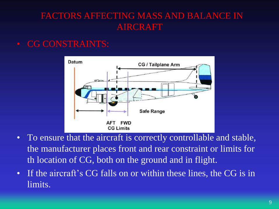
• CG CONSTRAINTS:
• To ensure that the aircraft is correctly controllable and stable,
the manufacturer places front and rear constraint or limits for
th location of CG, both on the ground and in flight.
• If the aircraft’s CG falls on or within these lines, the CG is in
limits.
9
FACTORS AFFECTING MASS AND BALANCE IN
AIRCRAFT
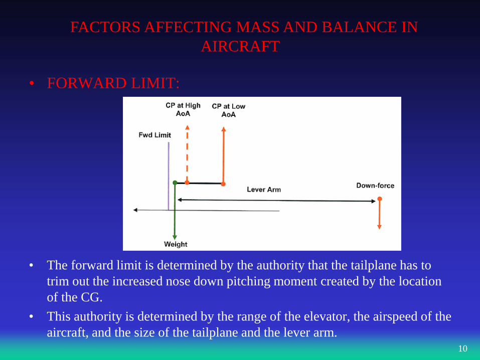
• FORWARD LIMIT:
• The forward limit is determined by the authority that the tailplane has to
trim out the increased nose down pitching moment created by the location
of the CG.
• This authority is determined by the range of the elevator, the airspeed of the
aircraft, and the size of the tailplane and the lever arm. 10
FACTORS AFFECTING MASS AND BALANCE IN
AIRCRAFT
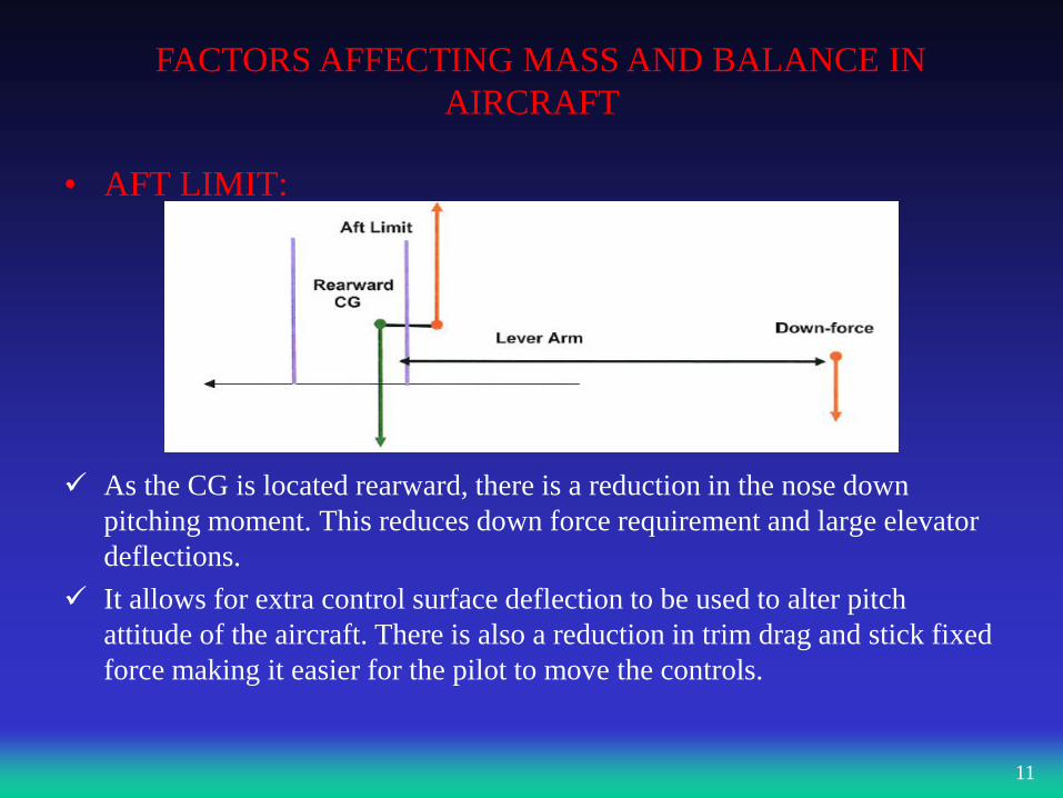
• AFT LIMIT:
As the CG is located rearward, there is a reduction in the nose down
pitching moment. This reduces down force requirement and large elevator
deflections.
It allows for extra control surface deflection to be used to alter pitch
attitude of the aircraft. There is also a reduction in trim drag and stick fixed
force making it easier for the pilot to move the controls.
11
FACTORS AFFECTING MASS AND BALANCE IN
AIRCRAFT
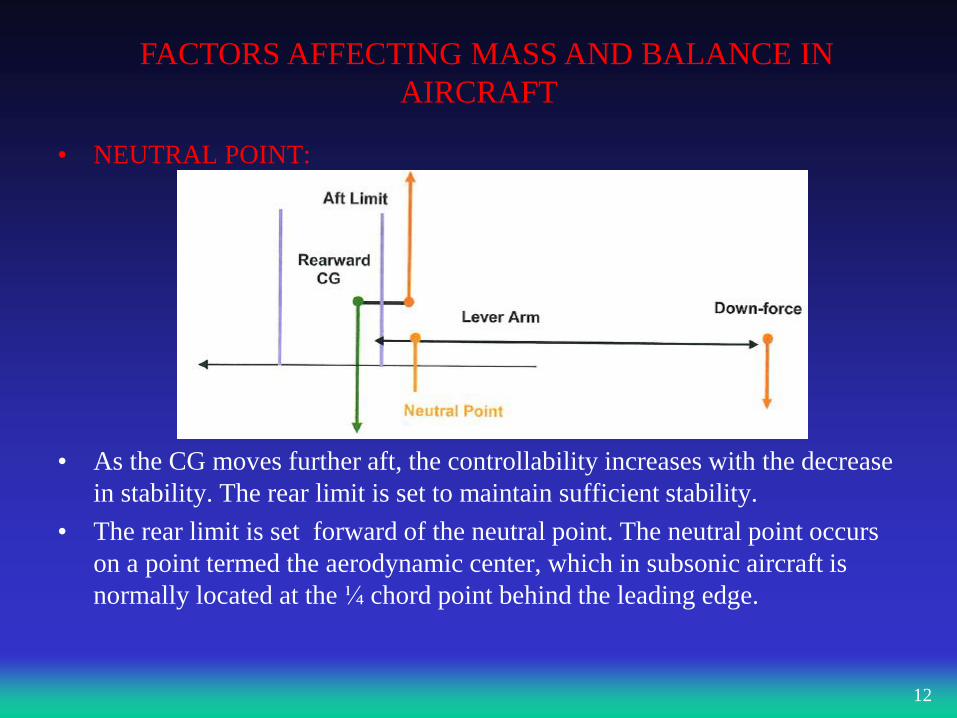
• NEUTRAL POINT:
• As the CG moves further aft, the controllability increases with the decrease
in stability. The rear limit is set to maintain sufficient stability.
• The rear limit is set forward of the neutral point. The neutral point occurs
on a point termed the aerodynamic center, which in subsonic aircraft is
normally located at the ¼ chord point behind the leading edge.
12
FACTORS AFFECTING MASS AND BALANCE IN
AIRCRAFT
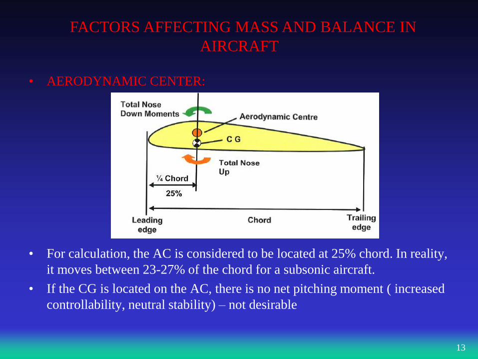
• AERODYNAMIC CENTER:
• For calculation, the AC is considered to be located at 25% chord. In reality,
it moves between 23-27% of the chord for a subsonic aircraft.
• If the CG is located on the AC, there is no net pitching moment ( increased
controllability, neutral stability) – not desirable
13
FACTORS AFFECTING MASS AND BALANCE IN
AIRCRAFT
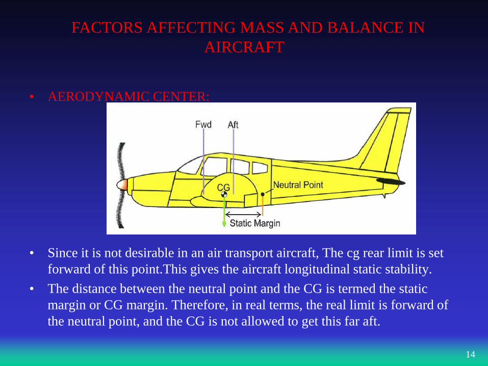
• AERODYNAMIC CENTER:
• Since it is not desirable in an air transport aircraft, The cg rear limit is set
forward of this point.This gives the aircraft longitudinal static stability.
• The distance between the neutral point and the CG is termed the static
margin or CG margin. Therefore, in real terms, the real limit is forward of
the neutral point, and the CG is not allowed to get this far aft.
14
FACTORS AFFECTING MASS AND BALANCE IN
AIRCRAFT
• FACTORS AFFECTING THE LONGITUDINAL CG POSITION IN
FLIGHT:
Fuel consumption
Flap extension / retraction
Gear extension / retraction
Cargo movement
Passenger / crew movement
15
FACTORS AFFECTING MASS AND BALANCE IN
AIRCRAFT
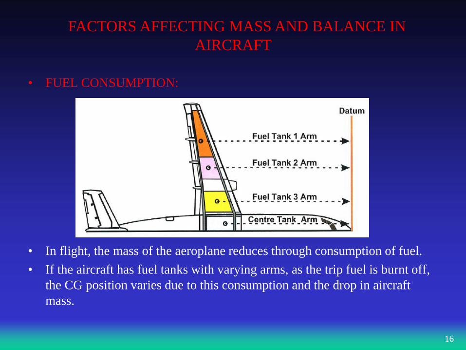
• FUEL CONSUMPTION:
• In flight, the mass of the aeroplane reduces through consumption of fuel.
• If the aircraft has fuel tanks with varying arms, as the trip fuel is burnt off,
the CG position varies due to this consumption and the drop in aircraft
mass.
16
FACTORS AFFECTING MASS AND BALANCE IN
AIRCRAFT
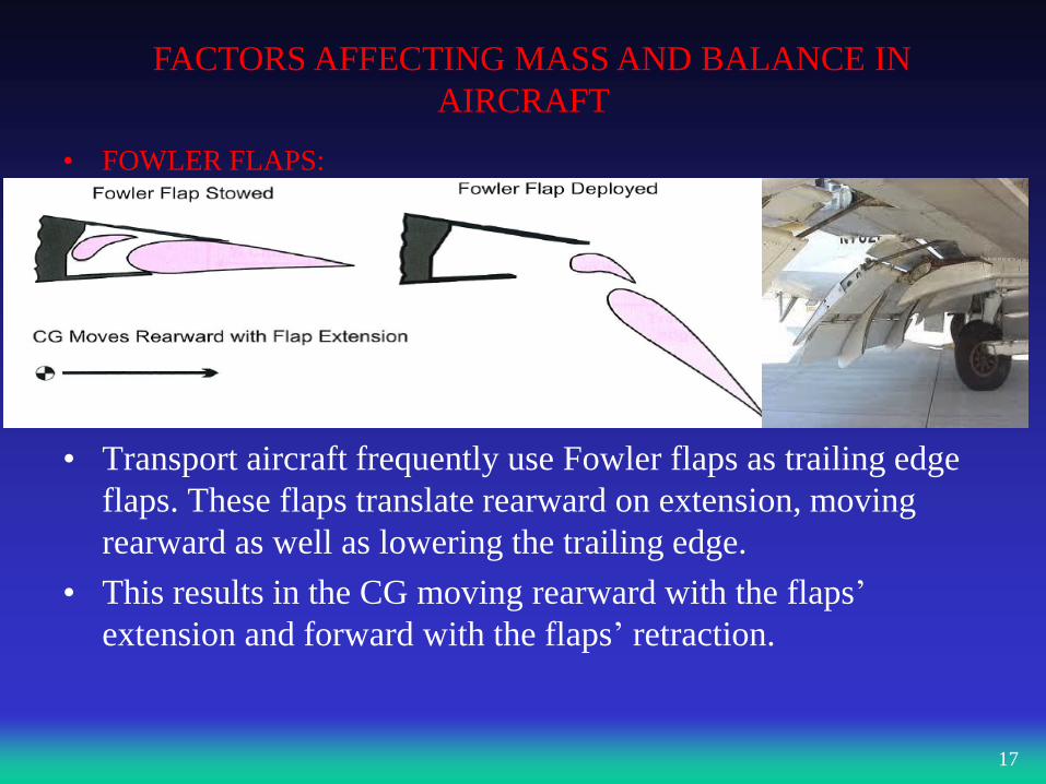
• FOWLER FLAPS:
• Transport aircraft frequently use Fowler flaps as trailing edge
flaps. These flaps translate rearward on extension, moving
rearward as well as lowering the trailing edge.
• This results in the CG moving rearward with the flaps’
extension and forward with the flaps’ retraction.
17
FACTORS AFFECTING MASS AND BALANCE IN
AIRCRAFT
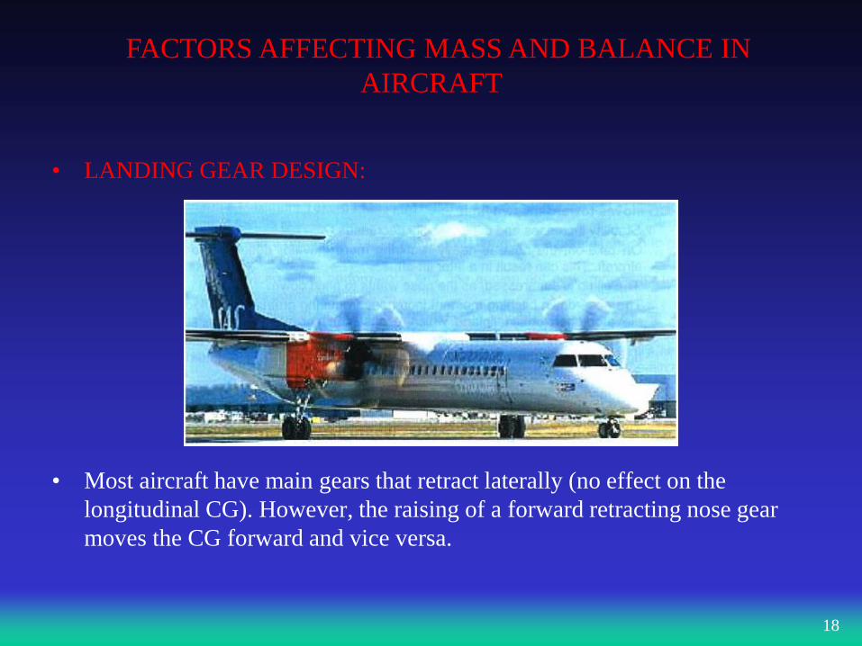
• LANDING GEAR DESIGN:
• Most aircraft have main gears that retract laterally (no effect on the
longitudinal CG). However, the raising of a forward retracting nose gear
moves the CG forward and vice versa.
18
FACTORS AFFECTING MASS AND BALANCE IN
AIRCRAFT
• CARGO:
• When an aircraft is loaded, The CG and mass must be within prescribed
limits of the aeroplane. If the cargo should shift in flight, the aircraft can
become either too stable or uncontrollable .
• Additionaly, cabin crew and passenger movements have an effect on the
trim of the aeroplane .
• THREE CG POINTS THAT MUST BE CALCULATED:
• If the aircraft is not overloaded, The CG may fall on or between the CG
limits. However, as the aircraft’s CG location moves with the consumption
of fuel, prior to any flight,
• the aircraft’s calculated Take-Off Mass (TOM),
• Landing Mass (LM),
• Zero Fuel Mass (ZFM)
• and corresponding CG s must be compared to the limits.
19
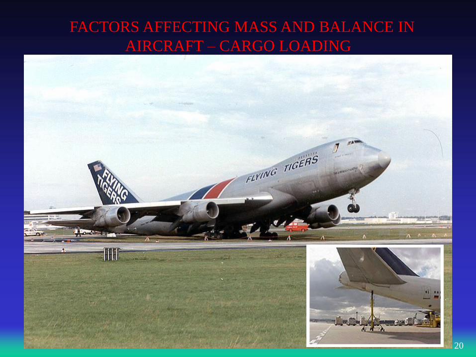
FACTORS AFFECTING MASS AND BALANCE IN
AIRCRAFT – CARGO LOADING
• CARGO:
•
20
FACTORS AFFECTING
MASS AND BALANCE IN
AIRCRAFT
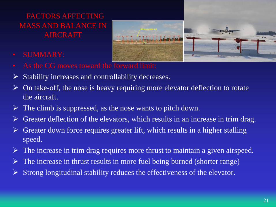
• SUMMARY:
• As the CG moves toward the forward limit:
Stability increases and controllability decreases.
On take-off, the nose is heavy requiring more elevator deflection to rotate
the aircraft.
The climb is suppressed, as the nose wants to pitch down.
Greater deflection of the elevators, which results in an increase in trim drag.
Greater down force requires greater lift, which results in a higher stalling
speed.
The increase in trim drag requires more thrust to maintain a given airspeed.
The increase in thrust results in more fuel being burned (shorter range)
Strong longitudinal stability reduces the effectiveness of the elevator.
21
FACTORS AFFECTING MASS AND BALANCE IN
AIRCRAFT
• As the CG moves toward the aft limit:
Stability decreases and controllability increases.
On take-off, the nose is lighter, requiring less elevator deflection. The
aircraft rotates more rapidly than expected.
The down force required from the elevator reduces. ( less drag)
The reduction in drag, requires less thrust.
Less thrust results in fuel flow reducing and range increase.
The decreased down force, which results in a lower stalling speed.
In the event of a landing climb ( go around), the aircraft’s nose rotates more
easiliy.
22
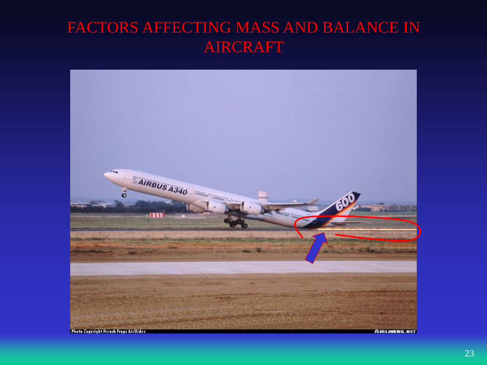
FACTORS AFFECTING MASS AND BALANCE IN
AIRCRAFT
23
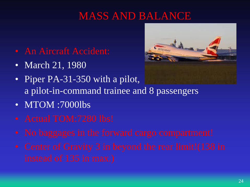
MASS AND BALANCE
• An Aircraft Accident:
• March 21, 1980
• Piper PA-31-350 with a pilot,
a pilot-in-command trainee and 8 passengers
• MTOM :7000lbs
• Actual TOM:7280 lbs!
• No baggages in the forward cargo compartment!
• Center of Gravity 3 in beyond the rear limit!(138 in
instead of 135 in max.)
24
FACTORS AFFECTING MASS AND BALANCE IN
AIRCRAFT
25
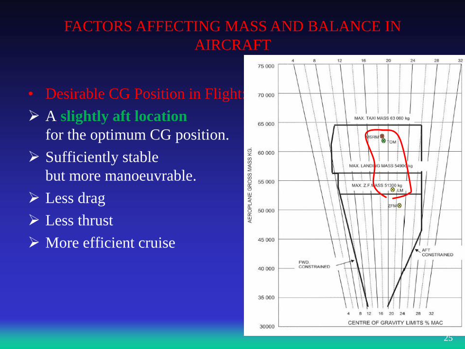
• Desirable CG Position in Flight:
A slightly aft location
for the optimum CG position.
Sufficiently stable
but more manoeuvrable.
Less drag
Less thrust
More efficient cruise
FACTORS AFFECTING MASS AND BALANCE IN
AIRCRAFT
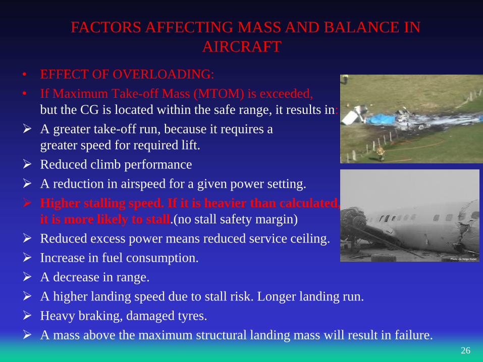
• EFFECT OF OVERLOADING:
• If Maximum Take-off Mass (MTOM) is exceeded,
but the CG is located within the safe range, it results in:
A greater take-off run, because it requires a
greater speed for required lift.
Reduced climb performance
A reduction in airspeed for a given power setting.
Higher stalling speed. If it is heavier than calculated,
it is more likely to stall.(no stall safety margin)
Reduced excess power means reduced service ceiling.
Increase in fuel consumption.
A decrease in range.
A higher landing speed due to stall risk. Longer landing run.
Heavy braking, damaged tyres.
A mass above the maximum structural landing mass will result in failure.
26
FACTORS AFFECTING MASS AND BALANCE IN
AIRCRAFT
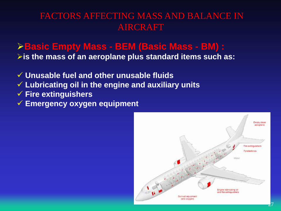
Basic Empty Mass - BEM (Basic Mass - BM) : is the mass of an aeroplane plus standard items such as:
Unusable fuel and other unusable fluids
Lubricating oil in the engine and auxiliary units
Fire extinguishers
Emergency oxygen equipment
27
MASS DEFINITIONS AND LIMITATIONS
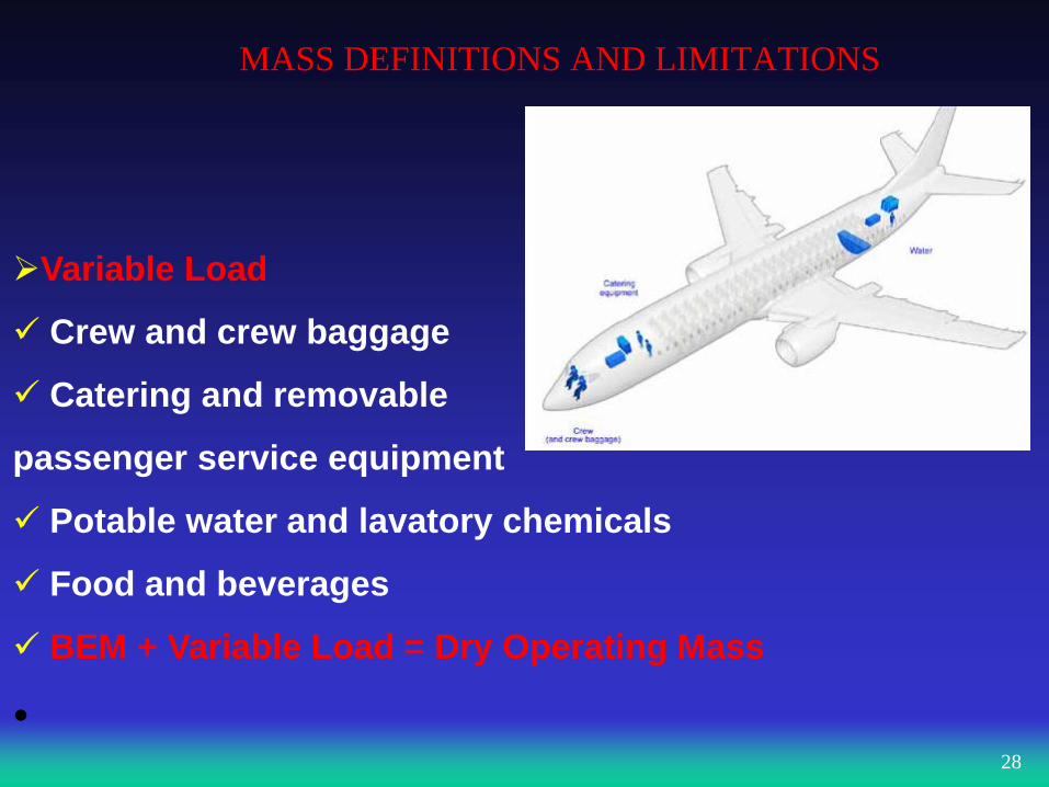
Variable Load
Crew and crew baggage
Catering and removable
passenger service equipment
Potable water and lavatory chemicals
Food and beverages
BEM + Variable Load = Dry Operating Mass
• 28
MASS DEFINITIONS AND LIMITATIONS
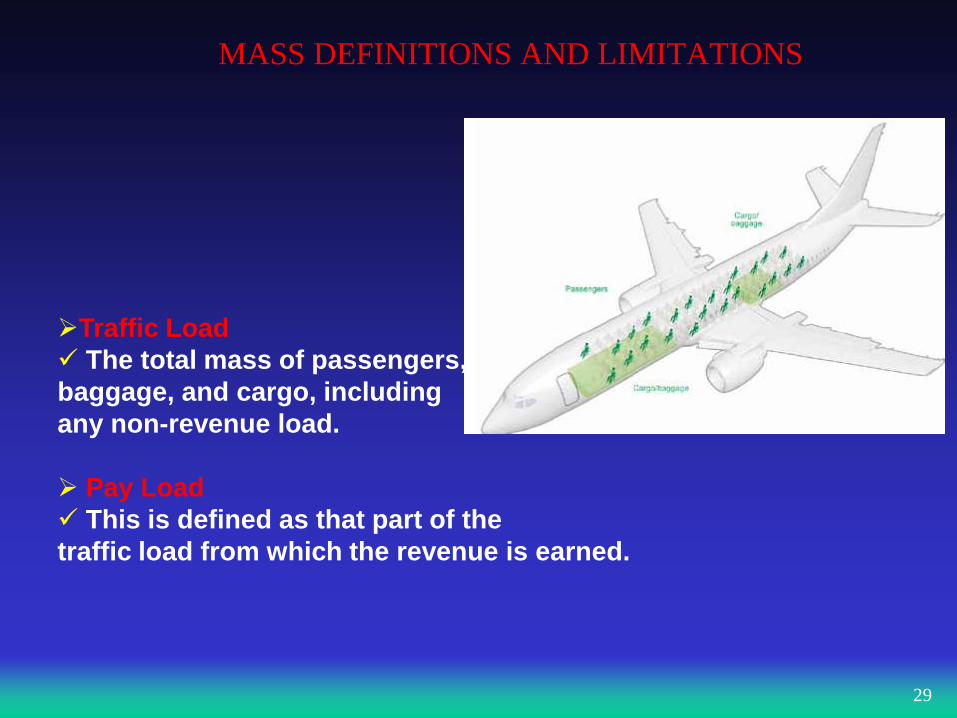
Traffic Load
The total mass of passengers,
baggage, and cargo, including
any non-revenue load.
Pay Load
This is defined as that part of the
traffic load from which the revenue is earned.
29
CHAPTER 4 MASS DEFINITIONS AND LIMITATIONS
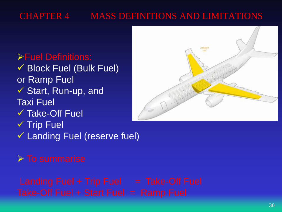
Fuel Definitions:
Block Fuel (Bulk Fuel)
or Ramp Fuel
Start, Run-up, and
Taxi Fuel
Take-Off Fuel
Trip Fuel
Landing Fuel (reserve fuel)
To summarise
Landing Fuel + Trip Fuel = Take-Off Fuel
Take-Off Fuel + Start Fuel = Ramp Fuel
30
MASS DEFINITIONS AND LIMITATIONS
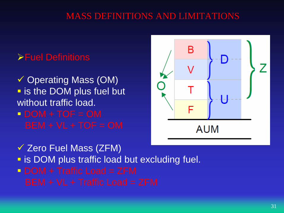
Fuel Definitions
Operating Mass (OM)
is the DOM plus fuel but
without traffic load.
DOM + TOF = OM
BEM + VL + TOF = OM
Zero Fuel Mass (ZFM)
is DOM plus traffic load but excluding fuel.
DOM + Traffic Load = ZFM
BEM + VL + Traffic Load = ZFM
31
MASS DEFINITIONS AND LIMITATIONS
STRUCTURAL LIMITATIONS: Maximum Structural Taxi Mass (MSTM)
is the structural limitation on the mass of the aeroplane at the
commencement of taxi.(Maksimum Taxi/Ramp Mass)
Maximum Structural Take-Off Mass
The maximum permissible total aeroplane mass at the start of the
take-off run.(Maximum Take-off Mass – MTOM)
32
MASS DEFINITIONS AND LIMITATIONS
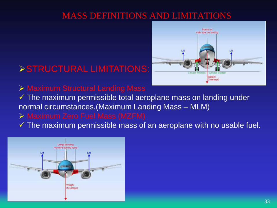
STRUCTURAL LIMITATIONS:
Maximum Structural Landing Mass
The maximum permissible total aeroplane mass on landing under
normal circumstances.(Maximum Landing Mass – MLM)
Maximum Zero Fuel Mass (MZFM)
The maximum permissible mass of an aeroplane with no usable fuel.
33
MASS DEFINITIONS AND LIMITATIONS
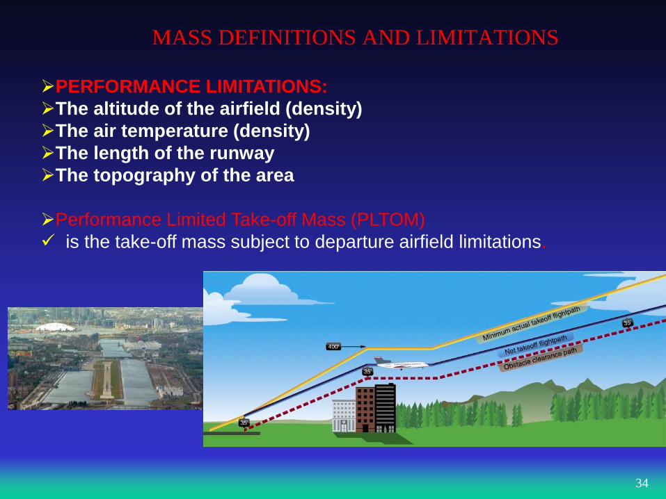
PERFORMANCE LIMITATIONS:
The altitude of the airfield (density)
The air temperature (density)
The length of the runway
The topography of the area
Performance Limited Take-off Mass (PLTOM)
is the take-off mass subject to departure airfield limitations.
34
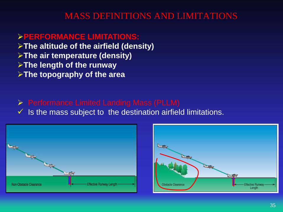
MASS DEFINITIONS AND LIMITATIONS
PERFORMANCE LIMITATIONS:
The altitude of the airfield (density)
The air temperature (density)
The length of the runway
The topography of the area
Performance Limited Landing Mass (PLLM)
Is the mass subject to the destination airfield limitations.
35
MASS DEFINITIONS AND LIMITATIONS
REGULATED LIMITATIONS:
Regulated Take-off Mass (RTOM)
Is the lowest of Performance Limited and Structurtal Limited Take-
Off Mass.( Maximum Allowable Take-Off Mass (MATOM)
Regulated Landing Mass (RLM)
Is the lowest of Performance Limited and Structural Limited Landing
Mass. (Maximum Allowable Landing Mass)(MALM)
36
MASS DEFINITIONS AND LIMITATIONS
CALCULATING THE MAXIMUM TAKE-OFF MASS
• The maximum mass at which an aeroplane can take-off is the
most restrictive(lowest) of the three limitations below:
1. The regulated take-off mass RTOM, which is the more
restrictive (lower) of the performance limited take-off mass
and the maximum structural take-off mass.
2. The regulated landing mass RLM (which is the more
restrictive of the performance limited landing mass and the
maximum structural landing mass) plus the trip fuel.
3. The Maximum Zero Fuel Mass MZFM plus the fuel at take-
off.
37
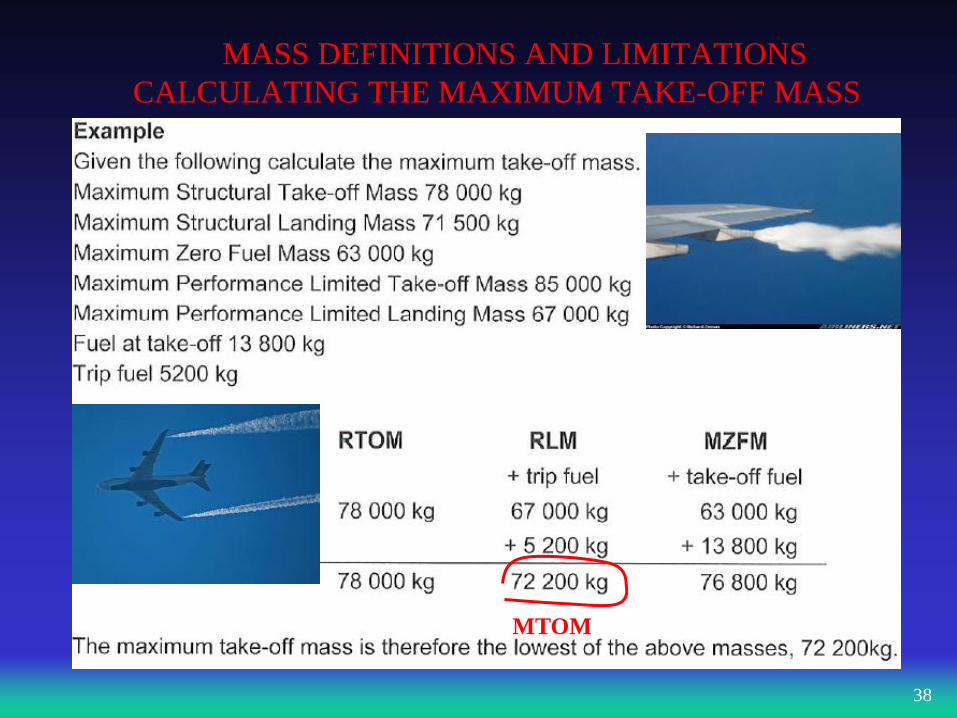
MASS DEFINITIONS AND LIMITATIONS
CALCULATING THE MAXIMUM TAKE-OFF MASS
38
MTOM
AIRCRAFT FLOOR LOADING
CARGO HANDLING
• Cargo Compartments:
• Compartments in the lower deck accomodate baggage
and cargo.
• All compartments have a maximum floor loading
(kg/m²) and maximum running load value (kg/m).
• Containerised Cargo
• Palletised Cargo
• Bulk Cargo
39
AIRCRAFT FLOOR LOADING
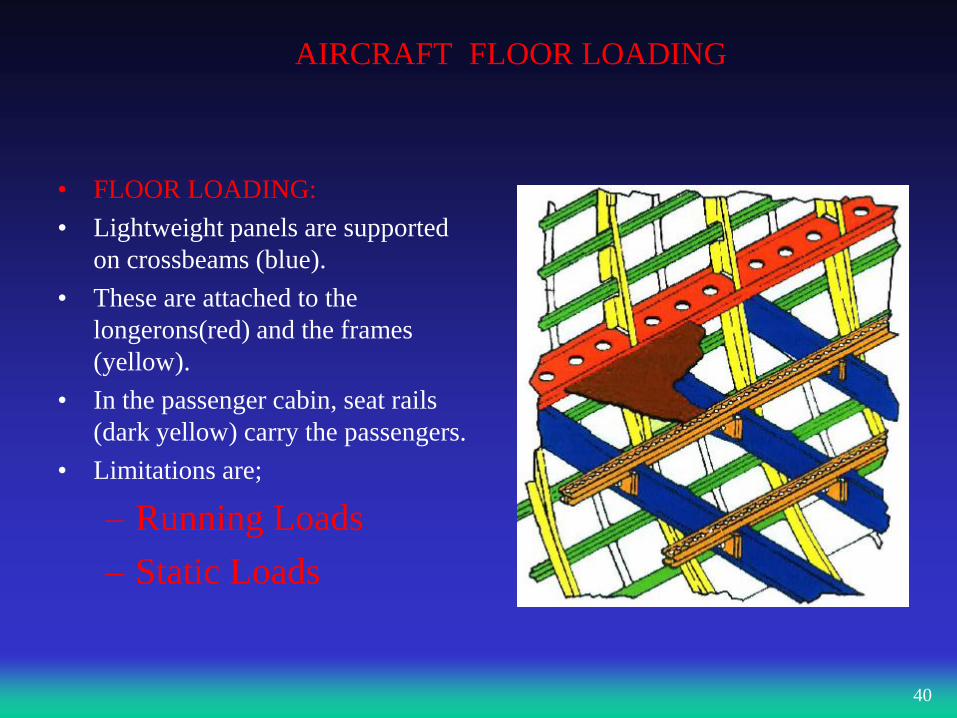
• FLOOR LOADING:
• Lightweight panels are supported
on crossbeams (blue).
• These are attached to the
longerons(red) and the frames
(yellow).
• In the passenger cabin, seat rails
(dark yellow) carry the passengers.
• Limitations are;
– Running Loads
– Static Loads
40
AIRCRAFT FLOOR LOADING
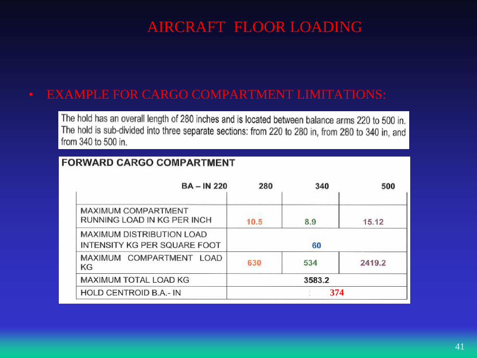
• EXAMPLE FOR CARGO COMPARTMENT LIMITATIONS:
41
374
AIRCRAFT FLOOR LOADING
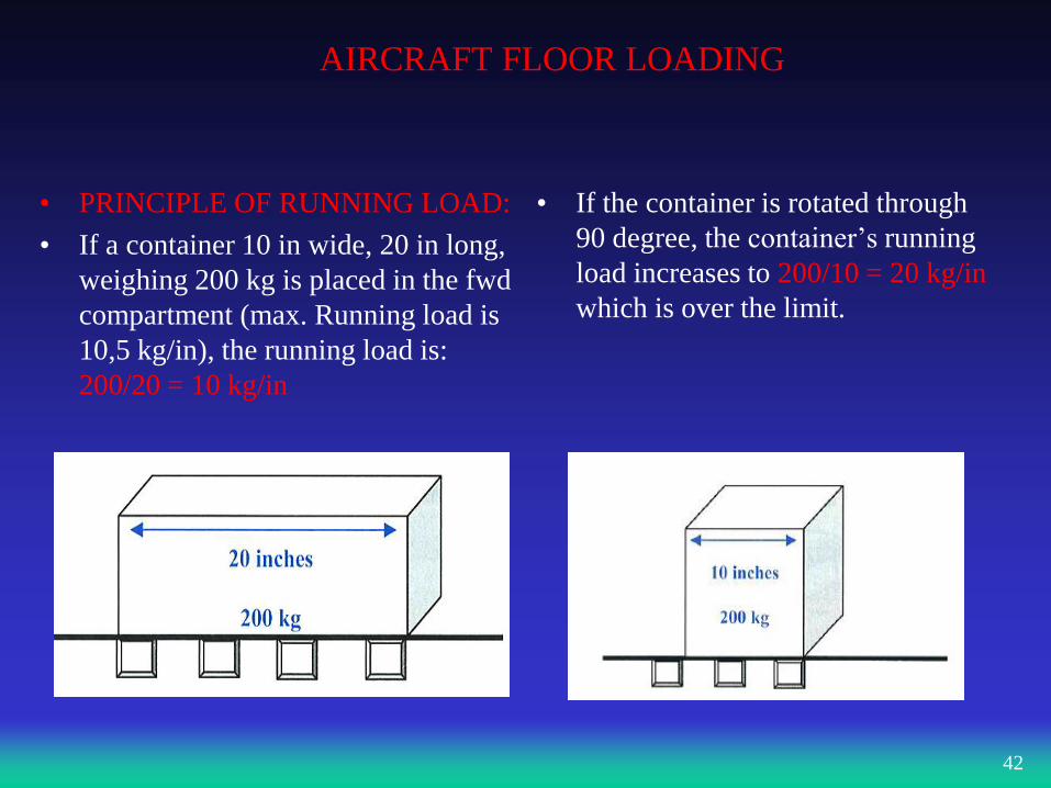
• PRINCIPLE OF RUNNING LOAD:
• If a container 10 in wide, 20 in long,
weighing 200 kg is placed in the fwd
compartment (max. Running load is
10,5 kg/in), the running load is:
200/20 = 10 kg/in
• If the container is rotated through
90 degree, the container’s running
load increases to 200/10 = 20 kg/in
which is over the limit.
42
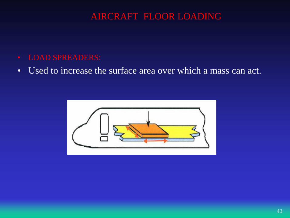
AIRCRAFT FLOOR LOADING
• LOAD SPREADERS:
• Used to increase the surface area over which a mass can act.
43
LOAD SHIFTING, LOAD ADDITION, AND LOAD
SUBSTRACTION
44
distance
distance
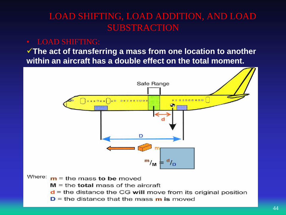
• LOAD SHIFTING:
The act of transferring a mass from one location to another
within an aircraft has a double effect on the total moment.
LOAD SHIFTING, LOAD ADDITION, AND LOAD
SUBSTRACTION
45
distance
distance
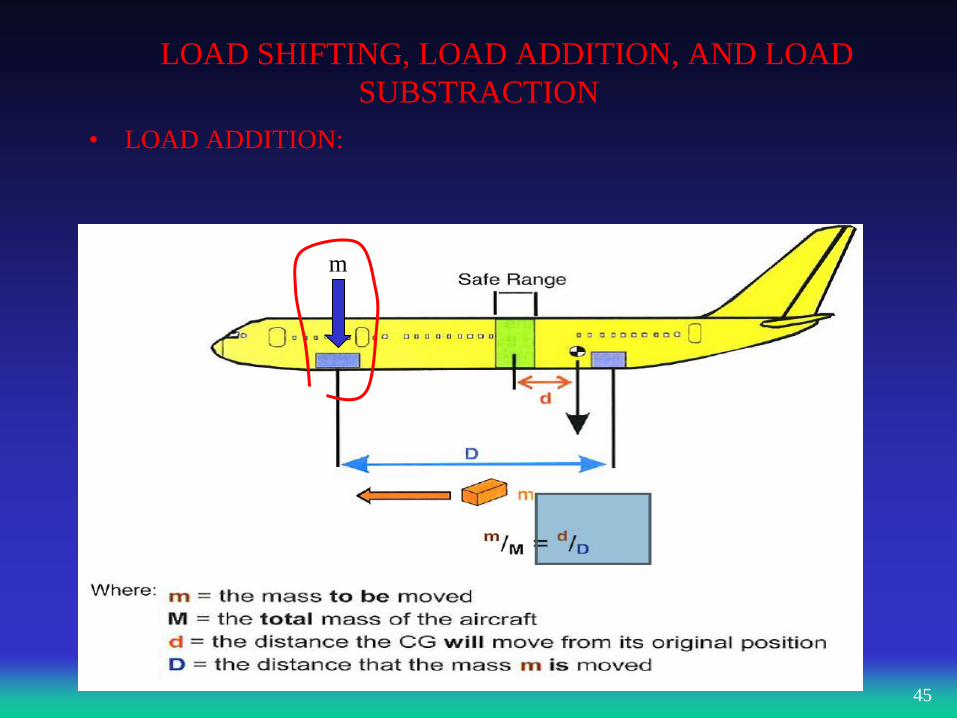
• LOAD ADDITION:
m
LOAD SHIFTING, LOAD ADDITION, AND LOAD
SUBSTRACTION
46
distance
distance
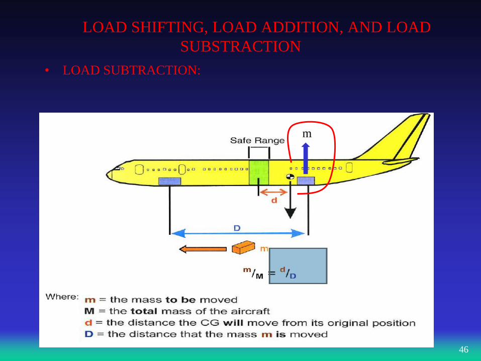
• LOAD SUBTRACTION:
m
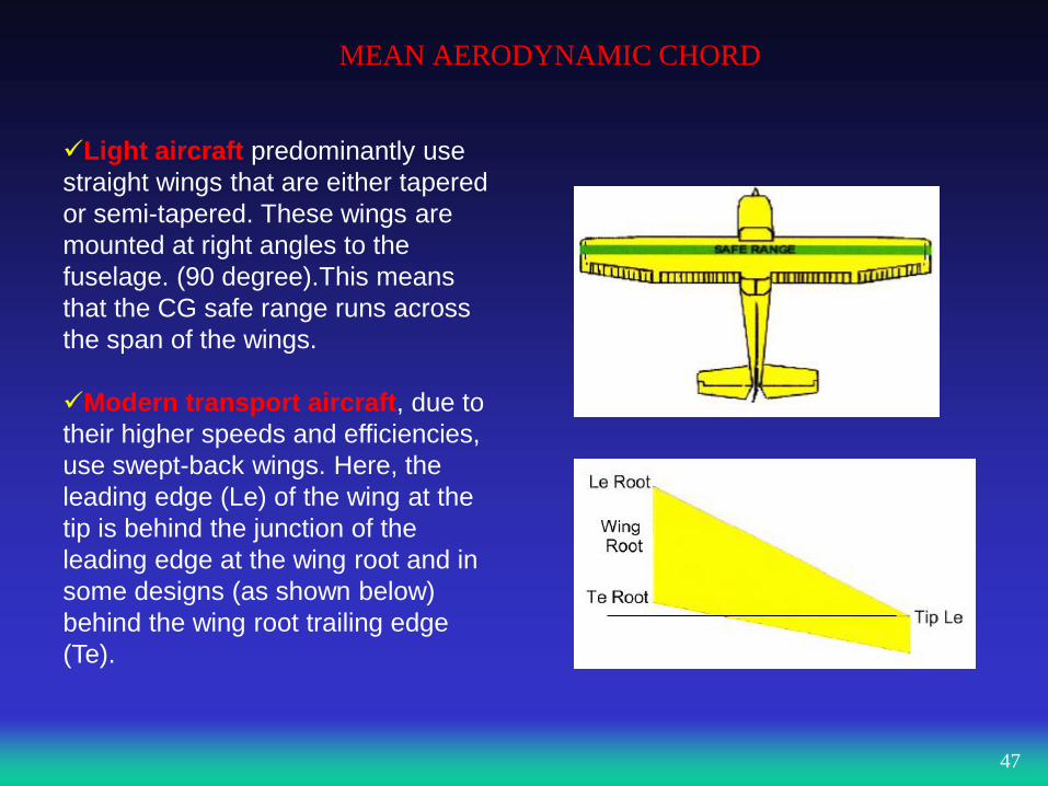
MEAN AERODYNAMIC CHORD
Light aircraft predominantly use
straight wings that are either tapered
or semi-tapered. These wings are
mounted at right angles to the
fuselage. (90 degree).This means
that the CG safe range runs across
the span of the wings.
Modern transport aircraft, due to
their higher speeds and efficiencies,
use swept-back wings. Here, the
leading edge (Le) of the wing at the
tip is behind the junction of the
leading edge at the wing root and in
some designs (as shown below)
behind the wing root trailing edge
(Te).
47
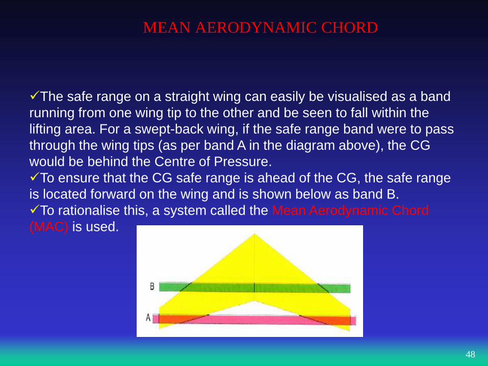
MEAN AERODYNAMIC CHORD
The safe range on a straight wing can easily be visualised as a band
running from one wing tip to the other and be seen to fall within the
lifting area. For a swept-back wing, if the safe range band were to pass
through the wing tips (as per band A in the diagram above), the CG
would be behind the Centre of Pressure.
To ensure that the CG safe range is ahead of the CG, the safe range
is located forward on the wing and is shown below as band B.
To rationalise this, a system called the Mean Aerodynamic Chord
(MAC) is used.
48
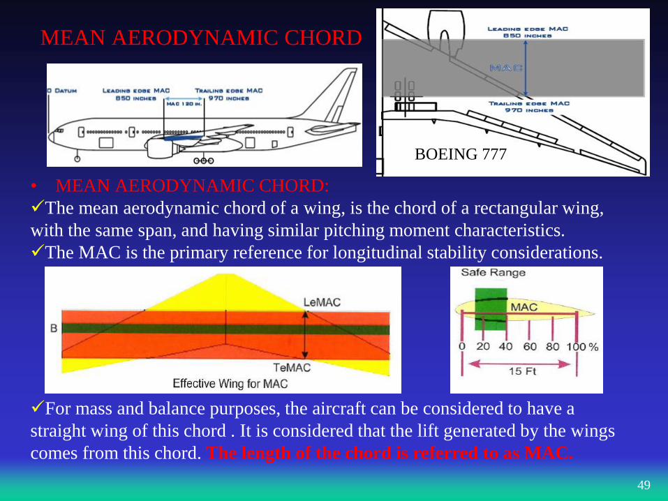
MEAN AERODYNAMIC CHORD
• MEAN AERODYNAMIC CHORD:
The mean aerodynamic chord of a wing, is the chord of a rectangular wing,
with the same span, and having similar pitching moment characteristics.
The MAC is the primary reference for longitudinal stability considerations.
For mass and balance purposes, the aircraft can be considered to have a
straight wing of this chord . It is considered that the lift generated by the wings
comes from this chord. The length of the chord is referred to as MAC.
49
BOEING 777
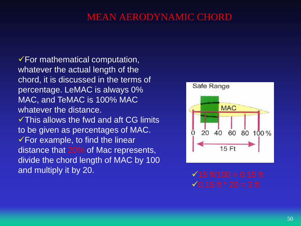
MEAN AERODYNAMIC CHORD
For mathematical computation,
whatever the actual length of the
chord, it is discussed in the terms of
percentage. LeMAC is always 0%
MAC, and TeMAC is 100% MAC
whatever the distance.
This allows the fwd and aft CG limits
to be given as percentages of MAC.
For example, to find the linear
distance that 20% of Mac represents,
divide the chord length of MAC by 100
and multiply it by 20.
50
15 ft/100 = 0.15 ft
0.15 ft * 20 = 3 ft
MEAN AERODYNAMIC CHORD
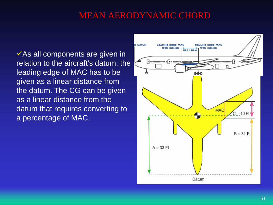
As all components are given in
relation to the aircraft's datum, the
leading edge of MAC has to be
given as a linear distance from
the datum. The CG can be given
as a linear distance from the
datum that requires converting to
a percentage of MAC.
51
MEAN AERODYNAMIC CHORD
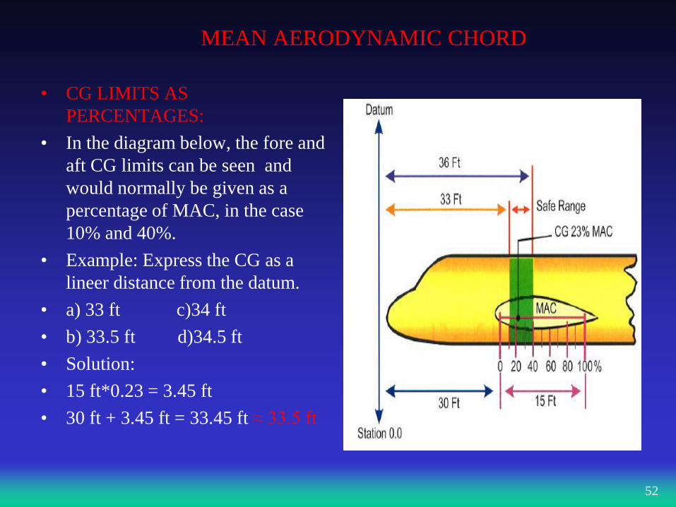
• CG LIMITS AS
PERCENTAGES:
• In the diagram below, the fore and
aft CG limits can be seen and
would normally be given as a
percentage of MAC, in the case
10% and 40%.
• Example: Express the CG as a
lineer distance from the datum.
• a) 33 ft c)34 ft
• b) 33.5 ft d)34.5 ft
• Solution:
• 15 ft*0.23 = 3.45 ft
• 30 ft + 3.45 ft = 33.45 ft ≈ 33.5 ft
52
JAR – OPS 1 REQUIREMENTS
MASS VALUES FOR CREWS:
Operators are required to account for the mass of their crew
members and baggage as part of determining the dry operating
mass. The operator can use:
The actual mass of the crewmembers and their baggage
The standard mass of 85 kg for flight crew and 75 kg
for cabin crew (regardless of gender or build) Any other standard mass acceptable to the Aviation Authority
The operator must correct the DOM and its CG position if the
crew has additional baggage.
53
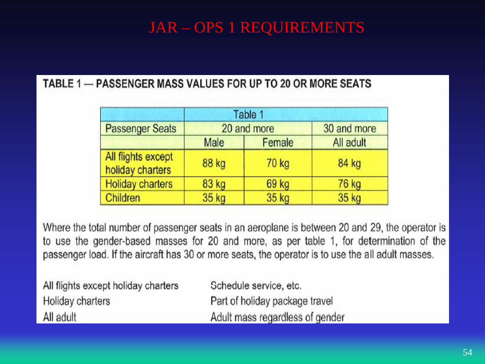
JAR – OPS 1 REQUIREMENTS
54
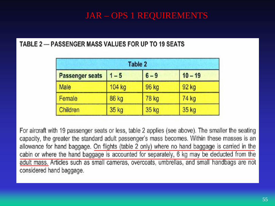
JAR – OPS 1 REQUIREMENTS
55
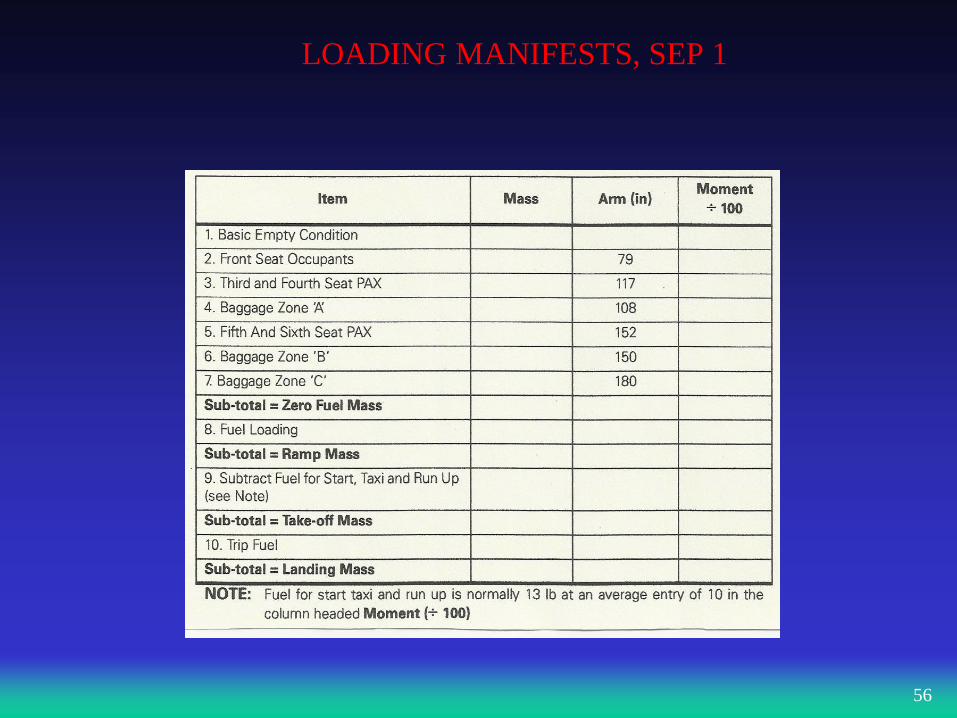
LOADING MANIFESTS, SEP 1
56
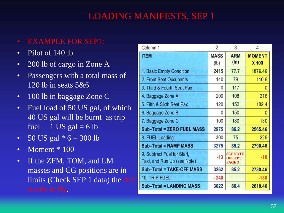
LOADING MANIFESTS, SEP 1
• EXAMPLE FOR SEP1:
• Pilot of 140 lb
• 200 lb of cargo in Zone A
• Passengers with a total mass of
120 lb in seats 5&6
• 100 lb in baggage Zone C
• Fuel load of 50 US gal, of which
40 US gal will be burnt as trip
fuel 1 US gal = 6 lb
• 50 US gal * 6 = 300 lb
• Moment * 100
• If the ZFM, TOM, and LM
masses and CG positions are in
limits (Check SEP 1 data) the A/C
is safe to fly.
57
SEE NOTE
ON SEP1
PAGE 3
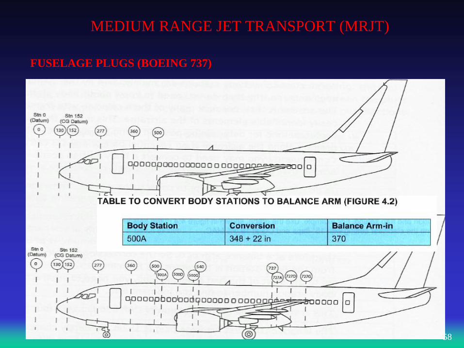
MEDIUM RANGE JET TRANSPORT (MRJT)
58
FUSELAGE PLUGS (BOEING 737)
MEDIUM RANGE JET TRANSPORT (MRJT)
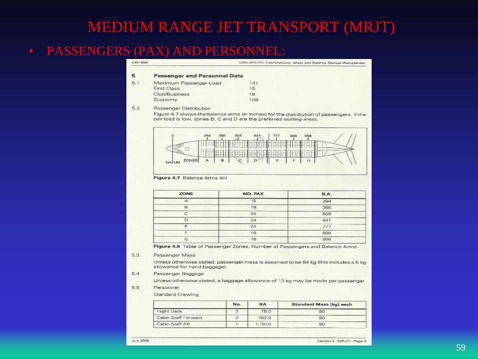
• PASSENGERS (PAX) AND PERSONNEL:
59
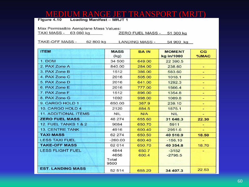
MEDIUM RANGE JET TRANSPORT (MRJT)
60
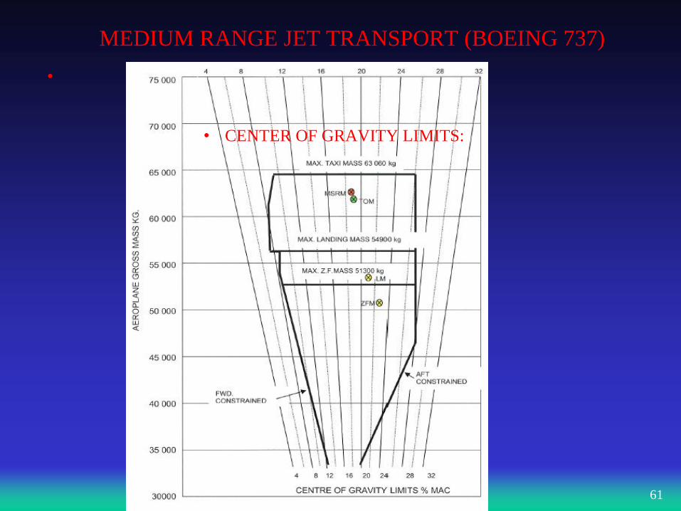
MEDIUM RANGE JET TRANSPORT (BOEING 737)
•
61
• CENTER OF GRAVITY LIMITS:
MEDIUM RANGE JET TRANSPORT (MRJT)
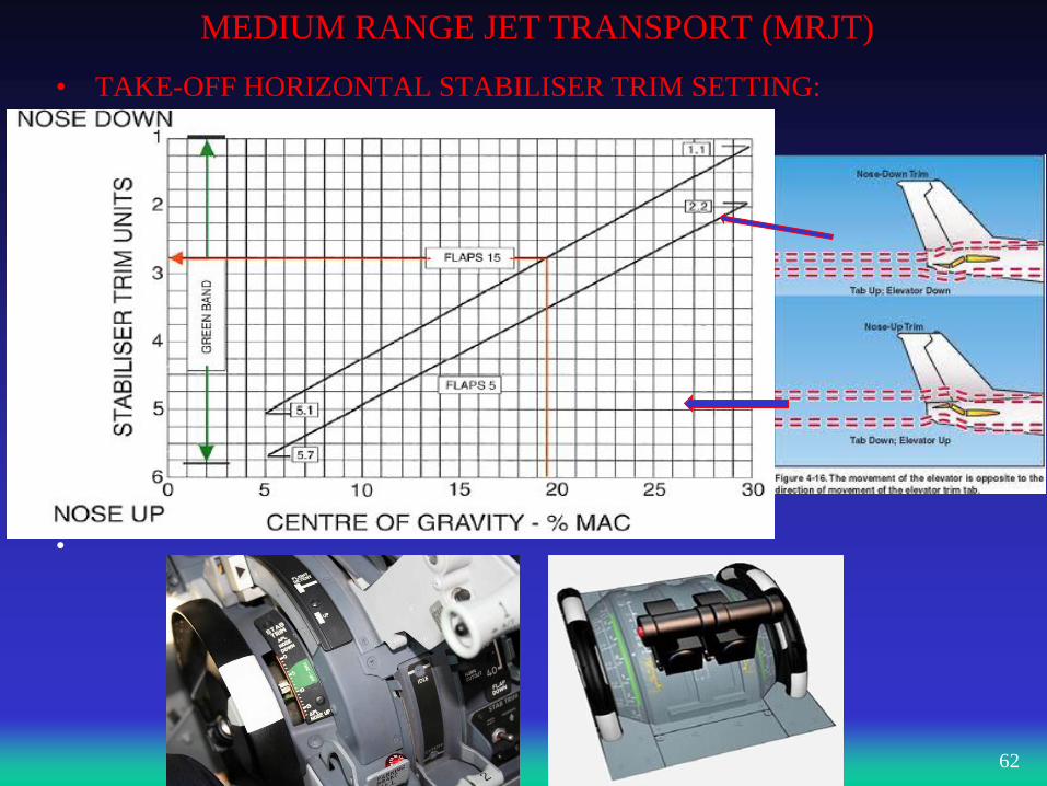
• TAKE-OFF HORIZONTAL STABILISER TRIM SETTING:
•
62
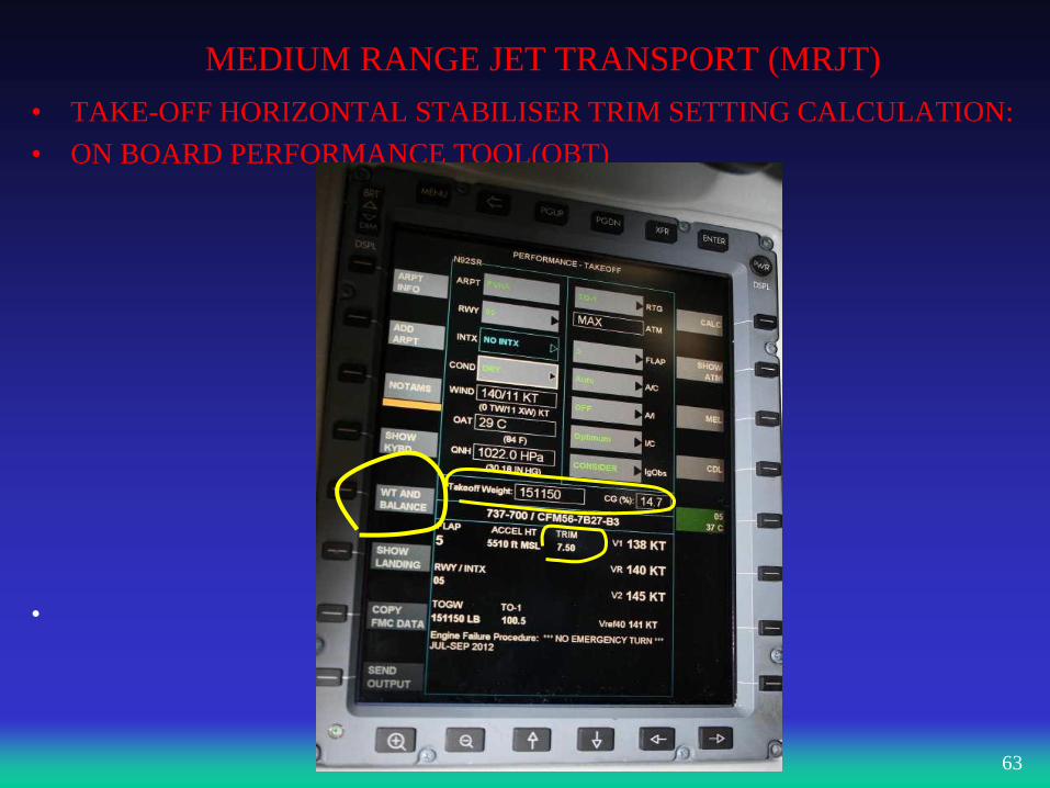
MEDIUM RANGE JET TRANSPORT (MRJT)
• TAKE-OFF HORIZONTAL STABILISER TRIM SETTING CALCULATION:
• ON BOARD PERFORMANCE TOOL(OBT)
•
63
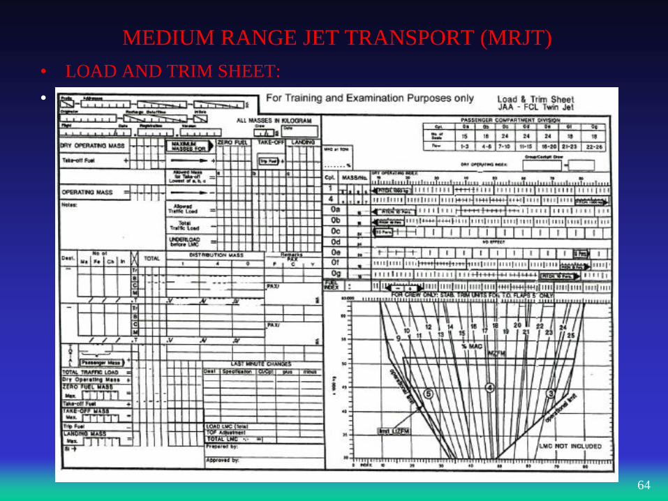
MEDIUM RANGE JET TRANSPORT (MRJT)
• LOAD AND TRIM SHEET:
•
64
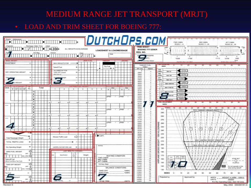
MEDIUM RANGE JET TRANSPORT (MRJT)
• LOAD AND TRIM SHEET FOR BOEING 777:
•
65
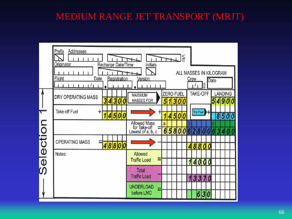
MEDIUM RANGE JET TRANSPORT (MRJT)
66
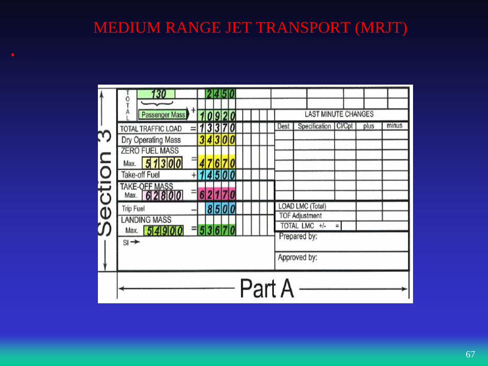
MEDIUM RANGE JET TRANSPORT (MRJT)
•
67
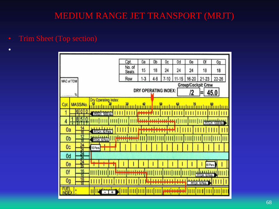
MEDIUM RANGE JET TRANSPORT (MRJT)
• Trim Sheet (Top section)
•
68
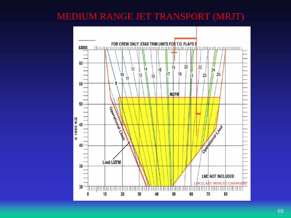
MEDIUM RANGE JET TRANSPORT (MRJT)
69
LMC(LAST MINUTE CHANGES)
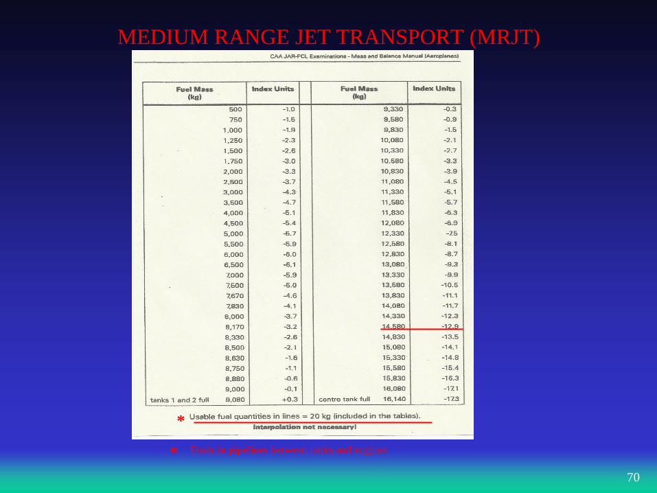
MEDIUM RANGE JET TRANSPORT (MRJT)
70
Fuels in pipelines between tanks and engines
*
*
MEDIUM RANGE JET TRANSPORT (MRJT)
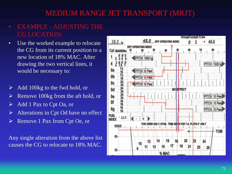
• EXAMPLE - ADJUSTING THE
CG LOCATION:
• Use the worked example to relocate
the CG from its current position to a
new location of 18% MAC. After
drawing the two vertical lines, it
would be necessary to:
Add 100kg to the fwd hold, or
Remove 100kg from the aft hold, or
Add 1 Pax to Cpt Oa, or
Alterations in Cpt Od have no effect
Remove 1 Pax from Cpt Oe, or
Any single alteration from the above list
causes the CG to relocate to 18% MAC.
71
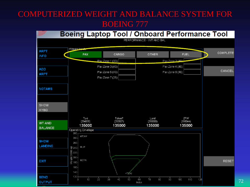
COMPUTERIZED WEIGHT AND BALANCE SYSTEM FOR
BOEING 777
72
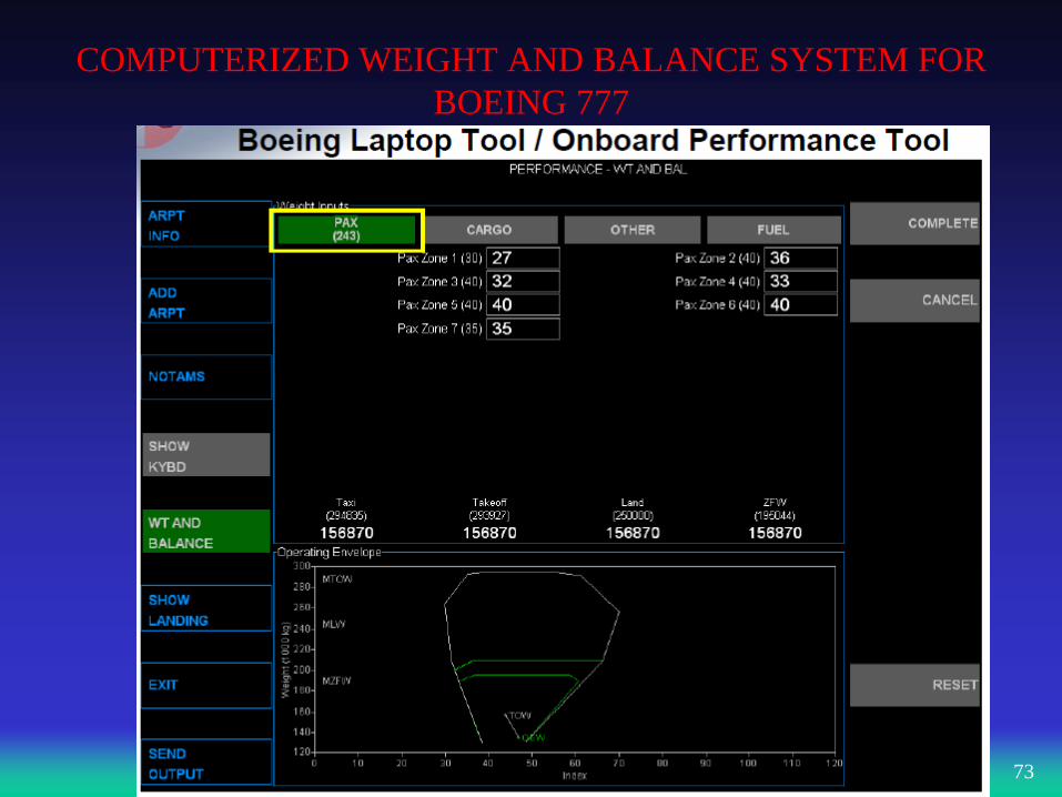
COMPUTERIZED WEIGHT AND BALANCE SYSTEM FOR
BOEING 777
73
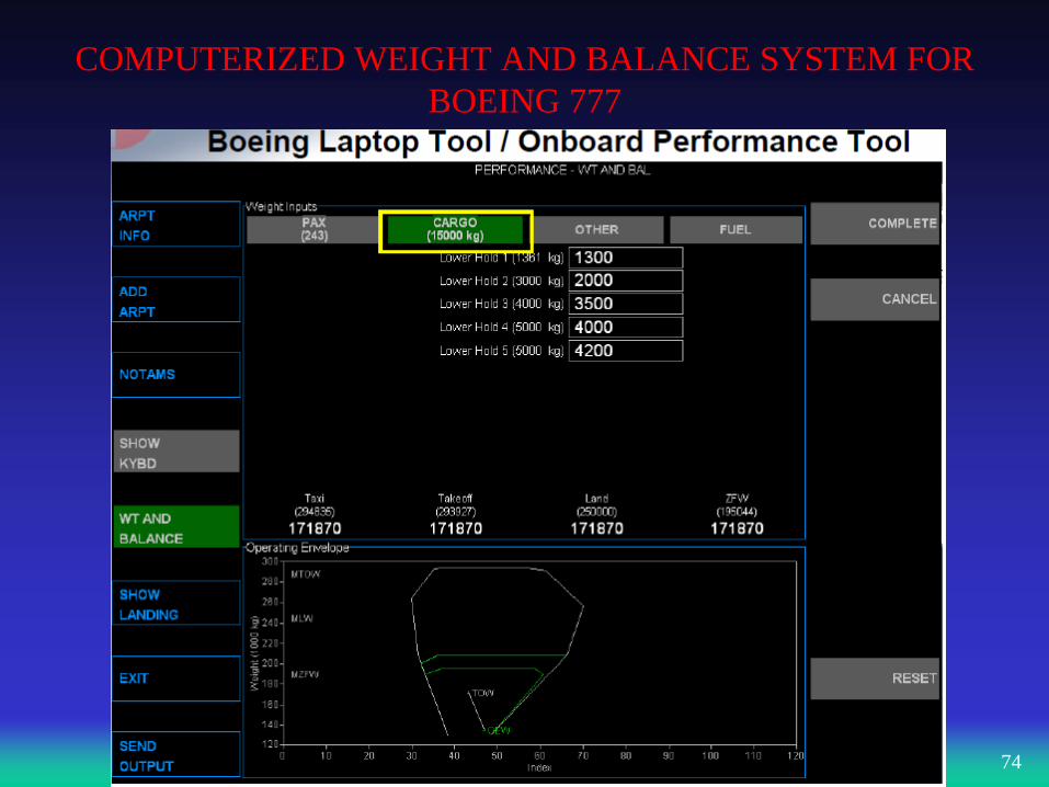
COMPUTERIZED WEIGHT AND BALANCE SYSTEM FOR
BOEING 777
74
COMPUTERIZED WEIGHT AND BALANCE SYSTEM FOR
BOEING 777
75
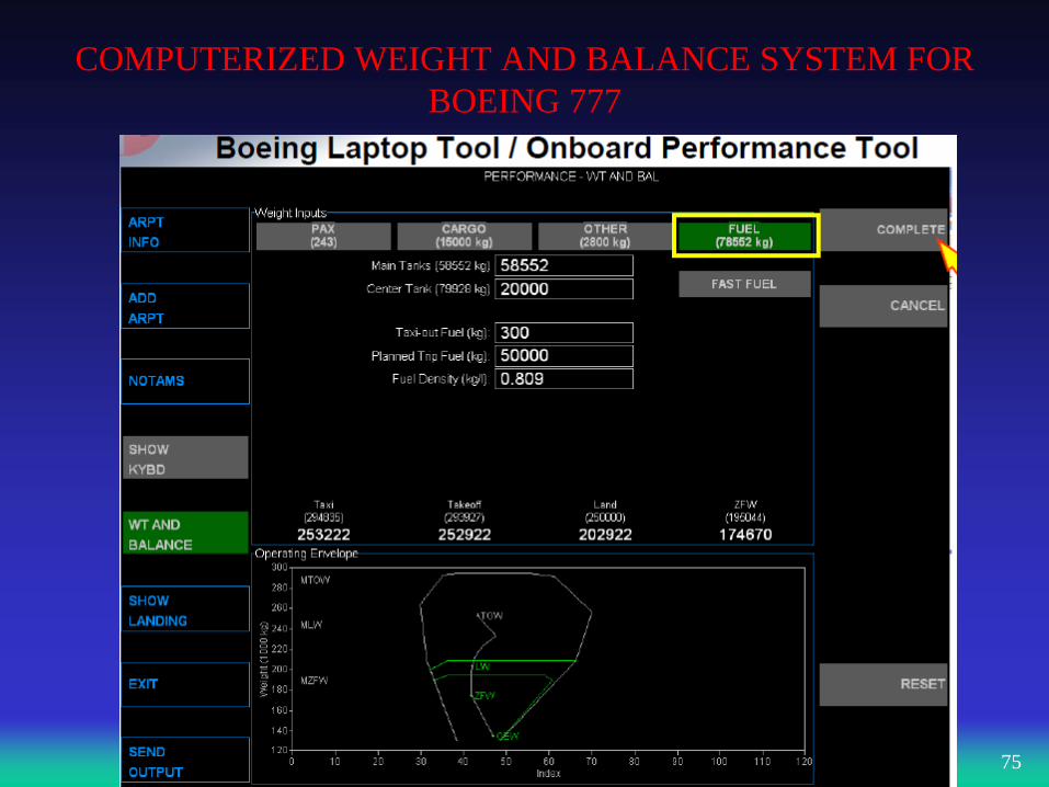
COMPUTERIZED WEIGHT AND BALANCE SYSTEM FOR
BOEING 777
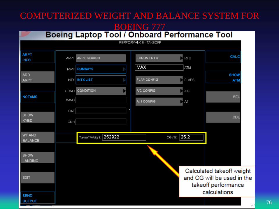
76
COMPUTERIZED WEIGHT AND BALANCE SYSTEM FOR
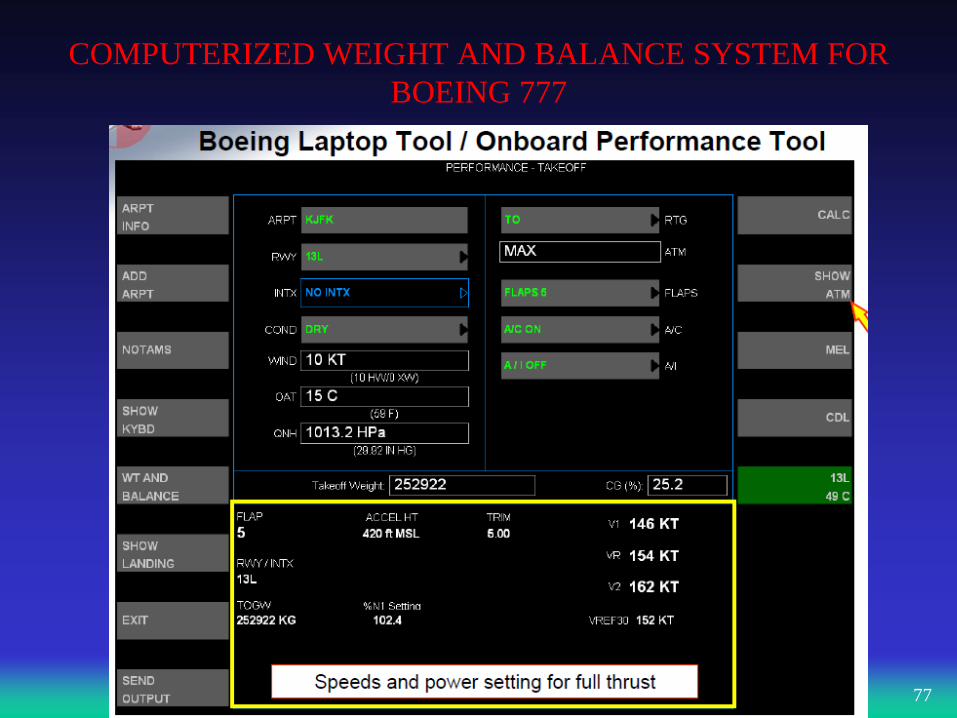
BOEING 777
77
REFERENCE
• JAA ATPL Theoretical Knowledge Manual, 031 00 MASS AND
BALANCE, Oxford Aviation Services, Published by Jeppesen GmbH,
Frankfurt, Germany
• www.padpilot.co.uk
• www.captainpilot.com
78