Embed Size (px)
Citation preview
Xlll MASS RANDOM ACCESS DATA STORAGE SUBSYSTEM
GENERAL DESCRIPTION
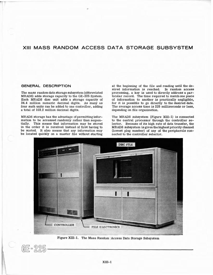
The mass random data storage subsystem (abbreviated MRADS) adds storage capacity to the GE-225 System. Each MRADS disc unit adds a storage capacity of 34.4 million numeric decimal digits. As many a s four such units can be added to one controller, adding a total of 103.2 million decimal digits.
MRADS storage has the advantage of permittinginfor- mation to be accessed randomly rather than sequen- tially. This means that information may be stored in the order it is received instead of first having to be sorted. It also means that any information may be located quickly on a master file without starting
CONTRO
at the beginning of the file and reading until the de- sired information i s reached. In random access processing, a key i s used to directly address a par- ticular record. The time required to matchone piece of information to another is practically negligible, for it i s possible to go directly to the desired data. The average access time is 225 milliseconds o r less, depending on file organization.
The MRADS subsystem (Figure XIII-1) is connected to the central processor through the controller se- lector. Because of i ts high rate of data transfer, the MRADS subsystem i s given the highest priority channel (lowest plug number) of any of the peripherals con- nected to the controller selector.
Figure XIII-1. The Mass Random /Access Data Storage Subsystem I
XIII- 1
The subsystem consists of a controller and from one to four disc units, each with its own electronics unit.
Disc Unit
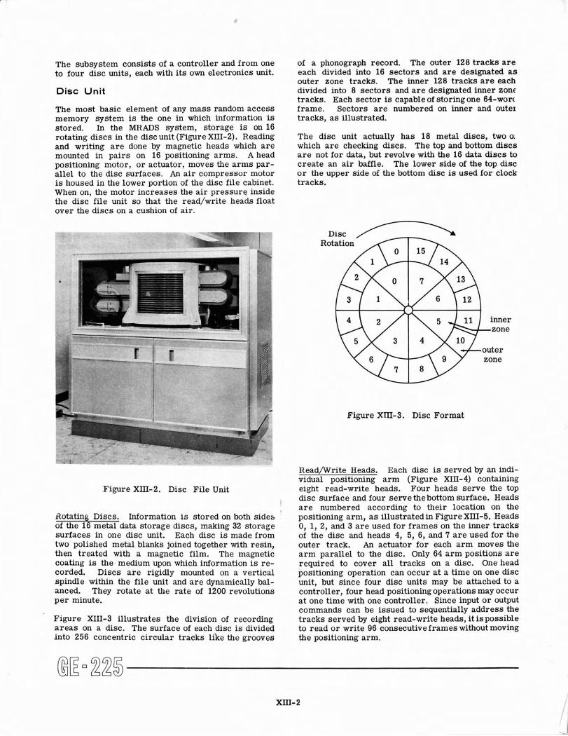
The most basic element of any mass random access memory system is the one in which information is stored. In the MRADS system, storage is on 16 rotating discs in the disc unit (Figure XIII-2). Reading and writing a r e done by magnetic heads which a r e mounted in pairs on 16 positioning arms. A head positioning motor, or actuator, moves the arms par- allel to the disc surfaces. An air compressor motor is housed in the lower portion of the disc file cabinet. When on, the motor increases the air pressure inside the disc file unit so that the read/write heads float over the discs on a cushion of air.
of a phonograph record. The outer 128 tracks a r e each divided into 16 sectors and a r e designated a s outer zone tracks. The inner 128 tracks a r e each divided into 8 sectors and a r e designated inner zonf tracks. Each sector is capable of storing one 64-won frame. Sectors a r e numbered on inner and outel tracks, a s illustrated.
The disc unit actually has 18 metal discs, two o; which a r e checking discs. The top and bottom discs a r e not for data, but revolve with the 16 data discs to create an air baffle. The lower side of the top disc o r the upper side of the bottom disc is used for clock tracks.
Figure Xm-3. Disc Format
Figure XIII-2. Disc File Unit
Rotating Discs. Information is stored on both sides of the 16 metal data storage discs, making 32 storage surfaces in one disc unit. Each disc is made from two polished metal blanks joined together with resin, then treated with a magnetic film. The magnetic coating is the medium upon which information is re- corded. Discs a r e rigidly mounted on a vertical spindle within the file unit and a r e dynamically bal- anced. They rotate a t the rate of 1200 revolutions per minute.
Figure XIII-3 illustrates the division of recording a r ea s on a disc. The surface of each disc is divided into 256 concentric circular tracks like the grooves
~ e a d / ~ r i t e Heads. Each disc is served by an indi- vidual positioning a rm (Figure XIII-4) containing eight read-write heads. Four heads serve the top
i disc surface and four servethebottom surface. Heads a r e numbered according to their location on the positioning arm, a s illustrated in Figure XIII-5. Heads 0, 1, 2, and 3 a r e used for frames on the inner tracks of the disc and heads 4, 5, 6, and 7 a r e used for the outer track. An actuator for each a rm moves the a rm parallel to the disc. Only 64 a rm positions a r e required to cover all tracks on a disc. One head positioning operation can occur a t a time on one disc unit, but since four disc units may be attached to a controller, four head positioning operations may occur a t one time with one controller. Since input o r output commands can be issued to sequentially address the tracks served by eight read-write heads, i t is possible to read o r write 96 consecutive frames without moving the positioning arm.
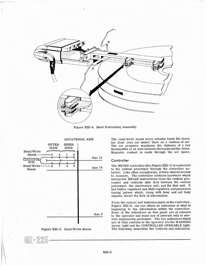
Figure XIII-4. Head Positioning Assembly
ROTATIONAL AXIS
Figure XIII-5. ~ e a d / ~ r i t e Heads
OUTER INNER ZONE ZONE 1
The read/write heads never actually touch the discs, but float over (or under) them on a cushion of air. The a i r pressure maintains the distance of a few thousandths of an inch betweenthe heads andthe discs. Magnetic contact is made through the air space. Read/Write -n
Heads - 5 4 1 0 Positioning 1 1 I v r I
Arm I I A A A'
Read/Write- 6 7 2 3 Heads
, .
Controller disc 15
disc 14
disc 0
The MRADS controller (See Figure XIII- 1) i s connected to the central processor through the controller se- lector. Like other peripherals, i t time-shares access to memory. The controller contains hardware which interprets MRADS instructions from the central pro- cessor and controls data flow between the central processor, the electronics unit, and the disc unit. It has buffer registers and shift registers, and generates timing pulses which, along with busy and not busy signals, direct the flow of information.
From the control and indicator panel on the controller, Figure XIII-6, one can obtain an indication of what i s happening to the information within the controller. Some of the indicators on this panel a r e of concern to the operator and some a r e of interest only to ser- vice engineering personnel. The two indicators which a r e of vital concern to the operator arethe WARNING alarm light and the CONTROLLVR OPERABLE light. The following describes the controls and indicators.
XIII- 3
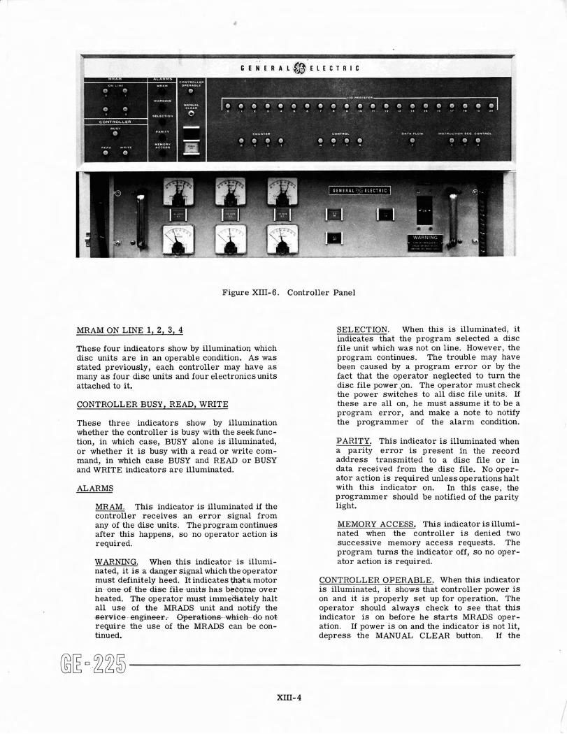
Figure XIII-6. Controller Panel
MRAM ON LINE 1, 2, 3, 4
These four indicators show by illumination which disc units a r e in an operable condition. As was stated previously, each controller may have a s many a s four disc units and four electronicsunits attached to it.
CONTROLLER BUSY, READ, WRITE
These three indicators show by illumination whether the controller is busy with the seekfunc- tion, in which case, BUSY alone is illuminated, o r whether i t is busy with a read o r write com- mand, in which case BUSY and READ o r BUSY and WRITE indicators a r e illuminated.
ALARMS
MRAM. This indicator is illuminated if the controller receives an e r r o r signal from any of the disc units. The program continues after this happens, s o no operator action is required.
WARNING. When this indicator is illumi- nated, i t is a danger signal which the operator must definitely heed. It indicates that.% motor in- one of the dfsc- f i le units has bteome over heated. The operator must i m m e h t e l y halt al l use of the MRADS unit and notify the se rv ice - engitteer, Operat;--whieh-do not require the use of the MRADS can be con- tinued.
SELECTION. When this is illuminated, it indicates that the program selected a disc file unit which was not on line. However, the program continues. The trouble may have been caused by a program e r r o r o r by the fact that the operator neglected to turn the disc file power ,on. The operator must check the power switches to all disc f i le units. If these a r e al l on, he must assume i t to be a program e r ro r , and make a note to notify the programmer of the a l a rm condition.
PARITY. This indicator is illuminated when a parity e r r o r is present in the record address transmitted to a disc file o r in data received from the disc file. No oper- a tor action is required unless operations halt with this indicator on. In this case, the programmer should be notified of the parity light.
MEMORY ACCESS. This indicator is illumi- nated when the controller is denied two successive memory access requests. The program turns the indicator off, s o no oper- a tor action is required.
CONTROLLER OPERABLE. When this indicator is illuminated, i t shows that controller power is on and i t is properly s e t up for operation. The operator should always check to s e e that this indicator is on before he s t a r t s MRADS oper- ation. If power i s on and the indicator is not lit, depress the MANUAL CLEAR button. If the
indicator does not become lit, the service engineer must be called to remedy the situation before operation can commence.
MANUAL CLEAR. This pushbutton c lears the controller of any e r ro r s , causing i t to become operable after power is turned on. The operator should depress MANUAL CLEAR after power is turned on and before MRADS operation starts. When the switch has properly cleared the con- troller of errors , the CONTROLLEROPERABLE indicator is illuminated.
POWER ON. This switch is used by the operator to turn on power in the controller unit prior to MRADS operation. The pushbutton is illuminated yellow when power is on. (See Setup P~odedure.)
POWER OFF. This switch is used by the oper- ator to turn off power in the controller unit when MRADS operation is finished.
SHIFT REGISTER. These 21 indicators show the contents of the data buffer, and a r e only of use to engineering personnel during tests.
COUNTER 8, 4, 2, 1. These fourindicators show the contents of the operating counter during read o r write operations, and a r e only of use to engineering personnel.
CONTROL W X Y R. These four indicators show the status of shift register controls and a r e only of use to engineering personnel.
DATA FLOW. This indicator is illuminatedwhen the controller requires access to memory. It is of no particular interest to the operator.
INSTRUCTION SEQ. CONTROL A B C. These three indicators show the status of instruction sequence controls, and a r e only of use to engi- neering personnel.
File Electronics Unit
This unit is connected into the subsystem such that i t receives information flowing in either direction be- tween i t s disc file unit and the controller. Each file electronics unit (see Figure XIII-1) is in a separate cabinet and has i t s own maintenance panel and control and indicator panel. The unit contains sequencing
and control hardware which goJerns the operation of the positioning a r m s and read/wHte heads in the disc file unit. It tel ls the disc fileunit when to s tar t reading o r writing, and determines the record address. In- cluded in i t s hardware a r e buffer and storage registers.
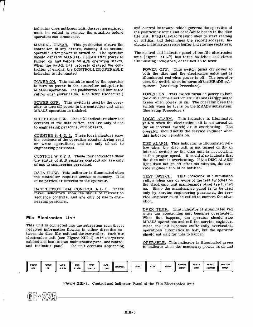
The control and indicator panel of the file electronics unit (Figure XIII-7) has three switches and eleven illuminating indicators, described a s follows:
POWER OFF. This switch turns off power to both the disc and the electronics units and is illuminated red when power is off. The operator uses the switch when he turnsoff the MRADS sub- system. (See Setup Procedure).
POWER ON. This switch turns on p o w q to both the disc and the electronics units and i4iltiypinated green when power is on. The opera* d s e s the switch when he turns on the MRADS subsystem. (See Setup Procedure.)
LOGIC ALARM. This indicator is illuminated yellow when the electronics unit is not turned on (by an internal switch) o r is overheating. The operator should notify the service engineer when this indicator remains on.
DISC ALARM. This indicator is illuminated yel- low when the disc unit is not turned on (by an internal switch) o r .the disc unit is not rotating at the proper speed. It could also indicate that the disc unit is overheating. If the DISC ALARM light does not go off after s ix minutes, the s e r - vice engineer should be notified.
TEST SWITCH. This indicator is illuminated yellow when one o r more of the test switches on the electronic unit maintenance panel a r e turned on. Since the maintenance panel is to be used only by service engineering personnel, the se r - vice engineer must be called to correct the situ- ation.
OVER TEMP. This indicator is illuminated red when the electronics unit becomes overheated. When this happens, the operator should stop MRADS operations and call the service engineer. When the unit becomes sufficiently overheated, operations automatically halt, but the operator should not wait for this to happen.
OPERABLE. This indicator is illuminated green to indicate when the necessary power is on and
Figure XIII-7. Control and Indicator Panel of the File Electronics Unit
@ E m 2 2 5 XIII- 5
OPERABLE
- - - .. -
SELECT ALERT READY
circuits a r e clear and ready for operation with INSTRUCTIONS and MRADS the MRADS controller. OPERATION
SELECT. This indicator i s illuminated white to indicate when the electronics unit has been se- lected to receive data.
ALERT. This indicator is illuminated white when the electronics unit i s alerted to get ready to receive data.
READY. This indicator i s illuminated white when the electronics unit is ready to receive datafrom either the controller o r the disc unit.
The following four indicators a r e illuminated red to indicate various e r r o r conditions. Each causes MRADS operations to halt. All of these e r r o r s re- qui re the same operator action.
ADDRESS ERROR. This i s both a switch and an indicator. It glows red when an e r r o r has occurred during the address mode of a MRADS operation. When depressed, it rese ts the c i r - cuitry after any kind of an address e r ro r .
PARITY EVEN. This indicator glows red when a parity e r r o r has occurred.
INVALID ADDRESS. This indicator glows red when the program, due to an e r ro r , calls for a nonexistent address.
POSITION ERROR. This indicator glows red when the positioning a r m of the disc unit is not positioned correctly for the address called for by the program.
When any one of the above four indicators comes on and operations halt, the operator
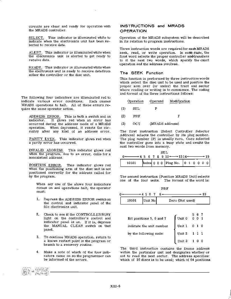
Operation of the MRADS subsystem will be described in i t s relation to program instructions.
Three instruction words a r e requiredfor eaoIsMRADS seek, read, o r write operation. In eaoh. tase , the f i r s t word selects the proper controller a d t r a n s f e r s to i t the next two words, which specify the exact operation and the address involved.
The SEEK Function
This function is performed by three instruction words which select the disc unit to be used and position the proper a r m over (or under) the t rac t and sector where reading o r writing i s to commence. The coding and format of the three instructions follows:
Operation Operand Modification
(1) SEL P
(2) PRF F
(3) OCT (MRADS address)
The f i r s t instruction (Select Controller Selector Address) selects the controller by i t s plug number. The plug number (P) i s usually zero. Once selected the controller goes into a busy state and awaits the next two words f rom memory.
SE L 0-4 5 6 7 8 9 10-1314- *I9
The second instruction (Position MRADS Unit) se lec ts one of the four units. The format of the word is:
PRF
0 1 0 0 0 0 0 0 0 PlugNo.
2. Check to s e e if the CONTROLLER BUSY light on the controller's control and indicator panel i s on. If i t i s , depress the MANUAL CLEAR switch on that panel.
must: 0- -4 5 6 7 8- - 19
3. TO continue MRADS operation, return to a known res t a r t point in the program o r branch to a recovery routine.
1. Depress the ADDRESS ERROR switchon
4. Make a note of which of the four indi- ca tors came on s o the programmer can be informed of the e r ro r s .
f 5 6 7
Bit positions 5, 6 and 7 Unit 0 0 0 1
the control and indicator panel of the file electronics unit.
10101
indicate the unit number I Unit O by the following code:
UnitNo
I Unit 2 1 1 1
Unit 3 1 0 0
Zero (Not used)
The third instruction contains the f r ame address within the particular unit and designates whether o r not to read the next sector. The address specifies: which of 16 discs is to be used; which of 64 positions
XIII- 6
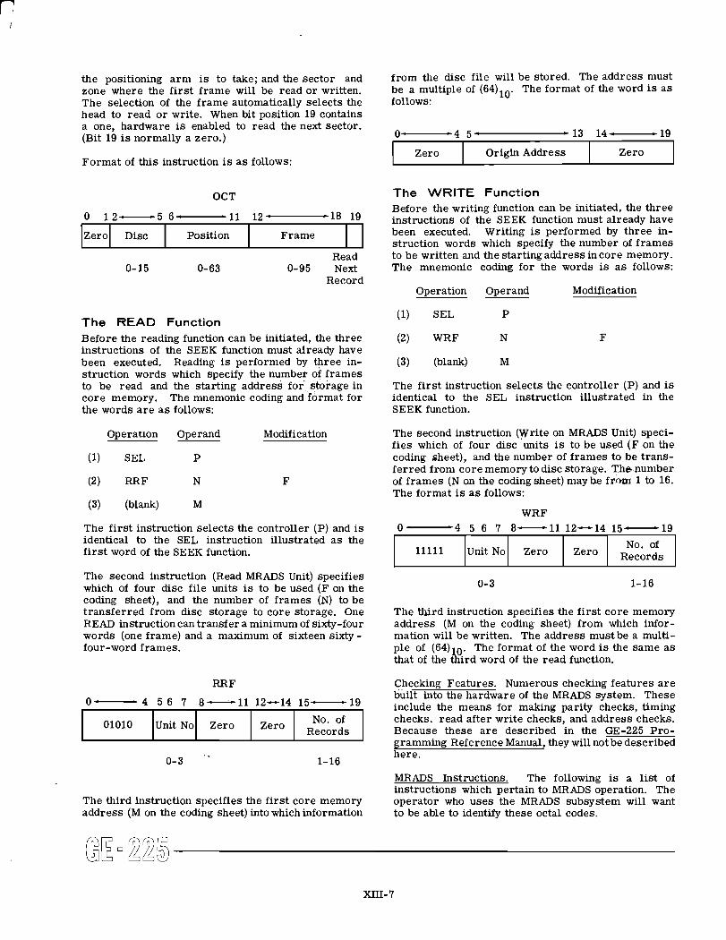
the positioning a r m is to take; and the sector and zone where the f i r s t f rame will be read o r written. The selection of the f rame automatically selects the head to read o r write. When bit position 19 contains a one, hardware is enabled to read the next sector. (Bit 19 is normally a zero.)
Format of this instruction is a s follows:
OCT
Read 0- 15 0-63 0-95 Next
Record
Zero
The READ Function Before the reading function can be initiated, the three instructions of the SEEK function must already have been executed. Reading is performed by F r e e in- struction words which specify the number of f rames to be read and the starting address for storage in core memory. The mnemonic coding and format for the words a r e a s follows:
Operation Operand Modification
Disc
(1) SEL P
(2) RRF N F
Position
The f i rs t instruction selects the controller (P) and is identical to the SEL instruction illustrated a s the f i r s t word of the SEEK function.
Frame
f rom the disc file will be stored. The address must be a multiple of (64)10. The format of the word is a s follows:
. - ... . . . ,.
The WRITE Function Before the writing function can be initiated, the three instructions of the SEEK function must already have been executed. Writing is performed by three in- struction words which specify the number of f r ames to be written and the starting address in core memory. The mnemonic coding for the words is a s follows:
U4 '4 5' - 1 3 14- - 1Y
Operation Operand Modification
(1) SEL P
Zero Zero
(2) WRF N F
Origin Address
The f i r s t instruction selects the controller (P) and is identical to the SEL instruction illustrated in the SEEK function.
The second instruction (Write on MRADS Unit) speci- f ies which of four disc units is to be used ( F on the coding sheet), and the number of f r ames to be trans- fer red from core memory to disc storage. T h e number of f r ames (N on the coding sheet) may he from 1 to 16. The format is a s follows:
WRF
No. of I 11111 lunit NO^ Zero I Zero I Records I The second instruction (Read MRADS Unit) specifies which of four disc file units is to be used ( F on the 0-3 1- 16
coding sheet), and the number of f rames (N) to be transferred from disc storage to core storage. One The third instruction specifies the f i rs t core memory READ instruction can transfer a minimum of sixty-four address (M on the coding sheet) from which infor- words (one frame) and a maximum of sixteen sixty - mation will be written. The address must be a multi- four-word frames. ple of (64)10. The format of the word is the same a s
that of the third word of the read function.
RRF Checking Features. Numerous checking features a r e built into the hardware of the MRADS system. These
O- 8-11 12-14 l5-lg include the means for making parity checks, timing
01010
gramming Reference Manual, they will not be described
0-3 "
here. 1-16
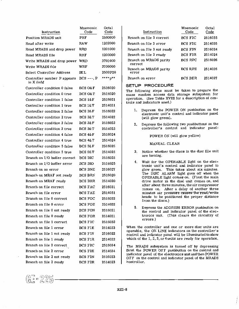
MRADS Instructions. The following is a l i s t of instructions which pertain to MRADS operation. The
The third instruction specifies the f i r s t core memory operator who uses the MRADS subsystem will want address (M on the coding sheet) into which information to be able to identify these octal codes.
checks, read after write checks, and address checks. Because these a r e described in the GE-225 Pro- Unit No Zero Zero No. of
Records
Mnemonic Octal Instruction Code Code -
Position MRADS unit PRF 2500000
Mnemonic Octal Instruction Code Code
Branch on file 3 correct BCS F3C 2516035
Read after write RAW 1202000
Read MRADS and drop power RRD 1201000
Branch on file 3 e r r o r BCS F3E 2514035
Branch on file 3 not ready BCS F3N 2516024
Read MRADS file RRF 1200000
Write MRADS and drop power WRD 3701000
Controller number P appears BCS ---, P ****p** 1 Branch on e r r o r BCS BER 2514027
Branch on file 3 ready BCS F3R 2514024
Branch on MRADS parity BCS RPC 2516026 - -
Write MRADS file WRF 3700000
Select Controller Address SE L 2500P20
correct Branch on MRADS parity BCS RPE 2514026
e r r o r
- A
in X field
Controller condition 0 false BCS O&F 2516020
Controller condition 0 t rue BCS O&T 2514020
SETUP PROCEDURE The following steps must be taken to prepare the mass random access data storage subsystem for
Controller condition 1 false BCS l & F 2516021
Controller condition 1 t rue BCS l & T 2514021
Controller condition 3 false BCS 3&F 2516023
Controller condition 3 t rue BCS 3&T 2514023
operation. (See Table XVIII for a description of con- t ro ls and indicators used.)
Controller condition 2 false BCS 2&F 2516022
Controller condition 2 t rue BCS 2&T 2514022
Controller condition 4 false
Controller condition 4 t rue
Controller condition 5 false
Controller condition 5 t rue
Branch on I/O buffer correct
Branch on 1/0 buffer e r r o r
Branch on no e r r o r
Branch on MRAF not ready
Branch on MRAF ready
Branch on file correct
Branch on file e r r o r
Branch on file 0 correct
Branch on file 0 e r r o r
Branch on file 0 not ready
Branch on file 0 ready
Branch on file 1 correct
1. Depress the POWER ON pushbutton on the electronic unit's control and indicator panel (will glow green).
BCS 4&F
BCS 4&T
BCS 5&F
BCS 5&T
BCS BIC
BCS BIO
BCS BNE
BCS BRN
BCS BRR
BCS FAC
BCS FAE
BCS FOC
BCS FOE
BCS FON
BCS FOR
BCS F1C
2. Depress the following two pushbuttons on the controller's control and indicator panel:
POWER ON (will glow yellow)
MANUAL CLEAR
3. Notice whether the discs in the disc file unit a r e turning.
4. Wait for the OPERABLE light on the elec- tronic unit's control and indicator panel to glow green. This takes about s ix minutes. The DISC ALARM light goes off when the OPERABLE light comes on. (F i r s t the main drive motor in the disc unit comes on, and af ter about three minutes, the a i r compressor comes on. After a delay of another three minutes a i r p r e s s m e cmesththa~-ead/fwmIte heads to be positioned the proper distance from the discs.)
5. Depress the ADDRESS ERROR pushbutton on the control and indicator panel of the elec- tronics unit. (This c lears the circuitry of er rors . )
Branch on file 1 ready BCS 2514022 1 which of the 1, 2,3, o;4units a r e ready for operation.
Branch on file 1 e r r o r BCS FIE 2514033
Branch on file 1 not ready BCS FIN 2516022
Branch on file 2 correct . . BCS F2C 2516034 1 The MRADS subsystem is turned off by depressing
When the controller and one o r more disc units a r e operable, the ON LINE indicators on the controller 's control and indicator panel will be illuminated to show
Branch on file 2 ready BCS F2R 2514023 1 hontroller.
Branch on file 2 e r r o r BCS F2E 2514034
Branch on file 2 not ready BCS F2N 2516023
f i r s t the POWER OFF pushbuttpn on the control and indicator panel of the electronics unit and then POWER O F F on the control and indicator panel of the MRADS
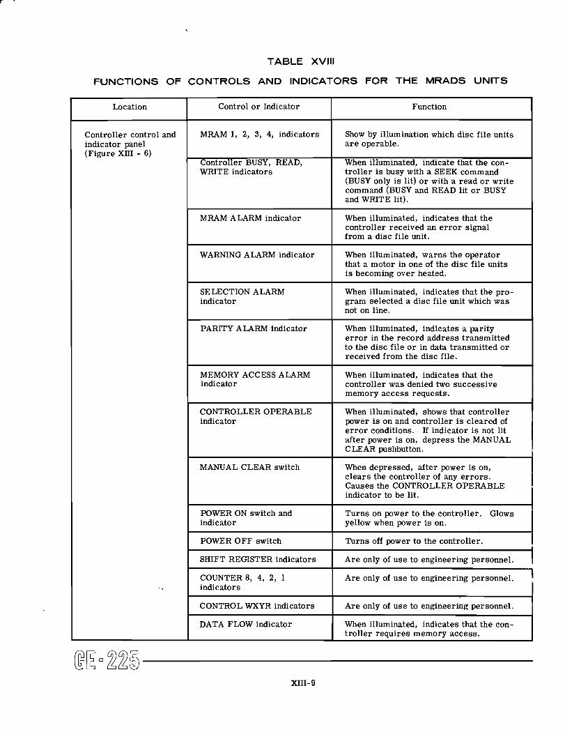
TABLE XVlll
FUNCTIONS OF CONTROLS AND INDICATORS FOR THE MRADS UNITS
EE-225 XIII- 9
Function
Show by illumination which disc file units a r e operable.
When illuminated, indicate that the con- troller i s busy with a SEEK command (BUSY only i s lit) o r with a read o r write command (BUSY and READ lit o r BUSY and WRITE lit).
When illuminated, indicates that the controller received an e r r o r signal from a disc file unit.
When illuminated, warns the operator that a motor in one of the disc file units i s becoming over heated.
When illuminated, indicates that the pro- gram selected a disc file unit which was not on line.
When illuminated, indicates a parity e r r o r in the record address transmitted to the disc file o r in data transmitted o r received from the disc file.
When illuminated, indicates that the controller was denied two successive memory access requests.
When illuminated, shows that controller power i s on and controller i s cleared of e r r o r conditions. If indicator i s not lit after power i s on, depress the MANUAL CLEAR pushbutton.
When depressed, after power i s on, c lears the controller of any e r ro r s . Causes the CONTROLLER OPERABLE indicator to be lit.
Turns on power to the controller. Glows yellow when power i s on.
Turns off power to the controller.
Are only of use to engineering personnel.
Are only of use to engineering personnel.
Are only of use to engineering personnel.
When illuminated, indicates that the con- troller requires memory access.
Location
Controller control and indicator panel (Figure XI11 - 6)
Control o r Indicator
MRAM 1, 2, 3, 4, indicators
Controller BUSY, READ, WRITE indicators
MRAM ALARM indicator
WARNING ALARM indicator
SELECTION ALARM indicator
PARITY ALARM indicator
MEMORY ACCESS ALARM indicator
CONTROLLEROPERABLE indicator
MANUAL CLEAR switch
POWER ON switch and indicator
POWER OFF switch
SHIFT REGISTER indicators
COUNTER 8, 4, 2, 1 indicators
CONTROL WXYR indicators
DATA FLOW indicator
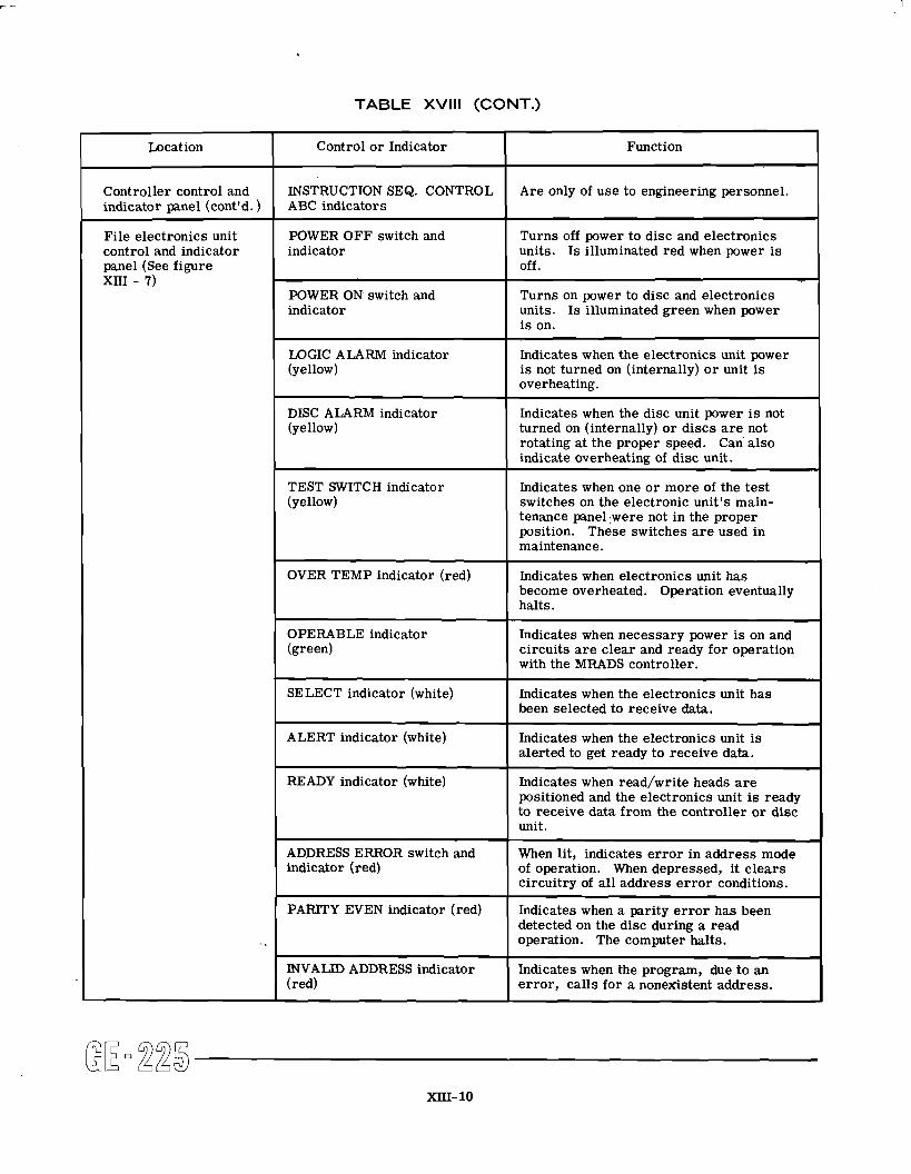
TABLE XVlll (CONT.)
Function
Are only of use to engineering personnel.
Turns off power to disc and electronics units. Is illuminated red when power is off.
Turns on power to disc and electronics units. I s illuminated green when power i s on.
Indicates when the electronics unit power i s not turned on (internally) o r unit i s overheating.
Indicates when the disc unit power i s not turned on (internally) o r discs a r e not rotating at the proper speed. Can also indicate overheating of disc unit.
Indicates when one o r more of the test switches on the electronic unit's main- tenance panel ,were not in the proper position. These switches a r e used in maintenance.
Indicates when electronics unit has become overheated. Operation eventually halts.
Indicates when necessary power i s on and circuits a r e clear and ready for operation with the MRADS controller.
Indicates when the electronics unit has been selected to receive data.
Indicates when the electronics unit i s alerted to get ready to receive data.
Indicates when read/write heads a r e positioned and the electronics unit is ready to receive data from the controller o r disc unit.
When lit, indicates e r r o r in address mode of operation. When depressed, it clears circuitry of all address e r r o r conditions.
Indicates when a parity e r r o r has been detected on the disc during a read operation. The computer halts.
Indicates when the program, due to an e r ror , calls for a nonexistent address.
Location
Controller control and indicator panel (cont'd. )
File electronics unit control and indicator panel (See figure xni - 7)
Control o r Indicator
INSTRUCTION SEQ. CONTROL ABC indicators
POWER OFF switch and indicator
POWER ON switch and indicator
LOGIC ALARM indicator (yellow)
DISC ALARM indicator (yellow)
TEST SWITCH indicator (yellow)
OVER TEMP indicator (red)
OPERABLE indicator (green)
SELECT indicator (white)
ALERT indicator (white)
READY indicator (white)
ADDRESS ERROR switch and indicator (red)
PARITY EVEN indicator (red)
INVALID ADDRESS indicator (red)
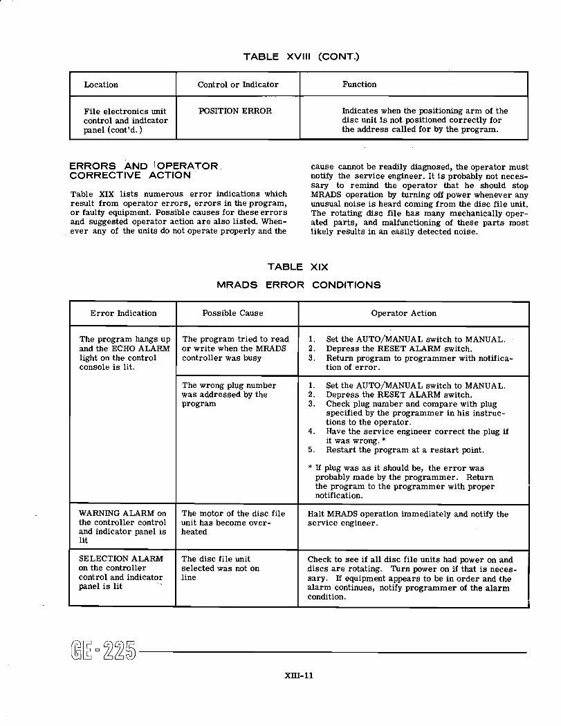
TABLE XVlll (CONT.)
ERRORS AND /OPERATOR cause cannot be readily diagnosed, the operator must CORRECTIVE ACTION notify the service engineer. It is probably not neces-
sary to remind the operator that he should stop Table XIX lists numerous error indications which MRADS operation by turning off power whenever any result from operator errors, errors in the program, unusual noise i s heard coming from the disc file unit. o r faulty equipment. Possible causes for these errors The rotating disc file has many mechanically oper- and suggested operator action a r e also listed. When- ated parts, and malfunctioning of these parts most ever any of the units do not operate properly and the likely results in an easily detected noise.
TABLE XIX
Function
Indicates when the positioning arm of the disc unit is not positioned correctly for the address called for by the program.
Location
File electronics unit control and indicator panel (cont'd. )
MRADS ERROR CONDITIONS
Control or Indicator
POSITION ERROR
Error Indication
The program hangs up and the ECHO ALARM light on the control console is lit.
WARNING ALARM on the controller control and indicator panel is lit
SELECTION ALARM on the controller control and indicator panel is lit
Possible Cause
The program tried to read or write when the MRADS controller was busy
The wrong plug number was addressed by the program
The motor of the disc file unit has become over- heated
The disc file unit selected was not on line
Operator Action
1. Set the AUTO/MANUAL switch to MANUAL. 2. Depress the RESET ALARM switch. 3. Return program to programmer with notifica-
tion of error.
1. Set the AUTO/MANUAL switch to MANUAL. 2. Depress the RESET ALARM switch. 3. Check plug number and compare with plug
specified by the programmer in his instruc- tions to the operator.
4. Have the service engineer correct the plug if it was wrong. *
5. Restart the program at a restart point.
* If plug was a s it should be, the e r ror was probably made by the programmer. Return the program to the programmer with proper notification.
Halt MRADS operation immediately and notify the service engineer.
Check to see if all disc file units had power on and discs a re rotating. Turn power on if that is neces- sary. If equipment appears to be in order and the alarm continues, notify programmer of the alarm condition.
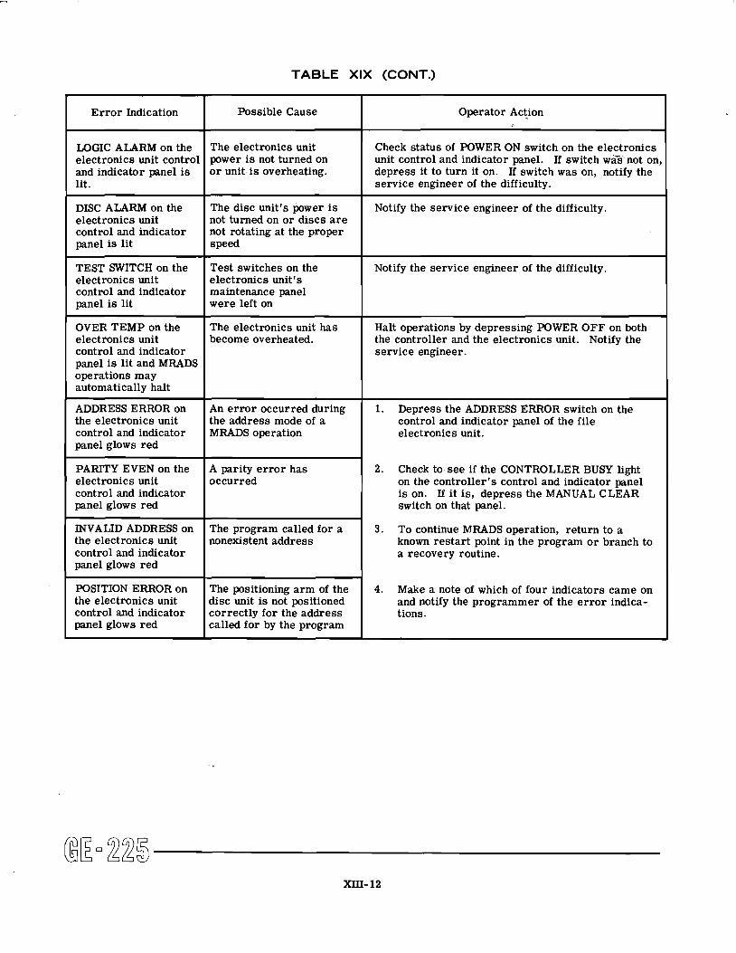
TABLE XIX (CONT.)
@E-225 XIII- 12
Operator Action
Check status of POWER ON switch on the electronics unit control and indicator panel. If switch wa's not on, depress it to turn it on. If switch was on, notify the service engineer of the difficulty.
Notify the service engineer of the difficulty.
Notify the service engineer of the difficulty.
Halt operations by depressing POWER OFF on both the controller and the electronics unit. Notify the service engineer.
1. Depress the ADDRESS ERROR switch on the control and indicator panel of the file electronics unit.
2. Check to see if the CONTROLLER BUSY light on the controller's control and indicator panel is on. If it is, depress the MANUAL CLEAR switch on that panel.
3 . To continue MRADS operation, return to a known restart point in the program or branch to a recovery routine.
4. Make a note of which of four indicators came on and notify the programmer of the e r ror indica- tions.
Error Indication
LOGIC ALARM on the electronics unit control and indicator panel is lit.
DISC ALARM on the electronics unit control and indicator panel is lit
TEST SWITCH on the electronics unit control and indicator panel is lit
OVER TEMP on the electronics unit control and indicator panel is lit and MRADS operations may automatically halt
ADDRESS ERROR on the electronics unit control and indicator panel glows red
PARITY EVEN on the electronics unit control and indicator panel glows red
INVALID ADDRESS on the electronics unit control and indicator panel glows red
POSITION ERROR on the electronics unit control and indicator panel glows red
Possible Cause
The electronics unit power i s not turned on o r unit is overheating.
The disc unitt$ power is not turned on or discs a r e not rotating at the proper speed
Test switches on the electronics unit's maintenance panel were left on
The electronics unit has become overheated.
An er ror occurred during the address mode of a MRADS operation
A parity e r ror has occurred
The program called for a nonexistent address
The positioning arm of the disc unit is not positioned correctly for the address called for by the program