Embed Size (px)
Citation preview

MASSACHUSETTS BAY DISPOSAL SITE
SITE MANAGEMENT AND MONITORING PLAN
FINAL NOVEMBER 2 2009
US ARMY CORPSOF ENGINEERS
New England District
Massachusetts Bay Disposal Site
Site Management and Monitoring Plan 11/2/2009
ii
TABLE OF CONTENTS
ACRONYMS AND KEYWORDS .......................................................................................................................... IV
1. INTRODUCTION ................................................................................................................................................... 1
1.1 PURPOSE .............................................................................................................................................................. 1 1.2 OBJECTIVES ......................................................................................................................................................... 1 1.3 ORGANIZATION OF THE SMMP ............................................................................................................................ 2 1.4 STATE-WIDE DREDGED MATERIAL AND OCEAN PLANNING ................................................................................... 2 1.5 REVIEW AND CONSULTATION WITH OTHER FEDERAL AGENCIES ........................................................................... 3
2. ROLES, RESPONSIBILITIES AND AUTHORITIES ........................................................................................ 4
2.1 FEDERAL REGULATORY/STATUTORY RESPONSIBILITIES ....................................................................................... 4 2.2 SURVEILLANCE AND ENFORCEMENT .................................................................................................................... 5 2.2.1 SILENT INSPECTOR ............................................................................................................................................ 5 2.2.2 MONITORING .................................................................................................................................................... 6
3. BACKGROUND ...................................................................................................................................................... 6
3.1 LOCATION ............................................................................................................................................................ 6 3.2 BRIEF HISTORY OF DISPOSAL AT THIS SITE ........................................................................................................... 6 3.3 BUOY LOCATIONS ................................................................................................................................................ 7 3.4 ESTIMATED QUANTITY OF DREDGED MATERIAL DISPOSED IN LAST 15 YEARS ...................................................... 8
Table 1 ............................................................................................................................................................... 10 Figure 1 .............................................................................................................................................................. 11 Figure 2 .............................................................................................................................................................. 12 Figure 3 .............................................................................................................................................................. 13 Figure 4 .............................................................................................................................................................. 14 Figure 5. ............................................................................................................................................................. 15
4. BASELINE ASSESSMENT .................................................................................................................................. 16
4. 1 GENERAL PHYSICAL, CHEMICAL AND BIOLOGICAL CHARACTERISTICS .............................................................. 16 4.1.1 PHYSICAL SETTING AND CIRCULATION........................................................................................................... 16
Figure 6 .............................................................................................................................................................. 17 Figure 7 .............................................................................................................................................................. 18
4.1.2 SEDIMENT CHARACTERISTICS ......................................................................................................................... 19 4.1.3 SEDIMENT CHEMISTRY ................................................................................................................................... 19
Figure 8 .............................................................................................................................................................. 20 Table 2 ............................................................................................................................................................... 21
4.1.4 BIOLOGICAL CHARACTERISTICS OF BENTHIC COMMUNITIES .......................................................................... 21 4.1.5 WATER COLUMN CHARACTERISTICS .............................................................................................................. 22 4.1.6 EPIFAUNA AND FISHERIES ............................................................................................................................... 22 4.1.7 MARINE MAMMALS AND SEA TURTLES .......................................................................................................... 23
Table 3 ............................................................................................................................................................... 24 4.1.8 CULTURAL RESOURCES .................................................................................................................................. 25 4.2 SIGNIFICANT PROJECTS WHICH MAY INFLUENCE MANAGEMENT OF THE MBDS ................................................ 25
5. EVALUATION OF USACE AND EPA MONITORING RESULTS SINCE 1996 ......................................... 26
5.1 CONCEPTUAL MODEL OF IMPACTS OF DISPOSAL AT THE MBDS ......................................................................... 26 5.2 ENVIRONMENTAL MONITORING OBJECTIVES ...................................................................................................... 27 5.3 KEY SAMPLING TECHNOLOGIES AND EVALUATION APPROACHES ................................................ 27 5.4 MONITORING SURVEYS IN PAST 15 YEARS ............................................................................................ 29
Table 4. .............................................................................................................................................................. 30 Table 5 ............................................................................................................................................................... 31

Massachusetts Bay Disposal Site
Site Management and Monitoring Plan 11/2/2009
iii
6. QUANTITY AND QUALITY OF MATERIAL TO BE DISPOSED ............................................................... 33
6.1 RECENT AND UPCOMING PROJECTS ............................................................................................................... 33 6.2 CAPACITY .......................................................................................................................................................... 34 6.3 DREDGED MATERIAL QUALITY: EVALUATION AND TESTING REQUIREMENTS ..................................................... 34
7. MANAGEMENT APPROACH........................................................................................................................... 34
7.1 ALL DREDGED MATERIAL DISPOSED AT THE MBDS MUST MEET THE OCEAN DUMPING CRITERIA ...................... 35 7.2 IMPLEMENTATION AND ENFORCEMENT OF ALL GENERAL AND SPECIFIC PERMIT CONDITIONS ............................ 35 7.3 DISPOSAL LOCATIONS AND COORDINATES ......................................................................................................... 39 7.4 ALLOWABLE DISPOSAL TECHNOLOGIES AND METHODS ..................................................................................... 39 7.5 TIMING OF DISPOSAL MINIMIZES CONFLICTS WITH OTHER USES OF THE AREA .................................................... 40 7.6 DREDGED MATERIAL DISPOSAL COMPLIANCE INFORMATION IS RECORDED IN AN INFORMATION MANAGEMENT
SYSTEM .................................................................................................................................................................... 40 7.7 ENVIRONMENTAL AND COMPLIANCE MONITORING ARE DESIGNED TO RECOGNIZE AND CORRECT CONDITIONS
BEFORE UNACCEPTABLE (SIGNIFICANT ADVERSE) IMPACT OCCURS ......................................................................... 40 7.8 MODIFICATIONS TO DISPOSAL PRACTICES AND THE SITE ................................................................ 40
8. MONITORING PROGRAM ................................................................................................................................ 41
8.1 COMPLIANCE MONITORING ............................................................................................................................... 41 8.2 ENVIRONMENTAL MONITORING OBJECTIVES ..................................................................................................... 42 8.3 EVALUATION OF DATA AND MANAGEMENT RESPONSES ..................................................................................... 45 8.4 MONITORING TECHNOLOGIES AND TECHNIQUES ............................................................................................... 46 8.5 QUALITY ASSURANCE........................................................................................................................................ 46 8.6 COORDINATION WITH COMPLEMENTARY OR REGIONAL MONITORING PROGRAMS ............................................. 46
9. REVIEW AND REVISION OF THIS PLAN ..................................................................................................... 47
10. COORDINATION AND OUTREACH ............................................................................................................. 47
11. FUNDING ............................................................................................................................................................ 48
12. REFERENCES .................................................................................................................................................... 48
Massachusetts Bay Disposal Site
Site Management and Monitoring Plan 11/2/2009
iv
ACRONYMS AND KEYWORDS
AIS Automatic Identification System
ANOVA Analysis of Variance
CAD Confined Aquatic Disposal
CFR Code of Federal Regulations
CPUE Catch per Unit Effort
CWA Clean Water Act (Federal Water Pollution Control Act)
CY cubic yards
CZM Coastal Zone Management
DAMOS Disposal Area Monitoring System
DDT 1, 1, 1-trichloro-2, 2-bis (p-chlorophenyl)ethane
DEIS Draft Environmental Impact Statement
DMMP Dredged Material Management Plan
DMSMART Dredged Material Spatial Management Record Tool
DO dissolved oxygen
EIS Environmental Impact Statement
EFH Essential Fish Habitat
EPA U.S. Environmental Protection Agency
EPA NE U.S. Environmental Protection Agency New England
EPA Region 1 U.S. Environmental Protection Agency Region 1
ESA Endangered Species Act
IWS Industrial Waste Site
LNG Liquefied Natural Gas
MA DEP Massachusetts Department of Environmental Protection
MA DMF Massachusetts Division of Marine Fisheries
MA CZM Massachusetts Coastal Zone Management Office
MBDS Massachusetts Bay Disposal Site
MCY million cubic yards
mg/L milligrams per liter
mg/kg milligrams per kilogram
MPRSA Marine Protection, Research, and Sanctuaries Act of 1972
MSA Magnuson-Stevens Fishery Conservation and Management Act
NAD83 North American Datum 1983
NAE US Army Corps of Engineers New England District
nm Nautical Mile
NMFS National Marine Fisheries Service (aka NOAA Fisheries Service)
Massachusetts Bay Disposal Site
Site Management and Monitoring Plan 11/2/2009
v
NE RDT New England Regional Dredging Team (Sudbury Group)
NEG Northeast Gateway
NOAA National Oceanic and Atmospheric Administration
NRC National Research Council
OSI Organism Sediment Index
PAH Polycyclic Aromatic Hydrocarbons
PCB Polychlorinated Biphenyls
ppb parts per billion (= ug/g)
ppt parts per thousand
pptr parts per trillion
psu Practical Salinity Unit
RDT Regional Dredging Team
QA Quality Assurance
RHA Rivers and Harbors Act
RIM Regional Implementation Manual
RPD Redox Potential Discontinuity
SAIC Science Applications International Corporation
SBNMS Stellwagen Bank National Marine Sanctuary
SMMP Site Management and Monitoring Plan
SPI Sediment profile imaging
TBP Theoretical Bioaccumulation Potential
TOC Total Organic Carbon
TOY Time of Year
TSS Total Suspended Solids
USACE U.S. Army Corps of Engineers
USACE-NAE U.S. Army Corps of Engineers New England District
USCG U.S. Coast Guard
USFWS U.S. Fish and Wildlife Service (Department of the Interior)
WRDA Water Resources Development Act
wt weight

Massachusetts Bay Disposal Site
Site Management and Monitoring Plan 11/2/2009
1
1. INTRODUCTION
1.1 PURPOSE
The U.S. Environmental Protection Agency Region 1 (aka EPA New England) designated the
Massachusetts Bay Disposal Site (MBDS) in 1993 (EPA Region 1, 1992; EPA Region 1, 1993),
to meet the long-term needs of dredged material disposal in the Massachusetts Bay area. To
ensure that ocean dredged material disposal sites are managed to minimize adverse effects of
disposal on the marine environment, the Marine Protection, Research, and Sanctuaries Act
(MPRSA) §102(c) as amended by §506(a) of the Water Resources Development Act (WRDA) of
1992 requires the completion of Site Management and Monitoring Plans (SMMPs).
This plan updates the SMMP completed in 1996 by EPA Region 1 (US EPA Region 1, 1996) in
partnership with the U.S. Army Corps of Engineers New England District (USACE-NAE, or
NAE). As part of this update, this document evaluates the site monitoring results and disposal
activities from the previous twelve years, and outlines a management plan and monitoring
program that complies with the requirements of the MPRSA. The SMMP serves as a framework
to guide the development of future project-specific sampling and survey plans created under the
monitoring program. The data gathered from the monitoring program will be routinely evaluated
by EPA, NAE, and other agencies such as the National Marine Fisheries Service (NMFS) and
state regulatory agencies (see sections 8 and 10) to determine whether modifications in site
usage, management, testing protocols, or additional monitoring are warranted.
Only dredged material from Federal and private projects that satisfy the requirements of the
MPRSA may be disposed of at the site. Each project must receive a permit issued by NAE under
Section 103 of the MPRSA [33 USC 1413] with concurrence by EPA New England. In
accordance with MPRSA §103(a) disposal activities at the site "will not unreasonably degrade or
endanger human health, welfare, or amenities, or the marine environment, ecological systems, or
economic potentialities."
1.2 OBJECTIVES
As discussed in the Ocean Dumping Regulations at 40 CFR §228.3 and the guidance for
development of site management plans issued by EPA and USACE1, management of the site
involves regulating the times, quantity, and physical/chemical characteristics of dredged material
that is dumped at the site; establishing disposal controls, conditions and requirements; and
monitoring the site environment to verify that unanticipated or significant adverse (or
unacceptable) impacts are not occurring from past or continued use of the disposal site and that
permit terms and conditions are met.
1 EPA/USACE, 1996. Guidance Document for Development of Site Management Plans for Ocean Dredged
Material Disposal Sites.
Massachusetts Bay Disposal Site
Site Management and Monitoring Plan 11/2/2009
2
Thus, this SMMP has two overarching objectives:
Management of disposal activities to ensure compliance with the MPRSA; and
Monitoring of the disposal site to determine whether significant adverse (or unacceptable)
impacts have occurred or are occurring.
If monitoring of the site detects significant adverse (unacceptable) impacts, changes in dredged
material and/or disposal site management will be considered by NAE and EPA New England.
1.3 ORGANIZATION OF THE SMMP
The organization of this plan includes the six requirements for ocean disposal site management
plans discussed in §102(c)(3) of the MPRSA, as amended. These are:
1) a baseline assessment of conditions at the site (Section 4);
2) consideration of the quantity of the material to be disposed of at the site, and the presence,
nature and bioavailability of the contaminants in the material (sections 3 and 6);
3) special management conditions or practices to be implemented at each site that are necessary
for protection of the environment (Section 7);
4) a program for monitoring the site (sections 5 and 8);
5) consideration of the anticipated use of the site over the long term, including the anticipated
closure date for the site, if applicable, and any need for management of the site after closure
(Section 6); and
6) a schedule for review and revision of the plan (which shall not be reviewed and revised less
frequently than 10 years after adoption of the plan, and every 10 years thereafter) (Section 9).
1.4 STATE-WIDE DREDGED MATERIAL AND OCEAN PLANNING
The Commonwealth of Massachusetts recognizes the importance of water-dependent activities
such as commercial fisheries, shipping, and energy infrastructure at developed port and harbor
areas. Recreational industries (e.g. marinas) also rely on the utility of such areas. To ensure
continued use, economic viability and safety of the region’s navigational channels and
navigation-dependent facilities, periodic dredging must be performed to remove accumulated
sediment, or deepen existing channels to accommodate the next generation of deeper draft
vessels. New England’s largest port, Boston Harbor, is the hub for shipping in New England;
over 15 million tons of containerized cargo was handled at the Port of Boston in both 2006 and
2007 (MassPort, 2008). Because of recent dredging in Boston Harbor, the MBDS has been the
most active disposal site in New England averaging over 600,000 cubic yards per year in the last
15 years (Table 1).
Massachusetts Bay Disposal Site
Site Management and Monitoring Plan 11/2/2009
3
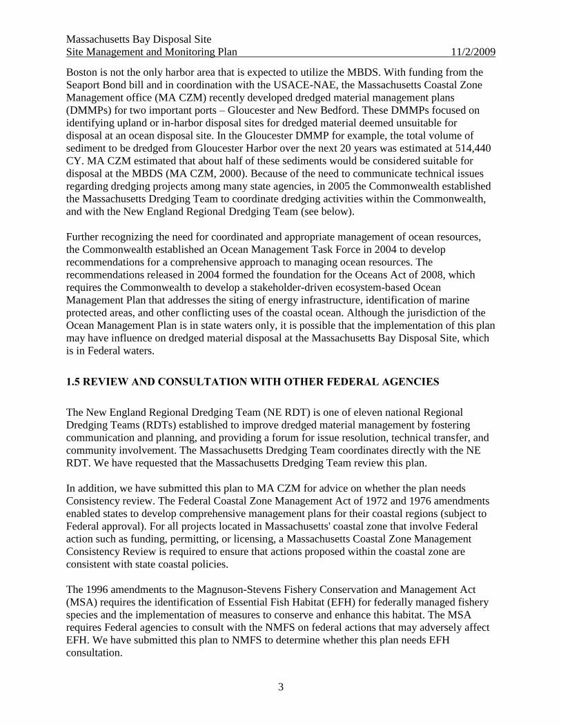
Boston is not the only harbor area that is expected to utilize the MBDS. With funding from the
Seaport Bond bill and in coordination with the USACE-NAE, the Massachusetts Coastal Zone
Management office (MA CZM) recently developed dredged material management plans
(DMMPs) for two important ports – Gloucester and New Bedford. These DMMPs focused on
identifying upland or in-harbor disposal sites for dredged material deemed unsuitable for
disposal at an ocean disposal site. In the Gloucester DMMP for example, the total volume of
sediment to be dredged from Gloucester Harbor over the next 20 years was estimated at 514,440
CY. MA CZM estimated that about half of these sediments would be considered suitable for
disposal at the MBDS (MA CZM, 2000). Because of the need to communicate technical issues
regarding dredging projects among many state agencies, in 2005 the Commonwealth established
the Massachusetts Dredging Team to coordinate dredging activities within the Commonwealth,
and with the New England Regional Dredging Team (see below).
Further recognizing the need for coordinated and appropriate management of ocean resources,
the Commonwealth established an Ocean Management Task Force in 2004 to develop
recommendations for a comprehensive approach to managing ocean resources. The
recommendations released in 2004 formed the foundation for the Oceans Act of 2008, which
requires the Commonwealth to develop a stakeholder-driven ecosystem-based Ocean
Management Plan that addresses the siting of energy infrastructure, identification of marine
protected areas, and other conflicting uses of the coastal ocean. Although the jurisdiction of the
Ocean Management Plan is in state waters only, it is possible that the implementation of this plan
may have influence on dredged material disposal at the Massachusetts Bay Disposal Site, which
is in Federal waters.
1.5 REVIEW AND CONSULTATION WITH OTHER FEDERAL AGENCIES
The New England Regional Dredging Team (NE RDT) is one of eleven national Regional
Dredging Teams (RDTs) established to improve dredged material management by fostering
communication and planning, and providing a forum for issue resolution, technical transfer, and
community involvement. The Massachusetts Dredging Team coordinates directly with the NE
RDT. We have requested that the Massachusetts Dredging Team review this plan.
In addition, we have submitted this plan to MA CZM for advice on whether the plan needs
Consistency review. The Federal Coastal Zone Management Act of 1972 and 1976 amendments
enabled states to develop comprehensive management plans for their coastal regions (subject to
Federal approval). For all projects located in Massachusetts' coastal zone that involve Federal
action such as funding, permitting, or licensing, a Massachusetts Coastal Zone Management
Consistency Review is required to ensure that actions proposed within the coastal zone are
consistent with state coastal policies.
The 1996 amendments to the Magnuson-Stevens Fishery Conservation and Management Act
(MSA) requires the identification of Essential Fish Habitat (EFH) for federally managed fishery
species and the implementation of measures to conserve and enhance this habitat. The MSA
requires Federal agencies to consult with the NMFS on federal actions that may adversely affect
EFH. We have submitted this plan to NMFS to determine whether this plan needs EFH
consultation.

Massachusetts Bay Disposal Site
Site Management and Monitoring Plan 11/2/2009
4
EPA has also requested that NMFS review this plan to determine whether an Endangered
Species Act Section 7 consultation is necessary. NMFS routinely conducts ESA and ESF
consultation on a project-by-project basis, not for management plans.
In addition, because the actions recommended in this plan are in the vicinity of the Stellwagen
Bank National Sanctuary, this plan must comply with Section 304(e) of the MPRSA as amended,
requiring consultation with the Stellwagen Bank National Marine Sanctuary office. This plan has
been submitted to the SBNMS for review.
2. ROLES, RESPONSIBILITIES AND AUTHORITIES
The primary Federal environmental statute governing transportation of dredged material for the
purpose of dumping it into ocean waters (seaward of the baseline of the territorial sea) is the
Marine Protection, Research, and Sanctuaries Act (MPRSA, also called the Ocean Dumping Act,
33 USC 1401 et seq.). The MPRSA assigns authority to both EPA and USACE in managing
disposal sites and issuing permits for ocean disposal.
2.1 FEDERAL REGULATORY/STATUTORY RESPONSIBILITIES
Under Section 103 (33 USC 1413) of the MPRSA, USACE is responsible for issuing permits for
disposal of dredged material, subject to EPA review and concurrence. The EPA, however, is
charged with developing ocean dumping criteria to be used in evaluating permit applications
[MPRSA §102(a)]. Disposal must not ―unreasonably degrade or endanger human health, welfare,
or amenities, or the marine environment, ecological systems, or economic potentialities‖. The
ocean dumping regulations in 40 CFR Parts 227 and 228 provide a testing framework to apply
these criteria and determine whether dredged material is environmentally acceptable (or suitable)
for open ocean disposal. USACE is required to use EPA designated open-water disposal sites for
dredged material disposal to the maximum extent feasible2. Proposed ocean disposal of dredged
material also must comply with USACE permitting and dredging regulations in 33 CFR Parts
320 to 330 and 335 to 338.
Other primary authorities that apply to the disposal of dredged material in the United States are
the Rivers and Harbors Act of 1899 (RHA), and the Water Resources Development Act
(WRDA) of 1992 (and subsequent legislation). The RHA regulates dredging and discharge of
material in navigable waters and WRDA addresses research and funding in support of specific
water resource projects for various needs (i.e., transportation, recreation). WRDA also modifies
other Acts, as necessary (e.g., MPRSA).
2 If a designated disposal site is not feasible, the USACE can ―select‖ an alternative ocean disposal site under
Section 103 of the MPRSA for two successive five year periods.
Massachusetts Bay Disposal Site
Site Management and Monitoring Plan 11/2/2009
5
2.2 SURVEILLANCE AND ENFORCEMENT
All dredging, dredged material transport, and disposal must be conducted in compliance with
USACE permits issued for these activities. Under the MPRSA§105 (33 USC 1415), the EPA
takes the lead in surveillance and enforcement responsibilities at the disposal site with assistance
from the USACE and the U.S. Coast Guard (see 33 USC Sec 1417[c]). The permittee is
responsible for ensuring compliance with all project conditions including placement of material
at the correct location and within applicable site use restrictions. An example of permit
conditions is included in Section 7.2.
Disposal locations are marked with a taut-wire buoy or specified coordinates to ensure that
disposal locations are known and that post-disposal monitoring is effective. The USACE-NAE
Disposal Area Monitoring System (DAMOS) Manager determines the specific location for
disposal of dredged material at the site (see Section 7.3).
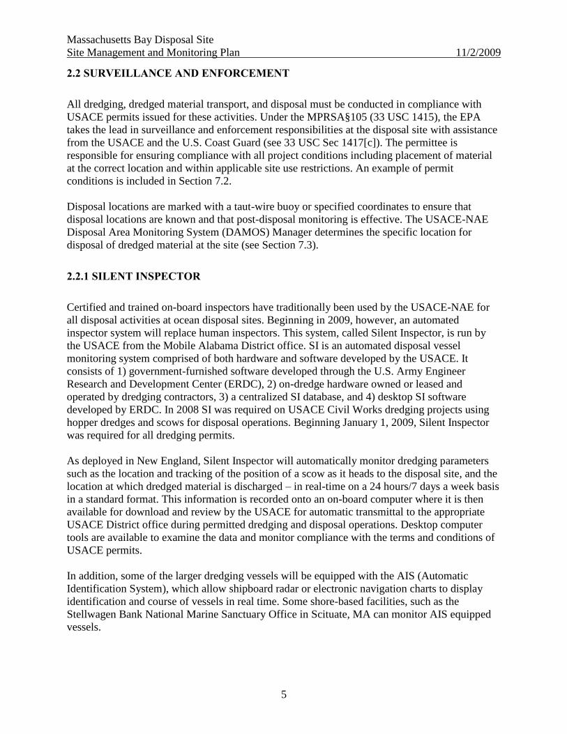
2.2.1 SILENT INSPECTOR
Certified and trained on-board inspectors have traditionally been used by the USACE-NAE for
all disposal activities at ocean disposal sites. Beginning in 2009, however, an automated
inspector system will replace human inspectors. This system, called Silent Inspector, is run by
the USACE from the Mobile Alabama District office. SI is an automated disposal vessel
monitoring system comprised of both hardware and software developed by the USACE. It
consists of 1) government-furnished software developed through the U.S. Army Engineer
Research and Development Center (ERDC), 2) on-dredge hardware owned or leased and
operated by dredging contractors, 3) a centralized SI database, and 4) desktop SI software
developed by ERDC. In 2008 SI was required on USACE Civil Works dredging projects using
hopper dredges and scows for disposal operations. Beginning January 1, 2009, Silent Inspector
was required for all dredging permits.
As deployed in New England, Silent Inspector will automatically monitor dredging parameters
such as the location and tracking of the position of a scow as it heads to the disposal site, and the
location at which dredged material is discharged – in real-time on a 24 hours/7 days a week basis
in a standard format. This information is recorded onto an on-board computer where it is then
available for download and review by the USACE for automatic transmittal to the appropriate
USACE District office during permitted dredging and disposal operations. Desktop computer
tools are available to examine the data and monitor compliance with the terms and conditions of
USACE permits.
In addition, some of the larger dredging vessels will be equipped with the AIS (Automatic
Identification System), which allow shipboard radar or electronic navigation charts to display
identification and course of vessels in real time. Some shore-based facilities, such as the
Stellwagen Bank National Marine Sanctuary Office in Scituate, MA can monitor AIS equipped
vessels.
Massachusetts Bay Disposal Site
Site Management and Monitoring Plan 11/2/2009
6
Because of the proximity of the MBDS to Stellwagen Bank, however, marine mammal observers
will still be required on all disposal activities between February 1 and May 30 (See permit
conditions in Section 7.2).
2.2.2 MONITORING
The USACE and EPA share responsibility for monitoring of the site and will use the SMMP to
guide the monitoring at the site. Monitoring data from other agencies will be utilized as
appropriate to maximize the availability of information at the site. Under MPRSA, EPA has the
responsibility for determining if an unacceptable impact has occurred as a result of dredged
material disposal at the site and for determining any modification to site use or de-designation.
Such determinations, however, will be made in consultation with other agencies. The USACE
and EPA share responsibility for developing any necessary mitigation plan.
Monitoring surveys at and near the site will be conducted periodically as available funding
permits. The monitoring objective for each survey will be based on the SMMP, prior monitoring
results and, if appropriate, recommendations of the New England Regional Dredging Team or
Massachusetts Dredging Team.
3. BACKGROUND
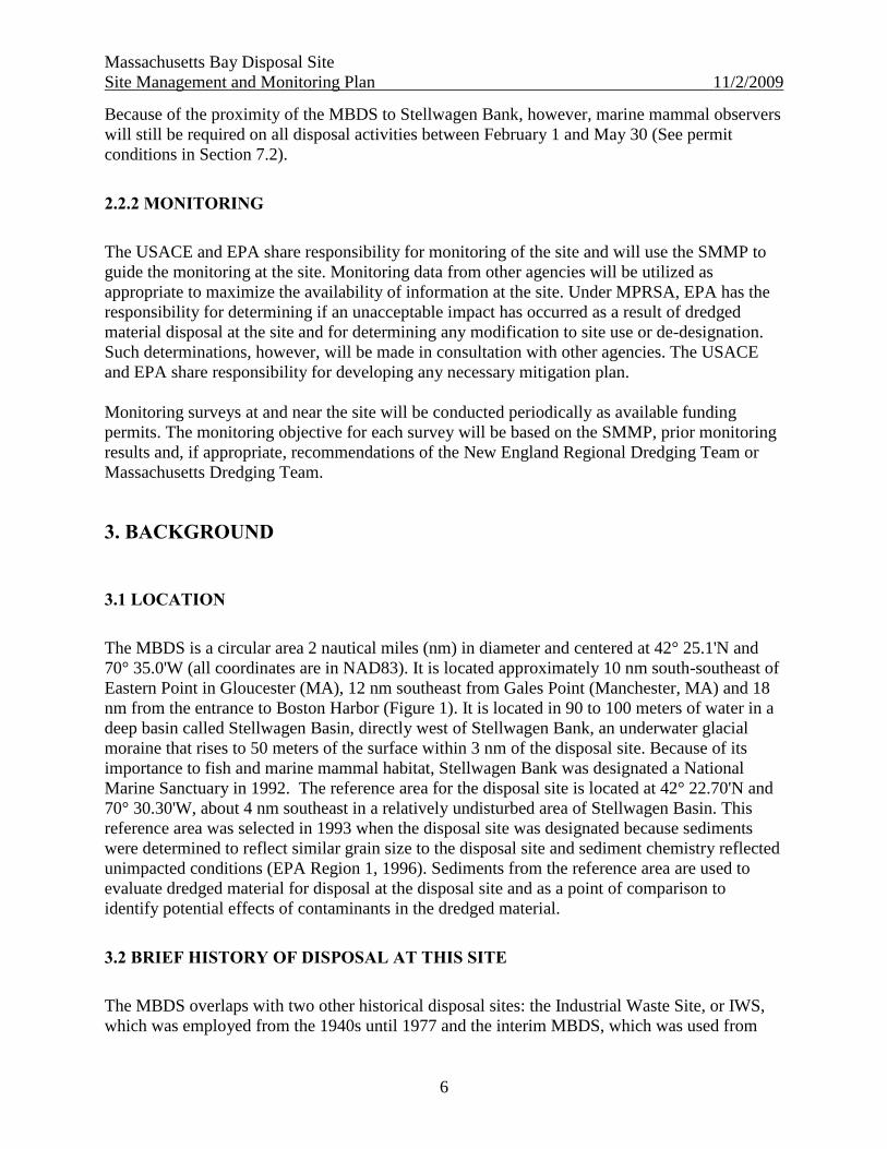
3.1 LOCATION
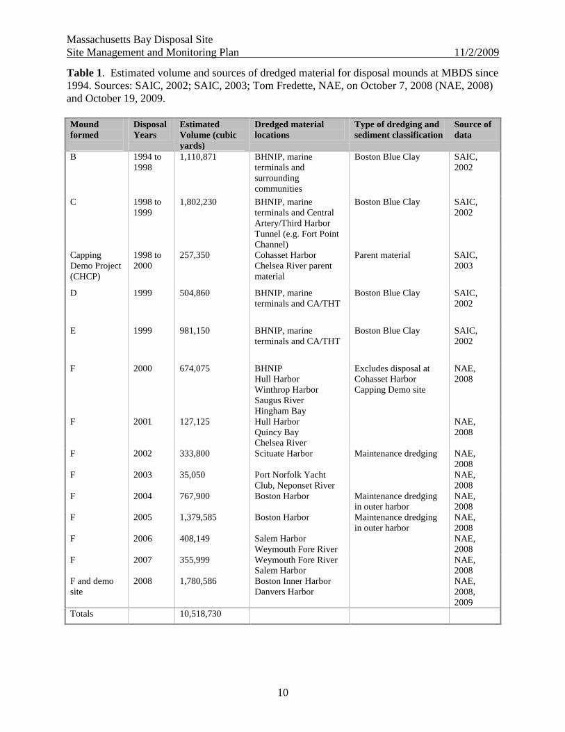
The MBDS is a circular area 2 nautical miles (nm) in diameter and centered at 42° 25.1'N and
70° 35.0'W (all coordinates are in NAD83). It is located approximately 10 nm south-southeast of
Eastern Point in Gloucester (MA), 12 nm southeast from Gales Point (Manchester, MA) and 18
nm from the entrance to Boston Harbor (Figure 1). It is located in 90 to 100 meters of water in a
deep basin called Stellwagen Basin, directly west of Stellwagen Bank, an underwater glacial
moraine that rises to 50 meters of the surface within 3 nm of the disposal site. Because of its
importance to fish and marine mammal habitat, Stellwagen Bank was designated a National
Marine Sanctuary in 1992. The reference area for the disposal site is located at 42° 22.70'N and
70° 30.30'W, about 4 nm southeast in a relatively undisturbed area of Stellwagen Basin. This
reference area was selected in 1993 when the disposal site was designated because sediments
were determined to reflect similar grain size to the disposal site and sediment chemistry reflected
unimpacted conditions (EPA Region 1, 1996). Sediments from the reference area are used to
evaluate dredged material for disposal at the disposal site and as a point of comparison to
identify potential effects of contaminants in the dredged material.
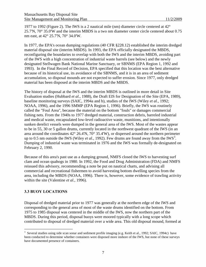
3.2 BRIEF HISTORY OF DISPOSAL AT THIS SITE
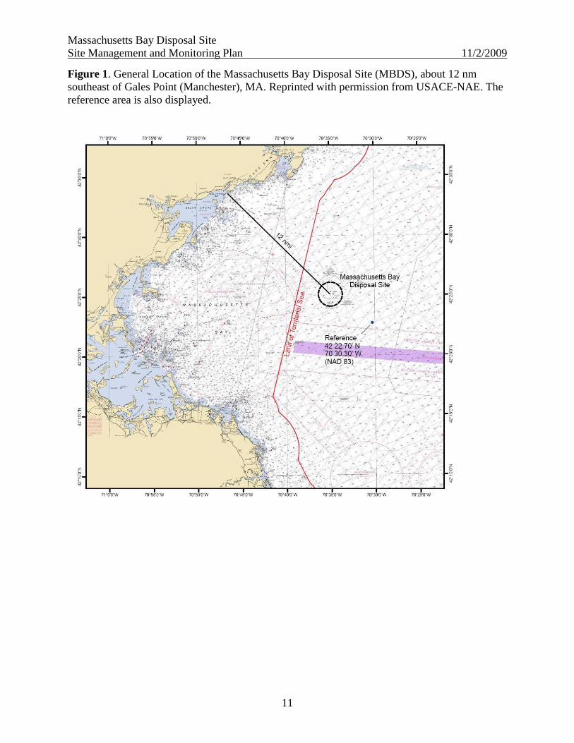
The MBDS overlaps with two other historical disposal sites: the Industrial Waste Site, or IWS,
which was employed from the 1940s until 1977 and the interim MBDS, which was used from
Massachusetts Bay Disposal Site
Site Management and Monitoring Plan 11/2/2009
7
1977 to 1992 (Figure 2). The IWS is a 2 nautical mile (nm) diameter circle centered at 42°
25.7'N, 70° 35.0'W and the interim MBDS is a two nm diameter center circle centered about 0.75
nm east, at 42° 25.7'N, 70° 34.0'W.
In 1977, the EPA's ocean dumping regulations (40 CFR §228.12) established the interim dredged
material disposal site (interim MBDS). In 1993, the EPA officially designated the MBDS,
reconfiguring the boundaries to overlap with both the IWS and the interim MBDS, avoiding part
of the IWS with a high concentration of industrial waste barrels (see below) and the newly
designated Stellwagen Bank National Marine Sanctuary, or SBNMS (EPA Region 1, 1992 and
1993). In the Final Record of Decision, EPA specified that this location was the best alternative
because of its historical use, its avoidance of the SBNMS, and it is in an area of sediment
accumulation, so disposal mounds are not expected to suffer erosion. Since 1977, only dredged
material has been disposed at the interim MBDS and the MBDS.
The history of disposal at the IWS and the interim MBDS is outlined in more detail in Site
Evaluation studies (Hubbard et al., 1988), the Draft EIS for Designation of the Site (EPA, 1989),
baseline monitoring surveys (SAIC, 1994a and b), studies of the IWS (Wiley et al., 1992;
NOAA, 1996), and the 1996 SMMP (EPA Region 1, 1996). Briefly, the IWS was routinely
called the "Foul Area", because the material on the bottom "fouls" or damages commercial
fishing nets. From the 1940s to 1977 dredged material, construction debris, barreled industrial
and medical waste, encapsulated low-level radioactive waste, munitions, and intentionally
sunken derelict vessels were dumped in the general area of the IWS. Most of the wastes appear
to be in 55, 30 or 5 gallon drums, currently located in the northwest quadrant of the IWS (in an
area around the coordinates 42° 26.4'N, 70° 35.4'W), or dispersed around the northern perimeter
up to 0.5 nm outside the IWS (Wiley et al., 1992). Few drums are found away from the IWS3.
Dumping of industrial waste was terminated in 1976 and the IWS was formally de-designated on
February 2, 1990.
Because of this area's past use as a dumping ground, NMFS closed the IWS to harvesting surf
clam and ocean quahogs in 1980. In 1992, the Food and Drug Administration (FDA) and NMFS
reissued this advisory, recommending a note be put on nautical charts, and advising all
commercial and recreational fishermen to avoid harvesting bottom dwelling species from the
area, including the MBDS (NOAA, 1996). There is, however, some evidence of trawling activity
within the site (Valentine et al., 1996).
3.3 BUOY LOCATIONS
Disposal of dredged material prior to 1977 was generally at the northern edge of the IWS and
corresponding to the general area of most of the waste drums identified on the bottom. From
1975 to 1985 disposal was centered in the middle of the IWS, now the northern part of the
MBDS. During this period, disposal buoys were moored typically with a long scope which
contributed to disposal of dredged material over a wide area. This old disposal mound, formed at
3 Several studies using side scan sonar and sediment profile imaging (e.g. Keith et al., 1992; SAIC, 1994c) have
been conducted to determine whether containers were disposed more inshore of the IWS, but none of these surveys
have documented presence of containers.
Massachusetts Bay Disposal Site
Site Management and Monitoring Plan 11/2/2009
8
the location of the old ―BFG‖ buoy from 1975 to 1985 (see the 1996 SMMP for locations and
names of former buoys) is slightly visible in Figure 2.
In November 1985, a taut-wired disposal buoy called MDA, maintained by NAE, was deployed
near 42° 25.1'N, 70° 34.45'W in the southwestern quadrant of the interim MBDS (Hubbard et al.,
1988). Although the new MBDS was reconfigured in 1993, the buoy was not moved at that time.
This buoy and all subsequent taut wire buoys have provided greater precision in disposal, and
defined mounds on the bottom have resulted.
Mound A was formed from dredged material disposal through 1994 at the MDA buoy and is
clearly seen (Figure 3) in an acoustic survey of the sea floor in 1996. This figure is based on
composite images in which backscatter and sun-illuminated images have been combined to show
the composition of the sea bed and the topographic relief. Sun-illumination is from the north.
Blue represents low backscatter mud of Stellwagen Basin, and orange represents high
backscatter gravelly sand and cobbles and boulders of Stellwagen Bank. Green represents
moderate backscatter deposits of dredged material and similarly reflective materials on many of
the higher geologic pinnacles. The green mound in the middle of the image is located at the
disposal point being used during that time period. Red represents very high backscatter deposits
of rock debris from the excavation of the Ted Williams Tunnel beneath Boston Harbor.
In addition to a sediment dredged material disposal buoy, a Rock Reef Site (called the Rock
Disposal Location in the 1996 SMMP) was established in 1991 specifically for disposal of rocks
generated from downtown Boston's "Central Artery/Third Harbor Tunnel" and two other smaller
projects. The purpose of this disposal was to provide habitat diversity over a homogeneous silty
sand substrate at the western edge of Stellwagen Bank (SAIC, 2004). This location (which was
marked only by coordinates, and not by a buoy) was in the northeast quadrant of the interim
MBDS (about 500 meters outside of the new MBDS), on the slope of Stellwagen Bank at the
coordinates 42° 26.5'N, 70° 34.0'W at 50 m depth (Figures 2 and 3). This location is now
outside the current boundary of the MBDS and will not be used for future disposal.
Since 1994 the buoy, renamed as the MBDA buoy, has been moved to create a ring of defined
disposal mounds surrounding a shallow depression in the northeast quadrant of the site. The
purpose of this strategy is to construct a boundary of a ―containment cell‖ that would potentially
limit the lateral spread of future dredged material (ENSR, 2005). Six mounds have been created,
Mounds A to F and CHCP (Cohasset Harbor Capping Project), revealed in Figures 4 and 5 based
on bathymetry collected in 2004.
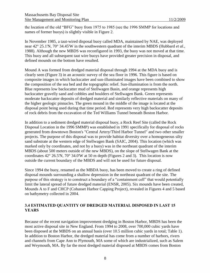
3.4 ESTIMATED QUANTITY OF DREDGED MATERIAL DISPOSED IN LAST 15
YEARS
Because of the recent navigation improvement dredging in Boston Harbor, MBDS has been the
most active disposal site in New England. From 1994 to 2008, over 700,000 cubic yards have
been disposed at the MBDS on an annual basis (over 10.5 million cubic yards in total; Table 1).
In addition to Boston Harbor, the dredged material has come from a number of harbors, rivers
and channels from Cape Ann to Plymouth, MA some of which are industrialized, such as Salem
and Weymouth, MA. By far the most dredged material disposed at MBDS comes from Boston

Massachusetts Bay Disposal Site
Site Management and Monitoring Plan 11/2/2009
9
Harbor and this trend is expected to continue. Below is a recent history of major dredging
projects in Boston Harbor.
1992 to 1993: About 1.5 million cubic yards of sediment (primarily Boston Blue Clay) and
blasted rocks from the Central Artery/Third Harbor Tunnel (now called the Ted Williams
Tunnel) project were disposed at the MDA buoy and the Rock Reef Site.
1997 to 2001: Over 300,000 cubic yards of soft surface sediment material and bottom clays from
Fort Point Channel in downtown Boston was dredged for the Central Artery/THT project.
Unsuitable material was disposed at Spectacle Island, and the remaining clean material (mostly
clays from parent material) was disposed at the MBDS (SAIC, 2002).
1997 to 2000: Over 2 million cubic yards of sediment and clean parent material (―Boston Blue
Clay‖) from the inner harbor was dredged as part of the Boston Harbor Navigation Improvement
Project (BHNIP) and disposed at the MBDS. Confined Aquatic Disposal (CAD) cells were
constructed within the Mystic and Chelsea rivers and inner harbor to contain approximately one
million cubic yards of unsuitable material contaminated with metals and organic compounds
(ENSR, 2007).
1998 to 2000: The US Army Corps of Engineers New England District conducted a
demonstration project to evaluate the feasibility of capping a discrete mound of sediment on the
seafloor of the MBDS. Two distinct types of dredged material, one from Cohasset Harbor, and
―capping material‖ from the Chelsea River, were dredged and sequentially disposed at a location
within the MBDS in an area removed from the ongoing mounds in the center of the disposal site.
The Cohasset Harbor Capping Project (CHCP) mound was centered at about 42° 24.45'N and
70° 34.73'W in the southern part of the MBDS and received about 74,250 cubic yards of sandy
silt and clay material from Cohasset Harbor, and about 201,900 cubic yards of acceptable
material, mostly clumps of Boston Blue Clay and sand and gravel, from the Chelsea River as part
of the BHNIP. Results of several surveys using side scan sonar, bathymetry and sediment cores
determined that the capped material appeared to sufficiently cover the ―unsuitable‖ material
(SAIC, 2003)4.
2004 and 2005: Approximately 1.1 million cubic yards of maintenance material was removed
from the Broad Sound North Channel, President Roads Channel and Anchorage and portions of
the Main Ship Channel in the outer harbor (USACE/MassPort, 2006).
2008: Over 1,700,000 cubic yards of material were dredged in the inner harbor as part of the
Boston Harbor Navigation Improvement Program. About 900,000 cubic yards were disposed at
Mound F and about 800,000 cubic yards were disposed at the demonstration site in the western
part of the MBDS (see section 6.1).
4 Unsuitable material is prohibited from disposal at the MBDS. See section 6.3.
Massachusetts Bay Disposal Site
Site Management and Monitoring Plan 11/2/2009
10
Table 1. Estimated volume and sources of dredged material for disposal mounds at MBDS since
1994. Sources: SAIC, 2002; SAIC, 2003; Tom Fredette, NAE, on October 7, 2008 (NAE, 2008)
and October 19, 2009.
Mound
formed
Disposal
Years
Estimated
Volume (cubic
yards)
Dredged material
locations
Type of dredging and
sediment classification
Source of
data
B 1994 to
1998
1,110,871 BHNIP, marine
terminals and
surrounding
communities
Boston Blue Clay SAIC,
2002
C 1998 to
1999
1,802,230 BHNIP, marine
terminals and Central
Artery/Third Harbor
Tunnel (e.g. Fort Point
Channel)
Boston Blue Clay
SAIC,
2002
Capping
Demo Project
(CHCP)
1998 to
2000
257,350 Cohasset Harbor
Chelsea River parent
material
Parent material SAIC,
2003
D 1999 504,860 BHNIP, marine
terminals and CA/THT
Boston Blue Clay SAIC,
2002
E 1999 981,150 BHNIP, marine
terminals and CA/THT
Boston Blue Clay SAIC,
2002
F 2000 674,075
BHNIP
Hull Harbor
Winthrop Harbor
Saugus River
Hingham Bay
Excludes disposal at
Cohasset Harbor
Capping Demo site
NAE,
2008
F 2001 127,125 Hull Harbor
Quincy Bay
Chelsea River
NAE,
2008
F 2002 333,800 Scituate Harbor Maintenance dredging NAE,
2008
F 2003 35,050 Port Norfolk Yacht
Club, Neponset River
NAE,
2008
F 2004 767,900 Boston Harbor Maintenance dredging
in outer harbor
NAE,
2008
F 2005 1,379,585 Boston Harbor Maintenance dredging
in outer harbor
NAE,
2008
F 2006 408,149
Salem Harbor
Weymouth Fore River
NAE,
2008
F 2007 355,999 Weymouth Fore River
Salem Harbor
NAE,
2008
F and demo
site
2008 1,780,586
Boston Inner Harbor
Danvers Harbor
NAE,
2008,
2009
Totals 10,518,730
Massachusetts Bay Disposal Site
Site Management and Monitoring Plan 11/2/2009
11
Figure 1. General Location of the Massachusetts Bay Disposal Site (MBDS), about 12 nm
southeast of Gales Point (Manchester), MA. Reprinted with permission from USACE-NAE. The
reference area is also displayed.
Massachusetts Bay Disposal Site
Site Management and Monitoring Plan 11/2/2009
12
Figure 2. Location of Massachusetts Bay Disposal Site (Black circle) in relation to the Interim
Massachusetts Bay Disposal Site (Blue circle) and Industrial Waste Site (Red circle). Base map
source: Sun-illuminated backscatter topography of Massachusetts Bay Disposal Site, with
Industrial Waste Site and interim MBDS identified, Butman and Lindsay, 1999.
Interim MBDS
1977 to 1992
MBDS
1992 to present
IWS
1940s to 1977
Mound A
―BFG‖ Area
MoundMoundMo
undmound
Rock Reef Site

Massachusetts Bay Disposal Site
Site Management and Monitoring Plan 11/2/2009
13
Figure 3. Backscatter image of Massachusetts Bay Disposal Site created from multibeam
bathymetric data in 1996. Note that in this image, the ―mound at the active disposal point‖ is
Mound A formed from 1985 to 1996 and the ―mound at the old disposal site‖ is the old ―BFG‖
area. These mounds are also visible in some of the images generated by USGS (see Figure 2).
This is the location for disposal from 1975 to 1985. Source: Valentine et al. (1998). The
approximate boundary of the current MBDS has been placed on this image.

Massachusetts Bay Disposal Site
Site Management and Monitoring Plan 11/2/2009
14
Figure 4. Bathymetric contour map of MBDS survey area, September 2004 (2-m contour
interval) showing disposal buoy positions between 1993 and 2004 and resulting disposal mounds
formed on the MBDS seafloor. Source: ENSR, 2005. Reprinted with permission.

Massachusetts Bay Disposal Site
Site Management and Monitoring Plan 11/2/2009
15
Figure 5. Locations of disposal events in MBDS from 1984 to 2007 (shown as green dots)
overlain on bathymetry of MBDS determined in 2004 using a narrow beam echosounder (shown
by the blue contours at 0.5 meter intervals). The solid blue area near the northern intersection of
black and blue circles is a natural topographic high (drumlin) shown in Figure 2. Source of data:
personal communication from Stephanie Wilson, ENSR based on coordinates from NAE scow
logs and bathymetry from ENSR, 2005.
CHCP
Mound A
Mound C
Mound F Mound B
Mound D
Mound E
Massachusetts Bay Disposal Site
Site Management and Monitoring Plan 11/2/2009
16
4. BASELINE ASSESSMENT
4. 1 GENERAL PHYSICAL, CHEMICAL AND BIOLOGICAL CHARACTERISTICS
Much of the basic physical, chemical, and biological characteristics of the MBDS have been
evaluated and described in previous documents, such as Hubbard et al. (1988), EPA Region 1
(1989) and Butman et al. (1992) and summarized in the 1996 SMMP (EPA Region 1, 1996).
Recent studies by the MWRA, USGS, NOAA and EPA (respectively Hunt et al., 2006, Bothner
and Butman 2005 and 2007; NOAA NCCOS, 2006; Liebman and Brochi, 2008) corroborate
many of these observations, and provide additional information.
4.1.1 PHYSICAL SETTING AND CIRCULATION
The Massachusetts Bay Disposal Site lies in 90 to 100 meters of water in the northwest corner of
Stellwagen Basin -- a large depression within Massachusetts Bay separated from the Gulf of
Maine by Stellwagen Bank, a sand and gravel underwater shelf which rises to the east to within
50 meters of the surface (Figure 6). From side scan sonar and bathymetry images, the bottom is
generally flat with a small circular depression in the northeast quadrant of the site and a glacial
knoll at the northern boundary. Within 1,000 meters of the northeast edge are the steep flanks of
Stellwagen Bank. Because of the topography of the bank, nutrient rich deep water mixes with
shallower bank water resulting in heightened seasonal productivity and a rich fishing area.
Stellwagen Bank is habitat, feeding ground, and a nursery area for 22 species of marine
mammals, 34 species of seabirds, and over 80 fish species (NOAA NMSP, 2008).
Because of the semi-enclosed geometry of Massachusetts Bay caused by Stellwagen Bank and
Cape Cod, local bottom currents are relatively slow, averaging about four to seven cm/second.
Modeling and measurements of bottom circulation in Stellwagen Basin during storm events from
the northeast suggest that bottom currents would increase to 30 cm/sec over a short period of
time (i.e. one to two days once every four years or so). These flows are not high enough to cause
significant resuspension of dredged material; only a small portion of the non-cohesive silty
sediments are expected to be resuspended under these conditions. MBDS is located in an area of
Massachusetts Bay most buffered from the effects of winter storms (Butman et al., 2004). Based
on hydrodynamic and sediment transport modeling of Massachusetts Bay, the MBDS is in a
depositional area (Figure 7). Fine-grained sediments accumulate after transport by storm-driven
wind and circulation patterns (Bothner and Butman, 2007). Based on vertical profiles, sediments
accumulate at about 0.1 to 0.2 cm/year (Wade, 1989).

Massachusetts Bay Disposal Site
Site Management and Monitoring Plan 11/2/2009
17
Figure 6. Topography of Massachusetts Bay, in shaded relief view, colored by water depth,
based on multibeam surveys and the NOAA Coastal Relief Model. The image accentuates small
features that could not be effectively shown by contours alone at this scale. From Bothner and
Butman, 2007. Reprinted with permission.
Approximate MBDS location

Massachusetts Bay Disposal Site
Site Management and Monitoring Plan 11/2/2009
18
Figure 7. Observed surficial sediment grain size distribution in Massachusetts Bay. The MBDS
is in an area of 5 to 6 phi units, which is considered medium silts (larger phi units are associated
with finer sediments). From Figure 6.5 in Bothner and Butman, 2007, based on Poppe, 2003.
Reprinted with permission.
Approximate MBDS location
Massachusetts Bay Disposal Site
Site Management and Monitoring Plan 11/2/2009
19
4.1.2 SEDIMENT CHARACTERISTICS
The most common grain size at the MBDS and surrounding area is silty-sand, with a mean phi
size of 4 to 5 but ranging from 3 to 7. Recent observations of the sediments in the disposal
mound and reference areas undisturbed by dredged material disposal ranged from about 75 to
90% silt-clay (Liebman and Brochi, 2008).
Marine sediments in general are characterized by an oxidized surface later that transitions to a
redox potential discontinuity (RPD) to the underlying anoxic sediments. The RPD denotes the
depth where chemical reduction/oxidation (redox) potentials decrease rapidly, in some areas to
negative values. The aerobic sediments above this zone are generally supportive of diverse
benthic organisms, while the anaerobic sediments below are generally less diverse. For sediment
unaffected by dredged material at the MBDS, apparent RPD depths (measured using the
sediment profile camera) range from two to seven cm with a majority in the four to six cm range.
Areas with freshly disposed dredged material typically exhibit shallower apparent RPD depths
(0.5 to 2 cm) than fully recolonized mounds or reference areas (SAIC, 1990b, SAIC, 1994a).
Measurements of total organic carbon (TOC; a measure of organic matter content) in reference
areas range from 2.5 to 3.2%, but on dredged material mounds with the presence of cohesive
clumps of clay material, TOC ranges from 0.5% to 2.5%, with a mean of about 1.0% (Hubbard et
al., 1988, SAIC, 1990b, SAIC, 1994a, Liebman and Brochi, 2008).
Benthic nutrient and sediment oxygen measurements at a station in Stellwagen Basin exhibit
―highly oxic conditions‖ and have not changed significantly in the last ten years (Tucker et al.,
2006). Compared to sediments collected in shallower waters in Massachusetts Bay which
experienced a coarsening of grain size and decreases in organic matter, sediments collected from
Stellwagen Basin showed little effects of the two significant storms in May 2005.
4.1.3 SEDIMENT CHEMISTRY
Because the MBDS is located in a settling basin, suspended sediments and associated (adsorbed)
contaminants transported from regional sources can accumulate there (Bothner and Butman,
2005 and 2007). Vertical sediment profiles from cores in Stellwagen Basin reflect the long-term
history of contamination in Massachusetts Bay (Wade et al., 1989). Sediment contamination at
the MBDS, however, is likely attributed to historic disposal of dredged material.
Monitoring prior to 1996 reveals the history of disposal at the MBDS and the IWS. Historical
use of the old ―BFG‖ buoy area and the IWS resulted in 1) slightly elevated toxicant levels and
bioaccumulation in sediments west of the old "BFG" buoy (Station 12-3 in SAIC, 1997) and in
the IWS (EPA Region 1, 1996), and 2) elevated polycyclic aromatic hydrocarbon (PAH) and
polychlorinated biphenyl (PCB) levels in lobster tomalley collected from the IWS and MBDS
area (Hubbard et al., 1988; NOAA, 1996). Tissue burdens in edible fish, however, were low and
do not appear to pose a human health risk. Levels of radionuclides in sediments and biota are not
above background (NOAA, 1996).
Massachusetts Bay Disposal Site
Site Management and Monitoring Plan 11/2/2009
20
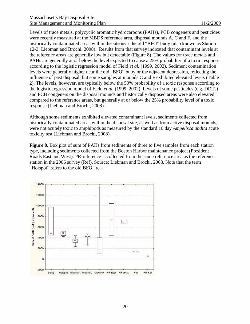
Levels of trace metals, polycyclic aromatic hydrocarbons (PAHs), PCB congeners and pesticides
were recently measured at the MBDS reference area, disposal mounds A, C and F, and the
historically contaminated areas within the site near the old ―BFG‖ buoy (also known as Station
12-3; Liebman and Brochi, 2008). Results from that survey indicated that contaminant levels at
the reference areas are generally low but detectable (Figure 8). The values for trace metals and
PAHs are generally at or below the level expected to cause a 25% probability of a toxic response
according to the logistic regression model of Field et al. (1999, 2002). Sediment contamination
levels were generally higher near the old ―BFG‖ buoy or the adjacent depression, reflecting the
influence of past disposal, but some samples at mounds C and F exhibited elevated levels (Table
2). The levels, however, are typically below the 50% probability of a toxic response according to
the logistic regression model of Field et al. (1999, 2002). Levels of some pesticides (e.g. DDTs)
and PCB congeners on the disposal mounds and historically disposed areas were also elevated
compared to the reference areas, but generally at or below the 25% probability level of a toxic
response (Liebman and Brochi, 2008).
Although some sediments exhibited elevated contaminant levels, sediments collected from
historically contaminated areas within the disposal site, as well as from active disposal mounds,
were not acutely toxic to amphipods as measured by the standard 10 day Ampelisca abdita acute
toxicity test (Liebman and Brochi, 2008).
Figure 8. Box plot of sum of PAHs from sediments of three to five samples from each station
type, including sediments collected from the Boston Harbor maintenance project (President
Roads East and West). PR-reference is collected from the same reference area as the reference
station in the 2006 survey (Ref). Source: Liebman and Brochi, 2008. Note that the term
―Hotspot‖ refers to the old BFG area.

Massachusetts Bay Disposal Site
Site Management and Monitoring Plan 11/2/2009
21
Table 2. Highest observed levels of metals (ug/g) and sum PCBs (ug/g) compared to sediment
screening levels applied in US EPA, 2004. P25% and P50% are the concentrations that would
give a 25% or 50% probability of a toxic response according to the logistic regression model of
Field et al. (1999, 2002).
Analyte
Highest
observed
value (ug/g
dry weight)
Mound
or area
Highest
observed
median value
(ug/g dry
weight)
Mound
or area
P25%
(ug/g dry
weight)
P50%
(ug/g dry
weight)
Arsenic 14 Ref 13 C 11.29 32.61
Cadmium 1.9 C 1.65 BFG 0.65 2.49
Chromium 170 C 150 Deep 76.00 233.27
Copper 87 C 75 Deep 49.98 157.13
Lead 75 C 66 Deep 47.82 161.06
Mercury 0.63 Deep 0.43 Deep 0.23 0.87
Nickel 34 F 30 F 23.77 80.07
Zinc 240 F 140 Deep 140.48 383.81
Sum PCBs 0.336 F 0.207 F 0.09 1.12
Sum PAHs 13.469 F 4.884 Deep n/a n/a
DDT 0.0057 F 0.002 BFG 0.004 0.03
4.1.4 BIOLOGICAL CHARACTERISTICS OF BENTHIC COMMUNITIES
Stellwagen Basin sediments are dominated by benthic infauna characterized by polychaetes and
mollusks (EPA Region 1, 1996). At disposal sites in New England, benthic infauna generally
recolonize new sediment and fresh dredged material in a relatively predictable sequence,
characterized by three stages of succession (Rhoads and Germano, 1986). The first stage (or
―sere‖; Stage I) is dominated by small, opportunistic, tube-forming, capitellid, spionid, and
paraonid polychaetes or oligochaetes which rapidly (i.e., within 1 to 2 weeks) colonize new
disposal mounds and which do not penetrate into the sediments very deeply. These organisms are
thought to be recruited to the new habitat from off the disposal mound. Stage II is dominated by
deeper penetrating species, which include tubicolous amphipods (e.g., Ampelisca abdita), and
mollusks, typically occurring 3-6 months after disposal has ceased. These taxa represent a more
transitional stage, and they may or may not hold permanent positions in the long term benthic
community structure. Stage III animals represent an "equilibrium" level, typified by deeper-
dwelling, head-down deposit feeding species [e.g., maldanid (Clymenella zonalis) and pectinid
polychaetes, holothurians, and nuculid bivalves (Yoldia spp.), and predatory polychaetes, such as
Nephtys incisa]. This stage can also occur during the first year after dumping, but additional time
Massachusetts Bay Disposal Site
Site Management and Monitoring Plan 11/2/2009
22
for larval recruitment from off-site locations may be required. Some head-down deposit feeders
are thought to be capable of migrating up through the fresh dredged material after a disposal
event to maintain position in the sediment. It is common to find more than one successional stage
present at any one location (e.g., a Stage I community coexisting above a Stage III community).
Repeated disposal at one location in the site may keep the benthic community in a Stage I or II
community; less frequent disposal may allow a Stage III community to develop. These
communities can be "remotely" observed with a sediment profile imaging camera (see Section
5.3), but more accurate community analysis requires sieving, sorting and identification of all taxa
in a grab sample.
4.1.5 WATER COLUMN CHARACTERISTICS
From May to October, the water column is typically stratified, with the pycnocline located at
approximately 15 to 20 meters. Bottom water temperatures vary from about 3 to 5 °C. There is
little exchange of water between the bottom waters of Stellwagen Basin and the surface waters of
adjacent Stellwagen Bank, especially during the summer stratified period.
Recent studies conducted by the Massachusetts Water Resources Authority (MWRA) and the
USGS have confirmed and supplemented many of the observations made in the early 1990s
(Werme and Hunt, 2006; Bothner and Butman, 2005 and 2007). The MWRA has collected water
quality and benthic samples near (about 2.5 and 3 nm respectively) the MBDS. These samples
indicate that since monitoring began in 1992, average dissolved oxygen levels in the bottom
waters of Stellwagen Basin rarely go below 6.5 mg/liter indicating excellent water quality (Libby
et al., 2006). Levels of nutrients (specifically nitrate) in surface waters of offshore Massachusetts
Bay, however, have increased slightly over the last 12 years (Libby et al., 2006). This increase
has been seen regionally, and is not attributed to the discharge of the MWRA outfall in western
Massachusetts Bay (or disposal of dredged material). Although these increases in nutrients are
not associated with increases in annual chlorophyll levels in the Bay, there has been an increase
in the incidence or duration of harmful algal blooms – specifically Alexandrium, and Phaeocystis
-- in the last decade (Werme and Hunt, 2006; Libby et al., 2006). The Alexandrium blooms in
Massachusetts Bay have been strongly influenced by several ―Nor’easters‖, storms which
brought significant amounts of cells into Massachusetts Bay in May 2005, and then again in May
2008. The causes of increased frequency and duration of the regional Phaeocystis blooms are not
well understood.
4.1.6 EPIFAUNA AND FISHERIES
The 1996 SMMP (EPA Region 1, 1996) describes in detail important epifauna and fisheries at
the MBDS. Dominant epifauna include brittle stars, and flatfish, such as the American plaice,
plus commercially and recreationally important winter flounder, cod and spiny dogfish. Hard
bottom species include bryozoans, sponges and tunicates (SAIC, 2004).
Based on recent spring and fall bottom trawls conducted by the Massachusetts Division of
Marine Fisheries (MA DMF) in Massachusetts Bay, the most dominant (by weight and
abundance) demersal fishery species observed in Massachusetts Bay near the MBDS are
Massachusetts Bay Disposal Site
Site Management and Monitoring Plan 11/2/2009
23
American plaice, Atlantic cod, ocean pout, yellowtail flounder, spiny dogfish, red hake, haddock,
American lobster, winter flounder, longhorn sculpin, silver hake, white hake, Atlantic herring,
witch flounder, goosefish, and butterfish (King et al., 2007).
Similarly, the bottom trawl surveys performed by NMFS (aka NOAA Fisheries Service) near the
MBDS in Stellwagen Basin in the fall of 2005 and 2006 yielded similar demersal species
dominated by spiny dogfish and American plaice (NOAA Fisheries Service, 2005, 2006). An
additional species not observed in the MA DMF surveys was the Acadian redfish (Sebastes
fasciatus) which is often observed among the barrels at the IWS (NOAA, 1996).
In recent years, researchers at NMFS and MA DMF began to observe a number of flounder with
blind surface ulcers (surficial lesions) beginning in 2002 and 2003 (Moore et al., 2005). These
ulcers were observed only rarely prior to 2001. Surveys by the MWRA, in association with other
agencies, and partly funded by the EPA New England, found continued prevalence of the ulcers
in the spring, with the severity and incidence decreasing into the summer. The highest prevalence
of ulcers was found in flounders collected in western Massachusetts Bay, but flounders collected
in Stellwagen Basin also exhibited high prevalence (ranging from 10 to 40%). In-depth
microbiological studies of the ulcer lesions to attempt to correlate specific organisms with the
lesions suggest that bacteria, fungi or viral particles are not the primary agents in this syndrome
(Moore et al., 2005). It is hypothesized that prior insult to the dermis of the fish likely allowed
the opportunistic and normal (indigenous) bacteria flora isolated from the ulcers to infect tissues
but further studies are currently being conducted (Hunt et al., 2006).
Although not caught commercially in high quantities, the semi-demersal northern sand lance
(Ammodytes dubius) is important as food for marine mammals, such as the humpback and fin
whales (NOAA NCCOS, 2006). Adult sand lance occur primarily in sandier sediments,
preferring the sloping, gravel bottom edges of Stellwagen Bank, but larval and adult fish have
been observed by submersible vehicles near the soft sediments of the MBDS (Hubbard et al.,
1988; NMFS, 1991).
The 1996 amendments to the Magnuson-Stevens Fishery Conservation and Management Act
(MSA) requires the identification of Essential Fish Habitat (EFH) for federally managed fishery
species and the implementation of measures to conserve and enhance this habitat. The list of
species in essential fish habitat in Massachusetts Bay within which the MBDS lies is listed in
Table 3.
4.1.7 MARINE MAMMALS AND SEA TURTLES
Several species of marine mammals regularly frequent the deeper open waters of Massachusetts
and Cape Cod Bays as well as Stellwagen Bank, and there are rare sightings of sea turtles.
Stellwagen Bank serves as a critical feeding ground for numerous whales. Of these species,
NMFS believes the endangered Fin, Sei, Humpback, and Right whales, and the Leatherback sea
turtle (endangered), Kemp’s Ridley (endangered) and loggerhead (threatened) turtles deserve
special attention because they occur in the Stellwagen Bank area. The Endangered Species Act
(ESA) requires the Federal government to designate "critical habitat" for any species it lists
under the ESA. Northern right whales were listed in 1970. This species was relisted in March 6,

Massachusetts Bay Disposal Site
Site Management and Monitoring Plan 11/2/2009
24
2008 to distinguish between North Atlantic right whales and North Pacific right whales. In 1994,
critical habitat, including Cape Cod Bay, was designated for this species and NMFS is currently
in the process of designating critical habitat for North Atlantic right whales. More information on
marine mammals and sea turtles in this area is available at NOAA NCCOS, 2006.
Table 3. List of species with essential fish habitat in Massachusetts Bay within which the MBDS
lies. This area is defined by a 10 minute by 10 minute square with a northeast corner located at
42° 30.0' N/70° 30.0' W and the southwest corner located at 42° 20.0' N/70° 40.0' W. Source:
NMFS http://www.nero.noaa.gov/hcd/webintro.html accessed on September 16, 2008. EFH is
listed for various life stages of each species. (X indicates EFH has been designated for that life
stage, n/a indicates no data available or lifestage not present.)
Species Eggs Larvae Juveniles Adults
American plaice (Hippoglossoides platessoides) X X X X
Atlantic butterfish (Peprilus triacanthus) X X X X
Atlantic cod (Gadus morhua) X X X X
Atlantic halibut (Hippoglossus hippoglossus) X X X X
Atlantic mackerel (Scomber scombrus) X X X X
Atlantic sea herring (Clupea harengus) X X X
Atlantic sea scallop (Placopecten magellanicus) X X X X
bluefin tuna (Thunnus thynnus) X X
haddock (Melanogrammus aeglefinus) X X
long finned squid (Loligo pealei) n/a n/a X X
monkfish (Lophius americanus) X X X X
ocean pout (Macrozoarces americanus) X X X X
ocean quahog (Artica islandica) n/a n/a
red hake (Urophycis chuss) X X X X
redfish (Sebastes fasciatus) n/a X X X
scup (Stenotomus chrysops) n/a n/a
short finned squid (Illex illecebrosus) n/a n/a X X
spiny dogfish (Squalus acanthias) n/a n/a
surf clam (Spisula solidissima) n/a n/a
white hake (Urophycis tenuis) X X X X
whiting (Merluccius bilinearis) X X X X
windowpane flounder (Scopthalmus aquosus) X X
winter flounder (Pleuronectes americanus) X X X X
witch flounder (Glyptocephalus cynoglossus) X X X X
yellowtail flounder (Pleuronectes ferruginea) X X X X
Massachusetts Bay Disposal Site
Site Management and Monitoring Plan 11/2/2009
25
4.1.8 CULTURAL RESOURCES
A number of shipwrecks, some of potential significance, are located within the site or in adjacent
waters in the Basin. Location of these wrecks was determined using side scan sonar by US EPA
in July 2006. Disposal activities and siting of disposal mounds are accomplished in a manner that
avoids disposal on these areas.
4.2 SIGNIFICANT PROJECTS WHICH MAY INFLUENCE MANAGEMENT OF THE
MBDS
Two companies -- Northeast Gateway Energy Bridge, LLC (NEG) and Neptune LNG, LLC --
recently received licenses in December 2006 from the U.S. Coast Guard to construct and operate
a deepwater port for the regasification of liquefied natural gas (LNG) at sites adjacent to the
MBDS. The Northeast Gateway project has finished construction and began operation in 2008.
The pipeline was commissioned in February and the first delivery of cargo was conducted in
May 2008.5
The pipeline route is as close as 400 meters from the MBDS boundary, and two NEG
port sites are planned for about 200 meters at the southern boundary of the MBDS (USCG,
2006). The two NEG ports include a deepwater port terminal that receives and regasifies LNG on
specially designed Energy Bridge Regasification Vessels, and sends the natural gas to the shore
via a new 24-inch pipeline lateral approximately 16.5 miles in length constructed, owned, and
operated by Algonquin Gas Transmission, LLC (Algonquin). This pipeline lateral (which is
buried to at least 1.5 feet) connects to the existing HubLine Pipeline System that traverses
Massachusetts Bay and integrates with the New England natural gas grid. The Neptune port site
is less than one nautical mile from the northern boundary of the Industrial Waste Site, and is
under construction as of June, 2009.
Each NEG port consists of a subsea Submerged Turret Loading™ buoy (STL Buoy), a flexible
riser, a subsea manifold, and a subsea flowline to connect to Algonquin’s pipeline lateral. The
STL Buoy connects to a LNG tanker for delivery of LNG and then connects to the subsea
manifold using the flexible riser assembly. The subsea manifold will then be tied into the subsea
flowline, subsequently connecting to Algonquin pipeline lateral. The STL buoy will be anchored
by a radial system of eight suction type anchors, and connected to the anchors by an eight inch
thick cable. Each anchor is estimated to disturb approximately 100 square meters of the ocean
floor. Installation of the anchors involved temporarily laying mooring chains ranging in length
up to 750 meters in length. A total of approximately 5 acres (or 20,000 square meters) of seabed
was estimated to have been disturbed temporarily. After final installation the 16 chain segments
occupy about 1 acre of the seabed (4,000 square meters). The diameter of each anchor spread is
0.91 miles (or about 1.5 km). Thus, the footprint of the permanent structures on the seabed and
the floating lines in the water column are significant, and may require occasional changes in
transport routes to the MBDS. The USCG has authorized safety zones of about 800 meters
around the STL buoy and a No Anchor Area (NAA) of about 1000 meters radius from the buoy.
5 Letters from Tetra Tech EC, Inc to US EPA dated March 18, 2008 and June 16, 2008 as required by Northeast
Gateway Deepwater Port National Pollution Discharge Elimination System Permit Number MA0040266 Discharge
Monitoring Report May 2008 and January/February 2008.
Massachusetts Bay Disposal Site
Site Management and Monitoring Plan 11/2/2009
26
Speed and access (e.g. bottom trawling, lobstering) restrictions are also applied. An ―Area to be
avoided‖ would be about 1250 meters radius around each buoy.
5. EVALUATION OF USACE AND EPA MONITORING RESULTS SINCE
1996
5.1 CONCEPTUAL MODEL OF IMPACTS OF DISPOSAL AT THE MBDS
The 1996 SMMP reviewed the expected impacts of disposal at the MBDS. When dumped, most
dredged material hits the bottom, but up to 5% of fine-grained sediments can persist in the water
column and be transported away from the disposal site. Dumps of dredged material create small
craters on the bottom, and temporary re-suspension of sediment. Fine-grained sediments can
resuspend into the water column and be transported several meters away, before deposition onto
the ocean floor.
It is expected that proper and continuous disposal of dredged material at a defined mound will
result in a disturbed habitat which is constantly recolonized by opportunistic Stage I benthic
infauna and epifauna with relatively shallow penetration of oxygen into the sediments (Rhoads
and Germano, 1986; Germano et al., 1994). Monitoring at disposal mounds appears to have
confirmed these expectations, with impacts primarily restricted to the disposal mounds. As
described in Section 3, levels of sediment contamination are elevated beyond historic disposal
mounds, reflecting less stringent testing requirements prior to 1977, and placement beyond
intended disposal locations. Historic impacts, however, are primarily within the disposal site
boundaries.
Although the ocean dumping criteria regulate unconfined disposal of unsuitable dredged
material, the disposal site is potentially the locus for the accumulation of contaminants in a
relatively confined area, i.e. at the buoy location. Because of the recolonization of benthic
infauna on disposal mounds at the site and the constant disposal of dredged material, biota may
accumulate contaminants. Continuous disposal of dredged material appears to maintain habitat
for small flatfishes by maintaining a disturbed condition and increasing the abundance of small
infauna in surface sediments.
The major monitoring concern at the MBDS is that benthic organisms, from polychaetes to
groundfish, will be exposed to contaminants at and within 400 to 500 meters of the mound from
the surge of sediments re-suspended and settling during a disposal event. Direct bioaccumulation
of particle-attached toxicants into bivalve mollusks, such as the filter-feeding ocean quahog and
the deposit-feeding Yoldia is possible. The most likely food chain effect is accumulation (and
possible biomagnification) of contaminants from sediments to benthic infauna (e.g. polychaetes)
and epifauna (e.g. pandalid shrimp) to groundfish (e.g. American plaice), spiny dogfish, or
Acadian redfish. Another species at risk is the American lobster, an omnivorous feeder of
bottom-dwelling fauna. A less likely, but important from a resource protection perspective
(NOAA NCCOS, 2006) scenario is the transfer of contaminants from suspended particles to
Northern sand lance (Ammodytes dubius) and then to humpback or finback whales.
Massachusetts Bay Disposal Site
Site Management and Monitoring Plan 11/2/2009
27
5.2 ENVIRONMENTAL MONITORING OBJECTIVES
The objectives of the SMMP are to manage disposal activities to ensure compliance with the
MPRSA and to determine whether significant adverse (or unacceptable) impacts have occurred
or are occurring.
Environmental monitoring is used to meet both of those objectives. The Ocean Dumping
Regulations (40 CFR §228.9, §228.10 and §228.13) provides guidance on conducting disposal
site monitoring and trend assessments and evaluating impacts. Specifically 40 CFR §228.10
requires that the impact of disposal at a designated site be a) evaluated periodically and b)
consider the following types of potential:
Movement of materials into sanctuaries or onto beaches or shorelines, or towards
productive fishery of shellfishery areas;
Absence from the disposal site of pollutant-sensitive biota characteristic of the general
area;
Progressive, non-seasonal changes in water quality or sediment composition at the
disposal site when these changes are attributable to materials disposed of at the site;
Progressive, non-seasonal changes in composition or numbers of pelagic, demersal, or
benthic biota at or near the disposal site when these changes can be attributed to the
effects of materials disposed at the site; and
Accumulation of material constituents (including without limitation, human pathogens) in
marine biota at or near the site (i.e., bioaccumulation).
Many of these issues have been incorporated into the DAMOS Integrated Tiered Monitoring
Approach for monitoring capped and uncapped dredged material disposal mounds in New
England (Germano et al., 1994) and in the 1996 SMMP6. Conceptually, this tiered approach is
prospective, in that it attempts to identify early warning indicators of adverse effects, as
described in the conceptual model, and is based on hypothesis testing using sampling
technologies with rapid data return.
5.3 KEY SAMPLING TECHNOLOGIES AND EVALUATION APPROACHES
The key sampling technologies that have been utilized include high resolution (multibeam)
bathymetry, side scan sonar, sediment profile imaging (SPI), and sediment collection to measure
chemistry or toxicity. These technologies are discussed in more detail in Germano et al. (1994)
and other DAMOS or EPA documents (e.g. ENSR, 2005; Liebman and Brochi, 2008).
High resolution bathymetry, supplemented with side scan sonar or subbottom profiles detect the
presence, height and location of disposal mounds. With an experienced operator and analyst, the
sediment profile camera also detects the presence of dredged material extending in thinner layers
around the disposal mound. Side scan sonar supplements this information with detail of sediment
characteristics and anomalies such as shipwrecks or debris.
6 The DAMOS program, which has been in operation for 30 years, was developed and is funded primarily by NAE.

Massachusetts Bay Disposal Site
Site Management and Monitoring Plan 11/2/2009
28
To evaluate bathymetric information, depth measurements will be gridded into small cells using
contouring software programs (e.g. Surfer®) and depth differences from a previous survey will
be calculated and displayed in a geographic information system (GIS). For new mounds, depth
differences will be compared to estimated height and diameter based on the volume of dredged
material disposed at the buoy. For existing mounds, height of the mound is expected to decrease
over time due to consolidation, but the footprint shouldn’t change dramatically. SPI images can
determine whether lag deposits have formed on the top of the mound, indicating a winnowing of
fine particles with subsequent armoring of surface.
Analysis of sediment profile images can determine whether benthic organisms have recolonized
disposal mounds. It is assumed that expected, progressive benthic recolonization indicates no
adverse effects from the dredged material disposal (see Section 5.1). The sediment profile
imaging camera is a screening tool; large numbers of sampling locations can be evaluated with a
quicker data-turnaround and at lower cost than other sampling techniques (e.g., sediment
chemistry analyses, conventional benthic community analyses, diver surveys). If the sediment
profile imaging camera documents slower than predicted recolonization rates, a more intensive
evaluation and sampling effort would be triggered.
The sediment profile imaging camera can be used to evaluate several sediment property
measures: sediment grain-size, relative sediment water content, sediment surface boundary
roughness, seafloor disturbance, apparent redox potential discontinuity (RPD) depth, sediment
methane, and infaunal successional stage (Germano et al., 1994). The DAMOS program has
standardized interpretation of these parameters through calculation of the Organism-Sediment
Index (OSI), a measure of the overall quality of the benthic environment for each station. Photo-
interpreted results from the sediment profile imaging camera can also provide information on
biological processes such as bioturbation and biogenic irrigation. The SPI technology
complements, but does not replace traditional benthic community surveys (Wilson et al., 2009).
In addition, sediment profile imaging cannot determine whether bioaccumulation of tissue
contaminants is occurring.
Statistical evaluation of SPI data typically involves comparison to reference stations, and to
stations unimpacted by disposal of dredged material. Statistical tests have traditionally been
based on point-null hypothesis tests, which postulate the null hypothesis that there is no
difference in benthic conditions between the mean values of the disposal mound and the mean
values of the reference area (called point-null hypothesis testing). Additional statistical testing
involves ―equivalence tests‖, where the true difference between means is postulated to lie within,
or beyond, a prescribed equivalence interval. This allows for evaluation of both proof of hazard,
and proof of safety (ENSR, 2005).
Other technologies that will be employed are bottom grabs to collect sediments for
measurements of sediment chemistry and texture; and bioassays, such as toxicity and
bioaccumulation tests to assess responses of benthic organisms to toxicants and bioavailability of
toxicants, respectively. In addition, video observations, using plan view cameras or remote
operating vehicles can be employed in some cases to make direct observations of physical
texture of the sediment, or biological features on both hard and soft sediments.
Massachusetts Bay Disposal Site
Site Management and Monitoring Plan 11/2/2009
29
Surface grab samples of the sediments are collected and analyzed for grain size, total organic
carbon, and selected contaminants such as trace metals (e.g., mercury, lead, zinc, arsenic, iron,
cadmium, copper), PCB congeners, individual PAHs, and pesticides (e.g. DDT). The methods of
collection and analysis are described in EPA/USACE, 1995, EPA, 2001 and EPA/USACE, 2004.
The locations and number of stations and QC samples will be defined during survey planning
and will be designed to characterize within and among station variability. Randomly selected
stations, complemented with historical SPI stations will be sampled. If necessary, sediment cores
will be collected to evaluate historical deposition of contamination. Levels of contaminants in
dredged material mounds will be visually and statistically compared to levels in reference areas
and to historical results. Statistical tests will include standard null hypothesis testing using
parametric (e.g. ANOVA) and non-parametric tests (e.g. Kruskal-Wallis).
Sediments will also be collected to test for toxicity and bioaccumulation in the laboratory. The
specific test will be selected from among approved tests used to evaluate dredged material
proposed for disposal published in the Regional Implementation Manual (see Section 6.3 for
description of the RIM; EPA/USACE, 2004). The locations and number of stations and quality
control (QC) samples will be defined during survey planning and will be designed to characterize
within and among station variability.
If necessary, measures of bioaccumulation of benthic infauna may be conducted. Sufficient
biomass to enable quantifications of contaminants that bioaccumulate in filter feeders and
sediment feeders will be obtained from grab samples (or other appropriate sample collections
device) and genus level species aggregated into field replicates. Tissue will be prepared and
analyzed using methods consistent with EPA/USACE (2004). Alternative field bioaccumulation
methods (Valente et al., 2006) will also be evaluated.
5.4 MONITORING SURVEYS IN PAST 15 YEARS
Several monitoring surveys were conducted in the past fifteen years to meet the objectives of the
1996 SMMP. These surveys, and the type of monitoring conducted, are listed in Table 4.
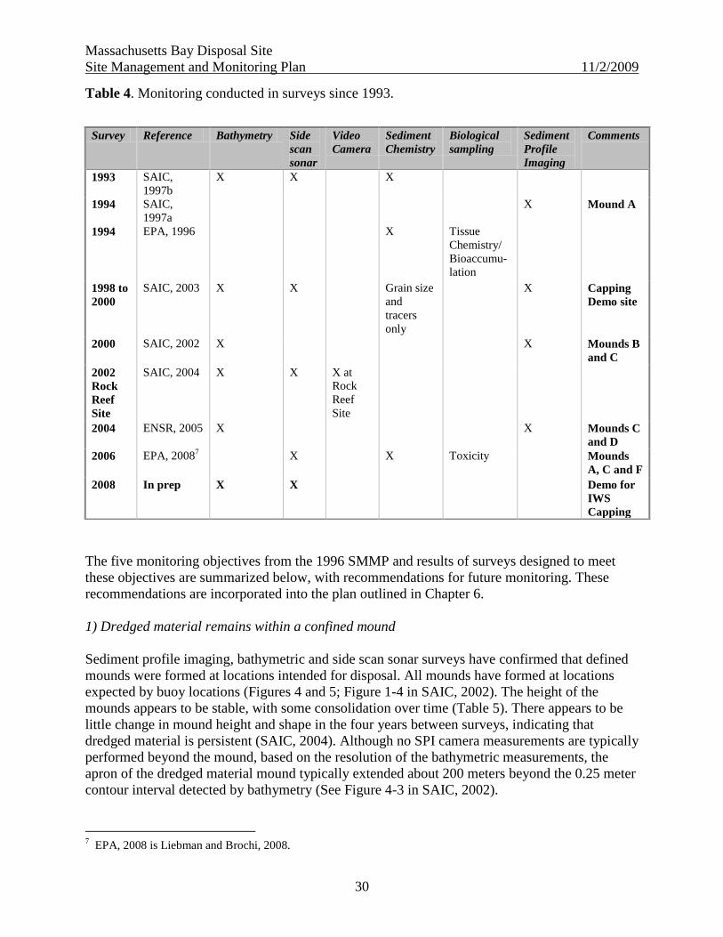
Massachusetts Bay Disposal Site
Site Management and Monitoring Plan 11/2/2009
30
Table 4. Monitoring conducted in surveys since 1993.
The five monitoring objectives from the 1996 SMMP and results of surveys designed to meet
these objectives are summarized below, with recommendations for future monitoring. These
recommendations are incorporated into the plan outlined in Chapter 6.
1) Dredged material remains within a confined mound
Sediment profile imaging, bathymetric and side scan sonar surveys have confirmed that defined
mounds were formed at locations intended for disposal. All mounds have formed at locations
expected by buoy locations (Figures 4 and 5; Figure 1-4 in SAIC, 2002). The height of the
mounds appears to be stable, with some consolidation over time (Table 5). There appears to be
little change in mound height and shape in the four years between surveys, indicating that
dredged material is persistent (SAIC, 2004). Although no SPI camera measurements are typically
performed beyond the mound, based on the resolution of the bathymetric measurements, the
apron of the dredged material mound typically extended about 200 meters beyond the 0.25 meter
contour interval detected by bathymetry (See Figure 4-3 in SAIC, 2002).
7 EPA, 2008 is Liebman and Brochi, 2008.
Survey Reference Bathymetry Side
scan
sonar
Video
Camera
Sediment
Chemistry
Biological
sampling
Sediment
Profile
Imaging
Comments
1993 SAIC,
1997b
X X X
1994 SAIC,
1997a
X Mound A
1994 EPA, 1996 X Tissue
Chemistry/
Bioaccumu-
lation
1998 to
2000
SAIC, 2003 X X Grain size
and
tracers
only
X Capping
Demo site
2000 SAIC, 2002 X X Mounds B
and C
2002
Rock
Reef
Site
SAIC, 2004 X X X at
Rock
Reef
Site
2004 ENSR, 2005 X X Mounds C
and D
2006 EPA, 20087 X X Toxicity Mounds
A, C and F
2008 In prep X X Demo for
IWS
Capping

Massachusetts Bay Disposal Site
Site Management and Monitoring Plan 11/2/2009
31
In addition, the Rock Reef Site was clearly formed at the intended location. Some material,
however, was deposited away from the intended location, but still within the disposal site
boundaries (Valentine et al., 1996).
Table 5. Approximate height (meters) of disposal mound above ambient area, or baseline
measurement, after last disposal event. Based on bathymetric measurements performed in 2000
and 2004 (SAIC, 2002; ENSR, 2005).
Mound Year of last
disposal event
Mound Width Mound Height (m)
Years after last disposal event
0 to 1 2 4 to 5 6 10
A 1994 400 to 500 meters 6 to 7 6 5
B 1998 350 to 500 meters -- 6 6
C 1999 600 to 750 meters 9 8
D 1999 250 to 300 meters 3.5 3
E 1999 250 to 300 meters 5 3
F 2005 450 4
2a) Benthic infauna recolonize disposal mounds
2b) The benthic community beyond the mound is not altered
Based on sediment profile imaging camera observations of mounds B, C and D taken in 2000
and 2004 benthic recolonization is occurring as expected (SAIC, 2002 and ENSR, 2005). At
Mound C one year after the last disposal event, dense populations of Stage I opportunistic
polychaetes were typically observed at the sediment surface. Stage III head down deposit-
feeding infauna were only observed at some outlying stations less influenced by the cohesive
Boston Blue Clay clumps. RPD depths were about 2 to 4 cm. SPI camera observations from
Mound C four years later in 2004 indicate little change in apparent RPD depths (values ranged
from 2 to 3.5 cm), but an increase in prevalence of Stage III infauna. It appears that the cohesive
Boston Blue Clay clumps are refractory to deeper colonization by Stage III infauna.
Five years after the last disposal event, Mound D appears to have fully recovered. Mean RPD
depths ranged from 3.5 to 4.9 cm, which is similar to reference sediments. There was no Boston
Blue Clay disposed at this mound. Both Stage I and Stage III communities were observed.
SPI camera observations were not collected from areas beyond the mounds in 2000 or 2004. SPI
camera measurements from reference areas, however, indicate normal (or expected) benthic
communities, with RPD depths of about 3 to 5 cm with Stage I and III communities and no
evidence of dredged material.
Massachusetts Bay Disposal Site
Site Management and Monitoring Plan 11/2/2009
32
3a) Contaminants are not accumulating in sediments at the disposal site and the reference areas
3b) Contaminants are not accumulating in biological resources beyond the mound
Based on a comparison to sediment quality guidelines (Field et al., 1999, 2002), levels of
contaminants collected from historically contaminated areas and recently disposed mounds do
not appear to be causing adverse impacts to the marine environment (see Section 4.1.3 and
Liebman and Brochi, 2008). In fact, sediments collected from the depression appear to be
declining for several individual PAHs and lead, although not for most other trace metals. At
Mound A, however, it appears that levels of chromium, copper, and some individual PAHs have
increased slightly since 1989, and there are no obvious decreases in sediment contamination
(Liebman and Brochi, 2008).
Dredged material at the disposal sites (Mounds A, C and F) and sediment at the reference areas
were not toxic to marine organisms, as measured by the Ampelisca abdita 10 day toxicity test.
This is consistent with the results of sediment contaminant levels, compared to sediment quality
guidelines.
No measurements of contaminants in bottom fish or lobsters from the MBDS or IWS have been
performed since 1992 (NOAA, 1996).
4) The benthic community at the old “BFG” buoy area is recovering from historical dredged
material disposal
The 2006 EPA survey found that many of the individual PAHs exhibited significant declines at
this site and no evidence of toxicity, but that most metals showed no significant downward trend
in contaminant levels (Liebman and Brochi, 2008).
5) The Rock Reef Site, and nearby rock debris, are colonized by a diverse hard rock epifaunal
and fish community
The Rock Reef site exhibits a relatively diverse community of colonizing sponges, anemones and
other epifauna (SAIC, 2004).
Massachusetts Bay Disposal Site
Site Management and Monitoring Plan 11/2/2009
33
6. QUANTITY AND QUALITY OF MATERIAL TO BE DISPOSED
MPRSA 102(c)(3)(D) and (E) requires that the SMMP include consideration of the quantity of
the material to be placed in the site, and the presence, nature, and bioavailability of the
contaminants in the material as well as the anticipated use of the site over the long term.
6.1 RECENT AND UPCOMING PROJECTS
The primary future use of the MBDS is from the Boston Harbor Inner Harbor Maintenance
Project and the proposed Deep Draft Navigation Improvement Project. The USACE began
dredging Boston Inner Harbor in April 2008 with completion in November 2008. About 900,000
cubic yards were disposed at Mound F and about 800,000 CY were disposed at a demonstration
site in the western part of the MBDS to evaluate whether dredged material can effectively isolate
historically disposed waste containers in the IWS. This material came from shoal material and
underlying parent material dredged to create CAD cells in the Mystic River and the main
shipping channel. Unsuitable material was disposed in the CAD cells (Michael Keegan, NAE
personal communication October 10, 2008; USACE/MassPort, 2006).
The U.S. Army USACE New England District in partnership with MassPort are also proposing a
project (Boston Harbor Federal Deep Draft Navigation Improvement Project) to deepen the main
channels in the Port of Boston, the Conley Container Terminal and other marine terminals to at
least -45 feet to -50 feet depth to accommodate the next generation of deep draft vessels
(USACE 2008). Based on the draft Feasibility Report (USACE/MassPort, 2008), the
recommended plan would result in about 1 million cubic yards of rock and 11.1 million cubic
yards of ordinary material, which has been determined to be suitable for ocean disposal in
Massachusetts Bay. If no upland use for this material is found, the rock and other hard material
are suitable for beneficial use to create hard bottom habitat. This project would likely be
constructed no earlier than 2012 and take about four years to complete.
NAE has suggested, and EPA has concurred, that some of this material be disposed at the old
IWS to cover up the containers and sediments exposed to contaminants from historic disposal at
the IWS. Disposal at the IWS, however, is outside of the current boundaries of the MBDS. To
dispose dredged material at the IWS areas would require a site selection process under the
MPRSA, or an expansion of the disposal site boundaries.
NAE is currently conducting a demonstration project in the western portion of the MBDS to
evaluate whether dredged material disposal in a sequential approach can cover up the containers,
without extensive impact to the in-place contaminated sediments, or barrel fragments. This
demonstration project is an integral component of the monitoring program.
Massachusetts Bay Disposal Site
Site Management and Monitoring Plan 11/2/2009
34
6.2 CAPACITY
Although Boston Harbor is the primary harbor expected to utilize the MBDS in the next decade,
other harbors are expected to utilize the site. Thus, for planning purposes, it is expected that the
MBDS will receive more dredged material in the next decade than in the previous decade. A
specific closure date for the MBDS has not been considered. Because of its depth (300 feet) and
size (2,662 acres), the potential capacity of the MBDS is far in excess of the potential site use
over the next 20 years, and does not pose a hazard to navigation.
6.3 DREDGED MATERIAL QUALITY: EVALUATION AND TESTING
REQUIREMENTS
As is the case for all EPA designated ocean disposal sites, the MBDS is designated to only
receive suitable dredged material. All dredged material projects proposed for disposal at the
MBDS must meet the ocean dumping criteria under the MPRSA and deemed suitable for
unconfined disposal. The projects will be evaluated on a project-specific basis under the rigorous
chemical and biological testing framework outlined in the Ocean Dumping Regulations (40 CFR
Parts 227 and 228) and guidance developed by EPA and the USACE (EPA/USACE, 1991; ―the
Green Book‖). This guidance is further implemented in New England under the EPA and
USACE Regional Implementation Manual (EPA and USACE, 20048). The RIM provides New
England-specific guidance on: permit application and coordination requirements; sampling
methodologies; updated reference site locations; contaminants of concern and analytical
reporting limits; and species and test conditions for biological testing.
The national guidance document is currently being updated by EPA and the USACE and the
final version is expected to be completed in 2010. Although this updated guidance will describe
modified approaches for interpretation of test results, it is unlikely that both the methods of
testing and the quality of dredged material acceptable for disposal will change significantly.
7. MANAGEMENT APPROACH
Dredged material disposal will be managed by the EPA and the USACE to meet the overall
objectives:
Management of disposal activities to ensure compliance with the MPRSA; and
Monitoring of the disposal site to determine whether significant adverse (or unacceptable)
impacts have occurred or are occurring.
8 The RIM is available at: http://www.nae.usace.army.mil/reg/rim.htm and
http://www.epa.gov/region1/topics/water/dredging.html

Massachusetts Bay Disposal Site
Site Management and Monitoring Plan 11/2/2009
35
To meet these objectives, the following specific management practices will be implemented:
All dredged material disposed at the MBDS must meet the ocean dumping criteria;
All general and specific permit conditions are implemented and enforced;
Disposal locations are specified to minimize environmental impact from sediments placed
at the site including establishing a containment cell of dredged material;
Disposal locations are also specified to avoid impact of sediments on identified cultural
resources (wrecks) in the site;
Disposal technologies are conducted to minimize loss of sediment from the disposal site;
Timing of disposal minimizes conflicts with other uses of the area;
Dredged material disposal information is recorded in an information management system;
Environmental and compliance monitoring is designed to recognize and correct conditions
before unacceptable impact occurs; and
Modifications to disposal practices and the site if necessary.
7.1 ALL DREDGED MATERIAL DISPOSED AT THE MBDS MUST MEET THE
OCEAN DUMPING CRITERIA
As described in Section 6.3, the MBDS is designated to only receive suitable dredged material.
All dredged material projects proposed for disposal at the MBDS must meet the ocean dumping
criteria under the MPRSA.
7.2 IMPLEMENTATION AND ENFORCEMENT OF ALL GENERAL AND SPECIFIC
PERMIT CONDITIONS
The following general conditions will be applied to all projects using the MBDS for disposal9.
These conditions may be modified on a project-by-project basis, based on factual changes (e.g.,
administrative changes in phone numbers, points of contact) or when deemed necessary as part
of the individual permit review process.
The following general permit conditions apply to all open water disposal in Massachusetts,
Maine, New Hampshire, Rhode Island and Vermont.
1. Periodic maintenance dredging to the area and depth limits described herein is
authorized for ten years from the date of issuance of this permit, provided disposal of the
dredged material is at an upland site. However, the permittee must notify this office, in
writing, 60 days before the intended date of any such dredging and shall not begin such dredging
until written authorization has been obtained. This 60-day notification is not required for the
initial new and/or maintenance dredging authorized by this permit. A separate authorization
9 These are the standard general conditions for dredging permits issued by NAE (Gregory Penta, Regulatory
Division, personal communication). Conditions related to protection of marine mammals are based on conservation
recommendations issued by NMFS in 1999 (Knowles, 1999) and modified by Julie Crocker, NMFS Northeast
Regional Office Protected Resources Division, 2009.
Massachusetts Bay Disposal Site
Site Management and Monitoring Plan 11/2/2009
36
shall be required for such dredging if the material to be dredged is to be deposited in open or
ocean waters and/or wetlands.
2. At least ten working days in advance of the start date, the First Coast Guard District,
Aids to Navigation Office, (617) 223-8355, shall be notified of the location and estimated
duration of the dredging and disposal operations.
3. For the initiation of disposal activity and any time disposal operations resume after
having ceased for one month or more, the permittee or the permittee’s representative must notify
the Corps (see Special Condition 7 below) at least ten working days before the date disposal
operations are expected to begin or resume. The information to be provided in this notification
is: permit number, permittee name, address and phone number, dredging contractor name,
address and phone number, towing contractor name, address and phone number, estimated dates
dredging is expected to begin and end, name of all disposal vessels to be employed in the work
and copies of their certification documents, name of the disposal site, and estimated volume of
material to be dredged. Disposal operations shall not begin or resume until the Corps issues
a letter authorizing the initiation or continuation of open-water disposal. The letter will
include disposal point coordinates to use for this specific project at that time. These coordinates
may differ from those specified for other projects using the same disposal site or even from those
specified earlier for this project. It is not necessary to wait ten days before starting disposal
operations. They may start as soon as this letter is issued. For each dredging season during
which work is performed, the permittee must notify the Corps upon completion of dredging for
the season by completing and submitting the form that the Corps will supply for this purpose
when disposal-point coordinates are specified.
4. Except when directed otherwise by the Corps for site management purposes, all
disposal of dredged material shall adhere to the following. These requirements must be followed
except when doing so will create unsafe conditions because of weather or sea state, in which case
disposal with the scow moving only fast enough to maintain safe control (generally less than one
knot) is permitted. Disposal is not permitted if these requirements cannot be met due to weather
or sea conditions. In that regard, special attention needs to be given to predicted conditions prior
to departing for the disposal site.
a. The permittee shall release the dredged material at a specified set of coordinates
within the disposal site with the scow at a complete halt.
b. When a disposal buoy is present at the specified coordinates, disposal shall
occur with the side of the scow at least 100 feet and no greater than 200 feet from the buoy to
minimize collisions with the buoy.
5. Silent Inspector System Requirements
a. Every discharge of dredged material at the disposal site requires monitoring by
the contractor. This disposal monitoring of dredging projects must be performed using the Silent
Inspector (SI) software and hardware system developed by the Corps. The SI system must have
been certified by the Corps within a year of the disposal activity. See the National SI Support
Center site https://si.usace.army.mil for additional SI information. Questions regarding
certification should be addressed to the SI Point of Contact at the Corps New England District
(Norm Farris, (978) 318-8336).
Massachusetts Bay Disposal Site
Site Management and Monitoring Plan 11/2/2009
37
b. The permittee is responsible for ensuring that the system is operational
throughout the project and that project data are submitted to the National SI Support Center in
accordance with the specifications provided at the aforementioned website. If any component of
the system is inoperable, disposal may not take place unless otherwise authorized by the Corps
New England District SI Point of Contact.
c. The SI system used by the permittee must be capable of providing the
information necessary for the Scow Monitoring Profile Specification. The permittee is also
responsible to provide the Corps (see Special Condition 7 below) with a record of estimated
barge volume for each trip. If barge volume information is not provided through the SI system
utilized, the permittee must submit a weekly report to Corps that provides estimated volume
(cubic yards), date and disposal time for each trip. The data collected by the SI system shall,
upon request, be made available to the Corps (see Special Condition 7 below).
d. For the initiation of disposal activity and any time disposal operations resume
after having ceased for one month or more, the permittee or the permittee’s representative must
notify the Corps (see Special Condition 7 below) at least ten working days before the date
disposal operations are expected to begin or resume. The information to be provided in this
notification is: permit number, permittee name, address and phone number, phone number of the
dredging contractor, name, address and phone number of towing contractor, estimated dates
dredging is expected to begin and end, name of all disposal vessels to be employed in the work
and copies of their certification documents, name of the disposal site, and estimated volume of
material to be dredged. Disposal operations shall not begin or resume until the Corps issues
a letter authorizing the initiation or continuation of open-water disposal. The letter will
include disposal point coordinates to use for this specific project at that time. These coordinates
may differ from those specified for other projects using the same disposal site or even from those
specified earlier for this project. It is not necessary to wait ten days before starting disposal
operations. They may start as soon as this letter is issued.
6. If any material is released beyond the limits specified in this permit, the Captain or
the permittee must notify the Corps immediately by phone (see Special Condition 7 below).
Information provided shall include disposal coordinates, permit number, volume disposed, date
and time of disposal, circumstances of incident, disposal vessel name, name of caller, and phone
number of caller. If no person is reached at the number above, a voice message with the relevant
information should be provided. In addition, a detailed written report must be provided to the
Corps within 48 hours following any such incident.
7. Unless otherwise stated (e.g., as in Special Condition 5b above), all submittals and
coordination related to these special conditions shall go to the Corps, New England District.
ADDRESS: Policy, Analysis and Technical Support Branch, Regulatory Division, U.S. Army
Corps of Engineers, 696 Virginia Road, Concord, MA 01742-2751; Phone: (978) 318-8292 or
(978) 318-8338; Fax: (978) 318-8303.
The following additional permit conditions apply specifically to MBDS disposal permits.
1. The U.S. Coast Guard, Sector Boston, Waterways Management Division, (617) 223-
5750, shall be notified prior to the start of this project.
Massachusetts Bay Disposal Site
Site Management and Monitoring Plan 11/2/2009
38
2. From February 1 through May 30 of any year, disposal vessels including tugs, barges,
and scows transiting between the dredge site and the Massachusetts Bay Disposal Site shall
operate at speeds not to exceed 5 knots after sunset, before sunrise, or in daylight conditions
where visibility is less than one nautical mile. Disposal shall not be permitted if these
requirements cannot be met due to weather or sea conditions. In that regard, the permittee and
contractor should be aware of predicted conditions before departing for the disposal site. The
intent of this condition is to reduce the potential for vessel collisions with endangered species,
including right whales.
3. From February 1 through May 30 of any year, a marine mammal observer [i.e.
meeting the attached National Marine Fisheries Service (NMFS) criteria on observer
qualifications, including the specified skill sets for sea turtles and whales, and in receipt of
written approval from NMFS] must be present aboard disposal vessels transiting between the
dredge site and the Massachusetts Bay Disposal Site during daylight hours. The permittee shall
submit to the Corps of Engineers for approval a statement of qualifications for each observer.
The observer(s) shall be contracted and paid for by the permittee.
4. When threatened or endangered species are observed to be present, the vessel captain
shall, except when precluded by safety considerations, avoid harassment of or direct impact to
individual animals in consultation with the marine mammal observer.
5. The permittee (or designee) shall report any interactions with listed species to NMFS
within 24-hours at (978) 281-9328 and immediately report any injured or dead marine mammals
or sea turtles to NMFS Stranding Hotline at (978) 281-9351.
6. The permittee shall ensure that a separate NMFS Marine Mammal Observation
Report is fully completed by the observer for every sighting and that this report is received by
the Corps, (978) 318-8303 fax, within one week of the trip date. The permittee shall require the
observer to maintain contact with NMFS, Habitat and Protected Resources Division, (978) 281-
9328 and other recognized experts to provide and receive information regarding the presence and
distribution of threatened and endangered species in Massachusetts Bay. The intent of this
condition is to reduce the potential for vessel collisions with threatened and endangered species,
including right whales, and to minimize potential impacts of dredged material disposal on
threatened and endangered species.
7. Marine mammal observers shall use the following guidelines to minimize conflicts
with threatened or endangered species:
a. A marine mammal observer shall be posted on lookout at all times during
daylight hours when disposal vessels have left the harbor and are traveling to, at or returning
from the disposal site.
b. Disposal vessels shall not approach threatened or endangered species closer
than 100 feet (see additional condition below for approaching right whales).
c. Disposal vessels shall adhere to the attached NMFS regulations for approaching
right whales, 50 CFR Part 222.32, which restrict approaches within 500 yards of a right whale
and specify avoidance measures for vessels that encounter right whales.

Massachusetts Bay Disposal Site
Site Management and Monitoring Plan 11/2/2009
39
d. If threatened or endangered species are sighted within 500 feet from the
disposal point, dredged material shall not be released. In this case, the vessel captain may elect
to wait until the animals move away from the disposal point prior to disposal, or subject to
consultation with the observer, may dispose at a Corps-authorized alternative disposal location
under the same restrictions noted herein for disposal at the primary disposal location.
e. If threatened or endangered species are sighted between 500 feet and 1500 feet
from the disposal point, the observer shall note the animals' behavior, relative position, and
direction and speed of movement to assess if release of dredged material is likely to harass or
endanger the animals. For example, whales actively feeding at or near the disposal point are
more likely than resting whales to interact with released sediments. If the observer assesses that
disposal is likely to harass or endanger the animals, the observer shall consult with the vessel
captain and disposal shall be delayed until the animals change their behavior or move away such
that the observer assesses that no danger to the animals will likely result from disposal.
Other special management practices may exist at the site for individual projects to improve site
management, anticipate future disposal requirements, or improve the conditions at the site.
7.3 DISPOSAL LOCATIONS AND COORDINATES
The USACE deploys a taut wire buoy at the specific coordinates for the disposal location. If a
buoy is not available, specified coordinates are provided to the permittee. Disposal locations are
specified to minimize environmental and cultural resource impacts from sediments placed at the
site. The MBDS is currently being managed to develop a containment cell around which dredged
material is disposed in a ring of mounds. The containment cell is located in a natural depression
near the northeast quadrant of the disposal site. The depression is expected to accumulate
contaminants from the disposal mound, and from natural sediment deposition in Stellwagen
Basin10
. It is expected that this depression will eventually be contained with additional dredged
material.
In 2008, coordinates were provided for disposal in the western portion of the MBDS to evaluate
whether dredged material disposal in a sequential approach can cover up the containers, without
an unacceptable disturbance of in-place contaminated sediments, or barrel fragments (See
Section 6.3). This demonstration project is an integral component of the monitoring program.
7.4 ALLOWABLE DISPOSAL TECHNOLOGIES AND METHODS
Dredging and dredged material disposal in Massachusetts Bay has historically been
accomplished using a bucket dredge to fill split hull or pocket scows for transport to the disposal
site. Typically, 1,000 to 6,000 CY vessels are used for disposal. The volume of material allowed
10
Unsuitable dredged material cannot be disposed at MBDS.
Massachusetts Bay Disposal Site
Site Management and Monitoring Plan 11/2/2009
40
in a barge may be restricted depending upon the results of the USACE water quality model11
used during evaluation of dredged material for any given dredging project (see Section 6.3).
7.5 TIMING OF DISPOSAL MINIMIZES CONFLICTS WITH OTHER USES OF THE
AREA
At this time, there are no seasonal restrictions on disposal of dredged material at the site. After
consultation with NMFS and MA DMF time of year (TOY) windows are typically established,
however, to protect sensitive fish species at the dredge site. As described in Section 4, a LNG
port has been constructed (NEG) adjacent to the disposal site and another port (Neptune) is
currently under construction. Although the presence of a LNG tanker in the area may require
occasional changes in transport routes to the MBDS there are no restrictions on disposal when an
LNG tanker is on station at either of the offshore terminals.
7.6 DREDGED MATERIAL DISPOSAL COMPLIANCE INFORMATION IS
RECORDED IN AN INFORMATION MANAGEMENT SYSTEM
See Section 8.1.
7.7 ENVIRONMENTAL AND COMPLIANCE MONITORING ARE DESIGNED TO
RECOGNIZE AND CORRECT CONDITIONS BEFORE UNACCEPTABLE
(SIGNIFICANT ADVERSE) IMPACT OCCURS
See Sections 8.1 and 8. 2.
7.8 MODIFICATIONS TO DISPOSAL PRACTICES AND THE SITE
Based on the findings of the monitoring program, no modifications to the site use are
contemplated. Corrective measures such as those listed below, however, may be developed by
EPA New England and the USACE-NAE if necessary. These measures may include:
Stricter definition and enforcement of disposal permit conditions;
Implementation of more protective judgments on whether sediments proposed for
dredging are suitable for open-water disposal;
Implementation of special management practices to prevent any additional loss of
sediments to the surrounding area;
Closure of the site as an available dredged material disposal site (i.e., to prevent any
additional disposal at the site).
11
NAE evaluates all disposal projects with potential to violate water quality standards at the MBDS using the
STFATE model, which is described in the RIM and is available at:
http://el.erdc.usace.army.mil/products.cfm?Topic=model&Type=drgmat
Massachusetts Bay Disposal Site
Site Management and Monitoring Plan 11/2/2009
41
In addition, other management considerations may be determined on a project-by-project basis
through consultation with the NMFS, USFWS and MA DMF, and coordination with other state
and Federal agencies. These may include the following:
Use of marine mammal observers during disposal operations outside of the February 1 to
May 30 time period;
Establishment of dredging windows;
Compliance with Essential Fish Habitat (EFH) recommendations; and
Endangered Species Act (ESA) concerns.
Any changes to special permit conditions may be discussed at the Regional Dredging Team or
Massachusetts Dredging Team meetings.
As described in Section 6.1 some of the future Boston Harbor dredged material is proposed for
disposal at the old IWS. Disposal at the IWS, however, is outside of the current boundaries of the
MBDS and would necessitate an expansion (perhaps temporary) of the disposal site boundaries
or a specific time-limited site selection.
8. MONITORING PROGRAM
The monitoring program is organized into two complementary parts: compliance monitoring and
environmental monitoring.
8.1 COMPLIANCE MONITORING
Compliance monitoring includes evaluation of information and data relevant to the conditions in
permits and authorizations and will be gathered separately from the environmental data. Disposal
operations will be routinely reviewed to determine whether the requirements of the issued
permits and authorizations have been met. This includes review of the Silent Inspector logs, and
any observations by the USACE project managers on a project-specific basis to determine the
potential magnitude of effect and the appropriate action.
All dredged material disposal compliance information is recorded in an electronic database
called Dredged Material Spatial Management and Resolution Tool [DMSMART]). DMSMART
is designed to incorporate results from the dredged material sediment analyses and scow logs.
DMSMART includes the following fields for each disposal record: permit number, disposal load
volume, and disposal location. The database assists the USACE to evaluate projects from the
same or nearby areas, and compliance with conditions in disposal permits and authorizations.
It is assumed that testing information from projects authorized to use the site for dredged
material disposal and from the reference area can provide key information about the expected
quality of material that has been placed in the site.
Massachusetts Bay Disposal Site
Site Management and Monitoring Plan 11/2/2009
42
8.2 ENVIRONMENTAL MONITORING OBJECTIVES
As described in Section 5.2, the monitoring program is prospective, in that it attempts to identify
early warning indicators of adverse effects, as described in the conceptual model, and is based on
hypothesis testing using sampling technologies with rapid data return. The monitoring described
below is typically Tier 1 monitoring in the Tiered Monitoring Protocol recommended by
Germano et al. (1994) and generally followed by the DAMOS program for many years. If results
of the first tier hypothesis indicate an adverse effect or unacceptable impact, then a second tier
monitoring test is triggered.
The timing of monitoring surveys and other activities will be governed by funding resources, the
frequency of disposal at the site, and the results of previous monitoring data. Measurement of
certain conditions in the site can be performed at a lower frequency (e.g., sediment chemistry) or
only in response to major environmental disturbances such as the passage of major storms.
The specific objectives of the monitoring plan proposed here are slightly modified from the
original objectives in 1996 and incorporate the demonstration project to evaluate in-place
sediment capping and continuation of the development of a containment cell and the potential
continued disturbance by operation of the nearby LNG ports. In addition, we added another
objective to evaluate the suitability of the reference area. These objectives are posed as testable
hypotheses.
1) Dredged material remains within a confined mound
Tier 1 monitoring: This will be accomplished by periodic high resolution multibeam bathymetry,
side scan sonar or sediment acoustic characterization, supplemented with sediment profile
imaging. SPI measurements will be collected from transects radially away from the disposal
mound up to 1,000 meters from the center. Because mounds are being formed at distinct
locations in the disposal site to create a containment cell, it is recommended that these surveys be
conducted about six months to one year after the end of disposal at each mound, and a follow-up
three to five years later.
Response: A confined mound is defined as a mound located at the disposal buoy with no
significant change in height or shape. Mounds are expected to consolidate (lose height) over
time, but to not change shape significantly. Changes in height and shape can be detected by
comparison of bathymetric observations from previous surveys, within the resolution of the
equipment. Height and diameter of newly formed mounds can be estimated based on the volume
of material disposed. If these measurements indicate that a disposal mound is confined within an
expected area, no management action is required. If these measurements indicate that a disposal
mound is not confined within an expected area, a review of disposal permits and silent inspector
records will be conducted. Additional SPI camera measurements will be performed to determine
the magnitude and spatial extent of movement of material.
Massachusetts Bay Disposal Site
Site Management and Monitoring Plan 11/2/2009
43
2a) Benthic infauna recolonize disposal mounds
2b) The benthic community beyond the mound is not adversely impacted
Tier 1 monitoring: This will be accomplished by sediment profile imaging performed six months
to about one year after the cessation of mound formation, and a follow up three to five years
later. SPI camera measurements should be conducted to the edge of each mound to ensure that
biological observations are consistent with the bathymetric surveys. Samples will be collected
routinely from recently formed mounds; transects radially away from the disposal mound up to
1,000 meters from the center, and randomly selected stations from the disposal mound and the
MBDS reference area. Sampling using radial transects are employed to measure a gradient of
impact from disposal mounds. Following completion of disposal, a SPI camera survey should be
performed over the new Mounds E and F and the demonstration mounds to confirm that the
expected pattern of benthic recolonization is occurring. Evaluation of recolonization and adverse
impacts will be made based on statistical evaluation of the parameters measured by SPI cameras.
Response: If the results of these tests indicate that recolonization on the disposal mounds is
occurring, no management action is required. If the results of these tests indicate that
recolonization is not occurring, then SPI camera measurements from off the disposal mound will
be examined to determine whether this biological response is widespread or is not related to
disposal. If SPI camera measurements determine that Stage III fauna are absent away from the
disposal mounds after three to five years, the SPI camera photographs should be evaluated to
determine whether grain size or other sediment properties may be hindering recolonization or the
expected succession sequence. If neither of these hypotheses explains the pattern observed,
sediment toxicity tests should be conducted as soon as feasible.
3a) Contaminants are not accumulating in sediments at the disposal site and the reference areas
Tier 1 monitoring: Sediments should be collected and measured for contaminants once every
five to ten years, or whenever benthic community appears to be altered based on results of
sediment profile imaging. Samples will be collected from recently formed mounds at randomly
selected stations on the mounds and at the MBDS reference area, but may include stations with
historical SPI observations. Statistical approaches to compare mounds to reference areas are
described in Section 5. Levels of contaminants in disposal site sediments will be compared to
reference area sediments and to previously measured disposal site sediment contaminant levels.
Response: If levels of many (e.g. >5) contaminants are not significantly greater than (as
determined by an ANOVA or non-parametric test) recently disposed sediments, reference
sediments, unimpacted sites within the disposal site, or previous measurements in the same area,
then no management action is required. If levels of many contaminants are significantly greater
than recently disposed sediments, then results of dredged material suitability determinations
should be re-examined for possible explanations. If statistically significant increases in sediment
chemistry above permitted dredged material project data are found, then theoretical
bioaccumulation potential (TBP) calculations will be performed. If TBP calculations suggest
significant potential for bioaccumulation, direct bioaccumulation tests should be performed (see
hypothesis 3b).
Massachusetts Bay Disposal Site
Site Management and Monitoring Plan 11/2/2009
44
3b) Contaminants are not accumulating in biological resources beyond the mound
Tier 2 monitoring: Based on the sediment chemistry monitoring and application of the
theoretical bioaccumulation potential model (using highest replicates), levels of contaminants in
fish can be predicted.
Response: If the bioaccumulation model results in concentrations above acceptable levels for
ecological and human health, sampling of tissue from resident species such as the ocean quahog,
lobster and American plaice (and if feasible, the Acadian redfish) should be conducted. To relate
contaminant levels to biological effects a baseline study of histopathology of American plaice, or
the dominant benthic fish or shellfish, may be considered.
4) The benthic community at the old “BFG” buoy area is recovering from historical dredged
material disposal
Tier 1 monitoring: This should be accomplished by periodic sediment profile imaging, bottom
grabs with benthic community analysis, and toxicity testing at the old ―BFG‖ buoy area
conducted with transects radially up to 1,000 meters away from the center of the area. Sampling
using radial transects are employed to measure a gradient of impact from the former disposal
area. Because SPI camera measurements have not been conducted at this site since 1994, it is
recommended that SPI camera measurements be performed at this site if funding is available.
Results of these surveys will assist in verifying assumptions of the conceptual model of benthic
impacts of dredged material disposal. The EPA survey in 2006 demonstrated elevated, but
moderate levels of contaminants at this site, and that the sediments were not toxic to amphipods.
Response: If the measurements indicate an unexpected benthic community based on our
understanding of impacts of dredged material disposal to the biological community (see section
4) then sampling of tissue from resident species such as the ocean quahog, lobster and American
plaice (and if feasible, the Acadian redfish) should be conducted to determine the extent of the
effects. If ecological and potential human health effects are observed, further capping of these
sediments should be contemplated12
.
5) The Rock Reef Site, and nearby rock debris, are colonized by a diverse hard rock epifaunal
and fish community
Tier 1 monitoring: Although this site appears to exhibit a relatively unaltered community of
colonizing sponges, anemones and other epifauna periodic (e.g. every five to ten years) video
observations of the benthic community should be conducted. This should be performed in
association with the Stellwagen Bank National Marine Sanctuary program.
Response: if video observations indicate an altered or unexpected benthic community, a more
intense research and monitoring effort should be contemplated to determine the potential cause.
The expected benthic community will be based on observations from other areas in Stellwagen
Bank.
12
Based on the EPA survey results in 2006 (Liebman and Brochi, 2008), this action is not likely.
Massachusetts Bay Disposal Site
Site Management and Monitoring Plan 11/2/2009
45
6) Evaluation of re-suspension of bottom sediments from disposal of dredged material
Special study: At the time this plan was under revision, NAE was conducting a demonstration
project in the western portion of the MBDS to evaluate whether dredged material disposal in a
sequential approach can cover up the historically disposed waste containers, without
unacceptably impacting the in-place sediments or barrel fragments. This study was investigating
the feasibility of using the large volume of sediments that will be available when Boston Harbor
is deepened in the coming years (see Section 6.1) to cap portions of Massachusetts Bay that
received industrial wastes from the 1940s to 1970s (see Section 3.2). The sediments used in the
study were from creation of confined aquatic disposal cells in the harbor; sediments similar to
those expected from the deepening. Barge loads of the sediment were directed to a series of
placement lines and points in a simulation of capping. The investigation focused on methods to
minimize disposal impacts on the in-place sediments. Surveys were being conducted to map the
distribution of the disposed sediment and assess its disturbance of the in-place sediments.
Survey tools included high resolution bathymetry, sediment profile and plan view camera
photographs, side scan sonar, sub-bottom profiling, and sediment coring.
Response: If results of this study suggest that in-place sediments were not significantly disturbed,
this approach would be utilized to cap the containers.
7) Evaluation of suitability of reference area
Mapping the location of the reference area onto a base map of the topography of Massachusetts
Bay prepared by the USGS (Butman et al., 2004) indicated that the reference area may be
located on and around a drumlin. The drumlin is a topographic high and may influence grain size
and other sediment properties. In comparing sediment collected from the reference area in 2006
to previous years Liebman and Brochi (2008) identified significant variability in grain size and
TOC content of the sediments from the reference area. A review of reference area data will be
conducted and a survey will be performed to better map the seafloor in the area and determine
whether a more suitable reference area can be selected to reduce this variability.
8.3 EVALUATION OF DATA AND MANAGEMENT RESPONSES
The identification of unacceptable impacts from dredged material disposal at the site will be
accomplished in part through comparisons of the monitoring results to historical (baseline) and
previous conditions, and to unimpacted nearby reference locations measured concurrently with
site measurements. If site monitoring data demonstrates that the disposal activities are causing
unacceptable impacts to the marine environment as defined under 40 CFR §228.10(b), EPA and
the USACE may place appropriate limitations on site usage to reduce the impacts to acceptable
levels. Such responses may include: limitations on the amounts and types of dredged material
permitted to be disposed; limitations on the specific disposal methods, locations, or timing;
isolation of sediments with elevated contaminants or de-designating the site for unconfined
ocean disposal of dredged material.
Massachusetts Bay Disposal Site
Site Management and Monitoring Plan 11/2/2009
46
8.4 MONITORING TECHNOLOGIES AND TECHNIQUES
The technologies used for this monitoring plan have already been described in Section 5; these
technologies and approaches are typically used to evaluate dredged material disposal sites in the
northeast United States. Use of consistent techniques increases comparability with future and
historic data; monitoring methods used at the MBDS, however, are not limited to these
technologies. New technology and approaches may be used as appropriate to address questions
that arise in the future. For example, 40 CFR §228.9(b) states that surveys may be supplemented,
―where feasible and useful, by data collected from the use of automatic sampling buoys, satellites
or in situ platforms, and from experimental programs.‖
8.5 QUALITY ASSURANCE
An important part of any monitoring program is a quality assurance (QA) regime to ensure that
the monitoring data are reliable. Quality assurance has been described as consisting of
two elements:
1. Quality Control - activities taken to ensure that the data collected are of adequate quality
given the study objectives and the specific hypothesis to be tested, and include
standardized sample collection and processing protocols and technician training (National
Research Council [NRC], 1990).
2. Quality Assessment - activities implemented to quantify the effectiveness of the quality
control procedures, and include repetitive measurements, interchange of technicians and
equipment, use of independent methods to verify findings, exchange of samples among
laboratories and use of standard reference materials, among others (NRC, 1990).
All EPA organizations that collect, evaluate, or use environmental data or design, construct, or
operate environmental technology are covered by the EPA Quality System. Data collected by
EPA must meet the requirements in the EPA Directive CIO 2105-P-01-0 (Quality Manual for
Environmental Programs) and develop an approved Quality Assurance Project Plan13
. All
USACE monitoring must meet QA requirements as specified in contract award documents. This
usually involves the contractor providing a QA plan for the various types of work requested.
8.6 COORDINATION WITH COMPLEMENTARY OR REGIONAL MONITORING
PROGRAMS
The regulation 40 CFR §228.10(c) requires that a disposal site be periodically assessed based on
the entire available body of pertinent data and that any identified impacts be categorized
according to the overall condition of the environment of the disposal site and adjacent areas.
Some aspects of the impact evaluation required under MPRSA §102(c)(3) can be accomplished
using data from regional monitoring programs (e.g., fisheries impact).
13
EPA QA guidance documents are found at <http://www.epa.gov/quality/qs-docs/g5-final.pdf>.
Massachusetts Bay Disposal Site
Site Management and Monitoring Plan 11/2/2009
47
Thus, EPA and the USACE will review ongoing regional monitoring programs that can provide
additional data to inform the periodic assessment of impact, such as the MWRA outfall
monitoring program, the Stellwagen Bank National Marine Sanctuary programs, NMFS or MA
DMF trawl surveys for fisheries resources (See Section 3 Baseline Assessment), and monitoring
associated with the LNG ports.
9. REVIEW AND REVISION OF THIS PLAN
The MPRSA requires that the SMMP include a schedule for review and revision of the SMMP,
which shall not be reviewed and revised less frequently than ten years after adoption of the plan,
and every ten years thereafter. The next revision of this SMMP will be completed by 2019. The
EPA, the USACE, and other federal and state agencies have agreed to review this plan yearly as
part of the annual agency planning meeting agenda (Section 3.2). Reassessment of the EFH and
endangered species issues will also be conducted on a ten year basis with NMFS.
10. COORDINATION AND OUTREACH
The EPA and the USACE coordinate closely on management of the disposal site, and evaluation
of permit applications for disposal of dredged material disposal. The EPA and the USACE also
coordinate closely with the Massachusetts and Regional Dredging teams. Coordination and
outreach will be continuous and include state and Federal agencies, scientific experts, and the
public. These teams may provide recommendations on management of the MBDS. Other
meetings may be called in response to unusual physical events or unexpected monitoring
observations. During these meetings, monitoring data will be evaluated and the SMMP will be
revised as necessary depending on current conditions and available site-specific and scientific
information.
To ensure communications are appropriate and timely, site management activities and
monitoring findings will be communicated through many mechanisms: scientific reports, peer
reviewed publications, participation in symposia, the USACE and EPA websites, public
meetings, and fact sheets. For example, the DAMOS Program holds periodic symposia (typically
every three years) to report results and seek comments on the program. In addition, DAMOS
monitoring results are published in an ongoing series of technical reports that are mailed to
interested parties and organizations, are distributed at various public meetings, and published on
the DAMOS website14
. The USACE also has prepared and distributed several Information
Bulletins and brochures on different aspects of the dredged material management. Site-related
reports can also be reviewed at both the USACE Technical Library and the EPA regional
libraries:
U.S. EPA New England U.S. Army Corps of Engineers
14
http://www.nae.usace.army.mil/damos/index.asp
Massachusetts Bay Disposal Site
Site Management and Monitoring Plan 11/2/2009
48
Regional Library NAE Technical Library
John W. McCormack Federal Bldg 696 Virginia Road
Five Post Office Square
Boston, MA 02109 Concord, MA 01742-2751
Hours: Monday-Thursday 9:30 to 3:30 pm Hours: Monday-Friday 7:30-4:00
Tel: 617-918-1990 Tel: 978-318-8118
http://www.epa.gov/libraries/region1.html
Any party interested in being added to the DAMOS mailing list should provide their contact
information to the USACE at:
U.S. Army Corps of Engineers, New England District
Regulatory Division
Marine Analysis Section
696 Virginia Road
Concord, MA 01742-2751
11. FUNDING
The costs involved in site management and monitoring will be shared between EPA New
England and USACE-NAE and are subject to the availability of funds. This SMMP will be in
place until modified or the site is de-designated and closed.
These recommendations do not necessarily reflect program and budgeting priorities of the
Federal government in the formulation of EPA's national Water Quality program or the USACE
national Civil Works water resources program. Consequently, any recommendations for specific
activities or annual programs in support of efforts in the waters of coastal Massachusetts may be
modified at higher levels within the Executive Branch before they are used to support funding
level recommendations. Requests for funding are also subject to review and modification by
Congress in its deliberations on the Federal budget and appropriations for individual programs.
Similarly, state agency programs will depend solely on funds allocated to the programs by those
agencies or other supporting agencies.
12. REFERENCES
Bothner, M.H. and B. Butman (eds.). 2005. Processes influencing the transport and fate of
contaminated sediments in the coastal ocean—Boston Harbor and Massachusetts Bay: U.S.
Geological Survey Open-File Report 2005-1250. Created October 17, 2005.
Bothner, M.H. and B. Butman (eds.). 2007. Processes influencing the transport and fate of
contaminated sediments in the coastal ocean—Boston Harbor and Massachusetts Bay: U.S.
Geological Survey Circular 1302, 89 pp. (Available online at
http://pubs.usgs.gov/circ/2007/1302/.)

Massachusetts Bay Disposal Site
Site Management and Monitoring Plan 11/2/2009
49
Butman, B., M.H. Bothner, J.C. Hathaway, J.L. Jenter, H.J. Knebel, F.T. Manheim, and R.P.
Signell. 1992. Contaminant transport and accumulation in Massachusetts Bay and Boston
Harbor: a summary of U.S. Geological Survey studies. USGS Open File report 92-202. Woods
Hole, MA.
Butman, B. and J.A. Lindsay (eds). 1999. A Marine GIS Library for Massachusetts
Bay: Focusing on Disposal Sites, Contaminated Sediments, and Sea Floor Mapping. U.S.
Geological Survey Open-File Report 99-439. October 1999. U.S. Geological Survey, Woods
Hole, MA and NOAA Office of Response and Restoration, Seattle, WA.
Butman, B., P. C. Valentine, W. W. Danforth, L.Hayes, L. A. Serrett, and T. J. Middleton. 2004.
Shaded Relief, Sea Floor Topography, and Backscatter Intensity of Massachusetts Bay and the
Stellwagen Bank Region Offshore of Boston, Massachusetts. U.S. Geological Survey Geologic
Investigations Series Map I-2734. Version 1.0. Prepared in cooperation with the National
Oceanic and Atmospheric Administration. (Available online at
http://pubs.usgs.gov/imap/i2734/).
Butman, B., P. C. Valentine, T. J. Middleton, and W. W. Danforth. 2007. A GIS Library of
Multibeam Data for Massachusetts Bay and the Stellwagen Bank National Marine Sanctuary,
Offshore of Boston, Massachusetts. U.S. Geological Survey Data Series 99, Version 1.0.
(Available online at http://woodshole.er.usgs.gov/pubs/ds-99/).
ENSR. 2005. Monitoring Survey at the Massachusetts Bay Disposal Site, September 2004.
DAMOS Contribution No. 162. U.S. Army Corps of Engineers, New England District, Concord,
MA, 64 pp.
ENSR. 2007. Monitoring Survey at Boston Harbor CAD Cells, August 2004. DAMOS
Contribution No. 168. U.S. Army Corps of Engineers, New England District, Concord, MA, 112
pp.
Field, L.J., D.D. MacDonald, S.B. Norton, C.G, Severn, and C.C. Ingersoll. 1999. Evaluating
sediment chemistry and toxicity data using logistic regression modeling. Environmental
Toxicology and Chemistry 18(6):1311-1322.
Field, L.J., D.D. MacDonald, S.B. Norton, C.G, Severn, C.C. Ingersoll, D. Smorong, and R.
Linkskoog. 2002. Predicting amphipod toxicity from sediment chemistry using logistic
regression models. Environmental Toxicology and Chemistry 21(9):1993-2005.
Germano, J.D., D.C. Rhoads, and J.D. Lunz. 1994. An integrated, tiered approach to monitoring
and management of dredged material disposal sites in the New England region. DAMOS
Contribution No. 87. May 1994. U.S. Army Corps of Engineers, New England Division.
Waltham, MA. 81 pp.
Massachusetts Bay Disposal Site
Site Management and Monitoring Plan 11/2/2009
50
Hubbard, W.A., J.M. Penko, and T.S. Fleming. 1988. Site Evaluation studies of the
Massachusetts Bay Disposal Site for Ocean Disposal of Dredged Material. U.S. Army Corps of
Engineers New England Division.
Hunt C.D., M. Hall, S. Pala, and D.T. Dahlen. 2006. A Review and Summary of Toxic
Contaminants in Boston Harbor and Massachusetts Bay: 1990 to 2005. Boston: Massachusetts
Water Resources Authority. Report ENQUAD 2006-23. 136pp.
Keith, D., J. Schoenherr, J. Cook, D. Carey, and G. Tracey. 1992. U.S. Environmental
Protection Agency. Final cruise report: Location survey and condition inspection of waste
containers at the Boston Lightship dumping ground and surrounding area. ERL-N Contribution
No. 1405. US EPA Environmental Research Laboratory-Narragansett. Narragansett, RI. 76 pp.
King, J., M. Camisa, V. Manfredi and S. Correia. 2007. MA DMF 2007 Annual Performance
Report, Project Title: Massachusetts Fishery Resource Assessment. Available online at
http://www.mass.gov/dfwele/dmf/programsandprojects/f56r15_resource_2007_web1.pdf
Knowles, D. 1999. Letter from Donald Knowles, Director of Office of Protected Resources,
National Marine Fisheries Service, to John DeVillars, EPA Region 1 Regional Administrator.
Amendment to 1991 Biological Opinion on the MBDS Designation. October 18, 1999.
Libby, P.S., W.R. Geyer, A.A. Keller, A.D. Mansfield, J.T. Turner, D. Borkman and C.A. Oviatt.
2006. 2004 Annual Water Column Monitoring Report. Boston: Massachusetts Water
Resources Authority. Report ENQUAD 2006-15. 177p.
Liebman, M. and J. Brochi. 2008. US EPA Survey at the Massachusetts Bay Disposal Site and
Industrial Waste Site July 2006. U.S. EPA Region 1 (New England) Office of Ecosystem
Protection, Ocean and Coastal Protection Unit. Draft Report. September 11, 2008. Boston, MA.
55 pp.
Massachusetts Office of Coastal Zone Management (MA CZM). 2000. Dredged Material
Management Plan (DMMP) EOEA No. 11534. Draft Environmental Impact Report (DEIR) for
Gloucester, Massachusetts. Prepared by Maguire Group Inc., Foxborough, Massachusetts.
Prepared for Massachusetts Office of Coastal Zone Management. Boston, Massachusetts.
(Available online at http://www.mass.gov/czm/gloudmmp.htm).
Massport, 2008. Web site accessed September 16, 2008.
http://www.massport.com/ports/about_ports.html
Moore, M.J., R. Smolowitz, K. Uhlinger, L. Lefkovitz, J. Ziskowski, G. Sennefelder, J. King, M.
Hall, J. Schwartz and D. Pierce. 2005. Ulcerative Dermatitis in Massachusetts Bay Winter
Flounder, Pseudopleuronectes americanus. Presentation to the MWRA Outfall Monitoring
Science Advisory Panel Flounder Focus Group, March 31, 2005. (Available online at
http://www.epa.gov/region1/omsap/omsapm.html.)
Massachusetts Bay Disposal Site
Site Management and Monitoring Plan 11/2/2009
51
National Research Council (NRC), 1990. Managing troubled waters, the role of marine
environmental monitoring. National Academy Press. 95 pp.
National Oceanic and Atmospheric Administration (NOAA). 1996. The Massachusetts Bay
Industrial Waste Site: A Preliminary Survey of Hazardous Waste Containers and an Assessment
of Seafood Safety. (May and June 1992). NOAA Technical Memorandum NOS ORCA 99.
Edited by John Lindsay.
NOAA Fisheries Service. 2005. Resource survey report Bottom Trawl Survey. NOAA Fisheries
Service, Northeast Fisheries Science Center, Woods Hole, MA 02543. Cape Hatteras – Gulf of
Maine September 6 – November 4, 2005.
NOAA Fisheries Service. 2006. Resource survey report Bottom Trawl Survey. NOAA Fisheries
Service, Northeast Fisheries Science Center, Woods Hole, MA 02543. Cape Hatteras – Gulf of
Maine September 5 – October 26, 2006.
NOAA Fisheries Service. 2008. Resource survey report Bottom Trawl Survey. NOAA Fisheries
Service, Northeast Fisheries Science Center, Woods Hole, MA 02543. Cape Hatteras – Gulf of
Maine March 6 – May 3, 2008. (Available online at
http://www.nefsc.noaa.gov/femad/ecosurvey/mainpage/rsr/sbts/sbts_2008/large_file.pdf).
NOAA National Marine Sanctuary Program. 2008. Stellwagen Bank National Marine Sanctuary
Draft Management Plan/Environmental Assessment. Silver Spring, MD. 366 pp.
NOAA National Centers for Coastal Ocean Science (NCCOS) 2006. An Ecological
Characterization of the Stellwagen Bank National Marine Sanctuary Region: Oceanographic,
Biogeographic, and Contaminants Assessment. Prepared by NCCOS’s Biogeography Team in
cooperation with the National Marine Sanctuary Program. Silver Spring, MD. NOAA Technical
Memorandum NOS NCCOS 45. 356 pp. (Available online at
http://ccma.nos.noaa.gov/ecosystems/sanctuaries/stellwagen_nms.html).
NMFS. 1991. National Marine Fisheries Service Endangered Species Act Section 7 Consultation
- Biological Opinion for the Final Designation for Ocean Disposal at the Massachusetts Bay
Disposal Site. NMFS Northeast Region. November 7, 1991.
Poppe, L.J., V.F Pakevich, S.J. Williams, M.E. Hastings, J. T. Kelley, D.F. Belknap, L.G. Ward,
D.M. FitzGerald and P.F. Larsen. 2003. Surficial Sediment Data from the Gulf of Maine,
Georges Bank, and Vicinity: A GIS Compilation. U.S. GEOLOGICAL SURVEY
Open-File Report 03-001. Available on CD-ROM.
Rhoads, D.C. and J.D. Germano. 1982. Characterization of organism-sediment relations using
sediment profile imaging: An efficient method of Remote Ecological Monitoring of The Seafloor
(REMOTS® System). Mar. Ecol. Prog. Ser. 8:115-128.
Rhoads, D.C. and J.D. Germano. 1986. Interpreting long-term changes in benthic community
structure: a new protocol. Hydrobiologia 142: 291-308.
Massachusetts Bay Disposal Site
Site Management and Monitoring Plan 11/2/2009
52
Rhoads, D.C., I. Williams, and P. Murray. 1996. Bioaccumulation in Stage I
polychaetes/oligochaetes: a field feasibility study. DAMOS Contribution No. 101. U.S. Army
Corps of Engineers New England Division. January 1996.
SAIC. 1990b. Analysis of sediment chemistry and body burden data obtained at the
Massachusetts Bay Disposal Site October 1987. DAMOS contribution No. 75. U.S. Army Corps
of Engineers, New England Division. Waltham, MA.
SAIC. 1994a. Chemical analyses of sediment sampling at the Massachusetts Bay Disposal Site
5-7 June 1989. DAMOS contribution No. 91. U.S. Army Corps of Engineers New England
Division. Waltham, MA. 43 pp.
SAIC. 1994b. Monitoring cruise at the Massachusetts Bay Disposal Site, August 1990. DAMOS
contribution No. 92. U.S Army Corps of Engineers New England Division. Waltham, MA.
SAIC. 1994c. Monitoring Cruise at the Historic Boston Lightship Disposal Site August 1994.
DAMOS No. 113 , U.S Army Corps of Engineers, New England Division. Waltham, MA.
SAIC. 1995. Monitoring cruise at the Massachusetts Bay Disposal Site March 31 - April 4,
1992. DAMOS contribution No. 100. U.S Army Corps of Engineers, New England Division.
Waltham, MA.
SAIC. 1997a. Baseline survey of the reconfigured Massachusetts Bay Disposal Site 14
September 1993. DAMOS Contribution No. 115. U.S. Army Corps of Engineers, New England
Division. Waltham, MA.
SAIC. 1997b. Monitoring cruise at the Massachusetts Bay Disposal Site, August 1994. DAMOS
Contribution No. 116. U.S. Army Corps of Engineers, New England Division. Waltham, MA.
SAIC. 2002. Monitoring Cruise at the Massachusetts Bay Disposal Site, Fall 2000. DAMOS
Contribution No. 134. U.S. Army Corps of Engineers, New England District, Concord, MA
Science Applications International Corporation. 2003. The Massachusetts Bay Disposal Site
Capping Demonstration Project 1998 to 2000. DAMOS Contribution No. 147. U.S. Army Corps
of Engineers, New England District, Concord, MA, 159 pp.
Science Applications International Corporation. 2004. Monitoring Survey at the Massachusetts
Bay Rock Reef Site, Summer 2002. DAMOS Contribution No. 151. U.S. Army Corps of
Engineers, New England District, Concord, MA, 42 pp.
Tucker, J, S. Kelsey, A. Giblin and C. Hopkinson. 2006. 2005 Annual Benthic Nutrient Flux
Monitoring Report. Boston: Massachusetts Water Resources Authority. Report ENQUAD 2006-
17. 69 pp.
U.S. Army Corps of Engineers New England District (NAE). 2008. Boston Harbor
Massachusetts Feasibility Study for Navigation Improvement. Public Notice April 18, 2008 and
Massachusetts Bay Disposal Site
Site Management and Monitoring Plan 11/2/2009
53
Project Fact Sheet. (Available online at
http://www.nae.usace.army.mil/projects/ma/bhnip/bharbor.htm).
U.S. Army Corps of Engineers and Massachusetts Port Authority (USACE/MassPort). 2006.
Final Supplemental Environmental Impact Statement for the Boston Harbor Inner Harbor
Maintenance Dredging Project. Concord, MA and East Boston, MA. May 2006. 424 pp.
U.S. Army Corps of Engineers and Massachusetts Port Authority (USACE/MassPort). 2008.
Draft Feasibility Report and Supplemental Environmental Impact Statement/Massachusetts
Environmental Impact Report for Deep Draft Navigation Improvement Boston Harbor Boston,
Chelsea and Revere Massachusetts April 2008. 295 pp. (Available online at
http://www.nae.usace.army.mil/projects/ma/bhnip/bharbor.htm).
U.S. Coast Guard. 2006. Final Environmental Impact Statement and Environmental Impact
Report, Northeast Gateway Deepwater Port.
U.S. EPA and U.S. Army Corps of Engineers (EPA/USACE). 1991. Evaluation of Dredged
Material Proposed for Ocean Disposal: Testing Manual (The ―Green Book‖). EPA Report No.
EPA-503/8-91/001. February 1991. U.S. Environmental Protection Agency, Office of Marine
and Estuarine Protection and Department of the Army, U.S. Army Corps of Engineers,
Washington, DC. Available online at http://www.epa.gov/OWOW/ oceans/gbook/index.html).
U.S. EPA and U.S. Army Corps of Engineers (EPA/USACE). 1995. QA/QC Guidance for
Sampling and Analysis of Sediments, Water, and Tissues for Dredged Material Evaluations.
Chemical Evaluations. April 1995. EPA 823-B-95-001. U.S. Environmental Protection Agency,
Office of Water and Department of the Army, U.S. Army Corps of Engineers, Washington, DC.
U.S. EPA and U.S. Army Corps of Engineers (EPA/CorpsUSACE). 1996. Guidance Document
for Development of Site Management Plans for Ocean Dredged Material Disposal Sites.
February 1996. (Available online at http://www.epa.gov/owow/oceans/ndt/siteplan.html).
U.S. Environmental Protection Agency. 2001. Methods for Collection, Storage and Manipulation
of Sediments for Chemical and Toxicological Analyses: Technical Manual. October 2001. EPA
823-B-01-002. U.S. Environmental Protection Agency, Office of Science and Technology,
Office of Water, Washington, DC.
U.S. Environmental Protection Agency Region 1. 1989. Evaluation of the continued use of the
Massachusetts Bay Dredged Material Disposal Site. Draft Environmental Impact Statement.
September 1989.
U.S. Environmental Protection Agency Region 1. 1992. Designation of an Ocean Dredged
Material Disposal Site in Massachusetts Bay. Final Environmental Impact Statement. July 1992.
U.S. Environmental Protection Agency Region 1. 1993. Public Record of Decision on the Final
Environmental Impact Statement for the Designation of an Ocean Dredged Material Disposal
Site in Massachusetts Bay. January, 1993.
Massachusetts Bay Disposal Site
Site Management and Monitoring Plan 11/2/2009
54
U.S. Environmental Protection Agency Region 1 (New England). 1996. Massachusetts Bay
Disposal Site Management Plan. U.S. EPA Region 1 (New England). Final December 31, 1996.
Boston, MA. 49 pp.
US EPA New England and US Army Corps of Engineers New England District (EPA/USACE).
2004. Regional Implementation Manual for the Evaluation of Dredged Material Proposed for
Disposal in New England waters. April, 2004. Boston, MA and Concord, MA. (Available at
http://www.epa.gov/region1/topics/water/dredging.html)
Valente, R.M, D.C. Rhoads, P.L. Myre, L.B. Read and D.A. Carey. 2006. Evaluation of Field
Bioaccumulation as a Monitoring Tool. DAMOS Contribution No. 169. U.S. Army Corps of
Engineers, New England District, Concord, MA. 40 pp.
Valentine, P.C., W.W. Danforth, E.T. Roworth, and S.T. Stillman. 1996. Maps showing
topography, backscatter, and interpretation of seafloor features in the Massachusetts Bay
Disposal Site region off Boston Massachusetts. USGS Open-File Report 96-273, scale 1:10,000
and 1:12,500, 2 sheets. (Available online at http://pubs.usgs.gov/of/of98-344/)
Valentine, P., J. Baker, T. Evans and C. Polloni. Sea-Floor Topographic, Backscatter, and
Interpretive Maps and Bottom Photos of the Massachusetts Bay Disposal Site Region off Boston,
MA. USGS. 1998. USGS Open-File Report 98-344. Woods Hole, MA. (Available online at
http://pubs.usgs.gov/of/1998/of98-344/).
Wade, M.J., C.D. Hunt, M.H. Bothner, G.A. Jones, and P.D. Boehm. 1989. Vertical profiles of
radionuclides, selected metals, and hydrocarbons in Massachusetts Bay sediments. Draft report
to Camp Dresser and McKee, Inc. January 13, 1989.
Werme, C. and C.D. Hunt. 2006. 2005 outfall monitoring review. Boston: Massachusetts Water
Resources Authority. Report ENQUAD 2006-18. 104p.
Wiley, D.N, V. Capone, D.A. Carey, and J.P. Fish. 1992. Location survey and condition
inspection of waste containers at the Massachusetts Bay Industrial Waste Site and surrounding
areas, Internal Report submitted to US EPA Region 1. International Wildlife Coalition,
Falmouth, MA. 59 pp.
Wilson, S.J.K. T. J. Fredette, J.D. Germano, J.A. Blake, P.L.A. Neubert and D.A. Carey. 2009.
Plan-view photos, benthic grabs, and sediment-profile images: Using complementary techniques
to assess response to seafloor disturbance. Marine Pollution Bulletin 59: 26-37.