Embed Size (px)
Citation preview
MASSACHUSETTS INSTITUTE OF TECHNOLOGY
DEPARTMENT OF NUCLEAR ENGINEERING
CAMBRIDGE, MASSACHUSETTS, 02139
TECHNICAL SPECIFICATIONS
FOR THE
MIT RESEARCH REACTOR
MIT-NE-62
Prepared by: THE MITR STAFF
August 16, 1965
ii.
TABLE OF CONTENTS
I. INTRODUCTION. . . . . . . . . . . . .
II. DEFINITIONS . . . . . . . . . . . .
III. SAFETY LIMITS . . . . . . . . . . .
1. Maximum Steady State Power Level. . .
2. Minimum D20 Flow Rate.2
3. Maximum D20 Outlet Temperature. .
4. Maximum Safe Step Reactivity Addition
5. D20 Tank Level with Reactor Critical.
6. D2 Concentration Limit . . . . . . .
IV. SAFE OPERATING CONDITIONS . . . . . . . .
1. Emergency Cooling Requirements. . . .
2. Building Containment Air Leak Rate. .
3. Reactor Control Instrumentation . . .
4. Required Radiation Monitors . . . . .
5. Variable Excess Reactivity and Shutdo
6. Fuel Element Design Limitations . . .
7. Fuel Element Handling and Storage . .
8. Limiting Core Operating Conditions. .
V. OPERATIONAL SURVEILLANCE REQUIREMENTS
1. D2 0 Emergency Cooling Flow. . . .
2. Containment Testing . . . . . . . .
3. Reactor Instrumentation Surveillance.
. . . . . .
. . . . . .
wn
4. Response Time Requirements and Surveilla
5. Recombiner Surveillance . . . . . . . .
VI. ADMINISTRATIVE REQUIREMENTS . . . . . . . .
1. Organization. . . . . . . . . . . . .
Page
1
10
.
.
* . . . . 14
. . . . . 15
. . . . . 36
. . . . . 37
. . . . . 38
. . . . . 46
. . . . . 49
. . . . - 53
54
. . . . . 59
. . . . 65
. . . . . 68
Margin. . 71
. 74
. . . . . 78
. . . . . 81
. . . . . 83
. . . . . 84
. . . . . 86
. . . . . 89
nce . . . 93
. . . . . 96
. . . . . 97
. . . . . 98
.
111.
2. Procedures for Operation. . . . . . . . . . . . . 100
3. Reactor Operation . . .. .. . . a. .. . . . . 101
4. Logp and Records. . ... .. . . . . . . . . . 102
5. Changes . . . . . . . . . . . . . . . . . . . . . 102
6. Operating Limitations . . . . .ai .. . .. .. .. 102
7. Actions To Be Taken In Event Technical Specifica-tion LimitsHave Been Exceeded Or-StatedConditions Are Not Met. . . . . . . . . . . . . . 103
REFERENCES. . . . . . . . . . . . . . . . . . . . . . . . . 105
1.
I. INTRODUCTION
The only unique feature of nuclear reactor safety
differentiating it from the safety considerations found in any
heat producing plant is the fission chain reaction and its
radioactive products. The special safety measures taken in
nuclear reactor safety result primarily from this unique feature.
The requirements of reactor safety are threefold.
First, the general public must be protected. Second, personnel
at the reactor must be protected. Third, the reactor plant
itself must be protected. The first and second requirements are
of primary concern to the AEC as well as to the applicant. The
third requirement is of primary concern only to the applicant.
In order to assure the safety of the reactor a defense
in depth is set up. This defense in depth is evident in almost
every phase of reactor safety. First, every effort is made to
prevent an accident. Second, the consequences of an accident
are limited and contained by additional safeguards. The defense
in depth technique is nicely illustrated by the presence of a
minimum of three consecutive enveloping barriers to the release
of fission products--the fuel clad, the primary system tanks
and piping enclosures, and the outer building containment.
The prevention of a reactor accident can be assured by
carefully controlling a number of independent or semi-independent
parameters. These parameters control the amount of heat produced
per unit time by the fission chain reaction (fission power level),
the amount of coolant (D20 tank level), the flow of coolant to
remove the Aeat (D20 flow rate), the ultimate disposal of this
heat to the secondary system (D20 outlet temperature), the
2.
amount of reactivity that can be added (step reactivity addition),
and any possible chemical reaction (D2 concentration). These
six parameters can control the production and removal of heat
from the reactor in such a manner as to insure that gross amounts
of fission products are not released by melting of the fuel
elements under any foreseeable circumstances. Manifestations of
all of them are measurable and each one can be controlled by
means independent of those used to control the others, except
in part the D2 0 outlet temperature.
It is conceivable that all of these parameters could
have been replaced by a single one--fuel element clad temperature--
but that one is not easily and reliably measurable. However,
that parameter is the basis of the limits set in those Technical
Specifications which follow and which involve prevention of fuel
element melting.
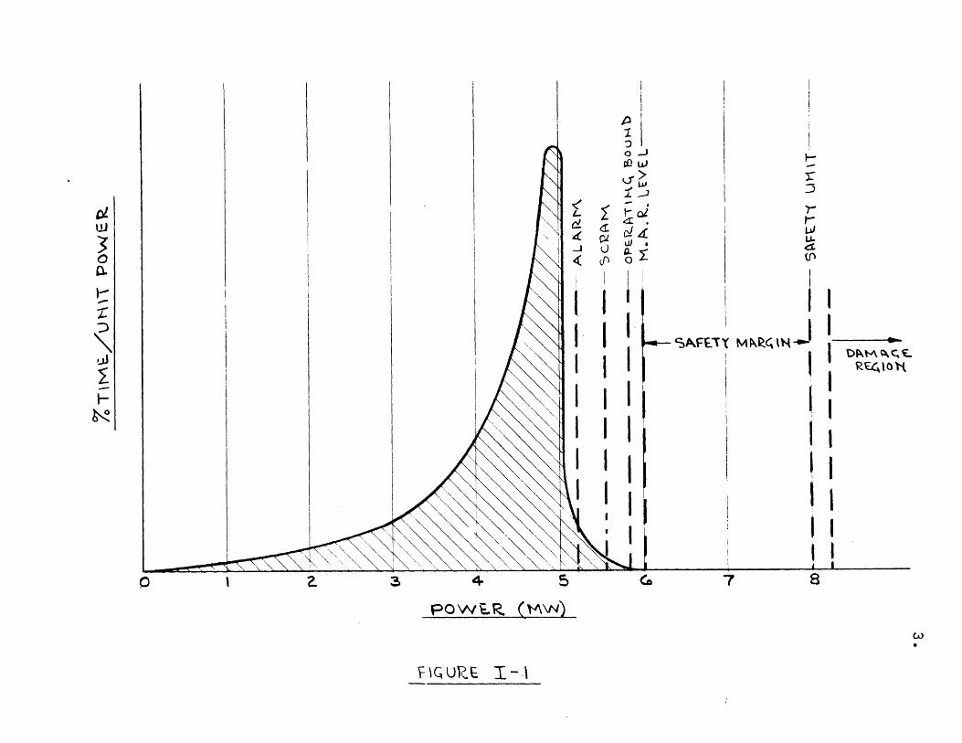
Consideration must be given to establishing a
consistent set of limiting safe values for the six parameters,
henceforth designated herein as the Primary Safety Parameters.
For purposes of these Specifications, the limiting safety values
will have the meanings shown in Fig. I-1 in which power has
arbitrarily been chosen as an example of a Primary Safety
Parameter to plot against percent of total reactor operating
time spent at each power increment. In MIT's case the licensed
reactor power is 5 Mw(t). Therefore, a good operator will
endeavor to maintain the reactor as close to 5 Mw(t) as
possible. It is almost inevitable that occasionally the
operator will exceed the 5 Mw(t) level and this occasional
drift over the line is shown by the toe of the 5 Mw curve just
%.T
IMV
-/U
t-\\
TV
PO
WE
R
C0
(,3_
or/
/
-Ti,
-4
IP -I
OD -
-'s "
A'
-om
m'
-t -
5XF
I U
V \T
0
c
4.
to the right of 5 Mw(t). This occurrence may also result from
slight variations in instrument calibration or for other
reasons. At some level, set by MIT, alarms may sound and, at a
still higher level, a scram will occur.
Other levels need to be stipulated. One such level
is designated as the Management Audit and Review Level (MARL).
If this level is exceeded a report must be prepared and
reviewed by the MIT Reactor management, setting forth the
circumstances and stipulating any conclusions and corrective
action taken. Since this report is available for AEC
inspection it seems appropriate that this level constitute
the lower bound of the Safety Margin, the upper bound of
which is the Safety Limit. The AEC and the applicant are then
in agreement as to the extent of the Safety Margin and,
further, the AEC will have available to it information of any
occurrences in which the Safety Margin is encroached upon.
The MAR level for most parameters in most reactors will
probably be best located above scram levels, but for some
parameters in some reactors it may be safer or more convenient
to reverse this order. As mentioned, the upper bound of the
Safety Margin is set by a Safety Limit beyond which it may be
unsafe to venture without seriously endangering the system or
beyond which there is a marked increase in the probability of
an unsafe condition developing. Beyond the Safety Limit is
the region where damage to fuel and release of fission
products is quite likely.
One further set of parameter values must be
stipulated--the values used for setting the reactor conditions
to calculate the Safety Limits. These levels should be ones
5.
that are seldom exceeded and then only by small amounts, and
they are here designated as the Operating Bounds, and they are
obviously the bounds in the direction of non-conservative
values. Conceivably, these values could be the nominal or
licensed levels, the scram points, or the MAR levels. Often
these three types of levels will be close together and it
will make little difference to the magnitude of the Safety
Margin which is chosen. The scram point will be a more
conservative choice than the licensed level, and the MAR level
still more conservative if it is above the scram point. In
this case, MIT has designated the Operating Bounds for all
Primary Safety Parameters as the MAR levels. This is the
most conservative choice; but, as indicated above, other
choices are possible and may be logically selected with an
ample margin of conservatism. The particular choice made by
MIT simplifies the Technical Specifications since it combines
two different sets of parameter values into one. Thus the
alarm and scram points remain undesignated in these
Specifications, except for the stipulation by MIT that these
points will fall within the operating band whose extreme
limit is the MAR level (now defined to coincide with the
Operating Bound level).
A maximum plate temperature of 4500 C (842 0 F) has
been chosen as the acceptable temperature limit for the
calculation of Safety Limits for the other measurable
parameters. At this temperature softening of the aluminum
begins to be significant, although actual melting does not
begin until somewhat above 6o0C (11120 F). It is believed
6.
that this establishes an adequate Safety Limit well below the
point where melting at the hot spot would begin and some fission
products would be released. A "real" Safety Limit might be said
to exist at the hot spot melting temperature above 600 0C.
In order to make a consistent, conservative, and
manageable set of Technical Specifications, the systems analysis
to determine appropriate Safety Limits is based upon two
important assumptions:
(1) Each of the Primary Safety Parameters is independentand controllable by independent means.*
(2) Two independent Primary Safety Parameters will notexceed simultaneously their respective Operating Bounds.
There are two justifications for these assumptions:
(1) By design of the process and safety systems andprocedures, two or more simultaneous failures ormalfunctions are required to produce significantchanges to two Primary Safety Parameters.
(2) The intent of management as evident by the operatingprocedures is to maintain control of all parameterswithin the MARL at all times.
This means that there must be a misoperation or equipment
failure affecting each of two independent parameters* followed
by a failure of the monitoring system for each parameter to
provide appropriate information and to take corrective action
(usually a scram). Thus there must be at least four simulta-
neous malfunctions or misoperations to invalidate the primary
assumptions of these Specifications. The only known important
interaction between the Primary Safety Parameters is produced
by loss of electrical power which produces an automatic
shutdown and, hence, a safer condition.
*The tank outlet D 0 temperature at power is an exception. Itwas chosen as a P imary Safety Parameter to limit thesecondary coolant system conditions, but it also is dependenton the primary system power and flow. For the purpose ofthis discussion it might almost be considered a secondaryparameter monitoring the primary system flow and power andproviding additional and independent means of takingcorrection action for those parameters.
For example, to set a Safety Limit for power, a steady-
state reactor was assumed with the flow rate, the reactor D20
outlet temperature, the D20 tank level, and the D2 concentra-
tion each, respectively, just as its Operating Bound. Then,
in order to establish a Safety Limit on power, it was imagined
that all power level safety circuitry was inoperative as power
was raised slowly until a calculated power was reached where
either the hot spot temperature was calculated to be 450 0C or
where conservative predictions indicated an unstable or burnout
condition. The lowest power level leading to either of these.
conditions was chosen as the Safety Limit on power. If doubt
existed concerning the validity of information in regard to a
certain performance region or calculational method, that
method or region was excluded. Thus the analysis was always
carried out in a conservative manner.
The situation is similar for other important
parameters. For instance, the calculation to set the flow
Safety Limit was made with the power, the D20 tank level,
the core D20 outlet temperature, and the D2 concentration
assumed each to be just at its Operating Bound as the flow was
decreased until a plate temperature of 45000 was reached or
until an instability was reached. This flow rate was
designated as the Safety Limit. Note that the flow Safety
Limit and the others are equally as important as the power
Safety Limit, and all must be treated in a similar manner if
a scientifically meaningful set of Technical Specifications
is to result.
7-
8.
The consideration involving core symmetry was found
necessary for the analysis and, therefore, must be a license
condition. It is likely that some condition with the same
objective will be necessary in other reactors since otherwise
asymmetric fuel loadings, small fuel loadings, or asymmetric
control rod configurations could lead to localized heat fluxes
or heat removal problems much more severe than those
envisioned in the calculations. This condition specified in a
conservative manner the general nature of the core used in
the calculations. In the case of the MITR, this amounted to
specifying at powers above 200 kw a core of at least 19 elements
controlled by rods banked within 4 in. of one another and
fueled with elements of a plate type with a specified acceptable
clad thickness, a minimum average void coefficient, and a
negative overall temperature coefficient.
These Technical Specifications have been written to
incorporate in the "Specifications" themselves and the
definitions all requirements which MIT believes are necessary
and sufficient to assure the safety of the MIT Reactor. The
"Bases" presented with the Specifications set forth the logic
and reasoning behind the choice of the Specification in
question. They also indicate to the extent possible the
uncertainty in the values selected for limits. It is the
intent of MIT to present these Bases solely as a backup for
the Specification itself--to provide the technical arguments
for the Specification chosen. No statement made in any
Basis should be construed as a limiting requirement within the
license. Once the set of Technical Specifications has been
9.
approved, the Bases should not longer be a part of the continuing
dialogue between MIT and the AEC unless the logic and reasoning
used in the Bases are found by either party to be incorrect and
nonconservative.
10.
II. DEFINITIONS
A. Primary Safety Parameters (Reactor)
The following controllable independent variables (except
for tank outlet D20 temperature at power) are designated
as "Primary Safety Parameters":
Reactor Primary System Power (neutron flux)
Primary Coolant (D2 0) Volume Flow Rate
Tank Outlet D 0 Temperature at Power (Limits secondarycoolant ondition, but also depends on power andflow)
Step Reactivity Addition
Tank Level (D20) with Reactor Critical
Deuterium Gas Concentration
The several operational conditions of the reactor system
mentioned in these Specifications are defined in terms of
these variables and Safety Limits are determined in terms
of them.
B. Secondary Safety Parameters (Reactor)
The following variables are designated as "Secondary
Safety Parameters":
Reactor Period (neutron flux)
Containment External-Internal AP
Effluent Air Radiation Levels
Effluent Liquid Waste Radiation Levels
Reactor Room Radiation Levels
Equipment Room Radiation Levels
Exceeding certain operating limits of these Secondary
Safety Parameters will result in a scram or other safety
ll.
action. However, no limiting value of these parameters are
considered as Safety Limits in the sense defined under F
below. All of these parameters except the first, reactor
period, provide information and require safety actions at
appropriate levels to insure compliance with AEC regulations
10CFR20 and 10CFR100.
C. Normal Operating Levels
The range of parameter values within which the system
normally operates. The normal operating points for all
parameters fall within this range and are quite well-
designated and closely followed--for instance, the licensed
power level is such a point. The limit of the normal
operating range in a nonconservative direction for a
Primary Safety Parameter is a scram level. For purposes
of these Specifications only, scram levels will be equally
conservative or more conservative than Management Auditing
and Review levels, but they are not deemed to be a part
of these Technical Specifications and are not contained
herein.
D. Operating Bound Limit (OBL)
A bound in the nonconservative direction which sets the
other Primary Safety Parameter values to be used as the
reactor conditions for calculation of the Safety Limit
for one Primary Safety Parameter.
E. Management Auditing and Review Level (MARL)
The Primary Safety Parameter value which, if exceeded,
will result in an audit of the abnormal occurence by the
12.
reactor management and the preparation of a written review xe-
port Uescribing the occurence, giving the results of the
review, and stating any corrective action taken. For purposes
of these Specifications only, the MARL is defined to
coincide with the OBL.
F. Safety Limit
A limit set for a given parameter beyond which it may be
unsafe to venture without seriously endangering the system
or beyond which there is a marked increase in the probability
of an unsafe condition developing. The values selected are
based on experiments or conservative calculations and are,
in general, more conservative than the true or ultimate
safety limits. In cases where incomplete information exists
these limits are set conservatively. The Safety Limits for
the Primary Safety Parameters are set so as to insure that
gross fuel melting will not occur within the Safety Limit.
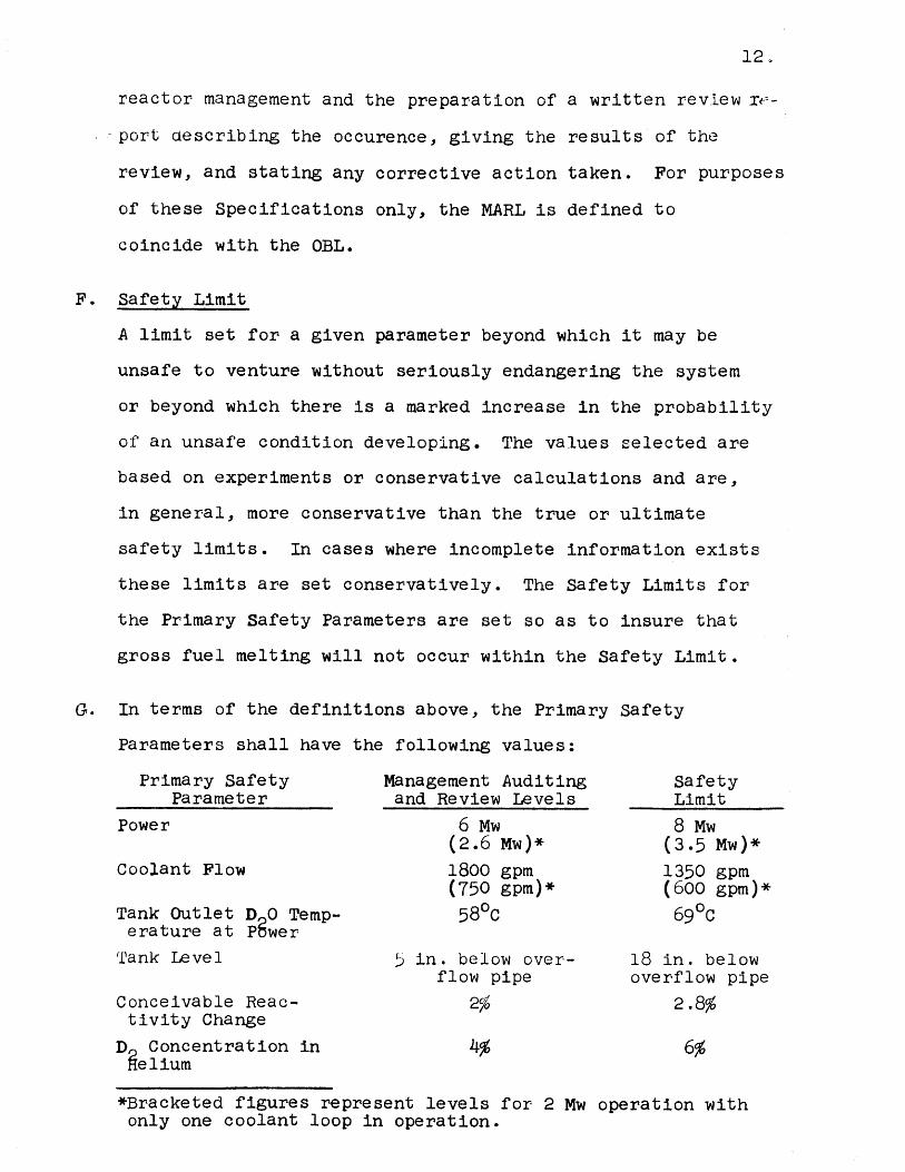
G. In terms of the definitions above, the Primary Safety
Parameters shall have the following values:
Primary Safety Management Auditing SParameter and Review Levels L
Power 6 Mw 8(2.6 Mw)* (3
Coolant Flow 1800 gpm 13(750 gpm)* (6
Tank Outlet D 0 Temp- 580C 6erature at P~wer
Tank Level 5 in. below over-flow pipe
18 inoverf
afetyimit
Mw.5 Mw)*50 gpmD0 gpm)*90C
. belowlow pipe
Conceivable Reac- 25 2.8%tivity Change
D Concentration in 4% 6%elium
*Bracketed figures represent levels for 2 Mw operation withonly one coolant loop in operation.
H1. Normal Reactor Shutdown
The reactor is said- to be shut down normally if the following
conditions exist:
(a) All shim control rods in.
(b) Primary coolant system on either normal or shutdownflow.
(c) Reactor power at levels set by (7,n) interactions.
(d) Reactor tank level either at overflow level or atdump level.
(e) Primary outlet coolant temperature given by (T)< 5300.
I. Maximum Security
The reactor facility is said to be in a condition of maximum
security if the following conditions exist:
(a) All shim control rods in and magnets run down.
(b) Ventilation fans off.
(c) Quick operating ventilation dampers and back-updampers closed.
(d) Reactor tank D 0 level at or above dump level orfuel under eme gency cooling provisions.
(e) City make-up water supply to the cooling tower offand lines to City sewer system closed. Coolingtower fans and sprays off with water flowing onlyinto the basin.
(f) H 0 City emergency supply checked to assure availa-bility and connected by emergency connection toD20 system.
(g) The containment area and its immediate environspositively secured.
(h) Only personnel authorized by the supervisor incharge within the restricted area.
T. Review and Approve
The terminology "shall review and approve" is to be inter-
preted as requiring that the reviewing group or person
shall carry out a review of the matter in question and may
then either approve or disapprove it. Before it can be
implemented, the matter in question must receive an
approval from the reviewing group or person.
13.
14.
III. SAFETY LIMITS
These conditions assure that fuel plates will not
melt and that no other serious harm which could
affect the health and safety of operators or the
general public will come to the reactor.
15.
III.l. MAXIMUM STEADY STATE POWER LEVEL
Applicability
This specification applies to the steady state thermal
reactor power level.
Objective
To ensure that the temperature of the hottest fuel
plate will not exceed 450 0 C (8420F).
Specification
The Safety Limit for the steady state thermal reactor
power level shall be 8 Mw. (The Safety Limit for one-loop
operation shall be 3.5 Mw.)
Bases
Although aluminum melts at approximately 650 0C
(12000F), it begins to soften significantly at about 4500 C
(8420F) and this temperature is therefore a suitable criterion
for guaranteeing the structural integrity of the fuel elements.
Since the MITR operates at atmospheric pressure and
since the fuel elements incorporate thin aluminum fuel plates,
simple calculations show that the difference of about 350 0C
between 4500 c (8420F) and boiling could not be reached if
boiling burnout is prevented. Due to the same reasons and
the additional fact that the coolant flow path in the core is
of multichannel design, there exists the possibility that
flow instabilities could occur before reaching burnout
SIt is possible that for the conditions present in a core ofthis type the usual model for predicting burnout ("departurefrom nucleate boiling" or "film boiling") does not applyand that the heat flux could be pushed even higher before.reaching the limiting temperature.
16.
limitations. If flow instability does occur first, it would
have the effect of lowering the burnout heat flux to some
extent, but the exact amount is at the present time very
difficult to predict. In view of this difficulty, it is
assumed here that the onset of flow instability causes a
lower flow rate in one channel for the same pressure drop and
thus causes burnout at a lower heat flux than would be
computed from the average flow conditions of the channels.
It should be noted that this is a conservative assumption
based on the limitations of the present state of the art.
This fact combined with the conservative assumptions used in
predicting the onset of flow instability produces a safety
limit of the maximum steady state thermal reactor power that
is considerably below values based on applicable burnout
correlations. Thus there appears to be a comfortable margin
beyond this safety limit before reaching the point where a
real threat to fuel element integrity exists.
The method of investigating the onset of flow
instability consists of calculating the pressure drop as a
function of flow rate for a given heat flux. The minimum
stable flow rate is that which coincides with the minimum of
the curve. This is consistent with the stability criterion
below:
For instability:
(AP external syst.) - W (AP coolant channel) O . (1)
Since, for a large number of channels,
AP ext. syst. = constant ,
17.
the criterion reduces to:
- (AP coolant channel)?-0 .(2)
This theoretical model has been proposed in several references,
(1), (2), and (3), and has recently been found to give
excellent agreement with experiment (3).
In the case of the MITR fuel element some interpreta-
tion is necessary in order to define the coolant channel. The
entire fuel element could be considered a coolant channel,
since there are 19 to 30 elements in the core and the
assumption of a constant pressure drop across the fuel elements
is not significantly affected by flow changes in any one
element. The alternative is to treat the individual channels
between fuel plates of which there are 17 per standard element,
and less for reduced plate elements. This distinction has
considerable bearing on the results and as will be seen below
the latter case is the more conservative and has therefore
been used in this analysis.
The pressure drop across the coolant channel can be
divided into four parts:
(1) the entrance effect
(2) the friction factor drop along the length ofthe channel
(3) the exit effect
(4) the gravity drop--since the flow is verticaland upward.
In the absence of boiling, these pressure drops are normally
computed by standard methods and, except for the last one
which is independent of flow rate, are an increasing function
of flow rate, i.e., the slope of the pressure drop vs. flow
18.
curve is positive and there is no flow instability. The
presence of boiling in the channel affects all except possibly
the first factor. In general, the entrance effect and the
exit effect are increasing functions of flow rate, but their
magnitudes may be decreased by the transition to two-phase
flow. The friction drop may have either a positive or
negative slope and may be considered the determining factor.
Having defined the coolant channels as the individual
channels between fuel plates, the entrance effect becomes both
small and difficult to calculate due to the geometry of the
MITR fuel element lower adapter. For these reasons this
pressure drop has been neglected, introducing a conservative
factor.2 Since this term would be relatively large and have
a positive slope with respect to flow rate for the case of an
entire element considered as a coolant channel, the selection
of the individual fuel plate channels as the coolant channels
is quite conservative.
The exit effect pressure drop is also negligible
for the individual channels, but would be significant for the
whole element. It has therefore also been neglected and, for
reasons similar to those given above, this represents another
conservative factor.
Similarly, the gravity drop becomes an increasing
function of flow rate for two-phase flow, but requires
knowledge of the void fraction which is extremely difficult
to predict. Neglecting this term then adds still another
conservative factor.
2A relatively simple fuel element modification incorporatingorificing for the coolant channels could probably produce asubstantial improvement in stability by adding an entranceeffect pressure drop.
19.
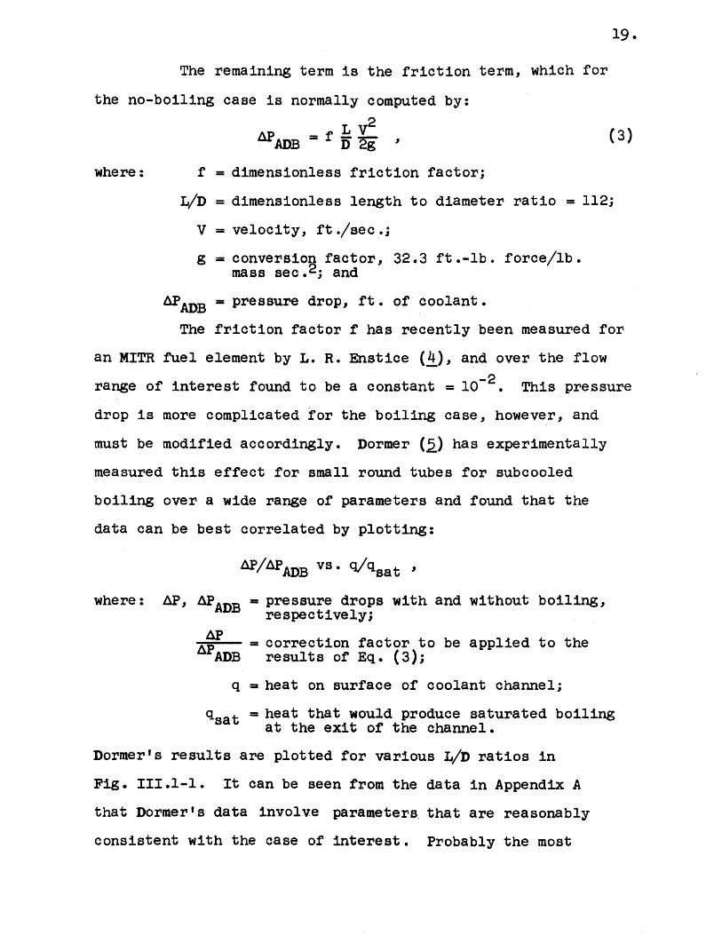
The remaining term is the friction term, which for
the no-boiling case is normally computed by:
AP fLV2(3)ADB
where: f = dimensionless friction factor;
L/D = dimensionless length to diameter ratio = 112;
V = velocity, ft./sec.;
g = conversion factor, 32.3 ft.-lb. force/lb.mass sec.2 ; and
APADB = pressure drop, ft. of coolant.
The friction factor f has recently been measured for
an MITR fuel element by L. R. Enstice (4), and over the flow
range of interest found to be a constant = 10-2 This pressure
drop is more complicated for the boiling case, however, and
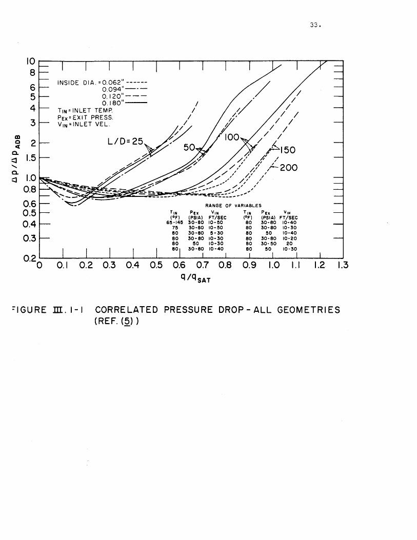
must be modified accordingly. Dormer (5) has experimentally
measured this effect for small round tubes for subcooled
boiling over a wide range of parameters and found that the
data can be best correlated by plotting:
AP/APADB vs sat'
where: AP, APADB = pressure drops with and without boiling,respectively;
= correction factor to be applied to theAPADB results of Eq. (3);
q = heat on surface of coolant channel;
qsat = heat that would produce saturated boilingat the exit of the channel.
Dormer's results are plotted for various L/D ratios in
Fig. III.1-1. It can be seen from the data in Appendix A
that Dormer's data involve parameters that are reasonably
consistent with the case of interest. Probably the most
20.
questionable factor involving its use in the present case is
that the data were obtained for round tubes, while the coolant
channels of interest are narrow rectangular channels.
Griffith has stated (6), however, that the concept of a hydraulic
diameter is meaningful for this purpose, so that the use of the
data is justified.
If all other parameters are unchanged, a reduction
in flow will decrease qsat and thereby increase r/qsat, here-
after referred to as R. Referring to Fig. III.1-1, if R is
sufficiently large (for the prescribed L/D curve), &P/APADB is
an increasing function of R. This behavior may be interpreted
as a pressure drop vs. flow relationship with a negative slope
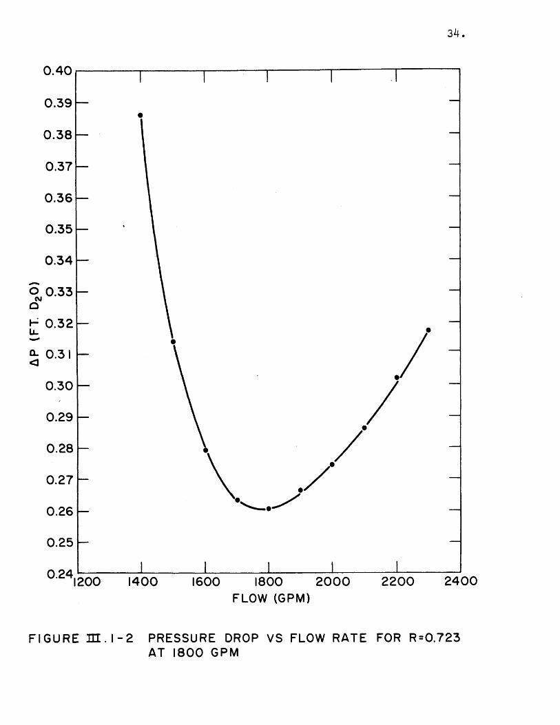
as opposed to the positive slope of Eq. (3). The flow rate at
which the product of APADB and AP/APADB is a minimum then
corresponds to the minimum stable flow rate for the prescribed
conditions as, for example, in Fig. 111.1-2.
The actual calculation of R used to enter
Fig. III.1-1 involves other system parameters, specifically:
reactor power, the power produced in the hottest plate of the
hottest fuel element, the D20 flow rate, and the D20 inlet
temperature. The D20 flow rate has been fixed at 1800 GPM,
the OBL value. The power produced in the hottest plate of
the hottest fuel element is obviously a function of power
and has been taken to be also a function of the number of
elements in the core. This is meaningful since for a given
reactor power the power per plate is decreased if the number
of fuel elements is increased. To be consistent, this
relationship has been taken to be equivalent to that
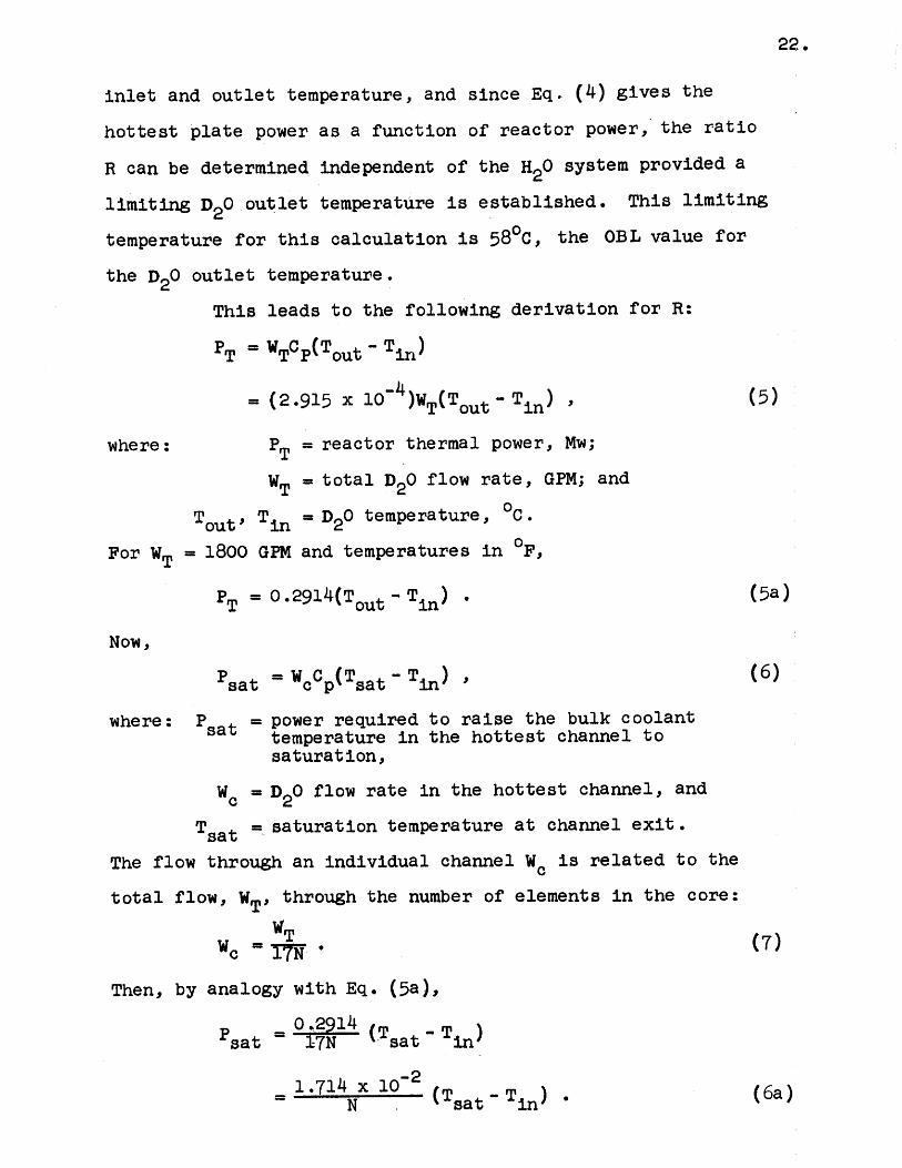
21.
established for the prevention of nucleate boiling at 6 Mw
with a D20 outlet temperature of 550C (7) then:
P 500(1.25) 90. P ~T(4
O.8PPMAX 7.82 x 10⁻³ (19 , (4a)
where: P1 = maximum power per hottest plate (Mw),
N = number of elements in the core, and
PT= reactor thermal power (Mw).
This relationship is counterbalanced by the effect
of the decreased flow per coolant channel when the number of
fuel elements is increased and the total D20 flow rate is
kept constant at 1800 GPM. The net effect of the dependence
upon the number of elements is to make the 30-element core
(maximum number) the closest to instability and the final
calculations are based on this case. It should also be noted
that the use of Eq. (4) establishes hottest plate power
values which are considerably higher than those predicted
by Devoto (8), including hot channel factors, and are
therefore conservative in that sense.
Since reactor power is a variable parameter for
the purpose of this calculation, there remains only the
relationship with the D2 0 inlet temperature. At a given time
the actual value of the D20 inlet temperature will be
determined by a number of factors, such as the outside wet
bulb temperature, the cooling tower effectiveness, the H20
flow rate, the overall heat exchanger heat transfer
coefficient, and the D2 0 flow rate. For a given power and
flow, however, there is a simple relationship between the
22.
inlet and outlet temperature, and since Eq. (4) gives the
hottest plate power as a function of reactor power, the ratio
R can be determined independent of the H20 system provided a
limiting D2 0 outlet temperature is established. This limiting
temperature for this calculation is 580C, the OBL value for
the D20 outlet temperature.
This leads to the following derivation for R:
PT = WTCp(Tout - Tin)
= (2.915 x 10~ )WT(Tout T in) , (5)
where: PT = reactor thermal power, Mw;
WT = total D2 0 flow rate, GPM; and
Tout, Tin = D20 temperature, 0C.
For WT = 1800 GPM and temperatures in F,
PT = 0.291 4(Tout- T in) . (5a)
Now,
Psat =Wc0p(Tsat - Tin) , (6)
where: P sat = power required to raise the bulk coolanttemperature in the hottest channel tosaturation,
Wc = D20 flow rate in the hottest channel, and
Tsat = saturation temperature at channel exit.
The flow through an individual channel W c is related to the
total flow, WT, through the number of elements in the core:
WcI7*
Then, by analogy with Eq. (5a),
sat = 17N (Tsat - Tin)
= 714 N 2 (Tsa - T in) . (6a)
Using Eq. (5a) to substitute for Tin gives:
sat Nx 10 sat + 3 4 2PT - Tout) (6b)
Now, by definition,
R q - (8)sat sat
7.82 x 10~ (9) M P
-2 N T (a1.714 x 10 (T + 3.43 PT - ToutN ~(sat T ot
4.81 N0 .2 T (8b)
(Tsat + 3.43 PT out.(8)
Since the H20 saturation temperature is approximately
215 0F for a pressure of 15.5 psia (local pressure at channel
exit), this is a conservative value for D2 0'
Taking Tsat = 215,0 and N = 30,
9.494 PTR = (215 + 3.43 PT - Tout) (8c)
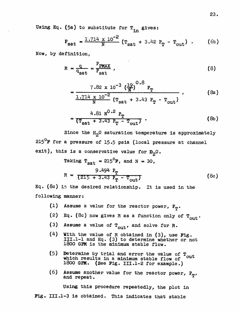
Eq. (8c) i the desired relationship. It is used in the
following manner:
(1) Assume a value for the reactor power, PT*(2) Eq. (8c) now gives R as a function only of Tout*
(3) Assume a value of Tout, and solve for R.
(4) With the value of R obtained in (3), use Fig.III.1-1 and Eq. (3) to determine whether or not1800 GPM is the minimum stable flow.
(5) Determine by trial and error the value of T0otwhich results in a minimum stable flow of1800 GEM. (See Fig. 111.1-2 for example.)
(6) Assume another value for the reactor power, PT,and repeat.
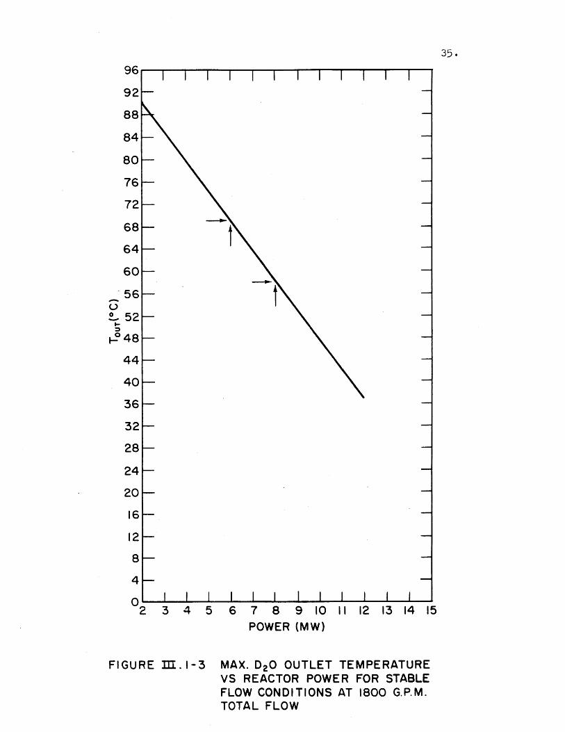
Using this procedure repeatedly, the plot in
Fig. III.1-3 is obtained. This indicates that stable
23.
24.
conditions exist for a total flow of 1800 GPM provided operating
conditions correspond to a point below and to the left of the
line of Fig. 111.1-3. As can be seen from the graph, the
Safety Limit of 8 Mw is consistent with the OBL value of 580C
for the D20 outlet temperature.
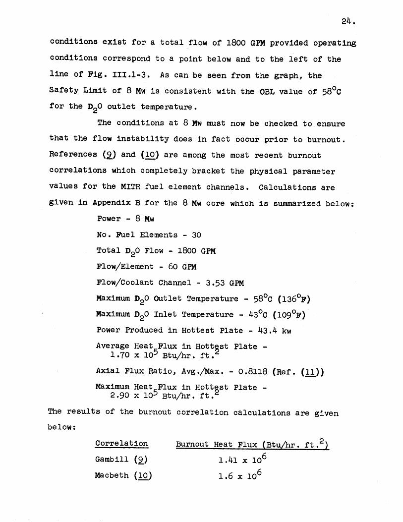
The conditions at 8 Mw must now be checked to ensure
that the flow instability does in fact occur prior to burnout.
References (Q) and (10) are among the most recent burnout
correlations which completely bracket the physical parameter
values for the MITR fuel element channels. Calculations are
given in Appendix B for the 8 Mw core which is summarized below:
Power - 8 Mw
No. Fuel Elements - 30
Total D20 Flow - 1800 GPM
Flow/Element - 60 GPM
Flow/Coolant Channel - 3.53 GPM
Maximum D20 Outlet Temperature - 580C (136 0F)
Maximum D20 Inlet Temperature - 4300 (1090F)
Power Produced in Hottest Plate - 43.4 kw
Average Heat Flux in Hottrst Plate -1.70 x 10⁵ Btu/hr. ft.
Axial Flux Ratio, Avg./Max. - 0.8118 (Ref. (11))
Maximum Heat 5Flux in Hottgst Plate -2.90 x 10 Btu/hr. ft.
The results of the burnout correlation calculations are given
below:
Correlation Burnout Heat Flux (Btu/hr . ft. 2
Gambill (Q) 1.41 x 10⁶
Macbeth (10) 1.6 x 10⁶
25.
The two correlations are in good agreement and while it is not
clear whether the results should be compared with the average
or the maximum heat flux in the hottest plate, even the maximum
value is exceeded by a factor of about 5. It can be concluded,
therefore, that boiling burnout will not occur for the 8 Mw
core considered.
The upper Operating Bound (OB) level of 6 Mw is based
on calculations of that power which will just allow the plate
surface temperature at the hot spot to reach 1000C. In this
way, a very conservative limit has been established that
precludes any possibility of boiling in the core. It should
be noted here that no credit has been taken for the film
temperature drop. In addition, nucleate boiling in the core
should have no adverse effect and, in fact, it is reasonably
certain that the reactor could be raised to power well above
8 Mw without encountering any serious adverse effects.
In addition, the 6 Mw level is far enough above the
5 Mw licensed power to permit the setting of power scram
levels at intermediate values between 5 Mw and 6 Mw, and yet
6 Mw is now so far way from 5 Mw as to significantly affect
the hypothetical accident conditions and fission product
releases calculated.
It should be pointed out that this choice of 6 Mw for
the OB level and 8 Mw for the Safety Limit is somewhat
arbitrary and could be raised, for instance, by cutting into
the flexibility allowed here for future fuel element design.
The choice of any parameter Safety Limit or OB level in the
case of flow, power, and Tout depends on its interaction with
26.
the other two. In particular, the choice of the 8 Mw Safety
Limit depends on the acceptable (OB) coolant outlet temperature,
the acceptable (OB) coolant flow, and the maximum acceptable
power developed per fuel element plate. The choices made of
the limits are designed to correspond to the present well-
verified operating conditions while still providing reasonably
large margins between the Safety Limits and the OB levels and
providing sufficient flexibility in core loading patterns and
fuel designs.
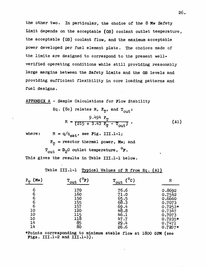
APPENDIX A - Sample Calculations for Flow Stability
Eq. (8c) relates R, PT, and Tout:
9.494 PTR = (215 + 3.43 PT - Tout
where: R = /qsat'see Fig. III.1-1;
PT = reactor thermal power, Mw; and
Tout = D20 outlet temperature, 0F
This gives the results in Table III.1-1 below.
Table III.1-1 Typical Values of R from Eq. (Al)
PT (Mw) Tout (OF) Tout (OC) R
6 170 76.6 0.86926 160 71.0 0.75426 150 65.5 0.66606 155 68.3 0.70736 157 69.4 0.7253*
10 120 48.8 0.734710 115 46.1 0.707310 118 47.7 0.7235*14 85 29.4 0.747114 80 26.6 o.7207*
*Points corresponding to minimum stable flow at 1800 GPM (seeFigs. 111.1-2 and 111.1-3).
27.
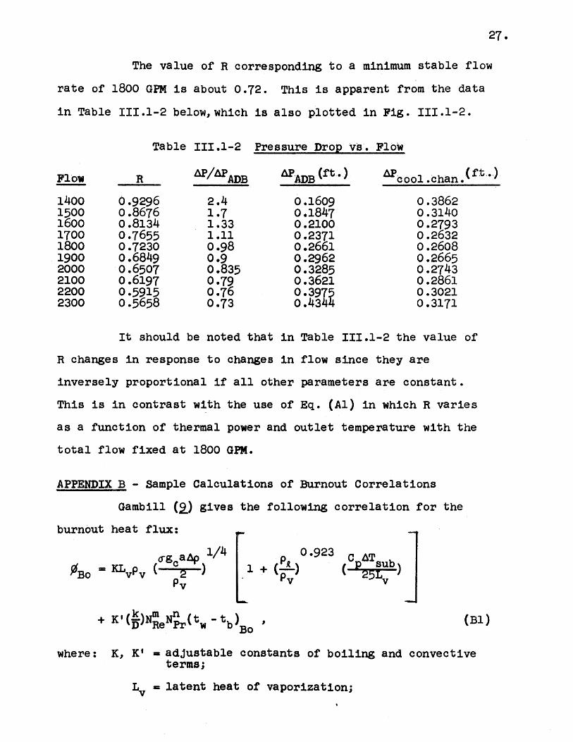
The value of R corresponding to a minimum stable flow
rate of 1800 GPM is about 0.72. This is apparent from the data
in Table 111.1-2 below, which is also plotted in Fig . 111.1-2.
Table 111.1-2 Pressure Drop vs'. Flow
APAADB
2.41.71.331.110.980 .90.8350.790.760.73
AADB (ft.)
0.16090.18470.21000.23710.26610.29620.32850.36210.39750.4344
AP cool .chan. ft.
0.38620.31400.27930.26320.26080.26650.27430.28610.30210.3171
It should be noted that in Table 111.1-2 the value of
R changes in response to changes in flow since they are
inversely proportional if all other parameters are constant.
This is in contrast with the use of Eq. (Al) in which R varies
as a function of thermal power and outlet temperature with the
total flow fixed at 1800 GPM.
APPENDIX B - Sample Calculations of Burnout Correlations
Gambill (Q) gives the following correlation for the
burnout heat flux:
6Bog a~±)1/4
OBo = K vpv 2Pv
1+
0.923 C AT
(E) (25Lv
+ K'1(D)NRe r w tb)o
I(B1)
where: K, K' = adjustable constants of boiling and convectiveterms;
Lv = latent heat of vaporization;
Flow
1400150016001700180019002000210022002300
R
0.92960.86760.81340.76550 .72300.68490.65070.61970.59150.5658
28.
p = density of vapor;
' surface tension;
go = conversion constant, L-M/F-92
a = local acceleration;
Ap = density difference (p - pv);
C = constant pressure specific heat of liquid;
p = density of liquid;
ATsub = degree of subcooling (t sat - tb);
k = thermal conductivity of liquid;
D = equivalent diameter of flow passage;
NRe = Reynold's number;
NPr = Prandtl number;
m,n = exponents; and
tw = wall temperature at burnout.
This correlation is based on a physical model and the
first term corresponds to the boiling heat transfer at burnout
while the second term corresponds to non-boiling or convective
heat transfer at burnout. The use of the second term requires
knowledge of t., the wall temperature at burnout, and the
method proposed for predicting (12) tw does not cover the
temperatures of interest for low pressure cases. This
apparently is a result of the fact that the convective term is
significant only for the higher pressures. In any event, this
term has been neglected in the present case, and any error so
introduced will be conservative.
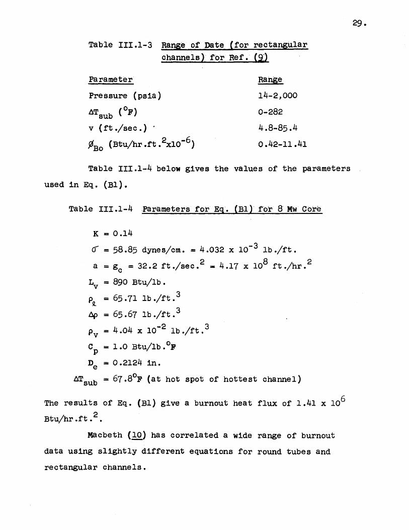
Table 111.1-3 below gives the extreme ranges of some
of the physical parameters covered by the data correlated.
29.
Table 111.1-3 Range of Date (for rectangular
channels) for Ref. (:)
Parameter Range
Pressure (psia) 14-2,000
ATsub (OF) 0-282
v (ft./sec.) 4.8-85.4
IBo (Btu/hr .ft .2x106) 0.42-11.41
Table 111.1-4 below gives the values of the parameters
used in Eq. (Bl).
Table 111.1-4 Parameters for Eq'. (Bl) for 8 Mw Core
K = 0.14
' = 58.85 dynes/cm. = 4.032 x 10- 3 lb./ft.
a = go = 32.2 ft./sec.2 = 4.17 x 10 ft./hr.2
L = 890 Btu/lb.
p = 65.71 lb./ft. 3
Ap = 65.67 lb./ft .3
pv = 4.04 x 10⁻² lb./ft.3
Cp = 1.0 Btu/lb.0F
De = 0.2124 in.
ATsub = 67.8 0F (at hot spot of hottest channel)
The results of Eq. (Bl) give a burnout heat flux of 1.41 x 10⁶
Btu/hr.ft.2
Macbeth (10) has correlated a wide range of burnout
data using slightly different equations for round tubes and
rectangular channels.
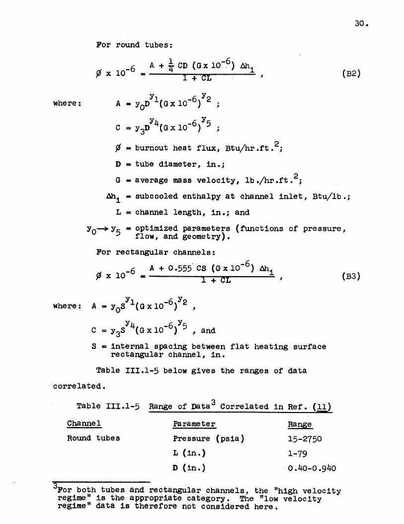
For round tubes:
0 x 106 -
1 6A + CD (G.x 10- 6 h
S+ C
A = yOD l(G x 10-6 2
C = y 3 D 4 (G x 10-6 5
= burnout heat flux, Btu/hr.ft. 2
D = tube diameter, in.;
G = average mass velocity, lb./hr.ft 2
Ah i= subcooled enthalpy at channel inlet, Btu/lb.;
L = channel length, in.; and
yO-- y5- optimized parameters (functions of pressure,
flow, and geometry).
For rectangular channels:
0 x 106A + 0 .555 CS (G x 10-6) i
(B3)
where: A = yOS (G x 10-6 )2
C = y3 (G x 10-6 )Y5 , and
S = internal spacing between flat heating surfacerectangular channel, in.
Table 111.1-5 below gives the ranges of data
correlated.
Table 111.1-5 Range of Data3 Correlated in Ref . (11)
Channel
Round tubes
Parameter
Pressure (psia)
L (in.)
D (in.)
Range
15-2750
1-79
0.40-0.940
3For both tubes and rectangular channels, the "high velocityregime" is the appropriate category. The "low velocityregime" data is therefore not considered here.
30.
where:
(B2)
I + CL
31.
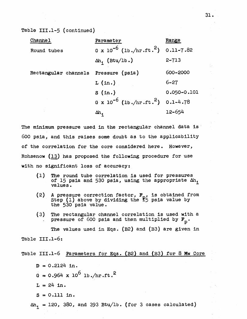
Table 111.1-5 (continued)
Channel Parameter
Round tubes G x 106 (lb./hr.ft.2) 0.11-7.82
Ahi (Btu/lb.) 2-713
Rectangular channels Pressure (psia) 600-2000
L (in.) 6-27
S (in.) 0.050-0-101
0 x 10-6 (lb./hr.ft. 2 ) 0.1-4.78
Ah 112-654
The minimum pressure used in the rectangular channel data is
600 psia, and this raises some doubt as to the applicability
of the correlation for the core considered here. However,
Rohsenow (13) has proposed the following procedure for use
with no significant loss of accuracy:
(1) The round tube correlation is used for pressuresof 15 psia and 530 psia, using the appropriate Lhvalues.
(2) A pressure correction factor, F , is obtained fromStep (1) above by dividing the 15 psia value bythe 530 psia value.
(3) The rectangular channel correlation is used with apressure of 600 psia and then multiplied by F .
The values used in Eqs. (B2) and (B3) are given in
Table 111.1-6:
Table 111.1-6 Parameters for Eqs. (B2) and (B3) for 8 Mw Core
D = 0.2124 in.
G = 0.964 x 10⁶ lb./hr.ft.
L = 24 in.
S = 0.111 in.
Ah = 120, 380, and 393 Btu/lb. (for 3 cases calculated)
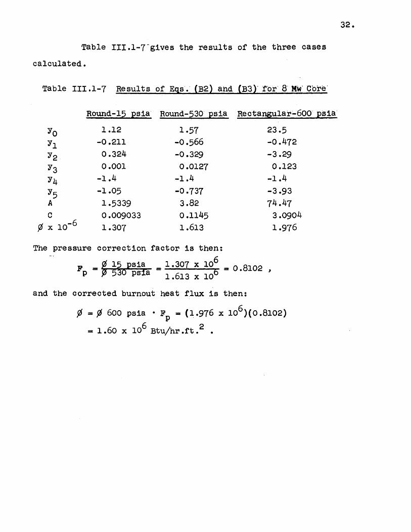
32.
Table III.l-7~gives the results of the three cases
calculated.
Table 111.1-7 Results of Eqs. (B2) and (B3)' or 8 M Cotre
Round-15 psia Round-530 psia Rectangular-600 psia
1.12
-0o.211
0.3240.001
-1.4-1.05
1.53390.009033
1.307
1.57-0.566-0.3290.0127
-1.4
-0.737
3.820.1145-1.613
23.5-0.472-3.290.123
-1.4
-3.93
74.473.09041.976
The pressure correction factor is then:
F = 0 15 psia _1.307 x 106 -. 8102F - -530pa 1.6.13 x 108
and the corrected burnout heat flux is then:
= 600 psia Fp = (1.976 x 1o6)(0.8102)
= 1.60 x 10⁶ Btu/hr.ft 2
yo
y2
y3
y5A
C
33.
108-
6 INSIDE I
5-4 TIN=INLI
PEX=EXI3 ~-~ VIN=INL
S2-
..-
1.00. 8
0. 6-0.5 -0.4-
0.3
0.20 0.1 C
:IGURE III. 1-1
.2 0.3 0.4 0.5 0.6 0.7 0.8 0.9 1.0 1.1 1.2 1.3
CORRELATED(REF. (5) )
PRESSURE DROP - ALL GEOMETRIES
0.40
0.39
0.38
0.37
0.36
0.35
0.34
0.31
0.30
0.29-
0.28-
0.27-
0.26-
0.25
.I
0.33 -
0.32 r-
1200 1400 1600 1800FLOW (GPM)
FIGURE IMI.1-2 PRESSURE DROP VS FLOW RATEAT 1800 GPM
FOR R=0.723
34.
0
I-La-
2000 2200 2400I I I I
I I
I024 '
96
92
88
84
80
76
72
68
64
60
56
* 52
s*48
44
40
36
32
28
24
20
16
12
8
4
0 1 I I I I I I I I I I 1 12 3 4 5 6 7 8 9 10 11 12 13 14 15
POWER (MW)
FIGURE IlI.1-3 MAX. D20 OUTLET TEMPERATUREVS REACTOR POWER FOR STABLEFLOW CONDITIONS AT 1800 G.P.M.TOTAL FLOW
35.
36.
111.2. MINIMUM D' O' FLOW RATE
Applicability
This specification applies to the D20 flow rate.
Objective
To ensure that the temperature of the hottest fuel
plate will not exceed 4500O (8420F).
Specification
The Safety Limit for the D20 flow rate shall be1350 GPM through the fuel elements. (The Safety Limit for one
loop operation shall be 600 GPM.)
Bases
Using the Operating Bound values for reactor power
and D20 outlet temperature, 6 Mw and 5800, the minimum stable
D2 0 flow is 1350 GPM, using the same approach as in Section
III.l. (In a similar manner, 2.6 Mw and 580C gives a minimum
stable flow of 600 GPM.)
The lower Operating Bound level of 1800 GPM for
coolant flow has been established, first, on the basis that
flows in excess of this value can be attained easily in
normal operation. Second, at flows less than this value and
with a tank outlet temperature of 580C there is a possibility
of the onset of flow instability at power levels greater
than 8 Mw. As indicated in Section III.1 the selection of
OB levels and Safety Limits on power, flow, and outlet D20
temperature are interrelated.
37.
111.3. MAXIMUM D 0 OUTLET TEMPERATURE
Applicability
This specification applies to the D 20 outlet tempera-
ture.
Objective
To ensure that the temperature of the hottest fuel
plate will not exceed 45000 (8420F).
Specification
The reactor shall not be critical with the D20
outlet temperature greater than 6900.
Bases
By using the Operating Bound levels for reactor
power and D20 flow rate, 6 Mw and 1800 GPM, the minimum stable
flow condition is found when the D2 0 outlet temperature is
raised to 690C. The calculations leading to these values
utilize the methods of Section III.l. The results are shown
in Fig. 111.1-3 of Section III.l.
The upper Operating Bound level of 580C for the
D20 core outlet temperature has been established, first, on
the basis that values of the outlet temperatures of 35-500C
depending upon cooling tower conditions are those normally
observed in the operation of this system and, hence, 5800
would be sufficiently above normal to make an audit of the
situation fruitful. Second, the choice of this value permits
the establishment of satisfactory limits for power, coolant
flow, and fuel element design.
38.
111.4. MAXIMUM SAFE STEP REACTIVITY ADDITION
Applicability
This specification applies to step reactivity
additions.
ObJective
To ensure that the surface temperature of the
hottest fuel plate will not exceed 450 C during any credible
reactivity excursion.
Spec if icat ion
The maximum amount of reactivity that may be added
in a stepwise manner by the credible failure or malfunction
of any experiment or component or any set of circumstances
which could credibly couple two or more components or experi-
ments in such a manner shall not exceed 2.8% in reactivity.
Bases
Technical Bases
The present "Maximum Credible Accident" to the MITR
is defined in the 5 Mw Report (7) as the sudden insertion of
a 160-gram element into the central position of a just
critical core which would add 2.8% reactivity.
The subsequent formation of steam voids in the core
will shut the reactor down before melting occurs in the fuel
elements. The maximum fuel plate temperature was estimated
to be about 3000C by using the approach outlined in Ref. (14),
based on experiments conducted on H20-moderated cores in the
Borax and Spert programs.
Since that report, transient experiments have
been conducted on D20-moderated cores as part of the Spert
39.
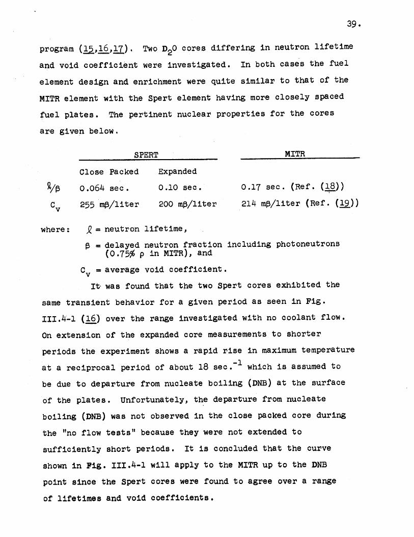
program (1,16,17). Two D20 cores differing in neutron lifetime
and void coefficient were investigated. In both cases the fuel
element design and enrichment were quite similar to that of the
MITR element with the Spert element having more closely spaced
fuel plates. The pertinent nuclear properties for the cores
are given below.
SPERT MITR
Close Packed Expanded
/A o.064 sec . 0.10 sec. 0.17 sec. (Ref. (18))
Cv 255 mp/liter 200 ms/liter 214 ms/liter (Ref. (19))
where: A = neutron lifetime,
= delayed neutron fraction including photoneutrons(0.75% p in MITR), and
C = average void coefficient.
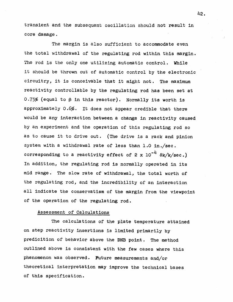
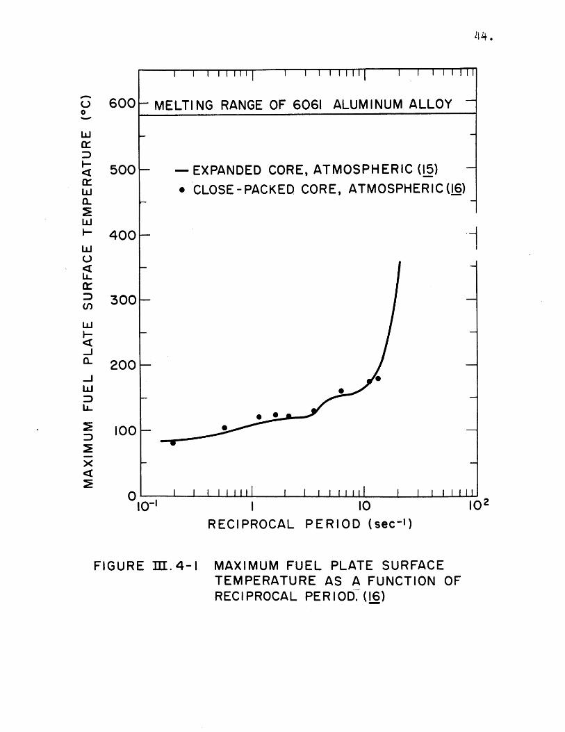
It- was found that the two Spert cores exhibited the
same transient behavior for a given period as seen in Fig.
III.4-1 (16) over the range investigated with no coolant flow.
On extension of the expanded core measurements to shorter
periods the experiment shows a rapid rise in maximum temperature
at a reciprocal period of about 18 sec.- which is assumed to
be due to departure from nucleate boiling (DNB) at the surface
of the plates. Unfortunately, the departure from nucleate
boiling (DNB) was not observed in the close packed core during
the "no flow tests" because they were not extended to
sufficiently short periods. It is concluded that the curve
shown in Fig. 111.4-1 will apply to the MITR up to the DNB
point since the Spert cores were found to agree over a range
of lifetimes and void coefficients.
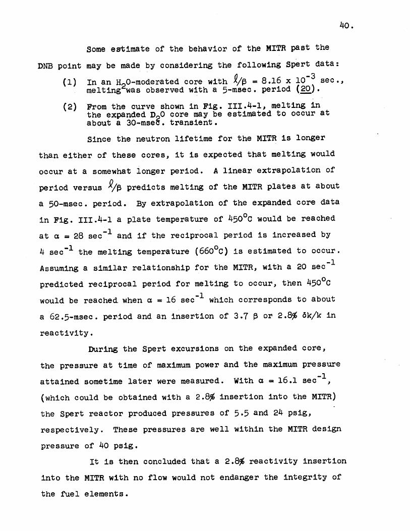
40.
Some estimate of the behavior of the MITR past the
DNB point may be made by considering the following Spert data:
(1) In an H2 0-moderated core with = 8.16 x 10⁻³ sec.,melting was observed with a 5-msec. period (20').
(2) From the curve shown in Fig. 111.4-1, melting inthe expanded D 0 core may be estimated to occur atabout a 30-mseg. transient.
Since the neutron lifetime for the MITR is longer
than either of these cores, it is expected that melting would
occur at a somewhat longer period. A linear extrapolation of
period versus /S predicts melting of the MITR plates at about
a 50-msec. period. By extrapolation of the expanded core data
in Fig. 111.4-1 a plate temperature of 45000 would be reached
at a = 28 sec and if the reciprocal period is increased by
4 sec~ the melting temperature (6600C) is estimated to occur.
Assuming a similar relationship for the MITR, with a 20 sec 1
predicted reciprocal period for melting to occur, then 450 0C
would be reached when a = 16 sec~ which corresponds to about
a 62.5-msec. period and an insertion of 3.7 P or 2.8% 6k/k in
reactivity.
During the Spert excursions on the expanded core,
the pressure at time of maximum power and the maximum pressure
attained sometime later were measured. With a = 16.1 sec -,
(which could be obtained with a 2.8% insertion into the MITR)
the Spert reactor produced pressures of 5.5 and 24 psig,
respectively. These pressures are well within the MITR design
pressure of 40 psig.
It is then concluded that a 2.8% reactivity insertion
into the MITR with no flow would not endanger the integrity of
the fuel elements.
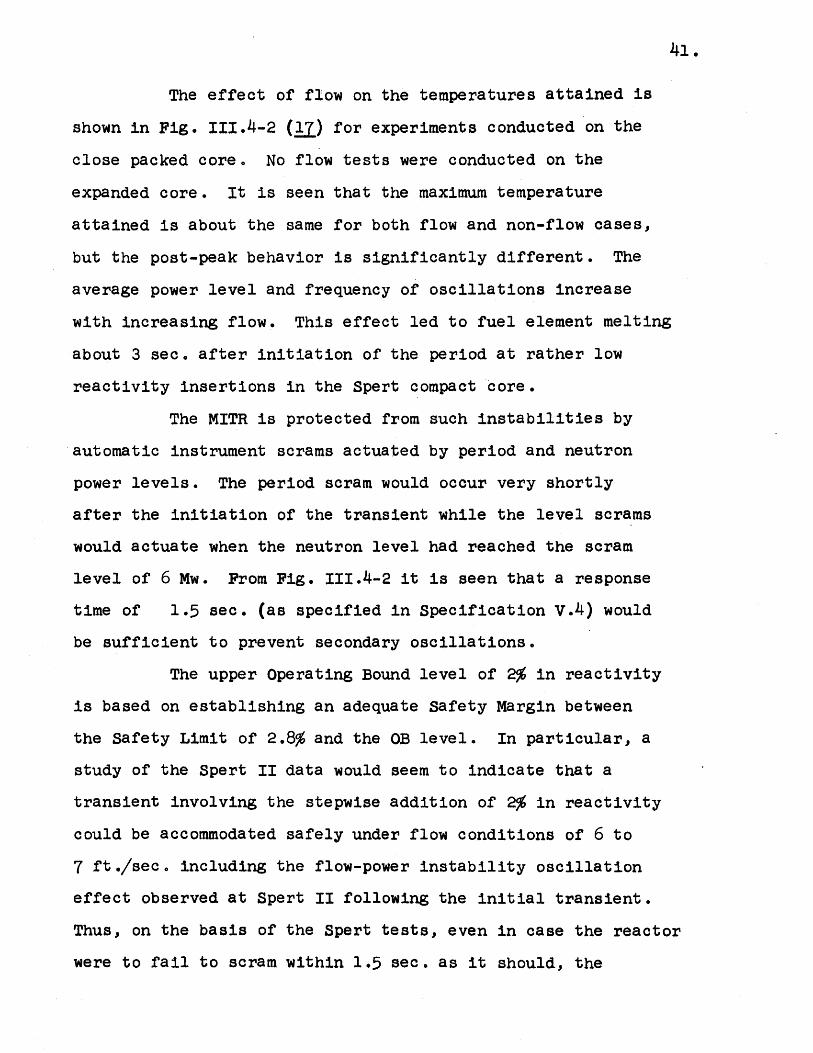
41.
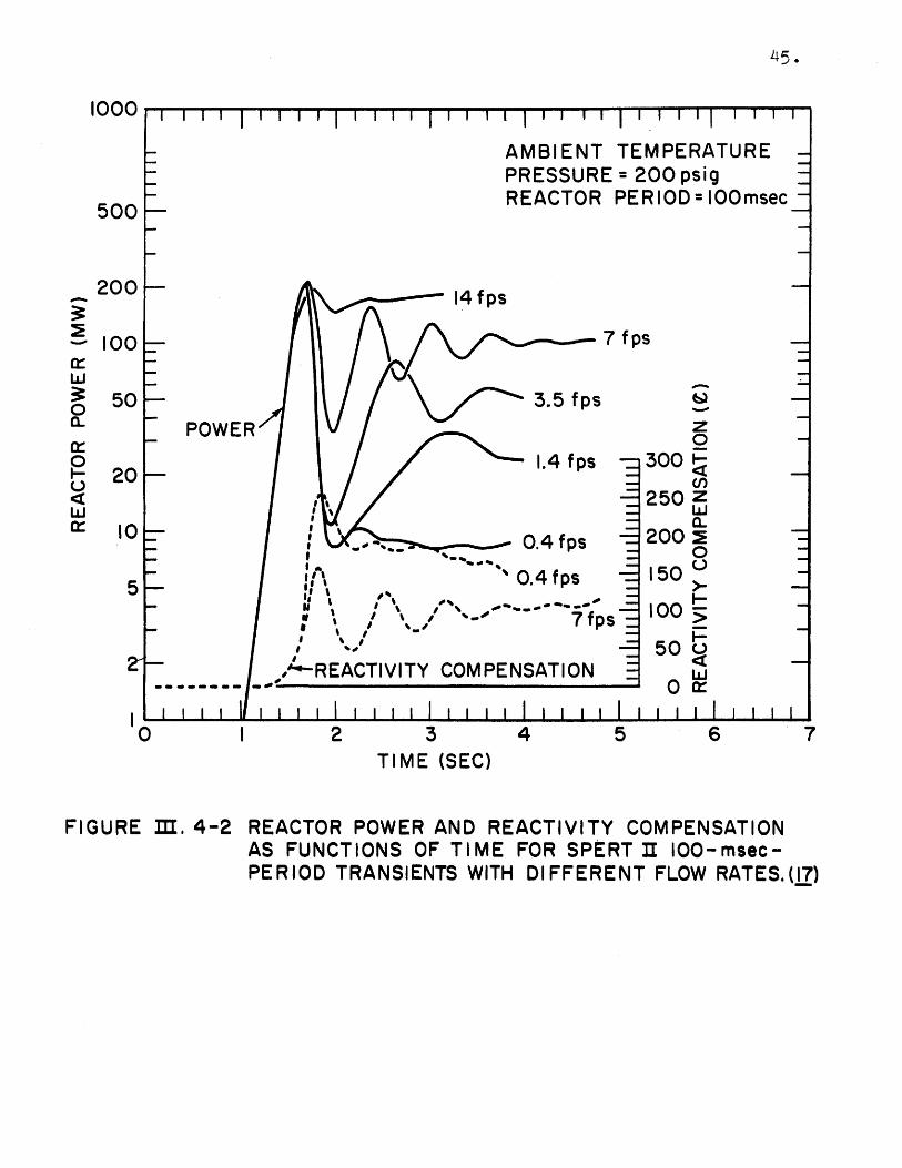
The effect of flow on the temperatures attained is
shown in Fig. 111.4-2 (l') for experiments conducted on the
close packed core. No flow tests were conducted on the
expanded core. It is seen that the maximum temperature
attained is about the same for both flow and non-flow cases,
but the post-peak behavior is significantly different. The
average power level and frequency of oscillations increase
with increasing flow. This effect led to fuel element melting
about 3 sec. after initiation of the period at rather low
reactivity insertions in the Spert compact core.
The MITR is protected from such instabilities by
automatic instrument scrams actuated by period and neutron
power levels. The period scram would occur very shortly
after the initiation of the transient while the level scrams
would actuate when the neutron level had reached the scram
level of 6 Mw. From Fig. 111.4-2 it is seen that a response
time of 1.5 sec. (as specified in Specification v.4) would
be sufficient to prevent secondary oscillations.
The upper Operating Bound level of 2% in reactivity
is based on establishing an adequate Safety Margin between
the Safety Limit of 2.8% and the OB level. In particular, a
study of the Spert II data would seem to indicate that a
transient involving the stepwise addition of 2% in reactivity
could be accommodated safely under flow conditions of 6 to
7 ft./sec. including the flow-power instability oscillation
effect observed at Spert II following the initial transient.
Thus, on the basis of the Spert tests, even in case the reactor
were to fail to scram within 1.5 sec. as it should, the
42.
transient and the subsequent oscillation should not result in
core damage.
The margin is also sufficient to accommodate even
the total withdrawal of the regulating rod within this margin.
The rod is the only one utilizing automatic control. While
it should be thrown out of automatic control by the electronic
circuitry, it is conceivable that it might not. The maximum
reactivity controllable by the regulating rod has been set at
0.75% (equal to P in this reactor). Normally its worth is
approximately 0.6%. It does not appear credible that there
would be any interaction between a change in reactivity caused
by an experiment and the operation of this regulating rod so
as to cause it to drive out. (The drive is a rack and pinion
system with a withdrawal rate of less than 1.0 in./sec.
corresponding to a reactivity effect of 2 x 10 6k/k/sec.)
In addition, the regulating rod is normally operated in its
mid range. The slow rate of withdrawal, the total worth of
the regulating rod, and the incredibility of an interaction
all indicate the conservatism of the margin from the viewpoint
of the operation of the regulating rod.
Assessment of Calculations
The calculations of the plate temperature attained
on step reactivity insertions is limited primarily by
predicition of behavior above the DNB point. The method
outlined above is consistent with the few cases where this
phenomenon was observed. Future measurements and/or
theoretical interpretation may improve the technical bases
of this specification.
43.
The effect of void coefficient on the maximum
temperature appears to be quite weak. The two D20 cores
studied at Spert which differed somewhat in void coefficient
exhibited almost identical behavior. Using a correlation of
H20 results (20) (which is applicable to D20 cores if
experimental pressures are used), the effect of decreasing
the void coefficient to 150 ms/liter increases the predicted
temperature at 2.8 6k/k by about 2500 if no steam blanketing
occurs. It is then concluded that a variation of 25% in the
MITR void coefficient would not affect this specification.
Therefore, 170 mp/liter is chosen as a conservative lower
limit for void coefficient.
In the expanded D20 core with = 0.1, a
temperature of 45000 on the plates would be reached with
a = 28 sec~ which corresponds to an insertion of 3.8 P or
2.9% 6k/k. The permissible reactivity insertion therefore
does not appear to vary significantly with variations in
neutron lifetimes typical of these D20 cores.
600
500
0%0
w
w
w
w
-
-i
wH
IL
300
I 1 111 1 I I 111i 1 1 l 1111111 Il
- MELTING RANGE OF 6061 ALUMINUM ALLOY
F- - EXPANDED CORE, ATMOSPHERIC (15)
e CLOSE-PACKED CORE, ATMOSPHERIC(16)
2001-
0
100|-
I I I 1 I iii1 I I I I I I I III
10 102
FIGURE II. 4-1
RECIPROCAL PERIOD (sec-')
MAXIMUM FUEL PLATE SURFACETEMPERATURE AS A FUNCTION OFRECIPROCAL PERIOD. (16)
14+.
400-
010-'
I I I I I I I II
1000
500
200
100
50
20
10
I I, I I I 11 1 1 1 1 1 1 1 1
0 I 2 3 4 5 6TIME (SEC)
FIGURE I. 4-2 REACTOR POWER AND REACTIVITY COMPENSATIONAS FUNCTIONS OF TIME FOR SPERT II IOO-msec-PERIOD TRANSIENTS WITH DIFFERENT FLOW RATES.(I7)
45.
a:-w0a-
0
w
7
46.
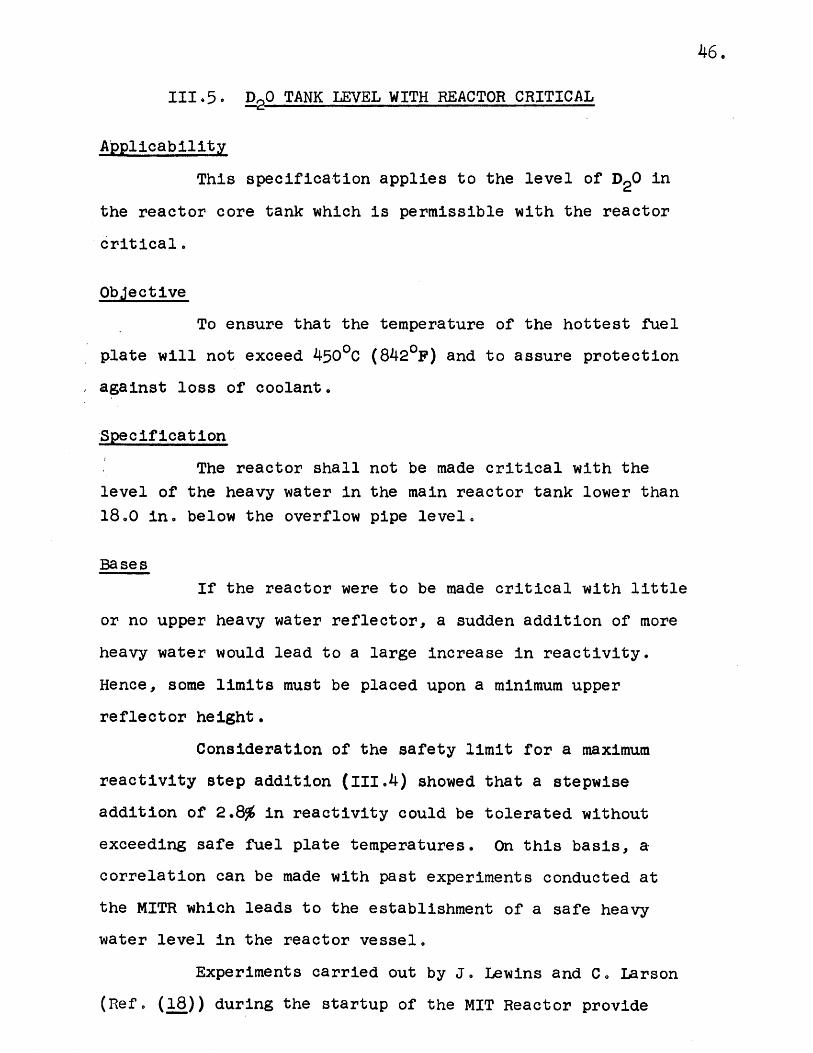
111.5. DPO TANK LEVEL WITH REACTOR CRITICAL
Applicability
This specification applies to the level of D20 in
the reactor core tank which is permissible with the reactor
critical.
Objective
To ensure that the temperature of the hottest fuel
plate will not exceed 4500C (8420F) and to assure protection
against loss of coolant.
Spec if icat ion
The reactor shall not be made critical with the
level of the heavy water in the main reactor tank lower than
18.0 in. below the overflow pipe level.
Bases
If the reactor were to be made critical with little
or no upper heavy water reflector, a sudden addition of more
heavy water would lead to a large increase in reactivity.
Hence, some limits must be placed upon a minimum upper
reflector height.
Consideration of the safety limit for a maximum
reactivity step addition (111.4) showed that a stepwise
addition of 2.8% in reactivity could be tolerated without
exceeding safe fuel plate temperatures. On this basis, a
correlation can be made with past experiments conducted at
the MITR which leads to the establishment of a safe heavy
water level in the reactor vessel.
Experiments carried out by J. Lewins and C. Larson
(Ref. (18)) during the startup of the MIT Reactor provide
47.
sufficient information to set this minimum allowable heightc
Reactivity worth of the top reflector was determined in a
series of measurements on a clean core with varied shim height,
a uniformly poisoned core, and a non-uniformly poisoned core.
The latter two cores were designed to represent operating
cores and other experiments have shown that they closely
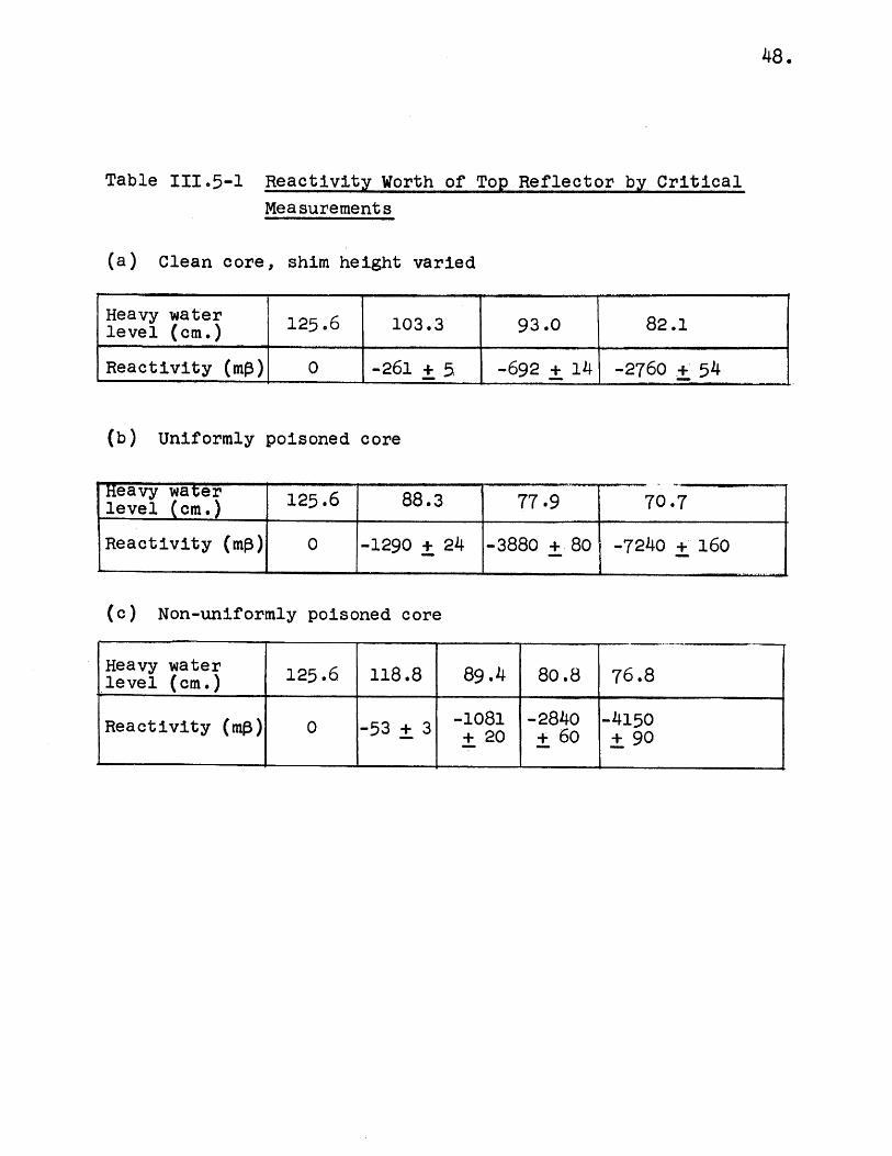
approximate the data. Table 111.5-1 from p. 101 of the thesis
report by C. Larson is reproduced here. This indicates quite
clearly that a reactivity loss by lowering the level from
overflow pipe level to 77.9 cm. (125.6 - 77.9 = 47.7 cm. loss
in height) results in a loss of reactivity of 3880 mp. In
this reactor, P is worth 0.75% reactivity and, therefore,
the loss of D20 height to 80 cm. is clearly conservative for
a Safety Limit. This is 45.5 cm. or 18.0 in. below the normal
level. The estimated errors shown in the table, based on
agreement of different sets of measurements and their
repeatability, indicate that the accuracy is sufficient to
assure the conservatism of the 18.0 in. figure.
The lower Operating Bound level of 5 in. below
the overflow pipe is purely arbitrary and based on the fact
that there is a tank level scram 4 in. below the overflow
pipe level. It could as well be 8 in. since little reactivity
change will occur by that time.
The level indicators on the tank ensure that if the
levels drop below the set points safety actions including
reactor scram will follow. Thus, a loss of coolant through a
pipe rupture will be detected early and measures can be put
into effect to minimize the consequences.
48.
Table 111.5-1 Reactivity Worth of Top Reflector by Critical
Measurements
(a) Clean core, shim height varied
Heavy water 125.6 103.3 93.0 82.1level (cm.) __________
Reactivity (mO) 0 -261 + 5 -692 + 14 -2760 + 54
(b) Uniformly poisoned core
leav (cme) 125.6 88.3 77.9 70.7
Reactivity (mp) 0 -1290 + 24 -3880 + 80 -7240 + 160
(c) Non-uniformly poisoned core
Heavy water 125.6 118.8 89.4 80.8 76.8level (cm.) (mp) _0 -53_3 ~___- _ - _150
Reactivity (nip) 0 -53 + 3 -1081 -284o -4150+20 + 60 +90o
49.
111.6. DO CONCENTRATION LIMIT
Applicability
This specification applies to the D2 gas concentration
in the helium gas cover blanket over the.D2 0 in the primary
system.
Objective
To prevent a flammable concentration of D2 gas in
the helium blanket.
Specification
The D2 concentration in the helium blanket shall not
exceed 6 volume percent.
Bases
Recombination of the dissociated D2 and 02 is
accomplished by continuously circulating the helium from above
the reactor core through a catalytic recombiner. The flow
through the recombiner is held at approximately two cubic
feet per minute, and the recombiner operates at a temperature
above seventy degrees centigrade as measured at the middle of
the reaction chamber.
In a thesis by John Nils Hanson, "Efficiency Study
of the MITR Catalytic Recombiner," (22) it is shown that the
recombination efficiency of the recombiner is 100% at 2 Mw
and will be 100% at 5 Mw. In the experiments at 2 Mw, the
recombiner was shut off for varying times up to 2 1/2 hours.
The largest concentration of D2 during these experiments was
found to be 1.448%.
50.
In a report, "Flammability of Deuterium in Oxygen-
Helium Mixtures," issued by the Explosives Research Center of
the Bureau of Mines (23), it is shown that the volume percent
of D2 needed for flammability is independent of the volume
percent of 02 from 4 to 30 percent 0 The data in this
report gives the flammable concentration of D2 at 2500 as
7.8' volume percent and 7.5 volume percent at 800C. Extrapolation
of these two points by a straight line approximation indicates
a flammable concentration of 6.87 volume percent at a temperature
of 20000. These results are conservative since ignition in the
tests was initiated at the base of the combustion tube.
The maximum temperature in the helium system will be
less than 2000C under all foreseeable circumstances; so it can
be concluded that combustion will not occur if the D2
concentration is kept less than 6 volume percent.
The same report shows that even with deuterium-air
mixtures of 30% D2 plus 70% air the peak pressure reached in a
mixture ignited in a 2-ft. sphere at 250C at one atmosphere
initial pressure was approximately 83 psig. This would seem
to indicate that even in event of combustion of concentrations
of deuterium far beyond that envisioned the pressures reached
are not sufficiently high to rupture the primary containment
in the region cf the reactor vessel or major piping. This
statement, while not amenable to direct proof, appears well-
supported since the 2-ft .-diameter sphere represents a larger
wall-to-wall distance than any vital section of the primary
system. The most likely region for failure is the D20 storage
tank located in the basement. A rupture disk is located on
51.
this tank and even the total loss of this tank by an excessive
pressure would not seriously harm the rest of the system.
Therefore, it is concluded that this parameter, even in the
extreme, may not pose a safety limit of any sort; although
proof is not available.
The design pressure of the system is 40 psig,
utilizing ASME Unfired Pressure Vessel conditions. Pressure
surges of the order of twice design pressure are well within
the capabilities which the system can withstand.
The accuracy of the experiments described in Ref.
(23) is best indicated by a brief discussion of the data.
All experimental mixtures which were flammable for the 80 0 c
initial temperature tests were within 0.3-0.5 volume percent
above the 7.5% deuterium mixture limit and those which were
not flammable were within a similar band below the limit.
Similar results are reported for the 250C experiments. Thus,
the set of experiments was carried out in such a way as to
define quite accurately the limits of the region of
flammability as a function of volume percent deuterium gas
with from 60 to 90% helium present and the balance oxygen.
The experiments were carried out at pressures of 0.5, 1.0,
and 2.0 atmospheres and appear to be independent of pressure
within that region. Since these experiments cover exactly
the range of conditions and gaseous mixtures of interest here,
they should be completely applicable.
The upper Operating Bound level for deuterium
concentration in the helium cover gas was established at 4%
primarily in order to provide a reasonable margin between
52.
the Safety Limit and the OB level. In addition, it was
necessary to set it high enough to ensure that too frequent
audits were not necessary.
53.
IV. SAFE OPERATING CONDITIONS
These conditions assure that Safety Limits are
being properly observed and that vital equipment
functions correctly.
54.
IV.1. EMERGENCY COOLING REQUIREMENTS
Applicability
This specification applies to the emergency cooling
system including the emergency cooling tank, valves, piping,
transfer pumps, standby transfer pump, and fuel element spray
heads.
Objective
To ensure that sufficient time is available for
taking additional steps to cool the fuel elements subsequent
to a loss of D20 from the main reactor tank.
Specification
The emergency cooling tank shall be capable of
providing for operation at power levels above 1 Mw a minimum
of 20 minutes of emergency cooling flow over the fuel elements
with a minimum total flow rate of 4.5 gal./min.
Bases
As is shown below, a total flow rate of 4.5 gal./min.
from the D20 emergency cooling system is more than adequate to
remove the decay heat of the hottest fuel element immediately
following the loss of D20 from the core tank. This assumes
the reactor has scrammed, either from the low level tank scram,
or from the loss of over 13 P associated with the loss of the
moderator. Since the decay heat is a decreasing function with
time, this flow rate is also more than adequate for cooling
the core for times longer than 20 minutes. (The capacity of
the emergency cooling tank is 175 gallons.)
55.
1. Cooling of total core. Consider first the
ability of the present emergency coolant to remove the decay
heat from the core. Allow this coolant to completely
evaporate. Assuming that the initial temperature in the
coolant tank is 250C, then the enthalpy change from liquid
water to saturated steam is 404 x 103 kg-cal.
The decay heat, P, from fissions of U235 is given
(24) as a fraction of the operating power, P9, as:
= 6.22 x 10⁻² (t-0. 2 - (T+t)-0.2P0
where: t = decay time (sec.), and
T = irradiation time (sec.).
During a period - after shutdown the total heat
produced is:
Q = 6.22 x 10⁻²P (t-0.2- (T+t) 0.2)dt
0
= 7.78 x 10⁻²P (T - (T+ ) + T ' )Mw-sec.
If, to be conservative, the irradiation time is taken
to be infinite, then Q is 27.1 x 10³ kg-cal. when P is 5 Mw.
Thus the capacity of the emergency coolant is more
than adequate.
2. Cooling of center element. The decay heat of an
individual element will depend on the operating power of that
element. The less elements in the core the higher the
individual element power must be. Also, the power generated
in the element must be increased by heating from the gamma
rays produced in surrounding elements.
Let F be the energy production rate for gamma's and
F be the production rate for beta's in a fuel rod.
(1) Based on calculations made at Harwell (25) forsimilar fuel elements, we assume that lu% ofthe beta production is absorbed in the elementand 12% of the gamma's.
(2) Assume production rates are equal, as is statedon pp. 7-15 of Ref. (24).
FY = F = F .
The total energy production in an element is then:
2F = P , and F = .
The total energy absorbed from the energy producedwithin the element is:
F + 0.12 F= 1.12 F = 1.2 P = o.56 P
The rest of the energy,0.44 Pescapes to surroundingelements.
(3) If the surrounding elements are assumed to produceequal power and are considered line sources, thenthe power reaching the central element from aneighboring element is 0.44 P (3/r) where r is ininches (1/r variation for line sources).
(4) Finally, assume 25% of the incident gamma radiationis absorbed. Then a surroundin element contributes0.25 x 0.44 P (3/r) = 0.11 (3/r) to the energyabsorbed in an element. Considering all the elementssurrounding the central element, then Pa, the totalabsorbed energy,
N 3Pa =0.56 P + 0.11 P r
orN
P =MP =(0.56+0.11 -)Pa 7 _ r.
where Ni is the number of elements in the ring.
For a 19-element core
My = 0.56 + 0.11 (2.82 + 2.72)
= 1.17
56.
57.
and for a 24-element core
Mf = 0 .56 + 0.11 (2.82 + 2.72 + 0.864)
= 1.26 .
In the 5 Mw Report (7), a 19-element core was
considered with element power limited to 500 kw from reactivity
considerations. Taking the burnup of this element to be
55 MWD (which is the maximum burnup to present), the heat
absorption one second after shutdown including gamma ray
absorption will be 484 kg-cal./min.
The flow rate through this element during the 20
min. of emergency cooling will be 1 2 gals./min. = 1.742
kg/min. Allowing this water to change to saturated steam
would remove 1063 kg-cal./min., more than is being generated
in the element.
There are two methods of providing this cooling
after the 20 min. of emergency cooling have expired, both
utilizing the emergency cooling tank. In the first method
the transfer pump (backed up by the standby transfer pump
in case of electrical failure or other failures of the
transfer pump) is used to supply D20 to the emergency cooling
tank. Suction can be taken from any part of the D20 system
or from the floor of the equipment room if the spillage has
occurred there. In the second method light water is supplied
to the emergency cooling tank from a city water supply
through a quick-connect fitting. This second method is thus
independent of any conceivable D20 system failure causing
loss of coolant from the core tank.
58.
Since both methods involve relatively simple
procedures and since either ensures a readily available
adequate source of decay heat coolant, a 20-min. supply of
emergency cooling water provides adequate protection to the
core for this eventuality.
Since it has been shown on p. 692 of Ref. (26)
that metal conduction to structural members combined with
natural convective gas cooling is adequate for removing
decay heat at power levels below 1 Mw, this specification
applies only for power levels in excess of this amount.
The calculations in (24) and (25) provide adequate
allowances for error and for spray variability within the
element. No allowance has been taken for conduction of heat
into the fuel element side plates and end boxes and thence
into other structural members which p. 692 of Ref. (26)
indicates is an important factor. No allowance is made for
convective heat loss by gas or steam circulation. Omission
of these factors is conservative.
IV.2. BUILDING CONTAINMENT AIR LEAK RATE
Applicability
This specification applies to the reactor building
containment air leakage.
Objective
To ensure against the release of airborne radio-
active effluent from the building in quantities endangering
the general public in event of any accident within the
building.
Specification
The air leak rate of the building containment shall
be less than 2 percent of the containment air volume per day
at 2 psig over-pressure when the ventilation dampers are
closed. Full containment will be a requirement to permit
reactor startup. An interlock shall be provided to assure
that rods can only be withdrawn if no major containment leaks
exist.
Bases
The possibility of the release of fission products
from fuel elements has been discussed in the January 1956
MIT "Final Hazards Report," Appendix C; the October 7, 1960,
(27) "Two Megawatt Report," Addendum to Appendix C (28); and
the November 5, 1963, "Five Megawatt Report," changes to
Appendix C. The conclusion reached is that the fission
product release due to a fuel meltdown is an incredible
accident.
As a justification for the leak rate specification
of less than 2 percent of the containment volume per day at
59.
60.
2 psig over-pressure, a new evaluation has been made of the
maximum exposure that could occur in the incredible event of
fuel melt and fission product release.
Two mechanisms for the incredible accident which
might melt fuel can be imagined:
(1) A sudden insertion of reactivity of such a largeamount that the inherent shutdown mechanism of thevoid coefficient will not prevent fuel elementmeltdown.
(2) A sudden loss of all D 0 in the core during operationat 5 Mw with the emergency cooling system foundinoperative in any form so that it will not preventfuel melt due to fission product decay heating.
In the first case, the limitations on reactivity
available in the core preclude the possibility of the
reactivity insertion causing fuel meltdown. In the second
case, only if the pipe from the emergency cooling tank were
suddenly plugged or sheared at the time of the D20 loss could
the emergency cooling system be made inoperative. Even if
the emergency cooling system were inoperative, it is not
clear that the connecting aluminum adaptors will not conduct
enough heat away from the elements to reduce the peak of the
slowly rising temperatures even in the hottest element below
the melting point of aluminum. Since both of these
accidents are believed to be incredible and the second
accident might not lead to fission product release, the first
accident is assumed, therefore, to give a more conservative
(largest) estimate of the largest concentration of fission
products in the atmosphere of the containment shell.
The calculations presented in the 12/26/57 Addendum
to Appendix B and C of the Hazards Report (MIT-5007) (a), as
61.
submitted to the AEC, shows that under very conservative
assumptions the maximum possible exposure to radiation in one
hour due to leakage of fission products out of the containment
shell at the maximum permissible leak rate will be less than
1750 rem to the thyroid, 6.85 R total external P dose, and
0.6 mr gamma dose, after operation of the reactor at 1 Mw
and complete fuel melting. Conservative, but more realistic,
assumptions can be made which will reduce the magnitude of
these calculated values.
First, experience with reactivity transients which
lead to fuel melting would indicate that the core will not
be completely melted. In the results of the SL-l release,
p. 680 of Ref. (26), it was found that 40% of the fission
product inventory was involved in the melted fuel and,
further, only 5 to 10% of the total fission product inventory
escaped from the vessel. Thus it will be assumed that only
40% of the total fission product inventory is contained in
the melted fuel plates, rather than 100% as used previously.
It should be noted that the effects of after-heat in the MITR
are much smaller than those in most power reactor cores
being considered today and, therefore, the SL-l experience is
quite comparable to the hypothesized incredible accident being
considered here. In addition, the fuel type is similar.
Second, the operating cylce of the MIT Reactor
consists of approximately 100 hours of continuous operation
and then a shutdown for the remainder of the week. Therefore,
the Il31 concentration does not reach the saturated
equilibrium value, "A ". At the end of a long series of
weekly 107-hr. irradiations the I 3 activity is 0.7 AC or
70% of the saturated activity.
Third, in order for any of the building contents to
escape, it is necessary for the pressure inside the building
to rise above atmospheric pressure. Neither of the two
accidents discussed above will lead directly to a significant
building pressure rise. The reactor core is operated at a
few inches of water pressure above atmospheric pressure, and
a rupture of the reactor vessel will not release a large
amount of energy to the atmosphere in the containment, in
contrast to a large energy stored in a pressurized power
reactor. Therefore, the possible increase in building
pressure can only come from changes in the external atmos-
pheric pressure after the containment is sealed. In the
previous calculation it was assumed that a differential
pressure of 1 psi above atmospheric could occur. However,
such large changes in differential pressure have only been
recorded in rare cases and occur over long time periods (more
than a day). Since the exposure is calculated at the closest
point which will be evacuated in a short time, it is
reasonable to consider only short period changes in
atmospheric pressure. According to the Boston Weather Bureau,
a thunderstorm nose creates the shortest time pressure
variations. The most marked example of such a pressure change
since 1872 through 1946 occurred on June 8, 1946, when the
pressure rose 0.19 in. of Hg, and then dropped 0.24 in. of Hg
in a period of 1 1/2 hours. If the building had been sealed,
the vacuum breakers would have opened during the pressure
62.
63.
rise and the differential pressure would have risen to 0.24 in.
of Hg during the atmospheric pressure drop. This occurrence
and similar pressure drops recorded at the MITR indicate that
such decreases are approximately linear with time. The average
pressure differential for the worst case would then be about
half maximum or 0.12 in. of Hg. It is then conservative to
assume a maximum average differential pressure of 0.16 in. of
Hg during the 1-hour exposure time.
The combination of these three items leads to a
factor of:
( ) (1 ) ) x (45.7,U.7Fraction Cycle Short time
of core operation pressuremelt rise
by which the previous calculation of the thyroid dose should
be reduced. (Note that the previous calculated dose was
reported in units of rep with a conversion factor of 100
ergs/gm which is now designated as Rad, Rem = RBE x rad.
However, for this case, RBE = 1.0 according to NBS Handbook
69. Hence, the previous value of 1750 is taken to be rem.)
After operation of the reactor at 5 Mw the
calculated dose in the incredible event of a reactivity
excursion leading to the release of fission products due to
fuel elements melting and to the exposure at the boundary of
the exclusion area to the maximum permissible leakage becomes:
D = = 191 rem,
to the thyroid due to I1 31. Even if the reactor were to be
operated on a continuous 24 hour a day schedule, the dose
would not be greater than:
64.
D = = 273 rem
The external dose to a person standing in the leakage
cloud due to beta or 7 radiation from the cloud is calculated by
assuming a continuous operation of the reactor for 180 days at
5 Mw prior to the fuel melting, and the above assumption
concerning the fraction of the core melted and atmospheric
pressure rise. By using the previous calculations, the external
p dose becomes:
D = 56.8) = 1.07 rad in 1 hr.;
and the 7 dose from the cloud at the maximum dose point becomes:
D7 = 50.565) = 0.09 mrad in 1 hr.7(45,T)(0-T)
Summary. The dosage to critical organs from inhalation
of all other radioactive fission products is much less than from
iodine. It is concluded, therefore, that the gas-tight building
surrounding the MIT Reactor provides adequate protection to
persons outside the building against exposure due to fission
products or inhalation of fission products even if fuel elements
of the reactor should melt, an accident considered to be itself
incredible.
An interlock must be satisfied requiring a minimum
0.10 in. water pressure differential (negative) in the building
before a reactor startup can be conducted. This condition
ensures that the building containment is not grossly violated
at the time of startup. This same system shall provide a
continuing alarm, if during operation the pressure differential
is not satisfied.
65.
IV.3. REACTOR CONTROL INSTRUMENTATION
Applibability'
This specification applies to that instrumentation
necessary for reactor control.
Objective
To insure that the operator has sufficient
indication of power level, neutron flux level, D2 0 flow,
reactor tank level, and reactor outlet temperature.
Specification
A. The reactor shall not be brought critical or operated
unless the following instrumentation is in operation:
(1) 2 neutron level channels
(2) 1 period channel
(3) Main reactor tank D20 level indicator.
B. The reactor will not be operated above 200 kw unless
there is indication of the following parameters in
addition:
(1) Reactor D20 outlet temperature
(2) Main D20 flow.
C. Emergency power to operate the instruments indicated
under IV.3-Al,A2,A3, and BI above and also those
specified under IV.4 shall be made available for atleast one hour following a loss of normal power to thefacility.
Bases
The neutron level channels and period channel
provide indications of power level and change in power
level during the approach to criticality and at low power
levels. These instruments are therefore required at all power
66.
levels including subcritical operation. At power levels above
200 kw there is an additional need for flow and outlet
temperature information to insure that the system is being
operated within Operating Bound levels.
In practice, low power physics tests are usually
done between 2 kw and 8 kw. To establish 200 kw as an upper
limit for this type of operation, the calculated temperature
rise as a function of time in the main tank with no main D20
flow is shown below.
200 kw x 3414 Btu F0 .41 hr.200k x xf Bu- 9 F0 m4. C o/i
9.16 gal )x 475 gal
Using this temperature rise and an intial temperature of 25 0C,
it would require approximately 50 min. for bulk boiling to be
reached. Since this mode of operation will be used only for
low power physics tests, the 50 min. provides ample time for
observations and subsequent shutdown.
As the temperature of the coolant is raised from
250C to 1000C, the existing negative temperature coefficient
will result in somewhat over 3.5 P in negative reactivity
being added. Since no reactivity changes during low power
physics tests will exceed a small fraction of P, the tempera-
ture of the bulk D20 will rise only a few degrees before a
low equilibrium power level is established. Thus, even in the
event no shutdown occurs, the reactor is self-protecting.
At all times the MITR has present in the core
valving which permits a convective flow within the primary
tank in the event of loss of flow. This valving would permit
convective flow in the less than 200 kw operation. In addition,
work at Harwell (30) has shown that convective flow is induced
within a core similar to the MITR core even if no such valving
exists.
While the use of emergency power is probably not
required in this reactor since loss of power automatically
scrams the reactor and since coolant will still cover the core
and melting will not ensue, none the less, the knowledge
supplied to the operator that the reactor is properly secured
and protected will insure an orderly procedure in all such
cases. The choice of a minimum of one hour is based on
providing reactor information during the period following
scram and far enough beyond the emergency cooling cycle
operation to insure that the core is receiving adequate
subsequent cooling.
67.
68.
Iv.4. REQUIRED RADIATION MONITORS
Apbplicability'
This specification applies to the radiation monitors
needed to prevent release of radiation to the atmosphere above
levels allowed under lOCFR20.
Objective
To ensure that operation of the MITR does not subject
the public or MIT personnel to amounts of radiation above that
allowed by lOCFR20.
Specification
1. During periods when the reactor is operated or ventilation
exhausted to the environment, a radiation monitor, which
indicates in the control room, shall be operable in each of the
following areas:
(a) A monitor or monitorsin the ventilation exhaust
header capable of detecting particulate and gaseous
activity.
(b) Ventilation exhaust stack. (Stack count rate
monitor and/or stack area monitor.)
2. A secondary system water monitor, which indicates in the
control room, will be in operation whenever secondary
cooling water is being circulated between the reactor
building basement and the cooling towers.
3. At least one floor monitor shall be in operation at all
times.
Bases
A negative pressure of 0.2 in. of H20 is maintained
in the MITR containment shell so that any air leakage at
fittings will be into the containment shell. All ventilation
69.
enters and exits through ventilation headers. Both the inlet
and outlet headers are fitted with filters, "Butterfly"
dampers, emergency dampers, and fans. The monitors located
in the ventilation exhaust main header are used to supply
trip signals to seal the building and prevent the escape of
radioactive effluents. The monitors located in the exhaust
stack are to determine whether any high level release has
actually taken place.
The plenum gaseous monitor is primarily used for
detecting radioactive gaseous effluents. The particulate
monitors will detect radioactive gaseous effluents such as
Argon 41 with a decreased efficiency. Thus, if the gaseous
monitor is not operating or being repaired, the trip point on
the particulate monitor can be lowered to provide adequate
protection. The two monitors in the ventilation exhaust stack
back up one another and, hence, adequate protection will still
be present if one monitor should fail. There is a detailed
analysis of the MITR radioactive effluents in the 5 Mw Report
of November 5, 1963.
The secondary water monitor surveys the water
which passes through the cooling towers for the presence of
radiation. It cannot detect tritium, but would detect the
presence of N16 which would accompany any leakage of heavy
water through the heat exchanger tubes into the light water.
Therefore, it would immediately indicate a D2 0-H 2 0 leak and
the system would be shut down. During shutdown operations,
for instance over weekends, the radioactive level in the H20
would be considerably lower in the event of a leak, but the
70.
background is also lower and Na in the leakage D20 would
permit detection of the leak.
At least one operating floor monitor is needed to
insure that the general radiation levels in the occupied
area around the reactor are within the limiting values
established by 10CFR20.
71.
IV.5. VARIABLE EXCESS REACTIVITY AND SHUTDOWN MARGIN
Applicability
This specification establishes the permissible variable
excess reactivity and the required control rod worths.
Objective
To enable the reactor to be adequately shut down
under all conditions.
Specification
1. Five shim rods shall be in operating condition and the main
reactor tank at overflow before bringing the reactor to a
critical condition.
2. The total variable excess reactivity above cold Xe free
critical shall be less than the worth of the four least
reactive shim rods.
3. An absorbing element shall be removed from the core for
maintenance only if the core shall be left subcritical
by at least the worth of the most reactive remaining shimrod.
4. The reactivity worth of the regulating rod connected to
the automatic control system shall be less than 0.75% 6k/k.
5. The reactivity worth of the limited dump of the top reflector
shall be greater than the reactivity effect of the mostreactive shim rod.
Definitions
1. The "cold Xenon free critical" MIT reactor is defined as
a critical configuration in which:
(a) The average D20 temperature in the core is 100C.
(b) No fission product Xenon exists in the reactor.
(c) The reactor is loaded for the beginning of an operatingperiod.
72.
(d) Variable reactivity effects such as sample changeswhich occur during normal operation shall be in thestate in which they have the maximum positive reactivity.
2. Variable reactivity refers to the changes which may occur or
vary during operation. It will include Xenon, fuel burnup
(for one or more operating cycles), sample changes made in
operation, changes in experiments during operation, etc.
Bases
Limiting the total excess reactivity to less than the
worth of the four least reactive shim rods and with only five
rods operating allows one rod to fail to drop while still
completely shutting the reactor down.
Due to Xenon buildup after shutdown from equilibrium
conditions, at least one more rod could be held up temporarily
(up to 32 hrs at 5 Mw) and still hold the reactor subcritical.
In the six years of operation of the MITR, no rod
has failed to drop on a scram signal. It is then considered
unlikely that at least four rods out of five would not be
inserted. In normal operation, six control rods would be in
operation and only four rods out of six would have to drop.
The specification on removal of an absorbing element
provides that the stuck rod criterion will always be met, even
when one rod is removed for repair. Thus the reactor still
would not go critical on the removal of a second element.
Since the movement of the regulating rod is governed
by the automatic control system, a possibility exists of its
accidental withdrawal. Its worth is therefore made a part of
this Technical Specification. Although it is not deemed
credible, the entire limiting worth of this regulating rod
added to the reactivity worth allowed at the Qperating Bound
73.
level (that amount which might be added by the credible failure
or malfunction of any experiment or component or any set of
circumstances which could credibly couple two or more components
or experiments) still would not exceed the Safety Limit of 2.8%.
As a further precaution, at least an additional shim
rod worth would be available from the limited dump of the D2 0
reflector. This provides at least the equivalent of the stuck
rod criterion safety margin in a completely independent back-up
shutdown method.
As a general philosophical basis, the following stuck
rod criterion is complied with at this reactor: "It should be
impossible for a reactor to be made critical in its most reactive
situation on the withdrawal of a single rod. Conversely, it
should always be possible to shut down the reactor with one
rod stuck in its outermost position. If it is possible that
rods or mechanisms might interact so that several could be
stuck in the out position, then the number of rods included
in the stuck rod criterion should be increased accordingly."
(26, p. 677)
74.
IV06. FUEL ELEMENT' DESIGN LIMITATIONS
Applicability
This specification applies to design standards for
fuel elements.
Objective
To ensure that the design of any fuel elements used
in the reactor will provide adequate containment for the
fission fragments, adequate and rapid heat transfer from the
fuel through the clad to the water and adequate cooling of the
element, and adequate boiling shutdown in event of a severe
reactivity accident,
Specification
1. The fuel-bearing sections of the core shall consist of
thin tubes or plates, each of which has a fuel section
composed of uranium and aluminum clad by a layer of
aluminum metal of not more than 0.025 in. thickness or
less than 0.015 in.
2. The design of any element shall be such that in normal
operation no bulk boiling shall occur in this or any
other element in the core due to neutron flux peaking
or D20 flow distribution when the element is placed in
any position in the core. This fact shall be ascertained
by appropriate tests.
3. (a) Element designs shall be tested by prototype tests
of dummy elements to see that they do not deform,
disassemble or give indications of undue vibration
at a flow rate of at least 12 ft. per second.
(b) The element shall be mechanically locked in position
in the reactor core during periods when the reactor
is critical.
75.
4. Any element design -shall provide a minimum core averaged
negative void coefficient of 170 mp/liter of void in the
active section of the element.
5. The design of any element shall be such that in a 19-
element core operated normally (i.e., 19 elements or more
and with shim rods banked) the calculated maximum fuel
element plate temperature shall not exceed 450 0C in event
that any of the Safety Limits is reached.
6. All elements shall be so designed that, in a corecontaining 19 to 30 elements, they will operate in a stable
flow regime within the limits set by the Technical
Specifications on reactor power and outlet temperature.
Bases
Ref. (8) ("Process System Requirements of the MIT
Reactor at Five Megawatts," W. R. Devoto) provides the basic
equations and methods, and outlines the experiments upon which
the design will be based.
The minimum clad thickness is based upon a series
of MTR tests on elements with similar clad. These tests show
that clad thicknesses of 5 or 10 mils permitted some fission
products to be emitted. They also showed that 15-mil clad
was completely adequate from the normal operating fission
product retention viewpoint. Ref. (26), p. 672, shows that
a thick clad increases the delay time for heat removal in
event of a fast transient. Therefore, the clad should be as
thin as possible while still remaining compatible with fission
product retention requirements.
The selection of a no bulk boiling criterion assures
that there will be no major fluctuations in reactor power due
to the evolution and collapse of voids in the fuel and its
76.
feedback effects on reactivity. Also, as shown in III.1,
111.2, and 111.3, it has the effect of establishing a
maximum heat flux per plate. This corresponds according to
Ref. (7), as modified by the considerations of III.1, to the
equation:
PPMAX = 7.82 x 10⁻³ ' 1T . (IiI.1-4a)
Any fuel element should be designed for structural
integrity and stability including possible vibrational effects.
The design should assure that they will remain rigidly in
place. Thus one specification requires that new types of
elements be hydraulically tested at conditions more severe
than normally encountered. The maximum flow velocity expected
during 5 Mw operation is approximately 8 ft./sec.
As indicated in 111.4, the principal shutdown
mechanism which would terminate a severe nuclear transient is
boiling. Thus the quantity of reactivity worth which can be
obtained to shut down the reactor in such an event is an
important part of the core transient behavior. Thus a
specification of the void coefficient and total available
void volume in each element is important. The choice of
this particular specification insures that future fuel
elements will comply with the Safety Limit set forth in III.4.
The ultimate safety goal of fuel element design
remains to ensure that the 450 0C plate surface temperature
is not exceeded. This value was chosen as indicated in the
Introduction because aluminum melts at about 6600C and its
strength deteriorates significantly with temperatures above
77.
450 0 C. Harwell reports that they have observed severe
blistering of irradiated fuel under prolonged exposures to
temperatures of 550 C with the onset of the phenomenon at
about 5000C (25).
The design of any fuel element must also ensure
that no flow instabilities or burnout can occur in thermal-
hydraulic regimes which could conceivably be reached in
normal or abnormal operation. Therefore, a specification
has been set up so as to make the design and characteristics
of any new fuel elements be self-consistent with those now
in use.
The specifications set forth above make the thermal,
hydraulic, and nuclear characteristics of any allowable fuel
element design consistent with the Safety Limits described
in these Specifications. Therefore, the utilization of any
fuel element complying with these Specifications does not
constitute an unreviewed safety problem.
78.
IV .7. FUEL ELEMENT HANDLING AND STORAGE'
Applicability
This specification applies to the operations of
storing and handling fuel elements.
Objective
To ensure that fuel elements will be handled at all
times in a manner to protect the health and safety of the
reactor personnel involved and the public and to safeguard
the elements.
Specification
1. Fresh fuel elements shall be stored in any of the
following locations:
(a) In the reactor.
(b) Within the dry storage holes on the reactor top.
(c) In two approved storage vaults in the buildingadjacent to the containment building.
(d) Temporarily in rooms or sealed-off areas whichcan be locked for storage during experimentsinvolving fuel.
2. Irradiated fuel element assemblies shall be stored in
any of the following locations:
(a) In the reactor.
(b) In the dry storage holes on the reactor top.
(c) In the fuel storage tank in the basement of thereactor building.
(d) In the fuel element transfer flask or otherproper shield within the controlled area.
3. Handling of fuel elements:
Only one fuel element at a time shall be moved in or
out of the reactor core. Not more than six of the
MITR fuel elements shall be outside of the storage
areas as designated in Items la,b,c and 2a,b,c, except
79.
during the processes of receiving or shipping fuel from
the site in approved containers. Records of-fuel
element transfers shall be maintained. Prior to trans-
fering irradiated fuel from the reactor vessel to the
transfer flask, the reactor shall have been shut down
from power operation above 200 kw for a minimum period
of twelve hours.
Bases
The principal problem in regard to fresh fuel elements
is that of accidental criticality. The locations specified in
la,b,c and 2a,b,c provide for complete criticality control.
The reactor itself is of course shielded and appropriate
written procedures assure that it is loaded properly. The
dry storage holes in the reactor top are separate pipes poured
in the concrete shielding and thus are isolated from one
another neutronically. The fresh fuel storage vault and the
spent fuel storage pit both have carefully designed geometric
arrays to assure that criticality will not occur. The
specification of no more than six elements outside of the
designated storage areas of la,b,c and 2a,b,c assures that
no criticality will occur elsewhere.
The chief additional problems with spent fuel are
those of shielding personnel from the emitted fission
product gamma rays and preventing melting from after-heat.
The shielding requirement is met by utilizing a shielded
transfer flask for movements and temporary storage and more
permanent shielding as indicated in 2a,b,c,d. The require-
ment to prevent melting is met by specifying that 12 hours
elapse between reactor shutdown and removal of the element
80.
from the core. Harwell (2) has shown by experiment that an
element very similar to that used in the MITR and operated at
a power of 500 kw/element will reach a maximum plate
temperature of ~4500C if removed into non-circulating dry
storage after 5 hours incore cooling and 360 0C after 12 hours
incore cooling. Since the 500 kw element corresponds to the
highest power element conceivable in the MITR at 5 Mw(t) this
is deemed to provide sufficient conservatism.
81.
iv.8 LIMITING CORE OPERATING CONDITIONS
Applicability
This specification applies to core conditions during
operation of the MITR at power levels above 200 kw.
Objective
To ensure that the core is operated in a manner
consistent with the assumptions used to evaluate the Safety
Limits.
Specification
In addition to items stated elsewhere in these
Specifications, the reactor shall not be operated at powerlevels greater than 200 kw unless:
1. All positions in the reactor plenum head are filled
with either a sample assembly or a fuel element and thereare no less than 19 fuel elements in the core.
2. Each shim control rod is within 4.0 inches of a banked(average shim rod height) position.
Bases
The Safety Limits in Section III were derived by
assuming that the D20 flow is evenly distributed between
fuel elements. There remains the possibility that the flow
is not distributed evenly through the elements or that the
power generation for a given element or elements varies more
than allowed for in the calculations. There are two
limiting conditions. One occurs when all the positions in
the core contain fuel elements (30 elements) and the D20 flow
Operating Bound is set at 1800 gpm resulting in the minimum
82.
flow per element. The other limit occurs when the number of
elements is reduced until the peak power in the central
element exceeds that which was used for the derivation of the
Safety Limit. The calculations were made for 19-element and
30-element cases; hence, the core should not be operated with
less than 19 elements unless the calculations are again
reviewed.
Further, the Safety Limit evaluations included the
effect of banked shim rod height changes but unbalanced shim
rod configurations might lead to heigher power per element
conditions than have been calculated; hence, the shim rods
should be effectively banked within about 10%. Since the
average differential reactivity worth of a single shim rod is
approximately 1/6 p/inch, a deviation of + 4.0 in. for a
single rod will amount to about 2/3 p, or less than prompt
critical. Since the total core operational excess reactivity
is about 10 P, the effect of a single rod deviation of 4 in.
will be less than 10% of the total banked shim worth.
83.
V. OPERATIONAL SURVEILLANCE REQUIREMENTS
These conditions provide for surveillance to assure
the reliable continuing performance and availability
of vital instruments, equipment, and structures.
84.
V.1. D.0 EMERGENCY COOLING FLOW
Applicability
This specification applies to the operation of the
emergency cooling system.
Objective
To assure that the emergency cooling tank is full
and ready to flow D20 onto the fuel plates for a period of
20 minutes in the event of the accidental loss of D20 from the
main tank.
Specification
1. The emergency cooling tank will be checked before reactor
startup to power levels of greater than 1 Mw if the reactorhas been shut down for more than 24 hours, to prove that the"no overflow" alarm is operating properly, that D20 isflowing into the emergency cooling tank, and that the valving
is properly set and secured to ensure a continued flow atthe proper rate.
2. Spray heads on each new fuel element shall be checkedbefore insertion.
3. Checks will be made at least once every six months toinsure that the valve setting which is secured will provide20 minutes of cooling as the D20 is drained from theemergency cooling tank.
Bases
It is believed that the specifications stipulated
provide adequate assurance that the spray system will be
operable in event it is required. The check of the system
after any prolonged shutdown insures that D20 is flowing into
the emergency cooling tank (and, hence, out through the spray
85.
plates) and that the valving has not had its security breached.
The six months check is a recalibration and appears sufficiently
frequent on the basis of experience.
No total blockage of any spray head has been observed
in over four years of operation of the spray system.
86.
V.2. CONTAINMENT TESTING
Appliability
This specification applies to the operation of leak
testing the reactor building containment.
Objective
To ensure the containment integrity of the building
by periodic testing and inspection and to determine and record
building leakage under test conditions.
Specification
1. An integral air leakage test on the reactor building
containment will be conducted biennially with a maximum of
26 months time between tests. The entrance and exit
quick operating valves will be inspected at least once
every six months.
A typical test will be conducted with the conditions of
test pressure greater than 1 psig and less than 2 psig
with blow-off leg set at 2 psig.
2. A test of the proper functioning of the independent
vacuum relief breakers will be conducted annually with a
maximum of 15 months between tests. New penetrations
which may be installed will be checked for strength to
resist the over-pressure and will be leak tested with
soap bubble, freon, or helium methods.
Bases
The containment leakage specification sets limits
on the amount of release of radioactive gas during any
accident that could conceivably escape during an inconceivable
but hypothesized accident. This specification is designed to
give periodic proof that this containment will be always
available.
87.
The decision to make this a biennial test is based on
practical experience utilizing annual tests in this facility
since 1958.
On only one occasion out of eight has the facility
failed to pass the leak rate tests at two pounds per square
inch. In that one case, the margin by which the facility
failed was very small (2.2% vs. 2%/24 hours) and was caused
by wear and aging of the rubber gaskets on the intake and
exhaust of the quick operating valves. Since each of these two
valves is backed up by a second failsafe type closure, the
facility could still have been maintained at 2 psig within its
leak rate in event of an emergency. The provision to inspect
the quick operating valves visually at six-month intervals
recognizes that these valves are potential weak points.
The original design and specification called for a
building to withstand 2 psig. The building contractor
fabricated a building to withstand 2 psig, but stipulated that
the guarantee was not valid at pressures over 2 psig. The
design and the AEC license call for a building to withstand
2 psig. Therefore, the specification has been written to
permit tests in the pressure range between 1 psig and 2 psig.
Past experience has shown a negligible difference between the
leakage predicted on a straight pressure difference
calculational basis and that observed in the region of the
pressure tests.
The vacuum breakers will be tested under pressure
as an integral part of the containment leakage test. It is
necessary also to test them under vacuum to ensure that they
88,
will open properly. The building is designed for pressure
differentials of less than -0.10 psig (inside pressure minus
outside pressure). While it is hard to envision a credible
accident in which the containment was breached by an external
over-pressure as a part of the accident, none the less, the
vacuum breakers do provide additional assurance that
external over-pressure cannot be a problem.
Past experience in the installation of additional
penetrations has shown that any of the tests mentioned gives
adequate assurance of leak tightness by utilizing the
normally-available small negative difference in pressure
between inside and outside. At 2 psig leaks of importance
normally can be heard and are easily detected.
89.
V.3. REACTOR INSTRUMENTATION SURVEILLANCE
Applicability
This specification applies to the operation of
instrumentation whose surveillance is important to reactor
safety.
Objective
To ensure the reliability and accuracy of the
instrumentation important to safe operation of the reactor.
Specification
1. The following instrument functions will be tested or
checked (and adjusted if required) each time before
startup of the reactor if the reactor has been shut down
more than 24 hours or if they have been repaired or
deenergized:
(a) Neutron level channels (minimum of two) - scram test(b) D20 flow - scram test
(c) Period channels (minimum of one) - scram test
(d) D20 tank level - scram test
(e) D20 outlet temperature - scram test
(f) Helium circulation system and D20 recombiner -operational check
(g) Maximum security condition - major scram test (manualscram)
(h) Emergency coolant system - operational check
(i) Containment closure - AP interlock check
(j) Stack, plenum, water, particulate, and areamonitors - level set and trip point
(k) Check voltage of emergency batteries.
2. The following instruments will be calibrated when initially
installed, or any time a significant change in indicationis noted, 'or at least annually:
(a) Neutron level channels
(b) Period channels
90.
(c) D20 flow instrumentation
(d) D20 temperature de-tectors.
3. The calibration of the following radiation monitors will
be checked initially and at least quarterly with a standard
source:
(a) Plenum monitor
(b) Stack monitor
(c) Particulate monitor
(d) Water monitor
(e) Area Monitor
Bases
An MITR operating cycle begins with an initial
startup and closes with shutdown procedure. Each time before
startup of the reactor, all scrams and important safety
devices and interlocks are checked in accordance with a
startup checklist. The shutdown checklist turns off all
instruments not needed for shutdown cooling and safety
parameters. Since some instrumentation is deenergized and
other instrumentation may drift over a shutdown of several days
it is deemed prudent to apply the specification above.
The 24-hour limit is established to permit restart
after a shutdown for maintenance without the necessity to
recalibrate all of the instruments. The limit of 24 hours
was chosen on the basis of experience which indicates that the
instrumentation used does not drift significantly or mal-
function during that period if left energized and operating.
In view of the overlapping indications available in every case
and the knowledge which the operators have of the proper
instrument behavior and readings, the 24-hour period is deemed
not to affect significantly adversely the safety of the reactor.
91.
If an instrument fails during operation and the reactor
must be shut down to repair it and all other instruments are
left in an energized and operating condition, only the affected
instruments need be tested and checked before resuming
operation within 24 hours for the reasons outlined above. If
the repair takes longer than 24 hours, it is felt that the
entire startup checklist must be done for the reasons
outlined above.
All neutron level channels are given a relative
calibration check each time the startup checklist is performed.
The trip point is determined by the previous operating period
chamber output current versus thermal power. This automatically
compensates for component aging. Frequently, a cobalt foil
irradiation is done as a check on process system thermal power
instruments. The cobalt foil is always irradiated in the same
position for the same amount of time, so that a relative neutron
flux measurement is obtained. These operational checks ensure
the reliability of the instruments, so that an annual overall
calibration is sufficient to ensure safe, reliable operation.
This has been verified by experience.
When a new radiation monitor is installed, an overall
calibration is performed. A standard source is then placed
by the detector and the instrument reading is recorded. The
standard source check is repeated at least quarterly. An
overall calibration is only considered necessary when the
source check is not satisfactory.
Once the reactor is in operation, the proper
function of these instruments is quite reliable and deviations
92.
from the normal are easily and quickly noted. The interaction
of the parameters they measure makes it quite easy to double-
check the performance of any one instrument. For instance,
neutron level and period channels can be checked against one
another. Or, to take a more complex case, a drop in D20 tank
level should give a level alarm and a no overflow alarm, then
a scram, a separate indicator should show the drop, and a
sight glass can be used to check it; and if the D20 continues
to drop without a scram reactivity will be affected and power
will drop (unless control rods are pulled out to compensate),
all neutron levels channels will show the drop, the period
channels will show a negative period, the core outlet
temperature should drop, and even the recombiner temperature
will eventually fall as power drops and there is less
deuterium to recombine.
93.
v.4. RESPONSE TIME REQUIREMENTS AND SURVEILLANCE
Applicability
This specification applies to the response times for
automatic safety devices and to the operations of measuring
those times.
Objective
To ensure that the time response of the reactor
safety devices is rapid enough to assure the safety of the
reactor and its environs under all circumstances.
Specification
1. (a) The control rod trip time from initiation of the
original input signal to the nuclear instrumentation,
including the rod drop time, shall be i 1.5 sec.
(b) The time for the D20 reflector to dump from the
overflow pipe level to the dump level shall be
S20 sec.
(c) The time from initiation of the electronic signal for
the radiation monitor trip and including ventilation
damper closing shall be less than the time for
effluent air to flow from the radiation monitor to
the damper.
2. The above requirements shall be checked one or more times
each year. In particular, the period trip rod drop
response time shall be checked utilizing simulated input
periods of one second and 0.1 second.
Bases
The actual measured value for release time of the
magnet is 50 msec and the measured value of the drop time
is 430 msec. (Total release and drop time is thus S 0.5 sec.)
94.
The Bases for the Specification presented in III.4
showed that it might be necessary to assure that at least 2.8%
or more in negative reactivity had been put into the core
1.5 seconds after initiation of the scram signal if the power
oscillations observed in Spert II under flow conditions were
not to be a problem. The 1.5-second requirement assured that
the negative reactivity is added with an adequate safety margin.
Figure E-2 of MITR-5007 shows that 2.8% in negative reactivity
is added to the core by scram in approximately 0.21 seconds
including the magnet release time, and 5% in 0.25 seconds.
The maximum D20 reflector dump time shall be :! 20
seconds. The actual measured value is 11 seconds. If the
reflector takes more than 20 seconds to dump, this would
indicate the dump valve is not functioning properly and should
be repaired.
The radiation monitor trip and damper closure time
at various trip settings and count rates have been measured.
Tests have been carried out in the past to measure the time
required from initiation of a radiation monitor transient
signal to the full closure of the ventilation damper. Tests
have also been carried out to give assurance that the time
for the passage of effluent air from the monitor to the damper
is less than the closure time. The methods used for these
tests are accurate enough to assure MIT that no activity from
a puff burst will escape.
The choice of requiring that these checks be made
annually is based on experience. No major deviations in any
of the times specified in la, b, and c have been found since
95O
the reactor was first operated in 1958. In particular, it is
difficult to conceive how the most important one, the control
rod drop time could change materially since it is based on
cutting off six electrical magnet currents and the independent
free fall in open water separately guided passages of the
control rods. Therefore, for the rod drop test it is mostly
the magnet release time that is being tested. This has been
found to be quite constant and, therefore, ould be tested at
intervals of c.rm than a year.
The D20 reflector dump time (lb) and the damper
closing time (1c) are somewhat more subject to variation as a
function of use and, therefore, the frequency of test of one
year has been based largely on (lb) and (1c).
96.
V .5. RECOMBINER SURVEILLANCE
A'pplicbability-
This specification applies to the operation and
surveillance of the D2 catalytic recombiner system.
Objective
To ensure that recombination of the dissociated D2
and 02 is taking place.
Specification
1. Before increasing reactor power above 200 kw the following
recombiner parameters shall be adjusted and checked:
(a) The temperature in the middle of the recombiner > 5000.
(b) Recombiner flow rate } 1.5 cfm and < 4 cfm.
2. If either of the above parameter limits cannot be met
during operation above 200 kw, D2 analysis shall be
started within 2 hours or reactor power reduced to<200 kw.
3. As a part of normal operation at power the operator will
assure himself at least once every two hours that the
recombiner is functioning correctly.
Bases
Operating experience has shown that the recombiner
operates most efficiently when operated in the range
indicated in the above Specification. A rise in temperature
in the recombiner is a result of the recombination process
and is positive indication that the recombiner is performing
its function. An efficiency study of the recombiner was
done in a thesis by John Nils Hanson. For the results of
Hanson's thesis, see the Bases of 111.6, D2 Concentration
Limit.
97.
VI. ADMINISTRATIVE REQUIREMENTS
98.
VI. ADMINISTRATIVE REQUIREMENTS
1. O'rganization
(a) The MITR shall be administratively controlled by the
Administration of the Massachusetts Institute of
Technology. The chain of administrative authority
and responsibility includes successively the President
of the Institute, the Dean of the School of
Engineering, the Chairman of the Department of Nuclear
Engineering, and the Reactor Director.
(b) The Reactor Director, a member of the Department of
Nuclear Engineering, shall be responsible for overall
direction and operation of the reactor facility and
control of the reactor fuel.
(c) The Reactor Operations Superintendent shall be
responsible to the Director for the operation,
maintenance, and refueling of the reactor and for
it associated facilities.
(d) The MIT Assistant Medical Director in charge of the
Occupational Medical Service shall be responsible
for radiation protection at the MITR and its
facilities. The MIT Assistant Medical Director
reports through the Medical Director to the
President's Office. He shall provide for review
and approval of all types of experiments and shall
provide for monitoring of operations and conduct of
experiments with respect to radiological safety.
(e) There shall be a local Reactor Safeguards Committee
which shall be responsible to the Administration of
99.
MIT. The Committee shall review and approve from the
safety viewpoint: (1) the principles and administra-
tion of operating and radiation protection procedures,
(2) proposed modifications to the reactor affecting
its safety, and (3) general types of experiments and
special specific experiments for each of the
experimental facilities of the reactor and proposed
modifications to such experiments. The Committee
shall conduct or have conducted periodic audits of
operations, equipment performance, logs, and procedures.
(f) The reactor program for medical applications
shall be reviewed by the MIT Reactor Biomedical
Advisory Committee. This Committee shall be responsible
to the Administration of MIT and shall review and
approve the biomedical experiments.
(g) General types of experiments and special specific
experiments for each of the experimental facilities
of the reactor as approved by the Safeguards
Committee or by the Reactor Biomedical Advisory
Committee shall also be reviewed and approved by the
Reactor Director and the MIT Assistant Medical
Director prior to installation into the reactor.
(h) Each experiment shall be reviewed and approved by
a supervisor of the reactor operations staff and
by a responsible member of the radiological safety
staff prior to insertion into the reactor.
(i) During the intervals between periodic audits
noted in l(e) the Reactor Director shall provide for
100.
continuing review of operations, procedures, and
equipment performance.
(J) The results of reviews, approvals or recommendations,
and the bases for such approvals or recommendations
by each of the groups mentioned in paragraphs (d),
(e), (f), (g), (h), and (i) shall be documented and
kept as a part of the MIT Reactor records.
(k) Regularly assigned members of the organization
described above, if unavailable for normal functions,
may be temporarily replaced by qualified substitutes
by written authorization of the regularly assigned
member or his superior.
2. Procedures for Operation
(a) Detailed written procedures and check sheets (i.e.,
manipulation instructions) for operation of the
reactor and its supporting facilities, maintenance
operations, and emergency operations and radiation
protection shall be provided and shall be in
conformance with these Technical Specifications.
(b) All initial detailed written procedures and check
sheets shall be prepared by the reactor operations
staff and shall be reviewed and approved in writing
by the Reactor Operations Superintendent and the
Reactor Director before being put into effect.
This review shall be made in such a way as to ensure
conformity with these Technical Specifications and
the principles and administration of operating and
101.
radiation protection procedures as set down by the MIT
Reactor Safeguards Committee. Subsequent changes or
modifications to the initial detailed written
procedures which do not alter the intent of the
initial procedures shall be approved by the Reactor
Operations Superintendent .
(c) Written procedures shall include, but not be limited
to, the following:
Hydraulic and nuclear startup or shutdown of thereactor,
Fuel element charging to and discharging fromthe reactor,
Replacement of the control rods,
Installation and operation of experiments,
Performance of normal major maintenance on systemcomponents, and
Action to be taken in event of abnormalconditions of the reactor plant.
3. Reactor Operation
Members of the operating staff shall each be
familiar with each procedure for which he has responsibility.
A complete and current set of procedures, for both normal
and abnormal conditions, shall be maintained in the reactor
control room. A personal set of radiation protection
procedures shall be issued to each person working in the
MITR facility. Upon occurrence of abnormal conditions
in controls, safety systems, auxiliary systems, or
experiments, or if a Management Auditing and Review Level
is exceeded, action shall be taken immediately to ensure
102.
the safety of the facility and determine the cause of the
abnormal behavior.
The staff shall conduct drills at sufficient
frequency to insure proficiency in emergency procedures.
4. Logs and Records
Logs of operation and maintenance shall be
maintained.
(a) The operations log shall have recorded:
(1) routinely pertinent data regarding systemoperation,
(2) actions of operators and experimenters, and
(3) details of any abnormalities occurring andactions taken theron.
(b) The maintenance log shall have recorded:
(1) routine maintenance component replacementand calibration,
(2) equipment failures, and
(3) replacement of major items of equipment.
5. Changes
Changes to facility equipment (other than
replacement of components or parts) shall be reviewed
and approved by the Reactor Director and at least one
other qualified person as he may designate. Results of
such reviews, with bases therefor, shall be documented
and maintained as part of the MIT Reactor records.
6. Operating Limitations
(a) Whenever fuel is being positioned in the reactor
grid plate or any operation is being performed that
103.
could result in the release of radioactivity or create
a change in radiation levels or affect reactivity, the
reactor and its supporting facilities shall be
maintained on an operational basis as described in
these Technical Specifications.
(b) Whenever the reactor is critical, or its control rods
can be raised or are being manipulated, there shall be
a minimum crew of two men, one of whom shall be in
charge and shall bear responsibility for the safe
operation of the facility. He shall have a valid
Senior Operator's license.
(c) Whenever the reactor is critical or undergoing an
operation which may change its reactivity, the control
room shall be attended by a licensed operator and the
reactor instrumentation shall be in operation and
monitored by the operator. Manipulation of any
components, mechanisms, or apparatus conducted outside
the control room which may affect safety of any
reactor system or experiment shall be conducted with
the knowledge of the reactor operator.
7. Actions To Be Taken In Event Technical Specification Limits
Have Been Exceeded or Stated Conditions Are Not Met
(a) If any of the Safety Limits of Technical Specifications
III.1 through 111.6 are exceeded, the reactor
immediately shall be placed in a condition of maximum
security, and the situation shall be reported to the
Division of Compliance, Region I. Operations shall not
be resumed until regulatory approval has been received.
1o4.
(b) In the event any condition as stated in Technical
Specifications IV.1 through V.5 is not met,
(1) if the reactor is in operation when the conditionis discovered, either execution of approvedemergency procedures for temporary continuanceof operation or reduction in power or shutdown,as appropriate, shall be accomplished until thecondition is rectified, or
(2) if the condition is discovered while the reactoris shut down, operation shall not be resumeduntil the condition has been rectified.
(c) If any Management Auditing and Review level is
exceeded, the condition shall be reviewed by the
Reactor Director and such other persons as he may
designate. The review and basis for actions taken as
a result thereof shall be documented and maintained as
part of the MIT Reactor records.
(d) The responsibility for adherence to limits and
conditions set forth in this license shall rest with
the MIT Administration. Any instance of failure to
observe administrative requirements set forth herein
shall be reviewed by the MIT Administration and the
result of such review and actions taken, with bases
therefor, shall be documented and maintained as part
of the MIT records.
105.
REFERENCES
1. LeDinegg, M., "Instability of Flow During Natural and ForcedCirculation," Die Warme, 61, No. 8, 1938; AEC-tr-1861, 1954.
2. Markels, M., "Effects of Coolant Flow Orificing andMonitoring on Safe Pile Power," Chemical EngineeringProgress, Symp. Ser., 19, 73, 1956.
3. Maulbetsch, J., and P. Griffith, "A Study of System-InducedInstabilities in Forced-Convection Flows with SubcooledBoiling," Report No. 5382-35, Department of MechanicalEngineering, M.I.T., April 15, 1965.
4. Enstice, L. R., "Heat Transfer Study of an MIT ReactorPartial Plate Fuel Element," S.M. Thesis, Department ofNuclear Engineering, M.I.T., June 1965.
5. Dormer, T., Jr., and A. E. Bergles, "Pressure Drop withSurface Boiling in Small-Diameter Tubes," Report No. 8767-31,Department of Mechanical Engineering, M.I.T., Sept. 1, 1964.
6. Griffith, P., private communication, June 4, 1965.
7. MIT Reactor Staff, "Application for Operation of the MITResearch Reactor at Power Levels up to 5 Mw," Nov. 1, 1963,and addendum dated March 20, 1964.
8. Devoto, W. R., "Process System Requirements of the MITReactor at Five Megawatts," MIT-NE-23, Nuclear Engineer'sThesis, Department of Nuclear Engineering, M.I.T., 1962.
9. Gambill, W. R., "Generalized Prediction of Burnout HeatFlux for Flowing, Subcooled, Wetting Liquids," ChemicalEngineering Progress, Symp. Ser., 41, 71, 1963.
10. Macbeth, R. V., "Application of a Local ConditionsHypothesis to World Data for Uniformly Heated Round Tubesand Rectangular Channels," AEEW Report R267, 1963.
11. Devoto, op cit, p. 49.
12. Bernath, L., Chemical Engineering Progress, Symp. Ser., 30,56, 95-116, 1960.
13. Rohsenow, W. M., private communication, May 1965.
14. MIT Reactor Staff, "Maximum Credible Accident for the MITR,"Addendum to License R-37, submitted Jan. 2, 1958.
15. Grund, J. E., "Self-Limiting Excursion Tests of a HighlyEnriched, Plate-type, D O-moderated Reactor. Part I.Initial Test Series," N&-16891, Phillips PetroleumCompany, July 1963.
106.
16. Spano, A. H., (ed.), "Quarterly Technical Report SpertProject, Jan., Feb., March, 1964," IDO-17010, PhillipsPetroleum Company, July 1964.
17. Spano, A. H., (ed.), "Quarterly Technical Report SpertProject, April, May, June, 1964," IDO-17030, PhillipsPetroleum Company, September 1964.
18. Larson, C. L., "Reactivity Studies of a Heavy WaterModerated, Highly Enriched Uranium Reactor," Sc.D. Thesis,Department of Nuclear Engineering, M.I.T., 1959.
19. Lewins, J., "MITR Inhour Equation," Memo No. 66, April 21,1958 (unpublished memo).
20. General Nuclear Engineering Corporation, "Application ofSpert Data to the Prediction of Reactor Transient Behavior,"GNEC-182, June 26, 1961.
21. Miller, R. W., et al, "Report of the Spert I DestructiveTest Program on Aluminum, Plate-Type, Water-Moderated Reactor,"IDo-16883, Phillips Petroleum Company, June 1964.
22. Hanson, John Nils, "Efficiency Study of the MITR CatalyticRecombiner," B.S. Thesis, Department of Chemical Engineering,M.I.T., June 1964.
23. "Flammability of Deuterium in Oxygen-Helium Mixtures,"USAEC Report No. TID-20898, Explosives Research Center,Bureau of Mines, June 15, 1964.
24. Etherington, H., Nuclear Engineering Handbook, McGraw-Hill,New York, 1958.
25. Merrett, D. J., and D. J. Taylor, "Fission-Product Heating ofUncooled Fuel Elements after Unload from Dido," AERE-Ml317,1964.*
26. Thompson, T. J., and J. G. Beckerley, (eds.), The Technologyof Nuclear Reactor Safety, Vol. I, The MIT Press, Cambridge,Massachusetts, 1964.
27. "Final Hazards Summary Report to the ACRS on a ResearchReactor for the Massachusetts Institute of Technology,"MIT-5007, January 1956.
28. Lanning, D. D., and P. Steranka, "Operation of the MITResearch Reactor at Power Levels up to Two Megawatts,"October 7, 1960.
29. "Maximum Permissible Body Burdens and Maximum PermissibleConcentration of Radionuclides in Air and Water forOccupational Exposure," NBS Handbook 69.
30. Byfield, J. B. H., "Experiments in Dido and Pluto onSimulated Loss of Coolant Flow," AERE-R4127, 1963.*
*These documents have not been released for publication, butpermission has been granted to reference them in a "formalsafety application to official bodies." O 896-149


![Massachusetts Military Reservation · Otis Air National Guard/Camp Edwards, Falmouth, Massachusetts (Massachusetts Military Reservation [MMR], Cape Cod, Massachusetts)](https://img.pdfslide.net/doc/110x75/5af853a37f8b9a44658c3974/massachusetts-military-reservation-air-national-guardcamp-edwards-falmouth-massachusetts.jpg)