Embed Size (px)
Citation preview
7-Ri56 187 SOLID-STATE CO-EXTRUSION OF NYLON 6 GEL(U)MASSACHUSETTS UNIV AMHERST DEPT OF POLYMER
SCIENCE AND
ENGINEERING H N CHUAH ET AL. 25 MAR 85 TR-24UNCLASSIFIED N80014-83-K-0228 F/6 13/8 NLpIIIIIII
EIIEEIIEEIIIEE/iE/ //-E/lE
ff11.0 ; :~ j2I- *~136
125 1.4 11.6
MICROCOPY RESOLUTION TEST CHARTNATIONAL B~URIAL oF SIANDAR' Il(, A
-4!-7 7Q -7 7.7 - :. -
K OFFICE OF NAVAL RESEARCH
Contract N00014-77-C-1234
-Task No. NR 056-123
0_ TECHNICAL REPORT NO. 24
Solid-State Co-Extrusion of Nylon 6 GelLn
by
I Hoe Hin Chuah and Roger S. Porter
Submitted for Publication
, in the British journal, POLYMER Y C
SDMaterials Research Laboratory
Polvmer Science and Engineerin DepartmentUniversity of Massachusetts
Amherst, Massachusetts 01003
March 25, 1985 ]Reproduction in whole or in part is permitted for
any purpose of the United States Government
This document has been approved for public releaseand sale; its distribution is Unli ted
0 >'1a-!
7
CzC

-7, .: - - -w 'S .-= -S . -S 5 _ ~ t L . -' .- r ',= , - . %.' .: , . ,, . - ,° ,. - - . . • - . - - -
91.tURITY CLASSIFICATION OF THIS PAGE ("en Data Entered)
° "REPORT DOCUMENTATION PAGE READ INSTRUCTIONSBEFORE COMPLETING FORM
I REPORT NUMBER 2.GOVT ACCESSION NO. 3. RECIPIENT'S CAT A.OG NUMBER
"- "'".4. TITLE (and ubtitle) S. TYPE OF REPORT & PERIOD COVEREC;
Solid-State Co-Extrusion o.f Nylon 6 Gel Interim
6. PERFORMING ORG. REPORT NUMBER
7. AUTHORfs) 8. CONTRACT OR GRANT NUMBER(S)
Hoe Hin Chuah and Roger S. Porter N00014-83-K-0228
9 PERFORMING ORGANIZATION NAME AND ADDRESS %0. PROGRAM ELEMENT. PROJECT, TASK
Polymer Science and Enaineering AREA & WORK UNIT NUMBERS.- University of Massachusetts
Amherst, Massachusetts 01003* II. CONTROLLING OFFICE NAME AND ADDRESS 12. REPORT DATE
Office of Naval Research March 25, 1985800 North Qunicy Street 13. NUMBER OF PAGES
Arlington. Virginia 2221774 MONITORING AGENCY NAME 6 ADORESS(if different from Controlling Office) 15. SECURITY CLASS. (of this report)
Unclassified
1 ISa. OECLASSIFICATION DOWNGRADINGSCHEDULE
15. DISTRIBUTION STATEMENT (of this Report)
Approved for public release; distribution unlimited
S17. DISTRIUTION STATEMENT (of the abstract entered in Block 20, i! different from Report)
IS. SUPPLEMENTARY NOTES
0" '9 KEY WOROS (Continue on reverse side if necessary and identify by block number)
Nylon 6; go.l; draw ratio; co-extrusion; x-ray diffraction; birefrinqence;x-ray scattering; orientation
20 ABSTRACT 'Coritnue n rmerse side If necessary r d identify bY block number)
A Nylon 6 gel has been drawn to a ratio 5.7, bv a split billet co-extrusion tech-nique. The gel was prepared by dissolving Nylon 6 in benzyl alcohol at 165 0 Cand cooled to gel at room temperature. On removina solvent, preorientation isintroduced into the gel with the b-chain axis weakly oriented peroendicular to theqel surface. Drawing produces double orientation as shown by wide-anqle x-ray
I •diffraction. One ppulation of the crystals are oriented with chain axes in the
draw direction, as in the usual uniaxial drawing. The second population have 0their chain axes orie, _. i perpendicular to draw direction.
DD J , 1473SECURITY CLASSIFICATION OF 7HIS PAGE When Dre Enre-fl

ABSTRACT
A partially dried Nylon 6 gel has been drawn at 1509'C and to draw ratio
5.7X, by a split billet co-extrusion technique in an Instron capillary
rheometer. The gel was prepared by dissolving Nylon 6 in benzyl alcohol at
165'C and cooled to gel at room temperature. On removing solvent, preorien-
tation was introduced into the gel with the b-chain axis weakly oriented perpen-
dicular to the gel surface. Drawing produces double orientation as shown by
wide-angle x-ray diffraction. One population of the crystals are oriented with
* chain axes in the draw direction, as in the usual uniaxial drawing. The second
population have their chain axes oriented perpendicular to draw direction. From
birefringence, wide- and small-angle x-ray scattering studies, a deformation
mechanism for the double orientation was proposed. Thermal and mechanical pro-
perties were also studied. Annealing at 1901C produced partial reorientation of
the second crystals resulting in a more complex orientation.
Aecession For
NTIS GRA&IDTIC TABUnannounced 0
Justification
By I_Di stribution/
Availability Codes* Avail and/or
__ __Special
Special
S!
-. - . .. .. .. .. ... ... . .. . .. .. *1
-2-
INTRODUCTION
Pennings and coworkers1 reported ultra-high modulus polyethylene fiDer of
>100 GPa made by a continuous growth technique, in either a Poiseuille or
Couette flow. It was recognized that the fiber was produced from a gel !dyer,
where the fibrous seed-crystal was attached. The success of this technique is
due to reduced molecular entanglements in the gel and to the efficient
stretching of chains in a flow field. Subsequently, the potential of a gel
state as a route to high modulus fiber has received considerable attention'?, 3 .
Smith and Lemstra4 further extended the technique to ultra-draw a dried, molded
or cast polyethylene gel film. Such dried gel was reported to draw well, even
up to ?OX at room temperature 5 . Other polymers that form gels, polypropylene 6,7
and poly(vinyl alcohol) 8 have also been reported to draw well by this method,
resulting in high modulus fibers.
Lloyd9 noted nearly 60 years ago that gel is one which is easier to
recognize than to define. This, to some extent, is still true today. In the
present context, gel refers to a macroscopically coherent structure with
crystallites acting as spatial junction points, trapping a large amount of
solvent.
In general, gels are not formed from a good solvent. Gelation occurs when
solubility changes by either varying temperature or adding a poor solvent to a
polymer solution10 . Apart from gelation involving flow mentioned above, polymer
can also gel under quiescent conditions as when a hot, semi-dilute solution is
rapidly cooled. Gelation of semi-crystalline polymer has long been recoqnized
- -.% .,. 1**-*
-3-
as a crystallization process 1". One molecular chain may form cohesive junction
points with others at several loci along the chain to form a molecular network.
If the junction is very small, the gel approaches a homogeneous one phase
system. With several chain segments arranging in lateral order, the junction
can then form micellar crystals. It was suggested by Keller 12 that micellar
crystals are responsible for gel formation for polymers such as polyethylene,
poly(vinyl chloride) and isotactic polystyrene. Micellar crystals can also be
mixed with lamellar crystals, and possibly some with tie molecules giving gel
connectedness.
Nylon 6 forms a gel when its solution in hot benzyl alcohol is cooled to
room temperature. Stamhuis and Pennings 13 investigated the morphology by
electron microscopy and found an interlacement of thin fibrillar crystals of 100
200 A lateral dimension, aggregated into ribbons of high aspect ratio. These
fibrillar crystals have their chain axis perpendicular to the surface and the
hydrogen bond direction in the long axes of the crystal. The interlacement
forms entanglements, traps'solvent and forms a gel. Gelation in this case is
analogous to the gelation of rodlike particles which forms a continuous fra-
mework through physical contacts''. Thus the fibrillar crystals of Nylon 6 gel
does not necessarily have reduced molecular entanglement as in polyethylene gel.
The gel of Nylon 6 was reported to be brittle and could not be drawn 13.
However, the co-extrusion method developed in this laboratory has successfully
drawn several brittle polymers'4 ,21. By our drawing methods, there is a
simultaneous compression and extension in a conical die with the deformed
S
S"
-4-
polymer film supported on each face by a surface of polyoxymethylene coextru-
date. We are consequently able to draw a partially dried Nylon 6 gel up to
5.7X. This paper investigates the drawing behavior and properties of the drawn
gel. A deformation mechanism is proposed for the observed double orientation.
.1I
-5-
EXPERIMENTAL
Pellets of high molecular weight Nylon 6 ([n] = 4.67 dl/g in 85% formic
acid, Mv = 183,000, Allied Chemicals) were dissolved in benzyl alcohol at 5 wt % Jconcentration at 165*C. The solution was stirred for 1 hour under a N2
atmosphere. It was then poured into a petri dish lined with filter paper where
it gelled at room temperature. Solvent was subsequently removed by blotting
with layers of filter paper applied at ever increasing pressure, up to 40 MPa in
a press. This was repeated until a partially dried gel was obtained. Further
solvent was removed under vacuum at 401C to give final gel with - 20 wt %
solvent.
A 2 mm wide strip of the gel film, dried as above, was placed in the center
of a split poly(oxymethylene) billet and co-extruded through a conical die of
200 entrance angle in an Instron capillary rheometer at 150OC 15. This extrusion
temperature was chosen as a convenience as poly(oxymethylene) melts at -160 0C
and draws easily up to 8X. Draw ratio was measured from the displacement of
lateral markers placed on the gel prior to draw. About 10% solvent remained in
the extrudate and was removed in vacuum oven at 100 0C for 48 hours.
Thermal behavior was characterized with a Perkin-Elmer Differential
Scanning Calorimeter-Il (DSC) with heating rate of 10OC/min. Indium and tin
were used for calibration. Tensile modulus at 0.1% strain was measured using a
floor model Instron tensile tester at a strain rate of 0.01 min -I.
Total orientation of the drawn gel was measured by birefringence using an
Ehringhaus calcspar compensator. As the drawn gel developed double orientation,
-6-
a Zeiss universal stage was used to measure birefringence as a function of tilt
angle, 0, by rotation about the draw axis 16 ,17 The sample was placed in bet-
ween glass hemisphere of 1.555 refractive index for beam convergence. This
limits 0 measured up to 400. P-
A flat film Statton camera with a sample-to-film distance of 5 cm and 32 cm
was used to obtain wide- and small-angle x-ray diffraction (WAXD and SAXS) pho-
tographs respectively using Cu Ka radiation with Ni filter, operating at 40 kV
and 30 mA. Intensity of x-ray film was measured with a Nonius microden-
sitometer.
Crystallite size in a-axis direction was measured from broadening of (200)
diffraction with a Siemen D-500 diffractometer equipped with a scintillation
counter. The divergence and anti-scatterer slits were 0.3' and the receiving
slit was 0.015', with scanning at 0.20 20/min. The hexamethylene tetramine peak
at 17.80 20 was used to correct for instrumental broadening. Scherrer equation
was used to calculate the crystallite size.
I
m o
-7-
RESULTS AND DISCUSSION
Characterization of Undrawn Gel Film. Nylon 6 was found to gel into the a-
crystals with a high crystallinity, 55%, as measured from DSC. This crystal
form is the one normally obtained by solution crystallization. A DSC scan of a
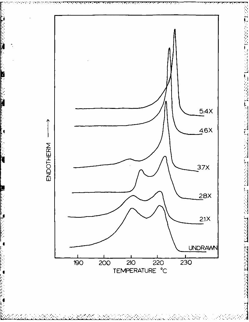
thoroughly dried gel (Figure 1) shows two prominent endotherms with peak melting
point at 210 and 219.5C. The two endotherms have approximately equal peak
area. Double endotherms in solution crystallized Nylon 6 have previously been
reported18,19 . Kyotani 19 attributed the low temperature cndotherm to lamellar
crystals which crystallized during cooling the solution to room temperature
after isothermal crystallization. Prolonging the isothermal crystallization
time was reported to give only a single high temperature endotherm of more per-
fect, larger lamellar crystals. However, Stamhuis and Pennings13 had shown that
Nylon 6 gel morphology exhibits long ribbons of aggregated fibrillar crystals.
This fibrillar morphology was also obtained from stirred crystallization in
1,2,6-hexanetriol solution giving a melting point of 223 - 2240C1 9 . Thus in the
present gel system, the observed high temperature endotherm is likely for
fibrillar crystals mixed with possibly some large lamellar crystals.
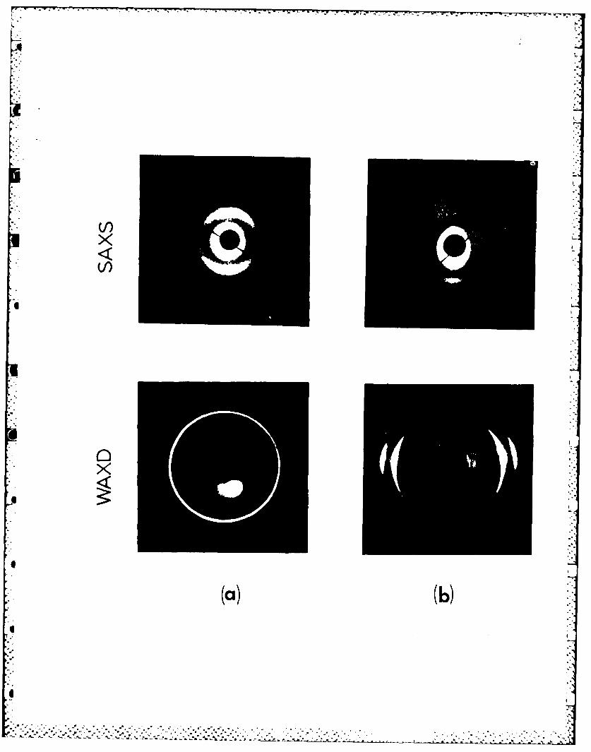
Figure 2 shows WAXD and SAXS photographs of a dried gel film prior to
extrusion draw. The x-ray beam was directed perpendicular and parallel to the
film plane. Viewed perpendicularly, Figure 2(a), there are two (200) and (002)
isotropic rings. The inner (200) refle'tion is much more intense than the outer
(002) reflection. SAXS however shows that over a larger range, the system is
not entirely isotropic as indicated by an uneven intensity for the ring. When
71
-8-
the x-ray beam is placed parallel to the film plane, Figure 2(b), wide
equatorial (200) and (002) arcs are superimposed on the Debye rings, and SAXS
shows wide meridional maxima. These indicate that orientation has been intro-
duced in the gel film with the b-chain axis weakly oriented perpendicular to the
film plane as a result of squeezing during solvent removal. This is *onfirmed
by WAXD photograph, taken with the beam parallel to an unpressed gel, which
shows only isotropic rings. The preorientation, however, does not cause double
orientation of crystals in the drawn gel, to be discussed later. It does affect
the distribution of crystals when viewed parallel to the draw direction.
Properties of Drawn Gel Film
Thermal evaluation by DSC of the drawn gel film is shown in Figure 1. With
increasing draw ratio, the low temperature endotherm decreases in magnitude and
shifts slightly towards higher temperature, completely disappearing at a draw
4.6X and onwards, leaving only a single endotherm with a peak melting at 224 0C
at draw 5.4X. The disappearance of the low temperature endotherm must be due to
the destruction of these lamellar crystals on draw leading to their incor-
poration in a newly-formed fibrous morphology. The fate of the ribbons of
fibrillar crystals on draw is not revealed by DSC since its melting point is in
the same range as that of the drawn fibrous morphology 20 . The fraction of
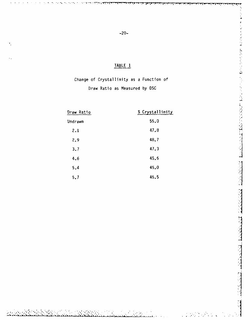
crystallinity decreases with draw by -9% at the highest draw ratio 5.7 (Table
1). A major decrease has also been reported for crystalline poly(ethylene
terephthalate) 21 with yet no satisfactory explanation.
I
-9-
As pointed out earlier, Nylon 6 gel formation does not necessarily result
in significant reduced molecular entanglement. The maximum draw ratio of 5.7
obtained here is comparable to those previously reported for Nylon 6. Tensile
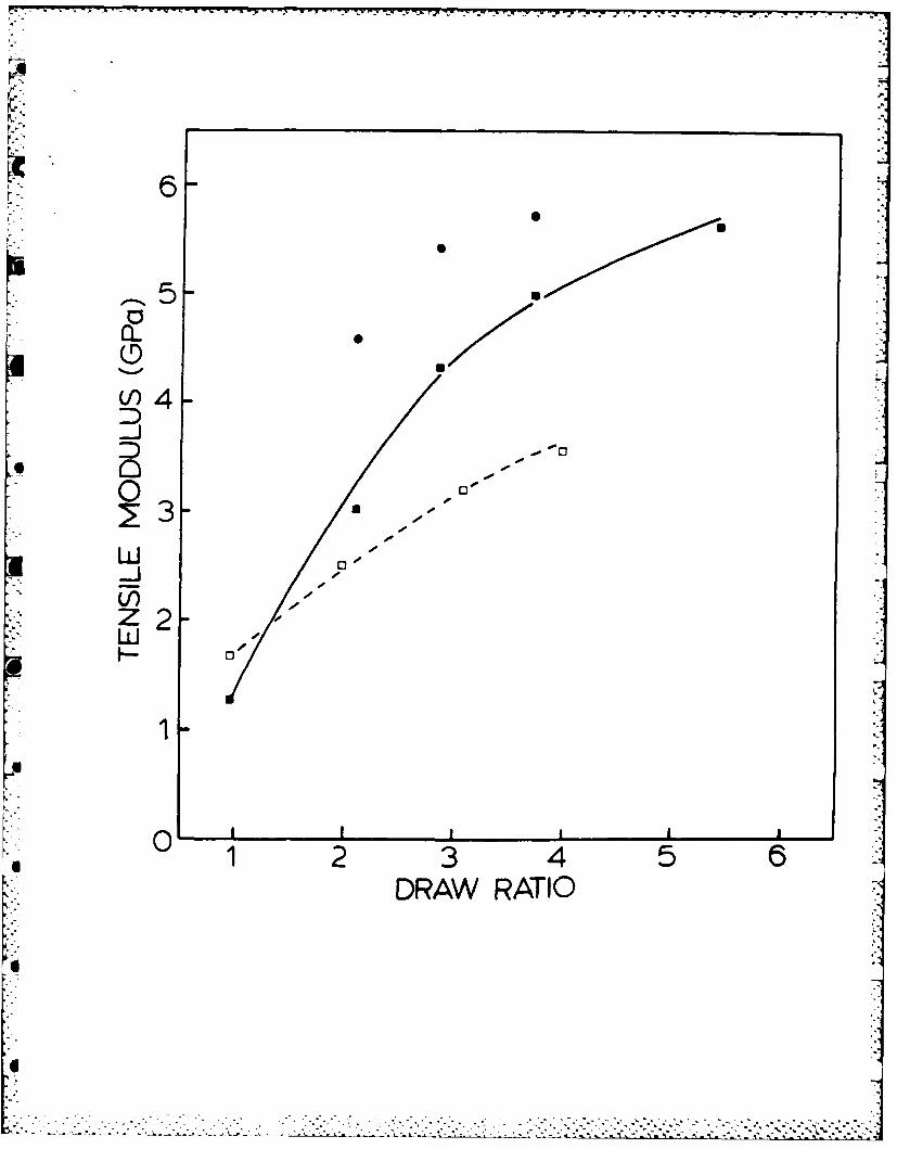
moduli of the drawn gel are shown in Figure 3. The moduli of solvent cast film,
drawn under similar conditions, shown by the broken line, are included for com-
parison. At equivalent draw ratios, the modulus of gel film is modestly higher,
reaching 5.6 GPa. Annealing at 1900C under tension shows a slight improvement
in the modulus, from 5.0 GPa to 5.7 GPa for draw ratio 3.7.
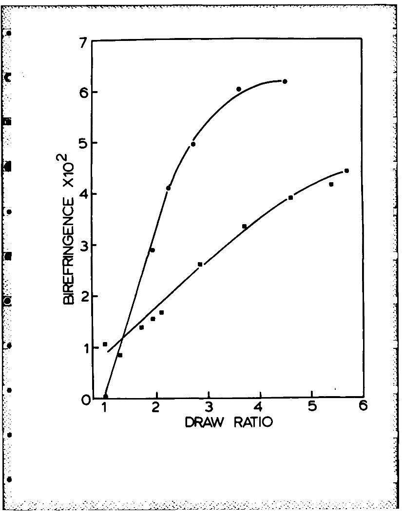
The total orientation of both the amorphous and crystalline chains was
measured by birefringence (Figure 4). The undrawn film shows birefringence of
0.011, which is due to orientation introduced during solvent removal. On
drawing, the birefringence increases, almost linearly to 0.044 at a draw of 5.7.
However, the drawn cast film shows a marked increase in birefringence at low
draw, reaching a plateau of 0.061 at a draw of 3.5 with values consistent with
reports on uniaxially drawn Nylon 6 film and filament 22 . The lower
birefringence of the drawn gel is consistent with investigations by both WAXD
and SAXS which show double orientation; there are two populations of crystals
with chain axis either parallel or perpendicular to the draw direction. Since
birefringence is the difference in refractive indices along and perpendicular to
draw, the presence of crystals with chain axis perpendicular with draw direction
reduces the birefringence.
Deformation Mechanism
Double orientation on deformation has been reported for several types of
gel 2 3,24,25 . An elegant explanation has been offered by Keller12 in which the
initial gel contains a mixture of both micellar and lamellar crystals. On
deformation, the micellar crystals orient with their chain axis in the draw
direction as in the stretching of a network. Conversely, the lamellar crystals
align with their lamellar planes along the stretch direction and therefore with
chain axis perpendicular to draw. An unconnected lamellar crystal could
possibly orient this way on drawing without much chain unravelling. It is less
likely that lamellar crystals, presumably with interconnections, will do so
rather than orienting with chain unravelling to form fibrous morphology in the
draw direction.
Since gelation of Nylon 6 is caused by the interlacement of fibrillar
crystals, we propose an alternative mechanism for draw of Nylon 6 gel.
Orientation of crystals with chain axes in the draw direction arises from the
fibrous morphology normally observed in uniaxial drawing. The second orien-
tation of crystals, with chain axis perpendicular to draw direction, are from
the fibrillar crystals which have chain axis perpendicular to surface plane and
hydrogen bonding in the long axis. They rotate when subjected to torque on
deformation so that the long axis (a-axis) is preferentially oriented in the
draw direction. This is similar to the rotation of needle shape crystals in
segmented polyurethane to give a negative orientation as proposed by Bonart 26.
We have shown that this proposed mechanism is consistent with both the WAXD and
SAXS study as a function of draw ratio for the gel.
Figure 5 shows a series of WAXD photographs of gel film with increasing
draw ratio- the x-ray beam is normal to film plane. The undrawn film shows
-24-
FIGURE CAPTIONS
FIGURE 1: Thermal Behavior by DSC of Undrawn and Drawn Nylon 6 Gel Film
FIGURE 2: WAXD and SAXS Photographs of Undrawn, Dried Gel with Beam,
(a) Normal and (b) Parallel to Film Plane
FIGURE 3: Tensile Modulus as a Function of Draw Ratio
C Solvent-Cast Nylon 6 Film,
I Nylon 6 Gel Film,
* Gel Film After Annealing
FIGURE 4: Birefringence as a Function of Draw Ratio
Nylon 6 Gel Film,
* Solvent-Cast Nylon 6 Film
FIGURE 5: WAXD Photographs of Gel Film with Increasing Draw Ratio.
X-ray Beam Normal to Film Plane
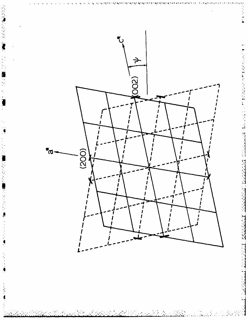
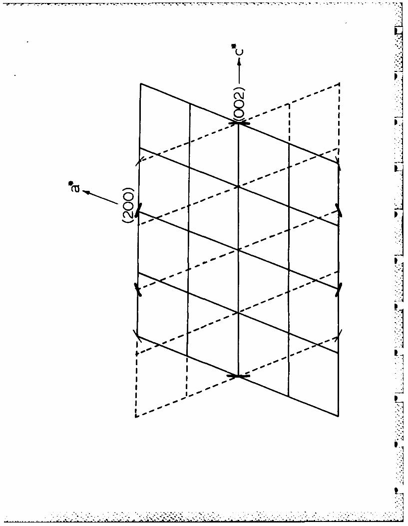
FIGURE 6(a) & (b):Reciprocal Lattice Representation of Nylon 6 a-Crystal Show-
ing Relative Position of (200), (002) and (202) Reflections
in WAXD. (a) Low draw, <1.9x, (b) high draw, >3.7x.
FIGURE 7: SAXS Photographs of Gel Film with Increasing Draw Ratio.
X-ray Beam Normal to Film Plane
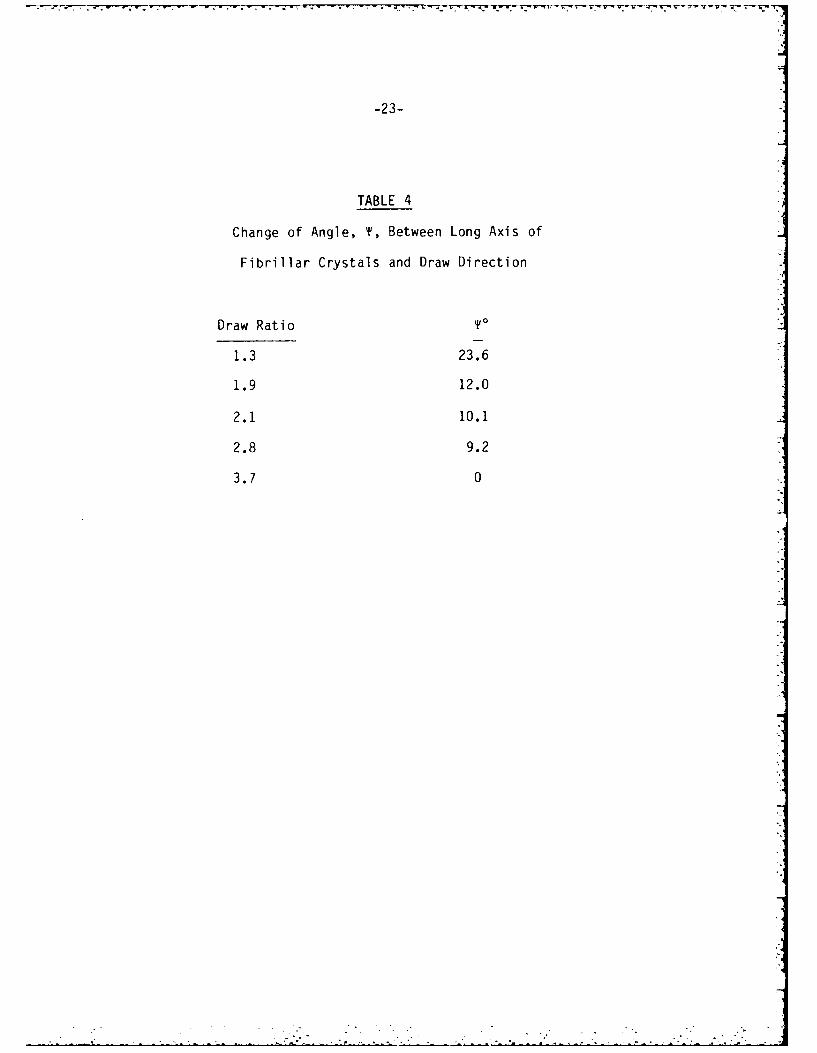
-23-
TABLE 4
Change of Angle, T, Between Long Axis of
Fibrillar Crystals and Draw Direction
Draw Ratio To
1.3 23.6
1.9 12.0
2.1 10.1
2.8 9.2
3.7 0
. . . .
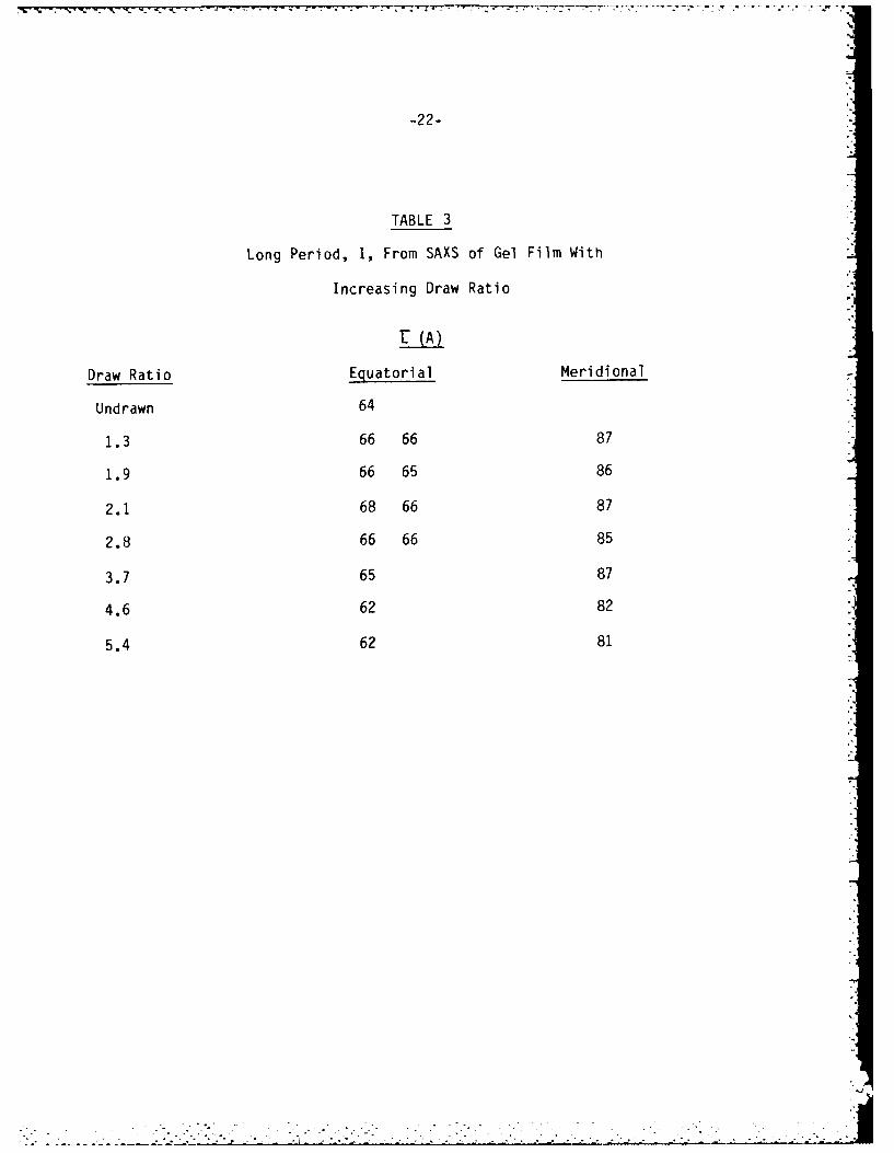
-22-
TABLE 3
Long Period, 1, From SAXS of Gel Film With
Increasing Draw Ratio
U (A)
Draw Ratio Equatorial Meridional
Undrawn 64
1.3 66 66 87
1.9 66 65 86
2.1 68 66 87
2.8 66 66 85
3.7 65 87
4.6 62 82
5.4 62 81
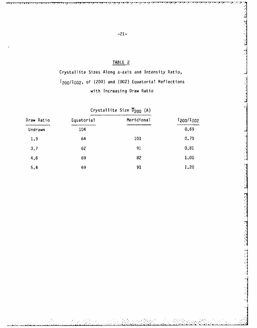
-21- 1TABLE 2 I
Crystallite Sizes Along a-axis and Intensity Ratio,
1200/1002, of (200) and (002) Equatorial Reflections
with Increasing Draw Ratio
Crystallite Size 'U200 (A)
Draw Ratio Equatorial Meridional 1200/1002
Undrawn 104 0.69
1.9 64 101 0.70
3.7 62 91 0.81
4.6 69 82 1.00
5.4 69 91 1.20
-20-
TABLE 1
Change of Crystallinity as a Function of
Draw Ratio as Measured by DSC
Draw Ratio %Crystallinity
Undrawn 55.0
2.1 47.*82
2.9 48.7
3.7 47.34.6 45.*6
5.4 45.0
5.7 45.5
-19-
15. A.E. Zachariades, P.D. Griswold and R.S. Porter, Polym. Eng. Sci., 19, 441
(1979).
16. R.S. Stein, J. Polym. Sci., 24, 383 (1957).
17. C.R. Desper, Ph.D. Thesis, University of Massachusetts, 1966.
18. T. Shimada and R.S. Porter, Polymer, 22, 1124 (1981).
19. M. Kyotani, J. Macromol. Sci., Phys., B21, 275 (1982).L
20. M. Todoki and T. Kawaguchi, J. Polym. Sci., Phys. Ed., 15, 1507 (1977).
21. J.R.C. Pereira and R.S. Porter, J. Polym. Sci., Phys. Ed., 21, 1147 (1983).
22. F. Fujimoto et.al., Nippon Sen'i Kikai Gakkai, 19, 1 (1973).
23. H. Berghman, F. Govaerts and N. Overbergh, J. Polym. Sci., Phys. Ed., 17,
1251 (1979).24. S.J. Guerrero, A. Keller, P.L. Soni and P.H. Geil, J. Polym. Sci., Phys•
Ed., 18, 1533 (1980).
25. E.D.T. Atkins et.al., Colloid Polym. Sci., 262, 22 (1984).
26. R. Bonart and K. Hoffmann, Colloid & Polym. Sci., 260, 268 (1982).
27. B. Wunderlich, "Macromolecular Physics, Vol. I", Academic Press, 1973. ]I
I.: -,- :,• ,5 := x a - -:- - , I_, Z : ' L- , : : i - "-!- : .:?.':.:.:; i. _ ..:, '?,.-- L .. -* .-- I."
. ...
-18-
REFERENCES
1. A.J. Pennings and K.E. Meihuizen, in "Ultra-High Modulus Polymers",
A. Ciferri and I.M. Ward, Editors, Applied Science, 1979.
2. P.J. Barham, Polymer, 23, 1112 (1982).
3. M.R. Mackley and G.S. Sapsford, in "Developments in Oriented Polymers-I",
I.M. Ward, Editor, Editor, Applied Science, 1982.
4. P. Smith and P.J. Lemstra, J. Polym. Sci., Polym. Phys. Ed., 19, 1007
(1981).
5. M. Matsuo and R. St. John Manley, Macromolecules, 15, 985 (1982).
6. C.G. Cannon, Polymer, 23, 1123 (1982).
7. A. Peguy and R. St. .ohn Manley, Polymer Commun., 25, 39 (1984).
8. D.T. Grubbs, 4th Cleveland Macromolecule Symposium, June, 1983.
9. D.J. Lloyd, in "Colloid Chemistry, Vol. I", J. Alexander, Editor, New York,
1926 (quoted in Ref. 11).
10. A. Tager, "Physical Chemistry of Polymers", MIR Publications, 1978.
11. P.H. Hermans, in "Colloid Science, Vol. II", H.R. Kuryt, Editor, Elsevier,
1949.
12. A. Keller, in "Structure-Property Relationships of Polymeric Solids",
A. Hiltner, Editor, Plenum Press, 1983.
13. J.E. Stamhuis and A.J. Pennings, British Polym. J., 10, 221 (1978).
14. H.H. Chuah and R.S. Porter, J. Polym. Sci., Phys. Ed., 22, 1353 (1984);
A.E. Zachariades, M.P.C. Watts, T. Kanamoto and R.S. Porter, J. Polym.
Sci., Polym. Lett. Ed., 17, 485 (1979).
-17-
annealing, because of reorientation, the annealed samples not only have higher
birefringence but also increase with tilt angle. The increase is linear for
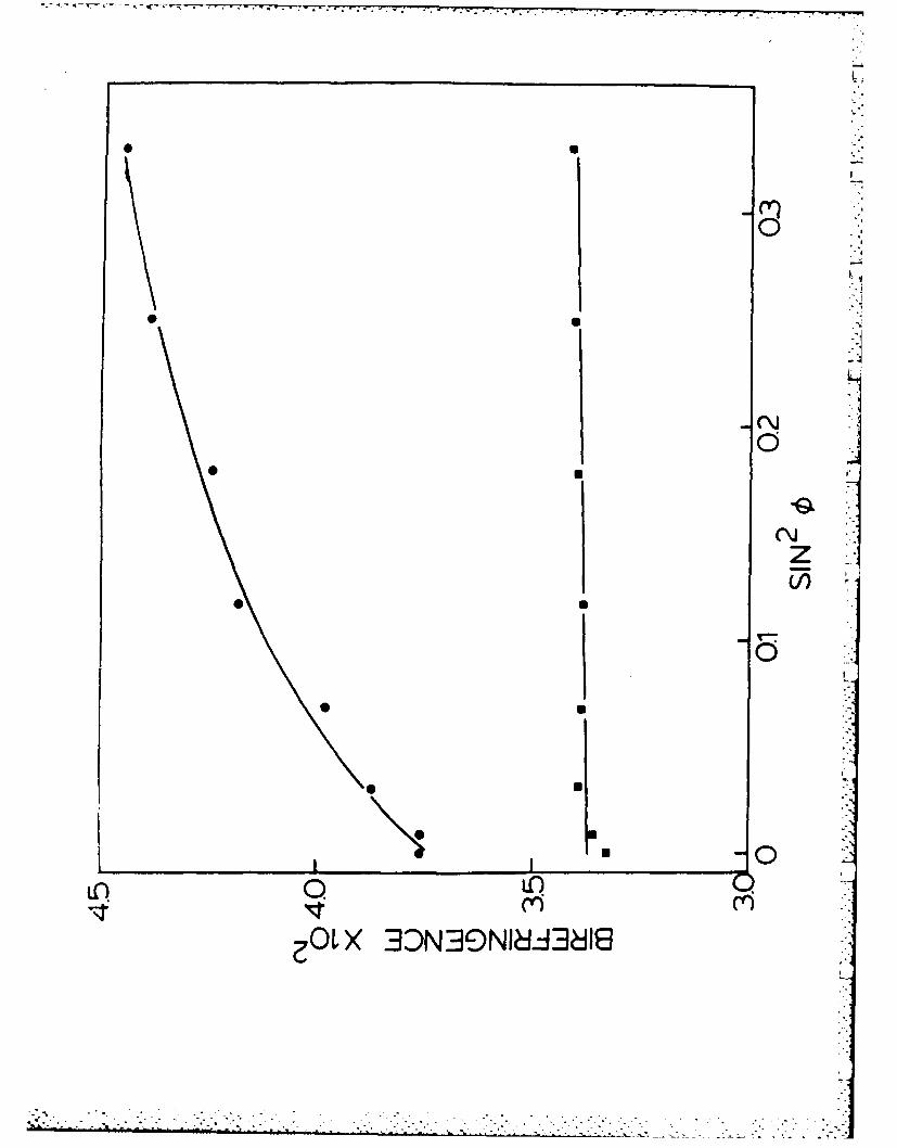
draw 2.9X up to the angles measured but show tendency of reaching plateau in
draw 3.7X. For a biaxial orientation, birefringence at = 0' is different from
at * = 90'. Plot of birefringence vs. sin 2 is linear and extrapolation to
sin 2 @ = 1 gives birefringence of the other axes pair 17 . Although annealed 2.1X
film shows a linear increase, it is uncertain that this can be extrapolated to
imply biaxial orientation, especially the annealed 3.7X film shows non-linear
increase. Therefore, reorientation on annealing produced a much more compli-
cated overall orientation.
CONCLUSIONS
Partially dried Nylon 6 gel film was drawn by co-extrusion with
poly(oxymethylene) as outer billet at 150 0C in an Instron rheometer up to a
maximum draw ratio of 5.7X. Tensile moduli are comparable to those obtained in
a drawn solvent-cast Nylon 6. The drawn gel film showed a double orientation
with one population of crystals oriented with chain axis in the draw direction.
These crystals originated from the drawn fibrous morphology. The other crystal
population had chain axis perpendicular to draw direction and identified as the
fibrillar crystals that cause gelation. A deformation mechanism leading to this L
double orientation, is proposed from the study of birefringence, WAXD and SAXS.
Annealing at 190'C causes reorientation of the fibrillar crystals resulting in a
more complex orientation.
ACKNOWLEDGEMENT
We wish to express appreciation to the Office of Naval Research for the
support of this research.
4•
-16-
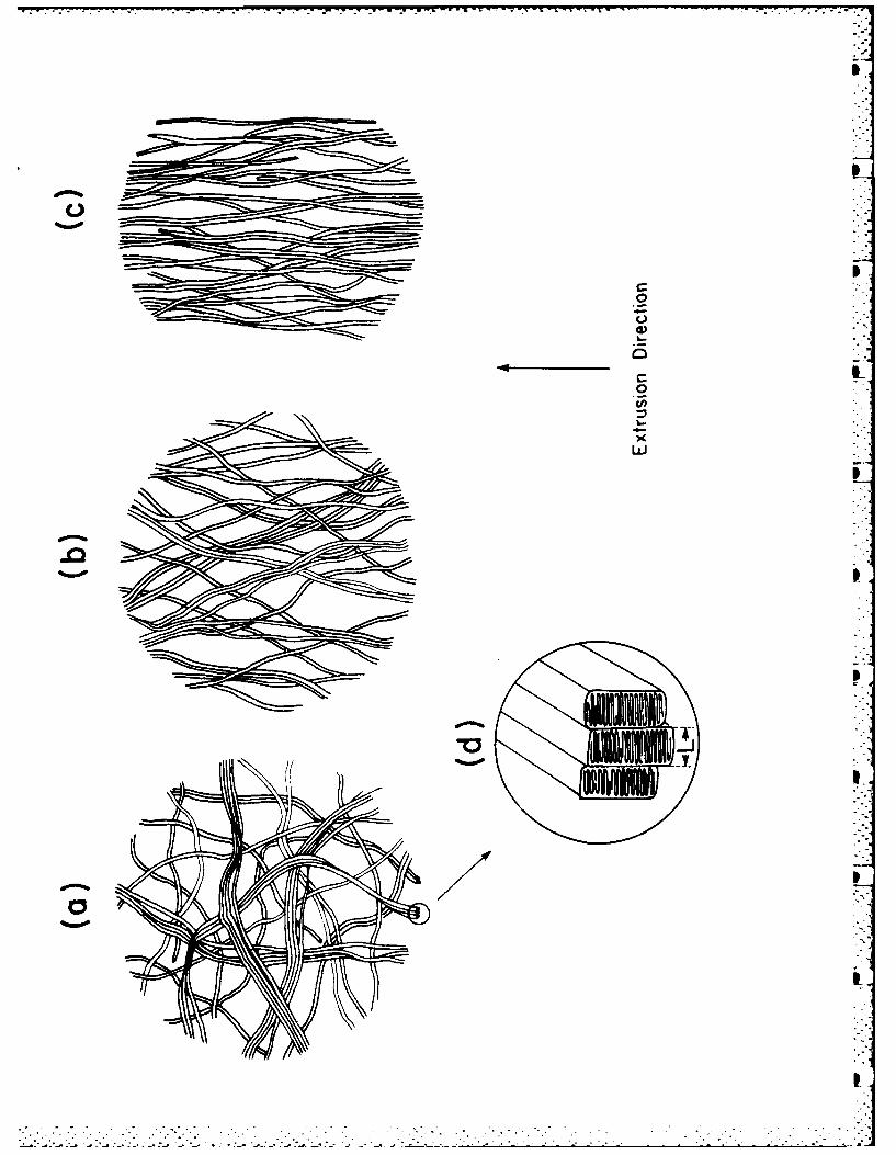
not the molecular chain. At low draw, Figure 8(b) shows the long axes partially
oriented towards the draw direction. Since the fibrillar crystals are distri-
buted about the draw direction, this arrangement gives four-point SAXS pattern
at the equator. On further drawing, Figure 8(c), the long axes are in the draw
direction; the four-point scattering merges into two equatorial scatterings.
Superimposed on this, the simultaneous development of fibrous morphology gives
the meridional scatterings, therefore, a resultant four-point scattering of
Figure 7.
Annealing Behavior
The drawn gel films were annealed under tension at 190°C for 3 hours. The
modulus and birefringence increase slightly (Figures 3 and 4). WAXD and SAXS
with x-ray beam in normal and transverse directions are not significantly dif-
ferent from that of unannealed samples. However, when the beam is in the draw
direction, superimposed on both (200) and (002) rings are intense arcs at the
equator similar to that of undrawn state of Figure 2. Reorientation of the
fibrillar crystals occurs on annealing with chain axis partially reoriented nor-
mal to film plane. Crystals that randomize around the draw direction must be in
a metastable state. Annealing reverses the process, resulting in a more compli-
cated orientation.
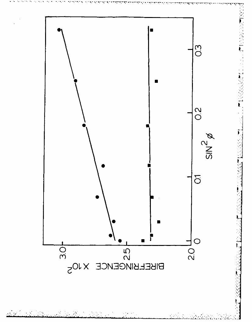
Birefringence of both unannealed and annealed gel film of draw 2.1X and
3.7X are shown in Figures 9(a) and (b) as a function of tilt angle, €. For
unannealed samples, there is only a slight increase in birefringence with .
indicating a slight departure from isotropy around the uniaxial draw axis. On
-15-
equatorial periodicity of the fibrillar crystals is smaller however but remains
fairly constant at -65 A on draw. Although Stamhuis and Pennings 13 reported the
lateral dimension of such crystals to be 100-200 A, thickness in the chain
direction was not reported. The present periodicity is within the range for
lamellar thickness reported for solution grown Nylon 6 crystals 27.
The split angle, I, of the equatorial scattering maxima gives the average
angle of the long axis of fibrillar crystals to the draw direction. At a draw
of 1.3X, the angle is 23.60 and decreases to 00 at 3.7X (Table 4). At 0'
angle, the long axis (a-axis) of the fibrillar crystals is completely oriented
in the draw direction. The SAXS results support the observation from WAXD.
From both WAXD and SAXS study, we showed double orientation in the drawn
gel film. One population of crystals has chain axis parallel to the uniaxial
draw direction. This type of crystals belong to the fibrous morphology normally
found in tensile drawing. The other crystal population has a chain axis perpen-
dicular to draw, and they are identified as the fibrillar crystals associated
with gelation. They rotate when subjected to torques during deformation, with
the long axis orienting towards the draw direction. Because hydrogen bond is
also in the long axis, chains resist drawing until later stages when "fracture"
possibly occurs and transform partly into fibrous morphology. This causes the
depletion of the fibrillar crystals and therefore decrease in intensity in both
their WAXD and SAXS. Figure 8 is a schematic of ribbons of these fibrillar
crystals undergoing deformation with long axis rotating towards the draw direc-
tion. The lines represent fibrillar crystals, bundle into large ribbon, and
: i~ ~ i~i .. . * -. . * *...........i~i : i ./ . .* ii i I
-14-
(202) reflections. The crystallite sizes of fibrillar crystals along a-axis, as
measured from broadening of meridional (200) reflection, showed a slight
". decrease on draw, from 101 A at 1.9X to 82-91 A at higher draw. For equatorial
(200) reflection, the crystallite sizes remain fairly constant on draw, 62-69 A.
This dimension may be interpreted as the lateral size of the drawn microfibril.
Consider the interchain dimension of 4-5 A, arithmetically, this corresponds to
about 15 Nylon 6 chains in close lateral packing. This number indicates that
the equatorial (200) reflection is unlikely the result of drawn micellar
crystals network.
While the WAXD study gives us information of how chains are oriented at the
level of unit cell axes, SAXS provides a view on orientation at the larger
lamellar level. Figure 7 shows SAXS patterns of gel film with increasing draw
ratio. At a low draw of 1.3X, there is a marked change of the scattering pat-
tern from nearly isotropic scattering for the undrawn state to a discrete four-
point pattern along the equator. At higher draw, the four-point moves closer,
while meridional scattering develops at 1.9X, thus giving a six-point scattering
pattern. On further draw, the equatorial four-point merges into two-points at
3.7X, giving a final four-point scattering along the meridian and equator.
To show that the equatorial scattering is not due to voids, the drawn film
was immersed in benzyl alcohol (refractive index 1.54) for 14 days. It was then
coated with paraffin oil to reduce solvent evaporation under vacuum while taking
SAXS patterns. The patterns found are the same, indicating the equatorial scat-
tering is not due to voids.
The measured lamellae long periods are tabulated in Table 3. The meri-
dional long period of the drawn fibrous morphology is constant at -85 A. The
A* - . -. ** .
A-13-
by a reciprocal lattice as in Figure 6(b). In this case the meridional (200)
reflections show intensity maxima at an angle of 22.50 from the draw direction,
which is indeed observed from draw ratio 3.7X onwards indicating a complete a-
axis orientation of the fibrillar crystals in draw direction. A weak (202)
reflection appears diagonally in the reciprocal lattice and is also observed in
the diffraction pattern.
If we now superimpose in Figure 6(b) the equatorial (200) and (002) reflec-
tions from the normal fibrous morphology with chain axis in draw direction, the
composite pattern is consistent with observations for a draw 3.7X of Figure 5.
Only the (002) reflection appears from crystals with both orientations, and
therefore its intensity must be enhanced. For isotropic a-crystals, the inten-
sities of (200) and (002) reflections are nearly equal. Table 2 shows that the
ratio of intensities, 1200/1002, for (200) and (002) equatorial reflections is
0.69 and increases to 1.20 at a draw 5.4X. The increase in this intensity ratio
is a result of randomization of fibrillar crystals around the draw axis and at
high draw ratio, the eventual fracture of these crystals to orient in the draw
direction.
Crystallite sizes along a-axis for both types of crystal orientations, are
measured from WAXD (200) line broadening, and are shown in Table 2. Scherrer's
equation was used after correction for instrumental broadening. It is assumed
that broadening is due to crystallite size alone, neglecting lattice distortion.
Therefore, the measured sizes are a lower limit. Measurement of (002)
broadening is not suitable, as it is not a pure peak containing a mixture of
6
6%
-12-
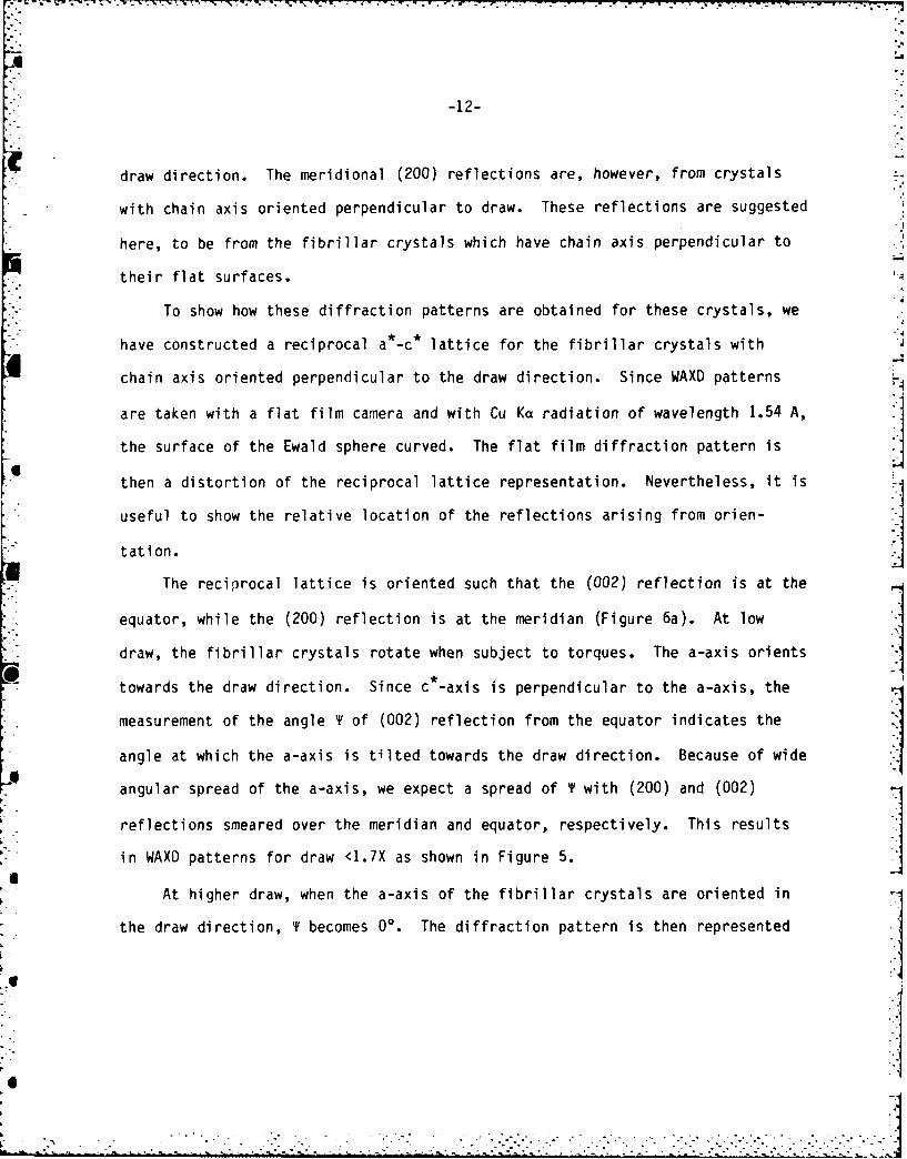
draw direction. The meridional (200) reflections are, however, from crystals
with chain axis oriented perpendicular to draw. These reflections are suggested
here, to be from the fibrillar crystals which have chain axis perpendicular to
their flat surfaces.
To show how these diffraction patterns are obtained for these crystals, we
have constructed a reciprocal a*-c* lattice for the fibrillar crystals with
chain axis oriented perpendicular to the draw direction. Since WAXD patterns
are taken with a flat film camera and with Cu Ka radiation of wavelength 1.54 A,
the surface of the Ewald sphere curved. The flat film diffraction pattern is
then a distortion of the reciprocal lattice representation. Nevertheless, it is
useful to show the relative location of the reflections arising from orien-
tation.
The reciprocal lattice is oriented such that the (002) reflection is at the
equator, while the (200) reflection is at the meridian (Figure 6a). At low
draw, the fibrillar crystals rotate when subject to torques. The a-axis orients
towards the draw direction. Since c -axis is perpendicular to the a-axis, the
measurement of the angle T of (002) reflection from the equator indicates the
angle at which the a-axis is tilted towards the draw direction. Because of wide
angular spread of the a-axis, we expect a spread of T with (200) and (002)
reflections smeared over the meridian and equator, respectively. This results
in WAXD patterns for draw <1.7X as shown in Figure 5.
At higher draw, when the a-axis of the fibrillar crystals are oriented in
the draw direction, T becomes 00. The diffraction pattern is then represented
V I, -.- ' *- * * . . .. . . . .
-11-
isotropy with (200) and (002) Debye rings. The outer (002) reflection is mixed
with (202), for convenience, we refer to this as (002) only. At low draw ratio,
up to 1.7, the inner (200) reflection forms meridional arcs with broad azimuthal
spread, while the outer equatorial (002) arcs are also broad but less intense.
At a draw ratio of 1.9, the spread of these two arcs becomes narrower with
simultaneous development of a faint (200) reflection at the equator. These
I equatorial arcs become prominent at a draw 2.9X while the meridional (200) arcs
become narrower in spread and split with maximum intensity centered at -220
angle to the extrusion direction. Correspondingly, the azimuthal spread of
* (002) also becomes narrower. There is a faint reflection located diagonally
with spacing nearly the same as that of the outer (002) reflection, which we
identify as a weak (202) reflection. At higher draw of 4.6, the intensity of
meridional (200) arcs decreases sharply when compared to its equatorial reflec-
tion.
Because of the complex orientation, we also examined both WAXD and SAXS
0with the x-ray beam transverse and parallel to the draw direction. The trans-
verse diffraction shows similar patterns as that of normal beam. At low draw,
the parallel direction diffraction shows a weak orientation introduced during
squeezing in gel film preparation with broad equatorial (200) arcs. On further
drawing to 3.7X, it develops into a ring of uneven intensity showing tendency of
randomization around the draw direction; so the system can be described as
having double orientation of the crystals but to some extent, isotropic around
the draw direction at higher draw.
In Figure 5, the equatorial (200) and (002) reflections can be identified
as from the normal fibrous morphology with chain axes parallel to the uniaxial
U
-25-
FIGURE 8: Schematic Representation of Orientation of Fibrillar Crystals
During Deformation
(a) Undrawn State with Random Interlacement of Fibrillar
Crystals
(b) Low Draw Ratio ( 1.9X, Long Axis (a-axis) of Fibrillar
Crystals Orienting Towards Draw Direction
(c) High Draw Ratio, long axis of Fibrillar Crystals in
Draw Cirection
(d) Enlargement of Aggregate of Fibrillar Crystals Showing
the Long Period
FIGURE 9: Birefringence as a Function of Tilt Angle d for Unannealed
(m), and Annealed (e) Drawn Gel
(a) Draw Ratio 2.9
(b) Draw Ratio 3.7
.
7T WTir
037Q
190 200 210 220 230K TEMPERATURE 0C
Z . -. - -. . - . .- - *..m . . . . . .
- - - . - . - - - q - - - - - -- - -
4L
I.
0
(A
II
I
I
(a) (b)I
4
K 6 -
5U
UOU
-J
0-2 3-
DRA RAI
4 -. . .~ ~ ~ - - - - -. - - . ..
7
CM~
w 4 -
z
2 3m
DRAW RATIO
xx
0
* NOII38IO NOISfldiX3
A -
I,U
4 -
I
II
1 IIII
jI I
J
I U ~1II
II
L - - - - -
I
N.
I
opp
sop.
100 aL
do 1O
doI
0 wo wI
0 'oo do
C~IooI
oo NOdOP1
. . .
. . . . . . . . . . . . . .. .. . . . .. *. ***
I. -i-z
Ix -~ N- 0i)HC os~X
IL0
4-J
%moo*
-0
0 Ln 0*Y U j
OLX 3339NlA~dl
~-- ' .---*-----~---.r--~--.-.~..............................-
V
U
I-
~1o
0 U
0 U
(\J
z0 U
50 U
0 U
0
Q iC)
Cr)
>( BDNBSNIddBdI8
- -- .-- to-, . 'P r 9 rrr'r -w
FILMED
8-85
DTIC