Embed Size (px)
Citation preview
MASSIVit Service Group SP-07-001 Rev 12
G
This document contains proprietary and confidential material of MASSIVit Ltd. Any unauthorized reproduction,
use, or disclosure of this material, or any part thereof, is strictly prohibited. This document is solely for the
use of MASSIVit employees and authorized MASSIVit customers.
MASSIVit 3D Printers 1800 Series Site Preparation Guide

1 Need help? Contact [email protected] Site Preparation Manual
The material furnished in this document is believed to be accurate and reliable. However, no
responsibility is assumed by MASSIVit 3D for the use of this document or any material included
herein.
MASSIVit 3D reserves the right to make changes to this document or any material included
herein at any time and without notice.
© Copyright MASSIVit 3D 2017 – Confidential
Contact MASSIVit 3D at:
MASSIVit 3D Headquarters 11 Pesah Lev st. Lod 712936 Israel Phone: (972) 8-6519486 Fax: (972) 8-6900758 Email: [email protected]
European Office 11 Pesah Lev st. Lod 712936 Israel Phone: (972) 8-6519486 Fax: (972) 8-6900758 Email: [email protected]
North-American Office 11 Pesah Lev st. Lod 712936 Israel Phone: (972) 8-6519486 Fax: (972) 8-6900758 Email: [email protected]
Chinese Office 11 Pesah Lev st. Lod 712936 Israel Phone: (972) 8-6519486 Fax: (972) 8-6900758 Email: [email protected]
Website: http://massivit3d.com
Customer Support: [email protected]

2 Need help? Contact [email protected] Site Preparation Manual
Table of Contents Introduction ............................................................................................................................................... 4
About the MASSIVit 3D Printers site preparation .............................................................................. 4
Safety .......................................................................................................................................................... 5
General Precautions and Cautions ................................................................................................... 5
Fire Prevention ........................................................................................................................................ 5
Waste Disposal ...................................................................................................................................... 5
Materials Handling ................................................................................................................................. 6
Personnel Safety Considerations ........................................................................................................ 6
Accountability .......................................................................................................................................... 7
Shipping and Handling ......................................................................................................................... 7
Site and Facilities Requirements ......................................................................................................... 7
Lifting and Delivery ................................................................................................................................ 7
Unpacking and Installation .................................................................................................................. 7
System Overview...................................................................................................................................... 8
Printer Dimensions and Weight .......................................................................................................... 8
Machine Height Configurations ....................................................................................................... 9
System External Components ........................................................................................................... 10
Site Requirements .................................................................................................................................. 11
Unloading Space ................................................................................................................................. 11
Doors and Hallways Clearances ...................................................................................................... 11
Conveying equipment ....................................................................................................................... 11
Workspace Clearances ..................................................................................................................... 12
Floor Surface and Strength ................................................................................................................ 13
Temperature and Humidity ................................................................................................................ 14
Ventilation and Fume Extraction ...................................................................................................... 14
Facility Requirements ............................................................................................................................ 15
Electrical Infrastructure ...................................................................................................................... 15
Pneumatic Requirements ................................................................................................................... 18
Lighting................................................................................................................................................... 19
Communication ................................................................................................................................... 19
Graphic PC requirements .................................................................................................................. 19
Gel storage ........................................................................................................................................... 20
Fire Extinguisher .................................................................................................................................... 20
Eyewash Station ................................................................................................................................... 20
Appendix A: Site Preparation Check List .......................................................................................... 21

3 Need help? Contact [email protected] Site Preparation Manual
Table of Figures Figure 1: Printer Dimensions drawing ......................................................................................................... 8
Figure 2-Layout drawing .............................................................................................................................. 9
Figure 3- Machine layout ........................................................................................................................... 10
Figure 4: Interface Box ................................................................................................................................ 10
Figure 5: Workspace Clearances ............................................................................................................. 12
Figure 6-Leveling and Supporting Pads - Specifications...................................................................... 13
Figure 7-European connection diagram ................................................................................................ 16
Figure 8-North America connection diagram ....................................................................................... 17
Table List Table 1-Dimensions and Weight ................................................................................................................. 9
Table 2-Electrical Requirements ............................................................................................................... 15
Table 3-Power Consumption ..................................................................................................................... 15
Table 4-Transformer specifications ........................................................................................................... 16
Introduction
4 Need help? Contact [email protected] Site Preparation Manual
Introduction
About the MASSIVit 3D Printers site preparation
This document is intended to guide and assist you in preparing your site for the MASSIVit
3D 1800 Series printers and includes prerequisites regarding the various elements
needed on site prior to installation.
The tables and figures herein provide the different dimensions and weights of the
assembled systems as well as various helpful information intended to assist you in
planning the placement site.
Read and thoroughly understand the information in this manual safety instructions. If
any part of this manual is not clear, contact MASSIVit 3D Customer Support for
clarifications.
MASSIVIT representatives supervise the unloading, unpacking, transfer and placement
of the printer at its destination and final installation process.

Safety
5 Need help? Contact [email protected] Site Preparation Manual
Safety
General Precautions and Cautions
This product is designed and manufactured to ensure maximum safety of operation. It
should be operated and maintained in strict compliance with the safety precautions,
warnings, and operating instructions contained in official MASSIVit 3D publications.
Do not modify the printer in whole or in part in any way without prior written
approval by MASSIVit 3D.
Do not connect any third-party equipment to the printer without written approval
from MASSIVit 3D.
Make sure that only properly trained and fully qualified personnel are authorized
to operate this equipment.
Unauthorized personnel should not be allowed access and provide with any form
of service to the printer.
In the event of system malfunction or of improper response to safety controls,
suspend all operation of the equipment, and notify MASSIVit 3D’s Customer
Support Department immediately.
Fire Prevention Do not use water to put out a fire. Use water spray only to cool containers. Do not
pour water on leaked materials.
Additional Fire Prevention equipment should be installed according to local laws
and regulations.
Waste Disposal
Liquid and solid waste should be disposed of per local laws and regulations, including:
Printing material containers
Wipes and gloves used for cleaning the printer

Safety
6 Need help? Contact [email protected] Site Preparation Manual
Materials Handling
DIMENGEL 100 BASE containers should be kept tightly closed in a dry and well-ventilated
place, keep away from heat and out of direct sunlight.
Maximum storage temperature: 30°C (86°F)
Containers can be stacked up to a maximum of 3 containers on top of one
another.
Personnel Safety Considerations
Facility personnel (especially operators) should be familiar with the emergency power
shutdown procedure and with how to notify the local fire department. Being sufficiently
prepared for an emergency can help prevent injury and save expensive equipment.
Electrical Shock Hazard
The customer responsibility is to ensure that electrical works comply with the local
electrical code and the relevant laws and regulations. The customer should provide
qualified and registered electricians to perform operations as required by these laws
and regulations.
Massivit Dealers and service personnel are not authorized to perform maintenance
processes for the site electrical infrastructure and printer’s connections to this structure.
Safe isolation of the printer from power prior to service operations shall be done
according to the local regulation, and is under the customer responsibility.
Hand Protection
Always use powder free protective gloves when handling the Gel system, cleaning
fluids or waste liquids. The Gel contains irritant materials. Prolonged or repeated
contact with hands may result in symptoms such as redness and irritation. These
symptoms may not appear immediately.
Eye Protection
Always use protective goggles when handling the Gel. The Gel contains irritant
materials. Contact with eyes may result in symptoms such as redness and irritation.
These symptoms may not appear immediately.

Accountability
7 Need help? Contact [email protected] Site Preparation Manual
Accountability
Shipping and Handling
MASSIVit 3D will deliver the machine packed and ready for shipment (sea or air) at the
MASSIVit 3D site. Shipping from the MASSIVit Production site to the customer dock is the
customer’s responsibility including insurance and taxes.
The Massivit system includes Uptime Kit supplied inside Printer crate.
Site and Facilities Requirements
The customer is responsible for preparing the installation site according to the
instructions and guidelines provided in this document. MASSIVit 3D will advise the
customer on-site preparation upon request.
Lifting and Delivery
A professional mover that can provide the proper lifting and moving apparatus should
lift and convey the printer from the truck to the installation site.
Unpacking and Installation
Unpacking and Installation of the printer must be performed by MASSIVIT authorized
customer service engineers only.

System Overview
8 Need help? Contact [email protected] Site Preparation Manual
System Overview
Printer Dimensions and Weight
The MASSIVit 1800 Printer Length and Weight are specified in the attached layout
drawing.
Figure 1: Printer Dimensions drawing
2600 mm
3000 mm 1640 mm
2200 mm

System Overview
9 Need help? Contact [email protected] Site Preparation Manual
Machine Height Configurations
Crating & transportation
Printing
The MASSIVit 1800 Printer Length and Weight are specified in the attached table and
the layout drawing.
Table 1-Dimensions and Weight
Figure 2- Printing/Shipping Layout drawing
Mode Dimensions L.W.H Weight
Printing 3 x 2.2 x 2.6 [m] 119 x 87 x 103 [inch]
2500[kg] 5511 [lb]
Shipping 3 x 2.2 x 2.4 [m] 119 x 87 x 95 [inch]
2500[kg] 5511 [lb]
Packed 3.4 x 2.3 x 2.55 [m] 134 x 91 x 101 [inch]
3000 [kg] 6613 [lb]
Shipping Height Printing Height

System Overview
10 Need help? Contact [email protected] Site Preparation Manual
System External Components
The Massivit1800 system external components are:
Figure 3- Machine layout
External Connections The Printer is equipped with the following external connection interfaces:
Figure 4: Interface Box

Site Requirements
11 Need help? Contact [email protected] Site Preparation Manual
Site Requirements This chapter describes the site preparation required for the MASSIVit 1800 printer
operation.
Unloading Space
A suitable unloading area must be prepared. This area should be easily accessible to
the delivery truck and be of sufficient space to unload the crates in which the printer is
shipped. When planning this area, take into consideration:
Height and width of the entrance to the unloading area
Presence of any ramps or slopes
Height and size of unloading dock (if applicable)
Doors and Hallways Clearances
An unobstructed pathway will be required when moving the crated equipment from
the unloading area to the installation site. Doorways, corridors etc. must be of
sufficient height and width to allow for easy maneuverability.
It is highly recommended that the shipping crate be unpacked as close as possible to
the printer's final location.
Conveying equipment
Unloading and moving the Massivit 1800 printer and components is the responsibility
of the customer only.
Forklift Specifications The following forklift must be used for unpacking and installing the printer:
Lift capacity: of 5000 [kg] (11023 lb) using 2.2 m extension forks
2 x 2.2m extension forks

Site Requirements
12 Need help? Contact [email protected] Site Preparation Manual
Workspace Clearances
Below is the recommended minimum room size for the printer:
Take into consideration the following minimum clearance requirements to
accommodate for opening the front and rear doors, service cabinets and to provide
sufficient access to the printer.
Minimum room 620X670 cm/19.5X21.5 ft (w) (42 sqm/85 sqf)
Printer floor area = 6.2 sqm (20 sqf)
Final size of the room should be according to the machine drawings
Figure 5: Workspace Clearances
24
300 [cm]
220 [cm]
150 [cm]
180 [cm]
Models In/Out
240 [cm]
620 [cm]
670 [cm]

Site Requirements
13 Need help? Contact [email protected] Site Preparation Manual
Floor Surface and Strength
Note: The customer is strictly responsible for surface and load-bearing compliance.
It is important to ensure that the floor surface is solid, smooth, leveled, and free
from any holes or indentations.
Floor covering material should be durable and easy to clean.
The floor of the print production area, as well as that on machine's way from the
unpacking area, must be strong enough to support the entire weight of the
printer, including all accompanying equipment.
Floor load-bearing capabilities for the building in which the Massivit 1800 printer is
to be installed require consulting a construction engineer.
The following information is provided to assist the engineer:
The floor must be strong enough to support the machine, while standing on its 4
supporting pads.
Figure 6-Leveling and Supporting Pads - Specifications
If the floor surface in the print production area is to be tiled, the tiles should be
firmly cemented into position with tile cement applied to the full area of each tile
base (and not just in the center).
Notice: Floor must be level with in a range of ±1.5º, unleveled floor can cause problems in the printer calibration process.

Site Requirements
14 Need help? Contact [email protected] Site Preparation Manual
Temperature and Humidity
Temperature and humidity, both in the print production and in the storage areas can
affect the print output results. If not maintained within the recommended values, as
shown below, they may have an adverse effect on the print quality and/or damage
sensitive electronic devices in the system.
Print Production Area
Room temperature: 18°C - 30°C (68°F - 86°F)
Suggested Relative humidity: 30% – 70%
Storage Area
Max Room temperature: 30°C (50F)
Ventilation and Fume Extraction
Important! Material fumes emitted during printing and not properly removed from the printer can cause a significant reduction in print quality and model collapsing
To ensure proper operation of the printer and prevent the accumulation of hazardous
vapors, sufficient ventilation must be provided by the customer to exchange the air in
the area surrounding the MASSIVIT 1800 printer. The MASSIVIT 1800 printer is equipped
with a built-in fume extraction system but nevertheless the customer must ensure that
the site and the area surrounding the MASSIVIT 1800 printer complies with all applicable
local legislation and guidance relating to ventilation and
Direct printer ventilation Capacity: 18 CFM (30 𝑚𝑚3/ℎ𝑜𝑜𝑜𝑜𝑜𝑜) Air hose Connection size: 254 mm / 10” diameter

Facility Requirements
15 Need help? Contact [email protected] Site Preparation Manual
Facility Requirements This chapter describes the facility required for the MASSIVit 1800 printer operation.
Electrical Infrastructure
This section provides the electrical specifications of the Massivit 1800 printer. Every
system may be adapted to the mains power voltage of the country of installation.
Tables below shows the electrical requirements and power consumption of the
Massivit 1800 system.
The figure shows the recommended power connection of the Massivit 1800
system.
A dedicated power outlet should be provided for the UPS Backup unit located in
the main cabinet
Important! It is the responsibility of the customer to contact a local authorized
electrician to prepare the site with the proper wiring, circuit breakers, fuses
(and power transformer if necessary), and then to connect the Massivit 1800
system to the mains power outlet.
Table 2-Electrical Requirements
Table 3-Power Consumption
Unit Connection type Voltage input CB Rating Power Line Ø
Printing unit
5-wire connection, 3 + N + G
380 - 400 V (±10%) between phases, 50/60 (±3 Hz)
3 x 25 A Per local code
Unit Nominal
Printing unit 20 A, 13 kW 15KVA

Facility Requirements
16 Need help? Contact [email protected] Site Preparation Manual
Transformer specifications
In countries where voltage is lower, a suitable step-up transformer must be used.
In countries where voltage is higher, a suitable step-down transformer must be
used
Only for 208/480 v (North America & Japan) Suggestible transformer:
Dongan : www.dongan.com, [email protected]
Catalog number 63-30-6056SH
Transformer information & specifications
Table 4-Transformer specifications
European connection diagram (For all country with 3ph 380/400 VAC)
Figure 7-European connection diagram
RSTN
R1
R2
S1
S2
T1
T2
N
N
G
Air connection European type
Unit Connection TAPS Main Power C.B (max)
Primary Δ 3x 208/240/480 +G Depend on input voltage,30KVA
Secondary Y 3x400+N+G 25 A
Facility Requirements
17 Need help? Contact [email protected] Site Preparation Manual
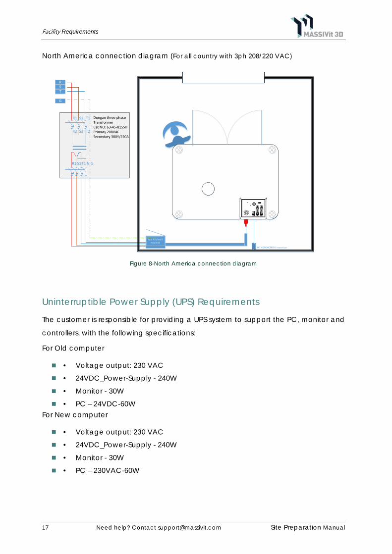
North America connection diagram (For all country with 3ph 208/220 VAC)
Figure 8-North America connection diagram
Uninterruptible Power Supply (UPS) Requirements
The customer is responsible for providing a UPS system to support the PC, monitor and
controllers, with the following specifications:
For Old computer
• Voltage output: 230 VAC
• 24VDC_Power-Supply - 240W
• Monitor - 30W
• PC – 24VDC-60W For New computer
• Voltage output: 230 VAC
• 24VDC_Power-Supply - 240W
• Monitor - 30W
• PC – 230VAC-60W
RST
R1
R2
S1
S2
T1
T2
N
G
Air connection European type
R1 S1T1 G
Dongan three phase TransformerCat NO: 63-45-815SHPrimary 208VACSecondary 380Y/220Δ

Facility Requirements
18 Need help? Contact [email protected] Site Preparation Manual
AC Cable
The Customer is responsible for providing a power cable with connector to fit gland
type of PG29 or M32 to connect the printer to wall mounted power distribution unit PDU
(Supplied with the printer).
Grounding
The MASSIVIT 1800 printer must be connected to a special ground line in order to protect
the operator and the printer and minimize electrostatic affects.
The following grounding requirements must be fulfilled:
Ground impedance must be less than 0.1 ohms.
Pneumatic Requirements
The supply of compressed air to the Massivit 1800 printer may be by way of a central air
supply system, or with the use of a dedicated air compressor. In either situation, a wall-
mounted air outlet will be required. This should have a quick-coupler fitting and be
located near the MASSIVIT 1800 printer.
Figure 9-MASSIVit 1800 Air line
Air Compressor
Operating Pressure: 6 - 8 bars (88.2 - 117.6 psi) at Minimum of 1.2 liter/min (43 CFM).
Air Dryer
We suggest to customers who have moisture in airline consider installing an air dryer, Air
dryer requirements:
Operating Pressure: 6 - 8 bars (88.2 - 117.6 psi) at Minimum of 1.2 liter/min (43 CFM) Dew
point: 2°C (35.6°F).
Air
pre
ssur
e lin
e Ø
1/2”
Wa
ter T
rap
Oil
Sep
ara
tor
Air Dryer
Air compressor
6-8
Bar,
43 C
FM
Facility Requirements
19 Need help? Contact [email protected] Site Preparation Manual
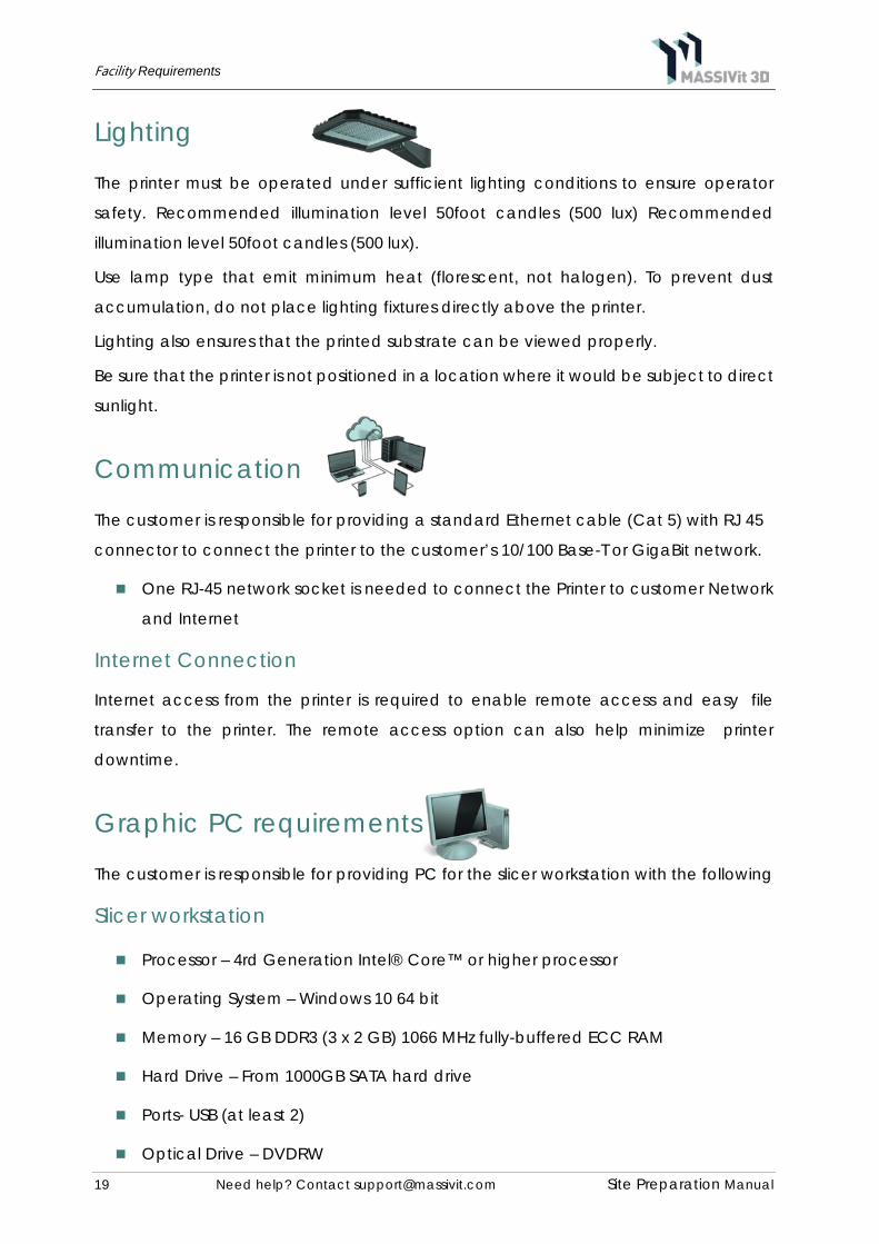
Lighting
The printer must be operated under sufficient lighting conditions to ensure operator
safety. Recommended illumination level 50foot candles (500 lux) Recommended
illumination level 50foot candles (500 lux).
Use lamp type that emit minimum heat (florescent, not halogen). To prevent dust
accumulation, do not place lighting fixtures directly above the printer.
Lighting also ensures that the printed substrate can be viewed properly.
Be sure that the printer is not positioned in a location where it would be subject to direct
sunlight.
Communication
The customer is responsible for providing a standard Ethernet cable (Cat 5) with RJ 45
connector to connect the printer to the customer’s 10/100 Base-T or GigaBit network.
One RJ-45 network socket is needed to connect the Printer to customer Network
and Internet
Internet Connection
Internet access from the printer is required to enable remote access and easy file
transfer to the printer. The remote access option can also help minimize printer
downtime.
Graphic PC requirements
The customer is responsible for providing PC for the slicer workstation with the following
Slicer workstation
Processor – 4rd Generation Intel® Core™ or higher processor
Operating System – Windows 10 64 bit
Memory – 16 GB DDR3 (3 x 2 GB) 1066 MHz fully-buffered ECC RAM
Hard Drive – From 1000GB SATA hard drive
Ports- USB (at least 2)
Optical Drive – DVDRW
Facility Requirements
20 Need help? Contact [email protected] Site Preparation Manual
Video Card – 1GB RAM Graphic Board with 1280 x 1024, min of 16-bit color.
*Graphics board & drivers must be installed prior Slicer installation
It is recommended to use 2 network boards:
o 1GB BASE-T adapter (for the network connection)
o 1GB Ethernet adapter (for direct connection to the machine) File
Preparation Software
Operating system-
o Windows 7 or 10 Professional (64 bit) SP1
o Insure updated USB drivers (last update to the slicer installation date),
according to the computer manufacture.
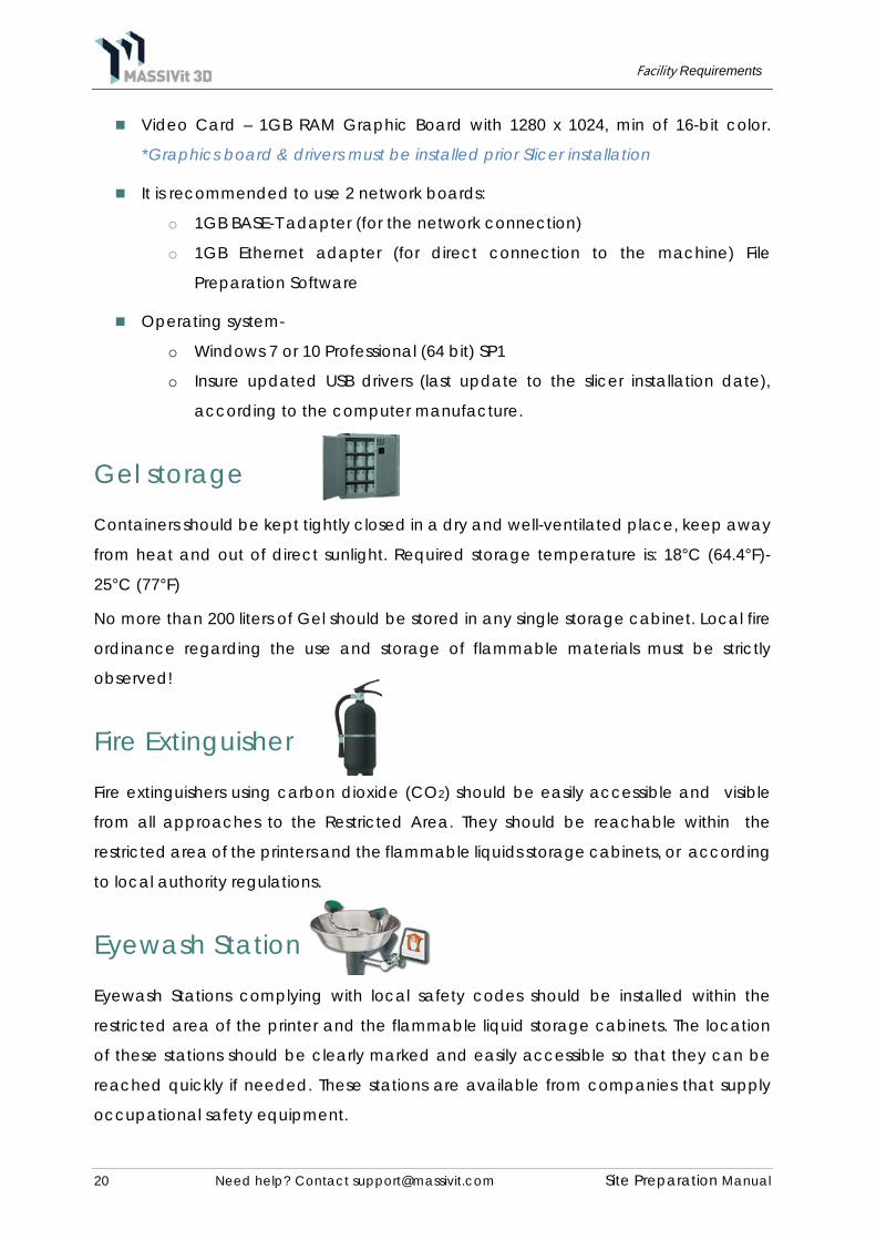
Gel storage
Containers should be kept tightly closed in a dry and well-ventilated place, keep away
from heat and out of direct sunlight. Required storage temperature is: 18°C (64.4°F)-
25°C (77°F)
No more than 200 liters of Gel should be stored in any single storage cabinet. Local fire
ordinance regarding the use and storage of flammable materials must be strictly
observed!
Fire Extinguisher
Fire extinguishers using carbon dioxide (CO2) should be easily accessible and visible
from all approaches to the Restricted Area. They should be reachable within the
restricted area of the printers and the flammable liquids storage cabinets, or according
to local authority regulations.
Eyewash Station
Eyewash Stations complying with local safety codes should be installed within the
restricted area of the printer and the flammable liquid storage cabinets. The location
of these stations should be clearly marked and easily accessible so that they can be
reached quickly if needed. These stations are available from companies that supply
occupational safety equipment.
Appendix A: Site Preparation Check List
21 Need help? Contact [email protected] Site Preparation Manual
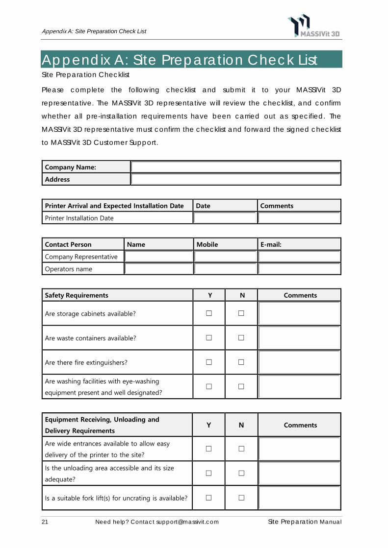
Appendix A: Site Preparation Check List Site Preparation Checklist
Please complete the following checklist and submit it to your MASSIVit 3D
representative. The MASSIVit 3D representative will review the checklist, and confirm
whether all pre-installation requirements have been carried out as specified. The
MASSIVit 3D representative must confirm the checklist and forward the signed checklist
to MASSIVit 3D Customer Support.
Company Name: Address
Printer Arrival and Expected Installation Date Date Comments
Printer Installation Date
Contact Person Name Mobile E-mail:
Company Representative Operators name
Safety Requirements Y N Comments
Are storage cabinets available? ☐ ☐
Are waste containers available? ☐ ☐
Are there fire extinguishers? ☐ ☐
Are washing facilities with eye-washing
equipment present and well designated? ☐ ☐
Equipment Receiving, Unloading and
Delivery Requirements Y N Comments
Are wide entrances available to allow easy
delivery of the printer to the site? ☐ ☐
Is the unloading area accessible and its size
adequate? ☐ ☐
Is a suitable fork lift(s) for uncrating is available? ☐ ☐

Appendix A: Site Preparation Check List
22 Need help? Contact [email protected] Site Preparation Manual
Equipment Receiving, Unloading and
Delivery Requirements Dimensions [M/F] Comments
Provide 1st entrances if needed H-W-L [M/F]
Provide 2nd entrances if needed H-W-L [M/F]
Provide 3rd entrances if needed H-W-L [M/F]
Provide final room entrances Final H-W-L [M/F]
Minimum lift weight in printer entrance path
[KG]
Site Preparation Y N Comments
Sufficient workspace clearance has been allowed
around the printer ☐ ☐
Have the required power outlets been installed? ☐ ☐
Input Voltage has been properly installed? ☐ ☐
If a transformer is required, has one been
properly installed? ☐ ☐
Has main power ready to be
connected? ☐ ☐
Is there a UPS (Uninterrupted Power Supply) for
the Printer ☐ ☐
Is there a proper design workstation (PC)? ☐ ☐
Is the flooring capable of safely supporting and
evenly distributing the weight of the printer? ☐ ☐
Has the floor surface been properly leveled? ☐ ☐
Positioning of the equipment has been determined
☐ ☐

Appendix A: Site Preparation Check List
23 Need help? Contact [email protected] Site Preparation Manual
Environmental Requirements Y N Comments
Have all temperature and humidity (air
conditioning) requirements been satisfactorily
met?
☐ ☐
Has the site been equipped with an air
compressor and air dryer per required specs? ☐ ☐
Is the site ready for operation? ☐ ☐
Has a suitable air evacuation unit been installed? ☐ ☐
3D Operators Experience Y N Comments
Is there is a dedicated Operator? ☐ ☐
Is there is a dedicated Application designer? ☐ ☐
Is there is 3D modeling experience in your site?
☐ ☐
Do you have 3D SW in your site? ☐ ☐
Do you need MASSIVit Application Web training
prior Installation on? ☐ ☐
General Comments:

Appendix A: Site Preparation Check List
24 Need help? Contact [email protected] Site Preparation Manual
By signing this form, I declare all above information is true and correct .
I hereby acknowledge that any additional expenses resulting from discrepancies
between this document and the status onsite may result in the charging of said
expenses to the customer.
Site Manager Name
Site Manager Signature:
Date:
Please send the signed document to [email protected] including your Site name.


![Untitled-1 [] 500N.pdf · WeP Solutions Limited e-mail: wep.enquiry@wepindia.com ersion-3.0/May/2014 POS Printers Dot Matrix Printers Laser Printers Billing Printers Line Matrix](https://img.pdfslide.net/doc/110x75/5b03bf717f8b9a8c688ca127/untitled-1-500npdfwep-solutions-limited-e-mail-wepenquirywepindiacom-ersion-30may2014.jpg)