Embed Size (px)
Citation preview
Master in Advanced Power Electrical Engineering
© Copyright 2005
Techno-economic aspects of power systems
Ronnie BelmansDirk Van Hertem
Stijn Cole

© Copyright 2005
• Lesson 1: Liberalization
• Lesson 2: Players, Functions and Tasks
• Lesson 3: Markets
• Lesson 4: Present generation park
• Lesson 5: Future generation park
• Lesson 6: Introduction to power systems
• Lesson 7: Power system analysis and control
• Lesson 8: Power system dynamics and security
• Lesson 9: Future grid technologies: FACTS and HVDC
• Lesson 10: Distributed generation

© Copyright 2005
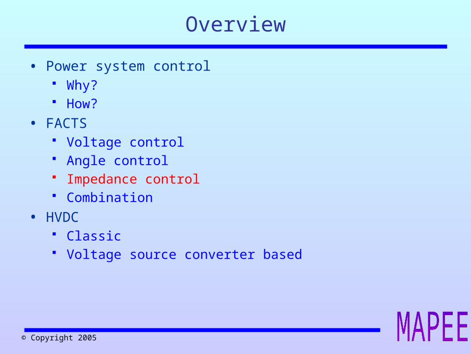
• Power system control Why? How?
• FACTS Voltage control Angle control Impedance control Combination
• HVDC Classic Voltage source converter based
Overview

© Copyright 2005
Power transfer through a lineHow?
• Active power transfer: Phase angle Problems with long distance transport
o Phase angle differences have to be limitedo Power transfer ==> power losses
• Reactive power transfer Voltage amplitude Problems:
o Voltage has to remain within limitso Only locally controlled
By changing voltage, impedance or phase angle, the power flow can be altered ==> FACTS

© Copyright 2005
Power transfer through a line:
distanceX ~
1 2
2
1 1 2
P = sin
Q = cos
U Uδ
X
U U Uδ
X X
Power transfer through a lineTheory

© Copyright 2005
UK
F CH
IE
B
D35 %
A
NL
18 %13 %
8 %
34 %34 %
20 %
10 % 3 %
11 %
European power flowstransport France ==> Germany
© Copyright 2005
Overview
• Power system control Why? How?
• FACTS Voltage control Angle control Impedance control Combination
• HVDC Classic Voltage source converter based
© Copyright 2005
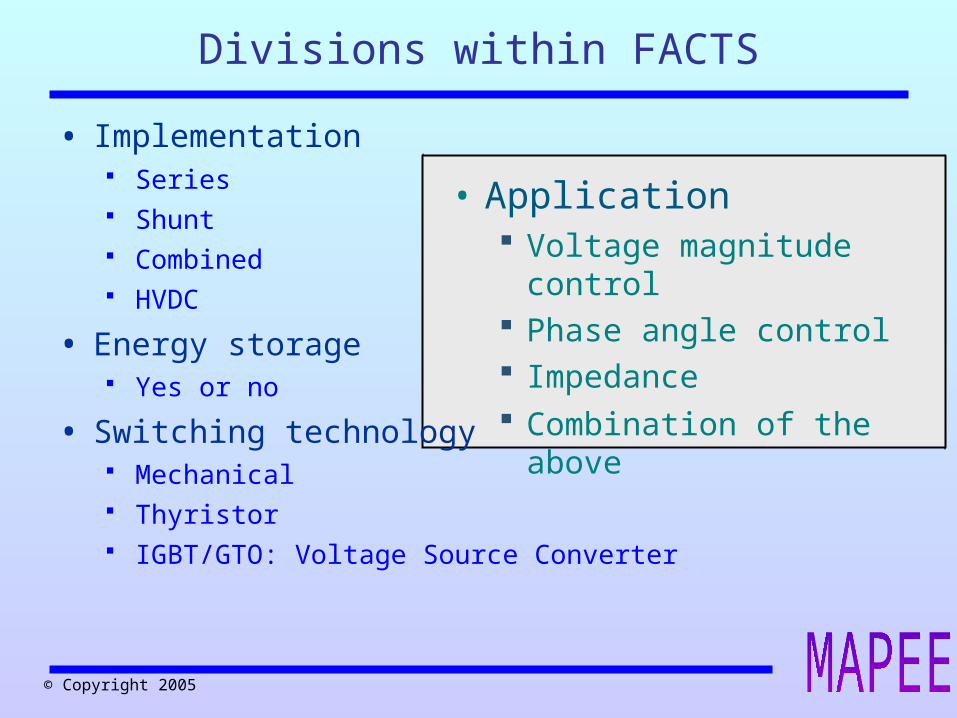
• Application Voltage magnitude control Phase angle control Impedance Combination of the above
Divisions within FACTS
• Implementation Series Shunt Combined HVDC
• Energy storage Yes or no
• Switching technology Mechanical Thyristor IGBT/GTO: Voltage Source Converter

© Copyright 2005
Application domain FACTS
Transmission level• Power flow control
Regulation of slow power flow variations
• Voltage regulation Local control of voltage profile
• Power system stability improvement Angle stability
o Caused by large and/or small perturbations Voltage stability
o Short and long term
© Copyright 2005
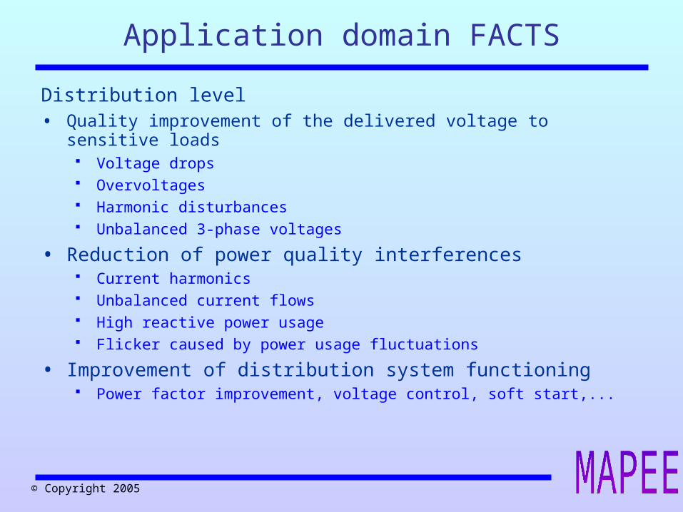
Application domain FACTS
Distribution level• Quality improvement of the delivered voltage to sensitive loads
Voltage drops Overvoltages Harmonic disturbances Unbalanced 3-phase voltages
• Reduction of power quality interferences Current harmonics Unbalanced current flows High reactive power usage Flicker caused by power usage fluctuations
• Improvement of distribution system functioning Power factor improvement, voltage control, soft start,...

© Copyright 2005
1 2
21 1 2
P= sin
Q= cos
U Uδ
X
U U Uδ
X X
Voltage magnitude adjustment

© Copyright 2005
Different configurations:
Thyristor Controlled Reactor (TCR)
Thyristor Switched Capacitor (TSC)
Thyristor Switched Reactor (TSR)
Mechanical Switched Capacitor (MSC)
Mechanical Switched Reactor (MSR)
Often a combination
Static Var Compensation - SVC
• Variable thyristor controlled shunt impedance Variable reactive power source Provides ancillary services
o Maintains a smooth voltage profileo Increases transfer capability o Reduces losses
Mitigates active power oscillations Controls dynamic voltage swings under various system
conditions

© Copyright 2005
STATic COMpensatorSTATCOM
• Shunt voltage injection Voltage Source Convertor (VSC) Low harmonic content Very fast switching More expensive than SVC Energy storage? (SMES, supercap)

© Copyright 2005
Price comparison voltage regulation
• Cost of voltage regulation capabilities dependent on: Speed Continuous or discrete regulation Control application
• 300 MVAr – 150 kV Capacitor banks: 6 M€ (min) SVC: 9 à 17 M€ (# periods) Statcom: 31 M€ (ms)

© Copyright 2005
1 2
21 1 2
P= sin
Q= cos
U Uδ+α
X
U U Uδ+α
X X
Phase shifting transformer Voltage angle adjustment.

© Copyright 2005
1 2 sinPST
U UP= δ+α
X + X
Phase shifting transformer
• Allows for some control over active power flows
• Mechanically switched ==> minutes
© Copyright 2005
U
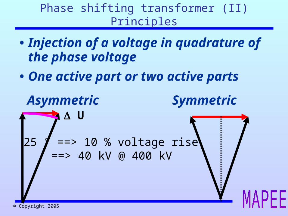
25 ° ==> 10 % voltage rise ==> 40 kV @ 400 kV
Phase shifting transformer (II)Principles
• Injection of a voltage in quadrature of the phase voltage
• One active part or two active parts
Asymmetric Symmetric

© Copyright 2005
2
1'
311
2
32'3'3'
Voltages over coils on the same transformer leg are in phase
Phase shifting transformer (III)One active part
• Series voltage injection
• In quadrature to the phase voltage
• One active part: low power/low voltage (high shortcircuit currents at low angle)

© Copyright 2005
Phase shifting transformerRegulating
• Changing injected voltage: Tap changing transformer Slow changing of tap position: ½ min
• Control of the injected voltage: Centrally controlled calculations Updates every 15 minutes Often remote controlled Can be integrated in WAMS/WACS
system

© Copyright 2005
GGGGGGGG
GGG
A B
C
1018 MW
Flow of A to B gets distributed
according to the impedances
173.5 MW 170.4 MW
344.3 MW
800 MW800 MW
500 MW
500 MW
1000 MW
losses: 18 MW
Slack bus
Phase shifter influenceBase case

© Copyright 2005
GGGGGGGG
GGG
A B
C
1024.6 MW
Flow of A to B is taken mostly by
line A-B
33 MW32.8 MW
491.8 MW
800 MW800 MW
500 MW
500 MW
1000 MW
losses: 24.6 MW
15 °
Phase shifter influence1 phase shifter placed

© Copyright 2005
GGGGGGGG
GGG
A B
C
1034 MW
Overcompensation causes a
circulation current
41.4 MW42.3 MW
580 MW
800 MW800 MW
500 MW
500 MW
1000 MW
losses: 34 MW
30 °
Phase shifter influence1 phase shifter placed: overcompensation

© Copyright 2005
GGGGGGGG
GGG
A B
C
1052.3 MW
The phase shifting transformers can
cancel their effects
238.4 MW221 MW
313.9 MW
800 MW800 MW
500 MW
500 MW
1000 MW
losses: 52.3 MW
15 °
15 °
Phase shifter influence2 phase shifters: cancelling

© Copyright 2005
GGGGGGGG
GGG
A B
C
1052.3 MW
238.4 MW221 MW
313.9 MW
800 MW800 MW
500 MW
500 MW
1000 MW
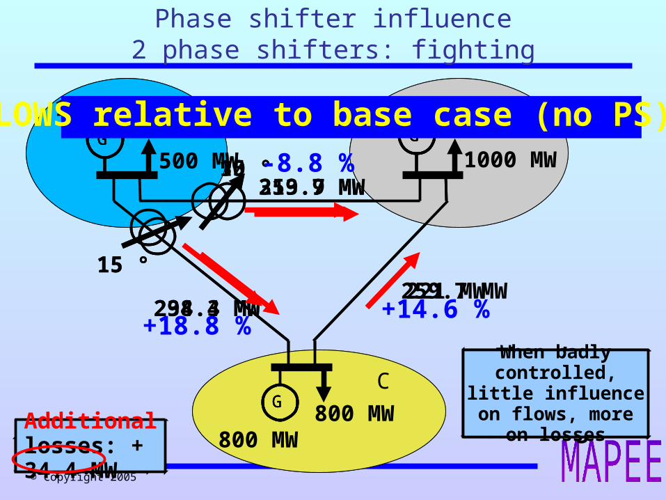
Additional losses: + 34.4 MW
15 °
15 ° -8.8 %
+14.6 %+18.8 %
FLOWS relative to base case (no PS)
When badly controlled, little
influence on flows, more on losses
Phase shifter influence2 phase shifters: cancelling
© Copyright 2005
GGGGGGGG
GGG
A B
C
1054 MW
The phase shifting transformers can
`fight'
294.3 MW259.7 MW
259.7 MW
800 MW800 MW
500 MW
500 MW
1000 MW
losses: 54 MW
15 °
30 °
GGGGGGGG
GGG
A B
C
1052.3 MW
238.4 MW221 MW
313.9 MW
800 MW800 MW
500 MW
500 MW
1000 MW
Additional losses: + 34.4 MW
15 °
15 ° -8.8 %
+14.6 %+18.8 %
FLOWS relative to base case (no PS)
When badly controlled, little
influence on flows, more on losses
Phase shifter influence2 phase shifters: fighting
© Copyright 2005
GGGGGGGG
GGG
A B
C
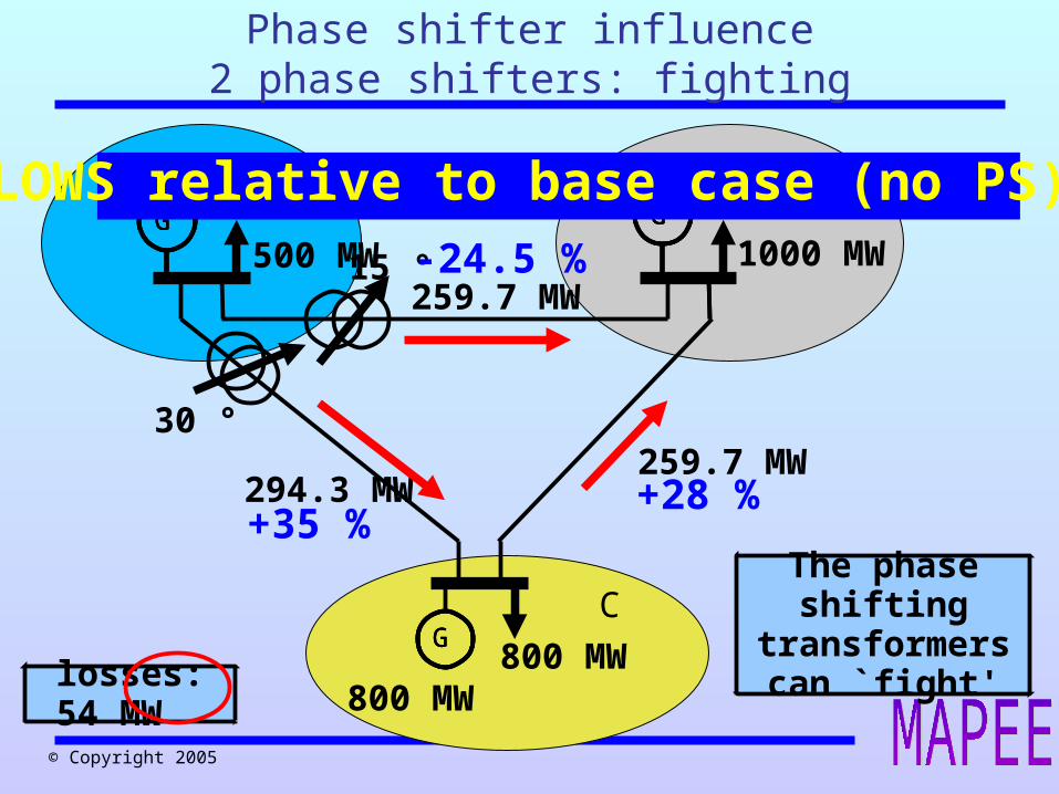
1054 MW
The phase shifting transformers can
`fight'
294.3 MW259.7 MW
259.7 MW
800 MW800 MW
500 MW
500 MW
1000 MW
losses: 54 MW
30 °
15 °
+35 %
-24.5 %
+28 %
FLOWS relative to base case (no PS)
Phase shifter influence2 phase shifters: fighting

© Copyright 2005
Phase shifters in Belgium
• Zandvliet – Zandvliet
• Meerhout – Maasbracht (NL)
• Gramme – Maasbracht (NL) 400 kV +/- 25 ° no load 1400 MVA 1.5 ° step (34 steps)
• Chooz (F) – Monceau B 220/150 kV +10/-10 * 1.5% V (21 steps) +10/-10 * 1,2° (21 steps) 400 MVA
© Copyright 2005
• Power system control Why? How?
• FACTS Voltage control Angle control Impedance control Combination
• HVDC Classic Voltage source converter based
Overview

© Copyright 2005
1 2
21 1 2
P= sin
Q= cos
U Uδ
X
U U Uδ
X X
Series compensationLine impedance adjustment
© Copyright 2005
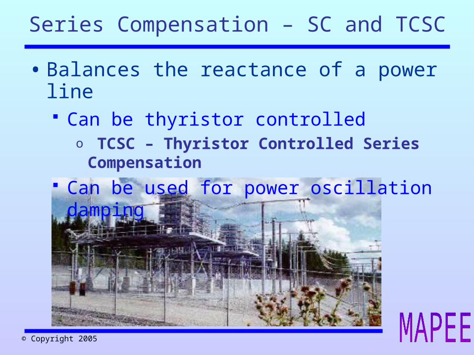
Series Compensation – SC and TCSC
• Balances the reactance of a power line Can be thyristor controlled
o TCSC – Thyristor Controlled Series Compensation
Can be used for power oscillation damping

© Copyright 2005
1 2
21 1 2
P= sin
Q= cos
U Uδ
X
U U Uδ
X X
ΔU
Unified Power Flow Controller Ultimate flow control

© Copyright 2005
UPFC - Unified Power Flow Controller
Voltage source converter-based (no thyristors)
o Superior performance
o Versatility
o Higher cost ~25%
Concurrent control of
o Line power flows
o Voltage magnitudes
o Voltage phase angles
Benefits in steady state and emergency situations
o Rapid redirection power flows and/or damping of power oscillations

© Copyright 2005
P shunt=− P series
21
Unified Power Flow Controller (II)Ultimate flow control
• Two voltage source converters
• Series flow control
• Parallel voltage control
• Very fast response time Power oscillation damper
© Copyright 2005
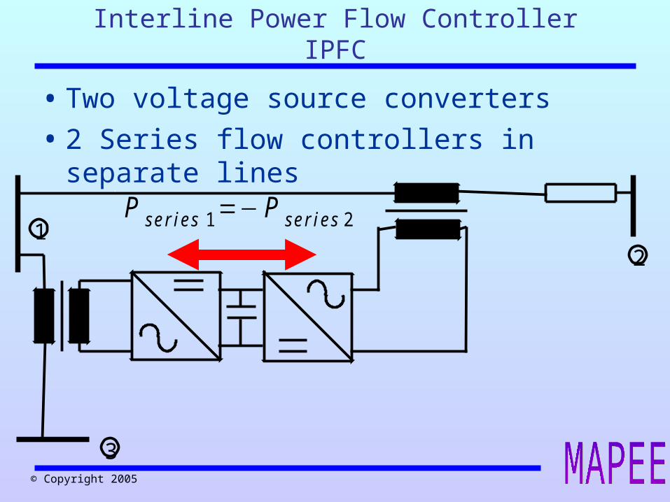
P series 1=− P series 21
3
2
Interline Power Flow ControllerIPFC
• Two voltage source converters
• 2 Series flow controllers in separate lines

© Copyright 2005
Overview
• Power system control Why? How?
• FACTS Voltage control Angle control Impedance control Combination
• HVDC Classic Voltage source converter based

© Copyright 2005
DC DCP=U I
• High voltage DC connection No reactive losses
o No stability distance limitationo No limit to underground cable lengtho Lower electrical losses
2 cables instead of 3 Synchronism is not needed
o Connecting different frequencieso Asynchronous grids (UCTE – UK)o Black start capability? (New types, HVDC light)
Power flow (injection) can be fully controlled
• Renewed attention of the power industry
High Voltage Direct CurrentHVDC

© Copyright 2005
History of HVDC
© Copyright 2005
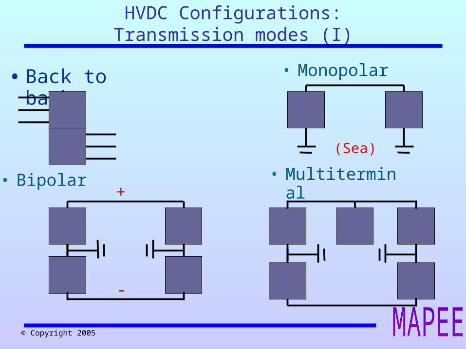
• Back to back
• Multiterminal• Bipolar
• Monopolar
(Sea)
+
-
HVDC Configurations:Transmission modes (I)

© Copyright 2005
HVDC Configurations:Transmission modes (II)
© Copyright 2005
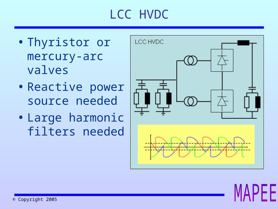
LCC HVDC
• Thyristor or mercury-arc valves
• Reactive power source needed
• Large harmonic filters needed

© Copyright 2005
VSC HVDC
• IGBT valves
• P and Q (or U) control
• Can feed in passive networks
• Smaller footprint
• Less filters needed
© Copyright 2005
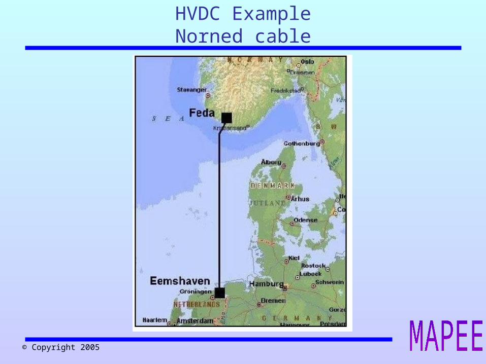
HVDC ExampleNorned cable
© Copyright 2005
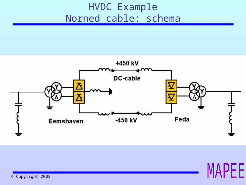
HVDC ExampleNorned cable: schema

© Copyright 2005
HVDC ExampleNorned cable: sea cable

© Copyright 2005
HVDC ExampleGarabi back to back
© Copyright 2005
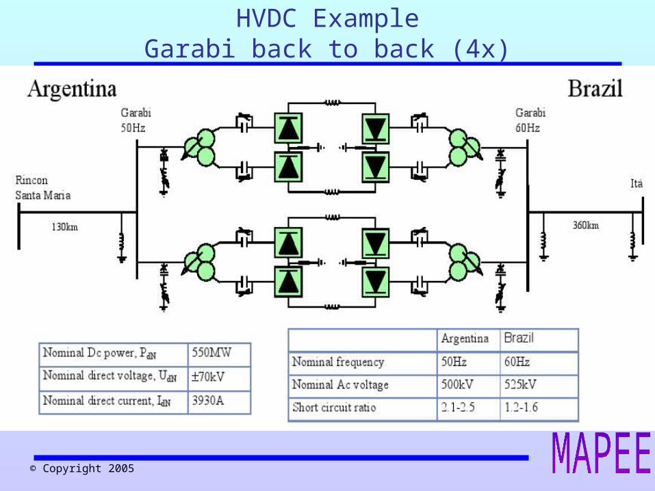
HVDC ExampleGarabi back to back (4x)

© Copyright 2005
• Commissioning year:2002
• Power rating: 220 MW AC
• Voltage:132/220 kV
• DC Voltage:+/- 150 kV
• DC Current: 739 A
• Length of DC cable:2 x 180 km
VSC HVDCexample: Murray link

© Copyright 2005
VSC HVDCexample: Troll
• Commissioning year: 2005
• Power rating: 2 x 42 MW AC Voltage:132 kV at Kollsnes, 56 kV at Troll
• DC Voltage: +/- 60 kV
• DC Current: 350 A• Length of DC cable:4
x 70 km

© Copyright 2005
HVDC: Current sizes
LCC VSC
Voltage (kV) ±600 ±150
Current (kA) 3.93 1.175
Power (MW) 2 x 3150 350
Length (km) 1000 2 x 180

© Copyright 2005
References
• Understanding Facts: Concepts and Technology of Flexible AC Transmission Systems, Narain G. Hingorani, Laszlo Gyugyi
• Flexible AC transmission systems, Song & Johns
• Thyristor-based FACTS controllers for electrical transmission systems, Mathur Vama
• Power system stability and control, Phraba Kundur, 1994, EPRI


![[by Jan Melkebeek, R. Belmans] COMPEL - Selected (Bookos.org)](https://img.pdfslide.net/doc/110x75/55cf9a65550346d033a18485/by-jan-melkebeek-r-belmans-compel-selected-bookosorg.jpg)