Embed Size (px)
Citation preview

BEOLINK
Master Link Handbook

MASTER LINK

MASTER LINK
PREFACE
This handbook deals with Bang & Olufsen’s BeoLink (Master Link), payingspecial attention to the installation requirements applying to it.Consequently, this handbook is especially targeted on dealers andinstallers.
Any product, for example a stereo system, a PC, a natural gas system, etc.,that has to be incorporated into a network needs to have certainrequirements satisfied by the surroundings in connection with itsinstallation. These requirements must ensure the optimal operation of thesystem after installation.
The same applies to Bang & Olufsen’s BeoLink. Although therequirements are not many, it is essential that they be known sincecompliance with the basic requirements often determines whether or notthe system is able to operate once the installation has been completed.
The handbook gives a brief and precise introduction to the basic rulesthat must be observed in connection with a BeoLink installation, and itdescribes how compatibility is achieved between Master Link productsand Master Control Link products.
The handbook has been designed partly as a reference book but theentire handbook should be read in order to obtain the total overview.Only then will it serve its purpose as a reference book.

MASTER LINK
CONTENTS
READING INSTRUCTIONSHow should I read this handbook
GENERAL DESCRIPTIONWhat is a BeoLink system/Master Link system, and what can it do for me?
PRODUCT DESCRIPTIONDescription of BeoLab 3500, BeoLab 2000 and BeoLink boxes
SETUPSDescription of recommended Master Link setups, compatibility setups,special setups and option programming
DIMENSIONINGDescription of how much cable may be used
INSTALLATION TYPESDescription of various installation types
INSTALLATION TIPSPractical advice for use in connection with installation
TECHNICAL DESCRIPTIONDescription of various cables which are typically used
TROUBLESHOOTING GUIDEWhat could be wrong when the system will not operate?
GLOSSARYDescription of specific words and abbreviations
ACCESSORIES LIST
FOR NOTES
1
2
4
11
22
23
26
29
32
35
39
45

MASTER LINK
READING INSTRUCTION
This handbook employs various symbols to illustrate audio products, videoproducts and speakers. Unless otherwise specified in the text, thesesymbols merely have to be understood as covering one of these productareas and not as the specific product which the illustration may depict.
Since the handbook is focusing particularly on the basic rules inconnection with the installation of the systems, variables which arespecific to particular products have been omitted to the greatest possibleextent. This means that the handbook will always be relevant inconnection with installation of the Master Link; both with regard toproducts launched prior to the publication of the handbook and productsthat will be launched later. The basic rules applying to the Master Linkwill always be the same.
If information specific to a particular product is required, please seeBang & Olufsen’s Product Configuration Guide.
1
MASTER LINK2
GENERAL DESCRIPTION
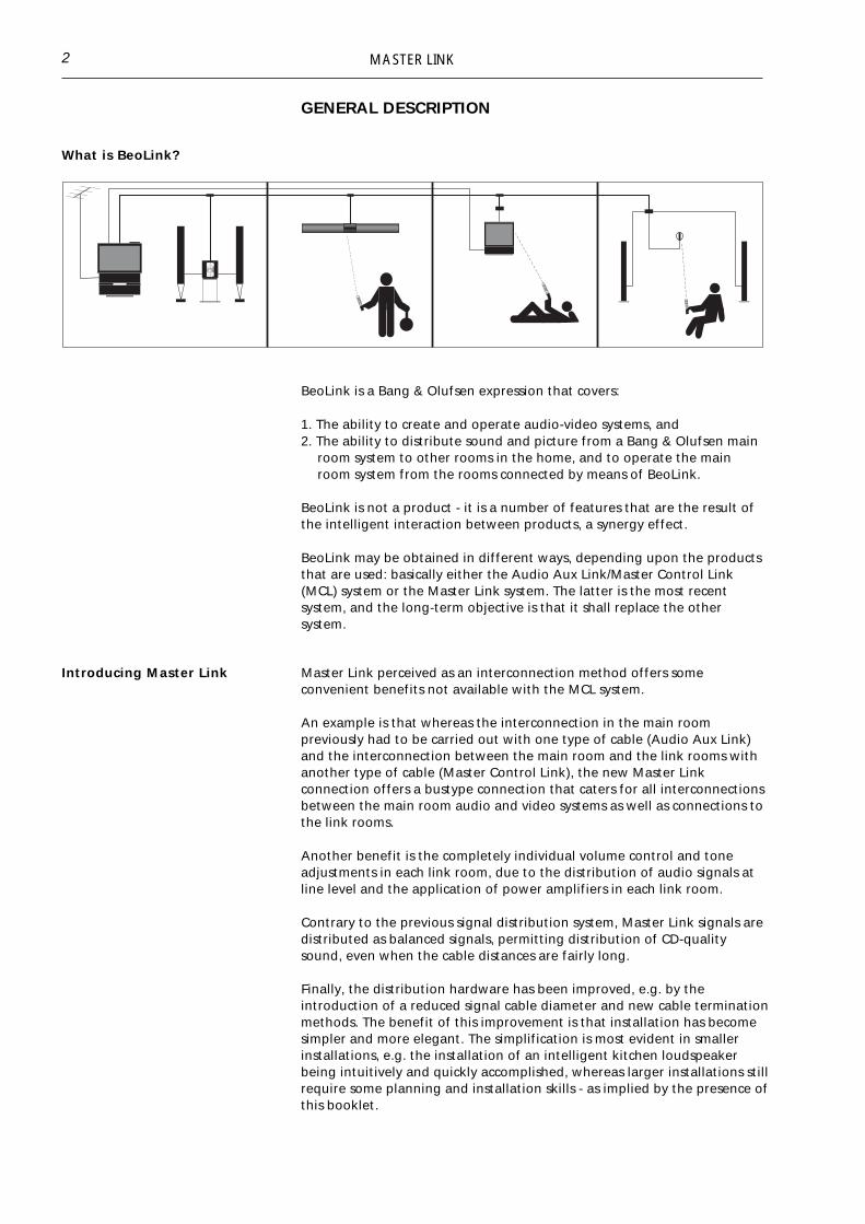
What is BeoLink?
BeoLink is a Bang & Olufsen expression that covers:
1. The ability to create and operate audio-video systems, and2. The ability to distribute sound and picture from a Bang & Olufsen main
room system to other rooms in the home, and to operate the mainroom system from the rooms connected by means of BeoLink.
BeoLink is not a product - it is a number of features that are the result ofthe intelligent interaction between products, a synergy effect.
BeoLink may be obtained in different ways, depending upon the productsthat are used: basically either the Audio Aux Link/Master Control Link(MCL) system or the Master Link system. The latter is the most recentsystem, and the long-term objective is that it shall replace the othersystem.
Introducing Master Link Master Link perceived as an interconnection method offers someconvenient benefits not available with the MCL system.
An example is that whereas the interconnection in the main roompreviously had to be carried out with one type of cable (Audio Aux Link)and the interconnection between the main room and the link rooms withanother type of cable (Master Control Link), the new Master Linkconnection offers a bustype connection that caters for all interconnectionsbetween the main room audio and video systems as well as connections tothe link rooms.
Another benefit is the completely individual volume control and toneadjustments in each link room, due to the distribution of audio signals atline level and the application of power amplifiers in each link room.
Contrary to the previous signal distribution system, Master Link signals aredistributed as balanced signals, permitting distribution of CD-qualitysound, even when the cable distances are fairly long.
Finally, the distribution hardware has been improved, e.g. by theintroduction of a reduced signal cable diameter and new cable terminationmethods. The benefit of this improvement is that installation has becomesimpler and more elegant. The simplification is most evident in smallerinstallations, e.g. the installation of an intelligent kitchen loudspeakerbeing intuitively and quickly accomplished, whereas larger installations stillrequire some planning and installation skills - as implied by the presence ofthis booklet.

MASTER LINK 3
BeoLink distribution covers the ability to distribute both audio and videosignals. In the Master Link system audio and control signals aredistributed by means of one single cable, whereas the distribution ofvideo signals requires a coaxial cable network. Only BeoLink compatibleproducts can be fully integrated in a BeoLink system, but previous systemproducts may be integrated to a limited extent, as described in thechapter on Compatibility setups, page 17.
MASTER LINK
PRODUCT DESCRIPTION
Below you will find a description of the individual elements included withthe Master Link products as well as their scope of application.
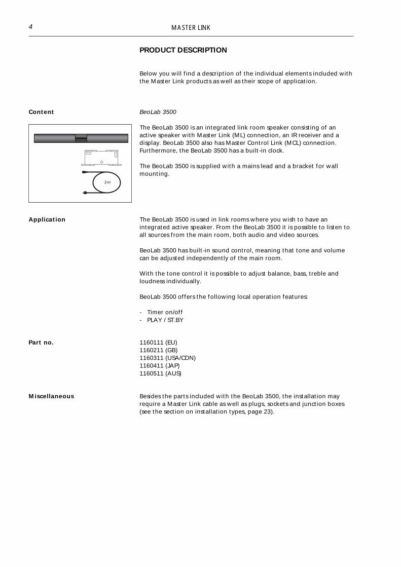
Content BeoLab 3500
The BeoLab 3500 is an integrated link room speaker consisting of anactive speaker with Master Link (ML) connection, an IR receiver and adisplay. BeoLab 3500 also has Master Control Link (MCL) connection.Furthermore, the BeoLab 3500 has a built-in clock.
The BeoLab 3500 is supplied with a mains lead and a bracket for wallmounting.
4
Application The BeoLab 3500 is used in link rooms where you wish to have anintegrated active speaker. From the BeoLab 3500 it is possible to listen toall sources from the main room, both audio and video sources.
BeoLab 3500 has built-in sound control, meaning that tone and volumecan be adjusted independently of the main room.
With the tone control it is possible to adjust balance, bass, treble andloudness individually.
BeoLab 3500 offers the following local operation features:
- Timer on/off- PLAY / ST.BY
Part no. 1160111 (EU)1160211 (GB)1160311 (USA/CDN)1160411 (JAP)1160511 (AUS)
Miscellaneous Besides the parts included with the BeoLab 3500, the installation mayrequire a Master Link cable as well as plugs, sockets and junction boxes(see the section on installation types, page 23).

MASTER LINK
Content BeoLab 2000
BeoLab 2000 is an integrated link room speaker consisting of an activespeaker with Master Link (ML) connection, an IR receiver and close-upoperation.
The BeoLab 2000 is supplied with a mains lead and a bracket for wallmounting.
Application The BeoLab 2000 is used in link rooms where you wish to have anintegrated active speaker. From the BeoLab 2000 it is possible to listen toall sources from the main room, both audio and video sources.
BeoLab 2000 has built-in volume control, meaning that volume can beadjusted independently of the main room.
BeoLab 2000 offers the following close-up operation features:
- Timer on/off- PLAY / ST.BY- Volume up and down- Close-up selection of Radio, CD or Tape- Step-button for switching programs or tracks
5
Part no. 1164129 (EU)1164229 (GB)1164329 (USA/CDN)1164429 (JAP)1164529 (AUS)
Miscellaneous Besides the parts included with the BeoLab 2000, the installation requiresa Master Link cable as well as plugs, sockets and junction boxes (see thesection on installation types, page 23).
3 m
BANG & OLUFSEN
MASTER LINK
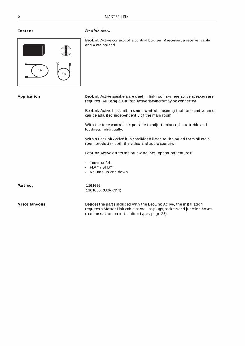
Content BeoLink Active
BeoLink Active consists of a control box, an IR receiver, a receiver cableand a mains lead.
Application BeoLink Active speakers are used in link rooms where active speakers arerequired. All Bang & Olufsen active speakers may be connected.
BeoLink Active has built-in sound control, meaning that tone and volumecan be adjusted independently of the main room.
With the tone control it is possible to adjust balance, bass, treble andloudness individually.
With a BeoLink Active it is possible to listen to the sound from all mainroom products - both the video and audio sources.
BeoLink Active offers the following local operation features:
- Timer on/off- PLAY / ST.BY- Volume up and down
6
Part no. 11616661161866, (USA/CDN)
Miscellaneous Besides the parts included with the BeoLink Active, the installationrequires a Master Link cable as well as plugs, sockets and junction boxes(see the section on installation types, page 23).

MASTER LINK
Content BeoLink Passive
BeoLink Passive consists of a control box, an IR receiver, a receiver cableand a mains lead.
Application BeoLink Passive speakers are used in link rooms where passive speakersare required. All Bang & Olufsen passive speakers may be connected.
BeoLink Passive has built-in sound control, meaning that tone and volumecan be adjusted independently of the main room.
With the tone control it is possible to adjust balance, bass, treble andloudness individually.
With a BeoLink Passive it is possible to listen to the sound from all mainroom products - both the video and audio sources.
BeoLink Passive offers the following local operation features:
- Timer on/off- PLAY / ST.BY- Volume up and down
7
Part no.
Miscellaneous Besides the parts included with the BeoLink Passive, the installationrequires a Master Link cable as well as plugs, sockets and junction boxes(see the section on installation types, page 23).
1165566 (AUS)1165666 (EU)1165766 (GB)1165866 (USA/CDN)

MASTER LINK
Content BeoLink Video
BeoLink Video consists of a control box, a mains lead and a datalink cable.
Apart from this you need an coaxial cable from the HF outlet of the videosystem in the main room. This cable is connected to the aerial input of thelink room TV.
Application BeoLink Video is used in link rooms where both sound and picture arerequired via a Bang & Olufsen TV set.
With BeoLink Video it is possible to use all the sources in the main room.In particular it is possible to operate SAT and V.TAPE but it is furtherpossible to watch a decoded programme from the TV set in the mainroom. In addition, it is possible to operate all audio sources, therebyusing the speakers in Bang & Olufsen’s TV sets for obtaining audio sound.If you want even greater sound in the room you can connect Bang &Olufsen’s active speakers to the TV set.
BeoLink Video is connected to the TV set by means of the 7-pin datalinkcable and to the main room with a Master Link cable. Apart from this anaerial installation is needed (see page 24).
8
Part no. 1161566
Miscellaneous Besides the parts included with the BeoLink Video, the installationrequires a Master Link cable as well as plugs, sockets and junction boxes(see the section on installation types, page 23).

MASTER LINK
Content BeoLink Converter
BeoLink Converter consists of a control box and a mains lead.
1.5 m
Application BeoLink Converter is used when audio and video products with MasterLink and Audio Aux Link (datalink) have to be interconnected.
BeoLink Converter can be used in conjunction with both a video and anaudio master. BeoLink Converter features autoconfiguration, meaningthat it is able to detect automatically whether it is installed in a MasterLink audio or in a Master Link video system. Configuration takes placewhen it is connected to the mains.
BeoLink Converter can also be used as ML-driver*, which means that it ispossible to connect e.g. a BeoCenter 2300 via the BeoLink Converter tothe Master Link and thereby distribute sound to all link room products(see page 17).
BeoLink Converter is used in compatibility setups (see the section onrecommended compatibility setups, page 17).
Part no. 11611661161266 (USA/CDN)1161466 (old version)
9
Miscellaneous Besides the parts included with the BeoLink Converter, the installationrequires a Master Link cable as well as plugs, sockets and junction boxes(see the section on installation types, page 23).
*NOTE!BeoLink Converter type no. 1161466 can not be used as ML-driver.

MASTER LINK
1.5 m
Content ML/MCL Converter
ML/MCL Converter consists of a control box and an amplifier.
Application ML/MCL Converter is used where a conversion from Master Link (ML) toMaster Control Link (MCL) is wanted. Such a conversion is required if youwant to maintain the existing Master Control Link system although theaudio system in the main room is replaced with a Master Link driver, forexample a BeoSound Ouverture.
ML/MCL Converter can also be used in conjunction with a Beosystem AV9000 with an AV 9000 Master Panel.
See setups with ML/MCL Converter, page 19.
Part no. 1165066 (AUS)1165166 (EU)1165266 (GB)1165366 (USA/CDN)
Miscellaneous Besides the parts included with the ML/MCL Converter, the installationrequires a Master Link cable as well as plugs, sockets and junction boxes(see the section on installation types, page 23).
10
MASTER LINK
SETUPS
11
Recommended setups An object consisting of several parts can usually only be assembled in oneway if the intended result is to be achieved. For example, a gearbox for acar will not perform optimally according to the specifications if you omitinstalling some of the gearwheels. If you manage to install one gearwheeltoo many, that will most likely cause trouble as well.
The point of the above is that things must be put together in the waythey were designed to, if they are to perform optimally.
The same applies to Bang & Olufsen’s BeoLink. In theory, Bang &Olufsen’s products may be connected in thousands of different ways.Since it would be totally impossible to have an overview of just a fractionof this multitude of connection possibilities, Bang & Olufsen has selectedthe most attractive combinations. These selected combinations are calledrecommended setups. The recommended setups are the ones which arefocused on in connection with product development and service.
When a BeoLink system is configured it is therefore very important thatthis is done in accordance with the recommended setups.
If the recommended setups are not followed, the result may easily be thesame as with the gearbox with too many or too few gearwheels.
Bang & Olufsen services the recommended setups ONLY.
Option programming One of the conditions for the recommended setups to perform optimallyis that the products included in the setup “know” in what kind ofenvironment they are placed.
The actual option programming is executed by pressing a certainsequence of keys on the terminal.
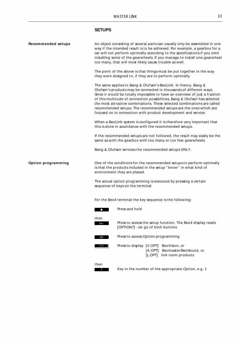
For the Beo4 terminal the key sequence is the following:
Press and hold
thenPress to access the setup function. The Beo4 display reads[OPTION?] - let go of both buttons
Press to access Option-programming
Press to display [V.OPT] BeoVision, or[A.OPT] Beomaster/BeoSound, or[L.OPT] link room products
thenKey in the number of the appropriate Option, e.g. 1

MASTER LINK12
For the Beolink 1000 terminal the key sequence is the following:
Beovision: “digit”
Beomaster/BeoSound: “digit”
Link room products: “digit”
The digit sequence to be used depends on the setup.
Option 0 = No IR receptionOption 1 = Two IR-eyes in the same main roomOption 2 = One IR-eye in the main roomOption 4 = Link room product connected to one or two main room
products in the same roomOption 5 = Two IR-eyes in the same link roomOption 6 = One IR-eye in the link room
It applies to most setups that they are delivered with the correct optionsetting from the factory, and they are thus “ready for use”.
However, since in some situations you may have to work with productsthat have been installed before, e.g. in connection with a house that hasbeen rebuilt, the correct option is indicated at ALL illustrations, eventhose which are “ready for use” from the factory.
NOTE!If the option programming is not executedcorrectly, a malfunction will occur.

MASTER LINK 13
Recommendedmain room setups
Audio system in one room
Option programming BeoSound : Ready for useFactory setting BeoSound : Option 1
Video system in one room
Option programming BeoVision : Ready for useFactory setting BeoVision : Option 1
AV system in one room
1.Option programming BeoVision : Ready for useFactory setting BeoVision : Option 1
Option programming BeoSound : Ready for useFactory setting BeoSound : Option 1
2.Option programming BeoVision : Option 2Factory setting BeoVision : Option 1
Option programming BeoSound : Option 0Factory setting BeoSound : Option 1
AV system in two rooms
Option programming BeoVision : Option 2Factory setting BeoVision : Option 1
Option programming BeoSound : Option 2Factory setting BeoSound : Option 1

MASTER LINK14
Recommended setups for oneproduct in the link room
BeoLab 3500
Option programming : Ready for useFactory setting : Option 6
BeoLab 2000
Option programming : Ready for useFactory setting : Option 6
BeoVision MX 4002
Option programming : Ready for useFactory setting : Option 6
BeoLink Active
Option programming : Ready for useFactory setting : Option 6
BeoLink Passive
Option programming : Ready for useFactory setting : Option 6
Master Link
Coaxial
Master Link

MASTER LINK 15
BeoVision Avant
Option programming BeoVision : Option 6Factory setting BeoVision : Option 1
BeoLink Video
Option programming BeoVision : Option 6Factory setting BeoVision : Option 1
BeoLinkVideo
Datalink
Master Link
CoaxialNOTE!Option and setups for a BeoVision connectedto BeoLink Video, see Bang & Olufsen'sProduct Configuration Guide.
BeoSound Ouverture
Option programming BeoSound : Option 6Factory setting BeoSound : Option 1
Master Link
Coaxial
Master Link

MASTER LINK16
Recommended setups for oneAudio and one Video product inthe link room
1.Option programming BeoLab/BeoLink : Option 5Factory setting BeoLab/BeoLink : option 6
Option programming BeoVision MX 4002 : Option 5Factory setting BeoVision MX 4002 : Option 6
NOTE!Option and setups for a BeoVision connectedto BeoLink Video, see Bang & Olufsen'sProduct Configuration Guide.
*NOTE!Valid for all Audiolink room products.
**NOTE!Valid for Video linkroom products incl.BeoLink Video.
2.Option programming BeoSound : Option 5Factory setting BeoSound : Option 1
Option programming BeoVision Avant : Option 5Factory setting BeoVision Avant : Option 1
Master Link
MasterLink
Audio*
Video**
Coaxial
MasterLink
Master Link
Coaxial

MASTER LINK 17
Recommended compatibilitysetups
Compatibility between products with Master Link connection and AudioAux Link (datalink) connection or Master Control Link connection.
One room setup1.Option programming BeoVision : Option 2Factory setting BeoVision : Option 1
Option programming Beomaster : Option 0Factory setting Beomaster : Option 1
2.Option programming BeoVision : Ready for useFactory setting BeoVision : Option 1
Option programming BeoSound : Ready for useFactory setting BeoSound : Option 1
Datalink
Master Link
MasterLinkBeoLink
Converter
3.Option programming BeoVision : Ready for useFactory setting BeoVision : Option 1
Option programming Beomaster : Ready for useFactory setting Beomaster : Option 1
NOTE!Information as to which Beomasters andBeoVisions can be connected to BeoLinkConverter, see Bang & Olufsen's ProductConfiguration Guide.
Datalink
BeoLinkConverter
Master Link 4.Option programming : Ready for useFactory setting : Option 1
5.Option programming BeoVision : Ready for useFactory setting BeoVision : Option 1
Option programming BeoSound : Ready for useFactory setting BeoSound : Option 1
Datalink Datalink
BeoLinkConverter
AUX-T-branch
Master Link

MASTER LINK18
Two room setup
1.Option programming BeoVision : Option 2Factory setting BeoVision : Option 1
Option programming BeoSound : Option 2Factory setting BeoSound : Option 1
2.Option programming BeoVision : Option 2Factory setting BeoVision : Option 1
Option programming Beomaster : Option 2Factory setting Beomaster : Option 1
NOTE!Information as to which Beomasters andBeoVisions can be connected to BeoLinkConverter, see Bang & Olufsen's ProductConfiguration Guide.

MASTER LINK
Setups with ML / MCL Converter This product is used where the customer wishes to maintain his currentMCL system and to replace the audio system in the main room with aMaster Link driver.
The ML/MCL Converter can be connected to all recommended MCL linkroom setups, see the Master Control Link Handbook.
19
1.Option programming BeoSound : Ready for useFactory setting BeoSound : Option 1
2.Option programming BeoVision : Ready for useFactory setting BeoVision : Option 1
Option programming BeoSound : Ready for useFactory setting BeoSound : Option 1
BeoLinkVideo
Master Link
Datalink
MCL
MasterLink
3.Option programming BeoVision : Ready for useFactory setting BeoVision : Option 1
Option programming BeoSound : Ready for useFactory setting BeoSound : Option 1

MASTER LINK
Special setups Further to the recommended setups, there are two additional combi-nations. The reason why they are not mentioned under recommendedsetups is that they do not fully live up to Bang & Olufsen’s own standardsas regards operating simplicity. They have been included anyway, becausein some situations they might be appropriate, and they will always permitoperation of the basic functions such as source selection (radio, CD,a.tape, etc.), source control (fast forward and rewind, step, selection of acertain track, etc.) and volume control.
Link room products or linkroom kits in the main room.
If an additional listening area is required in the main room, e.g. if it is anL-shaped room, it is possible to operate it without activating the listeningarea by the AV system (the speakers connected to the centrally placedaudio system), it is possible to install link room products and link roomkits in the main room.
Option programming link room product : Option 4
Audio/video system : See main room setups
Note:
- The AV system is operated in the ordinaryway.
- The extra listening area will onlyunderstand information from the terminalif the LINK key is actuated prior to a sourceselection (CD, radio, a.tape, etc. )
20

MASTER LINK
Moreover, option 4 can be used if the link room and the main room arelocated in such a way that both rooms will be operated simultaneously.By setting the link room to option 4, the room can be operatedindependently of the main room, because the link room will only acceptinformation from the terminal if the LINK key has been actuated.
21
NOTE!The BeoLink Video cannot be set to option 4!
All link room products and link room kits with Master Link connection,with the exception of BeoLink Video, can be incorporated into this specialsetup.
NOTE!The Beolab 3500 S/W version must be 1.1 orhigher

MASTER LINK
DIMENSIONING
Max.400mMLCable
It is possible to interconnect 16 Master Link products, including the mainroom products, in one system, and a maximum of 400 m of Master Linkcable may be used.
The cable between the receiver and BeoLink Active/Passive may notexceed 5 m.5 m is included from the factory.
A special 15 m low capacity receiver cable can be ordered,part no. 6270668.
22

MASTER LINK
INSTALLATION TYPES
The following section gives a brief introduction to two typical installationtypes, namely the visible and the invisible installation. The examplesinclude various applications of Bang & Olufsen’s installation accessories,which are shown at the end of the handbook.
The illustrations give only a few installation examples. There are manyalternatives, of course.
Visible installation
A visible installation is used where it is not possible to hide cable andinstallation materials in the attic and/or in conduits in the wall.In this example the following has been used:
1. 4 x Master Link cable with one plug2. Master Link cable without plugs3. 2 x Master Link junction box4. 1 x BeoLink Video5. 1 x datalink cable (included with BeoLink Video)
23
Invisible installation
This type of installation makes it possible to hide the cables andinstallation materials in the wall and/or in the attic.In this example the following has been used:
1. 4 x Master Link cable with two plugs2. Master Link cable without plugs3. 4 x Master Link wall socket4. 1 x Master Link junction box5. 1 x BeoLink Video6. 1 x datalink cable (included with BeoLink Video)

MASTER LINK
Another type of invisible installation is shown below. This installation canbe made for example in apartments with no access to the attic orbasement.
24
In this example the following has been used:
1. 4 x Master Link cable with two plugs2. Master Link cable without plugs3. 4 x Master Link wall socket4. 1 x datalink cable (included with BeoLink Video)5. 1 x BeoLink Video
Aerial installation
Aerial installation with built-in splitter.
Aerial installation with external splitter.

MASTER LINK 25
Build-in kit for IR-eye The build-in kit for IR-eye is used for invisible installations.
There are two different build-in kits.
One for solid walls (part no. 3375187), which contains a fixture box, aspacer piece, a plastic cover (to close the box under construction) and anornamental ring.
The other kit is for light partition walls (part no. 3375188) and containstwo brackets and an ornamental ring.

MASTER LINK26
INSTALLATION TIPS
Placing of receiver The receiver must be placed so that nothing prevents it from receiving thesignals from a Bang & Olufsen remote control.
When deciding on the position of the receiver, remember that it shouldnot be possible to activate more than one receiver at a time using aremote control terminal.
The diagram shows that receiver 3 is placed appropriately, whereasreceiver 1 can be activated from room 2. Receiver 1 should be placed asreceiver 2 instead.
The receiver should not be placed in direct sunlight or direct artificiallight ( e.g. spotlight) or near objects producing electric noise (e.g.dimmers) as this reduces the sensitivity of the receiver (shorter range).
If the receiver is placed outdoors, please note that it does not function attemperatures above 55ºC or below 0ºC. If higher or lower temperaturesmay occur, it should be possible to switch it off by means of a switch.Otherwise it can block the operation of the whole system.
It might be a good idea to place the receiver next to a door so that it iseasy for the person entering or leaving the room to operate it.
It might also be an advantage to place the receiver close to the telephoneso that the speakers can easily be muted by the person talking on thephone.
Placing of control box The control box need not be placed in the same room as the receiver, butmay be placed in the attic, for example. Please, note that temperaturesmay not be above 55ºC or below 0ºC.

MASTER LINK
Use of Master Link junction box:
2.Colour-change of cable.
For aesthetical reasons all ML cables with plugs are available in the colourblack only. When making visible installations it may be necessary to use agrey cable which can easily be connected via the junction box.
1.Length-adjustment of cable, e.g. from 10 m to 8.5 m.
3.Connections between products.
Max. 4 ML cables in one junction box.
27

MASTER LINK
BeoLink Passive
BeoLink Active
BeoLink VideoCupboardorbasement orattic
28
Central placing of BeoLink boxes
As appears from the illustration, BeoLink boxes can be placed in a centrallocation. (However, maximum cable lengths may not be exceeded, andthe same applies to maximum and minimum ambient temperatures. Seethe sections 'Dimensioning', page 22, and 'Placing of control box',page 26, for further information).
Possible advantages of a central placing could be that the BeoLink unitsare easier to hide, BeoLink boxes can use a joint current output, etc.
The BeoLink boxes are designed to function within a temperature range of10 – 40°C.

MASTER LINK
TECHNICAL DESCRIPTION
The following section contains a brief description of the cabling mostoften used in connection with a BeoLink installation.
Pictures (satellite, video tape recorder and ordinary TV broadcasts) aredistributed through a 75 ohm coaxial cable.
Regarding part nos., see 'Accessories', page 39.
29
� Master Link cable
pin 1 = grey = power up/downpin 2 = shield = groundpin 3 = brown = signal, left channelpin 4 = yellow = loudspeaker relaypin 5 = green = signal, right channelpin 6 = white = Datalinkpin 7 = shield = groundpin 8 = pink = overload
� Power Link cable with wire for display data.
Pin no. in the Master Cable colour FunctionLink socket
1 white/green (WH/GN) data -2 green (GN) data +3 white/blue (WH/BL) ML-sense
4-10 N.C.11 blue (BL) - supply voltage12 pink (PI) + supply voltage13 white/orange (WH/OR) - L14 orange (OR) + L15 white/red (WH/RD) - R16 red (RD) + R
Screen 3 x solid wire Ground

MASTER LINK
� Power Link cable without wire for display data
� 21-pin A/V cable with RGB connection:
pin 1 = audio out, right channelpin 2 = audio in, right channelpin 3 = audio out, left channelpin 4 = audio groundpin 5 = blue groundpin 6 = audio in, left channelpin 7 = blue signal (C out)pin 8 = 12 V sense and Datalinkpin 9 = green groundpin 10 = data 2pin 11 = green signalpin 12 = data 1pin 13 = red groundpin 14 = fast blanking, groundpin 15 = red signal (C in)pin 16 = fast blankingpin 17 = video out, groundpin 18 = video in, groundpin 19 = video out, signal (Y out)pin 20 = video in, signal (Y in)pin 21 = shield, ground
12364
151311
975
1618201719
821101214
21
19
17
15
20
18
16
13
11
14
12
9
7
10
8
65
43
21
21634
151311
975
1617191820
821101214
� Datalink cable
pin 1 = yellow = output, left channelpin 2 = shield = signal groundpin 3 = blue = input, left channelpin 4 = red = output, right channelpin 5 = green = input, right channelpin 6 = black = data groundpin 7 = white = datalink
� Coaxial cable Regarding coaxial cable for aerialinstallation, see the section onaerial installation, page 24.
pin 2 = shield = groundpin 3 = brown = signal, left channelpin 4 = yellow = loudspeaker onpin 5 = green = signal, right channel
30

MASTER LINK 31
� Receiver cable
1
2
3
4
5
1 = Yellow2 = Grey3 = Green4 = White5 = Brown
NOTE!Disconnect your entire Bang & Olufsensystem from the mains while you make theconnections!
MASTER LINK
TROUBLESHOOTING GUIDE
Master Link products,e.g. BeoLab 3500
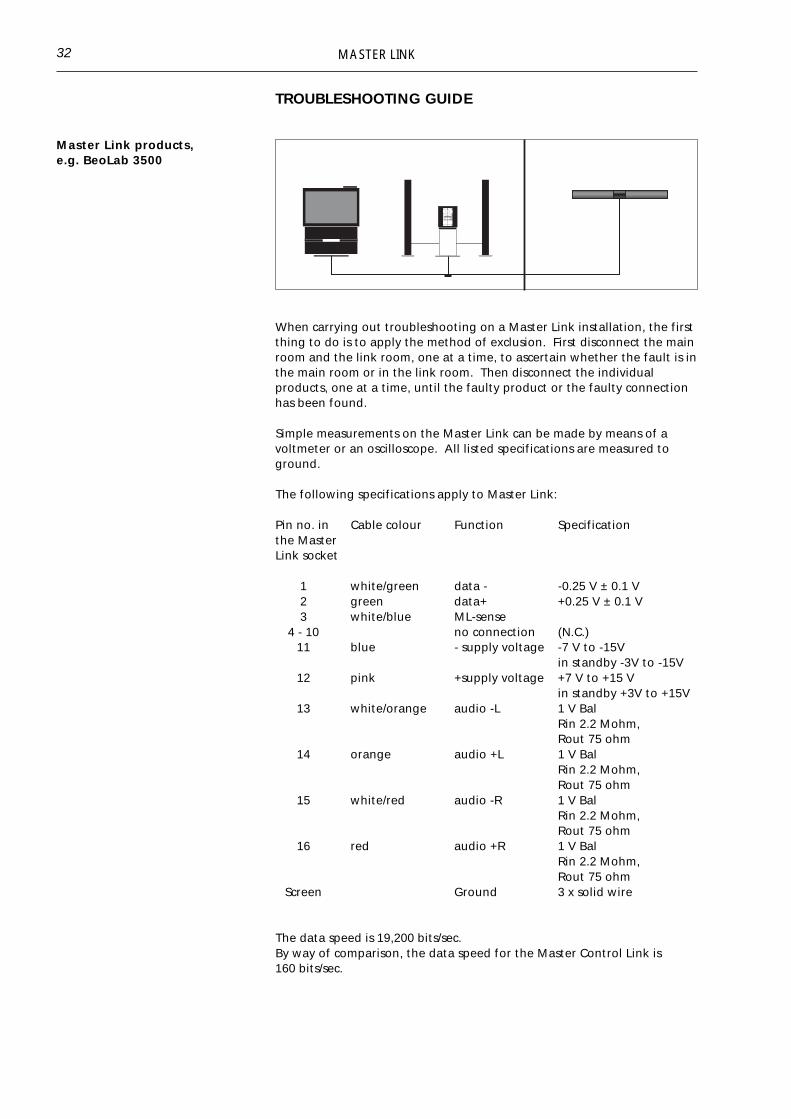
When carrying out troubleshooting on a Master Link installation, the firstthing to do is to apply the method of exclusion. First disconnect the mainroom and the link room, one at a time, to ascertain whether the fault is inthe main room or in the link room. Then disconnect the individualproducts, one at a time, until the faulty product or the faulty connectionhas been found.
Simple measurements on the Master Link can be made by means of avoltmeter or an oscilloscope. All listed specifications are measured toground.
The following specifications apply to Master Link:
Pin no. in Cable colour Function Specificationthe MasterLink socket
1 white/green data - -0.25 V ± 0.1 V2 green data+ +0.25 V ± 0.1 V3 white/blue ML-sense
4 - 10 no connection (N.C.)11 blue - supply voltage -7 V to -15V
in standby -3V to -15V12 pink +supply voltage +7 V to +15 V
in standby +3V to +15V13 white/orange audio -L 1 V Bal
Rin 2.2 Mohm,Rout 75 ohm
14 orange audio +L 1 V BalRin 2.2 Mohm,Rout 75 ohm
15 white/red audio -R 1 V BalRin 2.2 Mohm,Rout 75 ohm
16 red audio +R 1 V BalRin 2.2 Mohm,Rout 75 ohm
Screen Ground 3 x solid wire
The data speed is 19,200 bits/sec.By way of comparison, the data speed for the Master Control Link is160 bits/sec.
32

MASTER LINK
Possible causeThe product is connected to the mains and the stand-by diode is on.If the above is OK, do as follows:
- Meter data+ (pin 2) relative to ground- Meter data- (pin 1) relative to ground- Where no transmission, +/- 200 to 300 mV should be metered.- When data is being transmitted, 0V should be metered.
Measurement with oscilloscope.
Meter the following:
No transmission ———————————— + 0.25———————————— 0———————————— -0.25
Transmission
TroubleNo sound and no operation
If data- and data+ are not as shown at “No transmission” and are unableto transmit, the fault may be in the main room’s BeoVision or BeoSound,since it is one of these two units that supplies this voltage.
Please note that in setups with a BeoLink Converter it is always theMaster Link driver that supplies the voltage. If there are two Master Linkdrivers, one of them will, when connected, configure itself as being theone that supplies the data voltage.
The fault is found by applying the method of exclusion. If the fault is notin one of the Master Link drivers, there is another product that pulls datalow or high respectively. Alternatively there could be a cable fault or aconnection fault. Data errors can also be displayed in service mode; seethe section on service mode.
If data is OK, proceed with the measurement of the supply voltage whichshould be as stated under the specifications. If the voltage is not OK,apply the method of exclusion until the faulty product or the faultyconnection has been found.
33
No sound but operation OK The data and supply voltages are in this case OK. Meter the signal levelsat pins 13 to 16 in relation to the stated specifications. If the signal levelsare OK, the fault is in the link room product, perhaps in the converterbox, or it may be a faulty cable or connection.
Play only at half volume One of the balanced audio signals has dropped out.
MASTER LINK
Service mode Products with a display feature a service mode in which Master Link faultscan be displayed. Please note that the error reading indicates that thefault is a system fault, which does not mean that the fault is in theparticular product that is displaying it.
Beolab 3500 and BeoVision Avant are examples of products providing theservice mode feature. Check the service manual for the individualproducts to see how these procedures are accessed.
This example of service mode is from Beolab 3500.
ERROR 1: - Address configuration is impossible.
Error during address configuration. No address has been allocatedbecause too many units are connected to the Master Link.
- Remove all products from Master Link, and connect them again one ata time until the error code occurs. Disconnect that product from MasterLink.
ERROR 2: - Master Link data pulled low
It is not possible to transmit on Master Link, because it has been pulledlow. The error may occur if there is no Master Link driver circuit, or as aresult of a physical short-circuit on Master Link or in the data transceivercircuits.
- Disconnect one product from Master Link at a time, and see if it startsup.
- Reset the faulty product, and check the connection (cable/plug) andsignal path (the data transceiver circuit). See repair tips for the datatransceiver circuit.
ERROR 3: - Master Link data pulled high.
It is not possible to transmit on Master Link, because it has been pulledhigh. This error is caused either by the pull-up resistance in the systemhaving become too small or by an error in the data transceiver circuit.
- Disconnect one product from Master Link at a time, and see if it startsup.
- Reset the faulty product, check whether the Master Link cable is toolong, and check the signal path (the data transceiver circuit). See repairtips for the Master Link data transceiver circuit.
ERROR 4: - Data collision on Master Link
The data traffic on Master Link has been excessive, or a product hasjammed and will not receive data telegrams.
- Press the operating sequence again.- Disconnect one product from Master Link at a time to determine which
product has jammed. Reset the faulty product, and check the MasterLink connection (cable/plug) and signal path (amplifiers in the datatransceiver circuit).
See the service manual for the individual products for furtherinformation.
34
MASTER LINK 35
GLOSSARY
Audio Aux Link Perhaps better known as AV connection . Connection between the audioand video systems. The connection is established through a 7-pin datalinkcable.
21-pin AV cable / SCART Standard connection between a TV set and a video tape recorder. Thecable is specified for transferring RGB signals.
AV system Audio/video system. Integration of audio and video, permitting sound tobe transferred from one system to the other.
BeoLink The brand name and a general term describing Bang & Olufsen’s way ofdistributing sound and picture. BeoLink may be obtained in differentways depending on the products used: either the Audio Aux Link/MasterControl Link (MCL) system or the Master Link system.
Beomaster Designation of audio masters, e.g. Beomaster 7000 and Beocenter 9500.In future this designation will be replaced by BeoSound.
BeoSound Common designation of audio products, e.g. BeoSound Ouverture.
BeoVision
Compatibility
Common designation of TV sets, e.g. Beovision MX 6000 and BeoVisionAvant.
The ability to interconnect products from different seasons.
Control box A box that controls data and signals, for example in BeoLink Active.
Datalink cable 7-pin datalink cable used for Audio Aux Link connection between audioand video systems.
Link room kits Kits specially designed for link rooms, e.g. BeoLink Active and BeoLinkVideo.
Link room products Products specially designed for link rooms, e.g. Beolab 3500.
Main room products Products which serve as driver in a BeoLink system, e.g. BeoVision andBeoSound.
Link room Designation of the other room/rooms in the home in which sound and/orpicture are installed.
Main room Designation of the room in which the audio and/or video systems areplaced. There are two kinds of main rooms
ONE-room = audio and video systems placed in the same roomTWO-room = audio and video systems placed in separate rooms.

MASTER LINK36
Master Control Link (MCL) Master Control Link is the name of the former connection between mainroom and link room.
Master Link (ML) Bang & Olufsen’s new systems interface. Master Link is the connectionbetween the products in the main room and those in the link room but itis also the connection between the audio system and the video system.
Master Link driver BeoSound and BeoVision with Master Link socket. One of these productsis always required in a Master Link setup.
Master Link product All products with a Master Link socket.
One-way remote control A remote control terminal that operates the products by transmitting acommand to them without requiring an answer (e.g. BL 1000 and Beo4).
BL 5000 and BL 7000 are two-way remote control terminals which requirean answer from the product being operated.
Option programming Option programming is executed via a Bang & Olufsen terminal and withthe products concerned in stand-by.Upon completed option programming, the products “know” what kind ofenvironment they are placed in, and they can then be operated andfunction optimally.
Power Link (PL) The Power Link connection contains all necessary signals and datarequired for driving active speakers. Two different types of cable areavailable: one with wire for display data and one without wire for displaydata. Note that the latter cannot be used for active speakers with display.
Product Configuration Guide (PCG) A PC-based tool in which it is possible to compose the setup you want andwhich provides answers to any questions concerning compatibility, setups,options, terminals, special conditions, and much more.
Receiver IR receiver built into video, audio and link products. The products canthus be operated by means of a one-way remote control terminal, e.g.Beolink 1000 and Beo4.
MASTER LINK 37
Notes :

MASTER LINK38

MASTER LINK
ACCESSORIES
For information about other spare parts, see the "Accessories" handbook.
Master Link CableUsed for connection between twoproducts or between a wall socket anda product. Ø 6.5 mm
6270632 3.0 m with one plug, black
6270708 0.5 m with two plugs, black6270709 1.5 m with two plugs, black6270631 3.0 m with two plugs, black6270711 5.0 m with two plugs, black6270633 10.0 m with two plugs, black6270635 20.0 m with two plugs, black
Master Link Cable without plugsRunning metres of Master Link cable.Used for connection between wallsockets.Ø 6.5 mm
6250418 100 m, grey6250422 100 m, black6250423 100 m, white
Power Link cableSignal and control cable between twoPower Link sockets, with wire fordisplay data.Ø 3.5 mm
6270687 2.5 m, black6270688 5.0 m, black6270689 10.0 m, black6270696 20.0 m, black6250404 100 m, black, without plugs6250438 100 m, white, without plugs
Power Link cableSignal and control cable between twoPower Link sockets, without wire fordisplay data.Ø 2.5 mm
6270644 2.5 m, black6270645 5.0 m, black6270646 10.0 m, black6270647 20.0 m, black6250462 100 m, without plugs
39

MASTER LINK
Power Link T-branchUsed for serial connection of activespeakers.
6270706 0.3 m6270705 1.6 m
Datalink cableUsed for connection between twoproducts or between a wall socket anda product.
Black Grey Length6270222 6270393 1.5 m, two plugs6270639 6270640 3.0 m, two plugs6270353 6270394 5.0 m, two plugs6270337 6270395 10.0m, two plugs6270354 6270396 20.0m, two plugs6250265 6250269 100 m, without plugs6270338 1.5 m extension cord, black
Low capacitor receiver cableUsed for connection between IR-eyeand BeoLink Active/Passive, wheremore than 5 m of cable is required.
6270668 15 m, white
DIN plug, maleUsed with Power Link cables.
7220163 7-pin, black7220688 7-pin, grey7220701 7-pin, grey, angle7220573 8-pin, black7220345 8-pin, grey
40
AUX T-branchUsed for connection between BeoLinkConverter and one Audio and oneVideo product with Datalinkconnections.
6270702

MASTER LINK
7220026 Male, metal7211072 Female, metal
Cable cover, narrowLength: 2.5 m Colour: whiteInternal dimensions: 8 x 18 mmAvailable in cartons of 10 pieces each.2560257
2548255 Outside corner (1)2548256 Inside corner (2)2548257 L-shaped piece (3)7219071 Junction box (incl. special
terminal strip f. MCL) (4)2369117 Nail plugs (100 pieces) for
mounting of Cable covers.
Cable cover, roundFor concealing wiring from BeoLab3500 on the wall.Length: 2.5 mColour: whiteAvailable in cartons of 10 pieces each.
2560276
Cable cover, flexibleFlexible plastic tube.Internal diameter: 23 mmColour: whiteAvailable in coils of 10 m.
2952033
Wall socketWall socket with Master Link socket.Solder free terminals. Used for MasterLink connection, between rooms orbetween Master Link products andwall socket.
7210937 72 x 50 mm, grey (DK)7210938 72 x 50 mm, white (DK)7210940 80 x 80 mm, white
(EURO)
41
Coaxial plug

MASTER LINK
Wall socket, 8-pin DINWall socket with 8-pin DIN socket withsolder terminals.Used for plug connection betweenaudio system and wall socket.
7210675 49 x 49 x 24 mm, white(DK)
7210473 49 x 49 x 24 mm, grey(DK)
7210512 80 x 80 x 24 mm, white(EURO)
Fixture boxDK fixture box for wall socket. Usedfor flush mounting in brick orplasterboard walls.
Dimensions: 80 x 83 mm
7219089
Mounting baseDK mounting base for wall socket.Used for mounting on the outside ofe.g. a brick wall.
Dimensions: 80 x 53 x 30 mm
7210898 grey7210899 white
Surface mounting baseMounting base for wall socket.Used for mounting on the outside ofe.g. a brick wall.
7210681 For 49 x 49 mm wallsocket, white (DK)
7210474 For 49 x 49 mm wallsocket, grey (DK)
7219092 For 80 x 80 mm wallsocket, white (EURO)
Fixture boxFixture box for wall sockets.Used for flush-mounting in brick wallsor plasterboard walls.
7219048 52 x 52 x 37 mm (DK)7219090 71 x 71 x 44 mm (EURO)
42

MASTER LINK
Blanking platePlate for covering installations not inuse.
3164593 49 x 49 x 24 mm, grey(DK)
3164707 49 x 49 x 24 mm, white(DK)
Outdoor mounting boxOutdoor mounting box for ML andMCL transceiver.
Dimensions: 75 x 125 x 175 mm
3132221
Build-in kit for ML transceiver,solid wall
Used for invisible installations in solidwalls.
3375187
Build-in kit for ML transceiver,light partition wall
Used for invisible installations in lightpartition walls.
3375188
ML socketMaster Link socket for mounting inoptional wall plate (blanking cover).
8009947
43

MASTER LINK
ML junction box, smallUsed for length-adjustment of MLcable, colour-change of cable and forconnections between products.
3132170 black3132197 grey3132220 white
ML junction box, largeUsed for Master Link connectionsbetween products.
3375189 black
ToolsProfessional tools for terminating.
3629127 For terminating in ML wallsocket
3629132 For terminating in MLjunction box.
44

MASTER LINK
Notes :
45

MASTER LINK
Notes :
46

MASTER LINK

BANG & OLUFSENDK - 7600 STRUERDENMARK
TELEPHONE 96841122*CABLE ADDRESS BANGOLUFTELEFAX 97853911
3540230 04-97 B
PRIN
TED
IN D
ENM
AR
K B
Y B
OG
TRY
KK
ERG
ÅR
DEN
AS,
STR
UER