Embed Size (px)
Citation preview
Chapter 25 Master Minimum Equipment List (MMEL) 569
Chapter 25
Master Minimum Equipment List (MMEL)
About RAM Commander’s MMEL Module The Master Minimum Equipment List (MMEL) is a document which lists the equipment that may temporarily be inoperative, subject to certain conditions, whilst maintaining an acceptable level of safety as intended in the applicable documents. Each MMEL is specific to an aircraft type.
RAM Commander’s MMEL module main features: 1. Compliance with MMEL requirements
2. Interconnectivity with aircraft Reliability and Safety analyses
3. Candidate Item selection
4. Calculation(s) of Expected Probability before and after failure
5. Automatic identification of the next (first in flight) and second worst failures
Reports generation:
• Standard MMEL : “Five Column Format” – presents the standard MMEL report
• Detailed Quantitative Analysis – presents results of analysis on which MMEL selection has been made
570 RAM Commander User’s Guide
Prerequisites for MMEL generation using RAM Commander MMEL Module
In order to generate an adequate MMEL you need to perform Reliability/FMECA and Safety analyses prior to initiating the MMEL Module. Performance of MMEL quantitative analysis utilizes the following information which is the results of Reliability/FMECA and Safety analyses:
RAM Commander fields Item Data: 1. Item Name (Ref.Des.)
2. Item ATA Number
3. Item operating Failure Rate
RAM Commander Project Data: 1. FHA – Functional Hazard Analysis
2. FMECA – Failure Mode End Effect Criticality Analysis
3. FTA – Fault Tree Analysis
Additional requirement is the connection between following types of analyses:
FMECA with FTA: 1. Failure modes defined in the FMECA must be used as Basic
Events in FTA.
2. Each Basic Event must be connected to a corresponding Failure Mode through Product Tree ID and Failure Mode Number.
FHA with FTA: Each Fault Tree in FTA must be connected to a corresponding Failure Condition in FHA. This connection is established done at the Safety Assessment Definition screen.
Chapter 25 Master Minimum Equipment List (MMEL) 571
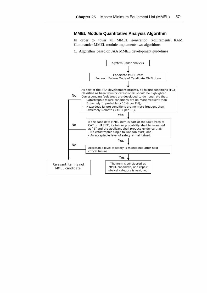
MMEL Module Quantitative Analysis Algorithm In order to cover all MMEL generation requirements RAM Commander MMEL module implements two algorithms:
1. Algorithm based on JAA MMEL development guidelines
System under analysis
As part of the SSA development process, all failure conditions (FC) classified as hazardous or catastrophic should be highlighted. Corresponding fault trees are developed to demonstrate that: - Catastrophic failure conditions are no more frequent than
Extremely Improbable (<10-9 per FH); - Hazardous failure conditions are no more frequent than
Extremely Remote (<10-7 per FH).
No
Yes
No
Candidate MMEL item For each Failure Mode of Candidate MMEL item
Acceptable level of safety is maintained after next critical failure
The item is considered as MMEL candidate, and repair
interval category is assigned.
Yes
Yes
No
If the candidate MMEL item is part of the fault trees of CAT or HAZ FC, its failure probability shall be assumed as “1” and the applicant shall produce evidence that: - No catastrophic single failure can exist, and - An acceptable level of safety is maintained.
Relevant item is not MMEL candidate.
572 RAM Commander User’s Guide
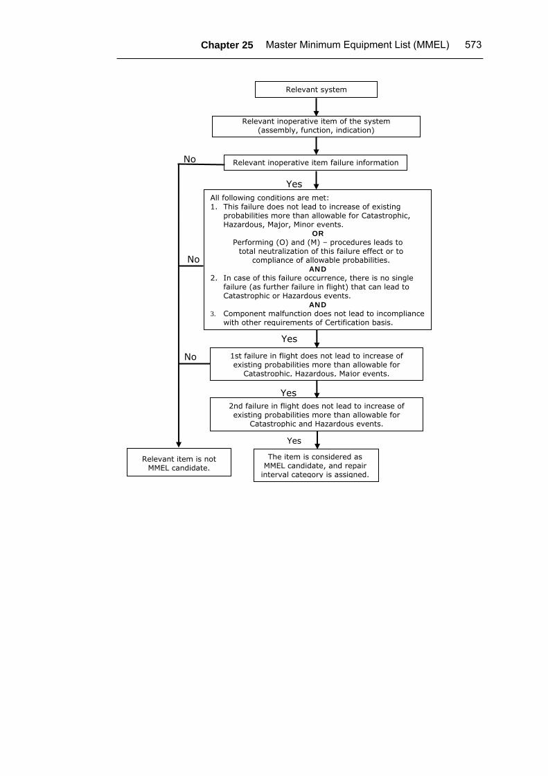
2. Algorithm implementing RRJ – 95/75 guidelines - Decision making algorithm for inclusion of assemblies (equipment) in MMEL.
Chapter 25 Master Minimum Equipment List (MMEL) 573
Relevant system
Relevant inoperative item failure information
Relevant item is not MMEL candidate.
No
Yes
No
Relevant inoperative item of the system (assembly, function, indication)
1st failure in flight does not lead to increase of existing probabilities more than allowable for
Catastrophic, Hazardous, Major events.
The item is considered as MMEL candidate, and repair
interval category is assigned.
Yes
Yes
No
All following conditions are met: 1. This failure does not lead to increase of existing
probabilities more than allowable for Catastrophic, Hazardous, Major, Minor events.
OR Performing (О) and (М) – procedures leads to
total neutralization of this failure effect or to compliance of allowable probabilities.
AND 2. In case of this failure occurrence, there is no single
failure (as further failure in flight) that can lead to Catastrophic or Hazardous events.
AND 3. Component malfunction does not lead to incompliance
with other requirements of Certification basis.
2nd failure in flight does not lead to increase of existing probabilities more than allowable for
Catastrophic and Hazardous events.
Yes
574 RAM Commander User’s Guide
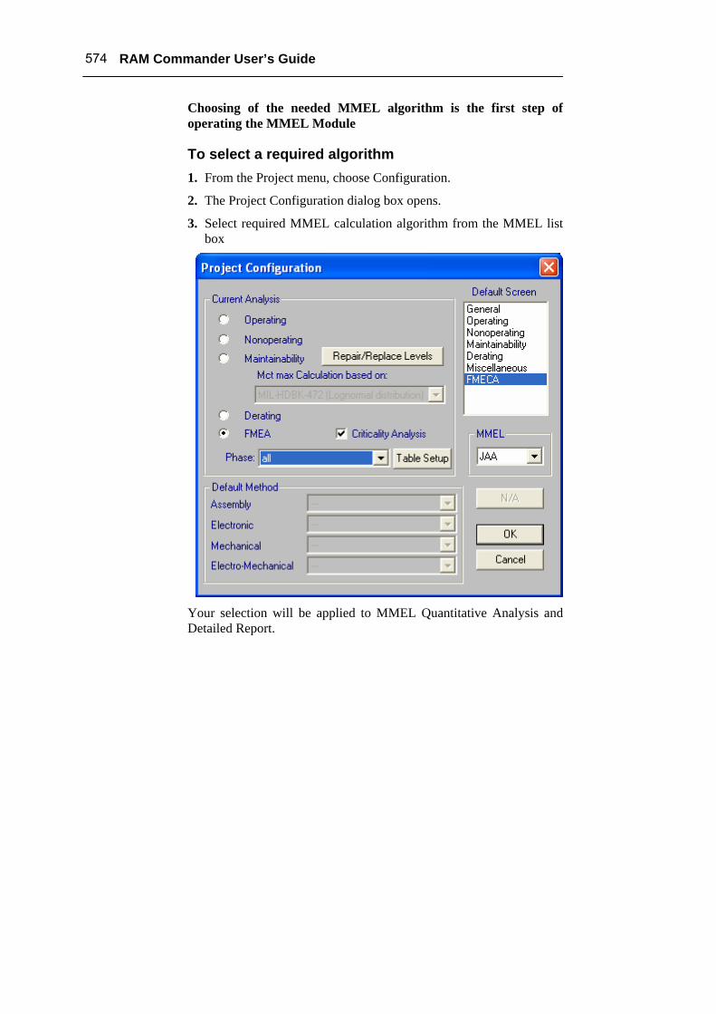
Choosing of the needed MMEL algorithm is the first step of operating the MMEL Module
To select a required algorithm 1. From the Project menu, choose Configuration.
2. The Project Configuration dialog box opens.
3. Select required MMEL calculation algorithm from the MMEL list box
Your selection will be applied to MMEL Quantitative Analysis and Detailed Report.
Chapter 25 Master Minimum Equipment List (MMEL) 575
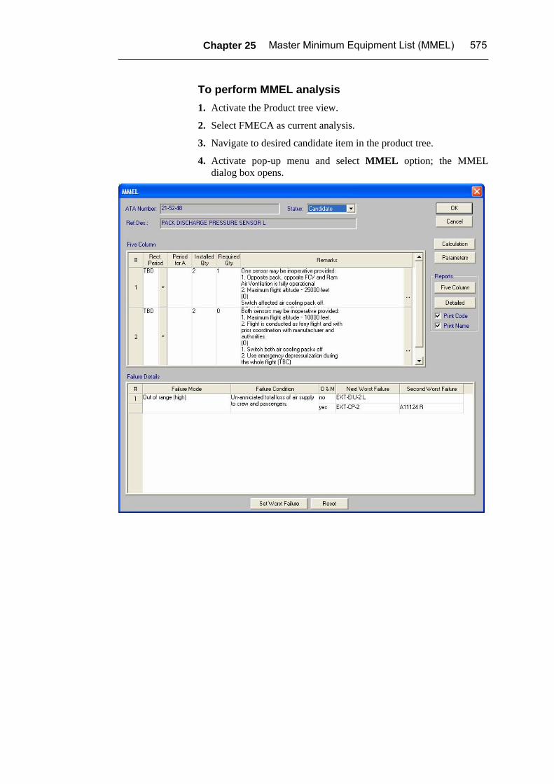
To perform MMEL analysis 1. Activate the Product tree view.
2. Select FMECA as current analysis.
3. Navigate to desired candidate item in the product tree.
4. Activate pop-up menu and select MMEL option; the MMEL dialog box opens.
576 RAM Commander User’s Guide
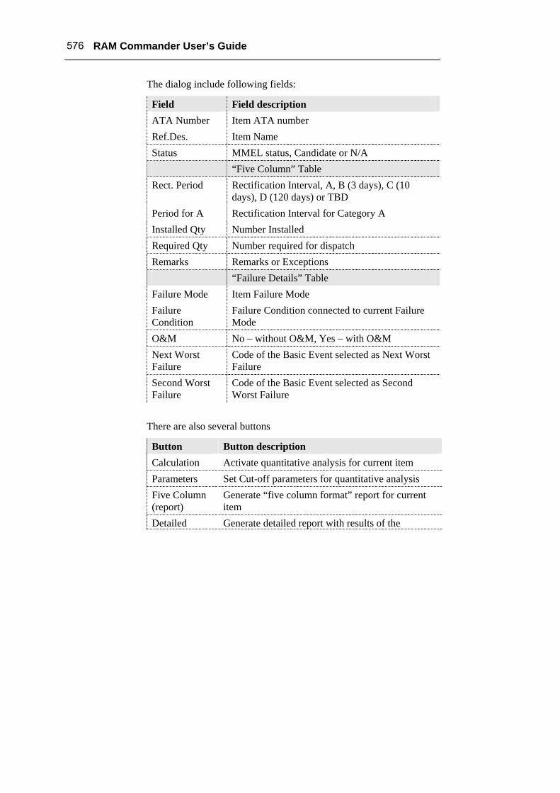
The dialog include following fields:
Field Field description ATA Number Item ATA number Ref.Des. Item Name Status MMEL status, Candidate or N/A “Five Column” Table Rect. Period Rectification Interval, A, B (3 days), C (10
days), D (120 days) or TBD Period for A Rectification Interval for Category A Installed Qty Number Installed Required Qty Number required for dispatch Remarks Remarks or Exceptions “Failure Details” Table Failure Mode Item Failure Mode Failure Condition
Failure Condition connected to current Failure Mode
O&M No – without O&M, Yes – with O&M Next Worst Failure
Code of the Basic Event selected as Next Worst Failure
Second Worst Failure
Code of the Basic Event selected as Second Worst Failure
There are also several buttons
Button Button description Calculation Activate quantitative analysis for current item Parameters Set Cut-off parameters for quantitative analysis Five Column (report)
Generate “five column format” report for current item
Detailed Generate detailed report with results of the
Chapter 25 Master Minimum Equipment List (MMEL) 577
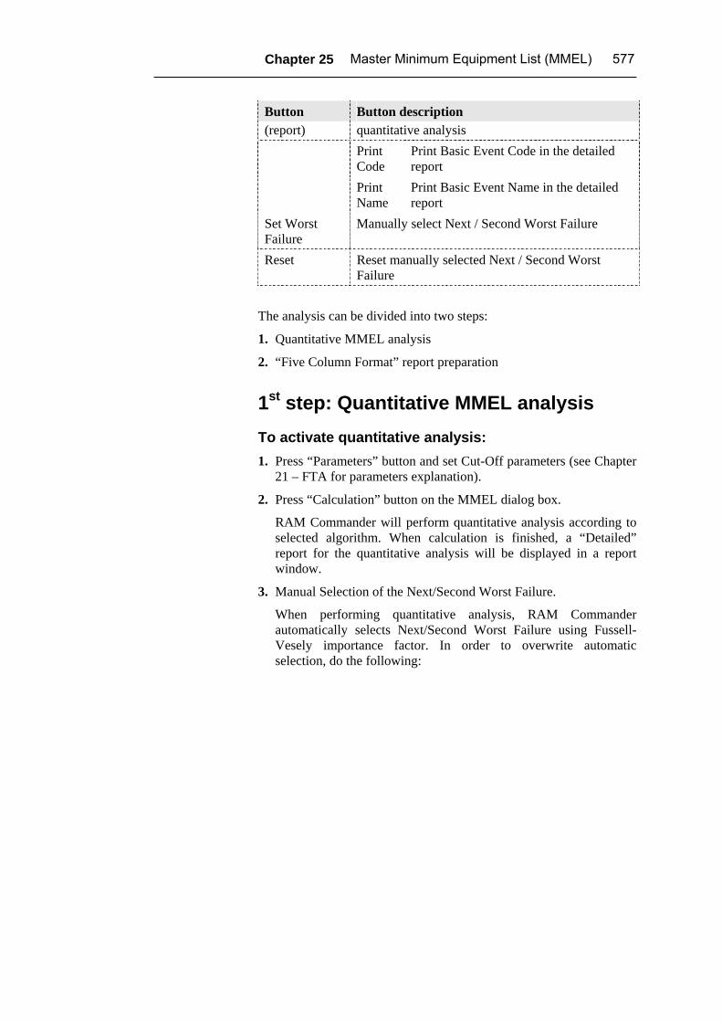
Button Button description (report) quantitative analysis Print
Code Print Basic Event Code in the detailed report
Print Name
Print Basic Event Name in the detailed report
Set Worst Failure
Manually select Next / Second Worst Failure
Reset Reset manually selected Next / Second Worst Failure
The analysis can be divided into two steps:
1. Quantitative MMEL analysis
2. “Five Column Format” report preparation
1st step: Quantitative MMEL analysis To activate quantitative analysis: 1. Press “Parameters” button and set Cut-Off parameters (see Chapter
21 – FTA for parameters explanation).
2. Press “Calculation” button on the MMEL dialog box.
RAM Commander will perform quantitative analysis according to selected algorithm. When calculation is finished, a “Detailed” report for the quantitative analysis will be displayed in a report window.
3. Manual Selection of the Next/Second Worst Failure.
When performing quantitative analysis, RAM Commander automatically selects Next/Second Worst Failure using Fussell-Vesely importance factor. In order to overwrite automatic selection, do the following:
578 RAM Commander User’s Guide
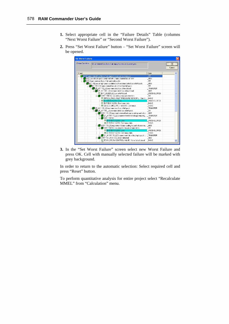
1. Select appropriate cell in the “Failure Details” Table (columns “Next Worst Failure” or “Second Worst Failure”).
2. Press “Set Worst Failure” button – “Set Worst Failure” screen will be opened.
3. In the “Set Worst Failure” screen select new Worst Failure and
press OK. Cell with manually selected failure will be marked with grey background.
In order to return to the automatic selection: Select required cell and press “Reset” button.
To perform quantitative analysis for entire project select “Recalculate MMEL” from “Calculation” menu.
Chapter 25 Master Minimum Equipment List (MMEL) 579
2nd step: “Five Column Format” Report Preparation
Note: This step is performed only if after the quantitative analysis it has been decided that an Item is considered as a MMEL candidate.
Prior to generation of "Five Column Format" Report you have to do the following: 1. Set Item MMEL status to “Candidate”
2. Select Rect. Period from the list
3. Enter rectification interval for category A, if such category selected
4. Enter number (quantity) of items normally installed in the aircraft
5. Enter minimum number (quantity) of items required for operation
6. Enter Remarks or Exceptions
To generate “Five Column Format” report 1. Press MMEL button.
To view “Detailed Quantitative Analysis” report 1. Press the Detailed button.
Note: The view is available only if a quantitative analysis has been already performed.
To generate a complete "Five Column Format" list repeat the actions for each Candidate Item.
580 RAM Commander User’s Guide
MMEL Module Reports To create MMEL reports 1. Activate the Product tree view.
2. Select FMECA as current analysis
3. Navigate to a desired level in the Product Tree.
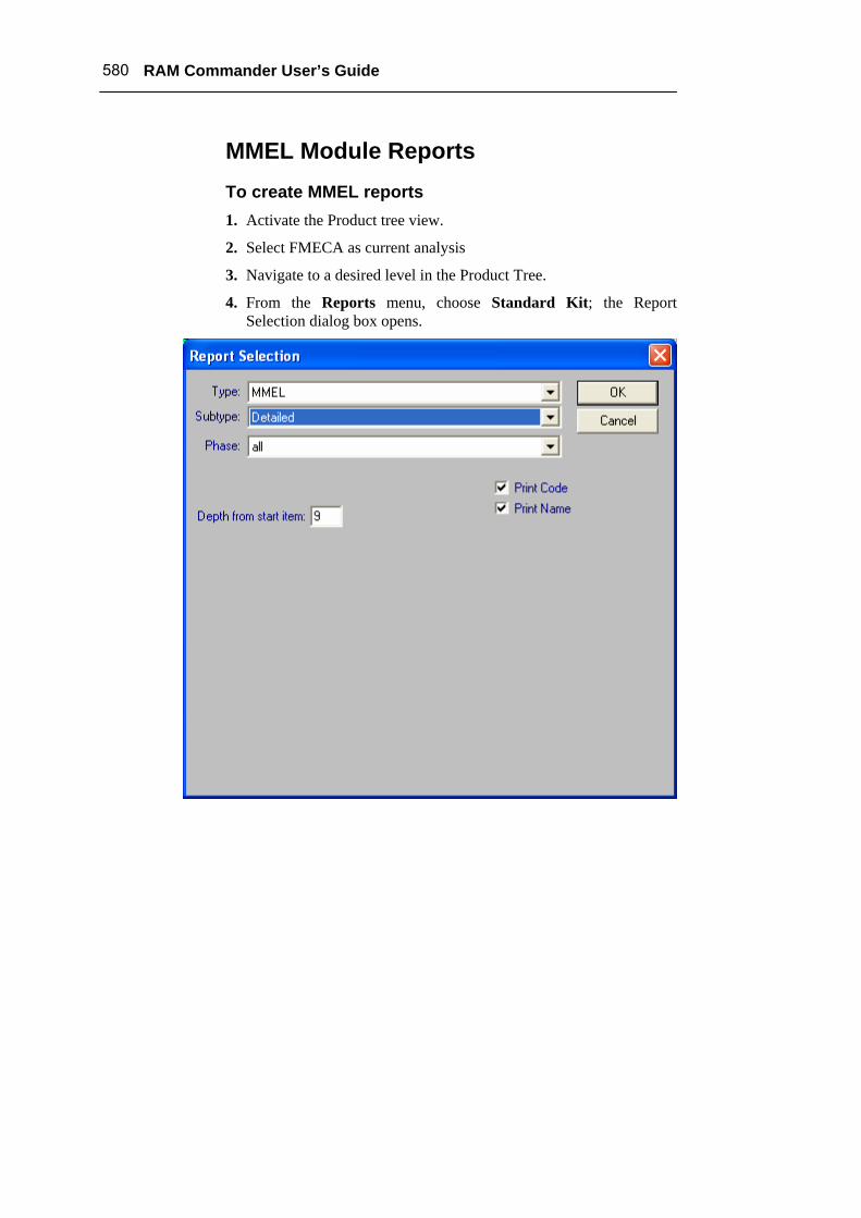
4. From the Reports menu, choose Standard Kit; the Report Selection dialog box opens.
Chapter 25 Master Minimum Equipment List (MMEL) 581
5. Select the report Type: “MMEL”.
6. Select the report Subtype: “Candidate List”, “Five Column” or “Detailed”.
7. Choose OK.
RAM Commander generates and displays the report in a report window. Only items with the MMEL status equal to “Candidate” will be included in the report.
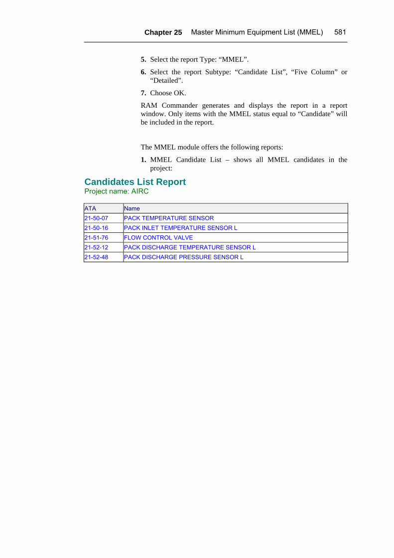
The MMEL module offers the following reports:
1. MMEL Candidate List – shows all MMEL candidates in the project:
Candidates List Report Project name: AIRC
ATA Name 21-50-07 PACK TEMPERATURE SENSOR 21-50-16 PACK INLET TEMPERATURE SENSOR L 21-51-76 FLOW CONTROL VALVE 21-52-12 PACK DISCHARGE TEMPERATURE SENSOR L 21-52-48 PACK DISCHARGE PRESSURE SENSOR L
582 RAM Commander User’s Guide
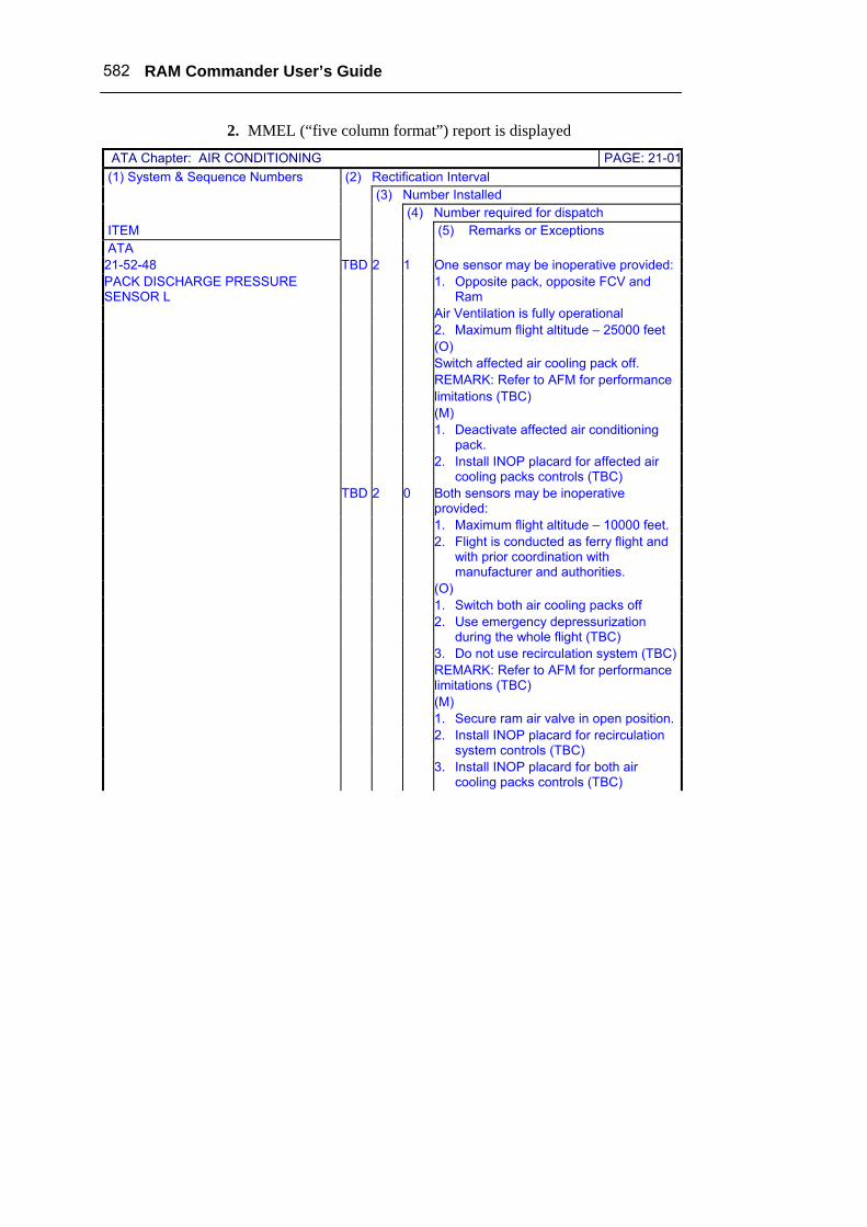
2. MMEL (“five column format”) report is displayed
ATA Chapter: AIR CONDITIONING PAGE: 21-01 (1) System & Sequence Numbers (2) Rectification Interval (3) Number Installed (4) Number required for dispatch ITEM (5) Remarks or Exceptions ATA 21-52-48 TBD 2 1 One sensor may be inoperative provided: PACK DISCHARGE PRESSURE SENSOR L
1. Opposite pack, opposite FCV and Ram
Air Ventilation is fully operational 2. Maximum flight altitude – 25000 feet (О) Switch affected air cooling pack off. REMARK: Refer to AFM for performance limitations (TBC) (М) 1. Deactivate affected air conditioning
pack. 2. Install INOP placard for affected air
cooling packs controls (TBC) TBD 2 0 Both sensors may be inoperative
provided: 1. Maximum flight altitude – 10000 feet. 2. Flight is conducted as ferry flight and
with prior coordination with manufacturer and authorities.
(О) 1. Switch both air cooling packs off 2. Use emergency depressurization
during the whole flight (TBC) 3. Do not use recirculation system (TBC) REMARK: Refer to AFM for performance
limitations (TBC) (М) 1. Secure ram air valve in open position. 2. Install INOP placard for recirculation
system controls (TBC) 3. Install INOP placard for both air
cooling packs controls (TBC)
Chapter 25 Master Minimum Equipment List (MMEL) 583
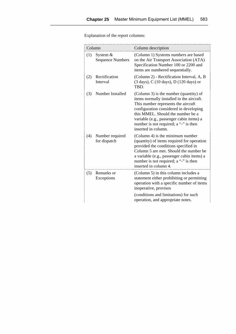
Explanation of the report columns:
Column Column description (1) System &
Sequence Numbers (Column 1) Systems numbers are based on the Air Transport Association (ATA) Specification Number 100 or 2200 and items are numbered sequentially.
(2) Rectification Interval
(Column 2) - Rectification Interval, A, B (3 days), C (10 days), D (120 days) or TBD.
(3) Number Installed (Column 3) is the number (quantity) of items normally installed in the aircraft. This number represents the aircraft configuration considered in developing this MMEL. Should the number be a variable (e.g., passenger cabin items) a number is not required; a “-” is then inserted in column.
(4) Number required for dispatch
(Column 4) is the minimum number (quantity) of items required for operation provided the conditions specified in Column 5 are met. Should the number be a variable (e.g., passenger cabin items) a number is not required; a “-” is then inserted in column 4.
(5) Remarks or Exceptions
(Column 5) in this column includes a statement either prohibiting or permitting operation with a specific number of items inoperative, provisos (conditions and limitations) for such operation, and appropriate notes.
584 RAM Commander User’s Guide
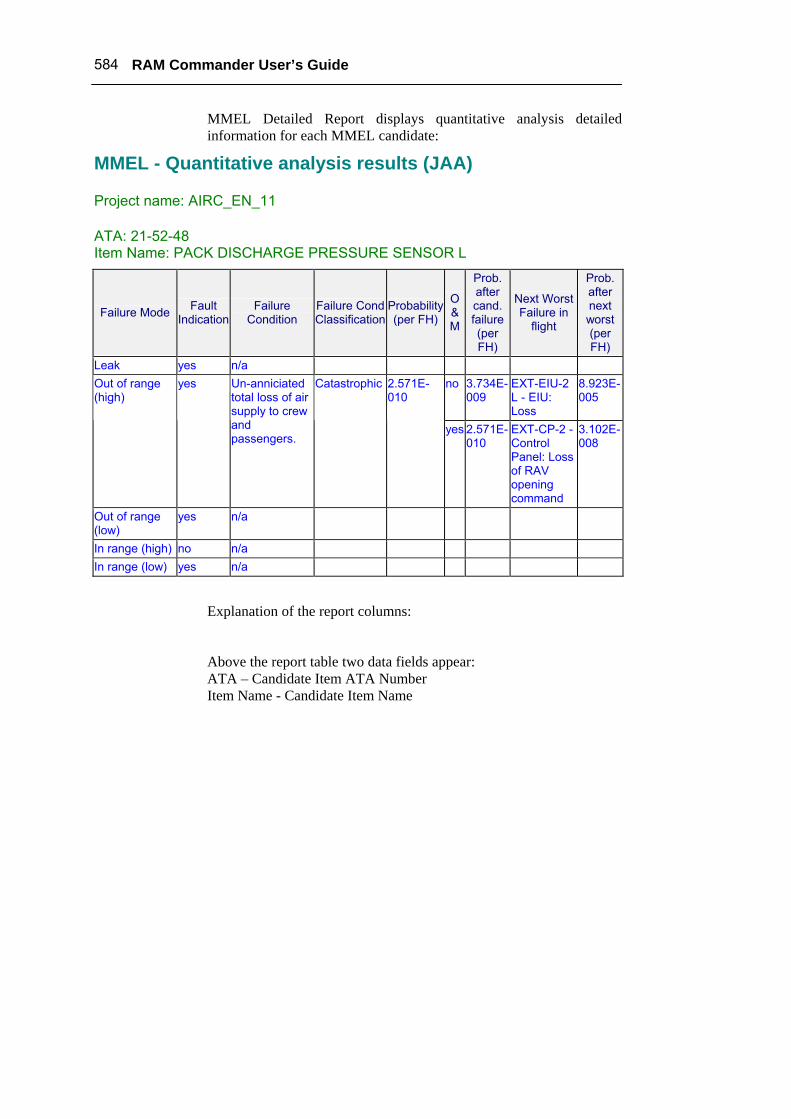
MMEL Detailed Report displays quantitative analysis detailed information for each MMEL candidate:
MMEL - Quantitative analysis results (JAA) Project name: AIRC_EN_11 ATA: 21-52-48 Item Name: PACK DISCHARGE PRESSURE SENSOR L
Failure Mode Fault Indication
Failure Condition
Failure CondClassification
Probability (per FH)
O & M
Prob. after cand. failure (per FH)
Next Worst Failure in
flight
Prob. after next worst (per FH)
Leak yes n/a no 3.734E-
009 EXT-EIU-2 L - EIU: Loss
8.923E-005
Out of range (high)
yes Un-anniciated total loss of air supply to crew and passengers.
Catastrophic 2.571E-010
yes 2.571E-010
EXT-CP-2 - Control Panel: Loss of RAV opening command
3.102E-008
Out of range (low)
yes n/a
In range (high) no n/a In range (low) yes n/a
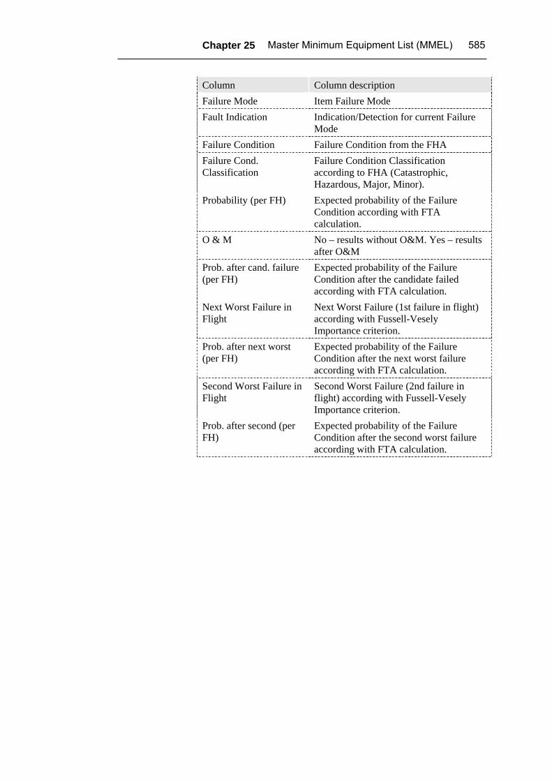
Explanation of the report columns:
Above the report table two data fields appear: ATA – Candidate Item ATA Number Item Name - Candidate Item Name
Chapter 25 Master Minimum Equipment List (MMEL) 585
Column Column description Failure Mode Item Failure Mode Fault Indication Indication/Detection for current Failure
Mode Failure Condition Failure Condition from the FHA Failure Cond. Classification
Failure Condition Classification according to FHA (Catastrophic, Hazardous, Major, Minor).
Probability (per FH) Expected probability of the Failure Condition according with FTA calculation.
O & M No – results without O&M. Yes – results after O&M
Prob. after cand. failure (per FH)
Expected probability of the Failure Condition after the candidate failed according with FTA calculation.
Next Worst Failure in Flight
Next Worst Failure (1st failure in flight) according with Fussell-Vesely Importance criterion.
Prob. after next worst (per FH)
Expected probability of the Failure Condition after the next worst failure according with FTA calculation.
Second Worst Failure in Flight
Second Worst Failure (2nd failure in flight) according with Fussell-Vesely Importance criterion.
Prob. after second (per FH)
Expected probability of the Failure Condition after the second worst failure according with FTA calculation.
586 RAM Commander User’s Guide
Summary In this section, you learned about RAM Commander’s Master Minimum Equipment List (MMEL) module. Using this module, you can perform quantitative MMEL analysis and generate standard “five column format” report.
See more about relevant to MMEL RAM Commander modules: FMECA in Chapter 18 and FTA in Chapter 21.