Embed Size (px)
Citation preview

Structures
Master Specification
ST-SC-C7 Placement of Concrete Document Information
K Net Number: 13434810
Document Version: 3
Document Date: August 2021

Structures Contents
Master Specification 2
Document Amendment Record
Version Change Description Date
1 Initial issue (formerly CC25) 28/06/19
2 Formatting for publishing 19/09/19
3 Clause 3.7, 5.1, 5.2, 6.1, 6.2 amended August 2021
Document Management This document is the Property of the Department for Infrastructure and Transport and contains information that is confidential to the Department. It must not be copied or reproduced in any way without the written consent of the Department. This is a controlled document and it will be updated and reissued as approved changes are made.
Structures Contents
Master Specification 3
Contents Contents 3
ST-SC-C7 Placement of Concrete 4
1 General 4
2 Quality Requirements 4
3 Concrete Placement 4
4 Finishing of Uniformed Concrete Surfaces 5
5 Curing 6
6 Cracking of Concrete 7
7 Surface Finish 8
8 Tolerances 8
9 Hold Points 11
Structures ST-SC-C7 Placement of Concrete
Master Specification 4
ST-SC-C7 Placement of Concrete
1 General
1.1 This Part specifies the requirements for the placement, curing and stripping of concrete and the properties of the finished product.
1.2 Documents referenced in this Part are listed below:
a) AS 1379 The Specification and Manufacture of Concrete.
b) AS 1478.1 Admixtures for Concrete.
c) AS 2758.1 Concrete Aggregates.
d) AS 3610 Formwork for Concrete.
e) AS 3600 Concrete Structures.
f) AS 3799 Liquid Membrane - Forming Curing Compounds for Concrete.
g) AS 3972 Portland and Blended Cements.
h) HB64 Guide to Concrete Construction (joint publication of the Cement and Concrete Association of Australia and Standards Australia.
i) Vicroads Standard Specification 687 Repair of Concrete Cracks and 689 Cementitious Patch Repair of Concrete, available from http://webapps.vicroads.vic.gov.au/VRNE/csdspeci.nsf/.
j) DIT Road Structures Inspection Manual, Appendix D Bridge Repair Manual
2 Quality Requirements
2.1 At a minimum, the Contractor’s Quality Plan shall include the following documents, procedures and instructions:
a) procedures describing the proposed method of placing, compacting, finishing and curing the concrete, including the rate of placement, the number of personnel required and their responsibilities and required competencies, and the plant and equipment to be used, including required standby equipment;
b) procedures for set out and level control for bridge deck pours (where applicable);
c) procedures describing the measures that will be taken to protect freshly placed concrete and prevent evaporative moisture loss during finishing operations of concrete slabs;
d) details of the materials and measures to ensure compliance with the specified curing requirements;
e) the type of curing compound; and
f) procedures for precast abutment panel construction and installation (where applicable).
2.2 If not provided beforehand, the documentation shall be submitted at least 28 days prior to the commencement of site work.
2.3 Provision of the procedures and documentation listed in this Clause shall constitute a Hold Point.
3 Concrete Placement
General
3.1 Prior to placing concrete, a Hold Point shall apply. At least 24 hours’ notice shall be provided prior to placing concrete. If not previously provided, the Contractor shall submit evidence verifying that the reinforcement has been placed within the specified cover and tolerances (refer ST-SC-S6 “Steel Reinforcement”, Clause 3.6 “Cover and Tolerance”).

Structures ST-SC-C7 Placement of Concrete
Master Specification 5
3.2 Except where amended or added to by this Contract, concrete shall be transported, handled, placed, compacted, finished and cured in accordance with AS 3600, using the recommended processes described in HB64. Hand mixing is not permitted.
Stand-By Mixing Plant
3.3 The Contractor shall ensure that alternative supplies of concrete from stand-by mixing plant(s) can be made available immediately in the event of breakdown.
Traceability of Concrete
3.4 All concrete batches (truckloads) used in the works shall be traceable from the batch plant to its general location in the structure by a unique identification number.
Temperature at Time of Delivery
3.5 Concrete when delivered at the acceptance point shall have a temperature not less than 5°C nor greater than 35°C (refer AS 1379, Clause 4.4.2).
Construction Joints
3.6 All mandatory joints are shown on the drawings. Any proposal for additional planned joints shall constitute a Hold Point. All construction joints, including those with keys or dowels, shall be roughened to expose aggregate to provide a bond between the new and old concrete.
3.7 All construction joints, including those with keys or dowels, shall be:
a) roughened to expose coarse aggregate to provide a bond between the new and old concrete. Ensure reinforcement is not hit if mechanical roughening tools are used.
b) washed clean with water
c) all excess water and loose material shall be removed prior to placing the adjoining concrete.
Environmental Conditions for Placing Concrete
Requirements for Temperature and Other Adverse Conditions
3.8 Concrete shall not be placed if the air temperature at the site is below 5°C or the shade temperature at the site is over 35°C. Concreting in the open shall not be carried out during adverse conditions, such as rain, wind, dust or bushfires.
Additional Requirements for Elements with high Area to Volume Ratios
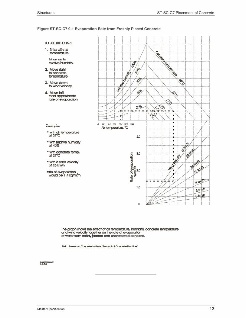
3.9 Concrete shall not be placed in decks, approach slabs and like elements with an area to volume ratio greater than or equal to 5 unless the rate of evaporation determined in accordance with Figure ST-SC-C7 9-1 Evaporation Rate from Freshly Placed Concrete is less than 1 kg/square metre/hour. In addition, concrete shall not be placed when the rate of evaporation is between 0.5 kg/square metre/hour and 1 kg/square metre/hour unless precautionary measures are taken to ensure the concrete can be placed and finished without defects.
Self-Compacting Concrete
3.10 Self-Compacting Concrete (SCC) shall not be vibrated. The concrete shall not be subjected to any physical disturbance after deposition.
4 Finishing of Uniformed Concrete Surfaces
General
4.1 Finish on unformed concrete surfaces are classified as follows:
a) Finish U1 - Screeded Finish.
Structures ST-SC-C7 Placement of Concrete
Master Specification 6
b) Finish U2 - Wood Floated Finish.
c) Finish U3 - Steel Floated Finish.
Finish U1 - Screeded Finish
4.2 A screeded finish will be applied to bridge decks and other surfaces that will be later covered with a bituminous wearing surface or to walkways and other surfaces required to take pedestrian traffic. The surface will be screeded, wood floated and then roughened by broom when the concrete has set sufficiently, to produce regular marks approximately 3 mm deep.
Finish U2 - Wood Floated Finish
4.3 A wood floated finish shall be applied to all surfaces that are not required to have either a U1 or U3 finish.
Finish U3 - Steel Floated Finish
4.4 Unless otherwise specified, a steel floated finish shall be applied to prominently exposed surfaces such as tops of wing walls, parapets, end walls, kerbs and the like. The steel floated finish shall provide a smooth uniform surface, true to line and level and free of marks.
5 Curing
5.1 Concrete in exposure classifications A, B1 and B2 must be continuously cured for 7 days when the concrete contains cement Types GP or SR complying with AS 3972 without mineral additions to the concrete mix, except that decks, footways, approach slabs and like elements with an area to volume ratio greater than or equal to 5 must be cured for 14 days.
5.2 Concrete in exposure classifications C1 or C2 shall be continuously cured for 14 days.
5.3 Where cement Types GB, LH or SL are a component of the concrete the curing times given here must be increased by 48 hours.
5.4 Curing of concrete must be by one of the following methods:
a) Water curing. All surfaces of the concrete must be kept moist for the specified periods of curing by continuous spraying, ponding, wet hessian, felt matting or sand blankets. Wet curing materials used on vertical surfaces must be effectively wrapped during the whole curing period.
b) Curing compounds. All curing compounds must comply with AS 3799. Curing compounds must not be applied to the upper surface of bridge decks unless approved otherwise. PVA based curing compounds are not permitted.
i) Such compounds must be pigmented sufficiently to allow visual inspection to ensure full application on the surface. The pigment must not be visible fourteen days after application. Curing compounds must not have a deleterious effect on the concrete or stain the surface of the concrete.
ii) The curing compound must be applied by a pressurised sprayer to give a uniform cover. The sprayer must incorporate a device for continuous agitation and mixing of the compound in its container during spraying. The curing compound must be applied using a fine spray at the rate stated on the certificate of compliance, or at a rate of 0.2 litres/m2 per coat, whichever is the greater. The application rate must be checked by calculating the amount of curing compound falling on felt mats, each approximately 0.25 m2 in area, placed on the concrete surface.
iii) Two coats must be applied at the full rate. The time between the first and second coat must be in accordance with the manufacturer's recommendation, or on the basis of a trial application.
iv) Curing compounds must not be applied to construction joints unless the joint is to be roughened or sandblasted at a later date.
v) Curing compounds must not be applied to surfaces which are to be subsequently coated unless they are compatible with the coating, waterproofing or surfacing system or provision
Structures ST-SC-C7 Placement of Concrete
Master Specification 7
is made for removal of the compound from these surfaces prior to the application of the coating, waterproofing or surfacing system.
c) Polyethylene sheet. Polyethylene sheet must be of sufficient strength to withstand wind and any imposed foot traffic or physical loading. Torn or punctured sheeting must not be used. Laps must be 300 mm minimum and edges and laps must be sealed by tape or held down by boards or other means. All edges and laps must be sealed against evaporative moisture losses for the duration of curing. Water must be sprayed under the sheeting at the edges and at laps on the day after placing concrete and at regular intervals to maintain moist conditions. Polyethylene sheet must not be used on concrete decks or slabs unless used in conjunction with water curing.
d) Curing membranes and curing compounds must be maintained intact for not less than the specified period of curing. Any damage to the curing membranes during the period of curing must be repaired immediately at the original rate of application.
e) Maintaining formwork. The formwork must be sealed against evaporative moisture losses for the duration of curing. Where formwork is removed prior to the completion of the curing period, curing must recommence within 30 minutes and continue until the total curing time is not less than the periods of curing specified in 5.1
f) Low pressure steam curing (for precast elements only. Refer to ST-SC-S4 "Low Pressure Steam Curing of Precast Units")
g) Heat accelerated curing (for precast elements only. Refer to ST-SC-S5 "Heat Accelerated Curing")
h) For steam cured and hot water cured precast units, curing times are able to be reduced in accordance with ST-SC-S4 "Low Pressure Steam Curing of Precast Units" or ST-SC-S5 "Heat Accelerated Curing" as appropriate. In these cases, curing is considered complete at the end of the curing cycle.
6 Cracking of Concrete
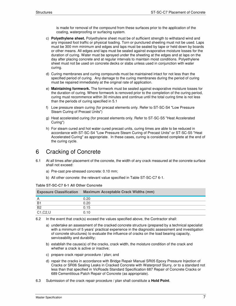
6.1 At all times after placement of the concrete, the width of any crack measured at the concrete surface shall not exceed:
a) Pre-cast pre-stressed concrete: 0.10 mm;
b) All other concrete: the relevant value specified in Table ST-SC-C7 6-1.
Table ST-SC-C7 6-1 All Other Concrete
Exposure Classification Maximum Acceptable Crack Widths (mm)
A 0.20
B1 0.20
B2 0.15
C1,C2,U 0.10
6.2 In the event that crack(s) exceed the values specified above, the Contractor shall:
a) undertake an assessment of the cracked concrete structure (prepared by a technical specialist with a minimum of 5 years’ practical experience in the diagnostic assessment and investigation of concrete structures) to evaluate the influence of cracks on the load bearing capacity, serviceability and durability;
b) establish the cause(s) of the cracks, crack width, the moisture condition of the crack and whether a crack is active or inactive;
c) prepare crack repair procedure / plan; and
d) repair the cracks in accordance with Bridge Repair Manual SR05 Epoxy Pressure Injection of Cracks or SR06 Sealing Leaks in Cracked Concrete with Waterproof Slurry, or to a standard not less than that specified in VicRoads Standard Specification 687 Repair of Concrete Cracks or 689 Cementitious Patch Repair of Concrete (as appropriate).
6.3 Submission of the crack repair procedure / plan shall constitute a Hold Point.

Structures ST-SC-C7 Placement of Concrete
Master Specification 8
7 Surface Finish
Class
7.1 The class of finish (as defined in AS3610) on formed concrete surfaces shall comply with the following:
a) Totally concealed areas such as footings and foundation beams – Class 4.
b) All other surfaces concealed from view such as back faces of abutment walls, retaining walls and wing walls - Class 3.
c) Visible surfaces such as front faces of abutment walls, retaining walls and wing walls, and both faces of piers and underside of deck slabs - Class 2. Tie rods shall be installed in a regular pattern.
d) Visible surfaces such as kerbs, end walls and deck slab edges - Class 2. No tie rods will be permitted for these surfaces.
Test Panels
7.2 Notwithstanding the requirement of AS 3610 for Class 2 finishes, no test panels are required.
Acceptable Surface Defects and Deviations
7.3 In addition to the requirements of AS 3610, all fins and irregular projections shall be removed, and broken arises and edges repaired. All blowholes of greater depth than 10% of the specified cover shall be filled with an acceptable material.
8 Tolerances
8.1 The deviation between the specified position / dimensions shown on the drawings / documentation and the finished concrete work shall not exceed the lesser of the tolerances specified in this Clause and those specified in AS 3610, Table 3.4.2.
8.2 The soffits of arches, box girders, beams and deck edges shall be continuous curves or straight lines as shown on the drawings, free from all visible irregularities.
8.3 Cast in situ slip-formed concrete kerbs and barriers and cast in situ off-structure concrete barriers shall comply with the tolerance requirements for precast concrete units as stated in Table ST-SC-C7 8-4. In addition, the vertical and horizontal alignment between adjacent segments shall not exceed 5 mm.
8.4 Unless specified otherwise, the tolerances in this Clause are specified in mm.
Table ST-SC-C7 8-1General Tolerances
Item Tolerance (mm)
Placing of reinforcement 5
Placing of post-tensioning sheeting 5
Concrete cover 0 to +5
Structures ST-SC-C7 Placement of Concrete
Master Specification 9
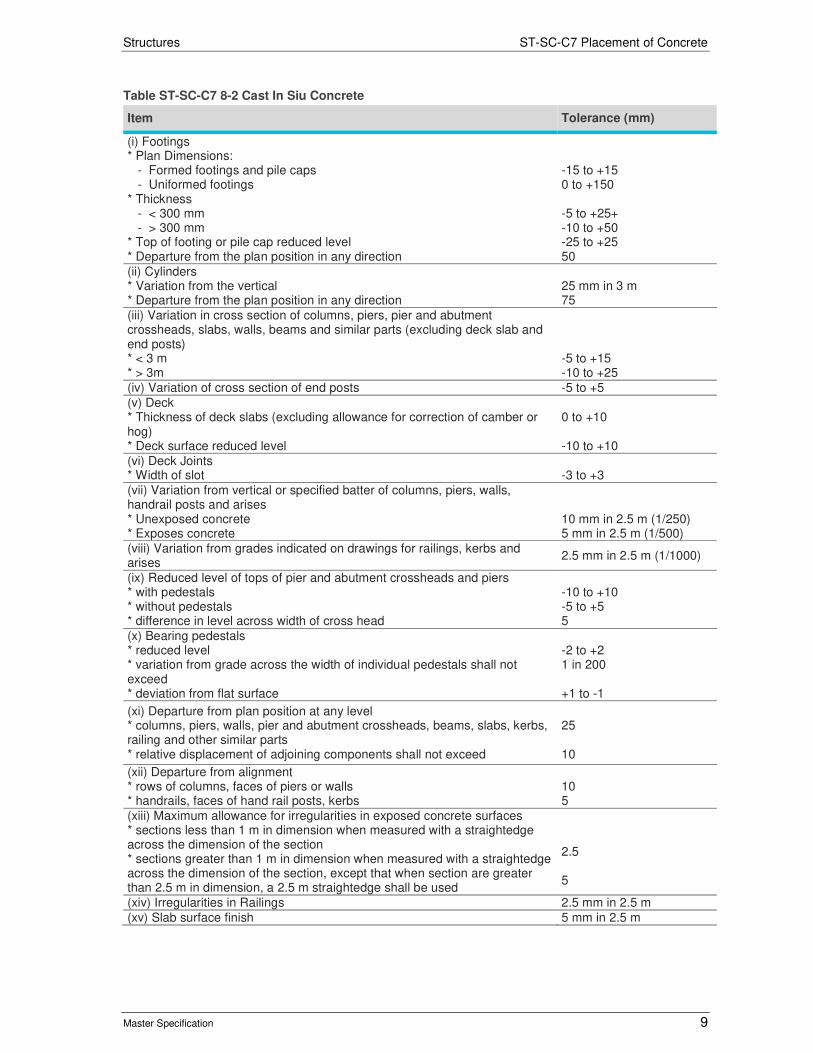
Table ST-SC-C7 8-2 Cast In Siu Concrete
Item Tolerance (mm)
(i) Footings * Plan Dimensions: - Formed footings and pile caps - Uniformed footings * Thickness - < 300 mm - > 300 mm * Top of footing or pile cap reduced level * Departure from the plan position in any direction
-15 to +15 0 to +150 -5 to +25+ -10 to +50 -25 to +25 50
(ii) Cylinders * Variation from the vertical * Departure from the plan position in any direction
25 mm in 3 m 75
(iii) Variation in cross section of columns, piers, pier and abutment crossheads, slabs, walls, beams and similar parts (excluding deck slab and end posts) * < 3 m * > 3m
-5 to +15 -10 to +25
(iv) Variation of cross section of end posts -5 to +5
(v) Deck * Thickness of deck slabs (excluding allowance for correction of camber or hog) * Deck surface reduced level
0 to +10 -10 to +10
(vi) Deck Joints * Width of slot
-3 to +3
(vii) Variation from vertical or specified batter of columns, piers, walls, handrail posts and arises * Unexposed concrete * Exposes concrete
10 mm in 2.5 m (1/250) 5 mm in 2.5 m (1/500)
(viii) Variation from grades indicated on drawings for railings, kerbs and arises
2.5 mm in 2.5 m (1/1000)
(ix) Reduced level of tops of pier and abutment crossheads and piers * with pedestals * without pedestals * difference in level across width of cross head
-10 to +10 -5 to +5 5
(x) Bearing pedestals * reduced level * variation from grade across the width of individual pedestals shall not exceed * deviation from flat surface
-2 to +2 1 in 200 +1 to -1
(xi) Departure from plan position at any level * columns, piers, walls, pier and abutment crossheads, beams, slabs, kerbs, railing and other similar parts * relative displacement of adjoining components shall not exceed
25 10
(xii) Departure from alignment * rows of columns, faces of piers or walls * handrails, faces of hand rail posts, kerbs
10 5
(xiii) Maximum allowance for irregularities in exposed concrete surfaces * sections less than 1 m in dimension when measured with a straightedge across the dimension of the section * sections greater than 1 m in dimension when measured with a straightedge across the dimension of the section, except that when section are greater than 2.5 m in dimension, a 2.5 m straightedge shall be used
2.5 5
(xiv) Irregularities in Railings 2.5 mm in 2.5 m
(xv) Slab surface finish 5 mm in 2.5 m
Structures ST-SC-C7 Placement of Concrete
Master Specification 10
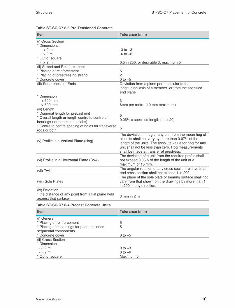
Table ST-SC-C7 8-3 Pre-Tensioned Concrete
Item Tolerance (mm)
(i) Cross Section * Dimensions: - < 2 m - > 2 m * Out of square - > 2 m
-3 to +3 -6 to +6 0.5 in 250, or desirable 3, maximum 5
(ii) Strand and Reinforcement * Placing of reinforcement * Placing of prestressing strand * Concrete cover
5 2 0 to +5
(iii) Squareness of Ends * Dimension - < 500 mm - > 500 mm
Deviation from a plane perpendicular to the longitudinal axis of a member, or from the specified end plane 3 6mm per metre (10 mm maximum)
(iv) Length * Diagonal length for precast unit * Overall length or length centre to centre of bearings (for beams and slabs) * Centre to centre spacing of holes for transverse rods or both
5 0.06% x specified length (max 20) 5
(v) Profile in a Vertical Plane (Hog)
The deviation in hog of any unit from the mean hog of all units shall not vary by more than 0.07% of the length of the units. The absolute value for hog for any unit shall not be less than zero. Hog measurements shall be made at transfer of prestress.
(vi) Profile in a Horizontal Plane (Bow) The deviation of a unit from the required profile shall not exceed 0.06% of the length of the unit or a maximum of 15 mm.
(vii) Twist The angular rotation of any cross section relative to an end cross section shall not exceed 1 in 200.
(viii) Sole Plates The plane of the sole plate or bearing surface shall not vary from that shown on the drawings by more than 1 in 200 in any direction.
(ix) Deviation * the distance of any point from a flat plane held against that surface
3 mm in 2 m
Table ST-SC-C7 8-4 Precast Concrete Units
Item Tolerance (mm)
(i) General * Placing of reinforcement * Placing of sheathings for post-tensioned segmental components * Concrete cover
5 5 0 to +5
(ii) Cross Section * Dimension - < 2 m - > 2 m * Out of square
0 to +3 0 to +6 Maximum 5
Structures ST-SC-C7 Placement of Concrete
Master Specification 11
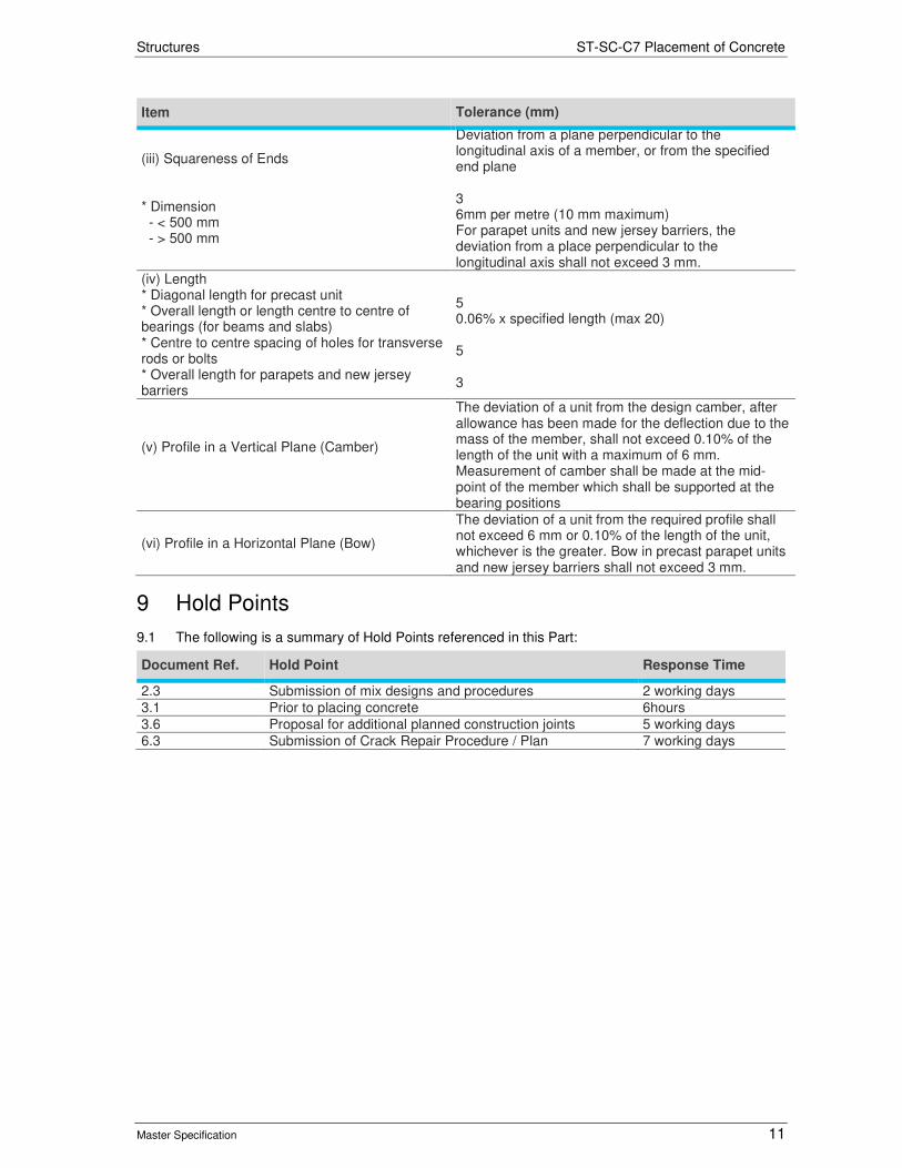
Item Tolerance (mm)
(iii) Squareness of Ends * Dimension - < 500 mm - > 500 mm
Deviation from a plane perpendicular to the longitudinal axis of a member, or from the specified end plane 3 6mm per metre (10 mm maximum) For parapet units and new jersey barriers, the deviation from a place perpendicular to the longitudinal axis shall not exceed 3 mm.
(iv) Length * Diagonal length for precast unit * Overall length or length centre to centre of bearings (for beams and slabs) * Centre to centre spacing of holes for transverse rods or bolts * Overall length for parapets and new jersey barriers
5 0.06% x specified length (max 20) 5 3
(v) Profile in a Vertical Plane (Camber)
The deviation of a unit from the design camber, after allowance has been made for the deflection due to the mass of the member, shall not exceed 0.10% of the length of the unit with a maximum of 6 mm. Measurement of camber shall be made at the mid-point of the member which shall be supported at the bearing positions
(vi) Profile in a Horizontal Plane (Bow)
The deviation of a unit from the required profile shall not exceed 6 mm or 0.10% of the length of the unit, whichever is the greater. Bow in precast parapet units and new jersey barriers shall not exceed 3 mm.
9 Hold Points
9.1 The following is a summary of Hold Points referenced in this Part:
Document Ref. Hold Point Response Time
2.3 Submission of mix designs and procedures 2 working days
3.1 Prior to placing concrete 6hours
3.6 Proposal for additional planned construction joints 5 working days
6.3 Submission of Crack Repair Procedure / Plan 7 working days
Structures ST-SC-C7 Placement of Concrete
Master Specification 12
Figure ST-SC-C7 9-1 Evaporation Rate from Freshly Placed Concrete


![C7 graham session c7 mon1530_v6[2]](https://img.pdfslide.net/doc/110x75/58ed94c51a28ab717c8b475d/c7-graham-session-c7-mon1530v62.jpg)