Embed Size (px)
Citation preview

MASTER SPECIFICATIONS
Division 33 – UTILITIES
Release 1.0 [March] 2017 Released by: Northwestern University Facilities Management Operations 2020 Ridge Avenue, Suite 200 Evanston, IL 60208-4301
All information within this Document is considered CONFIDENTIAL and PROPRIETARY. By receipt and use of this Document, the recipient agrees not to divulge any of the information herein and attached hereto to persons other than those within the recipients’ organization that have specific need to know for the purposes of reviewing and referencing this information. Recipient also agrees not to use this information in any manner detrimental to the interests of Northwestern University.
Northwestern University
Master Specifications
Copyright © 2017
By Northwestern University
These Specifications, or parts thereof, may not be reproduced in any form without
the permission of the Northwestern University.

NORTHWESTERN UNIVERSITY PROJECT NAME ____________ FOR: ___________ JOB # ________ ISSUED: 03/29/2017
MASTER SPECIFICATIONS: DIVISION 33 – UTILITIES
SECTION # TITLE
33 1000 WATER DISTRIBUTION 33 3000 FACILITY SANITARY SEWERS 33 4000 STORM UTILITY DRAINAGE PIPING 33 6300 STEAM ENERGY DISTRIBUTION
** End of List **

NORTHWESTERN UNIVERSITY PROJECT NAME ____________ FOR: ___________ JOB # ________ ISSUED: 03/29/2017
WATER DISTRIBUTION 33 1000 - 1
SECTION 33 1000 - WATER DISTRIBUTION
PART 1 - GENERAL
1.1 RELATED DOCUMENTS
A. Drawings and general provisions of the Contract, including General and Supplementary Conditions and Division 01 Specification Sections, apply to this Section.
B. Comply with most current edition of the Northwestern University Design Standards.
1.2 SUMMARY
A. This Section includes water-distribution piping and related components outside the building from the source to a point 1’-0” above finished floor or 1’-0” inside the exterior wall of the building as shown on the drawings.
B. Utility-furnished products include water meters that will be furnished to the site, ready for installation.
C. Related Sections:
Section 22 1118 “Domestic Water Distribution System.” Section 22 2114 "Plumbing Specialties." Section 22 4000 "Plumbing Fixtures." Section 22 4500 "Plumbing Equipment."
1.3 ACTION SUBMITTALS
A. Product Data: For each type of product indicated.
B. Shop Drawings: Detail precast concrete vault assemblies and indicate dimensions, method of field assembly, and components.
Wiring Diagrams: Power, signal, and control wiring for alarms.
1.4 INFORMATIONAL SUBMITTALS
A. Coordination Drawings: For piping and specialties including relation to other services in same area, drawn to scale. Show piping and specialty sizes and valves, meter and specialty locations, and elevations.
B. Field quality-control test reports.

NORTHWESTERN UNIVERSITY PROJECT NAME ____________ FOR: ___________ JOB # ________ ISSUED: 03/29/2017
WATER DISTRIBUTION 33 1000 - 2
1.5 CLOSEOUT SUBMITTALS
A. Operation and Maintenance Data: For water valves and specialties to include in emergency, operation, and maintenance manuals.
1.6 QUALITY ASSURANCE
A. Regulatory Requirements:
Comply with requirements of utility company supplying water. Include tapping of water mains and backflow prevention.
Comply with standards of authorities having jurisdiction for potable-water-service piping, including materials, installation, testing, and disinfection.
Comply with standards of authorities having jurisdiction for fire-suppression water-service piping, including materials, hose threads, installation, and testing.
B. Piping materials shall bear label, stamp, or other markings of specified testing agency.
1.7 DELIVERY, STORAGE, AND HANDLING
A. Preparation for Transport: Prepare valves, including fire hydrants, according to the following:
Ensure that valves are dry and internally protected against rust and corrosion. Protect valves against damage to threaded ends and flange faces. Set valves in best position for handling. Set valves closed to prevent rattling.
B. During Storage: Use precautions for valves, including fire hydrants, according to the following:
Do not remove end protectors unless necessary for inspection; then reinstall for storage. Protect from weather. Support off the ground or pavement in watertight enclosures when
outdoor storage is necessary.
C. Handling: Use sling to handle valves and fire hydrants if size requires handling by crane or lift. Rig valves to avoid damage to exposed parts. Do not use handwheels or stems as lifting or rigging points.
D. Deliver piping with factory-applied end caps. Maintain end caps through shipping, storage, and handling to prevent pipe-end damage and to prevent entrance of dirt, debris, and moisture.
E. Protect stored piping from moisture and dirt. Elevate above grade.
F. Protect flanges, fittings, and specialties from moisture and dirt.
G. Store plastic piping protected from direct sunlight. Support to prevent sagging and bending.
1.8 PROJECT CONDITIONS
A. Interruption of Existing Water-Distribution Service: Do not interrupt service to facilities occupied by Owner or others unless permitted under the following conditions and then only after arranging to provide temporary water-distribution service according to requirements indicated:

NORTHWESTERN UNIVERSITY PROJECT NAME ____________ FOR: ___________ JOB # ________ ISSUED: 03/29/2017
WATER DISTRIBUTION 33 1000 - 3
Notify Architect, Construction Manager, and Owner no fewer than seven days in advance of proposed interruption of service.
Do not proceed with interruption of water-distribution service without Architect's, Construction Manager's, and Owner's written permission.
Coordinate utility shut down with utility Owner.
1.9 COORDINATION
A. Coordinate connection to water main with utility company.
PART 2 - PRODUCTS
2.1 COPPER TUBE AND FITTINGS
A. Soft Copper Tube: ASTM B 88, Type K, ASTM B 88, Type L and ASTM B 251 water tube, annealed temper.
Copper, Solder-Joint Fittings: ASME B16.18, cast-copper-alloy or ASME B16.22, wrought-copper, solder-joint pressure type. Furnish only wrought-copper fittings if indicated.
Copper, Pressure-Seal Fittings:
a. NPS 2 and Smaller: Wrought-copper fitting with EPDM O-ring seal in each end. b. NPS 2-1/2 to NPS 4: Bronze fitting with stainless-steel grip ring and EPDM O-ring
seal in each end.
B. Bronze Flanges: ASME B16.24, Class 150, with solder-joint end. Furnish Class 300 flanges if required to match piping.
C. Copper Unions: MSS SP-123, cast-copper-alloy, hexagonal-stock body with ball-and-socket, metal-to-metal seating surfaces, and solder-joint or threaded ends.
2.2 DUCTILE-IRON PIPE AND FITTINGS
A. Mechanical-Joint, Ductile-Iron Pipe: AWWA C151, with mechanical-joint bell and plain spigot end unless grooved or flanged ends are indicated.
Mechanical-Joint, Ductile-Iron Fittings: AWWA C110, ductile- or gray-iron standard pattern or AWWA C153, ductile-iron compact pattern.
Glands, Gaskets, and Bolts: AWWA C111, ductile- or gray-iron glands, rubber gaskets, and steel bolts.
B. Push-on-Joint, Ductile-Iron Pipe: AWWA C151, with push-on-joint bell and plain spigot end unless grooved or flanged ends are indicated.
Push-on-Joint, Ductile-Iron Fittings: AWWA C110, ductile- or gray-iron standard pattern or AWWA C153, ductile-iron compact pattern.
Gaskets: AWWA C111, rubber.
C. Grooved-Joint, Ductile-Iron Pipe: AWWA C151, with cut, rounded-grooved ends.

NORTHWESTERN UNIVERSITY PROJECT NAME ____________ FOR: ___________ JOB # ________ ISSUED: 03/29/2017
WATER DISTRIBUTION 33 1000 - 4
Grooved-End, Ductile-Iron Pipe Appurtenances:
a. Grooved-End, Ductile-Iron Fittings: ASTM A 47/A 47M, malleable-iron castings or ASTM A 536, ductile-iron castings with dimensions matching pipe.
b. Grooved-End, Ductile-Iron-Piping Couplings: AWWA C606, for ductile-iron-pipe dimensions. Include ferrous housing sections, gasket suitable for water, and bolts and nuts.
D. Flanges: ASME 16.1, Class 125, cast iron.
2.3 JOINING MATERIALS
A. Brazing Filler Metals: AWS A5.8, BCuP Series.
2.4 PIPING SPECIALTIES
A. Transition Fittings: Manufactured fitting or coupling same size as, with pressure rating at least equal to and ends compatible with, piping to be joined.
B. Tubular-Sleeve Pipe Couplings:
Description: Metal, bolted, sleeve-type, reducing or transition coupling, with center sleeve, gaskets, end rings, and bolt fasteners and with ends of same sizes as piping to be joined.
a. Standard: AWWA C219. b. Center-Sleeve Material: Manufacturer's standard, Carbon steel, Stainless steel,
Ductile iron, or Malleable iron. c. Gasket Material: Natural or synthetic rubber. d. Pressure Rating: 200 psig minimum. e. Metal Component Finish: Corrosion-resistant coating or material.
C. Split-Sleeve Pipe Couplings:
Description: Metal, bolted, split-sleeve-type, reducing or transition coupling with sealing pad and closure plates, O-ring gaskets, and bolt fasteners.
a. Standard: AWWA C219. b. Sleeve Material: Manufacturer's standard, Carbon steel, or Stainless steel. c. Sleeve Dimensions: Of thickness and width required to provide pressure rating. d. Gasket Material: O-rings made of EPDM rubber, unless otherwise indicated. e. Pressure Rating: 200 psig minimum. f. Metal Component Finish: Corrosion-resistant coating or material.
D. Flexible Connectors:
Nonferrous-Metal Piping: Bronze hose covered with bronze wire braid; with copper-tube, pressure-type, solder-joint ends or bronze flanged ends brazed to hose.
Ferrous-Metal Piping: Stainless-steel hose covered with stainless-steel wire braid; with ASME B1.20.1, threaded steel pipe nipples or ASME B16.5, steel pipe flanges welded to hose.

NORTHWESTERN UNIVERSITY PROJECT NAME ____________ FOR: ___________ JOB # ________ ISSUED: 03/29/2017
WATER DISTRIBUTION 33 1000 - 5
2.5 CATHODIC PROTECTION
A. Cathodic Protection shall be per the City of [Evanston , Chicago] Water & Sewer Division Standards.
2.6 GATE VALVES
A. AWWA, Cast-Iron Gate Valves:
Nonrising-Stem, Metal-Seated Gate Valves:
a. Description: Gray- or ductile-iron body and bonnet; with cast-iron or bronze double-disc gate, bronze gate rings, bronze stem, and stem nut.
1) Standard: AWWA C500. 2) Minimum Pressure Rating: 200 psig. 3) End Connections: Mechanical joint. 4) Interior Coating: Complying with AWWA C550.
Nonrising-Stem, Resilient-Seated Gate Valves:
a. Description: Gray- or ductile-iron body and bonnet; with bronze or gray- or ductile-iron gate, resilient seats, bronze stem, and stem nut.
1) Standard: AWWA C509. 2) Minimum Pressure Rating: 200 psig. 3) End Connections: Mechanical joint. 4) Interior Coating: Complying with AWWA C550.
Nonrising-Stem, High-Pressure, Resilient-Seated Gate Valves:
a. Description: Ductile-iron body and bonnet; with bronze or ductile-iron gate, resilient seats, bronze stem, and stem nut.
1) Standard: AWWA C509. 2) Minimum Pressure Rating: 250 psig. 3) End Connections: Push on or mechanical joint. 4) Interior Coating: Complying with AWWA C550.
OS&Y, Rising-Stem, Metal-Seated Gate Valves:
a. Description: Cast- or ductile-iron body and bonnet, with cast-iron double disc, bronze disc and seat rings, and bronze stem.
1) Standard: AWWA C500. 2) Minimum Pressure Rating: 200 psig. 3) End Connections: Flanged.
OS&Y, Rising-Stem, Resilient-Seated Gate Valves:
a. Description: Cast- or ductile-iron body and bonnet, with bronze or gray- or ductile-iron gate, resilient seats, and bronze stem.
NORTHWESTERN UNIVERSITY PROJECT NAME ____________ FOR: ___________ JOB # ________ ISSUED: 03/29/2017
WATER DISTRIBUTION 33 1000 - 6
1) Standard: AWWA C509. 2) Minimum Pressure Rating: 200 psig. 3) End Connections: Flanged.
B. UL/FMG, Cast-Iron Gate Valves:
UL/FMG, Nonrising-Stem Gate Valves:
a. Description: Iron body and bonnet with flange for indicator post, bronze seating material, and inside screw.
1) Standards: UL 262 and FMG approved. 2) Minimum Pressure Rating: 175 psig. End Connections: Flanged.
OS&Y, Rising-Stem Gate Valves:
a. Description: Iron body and bonnet and bronze seating material.
1) Standards: UL 262 and FMG approved. 2) Minimum Pressure Rating: 175 psig). 3) End Connections: Flanged.
C. Bronze Gate Valves:
OS&Y, Rising-Stem Gate Valves:
a. Description: Bronze body and bonnet and bronze stem.
1) Standards: UL 262 and FMG approved. 2) Minimum Pressure Rating: 175 psig. 3) End Connections: Threaded.
Nonrising-Stem Gate Valves:
a. Description: Class 125, Type 1, bronze with solid wedge, threaded ends, and malleable-iron handwheel.
1) Standard: MSS SP-80.
2.7 GATE VALVE ACCESSORIES AND SPECIALTIES
A. Tapping-Sleeve Assemblies:
Description: Sleeve and valve compatible with drilling machine.
a. Standard: MSS SP-60. b. Tapping Sleeve: Cast- or ductile-iron or stainless-steel, two-piece bolted sleeve with
flanged outlet for new branch connection. Include sleeve matching size and type of pipe material being tapped and with recessed flange for branch valve.
c. Valve: AWWA, cast-iron, nonrising-stem, metal or resilient-seated gate valve with one raised face flange mating tapping-sleeve flange.
NORTHWESTERN UNIVERSITY PROJECT NAME ____________ FOR: ___________ JOB # ________ ISSUED: 03/29/2017
WATER DISTRIBUTION 33 1000 - 7
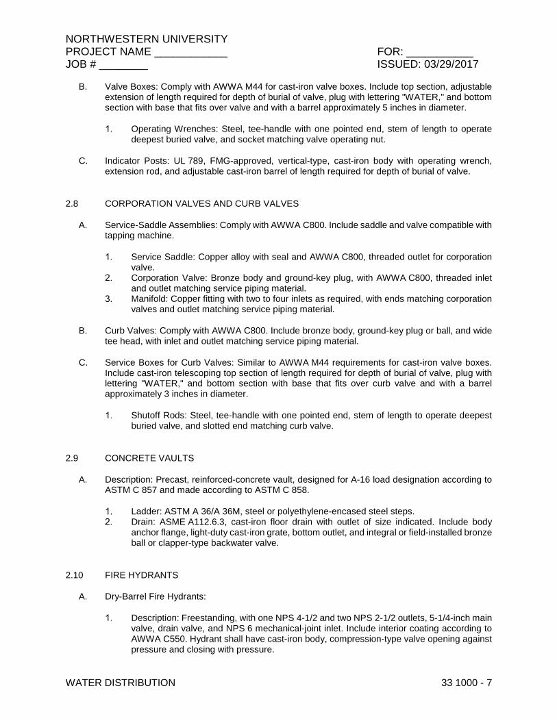
B. Valve Boxes: Comply with AWWA M44 for cast-iron valve boxes. Include top section, adjustable extension of length required for depth of burial of valve, plug with lettering "WATER," and bottom section with base that fits over valve and with a barrel approximately 5 inches in diameter.
Operating Wrenches: Steel, tee-handle with one pointed end, stem of length to operate deepest buried valve, and socket matching valve operating nut.
C. Indicator Posts: UL 789, FMG-approved, vertical-type, cast-iron body with operating wrench, extension rod, and adjustable cast-iron barrel of length required for depth of burial of valve.
2.8 CORPORATION VALVES AND CURB VALVES
A. Service-Saddle Assemblies: Comply with AWWA C800. Include saddle and valve compatible with tapping machine.
Service Saddle: Copper alloy with seal and AWWA C800, threaded outlet for corporation valve.
Corporation Valve: Bronze body and ground-key plug, with AWWA C800, threaded inlet and outlet matching service piping material.
Manifold: Copper fitting with two to four inlets as required, with ends matching corporation valves and outlet matching service piping material.
B. Curb Valves: Comply with AWWA C800. Include bronze body, ground-key plug or ball, and wide tee head, with inlet and outlet matching service piping material.
C. Service Boxes for Curb Valves: Similar to AWWA M44 requirements for cast-iron valve boxes. Include cast-iron telescoping top section of length required for depth of burial of valve, plug with lettering "WATER," and bottom section with base that fits over curb valve and with a barrel approximately 3 inches in diameter.
Shutoff Rods: Steel, tee-handle with one pointed end, stem of length to operate deepest buried valve, and slotted end matching curb valve.
2.9 CONCRETE VAULTS
A. Description: Precast, reinforced-concrete vault, designed for A-16 load designation according to ASTM C 857 and made according to ASTM C 858.
Ladder: ASTM A 36/A 36M, steel or polyethylene-encased steel steps. Drain: ASME A112.6.3, cast-iron floor drain with outlet of size indicated. Include body
anchor flange, light-duty cast-iron grate, bottom outlet, and integral or field-installed bronze ball or clapper-type backwater valve.
2.10 FIRE HYDRANTS
A. Dry-Barrel Fire Hydrants:
Description: Freestanding, with one NPS 4-1/2 and two NPS 2-1/2 outlets, 5-1/4-inch main valve, drain valve, and NPS 6 mechanical-joint inlet. Include interior coating according to AWWA C550. Hydrant shall have cast-iron body, compression-type valve opening against pressure and closing with pressure.

NORTHWESTERN UNIVERSITY PROJECT NAME ____________ FOR: ___________ JOB # ________ ISSUED: 03/29/2017
WATER DISTRIBUTION 33 1000 - 8
a. Standard: AWWA C502. b. Pressure Rating: 150 psig minimum. c. Per City of [Evanston , Chicago] Water & Sewer Division Standards.
B. Wet-Barrel Fire Hydrants:
Description: Freestanding, with one NPS 4-1/2 and two NPS 2-1/2 outlets, NPS 6 threaded or flanged inlet, and base section with NPS 6 mechanical-joint inlet. Include interior coating according to AWWA C550.
a. Standard: AWWA C503. b. Pressure Rating: 150 psig minimum. c. Per City of [Evanston , Chicago] Water & Sewer Division Standards.
2.11 FIRE DEPARTMENT CONNECTIONS
A. Fire Department Connections:
Description: Freestanding, with cast-bronze body, thread inlets according to NFPA 1963 and matching local fire department hose threads, and threaded bottom outlet. Include lugged caps, gaskets, and chains; lugged swivel connection and drop clapper for each hose-connection inlet; 18-inch- high brass sleeve; and round escutcheon plate.
a. Standard: UL 405. b. Connections: Two NPS 2-1/2 inlets and one NPS 4 outlet. c. Inlet Alignment: Inline, horizontal or Square. d. Finish Including Sleeve: Polished bronze. e. Escutcheon Plate Marking: "AUTO SPKR & STANDPIPE." f. Per the City of [Evanston , Chicago] requirements.
PART 3 - EXECUTION
3.1 EARTHWORK
A. Refer to Section 312000 "Earth Moving" for excavating, trenching, and backfilling.
3.2 UTILITY LOCATION
A. Prior to any utility installation work commencing, Contractor shall call JULIE / one-call Illinois locate.
3.3 PIPING APPLICATIONS
A. General: Use pipe, fittings, and joining methods for piping systems according to the following applications.
B. Transition couplings and special fittings with pressure ratings at least equal to piping pressure rating may be used, unless otherwise indicated.

NORTHWESTERN UNIVERSITY PROJECT NAME ____________ FOR: ___________ JOB # ________ ISSUED: 03/29/2017
WATER DISTRIBUTION 33 1000 - 9
C. Do not use flanges or unions for underground piping.
D. Flanges, unions, grooved-end-pipe couplings, and special fittings may be used, instead of joints indicated, on aboveground piping and piping in vaults.
E. Underground water-service piping NPS 2 to NPS 16 shall be the following:
Soft copper tube, ASTM B 88, Type K and B 251; wrought-copper, solder-joint fittings; and brazed joints.
Ductile-iron, push-on-joint pipe; ductile-iron, push-on-joint fittings; and gasketed, or mechanical-joint pipe; ductile-iron, mechanical-joint fittings; and mechanical joints.
F. Underground water-service piping NPS 30 shall be the following:
Ductile-iron, push-on-joint pipe; ductile-iron, push-on-joint fittings; and gasketed, or mechanical-joint pipe; ductile-iron, mechanical-joint fittings; and mechanical joints.
3.4 VALVE APPLICATIONS
A. General Application: Use mechanical-joint-end valves for NPS 3 and larger underground installation. Use threaded- or flanged-end valves for installation in vaults. Use UL/FMG, nonrising-stem gate valves for installation with indicator posts. Use corporation valves and curb valves with ends compatible with piping, for NPS 2 and smaller installation.
B. Drawings indicate valve types to be used. Where specific valve types are not indicated, the following requirements apply:
Underground Valves, NPS 3 and Larger: AWWA, cast-iron, nonrising-stem, metal or resilient-seated gate valves with valve box.
Underground Valves, NPS 4 and Larger, for Indicator Posts: UL/FMG, cast-iron, nonrising-stem gate valves with indicator post.
Use the following for valves in vaults and aboveground:
a. Gate Valves, NPS 2 and Smaller: Bronze, nonrising or rising stem. b. Gate Valves, NPS 3 and Larger: AWWA, cast iron, OS&Y rising stem, metal seated. c. Check Valves: AWWA C508, swing type.
Pressure-Reducing Valves: Use for water-service piping in vaults and aboveground to control water pressure.
Relief Valves: Use for water-service piping in vaults and aboveground.
a. Air-Release Valves: To release accumulated air. b. Air/Vacuum Valves: To release or admit large volume of air during filling of piping. c. Combination Air Valves: To release or admit air.
Detector Check Valves: Use for water-service piping in vaults and aboveground to detect unauthorized use of water.
3.5 PIPING INSTALLATION
A. Water-Main Connection: Arrange with utility company for tap of size and in location indicated in water main.

NORTHWESTERN UNIVERSITY PROJECT NAME ____________ FOR: ___________ JOB # ________ ISSUED: 03/29/2017
WATER DISTRIBUTION 33 1000 - 10
B. Water-Main Connection: Tap water main according to requirements of water utility company and of size and in location indicated.
C. Make connections larger than NPS 2 with tapping machine according to the following:
Install tapping sleeve and tapping valve according to MSS SP-60. Install tapping sleeve on pipe to be tapped. Position flanged outlet for gate valve. Use tapping machine compatible with valve and tapping sleeve; cut hole in main. Remove
tapping machine and connect water-service piping. Install gate valve onto tapping sleeve. Comply with MSS SP-60. Install valve with stem
pointing up and with valve box. Comply with City of [Evanston , Chicago] Water & Sewer Division requirements.
D. Make connections NPS 2 and smaller with drilling machine according to the following:
Install service-saddle assemblies and corporation valves in size, quantity, and arrangement required by utility company standards.
Install service-saddle assemblies on water-service pipe to be tapped. Position outlets for corporation valves.
Use drilling machine compatible with service-saddle assemblies and corporation valves. Drill hole in main. Remove drilling machine and connect water-service piping.
Install corporation valves into service-saddle assemblies. Install manifold for multiple taps in water main. Install curb valve in water-service piping with head pointing up and with service box. Comply with City of [Evanston , Chicago] Water & Sewer Division requirements.
E. Comply with NFPA 24 for fire-service-main piping materials and installation.
Install copper tube and fittings according to CDA's "Copper Tube Handbook."
F. Install ductile-iron, water-service piping according to AWWA C600 and AWWA M41.
G. Bury piping with depth of cover over top at least 66 inches, with top at least 12 inches below level of maximum frost penetration(unless otherwise noted), and according to the following:
H. Install underground piping with restrained joints at horizontal and vertical changes in direction. Use restrained-joint piping, thrust blocks, anchors, tie-rods and clamps, and other supports.
3.6 JOINT CONSTRUCTION
A. Make pipe joints according to the following:
Copper-Tubing, Pressure-Sealed Joints: Use proprietary crimping tool and procedure recommended by copper, pressure-seal-fitting manufacturer.
Ductile-Iron Piping, Gasketed Joints for Water-Service Piping: AWWA C600 and AWWA M41.
Ductile-Iron Piping, Gasketed Joints for Fire-Service-Main Piping: UL 194. Install dielectric fittings in piping at connections of dissimilar metal piping and tubing.
a. Dielectric Fittings for NPS 2 and Smaller: Use dielectric nipples or unions. b. Dielectric Fittings for NPS 2-1/2 to NPS 4: Use dielectric flanges, flange kits or
nipples. c. Dielectric Fittings for NPS 5 and Larger: Use dielectric flange kits.

NORTHWESTERN UNIVERSITY PROJECT NAME ____________ FOR: ___________ JOB # ________ ISSUED: 03/29/2017
WATER DISTRIBUTION 33 1000 - 11
3.7 ANCHORAGE INSTALLATION
A. Anchorage, General: Install water-distribution piping with restrained joints. Anchorages and restrained-joint types that may be used include the following:
Concrete thrust blocks. Locking mechanical joints. Set-screw mechanical retainer glands. Bolted flanged joints. Heat-fused joints. Pipe clamps and tie rods.
B. Install anchorages for tees, plugs and caps, bends, crosses, valves, and hydrant branches. Include anchorages for the following piping systems:
Gasketed-Joint, Ductile-Iron, Water-Service Piping: According to AWWA C600. Gasketed-Joint, PVC Water-Service Piping: According to AWWA M23. Steel Piping; per City of [Evanston , Chicago] Water & Sewer Division Specifications and
Details.
C. Apply full coat of asphalt or other acceptable corrosion-resistant material to surfaces of installed ferrous anchorage devices.
3.8 VALVE INSTALLATION
A. AWWA Gate Valves: Comply with AWWA C600 and AWWA M44. Install each underground valve with stem pointing up and with valve box.
B. AWWA Valves Other Than Gate Valves: Comply with AWWA C600 and AWWA M44.
C. UL/FMG, Gate Valves: Comply with NFPA 24. Install each underground valve and valves in vaults with stem pointing up and with vertical cast-iron indicator post.
D. UL/FMG, Valves Other Than Gate Valves: Comply with NFPA 24.
E. MSS Valves: Install as component of connected piping system.
F. Corporation Valves and Curb Valves: Install each underground curb valve with head pointed up and with service box.
G. Pressure-Reducing Valves: Install in vault or aboveground between shutoff valves.
H. Relief Valves: Comply with AWWA C512. Install aboveground with shutoff valve on inlet.
3.9 DETECTOR-CHECK VALVE INSTALLATION
A. Install in vault or aboveground.
B. Install for proper direction of flow. Install bypass with water meter, gate valves on each side of meter, and check valve downstream from meter.

NORTHWESTERN UNIVERSITY PROJECT NAME ____________ FOR: ___________ JOB # ________ ISSUED: 03/29/2017
WATER DISTRIBUTION 33 1000 - 12
C. Support detector check valves, meters, shutoff valves, and piping on brick or concrete piers.
3.10 WATER METER INSTALLATION
A. Install water meters, piping, and specialties according to utility company's written instructions.
B. Water Meters: Install displacement-type water meters, NPS 2 and smaller, in meter boxes with shutoff valves on water meter inlets. Include valves on water meter outlets and valved bypass around meters unless prohibited by authorities having jurisdiction.
C. Water Meters: Install compound-type water meters, NPS 3 and larger, in meter vaults. Include shutoff valves on water meter inlets and outlets and valved bypass around meters. Support meters, valves, and piping on brick or concrete piers.
3.11 BACKFLOW PREVENTER INSTALLATION
A. Install backflow preventers of type, size, and capacity indicated. Include valves and test cocks. Install according to requirements of plumbing and health department and authorities having jurisdiction.
B. Do not install backflow preventers that have relief drain in vault or in other spaces subject to flooding.
C. Do not install bypass piping around backflow preventers.
D. Support NPS 2-1/2 and larger backflow preventers, valves, and piping near floor and on brick or concrete piers.
3.12 WATER METER BOX INSTALLATION
A. Install water meter boxes in paved areas flush with surface.
B. Install water meter boxes in grass or earth areas with top 2 inches above surface.
3.13 CONCRETE VAULT INSTALLATION
A. Install precast concrete vaults according to ASTM C 891.
3.14 FIRE HYDRANT INSTALLATION
A. General: Install each fire hydrant with separate gate valve in supply pipe, anchor with restrained joints or thrust blocks, and support in upright position.
B. Wet-Barrel Fire Hydrants: Install with valve below frost line. Provide for drainage.
C. AWWA Fire Hydrants: Comply with AWWA M17.
D. UL/FMG Fire Hydrants: Comply with NFPA 24.

NORTHWESTERN UNIVERSITY PROJECT NAME ____________ FOR: ___________ JOB # ________ ISSUED: 03/29/2017
WATER DISTRIBUTION 33 1000 - 13
3.15 FIRE DEPARTMENT CONNECTION INSTALLATION
A. Install ball drip valves at each check valve for fire department connection to mains.
B. Install protective pipe bollards on two sides of each fire department connection.
3.16 CONNECTIONS
A. Connect water-distribution piping to existing water main. Use tapping sleeve and tapping valve or method approved by the Water & Sewer Division.
3.17 FIELD QUALITY CONTROL
A. Piping Tests: Conduct piping tests before joints are covered and after concrete thrust blocks have hardened sufficiently. Fill pipeline 24 hours before testing and apply test pressure to stabilize system. Use only potable water.
B. Hydrostatic Tests: Test at not less than one-and-one-half times working pressure for two hours.
Increase pressure in 50-psig increments and inspect each joint between increments. Hold at test pressure for 1 hour; decrease to 0 psig. Slowly increase again to test pressure and hold for 1 more hour. Maximum allowable leakage is 2 quarts per hour per 100 joints. Remake leaking joints with new materials and repeat test until leakage is within allowed limits.
C. Prepare reports of testing activities.
3.18 IDENTIFICATION
A. Install continuous underground detectable warning tape during backfilling of trench for underground water-distribution piping. Locate below finished grade, directly over piping. Underground warning tapes are specified in Section 312000 "Earth Moving."
3.19 CLEANING
A. Clean and disinfect water-distribution piping as follows:
Purge new water-distribution piping systems and parts of existing systems that have been altered, extended, or repaired before use.
Use purging and disinfecting procedure prescribed by authorities having jurisdiction or, if method is not prescribed by authorities having jurisdiction, use procedure described in NFPA 24 for flushing of piping. Flush piping system with clean, potable water until dirty water does not appear at points of outlet.
Use purging and disinfecting procedure prescribed by authorities having jurisdiction or, if method is not prescribed by authorities having jurisdiction, use procedure described in AWWA C651 or do as follows:
a. Fill system or part of system with water/chlorine solution containing at least 50 ppm of chlorine; isolate and allow to stand for 24 hours.

NORTHWESTERN UNIVERSITY PROJECT NAME ____________ FOR: ___________ JOB # ________ ISSUED: 03/29/2017
WATER DISTRIBUTION 33 1000 - 14
b. Drain system or part of system of previous solution and refill with water/chlorine solution containing at least 200 ppm of chlorine; isolate and allow to stand for 3 hours.
c. After standing time, flush system with clean, potable water until no chlorine remains in water coming from system.
d. Submit water samples in sterile bottles to authorities having jurisdiction. Repeat procedure if biological examination shows evidence of contamination.
B. Prepare reports of purging and disinfecting activities.
END OF SECTION 33 1000

NORTHWESTERN UNIVERSITY PROJECT NAME ____________ FOR: ___________ JOB # ________ ISSUED: 03/29/2017
FACILITY SANITARY SEWERS 33 3000 - 1
SECTION 33 3000 – FACILITY SANITARY SEWERS
PART 1 - GENERAL
1.1 RELATED DOCUMENTS
A. Drawings and general provisions of the Contract, including General and Supplementary Conditions and Division 01 Specification sections, apply to this section.
B. Comply with most current edition of the Northwestern University Design Standards.
1.2 SUMMARY
A. Provide all labor, materials and equipment as necessary to complete all work as indicated on the Drawings and specified herein. Review specific project requirements with NU during the design phase.
B. This Section includes:
1. Pipe and fittings. 2. Non-pressure and pressure couplings. 3. Expansion joints and deflection fittings. 4. Backwater valves. 5. Cleanouts. 6. Encasement for piping. 7. Manholes.
1.3 DEFINITIONS:
1. DIP: Ductile Iron Pipe 2. PVC: Polyvinyl chloride plastic pipe
1.4 REGULATORY REQUIREMENTS: COMPLY WITH THE METROPOLITAN WATER RECLAMATION DISTRICT
A. (MWRD) requirements, including inspections prior to and during work.
1.5 PERFORMANCE REQUIREMENTS:
A. Pressure pipe pressure ratings: At least equal to system operating pressure, but not less than 150 psig.
NORTHWESTERN UNIVERSITY PROJECT NAME ____________ FOR: ___________ JOB # ________ ISSUED: 03/29/2017
FACILITY SANITARY SEWERS 33 3000 - 2
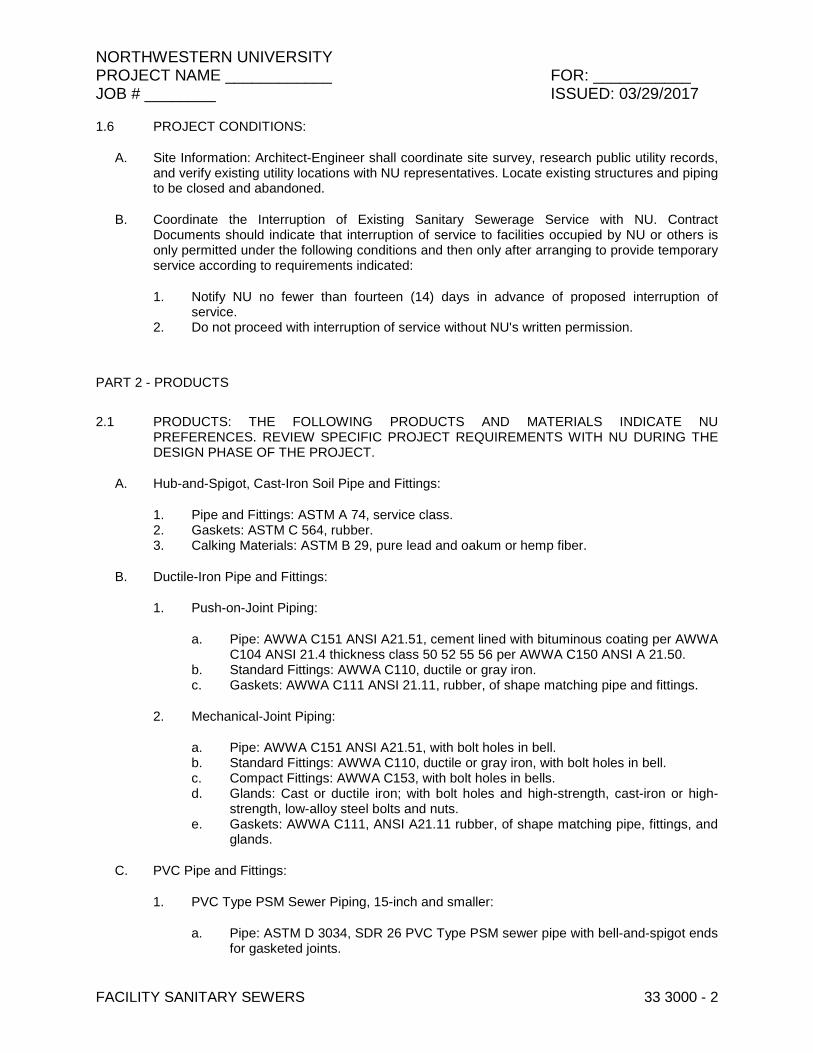
1.6 PROJECT CONDITIONS:
A. Site Information: Architect-Engineer shall coordinate site survey, research public utility records, and verify existing utility locations with NU representatives. Locate existing structures and piping to be closed and abandoned.
B. Coordinate the Interruption of Existing Sanitary Sewerage Service with NU. Contract Documents should indicate that interruption of service to facilities occupied by NU or others is only permitted under the following conditions and then only after arranging to provide temporary service according to requirements indicated:
1. Notify NU no fewer than fourteen (14) days in advance of proposed interruption of service.
2. Do not proceed with interruption of service without NU's written permission.
PART 2 - PRODUCTS
2.1 PRODUCTS: THE FOLLOWING PRODUCTS AND MATERIALS INDICATE NU PREFERENCES. REVIEW SPECIFIC PROJECT REQUIREMENTS WITH NU DURING THE DESIGN PHASE OF THE PROJECT.
A. Hub-and-Spigot, Cast-Iron Soil Pipe and Fittings:
1. Pipe and Fittings: ASTM A 74, service class. 2. Gaskets: ASTM C 564, rubber. 3. Calking Materials: ASTM B 29, pure lead and oakum or hemp fiber.
B. Ductile-Iron Pipe and Fittings:
1. Push-on-Joint Piping:
a. Pipe: AWWA C151 ANSI A21.51, cement lined with bituminous coating per AWWA C104 ANSI 21.4 thickness class 50 52 55 56 per AWWA C150 ANSI A 21.50.
b. Standard Fittings: AWWA C110, ductile or gray iron. c. Gaskets: AWWA C111 ANSI 21.11, rubber, of shape matching pipe and fittings.
2. Mechanical-Joint Piping:
a. Pipe: AWWA C151 ANSI A21.51, with bolt holes in bell. b. Standard Fittings: AWWA C110, ductile or gray iron, with bolt holes in bell. c. Compact Fittings: AWWA C153, with bolt holes in bells. d. Glands: Cast or ductile iron; with bolt holes and high-strength, cast-iron or high-
strength, low-alloy steel bolts and nuts. e. Gaskets: AWWA C111, ANSI A21.11 rubber, of shape matching pipe, fittings, and
glands.
C. PVC Pipe and Fittings:
1. PVC Type PSM Sewer Piping, 15-inch and smaller:
a. Pipe: ASTM D 3034, SDR 26 PVC Type PSM sewer pipe with bell-and-spigot ends for gasketed joints.

NORTHWESTERN UNIVERSITY PROJECT NAME ____________ FOR: ___________ JOB # ________ ISSUED: 03/29/2017
FACILITY SANITARY SEWERS 33 3000 - 3
b. Fittings: ASTM D 3034, PVC with bell ends. c. Gaskets: ASTM F 477, elastomeric seals.
2. PVC Type PSM Sewer Piping,18-inch and larger:
a. Pipe: ASTM F 679, T-1 wall thickness, bell and spigot for gasketed joints. b. Fittings: ASTM F679 c. Gaskets: ASTM F 477, elastomeric seals.
3. PVC Pressure Piping:
a. Pipe: AWWA C900, Class 150 Class 200 PVC pipe with bell-and spigot ends for gasketed joints.
b. Fittings: AWWA C900, Class 150 Class 200 PVC pipe with bell ends. c. Gaskets: ASTM F 477, elastomeric seals. d. Ductile-Iron, Compact Fittings: AWWA C153, for push-on joints. e. Gaskets for Ductile-Iron Fittings: AWWA C111, rubber.
D. Non-Pressure-Type Transition Couplings:
1. Comply with ASTMC 1173, elastomeric, sleeve-type, reducing or transition coupling, for joining underground non-pressure piping. Include ends of same sizes as piping to be joined and corrosion-resistant-metal tension band and tightening mechanism on each end.
2. Sleeve Materials:
a. For Cast-Iron Soil Pipes: ASTM C 564, rubber. b. For Plastic Pipes: ASTM F 477, elastomeric seal or ASTM D 926, PVC. c. For Dissimilar Pipes: ASTM D 5926, PVC or other material compatible with pipe
materials being joined.
E. Unshielded, Flexible Couplings: Elastomeric sleeve with stainless steel corrosion-resistant-metal tension band and tightening mechanism on each end.
F. Shielded, Flexible Couplings: ASTM C 1460, elastomeric or rubber sleeve with full-length, corrosion-resistant stainless steel outer shield and corrosion-resistant stainless steel tension band and tightening mechanism on each end.
G. Pressure-Type Pipe Couplings:
1. Metal, bolted, mechanical joint sleeve, reducing or transition coupling, for joining underground pressure piping. Include 200-psig minimum pressure rating and ends of same sizes as piping to be joined.
a. Gasket Material: Natural or synthetic rubber. b. Metal Component Finish: Corrosion-resistant coating or material.
H. Ductile-Iron Deflection Fittings: Compound coupling fitting with ball joint, flexing section, gaskets, and restrained-joint ends complying with AWWA C110 or AWWA C153. Include rating for 250-psig minimum working pressure and for up to 15 degrees of deflection.
I. Backwater Valves:

NORTHWESTERN UNIVERSITY PROJECT NAME ____________ FOR: ___________ JOB # ________ ISSUED: 03/29/2017
FACILITY SANITARY SEWERS 33 3000 - 4
1. Cast-Iron Backwater Valves: ASME A112.14.1, gray-iron body and bolted cover, with bronze seat.
2. PVC Backwater Valves: Horizontal type; with PVC body, PVC removable cover, and PVC swing check valve.
J. Cleanouts:
1. Cast-Iron Cleanouts: ASME A112.36.2M, round, gray-iron housing with clamping device and round, secured, scoriated, gray-iron cover. Include gray-iron ferrule with inside calk or spigot connection and countersunk, tapered-thread, brass closure plug.
a. Top-Loading Classifications: Heavy Duty. b. Sewer Pipe Fitting and Riser to Cleanout: ASTM A 74, Service class, cast-iron soil
pipe and fittings.
2. PVC Cleanouts: PVC body with PVC threaded plug. Include PVC sewer pipe fitting and riser to cleanout of same material as sewer piping.
K. Encasement for Piping:
1. Standard: ASTM A 674 or AWWA C105. 2. Material: polyethylene film of 0.008-inch (0.20-mm) minimum thickness. 3. Form: Sheet or tube. 4. Color: Black or natural.
a. Standard Precast Concrete Manholes: ASTM C 478, precast, reinforced concrete, of depth indicated, with provision for sealant joints.
5. Ballast: Increase thickness of precast concrete sections or add concrete to base section, as required to prevent flotation.
6. Riser Sections: Of length to provide depth indicated. 7. Top Section: Eccentric-cone type unless flat-slab-top type is required; with top of cone of
size that matches grade rings. 8. Section Joint Sealant: ASTM C 443 rubber gasket. 9. Resilient Pipe Connectors: ASTM C 923 rubber boot, cast or fitted into manhole walls, for
each pipe connection. Boot shall result in a water tight connection conforming to the performance requirements of ASTM C 443.
10. Steps: Cast Iron steps conforming to the performance standards of ASTM C 478. Omit steps if total depth from floor of manhole to finished grade is less than 48. Cast or anchor steps into sidewalls at 16-inch intervals inches.
11. Grade (Adjusting) Rings: Reinforced-concrete rings, with diameter matching manhole frame and cover, and with height as required to adjust manhole frame and cover to indicated elevation and slope. Maximum per Drawings.
L. Manhole Frames and Covers: Include indented top design with lettering cast into cover, using wording equivalent to "SANITARY SEWER."
1. Material: ASTM A 48, Class 35 gray ASTM A 536, Grade 60-40-18 ductile iron unless otherwise indicated.
M. Manhole-Cover Inserts: Manufactured, plastic form, of size to fit between manhole frame and cover and designed to prevent stormwater inflow. Include handle for removal and gasket for gastight sealing.

NORTHWESTERN UNIVERSITY PROJECT NAME ____________ FOR: ___________ JOB # ________ ISSUED: 03/29/2017
FACILITY SANITARY SEWERS 33 3000 - 5
1. Type: Solid.
N. External Chimney Seal: Rubber sleeves shall be extruded from a high grade rubber compound meeting the applicable requirements of ASTM C923. Sleeves shall be double or triple pleated with a minimum unexpanded vertical height of 8 inches, a minimum thickness of 3/16 inch, capable of expanding not less than 2 inches vertically when installed.
1. Screws, bolts and nuts: Stainless steel, ASTM F-593 and 594 Type 304. 2. Expansion Bands shall be16 gauge thickness, 1-3/4 inches wide and made of stainless
steel meeting the requirements of ASTM A240, Type 304.
O. Protective Coatings: One- or two-coat, coal-tar epoxy; 15-mil minimum thickness, unless otherwise indicated; factory or field applied to the exterior and interior surfaces.
P. Manhole Channels and Benches: Factory or field formed from concrete. Portland cement design mix, 4000 psi minimum. Include channels and benches in manholes.
1. Channels: Concrete invert, formed to same width as connected piping, with height of vertical sides to three-fourths of pipe diameter. Form curved channels with smooth, uniform radius and slope.
2. Invert Slope: 1 percent through manhole. 3. Benches: Concrete, sloped to drain into channel. 4. Slope: 8 percent.
PART 3 - EXECUTION
3.1 EARTHWORK
A. Refer to Section 312000 "Earth Moving" for excavating, trenching, and backfilling.
3.2 UTILITY LOCATION
A. Prior to any utility installation work commencing, Contractor shall call JULIE / one-call Illinois locate.
3.3 INSPECTIONS
A. Require inspection and report by Contractor of interior of piping to determine whether line displacement or other damage has occurred. Inspection should occur after approximately 24 inches of backfill is in place, and again at completion of Project.
1. Contractor shall submit separate report for each system inspection. 2. Defects requiring correction include the following:
a. Alignment: Less than full diameter of inside of pipe is visible between structures. b. Deflection: Flexible piping with deflection that prevents passage of ball or cylinder
of size not less than 92.5 percent of piping diameter. c. Damage: Crushed, broken, cracked, or otherwise damaged piping. d. Infiltration: Water leakage into piping. e. Exfiltration: Water leakage from or around piping.

NORTHWESTERN UNIVERSITY PROJECT NAME ____________ FOR: ___________ JOB # ________ ISSUED: 03/29/2017
FACILITY SANITARY SEWERS 33 3000 - 6
3. Contractor shall replace defective piping using new materials, and repeat inspections until defects are within allowances specified.
4. Contractor shall reinspect and repeat procedure until results are satisfactory.
3.4 PREPARATION
A. Sanitary sewer pipes:
1. Refer to Section 31 20 00, Earth Moving, requirements. 2. For all rigid pipe installations, the width of the trench at the top of the pipe shall not
exceed the outside pipe diameter, including bells, plus the clear width on each side of the pipe as listed in Table 33 30 00-1:
Table 33 30 00-1
Pipe Size (in)
Maximum Clear Width (in)
6 – 24 12
27 – 54 15
60 and over 24
3. For all non-rigid pipe installations, the minimum trench width shall be per the pipe manufacturer’s recommendations, but at no time shall the width be less than that specified in ASTM D2321.
4. The length of trench or tunnel open at any one time shall conform to the limits approved by NU. In general, not more than 100 feet of trench shall be opened in advance of the completed work.
5. Where the sewer pipes are built upon the surface of the ground, the surface shall be grubbed and cleared of all stumps, grass, muck, or other vegetable matter.
6. Pipes shall not be constructed on frozen ground.
B. Manholes:
1. Refer to Section 31 20 00, Earth Moving requirements.
3.5 SANITARY SEWER PIPE INSTALLATION
A. Pipe shall be laid accurately to the line and grade designated on the Contract Drawings. Pipe shall be carefully centered so that when laid it will form a sewer with close fitting joints and a uniform invert.
B. All pipe shall begin and end with pipe ends as normally fabricated by the manufacturers. If field cutting pipe is required, cutting shall be performed by the use of tools or equipment that will provide a neat perpendicular cut with a beveled end without structural damage to the pipe wall or damage to coatings or fillers.
C. For Ductile Iron pipes:
1. Installation of ductile iron pipes shall conform to AWWA C600 unless otherwise noted on Contract Documents.
2. Remove and replace defective pieces. 3. Clear of all debris and dirt before installing and keep clean until accepted.

NORTHWESTERN UNIVERSITY PROJECT NAME ____________ FOR: ___________ JOB # ________ ISSUED: 03/29/2017
FACILITY SANITARY SEWERS 33 3000 - 7
4. For push-on joints, clean bell of excess tar or other obstruction and wipe out before inserting next pipe spigot. Shove pipe into place until properly seated and hold securely until joint completed.
5. Temporary Plugs: When pipe laying not in progress, close open ends of pipe with temporary watertight plugs. If water in trench, do not remove plug until danger of water entering pipe passed.
6. Appurtenances: Set fittings and appurtenances as indicated on Contract Drawings. 7. Polyethylene wrapping: All buried ductile iron piping shall be polyethylene wrapped in
accordance with pipe manufacturer’s written instruction.
D. For PVC pipes:
1. Installation of all sizes of PVC pipe shall conform to ASTM D2321 unless otherwise noted on Contract Documents.
2. Factory made fittings must be used on all house connections or other connections. Bedding material for house connections (sanitary sewer house laterals) shall be equal to that of the main sewer. Risers in deep or unstable trenches shall be embedded in Class I materials only. Brackets or anchors shall be used to hold end caps or plugs in place on sanitary sewers and house laterals for the purpose of withstanding air testing pressures. Caps or plugs shall not be chemically-welded in place.
3. Remove and replace defective pieces. 4. Clear of all debris and dirt before installing and keep clean until accepted.
E. Joining pipes:
1. Before joining pipe with a coupling or bell end, all surfaces of the portions of the pipe to be joined and all surfaces of factory made jointing materials shall be clean and dry. Lubricants, primers, adhesives, solvents, bolts, etc. shall have been manufactured specifically for their intended use and shall be used as recommended by the pipe and/or pipe joint manufacturer. The jointing materials shall be fitted and adjusted or applied in such a manner as to obtain a close fitting joint and to obtain the degree of water tightness required.
2. Where the joining of pipes of different materials is required or approved, this work shall be done utilizing special adapters and couplers manufactured specifically for this purpose. The adapters and couplers shall be installed and securely attached to both pipe barrels according to manufacturers’ recommendations.
3. As soon as possible after a joint is made, sufficient backfill materials shall be placed along each side of the pipe to support the pipe in its final position.
4. Where a pipe stub or run of pipe is to be temporarily terminated for future extension, the end of the pipe shall be sealed using an approved removable plug.
F. Where required by the Contract Drawings, flexible pipe shall be elongated by increasing its vertical diameter by five percent. The vertical elongation shall be maintained by horizontal wire struts that shall be left in place until the embankment is completed. The struts shall be removed as directed by NU.
3.6 PRECAST CONCRETE MANHOLE INSTALLATION
A. CONTRACTOR shall submit to NU the following:
1. Manufacturer's name and address 2. Detailed shop drawings 3. Material specifications

NORTHWESTERN UNIVERSITY PROJECT NAME ____________ FOR: ___________ JOB # ________ ISSUED: 03/29/2017
FACILITY SANITARY SEWERS 33 3000 - 8
B. Approval will be based on complete inspection of manufacturer's plant, method of manufacture, samples of materials to be used and inspection and testing of actual units to be used.
C. Excavation and backfill shall be in accordance with Section 31 20 00, Earth Moving.
D. The manhole bottom shall have a uniform bearing on a minimum of three inches of compacted #57 stone. Unsuitable material shall be removed and replaced as specified in Section 31 20 00, Earth Moving.
E. Adequate precautions shall be taken to prevent concrete and/or mortar from freezing. Any material incorporated in these items having a temperature of 40 degrees F or less shall not be placed until heated for a period sufficient to ensure a temperature of 50 degrees F to 80 degrees F throughout the entire mass of the material. Refer to Section 03 30 00, Cast-in-Place Concrete for additional requirements.
F. Standard manhole steps shall be set in the cones of precast manholes as indicated on the Contract Drawings. Where the ordinance grade is below the grade of an unimproved street, the last precast section shall be built to correspond with the ordinance grade, and the manhole casting and cover set to existing grade by use of a brick chimney and/or grade rings. The inside diameter of the precast section shall be not less than 26 inches nor more than 28 inches.
G. All manholes shall be thoroughly bonded or securely connected to the barrel of the sewer, and all connections with pipes neatly made without projections or voids. Unless otherwise noted on the Contract Drawings, all pipe connected to precast concrete manholes shall be sealed by use of a resilient manhole connector meeting the requirements of ASTM C923.
H. When manholes are completed, they shall be cleared of scaffolding, centering or forms and cleaned of surplus mortar or other foreign materials.
I. Manholes on sanitary sewers shall be tested by CONTRACTOR. Testing shall be performed in accordance with ASTM C1244.
3.7 REPAIR/RESTORATION
A. All surfaces affected by the construction work shall be permanently restored according to Section 01 74 00, Cleaning.
B. Before Final Completion, CONTRACTOR shall clean up the Work area in accordance with Section 01 74 00, Cleaning.
3.8 FIELD TESTING
A. General:
1. Remove all dirt, dust, oil, grease and other foreign material before initiating testing and acceptance procedures.
2. Perform leakage tests and measurements according to applicable standards. 3. Contractor shall test new piping systems, and parts of existing systems that have been
altered, extended, or repaired, for leaks and defects. 4. Contractor shall not enclose, cover, or put into service before inspection and approval. 5. Contractor shall test completed piping systems according to requirements of authorities
having jurisdiction.

NORTHWESTERN UNIVERSITY PROJECT NAME ____________ FOR: ___________ JOB # ________ ISSUED: 03/29/2017
FACILITY SANITARY SEWERS 33 3000 - 9
6. Contractor shall schedule tests and inspections by authorities having jurisdiction with at least 24 hours' advance notice.
7. Contractor shall submit separate report for each test.
A. Low Pressure Air Test:
1. All sewers, manholes or other structures and appurtenances which are to be used for sanitary sewage shall at all times be water tight and not permit the infiltration of water into, or the exfiltration of sewage therefrom. All such sewers shall be subject to an air leakage test to be performed by CONTRACTOR, under the direct observation of NU, unless otherwise noted. No request by CONTRACTOR for waiver of the test will be considered. The cost of all air-leakage testing shall be included in the unit price bid for the pipe.
2. The air test shall be performed within a reasonable time after completion of the sewer, or sections of a large portion of the sewer installation, before the Substantial Completion. CONTRACTOR shall verify that the sewers, manholes, etc. are substantially complete and reasonably clean prior to performing the test.
3. The testing procedure and criteria shall be in accordance with UNI-B-6, ASTM C828 (clay pipe – for pipe up to 42-inch diameter), C924 (concrete pipe and ductile iron pipe – for pipe sizes up to 24-inch diameter), or F1417 (plastic pipe), as applicable, and Table 33 30 00-2 which shows the minimum test time in minutes per 100 feet of pipe for each nominal pipe size for a 1.0 psi pressure drop from 3.5 to 2.5 psi. Testing procedures and criteria for PVC pipe shall be in accordance with ASTM D3212. All sanitary sewer manholes shall be tested in accordance with ASTM C1244.
Table 33 30 00-2
Nominal Pipe Size (in)
Time, T (min/100 ft)
Nominal Pipe Size (in)
Time, T (min/100 ft)
3 0.2 21 3.0
4 0.3 24 3.6
6 0.7 27 4.2
8 1.2 30 4.8
10 1.5 33 5.4
12 1.8 36 6.0
15 2.1 39 6.6
18 2.4 42 7.3
4. If the sewer fails to meet the minimum test times shown in Table 33 30 00-2, NU may order CONTRACTOR to expose and repair as required joints or any section in the test, backfill, and restore the surface. Such additional work shall be at CONTRACTOR's expense. Following the repairs, the sewer shall be retested until the minimum test time is equaled or exceeded.
5. In the event that the pipe fails to meet the test requirements, no payment to exceed 75 percent of the price bid for the pipe items shall be made until the sewer(s) satisfactorily passes the low pressure air test. Passing an air test or making repairs and passing an air test does not release CONTRACTOR from the responsibility of repair or replacement of sewers and appurtenances during the Warranty Period.
B. Individual Joint Test:

NORTHWESTERN UNIVERSITY PROJECT NAME ____________ FOR: ___________ JOB # ________ ISSUED: 03/29/2017
FACILITY SANITARY SEWERS 33 3000 - 10
1. For CCFRPM pipe 48-inch diameter or larger, individual joint testing shall conform with ASTM C1103.
2. For reinforced concrete pipe 27-inch diameter or larger, individual joint testing shall conform with ASTM C1103.
C. Hydrostatic Tests: Contractor shall test sanitary sewerage according to requirements of authorities having jurisdiction and per Exfiltration and Infiltration Method Procedures per the Standard Specifications for Water and Sewer Construction in Illinois latest edition where no separate written standards exist.
D. Force Main: Perform hydrostatic test after thrust blocks, supports, and anchors have hardened. Test at pressure not less than 1-1/2 times the maximum system operating pressure, but not less than 150 psig.
E. Ductile-Iron Piping: Test according to AWWA C600, "Hydraulic Testing" Section.
F. PVC Piping: Test according to AWWA M23, "Testing and Maintenance" Chapter.
G. Manholes: Perform hydraulic test according to ASTM C 969.
H. Leaks and loss in test pressure constitute defects that must be repaired.
I. Deflection Tests:
1. All sewers constructed using non-rigid pipe materials shall be subject to a pipe deflection test, regardless of the pipe stiffness, to be performed by CONTRACTOR, under the direct supervision of NU. No request by CONTRACTOR for waiver of the test will be considered. The cost of performing the deflection testing shall be included in the unit price bid for the pipe.
2. The deflection test will be performed at the end of the Warranty Period before release of the retainer or bond.
3. The test shall consist of pulling a mandrel (Go/No Go) device through the sewer by hand. No mechanical pulling devices shall be used. The mandrel shall be either the full circle or 9-arm type and conform to the dimensions noted in Table 33 30 00-3. No sewer will be accepted if the pipe deflection at any point is in excess of 5 percent of its average inside diameter as noted in Table 33 30 00-3, where T-1 equals Cell Classification 12454C and T-2 equals Cell Classification 12364C.
Table 33 30 00-3
ASTM D-3034 ASTM D-2680 ASTM F-679
Minimal Pipe Size (in)
Average I.D. (in)
5% Deflection Mandrel
(in)
Average I.D. (in)
5% Deflection Mandrel
(in)
Average I.D. (in)
5% Deflection Mandrel
(in)
6 5.893 5.598
8 7.891 7.496 7.75 7.35
10 9.864 9.371 9.75 9.25
12 11.737 11.150 11.75 11.16
15 14.374 13.655 14.75 14.01
T-1
18 18.165 17.257
21 21.415 20.344

NORTHWESTERN UNIVERSITY PROJECT NAME ____________ FOR: ___________ JOB # ________ ISSUED: 03/29/2017
FACILITY SANITARY SEWERS 33 3000 - 11
24 24.092 22.887
27 27.152 25.794
T-2
18 18.202 17.292
21 21.459 20.386
24 24.142 22.935
27 27.208 25.848
4. All portions of sewer found to exceed this limit shall be replaced or repaired by CONTRACTOR promptly in a manner satisfactory to NU. After a period of at least 60 days after backfilling the repaired area(s), the sewer shall again be tested for deflection. This procedure shall be repeated as necessary until the maximum pipe deflection is 5 percent or less. CONTRACTOR shall bear the total cost of all repairs or replacement, including surface restoration in accordance with Section 01 74 00, Cleaning.
J. Closed Caption Television (CCTV) Inspection:
1. All sewers, manholes, inlets and other appurtenances shall be subject to CCTV and visual inspections, to be performed by CONTRACTOR, prior to Substantial Completion of the sewer items. No request by CONTRACTOR for waiver of the inspections will be considered.
2. The CCTV inspections shall be performed after completion of the sewer items, before the Substantial Completion and release of the retainer or bond. CONTRACTOR shall verify that the sewers and manholes are substantially complete and reasonably clean prior to performing the inspection.
3. CCTV inspections shall be performed in accordance with National Association of Sewer Service Companies (NASSCO) Pipeline Assessment Certification Program (PACP), latest edition.
4. All pipe, manholes, and appurtenances found to be defective shall be replaced or repaired by CONTRACTOR promptly in a manner satisfactory to NU. CONTRACTOR shall bear the total cost of all repairs or replacement, including surface restoration.
5. Passing the CCTV inspection or making repairs and passing the CCTV inspection does not release CONTRACTOR from the responsibility of repair or replacement of sewers and appurtenances during the Warranty Period.
6. Submit the following information to the City prior to Substantial Completion:
a. Database file with inspection event and defect records in Microsoft Access (.MDB) (Granite native export database, PACP 4.2 schema-compliant database, or accepted equal)
b. Video file: MPEG (.mpg) or Windows Media file (.wmv). One video file per pipe inspection.
c. Inspection report: One report in Adobe Acrobat PDF format per pipe inspection. Report should include:
1) Inspection header info (who, what, where, when) 2) Defect log 3) Photos of defects
d. Defect photos: screen captures from the video (.jpg) e. Use the “Asset IDs” provided in the plans when referencing “start manhole,” “end
manhole,” and “pipe segment” in the inspection database and filenames.

NORTHWESTERN UNIVERSITY PROJECT NAME ____________ FOR: ___________ JOB # ________ ISSUED: 03/29/2017
FACILITY SANITARY SEWERS 33 3000 - 12
3.9 FIELD PAINTING/COATINGS
A. Repair any shop painting/coatings damaged during storage or installation to NU’s satisfaction.
3.10 ADJUSTING
A. Coordinate with NU for any field adjustments. NU reserves the right to reject any field adjustments.
3.11 PROTECTION
A. Protect sanitary sewers from damage throughout storage, installation, testing, and Final Completion.
3.12 REPLACEMENT
A. Replace leaking piping using new materials, and repeat testing until leakage is within allowances specified.
END OF SECTION 33 3000

NORTHWESTERN UNIVERSITY PROJECT NAME ____________ FOR: ___________ JOB # ________ ISSUED: 03/29/2017
STORM UTILITY DRAINAGE PIPING 33 4000 - 1
SECTION 33 3400 – STORM UTILITY DRAINAGE PIPING
PART 1 - GENERAL
1.1 RELATED DOCUMENTS
A. Drawings and general provisions of the Contract, including General and Supplementary Conditions and Division 01 Specification sections, apply to this section.
B. Comply with most current edition of the Northwestern University Design Standards.
1.2 SUMMARY
A. Provide all labor, materials and equipment as necessary to complete all work as indicated on the Drawings and specified herein. Review specific project requirements with NU during the design phase.
B. This Section includes:
1. Storm drainage piping.
1.3 DEFINITIONS:
A. PVC: Polyvinyl chloride plastic
B. HDPE: High Density Polyethylene.
C. RCP: Reinforce Concrete Sewer Pipe
D. CSP: Non-reinforced Concrete Sewer Pipe
1.4 PERFORMANCE REQUIREMENTS – GRAVITY-FLOW, NONPRESSURE, DRAINAGE-PIPING PRESSURE RATINGS:
A. At least equal to system test pressure.
1.5 REFERENCES
A. Except as herein specified or as indicated on the Drawings the work of this section shall comply with the following:
1. AASHTO Standards M36 – Corrugated Steel Pipe, Metallic-Coated for Sewers and Drains
2. M218 – Sheet Steel, Zinc-Coated (Galvanized) for Corrugated Steel Pipe. 3. IDOT:
a. IDOT Standard Plans.

NORTHWESTERN UNIVERSITY PROJECT NAME ____________ FOR: ___________ JOB # ________ ISSUED: 03/29/2017
STORM UTILITY DRAINAGE PIPING 33 4000 - 2
1.6 SUBMITTALS
A. Before commencing work, the Contractor shall provide an affidavit from the material manufacturers, that their materials meet the Specifications.
PART 2 - PRODUCTS
2.1 PIPES AND FITTINGS:
A. Hub-and-Spigot, Cast-Iron Soil Pipe and Fittings: ASTM A 74, gray iron, for gasketed joints.
1. Gaskets: ASTM C 564, rubber, compression type, thickness to match class of pipe.
B. Ductile Iron Pipe and Fittings: AWWA C151, for push-on joints.
1. Standard-Pattern, Ductile-Iron Fittings: AWWA C110, ductile or gray iron, for push-on joints.
2. Gaskets: AWWA C111, rubber.
C. Corrugated-Steel Pipe: Not permitted.
D. Corrugated HDPE Drainage Tubing and Fittings: AASHTO M 252, Type S, with smooth waterway for coupling joints.
1. Soiltight Couplings: AASHTO M 252, corrugated, matching tube and fittings to form soiltight joints.
E. Corrugated HDPE Pipe and Fittings: AASHTO M 294, Type S, with smooth waterway for coupling
1. Soiltight Couplings: AASHTO M 294, corrugated, matching pipe and fittings to form soiltight joints.
2. Silttight Couplings: PE sleeve with ASTM D 1056, Type 2, Class A, Grade 2 gasket material that mates with pipe and fittings to form silttight joints.
F. PVC Pressure Pipe: AWWA C900/C905, Class 150, for gasketed joints.
1. PVC Pressure Fittings: AWWA C907, for gasketed joints. 2. Gaskets for PVC Piping: ASTM F 477, elastomeric seals.
G. PVC Sewer Pipe and Fittings:
1. PVC Sewer Pipe and Fittings, 15” and Smaller: ASTM D 3034, SDR 26, gasketed joints. 2. Gaskets: ASTM F 477, elastomeric seals.
H. PVC Sewer Pipe and Fittings, 18”and Larger: ASTM F 679, T-1 wall thickness, bell and spigot for gasketed joints.
1. Gaskets: ASTM F 477, elastomeric seals.
I. Nonreinforced-Concrete Sewer (CSP) Pipe and Fittings: Not permitted.

NORTHWESTERN UNIVERSITY PROJECT NAME ____________ FOR: ___________ JOB # ________ ISSUED: 03/29/2017
STORM UTILITY DRAINAGE PIPING 33 4000 - 3
J. Reinforced-Concrete (RCP) Sewer Pipe and Fittings: ASTM C 76, Class III, with gasketed joints.
1. Gaskets: ASTM C 443, rubber.
K. Reinforced-Concrete Arch Pipe: ASTM C 506, Class IV, for banded joints.
1. Sealing Bands: ASTM C 877, Type I.
L. Reinforced-Concrete Elliptical Pipe: ASTM C 507, Class III, for banded joints.
1. Pattern: Type HE, horizontal. 2. Pattern: Type VE, vertical. 3. Sealing Bands: ASTM C 877, Type I.
2.2 SPECIAL PIPE COUPLINGS AND FITTINGS:
A. Comply with ASTM C 1173, elastomeric, sleeve-type, reducing or transition coupling, for joining underground nonpressure piping. Include ends of same sizes as piping to be joined, and corrosion-resistant-metal tension band and tightening mechanism on each end.
B. Sleeve Materials: ASTM C 1173, rubber or elastomeric sleeve and band assembly fabricated to mate with OD of pipes to be joined, for nonpressure joints.
1. Sleeve Material for Concrete Pipe: ASTM C 443, rubber. 2. Sleeve Material for Cast-Iron Soil Pipe: ASTM C 564, rubber. 3. Sleeve Material for Plastic Pipe: ASTM F 477, elastomeric seal. 4. Sleeve Material for Dissimilar Pipe: Compatible with pipe materials being joined. 5. Bands: Stainless steel, at least one at each pipe insert.
C. Shielded Couplings: ASTM C 1277 assembly of metal shield or housing, corrosion-resistant fasteners, and rubber sleeve with integral, center pipe stop.
1. Heavy-Duty, Shielded, Stainless-Steel Couplings, 10-inch and Smaller: With ASTM A 666, Type 301 or Type 304, stainless-steel shield; 2 or more stainless-steel bands and tightening devices; and ASTM C 564, rubber sleeve.
2. Heavy-Duty, Shielded, Stainless-Steel Couplings, 12-inch and 15-inch: With ASTM A 666, Type 301 or Type 304, stainless-steel shield; stainless-steel bands and tightening devices; and ASTM C 564, rubber sleeve.
D. Unshielded Flexible Couplings: Elastomeric sleeve with stainless steel tension band and tightening mechanism on each end.
2.3 NORMAL-TRAFFIC PRECAST CONCRETE MANHOLES: ASTM C 478, PRECAST, REINFORCED CONCRETE, OF DEPTH INDICATED, WITH PROVISION FOR RUBBER GASKETED JOINTS.
A. Ballast: Increase thickness of precast concrete sections or add concrete to base section, as required to prevent flotation.
B. Steps: Steel Reinforced Plastic or Cast Iron, individual steps. Wide enough to allow worker to place both feet on one step and is designed to prevent lateral slippage off step. Cast or anchor

NORTHWESTERN UNIVERSITY PROJECT NAME ____________ FOR: ___________ JOB # ________ ISSUED: 03/29/2017
STORM UTILITY DRAINAGE PIPING 33 4000 - 4
steps into sidewalls at 12- to 16-inch intervals. Omit steps if total depth from floor of manhole to finished grade is less than 60 inches.
C. Manhole Frames and Covers: ASTM A 536, Grade 60-40-18, ductile-iron castings designed for heavy-duty service. Include indented top design with lettering "STORM SEWER" cast into cover.
D. Resilient Pipe Connectors: ASTM C 923, cast or fitted into manhole walls, for each pipe connection.
E. Adjusting Rings: Interlocking rings with level or sloped edge in thickness and diameter matching manhole frame and cover. Include sealant recommended by ring manufacturer.
F. Protective Coating: Plant-applied, Bitumastic Coal Tar SSPC-Paint 16, 10-mil minimum thickness applied to exterior surface.
2.4 NORMAL-TRAFFIC, PRECAST CONCRETE CATCH BASINS: ASTM C 478, PRECAST, REINFORCED CONCRETE, OF DEPTH INDICATED, WITH PROVISION FOR RUBBER GASKETED JOINTS.
A. Gaskets: ASTM C 443, rubber.
B. Steps: Provide one of the following:
1. Fiberglass, individual steps or ladder of a width that allows worker to place both feet on one step and is designed to prevent lateral slippage off step.
2. Steel Reinforced Plastic or Cast Iron individual steps. Wide enough to allow worker to place both feet on one step and is designed to prevent lateral slippage off step. Cast or anchor steps into sidewalls at 12- to 16-inch intervals. Omit steps if total depth from invert to finished grade is less than 60 inches.
C. Frames and Covers: ASTM A 536, Grade 60-40-18, ductile-iron castings designed for heavy-duty service.
D. Pipe Connectors: ASTM C 923, resilient, of size required, for each pipe connecting to base section.
E. Adjusting Rings: Interlocking rings with level or sloped edge in thickness and diameter matching manhole frame and cover. Include sealant recommended by ring manufacturer.
F. Protective Coating: Plant-applied, Bitumastic Coal Tar SSPC-Paint 1610-mil minimum thickness applied to exterior surface.
2.5 STORMWATER INLETS:
A. Curb Inlets: Made with vertical curb opening, of materials and dimensions according to utility standards.
B. Gutter Inlets: Made with horizontal gutter opening, of materials and dimensions according to utility standards. Include heavy-duty frames and grates.
C. Combination Inlets: Made with vertical curb and horizontal gutter openings, of materials and dimensions according to utility standards. Include heavy-duty frames and grates.

NORTHWESTERN UNIVERSITY PROJECT NAME ____________ FOR: ___________ JOB # ________ ISSUED: 03/29/2017
STORM UTILITY DRAINAGE PIPING 33 4000 - 5
2.6 CLEANOUTS:
A. Gray-Iron Cleanouts: ASME A112.36.2M, round, gray-iron housing with clamping device and round, secured, scoriated, gray-iron cover. Include gray-iron ferrule with inside calk or spigot connection and countersunk, tapered-thread, brass closure plug. Use units with top-loading classifications according to the following applications:
1. Light Duty: In earth or grass foot-traffic areas. 2. Medium Duty: In paved foot-traffic areas. 3. Heavy Duty: In vehicle-traffic service areas. 4. Extra-Heavy Duty: In roads. 5. Sewer Pipe Fitting and Riser to Cleanout: ASTM A 74, Service class, cast-iron soil pipe
and fittings.
B. PVC Cleanouts: PVC body with PVC threaded plug. Include PVC sewer pipe fitting and riser to cleanout of same material as sewer piping.
1. Light Duty: In earth or grass foot-traffic areas. 2. Medium Duty: In paved foot-traffic areas. 3. Heavy Duty: In vehicle-traffic service areas. 4. Extra-Heavy Duty: In roads.
C. Gray-Iron Area Drains: ASME A112.21.1M, round, gray-iron body with anchor flange and round, secured, gray-iron grate. Include bottom outlet with inside calk or spigot connection, of sizes indicated. Use units with top-loading classifications according to the following applications:
1. Medium Duty: In paved foot-traffic areas. 2. Heavy Duty: In vehicle-traffic, structural loading; of depth, shape, dimensions, and
appurtenances indicated. 3. Ballast: Increase thickness of concrete, as required to prevent flotation.
2.7 POLYMER-CONCRETE, CHANNEL DRAINAGE SYSTEMS: MODULAR SYSTEM OF PRECAST, POLYMER-CONCRETE CHANNEL SECTIONS, GRATES, AND APPURTENANCES; DESIGNED SO GRATES FIT INTO CHANNEL RECESSES WITHOUT ROCKING OR RATTLING. INCLUDE NUMBER OF UNITS REQUIRED TO FORM TOTAL LENGTHS INDICATED.
A. Sloped-Invert, Polymer-Concrete Systems: Include the following components:
1. Channel Sections: Interlocking-joint, precast, modular units with end caps, rounded bottom, with built-in invert slope of 0.6 percent minimum and with outlets in number, sizes, and locations indicated. Include extension sections necessary for required depth.
a. Frame: Include gray-iron or steel frame for grate.
2. Grates with manufacturer's designation "Heavy Duty," with slots or perforations that fit recesses in channels.
a. a. Material: Provide fiberglass, galvanized steel, or stainless steel.
3. Locking Mechanism: Manufacturer's standard device for securing grates to channel sections.

NORTHWESTERN UNIVERSITY PROJECT NAME ____________ FOR: ___________ JOB # ________ ISSUED: 03/29/2017
STORM UTILITY DRAINAGE PIPING 33 4000 - 6
2.8 PLASTIC, CHANNEL DRAINAGE SYSTEMS: MODULAR SYSTEM OF PLASTIC CHANNEL SECTIONS, GRATES, AND APPURTENANCES; DESIGNED SO GRATES FIT INTO FRAMES WITHOUT ROCKING OR RATTLING. INCLUDE NUMBER OF UNITS REQUIRED TO FORM TOTAL LENGTHS INDICATED.
A. Fiberglass Systems: Include the following components:
1. Channel Sections: Interlocking-joint, fiberglass modular units, with built-in invert slope of approximately 1 percent and with end caps. Include rounded or inclined inside bottom surface, with outlets in number, sizes, and locations indicated.
2. Factory- or field-attached frames that fit channel sections and grates.
a. Material: Galvanized steel Stainless steel Bronze
3. Grates with slots or perforations that fit frames.
a. Material: Fiberglass Galvanized steel Gray iron Stainless steel Bronze.
4. Drainage Specialties: Include the following plastic components:
a. Large Catch Basins: 24-inch- square plastic body, with outlets in number and sizes indicated. Include gray-iron frame and slotted grate.
b. Small Catch Basins: 12-by-24-inch plastic body, with outlets in number and sizes indicated. Include gray-iron frame and slotted grate.
PART 3 - EXECUTION
3.1 EARTHWORK
A. Refer to Section 312000 "Earth Moving" for excavating, trenching, and backfilling.
3.2 UTILITY LOCATION
A. Prior to any utility installation work commencing, Contractor shall call JULIE / one-call Illinois locate.
3.3 INSTALLATION
A. Connections and changes in direction or grade shall be made in manholes.
B. Structure bases shall be cast-in-place concrete, transit mixed with minimum compressive strength of 3000 psi at 28 days, formed and finished level. Precast bases may be used with written approval of the Project Representative and where required by extremely difficult site conditions. Base slab shall be fully cured before precast portions are set.
C. Precast concrete shall be used to construct structures. Only when precast sections are not manufactured in the size and shape required will block constructed structures be permitted. The Project Representative shall be notified prior to construction of block structures. Set precast sections in full mortar bed.

NORTHWESTERN UNIVERSITY PROJECT NAME ____________ FOR: ___________ JOB # ________ ISSUED: 03/29/2017
STORM UTILITY DRAINAGE PIPING 33 4000 - 7
D. Trench drains shall be constructed so that they sit on a foundation of a minimum depth of 42 inches, measured from finish grade to bottom of structure.
E. Adjustment to Casting Elevations:
1. Concrete rings shall be used wherever possible to adjust casting elevations. Rings shall be set in full mortar bed. Use a maximum of 3 rings.
F. Tile shall be laid through the manhole and 3000 psi concrete shall be placed around the tile up to half of the diameter. The concrete shall slope from the walls of the manhole to the sewer. When there is a change in grade, direction, or pipe size, the flow channel shall be built from bricks and 3000 psi concrete to make a uniform, smooth change in grade, direction or pipe size.
G. Vertical elevation of the invert shall be within plus or minus 0.04 foot (1/2-inch) of required elevation. Horizontal alignment must meet the same tolerance.
H. Pipe Connections to Structures:
1. Connections with existing sewers shall be made at points and in a manner indicated on the Drawings and approved by the Project Representative.
2. Sewers being disconnected shall be sealed off with concrete. 3. If PVC pipe connects to an existing or new structure, the pipe shall connect with an
appropriately sized rubber boot.
I. Catch basin sump shall extend 2 feet below the pipe outlet invert.
J. Construct a peripheral sub-drainage system for catch basins.
1. Install 4-inch diameter perforated polyethylene corrugated drain pipe with a heavy duty sock covering around each new structure and existing structure, if at least 4 vertical feet is exposed or the outlet pipe is exposed.
2. Pipe shall enter catch basin with a tee connector, 2 inches above and directly opposite the outlet invert.
3. The peripheral drain pipe shall be positioned at 1/4-inch to provide positive drainage to the catch basin. The peripheral drain pipe shall be placed over the outlet pipe. Do not cut and cap the drain pipe at the outlet pipe.
4. Backfill the drain pipe with properly compacted Class II sand to the finish subgrade.
K. Connection method for culvert pipe:
1. Put coupling band into position at the end of pipe last laid with band open to receive next section.
2. Bring next section into position within approximately 1-inch of last section laid. 3. Clean the interior of band and exterior of pipe of all dirt, stone and debris. 4. Pipes shall cleanly meet to allow for proper band pipe connections. 5. Insert bolts and tighten, positioning the coupling band joint on the top half of pipe.
L. Treatment of field welds and damaged galvanized steel surfaces of culvert pipe:
1. Clean with wire brush. 2. Two coats of zinc-rich paint, conforming to Federal Specifications ML-P-21035.

NORTHWESTERN UNIVERSITY PROJECT NAME ____________ FOR: ___________ JOB # ________ ISSUED: 03/29/2017
STORM UTILITY DRAINAGE PIPING 33 4000 - 8
3.4 TESTING AND INSPECTION
A. Inspections
1. Contractor shall inspect interior of piping to determine whether line displacement or other damage has occurred. Inspect after approximately 24 inches of backfill is in place, and again at completion of Project.
a. Submit separate reports for each system inspection. b. Defects requiring correction include the following:
1) Alignment: Less than full diameter of inside of pipe is visible between structures.
2) Deflection: Flexible piping with deflection that prevents passage of ball or cylinder of size not less than 92.5 percent of piping diameter.
3) Crushed, broken, cracked, or otherwise damaged piping. 4) Infiltration: Water leakage into piping. 5) Exfiltration: Water leakage from or around piping.
c. Contractor shall replace defective piping using new materials, and repeat inspections until defects are within allowances specified.
d. Contractor shall reinspect and repeat procedure until results are satisfactory.
B. Internal Television Inspection of Storm Sewers:
1. General:
a. Inspect sanitary sewers using a closed-circuit color television camera. b. Provide Engineer with videos DVD format and written logs to document the internal
television inspection:
1) Written logs shall note the location of sewer laterals and pipe deficiencies by distance from the upstream manhole.
2) The video tape shall include audio commentary regarding the sewer condition.
c. Engineer will review the videos and written logs to verify that the storm sewers were constructed in accordance with the Contract Documents.
d. The videos shall verify that the storm sewers are clean and free of sediment and debris to the satisfaction of Engineer. Storm sewers not satisfactorily cleaned shall be promptly cleaned and reinspected by closed-circuit color television camera.
e. Television inspection shall be completed, documentation of television inspection shall be provided and Engineer shall determine that the sewers were constructed in accordance with the Contract Documents before payment for completed sections of sanitary sewer will be recommended to Owner.
2. Performance Requirements:
a. Inspection procedures and equipment shall meet the applicable standards as presented in the National Association of Sewer Service Companies (NASSCO) Recommended Specifications for Sewer Collection System Rehabilitation.
b. Each section of sanitary sewer between manholes shall be television inspected separately utilizing a video camera and related equipment specifically designed for the purpose of internal sewer inspection.

NORTHWESTERN UNIVERSITY PROJECT NAME ____________ FOR: ___________ JOB # ________ ISSUED: 03/29/2017
STORM UTILITY DRAINAGE PIPING 33 4000 - 9
c. The camera speed shall not exceed 30 feet per minute. d. The camera shall be stopped for no less than 10 seconds at the entrance
manhole, each service lateral, exit manhole, and at points where the sewer is damaged or deficient.
e. Lighting for the camera shall be adequate to allow a clear picture of the entire periphery of the sewer and shall be varied as required to be effective for all pipe diameters inspected.
f. Cables and equipment used to propel the camera shall not obstruct the camera view or interfere with the documentation of the sewer conditions.
g. The video recording shall be continuous video file. h. The mobile recording studio shall have adequate space to accommodate up to 3
persons for the purpose of viewing the video monitor while the inspection is in progress.
i. Whenever possible, the camera shall move in a downstream direction. j. The location of the camera in the sewer shall be monitored by an accurate
measuring system which records the distance traveled from the upstream manhole on the video.
k. Video DVDs and written logs shall be clearly labeled with the Project name and location identification.
l. If sewer has dirt and debris which prohibits video inspection, the sewer shall be cleaned and re-televised at no expense to Owner.
C. Testing
1. Contractor shall test new piping systems, and parts of existing systems that have been altered, extended, or repaired, for leaks and defects.
a. Contractor shall not enclose, cover, or put into service before inspection and approval.
b. Contractor shall test completed piping systems according to authorities having jurisdiction.
c. Contractor shall schedule tests and inspections by authorities having jurisdiction with at least 24 hours' advance notice.
d. Contractor shall submit separate reports for each test. e. Contractor shall replace leaking piping using new materials, and repeat testing
until leakage is within allowances specified.
END OF SECTION 33 4000

NORTHWESTERN UNIVERSITY PROJECT NAME ____________ FOR: ___________ JOB # ________ ISSUED: 03/29/2017
STORM UTILITY DRAINAGE PIPING 33 4000 - 10
THIS PAGE IS INTENTIONALLY BLANK
NORTHWESTERN UNIVERSITY PROJECT NAME ____________ FOR: ___________ JOB # ________ ISSUED: 03/29/2017
STEAM ENERGY DISTRIBUTION 33 6300-1
SECTION 33 6300 – STEAM ENERGY DISTRIBUTION
PART 1 - GENERAL
1.1 DESCRIPTION
A. This section specifies materials and procedures for construction of underground steam distribution and condensate return piping system, including manholes, outside the buildings. System shall be: [walk through concrete tunnels / concrete shallow trenches / pre-engineered direct-buried drainable-dryable-testable (DDT) / pre-engineered direct-buried water-spread-limiting (WSL) ].
1.2 RELATED WORK
A. Excavation, Trench Widths, Pipe Bedding, Backfill, Shoring, Sheeting, Bracing: Section 31 20 00, EARTH MOVING.
B. Concrete Work, Reinforcing, Placement and Finishing: Section 03 30 00, CAST-IN-PLACE CONCRETE.
C. Submittals: Section 01 33 23, SHOP DRAWINGS, PRODUCT DATA AND SAMPLES.
D. Erosion and Sediment Controls: Section 31 10 00, SITE CLEARING.
1.3 DEFINITIONS
A. System: The complete underground steam and condensate distribution system including all components such as carrier piping, pipe supports, insulation, protective enclosures, anchors, corrosion protection and accessories.
B. Pre-Engineered Direct-Buried System: The factory-fabricated system.
C. Drainable-Dryable-Testable (DDT) Pre-Engineered Direct-Buried System: A factory-fabricated system.
D. Concrete Shallow Trench: A system with removable concrete covers located at grade.
E. Walk-through Concrete Tunnels: A system located below grade with sufficient space for carrier pipes, other services, and space to walk upright along the entire length of the system.
F. Carrier Pipe: Pipe carrying the steam or condensate.
G. Encasement Pipe: Outer protective pipe on any main line pipe. Carrier pipe and insulation are within the casing.
H. HP Systems: High-pressure piping operating at more than 15 psi (104 kPa) as required by ASME B31.1.

NORTHWESTERN UNIVERSITY PROJECT NAME ____________ FOR: ___________ JOB # ________ ISSUED: 03/29/2017
STEAM ENERGY DISTRIBUTION 33 6300-2
I. LP Systems: Low-pressure piping operating at 15 psi (104 kPa) or less as required by ASME B31.9.
1.4 ABBREVIATIONS
A. HDPE: high-density polyethylene
B. RTRP: reinforced thermosetting resin plastic
C. RTRF: reinforced thermosetting resin fittings
D. WOG: water, oil and gas
1.5 DELIVERY, STORAGE AND HANDLING
A. The Contractor is solely responsible for the protection of equipment and material against damage. Protect piping systems against the entry of water, mud or other foreign substances by installing watertight covers on open ends at all times. Protect direct-buried system coatings from ultraviolet light (sunlight). Existing equipment worked on by the Contractor or in the Contractor's working area shall be considered to be in the custody and responsibility of the Contractor.
B. All insulated piping systems exposed to water must be replaced prior to installation.
1.6 COORDINATION
A. Coordinate exterior steam lines and connections to building services up to the actual extent of building wall.
1.7 QUALITY ASSURANCE:
A. Products Criteria:
1. When two or more units of the same type or class of materials or equipment are required, these units shall be products of one manufacturer.
2. A nameplate bearing manufacturer's name or trademark, including model number, shall be securely affixed in a conspicuous place on equipment. In addition, the model number shall be cast integrally with equipment, stamped, or otherwise permanently marked on each item of equipment.
B. Contractor shall restore damaged items to as-new operating condition or replace damaged items as directed by Facilities Management Operations, at no additional cost to Northwestern University.
C. Fiberglass Pipe and Fitting Installers: Installers of RTRF and RTRP shall be certified by manufacturer of pipes and fittings as having been trained and qualified to join fiberglass piping with manufacturer-recommended adhesive.
D. Welding Qualifications: Qualify procedures and personnel according to ASME Boiler and Pressure Vessel Code: Section IX.
1. Comply with provisions in [ ASME B31.9, Building Services Piping / ASME B31.1, Power Piping ] .

NORTHWESTERN UNIVERSITY PROJECT NAME ____________ FOR: ___________ JOB # ________ ISSUED: 03/29/2017
STEAM ENERGY DISTRIBUTION 33 6300-3
2. Certify that each welder has passed AWS qualification tests for welding processes involved and that certification is current.
E. ASME Compliance: Comply with [ ASME B31.9, Building Services Piping, / ASME B31.1, Power Piping ] for materials, products, and installation.
F. ASME Compliance: Safety valves and pressure vessels shall bear appropriate ASME labels.
1.8 SUBMITTALS
A. Manufacturers’ Literature and Data shall be submitted, as one package, for pipes, fittings and appurtenances, including jointing materials, insulation, hangars and other miscellaneous items.
1.9 APPLICABLE PUBLICATIONS
A. The publications listed below form a part of this specification to the extent referenced. The publications are referred in the text by basic designation only.
Federal Specifications (Fed. Spec.):
A-A-60005 NOT 1 Frames, Covers, Grating, Steps, Sump and Catch Basin, Manhole
L-S-125 Screening, Insect, Nonmetallic
Military Specifications (Mil. Spec.):
MIL-S-901 Shock Tests H.I. (High Impact) Shipboard Machinery, Equipment and Systems
American Society for Testing and Materials (ASTM):
A36/A36M-08 Carbon Structural Steel
A47/A47M-99(2009) Ferritic Malleable Iron Castings
A53/A53M-10 Pipe, Steel, Black and Hot-Dipped, Zinc-Coated, Welded and Seamless
A105/A105M-10a Carbon Steel Forgings for Piping Applications
A106/A106M-10 Seamless Carbon Steel Pipe for High-Temperature Service
A126-04(2009) Gray Iron Castings for Valves, Flanges, and Pipe Fittings
A139/A139M-04(2010) Electric-Fusion (Arc)-Welded Steel Pipe (NPS 4 and Over)
A167-99(2009) Stainless and Heat-Resisting Chromium-Nickel Steel Plate, Sheet, and Strip
A193/A193M-10a Alloy-Steel and Stainless Steel Bolting for High Temperature or High Pressure Service and Other Special Purpose Applications
NORTHWESTERN UNIVERSITY PROJECT NAME ____________ FOR: ___________ JOB # ________ ISSUED: 03/29/2017
STEAM ENERGY DISTRIBUTION 33 6300-4
A194/A194M-10a Carbon and Alloy Steel Nuts for Bolts for High Pressure or High Temperature Service, or Both
A197/A197M-00(2006) Cupola Malleable Iron
A234/A234M-10b Piping Fittings of Wrought Carbon Steel and Alloy Steel for Moderate and High Temperature Service
A240/A240M-10b Chromium and Chromium-Nickel Stainless Steel Plate, Sheet, and Strip for Pressure Vessels and for General Applications
A307-10 Carbon Steel Bolts and Studs, 60 000 PSI Tensile Strength
A666-10 Annealed or Cold-Worked Austenitic Stainless Steel Sheet, Strip, Plate, and Flat Bar
A733-03(2009) Welded and Seamless Carbon Steel and Austenitic Stainless Steel Pipe Nipples
B61-08 Steam or Valve Bronze Castings
C177-10 Steady-State Heat Flux Measurements and Thermal Transmission Properties by Means of the Guarded-Hot-Plate Apparatus
C411-05 Hot-Surface Performance of High-Temperature Thermal Insulation
C449-07 Mineral Fiber Hydraulic-Setting Thermal Insulating and Finishing Cement
C450-08 Fabrication of Thermal Insulating Fitting Covers for NPS Piping, and Vessel Lagging
C533-09 Calcium Silicate Block and Pipe Thermal Insulation
C547-07 Mineral Fiber Pipe Insulation
C552-07 Cellular Glass Thermal Insulation
C585-10 Inner and Outer Diameters of Thermal Insulation for Nominal Sizes of Pipe and Tubing
C591-09 Unfaced Preformed Rigid Cellular Polyisocyanurate Thermal Insulation
C655-09 Reinforced Concrete D-Load Culvert, Storm Drain, and Sewer Pipe
C920-10 Elastomeric Joint Sealants
C1126-10a Faced or Unfaced Rigid Cellular Phenolic Thermal Insulation

NORTHWESTERN UNIVERSITY PROJECT NAME ____________ FOR: ___________ JOB # ________ ISSUED: 03/29/2017
STEAM ENERGY DISTRIBUTION 33 6300-5
C1136-10 Flexible, Low Permeance Vapor Retarders for Thermal Insulation
D2996-01(2007) Filament-Wound Fiberglass (Glass-Fiber-Reinforced Thermosetting-Resin) Pipe
D4024-05 Machine Made Fiberglass (Glass-Fiber-Reinforced Thermosetting Resin) Flanges
E84-10b Surface Burning Characteristics of Building Materials
American Society of Mechanical Engineers (ASME):
B1.20.1-2006 Pipe Threads, General Purpose (Inch)
B16.3-2006 Malleable Iron Threaded Fittings: Classes 150 and 300
B16.4-2006 Gray Iron Threaded Fittings: (Classes 125 and 250)
B16-5-2009 Pipe Flanges and Flanged Fittings: NPS 1/2 through NPS 24 Metric/Inch Standard
B16.9-2007 Factory-Made Wrought Buttwelding Fittings
B16.11-2009 Forged Fittings, Socket-Welding and Threaded
B16.21-2005 Nonmetallic Flat Gaskets for Pipe Flanges
B18.2.1-2010 Square, Hex, Heavy Hex, and Askew Head Bolts and Hex, Heavy Hex, Hex Flange, Lobed Head, and Lag Screws (Inch Series)
B31.1-2010 Power Piping
B31.9-2008 Building Services Piping
B40.1000-2009 Pressure Gauges and Gauge Attachments
American Welding Society (AWS):
B2.1-B2.1M-BMG-2009 Base Metal Grouping for Welding Procedures and Performance Qualification
D10.12/D10.12M-2000 Guide for welding Mild Steel Pipe
American Association of State Highway and Transportation Officials (AASHTO):
M300-03 Inorganic Zinc-Rich Primer
Manufacturer’s Standardization Society (MSS):
MSS SP 58 Pipe Hangers and Supports-Materials, Design, Manufacture, Selection, Application and Installation
NORTHWESTERN UNIVERSITY PROJECT NAME ____________ FOR: ___________ JOB # ________ ISSUED: 03/29/2017
STEAM ENERGY DISTRIBUTION 33 6300-6
NACE International (NACE):
SP0169-2007 Control of External Corrosion on Underground or Submerged Metallic Piping Systems
National Fire Protection Agency (NFPA):
255-2006 Ed. Test Burning Characteristics of Building Materials
1.10 WARRANTY
A. The Contractor shall remedy any defect due to faulty material or workmanship and pay for any damage to other work resulting there from within a period of [ one year / two years ] from final acceptance. Further, the Contractor will provide all manufacturer's and supplier's written guarantees and warranties covering materials and equipment furnished under this Contract.
PART 2 - PRODUCTS
2.1 STEEL PIPES AND FITTINGS
A. Steel Pipe: ASTM A53, Type E, Grade A, wall thickness as indicated in "Piping Application" Article; black with plain ends.
B. Cast-Iron, Threaded Fittings: ASME B16.4, [ Class 125 / and / Class 250 ], standard pattern.
C. Malleable-Iron, Threaded Fittings shall be ASME B16.3, [ Class 150 / and / Class 300 ] .
D. Wrought Cast- and Forged-Steel Flanges and Flanged Fittings: ASME B16.5, including bolts, nuts, and gaskets of the following material group, end connections, and facings:
1. Material Group: 1.1. 2. End Connections: Butt welding. 3. Facings: Raised face.
E. Steel Welding Fittings: [ ASME B16.9 / and / ASTM A234 ], seamless or welded.
1. Welding Filler Metals shall comply with AWS D10.12 for welding materials appropriate for wall thickness and chemical analysis of steel pipe being welded.
F. Nipples: ASTM A733, Standard Weight, seamless, carbon-steel pipe.
G. Pipe-Flange Gasket Materials: ASME B16.21, suitable for chemical and thermal conditions of piping system contents, nonmetallic, flat, asbestos free, 1/8 inch (3.2 mm) maximum thickness unless thickness or specific material is indicated.
1. For flat-face, Class 125, cast-iron and cast-bronze flanges. 2. For raised-face, Class 250, cast-iron and steel flanges.
H. Flange Bolts and Nuts: ASME B18.2.1, carbon steel, unless otherwise indicated.

NORTHWESTERN UNIVERSITY PROJECT NAME ____________ FOR: ___________ JOB # ________ ISSUED: 03/29/2017
STEAM ENERGY DISTRIBUTION 33 6300-7
2.2 FIBERGLASS PIPE AND FITTINGS
A. RTRP: ASTM D2996, filament-wound pipe with tapered bell and spigot ends for adhesive joints.
B. RTRF: Compression or spray-up/contact molded of same material, pressure class, and joining method as pipe.
C. Fiberglass Pipe Adhesive: Furnished or as recommended by the pipe manufacturer.
D. Flanges: ASTM D4024, full-face gaskets suitable for the service, minimum 1/8 inch (3.2 mm) thick, 60-70 durometer. ASTM A307, Grade B, hex-head bolts with washers.
2.3 CONDUIT PIPING SYSTEM
A. Conduit Piping System: Factory-fabricated and assembled, airtight and watertight, drainable, pressure-tested piping with conduit, inner pipe supports, and insulated carrier piping. Fabricate so insulation can be dried in place by forcing dry air through conduit.
B. Carrier Pipe Insulation:
1. Mineral-Wool Pipe Insulation: Mineral or glass fibers bonded with a thermosetting resin. Comply with ASTM C547, [ Type I, 850 deg F (454 deg C) / Type II, 1200 deg F (649 deg C) ], Grade A.
a. Bands shall be ASTM A666, Type 304, stainless steel, 3/4 inch (19 mm) wide, 0.020 inch (0.5 mm) thick.
2. Calcium Silicate Pipe Insulation: ASTM C533, Type 1, flat-, curved-, and grooved-block sections of noncombustible, inorganic, hydrous calcium silicate with a non-asbestos fibrous reinforcement.
a. Bands: ASTM A666, Type 304, stainless steel, 3/4 inch (19 mm) wide, 0.020 inch (0.5 mm) thick.
3. Polyisocyanurate Foam Pipe Insulation: Unfaced, preformed, rigid cellular polyisocyanurate material intended for use as thermal insulation.
a. Comply with ASTM C591, Type I or Type IV, except thermal conductivity (k-value) shall not exceed 0.19 Btu x in./h x sq. ft. x deg F (0.027 W/m x K) at 75 deg F (24 deg C) after 180 days of aging.
b. Flame-spread index: ASTM E84, 25 or less and smoke-developed index shall be 50 or less for thickness up to 1-1/2 inches (38 mm).
c. Fabricate shapes: ASTM C450 and ASTM C585.
4. Polyurethane Foam Pipe Insulation: Un-faced, preformed, rigid cellular polyurethane material intended for use as thermal insulation.
a. Comply with ASTM C591, Type I or Type IV, except thermal conductivity (k-value) shall not exceed 0.19 Btu x in./h x sq. ft. x deg F (0.027 W/m x K) at 75 deg F (24 deg C) after 180 days of aging.
b. Flame-spread index shall be 25 or less and smoke-developed index shall be 50 or less for thickness up to 1-1/2 inches (38 mm) as tested by ASTM E84.
c. Fabricated shapes: ASTM C450 and ASTM C585.

NORTHWESTERN UNIVERSITY PROJECT NAME ____________ FOR: ___________ JOB # ________ ISSUED: 03/29/2017
STEAM ENERGY DISTRIBUTION 33 6300-8
C. Minimum Clearance:
1. Between Carrier Pipe Insulation and Conduit: 1 inch (25 mm) 2. Between Insulation of Multiple Carrier Pipes: 3/16 inch (4.75 mm) 3. Between Bottom of Carrier Pipe Insulation and Conduit: 1 inch (25 mm) 4. Between Bottom of Bare, Carrier Pipe and Casing: 1-3/8 inches (35 mm)
D. Conduit shall be spiral wound, steel.
1. Finish: Two coats of fusion-bonded epoxy, minimum 20 mils (0.50 mm) thick. 2. Cover: Polyurethane foam insulation with an HDPE jacket; thickness indicated in "Piping
Application" Article. 3. Piping Supports within Conduit: Corrugated galvanized steel with a maximum spacing of
10 feet (3 m). 4. Fittings: Factory-fabricated and insulated elbows and tees. Elbows may be bent pipe
equal to carrier pipe. Tees shall be factory fabricated and insulated, and shall be compatible with the carrier pipe.
5. Expansion Offsets and Loops: Size casing to contain piping expansion. 6. Accessories include the following:
a. Water Shed: Terminal end protector for carrier pipes entering building through floor, 3 inches (75 mm) deep and 2 inches (50 mm) larger than casing; terminate casing 20 inches (500 mm) above the floor level.
b. Guides and Anchors: Steel plate welded to carrier pipes and to casing, complete with vent and drainage openings inside casing.
c. End Seals: Steel plate welded to carrier pipes and to casing, complete with drain and vent openings on vertical centerline.
d. Gland Seals: Packed stuffing box and gland follower mounted on steel plate, welded to end of casing, permitting axial movement of carrier piping, with drain and vent connections on vertical centerline.
e. Joint Kit: Half-shell, pourable or split insulation and shrink-wrap sleeve.
E. Manholes: Black steel with lifting eyes.
1. Finish: Spray-applied urethane, minimum 30 mils (0.75 mm) thick. 2. Access: 30 inches (750 mm) with waterproof cover, gasket, ladder, and two 6 inch (150
mm) vents, one high and one low, extending above grade with rain caps. 3. Conduit Stub-Outs and Seals: Welded steel with drain and vent openings. 4. Sump: 12 inches (300 mm) in diameter, 12 inches (300 mm) deep. 5. Floatation anchor: Oversized bottom keyed into concrete base.
F. Source Quality Control: Factory test the conduit to 15 psi (105 kPa) for a minimum of two minutes with no change in pressure. Factory test the carrier pipe to 150 percent of the operating pressure of system. Furnish test certificates.
2.4 LOOSE-FILL INSULATION
A. Granular, loose-fill insulation: Inorganic, nontoxic, nonflammable, sodium potassium aluminum silicate with calcium carbonate filler. Include chemical treatment that renders insulation hydrophobic.
1. Thermal Conductivity (k-Value): 0.60 at 175 deg F (0.087 at 79 deg C) and 0.65 at 300 deg F (0.094 at 149 deg C).

NORTHWESTERN UNIVERSITY PROJECT NAME ____________ FOR: ___________ JOB # ________ ISSUED: 03/29/2017
STEAM ENERGY DISTRIBUTION 33 6300-9
2. Application Temperature Range: 35 to 800 deg F (2 to 426 deg C). 3. Dry Density: 40 to 42 lb/cu. ft. (640 to 672 kg/cu. m). 4. Strength: 12,000 lb/sq. ft. (58,600 kg/sq. m).
B. Powder, loose-fill insulation: Inert, nontoxic, nonflammable, calcium carbonate particles. Include chemical treatment that renders insulation hydrophobic.
1. Thermal Conductivity (k-Value): ASTM C177, 0.58 at 100 deg F (0.084 at 37 deg C) and 0.68 at 300 deg F (0.098 at 149 deg C).
2. Application Temperature Range: Minus 273 to plus 480 deg F (Minus 169 to plus 250 deg C).
3. Dry Density: Approximately 60 lb/cu. ft. (960 kg/cu.). 4. Strength: 12,000 lb/sq. ft. (58,600 kg/sq. m).
2.5 PRE-ENGINEERED, FACTORY-FABRICATED, DIRECT-BURIED, DRAINABLE-DRYABLE-TESTABLE (DDT) SYSTEMS
A. Complete steam and condensate piping system with carrier pipes, carrier pipe insulation with jackets and banding, air space, 0.25 inch (6.35 mm) thick steel casing, fusion-bonded epoxy casing coatings, cathodic protection, accessories. Do not locate condensate pipes in casings (conduits) that contain steam pipes.
B. All components of system shall be suitable for carrier pipe pressures and temperatures as follows:
1. Steam System: 150 psi (1000 kPa); 366 deg F (185 deg C). 2. Condensate System: 50 psi (345 kPa); 310 deg F (154 deg C).
C. Steam Carrier Pipes and Condensate Carrier Pipes:
1. No piping joints are allowed in factory-fabricated straight sections of pre-engineered direct-buried systems.
2. Factory-fabricated direct-buried piping sections that are a portion of an expansion loop or bend shall have all welded joints 100% radiograph inspected.
D. Carrier Pipe Insulation shall:
1. Conform to minimum thickness and type of insulation listed in Tables 1 and 2 below as required for service temperature in carrier pipe as listed below.
2. Section A: Steam temperature is [ _____deg F (_____ deg C), steam pressure is ____ psi (kPa) ]. Pumped condensate temperature is 300 deg F (93 deg C). Drip return temperature is 212 deg F (100 deg C).
3. Section B: Steam temperature is [ _____deg F (_____deg C), steam pressure is ____psi (kPa) ]. Pumped condensate temperature is 200 deg F (93 deg C). Drip return temperature is 212 deg F (100 deg C).
4. Allowable Carrier Pipe Insulation Type and Minimum Insulation Thickness:

NORTHWESTERN UNIVERSITY PROJECT NAME ____________ FOR: ___________ JOB # ________ ISSUED: 03/29/2017
STEAM ENERGY DISTRIBUTION 33 6300-10
TABLE 1 Minimum Pipe Insulation Thickness mm (inches) For Steam 16 to 408 psi (110 to 2800 kPa) gage
Nominal Pipe Diameter Inches (mm)
MPT-PC MPT-PF
Delta Thermo-12
Super Caltemp
1 (25) 2 (50) 2-1/2 (65) 4 (100)
1-1/2 (40) 2 (50) 2-1/2 (65) 4 (100)
2 (50) 2-1/2 (65) 3-1/2 (85) 4-1/2 (110)
2-1/2 (65) 2-1/2 (65) 3-1/2 (85)) 4-1/2 (110)
3 (80) 3 (75) 4 (100) 5 (125)
4 (100) 3 (75) 4 (100) 5 (125)
5 (125) 3 (75) 4 (100) 5 (125)
6 (150) 3-1/2 (85) 4-1/2 (110) 5-1/2 (135)
8 (200) 3-1/2 (85) 4-1/2 (110) 5-1/2 (135)
10 (250) 4 (100) 5 (125) 6 (150)
12 (300) 4 (100) 5 (125) 6 (150)
14 (350) 4 (100) 5 (125) 6 (150)
16 (400) 4 (100) 5 (125) 6 (150)
18 (450) 4 (100) 5 (125) 6 (150)
Notes:
1. Insulation listed has passed the 96-hour boiling water test. Pipes smaller than 1 inch (25 mm) shall have same insulation thickness as 1 inch (25 mm) pipe.
TABLE 2 Minimum Pipe Insulation Thickness inches (mm)
For Steam Less than 16 psi (110) gage, Condensate Return
Nominal Pipe Diameter inches (mm)
Nominal Pipe Diameter inches (mm)
Nominal Pipe Diameter inches (mm)
Nominal Pipe Diameter inches (mm)
1 (25) 1-1/2 (40) 2 (50) 3 (75)
1-1/2 (40) 1-1/2 (40) 2 (50) 3 (75)
2 (50) 1-1/2 (40) 2 (50) 3 (75)
2-1/2 (65) 1-1/2 (40) 2 (50) 3 (75)
3 (80) 2 (50) 2-1/2 (65) 3-1/2 (85)
4 (100) 2 (50) 2-1/2 (65) 3-1/2 (85)
5 (125) 2 (50) 2-1/2 (65) 3-1/2 (85)
6 (150) 2-1/2 (65) 3 (80) 4-1/2 (110)
8 (200) 2-1/2 (65) 3 (80) 4-1/2 (110)
10 (250) 3 (80) 4 (100) 5 (125)
12 (300) 3 (80) 4 (100) 5 (125)
14 (350) 3 (80) 4 (100) 5 (125)
16 (400) 3 (80) 4 (100) 5 (125)
18 (450) 3 (80) 4 (100) 5 (125)
Notes:
1. Insulation listed has passed the 96-hour boiling water test which indicates that satisfactory performance in underground service can be expected. Pipes smaller than 1 inch (25 mm) shall have the same insulation thickness as required for 1 inch (25 mm) pipe.

NORTHWESTERN UNIVERSITY PROJECT NAME ____________ FOR: ___________ JOB # ________ ISSUED: 03/29/2017
STEAM ENERGY DISTRIBUTION 33 6300-11
E. Insulation Banding and Jacket: ASTM A167, stainless steel bands and clips, at least 0.5 inches (13 mm) wide, (304 stainless steel), maximum spacing 18 inches (460 mm). A minimum of two bands is required for each 4 foot (1300 mm) section of insulation.
F. Vinyl-coated fiberglass scrim jacket: Fed. Spec. L-S-125, Type II, Class 2, with 18 x 16 mesh (number of filaments per inch) and made of 0.013 inches (0.335 mm) diameter vinyl-coated fibrous glass yarn. Install bands over the jacket to secure the insulation to the carrier pipe.
G. Casing: ASTM A139, smooth-wall steel, electric resistance welded. Plastic casings are not permitted. Use eccentric connectors as necessary between casing sections to provide continuous gravity drainage in bottom of casing between manholes and between manholes and buildings.
Casing Diameter in. (mm) Minimum Thickness in. (mm)
6 – 46 (150 - 1170) 0.250 (6.35)
H. Casing End Seal Plates with Vents and Drains: ASTM A36, steel, minimum thickness 0.375 inches (9.5 mm) for casings up thru 12 inches (300 mm) diameter and 0.5 inches (13 mm) for casings over 12 inches (300 mm) diameter. Provide 1 inch (25 mm) drain at the bottom and vent at the top. Construct with threaded steel half couplings. Install threaded brass plugs in drains.
I. Vent Riser Pipes: ASTM A53, Schedule 40, galvanized, extending through top of manhole and terminate 12 inches (300 mm) above grade with 180-degree bend.
J. Gland Seals are not permitted because of the possibility of water entering the system thru the gland seal from a flooded manhole.
K. Provide continuous 1 inch (25 mm) minimum air space between carrier pipe insulation and casing.
L. Casing coating shall be dual layers of fusion-bonded epoxy, inner green-colored layer minimum thickness 0.020 inches (0.5 mm), outer black-colored layer minimum thickness 0.010 inches (0.25 mm). Rated by coating manufacturer for continuous service for at least 25 years at minimum temperature of 230 deg F (110 deg C) and having a coefficient of expansion similar to that of steel. Coating shall be applied in accordance to recommendations of coating manufacturer including surface preparation. Factory-inspect for holidays and make repairs as necessary.
M. Coating of end plates and casing (conduit) sections extending in manholes shall be zinc-rich coating that conforms to AASHTO M300, Type IA except that volatile organic compounds shall not exceed 2.8 pounds per gallon (0.34 kg per liter). The zinc rich coating shall be applied in accordance with the recommendations of the coating manufacturer including surface preparation. No additional top coat shall be applied.
N. Carrier pipe guides and supports shall be maximum spacing 10 feet (3000 mm) on centers, no more than 5 feet (1500 mm) from pipe ends, minimum of three guides per elbow section. Designed to permit thermal expansion without damage, provide proper pipe guiding and support, and to allow horizontal movement in two directions as necessary at expansion loops and bends. Design of guides and supports must permit continuous drainage of water in bottom of casing. Pipe insulation shall extend thru the pipe guides and supports and be protected by steel sleeves. Design of guides and supports shall be such that no metal-to-metal contact exists
NORTHWESTERN UNIVERSITY PROJECT NAME ____________ FOR: ___________ JOB # ________ ISSUED: 03/29/2017
STEAM ENERGY DISTRIBUTION 33 6300-12
between the casing and the carrier pipe. Insulation or non-metallic material used to ensure no metal to metal contact shall be designed to not be compressed by the weight of the carrier pipe when full of water.
O. Anchor plates shall be ASTM A36 steel, welded to carrier pipe and casing, 0.5 inches (13 mm) minimum thickness, passages for air flow and water drainage thru the annular air space in the system. Coated with same coating material as the casing. Locate 3 to 5 feet (900 to 1500 mm) from piping entrance to manhole or building wall. Walls of manholes and buildings cannot be utilized as anchor points.
P. Field connection of casing sections shall be steel section conforming to casing specification, welded to casing sections, coated on all surfaces with system manufacturer’s coating field repair compound, and covered with a 0.05 inch (1.3 mm) minimum thickness polyethylene shrink sleeve designed for a service temperature exceeding 176 deg F (80 deg C).
Q. Manhole and building wall penetrations shall provide steel leak plates welded to wall sleeves or to casings. Where a wall sleeve is utilized, allow sufficient annular space between the sleeve and the casing and install a watertight seal, rated for 250 deg F (121 deg C) minimum. Manhole and building walls cannot be used as anchor points.
R. Provide sacrificial anode type cathodic protection system with dielectric isolation devices and test stations for all systems. Design system for 25 years’ service, assume two percent bare metal. System shall comply with NACE SP0169.
S. Provide embossed brass or stainless steel tag hung by a brass or stainless steel chain at each end of each conduit or insulated piping in the manholes and buildings. The tag shall identify system manufacturer’s name, date of installation, Northwestern University contract, and manufacturer’s project number.
T. All branch piping connections must be located in manholes.
2.6 MANHOLES
A. Reinforced concrete manholes: Not less than 8 inches (200 mm) thick. Pour monolithically where possible. Place waterproof membrane between mud slab and bottom concrete slab, and continue up sides to top of sidewalls. Joints between manhole walls and conduit casings or concrete trench sections shall be watertight. Steel manholes or prefabricated concrete manholes are not permitted.
B. Accessories for Manholes: Cast iron manhole frames and solid covers, not less than 28 inch (700 mm) clear openings. Unless otherwise shown on the drawings, frames and covers shall be as follows:
1. For non traffic applications:
a. Fed Spec. A-A-60005 NOT1, Frame Type IV, Size 28 b. Fed Spec. A-A-60005 NOT1, Cover Type E, Size 28, cast identification “STEAM”.
2. For traffic applications:
a. Fed Spec. A-A-60005 NOT1, Frame Type I, Style A, Size 27A b. Fed Spec. A-A-60005 NOT1, Cover Type A, Size 27A, cast identification “STEAM”.

NORTHWESTERN UNIVERSITY PROJECT NAME ____________ FOR: ___________ JOB # ________ ISSUED: 03/29/2017
STEAM ENERGY DISTRIBUTION 33 6300-13
3. Manhole steps shall be standard, cast iron.
C. Manhole ventilation: As indicated on Drawings. Construct ventilation ducts of galvanized steel sheet metal and in accordance with ASHRAE Handbook recommendations for low pressure ducts. Gravity ventilators shall be factory fabricated of aluminum or galvanized steel and arranged as indicated on drawings. Ventilating pipes shall be standard weight black steel and installed as shown on drawings.
D. Drainage as shown on drawings. Provide a 24 inch (610 mm) square by 24 inch (610 mm) deep sump pit in each manhole where indicated on drawings. Provide larger sump pit if necessary to accommodate required electric sump pumps.
E. Electric Sump Pumps with Automatic Controls and High Water Alarm:
1. Type: High temperature submersible duplex pumps and automatic controls. 2. Service: Continuous operation at required flows and pressures while completely
submerged at 200 deg F (93 deg C). All pumps and pump controls shall have demonstrated 200,000 cycles of operation at 200 deg F (93 deg C) and 100% relative humidity while totally submerged in water.
3. Capacity and pressure: Pumps shall be capable of passing 0.375 inch (10 mm) spheres. Pumps and motors shall be capable of operating continuously without damage when not submerged.
4. Pumps: Epoxy-coated cast iron casing, cast iron impeller, stainless steel shaft, carbon/ceramic shaft seal, stainless steel hardware, permanently lubricated bearings, screened inlets. Schedule 80 discharge pipe protected from corrosion.
5. Motors: Non-overloading at all points on the pump performance curve. Include overload protection.
6. Controls: Automatic alternating lead-lag, with damp-proof electrical service. 7. High water alarm switch: Set at level below lowest steam or condensate pipe in the
manhole. Switch shall activate weatherproof red alarm light mounted above grade as shown. Provide contacts [ and connect to / for future connection ] to engineering control center.
2.7 TUNNELS (WALK THRU)
A. Reinforced concrete tunnel: Place waterproof membrane between mud slab and bottom concrete slab and continue up sides and over top of tunnel roof slab.
B. Precast concrete tunnel: ASTM C655. Construct precast concrete pipe tunnel with straight runs of tunnel. Provide cast-in-place concrete tunnel sections at each bend and at each change in grade of the tunnel. Mortar shall be as recommended by the precast concrete tunnel manufacturer.
C. Ventilation ducts: Galvanized sheet steel constructed in accordance with ASHRAE Handbook recommendations. Gravity ventilators shall be factory fabricated of aluminum or galvanized steel.
D. Provide drainage system at all low points of tunnel systems as shown on the drawings.
E. Waterproof manholes and below grade ventilation ducts.

NORTHWESTERN UNIVERSITY PROJECT NAME ____________ FOR: ___________ JOB # ________ ISSUED: 03/29/2017
STEAM ENERGY DISTRIBUTION 33 6300-14
2.8 CONCRETE SHALLOW TRENCHES
A. Reinforced Cast-in-Place Trench: Reinforced concrete with minimum thickness 8 inches (200 mm).
1. Trench covers: Precast reinforced concrete sections, set to existing grade, flat and true at all points of contact on trench wall; trench and cover to form a watertight envelope when assembled.
2. Waterproofing: Apply to all below grade portions of the trench. 3. Gaskets and sealants: ASTM C920, 1/4 inch (6 mm) thick neoprene pads with a
minimum width of 2 inches (50 mm) between covers and tops of walls; elastomeric sealants that are available as a one or two component system. Asphaltic sealants are not permitted. Sealants must resist 50% total joint movement. Non-sagging sealant must be used for vertical joints. Self-leveling sealant must be used for trench top butt joints.
2.9 STEAM CARRIER PIPING
A. Pipe: [ ASTM A53, steel, seamless, Grade B / or / ASTM A106, Grade B, electric resistance welded / or / ASTM A53, Grade B, Schedule 40 ] . Standard weight permitted for pipe sizes 12 inches (300 mm) and above. Grade F, furnace butt-welded pipe, is not permitted.
B. Joints:
1. In trenches and direct-buried systems: Butt-weld; socket weld for pipe sizes 2 inches (DN 50) and below. Manufacturer’s standard sliding gasketed joints are permitted between sections of WSL pre-engineered direct-buried systems. No joints are allowed in factory-fabricated straight sections of pre-engineered direct-buried systems. Factory-fabricated direct-buried piping sections that are a portion of an expansion loop or bend shall have all welded joints 100% radiograph inspected. All radiographs shall be reviewed and interpreted by an American Society for Non-Destructive Testing (ASNT) Certified Level III radiographer, employed by the testing firm, who shall sign the reading report. Dye penetrant testing may be utilized for pipe sizes 2 inches (50 mm) and below.
2. In tunnels, manholes and open areas: Butt weld pipe sizes 2-1/2 inches (65 mm) and above; thread or socket weld pipe sized 2 inches (50 mm) and below.
C. Fittings:
1. Butt welded joints: ASTM A234 or ASME B16.9, steel, Grade B, same schedule as adjoining pipe. All elbows shall be long radius unless otherwise indicated. Tees shall be full size or reducing as required, having interior surfaces smoothly contoured.
2. Threaded joints: ASTM A47 or ASTM A197 or ASME B16.3, malleable iron, 300 pound (2050 kPa) class.
3. Socket welded joints: ASME B16.11, forged steel, 2000 psi (13,800 kPa) class.
D. Flanges and bolts: [ ASME B16.5, weld neck, forged steel / or / ASTM A105, pressure class 150 psi (1025 kPa) ] . Bolts shall be high strength ASTM A193, Class 2, Grade B8. Nuts shall be ASTM A194.
E. Unions: Pipe 2 inches (50 mm) and smaller shall be threaded, malleable iron or steel, 300 psi (2050 kPa) class.

NORTHWESTERN UNIVERSITY PROJECT NAME ____________ FOR: ___________ JOB # ________ ISSUED: 03/29/2017
STEAM ENERGY DISTRIBUTION 33 6300-15
2.10 STEAM CONDENSATE CARRIER PIPING
A. Pipe: [ ASTM A53, seamless, Grade B / or / ASTM A106, Grade B / or / ASTM A53 electric resistance welded, Grade B; Schedule 80 ] . Grade F, furnace butt-welded, pipe is not permitted.
B. Joints:
1. In Trenches and direct-buried systems: Butt weld joints. Socket weld is required for pipe sizes 2 inches (50 mm) and below. Manufacturer’s standard sliding, gasketed joints are permitted between factory-fabricated sections of direct buried WSL system. No joints are allowed in factory-fabricated straight sections of pre-engineered direct-buried systems. Factory-fabricated direct-buried piping systems that are a portion of expansion loops or bends shall have all welded joints 100% radiograph inspected. All radiographs shall be reviewed and interpreted by an ASNT Certified Level III radiographer, employed by the testing firm, who shall sign the reading report. Dye penetrant testing may be utilized for pipe sizes 2 inches (50 mm) and below.
2. In tunnels, manholes and open areas: Butt weld pipe sizes 2-1/2 inches (65 mm) and above; thread or socket weld pipe sizes 2 inches (50 mm) and below.
C. Fittings:
1. Welded joints: ASTM A234, steel, Grade B, or ASME B16.9, same schedule as adjoining pipe.
2. Threaded joints: ASTM A47 or A197, malleable iron, or ASME B16.3, 300 psi (2050 kPa) class.
3. Socket welded joints: ASME B16.11, forged steel, 2000 psi (13,800 kPa) class.
D. Unions (Except in Trenches) are allowed on piping 2 inches (50 mm) and under, 300 psi (2050 kPa) malleable iron or steel.
E. Flanges: Weld neck ASME B16.5 or ASTM A105, forged steel, 150 psi (1025 kPa).
2.11 EXPANSION LOOPS AND BENDS
A. Stresses: Less than the maximum allowable stress in the Power Piping Code (ASME B31.1). Submit shop drawings and stress and anchor force calculations for all loops and bends. Show locations of all anchors, guides and supports. Base calculations on 150 psi (1000 kPa) and 366 deg F (185 deg C) for steam line loops and bends and 50 psi (345 kPa) and 310 deg F (154 deg C) for condensate return line loops and bends. Base calculations on actual pressures and temperatures if they are higher than those listed above.
B. Low pressure steam systems 15 psi (100 kPa) and less: ASME B31.9, base calculations for steam and condensate on 15 psi (100 kPa) and 250 deg F (121 deg C).
2.12 EXPANSION JOINTS
A. Provide factory-built or field-fabricated guides located along the pipelines to restrain lateral pipe motion and direct the axial pipe movement into the expansion joints.
B. Minimum Service Requirements:
1. Pressure Containment:

NORTHWESTERN UNIVERSITY PROJECT NAME ____________ FOR: ___________ JOB # ________ ISSUED: 03/29/2017
STEAM ENERGY DISTRIBUTION 33 6300-16
a. Steam Service 5-30 psi (35-200 kPa): Rated 50 psi (345 kPa) at 298 deg F (148 deg C)
b. Steam Service 31-125 psi (214-850 kPa): Rated 150 psi (1025 kPa) at 366 deg F (186 deg C)
c. Steam Service 126-150 psi (869-1025 kPa): Rated 200 psi (1375 kPa) at 382 deg F (194 deg C)
d. Condensate Service: Rated 100 psi (690 kPa) at 310 deg F (154 deg C)
2. Number of Full Reverse Cycles without failure: Minimum 1000 3. Movement: Allowed as recommended safety factor of the manufacturer.
C. Internally pressurized bellows shall have:
1. ASTM A240, multiple corrugations, Type 304 or 321 stainless steel. 2. Internal stainless steel sleeve running the entire length of bellows. 3. External cast iron equalizing rings for services exceeding 50 psi (340 kPa). 4. Welded ends. 5. External tie rods: Design to withstand pressure thrust force upon anchor failure if one or
both anchors for the joint are at change in direction of pipeline and integral external cover.
D. Externally pressurized bellows shall have:
1. ASTM A240, multiple corrugations, Type 304 stainless steel. 2. Internal and external guides integral with joint. 3. Design for external pressurization of bellows to eliminate squirm. 4. Welded ends. 5. Include threaded connection at bottom, 1 inch (25 mm) minimum, for drain or drip point
and integral external cover and internal sleeve.
E. Slip Type Joints shall include:
1. Steel construction, except guides. 2. Base with integral anchor. 3. Internally and externally guided steel slip, chrome plated to reduce corrosion, ground to
reduce friction. 4. Guides shall be non ferrous, non-corroding, low friction, designed to prevent scoring or
binding of the slip. 5. Welded ends. 6. Limit stop to prevent slip disengagement if pipe anchor fails. 7. Semi plastic, self lubricating, injectable packing contained between sealing rings. 8. Injection devices to allow addition of packing under full line pressure. Provide one year
supply of packing. 9. Threaded connection at bottom, 1 inch (25 mm) minimum, for drain or drip point. 10. 10. Bolted packing gland permitting replacement of all packing and all sealing rings
without removing joint from the line.
F. Expansion Compensators are:
1. Permitted for condensate lines where pipe expansion is within limits of compensator. 2. Corrugated bellows, externally pressurized, stainless steel or bronze. 3. Internal guides and anti torque devices. 4. Threaded ends. 5. External shroud.
NORTHWESTERN UNIVERSITY PROJECT NAME ____________ FOR: ___________ JOB # ________ ISSUED: 03/29/2017
STEAM ENERGY DISTRIBUTION 33 6300-17
G. Stamped brass or stainless steel nameplate: Indicating on each expansion joint the manufacturer, the allowable movement, flow direction, design pressure and temperature, date of manufacture, and identifying the expansion joint by the identification number on the contract drawings.
H. Provide factory-built guides along the pipeline to permit axial movement only and to restrain lateral and angular movement. Guides must be designed to withstand a minimum of 15% of the axial force that will be imposed on the expansion joints and anchors. Field-built guides may be used if detailed on the contract drawings. Guide locations must conform to recommendations of expansion joint manufacturer.
2.13 BALL JOINTS
A. Factory built devices, inserted in pipe line offsets in groups of two or three as shown to absorb cyclical pipe movement which results from thermal expansion and contraction.
B. Minimum service requirements shall be rated 250 psi (1725 kPa), 450 deg F (232 deg C), continuous on steam and condensate.
C. Submit independent certification that similar units have passed the following tests with no leaks.
1. Low Pressure Leakage Test: Minimum 6 psi (40 kPa) saturated steam for 60 days. 2. Life Cycle Flex Test: Minimum 8000 flex cycles at 250 psi (1725 kPa) saturated steam. 3. Thermal Cycling Test: Minimum 100 cycles from atmospheric pressure to operating
pressure and back to atmospheric pressure with saturated steam. 4. Environmental Shock Test: MIL S 901. 5. Vibration Test: Test for 170 hours on each of three mutually perpendicular axes at 25 to
125 HZ; 0.05 to 0.10 inch (1 to 2 mm) double amplitude on a single ball joint and on a three ball joint offset.
D. Joints: ASME B31.1:
1. Cast or forged carbon steel with welded ends. 2. Standard weight pipe wall thickness. 3. Minimum angular movement capability: 15 degrees and 360 degrees rotational
movement. 4. Gaskets: Non asbestos. 5. Packing injection devices, if provided: Allow injection under full line pressure. Provide one
year supply of packing.
2.14 VALVES
A. Gate Valves (ASTM A126):
1. Type 101 shall have:
a. Cast steel body, rated 150 psi (1025 kPa) at 500 deg F (260 deg C), 11-1/2 to 13 percent chromium stainless steel flexible wedge and hard faced (stellite) or nickel copper alloy seats, 150 psi (1025 kPa) flanged ends, OS&Y, rising stem, bolted bonnet.
b. Factory installed globe valved bypass on all steam valves larger than 3 inches (80 mm).
c. Drill and tap bosses for connection of drains where shown.

NORTHWESTERN UNIVERSITY PROJECT NAME ____________ FOR: ___________ JOB # ________ ISSUED: 03/29/2017
STEAM ENERGY DISTRIBUTION 33 6300-18
2. Type 102 is not used. 3. Type 103 shall have:
a. Cast iron body, Class B, rated for 125 psi (850 kPa) saturated steam, 200 psi (1375 kPa) WOG, bronze or bronze faced wedge and seats, 125 psi (850 kPa) ASME flanged ends, OS&Y, rising stem, bolted bonnet, renewable seat rings.
4. Type 104 shall have:
a. Bronze body, rated for 200 psi (1375 kPa) saturated steam, 400 psi (2750 kPa) WOG, bronze wedges and Monel or stainless steel seats, threaded ends, rising stem, union bonnet.
5. Type 105 is not used. 6. Type 106 shall have:
a. Forged steel body, rated for 300 psi (2050 kPa) at 420 deg F (216 deg C) minimum Class 600 psi (4130 kPa) or Class 800 psi (5500 kPa), hardened stainless steel or satellite wedge and seats, threaded ends, OS&Y, rising stem, bolted bonnet.
B. Globe Valves (ASTM A126):
1. Type 201 shall have:
a. Cast steel body, rated 150 psi (1025 kPa) at 500 deg F (260 deg C), 11-1/2 to 13 percent chromium stainless steel or stellite disc and seat, 150 psi (1025 kPa) ASME flanged ends, OS&Y, rising stem, bolted bonnet, renewable seat rings. Drill and tap bosses for connection of drains.
2. Type 202 is not used. 3. Type 203:
a. Cast iron body, rated for 125 psi (850 kPa) saturated steam, 200 psi (1375 kPa) WOG, bronze or bronze-faced disc (Teflon or composition facing permitted) and seat, 125 psi (850 kPa) ASME flanged ends, OS&Y, rising stem, bolted bonnet, renewable seat rings.
4. Type 204:
a. ASTM B61, bronze body, rated for 200 psi (1375 kPa) saturated steam, 400 psi (2750 kPa) WOG, hardened stainless steel disc and seat, threaded ends, rising stem, union bonnet, renewable seat rings.
C. Check valves (ASTM A126):
1. Type 401 shall have:
a. Cast steel body, swing-type, rated for 150 psi (1025 kPa) at 500 deg F (260 deg C), stainless steel or stainless steel - faced disc and seat, 150 psi (1025 kPa) ASME flanged ends, bolted cover, renewable disc.
2. Type 402 is not used. 3. Type 403 shall have:

NORTHWESTERN UNIVERSITY PROJECT NAME ____________ FOR: ___________ JOB # ________ ISSUED: 03/29/2017
STEAM ENERGY DISTRIBUTION 33 6300-19
a. Cast iron body, Class B, swing-type, rated for 125 psi (850 kPa) saturated steam, 200 psi (1375 kPa) WOG, bronze or bronze-faced disc and seat, 125 psi (850 kPa) ASME flanged ends, bolted cover, renewable disc and seat.
4. Type 404 shall have:
a. Bronze body, swing-type, rated for 200 psi (1375 kPa) saturated steam, 400 psi (2750 kPa) WOG, bronze disc, threaded ends, regrinding disc.
D. Ball valves (ASTM A126):
1. Type 501 is not used. 2. Type 502 shall have:
a. Bronze body, rated for 150 psi (1025 kPa) at 365 deg F (185 deg C), 250 psi (1725 kPa) at 250 deg F (121 deg C); reinforced TFE seat, stem seal and thrust washer; end entry, threaded ends, one-fourth turn to open.
3. Type 503 is not used. 4. Type 504 shall have:
a. Carbon steel or ductile iron body, saturated steam service, rated for 150 psi (1030 kPa), stainless steel ball and stem, Polyfil seat, live-loaded stem seal, 150 psi (1025 kPa) ASME flanged ends. Manufacturer: American, Worcester, or equal.
E. Butterfly valves (ASTM A126):
1. Type 601 shall have:
a. Ductile iron body, wafer style, rated for 125 psi (850 kPa), 212 deg F (100 deg C), bronze disc, stainless steel stem, EPDM liner, EPDM stem seal and body seal, neck extending beyond pipe insulation, geared handwheel operator for valves 4 inch (100 mm) pipe size and larger, ratchet handle operator for smaller pipe sizes.
2. Type 602:
a. Triple-offset, lug or flanged type, carbon steel body, steam service, rated for 150 psi (1025 kPa) at 500 deg F (260 deg C), stainless steel nitrided disc, stellite seat, stainless steel shaft, stainless steel/graphite-laminated seal ring, neck extending beyond pipe insulation, geared handwheel operator for valves 4 inch (100 mm) pipe size and larger, ratchet handle operator for smaller pipe size valves.
F. Valve Applications (Steam Lines):
1. Gate valves, 2 inches (50 mm) and under: Type 106. 2. Gate valves, 2-1/2 inches (65 mm) and above: Type 101. 3. Globe valves, 2 inches (50 mm) and under: Type 204. 4. Globe valves, 2-1/2 inches (65 mm) and above: Type 201. 5. Check valves, 2 inches (50 mm) and under: Type 404. 6. Check valves, 2-1/2 inches (65 mm) and above: Type 401. 7. Ball valves, 2 inches (50 mm) and under: Type 502 8. Ball valves, 2-1/2 inches (65 mm) and above: Type 504. 9. Butterfly valves, all sizes: Type 602.

NORTHWESTERN UNIVERSITY PROJECT NAME ____________ FOR: ___________ JOB # ________ ISSUED: 03/29/2017
STEAM ENERGY DISTRIBUTION 33 6300-20
G. Valve Applications (Condensate Lines):
1. Gate valves, 2 inches (50 mm) and under: Type 104. 2. Gate valves, 2-1/2 inches (65 mm) and above: Type 103. 3. Globe valves, 2 inches (50 mm) and under: Type 204. 4. Globe valves, 2-1/2 inches (65 mm) and above: 5. Type 203.Check valves, 2 inches (50 mm) and under: Type 404. 6. Check valves, 2-1/2 inches (65 mm) and above: Type 403. 7. Ball valves, 2 inches (50 mm) and under: Type 502. 8. Ball valves, 2-1/2 inches (65 mm) and above: Type 504. 9. Butterfly valves, all sizes: Type 601.
2.15 STEAM PRESSURE REDUCING VALVES
A. Valves: Single seated, diaphragm operated, spring loaded, steam pilot controlled, normally closed, packless, adjustable set pressure. Pilot shall sense controlled pressure downstream of main valve.
B. Controlled reduced pressure to steam piping systems: Design for saturated steam at pressures shown on drawings.
C. Pressure control: Smooth, continuous. Maximum 10 percent deviation from set pressure over an 18/1 turndown. Refer to schedules on drawings for flow and pressure requirements. Maximum flow capability of each valve shall not exceed capacity of downstream safety valves.
D. Construction:
1. Main Valve – Pipe Sizes 2 inches (50 mm) and under: Cast iron body rated for 250 psi (1725 kPa), threaded ends. Valve plug and seat shall be replaceable, Type 316 stainless steel and include stainless steel stem.
2. Main Valves – Pipe Sizes Above 2 Inches (50 mm): Cast steel body rated for 150 psi (1025 kPa) ASME flanged ends, or cast iron body 250 psi (1725 kPa) ASME flanged ends, valve plug and seat shall be replaceable, Type 316 stainless steel and include stainless steel stem.
3. Pilot Valve: Valve plug and seat shall be replaceable, stainless steel.
2.16 STEAM TRAPS
A. Apply at steam line drip points.
B. Construct inverted bucket type with thermostatic vent in bucket, except closed-float-thermostatic on discharge side of pressure reducing stations. Each type furnished by a single manufacturer. Select the traps for pressures and capacities as shown or required. Fixed orifice or venturi type traps are not permitted.
C. Traps: [ Cast iron / or / stainless steel ] bodies. Construction shall permit ease of removal and servicing working parts without disturbing connecting piping. Include stainless steel floats, hardened chrome steel valves, stainless steel mechanisms and bi-metallic air vent on inverted bucket traps.
D. Provide electronic trap performance monitoring devices that are compatible with the existing monitoring system. Trap malfunctions shall be automatically transmitted to and properly interpreted by the existing monitoring system. Provide all necessary power sources, transmitting

NORTHWESTERN UNIVERSITY PROJECT NAME ____________ FOR: ___________ JOB # ________ ISSUED: 03/29/2017
STEAM ENERGY DISTRIBUTION 33 6300-21
and retransmitting devices and batteries to achieve a properly operating system. The existing monitoring system is [ ________________ ].
E. All traps shall include ports for future installation of monitoring devices. To facilitate future removal of plugs, remove plugs, install Teflon tape on the threads, and reinstall the plugs.
F. Label each trap at the factory with an identification number keyed to the contract drawings. Label shall be a metal tag permanently attached to the trap.
2.17 STRAINERS, Y TYPE
A. Provide as shown on steam and condensate piping systems.
B. Include open end removable cylindrical screen and threaded blow off connection.
C. For steam service up to 150 psi (1025 kPa) and at drip traps, strainer shall be rated for minimum 150 psi (1025 kPa) saturated steam; rated for 150 psi (1025 kPa), flanged ends, cast steel, for pipe sizes above 2 inches (50 mm). Use cast iron or bronze, rated for 250 psi (1725 kPa) saturated steam, threaded ends, for pipe sizes 2 inches (50 mm) and under.
D. For condensate service, strainer shall be rated for 125 psi (850 kPa) saturated steam, 175 psi (1200 kPa) WOG. Provide 125 psi (850 kPa), flanged ends, cast iron, for pipe sizes above 2 inches (50 mm). Provide cast iron or bronze, threaded ends, for pipe sizes 2 inches (50 mm) and under.
E. Strainer screen shall be stainless steel, with a free area not less than 2 1/2 times flow area of pipe. Diameter of openings shall be 0.05 inch (1.3 mm) or less on steam service and 0.06 inch (1.5 mm) or less on water service.
F. Include gate type valve and quick couple hose connection on all blowoff connections.
2.18 SAFETY VALVES AND VENT CONNECTORS
A. Safety valves: Conform to the requirements of ASME Boiler and Pressure Vessel Code (Section VIII, Unfired Pressure Vessels) and be approved by the National Board of Boiler and Pressure Vessel Inspectors.
B. Relieving capacity: Not less than that shown on the drawings with a pressure rise above set pressure not to exceed 10 percent of set pressure.
C. Provide, at the discharge of each safety valve, a special flexible connector attached to the vent pipe and the safety valve. Multi-ply stainless steel bellows, full internal pipe liner, protective exterior shroud, drip catching configuration with drain, designed to prevent blow back of steam into space, pressure tested at not less than 15 psi (100 kPa). Drip pan ells not allowed in tunnels or constricted spaces because of “blow-back” of steam from the drip pan ell openings.
2.19 PRESSURE GAGES
A. Provide gages immediately downstream of each steam line isolation valve, before and after each steam pressure reducing station and where shown on the drawings.
B. Gages: ASME B40.100

NORTHWESTERN UNIVERSITY PROJECT NAME ____________ FOR: ___________ JOB # ________ ISSUED: 03/29/2017
STEAM ENERGY DISTRIBUTION 33 6300-22
1. Solid armored front between measuring element and dial, blowout back, bottom connection, phenol turret type.
2. Non corrosive, 4-1/2 inch (110 mm) diameter face with black markings on white background.
3. Bourdon tube measuring element designed for service. Provide bellows for pressure ranges under 15 psi (100 kPa).
4. Stainless steel, rotary movement. 5. Micrometer adjustable, black color pointer. 6. Plastic window. 7. Provide liquid filled gages at outlet of all pumps.
C. Accuracy: Grade 2A, 1/2 percent, on all gages; except Grade A, one percent permitted on diaphragm actuated gages, liquid filled gages, and compound gages.
D. Include:
1. Red set hands on gages located at automatic pressure regulator valve outlets. 2. Needle valve or gage cock rated for the service. 3. Syphon on all steam gages. 4. Overload stop on all pressure gages.
E. Except where otherwise shown on the drawings, pressure ranges shall be as follows:
SERVICE RANGE
Steam to 15 psi (100 kPa) 0 to 30 psi (0 to 200 kPa)
Steam to 59 psi (407 kPa) 0 to 100 psi (0 to 700 kPa)
Steam above 59 psi (407 kPa) 0 to 200 psi (0 to 1500 kPa)
Condensate Pump Discharge 0 to 100 psi (0 to 700 kPa)
Vacuum Return 30 inches HG 0 - to 15 psi (100 kPa vacuum to 100 kPa)
2.20 THERMOMETERS, PIPE OR TANK MOUNTED
A. Thermometer locations are shown on the drawings.
B. Thermometers:
1. Industrial type, separable well and socket, union connected. 2. Red reading mercury combination Fahrenheit/Celsius scale, 9 inches (220 mm) long. 3. Corrosion resistant case with glass or plastic front. 4. Straight or back form except those located more than 7 feet (2100 mm) above floor shall
be adjustable angle. 5. Wells sized to suit pipe diameter without restricting flow, or provide oversized pipe at well
location. Snug sliding fit between socket and well. 6. Accuracy shall be one percent of scale range. 7. 30 to 300 deg F (0 to 150 deg C).
2.21 PIPE HANGERS AND SUPPORTS
A. Requirements: MSS SP 58 and ASME B31.1.

NORTHWESTERN UNIVERSITY PROJECT NAME ____________ FOR: ___________ JOB # ________ ISSUED: 03/29/2017
STEAM ENERGY DISTRIBUTION 33 6300-23
B. Applies to all piping not in factory-fabricated direct-buried system. All systems shall be completely supported. Arrange supports so that all loads due to weight, thermal expansion, seismic shock (if applicable), and pressure are transferred from the support system to the structure. The design and location of supports shall at all times prevent excessive forces, moments, and stresses from being imposed on the equipment, structure, supported system, and supports. Heated systems generally require resilient or roller/slide supports.
C. Manufacturer Certification: Factory built products of a manufacturer whose principle business is pipe supports for [ 5 / 10 ] years. All components must have published load ratings. For concrete trenches, non-factory built products that comply with details may be utilized.
D. Drawings:
1. Types, sizes, locations, and spacing of all hangers and supports. 2. Roller or slider supports for all horizontal steam and condensate piping. 3. Special supports including anchors, guides and braces. 4. If equipment and piping arrangement differs from that shown on the drawings, support
locations and types shall be revised at no cost to Northwestern University. 5. Supports to permit removal of valves and strainers from pipelines without disturbing
supports. 6. Spring hangers on all systems subject to vertical movement. 7. Roller hangers and sliding supports on all systems subject to horizontal movement. 8. If vertical angle of hanger rod exceeds four degrees, rollers or sliders are required. 9. Loads for all supports. On systems utilizing variable spring supports; show the loads at
each support by calculating the forces and moments throughout the system. [ Seismic restraint calculations shall utilize the applicable shock spectra for the type of structure, type of supported system, and the locality. ]
10. Vertical deflection: Shall not exceed 0.1 inch (2.5 mm) between supports when system is filled with fluid normally carried. [ Deflections due to seismic shock shall be restrained as necessary to prevent overstressing the supported system or the connected equipment. Seismic restraints shall permit movement due to thermal expansion. ]
11. Individual drawing for each hanger assembly showing all components, sizes, calculated loadings. Provide identification tags, on each hanger part, keyed to the layout drawings.
E. Components:
1. Roller supports: MSS SP 58, Type [ 41 / 43 / and / 46 ] . Provide vertical adjustment for Type 41 with threaded studs and nuts adjacent to the roller.
2. Variable spring support assembly: MSS SP 58, [ Type 51 variable spring / Type 3 pipe clamp / or / Type 1 clevis / Type 53 variable spring trapeze ] . Locate Type 51 variable spring within 1 foot (300 mm) above pipe attachment. Attach rod to top of variable spring with Type 14 clevis.
F. Spring Cushion Support Assembly: MSS SP 58.
1. Double rod assembly: Type 41 and 49. 2. Single rod assembly: [ Type 48 spring cushion / Type 3 pipe clamp or / Type 1 clevis
] . Locate spring cushion within 1 foot (300 mm) above pipe attachment.
G. Clevis supports: MSS SP 58, Type 1.
H. Wall brackets: MSS SP 58, Type [ 31 / 32 / or 33 ] .

NORTHWESTERN UNIVERSITY PROJECT NAME ____________ FOR: ___________ JOB # ________ ISSUED: 03/29/2017
STEAM ENERGY DISTRIBUTION 33 6300-24
I. Pipe stands: MSS SP 58, Type 38.
J. Riser clamp: MSS SP 58, Type 42.
K. Alignment guides: Welded steel as shown to restrain movement perpendicular to the long axis of the piping. If not welded, provide steel spider clamped to pipe, enclosed within steel sleeve that is [ bolted / or / welded ] to structural support. Must provide lateral force equal to minimum of 15 percent of anchor loading.
L. Trapeze supports: MSS SP 58, may be used where pipes are close together and parallel, structural steel channels or angles. Bolt roller supports to steel to support piping subject to horizontal thermal expansion. Attach other piping with “U” bolts.
M. Pipe covering protection saddles: MSS SP 58, Type 39. Provide at all support points on insulated pipe except where Type 3 pipe clamp is provided.
N. Sliding supports: MSS SP 58, Type 35. Welded steel attachments to pipe and structure with Teflon or graphite sliding surfaces bonded to the attachments. Provide steel guides, except at expansion bends, to prevent lateral movement of the pipe.
O. Pipe racks and miscellaneous supports: ASTM A36, structural steel shapes. Manufactured strut systems are acceptable if they have the required load carrying ability.
P. Supports, including all structural steel, in trenches and manholes: Hot-dip galvanized.
Q. Seismic Restraints:
1. Provide bracing as required. Refer to details on drawings. 2. Shock Absorbers: MSS SP 58, Type 50. Mechanical or hydraulic type rated for shock
loads. Pipe attachments shall be MSS SP 58, Type 3. 3. Insulation Materials (In Manholes, Tunnels, Concrete Trenches, Open Areas)
R. Calcium Silicate Insulation:
1. Preformed piping insulation: ASTM C533, Type I. 2. Blocks: ASTM C533, Type I. 3. Fitting Insulation: ASTM C533, with polyvinyl chloride, Type II Grade GU, and Type III,
premolded fitted covering 0.020 inches (0.5 mm) thick.
S. Fiberglass Insulation:
1. Preformed piping insulation: ASTM C547, 450 deg F (230 deg C). 2. Fitting insulation: ASTM C547, 450 deg F (230 deg C), with polyvinyl chloride, Type II
Grade GU, and Type III, premolded fitted covering 0.020 inches (0.5 mm) thick.
T. Rigid closed cell phenolic foam: ASTM C1126, Type III, Grade 1, 250 deg F (121 deg C).
U. Cellular glass insulation: ASTM C552.
V. Insulating and finishing cements: ASTM C449, as recommended by the manufacturer for the type of insulation system and service conditions.
W. Insulation bands: ASTM A167, minimum of 1/2 inch (12 mm) wide by 0.015 inch (0.4 mm) thick stainless steel.

NORTHWESTERN UNIVERSITY PROJECT NAME ____________ FOR: ___________ JOB # ________ ISSUED: 03/29/2017
STEAM ENERGY DISTRIBUTION 33 6300-25
X. Aluminum jackets: Minimum of 0.016 inch (0.4 mm) thick aluminum, 3003 alloy, H-14 temper, with locking longitudinal joints. Jackets for elbows, tees and other fittings shall be factory fabricated to match material and construction of the straight run jackets. Factory fabricated stainless steel bands shall be furnished and installed on all circumferential joints. Bands shall be 0.75 inch (20 mm) wide on 18 inch (450 mm) centers. Bands shall be applied with manufacturers recommended sealant. Entire system shall be watertight.
Y. Service jackets: ASTM C1136, white kraft bonded to 0.001 inch (0.025 mm) thick aluminum foil, fiberglass reinforced, pressure sensitive adhesive closure, beach puncture tested to 50 units, suitable for painting without sizing. Jackets shall have a minimum 1-1/2 inch (40 mm) lap on longitudinal joints and not less than 4 inch (100 mm) butt strips on end joints. Butt strip material shall be same as the jacket. Lap and butt strips may be self-sealing type with factory-applied pressure sensitive adhesive.
Z. Glass cloth jacket: A minimum 7.8 ounces per square yard (0.24 kg per square meter), 300 psi (2000 kPa) bursting strength, weathertight for outside service. Beach puncture test to 50 units.
AA. Pipe covering protection saddles: MSS SP 58, Type 39 at all hanger points except where Type 3 pipe clamps are provided.
BB. Fire and smoke ratings of assembled insulation systems: ASTM C411 and NFPA 255, flame spread (25) and smoke developed (50) ratings.
2.22 BURIED UTILITY WARNING TAPE
A. Tape: 0.004 inch (0.1 mm) thick, 6 inches (150 mm) wide, yellow polyethylene with a ferrous metallic core, acid and alkali-resistant and shall have a minimum strength of 1750 psi (12,000 kPa) lengthwise and 1500 psi (10,300 kPa) crosswise with an elongation factor of 350 percent. Provide bold black letters on the tape identifying the type of system. Tape color and lettering shall be unaffected by moisture and other substances contained in the backfill material.
PART 3 - EXECUTION
3.1 GENERAL
A. If the carrier pipe insulation has failed (disintegrated) in an existing buried piping system, but the system is otherwise sound, there is an alternative to total replacement of injecting foam insulation into the existing system from above grade.
B. Connect new work to existing work in a neat and workmanlike manner. Where an existing structure must be cut or existing utilities interfere, such obstruction shall be bypassed, removed, replaced or relocated, patched and repaired. Piping connections shall be made only in manholes, tunnels or buildings.
C. Coordinate the location of all items of equipment and work of all trades. Maintain operability and maintainability of the equipment and systems. The contractor at his cost shall perform any relocation of equipment or systems to comply with the requirement of operability and maintainability.
D. Unless otherwise shown on drawings, steam lines shall be graded downward not less than 2 inches in 40 feet (50 mm in 12 meters) in direction of the flow. Provide eccentric reducing

NORTHWESTERN UNIVERSITY PROJECT NAME ____________ FOR: ___________ JOB # ________ ISSUED: 03/29/2017
STEAM ENERGY DISTRIBUTION 33 6300-26
fittings on steam mains and branches, (except on vertical piping). Install said fittings to maintain continuity of grade in bottom of pipeline. Provide risers with drip pockets and steam traps on steam lines where space restrictions prevent continuous grading. All steam traps must be located in manholes or tunnels.
3.2 DEMOLITION
A. Perform work in accordance with requirements for phasing and the Drawings.
B. Completely remove all pipe, valves, fittings, insulation, and all hangers including the connection to the structure and any fastenings.
C. Seal all openings in manhole or building walls after removal of piping.
D. Unless stated otherwise by Facilities Operations Management all material and equipment removed shall become the property of the Contractor and shall be removed from Northwestern University property and shall not be stored in operating areas.
E. All flame cutting shall be performed with adequate fire protection facilities available as required by safety codes and Contracting Officer’s Representative.
3.3 PIPING APPLICATION
A. LP Steam Piping:
1. [ NPS 2 (DN 50) and Smaller ] : [ Schedule 40 / Schedule 80 ] , Type S, Grade B, steel pipe; Class 125 cast-iron fittings; and threaded joints.
2. [ NPS 2-1/2 through NPS 12 (DN 65 through DN 300) ] : [ Schedule 40 / Schedule 80 ] , Type E, Grade B, steel pipe; Class 150 wrought-steel fittings, flanges, and flange fittings; and welded and flanged joints.
3. [NPS 14 through NPS 18 (DN 350 through DN 450) ] : Schedule 30, Type E, Grade B, steel pipe; Class 150 wrought-steel fittings, flanges, and flange fittings; and welded and flanged joints.
4. [ NPS 20 (DN 500) and Larger ] : Schedule 20, Type E, Grade B, steel pipe; Class 150 wrought-steel fittings, flanges, and flange fittings; and welded and flanged joints.
5. Conduit piping shall be [ Standard weight / Schedule 40 / Schedule 80 ] steel carrier pipe, with [ mineral-wool / calcium silicate / polyisocyanurate ] carrier-pipe insulation and with [ coated / coated and insulated ] conduit.
a. Piping Insulation Thickness shall be [ 1 inch (25 mm) / 2 inches (50 mm) ]. b. Conduit Insulation Thickness shall be [ 1 inch (25 mm) / 2 inches (50 mm) ]. c. Insulation shall be [ Polyisocyanurate / Polyurethane ].
6. Piping with [ granular / powder ], loose-fill insulation.
B. HP Steam Piping:
1. NPS 2 (DN 50) and Smaller : [ Schedule 40 / Schedule 80 ] , Type S, Grade B, steel pipe; Class 125 cast-iron fittings; and threaded joints.
2. NPS 2-1/2 through NPS 12 (DN 65 through DN 300) : [ Schedule 40 / Schedule 80 ] , Type E, Grade B, steel pipe; Class 150 wrought-steel fittings, flanges, and flange fittings; and welded and flanged joints.

NORTHWESTERN UNIVERSITY PROJECT NAME ____________ FOR: ___________ JOB # ________ ISSUED: 03/29/2017
STEAM ENERGY DISTRIBUTION 33 6300-27
3. NPS 14 through NPS 18 (DN 350 through DN 450) : Schedule 30, Type E, Grade B, steel pipe; Class 150 wrought-steel fittings, flanges, and flange fittings; and welded and flanged joints.
4. NPS 20 (DN 500) and Larger : Schedule 20, Type E, Grade B, steel pipe; Class 150 wrought-steel fittings, flanges, and flange fittings; and welded and flanged joints.
5. Conduit Piping shall be [ Standard weight / Schedule 40 / Schedule 80 ] steel carrier pipe, with [ mineral-wool / calcium silicate / polyisocyanurate / carrier-pipe insulation and with [ coated / coated and insulated ] conduit.
a. Piping insulation thickness shall be [ 1 inch (25 mm) / 2 inches (50 mm) ]. b. Conduit insulation thickness shall be [ 1 inch (25 mm) / 2 inches (50 mm) ]. c. Insulation shall be [ Polyisocyanurate / Polyurethane ].
6. Piping with [ granular / powder ], loose-fill insulation.
C. Condensate Piping:
1. NPS 2 (DN 50) [ Insert pipe size ] and smaller shall be the following:
a. Schedule 80, Type S, Grade B, steel pipe; Class 125 cast-iron fittings; and threaded joints.
b. RTRP and RTRF with adhesive or flanged joints.
2. NPS 2-1/2 (DN 65) and larger shall be either of the following:
a. Schedule 80, Type E, Grade B, steel pipe; Class 150 wrought-steel fittings, flanges, and flange fittings; and welded and flanged joints.
b. RTRP and RTRF with adhesive or flanged joints.
3. Conduit Piping: [ Standard-weight, steel pipe and fittings / Schedule 40, steel pipe and fittings / Schedule 80, steel pipe and fittings ] Fiberglass pipe and fittings [ with / mineral-wool / calcium silicate / polyisocyanurate / polyurethane ] carrier-pipe insulation and with [ coated / coated and insulated ] conduit.
a. Piping insulation thickness shall be [ 1 inch (25 mm) / 2 inches (50 mm) ]. b. Conduit insulation thickness shall be [ 1 inch (25 mm) / 2 inches (50 mm) ].
4. Piping with [ granular / powder ], loose-fill insulation.
3.4 PIPING INSTALLATION
A. Drawings indicate general location and arrangement of piping systems. Install piping insulation as indicated.
B. Standing water in the bottom of trench: Remove all water.
C. Pipe Bedding: Minimum 6 inch (150 mm) layer of sand.
D. Clearance: Minimum 6 inch (150 mm) clearance between the pipes.
E. Testing: Do not insulate piping or backfill piping trench until field quality-control testing has been completed and results approved.

NORTHWESTERN UNIVERSITY PROJECT NAME ____________ FOR: ___________ JOB # ________ ISSUED: 03/29/2017
STEAM ENERGY DISTRIBUTION 33 6300-28
F. Grade:
1. Install condensate piping at uniform grade of 0.4 percent downward in direction of flow. 2. Install piping at uniform grade of 0.2 percent downward in direction of flow or as indicated
on the Drawings.
G. Drain Valves and Air Vents: In conduits, install at low points and air vents at high points.
H. Install components with pressure rating equal to or greater than system operating pressure.
I. Install piping free of sags and bends.
J. Install fittings for changes in direction and branch connections.
K. Secure anchors with concrete thrust blocks.
L. Connect to steam and condensate piping where it passes through the building wall.
M. Loose-Fill Insulation Installation:
1. Form insulation trench by excavation or by installing drywall side forms to establish the required height and width of the insulation.
2. Support piping with proper pitch, separation, and clearance to backfill or side forms using temporary supporting devices that can be removed after back filling with insulation.
3. Place insulation and backfill after field quality-control testing has been completed and results approved.
4. Apply bitumastic coating to carbon-steel anchors and guides. Pour concrete thrust blocks and anchors.
5. Wrap piping at expansion loops and offsets with mineral-wool insulation of thickness appropriate for calculated expansion amount.
6. Pour loose-fill insulation to required dimension agitating insulation to eliminate voids around piping.
7. Remove temporary hangers and supports. 8. Cover loose-fill insulation with polyethylene sheet a minimum of 4 mils (0.10 mm) thick,
and empty loose-fill insulation bags on top. 9. Manually backfill with 6 inch (150 mm) lifts of clean backfill. If mechanical compaction is
required, manually backfill with 12 inch (300 mm) lifts.
3.5 DRAIN VALVES AND VENT VALVES
A. Provide 1-1/2 inch (40 mm) minimum pipe size drain valves on condensate return carrier pipes at all low points in manholes. Provide 1 inch (25 mm) minimum air vent valves in manholes at all high points in condensate return carrier piping.
3.6 PIPE SUPPORT INSTALLATION (IN TRENCHES, TUNNELS, MANHOLES)
A. Coordinate support locations prior to erection of piping. Hanger parts must be marked at the factory with a numbering system keyed to hanger layout drawings. Layout drawings must be available at the site during construction.
B. Upper Attachments to Structure:
1. New reinforced concrete construction shall have concrete inserts.

NORTHWESTERN UNIVERSITY PROJECT NAME ____________ FOR: ___________ JOB # ________ ISSUED: 03/29/2017
STEAM ENERGY DISTRIBUTION 33 6300-29
2. For existing reinforced concrete construction, upper attachment shall be welded or clamped to steel clip angles (or other construction shown on the drawings) that are expansion bolted to the concrete. Expansion bolting shall be located so that loads place bolts in shear.
3. For steel deck and structural framing, upper attachments shall be welded or clamped to structural steel members.
C. In existing concrete construction, expansion fasteners may be used for hanger loads up to one third the manufacturer's rated strength of the expansion fastener. Power set fasteners may be used for loads up to one fourth of rated load. When greater hanger loads are encountered, additional fasteners may be used and interconnected with steel members combining to support the hanger.
D. Special Supports:
1. Secure horizontal pipes where necessary to prevent vibration or excess sway. 2. Where hangers cannot be adequately secured as specified, make special provisions for
hanging and supporting pipe as approved by the Contracting Officer’s Representative. 3. Do not attach pipe supports, hangers, clamps or anchors to equipment unless specified
for that equipment or unless the Contracting Officer’s Representative gives written permission.
E. Locate spring hangar units within 1 foot (300 mm) of the pipe attachment, except in locations where spring assemblies interfere with pipe insulation.
F. Seismic Braces and Restraints: Do not insulate piping within 1 foot (300 mm) of device until device has been inspected by Contracting Officer’s Representative. //
G. Minimum Clearances in Tunnels and Trenches:
1. Floor to bottom of pipe support beam: 2 inches (50 mm) 2. Floor to bottom of pipe insulation jacket: 6 inches (150 mm) 3. Wall to side of pipe insulation jacket: 3 inches (75 mm) 4. Ceiling to top of pipe insulation jacket: 1 inch (25 mm)
3.7 PAINTING EXPOSED STEEL SURFACES IN MANHOLES, TUNNELS AND CONCRETE SHALLOW TRENCHES
A. For manholes and walk-through tunnels, provide surface cleaning and preparation and apply prime coat of rust resistant metal primer.
B. For concrete shallow trenches, provide surface cleaning and preparation, apply primer and finish coat of zinc-rich paint.
3.8 DIRECT-BURIED SYSTEM INSTALLATION
A. The Contractor shall oversee the deliver, store, install and test the system as per manufacturer’s recommendations. All work shall be in strict accordance with the requirements specified by the manufacturer. Printed instructions must be available on site prior to delivery of system components. Any changes required to the design and layout of the system due to site conditions must be approved in writing by the Contracting Officer’s Representative. All branch piping connections, valves and drip traps must be located within manholes.

NORTHWESTERN UNIVERSITY PROJECT NAME ____________ FOR: ___________ JOB # ________ ISSUED: 03/29/2017
STEAM ENERGY DISTRIBUTION 33 6300-30
B. Excavation, Trenching, and Backfilling: Perform all excavation, trenching, and backfilling as required by the system manufacturer’s design. Beach sand or any sand with large amounts of chlorides is not permitted. Place system on a 6 inch (150 mm) thick sand bed and backfill on all sides with 6 inch (150 mm) thick sand as measured from outside the carrier pipe/insulation. Foundation for system must be firm and stable. Foundation and backfill must be free from rocks. Concrete anchor and thrust blocks must be installed in undisturbed earth. Backfilling must not commence until elevations have been surveyed and accepted and system has been satisfactorily pressure tested including hydrostatic testing of carrier pipes and air testing of casings.
C. Maintain constant slope of carrier pipes as shown or specified. Prior to backfilling over the top of the casing, but after removal of temporary supports, Contractor shall measure and record elevations of top of casing in the trench. Elevations shall be taken at every field joint, 1/3 points along each pipe section, and at tops of elbows. These measurements shall be checked against contract drawings and shall confirm that the conduit system has been installed to the elevations shown on the contract drawings unless approved by the Contracting Officer’s Representative. Slope shall be uniform within 0.1 percent. Measurements shall be recorded by the Contractor, included in the direct buried system manufacturer representative’s daily report, and given to the Contracting Officer’s Representative prior to covering the top of the casing with backfill.
D. Provide cathodic protection for all steel casing systems and all buried exposed metal. Provide dielectric pipe flanges and unions and isolation devices at all points necessary. Provide test stations at grade on each section of the piping system. Isolation flanges and unions shall be rated for the carrier pipe service temperature and pressure.
E. Remove all dirt, scale, and other foreign matter from inside the piping by use of a pipe swab or pipe “pig” before connecting pipe sections, valves, or fittings.
F. Sections of system that have been fully or partially submerged in water must be replaced. Moisture content of insulation during installation shall not exceed five percent by weight.
G. At each casing termination (end plate) in buildings and manholes, plug the casing drain openings with brass plugs and extend 1 inch pipe size galvanized vent pipes (ASTM A53) from the casing vents through the tops of the manholes or 1 foot (300 mm) above the conduit in buildings. Terminate the outside vents in 180-degree bends.
H. Provide reports to the Contracting Officer’s Representative that include:
1. Daily written report: Prepared daily and signed by the Contractor. Submit the original report to the Contracting Officer’s Representative on the same day it is prepared. Provide one set of field pictures of work daily.
2. Report Contents: State whether or not the condition and quality of the materials used and the delivery, storage, installation and testing of the system are in accordance with the manufacturer’s recommendations, changes to drawings and specifications, any corrective action that was taken of the system, identify any conditions that could result in an unsatisfactory installation.
3. Report Certification: Daily reports are to be reviewed, signed and sealed by the Professional Engineer responsible for the system installation.
4. Report Submittals and Stop Order: Daily reports shall be submitted with the payment requests. All work must stop if daily reports are not furnished and requests for payments shall be denied if the daily reports are not furnished.
5. Certification of Compliance: Upon completion of the work and 30 days prior to final acceptance, deliver to Contracting Officer’s Representative a notarized Certificate of

NORTHWESTERN UNIVERSITY PROJECT NAME ____________ FOR: ___________ JOB # ________ ISSUED: 03/29/2017
STEAM ENERGY DISTRIBUTION 33 6300-31
Compliance signed by principal officers of Contractor, stating that the installation is satisfactory and in accordance with plans, specifications, and manufacturer’s instructions.
6. The Contractor shall retain copies of all the daily reports and the Certificate of Compliance for 5 years after final acceptance of the system by Northwestern University.
I. Sections of system that have been fully or partially submerged in water must be replaced. Moisture content of insulation during installation shall not exceed five percent by weight.
J. At each casing termination (end plate) in buildings and manholes, plug the casing drain openings with brass plugs and extend 1 inch pipe size ASTM A53 galvanized vent pipes from the casing vents through the tops of the manholes or 1 foot (300 mm) above the conduit in buildings. Terminate the outside vents in 180-degree bends.
3.9 JOINT CONSTRUCTION
A. Ream ends of pipes and tubes and remove burrs. Bevel plain ends of steel pipe.
B. Remove scale, slag, dirt, and debris from inside and outside of pipe and fittings before assembly.
C. Threaded joints: ASME B1.20.1, tapered pipe threads. Cut threads full and clean using sharp dies. Ream threaded pipe ends to remove burrs and restore full ID. Join pipe fittings and valves as follows:
1. Apply appropriate tape or thread compound to external pipe threads unless dry seal threading is specified. Joints made with oil and graphite pipe joint compound shall have compound applied to male threads only.
2. Do not use pipe or pipe fittings with threads that are corroded or damaged. Do not use pipe sections that have cracked or open welds.
3. Pipe threads shall be cut to give proper engagement in threaded fittings. Clean pipe and fittings before installation and ream pipe after cutting threads. Threaded pipe shall have clean-cut threads; dull or damaged pipe dies shall not be used.
D. Construct welded joints: AWS D10.12, using qualified processes and welding operators according to "Quality Assurance" Article. Branch connections shall be made with either welding tees or welding outlet fittings. Welding outlet fittings shall be forged, integrally reinforced to provide 100 percent pipe strength, beveled for full penetration welding and funneled at inlet for full fluid flow.
E. Flanged joints: Select gasket material, size, type, and thickness for service application. Install gasket concentrically positioned. Use suitable lubricants on bolt threads. Gaskets and bolting shall be applied in accordance with the recommendations of the gasket manufacturer and bolting standards of ASME B31.1. Strains shall be evenly applied without overstress of bolts. Gaskets shall cover entire area of mating faces of flanges.
F. Location, spacing and cold set of ball joints: Conform to layout drawings approved by manufacturer of ball joints. Representative of manufacturer shall visit site and verify that installation is proper. Locate to allow access to all packing injection devices, when provided.
G. Expansion Joints (Bellows And Slip Type):

NORTHWESTERN UNIVERSITY PROJECT NAME ____________ FOR: ___________ JOB # ________ ISSUED: 03/29/2017
STEAM ENERGY DISTRIBUTION 33 6300-32
1. Type, quantity and spacing of anchors and guides as recommended by manufacturer of expansion joint and as shown. A professional engineer shall verify in writing that anchors and guides are properly designed for forces and moments that will be imposed.
2. Cold setting of joint travel at installation as recommended by the manufacturer for the ambient temperature during the installation.
3. Prepare for service by cleaning all sliding surfaces, add packing as necessary. Remove all apparatus provided to restrain joint during shipping or installation.
4. Expansion joints must be located in readily accessible manhole or in walk-through tunnel. Locate joints to permit access without removing piping or other devices. Allow clear space to permit replacement of joints and to permit access to devices for inspection of all surfaces and for adding packing.
H. Conduit piping joints shall be assembled in sections and finished with pourable or split insulation, exterior jacket sleeve, and apply shrink-wrap seals.
I. All pipe intersections and changes in direction shall be made with factory-built-reinforced fittings. Field-fabricated fittings and miters are not permitted.
3.10 INSTALLATION - SAFETY VALVES
A. Valves must be upright and oriented so that lifting levers are accessible from nearest walkway.
B. Provide special flexible connector on each safety valve that is designed to avoid blow-back of steam into the tunnel or manhole. Slip joint to be arranged to prevent vent line from imposing any strain on safety valve and to prevent moisture accumulation in safety valve. Support vent line from above. Provide drain line to nearest floor drain from flexible connector. Provide separate vent line from each safety valve to atmosphere unless otherwise shown. Piping weight on safety valve outlet shall not exceed that allowed by valve manufacturer.
C. Provide union or flanged connection at safety valve outlet to allow removal of safety valves without disassembling vents.
3.11 INSTALLATION - PRESSURE GAGES
A. Locate at inlet and outlet of each pressure reducing station, on each pump discharge and after main stop valves (gate and butterfly valves) on steam distribution lines. Orient gages so that dials are upright and visible from nearest walkway and from operating point of main steam stop valves. Provide gage cock. Provide siphon on steam service. Provide liquid filled gages on pump discharge.
3.12 INSTALLATION – THERMOMETERS
A. Orient thermometers so that scales are upright and visible from nearest walkway. Locate wells in flow stream.
3.13 INSTALLATION – VALVES
A. Do not locate valve stems below the horizontal centerline of the pipe.
B. Locate valves to permit access for operation, maintenance, and replacement.

NORTHWESTERN UNIVERSITY PROJECT NAME ____________ FOR: ___________ JOB # ________ ISSUED: 03/29/2017
STEAM ENERGY DISTRIBUTION 33 6300-33
C. Provide 3/4 inch (19 mm) globe-valved warm-up bypasses at all steam gate and butterfly valves 3 inch (80 mm) pipe size and larger.
D. Provide 3/4 inch (19 mm) gate or ball-valved drains at each side of steam gate and butterfly valves where condensate could collect, due to the slope of the pipeline, when the main valve is shut.
3.14 THERMAL INSULATION
A. Steam, condensate and drip return piping, other than in pre-engineered direct buried systems, shall be insulated as follows:
1. Piping in concrete trenches and manholes: Insulated with calcium silicate, fiberglass, or cellular glass pipe insulation, glass cloth or aluminum jacket.
2. Exposed piping in walk through tunnels: Insulated with calcium silicate, fiberglass, or cellular glass pipe insulation, all service jacket. Condensate return piping may be insulated with rigid cellular phenolic, all service jacket.
3. Piping in manholes: Insulated with calcium silicate or cellular glass pipe insulation, glass cloth or aluminum jacket.
4. Minimum Insulation Thickness: Insulation thicknesses given in Table 5 and 6 are minimum nominal thickness.
TABLE 5
Minimum Pipe Insulation Thickness inches (mm) For Steam 16 to 250 psi (110 to 1724 kPa) gage
Nominal Pipe Diameter inches
(mm)
MPT-PC MPT-PF
Delta Thermo-12 Super Caltemp
Foamglas
1 (25) 2 (50) 2-1/2 (63) 4 (100) 4-1/2 (110)
1-1/2 (40) 2 (50) 2-1/2 (63) 4 (100) 4-1/2 (110)
2 (50) 2-1/2 (63) 3-1/2 (85) 4-1/2 (110) 5 (125)
2-1/2 (65) 2-1/2 (63) 3-1/2 (85) 4-1/2 (110) 5 (125)
3 (80) 3 (75) 4 (100) 5 (125) 6 (150)
4 (100) 3 (75) 4 (100) 5 (125) 6 (150)
5 (125) 3 (75) 4 (100) 5 (125) 6 (150)
6 (150) 3-1/2 (85) 4-1/2 (110) 5-1/2 (135) 6 (150)
8 (200) 6 (150) 3-1/2 (85) 5-1/2 (135) 6 (150)
10 (250) 4 (100) 5 (125) 6 (150) 6-1/2 (165)
12 (300) 4 (100) 5 (125) 6 (150) 6-1/2 (165)
14 (350) 4 (100) 5 (125) 6 (150) 6-1/2 (165)
16 (400) 4 (100) 5 (125) 6 (150) 6-1/2 (165)
18 (450) 4 (100) 5 (125) 6 (150) 6-1/2 (165)
TABLE 6
Minimum Pipe Insulation Thickness inches (mm) For Steam less than 16 psi (110 kPa) gage, Condensate Return
Nominal Pipe Diameter inches
(mm)
MPT-PC MPT-PF
Delta Foamglas Thermo-12 Super
Caltemp
Insul-phen
1 (25) and under 1-1/2 (35) 2 (50) 3 (75) 1 (25)
1-1/2 (40) 1-1/2 (35) 2 (50) 3 (75) 1 (25)
2 (50) 1-1/2 (35) 2 (50) 3 (75) 1 (25)
NORTHWESTERN UNIVERSITY PROJECT NAME ____________ FOR: ___________ JOB # ________ ISSUED: 03/29/2017
STEAM ENERGY DISTRIBUTION 33 6300-34
2-1/2 (65) 1-1/2 (35) 2 (50) 3 (75) 1 (25)
3 (80) 2 (50) 2-1/2 (63) 3-1/2 (85) 1 (25)
4 (100) 2 (50) 2-1/2 (63) 3-1/2 (85) 1-1/2 (38)
5 (125) 2 (50) 2-1/2 (63) 3-1/2 (85) 1-1/2 (38)
6 (150) 2-1/2 (63) 3 (76) 4-1/2 (110) 1-1/2 (38)
8 (200) 2-1/2 (63) 3 (76) 4-1/2 (110) 1-1/2 (38)
5. Parts not to be insulated are:
a. Threaded valves b. Steam traps c. Check valves d. Unions e. Threaded strainers f. Strainer basket removal cover and bolting g. Dielectric flanges and unions h. Expansion joints i. Flexible connectors j. Ball joints except piping between joints
6. Installation of insulation:
a. Pressure Tests: Complete all pressure tests before installing. b. Insulation material: New, clean, dry and stored in a clean dry environment;
jacketing materials to be clean and unmarred; store adhesives in original containers. Materials shall not have exceeded the predicted shelf life as set by manufacturer.
c. Identify all materials incorporated in the job on manufacturer’s container by name, type and description.
d. Apply materials on clean, dry surfaces from which all dirt, loose scale, construction debris has been removed by wire brushing.
e. The installation shall be neat, thermally and structurally tight without sag, neatly finished at all hanger or other penetrations and shall provide a smooth finished surface primed as required to receive specified painting.
f. Do not use scrap insulation. Repair any work damaged by welding, burning, compressing due to concentrated construction loads.
g. Apply pipe covering protection saddles, MSS SP 58, Type 39, at all hanger points. Fill space between saddle and piping with high density insulation, thoroughly packed. Terminate jacket clear of saddle bearing area.
h. Insulation and jacket shall terminate hard and tight at all anchor points. i. Insulation termination at piping facilities not to be insulated shall stop short, and be
finished with 45 degree chamfered section of insulating and finishing cement, and covered with jacket.
j. Flanged fittings and valves shall be insulated with sections of pipe insulation cut, fitted and arranged neatly, and firmly wired in place. Insulating cement shall fill all cracks, voids and outer surface for covering with glass cloth. Insulation of valve bonnet shall terminate on valve side of bonnet flange to permit valve repair.
k. On calcium silicate, cellular glass and rigid cellular phenolic insulated piping systems, fittings shall be insulated with field or factory-shaped sections of insulation, finished with specified insulating and finishing cements and covered with jacket or PVC premolded cover. On sizes 2 inches (50 mm) and smaller it is

NORTHWESTERN UNIVERSITY PROJECT NAME ____________ FOR: ___________ JOB # ________ ISSUED: 03/29/2017
STEAM ENERGY DISTRIBUTION 33 6300-35
permissible to apply insulating and finishing cements, and cover with jacket or PVC premolded cover.
l. Fiberglass insulated piping systems fittings over 2 inches (50 mm) shall be insulated with specified molded pipe fitting insulation or compressed blanket, finished with specified insulating and finishing cements and covered with specified PVC fitting jacket. On sizes 2 inches (50 mm) and under apply insulating and finishing cements and cover with PVC fitting jacket.
m. Apply glass cloth jacket using an approved adhesive. Glass cloth shall be smooth, tight and neatly finished at all edges; prime cloth to receive paint.
3.15 WELDING (ASME B31.1 AND AWA B2.1-B)
A. The Contractor is entirely responsible for the quality of the welding and shall:
1. Conduct tests of the welding procedures used on the project, verify the suitability of the procedures used, verify that the welds made will meet the required tests, and also verify that the welding operators have the ability to make sound welds under standard conditions.
2. Perform all welding operations required for construction and installation of the distribution system.
B. Welder Qualifications: All welders shall be qualified as per ASME B31.1 and AWS B2.1-B2.1M-BMG.
C. Field bevels and shop bevels: Done by mechanical means or by flame cutting. Where beveling is done by flame cutting, surfaces shall be thoroughly cleaned of scale and oxidation just prior to welding. Conform to specified standards.
D. Utilize split welding rings or approved alternate method for field joints on all carrier pipes above 2 inches (50 mm) to assure proper alignment, complete weld penetration, and prevention of weld spatter reaching the interior of the pipe. Make field joints 2 inches (50 mm) and smaller with welding sockets.
E. Piping shall not be split, bent, flattened, or otherwise damaged either before, during, or after installation. Where the pipe temperature falls to 32 deg F (0 deg C) or lower, the pipe shall be heated to approximately 100 deg F (38 deg C) for a distance of 1 foot (300 mm) on each side of the weld before welding, and the weld shall be finished before the pipe cools to 32 deg F (0 deg C).
F. Replace and reinspect defective welds. Repairing defective welds by adding weld material over the defect or by peening will not be permitted. Welders responsible for defective welds must be requalified.
G. Electrodes shall be stored in a dry heated area, and be kept free of moisture and dampness during fabrication operations. Discard electrodes that have lost part of their coating.
H. An approved independent testing firm regularly engaged in radiographic testing shall perform radiographic examination of all field welds in the carrier piping of the systems, in manholes and in walk-through tunnels, in accordance with ASME B31.1. Furnish a set of films or pictures showing each weld inspected, a report evaluating the quality of each weld, and a location plan showing the physical location where each weld is to be found in the completed project, prior to installing conduit field joints, trench covers, backfilling and hydrostatic testing. All radiographs shall be reviewed and interpreted by an ASNT Certified Level III radiographer, employed by the
NORTHWESTERN UNIVERSITY PROJECT NAME ____________ FOR: ___________ JOB # ________ ISSUED: 03/29/2017
STEAM ENERGY DISTRIBUTION 33 6300-36
testing firm, who shall sign the reading report. The Contracting Officer’s Representative reserves the right to review all inspection records, and if any welds inspected are found unacceptable they shall be removed, rewelded, and radiographically reexamined at no cost to Northwestern University.
3.16 CLEANING OF PIPING:
A. Clean pipe and fittings inside and outside before and after assembly. Remove all dirt, scale, and other foreign matter from inside the piping by use of a pipe swab or pipe “pig” before connecting pipe sections, valves, equipment or fittings.
3.17 IDENTIFICATION
A. Install continuous plastic underground warning tapes during back filling of trenches for underground steam and condensate distribution piping. Locate tapes 12 inches (300 mm) below finished grade, directly over piping.
3.18 IDENTIFICATION SIGNS
A. Valves: Provide laminated plastic signs, with engraved lettering not less than 3/16 inch (5 mm) high, on all isolating valves on steam and condensate return system, identifying building or area served. Attach to the valves with corrosion-resistant chains.
B. Pipes: Label service of all pipes in manholes and walk-thru tunnels.
3.19 FIELD QUALITY CONTROL
A. Demonstrate leak-tightness of all piping systems by performing hydrostatic and operational tests. All labor, material and test instruments must be furnished by the Contractor. All instruments must be approved by the Contracting Officer’s Representative.
B. Pressure test direct-buried systems in conformance with requirements stated in this specification and in printed instructions for the system supplied. Tests must include carrier piping and casing.
C. Holiday testing of direct-buried system steel casings: Test entire surface of casings for faults in coating after installation in trench prior to backfilling. Use test method and voltage recommended by coating manufacturer. Repair any holidays found and retest. System shall not be backfilled until all holidays are eliminated.
D. Before conducting steam system operating test, remove steam trap elements or use bypass connections around traps; then flush lines with high pressure water until discharge shows no foreign matter to the satisfaction of Contracting Officer’s Representative.
E. Steam and condensate carrier piping shall be tested hydrostatically before insulation is applied at field joints and shall be proved tight at a pressure 1 1/2 times distribution supply pressure for a period not less than 2 hours with no pressure decay.
1. Test piping located in concrete trenches prior to installing trench covers. Test direct-buried systems prior to backfilling.
2. Remove or isolate any elements of the system such as expansion joints, which are not designed for the test pressure.

NORTHWESTERN UNIVERSITY PROJECT NAME ____________ FOR: ___________ JOB # ________ ISSUED: 03/29/2017
STEAM ENERGY DISTRIBUTION 33 6300-37
3. Prior to acceptance of installation, Contractor shall subject system to operating tests as may be required by Contracting Officer’s Representative to demonstrate satisfactory functional and operating efficiency. These operating tests shall cover a period of not less than six hours for each portion of system tested. Conduct tests at times as the Contracting Officer’s Representative may direct.
4. Provide calibrated instruments, equipment, facilities and labor, at no additional cost to Northwestern University. Test gage shall read in increments not exceeding 0.1 psi (1 kPa).
5. Repeat tests when failures occur. 6. After completion of satisfactory test, replace all elements that have been removed prior to
testing.
F. Pneumatic Testing of DDT System Casings:
1. Perform test on all sections of the system before field-coating the field joints and before back-filling.
2. Test shall be with compressed air at 15 psi (100 kPa) for 24 hours with pressure source disconnected and with no decay in pressure. Corrections to the readings are permissible to compensate for significant ambient temperature changes during the test period.
3. Pressure shall be measured with a gage with reading increments of 0.1 psi (1 kPa). 4. Each casing field joint shall be tested for leaks by means of soap solution or equivalent.
G. NACE-accredited corrosion specialist shall test cathodic protection systems and demonstrate proper operation and protection in accordance with the recommendations and criteria in NACE SP0169.
H. Deficiencies discovered shall be corrected at the Contractor's expense, to satisfaction of Contracting Officer’s Representative. Major deficiencies or failure to correct deficiencies, to the satisfaction of the Contracting Officer’s Representative, may be considered cause for rejecting the entire installation.
I. [ Owner will engage / Contractor will engage ] a qualified testing agency to perform tests and inspections.
J. Engage a factory-authorized service representative to inspect, test, and adjust components, assemblies, and equipment installations for the system.
K. Engage a factory-authorized service representative to inspect components, assemblies, and equipment installations, including connections, and to assist in testing.
L. Tests and Inspections:
1. Steam and condensate piping for testing: ASME B31.1 and ASME B31.9 and as follows:
a. Leave joints, including welds, uninsulated and exposed for examination during test. b. Isolate equipment. Do not subject equipment to test pressure. c. Install relief valve set at pressure no more than one-third higher than test pressure. d. Fill system with temperature water. Where there is risk of freezing, air or a safe,
compatible liquid may be used. e. Use vents installed at high points to release trapped air while filling system. Use
drip legs installed at low points for complete removal of liquid.
2. Test steam and condensate piping as follows:

NORTHWESTERN UNIVERSITY PROJECT NAME ____________ FOR: ___________ JOB # ________ ISSUED: 03/29/2017
STEAM ENERGY DISTRIBUTION 33 6300-38
a. Subject steam and condensate piping to hydrostatic test pressure that is not less than 1.5 times the design pressure.
b. After hydrostatic test pressure has been applied for 10 minutes, examine joints for leakage. Remake leaking joints using new materials and repeat hydrostatic test until no leaks exist.
3. Test conduit as follows:
a. Seal vents and drains and subject conduit to 15 psi (105 kPa) for four hours with no loss of pressure. Repair leaks and retest as required.
M. Prepare test and inspection reports.
3.20 APPENDIX I – ALLOWABLE SITE CHARACTERISTICS FOR CONCRETE SHALLOW TRENCH APPLICATION
APPENDIX I
ALLOWABLE SITE CHARACTERISTICS FOR CONCRETE SHALLOW TRENCH APPLICATION (SEE NOTE 1)
SITE CONDITION GENERAL CONDITIONS OF GROUND WATER DURING THE WETTEST PERIOD OF
THE YEAR
SURFACE WATER ACCUMULATION
RAINFALL/ IRRIGATION
TRENCH CONSTRUCTION
A. Fine grained impervious or
semipervious and coarse grained
impervious
Water table generally 1 foot (300 mm) below lowest point of water entry (See Note 5) with not more
than 25% of the length of the proposed concrete trench
system showing water within 1 foot (300 mm) of the lowest point
of water entry.
5 year - 7 day rainfall equal to or less than 10 inches (250 mm).
(See Note 2)
Continuous wall and bottom.
B. Coarse grained semipervious and
pervious (See Note 2)
Same as for A. above. 5 year - 7 day rainfall equal to or less than 10 inches (250 mm).
Same as for A. above
Water table generally 2 feet (600 mm) or more below point of
water entry with not more than 10% of the length of trench
system showing water within 2 feet (600 mm) but not closer than 1 foot (300 mm) to lowest point
of water entry.
5 year - 7 day rainfall equal to or less than 8 inches (200 mm). (See
Note 2)
Continuous wall; openings may be provided in trench bottom to provide
drainage.
C. Swelling soils (See Note 3)
Same as for A. above. Same as for A. above. Same as for A. above plus design of joint
spacing and joint details to accommodate
movement.
NOTES:
1. Shallow concrete trench system shall not be used if any conditions defined by these criteria are exceeded.

NORTHWESTERN UNIVERSITY PROJECT NAME ____________ FOR: ___________ JOB # ________ ISSUED: 03/29/2017
STEAM ENERGY DISTRIBUTION 33 6300-39
2. As shown in U. S. Weather Bureau (USWB) Technical Paper 40 and confirmed with local data and local weather patterns
3. Swelling soils are materials with high swell potential when subjected to an increase in moisture content.
4. Precipitation rates for a specific site should be used to design drainage systems and select sump pumps.
5. Lowest point of water entry is defined as the joint between trench wall and trench bottom.
3.21 APPENDIX II - CLASSIFICATIONS FOR DIRECT BURIED SYSTEMS
A. Groundwater conditions:
Site Classification General Conditions for Such Classifications
A - Severe 1. The water table is expected to be frequently above the bottom of the system and surface water is expected to accumulate and remain for long
periods in the soil surrounding the system, or
2. The water table is expected to be occasionally above the bottom of the system and surface water is expected to accumulate and remain for long
periods in the soil surrounding the system.
B - Bad 1. The water table is expected to be occasionally above the bottom of the system and surface water is expected to accumulate and remain for short
periods (or not at all) in the soil surrounding the system, or
2. The water table is expected never to be above the bottom of the system but surface water is expected to accumulate and remain for long periods in
the soil surrounding the system.
C - Moderate The water table is expected never to be above the bottom of the system but surface water is expected to accumulate and remain for short periods in the
soil surrounding the system.
D - Mild The water table is expected never to be above the bottom of the system and surface water is not expected to accumulate or remain in the soil surrounding
the system.
1. System Temperature Classifications: High 261 to 450 deg F (127 to 232 deg C); Medium 201 to 260 deg F (94 to 126 deg C); Low 200 deg F (93 deg C) or lower.
2. Soil Conditions:
B. Soil Corrosiveness Classification:
1. The soil at the site should be classified as corrosive or noncorrosive on the basis of the following criteria:
2. Corrosive: The soil resistivity is less than 30,000 ohm-cm or stray direct currents can be detected underground.
3. Noncorrosive: The soil resistivity is 30,000 ohm-cm or greater and no stray direct currents can be detected underground.
4. The classification should be made by an experienced corrosion engineer based on a field survey of the site carried out in accordance with recognized guidelines for conducting such surveys.
C. Soil pH:

NORTHWESTERN UNIVERSITY PROJECT NAME ____________ FOR: ___________ JOB # ________ ISSUED: 03/29/2017
STEAM ENERGY DISTRIBUTION 33 6300-40
1. If there is any reason to suspect that the soil pH will be less than 5.0 anywhere along the proposed path of the system, pH measurements should be made at pipeline depth at close intervals along the proposed route, and all locations at which the pH is less than 5.0 should be indicated in the contract documents. An experienced soils engineer, preferably the same engineer responsible for other soil engineering work, should determine soil pH.
2. Type of Underground System Allowed:
a. Drainable-Dryable-Testable (DDT) shall be allowed for Site Classifications A, B, C, D.
END OF SECTION 33 6300