Embed Size (px)
Citation preview

A STUDY OF SEMI-RIGID CONNECTIONS
BETWEEN LONGSPAN JOISTS AND COLUMUS
by
John Wen-Hsing Huang
Thesis submitted to the Graduate Faculty of the
Virginia Polytechnic Institute
in candidacy for the degree of
MASTER OF SCIENCE
in
ARCHITECTURAL ENGINEERING
April 1965
Blacksburg. Virginia
II• TABLE OF CON'l'EN'l'S
I. TITLE PAGE • • • • • • • • • • • • • • • • • • • • • • • • Page
1
II • TABLE OP' CONTENTS • • • • • • • • • • • • • • • • • • • • 2
III. INTRODUCTION • • • • • • • • • • • • • • • • • • • • • • • 4
IV. TIIE REVIEW OF LITERATURE • • • • • • • • • • • • • • • • • 5
V • PROCEDURE • • • • • • • • • • • • • • • • • • • • • • • • 8
VI. THE INVESTIGATION • • • • • • • • • • • • • • • • • • • • 11
A. Theoretical • • ••• • • • • • • • • • • • • • • • 11
1. Selection ot Longspan Joists • • • • • • • • • 11
2. Description ot Use ot Lonsspan Joists • • • • • 13
3. Characteristics of Longspan Joists • • • • • • 15
4. Mathematical Analysis of the Negative Moment Capacity of the Joists • • • • • • • • • • • • 17
5. Analytical Determination of Joist Dimensions and Member Stresses • • • • • • • • • • • •
6. 'Design of Joist Members • • • • • • • • • • • •
• • The Axial Deformation of Members and the Rotation of Joint • • • • • • • • • • • • • • •
ZS
30
34
8. Analysis and Design of Semi-Rigid Connection • 41
Choice of Column Stub • • • • • • • • • •••• 70
10. The Test Sections • • • • • • • • • • • • • • • 70
B. Laboratory • • • • • • • • • • • • • • • • • • • • 78
1. Fabrication of Test Section • • • • • • • • • • 78
2. Instrumentation and Laboratory Equipment • • • 78
3
3. Laboratory Procedure • • • • • • • • • • • • •
4. Data • • • • • • • • • • • • • • • • • • • • • VII. DISCUSSION OF RESULTS • • • • • • • • • • • • • • • • • •
VIII. CONCLUSION • • • • • • • • • • • • • • • • • • • • • • • •
IX. REFERENCES • • • • • • • • • • • • • • • • • • • • • • • •
x. NOMENCLATURE • • • • • • • • • • • • • • • • • • • • • • •
A. Figures • • • • • • • • • • • • • • • • • • • • • • B. Tables • • • • • • • • • • • • • • • • • • • • • •
c. Notations • • • • • • • • • • • • • • • • • • • • •
D. Abbreviations • • • • • • • • • • • • • • • • • • • XI. ACKNOWLEDGMENT • • • • • • • • • • • • • • • • • • • • • •
XII. VITA •• • •• • • • • • • • • • • • • • • • • • • • • • •
Page 80
8Z
100
101
102
103
103
105
107
I 09
llO
111

4
III. INTRODUCTION
This thesis is a study to provide a method ot approaching an
etfective analysis and design or semi-rigid connections ot longspan
joists to columns. It is also an attempt at establishing correct
testing techniques when testing tull size longspan joists and column
connections. Carlton E. Combs, Jr., in his thesis,£!!!. Initial Stuc1y
.Q!Semi-Rigid Connections Between Longspan Joists!!!,! ColUJ11Ds 1 sug-
gested certain laboratory procedures that will lead quickly to the
necessary data and results. The author has adopted Combs' testing
techniques in the laboratory part ot this thesis.
A caretul theoretical study ot the semi-rigid connection has
been made ror tour representative longapan joist and column sections.
The theoretical study baa been tolloved by design or the connections
and finally followed by actual laboratory testing or the tour test
sections.
The purpose ot a semi-rigid connection is to join the longspan
joists and columns together and to make them to act as an economical
organic trame. Thia potential economy is achieved only because the
semi-rigid connection is capable ot developing partial continuity in
a steel building trame. This type ot trame is customarily used in lov1
wide 1 one or two story buildings such as schools, warehouses and other
buildings. This organic trame could possibly be a step tovard lighter
construction techniques in the tuture.
5
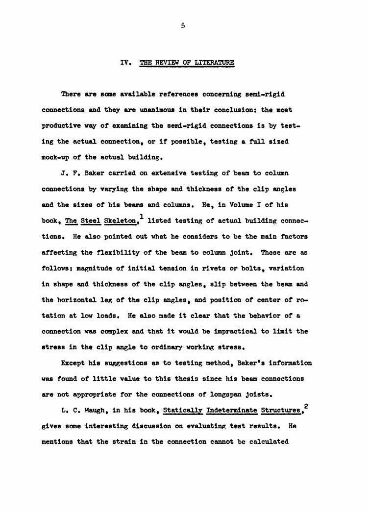
IV. THE REVIEW OF LITERATURE
There are Balle available references concerning semi-rigid
connections and they are unanimous in their conclusion: the most
productive va;y ot examining the a81li-rigid connections is by test-
ing the actual connection, or it possible, testing a f'ull sized
mock-up ot the actual building.
J. F. Bak.er carried on extensive testing of beam to column
connections by varying the shape and thickness ot the clip angles
and the sizes of his beams and columns. He, in Volume I of his 1 book, !2!. Steel Skeleton, listed testing of actuo.l building connec-
tions. He also pointed out what he considers to be the main factors
affecting the flexibility of the beam to column joint. These are as
tollowss magnitude ot initial tension in rivets or bolts, variation
in shape and thickness of the clip angles, slip between the beam and
the horizontal ler, ot the clip angles, and position of center of ro-
tation at low loads. He also made it clear that the behavior of a
connection was COlllplex and that it vould be impractical to limit the
stress in the clip angle to ordinary vorking stress.
Except his suggestions as to testing method, Baker's information
was found of little value to this thesis since his beam connections
are not appropriate for the connections of longspan joists.
L. c. Maugh, in his book, Statically Indeterminate Structures/
gives some interesting discussion on evaluating test results. He
mentions that the strain in the connection cannot be calculated
6
accurately as local stress concentration and def'ormation make the
problem too complicated. The essence or his advice on testing steel
connection is that it is difticult to evaluate the separate effects
of such individual factors as change in length of rivets, local bend-
ing or angles or tees, shearing deformation, and local bending of the
column flanges. Then be stated very clearly that the experimental
results for each particular type of connection can seldom be applied
to other types of connections. It ia the objective of this thesis to
provide for the partial testing of one type of connection.
John E. Lothers, in his book, Advanced Design !!!. Structural
Steei,3 has a chapter concerning design of semi-rigid connections.
The author found Lothers' approaching to analysis and design of aemi-
rigid connections to be very helptul 1 especially in understanding ot
the characteristic of' semi-rigid connections. Agfti.n, those connec-
tions are of different t;ypes than the one that vill be dealt vith in
this thesis.
Richard E. Welch, in his thesis, Semi-Risid Connections !! Trussed Beams, 4 tries to approach the design of semi-ri~~d connection
by mathematics 1 but finds thP. solution mathematically cumbersome, and
in need or laboratory veritication.
Lehigh University in conjunction vith the .Al!lerican Institute ot
Steel Construction has done rather e'Etensive testing on beam to column
connections and has developed tables and empirical equations expressing
rigidity and econorJ.cal value ot certain connections.5• 6 AISC itselt
has recognized certain type ot semi-rigid connections and even provides
7
examples as a guide to semi-rigid connection deaign.7 At the same
time, it enables the designer to take advantage of the potential
economy which is achieved by partial continuity in steel building
design. Here again, it is necessary to obtain data for each type
of connection by testing the actual connection.
Finally, Carlton E. C0111bs, Jr., in his thesis, ~ Ini·tial Stud.y
2!, Semi-Risid Connections Between LonGsran Joists~ Columna,8
developed a bolted connection of tee sections whose legs can slip in
the gaps between the bottom and top chord angles of longspan Joists
and be welded to them. Combs' teat result indicated that the connec-
tions were quite rigid and they behaved as rigid connections.
This thesis has carried on the idea or providing inrormation tor
a particular type or semi-rigid connection. By using the same long-
span joists and columns as Combs used, the author developed a new
type of semi-rigid connection which yielded satisfactory results as
obtained f'rom testing the t'ull size connection.
8
V. PROCEDURE
The objectiTe ot this investigation is to design a special
semi-rigid connection suitable for joining longspan joists and
columns, and to establish the behavior of thie particular group of
connections.
An one-stor,r • two-bq trame vaa chosen vi th typical dimensions
aa representative ot the use of semi-rigid connections of longspan
joists to columns. This particular trame was chosen for tvo reaaons.
First, it vaa to make this inwstiaation simpler since it vaa a sym-
metrical trame. Second, it was a framing pattern representative of a
great many canaon applications ot industrial longapan Joist traming.
There were tvo conditions of interest, They veres development
ot strength to resist wind forces and imprOYement of joist efficiency
through continuity prOTided by autticient end connectio119, Wind
strength is not provided by standard longspan joist construction
since the longspan joists are designed to be "simp~" supported on
maaonr,r bearing val.la, steel beama or columns, Thia type of con-
struction ia adequate tor aost wrtical loadings but lateral load-
ings, such as vind forces, cannot be austained by this poat and
lintel construction. 'l'heretore, lateral support or lateral stability
mwst come trom somevhere else in the building trame. In ccamon
practice tor this tn>e of building trames the lateral stability is
provided by he&'Vl' maaonr,r valla at appropriate intel"'Yala throughout
the entire building and transferred to individual bents through a
9
stiff roof deck, floor slab or from some system of trussing the
building frame work.
It is possible that a more economical and organic frame can be
realized when the posts and lintels are connected to make a coopera-
tive_frame. This cooperative frame will then be capable of resisting
both vertical and lateral loadings simultaneously. Immediately the
bearing masonry wall and trussing systems, or whatever supplied the
lateral support in the post and lintel system can be greatly reduced
or eliminated. It follows then, that the cost of fabricating and
erecting these frames may well be less than that of providing suf-
ficient lateral support in current longspan joist construction.
The second condition, improvement of joist efficiency through
continuity provided by sufficient end connections, is merely an
application of continuous construction principle to longspan joist
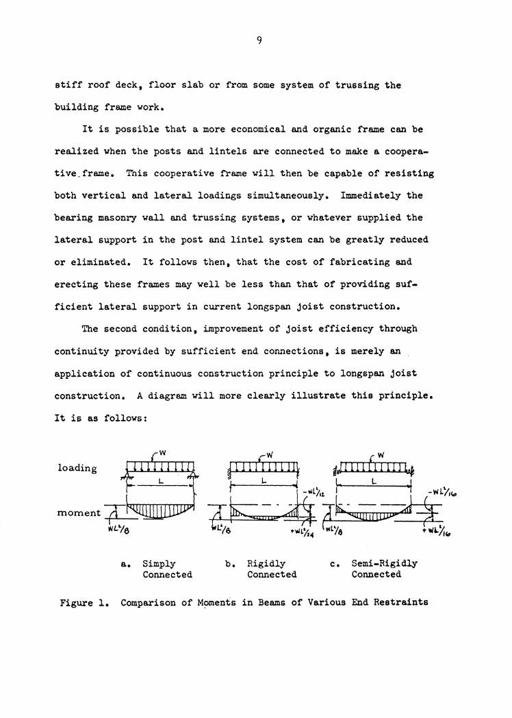
construction. A diagram will more clearly illustrate this principle.
It is as follows:
loading
a. Simply Connected
b. Rigidly Connected
c. Semi-Rigidly Connected
Figure l. Comparison of Moments in Beams of Various End Restraints
10
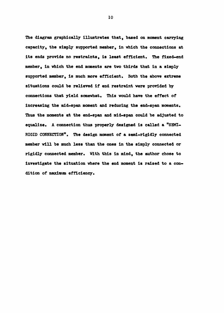
The diagram graphically illustrates that• baaed on moment carrying
capacity• the simpfy supported member• in vbich the connections at
its ends provide no restraints, is least efficient. The fixed-end
member, in vbich the end manents are two thirds that in a Bim.pfy
supported member, is much more etficient. Both the above extreme
situations could be relieved it end restraint vere provided by
connections that yield somewhat. This vould have the etf'ect ot
increasing the mid-span moment and reducing the end-span moments.
Thus the moments at the end-span and mid-1pan could be adjusted to
equalize. A connection thus properly designed is called a "SEMI-
RIGID CONNECTION". The design moment ot a semi-rigidly connected
member vill be much less than the ones in the simply connected or
rigidly connected member. With this in mind, the author chose to
investigate the situation vbere the end moment ia raised to a con-
dition of maximum efficiency.
11
VI. THE INVESTIGATION
The investigation is composed of two major parts, theoretical
and experimental. The theoretical part is the mathematical deter-
mination of the maximum negative moment capacity of the representative
Joists, the design of a semi-rigid connection to develop this negative
moment, and the calculation ot the rotation at the Joint due to the
behavior of the semi-rigid connections. The experimental part is the
laboratory procedure that vas followed, the data and results obtained
trom the four representative connections, plus a discussion and
conclusion from the tests.
A. THEORETICAL
1. Selection of Lonsspan Joists
The tour representative longspan joists were selected trom a
booklet which is published by Steel Joist Institute each year iden-
tifying the longspan Joists that are aTailable trom the members of
SJI.9 They are listed in Table l. There were aenral variables,
such as, Joist spans, Joist depths and joist weights, in selecting
the joists. In order to minimise the variables, the joists were
selected so that they might all haTe the same net load carrying
capacity. From the Joist characteristic table it can be seen that
they all have a net load c~ing capacity of approximately 330
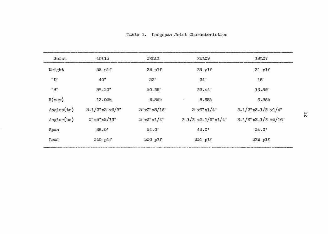
Table 1. Longspan Joist Characteristics
Joist 40113 32Lll 24L09 18107
Weight 36 plf' 29 plf 25 plf 21 pli'
nD" 4011 52" 24" 18"
!Id" 3s.:so11 30.29" 22.4411 16.591:
R(ma.x) 12.02k 9.59k 8.65k 6.88k
Angles(tc) 3--1/ 2" x3~: x3 / 811 ·s: x3'' xS/ 16" 3'' x3'' Xl/ 411 2-1/ 2" Y..2-1/ 2rr Xl/ 411 -N ft.ngles (be) 3" x3n "1-.5/16" 3:r x311 Xl./ 4t1 2--1/ 211 x2-l/211 xl/ 411 2-1/211 T..2·-1/211 x.3/16"
Span 68.0 1 54.01 43.0' 34.0'
Loarl 340 pli' 550 pl:f 331 pl.f 329 plf'
13
pounds per linear foot.
With the span corresponding to this net load, each joist has a
certain negative moment capacity. The correlation between the span
and the loading are: if the load is held constant, the development of
the negative moment capacity allows the span to increase or if the
span is held constant, the development of the negative moment capacity
allows the allowable load to increase. The author of this thesis has
chosen to hold the span constant and determine the increased load
carrying capacity of each joist. Then the maximum load of each joist
will be det.ermined. For this particular loading, there must exist a
proper semi-rigid connection that allows both positive and negative
moments to develop to optimum values simultaneously.
2. Description of Use of·Longspan Joists
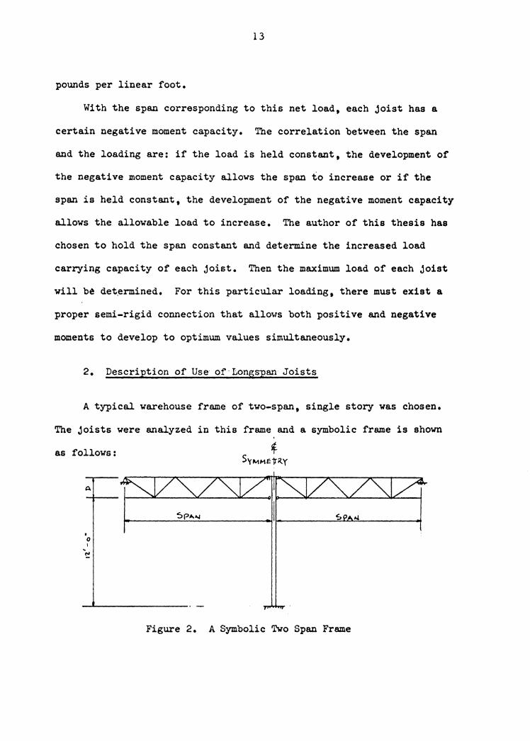
A typical warehouse frame of two-span, single story was chosen.
The joists were analyzed in this frame and a symbolic frame is shown
as follows:
I
0 I
~
Figure 2. A Symbolic Two Span Frame
14
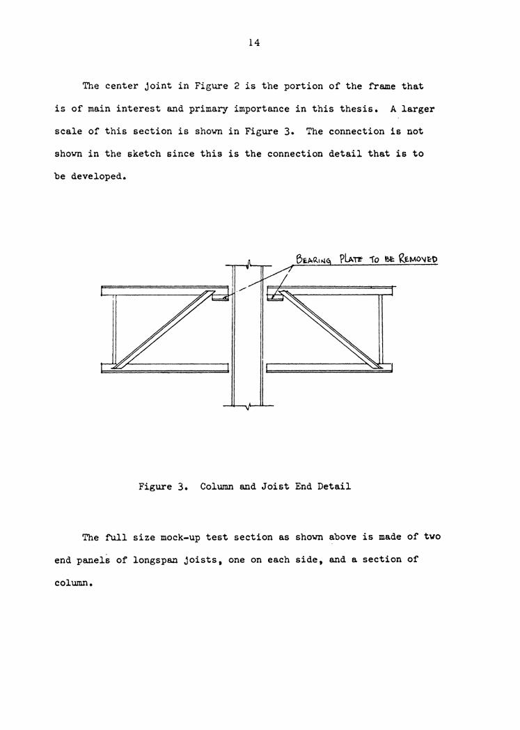
The center joint in Figure 2 is the portion of the frame that
is of main interest and primary importance in this thesis. A larger
scale of this section is shown in Figure 3. The connection is not
shown in the sketch since this is the connection detail that is to
be developed.
Figure 3. Column and Joist End Detail
The full size mock-up test section as shown above is made of two
end panels of longspan joists, one on each side, and a section of
column.
15
3. Characteristics ot Lol!lspan Joists
Section 103.l ot the 1959 edition ot SJI Standard Specification
ot Open Web Steel Joists states that steel joists shall be designed
as simply supported, unitorml.l' loaded trusses. Yet the author of this
thesis vill try to investigate later in this thesis the negatiTe
mcmlent capacity ot certain longspan joists.
There are some limitations vhich the joists, by their nature,
impose. First, the top chord ot Joists is assuned laterally sup.
ported along the entire length. This is usualq done by attaching
the floor slab or root deck to the top chord to stabilize and prevent
it fTom buckling. The bottom chorda are designed as axially loaded
tension members. It the connection is ao designed that it is stif'f'
enough to deYelop acne negative moment in the longapan joist then
there vill be a laterally unsupported length or the bottom chord of'
the truss in compression. The bottom chord then vill be able, to
some extent 1 to resist buckling 1 but this behavior must be kept in
mind.
A second limitation is that the members or a longspan Joist are
angles, rods and bars which are small in size cOlllpared to standard
structural beams and columns used in continuous framing. This means
that connections could be a problem because or their limited ability
to develop bearing under bolts or rivets.
There are also qualities which are desirable in the end connec-
tions. First, it is desirable tor the connection to act like a apring
16
which yields SOftlevhat to relieve the end restraint at Joints. The
spring o.ction ot a connection will cushion and reduce the degree or continuity at a rigidly framed joint or it will have the effect ot
modifying the moment diagram of a simply supported beam• thus show-
ing less positive moment at mid-span and more negative moment at the
ends. The joist will work more efficiently with the semi-rigid
connections since it will have a ne~ativa 111011ent while the positive
moment capacity of the joist remains unchanged.
Second• the connection should be one which can be easil.v
erected. This sug~ests the I>OB&ibility ot using construction bolts.
And third, it would be desirable if present longspan joist connec-
tions could be nodified simply and easily into semi-rigid connections.
17
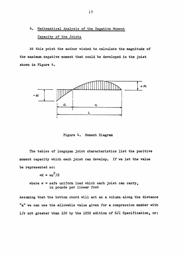
4. Mathematical Analysis of the Negative Moment
Canacitv of the Joists
.At this point the author wished to calculate the magnitude of
the maximum negative i:noment that could be developed in the Joist
shown in Figure 4.
+M
I
:I
Figure 4. Moment Diagram
The tables of longspan joist characteristics list the positive
moment capacity which each Joist can develop. If we let the value
be represented so:
+Mc wn2/8
where w = safe uniform load which each joist can carry, in pounds per linear foot
Assuming that the bottom chord will act as a column along the distance
"a" we can use the allowable value given for a compression member with
l/r not greater than 120 by the 1959 edition of SJI Specification, or:
18
r a 17,000 - o.~85 (l/r)2 c
in which "1" is the unsupported length and "r" is the corre-
sponding least radius of gyration or a member, both in inches.
By equating equation (F-l) with the dimensional relationships
of each Joist, we get the maximum negative moment capacity of each
joist as it is represented on the following pages.
19
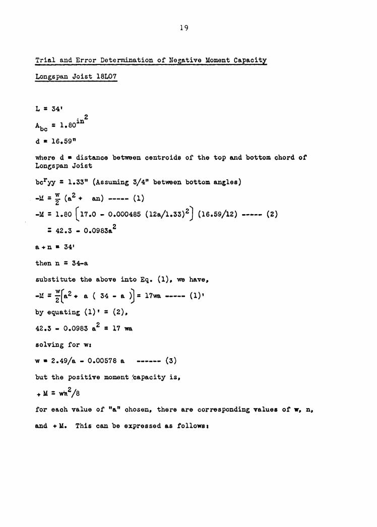
Trial and Error Determination of Negative Moment Capacity
Longspan Joist l8L07
L = 34' . 2
Abe = l.eoin
d • ls.59n
where d • distance between centroids or the top and bottom chord ot Lon~span Joist
bcryy = l.33" (Assuming 3/4" between bottom an,les)
-U = ; (a2 + an) (1)
-M: 1.80 (11.0 - 0.000485 (12a/l.33) 2J (16.59/12) ----- (2)
: 42.3 - 0.0983a.2
a+ n • 34'
then n = 34-a
substitute the above into Eq. (1), we have,
-M = ;(a2 + e. ( 34 - a. >J = 17wa ----- (l)'
by equatin' (l)' = (2),
42.3 - 0.0983 a2 = 17 11a
solving for wz
w • 2.49/a - 0.00578 a ------ (3)
but the positive moment ~apacity is,
+ M: vtn2/8
for ea.oh value of "e. n ohos en, there are corresponding values ot w, n,
and + 14. This can be expressed as follows z

20
2.49/a - 0.00578 a : w n _. M
4 0.623
5 0.498
6 0.416
0.0231
0.0289
0.0347
= 0.600 30+67.5
= 0.469 29+49.3
= 0.381 28+37.3
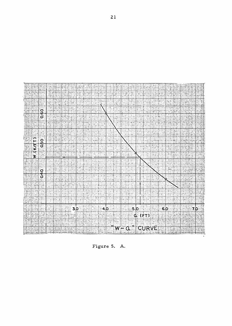
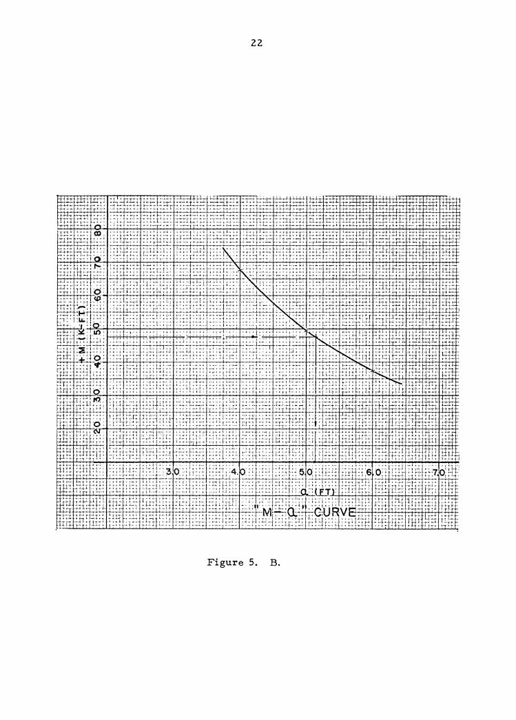
By the corresponding values of "a", "w" and "•M", two curves are drawn.
One is plotted on coordinates of ''a" and "w" and the other on ooordi.nates
of "a" and "<tM". They are designated a.s "w-a" curve and "+ M-a" curve
on following page.
From Table l \'9 have,
w • 0.329 kl.f
L = 34.0 i't
Consequently the maximum positive moment cape.city of the Longspan
Joist l8L07 can be obtained as .follows,
+M: 0.329 (34.0) 2/ 8 : 47.5 i't-k
By indicating this value on "+M-a" curve, we obtain a value of "a".
Then from "w-a" curve a corresponding value ot allowa.blo load is obtained.
It isa
a : 5.14
D : 34.0-5.14 • 28.86 f't
w = 0.455 klf
Consequently the maximum negative moment that the l8L07 oan carry is
caloulateda
1-xj .... (J
Q
~
11
Cl>
Ul . >
~t±tr:z~:T:titt-i?T!r!:!fr:~ l i
ii{
ff~S
F':i
ffir
ti:;
: :::
:-:l~.
J-:-r~
:i-fft
!li;~i
;-± t1
+L i-~Ht±±tI ~
~11-f
J:ti
~--ti-
h't
: ,--
rrt_~·
•ro-
r-t"
(-•.1
:1 --·-
,··-1
-'•r ·
·;_tf·
·L· +
t1"t
·h•
-:L•t·
•tn t-f
:crj-t
l;_;_
-,-+T
-•!U
tc _
,,J:
--,,-•
-;..
~Ei1~i
h fr0-
~!~ ~"
E!1~; i}
1i~~t_~~
{~ ~;~r
-'°itfr
~ti~
/~ t'.
;!~:i"t
1+~~itt~
~~ ~Ii
tl. ;nt ~
:;~fat
±5
1 •-
t:-
··t-+
-' i-•
••>---
•'"-J-
r••-
• .,It-•-••-~--,
··-'-•
-··-~~
---·r-
--i••
'•l·t:
•·•·
··-··
··-~-· -f
-C~
4H+ HU
T~Tf
FIT FHi
ntjITf
f~~~:o
:~tf-I
T f~Jf
fi~.5:
?ImF1f
~1tl?i
>~:i?~
f--TI1
-i~~~$
lill~ilr
,tlli~il
l.i1~1il
1;i~Jj
~t lliu~lf
J "Jf ~ fill1
1ii"t~ ·:'Jl;
;tl !l~~ 1 ~rm~ ·
ti]ill •~ ~·
q-rH
·'·-· ·--
;-,,.,c
. ···
·!'"' .,--
.-t---·
.... p
, ... ····
-1·----
.... t. .
..• -"
•1···
·· ::_~-y·-'·
--··-·S
·-· !1
~:rt
;!·! ~
-!r.
~!~~
: :f:
: ·!:.::
:i::·1:::
!2 :T:
:r;::: -
:.:: ~:
;~
:-:-:~
~:;-:~
· ::~
:·:1;f
1.-: .~/.l~!: :
_;~t
HiH
il~i"l
~lml1l
f liimi:~
l~rr~1
~1m1~1
rfitli
i~l1 il
j~ii 1r·l1
l.~:1 If I .f~
i~f J~1 i~i·t
1 ;~l11!!
~1t1
~.t+t
Jt;r ~
rt·.~w
·~:-:
:r.:i ~-
~!· ;-:
I:.t . .t
-~~r 7
-rr.~
-Et Fr..
!.:-~~
-.:-;·
;~ -:-
~T: 1:
;I ;;.4
rr-r~
i;.~t
:r!-f1-
-~~;-:
J-;~-~
1 t-t
tt_i.
•-,1:
-•l
rr·•
··-·
rt,-
i ,.,
.r •
.• ,,
-•r
··•
9:.,--:
;::·c,-
,_ '"'..::::!:--7•T~
,_t_
n_n
1-,-<
--•
•-•.
-h•-
.-.
·-n•·
~t.;:+
J .r
ttt ..
rrrr
·n-r
r t-r
. .
,
L •
.l..L.
.. -~
.:._;.
.. 47
~-.m
-J_ _
,;.__i._
L ::.r
r.:..:-.
. .;....i.~.
!... .!...
!'"W
.... ~i.
~ ~l.
.i. ~
..... .L-
.~ i. .
..... 1
. .1.
:L.:
1 r =
:
~-++
+-t
N
.......
22
Figure 5. B.
23
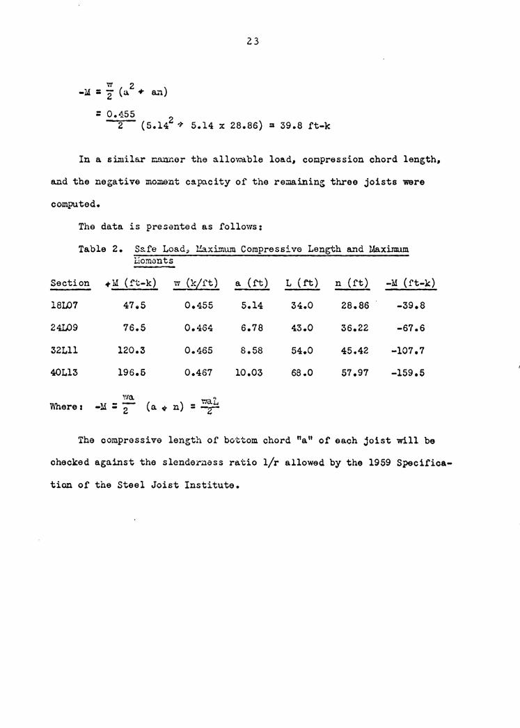
= 0.455 2 (5.142 ~ 5.14 x 28.86) = 39.8 ft-k
In a sL~ila.r ~er the allowable load, compression chord length,
and the negative moment capacity of the re;:naining three joists were
computed.
The data is presented as follows:
Table 2. Safe Load~ Maximum Compressive Length and Maximum l.:'iom0nts
Section +M (!'t-k) w CkLrt) a (ft) L (ft) n (rt) -M (rt-k)
18W7 47.5 0.455 5.14 34.0 28.86 -39.8
24L09 76.5 0.464 6.78 43.0 36.22 -67.6
32Lll 120.3 0.465 s.58 54.0 45.42 -107.7
40Ll3 196.6 0.467 10.03 68.0 57.97 -159.5
wa .. Wherez -M=2 (a-tn)=~
The oomprassive length of bo·ctom chord "a" of each joist will be
ohecked against the slende~uass ratio l/r allowed by the 1959 Specifica-
tion of the Steel Joist Institute.
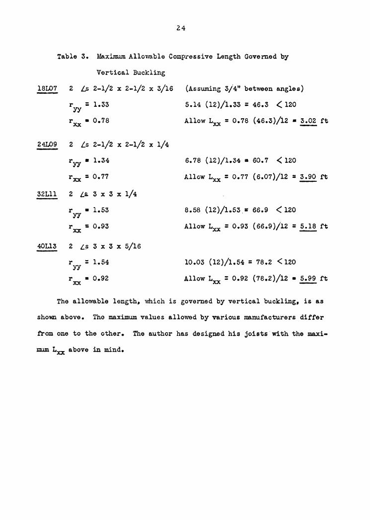
24
Table 3. Maxilm.un Allovra.ble Compressive Length Governed by
Vertical Buckling
l8L07 2 b 2-1/2 x 2-1/2 x 3/16 {Assuming 3/4" between angles)
r = 1.33 yy rxx • 0.78
24L09 2 Ls 2-1/2 x 2-1/2 x 1/4
ryy • 1.34
rxx = 0.77
32Lll 2 La 3 x 3 x 1/4
r • 1.53 Y1
rxx = o.93
40Ll3 2 L~ 3 x 3 x 5/16
r = 1.54 yy r • 0.92 xx
5.14 (12)/1.33 = 46.3 < 120
Allow Lxx = 0.78 (46.3)/12 • 3.02 ft
6.78 (12)/l.34 • 60.7 < 120
Allow Lxx = 0.77 (6.07)/12 = 3.90 ft
8.58 (12)/1.53.= 66.9 <120
Allow Lxx = 0.93 (66.9)/12 = 5.18 ft
10.03 (12)/1.54 : 78.2 < 120
Allow Lxx : 0.92 (78.2)/12 • ~ft
The allowable length. which is governed by vertical buckling. is as
shown above. Tho maximum values alloV1ed by various manufacturers differ
trom one to the other. The author has designed his joists.with the maxi-
mum Lxx above in mind.
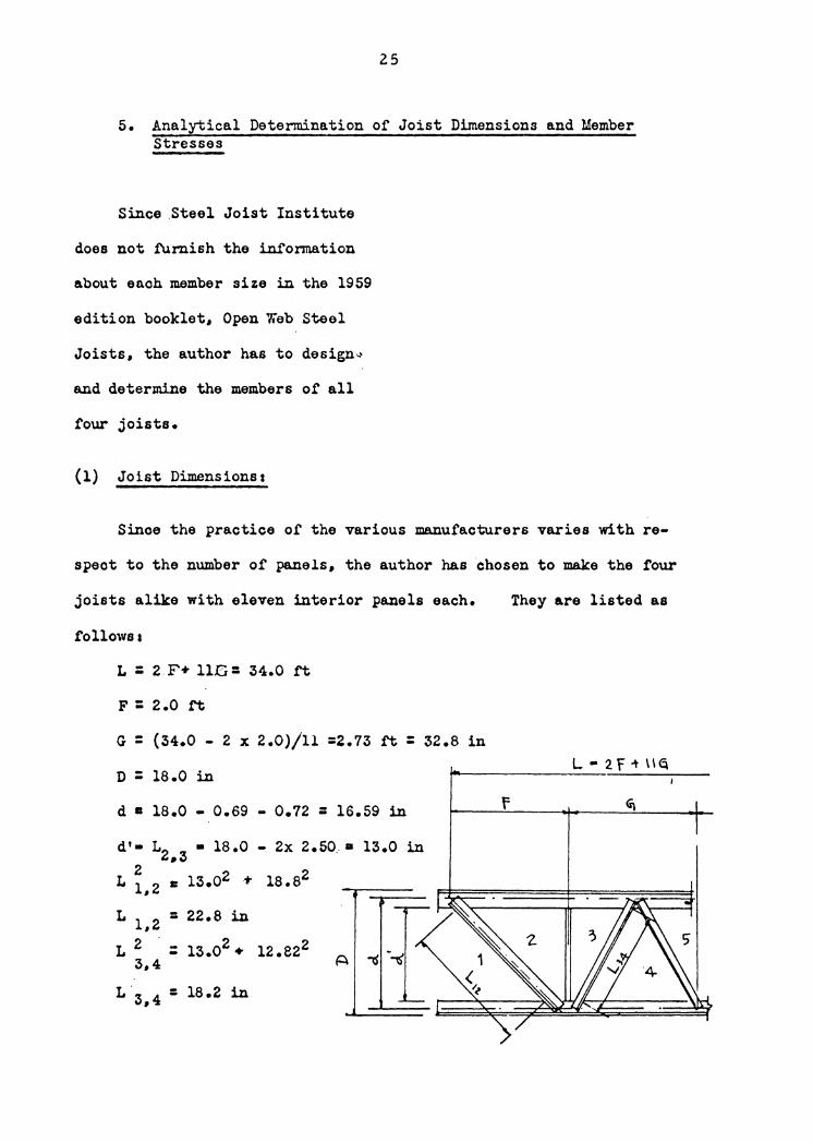
25
5. Analytical Determination or Joist Dimensions and Member Stresses
Since .Steel Joist Institute
does not furnish the information
about enoh member size in the 1959
edition booklet, Open Web Steel
Joists, the author has to design~
and determine the members of all
four joists.
(1) Joist Dimensionsa
Since the practice or the various manufacturers varies with re-
speot to the number or panels, the author has chosen to make the four
joists alike with eleven interior panels each. They are listed as
follows a
L : 2 F+ llG= 34.0 rt
F: 2.0 rt
G : (34.0 - 2 x 2.0)/ll =2.73 rt : 32.8 in
D : 18.0 in L • 2.f-t \lq
d a 18.0 - 0.69 - 0.72 : 16.59 in f
d'• L2, 3 • 18.0 - 2x 2.50.• 13.0 in
L 2 1: 13.02 ·t- 18.82 1,2
L 1,2 - 22.8 in -L 2 : 13.02 + 12.e22
3,4 A
L 3,4 = 18.2 in
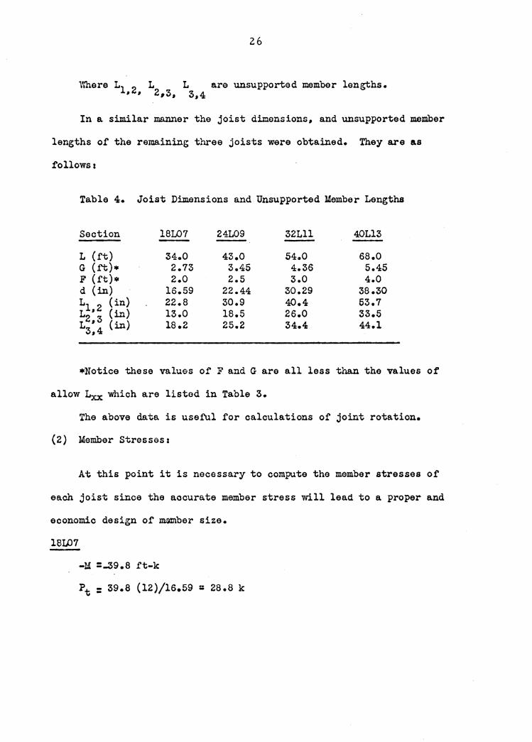
26
\\'here L1 2 L L are unsupported member lengths. , , 2,3, 3,4
In a similar manner the joist dimensions, and unsupported member
lengths of the remaining three joists were obtained. They are as
follows a
Table 4. Joist Dimensions and Unsupported Member Lengths
Section lSI..07 24L09 32Lll 40Ll3
L (ft) 34.0 43.0 54.0 68.0 G (ft)• 2.73 3.45 4.36 5.45 F (rt)• 2.0 2.5 3.0 4.0 d (in) 16.59 22.44 30.29 38.30 L1 2 (in) 22.8 30.9 40.4 53.7 L I (in) 13.0 18.5 26.0 33.5 1;:! (in) 18.2 25.2 34.4 44.l
•Notice these values of F and G are all less than the values of
allow Lxx which are listed in Table 3.
The above data is use.t'ul for calculations of joint rotation.
(2) Member Stresses:
At this point it is necessary to compute the member stresses of
each joist since the accurate member stress will lead to a proper and
economic design of JJWinber size.
18107
-M =-39.8 ft-k
pt = 39.8 (12)/16.59 = 28.8 k
27
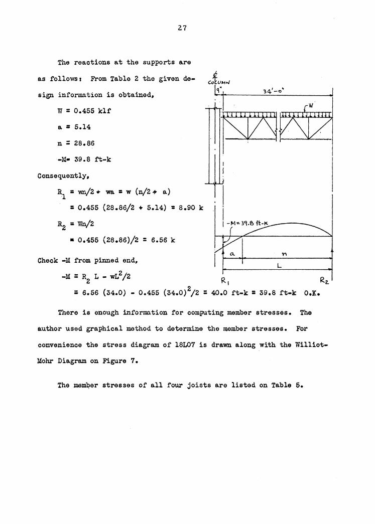
The reactions at the supports are
as tollowsa From Table 2 the given de-
sign information is obtained,
w = 0.455 klf
a = 5.14
n : 28.86
-M• 39.8 tt-k·
Consequently,
R1 = wn/2 * wa. = w (n/2 + a)
= o.455 (28.86/2 + s.14) = a.9o k
R2 : Wn/2
• 0.456 (28.86)/2 = 6.56 k
Check -M from pinned end,
. ·1
I I
I I -M'"'- 39.& ft.!( ------
L
-:M : R L - wL 2 /2 R R 2 1 z. : 6.56 (34.0) - 0.455 (34.0) 2/2 : 40.0 ft-k: 39.8 ft-k O.K.
There is enough information for computing member stresses. The
author used graphical method to determine the member stresses. For
convenience the stress diagram of 18L07 is drawn along with the Williot-
Mohr Diagram on Figure 7.
The maJJil:?er stresses of all four joists are listed on Table 5.
j
28
j K L N 0 p Q.
i<o t R"Ta. '11 ~
ra--"-r-i---~--~~~'~'q·~?~;~~~-~~-·~r-.-1 L ... '2. F + I\ g --·
Memb.
1-2 2-3 3-4 4-5 5-6 6-7 7-8 8-9 9-10
10-11 11-12 12-i3 13-14 l~-15
15-16 16-17 17-18 18-19 19-20 20-21 21-22 22-23 23-24 24-25 25-26 26-27
Stress. (kips)
14.8 -0.8
-10. 7 9.3
-9.3 7.7
-7.7 6.0
-6.0 4.2
-4.2 2.4
-2.4 0.8
.,.0.8 -0.9 0.9
-2.6 2.6
-4.4 4.4
-6.1 6.1
-7 .5 -0.8 10.4
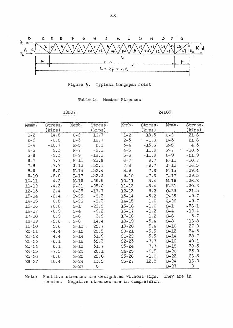
;Figure 6. Typical Longspan Joist
Table 5. Member Stresses
18L07 24L09
Memb.
C-2 D-3 E-5 F-7 G-9 H-11 J-13 K-15 L-17 · M-19 N-21 0-23 P-25 Q-26 S-1 S-4 S-6 S-8 S-10 S-12 S-14 S-16 S-18 S-20 S-22 s.:.24 S-27
Stress. (kips) 16.7 16.7
2.8 -9.1
-18.5 -25.6 -30.1 -32.4 -32.3 -29.9 -25.0 -17. 7 -8.3 -8.3
-28.8 -9.2 3.8
14.4 22.7 28.5 31. 9 32.3 31. 7 28.1 22.0 13.5
0
Memb.
1-2 2-3 3.:.4 4-5 5-6 6-7 7-8 8-9 9-10
10-11 11-12 12-13 13-14 14-15 15_;16 16-17 17-18 18-19 19-20 20-21 21-22 22-23 23-24 24-25 25-26 26-27
Stress. (kips)
18.3 -1.0
-13.6 11. 9
-11.9 9.7
-9.7 7.6
-7.6 5.4
-5.4 3.2
-3.2 1.0
-1.0 -1. 2 1. 2
-3.4 3.4
-5.5 5.5
-7.7 7.7
-9.3 -1.0 12.8
Memb.
C-2 D-3 E-5 F-7 G-9 H-11 J-13 K-15 L..;17 M-19 N-21 0-23 P-25 Q-26 S-1 S-4 S-6 S-8 S-10 S-12 S-14 S-16 S-18 s-2·0 'S-22 S-24 S-27
Stress. (kips) 21.6 21.6 4.3
-10.3 -21.9 -30.7 -36.5 -39.4 -39.3 -36.2 -30.2 -21.3 -9. 7 -9.7
-36.1 -12.4
. 3. 7 "16.8 27.0 34.3 38.7 40.l 38.5 33.9 26.5 16.0
0
Note: Positive stresses are designated without sign. They are in tension. Negative stresses are in compression.
29
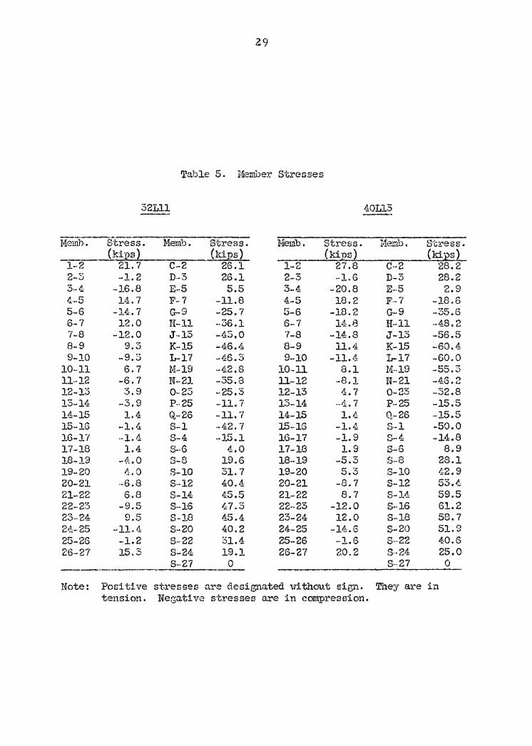
Table 5. Meni.ber Stresses
32Lll 40113
Meillh.-Stress. Meriib:- Stress. Memb. Stress. Me:m.b. Stress.
1-~ (kips~ (kips)
1-2 (kins} (ki:es)
21. 7 C-2 26.l 27.8 C·-2 28.2 2 ~· -..J -1.2 D.-3 26.l 2-3 -·1.6 D-3 28.2 3-4 -16.8 E-5 5.5 3-4 -20.8 E-·5 2.9 4-5 14.7 F-·7 -11.8 4-5 18.2 F ... 7 -18.6 5-6 -14.7 G-9 -25.7 5-6 -18.2 G-9 ·-35.6 6-7 12.0 H-11 --36.1 6-7 l-'.1:.8 H--11 --48. 2 7-8 -12.0 J .. 13 -45,0 '7-8 -14.8 J-13 -56.5 8-9 9.3 K--15 -•.1:6.4 8-9 11. 11 K-15 -60.4 9-10 -9.3 L-17 -L.J:6, 3 9-10 -11.4 L-17 -60.0
10-11 6.7 M-19 -42.8 10-ll 8.1 M-·19 -55.3 11-12 ~6.7 N-21 -35.8 11.-12 -8.1 N--21 -46.2 12-13 3.9 0-23 -25.3 12-13 4.7 0-23 -32.8 13-14 -3. 9 P--25 -11. 7 13-14 .. tl. 7 P--25 -15.5 14-15 1.4 Q···26 -11. 7 14-15 l.t!: Q-26 -15.5 15-16 -1.4 S-1 ·-42. 7 15--16 -1.4 S--1 -50.0 16-1'1 ·-1. 4 S-4 ·-15.1 16-17 -1.9 S-4 -14.8 17-18 1.4 S-·6 4.0 17-18 1.9 S-6 8.9 18-19 -<l:. 0 S-8 19.6 18--19 -·5.3 S-8 28.1 19-20 <:LO B-10 31. 7 19-20 5.3 S-10 42.9 20-21 ·-6.8 S--12 40.4 20-21 -8.7 S-12 53.4 21-22 6.8 S-14 45.5 21-22 8.7 S-14 59.5 22-23 -9.5 S-·16 47.'3 22--23 -12.0 S-·16 61.2 23--24 9.5 S-18 45.4 23-24 12.0 S-18 58.7 211-25 -11.4 S-20 40.2 24-25 -14.6 S-20 51.9 25-26 -1.2 S-22 31.4 25-26 M•l.6 S--22 40.6 26-27 15.3 S-24 19.l 26-27 20.2 S-·24 25.0
S-27 0 s-.21 0 ---.. Note: Positive stresses are designated 'd thout sign. They are in
tension. Negative stresses are in compression.

30
6. Design of Joist Members
The following design is based on the 1959 Specification of the
Steel Joist Institute and the 1956 Specification of the American Institute
of Steel Construction. Referring to Figure &, the joist members are de-
signated ass
Top chords a· C-2, D-3, E-5, F-7, etc.
Bottom chordsa S-1, S-4, S-6, S-8, etc.
Web membersa 1.2, 2-3, 3-4, 4-5, 5-6, etc.
The stresses are obtained from Table 5;. They are designated by
s1, 2 S S and so on, i.e., stresses in members 1-2, 2-3, 3-4, eto. 2,3 3,4 Again, the membe·r de sipi which will be illustrated as follows is covered
tor joist 18L07 onlyJ they area
(1) Top Chorda
2-Angles 2-1/2 11 x 2-1/2" x 1/4"
A : 2.38 in2
rxx • o.77 in
L = 2.727 ft = 32.73 in
Max. Stress at K-15, S = 32.4 k
F actual = 32.4/2.38 = 13.6 ksi
L/rrx. • 32.73/0.77 : 42.5 ( 120
£0 : 17,000 - 0.485 (L/rrx.) 2 : 17,000 - 0.485 (42.5)2
: 16 .13 ksi > t ·actual

31
Check the top chord for bending. (Section 103.4 (a) of the 1959 SJI
Specification)
(a) At Panel Point
sxx top = 2 (I/y) = 2 (0.10/0.12) • 1.95 in3
Sxx bottom= 2 (o.70/(2.5 - 0.72~ = 0.784 in~
M 11 o •. 455 (2.121) 2 (12)/12 = 3.4 in-k
f = 3.4/0.784 = 4.33 ksi b
L/rxx = 32.73/2(0.77) = 21.25
Fa = 16.78 ksi
fb/. • 13.6/16. 7.8 + 4.33/24.0 = 0.81 + 0.18 = 0.99 < l.O O.K. ~
(b) At .Mid-Panel 2
M: 0.455 (2.727) (12)/16 = 2.54 in-k
fb • 2.54/1.95 = 1.30 ksi
L/rxx • 32.73/o.77 = 42.5
F : 16.13 ksi a
fa/ + fb/ = 13.6/16.13 + 1.30/20.0 : 0.84 + 0.065 = 0.905 <1.0 O.K. . Fa. Fb
(2) Bottom Chordi
2-Angles 2-1/2 11 x 2-1/2 11 x 3/1&"
A = l.80 in2
rxx • 0.78 in
Max. Tensile Stress at S-16, S • 32.3 k
" . F aotual = 32.8/1.80 = 18.0 ksi <20.0 ksi o.K.
(3)
32
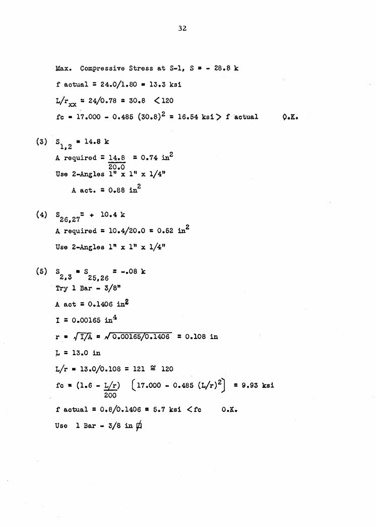
Max. Compressive Stress at S-1, S a - 28.8 k
f actual = 24.0/1.80 • 13.3 ksi
L/rxx = 24/0.78: 30.8 (120
fc • 17 .ooo - 0.485 (30.8) 2 = 16.54 ksi > f actual O.K.
S a 14.8 k 1,2
A required = ~ = 0.74 in2 20.0
Use 2-Angles 111 x 111 x 1/4"
A act. : 0.88 in2
(4) s26127= + 10.4 k
A required = 10.4/20.0 = 0.52 in2
Use 2-Angles l" x l" x l/4"
(5) s • s = -.08 k 2,3 25,26
Try 1 Bar - 3/8"
A act = 0.1406 in2
I : 0.00165 in4
r • {Ifi. a ,/ 0.00165/0.14.-06 = 0.108 in
;r. = 13.0 in
L/r • 13.0/0.108 : 121 ~ 120
fc a (1.6 - L/r) (11.000 - 0.485 (L/r) 2J = 9.93 ksi 200
tactual = 0.8/0.1406 = 5.7 ksi <tc O.K.
Use 1 Bar - 3/8 in ¢
(6)
33
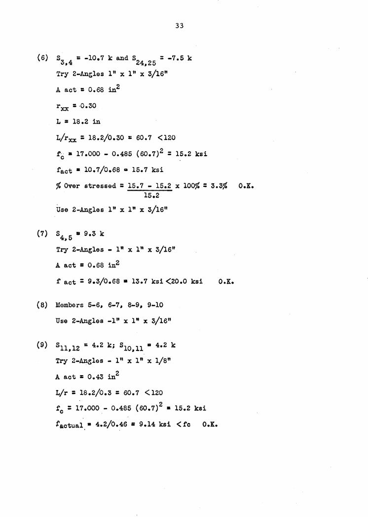
S = -10.7 k and S = -7.5 k 3,4 24,25 Try 2-Angles 111 x l" x 3/16"
A act = 0.68 in2
L = 18.2 in
t/rxx = 18.2/0.30 = 60.7 <120
fc a 17.000 - 0.485 (60.7)2 = 15.2 ksi
fact • 10.7/0.68 a 15.7 ksi
fo Over stressed : 15.7 - 15.2 x 100~ : 3.3~ O.K. 15.2
Use 2-Angles l '' x l" x 3/1611
(7) s4, 5 • 9.3 k
Try 2-Angles - l" x l" x 3/1611
A act = 0.68 in2
fact= 9.3/0.68 • 13.7 ksi<20.0 kai O.K.
(8) Members 5-6, 6-7, 8-9, 9-10
Use 2-Angles -1 1' x l" x 3/16"
(9) s11, 12 = 4.2 k; SlO,ll • 4.2 k
Try 2-An~les - l" x l" x 1/8"
A act = 0.43 in2
L/r = 18.2/0.3 : 60. 7 < 120
fc = 17.000 - 0.485 (60.7) 2 • 15.2 ksi
factual.• 4.2/0.46 = 9.14 ksi < fc O.K.
3.4
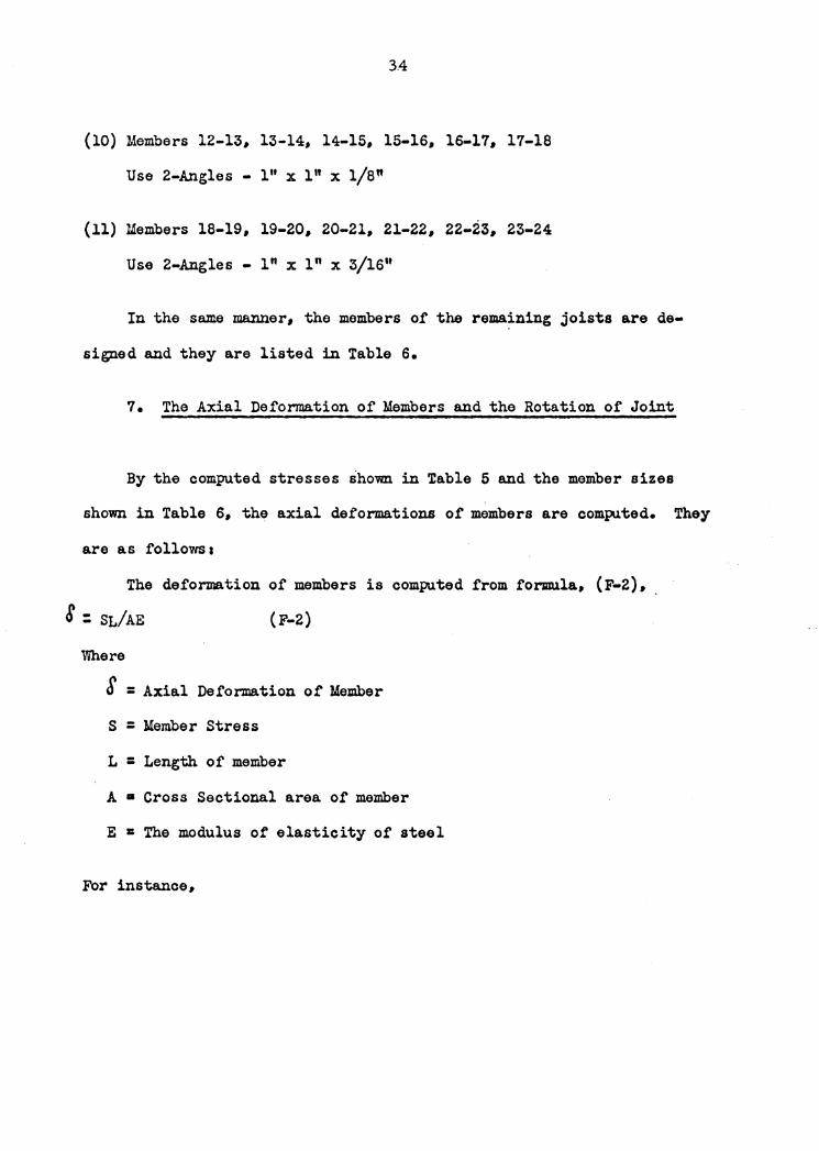
(10) Members 12-13, 13-14, 14-15, 15-16, 16-17, 17-18
Use 2-Angles - l" x l" x 1/8"
(11) Members 18-19, 19-20, 20-21, 21-22, 22-23, 23-24
Use 2-Angles - l" x 111 x 3/1611
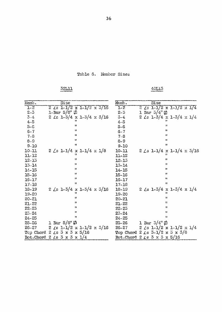
In the same manner, the members of the rema~ning joists are de-
signed and they are listed in Table 6.
7. The Axial Deformation of Members and the Rotation of Joint
By the computed stresses shown in ~able 5 and the member sizes
shown in Table 6, the axial deformations of members are computed. They
are as followsa
The deformation of members is computed from formula, (F-2), 8 : SL/AE (F-2)
Where
S = Axial Deformation of Member
S = Member Stress
L = Length of member
A • Cross Sectional area of member
E = The modulus of elasticity of steel
For instance,

35
Ta.ble G. M0:cr..be:c Sizes
18L07
Memb. Size -f-2~~-2,,_-L-s~-_,,_l_x__,l __ x~l-/-4--~-
2-5 1 Bru.· 3/811 r:/J 3-~ 2 Ls l x 1 x 3/16 4-5 II
5-·6 6-7 7-8 8-9 9-10
10-11 ll-12 12-13 13-14 14-15 15-16 16-17 17-18 16-19 19-20 20-21 21-22 22-23 2:-5-24: 24-25
11
II
II
II
a
2 Ls 1::;: 1 x 1/8 :t
" ii
II
II
II
2 Ls 1 x 1 x 3/16 II
II
II
II
II
II
25- 26 1 Bar 3 / B" r/J 26-27 2 Ls 1 x 1 x 1/4 Top Chord 2 Ls 2-1/2 x 2--1/2 x 1/4 _Bo_i:;_· ._C_h __ ord __ 2_L_s_2_-ll?_z._f._:]:/_?__?S_5j}-G
24109
MCffii):--------- Size ,. __ _
1-2 2 LG 1-1/2 X 1-l/2):3!".i6 2-3 1 Bar 1/211 r/J 3-4 2 Ls 1-1/2 x 1--1/2 x 3/16 4-5 " 5-6 II
6-7 7-8 8-9 9-10
10-11 11-12 12-15 13--14 14: .. 15 15-16 16--17 17-18 18-19 19-20 20 .. 21 21-22 22-23 23-24 24--25 25-26 26-27 Top Chord Bot.Chord
II
11
1!
2 Ln 1 x 1 x 3/16 11
II
If
II
II
II
2 Ls 1-1/2 x 1-1/2 x 5/16 " II
II
ti
II
l Ba.r 1/ 2" r/J 2 Ls 1-1/2 x 1--1/2 x 3/16 2 Ls 3 x 3 x 1/4 2 Ls 2-1/2 x 2-1/2 x 1/4
Memo. 1-2 2·-3 3 . .1J: 4 .. 5 5-6 6-7 7-8 8-9 9 .. ].Q
10··11 11--12 12--13 13--14 l-i-15 l5-16 16-17 17·-18 18-19 19-20 20-21 21-22 22-23 23-24 24-25 25-26 2G--27 Top Chord Dot.Chord
36
Table 6. Mem1')er Sizes
32Lll
size 2 Ls 1-·lf'l-x-· '"""'1-...._,,1_,/"'""2_x __ """3/~1'"""6 1-Bar 5/8" r/J 2 Lr. 1-3/4 x 1-·3/4 x 5/16
II
II
II
II
II
II
2 Ls 1-1/4 x 1-1/4 x 1/8 ii
II
" If
II
II
2 Ls 1-3/4 x 1-3/4 x 3/16 II
II
II
" " "
1 Bar 5/811 ltl 2 Ls 1-1/2 x 1-1/2 x 3/16 2 LS 3 x 3 X 5/16 2 Ls 3 x 3 x 1/4
Memb. 1-2-2-5 3-4 4 .. 5 5-6 6-7 7--8 8-9 9-10
10-11 11-12 12-13 13-14 14-15
40Ll3
Size 2 Ls 1-1/2 x 1~1/2 x 1/4 l Bar 5/ 411 r/J 2 Ls 1-3/4 x 1·-3/4 x 1/4
II
II
II
" II
II
2 Ls 1-1/4 x 1-1/4 x 3/16 II
" II
II
15-16 II
16-17 II
17-18 II
18-19 2 Ls 1-5/4 ::c 1-3/4 x 1/4 19-20 II
20-21 II
21-22 r: 22-23 II
23-24 tr
24-25 II
25 •. 26 1 Bar 3 / 4" r/J 26-27 2 Ls 1-1/2 x 1--1/2 :it 1/4 Top Chord 2 Ls S-1/2 x 5 x 3/8 Bot.Chord 2 Le 3 x 5 x 5/16
37
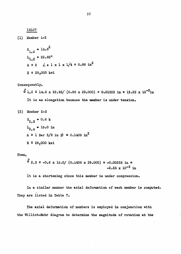
18L07
( l) Member l-2
K s1,i • 14.8
L1, 2 : 22.85"
A = 2 Ls l x l x 1/4 = o.aa in2
E : 29,000 ksi
Cons.equently,
S l,2 : 14.8 x 22.85/ (0.88 x 29.ooo) = ·0.01325 in = 13.25 x lo-3in
It is an elongation because the member is under tension.
( 2) Member 2-3
Then,
s2, 3 II 0.8 k
L2 ,~ • 13.0 in
A = l Bar 3/8 in \ti = 0.1406 in2
E = 29,0.00 ksi
8 2,s = -o.a x 13.0/ (0.1406 x 29.000) = -0.00255 in = -2.s5 x io-3 in
It is a shortening since this member is under compression.
In a similar manner the axial deformation of each member is computed • .
They are listed in Table 7.
The a.xial deformation of members is employed in conjunction with
the Williot-Mohr diagram to determine the magnitude of rotation at the
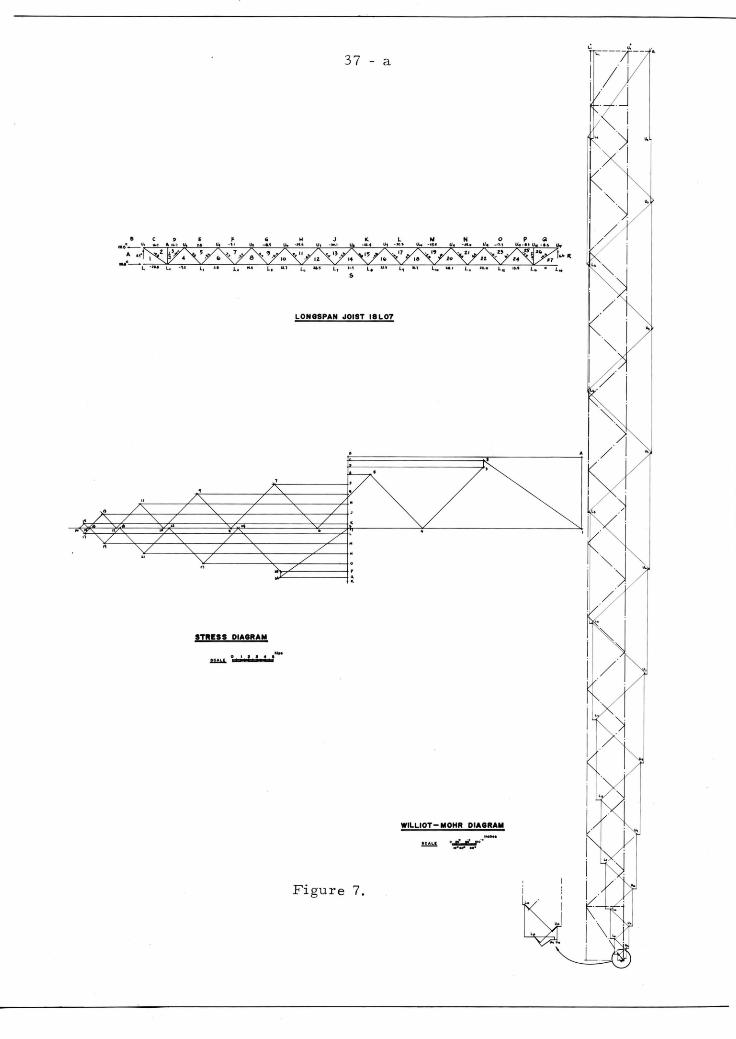
STRESS DIAGRAM
.... .wJ.J.01!!4!
37 - a
LONGSPAN JOIST 18L07
Figure 7.
WILLIOT-MOHR DIAGRAM
0 ;:.t'.,r·· .......
rl _/ : . I ""'· .
I ~/
..
38
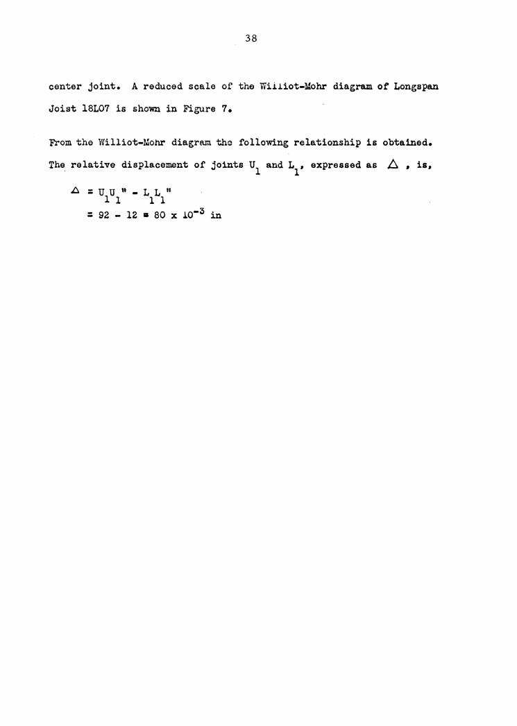
center joint. A reduced scale of the Wiiiiot-Mohr diagram of Longapan
Joist l8L07 is shown in Figure 7.
From the Williot-Mohr diagram the following relationship is obtained.
The relative displacement of joints u1 and L1, expressed as ~ • is.
1:::. =uu"-LL" 1 l 1 1
= 92 - 12 • ao x io-3 in
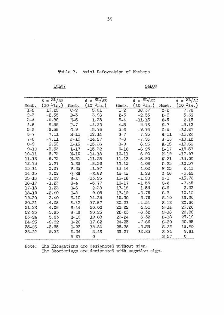
39
'l'ah1e 7. A .. 'tla.1 D~f' 01''".m.a.t:!. on o·:=> ,_ :M:ember·s
10L07 24L09 -·- ----· ~L· -~ 6 = SL/,~E 6 = SL/AE 6 = 0 (P.;B 6 = ..,L/ .r-JJ
Memb. (10-?i11.) Me..mb __ • _ ( 1Q-3:i.1.!:..)_ M~ab. _i io-·3in. ) II!~_( l0-·3in_J_ --1--2 1:5.25 C-2 5.8]. 1-2 18.37 C--2 7.76
2-S -2.55 D-3 ... 0"' .'.). vO 2-3 -2.55 n .. :3 5.3G
5 .. 4 -~}. 88 }J-5 l.Z53 3 .. 4 ·-11.15 E-5 2.13 1--5 8.58 f'- 7 ~ ';''J ,....£...;. ·~)~ 4-5 9.76 F·-7 --5.12 5 .. () -8.513 G-9 -8. 78 5 .. 5 -·9. 7G Q .. 9 ~10.87
G-· 7 7.11 H-11 --12.14 G- '7 7.95 H-11 ·-15 .2.:.!, 7-8 -7.11 J-·13 -1-1. 27 7-8 ... 7.95 J-13 -18.12 8-9 t- ..... ..,
~.o.'.J K--15 -15. ~j6 8-9 6 ..,~, .,_,~ K-15 -19.5G
9 .. :w -5.53 L-1? -15. ~52 9--10 .. 5. 2:) L-17 -19.57 10-·11 5.73 M-19 -14.18 10-11 6.90 M--19 -·17. 97 ll·-12 .. 5. 73 N-21 -11.35 11-12 -6.90 U-·21 -15.00 12-1::5 S.27 0-23 -8.39 12--15 4.08 0-2Z5 -10.57 13·-14 --3.27 P-25 --1. 97 1:3.-14 -·Ll. 08 P--25 .. 2. -11 14.:-·15 J..09 Q-26 -·2.89 14--15 1.28 Q-26 -3.48 15--16 -1.09 S-1 --13. 23 15-lG -1.28 S-1 -15. ?O lG-17 --1. 23 S--4 -5.77 16-17 ··1.53 S--4 -7.45 17-18 1.23 S-6 2. ~:i8 17--18 l.53 S-6 2.22 18-19 -2.40 S-8 9.03 J.3-19 -2.79 8-8 10.10 19-20 2.40 S-10 11.25 19-20 2.79 8-10 16.20 20-21 -·1.0S 8-12 17.87 20--21 -'1:. 51 S-12 20.60 2J.--22 4.06 S--1-1 20.00 21-22 4.51 S-14 23.20 22-23 --5.63 S-16 20.25 22 .. 25 -·G.32 S-lG 21.J, .06 23 .. 24 5.63 S--18 19.80 23-24 G.32 S-113 23.10 24-·25 -G.82 S--20 17.62 2tl-25 - '7. 63 S--20 20.35 25-20 -2.55 3 .. 22 13.80 25-26 -·2.55 8--22 15.80 26--27 9.32 S-24 8 .. 113 26--27 12.85 S-24 9.61
S--27 0 8-27 0
Ilfo·Ge; The Elcn~;ations a.re designated ·wj_tl1cut ::;ign. The ShorteningG arc: dcsigrn:i.:t;ed with negative sig:.r1.
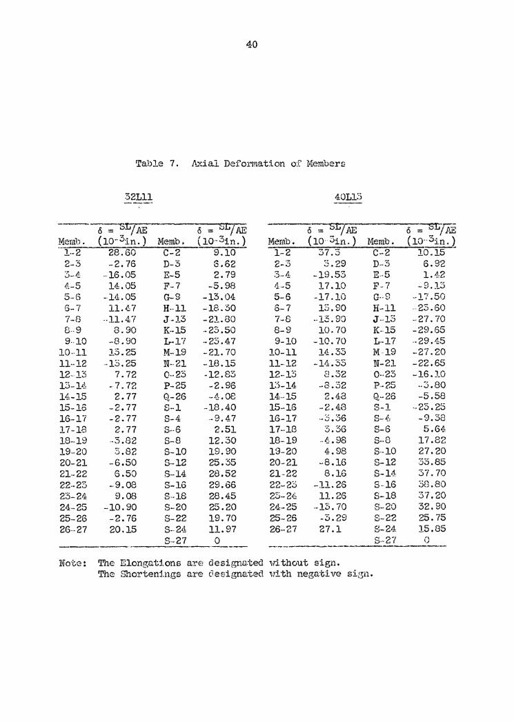
40
Table 7. J\.xial Deformation of Members
32Lll 40Ll:-:i ---· ---
--- cS = -SL I AF, cS = sr;; A'E cS = --sr;/Af?, cS ~{ii, ~ern.b. ( l0··31n. ) Memb. ( l0-3in.) Memb. (10· 3in.) Memb. (10--3in.1
1--2 28.60 C-2 9.10 1-2 37.3 C-2 10.15 2-3 -2.76 D-3 6.62 2-3 3.29 D--3 6.92 3-4 ···16.05 E-5 2.79 .).-4 -19.53 E--5 1.42 ~t-5 14.05 F-7 -5.98 4-5 17.10 F-7 -9.13 5-G -·14.05 G-9 -13.04 5-6 -17.10 G-·8 -17 .50 6-7 11.~7 H--11 -18.30 6-7 13.90 H-11 .. 23 .60 7-8 --11.47 J--13 -21.80 7--8 ·-13. 90 J--1~) --27.70 8--9 8. 90 K--15 -23.50 8-9 10.70 K-15 -2~). 65 9 .. 10 -·8. 90 L--17 ·-23.4 7 9-10 -10. 70 L--17 ·-29.4:5
10-·ll 13.25 M--19 -21. 70 10-11 14.33 M--19 --27. 20 11--12 -13.25 N--21 -18.15 11--12 -14.33 N-21 -22.65 12-13 7. 72 0--23 -12.83 12--13 8.32 0--23 -16.10 13-H, - 7. 72 P-25 -2.96 1:5-14 -8.32 P--25 --3.80 14-15 2.77 Q-26 ... 1, 08 14--15 2.48 Q,--26 -5.58 15-16 -2. 77 S-1 -18.40 15-16 -2.48 S-1 .. 23. 25 16-l'i -2. 77 S-4 --9. 4 7 lG-17 ... ~.36 8-·~: -9.38 17-18 2. 77 S--6 2.51 17--18 3.3G S-6 5.G4 18--19 --3. 82 S-8 12.30 18-19 .• .12:, 98 S--8 17 .82 19--20 3.82 S-10 19.90 19-20 4.98 S--10 27.20 20-21 -6.50 S-12 25.35 20-21 -8.16 S-12 33.85 21--22 6.50 S--14 28.52 21-22 8.lG S-14 37.70 22 .. 23 --9.08 S-16 29.66 22-20 -11. 26 S--16 38.80 23-24 9.08 S--18 28.45 23--2L}: 11.26 S-18 3'7.20 24-25 -10.90 S-20 25.20 2t1-25 --13. 70 S--20 32.90 25-26 -2. 76 S-22 19.70 25--26 -3.29 S-22 25. 75 26--27 20.15 S--2'1 11.97 26--27 27.l S-24 15.85
S--27 0 s ... 27 0 ·-------- -----------Note: The ElongaMons arE: des i gna.ted without sign.
The Shorten:l.ngs are c.lesignatec1 ili"th negrd:.ive si::511.

41
Consequently, the rotation at the restrained end ot the joist is,
+ • A/d
• 0.080/16.59 c 0.0048 rad.
In a similar manner the rotation at the restrained end or the
remaining three joists are obtained. They are as tollovaa
Table 8. Displacement and Rotation at the Restrained Joint
Section 18L07 24L09 32Lll 40L13
" ( -3 ) u1 u1 10 in. 92 116 151 195
t 1 Li" (lo-3 in.) 12 26 Ji5 45
A (10-3 in.) 80 90 106 150
d (in.) 16.59 22.44 30.29 38.30
+ (radians) 0.0048 o.oo4o 0.0035 0.0039
8. Ana).yais and Design of Semi-Rigid Connection
Before discussing the design or semi-rigid connection, it is
necessary to have a definition ot the term, semi-rigid connection.
It the beam-column connections or a building frame transmits bending
moment without relative rotation between the end or the beam and the
column, the connection and the structure are termed "rigid" (Fig. lb).
In such a caae, the connections affords 100 per cent restraint or tull
continuity, and the maximum bending momenta are at the ends or the
beam. It the connections transmits bending moment with some relative

42
rotation between the end of the beam and the column, the connections
and the structure are termed "semi-rigid" (Fig. le). In such a
structure, the connections resist bending moment to some degree less
than in the case of full continuity, and the moment in the center of
the span is always less than if the connection afforded no restraint,
as in a simply supported beam (Fig. la). 5 Now that the negative
moment capacity and joint rotation of each joist are known, an attempt
can be made to design a semi-rigid connection to develop this negative
moment and joint rotation in the joists.
The author of this thesis began his connection design with the
connection which Combs suggested in his thesis,8 after his experi-
mental results failed to indicate the characteristics of semi-rigid
connections (Figure 8). After some thought this form of connection
was discarded because of the difficulty of determining the deforma-
tions of the bolts involved.
Figure 8. Preliminary Proposed Connection Detail
43
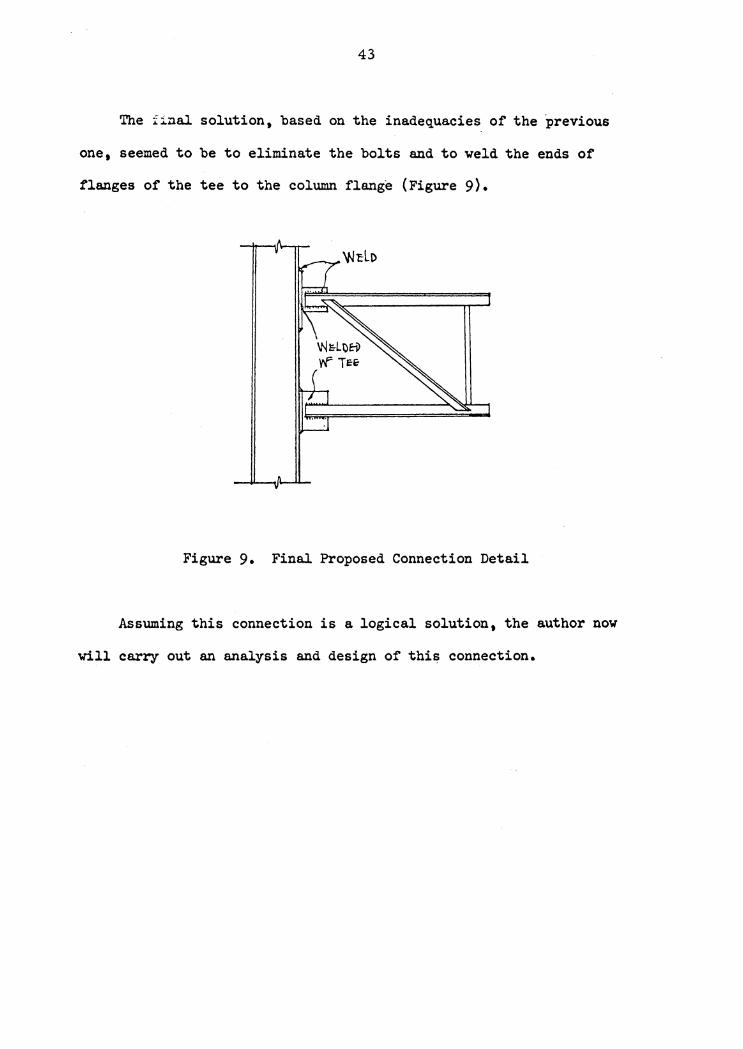
The final solution, based on the inadequacies of the previous
one 9 seemed to be to eliminate the bolts and to weld the ends of
flanges of the tee to the column flange (Figure 9).
Figure 9. Final Proposed Connection Detail
Assuming this connection is a logical solution, the author now
will carry out an analysis and design of this connection.
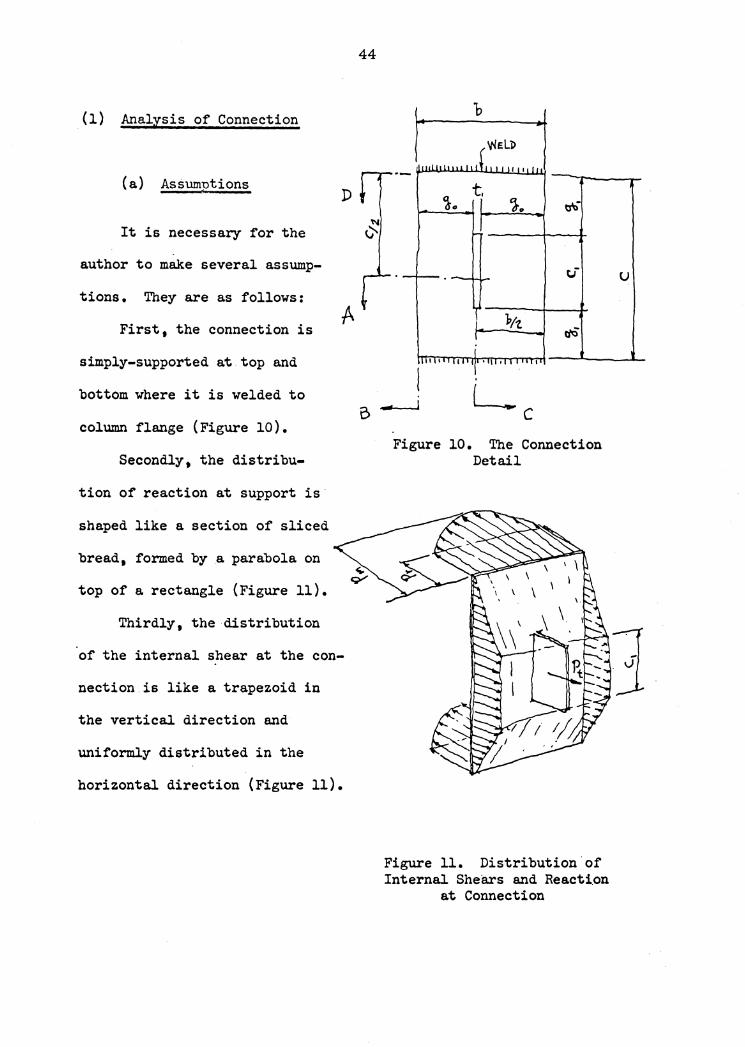
(1) Analysis of Connection
(a} Assunmtions D
It is necessary for the
author to make several assump-
tions. They are as follows:
First, the connection is
simply-supported at top and
bottom where it is welded to
column flange (Figure 10).
Secondly, the distribu-
tion of reaction at support is
shaped like a section of sliced
bread, formed by a parabola on
top of a rectangle (Figure 11}.
Thirdly, the distribution
of the internal shear at the con-
nection is like a trapezoid in
the vertical direction and
uniformly distributed in the
horizontal direction (Figure 11).
44
b
t '!o
i:.r
"P/t
B ----1
Figure 10. The Connection Detail
Figure 11. Distribution of Internal Shears and Reacti.on
at Connection
u

45
Section A. Section B.
,/ ... -.......... /, r-..11'1 / -~
Section C. Section D.
Figure 12. Sections of Connection
46
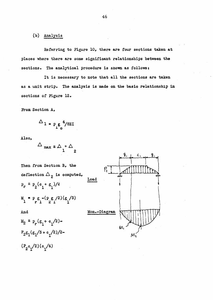
(b) Analysis
Referring to Figure 10, there are four sections taken at
places where there are some significant relationships between the
sections. The analytical procedure is shown as follows1
It is necessary to note that all the sections are taken
as a unit strip. The analysis is made on the basio relationship in
sections of Figure 12.
From Section A,
Also,
bi, 1 • p g 4/8EI .1. 0
Then from Section B, the
deflection ~ 2 is computed,
p = p (c + g )/i r 2 1 . 1
M a p g -(p g /2)(g /3) l r l i .1. l
And
lL : p ( g + c /2 )---.:! r l l
P2g1 (g1/3 + c1/2}/2-
(P c /2) (c /4) 2 l 1
Load
\ Mom.-Diagram
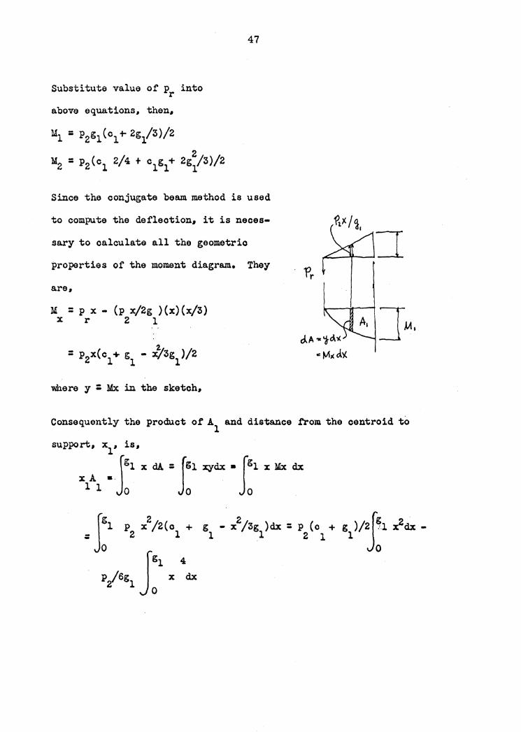
Substitute value of p into r
above equations. then.
47
Since the conjugate beam method is used
to compute the deflection. it is neces-
sary to calculate all the geometric
properties of the moment diagram. They
a.re.
M = p x - (p x/2g )(x)(x/3) x r 2 1
2. = p2x(c + g - x/3g )/2 l 1 l
where y : Mx in the sketch.
. 1'r
Consequently the product ot A1 and distance .t'rom the centroid to
support. x1• is,
Jgl x dA = Jgl xydx • Jgl x Mx dx x A •·
l 1 0 . 0 0
jg 2 2 l p x /2 ( c + g - x /3g ) dx = p ( c + = 2 l l .1 2 l 0 Jgl 4
P/6g1 O x dx

48
= p (c + g )/2 \x3/3 lgl - p /6g 2 1 1 2 l
0
s p2g (c + 4g /5)/6 l l l
The area A2 is expressed as.
A : c M /2 : pg c (c + 2g./3)/4 2 1 l 2 l l l l
x2 • g + c /4 l l
And the area A~ is a segment of a parabola. because the load at
this portion is uniformly d,istributed.
M - M = p ( 0 2 I 4 + c g + 2g 2 /3) /2 2 1 2 l l l l
- p g ( c + 2g /3) /2 2 l 1 1
= p c 2/8 2 l
A : (2/3)(M -M )(c /2) : pc 3/ 24 3 2 l l 2 l
X3 :: gl + d ia g t 5 . C /l 6 . l l
Then the deflection. Di. • is, 2
A : (A x + A X +- A x ) /EI 2 l l 2 2 . 3 3
M,
:rp g 3(o + 4g /5)/6 + (pg c /4)(o + 2g /3)(g + o /4) ~2 l 1 l 2 l l 1 l 1 1 ..

49
+ (p o 3/24)(g + 5 c /ls)J /EI 2 1 1 1 .
: p (4g 4/s + 2 g 3o + 7g 2o 2/4 +. Sg o 3/a 2 l 1 l 1 1 l 1
+ Sc14/64) /6EI
Let k :: 4g 4/s + 2g 3o + 7g 2c 2/4 + 5g o 3 /~ + 5 c 4/64 0 1 l l 1 l l 1 l
D. - p k /6 EI 2 - 2 0
Consequently the relationship as follows is true,
~ :: ~ + max 1
= p g 4/SEI + p k /6EI 1 0 2 0
~ = p (g 4/4 + k /3) /2EI --------------------------------(A) max 2 0 O
From Section C, Figure 12,
~ • p g 3 /3EI - · g 3 ( p g /2) /l5EI max mi 1 21
: g 3(p - p g /10)/3EI --------------------------------(B) 1 m 2 1
Subs~itute (A) into (B), collect terms and simplify, ·
p2(g04/4 + k /3)/2EI : g 3(p - p g /10)/EI 0 1 m 2 1
p2 = 40 p g 3/ (15 g 4 + 20 k + 4 g 4) m l · O O l
=40pg3/k m l 1

50
where k = l5g 4 + 20k t 4g 4 1 0 0 l
substitute the value p2 into Equation (B),
.6 ::; g 3 p ( 4g 4 + k ) I 3EI k ------------------------(B-1) max l m l l i
.from Section B, Figure 11,
p = p (c + g ) /2 r 2 1 1
again substitute value of p2 into above equation,
pr : 20 p g 3 (c + g ) /k -------------------------------(0) m 1 1 l 1
from Figure 11, the total reaction, V, at support is,
v = p /2 ~ p b t 2 (p - p ) b/3 t r m r' t'I,... ~ ~· I~
I'. I
p = 3 p /4b - p /2 "' m t r \
substitute Eq. (C) into above equation,
3 p 111 3p /4b - 20 p g (c + g )/2 k m t m 1 l l 1
Collect terms,
3 4 p G 3 p k /4b (k + 10 g c + 10 g ) ------------------(D) m t l l 1 1 l
substituting Eq. (D) into Eq. (B-1), the maximum deflection is obtained,
3 4 f:::. = g p ( 4 g + k ) /3Eik max l m 1 l l
= 3g 3p k (4g 4 + k )/4b (k + lOg 3c + lOg 4 )(3Eik) .1 t l l l l l l 1 1
51
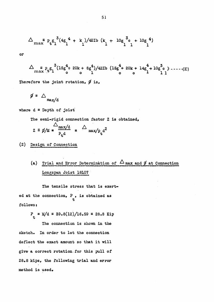
6 max= Ptg13(4g14 + k )/4Eib (k + lOg 3c + lOg 4)
1 1 1 1 l
or
Therefore the joint rotation, ¢ is,
¢= 6 max/d
where d = Depth of joist
The semi-rigid connection factor Z is obtained, 6
Z : ¢/M i: maxf d = A max/p d2 Ptd t
(2) Design of Connection
(a) Trial and Error Determination of 6 max and fl at Connection
Longspan Joist 18L07 ·
The tensile stress that is exert-
ed at the connection, P , is obtained as t
follows a
P = M/d : 39.8(12)/16.59 : 28.8 Kip t
The connection is shown in the
sketch. In order to let the connection
deflect the exact amount so that it will
give· a correct rotation.for this pull of
28.8 kips, the following trial ·and error
method is used.

0 = 16.5 in.
min. c • 5.0 in. l
52
mv.x. g = ~ (16.5-5.0) = 5.75 in. l
g = 3.717 in. 0
(i) if g = 2.0 in. 1
then o • 16.5 - 2 x 2.0 : 12.5 in. l
and k = 4 r//5+2 g3c. + 7g2c 2 /4 + 5g /J /a +504/64 0 l 1 1 l l l 1 l
= 5. 655.0 in4 .
Eq. (E) b:. max = P g3 (15g4 t 20k + 8g4 ) t 1 0 0 1
where b : 8.117 in.
E : 29.000 ksi
I = bt3/12 : lx0.6833/12 : 0.0265 in4
consequently.
: 0.244P /EI t
b. ~·: rna.x/d = 0.244 ~t/Eid = 0.55 x io-3 rad
Z : ~/M = ~ max/Ptd2 ::(0.244Pt/EI)(l/:£\d2 )
= o.244/Eid2 = 0.115 x io-5
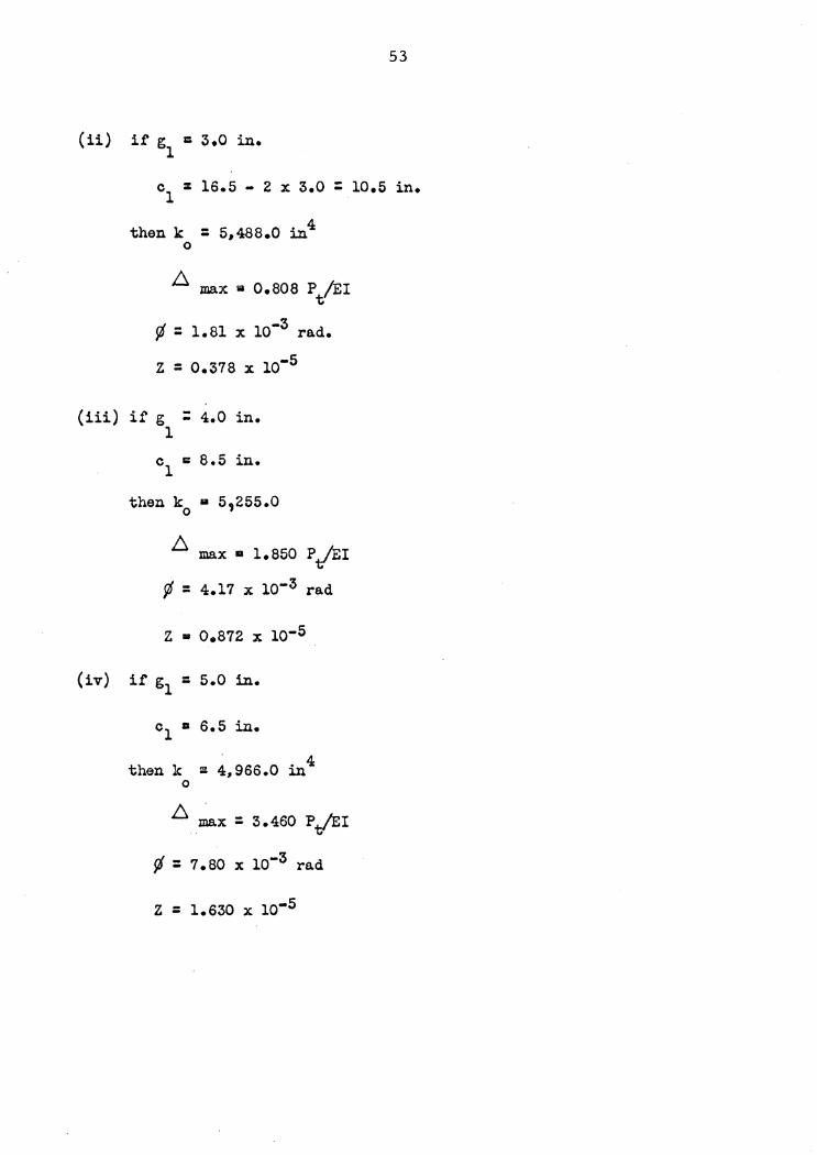
(ii) i.f' g = 3.0 in. 1
53
c = 16.5 - 2 x 3.0 = 10.5 in. 1
then k = 5,488.0 in4 0
b. max a 0.808 Pt/EI
r/ -3 ~ = 1.81 x 10 rad.
z = o.378 x io-5
(iii) if g : 4.0 in. 1
c1 c: 8.5 in.
then k a s,255.0 0
~ max 11 1.850 P/EI
¢ = 4.17 x io-3 rad
z • 0.812 x io-5
(iv) if g1 = 5.0 in.
then k ~ 4,966.0 in4 0
~ max : 3.460 P./EI
¢ = 7.80 x io-3 rad
z = i.s3o x io-5

54
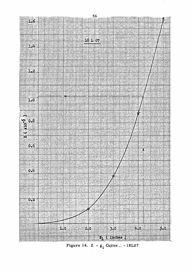
By the use of four trials shown above there are two curves drawn.
One is plotted in coordinates of ~ and g1 and the other in coordinates
of Z and g • They are designated as the rJ - g curve and the Z - g l l 1
curve on the following pages.
By referring to Table 8 the rotation at the fixed and joint of
longspan joist 18L07 is obtained. It the semi-rigid connection is
.capable of developing a rotation or the same amount; then the connection
will satisty the purpose or this thesis. This is achieved by plotting
the value of rJ from Table 8 on the rJ - g eurve. There is a value of g1 ' l corresponding to this¢ value. 'This means that if the stem ot the tee
is cut the amount g1 at top and bottom, the oonneotion will give the
rotation or rJ as desired. The above description is expressed as tollowss
from the rJ = 4.82 x lo-3 rad
rJ - g1 curve,
g1 • 4.2 in•
also by the Z - g1 curve,
z = i.01 x io-5
(from Table 8)
The above values are indicated on the curves by arrowed lines.
(b) Trial and Error Determination of .6:max and Si at Connection
Longspan Joist 24L09
- }.{. 67.6 tt-k (From Table 2)
pt = 67.6 x 12/22.44. 36.i kip

55
Figure 13. Rotation and g 1 Curve - 18L07
57
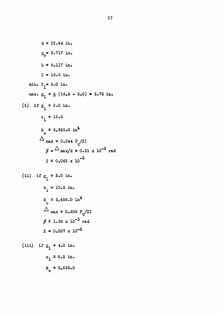
d 5' 22.44 in.
g u 3.717 in. 0
b = a.111 in.
C a 16.5 in.
min. c u 1
5.0 in.
max. g :s i (16.5 -l 5.0) • 5.75 in.
(i)
(ii)
if g = 2.0 in. l
cl II 12.5
k = 5,655.0 i.n4 0
6 max :1 o.244 P /EI t
¢ w 6 max/d = 0.51 x 10⁻³ rad
z = 0.063 x io
if g = 3.0 in. l .
01 g 10.5 in.
-5
k = 5,488.0 in4 0
L max = o.aoa :/EI ~ : 1.68 x io-3 rad
z a 0.207 x io-5
(iii) if g1 = 4.0 in.
c1 = 8.5 in.
k ':s 5,255.0 0

f:s. max :: 1.850 P /EI
¢ • 3.87 x io-3 rad
z • 0.411 x io-s
(iv) i£ g1 a 5.0 in.
c u 6.5 in. 1
k = 4,966.0 in4 0
,6 ma.x m 3.460 .P/EI
¢ • 1.22 x io-3 rad
z a 0.891 x lo-5
58
In the sa.ma way as with 18107 the ¢ - g1 and Z - g1 curves are drawn.
Consequently, the following data are obtained
.from the ¢ - g1 curve,
gl = 4.05 in •
.from the Z -- g1 curve
z • 0.495 x io-s
(.from Table 8)
(c) Trial and Error Determination of ~ max and at Connection ongspan Joist 321
-M: 107.7 f"t-k
Pt= 107.! x 12/30.29 = 42.7 kip
d : 30.29 in.
g = 3.717 in. 0

60'1vZ -aA.tn:J 1s pu-e uon-elo1J ·st a.tn8~Jr
6S

60
~ . .
' t
Figure 16. Z g1 Curve - 24L09
b :0 8.117 in.
c ::. 18.0 in.
min c = 50 in. l
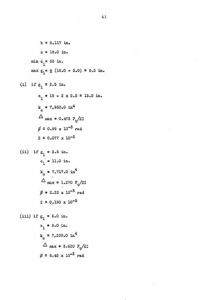
61
max g1a t (18.0 - 5.0) = 6.5 in.
(i) if gl = 2.5 in.
(iii)
c • 18 - 2 x 2.5 = 13.0 in. 1
k = 7,950.0 in4 0
A max a 0.473 Pt/EI
ft = 0.99 x lo-3 rad
z = 0.011 x lo-5
c1 • 11.0 in.
k • 7,717.0 in4 0
'
!:::. max = l.Z70 Pt/EI
¢ a 2.33 x lo-3 rad
z = 0.180 x lo-5
if gl = 5.0 in.
cl • 8.0 in.
k = 7,220.0 in4 0
!:::. max a 3.520 P/EI
¢ = 6.45 x lo-3 rad
(iv)
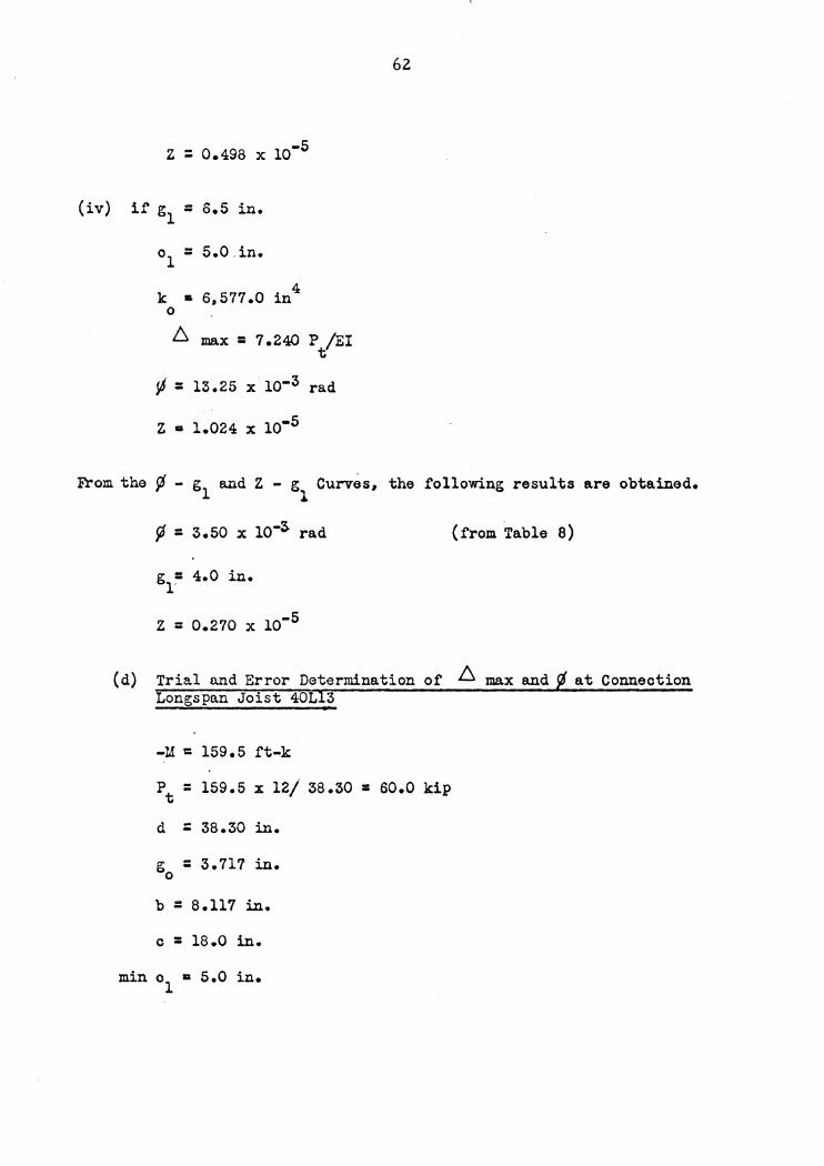
z = 0.498 x 10⁻⁵
i.f' g = 6.5 in. 1
o1 = 5.0.in.
k • 6,577.0 in4 0
~ max= 7.240 P /EI t
¢ = 13.25 x lo-3 rad
Z II 1.024 X io-5
62
From the ¢ - g1 and Z - g1 Curves, the following results are obtained.
¢ = 3.50 x io-3 rad
g = 4.0 in. l'
z = 0.210 x io-5
(from Table 8)
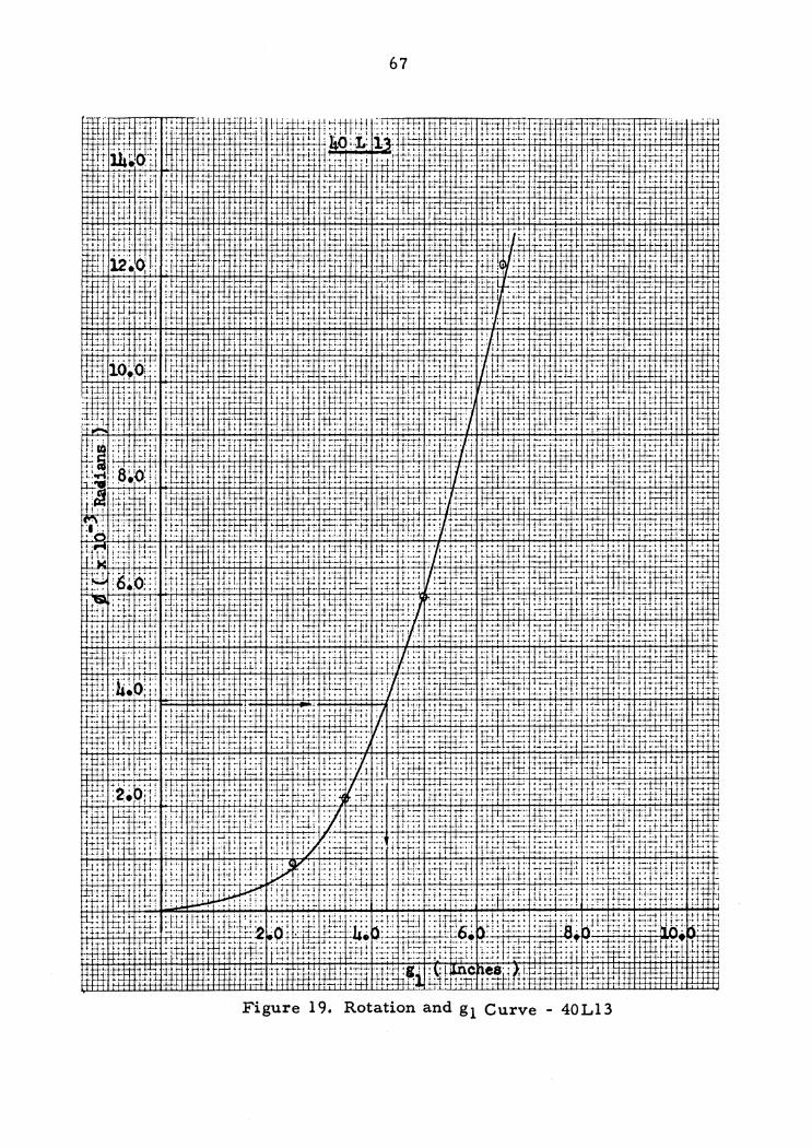
(d) Trial n.nd Error Determination of ~ max and at Conneotion Longspan Joist 40L 3
-M = 159.5 ft-k
pt = 159.5 x 12/ 38.30 = 60.0 kip
d = 38.30 in.
g = 3.717 in. 0
b = 8.117 in.
c = 18.0 in ..
min o1 • 5.0 in.

63
j:, lu .:.;;: 1:-~,· :-·1· ·;1 •-• q.1'_,.1 .. 1.1; :~ F: :.: ,.i j i j·· •I· Ill·: 1:;.r; 1 ;:: :1;::-x: ;.;.1 .•. 1 ... ; 1. ··!·' ..... j·i·····-•.; .. , .. • •... , .. ,.;-j ~·-'; , ... , ·,· .. •·.·-.. '·!.·•,' t 4 •-•• 1-•t•· t I '1•·1~jo ·••l·f•t•t•lt• t•· t l·lt• ~.,~ ,1.I. •·•·•" .,;.~,. •·••·•·l-•1:r -·-·-~.i·~·· ·••·••·11-••I •••-~t• .. •-! ~-01lll~I· ·t
;!itt ·.ttttttt:L ::-.t.!..1J.t.:r ... tt .ltiJJ.: Lt.r lll!lt.t..:.:.t·· !...:.:UJ .. t.t:.L •.• i.±b.:.:J..:.~!~:l..f,j !.i..!. -~: U.L:.:j !. ·r:·~! ~I :·Lt: tt~t;i Lt :t:! !.d.~lll 1tlict
Figure 17 • .'.Rotation and g 1 Curve 32Ll 1

64
Figure 18. Z - g1 Curve 32 L 11
(i)
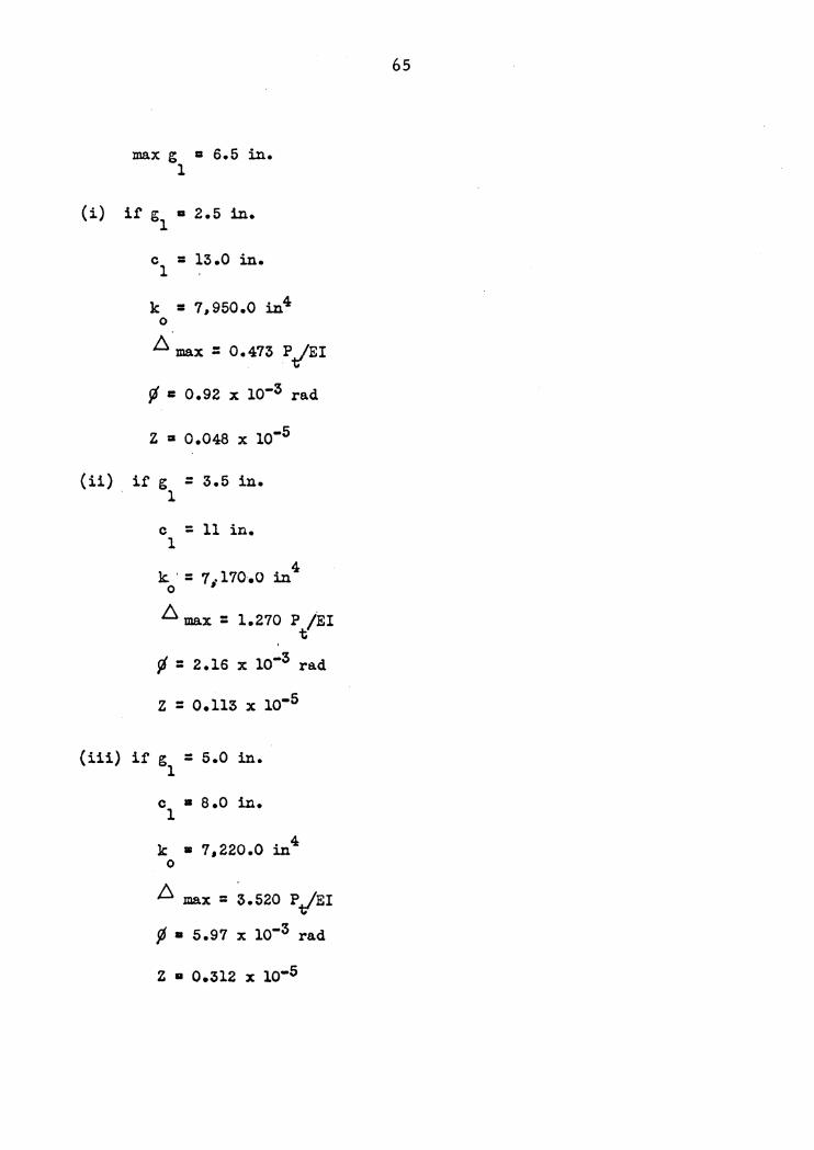
max g a 6.5 in. 1
it g • 2.5 in. 1
c = 13.0 in. 1
k = 7,950.0 in4 0
f!l max : 0.473 P/EI
rj a 0.92 x lo-3 rad
z • 0.048 x lo-5
(ii) it g = 3.5 in. l
c = 11 in. 1
k · = 11 110.0 in 4 0
f!l max = l.270 P /EI t
rj = 2.16 x io-3 rad
z = 0.113 x lo-5
(iii) if g = 5.0 in. 1
c • 8.0 in. 1
k • 7,220.0 in4 0
~ max = ~.520 P.t/'EI
11 • 5.97 x lo-3 rad
z • 0.312 x lo-s
65
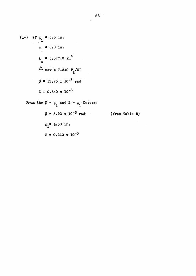
(iv) if g = 6.5 in. 1
C a 5.0 in. 1
k = 6,577.0 in4 0
~~a 7.240 P/EI
¢ = 12.25 x 10⁻³ rad
z = o.640 x io-5
66
From the fl - g and Z - g ·Curves a ' 1 l '
fl • S.92 x io-3 rad·
z • 0.210 x io-s
(f'rom Table 8)
67
Figure 19. Rotation and gl Curve - 40Ll3
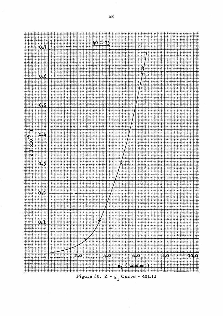
£t'10t -9A.In~ t8 -Z •oz a.tn81Jr ':p . .:.1 .. 1 .. a:!fp-l ·:g±1-+-1-W-i=!=n+1-r1ll!..1-jH!!:q::r:n:rrr::::r...r..1rri:;-n~:;:;-i:~1~·-:;:r;:r+1:n:;:"J:rLu:r.u~-m:i.n:fffrl+'t+rr+rn:m..J..o:r=m:D --H-tH~ p ~~H ~r-t-i-+-r-tr .µ.i..,. ,...~...,. H·i-···-~-t. ~ ~ t·t !"-~ ........ .___~ !--t-r···rT-·r 0 r-t ... "!"""l-d·r~.1-d-~ ~l-H-+-·~+rH ~-!""t"~~r!-+ r-t•+t·'·H-++-1T~l=rrn
_._._.... ...... ~...._~ ...... -·~+_.-j-11.J~-.:: !-; t :; ::~ ; ; ~;Ji: i-~ : ~: q .~ :; ! : : ! :t..;:; :•tt ; r::, .. +: +; E.£!_ ..;:t+t·+'""..,~ 1.i::;..,""'i.-·i.::i1+.~'-+..l.:;..J..l-l-++-H-;.+1-1-;...;..i>+;+i~ ;1-81tt:oi ""' t+tTIJl~~utii!'T'"~"''; Citif'+±r): ;:~~+ti=L~·--lb=~ i:t:t .. :. i""' ,, .. ;--·1-n .• , .... ,. ... ,. '"•·1·_,., ·····µ·--· •···r··''-•11··f; .... ·•·· ., .. , .1, ... ,r··:··• ··-:•+_"' -o. 1ot:i:;1:: : ::h~o ,g; :f:::~·:: : :·:: .. o. 9: :.: :~: ~ ~:~i~ :o· tr::, !:!\7,: :=; ;i: :o a: :1; ::: , _Iill. ~• :1: r:i. '.tttM~f{iii
,.,, ... ,,, ..... ,. , ... , ...• -,~·-··:· '!'' .. ,!. ······1·· .....•.. , ... ,1 ····!······ -~···•1 ; .. ,..;1j~ ::::::1:1:·: ::: '!:: ::1=:: :1: :;:~': ::~~: '.; :i ::~.i~: :: ~:1· :t:'t;:;:'::::: ti.HJ:t!-i ~1r:1:1
ii-ii-riiii ii-~i!~-fr~ ~~ittt i~~-i1jE: iitir ;i -~~-~~10 ~~;~r;;~ H-~i:i;¥i i~i~w ;.., ;.i l ;J .. 1 .. ;. ;.;. ;~ 1-; ; .•. ;. '" '! l,.'' .. I; 'j'.;.; ! j-·. J"j; ·1: ;.: '-i-~;; .. :_ 1 ·_.'·I·; ... ,. 1-l j i·'. ··!: i.' i-.-::. ·_: ;,i:•; 'I ;~~!~.ti -'-j' -~-;.'.-;= ;;=;; -~-~;-t:: ~~; ;~;;1;-~~-;-f ;_;-;· ;;:;; {~~-; 1 r-i~ 8~F: :_·:; :; 1 :;:.: : i-; ;1JHn~ -4f~~~ :~J;.-rnr=-~ .... t,j::•·· ···t+-/l··'-··· .. 1J,,,... .. ·-r•··f··1r; '-1··1· ,,. l••"'-1 ·· ·'•··!·1.l-. : .. ,... .. , .. , .. ·-·-;-\,! .. "'-r , .. ; ·•1•·!r r-·~ ... --........ t•.•,-t..,.·--·~· :·t-~'•-t -'·-:-1;··~-:r-ri~··· ·t··· :····r··_·'. ··~+ -•t!•· ·•""f•· ··~~ ~-~-··!t·~~· ·~·· '!··+ ·t·•···t· .-
~1!~; ~!-~~:JEr~t~~tm~ :~T:~ ;f~r1i'.t~~ fi:~'.1~t:~ -;~~WJ~r:~~~-~ ;-r;±%~Sfji1J;1fJ1 ~f:'.t ffi~l1-:;1~E :wtt +1 • +1-·-· j-i-!-1 • t-•-'1·:; • •. , .. d, i '"'·•·:· _,_, • .. t.,. ,.,. ; t ··•···:-• •. I.•' L. . , . . · J-· .• ··l ·.,.;ti .. , .. ,.,, .. ...., ... ; i'4 rt-'-'·· '~-; l" ;. -• ·! .,,.,.,i_-~ ·-·•t-+t· _..,.,.... .. ,.~,t-t-• ·-~·:tt·-~i-0-•·t-'·t~t-! --4t~1· •• · •··.~-t-· •·•·1-•1··-~ .. ~ ··~-·r•·r-•t • •··1-tt·. ~·r•rrt ~.
f,i ~;r; ;!~~ i:t~i' i~ ii fr ·:::':~~; :if'.:; i;f r ~T lit ~ ·j''·' ...... .:-r,.r, ;1 .. ··'--· ,.; .. :.1,,1.. l'-''-i"r'· !!·•··t··i•·' .. ,!.;l.'r' .b .. ,1.jj· •t·r•J,.,1.. -••1-1--I" ··••-• l_.~ .• 4........ · -•l-•·4 41-•-i~ .. ~r•· t•·r1·r•-•-•• ; .• -';· l-1 .. ;. !!+•l·'"·t!""t ++..._. ~ -~ ; .. ,.-,.~;L -~l-•-tt-f·
:.:;;l(; ::: : l ~-: :::: :: ·l_::: Ji jid..:;::: ; .. 1~ : .. p: 1 j i:! i~ I:..;; : :::rp: ;:j :..~ l: ~
....... h-jf+....;...+.-...... ..+ ............. h-j~l+t· ... ~ ... t ... · ... ~· ... f.-:-~-~+-. '. ..... ,:·:;: rir t~!~,!f ~ f il#,IT,}t ti~~ ~t~r· !~f! 4 ,.,_, ·t ~· •-i-~r+! -t-t-o o-1"'!'"6 • ~ •-r •-o ·• '• • •-•·•· .. .,.., .. ' -•i-•·)_t·! r. ·~"'!-•·•·•-t-• '~ 1·• t-t·l •·i 1 • · rt·•-~J_.., 1 .. , • +·•TI • ,.;.,. t- !-; r-.; .~; H-;_;_;,;.;, .... ~.,...;m;-!;.,t:. ;JQ" .. ' ,, .. ,; .:c, j .• ~ ·-· • ',~1:;;:;; r:.1.~1;:;.~; j" ;:~T ~ i~ :I~!!; .. ;; I; 1-,.j H
.:~111t~s-;;~-~~:~-t~ ;:r~?~rn ;~ti: ;~1;;~~.t~~ ~;=~:~-;-~~r ~~fl~;; 1~J{,_t~;1 f-fu.-;::..n F;:; m.fr~r i; ,...,f"I....,··-·-.... j ..... , ............ r;.... ... ; ,,,.. .. 1.1.. ... .r .. ,1 .. ····-·t·····--~.,. .• .1. ..... , .... 1~,,~ .• 1 •. ···'-l+·t' ., .. ,,i .• ,.,, •• ffi .. µ-, ... t;-°lr+,1-•·1t-1l-•1•·• ·•·r••rj1-•·· f"''J" •·•'-···' '!!:.:· , . ., .... •-••·;•·tj· 11-•·· +t•·• .,., .. , •·r;+-•·h:-"f:.11-t -•J-1, ,rl,.1-f.1., .. ,.1-+1 :::+~ !°''""~ i::ft-~t~: .... :::;:~.::'.:-j:ii..~! l:i:;ij:.r:; ~:W::;.~1_:1,,,"'H' '"·'';'"!':;''':' ::rriiii ''" !'i,~:tt•n1:; ::ID]. H -;:i-, ~~~; ·"; t '..:-;r:::_; :-;:s:•_;:~;: ;~~ ... _,_·;:: ;:·: .6:-j!: :~:]-.. ·:.::_ ... -~~-:;_--~-~;;-~~;.·: --~~_-::_-_ ;~;~ ~~ ~~: ~~~:>i !F7f~_·:~~T 74;_-1 r~ -:-rL~· -;~--!~.· n·ii-f:~~-;1· :~ n:rr:~~:~! :·!·-w:fr::~!t : : ~-:T;trt"lTr~-ru1 ·:_ ::~rn·.~_; r·~:: .:·:_::f ~Hi· }fl~ ~Tr r ·q_rt:_T: :.·~ r.r;.t tl·f1:.· r. t·; r.ril
:·: .. :b=:wi::-::1:;;1= _,...-++++...,_-H--H--+--,_...,_._. _____ ++-r-+-·,_....,...,_.,__,__,+--....,_H·.,: j~} i1~frf ~+----:-. ;__,._,...~++..+_.._,_r,_,t-Hr;--<+-_...,.++.._,.+-+-H-...._
:;.:::~-·-rt:~:t;.~T~
;.t-:::· f1-; T·r'f ff.t~--.~:!i ~-£!-t-~1-f .H-i1-~11-f lEtit4~::1 -· t-t. _, ..... r ~-!·~~-:t ·-·. ··~-r-rf"77-~ .. --• ,4 ... p., ...
··1j j. -.i-~r r·i . ; .. .,.! ·• ··-· l ·•·+ +: ·'·++··. h'· '.~!:Pt:""'±Li· ;-:~-::I ~;~..i ·;-i ~: .. f,iJ' :-i_ iiJ[:!-t; -H.._._.._.. ..................................... -.. _~}+6+-;; ... 1-.... 1; .... :~-;['"'-~"' ......... i: :rt~~~:; ~:ii~)iff ·-,-· ,, . ' _ ri-:-:.~ w· n7~ :1t:: J~-t~~~ ~fJJJ:~~-~ f-j:[~--~:~f:: -'·ri· .... ; 11 .. -•n -·,. r !-••··;.. -ti+·-•. ; .. , 1-:. '·I-;-'-; . ., ,-!_1, ... -,-.... •T•-1-+~·t·t·+~~-t· •y•-•-••+~J~·;..~. ·-·;:·-•·o-i-'. tt•·•1t·tt-1
;TFh· ilf~.., H •-H~l '-!t i-1_•i•:I:...l1 '-H i-~i--h-H ,.1 ! ;~ i-H-H-H ; .. ;;; l-irr+-1~ :t l-i-"i-;t' r·r: I; .;7 h1 f-H~ht f r-l i ~I t-!-t-! f 1 H~-1-ii~-t li-1++1-t-:
99

( 3) Deaip of' Welding at Connection
It is specified bT the •neaign of Welded structural Connections"10
on the basis of teats that a fillet veld vitb transverse load tails on
a plane at 67-1/2 degrees to the horizontal. Thia is the throat
aeotion having the greatest shear 1tre11 in the conventional ~5
degree equal leg fillet veld. The al.lovable load per inch baaed on
the allowable unit shear stress 1118¥ be calculated u follows tor a
leg size of "e" inches.
shear on throat • 13,600 x l x 0.765 x e • io.~oo e lb/in
al.lovable P • 101400 e/ain 67.5° • 111300 e lb/in
According to the fonnal.a shown above 1 the aize of fillet veld
tor connection of longapan Joist 18L07 ia designed.
Pt • ~/d • 39.8 x 12/16.59 • 28.8 kips
it e • 5/16 in • 0.3125 in
then the length of fillet veld Lt required i••
L • 28.8/(ll.3 x 0.3125) • 8.2 in
the actual length of fillet veld is, .
Lact • 2 x 8 • 16 in > L • 8.2 in o.K.
The sises ot welding at the connections tor the remaining Joists
are detel'Dlined and will be ahovn on the figure ahaving the test
sections.
70
9. Choice of' Column Stub
The column which was chosen by Combs vaa a 12WF1'0. This column
vaa used tor all test sections as being ot representative depth and
possibly' of' representative veight.
10. The Test Sections
The test section ia 11ade ot a column atub 1 the end panel ot tvo
joists and the connectione.
(l) Stiffener Desip
Since the bottam chord is under campresaion and top chord is
under tension, it ia necessary to provide stitteners 'betveen the
column tlanges to resist these concentrated loade. It the etittener
is designed for the maximum load ot the tour test sections, it will
be adequate tor all sections because the column stubs are all the
same size. The following design is baaed on the 1956 AI3C Speciti-
cation.
max. Pt • 159.5 x 12/38.30 • 50.0 kips
length ot stiffener • 10.91 in
width ot stittener • 3.125 in
try 5/8 in plate, A • 1.95 in2
I • bh3/l2 • 3.125 x (5/8)3/12 • 0.0636 1n4
r • ./'f7I • 0.18 in
L/r • 10.91/0.18 • 61 < 120
Tl
tc • 15.08 k•i
tact • 25.0/1.95 • 12.8 kai < tc • 15.08 kai o.K.
Use 10-T/8 x 3-1/8 x 5/8 Stittener each aide
(2) Vertical Web Check
The test section is deaigne~ to be supported at the Yertioal veb
•m.bera (see Figure 13). The stress ii checked aa follows
Use l in JtJ bar tor all aections
r • 0.289 in
(a) 18L07
L • 13 in, L/r • 45
tc • 16.02 kai
Pv • -M/P
• 39.8 x 12/24.o • 19.9 kipa
t t • 19.9/l.O • 19.9 kai > t • 16.02 kai ac c
The maximum test load, P , it the vertical veb member is not max to be over stressed, 1st
P • 2 x 16.02 x l • 32.0~ kips max. the vertical veb vill yield at loa4,
Pyield • 32.04 x 1.67 • 53.5 kips
(b) 24L09
L • 18.5 in, L/r • 64
72
re = 15.0l ksi
pv = 67.6 x 12/30.0 a 27.0 kips
fact = 21.0 ksi > fc a 15.01 ksi
P = 2 X 15.01 = 30.02 kips max. Pyield • 30.02 x 1.67 = 50.5 kips
(c) 32Lll
L • 26.0 in, L/r • 90
re = 13.07 ksi
PV • 107.7 X 12/36 • 35.9 kipB
tact = 35.9 ksi > f c = 13.07 ksi
P = 2 x 13.07 x 1 • 26.14 kips max. pyield = 26.14 x 1.67 a 43.7 kips
(d) 40L13
L • 33.5 in, L/r • 116
f c a l0.47 ksi
Pv • 159.5 x 12/48 • 39.9 kips
f t • 39.9 ksi > t • 10.47 ksi ac c P • 2 x 10.47 x 1 • 20.94 ksi max. pyield • 20.94 x 1.67 a 34.9 kips
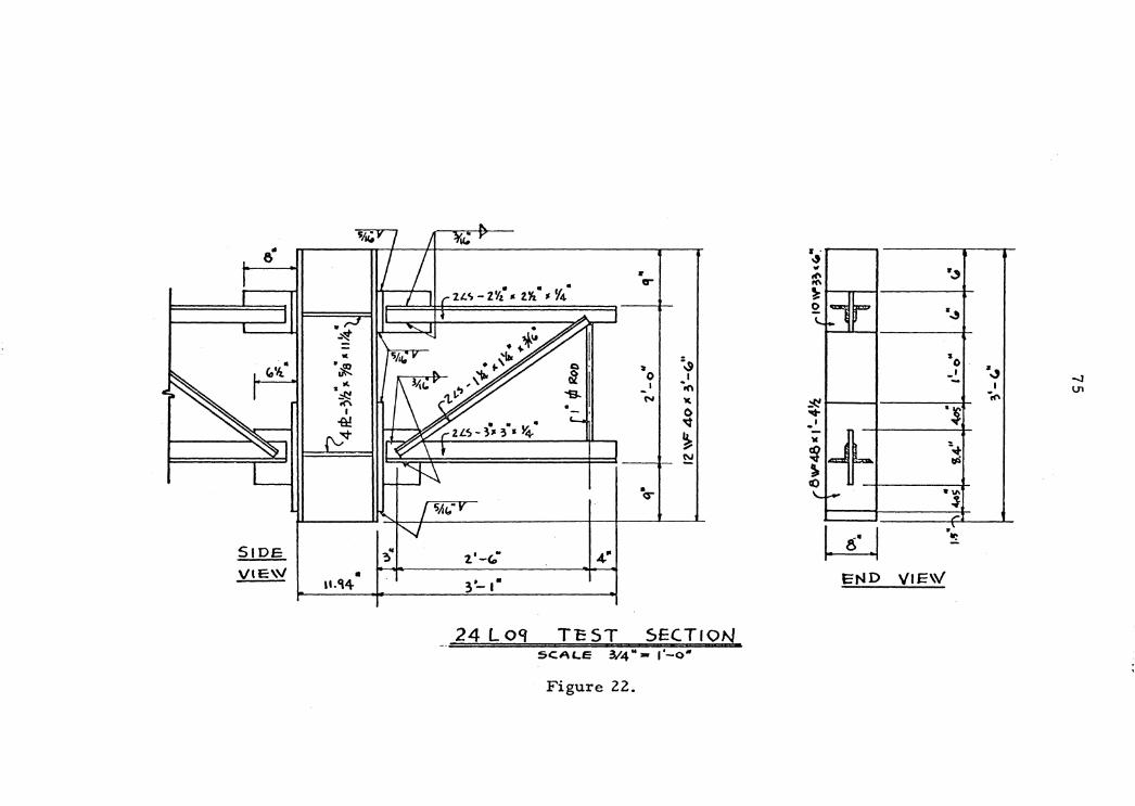
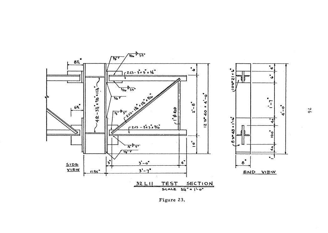
The vertical web members are all under designed. This is because
the author was reusing the old test specimens which included the verti-
cal veb members vhich vere all originally underdesigned. The yield
73
strength ot each vertical veb member in comparison with the maximum
teat load that recorded in laboratory part of this thesis is very
close.
On the tour tollowing pages are scale drawings of the actual
sections.

.. ..,, 1o'k .. • rs· N • VJ 0. • ~ ~
CT • ~
: " 0 I .. • &
"' 0 •A • ,.j) ~ '6 .. ,; It 0 -..J
.I -.!. I ~ .0 N -r(\ .. .q IC
f ~ <D s 'It CIJ
~ Cl
.. ~ er ~
~ ."" . ...
• • 4• ~ 1. -o
"·'14 .. 2·-1·
SID.E VIE\V END V IE.\V
tS L 07 TEST SEC.Tl ON SC.ALE: 3;4"= l~o"
Figure 21.
6
.. Co~
SIDE VIE\\/
I(
.i!
• ll-C\4
• • • • er
21.c,-ZYz "tl'i ,. Y4
I =.., !i lt 0 I I ·in
N " • () - ' 'lit ~ ~
·o-
2'-t:' 3•-1·
24 Loq TEST SECTION SCALE 3/4" • l'-o•
Figure 22.
~
"' .,,
~ 0 ti llC>P . ..,, ~
s O· .J _, - I
-1('
I ·~
co
- t • ~-it lid
~
'- ...... ."' ~ -'
END VIE\V
4 8~
• • ~..,, v ZLS- ;. '>• • ~" ~
" • N
.., ~ 0
• l( .,\,\D 0 ·~ I w .. +
~I -""" r-"' • ~Ile • I "' cO ·o • ~· IC :::t:! I -J rn ' -C'I 0 I 0--5• •• ;' ·.q-I 1Y "S- ~ ~ • ~
. .., •o v _, .q:.
N -• f ~ •o 6 ~
: cO 0 q ...,
w • -II
~· . 4• $\t)~
; -o
~ 3'- • END Vl°E''V 11. 4"
.32. L 11 TEST SECTION S.C:.ALI:. ~/4"• l'-o"
Figure 23.
• 0
:: 0 ' ~
"' • I(
v 0 ~ -l ~ ll{ t('\ ~ "$I N •
. . . . ZL.S-3"2. x-; I( 3/~
= 0 5•
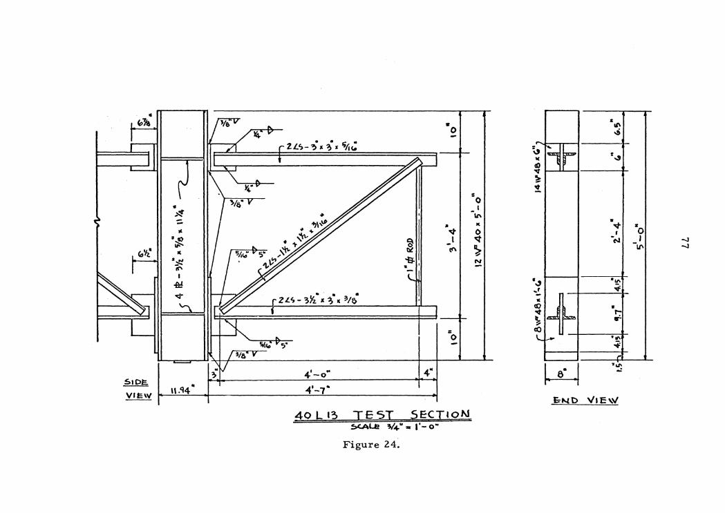
41 .. -o 4"
40 L 13 TE 5T SECTION ~I.Ji V4" .. I'- O"
Figure 24.
-;, ..... t( ., r d)
""' ~ 'It
• .3 ~' - t " fl:) ~
'b \.... -C()
& II\ ..;
~...,,
• ...,. , -~
. "' ~
& I"-r
• II\
~ ,. .. .,. ..:
• 0 I
-LI\
'
78
:&. LABORATORY IBVESTIGATION
1. Fabrication ot Test Section
The teat sections were fabricated originally in 1961 in Iqnchburg,
Virginia, at the Montague-Betts Steel Plant. Then the test sections
were modified and refabricated by the author with the assistance of
Mr. Marshall K. Smith in the Engineering Mechanics Laboratol")" at the
Virginia Polytechnic Institute.
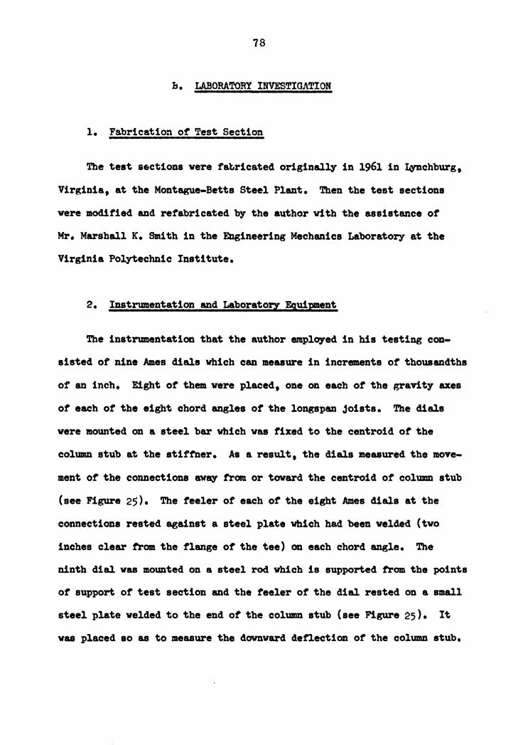
2. Instrumentation and Laboratory F.q,uipment
The instrumentation that the author employed in his testing con-
sisted of Dine Ames dials which can measure in increments of thousandths
of an inch. Eight of them were placed, one on each of the gravity axes
of each ot the eight chord angles of the longapan joists. The dials
were mounted on a steel bar which was fixed to the centroid of the
column stub at the stiftner. As a result, the dials measured the move-
ment of the connections away trom or toward the centroid of column stub
(see Figure 25). The feeler of each of the eight Ames dials at the
connections rested against a steel plate which had been welded (two
inches clear trom the flange of the tee) on each chord angle. The
ninth clial was mounted on a steel rod Yhich is supported trom the points
ot support ot test section and the feeler ot the dial rested on a small
steel plate welded to the end of the column stub (see Figure 25). It
was placed so as to measure the downward deflection of the column stub.
79
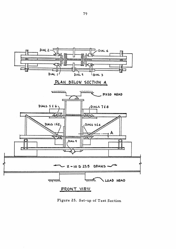
.DIAL Z. :1-----
PLAN f>ELO\V SECTION A
FRONT VIE\V
Figure 25. Set-up of Test .Section
80
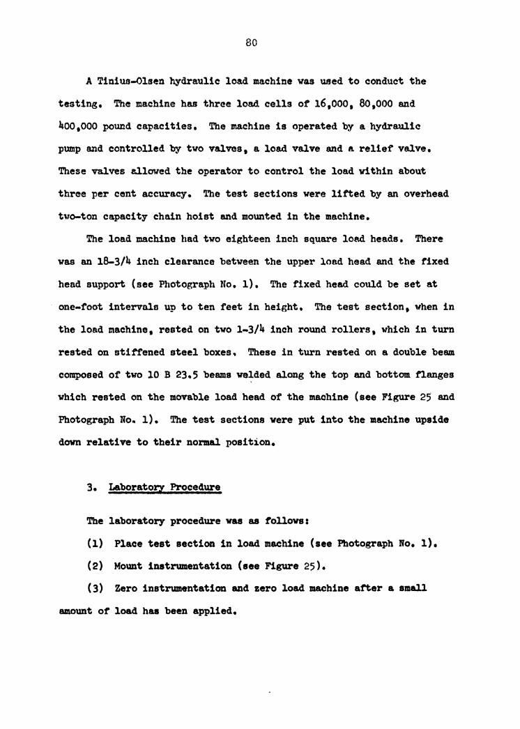
A Tinius-Olsen hydraulic lo&d machine was used to conduct the
testing. The machine has three load cells of' 16,ooo. ao.ooo and
~00 1000 pound capacities. The machine is operated by a hydraulic
pump and controlled by two valves 1 a load valve and a relief' valve.
These valves al.lowed the operator to control the load vithin about
three per cent accuracy. The test sections were lifted by an overhead
tlTo-ton capacity chain hoist and mounted in the machine.
The load machine llad two eighteen inch sq_uare load heads. There
was an 18-3/4 inch clearance between the upper load head and the fixed
head support (see Photograph No. l) • The fixed head could be set at
one-foot intervals up to ten feet in height. The test section, when in
the load machine, rested on two 1-3/4 inch round rollers, vhich in turn
rested on sti:f'i'ened steel boxes. These in turn rested on a double beam
composed or two 10 B 23.5 beams velded along the top and bottom flanges
which rested on the movable load head of the machine (see Figure 25 and
Photograph No- 1). The test sections were put into the machine upside
dovn relative to their normal position.
3. Laboratory Procedure
The laboratory procedure was as tollovs:
(1) Place test section in load machine (see Photograph No. 1).
(2) Mount instrumentation (see Figure 25).
(3) Zero instrumentation and zero load machine a:t'ter a small
amount o~ load has been applied.

81
Photograph No. 1

82
(4) Load test section to point or failure ot joists.
( 5) Take dial readings at ap:propriate intervals so that behavior
curve Ill83' be plotted and dralm.
( 6) Observe behavior or all the component part of the longspan
joists• connection, and colunm stub.
(7) Note any behavior patterns or peculiar characteristics of the
specimen as it is loaded.
4. Data -The arrangement of' Ames dials was as f'ollowss dials one and two
were on opposite sides of top chord• dials three and tour were on
opposite aides of the other top chord, dials fiYe and six were on oppo-
site sides of bottom chord and on the top of dials one and tvo, and
dials seven and eight were on opposite sides of bottom chord and on the
top of' dials three and four (see Figure 25).
The presentation of the data is as follows:
(1) A sheet of raw data tor each of' the tour test sections.
( 2) A sheet showing the aYerage ot the readings at each pair of
dials at each connection.
( 3) A sheet showing the total displacement at the joint• the
joint rotations. and the moments corresponding to the loadings.
( 4) De.ta CurYes plotted tram Joint rotations and moments.
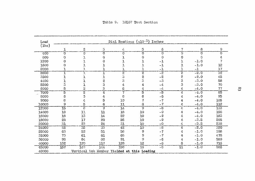
Table 9. 18L07 Te·3t Section
--- -----Load _______ pial Rea.Clings (::U.o--3) Inches (llJs) ----
1 2 3 t.!: 5 6 7 8 9 --0~-400 0 0 0 0 0 0 0 0 0
000 0 J_ 0 l 0 0 0 0 4 1200 0 , 0 1 l -·l l -1.Q 7 .!..
1600 0 .l 1 1 l -1 l -1.0 12 2000 1 1 1 1 J.. -1. 1 •• J_ J.7
~800-----r ~i:--·----1 2 2 ·-2 2 ... 2.0 3~ 3$00 1 1 l 5 2 -2 2 -2.0 l-5 4400 l 1 2 3 3 -3 3 -3.0 58 5200 3 1 3 4 4 -4: 3 -3.0 70 6000 5 2 3 6 4 ·-'1 4 -4.0 77 co -- :-:r: 0
w 7000 5 2 4 7 5 -5 4 65 8000 6 3 4 8 6 -S ~1 -4.0 95 9000 8 4 5 10 '7 -7 4 -4.0 105
10000 9 5 6 11 8 .. 7 4 ·-4.0 112 12000 15 ·-·a-- 9 --J::r- 9 -8 ~:- -4.0 135 14000 18 11 11 18 10 •. fl 4 -4.0 158 16000 18 13 14 22 10 -S ,•
"J: ···1.0 183 18000 28 17 20 26 10 -9 ~ -3.5 205 20000 31 23 24 31 10 -0 11: .. ,. ,-
-.;>.;) 238 21.WOO ·1:5 55 33 ·1.1:2-----10 ------:-s---· 4 -2.0 320 28000 6'Z ,) 52 51 58 9 -7 4 ·-1.0 398 32000 73 61 61 68 9 .. 7 4 -1.0 478 36000 98 8'1 80 91 9 -6 t.i: -·1.0 589 40000 132 120 117 128 12 -G 6 --l.O 716 45000 ~7 "119 l·H 1513 i6 ____ :G
11 -1.0 886 4.8!)00 Ve~.'.'tica.J. Web Membe1· Yielded .!'-~th~-~.· Loadi~g -·--·-.. ---
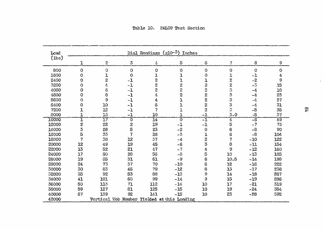
TabJ.e 10. 24L09 Test Sec·l;ion
Load Dial Readings (xJ..o-3) Inches (lbs)
l 2 3 4 5 6 7 8 9
800 0 0 0 0 0 0 0 0 0 1600 0 J. 0 l 1 0 1 -1 4 2400 0 2 -1 2 1 1 2 -2 9 3200 0 4 -1 2 2 2 2 -S 1-5 4000 0 6 -1 2 2 2 3 -4 18 4800 0 a -1 4 2 2 3 -4 25 5600 0 9 -1 4 1 2 3 ·-f 27 6400 0 10 -1 0 1 2 3 -4 31 7200 1 12 -1 7 l z ~ -5 35 CX> ..., l:-: 8000 1 r7 a -1 10 l -1 3.0 ·-5 37
10000 1 17 0 14 0 -1 4 -6 4,9 12000 2 22 2 19 -1 -1 5 -7 73 14000 3 28 5 23 -2 0 6 -8 90 16000 5 35 7 28 -3 l 6 ·-S 104 18000 7 38 12 37 -4 2 7 -10 122 20000 l2 49 19 4.-5 -6 3 8 ··Lt 154 22000 15 52 21 47 -7 4 9 -12 160 24000 17 GO 28 56 -8 5 10 -15 185 26000 19 65 51 61 -9 6 10.5 -14 198 28000 24 7'.3 37 70 -10 6 12 -16 222 30000 30 8:3 45 79 -12 8 1:5 ·-17 238 32000 35 92 53 88 -13 9 14 -.18 267 34000 41 101 60 99 -14 9 15 -19 286 36000 50 ll3 71 112 -14 10 17 -21 319 38000 59 127 81 125 -15 10 19 -24 554 4.0000 67 139 92 l~l -15 10 25 -28 S92 42000 Vertical. Ueb Member YieJded at t.his Loa.di~
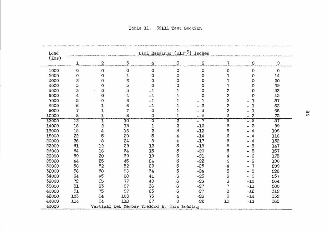
Table ll. 32111 Test Sec·i;ion
Lead Dial Readings (xio~·3) Inches (lbs) -
l 2 3 4 5 6 7 8 9
1000 0 0 0 0 0 0 0 0 0 2000 0 0 l 0 0 0 1 0 14 3000 2 0 2 0 0 0 1 0 20 4000 3 0 3 0 0 0 1 0 29 5000 3 0 3 -1 1 0 2 0 32 6000 4 0 4 -1 1 0 2 0 43 7000 5 0 6 -1 1 - 1 2 - 1 57 8000 6 1 6 -1 1 - 2 2 - l 62 9000 7 1 7 0 1 .. 5 2 - 1 68 00
10000 8 1 8 0 l - 4 3 - 2 73 \Jl
12000 12 1 10 0 2 - 7 3 - 3 87 14000 16 2 13 l 2 -10 3 - 5 99 16000 18 4 16 2 3 -12 3 - 4 108 18000 22 5 20 5 4 -14 3 - 4 116 20000 26 8 24 8 4 -17 3 - 4 132 22000 31 12 29 12 5 -18 3 - 5 14:7 211000 S4 16 34 15 ~ ~20 3 5 157 v
26000 39 20 39 19 5 -21 4 - 6 J.75 28000 44: 25 45 24 5 -22 4 - 6 190 30000 50 32 52 29 5 -25 i.J: - 7 209 32000 56 38 !.::-·"".' 34 5 -24 5 - 8 226 ._,,~
34000 64 '-'LS 68 41 G -25 6 - 9 237 36000 72 55 77 49 6 -26 6 -10 264 :38000 81 63 87 56 6 -27 7 -11 280 40000 91 75 97 G5 6 ·-27 8 -12 312 42000 103 C:4 108 75 4: -26 9 -14 332 44000 114 94 118 87 0 -22 ll -lG 365 44000 Ve:L·tical ~ Member Yielded a·(; this Loading
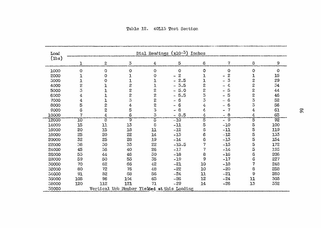
Table 12. 40Ll3 Test Section
Load Dial Rea.clings (xl0·-3) Inches (lbs) -----
1 2 3 4 5 6 7 8 9 ·-1000 0 0 0 0 0 0 0 0 0 2000 1 0 1 0 - 2 l - 2 1 15 3000 1 0 l 1 - 2.5 1 - 3 2 29 4000 2 1 2 1 .. 3.5 2 ·- 4 2 34 5000 3 l 2 2 - 5.0 2 .. 5 2 44 6000 4 1 2 2 .. 5.5 3 5 2 46 7000 4 l s 2 6 3 6 3 52 8000 5 2 4 2 - 6 lJ: - 6 3 56 9000 6 2 5 3 8 4 - 7 4 61 CP
0\ 10000 7 4 6 3 .. 8.5 4 8 4 65 12000 lO 8 9 r.:: v -·10 5 - 9 5 92 14000 15 11 13 8 -11 5 -lO 5 100 16000 20 15 18 ll -12 6 -11 5 119 18000 25 20 22 14 -13 6 ·-12 5 133 20000 32 25 28 19 -14 6 -13 5 154 22000 ~)8 30 33 22 -15.5 7 -15 5 172 24000 45 36 L.J:0 26 -17 7 -14 5 193 26000 53 44 48 30 -18 8 -16 6 206 28000 59 50 55 35 -19 9 -17 6 227 30000 70 62 66 42 ·-21 10 -18 7 248 32000 80 72 76 48 -22 10 -20 8 258 34000 91 82 88 56 -24 ll -21 9 280 35000 105 96 104 65 -26 12 -24 ll 303 38000 120 112 121 71 -29 14 -26 13 332 38000 Vert_!caJ. ue·b Member YieJde_d_~_!. this Loading
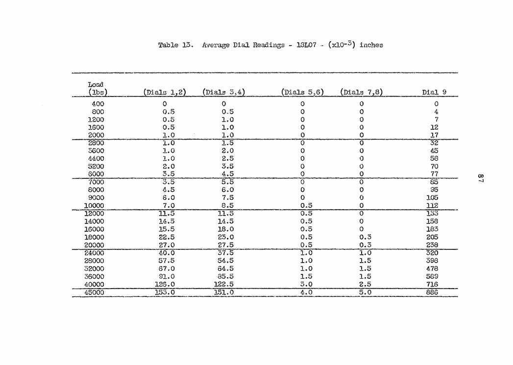
Table 13. A:ver~ae DiaJ. Readings - 18L07 ·- (xio-3) inches
Load (lbs) ~Dials lz2) (Dials 3~!2. (Dials 5,6) (Dials 7z8) Dial 9 400 0 0 0 0 0 800 0.5 0.5 0 0 4
1200 0.5 1.0 0 0 7 1600 0.5 LO 0 0 12 2000 1.0 1.0 0 0 17 2800 1.0 1.5 -0 0 32 5600 l.O 2.0 0 0 4..-5 4400 1.0 2.5 0 0 58 5200 2.0 3.5 0 0 70 6000 3.5 4.5 0 0 77 o:> 7000 3.5 5.5 0 0 85 -.J
8000 4.5 6.0 0 0 95 9000 6.0 7.5 0 0 105
10000 7.0 8.5 0~5 0 ll2 12000 11.5 11.5 0.5 0 133 14000 14.5 14.5 0.5 0 158 16000 15.5 18.0 0.5 0 183 18000 22.5 23.0 0.5 0.3 205 20000 27.0 27.5 0.5 0.3 238 24000 40.0 37.5 1.0 1..0 320 28000 57.5 54.5 1.0 1.5 398 32000 67.0 64.5 1.0 l.5 478 36000 91.0 85.5 1.5 1.5 589 40000 126.0 122.5 3.0 2.5 716 45000 153.0 151.0 4.0 5.0 886
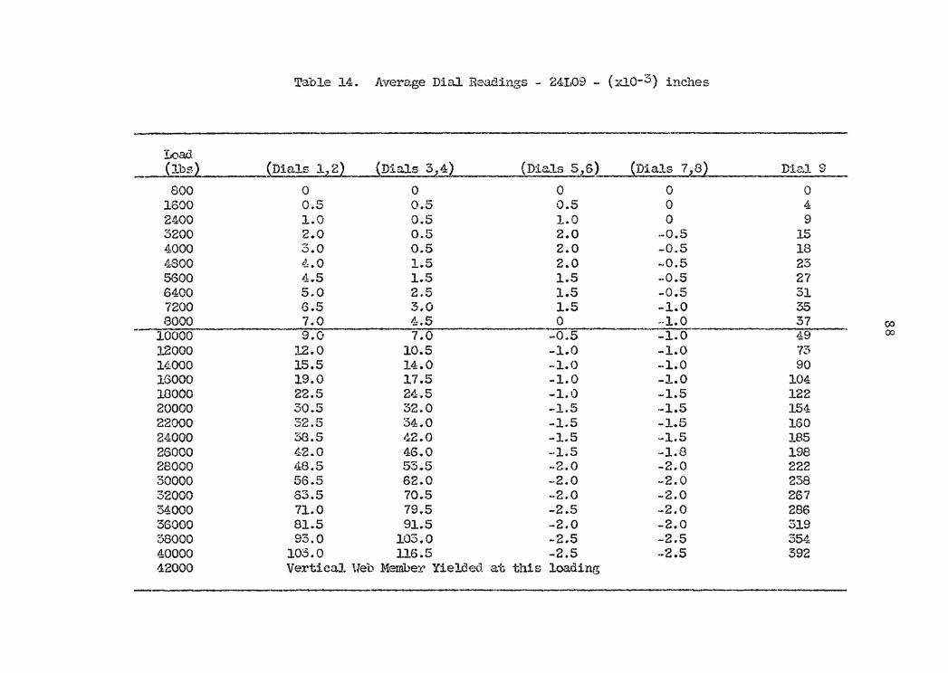
Table 14. A:vera,ge Dial Readings - 24I,09 - (xio-3) inches
Load (lbs~ (Dials 1z2~ (Dials 324) (Dials 5,6) ~Dials 7z82 Diz,1 9
800 0 0 0 0 0 1600 0.5 0.5 0.5 0 4 2400 1.0 0.5 1.0 0 9 3200 2.0 0.5 2.0 ·-0.5 15 4000 3.0 0.5 2.0 -0.5 18 4800 t!:. 0 1.5 2.0 -0.5 23 5600 4.5 1.5 1.5 .. Q.5 27 6400 5.0 2.5 1.5 -0.5 31 7200 6.5 3.0 1.5 -1..0 35 8000 7.0 4:.5 0 --1.0 37 00
10000 9.0 7.0 -0.5 -1.0 49 00
12000 12.0 10.5 -1.0 -1.0 73 lLlOQQ 15.5 14.0 -l.O --1.0 90 16000 19.0 17.5 -1.0 -1.0 104 18000 22.5 24.5 -1.0 --1.5 122 20000 30.5 32.0 -1.5 ·-1.5 154 22000 52.5 34.0 -1.5 -1.5 160 24000 38.S 42.0 -1.5 -1.5 185 26000 42.0 46.0 -·1.5 -1.8 198 28000 ;18.5 53.5 -2.0 -2.0 222 30000 56.5 62.0 -2.0 -2.0 238 32000 63.5 70.5 -2.0 -2.0 267 34000 71.0 79.5 -2.5 -2.0 286 36000 81.5 91.5 -2.0 -2.0 319 38000 93.0 103.0 -2.5 -2.S 354 40000 10::5.0 116.5 -2.5 .. 2.5 392 42000 Vertical. lleb Member Yielded at this loading
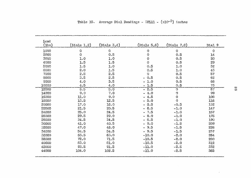
Table J..5, kverage Dial Readings .. 32Lll - (x10-:'.5) inches
r.oa.d ·- (lb?_)_ (Dials lz..?l_ (Dials 3.~J_. __ {pials 5,6) (~ials ~~ Dial 9 -
1000 0 0 0 0 0 2000 0 o.s 0 0.5 14 3000 1.0 1.0 0 0.5 20 4000 1.5 1.5 0 0.5 29 5000 1.5 l.O 0.5 1.0 32 6000 2.0 J...5 0.5 1.0 43 7000 2.5 2.5 0 0.5 57 8000 3.5 2.5 - 0.5 0.5 62 9000 4.0 ..., c:: 1.0 0.5 68 ;::, .. _,, -
10000 1:1::.5 4.0 - 1.5 0.5 73 12000 o.5 5.0 2.5 0 87 00 - "' 14000 9.0 7.0 - .1. 0 0 99 16000 11.0 9.0 - 4.5 0 108 18000 13.5 12.5 - 5.0 0 116 20000 17.0 16.0 - S.5 -0.5 132 22000 21.5 20.5 - 6.5 -1.0 147 24,000 25.0 24.5 - 7.5 -1.0 157 26000 29.5 29.0 - 8.0 -1.0 175 28000 34.5 34.5 - 8.5 -1.0 190 30000 41.0 -10.5 - 9.0 -1.5 2.09 32000 <'."< 7 .o 46.0 - 9.5 -1.5 226 34000 511:. 5 54.5 - 9.5 -1.5 237 36000 63.5 63.0 -10.0 -2.0 264 38000 72.0 71.5 -10.5 -2.0 280 40000 83.0 81.0 -10.5 -2.0 312 42000 93.5 91.5 -11.0 -2.5 332 44000 104.0 102.5 -ll.O -2.5 365
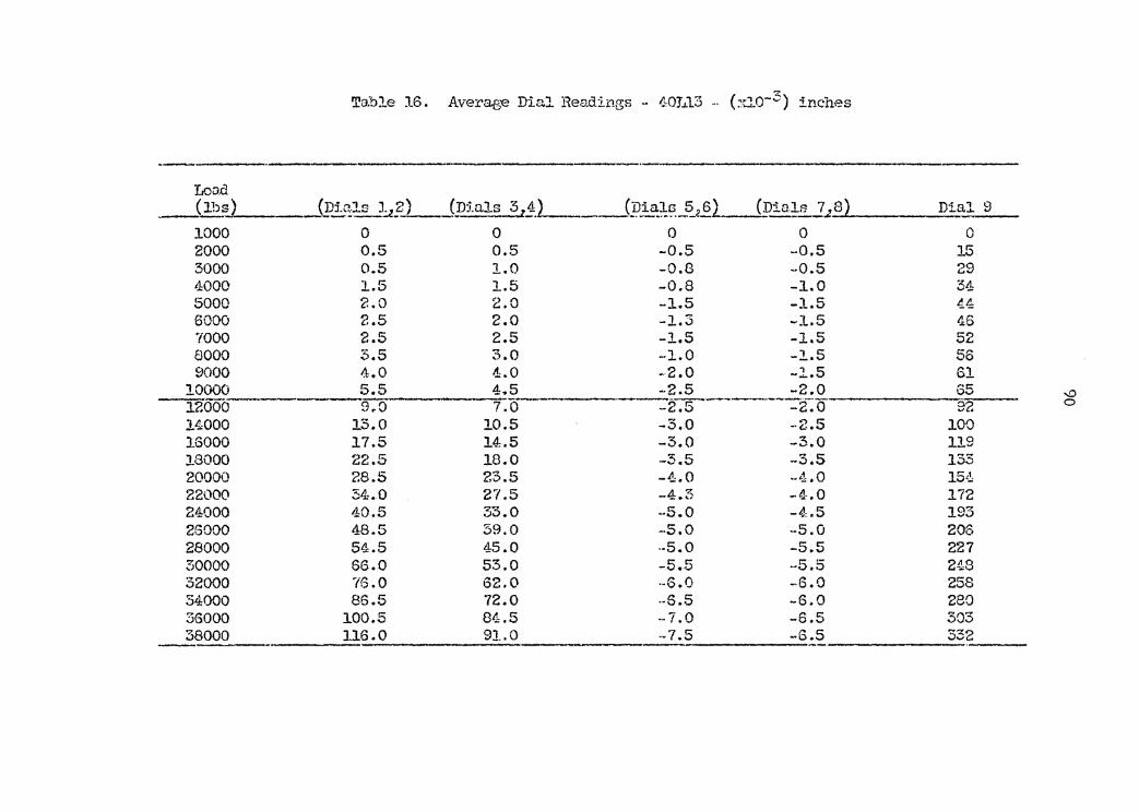
Table 16. Average Dial Headings - .C:OJ.J.13 -· (xio-3) inches
Lood __Jlbs) (pi~ls :1.:.!.?) (p:i.als 3 z2:.L_ __ (pi~;J.;~.-5_._§_l____{pia!s 7.;. 8) Dial 9
1000 0 0 0 0 0 2000 0.5 0.5 -0.5 -0.5 15 3000 0.5 1.0 -0.8 --0.5 29 t.1:000 1.5 l.5 -0.8 -1.0 ~.ll. ...,_ 5000 2.0 2.0 -1.5 -1.5 4.4: 6000 2.5 2.0 -1.3 -1.5 46 ?000 2.5 2.5 -l.5 -1.5 52 8000 3.5 3.0 -1.0 -l.5 56 9000 4.0 4.0 -2.0 -1.5 61
10000 5.5 4.5 -2.5 -2.0 "C:: Ov '° 12000 9.0 7.0- -2. 5 ----·---:-2. 0 92 0
14000 13.0 10.5 -3.0 -2.5 100 16000 17.5 14.5 -3.0 -3..0 119 18000 22.5 18.0 --3.5 -3.5 r~ 00
20000 28.5 23.5 -4.0 .. 4 .o 15,.!: 22000 34.0 27.5 -4.3 -·LO 172 24000 40.5 33.0 -·5.0 -'L5 10~ .,o 26000 48.5 39.0 .. s.o .. s.o 206 28000 54.5 45.0 .. s.o -5.5 227 30000 66.0 53.0 -5.5 -5.5 248 32000 '16 .o 62.0 ·-6.0 -6.0 258 34000 86.5 "72.0 ·-6.5 -6.0 280 36000 100.5 84.5 .. 7. 0 -6.5 303 38000 116.0 91.0 .. 7 .5 .. 5 .5 332
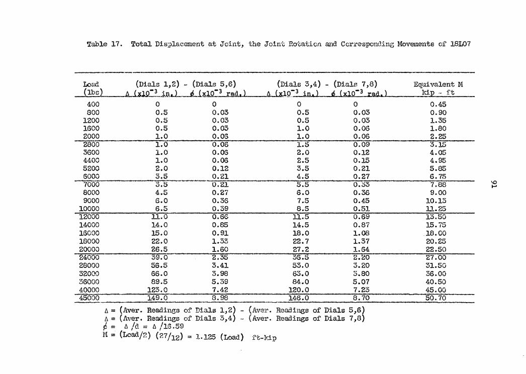
Table 17. Total Displacement at Jcint, the Joint Rotation a.:nd Corresponding Movements of 18L07
Loci..d (Dials 1,2) - (Dials 5,6) (Dia.ls 3,4) - (Dials 7,8) Equivalent M (lbs) ' -3 . J " (xl0-3 rad,) 6. (xJ,._~f" 3 in.) s6 (xl0-3 raQ..) ldp •" ft A iliL:...J.11 ... .. 400 0 0 0 0 0.45 800 0.5 0.03 0.5 0.03 0.90
1200 0.5 0.03 0.5 0.03 1.35 1600 0.5 0.03 1.0 0.06 1.80 2000 1.0 0.06 1.0 0.06 2.25 2800 1.0 0.06 1.5 0.09 3.15 3600 1.0 0.06 2.0 0.12 4.05 4400 1.0 0.06 2.5 0.15 4.95 5200 2.0 0.12 3.5 0.21 5.85 6000 3.5 0.21 4.5 0.27 6.75 7000 5.5 0.21 5.5 0.33 7.88 \0 ..... 8000 4.5 0.27 6.0 0.36 9.00 9000 6.0 0.36 7.5 0.45 10.13
10000 6.5 0.39 8.5 0.51 ll.25 ]2000 11.0 0.66 11.5 0.69 13.50
14000 14.0 0.85 14.5 0.87 15.75 16000 15.0 0.91 18.0 1.08 18.00 18000 22.0 1.33 22.7 1.37 20.25 20000 26.5 1.60 27.2 1.64 22.50 24000 39.0 2.35 36.5 2.20 27.00 28000 56.5 3.41 53.0 3.20 31.50 32000 66.0 3.98 63.0 S.80 36.00 36000 89.5 5.39 84.0 5.07 40.50 40000 123.0 7.42 120.0 7.23 45.00 45000 149.0 8.98 146.0 8.70 50.70
6. = (Aver. Readings of Dials 1,2) - (Aver. Readings of Dials 5,6) b. = (Aver. Readings of Dials 3,4) - (Aver. Readings or Dials 7,8) ~ = b. /d = 6. /lG .59 M= (Lcad/2) (?.7/12) = 1.125 (Loa.a.) ft-ldp
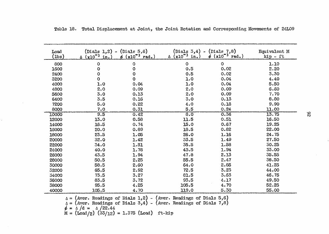
Table 18. Total Displacement at Joint, the Joint Rotation and Corresponding Movements of' 24L09
Load (Dials 1,2) - (Dials 5,6) (Dials 3,4) - (Dials 7,8) Equivalent M (lbs) A (xl0- 3 in.) ~ (xl0- 3 rad.} A (xlo- 3 in.} ~ (xl0- 3 rad.} kip - ft. 800 0 0 0 0 1.10
1600 0 0 0.5 0.02 2.20 2400 0 0 0.5 0.02 3.30 3200 0 0 1.0 0.04 4.40 4000 1.0 0.04 1.0 0.04 5.50 4800 2.0 0.09 2.0 0.09 6.60 5600 3.0 0.13 2.0 0.09 7.70 6400 3.5 0.16 3.0 0.13 8.80 7200 5.0 0.22 4.0 0.18 9.90 8000 7.0 0.3J.. 5.5 0.24 11.00
10000 9.5 0.42 8.0 0.36 13.75 '° I\)
12000 13.0 0.58 11.5 0.51 16.50 14000 16.5 0.74 15.0 0.67 19.25 16000 20.0 0.89 18.5 0.82 22.00 18000 23.5 1.05 26.0 l.16 24.75 20000 32.0 1.42 33.5 1.49 27.50 22000 34.0 1.51 35.5 1.58 30.25 24000 40.0 1. 78 43.5 1.94 33.00 26000 43.5 1.94 47.8 2.13 35.55 28000 50.5 2.25 55.5 2.47 38.50 30000 58.5 2.60 64.0 2.85 41.25 32000 65.5 2.92 72.5 3.23 44.00 34000 73.5 3.27 81.5 3.63 46. 75 36000 83.5 3.72 93.5 4.17 49.50 38000 95.5 4.25 105.5 4.70 52.25 40000 105.5 4.70 ll9.0 5.30 55.00
A= ~Aver. Readings of Dials 1,2~ - (Aver. Readings of Dials 5,6~ A= Aver. Readings of Dials 3,4 - (Aver. Readings of Dia.ls 7,8 p = A Id = A /22. 44 M = (Load/2) (33/12) = 1.375 (Load) f't-ldp
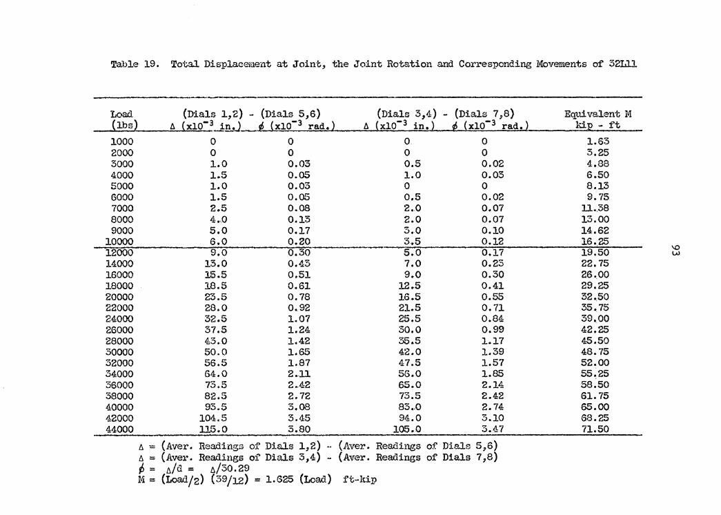
Tal)le 19. Tota.l Displ.a.ceme:nt at Joint, the Joint Rotation and Corresponding Movements of 32Ll1
Load (Dials 1,2) - (Dials 5,6) (Dials 3,4} - (Dials 7,8) Equivalent M (lbs) !>. (xio-3_.J,!l..J ~ {xl0-3 rad.} !>. {xl0-3 in.} ~ {xl0-3 rad.} kiE - f't 1000 0 0 0 0 1.63 2000 0 0 0 0 3.25 3000 1.0 0.03 0.5 0.02 4.88 4000 1.5 0.05 1.0 0.03 6.50 5000 1.0 0.03 0 0 8.13 6000 1.5 0.05 0.5 0.02 9. 75 7000 2.5 0.08 2.0 0.07 ll .. 38 8000 4.,0 0.13 2.0 0.07 13.00 9000 5.0 0.1.7 3.0 0.10 14.62
10000 6.0 0.20 3.5 0.12 16 •. 25 12000 9.0 0.30 5.0 0.17 19.50 '° w 14000 13.0 0.43 7.0 0.23 22.75 16000 15.5 0.51. 9.0 0.30 26.,00 18000 18.5 0.61 12 .. 5 0.41 29.25 20000 23.5 0.78 16.5 0.55 32 •. 50 22000 28.0 0.92 21.s 0.71 35.75 24000 32.5 1.07 25.5 0.84 39.00 26000 37.5 1.24 30.0 0.99 42.25 28000 43.0 1.42 35.5 1.17 45.50 30000 50.0 1.65 42.0 J...39 48. 75 32000 56.5 1.87 47.5 1.57 52.00 34000 64.0 2.11 56.0 1.85 55.25 36000 73.5 2.42 65.0 2.14 58.50 38000 82.5 2.72 73.5 2.42 61. 75 40000 93.5 3.08 83 •. 0 2.74 65.00 42000 104.5 3.45 94.0 3.10 68.25 44000 115.0 3.80 105.0 3.47 71.50
!!. = (Aver. Readings of Dials 1,2) -· (Aver. Readings of Dials 5,6) t;.. = (Aver. Readings of Dials 3,4) - (Aver. Readings of Dials 7,8) p = f!./d = !!./30.29 M = (Load/2) (39/12) = 1.625 (Load} ft-kip

Table 20. Total Displacement at Joint, the Jo1.nt Rotation and Corresponding Movements of 40Ll~
Load (Di~ 1,2) - (Dials 3s,6) (Dial~ 3,4) - (Dials ~,8) Equivalent M __Q.~ 6 (xlO- in.) ~ (xlO~ rad.) 6. (x10- in.) ~ (x16- rad.) kilL:._ft __
1000 0 0 0 0 2.13 2000 1.0 0.02 i .. o 0.02 4.25 3000 1.3 0.03 1.5 0.04 6.38 4000 2.5 0.06 2.5 0.07 8.50 5000 3.5 0.09 3.5 0.09 10.63 6000 s.e 0.10 3.5 0.09 12.75 7000 4.0 O.ll 4.0 O.ll 14.90 8000 4.5 0.12 4.5 0.12 17.00 9000 6.0 0.16 5.5 0.14 19~15
10000 7.8 0.20 s .. s 0.17 21.25 12000 ll.5 0.30 s.o
...... __ 0.24 25 .• 50
'° 14000 16.0 0.42 15.0 0.34 29. 75 ~
1.$000 20.5 0.54 17.5 0.46 34.00 18000 26.0 0.68 21.5 0.56 38.25 20000 32.5 0.85 27.5 0.72 42.50 22000 38.3 1-00 51.5 0.82 46. 75 24000 45.5 1.1.9 37.5 o •. 98 51.00 26000 53.5 J .• -40 44 .. 0 l..:I.-5 55.25 28000 59.S 1.55 50.5 1.32 59 .. 50 30000 71.5 1.87 58.5 1..55 63.75 32000 82.0 2.14 68.0 l.78 68.00 :54000 92~5 2.42 78.0 2.04 72.25 36000 107,5 2.81 91.0 2.38 76.50 38000 123.5 s.22 97A~ 2.54 80.75
b.= ~Aver. Re8.di11gs of Dials 1,2) - -~Aver. ·Re.a.dings of Dials 5,6) 11= Aver. Readings of Dials 3,4) - Aver. Rea.dings of DiaJ.s 7,8) ¢ = 6. /d = /). /38.30 M= (Load/2) (51/12) c 2.l.25 (Load) ft-kip
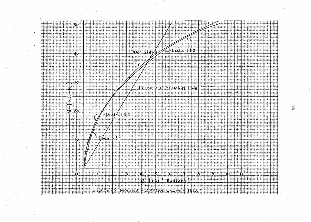
-1 un ~; 1 1 . '.::· ~.: '..~ ... · ~.'.. 1J:: ~.'..·.~.~ ·_~,'. -~ ~-~n i r-r.t. - ~ :-:·;;: l;.:.: ; ··-·· ; •...

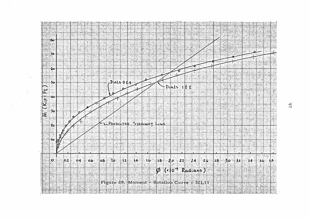
t; ~=-1 i;:: ;_;_t: J'_:.:1 + -~ ~ • -~ I .. ' . • •-! • • ~ ~· •. .. . . ~ . . -. .. ~ ! .•. : L ~ ..;....! .
~. : ......
. ~·1-i n1 ~r:-:_ l_: t:
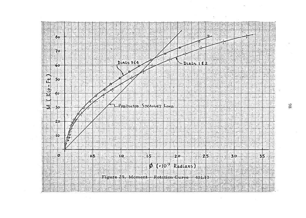


100
VII. DISCUSSION OF RESULTS
From the testing data 1 t is apparent that the proposed connec-
tion behaved as a semi-rigid connection. Observing the moment-
rotation curve of each test section, there is a similar character
between them. That is, the connection passes through three stages:
First, an initlal stage with DlOJllent approximately in proportion to
rotation; Second, a gradual spread of yielding in the connection; and
Third, a stage of accelerated rotation, finally resulting in failure
of the vertical veb member.
A comparison of the predicted values vith the actual values for
moment-rotation relationship is given as follows. From the Z-g1 curve
on page56 9 the predicted value of Z •+/Min inch-kips of 1.05(10-5)
equals 0.126(10-3) in rt-kips. This relationship is plotted on page
96 as a straight line tor longspan joist l8L07. In a similar manner
the predicted values of moment-rotation relationship of the remaining
joists are plotted on pages 97 -99.
Observing the moment-rotation curve in relation to the predicted
straight line, it is obvious that the connection behaves quite stiff'
at small load which is indicated by that the curve is above the
straight line and gradually as the load increases the curve shifts
below the straight line. This is due to the inelastic behavior of
the connection. The instrumentation used was as suggested by ttie
testing done at Lehigh Univereity.6 '
101
VIII. CONCLUSION
The author's conclusion tram the testing is that the proposed
connection is appropriate for semi-rigid connections. This conclu-
sion is based on the observation ot the moment-r~t&tion curves,
vhich vere plotted tram the test data.
There are several points ot interest that the author would like
to see studied further. They are as tollovs:
(1) To desisn a vertical veb member strong enough to develop
the maximum negatiYe moment capacity or each longspan joist.
(2) To observe the behavior of connection at the exc~ssive
yielding range.
(3) To establish the design range of this type or connection
from testin« more connections tor the purpose ot practical design.
(4) To establish the failure load or this type of connection.

102
IX. REFERENCES
1. Bak.er, J. F.; I!!! Steel Skeleton; University Press, Cambridge
University, England; 1954.
2. Maugh, L. C.; StaticaU.y Indeterminate Structures; John Wiley and
Sons, Inc., New York, N. Y.; 1947.
3. Lothera, John E.; Advanced Desip !!!. Structural Steel; Prentice-
Hall, Inc.; Englewood Cliffs, N. J.; 1960.
4. Welch, Richard E.; Semi-Rigid Connections !!!. Trussed Beams;
Thesis; Virginia Po~echnic Institute; 1958.
5. Hechtman, Robert A. and Johnston, Bruce G.; Desisn Economy !?Z,
Connection Restraint; Engineering Neva-Record; Oct. 10, 1940.
6. Hechtman, Robert A. and Johnston, Bruce G.; Riveted Semi-Rigid
Beam to Column Connections; Progress Report No. 1, American - - ---------Institute of Steel Construction; 1948.
7. American Institute of Steel Construction; Manual of Steel .................. _ ............. Construction; pp. 4-48, 49; 1963.
8. Coabs, Carlton E., Jr.; !!!, Initial Stuc\y 2!, Semi-Rigid Connec-
tions; Thesis; Virginia Polytechnic Institute; 1961.
9. Steel Joist Institute; Open Web Steel Construction, 1959 Edition,
Shortapan and Longspan Series.
10. The James F. Lincoln Arc Welding Foundation; Design 2!, Welded
Structural Connections; p. 22.
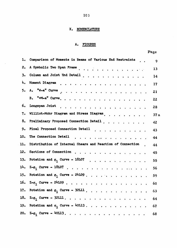
10 3
X. NOMENCLATURE
A. FIGURES
1. Comparison or Moments in Beams of Various End Restraints • • 2. A Symbolic Two Span Frame . . . . . . 3. Column and Joist End Detail
4. Moment Diagram . . 5. A. "w-a" Curve .. . . . .
B. "+M-a" Curve . . . . 6. Longspan Joist . . 7. Williot-Mohr Die.gram and Strese Diagram . . 8. Preliminary Pro~osed Connection Detail . . 9. Final Proposed Connection Detail . .
10. The Connection Detail . . .
Page
9
13
14
17
Zl
Z2
28
37a
4,z
43
44
11. Distribution of Internal Shears and Reaction of Connection 44
12 • Sections or Connection • 45
13. Rotation 8lld s1 CUrve - 18L07 55
14. Z-g1 Curve - l8L07 • 56
15. Rotation and g1 Curve - 24L09 •
16. Z-g1 Curve - 24L09 • • •
17. Rotation and g1 Curve - 32Lll
18. Z-g1 Curve - 32Lll . . • •
19. Rotation and g1 Curve - 40L13 •
20. Z-g1 Curve - 40L13 • •
. .
. . . . .
59
60
63
64 67
68

104
18L07 Test Section . . . . . . . . '! • • • • • . . . 24L09 Teat Section • . . • • . . . . . . .
21.
22.
23.
24.
32Lll Test Section . . . . . . . . . . . . . . . . . 40L13 Teat Section . . . . . . . . . .
25. Set-up of Teat Section • • • . . . . . . . 26. Moment - Rotation CUrve - 18L07 . . . . . . . . 27. Moment - Rotation Curve - 24L09
0 I ' . . . . . . 28. Moment - Rotation CUrve - 32Lll . . . . . . 29. Moment - Rotation Curve - 40Ll3
I O . . . . . . 30. Deflection Curve ot Dials 9 tor all Test Sections . . . . .
Page
74
75
76
77
79
95
96
97
98
99
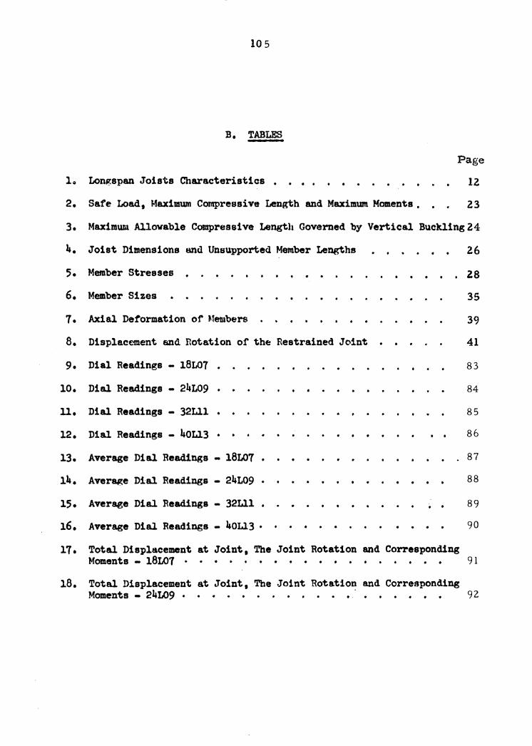
10 5
B. TABLES
Page
Longspan Joists Characteristics • . . . . . 2. Safe Load, Maximum Compressive Length and Maximum Moments • . .
12
Z3
3. Maximum illowable Compressive Length Governed by Vertical Buckling 24
4. Joist Dimensions and Unsupported Member Lengths . . 26
5. Member Stresses • . . . . . . ZS 6. Member Sizes 35
7. Axial Deformation of Members 39
8. Displacement and Rotation of the Restrained Joint • 41
9. Dial Readings - 1BL07 . 83
10. Dial Readings - 24L09 . . 84
u. Dial Readings - 32Lll • . . 85
12. Dial Readings - 40L13 . • • 86
13. Average Dial Readings - 18L07 • . . . . . . . 87
14. Average Dial Readings - 24L09 • . . . . . • 88
15. Average Dial Readings - 32Lll • . . 89
16. Average Dial Readings - 40L13 • . . . . 90
17. Total Displacement at Joint, The Joint Rotation and Corresponding Moments - 18L07 • • • • • • • • • • • • 91
18. Total Displacement at Joint, The Joint Rotation and Corresponding Moments - 24L09 • • • 92

106
Page
190 Total Displacement at Joint. The Joint Rotation and Corresponding Moments - 32Lll 93
20. Total Displacement at Joint 9 The Joint Rotation and Corresponding Momenta - 40L13 94
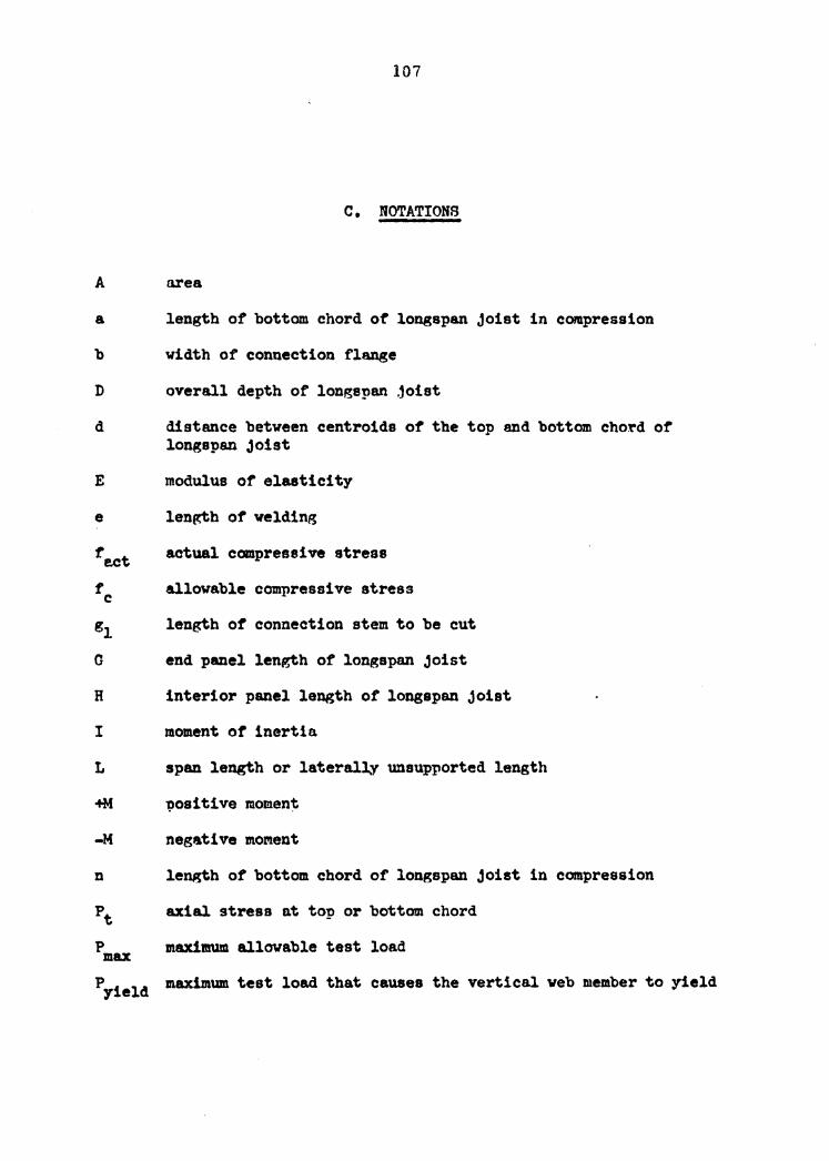
107
c. NOTATIONS
A area
a length of bottom chord of longspan joist in C011lpression
b width of connection flange
D overall depth of longspan .1oist
d distance between centroids of the top end bottom chord ot longspan joist
E modulus or elasticity
e len~h of welding
re.ct actual compressive stress
tc allovable compressive stress
g1 length ot connection stem to be cut
G end panel length of longspan joist
R interior panel length ot longspan joist
I moment ot inertia
L span length or laterally unsupported length
+M ~ositive moment
-M negative mo~ent
n length of bottom chord o~ longspan joist in compression
Pt axial stress at top or bottO!J1 chord
P maximum allowable test load max Pyield maximum test load that causes the vertical web member to yield
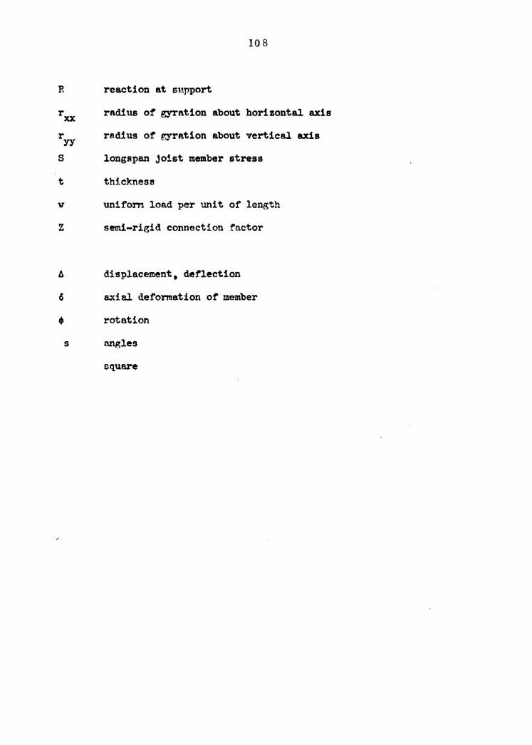
10 8
R .reaction at support
rxx radius of gyration about horizontal axis
r re.di us ot ror-re.tion about vertical axis yy s longspan joist member stress
t tM.ekness
w uniform load per unit of length
z semi-rigid connection factor
~ displacement, deflection
6 axial deformation of member
• rotation
s Nlgles
square

109
D. J'.BBREVIATIONS
be bottom chord
k kips
k-ft kip-foot
klf kips per linear foot
ksi kips per square inch
plt pounds per linear foot
rad radians
tc top chord
110
XI. ACKNOWLEDGMENTS
The author is especially grateful and deeply indebted to
Professor John F. Poulton tor his guidance, patience and inspira-
tion during two years ot graduate studies at Virginia Polytechnic
Institute. His counsel and enlightening suggestions tor writing
this thesis are sincerely appreciated.
Acknowledgment is also made to and
whose assistance in fabricating test sec-
tions was most helpful.
This investigation was made possible by using the laboratory
tacilitiea ot the Department ot Engineering Mechanics at the Virginia
Polytechnic Institute. The author extends his appreciation to the
personnel of the Department tor their interest.

The vita has been removed from the scanned document
ABSTRACT
Frequently in engineering design economy' is sacrif'iced because of
a lack or knowledge ot the behavior or the structure. Because ot the
lack or information on the restraint values ot beam-column connec-
tions, the beam is otten over designed by tailing to take advantage
ot partial continuity. If the degree of restraint ot a beam-column
connection can be determined, the optimum beam moment can be derived
and then an optimum or economic beam can be designed.
This thesis is mainly concerned with the effective analysis and
design ot a particular type ot semi-rigid connection between longspan
joists and columns. It is also an attempt to establish a correct
technic tor testing :f'ull. size longspan joists and column connections.
Although not camnonly utilized in industry, in which longspan
joists most frequently are used as simple-supported beams, the long-
span joists have a degree of' negative moment capacity. It this
negative moment capacity can be utilized, a more efficient and
econanical building frame can be obtained. This thesis is also an
attempt to analyze and determine the magnitude of the desired nega-
tive moment capacity ot tour representative longapan joists. A
proposed semi-rigid connection based on this negative moment capacity
is designed. Then the tull size representative longapan joists are
assembled by the semi-rigid connections to the tull size representa-
tive columns.

The four test sections were fabricated and tested by the author
in the Engineering Mechanic Laboratory at the Virginia Polytechnic
Institute. The tests indicated that the proposed connections vere
quite satisfactory.


![3-D Finite Element Analysis of Semi-rigid Steel Connections [Yarı Rijit Çelik Bağlantıların 3-D Sonlu Elemanlar Ile Analizi]](https://img.pdfslide.net/doc/110x75/577cc8521a28aba711a27daa/3-d-finite-element-analysis-of-semi-rigid-steel-connections-yari-rijit-celik.jpg)