Embed Size (px)
Citation preview

Master thesis
Development of the Detector Control System for
the Muon Forward Tracker at ALICE
Hiroshima University, Graduate School of Science,Department of Physical Science, Quark Physics Laboratory
M154616Kosei Yamakawa
Supervisor: Associate Professor Kenta ShigakiChief Examiner: Associate Professor Kenta ShigakiVice-Examiner: Associate Professor Kenichi Ishikawa
February 24, 2017
Abstract
We have been performing the ALICE experiment to study the nature of the quark-gluonplasma, which is a new state of matter expected by Quantum ChromoDynamics, and tounderstand quark confinement and chiral-symmetry restoration, which is considered as theorigin of hadron mass. After several years of data taking, we defined an upgrade program ofALICE for the LHC Runs 3 and 4. One part of this program is the Muon Forward Tracker(MFT). The MFT should improve the invariant mass resolution and measurement of heavyflavors down to low transverse momenta at the forward pseudo-rapidity.
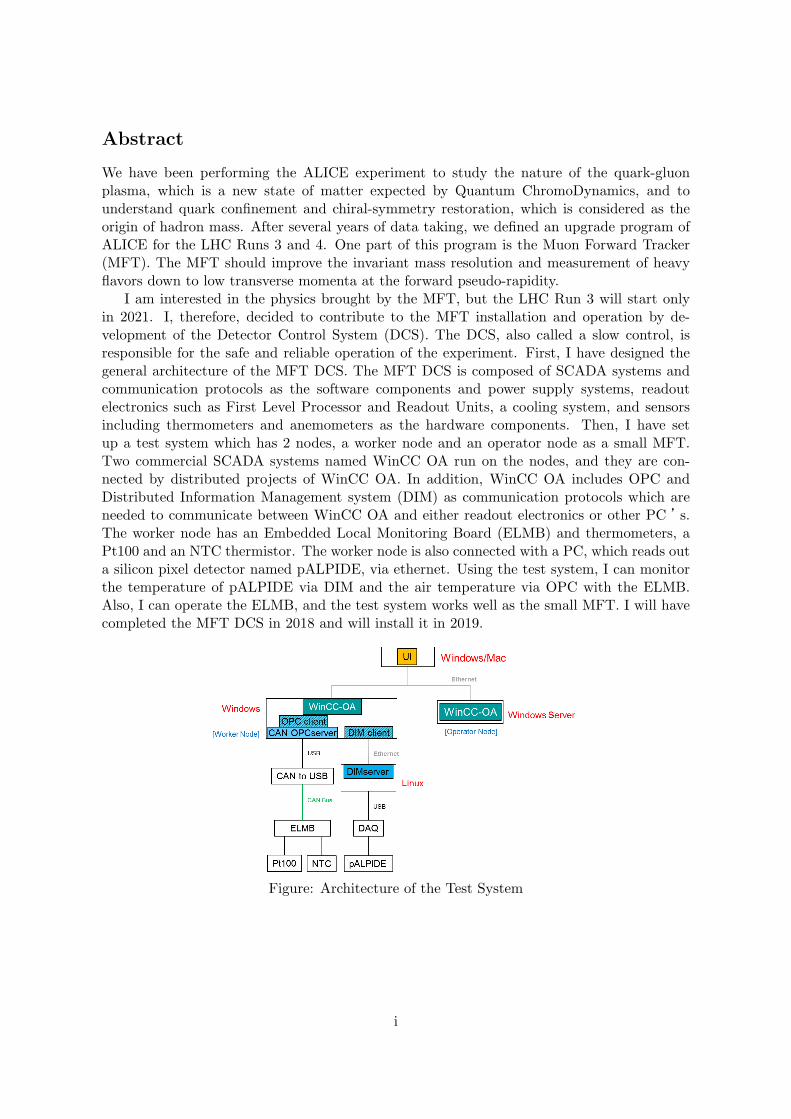
I am interested in the physics brought by the MFT, but the LHC Run 3 will start onlyin 2021. I, therefore, decided to contribute to the MFT installation and operation by de-velopment of the Detector Control System (DCS). The DCS, also called a slow control, isresponsible for the safe and reliable operation of the experiment. First, I have designed thegeneral architecture of the MFT DCS. The MFT DCS is composed of SCADA systems andcommunication protocols as the software components and power supply systems, readoutelectronics such as First Level Processor and Readout Units, a cooling system, and sensorsincluding thermometers and anemometers as the hardware components. Then, I have setup a test system which has 2 nodes, a worker node and an operator node as a small MFT.Two commercial SCADA systems named WinCC OA run on the nodes, and they are con-nected by distributed projects of WinCC OA. In addition, WinCC OA includes OPC andDistributed Information Management system (DIM) as communication protocols which areneeded to communicate between WinCC OA and either readout electronics or other PC ’s.The worker node has an Embedded Local Monitoring Board (ELMB) and thermometers, aPt100 and an NTC thermistor. The worker node is also connected with a PC, which reads outa silicon pixel detector named pALPIDE, via ethernet. Using the test system, I can monitorthe temperature of pALPIDE via DIM and the air temperature via OPC with the ELMB.Also, I can operate the ELMB, and the test system works well as the small MFT. I will havecompleted the MFT DCS in 2018 and will install it in 2019.
Figure: Architecture of the Test System
i

Contents
1 Introduction 11.1 Quark-Gluon Plasma . . . . . . . . . . . . . . . . . . . . . . . . . . . . . . . . . 11.2 Research Background . . . . . . . . . . . . . . . . . . . . . . . . . . . . . . . . 11.3 Object of my study . . . . . . . . . . . . . . . . . . . . . . . . . . . . . . . . . . 2
2 ALICE Upgrade Program 32.1 Overview . . . . . . . . . . . . . . . . . . . . . . . . . . . . . . . . . . . . . . . 32.2 Physics Motivation . . . . . . . . . . . . . . . . . . . . . . . . . . . . . . . . . . 32.3 Detector Upgrade . . . . . . . . . . . . . . . . . . . . . . . . . . . . . . . . . . . 4
2.3.1 Inner Tracking System . . . . . . . . . . . . . . . . . . . . . . . . . . . . 42.3.2 Muon Forward Tracker . . . . . . . . . . . . . . . . . . . . . . . . . . . . 62.3.3 Time Projection Chamber . . . . . . . . . . . . . . . . . . . . . . . . . . 72.3.4 Fast Interaction Trigger . . . . . . . . . . . . . . . . . . . . . . . . . . . 9
2.4 Computing System Upgrade . . . . . . . . . . . . . . . . . . . . . . . . . . . . . 92.4.1 Online-Offline computing system . . . . . . . . . . . . . . . . . . . . . . 9
3 Muon Forward Tracker 113.1 Overview . . . . . . . . . . . . . . . . . . . . . . . . . . . . . . . . . . . . . . . 113.2 Physics Program in Pb-Pb collisions . . . . . . . . . . . . . . . . . . . . . . . . 113.3 Hardware Components of the MFT detector . . . . . . . . . . . . . . . . . . . . 14
4 Detector Control System at ALICE 164.1 Overview of the Detector Control System at ALICE . . . . . . . . . . . . . . . 164.2 DCS Software . . . . . . . . . . . . . . . . . . . . . . . . . . . . . . . . . . . . . 17
4.2.1 SCADA system and WinCC OA . . . . . . . . . . . . . . . . . . . . . . 174.2.2 Joint Control Project Framework . . . . . . . . . . . . . . . . . . . . . . 204.2.3 OPC . . . . . . . . . . . . . . . . . . . . . . . . . . . . . . . . . . . . . . 204.2.4 Distributed Information Management system . . . . . . . . . . . . . . . 21
4.3 DCS Hardware . . . . . . . . . . . . . . . . . . . . . . . . . . . . . . . . . . . . 224.3.1 FRontEnd Device servers . . . . . . . . . . . . . . . . . . . . . . . . . . 224.3.2 First Level Processor . . . . . . . . . . . . . . . . . . . . . . . . . . . . . 234.3.3 ALICE Low-level Frontend Interface . . . . . . . . . . . . . . . . . . . . 234.3.4 Common Readout Unit . . . . . . . . . . . . . . . . . . . . . . . . . . . 234.3.5 Embedded Local Monitoring Board . . . . . . . . . . . . . . . . . . . . . 234.3.6 Giga-Bit Transceiver Project and Components . . . . . . . . . . . . . . 244.3.7 Readout Unit and Board . . . . . . . . . . . . . . . . . . . . . . . . . . 25
4.4 Flow Structure of DCS Data in ALICE Run 3 . . . . . . . . . . . . . . . . . . . 27
5 Design of the MFT DCS and Test System 285.1 Hardware Architecture . . . . . . . . . . . . . . . . . . . . . . . . . . . . . . . . 28
5.1.1 Serial Bus Setting for Regulators Monitoring and Control . . . . . . . . 285.1.2 Options for Readout Electronics . . . . . . . . . . . . . . . . . . . . . . 31
5.2 Software Architecture . . . . . . . . . . . . . . . . . . . . . . . . . . . . . . . . 315.3 Test System . . . . . . . . . . . . . . . . . . . . . . . . . . . . . . . . . . . . . . 31
5.3.1 Test System Architecture and Components . . . . . . . . . . . . . . . . 315.3.2 Test System Setup and Results . . . . . . . . . . . . . . . . . . . . . . . 32
ii

6 Summary and Outlook 36
Acknowledgement 37
References 38
iii
List of Figures
1 Schematic generation mechanism of the QGP . . . . . . . . . . . . . . . . . . . 12 QCD phase diagram [1] . . . . . . . . . . . . . . . . . . . . . . . . . . . . . . . 23 Overview of the ALICE major upgrade . . . . . . . . . . . . . . . . . . . . . . . 34 Comparison of impact parameter resolution with the current ITS (blue) and
with the new ITS (red) [7] . . . . . . . . . . . . . . . . . . . . . . . . . . . . . . 65 Layout of the new ITS [7] . . . . . . . . . . . . . . . . . . . . . . . . . . . . . . 66 Layout of the current Muon system [4] . . . . . . . . . . . . . . . . . . . . . . . 77 Layout of the TPC [8] . . . . . . . . . . . . . . . . . . . . . . . . . . . . . . . . 88 Comparison the assumed spectra with the current TPC (left panel) and with
the new TPC (right panel) [8] . . . . . . . . . . . . . . . . . . . . . . . . . . . . 89 Comparison of the current trigger detector (left) and the upgraded trigger de-
tector (right) [9]. . . . . . . . . . . . . . . . . . . . . . . . . . . . . . . . . . . . 910 Flow structure of O2 computing system . . . . . . . . . . . . . . . . . . . . . . 1011 Strategy of improvement of accuracy with the MFT . . . . . . . . . . . . . . . 1112 Measured inclusive J/ψ production at forward pseudo-rapidity [10] . . . . . . . 1213 Measured J/ψ elliptic flow at forward rapidity [11] . . . . . . . . . . . . . . . . 1214 Elliptic Flow (left panel) and nuclear modification factor (right panel) of muons
from heavy flavour hadrons decay in central Pb-Pb collisions [12] . . . . . . . . 1315 Comparison between the expected low mass spectra without the MFT (MUON)
and with the MFT (MUON + MFT) in central collisions [4] . . . . . . . . . . . 1416 The MFT components . . . . . . . . . . . . . . . . . . . . . . . . . . . . . . . . 1517 Architecture of DCS . . . . . . . . . . . . . . . . . . . . . . . . . . . . . . . . . 1718 Architecture of WinCC OA [14] . . . . . . . . . . . . . . . . . . . . . . . . . . . 1819 Distributed systems in WinCC OA [14] . . . . . . . . . . . . . . . . . . . . . . 1920 Data Point Data Point Element [14] . . . . . . . . . . . . . . . . . . . . . . . . 1921 JCOP framework software components[15] . . . . . . . . . . . . . . . . . . . . . 2122 Architecture of OPC communication . . . . . . . . . . . . . . . . . . . . . . . . 2223 Architecture of DIM[18] . . . . . . . . . . . . . . . . . . . . . . . . . . . . . . . 2224 Diagram of the O2[6] . . . . . . . . . . . . . . . . . . . . . . . . . . . . . . . . . 2325 Diagram of CRU[22] . . . . . . . . . . . . . . . . . . . . . . . . . . . . . . . . . 2426 Block diagram of ELMB[19] . . . . . . . . . . . . . . . . . . . . . . . . . . . . . 2427 Flow structure of GBT[23] . . . . . . . . . . . . . . . . . . . . . . . . . . . . . . 2528 GBT-SCA block diagram[25] . . . . . . . . . . . . . . . . . . . . . . . . . . . . 2629 The architecture of Readout Unit[27] . . . . . . . . . . . . . . . . . . . . . . . . 2630 Structure of DCS data flow . . . . . . . . . . . . . . . . . . . . . . . . . . . . . 2731 Architecture of the MFT DCS . . . . . . . . . . . . . . . . . . . . . . . . . . . 2932 Explanation of the detector drawings, field layer . . . . . . . . . . . . . . . . . 3033 CAEN system diagram [28] . . . . . . . . . . . . . . . . . . . . . . . . . . . . . 3034 Architecture of the test system . . . . . . . . . . . . . . . . . . . . . . . . . . . 3235 Data Point Data Point Element . . . . . . . . . . . . . . . . . . . . . . . . . . . 3236 JCOP framework installation panel . . . . . . . . . . . . . . . . . . . . . . . . . 3337 Temperatures of thermistors connected to the ELMB . . . . . . . . . . . . . . . 3438 JCOP framework installation panel . . . . . . . . . . . . . . . . . . . . . . . . . 3439 The list of services on RUNServer . . . . . . . . . . . . . . . . . . . . . . . . . . 3540 Temperature of the pALPIDE . . . . . . . . . . . . . . . . . . . . . . . . . . . . 35
iv

List of Tables
1 Comparison of the physics current reach and the proposed physics reach [3]. . . 52 Comparison of the current reach with the Muon spectrometer (MUON) and
the proposed upgrade with the Muon spectrometer and the MFT (MUON +MFT). Assuming integrated luminosity is 10nb−1 in central nucleus-nucleuscollisions. [4] . . . . . . . . . . . . . . . . . . . . . . . . . . . . . . . . . . . . . 15
3 MFT Components [5] . . . . . . . . . . . . . . . . . . . . . . . . . . . . . . . . 164 The lists of CAEN supplies we will use[5] . . . . . . . . . . . . . . . . . . . . . 285 List of the serial buses for control and monitoring . . . . . . . . . . . . . . . . . 30
v

1 Introduction
1.1 Quark-Gluon Plasma
Quantum ChromoDynamics (QCD) is a theory to discriminate behaviours of quarks andgluons. Due to the feature of QCD, namely asymptotic freedom, we cannot take out quarksand gluons alone from hadrons at ordinary environment. However, QCD calculations expectquarks and gluons move freely in an extreme high temperature and dense matter (Fig. 1).The heated and dense medium is a new state of matters, and we call the matter Quark-GluonPlasma (QGP).
Figure 1: Schematic generation mechanism of the QGP
There are predictions that critical temperature for phase transition is around 200 MeV(∼ 2× 10¹² K) and the QGP existed at ten micro-seconds from the Big Bang (Fig. 2). Thus,our recognitions of characters of the QGP lead to our knowledges of the early universe. Ultrarelativistic heavy ion collision experiment is the only generation method of the QGP.
1.2 Research Background
We have been performing A Large Ion Collider Experiment (ALICE) to study the natureof QCD and the QGP with the Large Hadron Collider (LHC). There are theories predictsignatures and examinations of the QCD matter, like J/ψ suppression and strangeness pro-duction. For example, the J/ψ suppression, the effective temperature, and the anisotropicflow, the ALICE collaboration has reported as the probes of the QCD medium . However,there remain several essential questions such as the nature of quark confinement and chiralsymmetry restoration, which we consider as the origin of light quark mass. For further exper-imental study of QCD and the dense medium, our needs are high resolution in the transversemomentum and the invariant mass.
Then, we project an upgrade programme of the ALICE equipment in the LHC LongShutdown 2 (LS2) from 2019 to the end of 2020 towards Run 3 from 2021 and Run 4 from 2026[2]. The Inner Tracking System, the Muon Forward Tracker, the Time Projection Chamber,the Fast Interaction Trigger, and the computing system are our major targets of the upgradeplan. Due to precise measurement of low transverse momentum particles with high resolutionby the upgrade, we will be able to challenge the questions above.
1

Figure 2: QCD phase diagram [1]
1.3 Object of my study
Physics with the upgraded ALICE detectors, in particular with the Muon Forward Tracker(MFT), after LS2 is my interest. For example, in-medium energy loss mechanism of heavyflavours and chiral symmetry restoration in low mass dimuon. However, the MFT is produc-tion stage at present, and Run 3 data taking will start in 2021, hence I cannot analyse physicswith the MFT now. I, therefore, decided to contribute to the MFT installation and operationby development of the Detector Control System (DCS) for physics I am interested in.
First, I have to arrange an architecture of the MFT DCS. For the purpose, I have sum-marized a document for a hardware and software structure of the MFT DCS. The documentshows the number and the installation location of all the components used in the MFT controlsystem. The design document follows the form provided by the ALICE DCS team. Also, Ihave set up a test system as a mini MFT with devices and software used in the current ALICEDCS. Thanks to the test system, I can learn technique for the development and installationof the DCS.
2

2 ALICE Upgrade Program
2.1 Overview
The aims of the ALICE experiment, which is focusing on the heavy ion collisions experimentonly in four major LHC experiments (ALICE, ATLAS, CMS, and LHCb), are understandingof the nature of QCD, the properties of the QGP, and the origin of hadrons’ masses. Theresults of Run 1 revealed that the limitations of the current ALICE detectors prevent us fromthe precise measurement, especially in the low transverse momentum (pT) region and the lowinvariant mass part [3]. Also, the LHC accelerator group plans to increase the beam interactionrate up to 50 kHz and the beam luminosity of L = 6 × 1027cm−2s−1 in Pb-Pb collisionsafter the LHC LS2. The proposed collision rate in the LHC Run 3 is a few times largerthan the present readout rate of the ALICE equipment. Therefore, we decided an upgradeprogramme of the ALICE apparatuses including the detectors and the computing systemto further experimental study (Fig. 3). There are other upgrades of readout electronics ofTransition Radiation Detector (TRD), Time Of Flight (TOF), PHoton Spectrometer (PHOS),and Muon spectrometer.
Figure 3: Overview of the ALICE major upgrade
2.2 Physics Motivation
Precise measurements of heavy flavour production, quarkonia production, and dileptons,mainly in low pT region in Run 3 are our plans. I show the physics motivation of the ALICEupgrade.
• Quarkonia
In general, quarkonia, in particular J/ψ, are good probes of the QGP.Nonetheless, our difficulty of explanation of suppression pattern of ψ(2S) re-
3

quires other models. There are the statistical hadronization model and thekinetic transport model as proposed models.
The statistical model considers charm quarks thermalize in the dense QCDmatter and hodronize at chemical freeze out. The amount of charm quarks isa key parameter of this statistical theory, hence we must measure the produc-tion cross section of charm quarks with high precision to test this theoreticalmodel. On the other hand, the kinetic transport model proposes recombina-tion of charm quarks in the QGP as charm quarks production mechanism.The production yields and elliptic flow are crucial observables for testing thekinetic model.
• Heavy Flavours
There are two major topics, which are thermalization and energy lossmechanism in the QGP, related to heavy quarks measurement. These topicsare particularly close each other.
In the current understanding, heavy flavours lose their energy in the densemedium, and they thermalize participate in the elliptic flow. Actually, we havemeasured the non zero flow of D meson. However, the energy loss mechanismof heavy quarks is not known well. Theories propose collisional energy lossand radiative energy loss are the mechanisms of quarks in the QCD matter.Also, they consider partons lose their energy by radiative mechanism, in otherwords gluons radiation, mainly.
• Dileptons
There is a QCD prediction that the chiral symmetry breaking is the originof hadrons. The theoretical prediction is that there is the chiral symmetryrestoration in the high temperature matter, hence the masses of light vectormesons, especially ρmeson, shift lower mass. For lower mass shift observation,we need high resolution in the low invariant mass region.
We consider the spectrum of real direct photon is a probe of the sourcetemperature. By measurement of dileptons at 0.15 < Mee < 0.3 GeV/c2
and pT > 1 GeV/c, we can measure the direct photon spectrum as the QGPtemperature.
Table 1 shows the comparison of the current physics reach and the proposed physics reach.
2.3 Detector Upgrade
Here, I introduce the overview of the important detector upgrades.
2.3.1 Inner Tracking System
The Inner Tracking System (ITS) covering the central pseudo-rapidity is a detector for trackingand particle identification (PID) of charged particles in Runs 1 and 2. There are the sixlayers, the two Silicon Pixel Detectors (SPD), the two Silicon Drift Detector (SDD) and thetwo Silicon Strip Detectors (SSD) from the most inner layer. The impact parameter accuracyof the ITS is enough for the production measurement of charm mesons at pT > 1 GeV/c.However, the performance of the present system is short for the precise measurement of them
4
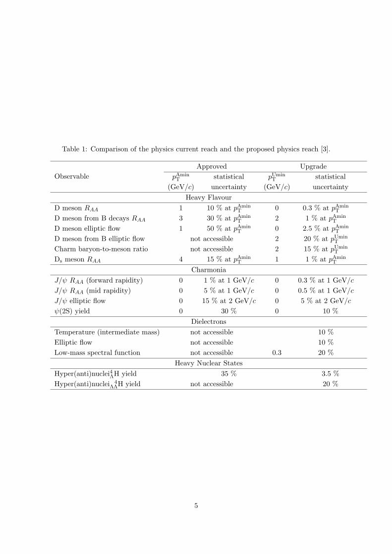
Table 1: Comparison of the physics current reach and the proposed physics reach [3].
Observable
Approved Upgrade
pAminT statistical pUmin
T statistical
(GeV/c) uncertainty (GeV/c) uncertainty
Heavy Flavour
D meson RAA 1 10 % at pAminT 0 0.3 % at pAmin
T D meson from B decays RAA 3 30 % at pAmin
T 2 1 % at pAminT
D meson elliptic flow 1 50 % at pAminT 0 2.5 % at pAmin
T D meson from B elliptic flow not accessible 2 20 % at pUmin
T Charm baryon-to-meson ratio not accessible 2 15 % at pUmin
T Ds meson RAA 4 15 % at pAmin
T 1 1 % at pAminT
Charmonia
J/ψ RAA (forward rapidity) 0 1 % at 1 GeV/c 0 0.3 % at 1 GeV/c J/ψ RAA (mid rapidity) 0 5 % at 1 GeV/c 0 0.5 % at 1 GeV/c J/ψ elliptic flow 0 15 % at 2 GeV/c 0 5 % at 2 GeV/c ψ(2S) yield 0 30 % 0 10 %
Dielectrons
Temperature (intermediate mass) not accessible 10 % Elliptic flow not accessible 10 % Low-mass spectral function not accessible 0.3 20 %
Heavy Nuclear States
Hyper(anti)nuclei4ΛH yield 35 % 3.5 %
Hyper(anti)nuclei 4ΛΛH yield not accessible 20 %
5

at lower pT, because the proper decay length of the charm baryons (∼ 60µm) is shorterthan the impact parameter resolution of the ITS [7]. The capability of the current apparatusprevents us to study beauty mesons and hadrons for the same reason. In addition, the readoutrate of 1 kHz in nucleus-nucleus collisions causes of the above problems.
The main subject of the ITS upgrade is improvements of the impact parameter resolutionand tracking performance by material budget reduction. To reduce material budget, wewill use Monolithic Active Pixel Sensors (MAPS) in the ITS detectors. Thus, the impactparameter resolution of the new ITS will increase as shown in Fig. 4. Moreover, the readoutrate also will increase up to 100 kHz in Pb-Pb collisions and up to 400 kHz in pp collisions.Three Inner Barrel layers (IB) and four Outer Barrel layers (OB) compose the upgraded ITS,and the OB separates into two middle layers and two outer layers (Fig. 5).
Impact parameter resolutionin transverse plane
Impact parameter resolutionin longitudinal plane
Figure 4: Comparison of impact parameter resolution with the current ITS (blue) and withthe new ITS (red) [7]
Figure 5: Layout of the new ITS [7]
2.3.2 Muon Forward Tracker
The Muon spectrometer of ALICE covers at the forward pseudo-rapidity of 2.5 < η < 4 (Fig.6). The main object of the spectrometer muons tracking, and we have studied the quarkonia
6

production, the open heavy flavours production and the low mass dimuons with the detector.However, the multiple scattering of muons in the front absorber causes inaccuracy of theinteraction points, accordingly the current equipment cannot show the full potential. Forexample, it is difficult for us to reject muons coming from semi-muonic decays of pions andkaons at low pT and to distinguish prompt and displaced J/ψ production.
Figure 6: Layout of the current Muon system [4]
To solve the problem, we suggested the Muon Forward Tracker (MFT) in the upgradeprogramme. The strategy of the MFT is that the MFT disks will track charged particle froman interaction point before incoming the front absorber [4]. I will show the details of the MFTproject in Section 3.
2.3.3 Time Projection Chamber
A Time Projection Chamber (TPC) is a detector for charged particles tracking and PID.The information from the TPC plays an important role at ALICE and will provides keyobservables in the proposed programme. Besides, readout systems of the current TPC areMulti-Wire Proportional Chamber (MWPC) based readout chambers. The operation modeof the existing TPC readout chambers is Gating Grid mode, which prevents back-drifting ionsfrom the amplification region of a MWPC to enter the drifting volume. However, the gatedoperation of the MWPC based readout systems effects the limitation of the readout rate of3.5 kHz.
For TPC operation at 50 kHz, we will replace MWPC based chambers with Gas ElectronMultiplier (GEM) based readout systems. We can operate the GEM system with continuousreadout at a collision rate of 50 kHz, thus we will be able to analyse physics observables wecould not access previously. Fig. 8 shows a comparison the assumed e+e− invariant massspectra with the current TPC and with the upgraded TPC in Pb-Pb collisions at
√sNN = 5.5
TeV. Furthermore, the estimated number of recorded events with the improved TPC is abouttwo orders of magnitude more than that of events with the present TPC in a typical yearlyheavy ion run of about 3 nb−1.
7

Figure 7: Layout of the TPC [8]
Figure 8: Comparison the assumed spectra with the current TPC (left panel) and with thenew TPC (right panel) [8]
8
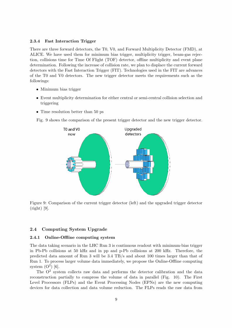
2.3.4 Fast Interaction Trigger
There are three forward detectors, the T0, V0, and Forward Multiplicity Detector (FMD), atALICE. We have used them for minimum bias trigger, multiplicity trigger, beam-gas rejec-tion, collisions time for Time Of Flight (TOF) detector, offline multiplicity and event planedetermination. Following the increase of collision rate, we plan to displace the current forwarddetectors with the Fast Interaction Trigger (FIT). Technologies used in the FIT are advancesof the T0 and V0 detectors. The new trigger detector meets the requirements such as thefollowings:
• Minimum bias trigger
• Event multiplicity determination for either central or semi-central collision selection andtriggering
• Time resolution better than 50 ps
Fig. 9 shows the comparison of the present trigger detector and the new trigger detector.
Figure 9: Comparison of the current trigger detector (left) and the upgraded trigger detector(right) [9].
2.4 Computing System Upgrade
2.4.1 Online-Offline computing system
The data taking scenario in the LHC Run 3 is continuous readout with minimum-bias triggerin Pb-Pb collisions at 50 kHz and in pp and p-Pb collisions at 200 kHz. Therefore, thepredicted data amount of Run 3 will be 3.4 TB/s and about 100 times larger than that ofRun 1. To process larger volume data immediately, we propose the Online-Offline computingsystem (O2) [6].
The O2 system collects raw data and performs the detector calibration and the datareconstruction partially to compress the volume of data in parallel (Fig. 10). The FirstLevel Processors (FLPs) and the Event Processing Nodes (EPNs) are the new computingdevices for data collection and data volume reduction. The FLPs reads the raw data from
9

the detectors via GBT links, and they decrease the data volume by zero cluster finder andbaseline collection. The EPNs receive the data from the FLPs, and the EPNs squeeze thedata amount by online tracking and reconstruction for each detector. Only reconstructed dataare carried in the storage. The O2 also provides the framework which we need for simulationand analysis.
Figure 10: Flow structure of O2 computing system
10

3 Muon Forward Tracker
3.1 Overview
The results of the ALICE Run 1 declared that the multiple scattering of muon in the hadronabsorber affected muon spectra larger than the estimations. The Muon spectrometer providedus the large interaction point in Run 1, thus we cannot study the low mass dimuon productionand heavy flavours production precisely, especially in the low pT region. In the same reason,we have measured the production cross section of inclusive muons from c and b quarks fromlower limited pT. To overcome the problems, we plan to install the MFT.
The main subject of the MFT is an improvement of an accuracy of an interaction point. Toachieve this purpose, the location of the MFT detector is between the absorber and interactionpoint. As a result, the MFT can track charged particles before coming into the absorber (Fig.11).
Figure 11: Strategy of improvement of accuracy with the MFT
The MFT covers the pseudo-rapidity range of −3.6 < η < −2.45. That range is smallerthan the pseudo-rapidity region of the Muon spectrometer of −4 < η < −2.5, because of thebeam pipe.
3.2 Physics Program in Pb-Pb collisions
Thanks to the MFT installation, we will be able to analyse the physics that we cannot studybefore the Run 3. Our physics motivations with the MFT and the Muon spectrometer aremeasurements of open heavy quarks, quarkonia, and low mass dimuons in heavy-ion collisions.I will introduce the physics programme of the MFT in heavy-ion collisions, and Table 2presents the comparisons of the current and the suggested observables.
• Quarkonia
In order to measure the production of prompt J/ψ, we need to remove theinformation of the QGP and b hadrons decay J/ψ. For the goal, we need toseparate prompt and non-prompt J/ψ.
We have measured inclusive J/ψ RAA at forward rapidity in lead-leadcollisions at
√sNN = 2.76 TeV (Fig. 12) [10]. The result is consistent that of
CMS in the high pT region, but RAA measured at PHENIX is more suppressedcompared to ALICE’s result in low transverse momentum. In the transportmodels, charm quarks recombination in dense matter generates about halfamount of J/ψ in the low pT region.
11

Figure 12: Measured inclusive J/ψ production at forward pseudo-rapidity [10]
Also, we have measured elliptic flow of inclusive J/ψ in Pb-Pb collisions at√sNN = 2.76 TeV, the data are consistent with two transport models (Fig. 13)
[10]. The models include J/ψ regeneration about 30 % of the measured J/ψ.In addition, the theoretical calculations drawn in full line and dash-dotted linecount J/ψ from b hadrons decay . There are few differences between thesecalculations. To explain the J/ψ generation models, we need to take moreprecision data for accuracy measurement.
Figure 13: Measured J/ψ elliptic flow at forward rapidity [11]
Moreover, the MFT will provide a possibility that we measure the ψ(2s)production and its RAA as a function of pT. The production mechanism of ψ′
will test the statistical hadronisation model.Besides, we plan to measure the bottomonium production such as Υ(1S)
down to pT of 0 GeV/c. ATLAS and CMS have reported Upsilon productionmeasurement. However, the muon pT threshold of 3 GeV/c makes hardermeasurement in low pT region at ATLAS and CMS. Measurement of Upsilonproduction in the low transverse momentum part is an important subject.
12

• Open Heavy Flavours
The MFT will allow us to detach charm and bottom quarks. Because ofdisentanglement of heavy flavours, we will improve the understanding of theenergy loss mechanism of heavy quarks in the dense QCD matter with theMFT.
We still don’t understand the energy loss mechanism of charm and beautyquarks in the dense medium well. Theoretical prediction of parton energyloss mechanisms is there are radiative energy loss and collisional energy loss.Also, theorists predict Landau-Pomeranchuk-Migdal effect or dead cone effect,however no experiment explores the energy loss mechanism.
The other motivation is elliptic flow. It seems to us that v2 gives informa-tion of collective expansion and thermalization of heavy flavours in the densemedium at pT < 2-3 GeV/c. Flow at 3 GeV/c < pT < 6 GeV/c is a sensitiverecombination process of heavy quarks. Furthermore, flow at pT > 6 GeV/csuppresses the path length dependence of parton energy loss in the QGP.
We have reported inclusive muons RAA and v2 from heavy quarks hadronat forward pseudo-rapidity (Fig. 14). We have been able to measure onlyRAA above transverse momentum region of 4 GeV/c and v2 above transversemomentum range of 3 GeV/c, hence it is difficult for us to compare our resultsand the theories. Therefore, it is necessary that precise measurements of in-medium energy loss of heavy quarks to test the theories.
Figure 14: Elliptic Flow (left panel) and nuclear modification factor (right panel) of muonsfrom heavy flavour hadrons decay in central Pb-Pb collisions [12]
• Low mass dimuons
The MFT should improve the resolution of the low mass dimuon spectrumand the signal over background ratio compared to that with only the Muonspectrometer (Fig. 15). We will be able to challenge the important problemsof QCD with the MFT.
There is a theoretical prediction that there is chiral symmetry restoration,which we believe as the origin of hadrons, in the high temperature matter.However, no experiment has observed the chiral symmetry restoration.
13

Left panel: Dimuon spectrum with only the Muon spectrometerRight panel: Dimuon spectrum with the MFT and the Muon spectrometer
Figure 15: Comparison between the expected low mass spectra without the MFT (MUON)and with the MFT (MUON + MFT) in central collisions [4]
Similarly, we can measure the temperature of QGP using dimuon invariantmass and pT spectra. It appears that dileptons in the invariant mass spectrumat 1.5-2.5 GeV/c2 come from thermal radiation at the early stage of the QGP.Production process of virtual photons is same that of real photons, hence wecan assume virtual photon spectrum using the extrapolation of the dileptonmeasurement in the low or intermediate mass regions.
3.3 Hardware Components of the MFT detector
The MFT detector consists of two half MFTs, an upper half and a lower half, and both ofthe half MFTs are the same structure. The half MFT is composed of a Power Supply Unit(PSU) and five half disks. A half disk is divided into two half planes, a front side and a backside. Three half disks, numbered 0, 1 and 2, have ladders, also, two half disks, numbered 3and 4, have ladders, DC-DC converters and GBT-SCAs each. The PSU comprises DC-DCconverters and GBT-SCAs, since half disks 0, 1 and 2 are too limited to have them. Then,a zone is a cluster of ladders, for example, a zone of half disk 0 consists three ladders, andvoltages are applied zone by zone. A ladder consists of ALICE Pixel DEtector (ALPIDE)chips. Figure 11 shows the components of the MFT, and Table 3 presents the total amountof the MFT components.
14
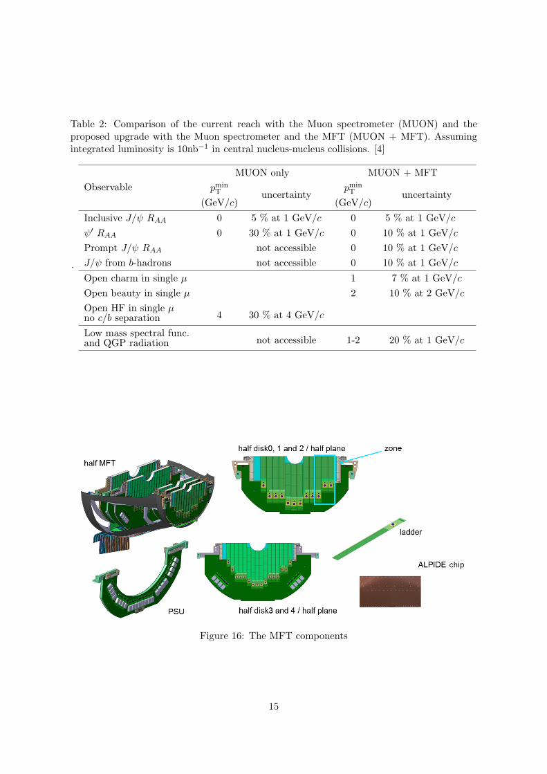
Table 2: Comparison of the current reach with the Muon spectrometer (MUON) and theproposed upgrade with the Muon spectrometer and the MFT (MUON + MFT). Assumingintegrated luminosity is 10nb−1 in central nucleus-nucleus collisions. [4]
.
Observable
MUON only MUON + MFT
pminT uncertainty
pminT uncertainty
(GeV/c) (GeV/c)
Inclusive J/ψ RAA 0 5 % at 1 GeV/c 0 5 % at 1 GeV/c
ψ′ RAA 0 30 % at 1 GeV/c 0 10 % at 1 GeV/c
Prompt J/ψ RAA not accessible 0 10 % at 1 GeV/c
J/ψ from b-hadrons not accessible 0 10 % at 1 GeV/c
Open charm in single µ 1 7 % at 1 GeV/c
Open beauty in single µ 2 10 % at 2 GeV/c
Open HF in single µ4 30 % at 4 GeV/cno c/b separation
Low mass spectral func.not accessible 1-2 20 % at 1 GeV/cand QGP radiation
Figure 16: The MFT components
15

Table 3: MFT Components [5]
Item Total Amount
MFT 1
Half MFT 2
Half Disk 10
PSU 2
Half Plane 20
Zone 80
Ladder 280
Chip 920
4 Detector Control System at ALICE
4.1 Overview of the Detector Control System at ALICE
There are the ALICE detectors in the cave at about 50 meters underground and we cannotgo there due to radioactivity during collisions. No one can come to the cavern, therefore,we must operate and monitor the experimental equipment remotely. The Detector ControlSystem (DCS), also called slow control, allows us to control and supervise the experimentalapparatuses from the ALICE control room at LHC Point2. For example, we can configurethe applied voltage of detectors and monitor the status of them with the DCS. Also, whena temperature of a device is higher than the expected working temperature, a finite statemachine or an interlock system will stop the detector. In other words, the DCS is responsiblefor safe and reliable operation of the experiment.
The DCS consists of three layers which are the supervision layer, the process managementlayer and the field management layer (Figure 17). The supervision layer is in the ALICEcontrol room, and it has graphical user interfaces provided by SCADA systems. The processmanagement layer is in the counting room between the control room and the cavern, andit consists of computing systems, including SCADA system and communication protocolssuch as OPC and DIM. Also, controllers such as Programmable Logic Controllers (PLCs) andpower supply systems are included in the process management layer. SCADA systems connectthe supervision layer and the process management layer via ethernet. Buses called USB orCANbus connect the computing systems in the process management layer and controllersor Power Supply systems (PSs). Then, the field management layer is in the cave, and it iscomposed of field buses, nodes, sensors, and readout electronics. The field management layeralso contains detector setups. Cables for power supply system connect the equipment andthe PSs, and cables such as GBT link (see Section 4.3.6) connect the readout electronics andeither controllers or readout electronics.
16

Figure 17: Architecture of DCS
4.2 DCS Software
4.2.1 SCADA system and WinCC OA
Supervisory Control And Data Acquisition (SCADA) system is one of the industrial controlsystems and used for system operation and process monitoring [13]. Experts in the fields ofpower plants, manufacturing lines and system for the prevention of disasters use the SCADAsystems. WinCC Open Architecture (WinCC OA) is one of the commercial SCADA systemmanufactured by ETM.
There are six components on WinCC OA as follows [14];
• Runtime database
Data from devices are saved in the runtime database. We can visualize andprocess them by accessing the database.
• Archive
WinCC OA users can store the data in the runtime database for a long timeand extract by the user interface and other processes.
• Alarm generation & handling
When some kind of error which is defined by DCS experts happen, WiCC OAwill generate alarms. Alarms are archived in an alarm database, and displayedon an alarm display.
• Graphical editor
Thanks to graphical editor, we can build graphical user interfaces and otherpanels.
• Scripting language
A scripting language named CTRL (called control) is used in WinCC OA,and it allows us to handle the data which are in the database from graphicaluser interfaces.
17
• Graphical parametrization tool
Owing to graphical parametrization tool, we can define the structure of thedatabase and select the data which should be stored and etc.
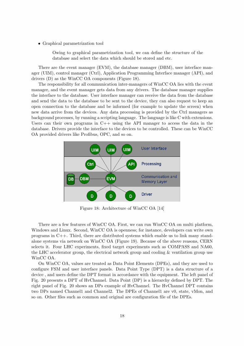
There are the event manager (EVM), the database manager (DBM), user interface man-ager (UIM), control manager (Ctrl), Application Programming Interface manager (API), anddrivers (D) as the WinCC OA components (Figure 18).
The responsibility for all communication inter-managers of WinCC OA lies with the eventmanager, and the event manager gets data from any drivers. The database manager suppliesthe interface to the database. User interface manager can receive the data from the databaseand send the data to the database to be sent to the device, they can also request to keep anopen connection to the database and be informed (for example to update the screen) whennew data arrive from the devices. Any data processing is provided by the Ctrl managers asbackground processes, by running a scripting language. The language is like C with extensions.Users can their own programs in C++ using the API manager to access the data in thedatabase. Drivers provide the interface to the devices to be controlled. These can be WinCCOA provided drivers like Profibus, OPC, and so on.
Figure 18: Architecture of WinCC OA [14]
There are a few features of WinCC OA. First, we can run WinCC OA on multi platform,Windows and Linux. Second, WinCC OA is openness; for instance, developers can write ownprograms in C++. Third, there are distributed systems which enable us to link many stand-alone systems via network on WinCC OA (Figure 19). Because of the above reasons, CERNselects it. Four LHC experiments, fixed target experiments such as COMPASS and NA60,the LHC accelerator group, the electrical network group and cooling & ventilation group useWinCC OA.
On WinCC OA, values are treated as Data Point Elements (DPEs), and they are used toconfigure FSM and user interface panels. Data Point Type (DPT) is a data structure of adevice , and users define the DPT format in accordance with the equipment. The left panel ofFig. 20 presents a DPT of HvChannel. Data Point (DP) is a hierarchy defined by DPT. Theright panel of Fig. 20 shows an DPs example of HvChannel. The HvChannel DPT containstwo DPs named Channel1 and Channel2. The DPEs of Channel1 are v0, state, vMon, andso on. Other files such as common and original are configuration file of the DPEs.
18

Figure 19: Distributed systems in WinCC OA [14]
Example architecture of a Data Point Type
The example architecture of Data Point
Figure 20: Data Point Data Point Element [14]
19

4.2.2 Joint Control Project Framework
For reduction of the cost and manpower for developing control systems in four LHC exper-iments, CERN IT/CO group has developed Joint COntrol Project Framework (JCOP Fw)[15]. This framework is based on WinCC OA projects, and it runs on WinCC OA only. UsingJCOP Fw, users can operate CAEN power supplies, Embedded Local Monitor Board (ELMB)and other devices.
The DCS experts use the following tools, mainly;
• Device Editor and Navigator
Device Editor and Navigator is a main interface of JCOP Fw. Users can con-figure and operate the devices using it. In addition, it includes configurationof finite state machines.
• Trending Tool
When users monitor temperatures and humidity, trending tool visualize theparameters.
• DIM Manager
DIM is a CERN’s original communication protocol, and it is one of the mostimportant parts of the DCS architecture. The DIM manager provides a DIMclient to exchange data with a server,thus users can set the data as DPs.
• Component Installer
Since JCOP Fw is a CERN’s unique framework, DCS experts need to installJCOP Fw on WinCC OA. The users can choose frameworks which users wantto install with the installer.
Figure 21 shows the framework software components. In this figure, PVSS mean a SCADAsystem, and it is former WinCC OA.
4.2.3 OPC
OPC is the standard for safe and trusted exchange of data in industrial automation and otherfields [16]. A lot of commercial devices employ OPC protocol, for example power supplysystems produced by CAEN. To use OPC communication, the OPC foundation which isresponsible for the development and maintenance of this standard must certificate deviceswhich users will use.
There are two specifications in the OPC standard, the OPC Classic and the OPC UnifiedArchitecture (OPC UA). The OPC Classic is separated into three specifications, the OPCData Access (OPC DA), the OPC Alarms & Events (OPC AE), and the OPC HistoricalData Access (OPC HDA).
• OPC DA
The OPC DA specification defines the exchange of values, time and quality.General activities of the OPC DA are update of data which includes param-eters of time and quality.
20

Figure 21: JCOP framework software components[15]
• OPC AE
The OPC AE specification characterizes the exchange of state values, statemanagement, alarms and event types.
• OPC HDA
The OPC HDA specification defines the methods to historical data and timed-stamp data.
• OPC UA
The OPC UA is unified of all OPC Classic specifications.
In the current DCS, we use the OPC DA for communication, however, the ALICE DCSteam plan to use the OPC UA from the Run 3.
For the OPC communication, DCS experts need devices which are certificated by the OPCfoundation, and PC which has an OPC server and OPC clients such as WinCC OA (Figure22). OPC clients do not access to devices for getting data directly, but they get data via OPCserver. OPC servers are published by manufactures which produce devices users will use.
4.2.4 Distributed Information Management system
Distributed Information Management system (DIM) is a communication protocol as same asOPC, and CERN produced it [18]. DIM consists of servers, clients, and DIM Name Servers(DNSs) (Figure 22).
Servers and clients exchange “services”, and a service is a set of data which are any typeor size. Servers register the services to a name server, and servers publish services to clients.By asking a name server at startup, clients subscribe to services, furthermore servers publishand update the services automatically either at regular times or the condition change. Then,
21

Figure 22: Architecture of OPC communication
users can operate the equipment which is connected to a PC which has a DIM server via aDIM client.
Figure 23: Architecture of DIM[18]
OPC is a reliable communication protocol, however, devices need the OPC foundationcertifications. On the other hand, DIM is a CERN’s original communication protocol andfree for use. Therefore, DIM is used for communication between WinCC OA and handmadedevices mainly.
4.3 DCS Hardware
4.3.1 FRontEnd Device servers
For DCS communication, the ALICE DCS group will install FRontEnd Device servers (FREDs)in the counting room [21]. FREDs receive DCS commands from WinCC OA and translatesthem to the native language of CRUs and forwards them to ALFs. In addition, they receivedata from ALF and send them to WinCC OA.
22

4.3.2 First Level Processor
First Level processors (FLPs) will be computing nodes and collect data from detectors ata rate of 3.4 TB/s. FLPs will compress the data, including DCS data from detectors by afactor of six and send physics data to Event Processing Nodes (EPNs). FLPs and FREDswill communicate with each other via network (Fig. 24)
Figure 24: Diagram of the O2[6]
4.3.3 ALICE Low-level Frontend Interface
ALICE Low-level Frontend (ALF) will be an interface and enable us to access to the readoutcards and detectors, also its lightweight server will run on the FLPs. Due to ALFs, we can readand write registers and monitor thorough regularly published data on WinCC OA. FREDsand ALFs will communicate directly for sending DCS commands and DCS data each other.
4.3.4 Common Readout Unit
Common Readout Unit (CRU) is an interface on an FLP between detector readout electronicsand DCS electronics which are ALF and FRED. Field Programmable Gate Array (FPGA)is the base of the CRUs, thus experts can develop CRUs detector specific. For reductionof the size of data, CRUs will perform clustering and background subtraction. As for theMFT DCS, CRUs will strip the data stream from ALPIDEs which will include physics dataand their status such as temperature and applied voltage. CRUs will communicate front-endelectronics of detectors via GBT links.
4.3.5 Embedded Local Monitoring Board
For the purposes of the detector control and monitoring, the ATLAS experiment developedEmbedded Local Monitoring Boards (ELMBs) [19].It can be put on the frontend electronics
23

Figure 25: Diagram of CRU[22]
or a general purpose motherboard.The block diagram of the ELMB is shown in Figure 26. There are 18 general purpose
I/O, 8 digital inputs and 8 digital outputs on the ELMB. It can also have 16 bit ADC andmultiplexing for 64 analog inputs optionally.
Figure 26: Block diagram of ELMB[19]
The ELMB on an mother board is powered via CAN and needs power of 20 mA at 5.5 V.Also, the ELMBs and PCs are connected by CAN-bus, but PCs which do not have CAN-busports need a CAN to USB modules.
4.3.6 Giga-Bit Transceiver Project and Components
It is said that particle physics will avail enormous amount of data transmitted from experi-mental equipment at high luminosity. To deal the data, we will require readout electronicswhich have wide bandwidth compared with the current. Also, they are going to be requiredto be radiation-tolerant. As for ALICE, it is expected that the amount of readout data ofRun 3 will be about 100 times larger than those of Run 1. The Giga-Bit Transceiver (GBT)project has started to produce components that satisfy these requirements [23].
24

Figure 27 shows the concept of GBT. There are four components, a trans-impedanceamplifier (GBTIA), a laser driver (GBTLD), a transceiver (GBTX) and a slow control adapter(GBT-SCA). Mean of “Slow Control” in Figure 27 is same that of the DCS.
Figure 27: Flow structure of GBT[23]
Here, I introduce the components needed for the development of the DCS.
• GBTX
The GBTX is a flexible link interface chip and responsible for high speedbidirectional optical link, and its bandwidth is 3.2 - 4.8 Gb/s [24]. It managesthe communication between in the counting room receiver and transmitterand the front end module on detectors. For Timing and Trigger Control,Data Acquisition (DAQ), and Slow Control, the GBTX provides three paths,and a single optical link combines these paths as shown in Figure 27. Thanksto the GBTX, we will be able to avail readout data, trigger data, timingcontrol distribution, slow control, and monitoring simultaneously.
• GBT-SCA
The GBT-SCA is an ASIC for detector operation and their environmentalmonitoring. On the GBTX, the GBT-SCA connects to e-port by bidirectionallink, called e-link, and e-link runs at 40 MHz double data rate mode, givingan effective data rate of 80 Mbps [25].
Figure 28 shows the block diagram of the GBT-SCA. There are 1 I2C mas-ters, 1 SPI master, 1 JTAG master, 32 general I/O as bidirectional interfaceports, and it also includes 31 analog inputs multiplexed to 12 bit ADC and 4analog outputs controlled by 4 independent 8 bit DACs on the GBT-SCA.
4.3.7 Readout Unit and Board
The MFT readout electronics is composed of the Readout Units (RUs) for the connected pixelsensors control and monitoring and receive data [26]. The RU board has FPGAs, GBTXs,and a GBT-SCA to interface with ALICE O2 and with the central trigger processor via GBTlinks, and the board process all detector data including physics data and DCS data (Fig. 29).The RUs will be located at about 5 meters distant from the MFT, and cables manufacturedby Twinax connect the RU boards and the MFT.
25
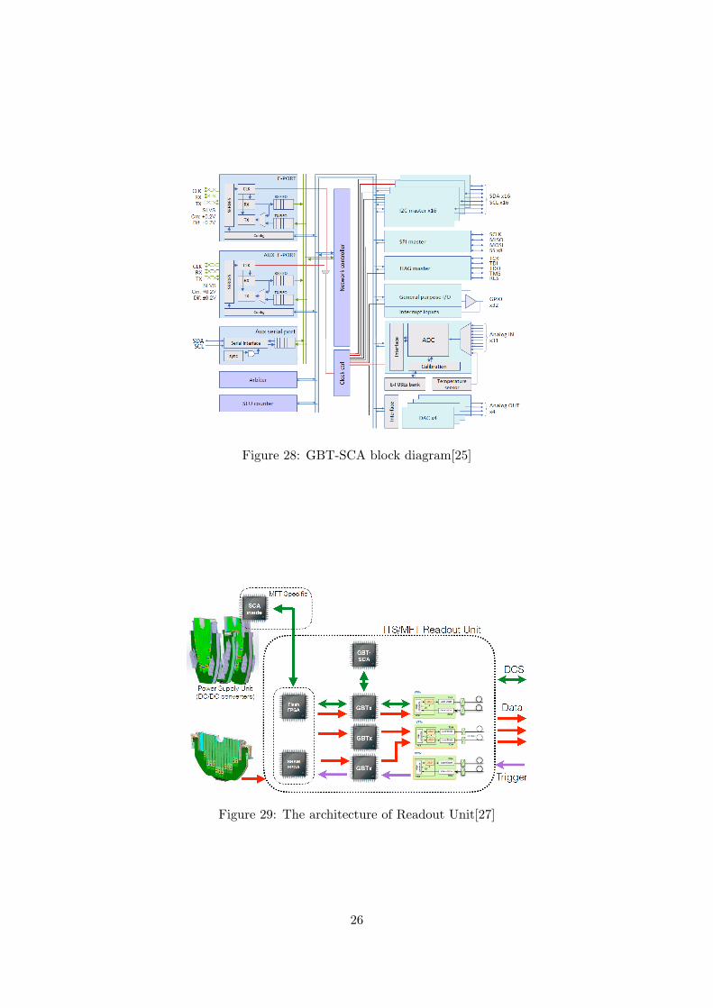
Figure 28: GBT-SCA block diagram[25]
Figure 29: The architecture of Readout Unit[27]
26

4.4 Flow Structure of DCS Data in ALICE Run 3
The DCS archives the data in the DCS database after each period of collisions, called run,for offline analysis in Runs 1 and 2 [21]. In Run 3, the O2 project plans to take and processdata simultaneously, therefore, the DCS needs to send about 100,000 values to FLPs in 20 mstime frames.
The O2 includes the DCS as a part of the project. Therefore, the ALICE DCS needs theelectronics meet requirement of the O2, the FRED and the ALF. DCS data, commands andstatus, are translated into CRUs’ language for smooth shipping with them. Figure 30 showsthe data flow structure of the DCS. The words “control” mean DCS data, including DCScommands, and “Data stream” include physics data and the status of detectors.
Figure 30: Structure of DCS data flow
27

5 Design of the MFT DCS and Test System
5.1 Hardware Architecture
The three layers compose the MFT DCS as same as the ALICE DCS. The supervision layerconsists of only a part of power supply unit. The process management layer contains fourworker nodes, an operator node, power supply system, and the O2 and DCS electronics. Thefield management layer has GBT-SCAs, RU crates, RU boards, DC-DC converters, Low DropOut (LDO) regulators, ALPIDEs, and thermometers. LDO regulator plays a role as same as aDC-DC converter, but we call LDO regulator which has small difference between input voltageand output voltage. Fig. 31 shows the general architecture of the MFT DCS. I followed theexplanation of the detector drawing (Fig. 32) to make the diagram.
In Fig. 31, the left node shows the power supply systems for DC-DC converters andLDOs. The DC-DC converters supplies the power the zones, and the LDO regulators supplythe bias voltage to ALPIDEs. Low Voltage (LV) means voltages for the silicon pixel chips inthe field of high energy physics. We will operate the CAEN family as the LV power supplysystem (Table 4). We can control the EASY systems only via A1676A branch controllers (Fig.33). We will use LDO regulators of MIC39152 manufactured by Micrel for bias voltages ofALPIDEs. Also, we will handle DC-DC converters of DC-DC module FEASTMP CLP fromCERN.
Table 4: The lists of CAEN supplies we will use[5]
Model Type Description
SY4527 Crate Universal multichannel power supply systemA1676A Controller Branch controller for the EASY systemA3486 Power Supply 48V power supply for the EASY systemEASY3000 Crate Magnetic field and radiation tolerant crate for hostile areaA3009 Board 12 channel 8 V / 9 A / 45 W power supply boardA2519 Board 8 channel 15V/5 A (50 W) individual floating channel board
The second left means a power supply system for five RU crate and eighty RU boards.However, the system is not defined, so “PS” means power supply are written. The secondfrom right works for control and monitoring of ALPIDEs, DC-DC converters, LDOs and theirtemperatures via RUs.
The right node is a cooling system. We will use Programmable Logic Controllers (PLCs)produced by SIEMENS as cooling plant controllers.
5.1.1 Serial Bus Setting for Regulators Monitoring and Control
From the GBT-SCAs, we will configure and monitor DC-DC converters and LDOs. Table 5shows the list of serial buses on the GBT-SCA for monitoring and control.
On the CRUs, data from the ALPIDEs are stripped into physics data and DCS data.Therefore, we design to read the status of ALPIDEs from CRUs.
28

Figure 31: Architecture of the MFT DCS
29

Figure 32: Explanation of the detector drawings, field layer
Figure 33: CAEN system diagram [28]
Table 5: List of the serial buses for control and monitoring
Device Serial Bus
DC-DC Converters’ ON/OFF I/ODC-DC Converters’ applied voltage monitoring ADCCooling Block Temperature I2C
30

5.1.2 Options for Readout Electronics
There are two options for the readout electronics of the MFT DCS. One is with GBT-SCAs,and the other is with ELMBs.
Option A GBT-SCA
As I mentioned earlier, the GBT-SCAs are new devices for the DCS fromCERN. The O2 systems need that adapters. Therefore, I take into considera-tion as a primary solution. However, the GBT project team is developing it,so I cannot test a test system with a GBT-SCA.
Option B ELMB
The ELMB is a traditional device for the DCS, and we have used them forthe current ALICE DCS. Therefore, I take into consideration it as a backupsolution of the MFT DCS.
5.2 Software Architecture
The software architecture of the MFT DCS consists of two layers, the supervision layer andthe process management layer. There is a user interface in the supervision layer. An operatornode and four worker nodes compose the process management layer. WinCC OA runs on allof them, and WinCC OA on the operator node provides the user interface. The worker nodefor the LV supply has CAEN OPC server, and the worker node for the RU power supply hasthe OPC server produced by a manufacture which produces power supply system we will use.The worker node for the equipment control and monitoring will communicate with FRED viaDIM. FSM will run on the operator node.
5.3 Test System
I have set up a test system with an ELMB as a small MFT. The system includes almostneeded skills for the MFT DCS with the ELMBs. I will show the architecture of the testsystem and results.
5.3.1 Test System Architecture and Components
The test system consists of an operator node, a worker node, and a user interface (Fig. 34).The worker node is a detector part of the small MFT, and the operator node is a computingpart of it. WinCC OA runs on both of the nodes, and distributed projects of WinCC OAconnect the nodes each other.
The worker node has the ELMB and two thermometers, a Pt100 and a Negative Temper-ature Coefficient (NTC) thermistor. Pt100 is a resistance thermometer, and NTC thermistoris a semiconductor thermometer. It is also connected to a Linux PC, which reads out apALPIDE, via ethernet, and the OS is Cern CentOS 7 (CC7). WinCC OA on the workernode contains an OPC client and a DIM client. The worker node also has an OPC server toread out values from the ELMB. A DIM server and a DNS server run on CC7 for sending ser-vices to the DIM client and receiving commands from the client. Control and monitoring aredone from the user interface, which is connected to the operator node via Windows RemoteDesktop.
31

Figure 34: Architecture of the test system
5.3.2 Test System Setup and Results
First, I created the environment for the DCS with the ELMB. WinCC OA version of 3.11 wasdownloaded from the CERN engineering department page(https://wikis.web.cern.ch/wikis/display/EN/PVSS+Service+Download+3.11SP1), and in-stalled it on the nodes. I made a distributed project on each node, and I confirmed thatthe nodes are connected each other (Fig. 35).
Distributed system panelon the operator node
Distributed system panelon the worker node
Figure 35: Data Point Data Point Element
Next, I got the JCOP framework version 5.2.1 from CERN(https://wikis.web.cern.ch/wikis/display/EN/JCOP+Framework) and installed frameworkson both the worker node and the operator node using the installation panel. I selectedthe frameworks named AbalogDigital, BarGraph, Caen, ConfigurationDB, Core, DIM, FSM-ConfDB, Trending, and XML (Fig. 36). The right window in Fig 36 shows the installedframework components.
Next, I obtained a CAN OPC server and a JCOP framework component for the ELMBfrom the ATLAS ELMB Documentation and Framework Component page(https://twiki.cern.ch/twiki/bin/view/Atlas/DcsElmb). To use OPC, I wrote an OPC con-
32
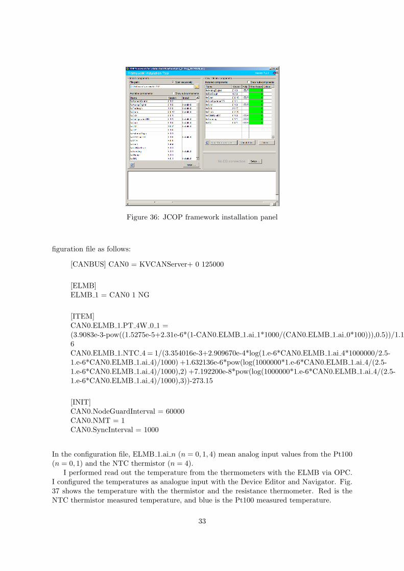
Figure 36: JCOP framework installation panel
figuration file as follows:
[CANBUS] CAN0 = KVCANServer+ 0 125000
[ELMB]ELMB 1 = CAN0 1 NG
[ITEM]CAN0.ELMB 1.PT 4W 0 1 =(3.9083e-3-pow((1.5275e-5+2.31e-6*(1-CAN0.ELMB 1.ai 1*1000/(CAN0.ELMB 1.ai 0*100))),0.5))/1.155e-6CAN0.ELMB 1.NTC 4 = 1/(3.354016e-3+2.909670e-4*log(1.e-6*CAN0.ELMB 1.ai 4*1000000/2.5-1.e-6*CAN0.ELMB 1.ai 4)/1000) +1.632136e-6*pow(log(1000000*1.e-6*CAN0.ELMB 1.ai 4/(2.5-1.e-6*CAN0.ELMB 1.ai 4)/1000),2) +7.192200e-8*pow(log(1000000*1.e-6*CAN0.ELMB 1.ai 4/(2.5-1.e-6*CAN0.ELMB 1.ai 4)/1000),3))-273.15
[INIT]CAN0.NodeGuardInterval = 60000CAN0.NMT = 1CAN0.SyncInterval = 1000
In the configuration file, ELMB 1.ai n (n = 0, 1, 4) mean analog input values from the Pt100(n = 0, 1) and the NTC thermistor (n = 4).
I performed read out the temperature from the thermometers with the ELMB via OPC.I configured the temperatures as analogue input with the Device Editor and Navigator. Fig.37 shows the temperature with the thermistor and the resistance thermometer. Red is theNTC thermistor measured temperature, and blue is the Pt100 measured temperature.
33

Figure 37: Temperatures of thermistors connected to the ELMB
For DIM communication, I added the DIM manager, named WCCOAdim, as followingconfiguration (Fig. 38):
Options: -num 2 -dim dns node DELL C221.hepl.hiroshima-u.acjpStart mode: Manual
Figure 38: JCOP framework installation panel
JCOP DIM plays a role of a DIM client, so I don’t need install DIM software on the workernode.
I downloaded a DIM software from the CERN DIM page (http://dim.web.cern.ch/dim/)and installed it on the CC7 for the DIM communication. I configured the name of DNSserver as same as the CC7 host name “DELL C221.hepl.hiroshima-u.ac.jp”. Also, I set theDIM sever named “RUNServer” for pALPIDE temperature monitoring. DIM server sendsthe temperature to DIM client on the worker node.
I can also read the temperature of pALPIDE via DIM just like the thermometers via OPC.Fig. 40 presents the pALPIDE temperature on WinCC OA.
I have completed the test system as the small MFT with the ELMB and the pALPIDE.
34

Figure 39: The list of services on RUNServer
Figure 40: Temperature of the pALPIDE
35

6 Summary and Outlook
I have designed the general architecture of the MFT DCS. Mainly, I have summarised thenumber and the location of the MFT DCS items. Also, I have set up the test system, and thestructure of the test system is as same as the current ALICE DCS.
In 2017 spring, prototypes of GBT-SCA and CRU will be completed and I will get them.Consequently I will install them in the test system, also I will try to read the pALPIDE statuswith them. By the end of 2017, I will install a ladder in the test system, and build the testbench at CERN. The plan of the MFT installation is in 2019, thus we need to complete beforethe MFT installation. Thus, I will complete the MFT DCS in 2018.
36

Acknowledgement
I would like to thank my supervisor and a convenor of the MFT work package 7 Associateprofessor K.Shigaki. He gave me the dissertation theme and advices for the architecture of theMFT DCS. I acknowledge all stuffs in Hiroshima University, Professor T.Sugitate, Assistantprofessor K.Homma, and Assistant professor T.Miyoshi for their useful comments. Also, Iexpress my gratitude towards P.Chochula, O.Pinazza, and the other members of the ALICEDCS group. Not only they gave me helpful advices and comments, but also they lent methe ELMB setup for the test system. And I acknowledge K.Oyama for his practical opinions,including suggestions to points I did not pay attention to. I also thank A.Nobuhiro for hiscomments and help with pALPIDE readout, and I could not build the test without his advices.
37

References
[1] J. Schaffner-Bielich, Signals of the QCD Phase Transition in the Heavens,Proceedings of Science, CPOD07:062,2007
[2] Longer term LHC schedule, https://lhc-commissioning.web.cern.ch/lhc-commissioning/schedule/LHC-long-term.htm, accessed on 22 Dec, 2016
[3] B. Abelev et al., Upgrade of the ALICE Experiment: Letter Of Intent,J. Phys. G 41 (2014) 087001
[4] ALICE Collaboration, Addendum of the Letter Of Intent for the Upgrade of the ALICEExperiment : The Muon Forward Tracker, CERN-LHCC-2013-014
[5] ALICE Collaboration, Technical Design Report for the Muon Forward Tracker, CERN-LHCC-2015-001
[6] ALICE Collaboration, Technical Design Report for the Upgrade of the Online-OfflineComputing System, CERN-LHCC-2015-00
[7] ALICE Collaboration, Technical Design Report for the Upgrade of the ALICE InnerTracking System, J. Phys. G 41 (2014) 087002
[8] ALICE Collaboration, Technical Design Report for the Upgrade of the ALICE TimeProjection Chamber, CERN-LHCC-2013-020
[9] ALICE Collaboration, Upgrade of the ALICE Readout & Trigger System, CERN-LHCC-2013-019
[10] Christophe Suire for the ALICE Collaboration, Charmonia production in ALICE,Nuclear Physics A 910911 (2013) 106113
[11] ALICE Collaboration, J/Ψ Elliptic Flow in Pb-Pb Collisions at√sNN = 2.76 TeV,
Phys. Rev. Lett. 111, 162301 (2013)
[12] ALICE Collaboration, Elliptic flow of muons from heavy-flavour decays at forward ra-pidity in Pb-Pb Collisions at
√sNN = 2.16 TeV, Phys. Lett. B 753 (2016) 41
[13] Softech, Development of SCADA, http://www.softech.co.jp/scada main.htm
[14] The LHCb collaboration, PVSS Introduction for Newcomers, https://lhcb-online.web.cern.ch/lhcb-online/ecs/PVSSIntro.htm
[15] M. Gonzalez-Berges on behalf of the Framework Team, The Joint COntrols ProjectFramework, arXiv:physics/0305128
[16] OPC Foundation, https://opcfoundation.org
[17] CERN OPC Support , https://wikis.web.cern.ch/wikis/display/EN/OPC+Support
[18] C. Gaspar et al., DIM, http://dim.web.cern.ch/dim/
[19] B. Hallgren et al., The Embedded Local Monitor Board (ELMB) in the LHC Front-endI/O Control System, 7th Workshop on Electronics for LHC Experiments, Stockholm,Sweden, 10 - 14 Sep 2001, pp.325-330 (CERN-2001-005)
38

[20] J. R. Cook and G. Thomas, ELMB123 Documentation,https://edms.cern.ch/ui/file/684947/LAST RELEASED/ElmbUserGuide.pdf
[21] P. Chochula et al., The Evolution of The ALICE Detector Control System, Proceedingsof ICALEPCS2015, Melbourne, Australia
[22] F. Costa, CRU Firmware Overview, The 7th ALICE ITS Upgrade, MFT, and O2 AsianWorkshop, https://indico.cern.ch/event/484521/contributions/2239343/attachments/1316434/1972117/CRU Firmware Overview.pdf
[23] K. Wyllie et al., A Gigabit Transceiver for Data Transmission in Future High EnergyPhysics Experiments, Physics Procedia 37 (2012) 1561
[24] GBT Project Team, GBTX Manual Draft V0.15, https://espace.cern.ch/GBT-Project/GBTX/Manuals/gbtxManual.pdf
[25] A. Caratelli et al., The GBT-SCA, a radiation tolerant ASIC for detector control andmonitoring applications in HEP experiments, Journal of Instrumentation 10 (2015)C03034
[26] K.M. Sielewicz et al., Prototype readout electronics for the upgraded ALICE InnerTracking System, 2017 JINST 12 C01008
[27] R. Tieulent, MFT needs for detector tests, The 8th ALICE ITS Upgrade, MFT, andO2 Asian Workshop, https://indico.cern.ch/event/578890/contributions/2391065/attachments/1382606/2102600/Tieulent MFT O2 Needs.pdf
[28] CAEN, Technical Information Manual, http://www.caen.it/servlet/checkCaenManualFile?Id=10067
39