Embed Size (px)
Citation preview
Mastercam 2017 Tray Jewelry Box Page 39-1
Jewelry Box
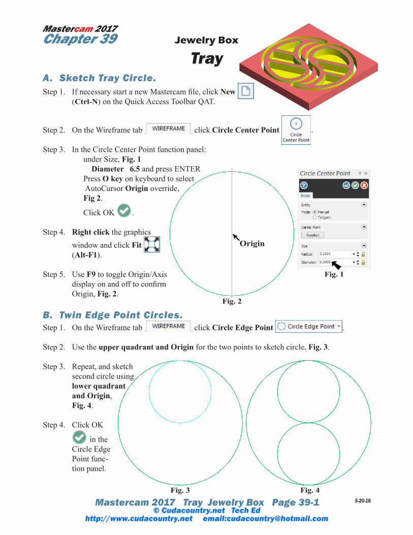
Tray A. Sketch Tray Circle. Step 1. If necessary start a new Mastercam file, click New
(Ctrl-N) on the Quick Access Toolbar QAT.
Step 2. On the Wireframe tab click Circle Center Point .
Step 3. In the Circle Center Point function panel: under Size, Fig. 1 Diameter 6.5 and press ENTER Press O key on keyboard to select AutoCursor Origin override, Fig 2.
Click OK .
Step 4. Right click the graphics window and click Fit (Alt-F1).
Step 5. Use F9 to toggle Origin/Axis display on and off to confirm Origin, Fig. 2.
B. Twin Edge Point Circles. Step 1. On the Wireframe tab click Circle Edge Point .
Step 2. Use the upper quadrant and Origin for the two points to sketch circle, Fig. 3.
Step 3. Repeat, and sketch second circle using lower quadrant and Origin, Fig. 4.
Step 4. Click OK
in the Circle Edge Point func-tion panel.
5-20-16
Mastercam 2017Chapter 39
Fig. 2
Fig. 4Fig. 3
Origin
Fig. 1
© Cudacountry.net Tech Edhttp://www.cudacountry.net email:[email protected]
Mastercam 2017 Tray Jewelry Box Page 39-2
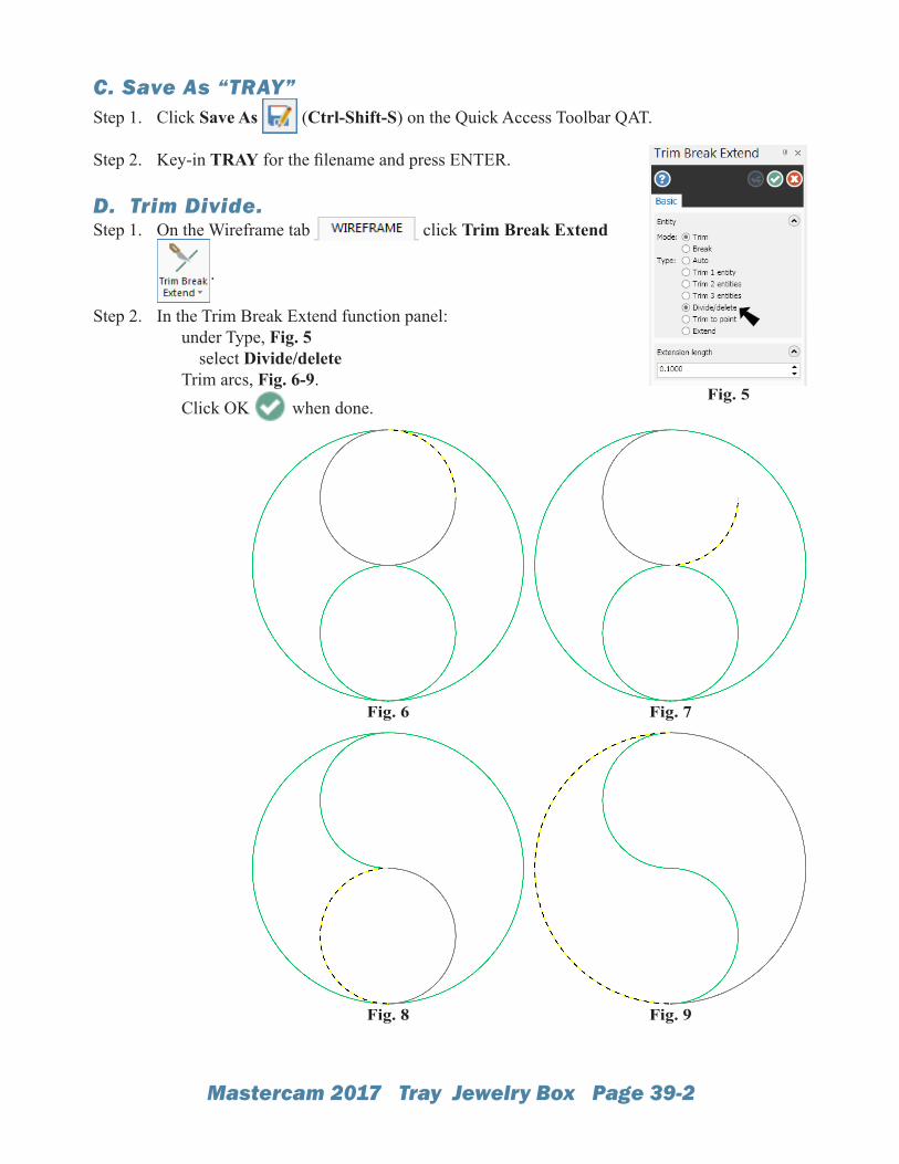
C. Save As “TRAY”Step 1. Click Save As (Ctrl-Shift-S) on the Quick Access Toolbar QAT.
Step 2. Key-in TRAY for the filename and press ENTER.
D. Trim Divide.Step 1. On the Wireframe tab click Trim Break Extend
.
Step 2. In the Trim Break Extend function panel: under Type, Fig. 5 select Divide/delete Trim arcs, Fig. 6-9. Click OK when done.
Fig. 7Fig. 6
Fig. 9Fig. 8
Fig. 5
Mastercam 2017 Tray Jewelry Box Page 39-3
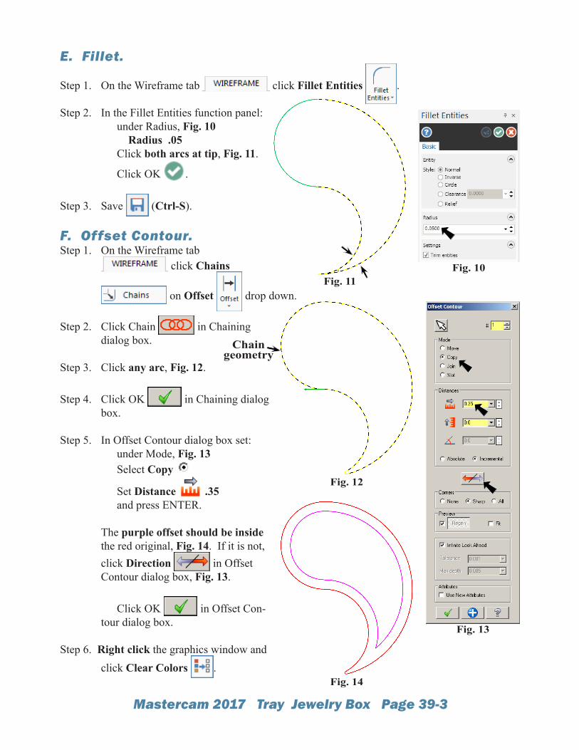
E. Fillet.
Step 1. On the Wireframe tab click Fillet Entities .
Step 2. In the Fillet Entities function panel: under Radius, Fig. 10 Radius .05 Click both arcs at tip, Fig. 11.
Click OK .
Step 3. Save (Ctrl-S).
F. Offset Contour.Step 1. On the Wireframe tab
click Chains
on Offset drop down.
Step 2. Click Chain in Chaining dialog box.
Step 3. Click any arc, Fig. 12.
Step 4. Click OK in Chaining dialog box.
Step 5. In Offset Contour dialog box set: under Mode, Fig. 13 Select Copy
Set Distance .35 and press ENTER. The purple offset should be inside the red original, Fig. 14. If it is not, click Direction in Offset Contour dialog box, Fig. 13.
Click OK in Offset Con-tour dialog box.
Step 6. Right click the graphics window and click Clear Colors .
Fig. 11Fig. 10
Fig. 13
Fig. 12
Fig. 14
Chain geometry
Mastercam 2017 Tray Jewelry Box Page 39-4
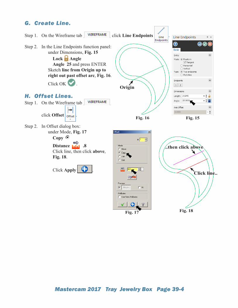
G. Create Line.
Step 1. On the Wireframe tab click Line Endpoints .
Step 2. In the Line Endpoints function panel: under Dimensions, Fig. 15 Lock Angle Angle 25 and press ENTER Sketch line from Origin up to right out past offset arc, Fig. 16.
Click OK .
H. Offset Lines.Step 1. On the Wireframe tab
click Offset .
Step 2. In Offset dialog box: under Mode, Fig. 17 Copy
Distance .8 Click line, then click above, Fig. 18. Click Apply .
Fig. 17 Fig. 18
Click line..
..then click above
Fig. 15Fig. 16
Origin
Mastercam 2017 Tray Jewelry Box Page 39-5
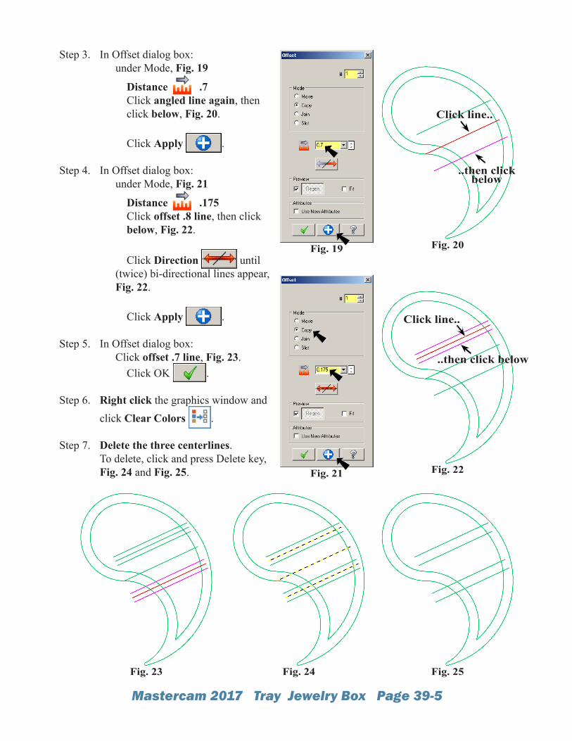
Step 3. In Offset dialog box: under Mode, Fig. 19
Distance .7 Click angled line again, then click below, Fig. 20. Click Apply .
Step 4. In Offset dialog box: under Mode, Fig. 21
Distance .175 Click offset .8 line, then click below, Fig. 22. Click Direction until (twice) bi-directional lines appear, Fig. 22.
Click Apply .
Step 5. In Offset dialog box: Click offset .7 line, Fig. 23. Click OK .
Step 6. Right click the graphics window and click Clear Colors .
Step 7. Delete the three centerlines.To delete, click and press Delete key, Fig. 24 and Fig. 25.
Fig. 19 Fig. 20
Click line..
..then click below
Fig. 21 Fig. 22
Click line..
..then click below
Fig. 25Fig. 24Fig. 23
Mastercam 2017 Tray Jewelry Box Page 39-6
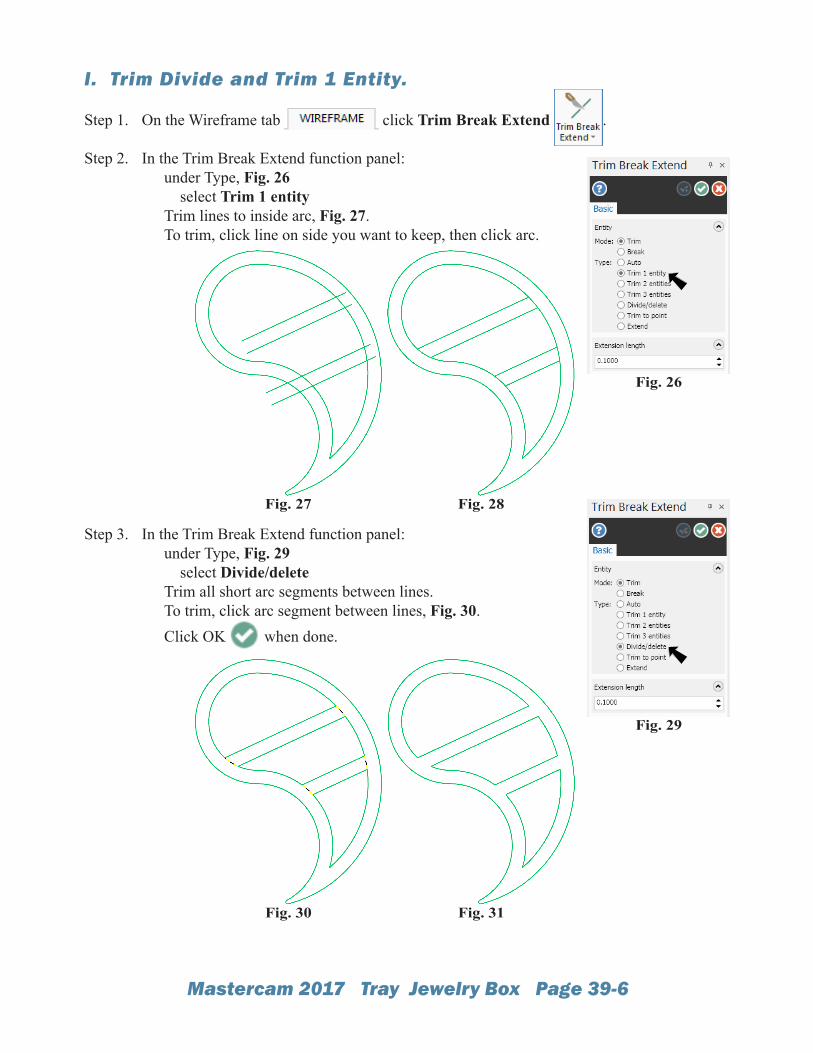
I. Trim Divide and Trim 1 Entity.
Step 1. On the Wireframe tab click Trim Break Extend .
Step 2. In the Trim Break Extend function panel: under Type, Fig. 26 select Trim 1 entity Trim lines to inside arc, Fig. 27. To trim, click line on side you want to keep, then click arc.
Step 3. In the Trim Break Extend function panel: under Type, Fig. 29 select Divide/delete Trim all short arc segments between lines. To trim, click arc segment between lines, Fig. 30. Click OK when done.
Fig. 28Fig. 27
Fig. 29
Fig. 26
Fig. 31Fig. 30
Mastercam 2017 Tray Jewelry Box Page 39-7
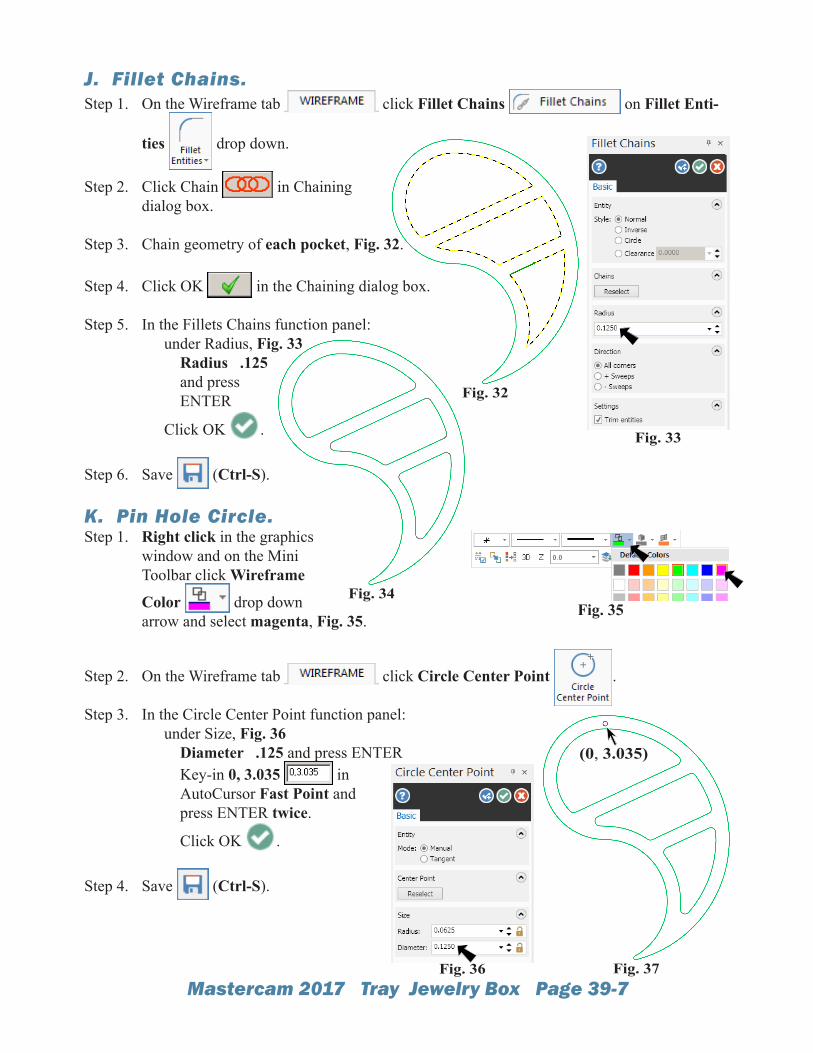
J. Fillet Chains.Step 1. On the Wireframe tab click Fillet Chains on Fillet Enti-
ties drop down.
Step 2. Click Chain in Chainingdialog box.
Step 3. Chain geometry of each pocket, Fig. 32.
Step 4. Click OK in the Chaining dialog box.
Step 5. In the Fillets Chains function panel: under Radius, Fig. 33 Radius .125 and press ENTER
Click OK .
Step 6. Save (Ctrl-S).
K. Pin Hole Circle.Step 1. Right click in the graphics
window and on the Mini Toolbar click Wireframe
Color drop down arrow and select magenta, Fig. 35.
Step 2. On the Wireframe tab click Circle Center Point .
Step 3. In the Circle Center Point function panel: under Size, Fig. 36 Diameter .125 and press ENTER Key-in 0, 3.035 in AutoCursor Fast Point and press ENTER twice.
Click OK .
Step 4. Save (Ctrl-S).
Fig. 33
Fig. 34
Fig. 32
Fig. 35
Fig. 36 Fig. 37
(0, 3.035)
Mastercam 2017 Tray Jewelry Box Page 39-8
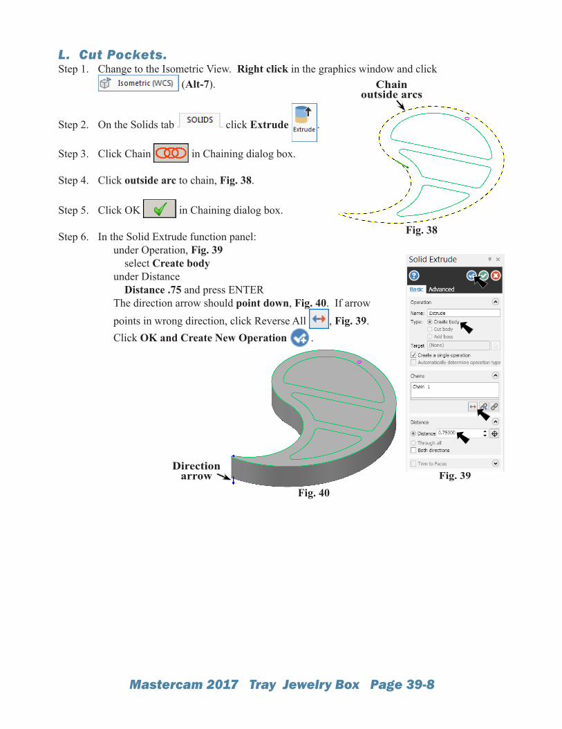
L. Cut Pockets.Step 1. Change to the Isometric View. Right click in the graphics window and click
(Alt-7).
Step 2. On the Solids tab click Extrude .
Step 3. Click Chain in Chaining dialog box.
Step 4. Click outside arc to chain, Fig. 38.
Step 5. Click OK in Chaining dialog box.
Step 6. In the Solid Extrude function panel: under Operation, Fig. 39 select Create body under Distance Distance .75 and press ENTER The direction arrow should point down, Fig. 40. If arrow points in wrong direction, click Reverse All , Fig. 39. Click OK and Create New Operation .
Fig. 38
Fig. 40
Direction arrow Fig. 39
Chain outside arcs
Mastercam 2017 Tray Jewelry Box Page 39-9
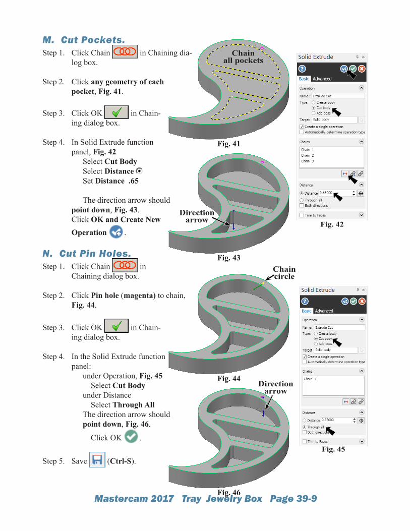
M. Cut Pockets.Step 1. Click Chain in Chaining dia-
log box.
Step 2. Click any geometry of each pocket, Fig. 41.
Step 3. Click OK in Chain-ing dialog box.
Step 4. In Solid Extrude function panel, Fig. 42 Select Cut Body Select Distance Set Distance .65 The direction arrow should point down, Fig. 43.Click OK and Create New Operation .
N. Cut Pin Holes.Step 1. Click Chain in
Chaining dialog box.
Step 2. Click Pin hole (magenta) to chain, Fig. 44.
Step 3. Click OK in Chain-ing dialog box.
Step 4. In the Solid Extrude function panel: under Operation, Fig. 45 Select Cut Body under Distance Select Through All The direction arrow should point down, Fig. 46.
Click OK .
Step 5. Save (Ctrl-S).
Fig. 44
Chain circle
Direction arrow
Fig. 46
Fig. 45
Fig. 41
Chain all pockets
Fig. 43
Direction arrow Fig. 42
Mastercam 2017 Tray Jewelry Box Page 39-10
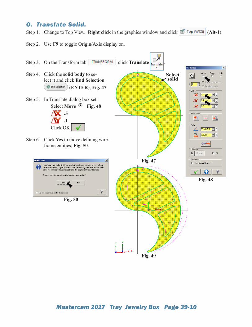
O. Translate Solid.Step 1. Change to Top View. Right click in the graphics window and click (Alt-1).
Step 2. Use F9 to toggle Origin/Axis display on.
Step 3. On the Transform tab click Translate .
Step 4. Click the solid body to se-lect it and click End Selection
(ENTER), Fig. 47.
Step 5. In Translate dialog box set: Select Move Fig. 48 .5 .1 Click OK .
Step 6. Click Yes to move defining wire-frame entities, Fig. 50.
Fig. 48
Fig. 50
Select solid
Fig. 47
Fig. 49
Mastercam 2017 Tray Jewelry Box Page 39-11
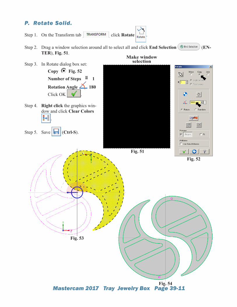
P. Rotate Solid.
Step 1. On the Transform tab click Rotate .
Step 2. Drag a window selection around all to select all and click End Selection (EN-TER), Fig. 51.
Step 3. In Rotate dialog box set: Copy Fig. 52 Number of Steps 1
Rotation Angle 180 Click OK .
Step 4. Right click the graphics win-dow and click Clear Colors
.
Step 5. Save (Ctrl-S).
Fig. 51
Make window selection
Fig. 54
Fig. 52
Fig. 53
Mastercam 2017 Tray Jewelry Box Page 39-12
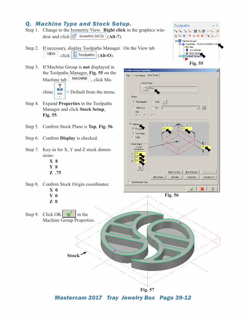
Q. Machine Type and Stock Setup.Step 1. Change to the Isometric View. Right click in the graphics win-
dow and click (Alt-7).
Step 2. If necessary, display Toolpaths Manager. On the View tab click (Alt-O).
Step 3. If Machine Group is not displayed in the Toolpaths Manager, Fig. 55 on the Machine tab , click Ma-
chine > Default from the menu.
Step 4. Expand Properties in the Toolpaths Manager and click Stock Setup,Fig. 55.
Step 5. Confirm Stock Plane is Top, Fig. 56.
Step 6. Confirm Display is checked.
Step 7. Key-in for X, Y and Z stock dimen-sions: X 8 Y 8 Z .75
Step 8. Confirm Stock Origin coordinates: X 0 Y 0 Z 0
Step 9. Click OK in theMachine Group Properties.
Fig. 55
Fig. 56
Stock
Fig. 57
Mastercam 2017 Tray Jewelry Box Page 39-13
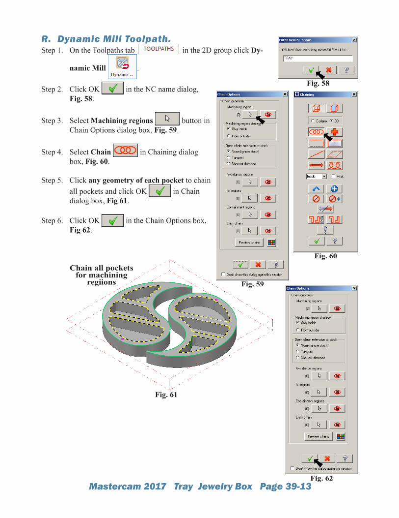
R. Dynamic Mill Toolpath.Step 1. On the Toolpaths tab in the 2D group click Dy-
namic Mill .
Step 2. Click OK in the NC name dialog, Fig. 58.
Step 3. Select Machining regions button in Chain Options dialog box, Fig. 59.
Step 4. Select Chain in Chaining dialog box, Fig. 60.
Step 5. Click any geometry of each pocket to chain all pockets and click OK in Chain dialog box, Fig 61.
Step 6. Click OK in the Chain Options box, Fig 62.
Fig. 61
Fig. 59
Fig. 60
Fig. 62
Fig. 58
Chain all pockets for machining
regiions
Mastercam 2017 Tray Jewelry Box Page 39-14
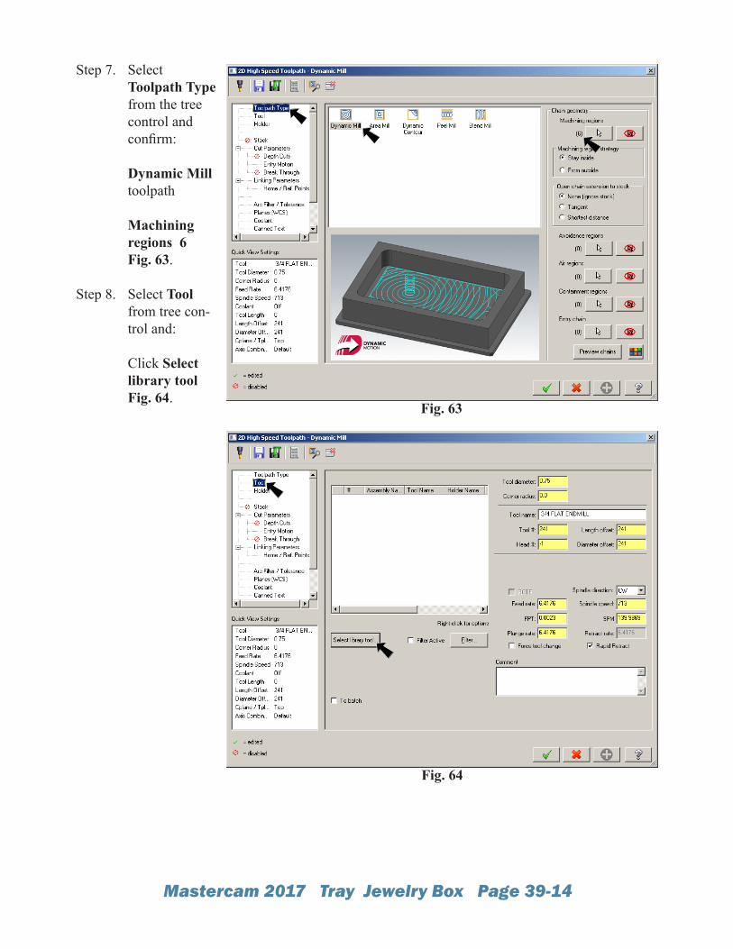
Step 7. Select Toolpath Type from the tree control and confirm: Dynamic Mill toolpath Machining regions 6 Fig. 63.
Step 8. Select Tool from tree con-trol and: Click Select library tool Fig. 64.
Fig. 63
Fig. 64
Mastercam 2017 Tray Jewelry Box Page 39-15
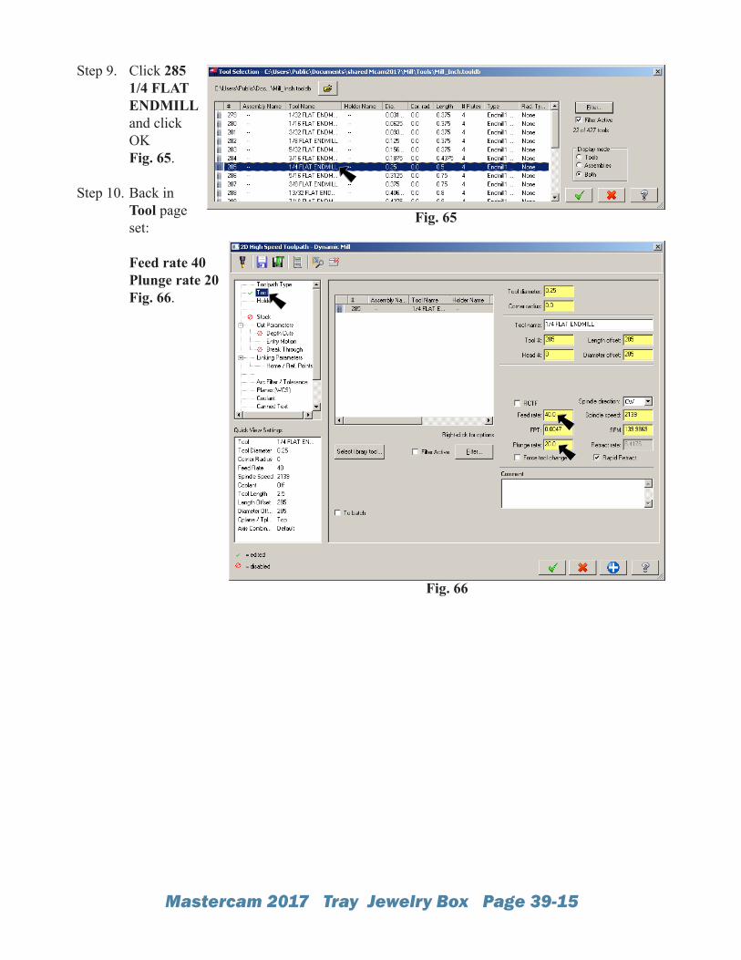
Step 9. Click 285 1/4 FLAT ENDMILL and click OK Fig. 65.
Step 10. Back in Tool page set: Feed rate 40 Plunge rate 20Fig. 66.
Fig. 65
Fig. 66
Mastercam 2017 Tray Jewelry Box Page 39-16
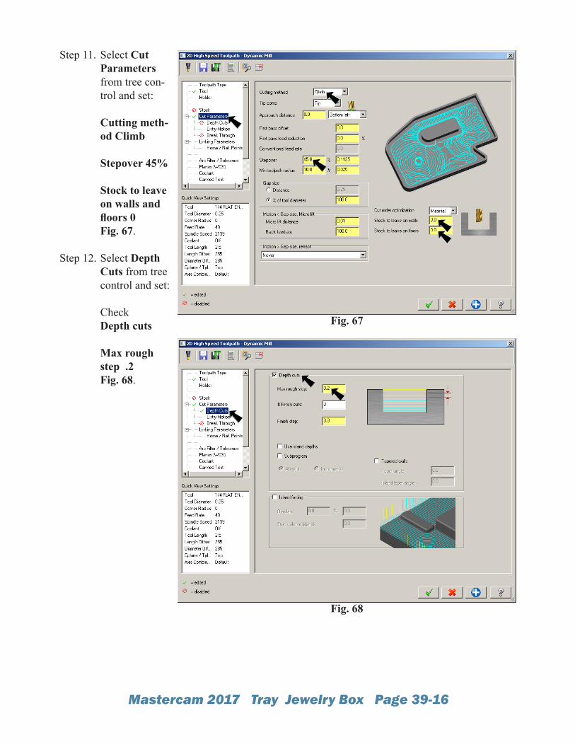
Step 11. Select CutParameters from tree con-trol and set: Cutting meth-od Climb Stepover 45% Stock to leave on walls and floors 0 Fig. 67.
Step 12. Select Depth Cuts from tree control and set: CheckDepth cuts Max rough step .2 Fig. 68.
Fig. 67
Fig. 68
Mastercam 2017 Tray Jewelry Box Page 39-17
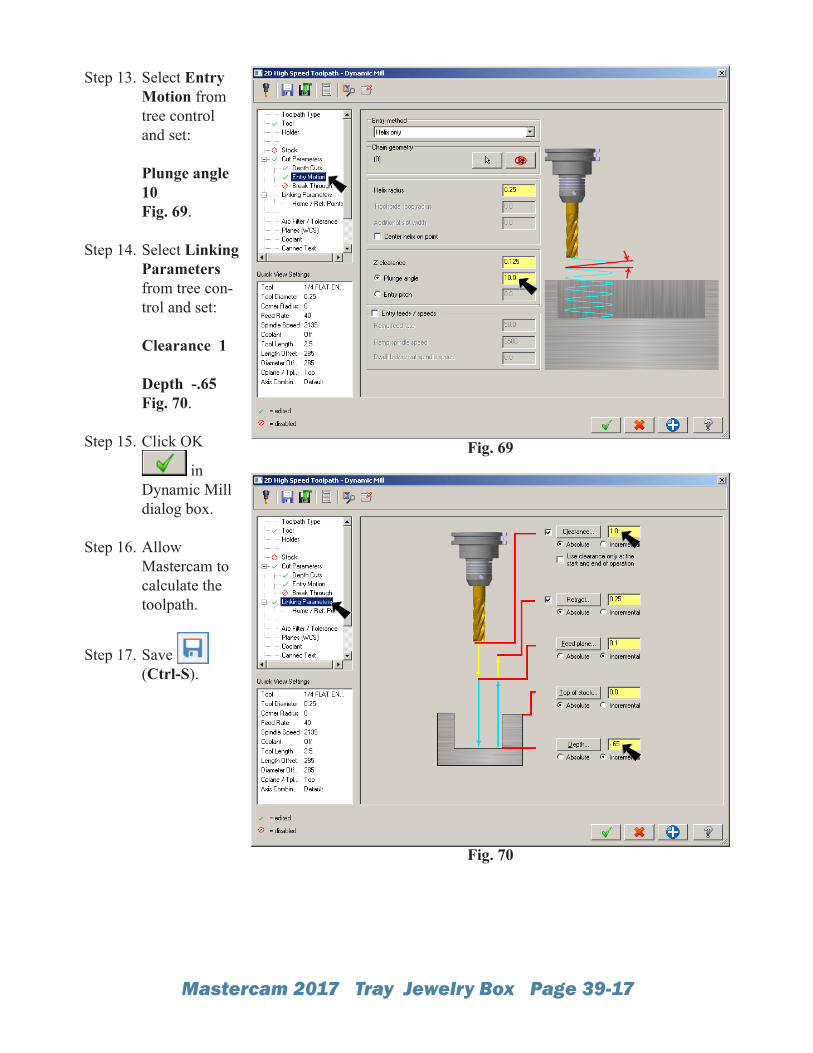
Step 13. Select Entry Motion from tree control and set: Plunge angle 10 Fig. 69.
Step 14. Select Linking Parameters from tree con-trol and set: Clearance 1 Depth -.65 Fig. 70.
Step 15. Click OK
in Dynamic Mill dialog box.
Step 16. Allow Mastercam to calculate the toolpath.
Step 17. Save (Ctrl-S).
Fig. 69
Fig. 70
Mastercam 2017 Tray Jewelry Box Page 39-18
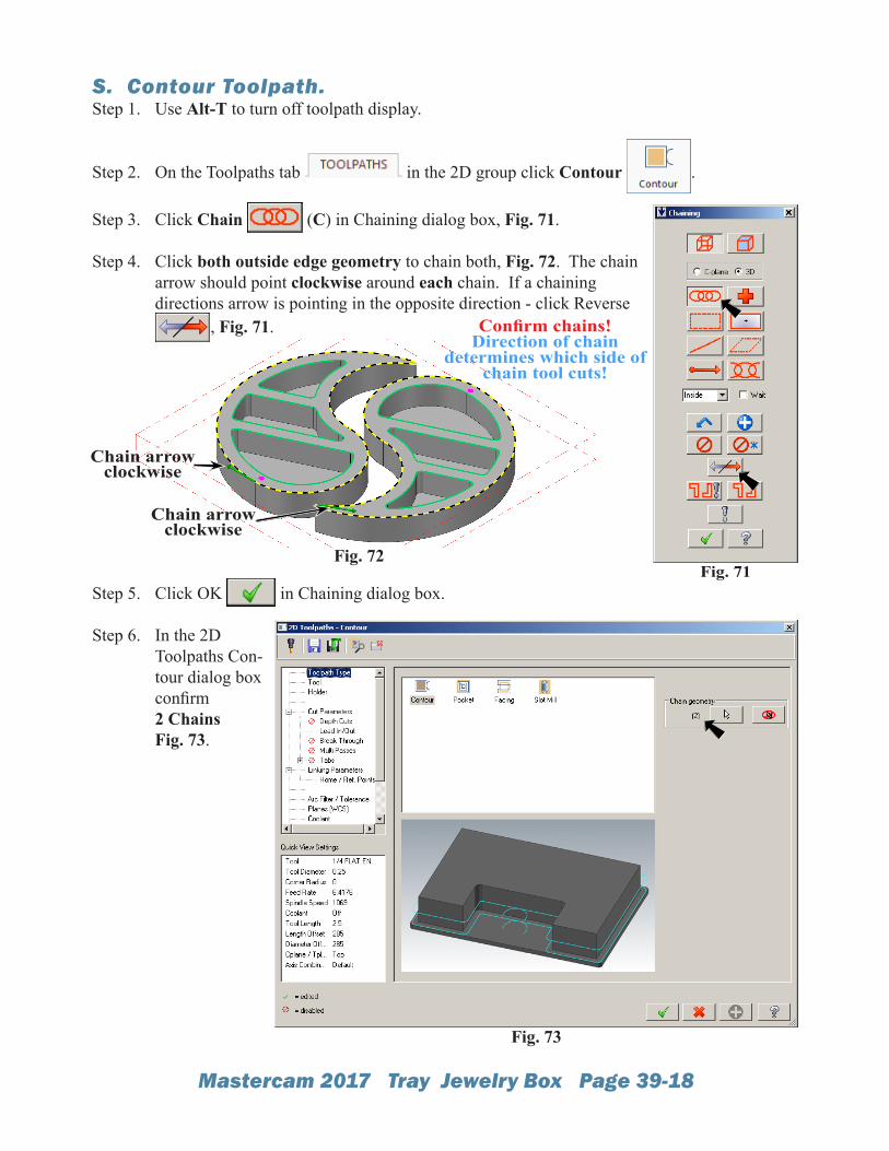
S. Contour Toolpath.Step 1. Use Alt-T to turn off toolpath display.
Step 2. On the Toolpaths tab in the 2D group click Contour .
Step 3. Click Chain (C) in Chaining dialog box, Fig. 71.
Step 4. Click both outside edge geometry to chain both, Fig. 72. The chain arrow should point clockwise around each chain. If a chaining directions arrow is pointing in the opposite direction - click Reverse
, Fig. 71.
Step 5. Click OK in Chaining dialog box.
Step 6. In the 2D Toolpaths Con-tour dialog box confirm 2 ChainsFig. 73.
Fig. 72Fig. 71
Fig. 73
Chain arrow clockwise
Chain arrow clockwise
Confirm chains!Direction of chain
determines which side of chain tool cuts!
Mastercam 2017 Tray Jewelry Box Page 39-19
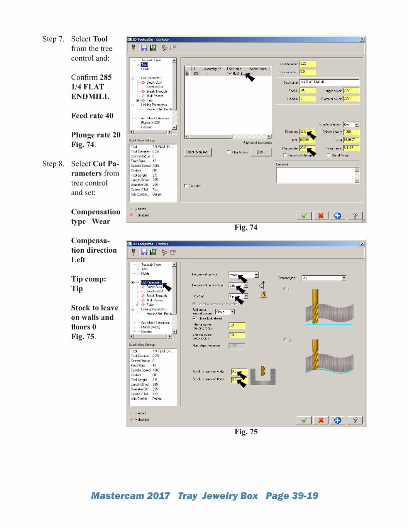
Step 7. Select Tool from the tree control and: Confirm 285 1/4 FLAT ENDMILL Feed rate 40
Plunge rate 20Fig. 74.
Step 8. Select Cut Pa-rameters from tree control and set: Compensation type Wear Compensa-tion direction Left Tip comp: Tip Stock to leave on walls and floors 0 Fig. 75.
Fig. 74
Fig. 75
Mastercam 2017 Tray Jewelry Box Page 39-20
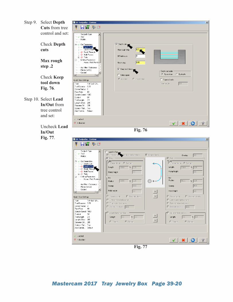
Step 9. Select Depth Cuts from tree control and set: Check Depth cuts
Max rough step .2 Check Keep tool down Fig. 76.
Step 10. Select Lead In/Out from tree control and set: Uncheck Lead In/Out Fig. 77.
Fig. 76
Fig. 77
Mastercam 2017 Tray Jewelry Box Page 39-21
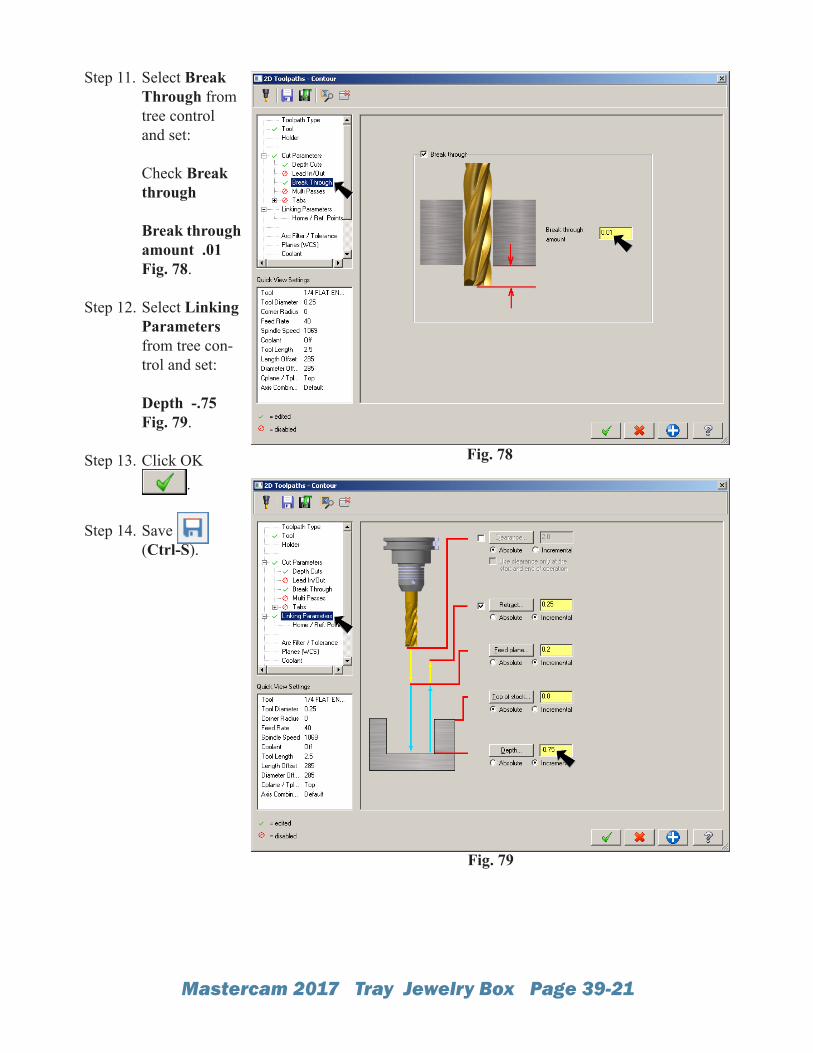
Step 11. Select Break Through from tree control and set: Check Break through Break through amount .01 Fig. 78.
Step 12. Select Linking Parameters from tree con-trol and set: Depth -.75 Fig. 79.
Step 13. Click OK .
Step 14. Save (Ctrl-S).
Fig. 78
Fig. 79
Mastercam 2017 Tray Jewelry Box Page 39-22
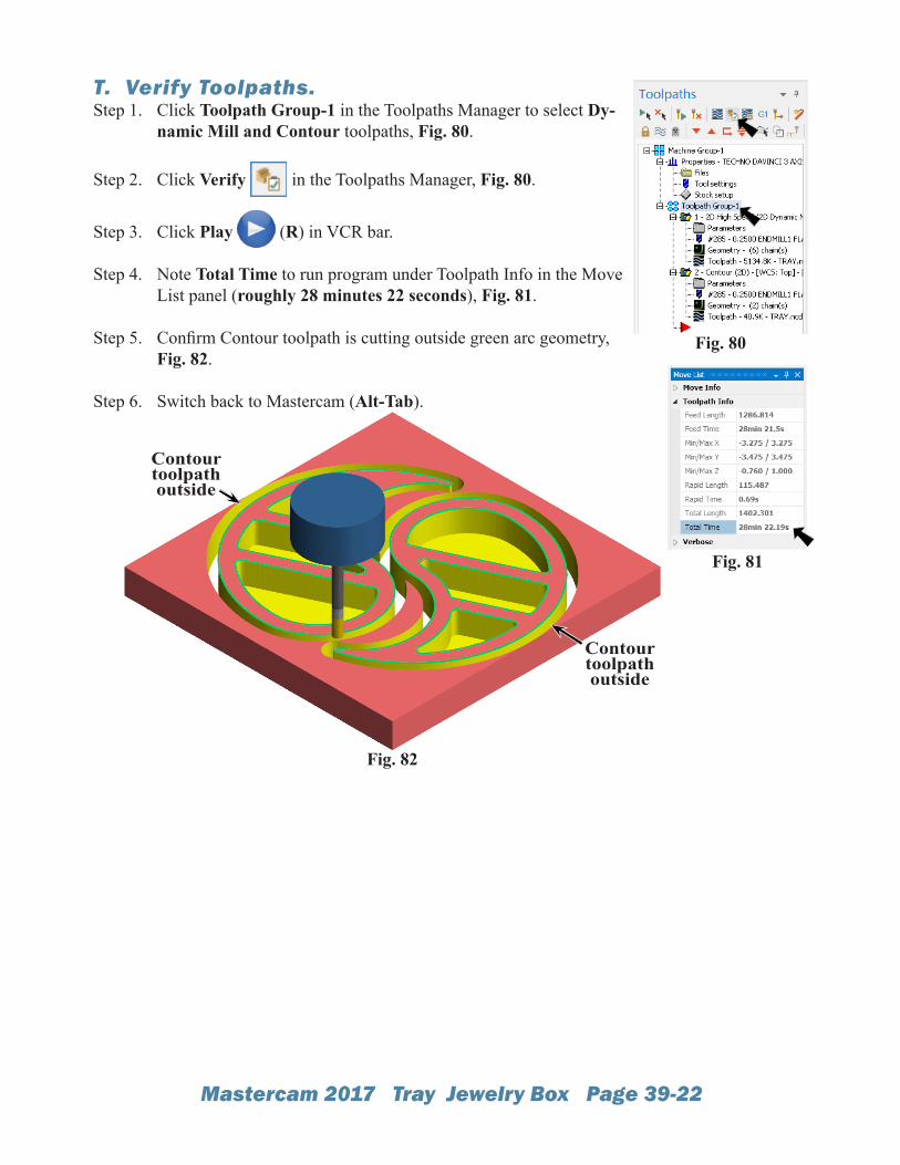
T. Verify Toolpaths.Step 1. Click Toolpath Group-1 in the Toolpaths Manager to select Dy-
namic Mill and Contour toolpaths, Fig. 80.
Step 2. Click Verify in the Toolpaths Manager, Fig. 80.
Step 3. Click Play (R) in VCR bar.
Step 4. Note Total Time to run program under Toolpath Info in the Move List panel (roughly 28 minutes 22 seconds), Fig. 81.
Step 5. Confirm Contour toolpath is cutting outside green arc geometry, Fig. 82.
Step 6. Switch back to Mastercam (Alt-Tab).
Fig. 80
Fig. 82
Fig. 81
Contour toolpath outside
Contour toolpath outside
Mastercam 2017 Tray Jewelry Box Page 39-23
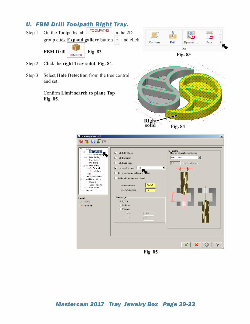
U. FBM Drill Toolpath Right Tray.Step 1. On the Toolpaths tab in the 2D
group click Expand gallery button and click
FBM Drill , Fig. 83.
Step 2. Click the right Tray solid, Fig. 84.
Step 3. Select Hole Detection from the tree control and set: Confirm Limit search to plane TopFig. 85.
Fig. 85
Fig. 84
Fig. 83
Right solid
Mastercam 2017 Tray Jewelry Box Page 39-24
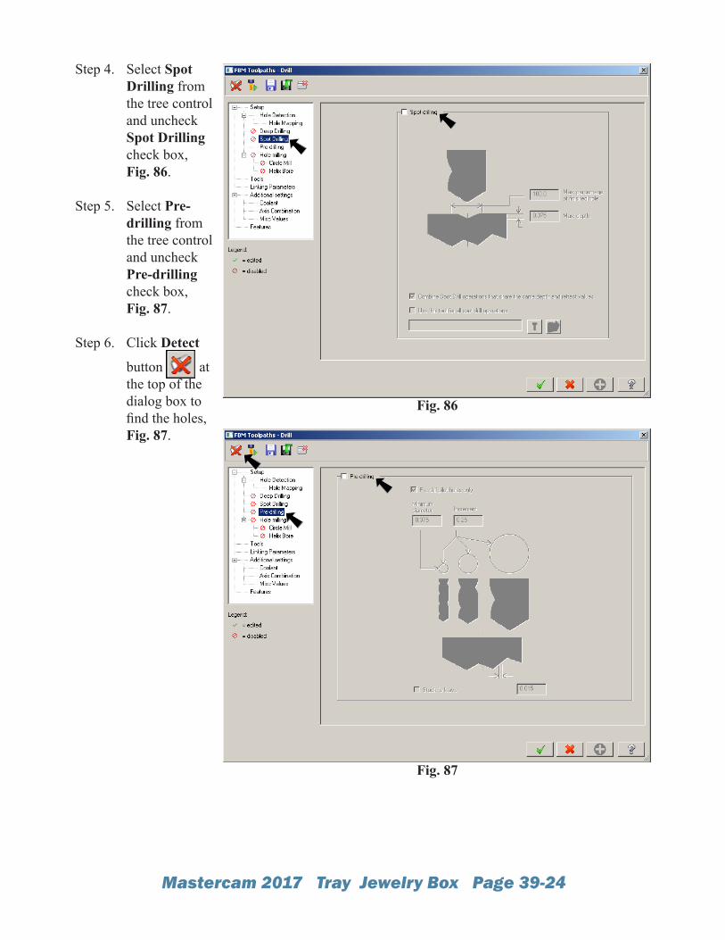
Step 4. Select Spot Drilling from the tree control and uncheck Spot Drilling check box, Fig. 86.
Step 5. Select Pre-drilling from the tree control and uncheck Pre-drilling check box, Fig. 87.
Step 6. Click Detect
button at the top of the dialog box to find the holes, Fig. 87.
Fig. 86
Fig. 87
Mastercam 2017 Tray Jewelry Box Page 39-25
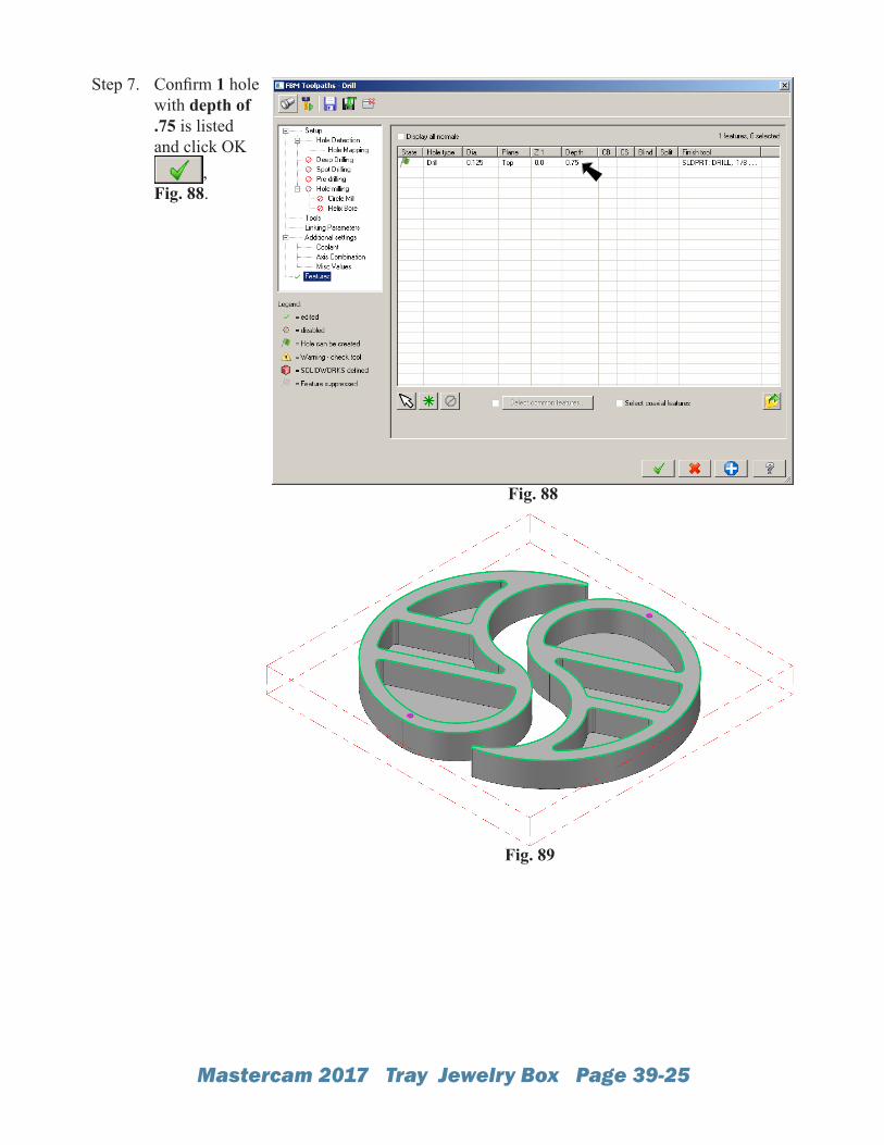
Step 7. Confirm 1 hole with depth of .75 is listed and click OK
,Fig. 88.
Fig. 88
Fig. 89
Mastercam 2017 Tray Jewelry Box Page 39-26
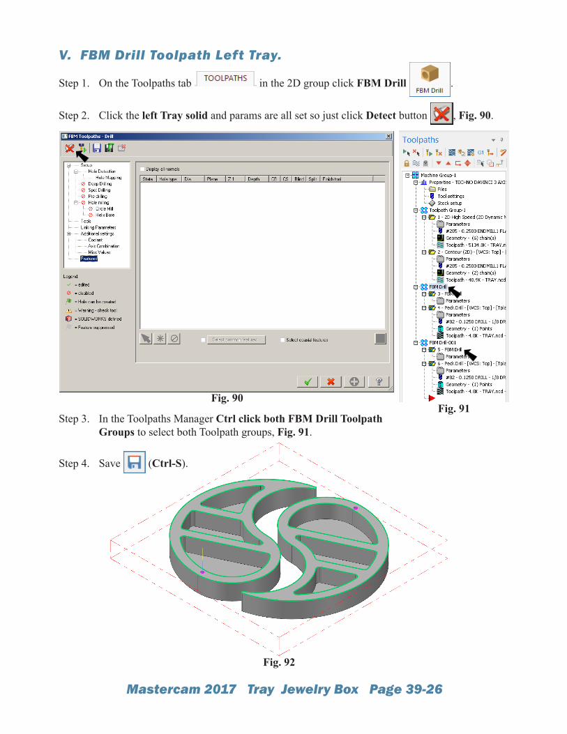
V. FBM Drill Toolpath Left Tray.
Step 1. On the Toolpaths tab in the 2D group click FBM Drill .
Step 2. Click the left Tray solid and params are all set so just click Detect button , Fig. 90.
Step 3. In the Toolpaths Manager Ctrl click both FBM Drill Toolpath Groups to select both Toolpath groups, Fig. 91.
Step 4. Save (Ctrl-S).
Fig. 90
Fig. 92
Fig. 91