Embed Size (px)
Citation preview

Wind AnalysismasterKEY
Wind A
nalysism
aster
KE
Y
2
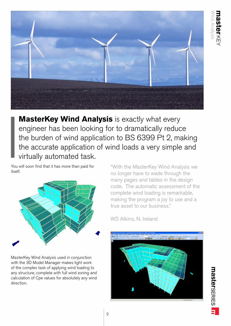
MasterKey Wind Analysis is exactly what every engineer has been looking for to dramatically reduce the burden of wind application to BS 6399 Pt 2, making the accurate application of wind loads a very simple and virtually automated task.
You will soon find that it has more than paid for itself.
MasterKey Wind Analysis used in conjunction with the 3D Model Manager makes light work of the complex task of applying wind loading to any structure, complete with full wind zoning and calculation of Cpe values for absolutely any wind direction.
“With the MasterKey Wind Analysis we no longer have to wade through the many pages and tables in the design code. The automatic assessment of the complete wind loading is remarkable, making the program a joy to use and a true asset to our business.”
WS Atkins, N. Ireland
Wind A
nalysism
aster
KE
Y
3
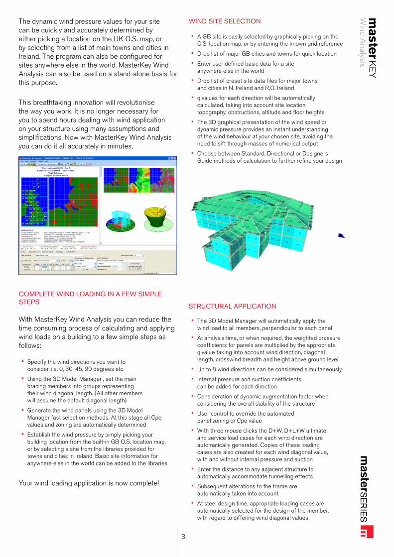
The dynamic wind pressure values for your site can be quickly and accurately determined by either picking a location on the UK O.S. map, or by selecting from a list of main towns and cities in Ireland. The program can also be configured for sites anywhere else in the world. MasterKey Wind Analysis can also be used on a stand-alone basis for this purpose.
This breathtaking innovation will revolutionise the way you work. It is no longer necessary for you to spend hours dealing with wind application on your structure using many assumptions and simplifications. Now with MasterKey Wind Analysis you can do it all accurately in minutes.
COMPLETE WIND LOADING IN A FEW SIMPLE STEPS
With MasterKey Wind Analysis you can reduce the time consuming process of calculating and applying wind loads on a building to a few simple steps as follows:
Specify the wind directions you want to • consider, i.e. 0, 30, 45, 90 degrees etc.
Using the 3D Model Manager , set the main • bracing members into groups representing their wind diagonal length. (All other members will assume the default diagonal length)
Generate the wind panels using the 3D Model • Manager fast selection methods. At this stage all Cpe values and zoning are automatically determined
Establish the wind pressure by simply picking your • building location from the built-in GB O.S. location map, or by selecting a site from the libraries provided for towns and cities in Ireland. Basic site information for anywhere else in the world can be added to the libraries
Your wind loading application is now complete!
WIND SITE SELECTION
A GB site is easily selected by graphically picking on the • O.S. location map, or by entering the known grid reference
Drop list of major GB cities and towns for quick location • Enter user defined basic data for a site • anywhere else in the world
Drop list of preset site data files for major towns • and cities in N. Ireland and R.O. Ireland
q values for each direction will be automatically • calculated, taking into account site location, topography, obstructions, altitude and floor heights
The 3D graphical presentation of the wind speed or • dynamic pressure provides an instant understanding of the wind behaviour at your chosen site, avoiding the need to sift through masses of numerical output
Choose between Standard, Directional or Designers • Guide methods of calculation to further refine your design
STRUCTURAL APPLICATION
The 3D Model Manager will automatically apply the • wind load to all members, perpendicular to each panel
At analysis time, or when required, the weighted pressure • coefficients for panels are multiplied by the appropriate q value taking into account wind direction, diagonal length, crosswind breadth and height above ground level
Up to 8 wind directions can be considered simultaneously • Internal pressure and suction coefficients • can be added for each direction
Consideration of dynamic augmentation factor when • considering the overall stability of the structure
User control to override the automated • panel zoning or Cpe value
With three mouse clicks the D+W, D+L+W ultimate • and service load cases for each wind direction are automatically generated. Copies of these loading cases are also created for each wind diagonal value, with and without internal pressure and suction
Enter the distance to any adjacent structure to • automatically accommodate funnelling effects
Subsequent alterations to the frame are • automatically taken into account
At steel design time, appropriate loading cases are • automatically selected for the design of the member, with regard to differing wind diagonal values
Wind A
nalysism
aster
KE
Y
4
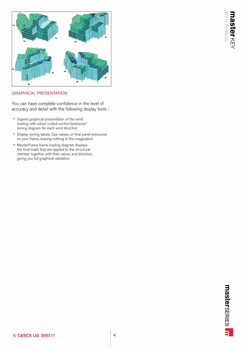
GRAPHICAL PRESENTATION
You can have complete confidence in the level of accuracy and detail with the following display tools :
Superb graphical presentation of the wind • loading with colour coded suction/pressure/zoning diagram for each wind direction
Display zoning labels, Cpe values, or final panel pressures • on your frame, leaving nothing to the imagination
MasterFrame frame loading diagram displays • the final loads that are applied to the structural member together with their values and direction, giving you full graphical validation
© C&SCS Ltd. 2007.11

EmailTechnical Support: [email protected]: [email protected]
Webwww.masterseries.co.uk
MasterSeriesCivil & Structural Computer Services Limited1 Circular RoadNewtownabbeyCo. AntrimBT37 0RAUnited Kingdom
PhoneUK: 028 9036 5950 RoI: 048 9036 5950Overseas: +44 28 9036 5950
Fax UK: 028 9036 5102RoI: 048 9036 5102Overseas: +44 28 9036 5102
More information